JP2005293418A - Information processor, network system, throughput presentation method and program for throughput presentation - Google Patents
Information processor, network system, throughput presentation method and program for throughput presentation Download PDFInfo
- Publication number
- JP2005293418A JP2005293418A JP2004110256A JP2004110256A JP2005293418A JP 2005293418 A JP2005293418 A JP 2005293418A JP 2004110256 A JP2004110256 A JP 2004110256A JP 2004110256 A JP2004110256 A JP 2004110256A JP 2005293418 A JP2005293418 A JP 2005293418A
- Authority
- JP
- Japan
- Prior art keywords
- information processing
- processing apparatus
- information
- processor
- program
- Prior art date
- Legal status (The legal status is an assumption and is not a legal conclusion. Google has not performed a legal analysis and makes no representation as to the accuracy of the status listed.)
- Pending
Links
Images


Landscapes
- User Interface Of Digital Computer (AREA)
Abstract
Description
この発明は、ネットワーク上に接続される情報処理装置、複数の情報処理装置が同一ネットワーク上に接続されたネットワークシステム、そのネットワークシステムにおいて各情報処理装置の処理能力を呈示する方法、および各情報処理装置の処理能力を呈示するためのコンピュータプログラムに関する。 The present invention relates to an information processing apparatus connected to a network, a network system in which a plurality of information processing apparatuses are connected to the same network, a method of presenting the processing capability of each information processing apparatus in the network system, and each information processing The present invention relates to a computer program for presenting the processing capability of an apparatus.
最近、グリッド・コンピューティングが注目されている。グリッド・コンピューティングとは、ネットワーク上に接続された複数の情報処理装置を協調動作させて、高い演算性能を実現する技術である。 Recently, grid computing has attracted attention. Grid computing is a technology that realizes high computing performance by cooperating a plurality of information processing devices connected on a network.
例えば、特許文献1(特開2002−342165号公報)、特許文献2(特開2002−351850号公報)、特許文献3(特開2002−358289号公報)、特許文献4(特開2002−366533号公報)および特許文献5(特開2002−366534号公報)には、均一なモジュラー構造、共通のコンピューティング・モジュール、および均一なソフトウェアセルを用いることによって、高速処理用コンピュータ・アーキテクチャを実現することが示されている。 For example, Patent Document 1 (JP 2002-342165 A), Patent Document 2 (JP 2002-351850 A), Patent Document 3 (JP 2002-358289 A), Patent Document 4 (JP 2002-366533 A). And Patent Document 5 (Japanese Patent Laid-Open No. 2002-366534) realize a high-speed computer architecture by using a uniform modular structure, a common computing module, and a uniform software cell. It has been shown.
上に挙げた先行技術文献は、以下の通りである。
しかし、複数の情報処理装置が同一ネットワーク上に接続されたネットワークシステムで、ある処理を各情報処理装置に分散的に実行させるなど、各情報処理装置を連携させて動作させる場合、各情報処理装置の処理能力は同じではなく、例えば、ある情報処理装置は、もともとプロセッサ(CPU)の処理能力が高いものの、現にプロセッサがプログラムを実行しているために、当該情報処理装置のそのときの処理能力が低い場合や、ある情報処理装置は、メインメモリの総容量が大きいものの、現にメインメモリの多くの容量を使用しているために、メインメモリの空き容量が小さく、当該情報処理装置のそのときの処理能力が低い場合などがある。 However, in a network system in which a plurality of information processing devices are connected to the same network, when each information processing device is operated in cooperation, such as causing a certain process to be executed in a distributed manner, each information processing device For example, a certain information processing apparatus originally has a high processing capacity of a processor (CPU), but since the processor is actually executing a program, the processing capacity of the information processing apparatus at that time Is low or a certain information processing device uses a large amount of main memory, although the total capacity of the main memory is large, the free space of the main memory is small. There are cases where the processing capacity of the system is low.
さらに、レイテンシー(latency)、すなわち通信レートに逆比例する待ち時間も、各情報処理装置で同じではなく、その時々の状況に応じても変わり得る。 Furthermore, the latency, that is, the waiting time inversely proportional to the communication rate, is not the same in each information processing apparatus, and may vary depending on the situation at that time.
そのため、一定の処理の実行に要する時間、いわゆるターンアラウンドタイム(turn around time)は、各情報処理装置で同じではなく、その時々の状況に応じても変わり得る。 For this reason, the time required for execution of a certain process, the so-called turn around time, is not the same in each information processing apparatus, and may vary depending on the situation at that time.
しかしながら、ユーザは、ネットワークシステムの外観から、そのときの各情報処理装置の以上のような処理能力を知ることができない。そのため、ユーザは、例えば、そのときの処理能力が最大の情報処理装置に処理を実行させようと思っても、そうすることができない。 However, the user cannot know the processing capability of each information processing apparatus at that time from the appearance of the network system. Therefore, for example, even if the user intends to cause the information processing apparatus having the maximum processing capability to execute the process, the user cannot do so.
そこで、この発明は、複数の情報処理装置が同一ネットワーク上に接続されたネットワークシステムにおいて、ユーザが、その時々の各情報処理装置の処理能力を直感的かつ的確に把握することができ、ユーザ自身の選択によって適切な情報処理装置に処理を実行させることも可能となるようにしたものである。 Therefore, the present invention is a network system in which a plurality of information processing devices are connected to the same network, so that the user can intuitively and accurately grasp the processing capability of each information processing device at that time. This makes it possible to cause an appropriate information processing apparatus to execute processing.
この発明の情報処理装置は、
ネットワーク上に接続される情報処理装置であって、
プログラムを実行するプロセッサ手段と、
プログラムおよびデータが展開されるメモリ手段と、
当該情報処理装置、および前記ネットワークを介して当該情報処理装置と接続された、プロセッサ手段およびメモリ手段を備える他の情報処理装置の、そのときの処理能力を示す情報を収集し、そのときの処理能力をチャートとしてディスプレイ上に表示する管理手段と、
を備えることを特徴とする。
The information processing apparatus of the present invention
An information processing apparatus connected to a network,
Processor means for executing a program;
Memory means in which programs and data are expanded;
Collects information indicating the current processing capability of the information processing apparatus and another information processing apparatus including the processor means and the memory means connected to the information processing apparatus via the network, and processes at that time A management means for displaying the ability as a chart on the display;
It is characterized by providing.
上記の構成の、この発明の情報処理装置が複数、同一ネットワーク上に接続されたネットワークシステムでは、ユーザが、ある情報処理装置に処理能力の呈示を指示することによって、当該情報処理装置の管理手段は、自装置および他装置(他の情報処理装置)の、そのときの処理能力を示す情報を収集し、そのときの処理能力をチャートとしてディスプレイ上に表示する。 In a network system in which a plurality of information processing apparatuses of the present invention having the above-described configuration are connected to the same network, the user instructs a certain information processing apparatus to present a processing capability, whereby the management means of the information processing apparatus Collects information indicating the processing capability at that time of its own device and other devices (other information processing devices) and displays the processing capability at that time as a chart on the display.
したがって、ユーザは、そのチャートを見て、各情報処理装置のプロセッサ手段の余剰能力、各情報処理装置のメモリ手段の空き容量、各情報処理装置に接続された外部記録手段の空き容量、各情報処理装置の通信レートなど、各情報処理装置のそのときの処理能力を、直感的かつ的確に把握することができ、各情報処理装置に処理を実行させたときのターンアラウンドタイムを予測することができる。したがって、ユーザ自身の選択によって、適切な情報処理装置に処理を実行させることも可能となる。 Therefore, the user looks at the chart, the surplus capacity of the processor means of each information processing apparatus, the free capacity of the memory means of each information processing apparatus, the free capacity of the external recording means connected to each information processing apparatus, and each information The processing capability of each information processing device at that time, such as the communication rate of the processing device, can be grasped intuitively and accurately, and the turnaround time when each information processing device executes processing can be predicted. it can. Therefore, it is possible to cause an appropriate information processing apparatus to execute processing by the user's own selection.
以上のように、この発明によれば、ユーザは、その時々の各情報処理装置の処理能力を直感的かつ的確に把握することができ、ユーザ自身の選択によって適切な情報処理装置に処理を実行させることも可能となる。 As described above, according to the present invention, the user can intuitively and accurately grasp the processing capability of each information processing apparatus at each time, and executes processing to an appropriate information processing apparatus by the user's own selection. It is also possible to make it.
〔1.ネットワークシステムおよび情報処理装置の基本的構成:図1〜図4〕
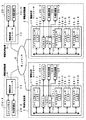
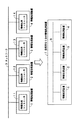
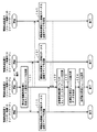
図1は、この発明のネットワークシステムの一例を示し、ネットワーク9を介して複数の情報処理装置1,2,3および4が接続されたものである。
[1. Basic configuration of network system and information processing apparatus: FIGS. 1 to 4]
FIG. 1 shows an example of a network system according to the present invention, in which a plurality of
(1−1.情報処理装置および情報処理コントローラ:図1)
情報処理装置1,2,3および4は、それぞれ、後述のような各種のAV(Audio and Visual)機器やポータブル機器である。
(1-1. Information processing apparatus and information processing controller: FIG. 1)
The
情報処理装置1について示すと、情報処理装置1は、コンピュータ機能部として情報処理コントローラ11を備える。情報処理コントローラ11は、メインプロセッサ21−1、サブプロセッサ23−1,23−2および23−3、DMAC(ダイレクトメモリアクセスコントローラ)25−1、およびDC(ディスクコントローラ)27−1を有する。
As for the
メインプロセッサ21−1は、サブプロセッサ23−1,23−2および23−3によるプログラム実行(データ処理)のスケジュール管理と、情報処理コントローラ11(情報処理装置1)の全般的な管理とを行う。ただし、メインプロセッサ21−1内で管理のためのプログラム以外のプログラムが動作するように構成することもできる。メインプロセッサ21−1は、LS(ローカルストレージ)22−1を有する。 The main processor 21-1 performs schedule management of program execution (data processing) by the sub processors 23-1, 23-2, and 23-3, and general management of the information processing controller 11 (information processing apparatus 1). . However, a program other than the management program may be operated in the main processor 21-1. The main processor 21-1 has an LS (local storage) 22-1.
サブプロセッサは、一つでもよいが、望ましくは複数とする。この例は、複数の場合である。 The number of sub processors may be one, but preferably a plurality of sub processors. This example is a plurality of cases.
各サブプロセッサ23−1,23−2および23−3は、メインプロセッサ21−1の制御によって並列的かつ独立に、プログラムを実行し、データを処理する。さらに、場合によってメインプロセッサ21−1内のプログラムがサブプロセッサ23−1,23−2または23−3内のプログラムと連携して動作するように構成することもできる。各サブプロセッサ23−1,23−2および23−3も、LS(ローカルストレージ)24−1,24−2および24−3を有する。 Each of the sub processors 23-1, 23-2 and 23-3 executes a program and processes data in parallel and independently under the control of the main processor 21-1. Further, in some cases, the program in the main processor 21-1 can be configured to operate in cooperation with the program in the sub-processor 23-1, 23-2 or 23-3. Each of the sub processors 23-1, 23-2, and 23-3 also has LS (local storage) 24-1, 24-2, and 24-3.
DMAC25−1は、情報処理コントローラ11に接続されたDRAM(ダイナミックRAM)などからなるメインメモリ26−1に格納されているプログラムおよびデータにアクセスするものであり、DC27−1は、情報処理コントローラ11に接続された外部記録部28−1および28−2にアクセスするものである。
The DMAC 25-1 accesses a program and data stored in a main memory 26-1 including a DRAM (dynamic RAM) connected to the
外部記録部28−1および28−2は、固定ディスク(ハードディスク)でも、リムーバブルディスクでもよく、また、MO,CD±RW,DVD±RWなどの光ディスク、メモリディスク、SRAM(スタティックRAM)、ROMなど、各種のものを用いることができる。したがって、DC27−1は、ディスクコントローラと称するが、外部記録部コントローラである。 The external recording units 28-1 and 28-2 may be fixed disks (hard disks) or removable disks, and optical disks such as MO, CD ± RW, DVD ± RW, memory disks, SRAM (static RAM), ROM, etc. Various types can be used. Therefore, although DC27-1 is called a disk controller, it is an external recording unit controller.
図1の例のように、情報処理コントローラ11に対して外部記録部28を複数接続できるように、情報処理コントローラ11を構成することができる。
As in the example of FIG. 1, the
メインプロセッサ21−1、各サブプロセッサ23−1,23−2および23−3、DMAC25−1、およびDC27−1は、バス29−1によって接続される。 The main processor 21-1, the sub processors 23-1, 23-2 and 23-3, the DMAC 25-1, and the DC 27-1 are connected by a bus 29-1.
情報処理コントローラ11には、当該の情報処理コントローラ11を備える情報処理装置1をネットワーク全体を通して一意的に識別できる識別子が、情報処理装置IDとして割り当てられる。
An identifier that can uniquely identify the
メインプロセッサ21−1、および各サブプロセッサ23−1,23−2および23−3に対しても同様に、それぞれを特定できる識別子が、メインプロセッサIDおよびサブプロセッサIDとして割り当てられる。 Similarly, identifiers that can identify the main processor 21-1 and the sub processors 23-1, 23-2, and 23-3 are assigned as the main processor ID and the sub processor ID.
情報処理コントローラ11は、ワンチップIC(集積回路)として構成することが望ましい。
The
他の情報処理装置2、3および4も、同様に構成される。ここで、親番号が同一であるユニットは枝番号が異なっていても、特に断りがない限り、同じ働きをするものとする。また、以下の説明で枝番号が省略されている場合には、枝番号の違いにいる差異を生じないものとする。
The other
(1−2.各サブプロセッサからメインメモリへのアクセス:図2)
上述したように、一つの情報処理コントローラ内の各サブプロセッサ23は、独立にプログラムを実行し、データを処理するが、異なるサブプロセッサがメインメモリ26内の同一領域に対して同時に読み出しまたは書き込みを行った場合には、データの不整合を生じ得る。そこで、サブプロセッサ23からメインメモリ26へのアクセスは、以下のように行う。
(1-2. Access to main memory from each sub-processor: Fig. 2)
As described above, each
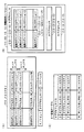
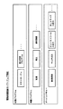
図2(A)に示すように、メインメモリ26は、複数のアドレスを指定できるメモリロケーションによって構成される。各メモリロケーションに対しては、データの状態を示す情報を格納するための追加セグメントが割り振られる。追加セグメントは、F/Eビット、サブプロセッサIDおよびLSアドレス(ローカルストレージアドレス)を含むものとされる。また、各メモリロケーションには、後述のアクセスキーも割り振られる。F/Eビットは、以下のように定義される。 As shown in FIG. 2A, the main memory 26 is composed of memory locations that can specify a plurality of addresses. Each memory location is allocated an additional segment for storing information indicating the state of the data. The additional segment includes an F / E bit, a sub processor ID, and an LS address (local storage address). Each memory location is also assigned an access key to be described later. The F / E bit is defined as follows.
F/Eビット=0は、サブプロセッサ23によって読み出されている処理中のデータ、または空き状態であるため最新データではない無効データであり、読み出し不可であることを示す。また、F/Eビット=0は、当該メモリロケーションにデータ書き込み可能であることを示し、書き込み後に1に設定される。 The F / E bit = 0 indicates that the data being processed being read by the sub-processor 23 or invalid data that is not the latest data because it is empty and cannot be read. The F / E bit = 0 indicates that data can be written to the memory location, and is set to 1 after writing.
F/Eビット=1は、当該メモリロケーションのデータがサブプロセッサ23によって読み出されておらず、未処理の最新データであることを示す。当該メモリロケーションのデータは読み出し可能であり、サブプロセッサ23によって読み出された後に0に設定される。また、F/Eビット=1は、当該メモリロケーションがデータ書き込み不可であることを示す。 The F / E bit = 1 indicates that the data at the memory location has not been read by the sub-processor 23 and is the latest unprocessed data. The data in the memory location can be read and set to 0 after being read by the sub-processor 23. Further, the F / E bit = 1 indicates that the memory location cannot write data.
さらに、F/Eビット=0(読み出し不可/書き込み可)の状態において、当該メモリロケーションについて読み出し予約を設定することは可能である。F/Eビット=0のメモリロケーションに対して読み出し予約を行う場合には、サブプロセッサ23は、読み出し予約を行うメモリロケーションの追加セグメントに、読み出し予約情報として当該サブプロセッサ23のサブプロセッサIDおよびLSアドレスを書き込む。
Furthermore, it is possible to set a read reservation for the memory location in a state where the F / E bit = 0 (read disabled / write enabled). When a read reservation is made for a memory location with the F / E bit = 0, the
その後、データ書き込み側のサブプロセッサ23によって、読み出し予約されたメモリロケーションにデータが書き込まれ、F/Eビット=1(読み出し可/書き込み不可)に設定されたとき、あらかじめ読み出し予約情報として追加セグメントに書き込まれたサブプロセッサIDおよびLSアドレスに読み出される。 Thereafter, when data is written to the memory location reserved for reading by the sub-processor 23 on the data writing side and the F / E bit is set to 1 (readable / not writable), it is added to the additional segment as read reservation information in advance. Read to the written sub-processor ID and LS address.
複数のサブプロセッサによってデータを多段階に処理する必要がある場合、このように各メモリロケーションのデータの読み出し/書き込みを制御することによって、前段階の処理を行うサブプロセッサ23が、処理済みのデータをメインメモリ26上の所定のアドレスに書き込んだ後に即座に、後段階の処理を行う別のサブプロセッサ23が前処理後のデータを読み出すことが可能となる。 When it is necessary to process data in multiple stages by a plurality of sub-processors, the sub-processor 23 that performs the process in the previous stage controls the read / write of the data in each memory location in this way. Immediately after the data is written at a predetermined address on the main memory 26, another sub-processor 23 that performs the subsequent processing can read the data after the preprocessing.
図2(B)に示すように、各サブプロセッサ23内のLS24も、複数のアドレスを指定できるメモリロケーションによって構成される。各メモリロケーションに対しては、同様に追加セグメントが割り振られる。追加セグメントは、ビジービットを含むものとされる。
As shown in FIG. 2B, the
サブプロセッサ23がメインメモリ26内のデータを自身のLS24のメモリロケーションに読み出すときには、対応するビジービットを1に設定して予約する。ビジービットが1であるメモリロケーションには、他のデータは格納することができない。LS24のメモリロケーションに読み出し後、ビジービットは0になり、任意の目的に使用できるようになる。
When the sub-processor 23 reads the data in the main memory 26 to the memory location of its
図2(A)に示すように、さらに、各情報処理コントローラに接続されたメインメモリ26には、複数のサンドボックスが含まれる。サンドボックスは、メインメモリ26内の領域を画定するものであり、各サンドボックスは、各サブプロセッサ23に割り当てられ、そのサブプロセッサが排他的に使用することができる。すなわち、各々のサブプロセッサ23は、自身に割り当てられたサンドボックスを使用できるが、この領域を超えてデータのアクセスを行うことはできない。
As shown in FIG. 2A, the main memory 26 connected to each information processing controller further includes a plurality of sandboxes. The sandbox defines an area in the main memory 26, and each sandbox is assigned to each
メインメモリ26は複数のメモリロケーションから構成されるが、サンドボックスは、これらのメモリロケーションの集合である。 The main memory 26 is composed of a plurality of memory locations, and the sandbox is a collection of these memory locations.
さらに、メインメモリ26の排他的な制御を実現するために、図2(C)に示すようなキー管理テーブルが用いられる。キー管理テーブルは、情報処理コントローラ内のSRAMのような比較的高速のメモリに格納され、DMAC25と関連付けられる。キー管理テーブル内の各エントリには、サブプロセッサID、サブプロセッサキーおよびキーマスクが含まれる。 Further, in order to realize exclusive control of the main memory 26, a key management table as shown in FIG. The key management table is stored in a relatively high-speed memory such as SRAM in the information processing controller, and is associated with the DMAC 25. Each entry in the key management table includes a sub processor ID, a sub processor key, and a key mask.
サブプロセッサ23がメインメモリ26を使用する際のプロセスは、以下のとおりである。まず、サブプロセッサ23はDMAC25に、読み出しまたは書き込みのコマンドを出力する。このコマンドには、自身のサブプロセッサIDと、使用要求先であるメインメモリ26のアドレスが含まれる。
The process when the
DMAC25は、このコマンドを実行する前に、キー管理テーブルを参照して、使用要求元のサブプロセッサのサブプロセッサキーを調べる。次に、DMAC25は、調べた使用要求元のサブプロセッサキーと、使用要求先であるメインメモリ26内の図2(A)に示したメモリロケーションに割り振られたアクセスキーとを比較して、2つのキーが一致した場合にのみ、上記のコマンドを実行する。 Before executing this command, the DMAC 25 refers to the key management table and checks the sub processor key of the sub processor of the use request source. Next, the DMAC 25 compares the checked sub-processor key of the use request source with the access key allocated to the memory location shown in FIG. Execute the above command only when two keys match.
図2(C)に示したキー管理テーブル上のキーマスクは、その任意のビットが1になることによって、そのキーマスクに関連付けられたサブプロセッサキーの対応するビットが0または1になることができる。 In the key mask on the key management table shown in FIG. 2C, when the arbitrary bit becomes 1, the corresponding bit of the sub-processor key associated with the key mask may become 0 or 1. it can.
例えば、サブプロセッサキーが1010であるとする。通常、このサブプロセッサキーによって1010のアクセスキーを持つサンドボックスへのアクセスだけが可能になる。しかし、このサブプロセッサキーと関連付けられたキーマスクが0001に設定されている場合には、キーマスクのビットが1に設定された桁のみにつき、サブプロセッサキーとアクセスキーとの一致判定がマスクされ、このサブプロセッサキー1010によって、アクセスキーが1010または1011のいずれかであるアクセスキーを持つサンドボックスへのアクセスが可能となる。 For example, assume that the sub-processor key is 1010. Normally, this sub-processor key only allows access to a sandbox with 1010 access keys. However, if the key mask associated with this sub-processor key is set to 0001, the match determination between the sub-processor key and the access key is masked only for the digit whose key mask bit is set to 1. The sub processor key 1010 enables access to a sandbox having an access key whose access key is either 1010 or 1011.
以上のようにして、メインメモリ26のサンドボックスの排他性が実現される。すなわち、一つの情報処理コントローラ内の複数のサブプロセッサによってデータを多段階に処理する必要がある場合、以上のように構成することによって、前段階の処理を行うサブプロセッサと、後段階の処理を行うサブプロセッサのみが、メインメモリ26の所定アドレスにアクセスできるようになり、データを保護することができる。 As described above, the sandbox exclusivity of the main memory 26 is realized. In other words, when it is necessary to process data in multiple stages by a plurality of sub-processors in one information processing controller, by configuring as described above, a sub-processor that performs the process in the previous stage and a process in the subsequent stage Only the sub processor that performs the access can access a predetermined address in the main memory 26, and data can be protected.
具体的に、以下のように使用する。まず、情報処理装置の起動直後においては、キーマスクの値は全てゼロである。メインプロセッサ内のプログラムが実行され、サブプロセッサ内のプログラムと連携動作するものとする。第1のサブプロセッサにより出力された処理結果データを一旦メインメモリに格納し、第2のサブプロセッサに入力したいときには、該当するメインメモリ領域は、当然どちらのサブプロセッサからもアクセス可能である必要がある。そのような場合に、メインプロセッサ内のプログラムは、キーマスクの値を適切に変更し、複数のサブプロセッサからアクセスできるメインメモリ領域を設けることにより、サブプロセッサによる多段階的な処理を可能にする。 Specifically, it is used as follows. First, immediately after the information processing apparatus is activated, the values of the key masks are all zero. It is assumed that a program in the main processor is executed and operates in cooperation with a program in the sub processor. When the processing result data output by the first sub-processor is temporarily stored in the main memory and desired to be input to the second sub-processor, the corresponding main memory area must naturally be accessible from either sub-processor. is there. In such a case, the program in the main processor appropriately changes the value of the key mask and provides a main memory area that can be accessed from a plurality of sub processors, thereby enabling multi-stage processing by the sub processors. .
より具体的には、他の情報処理装置からのデータ→第1のサブプロセッサによる処理→第1のメインメモリ領域→第2のサブプロセッサによる処理→第2のメインメモリ領域、という手順で多段階処理が行われるときには、
第1のサブプロセッサのサブプロセッサキー:0100、
第1のメインメモリ領域のアクセスキー :0100、
第2のサブプロセッサのサブプロセッサキー:0101、
第2のメインメモリ領域のアクセスキー :0101
のような設定のままだと、第2のサブプロセッサは第1のメインメモリ領域にアクセスすることができない。そこで、第2のサブプロセッサのキーマスクを0001にすることにより、第2のサブプロセッサによる第1のメインメモリ領域へのアクセスを可能にすることができる。
More specifically, it is a multi-step process in the order of data from another information processing apparatus → processing by the first sub processor → first main memory area → processing by the second sub processor → second main memory area. When processing is done,
Sub-processor key of the first sub-processor: 0100
First main memory area access key: 0100,
Sub-processor key of the second sub-processor: 0101,
Access key for second main memory area: 0101
If the setting is kept as described above, the second sub-processor cannot access the first main memory area. Therefore, by setting the key mask of the second sub processor to 0001, it is possible to allow the second sub processor to access the first main memory area.
(1−3.ソフトウェアセルの生成および構成:図3および図4)
図1のネットワークシステムでは、情報処理装置1,2,3および4間での分散処理のために、情報処理装置1,2,3および4間でソフトウェアセルが伝送される。すなわち、ある情報処理装置内の情報処理コントローラに含まれるメインプロセッサ21は、コマンド、プログラムおよびデータを含むソフトウェアセルを生成し、ネットワーク9を介して他の情報処理装置に送信することによって、処理を分散することができる。
(1-3. Generation and configuration of software cell: FIGS. 3 and 4)
In the network system of FIG. 1, software cells are transmitted between the
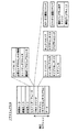
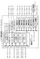
図3に、ソフトウェアセルの構成の一例を示す。この例のソフトウェアセルは、全体として、送信元ID、送信先ID、応答先ID、セルインターフェース、DMAコマンド、プログラム、およびデータによって構成される。 FIG. 3 shows an example of the configuration of the software cell. The software cell in this example is composed of a transmission source ID, a transmission destination ID, a response destination ID, a cell interface, a DMA command, a program, and data as a whole.
送信元IDには、ソフトウェアセルの送信元である情報処理装置のネットワークアドレスおよび情報処理装置ID、さらに、その情報処理装置内の情報処理コントローラが備えるメインプロセッサ21および各サブプロセッサ23の識別子(メインプロセッサIDおよびサブプロセッサID)が含まれる。
The transmission source ID includes the network address and information processing device ID of the information processing device that is the transmission source of the software cell, and the identifiers of the
送信先IDおよび応答先IDには、それぞれ、ソフトウェアセルの送信先である情報処理装置、およびソフトウェアセルの実行結果の応答先である情報処理装置についての、同じ情報が含まれる。 The transmission destination ID and the response destination ID include the same information about the information processing device that is the transmission destination of the software cell and the information processing device that is the response destination of the execution result of the software cell, respectively.
セルインターフェースは、ソフトウェアセルの利用に必要な情報であり、グローバルID、必要なサブプロセッサの情報、サンドボックスサイズ、および前回のソフトウェアセルIDから構成される。 The cell interface is information necessary for using the software cell, and includes a global ID, necessary sub-processor information, a sandbox size, and a previous software cell ID.
グローバルIDは、ネットワーク全体を通して当該のソフトウェアセルを一意的に識別するものであり、送信元ID、およびソフトウェアセルの作成または送信の日時(日付および時刻)に基づいて作成される。 The global ID uniquely identifies the software cell throughout the network, and is created based on the transmission source ID and the date and time (date and time) of creation or transmission of the software cell.
必要なサブプロセッサの情報は、当該ソフトウェアセルの実行に必要なサブプロセッサの数が設定される。サンドボックスサイズは、当該ソフトウェアセルの実行に必要なメインメモリ26内およびサブプロセッサ23のLS24内のメモリ量が設定される。
In the necessary sub-processor information, the number of sub-processors necessary for executing the software cell is set. The sandbox size is set with the amount of memory in the main memory 26 and the
前回のソフトウェアセルIDは、ストリーミングデータなどのシーケンシャルな実行を要求する1グループのソフトウェアセル内の、前回のソフトウェアセルの識別子である。 The previous software cell ID is an identifier of the previous software cell in a group of software cells that request sequential execution of streaming data or the like.
ソフトウェアセルの実行セクションは、DMAコマンド、プログラムおよびデータから構成される。DMAコマンドには、プログラムの起動に必要な一連のDMAコマンドが含まれ、プログラムには、サブプロセッサ23によって実行されるサブプロセッサプログラムが含まれる。ここでのデータは、このサブプロセッサプログラムを含むプログラムによって処理されるデータである。
The execution section of the software cell is composed of DMA commands, programs and data. The DMA command includes a series of DMA commands necessary for starting the program, and the program includes a sub processor program executed by the
さらに、DMAコマンドには、ロードコマンド、キックコマンド、機能プログラム実行コマンド、ステータス要求コマンド、およびステータス返信コマンドが含まれる。 Further, the DMA command includes a load command, a kick command, a function program execution command, a status request command, and a status return command.
ロードコマンドは、メインメモリ26内の情報をサブプロセッサ23内のLS24にロードするコマンドであり、ロードコマンド自体のほかに、メインメモリアドレス、サブプロセッサIDおよびLSアドレスを含む。メインメモリアドレスは、情報のロード元であるメインメモリ26内の所定領域のアドレスを示す。サブプロセッサIDおよびLSアドレスは、情報のロード先であるサブプロセッサ23の識別子およびLS24のアドレスを示す。
The load command is a command for loading information in the main memory 26 into the
キックコマンドは、プログラムの実行を開始するコマンドであり、キックコマンド自体のほかに、サブプロセッサIDおよびプログラムカウンタを含む。サブプロセッサIDは、キック対象のサブプロセッサ23を識別し、プログラムカウンタは、プログラム実行用プログラムカウンタのためのアドレスを与える。
The kick command is a command for starting execution of the program, and includes a sub processor ID and a program counter in addition to the kick command itself. The sub processor ID identifies the
機能プログラム実行コマンドは、後述のように、ある情報処理装置が他の情報処理装置に対して、機能プログラムの実行を要求するコマンドである。機能プログラム実行コマンドを受信した情報処理装置内の情報処理コントローラは、後述の機能プログラムIDによって、起動すべき機能プログラムを識別する。 As will be described later, the function program execution command is a command for requesting execution of a function program from another information processing apparatus to another information processing apparatus. The information processing controller in the information processing apparatus that has received the function program execution command identifies a function program to be activated by a function program ID described later.
ステータス要求コマンドは、送信先IDで示される情報処理装置の現在の状態(状況)に関する装置情報を、応答先IDで示される情報処理装置宛てに送信することを要求するコマンドである。機能プログラムについては後述するが、図6に示す情報処理装置のメインメモリ26が記憶するソフトウェアの構成図において機能プログラムにカテゴライズされるプログラムである。機能プログラムは、メインメモリ26にロードされ、メインプロセッサ21により実行される。
The status request command is a command for requesting transmission of device information related to the current state (situation) of the information processing device indicated by the transmission destination ID to the information processing device indicated by the response destination ID. Although the function program will be described later, the program is categorized into the function program in the software configuration diagram stored in the main memory 26 of the information processing apparatus illustrated in FIG. 6. The function program is loaded into the main memory 26 and executed by the
ステータス返信コマンドは、上記のステータス要求コマンドを受信した情報処理装置が、自身の装置情報を当該ステータス要求コマンドに含まれる応答先IDで示される情報処理装置に応答するコマンドである。ステータス返信コマンドは、実行セクションのデータ領域に装置情報を格納する。 The status reply command is a command in which the information processing apparatus that has received the status request command responds to the information processing apparatus indicated by the response destination ID included in the status request command with its own apparatus information. The status reply command stores device information in the data area of the execution section.
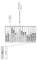
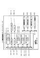
図4に、DMAコマンドがステータス返信コマンドである場合におけるソフトウェアセルのデータ領域の構造を示す。 FIG. 4 shows the structure of the data area of the software cell when the DMA command is a status return command.
情報処理装置IDは、情報処理コントローラを備える情報処理装置を識別するための識別子であり、ステータス返信コマンドを送信する情報処理装置のIDを示す。情報処理装置IDは、電源投入時、その情報処理装置内の情報処理コントローラに含まれるメインプロセッサ21によって、電源投入時の日時、情報処理装置のネットワークアドレスおよび情報処理装置内の情報処理コントローラに含まれるサブプロセッサ23の数などに基づいて生成される。
The information processing device ID is an identifier for identifying the information processing device including the information processing controller, and indicates the ID of the information processing device that transmits the status reply command. The information processing apparatus ID is included in the information processing controller in the information processing apparatus by the
情報処理装置種別IDには、当該の情報処理装置の特徴を表す値が含まれる。情報処理装置の特徴とは、例えば、後述のハードディスクレコーダ、PDA(Personal Digital Assistants)、ポータブルCD(Compact Disc)プレーヤなどである。また、情報処理装置種別IDは、映像音声記録、映像音声再生など、情報処理装置の機能を表すものであってもよい。情報処理装置の特徴や機能を表す値は、あらかじめ決定されているものとし、情報処理装置種別IDを読み出すことにより、当該情報処理装置の特徴や機能を把握することが可能である。 The information processing device type ID includes a value representing the characteristics of the information processing device. The characteristics of the information processing apparatus include, for example, a hard disk recorder, a PDA (Personal Digital Assistant), a portable CD (Compact Disc) player, and the like, which will be described later. The information processing device type ID may represent a function of the information processing device such as video / audio recording or video / audio reproduction. It is assumed that values representing the characteristics and functions of the information processing apparatus are determined in advance, and it is possible to grasp the characteristics and functions of the information processing apparatus by reading the information processing apparatus type ID.
MS(マスター/スレーブ)ステータスは、後述のように情報処理装置がマスター装置またはスレーブ装置のいずれで動作しているかを表すもので、これが0に設定されている場合にはマスター装置として動作していることを示し、1に設定されている場合にはスレーブ装置として動作していることを示す。 The MS (master / slave) status indicates whether the information processing apparatus is operating as a master apparatus or a slave apparatus, as will be described later. When this is set to 0, it operates as a master apparatus. If it is set to 1, it indicates that it is operating as a slave device.
メインプロセッサ動作周波数は、情報処理コントローラ内のメインプロセッサ21の動作周波数を表す。メインプロセッサ使用率は、メインプロセッサ21で現在動作している全てのプログラムについての、メインプロセッサ21での使用率を表す。メインプロセッサ使用率は、対象メインプロセッサの全処理能力に対する使用中の処理能力の比率を表した値で、例えばプロセッサ処理能力評価のための単位であるMIPSを単位として算出され、または単位時間あたりのプロセッサ使用時間に基づいて算出される。後述のサブプロセッサ使用率についても同様である。
The main processor operating frequency represents the operating frequency of the
サブプロセッサ数は、当該の情報処理コントローラが備えるサブプロセッサ23の数を表す。サブプロセッサIDは、当該の情報処理コントローラ内の各サブプロセッサ23を識別するための識別子である。
The number of sub-processors represents the number of
サブプロセッサステータスは、各サブプロセッサ23の状態を表すものであり、unused,reserved,busyなどの状態がある。unusedは、当該のサブプロセッサが現在使用されてなく、使用の予約もされていないことを示す。reservedは、現在は使用されていないが、使用が予約されている状態を示す。busyは、現在使用中であることを示す。
The sub processor status represents the state of each
サブプロセッサ使用率は、当該のサブプロセッサで現在実行している、または当該のサブプロセッサに実行が予約されているプログラムについての、当該サブプロセッサでの使用率を表す。すなわち、サブプロセッサ使用率は、サブプロセッサステータスがbusyである場合には、現在の使用率を示し、サブプロセッサステータスがreservedである場合には、後に使用される予定の推定使用率を示す。 The sub-processor usage rate represents the usage rate of the sub-processor for a program that is currently being executed by the sub-processor or that is reserved for execution by the sub-processor. That is, the sub processor usage rate indicates the current usage rate when the sub processor status is busy, and indicates the estimated usage rate that is to be used later when the sub processor status is reserved.
サブプロセッサID、サブプロセッサステータスおよびサブプロセッサ使用率は、一つのサブプロセッサ23に対して一組設定され、一つの情報処理コントローラ内のサブプロセッサ23の数の組数だけ設定される。
One set of sub-processor ID, sub-processor status, and sub-processor usage rate is set for one
メインメモリ総容量およびメインメモリ使用量は、それぞれ、当該の情報処理コントローラに接続されているメインメモリ26の総容量および現在使用中の容量を表す。 The main memory total capacity and the main memory usage amount represent the total capacity and the currently used capacity of the main memory 26 connected to the information processing controller, respectively.
外部記録部数は、当該の情報処理コントローラに接続されている外部記録部28の数を表す。外部記録部IDは、当該の情報処理コントローラに接続されている外部記録部28を一意的に識別する情報である。外部記録部種別IDは、当該の外部記録部の種類(例えば、ハードディスク、CD±RW、DVD±RW、メモリディスク、SRAM、ROMなど)を表す。 The number of external recording units represents the number of external recording units 28 connected to the information processing controller. The external recording unit ID is information that uniquely identifies the external recording unit 28 connected to the information processing controller. The external recording unit type ID represents the type of the external recording unit (for example, hard disk, CD ± RW, DVD ± RW, memory disk, SRAM, ROM, etc.).
外部記録部総容量および外部記録部使用量は、それぞれ、外部記録部IDによって識別される外部記録部28の総容量および現在使用中の容量を表す。 The external recording unit total capacity and the external recording unit usage amount represent the total capacity and the currently used capacity of the external recording unit 28 identified by the external recording unit ID, respectively.
外部記録部ID、外部記録部種別ID、外部記録部総容量および外部記録部使用量は、一つの外部記録部28に対して一組設定され、当該の情報処理コントローラに接続されている外部記録部28の数の組数だけ設定される。すなわち、一つの情報処理コントローラに複数の外部記録部が接続されている場合、各々の外部記録部には異なる外部記録部IDが割り当てられ、外部記録部種別ID、外部記録部総容量および外部記録部使用量も別々に管理される。 The external recording unit ID, the external recording unit type ID, the external recording unit total capacity, and the external recording unit usage amount are set as a set for one external recording unit 28 and connected to the information processing controller. The number of sets of the number of units 28 is set. That is, when a plurality of external recording units are connected to one information processing controller, different external recording unit IDs are assigned to the respective external recording units, the external recording unit type ID, the external recording unit total capacity, and the external recording unit. Department usage is also managed separately.
(1−4.ソフトウェアセルの実行:図3および図4)
ある情報処理装置内の情報処理コントローラに含まれるメインプロセッサ21は、以上のような構成のソフトウェアセルを生成し、ネットワーク9を介して他の情報処理装置に送信する。送信元の情報処理装置、送信先の情報処理装置、応答先の情報処理装置、および各装置内の情報処理コントローラは、それぞれ、上記の送信元ID、送信先IDおよび応答先IDによって識別される。
(1-4. Execution of software cell: FIGS. 3 and 4)
The
ソフトウェアセルを受信した情報処理装置内の情報処理コントローラに含まれるメインプロセッサ21は、そのソフトウェアセルをメインメモリ26に格納する。さらに、送信先のメインプロセッサ21は、ソフトウェアセルを読み出し、それに含まれるDMAコマンドを処理する。
The
具体的に、送信先のメインプロセッサ21は、まず、ロードコマンドを実行する。これによって、ロードコマンドで指示されたメインメモリアドレスから、ロードコマンドに含まれるサブプロセッサIDおよびLSアドレスで特定されるサブプロセッサ内のLS24の所定領域に、情報がロードされる。この場合のロードされる情報は、受信したソフトウェアセルに含まれるサブプロセッサプログラムまたはデータ、あるいはその他の指示されたデータである。
Specifically, the transmission destination
次に、メインプロセッサ21は、キックコマンドを、これに含まれるサブプロセッサIDで指示されたサブプロセッサに、同様にキックコマンドに含まれるプログラムカウンタと共に出力する。
Next, the
指示されたサブプロセッサは、そのキックコマンドおよびプログラムカウンタに従って、サブプロセッサプログラムを実行する。そして、実行結果をメインメモリ26に格納した後、実行を完了したことをメインプロセッサ21に通知する。
The instructed sub processor executes the sub processor program according to the kick command and the program counter. After the execution result is stored in the main memory 26, the
なお、送信先の情報処理装置内の情報処理コントローラにおいてソフトウェアセルを実行するプロセッサはサブプロセッサ23に限るものではなく、メインプロセッサ21がソフトウェアセルに含まれる機能プログラムなどのメインメモリ用プログラムを実行するように指定することも可能である。
The processor that executes the software cell in the information processing controller in the information processing apparatus of the transmission destination is not limited to the sub-processor 23, and the
この場合には、送信元の情報処理装置は、送信先の情報処理装置宛てに、サブプロセッサプログラムの代わりに、メインメモリ用プログラムおよびそれによって処理されるデータを含み、DMAコマンドがロードコマンドであるソフトウェアセルを送信し、メインメモリ26にメインメモリ用プログラムおよびそれによって処理されるデータを記憶させる。次に、送信元の情報処理装置は、送信先の情報処理装置宛てに、送信先の情報処理装置内の情報処理コントローラについてのメインプロセッサID、メインメモリアドレス、メインメモリ用プログラムを識別するための機能プログラムIDなどの識別子、およびプログラムカウンタを含み、DMAコマンドがキックコマンドまたは機能プログラム実行コマンドであるソフトウェアセルを送信して、メインプロセッサ21に当該メインメモリ用プログラムを実行させる。
In this case, the transmission source information processing apparatus includes a main memory program and data processed thereby instead of the sub-processor program, and the DMA command is a load command. The software cell is transmitted, and the main memory 26 stores the main memory program and data processed thereby. Next, the transmission source information processing apparatus identifies the main processor ID, the main memory address, and the main memory program for the information processing controller in the transmission destination information processing apparatus to the transmission destination information processing apparatus. A software cell that includes an identifier such as a function program ID and a program counter and whose DMA command is a kick command or a function program execution command is transmitted to cause the
以上のように、この発明のネットワークシステムでは、送信元の情報処理装置は、サブプロセッサプログラムまたはメインメモリ用プログラムをソフトウェアセルによって送信先の情報処理装置に送信するとともに、当該サブプロセッサプログラムを送信先の情報処理装置内の情報処理コントローラに含まれるサブプロセッサ23にロードさせ、当該サブプロセッサプログラムまたは当該メインメモリ用プログラムを送信先の情報処理装置に実行させることができる。
As described above, in the network system of the present invention, the transmission source information processing apparatus transmits the sub processor program or the main memory program to the transmission destination information processing apparatus by the software cell, and transmits the sub processor program to the transmission destination. It is possible to load the
送信先の情報処理装置内の情報処理コントローラでは、受信したソフトウェアセルに含まれるプログラムがサブプロセッサプログラムである場合には、当該サブプロセッサプログラムを指定されたサブプロセッサにロードさせる。そして、ソフトウェアセルに含まれるサブプロセッサプログラムまたはメインメモリ用プログラムを実行させる。 When the program included in the received software cell is a sub processor program, the information processing controller in the transmission destination information processing apparatus loads the sub processor program to the designated sub processor. Then, the sub processor program or the main memory program included in the software cell is executed.
したがって、ユーザが送信先の情報処理装置を操作しなくても自動的に、当該サブプロセッサプログラムまたは当該メインメモリ用プログラムを送信先の情報処理装置内の情報処理コントローラに実行させることができる。 Therefore, even if the user does not operate the transmission destination information processing apparatus, the sub processor program or the main memory program can be automatically executed by the information processing controller in the transmission destination information processing apparatus.
このようにして、上記の情報処理装置は、自装置内にサブプロセッサプログラムまたは機能プログラムなどのメインメモリ用プログラムを有していない場合には、ネットワークに接続された他の情報処理装置から、それらを取得することができる。さらに、各サブプロセッサ間ではDMA方式によりデータ転送を行い、また上述したサンドボックスを使用することによって、一つの情報処理コントローラ内でデータを多段階に処理する必要がある場合でも、高速かつ高セキュリティに処理を実行することができる。 In this way, when the information processing apparatus does not have a main memory program such as a sub-processor program or a function program in its own apparatus, the information processing apparatus receives the information from other information processing apparatuses connected to the network. Can be obtained. Furthermore, data transfer is performed between each sub-processor using the DMA method, and the above-described sandbox is used, so that even if it is necessary to process data in multiple stages within one information processing controller, high speed and high security are achieved. The process can be executed.
〔2.情報処理装置間の分散処理の例:図5〜図12〕
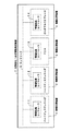
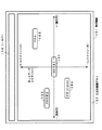
ソフトウェアセルの使用による分散処理の結果、図5の上段に示すようにネットワーク9に接続されている情報処理装置1,2,3および4は、図5の下段に示すように、仮想的な1台の情報処理装置7として動作する。ただし、そのためには、以下のような構成によって、以下のような処理が実行される必要がある。
[2. Example of distributed processing between information processing apparatuses: FIGS. 5 to 12]
As a result of the distributed processing using the software cell, the
(2−1.システムのソフトウェア構成とプログラムのロード:図5および図6)
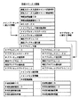
図6に、個々の情報処理装置内のメインメモリ26が記憶するソフトウェアの構成を示す。これらのソフトウェア(プログラム)は、情報処理装置に電源が投入される前においては、当該の情報処理装置内の情報処理コントローラに接続される外部記録部28に記録されているものである。
(2-1. System Software Configuration and Program Loading: FIGS. 5 and 6)
FIG. 6 shows the configuration of software stored in the main memory 26 in each information processing apparatus. These software (programs) are recorded in the external recording unit 28 connected to the information processing controller in the information processing apparatus before the information processing apparatus is turned on.
各プログラムは、機能または特徴によって、制御プログラム、機能プログラムおよびデバイスドライバにカテゴライズされる。 Each program is categorized into a control program, a function program, and a device driver by function or feature.
制御プログラムは、各情報処理装置が同じものを備え、各情報処理コントローラ内のメインプロセッサ21が実行するもので、後述のMS(マスター/スレーブ)マネージャおよび能力交換プログラムを含む。
The control program is the same for each information processing apparatus and is executed by the
機能プログラムは、メインプロセッサ21が実行するもので、記録用、再生用、素材検索用など、情報処理装置ごとに情報処理装置に応じたものが備えられる。
The function program is executed by the
デバイスドライバは、情報処理装置の入出力(送受信)用で、放送受信、モニタ出力、ビットストリーム入出力、ネットワーク入出力など、情報処理装置ごとに情報処理装置に応じたものが備えられる。 The device driver is used for input / output (transmission / reception) of the information processing apparatus, and is provided for each information processing apparatus such as broadcast reception, monitor output, bit stream input / output, and network input / output.
ケーブルの差し込みなどによって情報処理装置が物理的にネットワーク9に接続された状態で、情報処理装置に主電源が投入され、情報処理装置が電気的・機能的にもネットワーク9に接続されると、その情報処理装置内のメインプロセッサ21は、制御プログラムに属する各プログラム、およびデバイスドライバに属する各プログラムを、メインメモリ26にロードする。
When the information processing apparatus is physically connected to the
ロード手順としては、メインプロセッサ21は、まず、DC27に読み出し命令を実行させることによって、外部記録部28からプログラムを読み出し、次に、DMAC25に書き込み命令を実行させることによって、そのプログラムをメインメモリ26に書き込む。
As a loading procedure, the
機能プログラムに属する各プログラムについては、必要なときに必要なプログラムだけをロードするように構成してもよく、または、他のカテゴリに属するプログラムと同様に、主電源投入直後に各プログラムをロードするように構成してもよい。 As for each program belonging to the function program, it may be configured to load only the necessary program when necessary, or like the programs belonging to other categories, each program is loaded immediately after the main power is turned on. You may comprise as follows.
この場合、機能プログラムに属する各プログラムは、ネットワーク9に接続された全ての情報処理装置の外部記録部28に記録されている必要はなく、いずれか一つの情報処理装置の外部記録部28に記録されていれば、上述した方法によって他の情報処理装置からロードすることができるので、結果的に図5の下段に示すように、仮想的な1台の情報処理装置7として機能プログラムを実行することができる。
In this case, each program belonging to the function program does not need to be recorded in the external recording unit 28 of all information processing apparatuses connected to the
上述したようにメインプロセッサ21によって処理される機能プログラムは、サブプロセッサ23によって処理されるサブプロセッサプログラムと連携動作する場合がある。そこで、メインプロセッサ21が外部記録部28から機能プログラムを読み出し、メインメモリ26に書き込む際に対象となる機能プログラムと連携動作するサブプロセッサプログラムが存在する場合には、当該サブプロセッサプログラムも併せて同じメインメモリ26に書き込むものとする。
As described above, the function program processed by the
この場合、機能プログラムと連携動作するサブプロセッサプログラムは、1個であることもあるが、複数個であることもある。複数個である場合には、連携動作する全てのサブプロセッサプログラムをメインメモリ26に書き込むことになる。メインメモリ26に書き込まれたサブプロセッサプログラムは、その後、サブプロセッサ23内のLS24に書き込まれ、メインプロセッサ21によって処理される機能プログラムと連携動作する。
In this case, there may be one sub processor program that operates in cooperation with the function program, but there may be a plurality of sub processor programs. If there are a plurality of programs, all the sub-processor programs that operate in cooperation are written in the main memory 26. The sub processor program written in the main memory 26 is then written in the
図3のソフトウェアセルに示したように、機能プログラムには、プログラムごとにプログラムを一意的に識別できる識別子が、機能プログラムIDとして割り当てられる。機能プログラムIDは、機能プログラムの作成の段階で、作成日時や情報処理装置IDなどから決定される。 As shown in the software cell of FIG. 3, an identifier that can uniquely identify the program for each program is assigned to the function program as the function program ID. The function program ID is determined from the creation date and time, the information processing apparatus ID, and the like at the stage of creating the function program.
サブプロセッサプログラムにも、サブプロセッサプログラムIDが割り当てられ、これによりサブプロセッサプログラムを一意的に識別することができる。割り当てられるサブプロセッサプログラムIDは、連携動作する機能プログラムの機能プログラムIDと関連性のある識別子、例えば機能プログラムIDを親番号とした上で最後尾に枝番号を付加したものでもよく、または、連携動作する機能プログラムの機能プログラムIDとは関連性のない識別子でもよい。いずれにしても、機能プログラムとサブプロセッサプログラムが連携動作する場合には、両者とも相手のプログラムIDを自プログラム内に記憶しておく必要がある。機能プログラムが複数個のサブプロセッサプログラムと連携動作する場合にも、当該機能プログラムは、その複数個の全てのサブプロセッサプログラムのサブプロセッサプログラムIDを記憶しておくことになる。 A sub processor program ID is also assigned to the sub processor program, whereby the sub processor program can be uniquely identified. The assigned sub processor program ID may be an identifier related to the function program ID of the function program that operates in cooperation, for example, the function program ID as a parent number and a branch number added at the end, or An identifier that is not related to the function program ID of the function program to be operated may be used. In any case, when the function program and the sub processor program operate in cooperation, it is necessary to store the other party's program ID in the own program. Even when the function program operates in cooperation with a plurality of sub processor programs, the function program stores the sub processor program IDs of all the plurality of sub processor programs.
メインプロセッサ21は、自身が動作する情報処理装置の装置情報(装置の種別、能力、動作状態、装置が有する資源などの、装置に関する情報)を格納するための領域をメインメモリ26に確保し、当該情報を自装置の装置情報テーブルとして記録する。この場合の装置情報は、具体的には、図4に示した情報処理装置ID以下の各情報である。
The
(2−2.システムにおけるマスター/スレーブの決定:図5および図6)
上述したネットワークシステムでは、ある情報処理装置への主電源投入時、その情報処理装置のメインプロセッサ21は、MS(マスター/スレーブ)マネージャをメインメモリ26にロードし、実行する。
(2-2. Determination of Master / Slave in the System: FIGS. 5 and 6)
In the network system described above, when the main power supply to a certain information processing apparatus is turned on, the
MSマネージャは、自身が動作する情報処理装置がネットワーク9に接続されていることを検知すると、同じネットワーク9に接続されている他の情報処理装置の存在を確認する。ここでの「接続」または「存在」は、上述したように、情報処理装置が物理的にネットワーク9に接続されているだけでなく、電気的・機能的にもネットワーク9に接続されていることを示す。
When the MS manager detects that the information processing apparatus on which it operates is connected to the
MSマネージャが同じネットワーク9上に他の情報処理装置が存在することを確認する方法を以下に示す。
A method for the MS manager to confirm that another information processing apparatus exists on the
MSマネージャは、DMAコマンドがステータス要求コマンドであり、送信元IDおよび応答先IDが自装置で、送信先IDを特定しないソフトウェアセルを生成して、自装置が接続されたネットワーク上に送信して、ネットワーク接続確認用のタイマーを設定する。タイマーのタイムアウト時間は、例えば10分とされる。 The MS manager generates a software cell in which the DMA command is a status request command, the transmission source ID and the response destination ID are the own device, and does not specify the transmission destination ID, and transmits the software cell to the network to which the own device is connected. Set a timer for checking the network connection. The timeout time of the timer is, for example, 10 minutes.
当該ネットワーク上に他の情報処理装置が存在する場合、その他装置は、上記ステータス要求コマンドのソフトウェアセルを受信し、上記応答先IDで特定されるステータス要求コマンドを発行した情報処理装置に対して、DMAコマンドがステータス返信コマンドで、かつデータとして自身(その他装置)の装置情報を含むソフトウェアセルを送信する。このステータス返信コマンドのソフトウェアセルには、少なくとも当該他装置を特定する情報(情報処理装置ID、メインプロセッサに関する情報、サブプロセッサに関する情報など)および当該他装置のMSステータスが含まれる。 When there is another information processing apparatus on the network, the other apparatus receives the software cell of the status request command and issues the status request command specified by the response destination ID to the information processing apparatus The DMA command is a status reply command, and a software cell including device information of itself (other device) is transmitted as data. The software cell of this status reply command includes at least information for identifying the other device (information processing device ID, information on the main processor, information on the sub processor, etc.) and the MS status of the other device.
ステータス要求コマンドを発行した情報処理装置のMSマネージャは、上記ネットワーク接続確認用のタイマーがタイムアウトするまで、当該ネットワーク上の他装置から送信されるステータス返信コマンドのソフトウェアセルの受信を監視する。その結果、MSステータス=0(マスター装置)を示すステータス返信コマンドが受信された場合には、自装置の装置情報テーブルにおけるMSステータスを1に設定する。これによって、当該装置はスレーブ装置となる。 The MS manager of the information processing apparatus that has issued the status request command monitors the reception of the software cell of the status reply command transmitted from another apparatus on the network until the timer for network connection confirmation times out. As a result, when the status reply command indicating the MS status = 0 (master device) is received, the MS status in the device information table of the own device is set to 1. As a result, the device becomes a slave device.
一方、上記ネットワーク接続確認用のタイマーがタイムアウトするまでの間にステータス返信コマンドが全く受信されなかった場合、またはMSステータス=0(マスター装置)を示すステータス返信コマンドが受信されなかった場合には、自装置の装置情報テーブルにおけるMSステータスを0に設定する。これによって、当該装置はマスター装置となる。 On the other hand, if no status reply command is received before the network connection confirmation timer times out, or if no status reply command indicating MS status = 0 (master device) is received, The MS status in the device information table of the own device is set to 0. This makes the device a master device.
すなわち、いずれの装置もネットワーク9に接続されていない状態、またはネットワーク9上にマスター装置が存在しない状態において、新たな情報処理装置がネットワーク9に接続されると、当該装置は自動的にマスター装置として設定される。一方、ネットワーク9上に既にマスター装置が存在する状態において、新たな情報処理装置がネットワーク9に接続されると、当該装置は自動的にスレーブ装置として設定される。
That is, if no information processing apparatus is connected to the
マスター装置およびスレーブ装置のいずれについても、MSマネージャは、定期的にステータス要求コマンドをネットワーク9上の他装置に送信してステータス情報を照会することにより、他装置の状況を監視する。その結果、ネットワーク9に接続されている情報処理装置の主電源が遮断され、またはネットワーク9から情報処理装置が切り離されることにより、あらかじめ判定用に設定された所定期間内に特定の他装置からステータス返信コマンドが返信されなかった場合や、ネットワーク9に新たな情報処理装置が接続された場合など、ネットワーク9の接続状態に変化があった場合には、その情報を後述の能力交換プログラムに通知する。
For both the master device and the slave device, the MS manager periodically monitors the status of the other device by sending a status request command to the other device on the
(2−3.能力交換による装置情報の取得:図5および図6)
メインプロセッサ21は、MSマネージャから、ネットワーク9上の他装置の照会および自装置のMSステータスの設定完了の通知を受けると、能力交換プログラムを実行する。
(2-3. Acquisition of device information by capability exchange: FIGS. 5 and 6)
When the
能力交換プログラムは、自装置がマスター装置である場合には、ネットワーク9に接続されている全ての他装置の装置情報、すなわち各スレーブ装置の装置情報を取得する。
When the own device is a master device, the capability exchange program acquires device information of all other devices connected to the
他装置の装置情報の取得は、上述したように、DMAコマンドがステータス要求コマンドであるソフトウェアセルを生成して他装置に送信し、その後、DMAコマンドがステータス返信コマンドで、かつデータとして他装置の装置情報を含むソフトウェアセルを他装置から受信することによって可能である。 As described above, the device information of another device is generated by generating a software cell in which the DMA command is a status request command and transmitting it to the other device. Thereafter, the DMA command is a status return command and data of the other device. This is possible by receiving a software cell containing device information from another device.
能力交換プログラムは、マスター装置である自装置の装置情報テーブルと同様に、ネットワーク9に接続されている全ての他装置(各スレーブ装置)の装置情報を格納するための領域を自装置のメインメモリ26に確保し、これら情報を他装置(スレーブ装置)の装置情報テーブルとして記録する。
Similar to the device information table of the own device that is the master device, the capability exchange program sets an area for storing device information of all other devices (each slave device) connected to the
すなわち、マスター装置のメインメモリ26には、自装置を含むネットワーク9に接続されている全ての情報処理装置の装置情報が、装置情報テーブルとして記録される。
That is, the device information of all information processing devices connected to the
一方、能力交換プログラムは、自装置がスレーブ装置である場合には、ネットワーク9に接続されている全ての他装置の装置情報、すなわちマスター装置および自装置以外の各スレーブ装置の装置情報を取得し、これら装置情報に含まれる情報処理装置IDおよびMSステータスを、自装置のメインメモリ26に記録する。
On the other hand, when the own device is a slave device, the capability exchange program obtains device information of all other devices connected to the
すなわち、スレーブ装置のメインメモリ26には、自装置の装置情報が、装置情報テーブルとして記録されるとともに、自装置以外のネットワーク9に接続されているマスター装置および各スレーブ装置についての情報処理装置IDおよびMSステータスが、別の装置情報テーブルとして記録される。
That is, the device information of the own device is recorded as a device information table in the main memory 26 of the slave device, and the master device connected to the
また、マスター装置およびスレーブ装置のいずれについても、能力交換プログラムは、上記のようにMSマネージャから、新たにネットワーク9に情報処理装置が接続されたことが通知されたときには、その情報処理装置の装置情報を取得し、上述したようにメインメモリ26に記録する。
Further, in both the master device and the slave device, when the capability exchange program is notified from the MS manager that the information processing device is newly connected to the
なお、MSマネージャおよび能力交換プログラムは、メインプロセッサ21で実行されることに限らず、いずれかのサブプロセッサ23で実行されてもよい。また、MSマネージャおよび能力交換プログラムは、情報処理装置の主電源が投入されている間は常時動作する常駐プログラムであることが望ましい。
Note that the MS manager and the capability exchange program are not limited to being executed by the
(2−4.情報処理装置がネットワークから切断された場合:図5および図6)
マスター装置およびスレーブ装置のいずれについても、能力交換プログラムは、上記のようにMSマネージャから、ネットワーク9に接続されている情報処理装置の主電源が遮断され、またはネットワーク9から情報処理装置が切り離されたことが通知されたときには、その情報処理装置の装置情報テーブルを自装置のメインメモリから削除する。
(2-4. When the information processing apparatus is disconnected from the network: FIGS. 5 and 6)
For both the master device and the slave device, the capability exchange program causes the MS manager to cut off the main power supply of the information processing device connected to the
さらに、このようにネットワーク9から切断された情報処理装置がマスター装置である場合には、以下のような方法によって、新たにマスター装置が決定される。
Further, when the information processing apparatus disconnected from the
具体的に、例えば、ネットワーク9から切断されていない情報処理装置は、それぞれ、自装置および他装置の情報処理装置IDを数値に置き換えて、自装置の情報処理装置IDを他装置の情報処理装置IDと比較し、自装置の情報処理装置IDがネットワーク9から切断されていない情報処理装置中で最小である場合、そのスレーブ装置は、マスター装置に移行して、MSステータスを0に設定し、マスター装置として、上述したように、ネットワーク9に接続されている全ての他装置(各スレーブ装置)の装置情報を取得して、メインメモリ26に記録する。
Specifically, for example, each of the information processing apparatuses that are not disconnected from the
(2−5.装置情報に基づく情報処理装置間の分散処理:図7および図8)
図5の下段に示したようにネットワーク9に接続されている複数の情報処理装置1,2,3および4を仮想的な1台の情報処理装置7として動作させるためには、マスター装置がユーザの操作およびスレーブ装置の動作状態などを把握する必要がある。
(2-5. Distributed processing between information processing devices based on device information: FIGS. 7 and 8)
As shown in the lower part of FIG. 5, in order for a plurality of
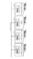
図7に、4台の情報処理装置が仮想的な1台の情報処理装置7として動作する様子を示す。情報処理装置1がマスター装置として動作し、情報処理装置2,3および4がスレーブ装置A,BおよびCとして動作しているものとする。
FIG. 7 shows a state in which four information processing apparatuses operate as one virtual
ユーザがネットワーク9に接続されている情報処理装置を操作した場合、操作対象がマスター装置1であれば、その操作情報は、マスター装置1において直接把握され、操作対象がスレーブ装置であれば、その操作情報は、操作されたスレーブ装置からマスター装置1に送信される。すなわち、ユーザの操作対象がマスター装置1とスレーブ装置のいずれであるかにかかわらず、その操作情報は常にマスター装置1において把握される。操作情報の送信は、例えば、DMAコマンドが操作情報送信コマンドであるソフトウェアセルによって行われる。
When the user operates an information processing device connected to the
そして、マスター装置1内の情報処理コントローラ11に含まれるメインプロセッサ21−1は、その操作情報に従って、実行する機能プログラムを選択する。その際、必要であれば、マスター装置1内の情報処理コントローラ11に含まれるメインプロセッサ21−1は、上記の方法によって自装置の外部記録部28−1または28−2からメインメモリ26−1に機能プログラムをロードするが、他の情報処理装置(スレーブ装置)がマスター装置1に機能プログラムを送信してもよい。
Then, the main processor 21-1 included in the
機能プログラムには、その実行単位ごとに必要となる、図4に示した各情報として表される情報処理装置種別ID、メインプロセッサまたはサブプロセッサの処理能力、メインメモリ使用量、外部記録部に関する条件などの、装置に関する要求スペックが規定されている。 In the function program, information processing device type IDs represented as information shown in FIG. 4, main processor or sub-processor processing capacity, main memory usage, and conditions related to the external recording unit are required for each execution unit. The required specifications regarding the device are defined.
マスター装置1内の情報処理コントローラ11に含まれるメインプロセッサ21−1は、各機能プログラムについて必要となる上記要求スペックを読み出す。また、あらかじめ能力交換プログラムによってメインメモリ26−1に記録された装置情報テーブルを参照し、各情報処理装置の装置情報を読み出す。この場合の装置情報は、図4に示した情報処理装置ID以下の各情報を示し、メインプロセッサ、サブプロセッサ、メインメモリおよび外部記録部に関する情報である。
The main processor 21-1 included in the
マスター装置1内の情報処理コントローラ11に含まれるメインプロセッサ21−1は、ネットワーク9に接続されている各情報処理装置の上記装置情報と、機能プログラム実行に必要となる上記要求スペックとを順次比較する。
The main processor 21-1 included in the
そして、例えば、機能プログラムが録画機能を必要とする場合には、情報処理装置種別IDに基づいて、録画機能を有する情報処理装置のみを特定して抽出する。さらに、機能プログラムを実行するために必要なメインプロセッサまたはサブプロセッサの処理能力、メインメモリ使用量、外部記録部に関する条件を確保できるスレーブ装置を、実行要求候補装置として特定する。複数の実行要求候補装置が特定された場合には、そのうちの一つを選択する。 For example, when the function program requires a recording function, only the information processing apparatus having the recording function is specified and extracted based on the information processing apparatus type ID. Furthermore, a slave device that can secure the conditions regarding the processing capability of the main processor or sub processor, the amount of main memory used, and the external recording unit necessary for executing the function program is specified as an execution request candidate device. When a plurality of execution request candidate devices are specified, one of them is selected.
実行要求先のスレーブ装置が特定されたら、マスター装置1内の情報処理コントローラ11に含まれるメインプロセッサ21−1は、その特定されたスレーブ装置について、自装置内の情報処理コントローラ11に含まれるメインメモリ26−1に記録されている当該スレーブ装置の装置情報テーブルを更新する。
When the slave device that is the execution request destination is specified, the main processor 21-1 included in the
さらに、マスター装置1内の情報処理コントローラ11に含まれるメインプロセッサ21−1は、DMAコマンドが機能プログラム実行コマンドであるソフトウェアセルを生成し、当該ソフトウェアセルのセルインターフェースに、当該機能プログラムに関する必要なサブプロセッサの情報およびサンドボックスサイズ(図3参照)を設定して、実行要求先のスレーブ装置に送信する。
Further, the main processor 21-1 included in the
機能プログラムの実行を要求されたスレーブ装置は、その機能プログラムを実行するとともに、自装置の装置情報テーブルを更新する。その際、必要であれば、スレーブ装置内の情報処理コントローラに含まれるメインプロセッサ21は、上記の方法によって自装置の外部記録部28からメインメモリ26に機能プログラムおよび当該機能プログラムと連携動作するサブプロセッサプログラムをロードする。
The slave device requested to execute the function program executes the function program and updates the device information table of the own device. At that time, if necessary, the
機能プログラムの実行を要求されたスレーブ装置の外部記録部28に、必要な機能プログラムまたは当該機能プログラムと連携動作するサブプロセッサプログラムが記録されていない場合には、他の情報処理装置が当該機能プログラムまたはサブプロセッサプログラムを、その機能プログラム実行要求先スレーブ装置に送信するように、システムを構成すればよい。 When the required function program or the sub processor program that operates in cooperation with the function program is not recorded in the external recording unit 28 of the slave device requested to execute the function program, the other information processing apparatus Alternatively, the system may be configured so that the sub processor program is transmitted to the function program execution request destination slave device.
サブプロセッサプログラムについては、上記のロードコマンドおよびキックコマンドを利用して他の情報処理装置に実行させることもできる。 The sub processor program can be executed by another information processing apparatus using the load command and the kick command.
機能プログラムの実行終了後、機能プログラムを実行したスレーブ装置内のメインプロセッサ21は、終了通知をマスター装置1内のメインプロセッサ21−1に送信するとともに、自装置の装置情報テーブルを更新する。マスター装置1内のメインプロセッサ21−1は、その終了通知を受信して、機能プログラムを実行したスレーブ装置の装置情報テーブルを更新する。
After the execution of the function program, the
マスター装置1内のメインプロセッサ21−1は、自装置および他装置の装置情報テーブルの参照結果から、当該の機能プログラムを実行することができる情報処理装置として、自身を選択する場合もあり得る。その場合には、マスター装置1が当該の機能プログラムを実行する。
The main processor 21-1 in the
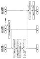
図7の例で、ユーザがスレーブ装置A(情報処理装置2)を操作し、当該操作に応じた機能プログラムを別のスレーブ装置B(情報処理装置3)が実行する場合につき、図8に以上の分散処理の例を示す。 In the example of FIG. 7, the case where the user operates the slave device A (information processing device 2) and another slave device B (information processing device 3) executes a function program corresponding to the operation will be described with reference to FIG. An example of distributed processing is shown.
図8の例では、ユーザがスレーブ装置Aを操作することによって、スレーブ装置Aを含むネットワークシステム全体の分散処理が開始して、まず、スレーブ装置Aは、ステップ81で、その操作情報をマスター装置1に送信する。
In the example of FIG. 8, when the user operates the slave device A, distributed processing of the entire network system including the slave device A starts. First, in
マスター装置1は、ステップ72で、その操作情報を受信し、さらにステップ73に進んで、自装置のメインメモリ26−1に記録されている自装置および他装置の装置情報テーブルから、各情報処理装置の動作状態などを調べて、受信した操作情報に応じた機能プログラムを実行することができる情報処理装置を選択する。この例は、スレーブ装置Bが選択される場合である。
In
次に、マスター装置1は、ステップ74で、その選択したスレーブ装置Bに対して機能プログラムの実行を要求する。
Next, in
スレーブ装置Bは、ステップ95で、その実行要求を受信し、さらにステップ96に進んで、実行要求された機能プログラムを実行する。
In
以上のように、ユーザは、1台の情報処理装置のみを操作することによって、他の情報処理装置を操作することなく、複数の情報処理装置1,2,3および4を仮想的な1台の情報処理装置7として動作させることができる。
As described above, by operating only one information processing apparatus, the user operates a plurality of
(2−6.各情報処理装置およびシステムの具体例:図9〜図12)
ネットワーク9を介して互いに接続される情報処理装置1,2,3および4は、基本的に上記のような情報処理コントローラ11,12,13および14によって情報処理を行うものであれば、どのようなものでもよいが、図9に、その一例を示す。
(2-6. Specific examples of information processing apparatuses and systems: FIGS. 9 to 12)
The
この例では、情報処理コントローラ11を備える情報処理装置1は、ハードディスクレコーダで、図10に示すように、ハードウェア構成としては、図1に示した外部記録部28−1として、ハードディスクを内蔵し、図1に示した外部記録部28−2として、DVD±R/RW,CD±R/RW,Blu−rayDisc(登録商標)などの光ディスクを装着できるとともに、情報処理コントローラ11のバス29−1に接続されたバス31−1に、放送受信部32−1、映像入力部33−1、音声入力部34−1、映像出力部35−1、音声出力部36−1、操作パネル部37−1、リモコン(遠隔操作)受光部38−1、ネットワーク接続部39−1および液晶表示部41−1が接続されたものである。
In this example, the
放送受信部32−1、映像入力部33−1および音声入力部34−1は、放送信号を受信し、または情報処理装置1の外部から映像信号および音声信号を入力し、それぞれ所定フォーマットのデジタルデータに変換して、情報処理コントローラ11での処理のためにバス31−1に送出するものであり、映像出力部35−1および音声出力部36−1は、情報処理コントローラ11からバス31−1に送出された映像データおよび音声データを処理して、デジタルデータのまま、またはアナログ信号に変換して、情報処理装置1の外部に送出するものであり、リモコン受光部38−1は、リモコン送信器43−1からのリモコン赤外線信号を受信するものである。
The broadcast receiving unit 32-1, the video input unit 33-1 and the audio input unit 34-1 receive a broadcast signal or input a video signal and an audio signal from the outside of the
図9の例の、情報処理コントローラ12を備える情報処理装置2も、ハードディスクレコーダで、図10において括弧内に参照番号を付して示すように、情報処理装置1と同様に構成されたものである。
The
それぞれハードディスクレコーダである情報処理装置1および2のソフトウェア構成としては、制御プログラムとして、図6に示したように、MSマネージャおよび能力交換プログラムを備え、機能プログラムとして、映像音声記録、映像音声再生、素材検索、番組録画予約などのためのプログラムを備え、デバイスドライバとして、放送受信、映像入力、音声入力、映像出力、音声出力、外部記録部入出力、ネットワーク入出力などのためのプログラムを備える。
As software configurations of the
図9の例の、情報処理コントローラ13を備える情報処理装置3は、PDA(Personal Digital Assistants)で、図11に示すように、ハードウェア構成としては、図1に示した外部記録部28−5として、メモリカードディスクを装着できるとともに、情報処理コントローラ13のバス29−3に接続されたバス51に、液晶表示部52、音声出力部53、カメラ部54、音声入力部55、キーボード部56およびネットワーク接続部57が接続されたものである。
The
なお、図1では内部を省略した情報処理コントローラ13は、メインプロセッサ21−3、サブプロセッサ23−7,23−8および23−9、DMAC(ダイレクトメモリアクセスコントローラ)25−3、DC(ディスクコントローラ)27−3、およびバス29−3を備え、そのメインプロセッサ21−3は、LS(ローカルストレージ)22−3を有し、各サブプロセッサ23−7,23−8および23−9は、LS(ローカルストレージ)24−7,24−8および24−9を有する。
1, the
PDAである情報処理装置3のソフトウェア構成としては、制御プログラムとして、図6に示したように、MSマネージャおよび能力交換プログラムを備え、機能プログラムとして、映像音声記録、映像音声再生、電話帳、ワープロ、表計算などのためのプログラム、およびWebブラウザを備え、デバイスドライバとして、映像出力、音声出力、カメラ映像入力、マイク音声入力、ネットワーク入出力などのためのプログラムを備える。
As shown in FIG. 6, the software configuration of the
図9の例の、情報処理コントローラ14を備える情報処理装置4は、ポータブルCDプレーヤで、図12に示すように、ハードウェア構成としては、図1に示した外部記録部28−6として、CD(Compact Disc)を装着できるとともに、情報処理コントローラ14のバス29−4に接続されたバス61に、液晶表示部62、音声出力部63、操作ボタン部64およびネットワーク接続部65が接続されたものである。
The
なお、図1では内部を省略した情報処理コントローラ14は、メインプロセッサ21−4、サブプロセッサ23−10,23−11および23−12、DMAC(ダイレクトメモリアクセスコントローラ)25−4、DC(ディスクコントローラ)27−4、およびバス29−4を備え、そのメインプロセッサ21−4は、LS(ローカルストレージ)22−4を有し、各サブプロセッサ23−10,23−11および23−12は、LS(ローカルストレージ)24−10,24−11および24−12を有する。
1, the
ポータブルCDプレーヤである情報処理装置4のソフトウェア構成としては、制御プログラムとして、図6に示したように、MSマネージャおよび能力交換プログラムを備え、機能プログラムとして、音楽再生などのためのプログラムを備え、デバイスドライバとして、音声出力、CD制御、ネットワーク入出力などのためのプログラムを備える。
As a software configuration of the
以上のような図9の例のネットワークシステムにおいて、情報処理装置1,3および4がネットワーク9に接続され、情報処理装置1がマスター装置(MSステータス=0)に設定され、情報処理装置3および4がスレーブ装置(MSステータス=1)に設定されているものとする。
In the network system of the example of FIG. 9 as described above, the
この状態で、新たに情報処理装置2がネットワーク9に接続されると、上述した方法によって、情報処理装置2内の情報処理コントローラ12に含まれるメインプロセッサ21−2で実行されるMSマネージャは、他の情報処理装置1,3および4にMSステータスを照会して、情報処理装置1が既にマスター装置として存在することを認識し、自装置(情報処理装置2)をスレーブ装置(MSステータス=1)に設定する。また、マスター装置に設定されている情報処理装置1は、新たに追加された情報処理装置2を含む各情報処理装置の装置情報を収集して、メインメモリ26−1内の装置情報テーブルを更新する。
In this state, when the
このような状態で、ユーザによってスレーブ装置である情報処理装置(PDA)3で2時間の放送番組の録画予約の操作が行われた場合を示す。 In this state, a case where a user performs an operation for recording reservation of a broadcast program for 2 hours in the information processing apparatus (PDA) 3 as a slave apparatus is shown.
この場合、スレーブ装置である情報処理装置3は、ユーザから録画開始時刻、録画終了時刻、録画対象放送チャネル、録画品質などの情報を含む録画予約情報の入力を受け付け、当該録画予約情報およびDMAコマンドとしての録画予約コマンドを含むソフトウェアセルを生成して、マスター装置である情報処理装置(ハードディスクレコーダ)1に送信する。
In this case, the
DMAコマンドが録画予約コマンドであるソフトウェアセルを受信した情報処理装置1内の情報処理コントローラ11に含まれるメインプロセッサ21−1は、録画予約コマンドを読み出すとともに、メインメモリ26−1内の装置情報テーブルを参照して、当該録画予約コマンドを実行可能な情報処理装置を特定する。
The main processor 21-1 included in the
まず、メインプロセッサ21−1は、装置情報テーブルに含まれる各情報処理装置1,2,3および4の情報処理装置種別IDを読み出して、録画予約コマンドに対応する機能プログラムを実行可能な情報処理装置を抽出する。ここでは、録画機能を示す情報処理装置種別IDを有する情報処理装置1および2が候補装置として特定され、情報処理装置3および4は候補装置から除外される。
First, the main processor 21-1 reads information processing device type IDs of the
次に、マスター装置である情報処理装置1内の情報処理コントローラ11に含まれるメインプロセッサ21−1は、装置情報テーブルを参照して、情報処理装置1および2のメインプロセッサまたはサブプロセッサの処理能力、メインメモリに関する情報などの、装置に関する情報を読み出し、情報処理装置1および2が録画予約コマンドに対応する機能プログラムの実行に必要な要求スペックを満足するか否かを判断する。ここでは、情報処理装置1および2が、ともに録画予約コマンドに対応する機能プログラムの実行に必要な要求スペックを満足するものとする。
Next, the main processor 21-1 included in the
さらに、メインプロセッサ21−1は、装置情報テーブルを参照して、情報処理装置1および2の外部記録部に関する情報を読み出し、外部記録部の空き容量が当該録画予約コマンドの実行に必要な容量を満足するか否かを判断する。情報処理装置1および2はハードディスクレコーダであるので、それぞれハードディスク28−1および28−3の、総容量と使用量との差分が、それぞれの空き容量に相当する。
Further, the main processor 21-1 refers to the device information table, reads information related to the external recording units of the
この場合、情報処理装置1のハードディスク28−1の空き容量が、録画時間に換算して10分であり、情報処理装置2のハードディスク28−3の空き容量が、録画時間に換算して20時間であるとする。
In this case, the free capacity of the hard disk 28-1 of the
このとき、マスター装置である情報処理装置1内の情報処理コントローラ11に含まれるメインプロセッサ21−1は、当該録画予約コマンドの実行に必要な2時間分の空き容量を確保できる情報処理装置を、実行要求先スレーブ装置として特定する。
At this time, the main processor 21-1 included in the
その結果、情報処理装置2のみが実行要求先スレーブ装置として選択され、マスター装置である情報処理装置1内の情報処理コントローラ11に含まれるメインプロセッサ21−1は、ユーザにより操作された情報処理装置3から送信された録画予約情報を含む当該録画予約コマンドを情報処理装置2に送信して、上記2時間の放送番組の録画予約の実行を要求する。
As a result, only the
情報処理装置2内の情報処理コントローラ12に含まれるメインプロセッサ21−2は、当該録画予約コマンドを解析して、録画に必要な機能プログラムを外部記録部であるハードディスク28−3からメインメモリ26−2にロードし、録画予約情報に従って録画を実行する。その結果、録画予約された2時間の放送番組の映像音声データが情報処理装置2のハードディスク28−3に記録される。
The main processor 21-2 included in the
このように、図9〜図12の例のネットワークシステムにおいても、ユーザは、1台の情報処理装置のみを操作することによって、他の情報処理装置を操作することなく、複数の情報処理装置1,2,3および4を仮想的な1台の情報処理装置7として動作させることができる。
As described above, also in the network systems of the examples of FIGS. 9 to 12, the user operates only one information processing apparatus, and operates a plurality of
〔3.各情報処理装置の処理能力の呈示(表示):図13〜図18〕
さらに、この発明では、上述したようなネットワークシステムにおいて、以下に示すように、ユーザが、その時々の各情報処理装置の処理能力を直感的かつ的確に把握できるようにする。
[3. Presentation (display) of processing capability of each information processing apparatus: FIGS. 13 to 18]
Further, according to the present invention, in the network system as described above, the user can intuitively and accurately grasp the processing capability of each information processing apparatus at that time, as described below.
(3−1.システム構成およびソフトウェア構成:図13および図14)
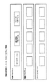
図13に、4台の情報処理装置1,2,3および4がネットワーク9に接続されている状態を示す。
(3-1. System Configuration and Software Configuration: FIGS. 13 and 14)
FIG. 13 shows a state where four
例えば、情報処理装置1および2は、図10に示したようなハードディスクレコーダであり、情報処理装置3は、図11に示したようなPDAであり、情報処理装置4は、図12に示したようなポータブルCDプレーヤであり、情報処理装置1がマスター装置として動作し、情報処理装置2,3および4がスレーブ装置A,BおよびCとして動作しているものとする。
For example, the
後述の処理能力呈示チャートは、ハードディスクレコーダである情報処理装置1および2については、図10に示した液晶表示部41−1および41−2、または映像出力部35−1および35−2に接続された映像表示装置に表示され、PDAである情報処理装置3については、図11に示した液晶表示部52に表示され、ポータブルCDプレーヤである情報処理装置4については、図12に示した液晶表示部62に表示される。
The processing capability presentation chart described later is connected to the liquid crystal display units 41-1 and 41-2 or the video output units 35-1 and 35-2 shown in FIG. The
各情報処理装置1,2,3および4は、同期して時刻を計測するように制御される。ただし、その時刻同期は、大まかな同期でよく、NTP(Network Time Protocol)のような既存のプロトコルによるものでよい。
Each of the
情報処理装置1,2,3および4のソフトウェア構成としては、図14に示すように、制御プログラムとして、図6に示したMSマネージャおよび能力交換プログラムのほかにリソースマネージャを用意し、機能プログラムおよびデバイスドライブとして、上述したように各情報処理装置に応じたものを用意する。
As the software configuration of the
リソースマネージャは、MSマネージャによるMSステータス(マスター装置では0、スレーブ装置では1)の設定後の、能力交換プログラムによる能力交換(マスター装置およびスレーブ装置における自装置および他装置の装置情報の取得)後、起動され、ネットワークに接続されている各情報処理装置の、そのときの処理能力を呈示するために、以下のような処理を行うものである。 After the MS manager sets the MS status (0 for the master device and 1 for the slave device), after the resource exchange by the capability exchange program (acquisition of device information of the own device and other devices in the master device and slave device) In order to present the processing capability of each information processing apparatus that is activated and connected to the network, the following processing is performed.
(3−2.処理能力の呈示のための処理:図15および図16)
図15に、情報処理装置1,2,3および4のリソースマネージャによって実行される処理能力呈示処理の一例を示す。
(3-2. Processing for Presenting Processing Capacity: FIGS. 15 and 16)
FIG. 15 shows an example of the processing capability presentation process executed by the resource manager of the
この例は、図13のように情報処理装置1,2,3および4がネットワーク9に接続され、MSマネージャによって、情報処理装置1がマスター装置に設定され、情報処理装置2,3および4がスレーブ装置A,BおよびCに設定され、能力交換プログラムによって、各情報処理装置1,2,3および4が上述したように自装置および他装置の装置情報を取得した状態で、ユーザが、スレーブ装置Aとして動作している情報処理装置2に対して、各情報処理装置の処理能力の呈示を指示した場合である。
In this example, as shown in FIG. 13, the
このユーザの指示によって、まず、情報処理装置2のリソースマネージャは、ステップ121で、他の各情報処理装置、すなわち情報処理装置1,3および4に、詳細ステータス要求コマンドを送信し、これを受けて、他の各情報処理装置、すなわち情報処理装置1,3および4のリソースマネージャは、ステップ111,131および141で、それぞれ情報処理装置2に詳細ステータス返信コマンドを送信する。
In response to this user instruction, first, the resource manager of the
この場合の詳細ステータス要求コマンドは、図3に示して上述したステータス要求コマンドと同様のものであり、詳細ステータス返信コマンドは、図16に示されるものである。 The detailed status request command in this case is the same as the status request command shown in FIG. 3 and described above, and the detailed status reply command is shown in FIG.
次に、情報処理装置2のリソースマネージャは、ステップ122で、情報処理装置1,3および4から送信された詳細ステータス返信コマンドを受信して、後述のように、自装置を含む各情報処理装置、すなわち情報処理装置1,2,3および4についてのネットワークレイテンシーを計算し、さらにステップ123に進んで、後述のような処理能力呈示チャートを表示するためのデータを生成し、さらにステップ124に進んで、その表示用データによって、情報処理装置2の図10に示した液晶表示部41−2、または映像出力部35−2に接続された映像表示装置の表示画面上に、処理能力呈示チャートを表示する。
Next, the resource manager of the
上記の例で、詳細ステータス要求コマンドによって、情報処理装置2から詳細ステータス情報の送信を要求された情報処理装置1,3および4は、それぞれ詳細ステータス返信コマンドによって、自装置についての図16に示すような詳細ステータス情報を情報処理装置2に返信する。
In the above example, the
ただし、図16の詳細ステータス情報中の詳細ステータス要求コマンド送信時刻および詳細ステータス返信コマンド受信時刻は、詳細ステータス情報の送信を要求した情報処理装置2が付加するもので、情報処理装置1,3および4が返信するのは、情報処理装置ID以下の各情報である。
However, the detailed status request command transmission time and the detailed status reply command reception time in the detailed status information of FIG. 16 are added by the
また、情報処理装置2のリソースマネージャは、ステップ121または122で、自装置についての詳細ステータス情報として、同様に図16の情報処理装置ID以下の各情報を収集する。
Further, in step 121 or 122, the resource manager of the
この詳細ステータス情報は、情報処理装置ID、情報処理装置種別IDおよびMSステータスを除くと、メインプロセッサに関する情報、サブプロセッサに関する情報、メインメモリに関する情報、および外部記録部に関する情報に分けられる。 Excluding the information processing device ID, the information processing device type ID, and the MS status, the detailed status information is divided into information about the main processor, information about the sub processor, information about the main memory, and information about the external recording unit.
メインプロセッサに関する情報は、各情報処理装置のメインプロセッサ21についての、メインプロセッサ動作周波数、メインプロセッサステータス、メインプロセッサ使用率、機能プログラムID、および機能プログラム優先度である。
Information on the main processor is the main processor operating frequency, main processor status, main processor usage rate, function program ID, and function program priority for the
メインプロセッサ動作周波数は、これが高いほど、当該情報処理装置の処理能力が高い。 The higher the main processor operating frequency, the higher the processing capability of the information processing apparatus.
メインプロセッサステータスは、上述していないが、当該メインプロセッサが現に機能プログラムを実行しているか否かを表し、例えば、機能プログラム実行中であるときには1とされ、機能プログラムを実行していないときには0とされる。 Although not described above, the main processor status represents whether or not the main processor is currently executing a function program. For example, the main processor status is 1 when the function program is being executed, and 0 when the function program is not being executed. It is said.
メインプロセッサ使用率は、上述したように当該メインプロセッサの全処理能力に対する使用中の処理能力の比率を表し、これが低いほど、当該メインプロセッサの余剰能力が高く、当該情報処理装置のそのときの処理能力が高い。 As described above, the main processor usage rate represents the ratio of the processing capacity in use to the total processing capacity of the main processor, and the lower this is, the higher the surplus capacity of the main processor is. High ability.
機能プログラムIDは、当該メインプロセッサで実行中の機能プログラムを識別する識別子であり、機能プログラム優先度は、その機能プログラムの優先度であり、例えば、high(優先度が高い)およびlow(優先度が低い)の2段階に区分される。 The function program ID is an identifier for identifying the function program being executed by the main processor, and the function program priority is the priority of the function program. For example, high (high priority) and low (priority) Is low).
メインプロセッサに関する当該情報処理装置のそのときの処理能力は、メインプロセッサ動作周波数とメインプロセッサ使用率とによって決まり、メインプロセッサ動作周波数が高く、メインプロセッサ使用率が低いほど、当該情報処理装置のそのときの処理能力が高い。 The processing capacity of the information processing apparatus for the main processor at that time is determined by the main processor operating frequency and the main processor usage rate, and the higher the main processor operating frequency and the lower the main processor usage rate, the higher the processing speed of the information processing apparatus. High processing capacity.
ただし、メインプロセッサに関する当該情報処理装置のそのときの処理能力については、メインプロセッサ使用率として、優先度の低い機能プログラムを実行している場合を除外し、優先度の高い機能プログラムを実行している場合のみを考慮して、処理能力を算出するようにしてもよい。 However, regarding the processing capacity at that time of the information processing apparatus related to the main processor, as a main processor usage rate, a case where a function program with a low priority is executed is excluded, and a function program with a high priority is executed. The processing capability may be calculated in consideration of only the case where there is.
サブプロセッサに関する情報は、サブプロセッサ数、サブプロセッサID、サブプロセッサステータス、サブプロセッサ使用率、機能プログラムID、機能プログラム優先度、およびサブプロセッサプログラムIDである。 The information regarding the sub processor is the number of sub processors, sub processor ID, sub processor status, sub processor usage rate, function program ID, function program priority, and sub processor program ID.
サブプロセッサ数は、当該情報処理装置が備えるサブプロセッサ23の数を表し、個々のサブプロセッサ23が有する処理能力が同じであるとすると、サブプロセッサ数が多いほど、当該情報処理装置の処理能力が高い。
The number of sub-processors represents the number of
サブプロセッサID、サブプロセッサステータスおよびサブプロセッサ使用率は、上述したように個々のサブプロセッサ23ごとに設定または算出される。機能プログラムIDおよび機能プログラム優先度は、当該サブプロセッサで実行中または当該サブプロセッサに実行予約中のサブプロセッサプログラムと連携動作する機能プログラムの識別子および優先度である。サブプロセッサプログラムIDは、当該サブプロセッサで実行中または当該サブプロセッサに実行予約中のサブプロセッサプログラムを識別する識別子である。
The sub processor ID, sub processor status, and sub processor usage rate are set or calculated for each
サブプロセッサに関する当該情報処理装置のそのときの処理能力は、当該情報処理装置のサブプロセッサ数と、その各サブプロセッサの使用率の平均値とによって決まり、サブプロセッサ数が多く、各サブプロセッサの使用率の平均値が低いほど、当該情報処理装置のそのときの処理能力が高い。 The processing capacity of the information processing apparatus related to the sub processor at that time is determined by the number of sub processors of the information processing apparatus and the average value of the usage rate of each of the sub processors. The lower the average value of the rate, the higher the processing capability of the information processing apparatus at that time.
例えば、ある情報処理装置が3個のサブプロセッサを備え、第1サブプロセッサの使用率が30%、第2サブプロセッサの使用率が40%、第3サブプロセッサの使用率が50%であるとき、各サブプロセッサの使用率の平均値は40%である。 For example, when an information processing apparatus includes three sub processors, the usage rate of the first sub processor is 30%, the usage rate of the second sub processor is 40%, and the usage rate of the third sub processor is 50%. The average usage rate of each sub processor is 40%.
ただし、サブプロセッサに関する当該情報処理装置のそのときの処理能力についても、サブプロセッサ使用率として、優先度の低い機能プログラムと連携動作するサブプロセッサプログラムの実行中または実行予約中である場合を除外し、優先度の高い機能プログラムと連携動作するサブプロセッサプログラムの実行中または実行予約中である場合のみを考慮して、処理能力を算出するようにしてもよい。 However, the processing capability of the information processing apparatus related to the sub processor also excludes the case where the sub processor usage rate is executing or reserved for execution of the sub processor program operating in cooperation with the function program having a low priority. The processing capability may be calculated in consideration only when the sub processor program operating in cooperation with the high priority function program is being executed or reserved for execution.
メインメモリに関する情報は、メインメモリ総容量およびメインメモリ使用量であり、メインメモリに関する当該情報処理装置のそのときの処理能力は、メインメモリ26の空き容量(総容量から使用量を減じた容量)によって決まり、メインメモリ空き容量が大きいほど、当該情報処理装置のそのときの処理能力が高い。 The information related to the main memory is the total capacity of the main memory and the amount of main memory used, and the processing capacity of the information processing apparatus related to the main memory at that time is the free capacity of the main memory 26 (the capacity obtained by subtracting the usage from the total capacity). As the main memory free capacity is larger, the processing capacity of the information processing apparatus at that time is higher.
外部記録部に関する情報は、外部記録部数、外部記録部ID、外部記録部種別ID、外部記録部総容量、および外部記録部使用量である。上述したように、外部記録部ID、外部記録部種別ID、外部記録部総容量および外部記録部使用量は、当該情報処理装置に接続されている個々の外部記録部28ごとに設定または算出される。 The information related to the external recording unit is the number of external recording units, the external recording unit ID, the external recording unit type ID, the external recording unit total capacity, and the external recording unit usage. As described above, the external recording unit ID, the external recording unit type ID, the external recording unit total capacity, and the external recording unit usage amount are set or calculated for each external recording unit 28 connected to the information processing apparatus. The
外部記録部に関する当該情報処理装置のそのときの処理能力は、当該情報処理装置に接続されている各外部記録部の空き容量(総容量から使用量を減じた容量)の和によって決まり、その和が大きいほど、当該情報処理装置のそのときの処理能力が高い。 The current processing capacity of the information processing apparatus related to the external recording unit is determined by the sum of the free capacity (capacity obtained by subtracting the usage amount from the total capacity) of each external recording unit connected to the information processing apparatus. Is larger, the processing capability of the information processing apparatus at that time is higher.
さらに、上記の例で、情報処理装置2のリソースマネージャは、ステップ122で、自装置を含む各情報処理装置についてのネットワークレイテンシーを計算する。
Furthermore, in the above example, the resource manager of the
情報処理装置1,3,4についてのネットワークレイテンシーNL1,NL3,NL4は、それぞれ、図16の第1段目に示す情報処理装置1,3,4に詳細ステータス要求コマンドを送信した時刻と、図16の第2段目に示す情報処理装置1,3,4から詳細ステータス返信コマンドを受信した時刻との差の時間によって算出する。
The network latencies NL1, NL3, and NL4 for the
ネットワークレイテンシーの算出方法として、例えば、基準時刻差(例として10msecとする)を定義する。そして、情報処理装置2が情報処理装置1に詳細ステータス要求コマンドを送信した時刻と情報処理装置1から詳細ステータス返信コマンドを受信した時刻との時刻差が100msecである場合には、100msec÷10msec=10によって、NL1=10と算出される。同様に、情報処理装置3,4についてもネットワークレイテンシーNL3,NL4を算出する。情報処理装置2自身についてのネットワークレイテンシーNL2は、時刻差が発生しないため、NL2=0となる。
As a network latency calculation method, for example, a reference time difference (for example, 10 msec) is defined. When the time difference between the time when the
ネットワークレイテンシーは、その時間が短いほど、当該情報処理装置の処理能力が高い。 As the network latency is shorter, the processing capability of the information processing apparatus is higher.
以上のように獲得した詳細ステータス情報およびネットワークレイテンシーをもとに、情報処理装置2のリソースマネージャは、ステップ123で、処理能力呈示チャートの表示用データを生成し、ステップ124で、処理能力呈示チャートを表示する。
Based on the detailed status information and network latency acquired as described above, the resource manager of the
(3−3.呈示態様:図17および図18)
図17に、処理能力呈示チャートの一例を示す。
(3-3. Presentation Mode: FIGS. 17 and 18)
FIG. 17 shows an example of a processing capability presentation chart.
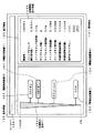
この例では、ユーザが操作した情報処理装置2の図10に示した液晶表示部41−2、または映像出力部35−2に接続された映像表示装置の表示画面151中の、左側の表示領域152に、各情報処理装置1,2,3および4のそのときの処理能力が1次元座標グラフとして表示される。
In this example, the left display area in the display screen 151 of the video display device connected to the liquid crystal display unit 41-2 shown in FIG. 10 of the
具体的に、表示領域152には、処理能力呈示バー155を表示する。処理能力呈示バー155は、例えば、下端の横幅がゼロで、上端側になるほど横幅が漸次大きくなるものとし、下端が処理能力0%、上端が処理能力100%を示すものとする。
Specifically, a processing
この場合の処理能力は、情報処理装置の、(1)メインプロセッサに関する処理能力、(2)サブプロセッサに関する処理能力、(3)メインメモリに関する処理能力、(4)外部記録部に関する処理能力、(5)ネットワークレイテンシーに関する処理能力、のいずれかとし、または、これら(1)〜(5)中の2つ以上を組み合わせたものとする。 In this case, the processing capability is (1) processing capability related to the main processor, (2) processing capability related to the sub processor, (3) processing capability related to the main memory, (4) processing capability related to the external recording unit, ( 5) Any one of the processing capabilities relating to network latency, or a combination of two or more of (1) to (5).
処理能力100%は、例えば、メインメモリに関する処理能力であれば、上記のメインメモリ空き容量が512MB(メガバイト)、などというように、あらかじめ最大値として設定された処理能力値を表すものである。
The
ネットワークレイテンシーに関する処理能力は、100%から上記のネットワークレイテンシーNLの値を引いたものとする。すなわち、情報処理装置2については、NL2=0であるので、情報処理装置2のネットワークレイテンシーに関する処理能力は100%である。同様に、NL1=10から、情報処理装置1のネットワークレイテンシーに関する処理能力は90%である。情報処理装置3,4のネットワークレイテンシーに関する処理能力も、同様にNL3,NL4から算出される。
The processing capability regarding the network latency is assumed to be 100% minus the value of the network latency NL. That is, for the
表示される処理能力呈示バー155が、上記(1)〜(5)中のいずれを示しているかをユーザに呈示するようにしてもよい。例えば、処理能力呈示バー155が(1)メインプロセッサに関する処理能力を示しているときには、表示領域152内に「メインプロセッサに関する処理能力」と表示し、処理能力呈示バー155が(3)メインメモリに関する処理能力と(4)外部記録部に関する処理能力の組み合わせを示しているときには、表示領域152内に「メインメモリに関する処理能力」と「外部記録部に関する処理能力」を表示する。さらに、処理能力呈示バー155が示す処理能力を、ユーザの操作によって切り替えることができるようにしてもよい。
The displayed processing
上記(1)〜(5)中の2つ以上を組み合わせる場合には、あらかじめ定められた関数式によって、総合的な処理能力値を表す。さらに、その関数式は、固定されている場合に限らず、情報処理装置に実行させようとする機能に応じて、関数式の係数や次数などを切り替えるようにしてもよい。 When two or more of the above (1) to (5) are combined, a comprehensive processing capability value is represented by a predetermined function expression. Furthermore, the function formula is not limited to a fixed one, and the function formula coefficient and order may be switched in accordance with the function to be executed by the information processing apparatus.
そして、各情報処理装置1,2,3および4のそのときの処理能力を、同様に上記(1)〜(5)中の1つまたは複数から算出し、それぞれ情報処理装置1,2,3および4を示すアイコンや記号などの標章161,162,163および164を、処理能力呈示バー155上の、算出結果の処理能力値(座標値)の位置に表示する。
And the processing capacity at that time of each
図17の例では、ハードディスクレコーダである情報処理装置1のそのときの処理能力値が70%であるので、情報処理装置1を示す標章161が処理能力呈示バー155上の70%の座標値の位置に表示され、ハードディスクレコーダである情報処理装置2のそのときの処理能力値が84%であるので、情報処理装置2を示す標章162が処理能力呈示バー155上の84%の座標値の位置に表示され、PDAである情報処理装置3のそのときの処理能力値が43%であるので、情報処理装置3を示す標章163が処理能力呈示バー155上の43%の座標値の位置に表示され、ポータブルCDプレーヤである情報処理装置4のそのときの処理能力値が9%であるので、情報処理装置4を示す標章164が処理能力呈示バー155上の9%の座標値の位置に表示される。
In the example of FIG. 17, the processing capability value at that time of the
したがって、ユーザは、そのときの各情報処理装置1,2,3および4の処理能力を直感的かつ的確に把握することができ、情報処理装置1,2,3または4に処理を実行させた場合のターンアラウンドタイムを予測することができる。
Therefore, the user can intuitively and accurately grasp the processing ability of each
さらに、この例では、ユーザが、標章161,162,163および164のいずれかをクリックするなど、操作することによって、表示画面151中の右側の表示領域153に、詳細情報呈示画面156が表示され、操作された標章で示される情報処理装置に関する詳細な情報が呈示される。図17の例は、ユーザが標章161を操作したことによって、ハードディスクレコーダである情報処理装置1に関する詳細な情報が呈示された場合である。
Further, in this example, when the user clicks one of the
したがって、ユーザは、表示領域152に表示された1次元座標グラフと、表示領域153に表示された詳細情報とによって、そのときの各情報処理装置1,2,3および4の処理能力を直感的かつ詳細に把握することができる。
Therefore, the user can intuitively determine the processing capability of each
さらに、この例では、表示画面151の上部にツールバー154が表示され、ユーザがこのツールバー154を操作することによって、表示画面151に操作画面が表示され、その操作画面での操作によって、ユーザは、各情報処理装置の処理能力を見て自身が選択した情報処理装置に、上述した放送番組の録画などの処理を実行させることができる。
Furthermore, in this example, a
例えば、ユーザが情報処理装置2を選択して放送番組の録画予約の操作を行った場合には、図7および図9の例で上述したように、その操作情報が情報処理装置2からマスター装置として動作している情報処理装置1に送信され、情報処理装置1内の情報処理コントローラ11に含まれるメインプロセッサ21−1は、当該の操作に応じた機能プログラムの実行要求先の情報処理装置として、ユーザが指示した情報処理装置2を選択し、情報処理装置2に当該の操作に応じた機能プログラムを実行させる。
For example, when the user selects the
この場合、上述したように、メインプロセッサに関する、またはサブプロセッサに関する各情報処理装置のそのときの処理能力につき、メインプロセッサ使用率、またはサブプロセッサ使用率として、優先度の低い機能プログラムを実行している場合、または優先度の低い機能プログラムと連携動作するサブプロセッサプログラムの実行中または実行予約中である場合を除外し、優先度の高い機能プログラムを実行している場合、または優先度の高い機能プログラムと連携動作するサブプロセッサプログラムの実行中または実行予約中である場合のみを考慮して、処理能力を算出し、図17の例のように表示することによって、ユーザは、優先度の高い処理を新たに実行させる場合、そのときの処理能力として、当該の処理を優先的に実行できる処理能力を有する情報処理装置が、いずれの情報処理装置であるかを容易に知ることができる。 In this case, as described above, a function program having a low priority is executed as the main processor usage rate or the sub processor usage rate for the processing capacity at that time of each information processing device relating to the main processor or sub processor. Or when a sub-processor program that operates in cooperation with a low-priority functional program is being executed or reserved for execution, and a high-priority functional program is being executed or a high-priority function The processing capability is calculated only in consideration of the case where the sub processor program operating in cooperation with the program is being executed or reserved for execution, and the user can perform processing with high priority by displaying as shown in the example of FIG. As a processing capability at that time, the relevant processing can be executed preferentially. The information processing apparatus having that processing power, it is possible to know which of the information processing apparatus easily.
図18に、処理能力呈示チャートの他の例を示す。この例では、ユーザが操作した情報処理装置2の図10に示した液晶表示部41−2、または映像出力部35−2に接続された映像表示装置の表示画面151に、各情報処理装置1,2,3および4のそのときの処理能力が2次元座標グラフとして表示される。
FIG. 18 shows another example of the processing capability presentation chart. In this example, each
具体的に、その2次元座標は、上記(5)のネットワークレイテンシーに関する処理能力を、縦軸に示し、上記(1)〜(4)の、メインプロセッサに関する処理能力、サブプロセッサに関する処理能力、メインメモリに関する処理能力、および外部記録部に関する処理能力を、定められた関数式によって総合的に表したものを、横軸に示したものである。 Specifically, the two-dimensional coordinates indicate the processing capability relating to the network latency of (5) above on the vertical axis, and the processing capability relating to the main processor, the processing capability relating to the sub processor, and the main capability of (1) to (4) above. The horizontal axis represents the processing capability related to the memory and the processing capability related to the external recording unit, which are comprehensively expressed by a predetermined function expression.
ネットワークレイテンシーが小さい(短い)ほど、ネットワークレイテンシーに関する処理能力が高いので、縦軸のプラス方向はネットワークレイテンシーが小さい方向、マイナス方向はネットワークレイテンシーが大きい方向とし、その他に関する処理能力については、横軸のプラス方向を処理能力が高い(負荷が小さい)方向、マイナス方向を処理能力が低い(負荷が大きい)方向とする。 The smaller (shorter) the network latency, the higher the processing capacity related to network latency, so the positive direction on the vertical axis is the direction where the network latency is small, the negative direction is the direction where the network latency is large, and the processing capacity related to others is The plus direction is the direction with high processing capability (small load), and the minus direction is the direction with low processing capability (large load).
しかも、2次元座標の原点位置は、マスター装置として動作している情報処理装置1のそのときの、ネットワークレイテンシーの値およびその他に関する処理能力の値を示す座標位置とし、その原点位置に、情報処理装置1を示す標章161を表示し、スレーブ装置として動作している他の情報処理装置2,3および4を示す標章162,163および164を、それぞれ情報処理装置2,3および4のそのときの、ネットワークレイテンシーの値およびその他に関する処理能力の値を示す座標位置に表示する。
Moreover, the origin position of the two-dimensional coordinates is the coordinate position indicating the network latency value and other processing capability values at that time of the
したがって、ユーザは、そのときの各情報処理装置1,2,3および4の処理能力を直感的かつ的確に把握することができる。
Therefore, the user can intuitively and accurately grasp the processing capabilities of the
2次元座標の原点位置は、ユーザが操作している情報処理装置のそのときの、ネットワークレイテンシーの値およびその他に関する処理能力の値を示す座標位置としてもよい。 The origin position of the two-dimensional coordinate may be a coordinate position indicating the value of the network latency and the value of the processing capability relating to others of the information processing apparatus operated by the user at that time.
さらに、この例でも、表示画面151の上部にツールバー154が表示され、ユーザがこのツールバー154を操作することによって、表示画面151に操作画面が表示され、その操作画面での操作によって、ユーザは、各情報処理装置の処理能力を見て自身が選択した情報処理装置に、上述した放送番組の録画などの処理を実行させることができるように、システムを構成する。
Furthermore, also in this example, a
図18の例は、2次元座標グラフによって、ネットワークレイテンシーに関する処理能力と、その他に関する処理能力とを表示する場合であるが、2次元座標グラフによって、(a)メインプロセッサに関する処理能力(余剰能力)と、サブプロセッサに関する処理能力(余剰能力)、(b)メインプロセッサまたはサブプロセッサに関する処理能力(余剰能力)と、メインメモリに関する処理能力(空き容量)、(c)ネットワークレイテンシーに関する処理能力と、メインプロセッサまたはサブプロセッサに関する処理能力(余剰能力)、(d)ネットワークレイテンシーに関する処理能力と、メインメモリに関する処理能力(空き容量)、などを表示するようにしてもよい。 The example of FIG. 18 is a case where the processing capability relating to network latency and the processing capability relating to others are displayed by a two-dimensional coordinate graph. However, (a) the processing capability relating to the main processor (surplus capability) is displayed by the two-dimensional coordinate graph. Processing capacity (surplus capacity) related to the sub processor, (b) processing capacity related to the main processor or the sub processor (surplus capacity), processing capacity related to the main memory (free capacity), (c) processing capacity related to network latency, You may make it display the processing capacity (surplus capacity) regarding a processor or a sub processor, (d) the processing capacity regarding network latency, the processing capacity (free capacity) regarding a main memory, and the like.
また、図では省略するが、3次元座標グラフによって、それぞれの情報処理装置のそのときの3種の処理能力を表示するようにしてもよい。 Although not shown in the figure, the three types of processing capabilities of each information processing apparatus at that time may be displayed by a three-dimensional coordinate graph.
主要部については図中に全て記述したので、ここでは省略する。 Since all the main parts are described in the figure, they are omitted here.
Claims (8)
プログラムを実行するプロセッサ手段と、
プログラムおよびデータが展開されるメモリ手段と、
当該情報処理装置、および前記ネットワークを介して当該情報処理装置と接続された、プロセッサ手段およびメモリ手段を備える他の情報処理装置の、そのときの処理能力を示す情報を収集し、そのときの処理能力をチャートとしてディスプレイ上に表示する管理手段と、
を備えることを特徴とする情報処理装置。 An information processing apparatus connected to a network,
Processor means for executing a program;
Memory means in which programs and data are expanded;
Collects information indicating the current processing capability of the information processing apparatus and another information processing apparatus including the processor means and the memory means connected to the information processing apparatus via the network, and processes at that time A management means for displaying the ability as a chart on the display;
An information processing apparatus comprising:
前記処理能力は、各情報処理装置の前記プロセッサ手段の余剰能力、各情報処理装置の前記メモリ手段の空き容量、各情報処理装置に接続された外部記録手段の空き容量、または各情報処理装置の通信レートであり、
前記チャートは、前記処理能力を1次元座標で示し、それぞれの情報処理装置を示す標章を、前記1次元座標上の、それぞれの情報処理装置の前記処理能力を示す座標値の位置に付加したものである情報処理装置。 The information processing apparatus according to claim 1,
The processing capacity is the surplus capacity of the processor means of each information processing apparatus, the free capacity of the memory means of each information processing apparatus, the free capacity of external recording means connected to each information processing apparatus, or the capacity of each information processing apparatus Communication rate,
The chart indicates the processing capability in one-dimensional coordinates, and a mark indicating each information processing device is added to the position of the coordinate value indicating the processing capability of each information processing device on the one-dimensional coordinate. An information processing device.
前記処理能力は、各情報処理装置の前記プロセッサ手段の余剰能力、各情報処理装置の前記メモリ手段の空き容量、各情報処理装置に接続された外部記録手段の空き容量、および各情報処理装置の通信レートのうちの、少なくとも2項目であり、
前記チャートは、前記処理能力を、その項目数に応じた2次元座標または3次元座標で示し、それぞれの情報処理装置を示す標章を、前記2次元座標上または前記3次元座標上の、それぞれの情報処理装置の前記処理能力を示す座標値の位置に付加したものである情報処理装置。 The information processing apparatus according to claim 1,
The processing capacity includes the surplus capacity of the processor means of each information processing apparatus, the free capacity of the memory means of each information processing apparatus, the free capacity of external recording means connected to each information processing apparatus, and the It is at least two items of the communication rate,
The chart indicates the processing capability in two-dimensional coordinates or three-dimensional coordinates according to the number of items, and marks indicating the respective information processing devices are respectively displayed on the two-dimensional coordinates or the three-dimensional coordinates. An information processing apparatus added to the position of a coordinate value indicating the processing capability of the information processing apparatus.
一の情報処理装置から他の各情報処理装置に、それぞれのそのときの処理能力を示す情報の送信を要求する第1工程と、
その要求に応答して、前記他の各情報処理装置が前記一の情報処理装置に、それぞれのそのときの処理能力を示す情報を返信する第2工程と、
その情報を受信して、前記一の情報処理装置が、自装置および前記他の各情報処理装置の、そのときの処理能力をチャートとしてディスプレイ上に表示する第3工程と、
を備えることを特徴とする処理能力呈示方法。 A plurality of information processing devices each including a processor means for executing a program and a memory means for developing the program and data present the processing capability of each information processing device in a network system connected on the same network. A method,
A first step of requesting each information processing device from one information processing device to transmit information indicating the processing capacity at that time;
In response to the request, a second step in which each of the other information processing devices returns information indicating the processing capability at that time to the one information processing device;
Receiving the information, and the one information processing apparatus displays the processing capability at that time of the own apparatus and each of the other information processing apparatuses as a chart on a display;
A processing capability presentation method characterized by comprising:
前記処理能力は、各情報処理装置の前記プロセッサ手段の余剰能力、各情報処理装置の前記メモリ手段の空き容量、各情報処理装置に接続された外部記録手段の空き容量、または各情報処理装置の通信レートとし、
前記チャートは、前記処理能力を1次元座標で示し、それぞれの情報処理装置を示す標章を、前記1次元座標上の、それぞれの情報処理装置の前記処理能力を示す座標値の位置に付加したものとする処理能力呈示方法。 In the processing capacity presentation method according to claim 5,
The processing capacity is the surplus capacity of the processor means of each information processing apparatus, the free capacity of the memory means of each information processing apparatus, the free capacity of external recording means connected to each information processing apparatus, or the capacity of each information processing apparatus Communication rate,
The chart indicates the processing capability in one-dimensional coordinates, and a mark indicating each information processing device is added to the position of the coordinate value indicating the processing capability of each information processing device on the one-dimensional coordinate. Processing capacity presentation method to be assumed.
前記処理能力は、各情報処理装置の前記プロセッサ手段の余剰能力、各情報処理装置の前記メモリ手段の空き容量、各情報処理装置に接続された外部記録手段の空き容量、および各情報処理装置の通信レートのうちの、少なくとも2項目とし、
前記チャートは、前記処理能力を、その項目数に応じた2次元座標または3次元座標で示し、それぞれの情報処理装置を示す標章を、前記2次元座標上または前記3次元座標上の、それぞれの情報処理装置の前記処理能力を示す座標値の位置に付加したものとする処理能力呈示方法。 In the processing capacity presentation method according to claim 5,
The processing capacity includes the surplus capacity of the processor means of each information processing apparatus, the free capacity of the memory means of each information processing apparatus, the free capacity of external recording means connected to each information processing apparatus, and the At least two items of communication rate,
The chart indicates the processing capability by two-dimensional coordinates or three-dimensional coordinates according to the number of items, and marks indicating the respective information processing devices are respectively displayed on the two-dimensional coordinates or the three-dimensional coordinates. The processing capability presentation method which shall be added to the position of the coordinate value which shows the said processing capability of this information processing apparatus.
一の情報処理装置から他の各情報処理装置に、それぞれのそのときの処理能力を示す情報の送信を要求する手段、
その要求に応答して、前記他の各情報処理装置が前記一の情報処理装置に、それぞれのそのときの処理能力を示す情報を返信する手段、および、
その情報を受信して、前記一の情報処理装置が、自装置および前記他の各情報処理装置の、そのときの処理能力をチャートとしてディスプレイ上に表示する手段、
として機能させるための処理能力呈示用プログラム。 A plurality of information processing devices each including a processor means for executing a program and a memory means for developing the program and data present the processing capability of each information processing device in a network system connected on the same network. For the computer,
Means for requesting transmission of information indicating the processing capacity of each information processing device from one information processing device to each of the other information processing devices;
In response to the request, each of the other information processing devices returns information indicating the current processing capability to the one information processing device, and
Means for receiving the information, and the one information processing device displays the processing capability at that time of its own device and each of the other information processing devices as a chart on a display;
Program for presenting processing capacity to function as
Priority Applications (1)
| Application Number | Priority Date | Filing Date | Title |
|---|---|---|---|
| JP2004110256A JP2005293418A (en) | 2004-04-02 | 2004-04-02 | Information processor, network system, throughput presentation method and program for throughput presentation |
Applications Claiming Priority (1)
| Application Number | Priority Date | Filing Date | Title |
|---|---|---|---|
| JP2004110256A JP2005293418A (en) | 2004-04-02 | 2004-04-02 | Information processor, network system, throughput presentation method and program for throughput presentation |
Publications (1)
| Publication Number | Publication Date |
|---|---|
| JP2005293418A true JP2005293418A (en) | 2005-10-20 |
Family
ID=35326250
Family Applications (1)
| Application Number | Title | Priority Date | Filing Date |
|---|---|---|---|
| JP2004110256A Pending JP2005293418A (en) | 2004-04-02 | 2004-04-02 | Information processor, network system, throughput presentation method and program for throughput presentation |
Country Status (1)
| Country | Link |
|---|---|
| JP (1) | JP2005293418A (en) |
-
2004
- 2004-04-02 JP JP2004110256A patent/JP2005293418A/en active Pending
Similar Documents
| Publication | Publication Date | Title |
|---|---|---|
| KR101089965B1 (en) | Network system, distributed processing method and information processing apparatus | |
| US8103771B2 (en) | Distributing processing apparatus, method, and system | |
| JP4599923B2 (en) | Information processing system, information processing method, and computer program | |
| KR20060043201A (en) | Information processing system, information processing method, and computer program | |
| TWI261464B (en) | Information processing system, information processing method, and computer program | |
| KR101119870B1 (en) | Information processing system and method | |
| KR101210114B1 (en) | Information processing system, information processing method, and computer readable recording medium having computer program recorded | |
| JP2014513494A (en) | Method and system for dynamically creating and servicing master-slave pairs within and between switch fabrics of portable computing devices | |
| US20050196145A1 (en) | Content reproduction apparatus, content recording apparatus, network system, and content recording/reproduction method | |
| TWI276969B (en) | Information processing apparatus, method, system and information processing program of accessible media | |
| JP2005276165A (en) | Information processor, network system state presentation method, and computer program | |
| JP2005339174A (en) | Information processing system, information processing method, and computer program therefor | |
| JP4349189B2 (en) | Network system, program recording reservation method, and information processing apparatus | |
| JP2005293418A (en) | Information processor, network system, throughput presentation method and program for throughput presentation | |
| US20050246595A1 (en) | Network system, information processing apparatus, master apparatus, and apparatus information display method | |
| JP2005251163A (en) | Information processing device, information processing method, information processing system and information processing program | |
| JP2005267150A (en) | Information processing system, information processing method, and computer program | |
| JP2005252901A (en) | Server device, remote control system, and remote control method | |
| KR20060071069A (en) | Information processing apparatus, information processing method, information processing system, and computer program for information processing | |
| JP2009025868A (en) | Communication interface module and program | |
| JP2007004241A (en) | Distributed processing system, computer resource management server, user terminal, distributed processing method and program for them | |
| JP2006025164A (en) | Information processor, network system, and remote operating method | |
| JP2006018343A (en) | Information processor, network system, and function expansion method for information processor | |
| JPS63195723A (en) | File managing device |