JP2004304834A - Method for inserting robust electronic watermark to signal and method for detecting electronic watermark - Google Patents
Method for inserting robust electronic watermark to signal and method for detecting electronic watermark Download PDFInfo
- Publication number
- JP2004304834A JP2004304834A JP2004162106A JP2004162106A JP2004304834A JP 2004304834 A JP2004304834 A JP 2004304834A JP 2004162106 A JP2004162106 A JP 2004162106A JP 2004162106 A JP2004162106 A JP 2004162106A JP 2004304834 A JP2004304834 A JP 2004304834A
- Authority
- JP
- Japan
- Prior art keywords
- digital watermark
- image
- value
- dct
- blocks
- Prior art date
- Legal status (The legal status is an assumption and is not a legal conclusion. Google has not performed a legal analysis and makes no representation as to the accuracy of the status listed.)
- Granted
Links
Images


Classifications
-
- G—PHYSICS
- G06—COMPUTING; CALCULATING OR COUNTING
- G06T—IMAGE DATA PROCESSING OR GENERATION, IN GENERAL
- G06T1/00—General purpose image data processing
- G06T1/0021—Image watermarking
- G06T1/0028—Adaptive watermarking, e.g. Human Visual System [HVS]-based watermarking
-
- G—PHYSICS
- G06—COMPUTING; CALCULATING OR COUNTING
- G06T—IMAGE DATA PROCESSING OR GENERATION, IN GENERAL
- G06T1/00—General purpose image data processing
- G06T1/0021—Image watermarking
- G06T1/005—Robust watermarking, e.g. average attack or collusion attack resistant
- G06T1/0064—Geometric transfor invariant watermarking, e.g. affine transform invariant
-
- H—ELECTRICITY
- H04—ELECTRIC COMMUNICATION TECHNIQUE
- H04N—PICTORIAL COMMUNICATION, e.g. TELEVISION
- H04N1/00—Scanning, transmission or reproduction of documents or the like, e.g. facsimile transmission; Details thereof
- H04N1/32—Circuits or arrangements for control or supervision between transmitter and receiver or between image input and image output device, e.g. between a still-image camera and its memory or between a still-image camera and a printer device
- H04N1/32101—Display, printing, storage or transmission of additional information, e.g. ID code, date and time or title
- H04N1/32144—Display, printing, storage or transmission of additional information, e.g. ID code, date and time or title embedded in the image data, i.e. enclosed or integrated in the image, e.g. watermark, super-imposed logo or stamp
- H04N1/32149—Methods relating to embedding, encoding, decoding, detection or retrieval operations
- H04N1/32154—Transform domain methods
- H04N1/32165—Transform domain methods using cosine transforms
-
- H—ELECTRICITY
- H04—ELECTRIC COMMUNICATION TECHNIQUE
- H04N—PICTORIAL COMMUNICATION, e.g. TELEVISION
- H04N1/00—Scanning, transmission or reproduction of documents or the like, e.g. facsimile transmission; Details thereof
- H04N1/32—Circuits or arrangements for control or supervision between transmitter and receiver or between image input and image output device, e.g. between a still-image camera and its memory or between a still-image camera and a printer device
- H04N1/32101—Display, printing, storage or transmission of additional information, e.g. ID code, date and time or title
- H04N1/32144—Display, printing, storage or transmission of additional information, e.g. ID code, date and time or title embedded in the image data, i.e. enclosed or integrated in the image, e.g. watermark, super-imposed logo or stamp
- H04N1/32149—Methods relating to embedding, encoding, decoding, detection or retrieval operations
- H04N1/32154—Transform domain methods
- H04N1/32187—Transform domain methods with selective or adaptive application of the additional information, e.g. in selected frequency coefficients
- H04N1/32192—Transform domain methods with selective or adaptive application of the additional information, e.g. in selected frequency coefficients according to calculated or estimated visibility of the additional information in the image
-
- H—ELECTRICITY
- H04—ELECTRIC COMMUNICATION TECHNIQUE
- H04N—PICTORIAL COMMUNICATION, e.g. TELEVISION
- H04N1/00—Scanning, transmission or reproduction of documents or the like, e.g. facsimile transmission; Details thereof
- H04N1/32—Circuits or arrangements for control or supervision between transmitter and receiver or between image input and image output device, e.g. between a still-image camera and its memory or between a still-image camera and a printer device
- H04N1/32101—Display, printing, storage or transmission of additional information, e.g. ID code, date and time or title
- H04N1/32144—Display, printing, storage or transmission of additional information, e.g. ID code, date and time or title embedded in the image data, i.e. enclosed or integrated in the image, e.g. watermark, super-imposed logo or stamp
- H04N1/32149—Methods relating to embedding, encoding, decoding, detection or retrieval operations
- H04N1/32267—Methods relating to embedding, encoding, decoding, detection or retrieval operations combined with processing of the image
- H04N1/32277—Compression
-
- H—ELECTRICITY
- H04—ELECTRIC COMMUNICATION TECHNIQUE
- H04N—PICTORIAL COMMUNICATION, e.g. TELEVISION
- H04N1/00—Scanning, transmission or reproduction of documents or the like, e.g. facsimile transmission; Details thereof
- H04N1/32—Circuits or arrangements for control or supervision between transmitter and receiver or between image input and image output device, e.g. between a still-image camera and its memory or between a still-image camera and a printer device
- H04N1/32101—Display, printing, storage or transmission of additional information, e.g. ID code, date and time or title
- H04N1/32144—Display, printing, storage or transmission of additional information, e.g. ID code, date and time or title embedded in the image data, i.e. enclosed or integrated in the image, e.g. watermark, super-imposed logo or stamp
- H04N1/32149—Methods relating to embedding, encoding, decoding, detection or retrieval operations
- H04N1/32288—Multiple embedding, e.g. cocktail embedding, or redundant embedding, e.g. repeating the additional information at a plurality of locations in the image
- H04N1/32304—Embedding different sets of additional information
-
- H—ELECTRICITY
- H04—ELECTRIC COMMUNICATION TECHNIQUE
- H04N—PICTORIAL COMMUNICATION, e.g. TELEVISION
- H04N19/00—Methods or arrangements for coding, decoding, compressing or decompressing digital video signals
- H04N19/46—Embedding additional information in the video signal during the compression process
- H04N19/467—Embedding additional information in the video signal during the compression process characterised by the embedded information being invisible, e.g. watermarking
-
- H—ELECTRICITY
- H04—ELECTRIC COMMUNICATION TECHNIQUE
- H04N—PICTORIAL COMMUNICATION, e.g. TELEVISION
- H04N21/00—Selective content distribution, e.g. interactive television or video on demand [VOD]
- H04N21/80—Generation or processing of content or additional data by content creator independently of the distribution process; Content per se
- H04N21/83—Generation or processing of protective or descriptive data associated with content; Content structuring
- H04N21/835—Generation of protective data, e.g. certificates
- H04N21/8358—Generation of protective data, e.g. certificates involving watermark
-
- H—ELECTRICITY
- H04—ELECTRIC COMMUNICATION TECHNIQUE
- H04N—PICTORIAL COMMUNICATION, e.g. TELEVISION
- H04N7/00—Television systems
- H04N7/24—Systems for the transmission of television signals using pulse code modulation
-
- G—PHYSICS
- G06—COMPUTING; CALCULATING OR COUNTING
- G06T—IMAGE DATA PROCESSING OR GENERATION, IN GENERAL
- G06T2201/00—General purpose image data processing
- G06T2201/005—Image watermarking
- G06T2201/0052—Embedding of the watermark in the frequency domain
-
- H—ELECTRICITY
- H04—ELECTRIC COMMUNICATION TECHNIQUE
- H04N—PICTORIAL COMMUNICATION, e.g. TELEVISION
- H04N2201/00—Indexing scheme relating to scanning, transmission or reproduction of documents or the like, and to details thereof
- H04N2201/32—Circuits or arrangements for control or supervision between transmitter and receiver or between image input and image output device, e.g. between a still-image camera and its memory or between a still-image camera and a printer device
- H04N2201/3201—Display, printing, storage or transmission of additional information, e.g. ID code, date and time or title
- H04N2201/3225—Display, printing, storage or transmission of additional information, e.g. ID code, date and time or title of data relating to an image, a page or a document
- H04N2201/3233—Display, printing, storage or transmission of additional information, e.g. ID code, date and time or title of data relating to an image, a page or a document of authentication information, e.g. digital signature, watermark
-
- H—ELECTRICITY
- H04—ELECTRIC COMMUNICATION TECHNIQUE
- H04N—PICTORIAL COMMUNICATION, e.g. TELEVISION
- H04N2201/00—Indexing scheme relating to scanning, transmission or reproduction of documents or the like, and to details thereof
- H04N2201/32—Circuits or arrangements for control or supervision between transmitter and receiver or between image input and image output device, e.g. between a still-image camera and its memory or between a still-image camera and a printer device
- H04N2201/3201—Display, printing, storage or transmission of additional information, e.g. ID code, date and time or title
- H04N2201/3269—Display, printing, storage or transmission of additional information, e.g. ID code, date and time or title of machine readable codes or marks, e.g. bar codes or glyphs
- H04N2201/327—Display, printing, storage or transmission of additional information, e.g. ID code, date and time or title of machine readable codes or marks, e.g. bar codes or glyphs which are undetectable to the naked eye, e.g. embedded codes
Abstract
Description
本発明は、画像、映像およびマルチメディアデータを含むデータのデジタル電子透かし入れ(デジタル・ウォーターマーキング;digital watermarking)に関する。特に本発明は、電子透かし入れの目的で埋め込まれた信号の挿入と、検出または抽出とに関する。その挿入、検出手順は、データの小領域(サブリージョン; subregion)の合計に対して適用される。本発明では、これらの小領域がMPEG(moving picture experts group)やJPEG(joint photograph coding experts group)による圧縮および伸長に使用される8×8ピクセル(画素)のブロックに対応する場合には、電子透かし入れ手順をこれらの圧縮アルゴリズムと密接に結合して計算量の著しい節減を達成することができる。本発明はさらに、電子透かし入れされたデータが、電子透かしの挿入の時点と検出の時点との間で歪みを受けることがあるかもしれないような場合における、電子透かし入れのための信号の挿入と、挿入された信号の検出とに関する。 The present invention relates to digital watermarking of data, including image, video and multimedia data. In particular, the invention relates to the insertion and detection or extraction of signals embedded for the purpose of watermarking. The insertion and detection procedures are applied to the sum of the subregions of the data. In the present invention, when these small regions correspond to blocks of 8 × 8 pixels (pixels) used for compression and decompression by MPEG (moving picture experts group) and JPEG (joint photograph coding experts group), The watermarking procedure can be tightly coupled with these compression algorithms to achieve significant computational savings. The present invention further provides for the insertion of a signal for watermarking in cases where the watermarked data may be distorted between the time of the watermark insertion and the time of detection. And detection of the inserted signal.
画像(イメージ)、映像(ビデオ)およびマルチメディア等のデジタル化されたメディアの普及により、その物の源泉の識別を容易にするセキュティシステムに対するニーズが生じている。 The proliferation of digitized media, such as images, video and multimedia, has created a need for security systems that facilitate the identification of the source of the thing.
コンテンツプロバイダ、すなわちデジタルデータ形式の作品の所有者には、著作権所有の認証、コピーコントロールおよび管理のために、ソフトウエアおよび/またはハードウエア装置により後にでも検出できるような信号を、映像/画像/マルチメディアデータに埋め込みたいというニーズがある。 The content provider, ie the owner of the work in the form of digital data, may send a signal to the video / image that can later be detected by software and / or hardware devices for the purpose of authenticating the copyright, copying control and management. / There is a need to embed in multimedia data.
例えば、データを複製してはならないことを示すために、符号化された信号をデータへ挿入することができる。埋め込まれる信号は、画像の忠実性(画質)を保存し、通常の信号変換に対してロバスト(頑強)でありかつタンパリング(改ざん;tampering)に耐える性質を有していなければならない。さらに、現在の要求ではフレーム当たり数ビットと比較的低いものであるが、システムが提供できるデータレートも考慮しなければならない。 For example, an encoded signal can be inserted into the data to indicate that the data must not be duplicated. The embedded signal must preserve image fidelity (image quality), be robust to normal signal conversion, and have the property of withstanding tampering. In addition, while the current requirements are relatively low, a few bits per frame, the data rates that the system can provide must also be considered.
1995年9月28日に出願された米国特許出願第08/534,894号(対応日本出願:特開平9-191394号公報参照)“安全なマルチメディアデータ用スペクトラム拡散電子透かし入れ(Secure Spread Spectrum Watermarking for Multimedia Data)”には、コンテンツの所有者を識別するために、画像の知覚的な意味のある領域に電子透かし信号を埋め込むスペクトラム拡散電子透かし入れ方法が提示されている。この方法の長所は、電子透かしを除去するのが非常に困難なことである。事実、この方法では、比較のための原画像または原データが入手可能な場合にしか、電子透かしを読み出すことができない。これは、電子透かしの原スペクトラムが非線形乗法手順により画像のスペクトラムに整形(シェーピング)されており、このようなスペクトルシェーピングは、マッチドフィルタによる検出の前に除去されなければならないからである。これに加え、最大の方からN個のスペクトル係数に電子透かしが挿入されるが、その係数の大きさの順序は、電子透かし挿入後は挿入前とは変わってしまい、挿入された係数を特定できなくなるからである。したがって、この方法によって埋め込まれた電子透かしは、いかなるソフトウエアおよびハードウエア装置をもってしても、電子透かし入れされていないオリジナル(原画)にアクセスすることなしに、直接読み出すことはできない。 U.S. patent application Ser. No. 08 / 534,894 filed on Sep. 28, 1995 (corresponding to Japanese Patent Application Laid-Open No. 9-191394), entitled "Secure Spread Spectrum Watermarking for Secure Multimedia Data." Multimedia Data) "discloses a spread spectrum digital watermarking method for embedding a digital watermark signal in a perceptually significant area of an image in order to identify a content owner. The advantage of this method is that it is very difficult to remove the watermark. In fact, in this method, the digital watermark can be read out only when an original image or original data for comparison is available. This is because the original spectrum of the digital watermark has been shaped into the spectrum of the image by a non-linear multiplication procedure, and such spectral shaping must be removed before detection by a matched filter. In addition to this, a digital watermark is inserted into the N spectral coefficients from the largest one, but the order of the magnitude of the coefficients is different from that before insertion, and the inserted coefficients are specified. It is not possible. Therefore, the watermark embedded by this method cannot be read directly without access to the original (original picture) without watermark, with any software and hardware device.
インターネット上のWWW(World Wide Web)サイトhttp://www.neci.nj.nec.com/tr/index.html(Technical Report No. 95-10)から入手できるコックス等(Cox et al.)の文献“安全なマルチメディア用スペクトラム電子透かし入れ(Secured Spectrum Watermarking for Multimedia)”では、電子透かし入れの目的でデジタルデータに擬似乱数ノイズ列を埋め込むスペクトラム拡散電子透かし入れが記載されている。 Cox et al. (Cox et al.) Available from the WWW (World Wide Web) site http://www.neci.nj.nec.com/tr/index.html (Technical Report No. 95-10) on the Internet The document “Secured Spectrum Watermarking for Multimedia” describes spread spectrum watermarking in which a pseudo-random noise sequence is embedded in digital data for the purpose of watermarking.
上述した従来技術の電子透かしを抽出する方法では、原画像スペクトラムを電子透かし画像スペクトラムから減じる必要がある。そのため、復号器が原画像もしくは原画像スペクトラムを利用できない場合には、この方法の使用は制約される。応用によっては、このことは大きな困難を伴う。例えば、ある種の操作(例えばコンテンツのコピー)を行ったり、もしくはその操作を拒否したりするための情報を電子透かしとして埋め込んで、サードパーティから提供される装置でこの情報を読み出して制御を行う場合、前述の原画を必要とする方法を用いることはほとんど不可能である。 In the above-described method of extracting a digital watermark according to the related art, it is necessary to subtract the original image spectrum from the digital watermark image spectrum. This limits the use of this method if the decoder cannot use the original image or the original image spectrum. For some applications, this can be very difficult. For example, information for performing a certain operation (for example, copying of content) or rejecting the operation is embedded as an electronic watermark, and a device provided by a third party reads out the information and performs control. In such a case, it is almost impossible to use the method requiring the above-mentioned original image.
アール.ディー.プリュース等(R. D. Preuss et al.)の米国特許第5,319,735号“埋め込みシグナリング(Embedded Signaling)”では、デジタル情報が符号化されてコードシンボル系列が作り出される。コードシンボル系列は、そのコードシンボル系列を表す対応するスペクトラム拡散コード信号系列を発生することにより、オーディオ信号へ埋め込まれる。コード信号の周波数成分は、オーディオ信号の帯域幅内の予め選定されたシグナリング帯域内に本質的に閉じ込められ、コード信号の連続するセグメントは系列内の連続するコードシンボルに対応する。オーディオ信号は、シグナリング帯域を包含する周波数帯域にわたって連続的に周波数解析され、コード信号は、その解析結果の関数としてダイナミックにフィルタ処理される。これにより、コード信号から、各瞬時において対応する周波数範囲内のオーディオ信号周波数成分のレベルの予め選定された部分であるような周波数成分レベルを本質的に有する、修正されたコード信号が得られる。修正されたコード信号およびオーディオ信号を結合して、デジタル情報が埋め込まれた合成オーディオ信号が得られる。次に、この合成オーディオ信号は、記録媒体上に記録されるか、あるいは送信チャネルへ送られる。この過程での2つのキーとなる要素は、それぞれ、挿入段階および抽出段階で生じるスペクトル整形(シェーピング)およびスペクトル等化であり、これにより、埋め込まれた信号は、電子透かし入れがなされていない原データへアクセスすることなく、抽出することができる。 R. Dee. In US Pat. No. 5,319,735 “Embedded Signaling” of R. D. Preuss et al., Digital information is encoded to create a sequence of code symbols. The code symbol sequence is embedded in the audio signal by generating a corresponding spread spectrum code signal sequence representing the code symbol sequence. The frequency components of the code signal are essentially confined within a pre-selected signaling band within the bandwidth of the audio signal, with successive segments of the code signal corresponding to successive code symbols in the sequence. The audio signal is frequency-analyzed continuously over a frequency band including the signaling band, and the code signal is dynamically filtered as a function of the analysis result. Thereby, a modified code signal is obtained from the code signal, which essentially has a frequency component level which is a preselected part of the level of the audio signal frequency component within the corresponding frequency range at each instant. The modified code signal and audio signal are combined to obtain a composite audio signal with embedded digital information. Next, the synthesized audio signal is recorded on a recording medium or sent to a transmission channel. The two key elements in this process are the spectral shaping and spectral equalization that occur during the insertion and extraction stages, respectively, so that the embedded signal is an unwatermarked source. It can be extracted without accessing the data.
コックス(Cox)の米国特許第5,848,155号“埋め込みシグナリング用スペクトラム拡散電子透かし(A Spread Spectrum Watermark for Embedded Signaling)”には、原データあるいは電子透かし入れされていないデータを使用せずに、電子透かし入れされた画像や映像から、埋め込まれたデータ中の電子透かしを抽出する方法が記載されている。 Cox US Patent No. 5,848,155 entitled "A Spread Spectrum Watermark for Embedded Signaling" uses digital watermarking without the use of raw or unwatermarked data. It describes a method for extracting a digital watermark in embedded data from embedded images and videos.
シグナリングを埋め込む目的で画像や画像データに電子透かしを挿入するこの方法では、画像全体のDCT(離散コサイン変換;Discrete Cosine Transform)およびその逆変換(IDCT)が計算される必要がある。Nを画像内の画素数として、DCTを(N log N)のオーダの計算量で計算する高速アルゴリズム、すなわち、画素数Nの増加に対して計算量がたかだか(N log N)に比例して長くなるような高速アルゴリズムがある。しかしながら、N=512×512(横512画素、縦512画素)であるような画像に対しては、要求される計算量は依然として大きい。符号化および抽出処理が、映像レート、すなわち毎秒30フレームの速度で行われなければならない場合は、特にそうである。この方法は、MPEG−2伸長に必要な計算量に比べておよそ30倍の計算量を必要とする。 This method of inserting a digital watermark into an image or image data for the purpose of embedding signaling requires that the DCT (Discrete Cosine Transform) and its inverse (IDCT) of the entire image be calculated. A fast algorithm for calculating DCT with a calculation amount of the order of (N log N), where N is the number of pixels in the image, that is, the calculation amount is at most proportional to the increase in the number of pixels N (N log N). There are fast algorithms that can be long. However, the required amount of calculation is still large for an image in which N = 512 × 512 (512 horizontal pixels, 512 vertical pixels). This is especially true if the encoding and extraction process must be performed at the video rate, i.e. at a rate of 30 frames per second. This method requires about 30 times the calculation amount required for MPEG-2 decompression.
リアルタイムで映像電子透かし入れを達成する1つの方法は、N番目ごとのフレームにしか電子透かし入れをしないことである。しかしながら、コンテンツのオーナは、全ての映像フレームを保護したいと望む。さらに、どのフレームに埋め込まれた信号が含まれるかが分かってしまえば、映像信号を著しく劣化させることなくそれらのフレームを除去することは簡単である。したがって、この方法を用いるのは好ましくない。 One way to achieve video watermarking in real time is to watermark only every Nth frame. However, the content owner wants to protect all video frames. Furthermore, once it is known which frames contain the embedded signal, it is easy to remove those frames without significantly degrading the video signal. Therefore, it is not preferable to use this method.
別のオプションは、n≪Nとして、画像(小画像)中のn×n画素からなるブロックに電子透かしを挿入することである。ブロックサイズを8×8、すなわち、MPEG画像圧縮に使用するのと同サイズ、に選定すると、電子透かし挿入および抽出手順をMPEGの圧縮および伸長アルゴリズムと密接に結合することができる。電子透かしの挿入や抽出において最もコストがかかる計算は、DCTおよびその逆変換の計算に関連しており、これらのステップは圧縮および伸長アルゴリズムの一部として既に計算されているため、相当な計算の節減を達成することができる。したがって、電子透かし入れを行うことに伴うコスト増分は非常にわずかなものとなり、典型的にはMPEGに伴う計算要求量の5%よりも少ない。 Another option is to insert a watermark into a block of n × n pixels in the image (small image), where n≪N. Choosing a block size of 8x8, the same size used for MPEG image compression, allows the watermark insertion and extraction procedure to be tightly coupled with the MPEG compression and decompression algorithms. The most expensive computations in inserting and extracting watermarks are related to the computation of the DCT and its inverse, and these steps have already been computed as part of the compression and decompression algorithms, so there is considerable computational complexity. Savings can be achieved. Thus, the cost increase associated with watermarking is very small, typically less than 5% of the computational requirements associated with MPEG.
1996年9月19日に出願された米国特許出願第08/715,953号(対応日本出願:特開平10-308867号公報参照)“MPEG/JPEG係数を使用する画像データの電子透かし入れ(Watermarking of Image Data Using MPEG/JPEG Coefficients)”では、MPEG/JPEG係数を使用して画像データを符号化することにより、この作業を進展させている。 U.S. patent application Ser. No. 08 / 715,953 filed on Sep. 19, 1996 (corresponding Japanese application: see Japanese Patent Application Laid-Open No. 10-308867) "Watermarking of Image Data Using MPEG / JPEG Coefficients" In "Data Using MPEG / JPEG Coefficients", this work is advanced by encoding image data using MPEG / JPEG coefficients.
1996年11月5日に出願された米国特許出願第08/746,022号(対応日本出願:特開平10-145757号公報参照)“デジタル電子透かし入れ(Digital Watermarking)”には、電子透かし情報を小画像(サブイメージ)内に格納し、小画像から電子透かし情報を抽出することが記載されている。 U.S. Patent Application No. 08 / 746,022 filed on November 5, 1996 (corresponding Japanese application: see Japanese Patent Application Laid-Open No. H10-145757) "Digital Watermarking" contains digital watermark information. It describes that the digital watermark information is stored in an image (sub-image) and digital watermark information is extracted from a small image.
1997年2月9〜14日、Proc. of EI '97, vol. 30-16のコックス(Cox et al.)等の文献"A review of watermarking and the improvement of perceptual modeling"は、電子透かし入れについての最近の動向をまとめた総説である。 The book "A review of watermarking and the improvement of perceptual modeling" by Cox et al., Proc. Of EI '97, vol. 30-16, Feb. 9-14, 1997, describes digital watermarking. This is a review of recent trends.
MPEG映像やJPEG静止画像に電子透かし入れを行うためのいくつかの提案がなされている。いずれの場合も、各8×8DCTブロック(8画素×8画素のサイズのブロックに、DCTを行って得られる8×8のブロック)は、電子透かしやその一部を含むように修正される。したがって、電子透かしを復号するには、各8×8ブロックを個別に解析してその中に含まれる電子透かし信号を抽出する必要がある。次に、個別に抽出された信号を結合して合成電子透かしを形成し、既知の電子透かしと比較する。各ブロックを個別に解析しなければならないため、非圧縮画像をブロックベースでのDCT表現へ変換し戻さなければならず、それはコストのかかる計算である。したがって、復号器は、DCTドメイン(領域)データでは計算の観点からは効率的ではあるが、空間ドメインデータから電子透かしを抽出するのには、はるかにコストがかかる。
本発明の目的は、デジタルデータへ電子透かしを挿入するためのよりシンプルで効率的でロバストであり、かつ、アルゴリズムの変更に柔軟に対応できる電子透かしの挿入方法と、デジタルデータから電子透かしを抽出するためのよりシンプルで効率的でロバストであり、かつ、アルゴリズムの変更に柔軟に対応できる電子透かしの検出方法を提供することにある。さらに本発明は、さまさまな幾何学的歪みの存在下であっても電子透かしを検出できる電子透かしの挿入方法および検出方法とを提供することも目的とする。 SUMMARY OF THE INVENTION It is an object of the present invention to provide a simpler, more efficient and robust method for inserting a digital watermark into digital data, and a method for inserting a digital watermark that can flexibly respond to algorithm changes, and extracting a digital watermark from digital data. Another object of the present invention is to provide a digital watermark detection method that is simpler, more efficient, more robust, and can flexibly cope with a change in algorithm. Still another object of the present invention is to provide a digital watermark insertion method and a digital watermark detection method capable of detecting a digital watermark even in the presence of various geometric distortions.
本発明の第1の面に従えば、電子透かし入れがなされているデータの複数のn×nブロックを有する電子透かし入れされたデータを受信するステップと、電子透かし入れがなされているデータの複数のn×nブロックを合計して、少なくとも1つのn×nブロックの合計電子透かしデータを作成するステップと、各n×nブロックからの所定の電子透かし入れされたデータを合計して、抽出された電子透かしの各要素を生じることにより、少なくとも1つのn×nブロックから電子透かしを抽出するステップと、を有する、電子透かし入れがなされたデータから電子透かしを検出する方法が、提供される。 According to a first aspect of the present invention, receiving digitally watermarked data having a plurality of n × n blocks of digitally watermarked data; Summing at least one n × n block to generate total watermark data of at least one n × n block; and summing predetermined watermarked data from each n × n block to extract Extracting a watermark from at least one nxn block by generating each element of the watermarked watermark, wherein a method for detecting the watermark from the watermarked data is provided.
すなわち本発明は、画像の忠実度を遥かに良好に制御する人間の視覚系の特定のモデルを利用する、電子透かしの新しい挿入方法に関係している。本発明によれば、原画とは区別できないように電子透かしを挿入した画像であっても、フィッシャーのZ変換値にして15以上となる(すなわち、電子透かし挿入画像と電子透かしとが無相関である確率が、正規分布において標準偏差の15倍よりも外側の領域に相当する確率以下となる)ような大きなレスポンスが得られることがテストから判っている。 That is, the present invention relates to a new method of inserting a digital watermark that utilizes a particular model of the human visual system that controls image fidelity much better. According to the present invention, even an image in which a digital watermark is inserted so as to be indistinguishable from the original image is 15 or more as a Fisher's Z-transformation value (that is, the digital watermark inserted image and the digital watermark are uncorrelated. It is known from tests that a large response is obtained such that a certain probability is equal to or less than a probability corresponding to a region outside the standard deviation of 15 times in the normal distribution.
本発明の方法では、種々のタイプのアタックに対するロバストさ(ロバストネス)の程度を、その特定のアタックと容易に関連づけられる方法によって制御する。 In the method of the present invention, the degree of robustness (robustness) for various types of attacks is controlled by a method that is easily associated with that particular attack.
本発明の方法は適応性を有するため、検出器を変えることなしで、人間の視覚系モデルおよびアタック処理技術をあとで変更できる。その結果、すでに多くの検出器を取り付けた後であっても、電子透かし入れ、特にDVD(デジタルビデオディスク;digital video disk)の電子透かし挿入方式の改良を継続することができる。それは、既存の復号器を変えずに符号化技術を改良できるMPEGビデオの状況に似ている。 Because the method of the present invention is adaptive, the human visual system model and attack processing techniques can be changed later without changing the detector. As a result, even after many detectors have already been attached, it is possible to continue to improve the digital watermarking, especially the digital watermark insertion method for DVD (digital video disk). It resembles the situation in MPEG video, where the coding techniques can be improved without changing existing decoders.
本発明の挿入方法を使用すれば、MPEGドメインもしくは伸長ドメイン内でのシンプルな検出アルゴリズムが可能となる。 Using the insertion method of the present invention allows for a simple detection algorithm within the MPEG domain or the decompressed domain.
本発明は、また、着信映像がMPEG圧縮であっても伸長されたものであっても、実施が容易で、分析が容易で、かつ計算コストが低い新しい検出方法にも関連している。 The present invention also relates to a new detection method that is easy to implement, easy to analyze, and low in computational cost, whether the incoming video is MPEG compressed or decompressed.
本発明において、複数のn×nブロックを合計するとは、n×nブロックが数学上のn×n行列であるとみなして、これら複数のn×nブロックのそれぞれに対応する行列の行列和を算出し、すなわち、行列の要素ごとに加算を行い、算出結果のn×n行列に対応するn×nブロックを求めることである。算出結果のn×nブロックのことを合計ブロックともいう。 In the present invention, summing a plurality of n × n blocks means that the n × n blocks are mathematical n × n matrices, and a matrix sum of a matrix corresponding to each of the plurality of n × n blocks is calculated. That is, calculation is performed, that is, addition is performed for each element of the matrix, and an n × n block corresponding to the n × n matrix of the calculation result is obtained. The n × n blocks resulting from the calculation are also referred to as total blocks.
本発明は、さらに、データの中に多数のパターンを隠す新しい挿入方法にも関する。これらのパターンは2つのカテゴリーに分類され、それらは、1)検出中に並進シフトを補償するためのレジストレーション(位置決め)パターンと、2)電子透かしの情報内容を符号化する電子透かしパターンである。 The invention also relates to a new insertion method that hides a large number of patterns in the data. These patterns fall into two categories: 1) registration (positioning) patterns to compensate for translational shifts during detection, and 2) watermark patterns that encode the information content of the watermark. .
すなわち本発明の第2の面に従えば、電子透かし入れされたデータが歪みを受けた後であっても電子透かし信号が抽出できるように、抽出可能な電子透かし信号を画像データに挿入する電子透かし挿入方法であって、電子透かし入れされるべき画像データを準備するステップと、画像データをコピーするステップと、画像データのコピーに、予め規定された歪みを加えるステップと、画像データの歪んだコピー内に電子透かし信号を挿入するステップと、画像データの歪んだコピーに電子透かし信号を挿入して得られた被電子透かし入れ画像データから、歪んだ画像データのコピーを差し引いて、電子透かしパターンを生成するステップと、電子透かしパターンに対して逆歪み操作を施し、歪んでいない画像データに対する電子透かし入れされたパターンを発生するステップと、電子透かし入れされるべき画像データと、歪んでいない画像データに対する電子透かしパターンとを結合して、電子透かし入れされたデータを得るステップと、を含む、電子透かし挿入方法が提供される。 That is, in accordance with the second aspect of the present invention, an electronic watermark signal that inserts an extractable digital watermark signal into image data so that the digital watermark signal can be extracted even after the digitally watermarked data is distorted. A watermark insertion method, comprising: preparing image data to be digitally watermarked; copying the image data; applying a predetermined distortion to the copy of the image data; Inserting a digital watermark signal into the copy, and subtracting the copy of the distorted image data from the digital watermarked image data obtained by inserting the digital watermark signal into the distorted copy of the image data, thereby obtaining a digital watermark pattern. And performing a reverse distortion operation on the digital watermark pattern to generate a digital watermark for undistorted image data. Generating a watermarked pattern, combining image data to be watermarked and a watermark pattern for undistorted image data to obtain watermarked data. A method is provided.
本発明の第3の面に従えば、2次元並進歪みを受けている電子透かし入れされた画像データから電子透かしを抽出する電子透かし検出方法であって、受信した歪んでいる電子透かし入れされた画像データを一連の複数のn×nブロックへ分割するステップと、所定数のn×nブロック内の電子透かし入れされた画像データをまとめて合計するステップと、合計されたn×nブロックが空間ドメインでのものでない場合には、その合計されたn×nブロックを空間ドメインでのものに変換するステップと、合計されたn×nブロックの2次元並進歪みを決定するステップと、決定された歪みに従って、合計されたn×nブロックをシフトするステップと、シフトされたn×nブロックを変換係数ドメインでのものに変換するステップと、変換されたn×nブロックから、考えられる電子透かし信号を抽出するステップと、考えられる電子透かしと既知の電子透かしとの相関を計算するステップと、考えられる電子透かしの巡回シフトに対して相関を計算するステップを繰り返すステップと、相関を計算するステップでの結果に基づいて電子透かしの存在を決定するステップと、を有する、電子透かし検出方法が、提供される。 According to a third aspect of the present invention, there is provided a digital watermark detection method for extracting a digital watermark from digitally watermarked image data that has been subjected to two-dimensional translation distortion, the method comprising receiving a distorted digital watermark. Dividing the image data into a series of a plurality of n × n blocks; summing together the digitally watermarked image data in a predetermined number of n × n blocks; If not in the domain, transforming the summed n × n blocks into those in the spatial domain; and determining a two-dimensional translational distortion of the summed n × n blocks. Shifting the summed n × n blocks according to the distortion, transforming the shifted n × n blocks to those in the transform coefficient domain, Extracting a possible watermark signal from the × n blocks, calculating a correlation between the possible watermark and a known watermark, and calculating a correlation for the possible cyclic shift of the watermark. An electronic watermark detection method is provided, comprising the steps of repeating and determining the presence of an electronic watermark based on the result of calculating the correlation.
本発明によれば、電子透かし入れされたデータ(被電子透かし入れデータ)が予め規定されたスケール変化を受けた後であっても、電子透かし検出器を変更することなく、電子透かしを検出することができる電子透かしの挿入方法が提供される。 According to the present invention, a digital watermark is detected without changing a digital watermark detector even after digital watermarked data (data to be digitalized) has undergone a predetermined scale change. A method for inserting a digital watermark is provided.
本発明によれば、さらに、MPEGドメインにおいても伸長ドメイン(非圧縮ドメイン)においても計算コストが低廉である電子透かしの検出方法が提供される。 According to the present invention, there is further provided a method for detecting a digital watermark which has a low calculation cost in both the MPEG domain and the decompressed domain (uncompressed domain).
またさらに、本発明によれば、検出器を変更する必要なく、アタックに耐えるデジタル電子透かし方法が提供される。 Still further, in accordance with the present invention, there is provided a digital watermarking method that is resistant to attacks without having to change the detector.
以上説明したように本発明によれば、種々のアタックに対してロバストであり、検出器を変えることなく挿入/抽出アルゴリズムの変更に対応でき、シンプルかつ少ない計算量で電子透かしの挿入や抽出を行えるようになるという効果がある。さらに本発明は、さまさまな幾何学的歪みの存在下であっても電子透かしを検出できるようになるという効果がある。 As described above, according to the present invention, it is robust against various attacks, can cope with a change in the insertion / extraction algorithm without changing the detector, and can insert and extract a digital watermark with a simple and small amount of calculation. This has the effect of being able to do so. Further, the present invention has an effect that a digital watermark can be detected even in the presence of various geometric distortions.
空間ドメインおよびDCTドメインの両方で電子透かしを計算効率よく検出できるようにするために、本発明では、DCTドメイン内において全ての8×8ブロックを合計した結果、もしくはDCTドメイン内において全ての8×8ブロックのサブセットを合計した結果に、電子透かしを挿入することができる。この方法の主要な利点は、画像が空間ドメイン内でしか得られない場合には、空間ドメイン内で総和を計算することもできる。この場合は、総和をとることによっていくつかの8×8ブロックを求め、次に、この1ブロックだけをDCTドメインへ変換すればよい。それは、DCTブロックの合計が、画素値の合計にDCTを行った結果に等しいためである。したがって、DCTドメインおよび空間ドメイン内での復号の計算コストはほぼ同じになる。 In order to be able to detect digital watermarks in both the spatial domain and the DCT domain in a computationally efficient manner, the present invention sums up all 8 × 8 blocks in the DCT domain or all 8 × 8 blocks in the DCT domain. A digital watermark can be inserted into the result of summing the subsets of the eight blocks. The main advantage of this method is that the sum can also be calculated in the spatial domain if the image is only available in the spatial domain. In this case, some 8 × 8 blocks need to be obtained by summing, and then only this one block needs to be transformed into the DCT domain. This is because the sum of DCT blocks is equal to the result of performing DCT on the sum of pixel values. Therefore, the computational cost of decoding in the DCT domain and the spatial domain is almost the same.
DCTブロックを合計した結果に電子透かしを挿入することの第2の利点は、画像全体に電子透かしを配分する等価な方法が無数にあることである。例えば、電子透かしを挿入するために、DCTブロックを合計して得られるブロックの第i番目の係数をΔiだけ変化させる必要がある場合、画像内にMブロックがあれば、個別の各ブロックへΔi/Mを加算することができる。あるいは、画像忠実度の一時的な問題点を無視すれば、ブロック1においては第i番目の係数にΔiを加算して、残りのM−1ブロックは不変とすることができる。この1対多マッピング(ある1つの電子透かし挿入結果を実現する方法が複数存在すること)により、復号器を変えずに挿入アルゴリズムを変えることができる。このことは非常に重要な特徴である。なぜなら、ある電子透かし入れの応用では、多数のハードウェア復号器が出荷されると、復号器を変更することは現実的でなくなるためである。しかしながら、ここに記載する方法を使用することによって、電子透かしの挿入アルゴリズムを改良すれば、復号器を変えなくても検出結果を改善することができるのである。
A second advantage of inserting a watermark into the result of summing the DCT blocks is that there are countless equivalent ways to distribute the watermark throughout the image. For example, in order to insert a digital watermark, if it is necessary to change the i-th coefficient of a block obtained by summing DCT blocks by Δi, if there are M blocks in the image, Δi is added to each individual block. / M can be added. Alternatively, if the temporary problem of image fidelity is ignored, in
DCTブロックを合計した結果に電子透かし入れを行うことの第3の利点は、それらの和から抽出される電子透かし信号が、忠実性の問題を引き起こすことなくその信号を変更できる量と比較して、変動が小さいという点である。これはすなわち、得られる画像がオリジナルのものと同一に見えることを条件としても、合計DCTブロックが必要な電子透かし信号と完全に一致するように画像を変化させることが、多くの場合に可能であるということである。 A third advantage of watermarking the result of summing the DCT blocks is that the watermark signal extracted from their sum can be compared to the amount by which the signal can be modified without causing fidelity problems. Is that the fluctuation is small. This means that it is often possible to change the image so that the total DCT block exactly matches the required watermark signal, even if the resulting image looks identical to the original. That is.
最後に、人間の視覚系をモデル化するなどのある種の問題は周波数ドメインで最もよく実行され、幾何学変換などの他の種の問題は空間ドメインでより簡便に対処されることが、良く知られている。電子透かしを復号する計算コストは今や対称的になったため、電子透かしを改変させることがあるさまざまな信号変換に対する修正を行うために、空間ドメインから周波数ドメインへ意のままに切り替えることができる。 Finally, it is often found that some problems, such as modeling the human visual system, are best performed in the frequency domain, while other problems, such as geometric transformations, are more easily addressed in the spatial domain. Are known. Since the computational cost of decoding a watermark is now symmetric, it is possible to switch at will from the spatial domain to the frequency domain to make corrections to various signal transformations that may alter the watermark.
次に、本発明の好ましい実施の形態について、図面を参照して説明する。 Next, a preferred embodiment of the present invention will be described with reference to the drawings.
以下の説明で使用される画像および画像データという用語は、映像(ビデオ)、画像(イメージ)およびマルチメディアデータにも同等に適用できることを理解されたい。“電子透かし(ウォータマーク;watermark)”という用語には、埋め込まれたデータ、シンボル、画像、命令もしくは任意の他の識別情報が含まれる。 It should be understood that the terms image and image data as used in the following description are equally applicable to video, image, and multimedia data. The term "watermark" includes embedded data, symbols, images, instructions or any other identifying information.
本発明についての理解を深めるため、最初に、基本的な電子透かし入れ方法について概要を説明し、次に本発明を含む改良についての追加の説明を行う。 To provide a better understanding of the present invention, a basic digital watermarking method will first be outlined, followed by an additional description of the improvements involving the present invention.
最初に、いくつかの表記について定義する。ある画像に埋め込まれる電子透かしをN次元のベクトルとし、W[1,...,N]と表す。以下の記述においては、W[1,...,N]はW[k](k=1,...,N)と同様に用いる。V[1,...,N]は、画像から抽出されるベクトル値を表し、その場合、要素V[k]はW[k]に対応する。具体的には、値V[k]は、以下の式によって与えられるDCT係数の重み付け和である。 First, some notations are defined. An electronic watermark to be embedded in an image is an N-dimensional vector, and is represented as W [1, ..., N]. In the following description, W [1, ..., N] is used in the same manner as W [k] (k = 1, ..., N). V [1, ..., N] represent vector values extracted from the image, in which case the element V [k] corresponds to W [k]. Specifically, the value V [k] is a weighted sum of DCT coefficients given by the following equation.
V[k]=D_k[1]F_k[1]+D_k[2]F_k[2]+…+D_k[n_k]F_k[n_k]
式中、D_k[i](i=1,...,n_k)は、V[k]を計算するのに使用されるDCT係数の集合の項(メンバ)を示し、n_kは項の数を示し、F_k[i](i=1,...,n_k)は、フィルタ処理に関係する重み付け係数である。F_kの概念は、各係数についてどの程度の大きさのノイズが予想できるかに従って、DCT係数に重み付けを行おうというものである。V[1,...,N]を計算するには、画像全体にわたって最初にn×nのDCT係数を計算する。次に、その係数をN個の集合に分類し、そのそれぞれをV[1,...,N]の各要素に関連づける。DCT係数の分類の規則は予め設定したものであり、電子透かしの挿入および検出の両方に同じ規則を使用する。
V [k] = D_k [1] F_k [1] + D_k [2] F_k [2] +... + D_k [n_k] F_k [n_k]
In the formula, D_k [i] (i = 1,..., N_k) indicates a term (member) of a set of DCT coefficients used to calculate V [k], and n_k indicates the number of terms. , F_k [i] (i = 1,..., N_k) are weighting coefficients related to the filtering process. The concept of F_k is to weight the DCT coefficients according to how much noise can be expected for each coefficient. To calculate V [1, ..., N], first calculate n × n DCT coefficients over the entire image. Next, the coefficients are classified into N sets, each of which is associated with each element of V [1, ..., N]. The rules for classifying DCT coefficients are preset, and use the same rules for both insertion and detection of digital watermarks.
画像中に電子透かしを挿入する前に、画像中に既に存在する電子透かしを見つけるために、検出アルゴリズムを画像に適用する。画像が電子透かしを含まない場合、抽出値V[1,...,N]は、いかなる電子透かしW[1,...,N]とも相関しない、正規分布乱数となろう。電子透かしW[1,...,N]は、各D_k[1,...,n_k](k−1,...,N)をわずかに変化させて抽出値V[1,...,N]が電子透かしW[1,...,N]に強く相関するようにすることによって、画像中に挿入される。ここで、V[1,...,N]のターゲット値をω[1,...,N]で表す。すなわち、電子透かしW[1,...,N]を挿入することで、値V[1,...,N]をω[1,...,N]に変える。ターゲット値ω[1,...,N]は、電子透かしW[1,...,N]と非常に高い相関を有し、後述するように決定される。 Before inserting the watermark in the image, a detection algorithm is applied to the image to find the watermark already present in the image. If the image does not contain a digital watermark, the extracted value V [1, ..., N] will be a normally distributed random number that does not correlate with any digital watermark W [1, ..., N]. The digital watermark W [1, ..., N] is obtained by slightly changing each D_k [1, ..., n_k] (k-1, ..., N) and extracting values V [1, ..., N]. ., N] is inserted into the image by making it strongly correlated with the digital watermark W [1, ..., N]. Here, the target value of V [1, ..., N] is represented by ω [1, ..., N]. That is, the value V [1, ..., N] is changed to ω [1, ..., N] by inserting the digital watermark W [1, ..., N]. The target value ω [1, ..., N] has a very high correlation with the digital watermark W [1, ..., N] and is determined as described later.
ターゲット値ω[1,...,N]を決定した後、差ω[k]−V[k]を、DCT係数D_k[1,...,n_k]の間で配分する。次に、割り当てられた差値を、対応するDCT係数D_k[1,...,n_k]に加えることで、電子透かしを挿入する。このDCT係数の変更は、画像の外観(見た目)を変えないように行わなければならない。 After determining the target values ω [1, ..., N], the difference ω [k] -V [k] is distributed among the DCT coefficients D_k [1, ..., n_k]. Next, a digital watermark is inserted by adding the assigned difference value to the corresponding DCT coefficient D_k [1,..., N_k]. The change of the DCT coefficient must be performed so as not to change the appearance (appearance) of the image.
差ω[k]−V[k]を配分するに当たり、人間の視覚プロセスの特性を考慮する。画像に視覚でわかる変化を起こさない変化量は、各DCT係数D_k[i]で異なる。その量は、人間の視覚プロセスによって決まり、この人間の視覚プロセスは、計算モデルによってほぼシミュレーション可能である。この変化量のことを「スラック(slack)」と称する。スラックを各DCT係数について計算し、それを、DCT係数間での差ω[k]−V[k]の配分に使用する。次に、人間の視覚プロセスのモデルを用いてスラックの値を計算する方法について、説明する。 In allocating the difference ω [k] −V [k], the characteristics of the human visual process are taken into account. The amount of change that does not cause a visually noticeable change in the image differs for each DCT coefficient D_k [i]. The amount depends on the human visual process, which can be almost simulated by a computational model. This variation is referred to as "slack". Slack is calculated for each DCT coefficient, which is used to distribute the difference ω [k] -V [k] between the DCT coefficients. Next, a method of calculating a slack value using a model of a human visual process will be described.
本発明に使用される人間の視覚感度の好ましい計算モデルは、SPIE, vol. 1913(1993), pp. 202-216のアンドリュー ビー. ワトソン(Andrew B. Watson)の文献"DCT Quantization Matrices Usually Optimized for Indirect Images"に見られる。このモデルは、1997年2月9〜14日のクリスティン アイ. ポディルチャック(Christine I. Podilchuk)およびウェンジュン ツゥエング(Wenjun Zeng)の文献"Digital Image Watermarking Using Visual Models", Proc. of EI '97, vol. 3016で電子透かし入れに応用されている。本発明は、(i)復号器において元の非電子透かし入れ画像を必要としない、(ii)個別の8×8ブロックからではなく、8×8ブロックの集合の合計からウォータマークを抽出する、の各点においてポディルチャックおよびツゥエングのそれとは異なっている。現在はこの視覚モデルを用いているが、他の計算モデルも使用できる。 A preferred computational model of human visual sensitivity used in the present invention is described in Andrew Bee, SPIE, vol. 1913 (1993), pp. 202-216. It can be found in the book "DCT Quantization Matrices Usually Optimized for Indirect Images" by Andrew B. Watson. This model was developed by Christine I. on February 9-14, 1997. It has been applied to digital watermarking in Christine I. Podilchuk and Wenjun Zeng, "Digital Image Watermarking Using Visual Models", Proc. Of EI '97, vol. 3016. The invention provides (i) no need for the original non-watermarked image at the decoder, (ii) extraction of the watermark from the sum of the set of 8 × 8 blocks rather than from individual 8 × 8 blocks, Are different from those of Podirchuk and Tweng. Currently this visual model is used, but other computational models can be used.
画像のブロックDCTの各要素d[i,j]について、このモデルは、その要素の「スラック」と呼ばれる値S[i,j]を計算する。このスラック値は、変化が肉眼で認められるようになるまでに、ある特定のd[i,j]値をどれだけ変えることができるかを示すものである。スラック値は3段階で計算される。第1段階では、人間の視覚系のコントラストマスキング現象をモデル化し、各種周波数での視覚感度をモデル化し、変化に対する視覚感度の周波数間での差を処理する。第2段階では、人間の視覚系の輝度マスキング現象をモデル化し、視覚系が明領域での変化より暗領域での変化に対して感受性が高いという事実を処理する。第3段階では、変化に対する感受性が、部分的に、周波数が変化するパーセンテージによって決まる(すなわち、小さい値を有するDCT係数はわずかしか変化しないが、相対的に大きい値を有する係数は相対的に大きい変化を起こし得る)という事実を処理する。 For each element d [i, j] of the block DCT of the image, the model calculates a value S [i, j] called the "slack" of that element. This slack value indicates how much a particular d [i, j] value can be changed before the change becomes visible to the naked eye. The slack value is calculated in three steps. The first stage models the contrast masking phenomenon of the human visual system, models the visual sensitivity at various frequencies, and processes the differences in visual sensitivity to changes between frequencies. The second stage models the luminance masking phenomenon of the human visual system and deals with the fact that the visual system is more sensitive to changes in dark regions than in bright regions. In the third stage, the susceptibility to change is determined in part by the percentage at which the frequency changes (i.e., DCT coefficients with small values change only slightly, while coefficients with relatively large values are relatively large). Change).
その知覚モデルは、空間8×8DCTの異なる係数に対する人間の視覚系の相対感度を示す値の行列を利用する。この行列を計算する式は、アルバート ジェー. アヒュマダ ジュニア(Albert J. Ahumada Jr.)およびヘイディ エイ. ピーターソン(Heidi A. Peterson)の文献"Luminance-Model-Based DCT Quantization for Color Image Compression", SPIE, Vol. 1666(1992), pp. 365-374から得られる。 The perceptual model utilizes a matrix of values that indicate the relative sensitivity of the human visual system to different coefficients of the spatial 8x8 DCT. The formula for calculating this matrix is given by Albert J. Ahumada Jr. (Albert J. Ahumada Jr.) and Heidi A. Obtained from Peterson (Heidi A. Peterson), "Luminance-Model-Based DCT Quantification for Color Image Compression", SPIE, Vol. 1666 (1992), pp. 365-374.
画像の8×8DCT係数の全てについてのスラックを計算した後、スラックを各D_k[1,...,n_k]に割り付けることができる。これらのスラックをS_k[1,...,n_k]と称する。そこで、視覚的影響を最小限としながら、全D_kにVの変化を配分することが可能である。これは、下記式に従って行う。 After calculating the slack for all of the 8x8 DCT coefficients of the image, the slack can be assigned to each D_k [1, ..., n_k]. These slacks are called S_k [1,..., N_k]. Therefore, it is possible to distribute the change in V to all D_k while minimizing the visual effect. This is performed according to the following equation.
式中、D’_k[1,...,n_k]は、修正された8×8DCT係数であり、ω[k]およびV[k]は、それぞれωおよびVのk番目の要素である。この式の効果は、電子透かしベクトル(ω[k]−V[k])の所定の要素における所望の変化を、V[k]算出の際に合計するDCT係数の全体にわたって、それらDCT係数のスラックに応じて比例配分することである。説明のため、2つの簡単な例を考える。1)スラックS_k[m]を除く全てのスラックがゼロである場合、S_k[j]F_k[j]の全ての値の合計はS_k[m]F_k[m]に等しく、D_k[m]のみが変化する。それは(ω[k]−V[k])の全値だけ変化する。2)全てのスラックが等しく、全ての係数F_k[i]=1の場合、各D_k[i]は同じ量だけ変化する。 Where D′ _k [1,..., N_k] are the modified 8 × 8 DCT coefficients, and ω [k] and V [k] are the k-th elements of ω and V, respectively. The effect of this equation is that the desired change in a given element of the watermark vector (ω [k] -V [k]) is calculated over the DCT coefficients that are summed when calculating V [k]. That is, it is proportionally distributed according to slack. To illustrate, consider two simple examples. 1) If all slacks except for the slack S_k [m] are zero, the sum of all the values of S_k [j] F_k [j] is equal to S_k [m] F_k [m], and only D_k [m] Change. It changes by the full value of (ω [k] -V [k]). 2) If all slacks are equal and all coefficients F_k [i] = 1, each D_k [i] changes by the same amount.
これらの変化を行った後、全ての8×8DCTを空間ドメインに変換し戻され、その結果は、電子透かし入れされた画像となる。与えられたkについての全てのD_k[i]F_k[i]の合計がω[k]に等しいことを示すのは容易である。これを行う処理は、「画像へのオメガの挿入」と称される。画像に対してアタックがまだ行われていない場合、得られた画像から抽出される電子透かしは、正確にωであり、ω+ノイズではない。 After making these changes, all 8x8 DCTs are transformed back to the spatial domain, and the result is a watermarked image. It is easy to show that the sum of all D_k [i] F_k [i] for a given k is equal to ω [k]. The process of doing this is referred to as "inserting omega into image". If the image has not been attacked yet, the watermark extracted from the resulting image is exactly ω, not ω + noise.
議論すべき重要な問題が2つある。第1は、ターゲット値ωの決定方法であり、第2は、どのように電子透かしをロバストにするかである。 There are two important issues to discuss. The first is a method for determining the target value ω, and the second is how to make the digital watermark robust.
以前のやり方では、ωに相当する値は次式のように計算していた。 In the previous method, the value corresponding to ω was calculated as follows.
ω=V+α*W
ここで、αは小さい定数であり、Wはゼロ平均電子透かし信号である。ここでは同じ式を使用することもできるが、制約が大きいため、本発明によって本来可能である強い電子透かしを実現することはできない。そこで、このかわりに次式を用いる。
ω = V + α * W
Here, α is a small constant, and W is a zero average digital watermark signal. Although the same formula can be used here, strong restrictions cannot be realized by the present invention because of the large restrictions. Therefore, the following equation is used instead.
ω=mean(V)+β*(V−mean(V)))+α*W
ここでmean()は平均値を与える関数である。これによって、大抵の場合は、画像に知覚できる変化を生じることなく、電子透かしWと完全な相関を有するωを挿入することができる。
ω = mean (V) + β * (V−mean (V))) + α * W
Here, mean () is a function that gives an average value. Thereby, in most cases, ω having a perfect correlation with the digital watermark W can be inserted without causing a perceptible change in the image.
この式で得られる結果は、電子透かし信号と、原信号のノイズ(画像)信号成分との重み付け和である。βが0に設定されると、結果はWと完全な相関を有するωとなる。 The result obtained by this equation is a weighted sum of the digital watermark signal and the noise (image) signal component of the original signal. If β is set to 0, the result is ω, which is perfectly correlated with W.
非アタック画像に対する信号対ノイズ比は、次式で表される。 The signal-to-noise ratio for a non-attack image is given by:
SNR=α*std(W)/β*std(V)
ここで、std(X)はXの標準偏差である。
SNR = α * std (W) / β * std (V)
Here, std (X) is the standard deviation of X.
忠実性またはロバストさなどの異なる基準を最大とする最適化に基づいて、αおよびβを選択する方法が数多くある。 There are many ways to select α and β based on optimizations that maximize different criteria such as fidelity or robustness.
この時点まででも、電子透かし挿入方法は完成している。しかしながら、この方法には、明示的な人間の視覚のモデリングが含まれるが、電子透かしをロバストにするための方法は、明示的には何も含まれていない。事実、これまでに記載した方法では、高い周波数が最大スラックを有するため、電子透かしのできるだけ多くの部分を高い周波数へ配分するよう試みるが、それはロバストさの点からは思わしくないことである。 Up to this point, the digital watermark insertion method has been completed. However, while this method involves explicit human visual modeling, the method for making the watermark robust is not explicitly included. In fact, the methods described so far attempt to allocate as much of the watermark as possible to the higher frequencies, since the higher frequencies have the greatest slack, which is awkward in terms of robustness.
所与の1組のアタックもしくは信号劣化に対して電子透かしをロバストとするために、最初に、これらのアタックが画像内の8×8DCTのさまざまな係数にどのように影響するかを考慮する必要がある。次に、アタックもしくは信号劣化により同じように影響されるDCT係数が分類され、あたかも独立した画像であるかのように電子透かし入れがなされる。 To make the watermark robust against a given set of attacks or signal impairments, first consider how these attacks affect the various coefficients of the 8x8 DCT in the image There is. Next, DCT coefficients that are similarly affected by attack or signal degradation are classified and watermarked as if they were independent images.
次に、簡単な例を示す。ここでは簡単のため、考えられる2つのアタックのみを配慮するものとする。画像の左側から24列(カラム)の画素(ピクセル)を切り取る、もしくは画像の右側から24列の画素を切り取るものとする。その結果、3グループのDCT係数が生じ、それは、左端3列の8×8DCTブロックからのもの、右端3列からのもの、および画像の残りの列からのものである。これらの各グループ内の全てのDCT係数が、任意の所与のアタックにより、共に生き残るかもしくは破壊される。各グループが独立した画像であるかのように電子透かし入れされると、少なくとも1グループからの電子透かしが一般的にアタックから生き残り(24列の切り取り攻撃が考えられる唯一のアタックであるとする)、抽出される電子透かしはそのグループからの正しい電子透かしと、アタックによりダメージを受けたグループからの幾分ノイズの多い電子透かしを合わせたものとなる。 Next, a simple example is shown. Here, for simplicity, only two possible attacks will be considered. Assume that 24 columns (columns) of pixels are cut out from the left side of the image, or 24 columns of pixels are cut out from the right side of the image. The result is three groups of DCT coefficients, one from the three leftmost 8 × 8 DCT blocks, one from the rightmost three columns, and one from the remaining columns of the image. All DCT coefficients in each of these groups will either survive or be destroyed together by any given attack. When each group is watermarked as if it were an independent image, the watermark from at least one group typically survives the attack (assuming that the only attack possible is a 24 column crop attack) The extracted watermark is a combination of the correct watermark from that group and the somewhat noisy watermark from the group damaged by the attack.
より興味深い例は、低域および高域フィルタアタックである。全ての低周波数成分を一つのグループに分類することが可能であり、全ての高周波数成分を1以上の他のグループに分類することができる。DCT係数をN個の集合に分類するための所定の規則が、各集合が多くの異なる周波数の係数を含むように作られている場合、完全な電子透かしを各グループに挿入することができる。このとき、もし高周波数成分が除去されても、電子透かしはまだ低周波数成分で検出することができ、その逆もいえる。 A more interesting example is low-pass and high-pass filter attacks. All low frequency components can be classified into one group, and all high frequency components can be classified into one or more other groups. If the predetermined rules for classifying DCT coefficients into N sets are made such that each set contains coefficients at many different frequencies, a complete watermark can be inserted into each group. At this time, even if the high frequency components are removed, the digital watermark can still be detected with the low frequency components, and vice versa.
より多くのグループへDCT係数が分割されると、電子透かしは一層ロバストとなる。しかし、目に見える歪みを生じることなく変化を分散させることが次第に困難となるため、コストが生じる。よって、グループの数とこのコストとのバランスをとることが重要になる。 As the DCT coefficients are divided into more groups, the watermark becomes more robust. However, costs are incurred because it becomes increasingly difficult to distribute the changes without visible distortion. Therefore, it is important to balance the number of groups with this cost.
ここで注目すべき重要な点は、たとえ検出器が広範に使用されるに至った後であっても、分割でのグループ数とコストとの最善のバランスを達成できるということである。検出器を全く変えることなく、多様なアタックに対して電子透かしをロバストにすべく挿入アルゴリズムを修正することができる。 An important point to note here is that the best balance between the number of groups in the division and the cost can be achieved even after the detector has been widely used. The insertion algorithm can be modified to make the watermark robust against various attacks without changing the detector at all.
現在、3つのグループのみを使用している。一つのグループは、ほとんどの低周波数DCT係数をまとめるたものである。他の2つのグループは、それぞれ、より高い周波数を代表するものである。 Currently only three groups are used. One group summarizes most of the low frequency DCT coefficients. The other two groups each represent a higher frequency.
好ましい方法においては、相対的に高い周波数には電子透かしを入れない。その理由は、それらがアタック(検出で使用されるフィルタの設計によって処理される)の影響を受けやすいからではない。むしろ、相対的に高い周波数に電子透かしを入れると、MPEG圧縮率がかなり低くなるからである。ただし、より高い周波数を含む他のグループを加えることも、別の選択肢として考えられよう。 In a preferred method, relatively high frequencies are not watermarked. The reason is not that they are susceptible to attacks, which are handled by the design of the filter used in the detection. Rather, if a digital watermark is added to a relatively high frequency, the MPEG compression ratio is considerably reduced. However, adding other groups that include higher frequencies could be considered as another option.
次に、前述の方法を実現する電子透かし挿入手順について具体的に説明する。 Next, a digital watermark insertion procedure for realizing the above method will be specifically described.
図1は、上述した電子透かしの挿入方法のフローチャートである。ステップ10において、デジタル画像が、n×nブロック(縦横それぞれn画素であるブロック)からなる集まり、好ましくは複数個の8×8ブロック、へ分割される。そして、各ブロックの離散コサイン(余弦)変換(DCT)が周知の方法で計算され(ステップ12)、さまざまなアタックに対して同じように応答するグループへDCT係数を分離する(ステップ14)。そしてまず、第1のグループGを選択する(ステップ16)。
FIG. 1 is a flowchart of the above-described digital watermark insertion method. In
次に、選択されたグループG内のDCT係数だけを使用して、電子透かしVを抽出する(ステップ18)。Vに類似しているが電子透かしWと高い相関を有するように、新しい信号(ターゲット値)ωを決定する(ステップ20)。 Next, the digital watermark V is extracted by using only the DCT coefficients in the selected group G (step 18). A new signal (target value) ω is determined to be similar to V but highly correlated with the watermark W (step 20).
知覚スラックに従って、グループG内のDCT係数にω−Vの端数を加算する(ステップ22)。そして、グループGが最後のグループであるかどうか確認する(ステップ24)。最後のグループでなければ、次のグループGを選択して(ステップ26)、ステップ18に戻り、ステップ18において、次のグループG内の項だけを使用して電子透かしVを抽出し、ステップ24において最後のグループGが見つかるまで、この手順を継続する。ステップ24で最後のグループであると判断したときは、次に、ステップ28において、ブロックの逆DCTを計算して、電子透かし入れされた画像を得る。
According to the perceptual slack, the fraction of ω-V is added to the DCT coefficients in group G (step 22). Then, it is confirmed whether the group G is the last group (step 24). If it is not the last group, the next group G is selected (step 26), and the process returns to step 18. In
この挿入方法には、いくつかの別の工程も考えられる。例えば、DCT係数間でのωとVとの間の差の分配を推計的に行って、タンパリングの防止を助け、タンパリングへの感受性を低減することができる。 Several other steps are also conceivable for this insertion method. For example, the distribution of the difference between ω and V between DCT coefficients can be estimated stochastically to help prevent tampering and reduce susceptibility to tampering.
また、ロバストさのためのDCT係数のグループ分けをダイナミックに実行することができる。例えば、挿入プログラムは、画像へのさまざまなアタックをシミュレートして、DCT係数の値に及ぼす影響を求めることができる。そしてプログラムは、同様な影響を受けるグループへ適切に係数を割り当てることができる。 In addition, grouping of DCT coefficients for robustness can be performed dynamically. For example, the insertion program can simulate various attacks on the image to determine the effect on the value of the DCT coefficient. The program can then appropriately assign coefficients to similarly affected groups.
電子透かしの挿入装置ではユーザインターフェイスを設計し、それにより、ユーザは、2つのパラメータを設定することができる。2つのパラメータは、(1)原画像と電子透かし入れされた画像との間の最大知覚差(J)と、(2)所定の集合のアタックのいずれかの後で検出できなくなることへの最大許容確率と、である。アルゴリズムは、許容知覚変化Jにしたがい、多数の画像内へ自動的に電子透かしを挿入する。そして、アタックのシミュレーションを行って各々の画像をチェックする。もし、画像が、指定されたロバストさ制約(検出もれの最大許容確率)を満たすことができない場合には、ユーザに知らせ、ユーザは画像忠実度を補償するかどうか、あるいはロバストネスに対して画像忠実度を釣り合わせるかどうかを手動で決定することができる。 In the digital watermark insertion apparatus, a user interface is designed so that the user can set two parameters. The two parameters are: (1) the maximum perceptual difference (J) between the original image and the watermarked image, and (2) the maximum to become undetectable after any of a given set of attacks. And the permissible probability. The algorithm automatically inserts a watermark into a number of images according to the permissible perceptual change J. Then, an attack simulation is performed to check each image. If the image cannot meet the specified robustness constraint (maximum permissible probability of missing detection), inform the user and ask the user whether to compensate for image fidelity, or for robustness. One can manually decide whether to balance fidelity.
さらに、DCT係数全体でのωとVの間の差の配分を変えて、MPEG量子化による劣化を明示的に補償することができる。上述の電子透かし挿入方法を用いると、電子透かし入れされたデータでの電子透かしの劣化が生じる場合がある。電子透かし入れされたデータにおいてMPEG圧縮後に電子透かしを増強するために、いくつかの方法が可能である。 Furthermore, the distribution of the difference between ω and V across the DCT coefficients can be changed to explicitly compensate for degradation due to MPEG quantization. When the above-described digital watermark insertion method is used, the digital watermark may be deteriorated in the digitally watermarked data. Several methods are possible to enhance the watermark after MPEG compression on the watermarked data.
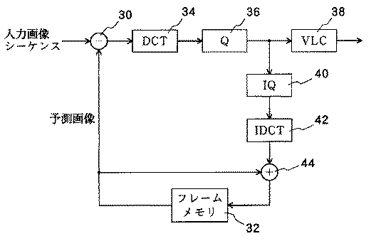
図2は、典型的なMPEG−2符号化器の構成を模式的に示す図である。図2には、PピクチャのMPEG−2符号化を実行する上で、あるいは組み合わされたフレーム間予測とDCT符号化を実行する上で、不可欠の要素を示してある。入力画像データ(入力画像シーケンス)から予測画像を減じるための減算器30が設けられており、入力画像データは減算器30の一方の入力に与えられる。予測画像は、フレームメモリ32内に格納され、減算器30の他方の入力に与えられている。また、符号化器には、減算器30の出力側に接続して離散コサイン変換(DCT)を行うDCT計算器34と、DCT計算器34の出力に接続した量子化器36と、量子化器36の出力がそれぞれ入力される可変長符号化器38および逆量子化器40と、逆量子化器40の出力が入力される逆DCT計算器42と、IDCT計算器42の出力とフレームメモリ32からの(前フレームの)予測画像とを加算してフレームメモリ32に格納する加算器44とが設けられている。
FIG. 2 is a diagram schematically showing a configuration of a typical MPEG-2 encoder. FIG. 2 shows the essential elements for performing MPEG-2 encoding of P-pictures or performing combined inter-frame prediction and DCT encoding. A
減算器30において、入力画像から予測画像が差し引かれる。DCT計算器34は、減算器30からの出力信号に対し、離散余弦変換(DCT)を行い、得られたDCT係数は、量子化装置36で量子化される。量子化装置36の出力である量子化DCT係数は、ハフマン符号化が行われる可変長符号化器38に送られ、このハフマン符号化の結果は、符号列として可変長符号化器38から出力される。量子化DCT係数は、逆量子化装置40にも送られてそこで逆量子化され、この逆量子化されたDCT係数は、逆DCT計算器42によって、逆離散コサイン変換(IDCT;逆DCT)を施される。逆DCTの結果は、加算器44で、フレームメモリ32から出力された予測画像に加算され、これにより、復号器で取得されるものと同じであると予想される画像を再構築する。再構築画像は、「局所復号画像」と称する。この局所復号画像をフレームメモリ32に保存して、予測画像を形成する。
In the
次に、MPEG量子化を補償する方式について述べる。 Next, a method for compensating for MPEG quantization will be described.
図3は、電子透かし入れがなされたデータ内の電子透かしの劣化を低減すべく改良されたMPEG−2符号化器の構成を模式的に示すブロック図である。 FIG. 3 is a block diagram schematically showing a configuration of an MPEG-2 encoder improved to reduce the degradation of digital watermark in digitally watermarked data.
この符号化器は、図2に示す符号化器と比較すると、減算器30の前段側に、入力画像データへのDCTを実行するDCT計算器50と、DCT計算器50の出力に電子透かしを加算する加算器52と、加算器52の出力に対して逆DCTを実行して加算器30に出力する逆DCT計算器54と、予測画像に対してDCTを実行するDCT計算器56と、量子化器36の出力が入力されるもう一つの逆量子化器58と、DCT計算器56の出力と逆量子化器58の出力とを加算する加算器60と、量子化器36からの量子化情報を利用し、加算器60からの出力に基づいて電子透かしの修正を行う電子透かし修正部62と、量子化器36の出力と電子透かし修正部62の出力とを加算する加算器64と、を設けた点で相違し、加算器64の出力が可変長符号化器38および逆量子化器40に入力されている。
This encoder is different from the encoder shown in FIG. 2 in that a
この符号化器では、MPEG−2符号化を行う前に、DCT計算器50において入力画像についてDCTが実行され、加算器52において、DCT計算器50からのDCT係数に電子透かし信号が加算される。電子透かし情報を含む出力DCT係数に対して、逆DCT計算器54で逆DCTが施される。逆DCT計算器54の出力は、電子透かしを含む画像である。これらの電子透かし入れされた画像は、MPEG−2符号化器へ送られ、上述したようにMPEG−2符号化が行われる。さらにこの実施の形態では、MPEG−2圧縮に適合するように、電子透かし情報が修正される。
In this encoder, before performing MPEG-2 encoding, DCT is performed on an input image in a
電子透かし情報の修正に関しては、まず、予測画像についてのDCT係数をDCT計算器56によって計算する。量子化器36から出力された量子化値を、逆量子化器58で逆量子化する。これら逆量子化の結果とDCT計算器56から出力されたDCT係数とは、加算器60によって加算される。この加算結果は、復号器で形成されると予想される復号画像についてのDCT係数と対応する。そのDCT係数は、電子透かし修正部62に入力する。電子透かし修正部62は、電子透かし補正信号を出力する。加算器64は、電子透かし修正部62からの電子透かし補正信号を、量子化器36からの量子化値に加算する。加算装置64の出力は、可変長符号化器38および逆量子化装置40への入力として用いられる。
As for the correction of the digital watermark information, first, the DCT coefficient of the predicted image is calculated by the
次に、電子透かし修正部62で実行される処理について説明する。最初に、この処理を説明するために、いくつかの新たな表記を導入する。D_k[i]に相当する量子化値、すなわち値Vを計算するためのk番目の集合のi番目の項の量子化値をDq_k[i]とする。Dq_k[i]を得る上で使用される量子化ステップサイズの大きさをQ_k[i]とする。逆量子化器58で計算されたDq_k[i]の逆量子化値を、DCT計算器56から出力された対応するDCT係数に加算することで得られる加算器60の出力値を、Dr_k[i]とする。電子透かしの挿入において値V[1,...,N]を計算したのと同じ方法で、加算器60の出力値Dr_k[i]から抽出された値を、Vr[1,...,N]とする。電子透かし修正部62では、ターゲット値ω[1,...,N]も利用可能であると仮定する。
Next, processing performed by the digital
図5は、電子透かし修正部62で実行される処理を説明するフローチャートである。最初に、電子透かし要素の指数(インデックス)kを1に設定する(ステップ500)。次に、Vr[k]の値を下記式によって計算する(ステップ502)。
FIG. 5 is a flowchart illustrating a process performed by the digital
Vr[k]=F_k[1]Dr_k[1]+…+F_k[n_k]Dr_k[n_k]
式中、重み付け係数F_k[1,...,n_k]は、V[k]の計算で使用したものと同じ値である。次に、値Vr[k]とターゲット値ω[k]との間の差の絶対値と、その差の符号を、以下の式によって計算する(ステップ504)。
Vr [k] = F_k [1] Dr_k [1] +... + F_k [n_k] Dr_k [n_k]
In the equation, the weighting coefficients F_k [1, ..., n_k] are the same values as those used in the calculation of V [k]. Next, the absolute value of the difference between the value Vr [k] and the target value ω [k] and the sign of the difference are calculated by the following equation (step 504).
Dif=|Vr[k]−ω[k]|
s=Sign(Vr[k]−ω[k])
ここで、
Dif = | Vr [k] -ω [k] |
s = Sign (Vr [k] -ω [k])
here,
である。 It is.
この値Difは、量子化プロセスにおいて発生した、加算器52で挿入された電子透かしの歪みに対応する。
This value Dif corresponds to the distortion of the digital watermark inserted in the
絶対値Difと符号sに基づいて、ステップ506において、電子透かし補正信号を発生する。ステップ506での処理は後述する。電子透かしのk番目の要素に関係するDCT係数についての電子透かし補正信号の発生の後、ステップ508において指数kをNと比較する。k>Nの場合、処理は終了する。k≦Nの場合、ステップ510で値kを1だけ増加させ、処理をステップ502に戻す。このようにして電子透かし補正処理が行われ、得られた電子透かし補正信号が最終的に加算器64に出力される。
In
次に、図6のフローチャートを用いて、図5のステップ506で実行される処理について、さらに詳しく説明する。このステップ506では、電子透かしのk番目の要素に関係するDCT係数についての電子透かし補正信号を発生する。
Next, the processing executed in
最初に、ステップ520において、配列ΔDq_k[i](i=1,...,n_k)を全てゼロに設定する。次に、ステップ522において、値jを1に設定する。そして、ステップ523において、並べ替え関数p(j)によって、DCT係数の指数(インデックス)iを見出す。関数p(j)は、1からn_kまでの整数を並べ換えた後に得られた順列のj番目の値を返す。最も簡単な例はp(j)=jである。次に、ステップ524において、ΔDq_k[i]に値−sを格納し、値DifをQ_k[i]F_k[i]だけ小さくする。これは、加算器64でΔDq_k[i]をDq_k[i]に加算することで、量子化値Dq_k[i]を−sだけ変化させることを示している。値sは1または−1であり、このことから、量子化値における変化は1である。すなわち、復号器の逆量子化器で得られた逆量子化値は、−Q_k[i]、すなわち1ステップサイズだけ変化する。その更新後の値Difは、補正された量子化値Dq_k[i]+ΔDq_k[i](i=1,...,n_k)を用いて計算したω[k]とVr[k]との間の差の絶対値と同一である。ステップ524の後、ステップ526において、値Difとゼロ、および指数jとn_kとを比較する。Dif<0またはj>n_kの場合、このサブルーチンは終了する。この条件が満足されない場合は、ステップ528で指数jを一定量Δjだけ大きくしてから、処理をステップ523に戻す。
First, in
図6に示した手順ではなく、図7に示した別の手順を、ステップ506の処理手順として用いることができる。図7に示した処理手順では、量子化値Dq_k[i]がゼロであるか否かをチェックするステップ530を、図6におけるステップ523とステップ524の間に加え、ステップ524が、量子化値Dq_k[i]がゼロ以外の値である場合にのみ実行されるようにする。ゼロからゼロ以外の値への量子化値の変更によってビット数が大幅に上昇するのが一般的であることから、これによって、電子透かし情報を補正したことに起因するビット数の上昇を抑えることができる。
Instead of the procedure shown in FIG. 6, another procedure shown in FIG. 7 can be used as the processing procedure of
図4は、電子透かし入れがなされたデータ内の電子透かしの劣化を低減すべく改良された別のMPEG−2符号化器の構成を模式的に示すブロック図である。この符号化器の基本的概念は、図3を用いて説明したものと同じであるが、入力原画像からの予測画像の減算を、空間ドメインではなく、DCTドメイン内で実行している点で相違する。したがって、図4に示す符号化器は、図3に示す符号化器と比較して、減算器30、IDCT計算器54、DCT計算器34,56が設けられておらず、その代わり、予測画像のDCTを実行するDCT計算器70と、加算器52の出力からDCT計算器70の出力を減算する減算器72を設けた構成となっている。減算器72の出力が量子化器36に与えられるとともに、DCT計算器70の出力は加算器60にも与えられている。この符号化器では、入力画像データのMPEG圧縮のためのDCTは、初段のDCT計算器50で行われる。
FIG. 4 is a block diagram schematically showing the configuration of another MPEG-2 encoder improved to reduce the degradation of digital watermark in digitally watermarked data. The basic concept of this encoder is the same as that described with reference to FIG. 3, except that the subtraction of the predicted image from the input original image is performed in the DCT domain instead of the spatial domain. Different. Therefore, the encoder shown in FIG. 4 does not include the
フレームメモリ32から出力された予測画像に対し、DCT計算器70によりDCTが実行され、その結果は、減算器72により、電子透かし入れされたDCT係数から差し引かれる。減算の結果は量子化器36に送られ、その後、図3に示したものと同様にして、電子透かし補正が実行される。減算器72から出力される結果は、DCTの線形性により、図3でのDCT計算器34から出力された結果と同じである。従って、これらの処理とそれに続く量子化器36での量子化によって得られた結果は、図3に示したものと同じである。図4に示す符号化器によれば、図3に示すものよりも、DCT計算の回数が減る。
The DCT is performed on the predicted image output from the
次に、画像内の電子透かしを検出する検出手順について説明する。 Next, a detection procedure for detecting a digital watermark in an image will be described.
MPEGビデオが入力画像データ形式である場合、以下の検出プロセスによって、電子透かしWが存在するか否かを決定する。ここで、W[1,...,N]は、試験対象の電子透かしである。 If the MPEG video is in the input image data format, it is determined whether or not the digital watermark W exists by the following detection process. Here, W [1, ..., N] is a digital watermark to be tested.
ハフマンコードを復号するが、逆DCTは計算しないようにすることで、各フレーム(少なくとも各Iフレーム)に関して、8×8のDCT係数のアレイが得られる。 Decoding the Huffman code, but not computing the inverse DCT, results in an array of 8 × 8 DCT coefficients for each frame (at least each I frame).
次に、電子透かしの挿入時に行ったものと同じDCT係数の加算を行って、ベクトルVを得る。ベクトルVと試験対象の電子透かしWとの間の相関係数Cを以下のように計算する。 Next, the same DCT coefficient as that performed when the digital watermark is inserted is added to obtain a vector V. The correlation coefficient C between the vector V and the digital watermark W to be tested is calculated as follows.
最後に、相関係数Cを正規化フィッシャー(Fisher)Z統計値に変換する。 Finally, the correlation coefficient C is converted into a normalized Fisher Z statistic.
ここでNは電子透かしの長さである。 Here, N is the length of the digital watermark.
Z値は、電子透かしが存在するか否かを示す。Zについての好ましいしきい値は4であるが(すなわち、Z≧4の場合は、電子透かしが存在することを意味する)、間違ったアラームおよび検出の見落としについての所望の発生確率に応じて、他の値を用いることもできる。 The Z value indicates whether a digital watermark exists. The preferred threshold for Z is 4 (ie, if Z ≧ 4, which means that there is a watermark), but depending on the desired probability of occurrence for false alarms and missed detections, Other values can be used.
図8は、MPEG映像入力に対する検出方法を示すデータフロー図である。入力MPEG映像は、ハフマン復号器・パーシャルパーサ80へ送られる。ハフマン復号器・パーシャルパーサ80の出力は、映像入力のn×n、好ましくは8×8の大きさのブロックのDCT係数の集合である。
FIG. 8 is a data flow diagram showing a detection method for an MPEG video input. The input MPEG video is sent to a Huffman decoder /
ハフマン復号器・パーシャルパーサ80から出力するn×nDCT係数は、電子透かしアキュムレータ(蓄積器)82へ与えられる。電子透かしアキュムレータ82は、電子透かしの長さと同じ長さのメモリを備えている。ハフマン復号器・部分パーサ80からのDCT係数は、所定の規則に従って分類され、前述のような電子透かし抽出のために加算され、結果はメモリに蓄積される。抽出された電子透かしは比較器(コンパレータ)84へ与えられ、そこで、前述のように抽出された電子透かしと可能性のある電子透かしとの間の相関係数を計算することにより、画像内にある可能性がある電子透かしと比較される。可能性のある電子透かしとは、映像データ内へ挿入されているであろう電子透かしの全体である。電子透かしアキュムレータやコンパレータの詳細は、例えば、上述した米国特許出願第08/746,022号に記載されている。
The n × n DCT coefficients output from the Huffman decoder /
比較器84の出力は、検出された電子透かしが、ある電子透かしと等しい可能性を表す尤度(正規化されたフィッシャーZ統計値)であり、尤度は可能性のある電子透かしそれぞれに対して算出される。そして、最尤電子透かしが決定され、それが画像内の電子透かしであるとみなされる。あるいは、どの電子透かしに対する尤度も所定のしきい値を越えない場合には、電子透かしは画像中に存在しないと判定する。
The output of the
別法として、入ってくる入力データが非圧縮画像を含む場合、画像全体について8×8DCTを実行することで得られたDCT係数に上記の方法を提供することで、埋め込まれた電子透かしを検出することができる。その場合、各8×8ブロックについてDCTを行わなければならないが、DCT係数をN個の集合に分類する上で精巧に作成された規則によって、DCTを多数回実行することが回避される。DCT計算を減らす方法について説明する前に、いくつかの表記について定義する。 Alternatively, if the incoming input data contains an uncompressed image, detect the embedded watermark by providing the above method to the DCT coefficients obtained by performing an 8 × 8 DCT on the entire image can do. In that case, DCT must be performed for each 8.times.8 block, but the elaborate rules for classifying DCT coefficients into N sets avoid running DCT multiple times. Before describing how to reduce the DCT computation, some notations are defined.
電子透かしの要素の指数(インデックス)kに、8×8DCT係数(i,j)の周波数の指数をマッピングする関数集合をh_m(i,j)(i=1,...,8,j=1,...,8,m=0,...,M−1)とする。Mは関数の数を示す。従って、k=h_m(i,j)の場合、指数が(i,j)であるDCT係数をDCT係数のk番目の集合に分類して、値V[k]を計算する。ここでは、M個の異なる関数h_m(i,j)(m=0,...,M−1)を準備する。ある8×8ブロックについてどの関数を選択するかは、そのブロックの行と列の番号がそれぞれrおよびcで示されるとして、そのブロックの数値rおよびcに依存する。そうして最初に、値rおよびcに従って、関数の指数mを見出し、次に、h_m(i,j)によって、各DCT係数に対する集合の指数kを求める。本明細書において、発明の詳細な説明のここ以降の部分では、DCT係数の分類において、この関数h_m(i,j)を用いるものとする。 A function set for mapping the frequency index of the 8 × 8 DCT coefficient (i, j) to the index (index) k of the element of the digital watermark is represented by h_m (i, j) (i = 1,..., 8, j = 1, ..., 8, m = 0, ..., M-1). M indicates the number of functions. Therefore, when k = h_m (i, j), the DCT coefficient whose index is (i, j) is classified into the k-th set of DCT coefficients, and the value V [k] is calculated. Here, M different functions h_m (i, j) (m = 0,..., M−1) are prepared. Which function to select for a given 8 × 8 block depends on the block's numerical values r and c, assuming that the row and column numbers of the block are denoted by r and c, respectively. Then, first, find the index m of the function according to the values r and c, and then find the index k of the set for each DCT coefficient by h_m (i, j). In this specification, in the rest of the detailed description of the invention, this function h_m (i, j) is used in the classification of DCT coefficients.
この場合、次のようにしてDCT計算の回数を減らすことができる。最初に、指数mが同一であるブロックの和を各m=0,...,M−1について計算する。その加算ブロックをVB_m[i,j](m=0,...,M−1)で表す。次に、M個の加算ブロックVB_m[i,j](m=0,...,M−1)についてDCTを実行する。最後に、加算ブロックのDCT係数を、値h_m(i,j)に従ってN個の集合に分類し、各集合内で加算して、V[1,...,N]を得る。DCTが線形変換であることから、すなわちDCTブロックの合計がブロックの合計についてのDCTの結果に等しいことから、得られた結果V[1,...,N]は、上記の方法によって得られたV[1,...,N]と同じである。Mが画像中のブロックの総数よりかなり小さい場合は、DCT計算の回数は大幅に減少する。そうしてこの方法によって、小さい計算コストで電子透かしを抽出することができる。 In this case, the number of DCT calculations can be reduced as follows. First, the sum of blocks having the same index m is calculated for each m = 0,..., M−1. The addition block is represented by VB_m [i, j] (m = 0,..., M−1). Next, DCT is performed on M addition blocks VB_m [i, j] (m = 0,..., M−1). Finally, the DCT coefficients of the addition block are classified into N sets according to the value h_m (i, j), and added in each set to obtain V [1, ..., N]. Since the DCT is a linear transform, ie, the sum of the DCT blocks is equal to the result of the DCT on the sum of the blocks, the obtained result V [1, ..., N] is obtained by the above method. V [1, ..., N]. If M is much smaller than the total number of blocks in the image, the number of DCT calculations will be greatly reduced. In this way, a digital watermark can be extracted with a small calculation cost by this method.
図9は、上記のような非圧縮映像入力データに対する検出方法を示すデータフロー図である。 FIG. 9 is a data flow diagram showing a detection method for such uncompressed video input data.
非圧縮映像データは、n×nブロックを格納するn×nアキュムレータ、好ましくは8×8ブロックを格納する8×8アキュムレータ90へ、与えられる。メモリの必要量は、関数h_m(i,j)の数のn2倍である。各指数mについて、同じ指数mを有するブロックを加算し、得られたM個の加算ブロックをメモリで蓄積する。
The uncompressed video data is provided to an n × n accumulator that stores n × n blocks, preferably an 8 × 8
出力は、各n×nブロックを加算した信号である。この出力は、DCT計算器92によって、離散コサイン変換が施される。変換の回数は、関数h_m(i,j)の数に比例する。変換結果は、n×nDCTの一群であり、関数h_m(i,j)に従ってN個の集合に分類され、加算されて、上述の電子透かし抽出が行われる。得られた電子透かしは、電子透かしアキュムレータ94に供給され、蓄積される。電子透かしアキュムレータ94についてのメモリの必要量は、電子透かしの長さに比例する。抽出された電子透かしは、入力として比較器96に供給される。比較器96への他の入力は、入力画像データに挿入されているかもしれない、と考えられる電子透かしである。比較器は、各考えられる電子透かしごとにその電子透かしが画像データ中に挿入されている確率(正規化フィッシャーZ統計値)すなわち尤度を計算する。最も可能性の高い電子透かし(最尤電子透かし)が決定され、それが画像中の電子透かしであるみなされる。
The output is a signal obtained by adding each of the n × n blocks. This output is subjected to a discrete cosine transform by the
ブロックに基づくDCT法の限界は、画像の空間シフトに対するその感受性である。例えば、画像が右方向に2画素移動すると、DCT係数が大幅に変わるために、電子透かしを検出することができない。さらに、スケーリングや回転などの一般的な変形によっても、電子透かしを検出できなくなる。 A limitation of the block-based DCT method is its sensitivity to spatial shift of the image. For example, when the image moves two pixels to the right, the DCT coefficient changes significantly, so that the digital watermark cannot be detected. Furthermore, digital watermarks cannot be detected due to general deformations such as scaling and rotation.
これらの問題を解決するため、上記の挿入方法および抽出方法を、2つの方法で修正することができる。第1の可能な変更点は、映像の規定された歪みに耐えるように設計された複数の電子透かしを画像データに挿入することであり、第2の変更点は、複数回の加算を行うことなく、並進を補償できるよう配置するというものである。必要に応じて、その第2の変更点は、映像の任意の並進を補償するために、改良された電子透かし検出器が使用することができるレジストレーションパターンを各電子透かしに対応して1つずつ挿入するように、さらに修正することができる。 To solve these problems, the above insertion and extraction methods can be modified in two ways. The first possible change is to insert multiple watermarks into the image data designed to withstand the specified distortion of the video, the second change is to perform multiple additions Instead, they are arranged so that translation can be compensated. Optionally, the second change is that the improved watermark detector can use a registration pattern, one for each watermark, that can be used to compensate for any translation of the video. Further modifications can be made so that they are inserted one by one.
上述の基本的な方法を用いて挿入された電子透かしを検出する場合、電子透かしの挿入時に使用されたのと同じn×nブロックのグリッドに基づいて、画像を分割する必要がある。ここでn×nブロックのグリッドとは、画像をn画素×n画素の複数のブロックに分割する際のブロック間の境界となるべき線のことである。電子透かしの挿入後に画像が並進していれば、電子透かしの検出時に、挿入時のグリッドに適合するように正しくグリッドを決定することが困難となる。多くの応用において、ある特定のこのような変換が画像に施されることが考えられるため、これは重要な問題である。例えば、DVD(デジタル・ビデオ・ディスク;digital Video Disk)に記録された映像は、“パンスキャン(panscan)”もしくは“レターボックス(letterbox)”モードへ変換し、これによってこの映像を標準テレビ画面に適合するように修正することが考えられる。“パンスキャン”モードでは、水平解像度が高くなり、画面は所定のオフセットで切り取られて、得られる画像は3×4アスペクト(縦横)比のテレビ画面上で見る時に正しくなるようにされる。“レターボックス”モードでは、画像は垂直にスケーリング(この場合は縮小)され、画面の上端部および下端部に黒が加えられて、全体画像が3×4アスペクト比の画面に正しく適合するようにされる。これら2つの幾何学的変換は、他の変換よりも多く使用されるため、特にこれらパンスキャンモードおよびレターボックスモードへの変換に対応できるようにすることが妥当である。 When detecting a digital watermark inserted using the above-described basic method, it is necessary to divide an image based on the same grid of n × n blocks used when inserting the digital watermark. Here, the grid of n × n blocks is a line to be a boundary between blocks when an image is divided into a plurality of blocks of n × n pixels. If the image is translated after the digital watermark is inserted, it is difficult to correctly determine the grid so as to match the grid at the time of the digital watermark detection. This is an important issue since in many applications it is possible that certain such transformations will be applied to the image. For example, a video recorded on a DVD (Digital Video Disk) is converted to a "panscan" or "letterbox" mode, whereby the video is displayed on a standard television screen. Modifications to suit may be possible. In the "pan scan" mode, the horizontal resolution is increased and the screen is cropped at a predetermined offset so that the resulting image is correct when viewed on a 3.times.4 aspect ratio television screen. In "letterbox" mode, the image is scaled vertically (reduced in this case) and black is added at the top and bottom of the screen to ensure that the entire image fits properly on a 3x4 aspect ratio screen. Is done. Since these two geometric transformations are used more often than the other transformations, it is especially appropriate to be able to accommodate these transformations to pan scan mode and letterbox mode.
電子透かし入れされた映像への所定のスケーリングや変換の問題は、本発明により、使用頻度の高い各変換に対応して付加的な電子透かしを挿入することにより解決される。これらの各付加的な電子透かしは、電子透かしの挿入後に画像に対して対応する既知の変換を行う場合に、電子透かしの挿入時に使用したn×nブロックのグリッドが、検出時に使用される所定のグリッドと一致するように設計されている。したがって、例えばDVDの場合、画像に対して変換が施されない場合には、検出時のグリッドは(何の変換もうけていない)通常の電子透かしのものと一致し、通常の電子透かしが検出される。付加的な電子透かしとして、“パンスキャン”用の電子透かしを挿入しておけば、画像に対して“パンスキャン”変換を行うと、検出時のグリッドが“パンスキャン”用の電子透かしのものと一致し、“パンスキャン”用の電子透かしが検出される。“レターボックス”変換もしくは任意他の所定の変換についても同様に、対応する付加的な電子透かしを挿入することによって対処できるようになる。 The problem of predetermined scaling and conversion to watermarked video is solved by the present invention by inserting additional watermarks corresponding to each frequently used conversion. Each of these additional watermarks, when performing a corresponding known transformation on the image after the watermark is inserted, uses the grid of n × n blocks used at the time of the watermark insertion to a predetermined grid used at the time of detection. Designed to match the grid. Therefore, in the case of a DVD, for example, when the image is not converted, the grid at the time of detection matches that of a normal digital watermark (no conversion is made), and a normal digital watermark is detected. . As an additional digital watermark, if a digital watermark for “pan scan” is inserted, if “pan scan” conversion is performed on the image, the grid at the time of detection will be a digital watermark for “pan scan”. And an electronic watermark for “pan scan” is detected. The "letterbox" conversion or any other predetermined conversion can likewise be addressed by inserting a corresponding additional watermark.
特定の変換を行った後に検出される電子透かしの挿入手順には、下記のステップが含まれる。 The procedure for inserting a digital watermark detected after performing a specific conversion includes the following steps.
1. 電子透かし入れされる画像IのコピーITを生成し、補償対象となる変換を画像に適用する。例えば、ITは、垂直方向に収縮することにより画像Iを“レターボックス”モードへ変換したもののコピーになる。 1. Generating a copy I T of the image I to be watermarked, apply the transformation to be compensated for the image. For example, IT is a copy of image I converted to "letterbox" mode by contracting vertically.
2. 上述した一般的な電子透かし入れ方法にしたがって、変換された画像IT’の電子透かし入れされたバージョンを生成する。 2. Generate a watermarked version of the transformed image IT 'according to the general watermarking method described above.
3. 電子透かし挿入後の画像IT’から挿入前の画像ITを減じ、電子透かし挿入によって生じる差分WT=IT’−ITを空間ドメインで求める。 3. 'Reducing the image I T before insertion from differential W T = I T generated by the watermarking' image I T after insertion watermark seek -I T in the spatial domain.
4. 差分WTに対して画像Iから画像ITを求めたときの逆変換を実施して、変換前の画像Iに対応する差分画像Wを得る。例えば、補償すべき変換が“レターボックス”モードへの変換であった場合には、WTを垂直に拡張してWが得られる。 4. The inverse conversion when the image I T is obtained from the image I is performed on the difference W T to obtain a difference image W corresponding to the image I before the conversion. For example, if the conversion to be compensated was converted into "letterbox" mode, W is obtained by expanding the W T vertically.
5. I’=I+Wを、所与の変換のための電子透かしが付加された画像とする。 5. Let I '= I + W be the image to which the digital watermark for a given transform has been added.
電子透かし入り画像I’に変換が適用されると、結果はほぼIT’となる。その結果、電子透かし挿入時に用いたグリッドが通常のグリッドに一致するようになるため、通常の電子透かしを検出するように設計された同じ手順により、電子透かしが検出される。 When the transformation is applied to the watermarked image I ', the result is approximately I T '. As a result, since the grid used at the time of inserting the digital watermark matches the normal grid, the digital watermark is detected by the same procedure designed to detect the normal digital watermark.
このようにして、複数の付加的な電子透かしを挿入すると画像が劣化し、かつ画像内の他の電子透かしの検出可能性(検出度)が低下するため、この手順は考慮する変換の数が少ない場合にしか使用できない。しかしながら、3つの電子透かし、すなわち、変換された画像に対する2つの電子透かしと変換されない画像に対する1つの電子透かしを挿入した場合であっても、画像の忠実度を許容できる範囲内に保ちながら電子透かしの良好な検出度が得られることが、テストにより判明した。別法として、ビデオについては、各電子透かしを時間多重の形態で挿入することができる。 In this way, the insertion of multiple additional watermarks degrades the image and reduces the detectability (detection) of other watermarks in the image. Can be used only when there are few. However, even when three digital watermarks are inserted, ie, two digital watermarks for the converted image and one digital watermark for the non-converted image, the digital watermark is maintained while maintaining the image fidelity within an acceptable range. It was found by tests that a good degree of detection was obtained. Alternatively, for video, each watermark can be inserted in a time multiplexed manner.
画像に対して行われる変換が規定されていないもしくは予め定められていないか、あるいは、各変換ごとに独立した電子透かしを挿入するとしてそのような変換が非常に多くあることが考えられる場合には、上述した変換補償方法は最適ではない。したがって、本発明には、電子透かしの挿入時と電子透かしの検出時との間で画像に対して加えられた任意の並進を補償する改良が、加えられている。 If the conversion to be performed on the image is not specified or predetermined, or if it is considered that there are too many such conversions by inserting an independent digital watermark for each conversion The conversion compensation method described above is not optimal. Accordingly, the present invention includes an improvement that compensates for any translation applied to the image between the time of insertion of the watermark and the time of detection of the watermark.
任意の並進は、2つの方法で補償される。一つの方法は、8×8ブロックを使用した場合における、x方向またはy方向の8ピクセルのちょうど整数倍だけの距離の並進によるものである。関数h_m(i,j)の指数mとブロックの行rおよび列cとの間の関係に以下の制約を課すことによって、任意の並進を容易に補償することができる。まず、下記式によって、指数mを求める。 Any translation is compensated in two ways. One method is by translating a distance that is exactly an integer multiple of 8 pixels in the x or y direction when using 8 × 8 blocks. Any translation can be easily compensated by imposing the following constraints on the relationship between the index m of the function h_m (i, j) and the row r and column c of the block. First, an index m is obtained by the following equation.
m=f(r,c) mod M
式中、f(r,c)はrおよびcの線形関数であり、f(0,1)およびf(1,0)は整数である。さらに、h_m(i,j)を下記式で表される関数とする。
m = f (r, c) mod M
Where f (r, c) is a linear function of r and c, and f (0,1) and f (1,0) are integers. Further, let h_m (i, j) be a function represented by the following equation.
h_m(i,j)=(h_0(i,j)+a×m) mod N
式中、aは整数である。
h_m (i, j) = (h_0 (i, j) + a × m) mod N
Wherein a is an integer.
本明細書のここ以降の部分においては、ここで述べた制約条件を仮定する。この場合、試験対象の電子透かしの全ての巡回シフトと抽出された電子透かしとの相関を計算することによる基本検出アルゴリズムにより、シフト補償を実行する。それは、水平方向および/または垂直方向に8の倍数画素だけ移動した電子透かし入れされた画像から得られたVB_m[i,j]値が、指数mを巡回シフトしている点を除き、移動前の画像から得られる値VB_m[i,j](m=0,...,M−1)と同一であるためである。結果的に、8の複数倍画素だけ移動した電子透かし入れされた画像から得られる抽出値V[1,...,N]は、要素V[k]が巡回シフトされている点を除き、移動前の画像から得られる値V[1,...,N]と同一である。n×nグリッド形式の場合、水平方向および/または垂直方向でのnの複数倍の移動に同じことが当てはまる。 In the remainder of this specification, the constraints described here are assumed. In this case, shift compensation is performed by a basic detection algorithm by calculating the correlation between all the cyclic shifts of the digital watermark to be tested and the extracted digital watermark. It is the same as before moving, except that the VB_m [i, j] values obtained from the watermarked image moved horizontally and / or vertically by a multiple of 8 pixels are cyclically shifted by an index m. Is the same as the value VB_m [i, j] (m = 0,..., M−1) obtained from the image of FIG. As a result, the extracted values V [1, ..., N] obtained from the digitally watermarked image shifted by a multiple of 8 pixels, except that the element V [k] is cyclically shifted. It is the same as the value V [1, ..., N] obtained from the image before the movement. In the case of the nxn grid format, the same applies to multiple multiples of n in the horizontal and / or vertical directions.
x方向および/またはy方向への8画素よりも少ない整数画素精度のシフトに対しては、全部で64(=82)通りの考えられる場合の全数探索を実施して、64×M個のZ値(尤度)の組の中から最大のZ値を取り出す。Mは8×8アキュムレータの数である。本発明者らのテストでは、Mとして64を選択した。ここでMをかけているのは、各シフトに対する検出では、M通りの巡回シフトを考慮するためである。これによって、8画素よりも少ないシフト量を求めることができる。 For a shift of integer pixel precision less than 8 pixels in the x and / or y directions, a total of 64 (= 8 2 ) possible exhaustive searches are performed to find 64 × M The maximum Z value is extracted from the set of Z values (likelihood). M is the number of 8 × 8 accumulators. In our tests, 64 was selected as M. Here, M is multiplied in order to consider M cyclic shifts in the detection for each shift. Thus, a shift amount smaller than eight pixels can be obtained.
全数探索では、空間ドメイン内のM個の8×8アキュムレータアレイの値をシフトさせ、次にM個の8×8ブロックの各々のDCTを実施する必要がある。これは考えられる各シフトごとに1回ずつ、計64回実施される。したがって、64×M回の8×8DCTを実施する必要がある。Mの値が大きく、この計算に時間や費用がかかり過ぎる場合には、後述する代わりの方法を使用することができる。 An exhaustive search requires shifting the values of the M 8 × 8 accumulator arrays in the spatial domain, and then performing a DCT on each of the M 8 × 8 blocks. This is done 64 times, once for each possible shift. Therefore, it is necessary to perform 64 × M 8 × 8 DCTs. If the value of M is large and this calculation is too time-consuming and expensive, alternative methods described below can be used.
n画素の非整数倍の並進を補償する第2の方法は、電子透かし挿入と検出とでグリッドを合わせるためのパターンを用いる方法である。このパターンのことをレジストレーション(位置決め)パターンと呼ぶことにする。レジストレーションパターンは、電子透かしの挿入時に挿入することができる。電子透かしの検出時に、レジストレーションパターンが予め規定されたパターンと最も一致する位置を見つけることにより、復号器は、電子透かしを抽出する前にどれだけデータをシフトすべきかを決定することができる。このシフトは空間ドメインで行わなければならないが、後述するように、アキュムレータにより実施することができ、それによって、画像全体のブロック全てに対して変換を行うことが回避される。 A second method for compensating for a translation of a non-integer multiple of n pixels is a method using a pattern for matching a grid between digital watermark insertion and detection. This pattern is called a registration (positioning) pattern. The registration pattern can be inserted when inserting a digital watermark. By finding the position where the registration pattern best matches the predefined pattern when detecting the watermark, the decoder can determine how much data should be shifted before extracting the watermark. This shift must be performed in the spatial domain, but can be performed by an accumulator, as described below, thereby avoiding performing the transform on all blocks of the entire image.
また、この方法では、64×M回の8×8DCTを計算する必要はなく、代わりに、正しい位置決めを空間ドメイン内で行い、アキュムレータアレイ内で画素をシフトすることにより、画像の並進の補償がなされる。M個の8×8アキュムレータだけがDCTドメインに変換され、上述したようにして電子透かしの抽出が実行される。 Also, this method does not require the computation of 64 × M 8 × 8 DCTs, but instead compensates for image translation by performing correct positioning in the spatial domain and shifting pixels in the accumulator array. Done. Only the M 8 × 8 accumulators are transformed into the DCT domain, and the extraction of the digital watermark is performed as described above.
レジストレーションパターンは、8×8画素ブロックの全部の和がそのパターンと強く相関するように画像中に挿入された、8×8空間パターンである。ビデオがn×nブロックである場合は、n×n空間パターンを用いる。レジストレーションパターンは、上述した電子透かし挿入方法を用いることで挿入することができる。全ての8×8画素ブロックを合計してできる合計ブロックとレジストレーションパターンのDCT係数同士が相互に大きな相関を有する場合、合計ブロックは、レジストレーションパターンと高い相関性を有するようになる。さらに、合計ブロックのDCT係数は、DCTの線形性により、全DCTブロックの合計に等しい。そのようにして、レジストレーションパターンのDCT係数を電子透かしWとみなし、全ての8×8DCTブロックの合計を値Vとみなすことにより、上記の電子透かし挿入方法と類似の方法を用いて、レジストレーションパターンを挿入することができる。 The registration pattern is an 8 × 8 spatial pattern inserted into the image such that the sum of all 8 × 8 pixel blocks strongly correlates with the pattern. If the video is n × n blocks, use an n × n spatial pattern. The registration pattern can be inserted by using the above-described digital watermark insertion method. When the total block formed by summing all the 8 × 8 pixel blocks and the DCT coefficients of the registration pattern have a large correlation with each other, the total block has a high correlation with the registration pattern. Furthermore, the DCT coefficient of the sum block is equal to the sum of all DCT blocks due to the linearity of the DCT. In this way, the DCT coefficient of the registration pattern is regarded as the digital watermark W, and the sum of all the 8 × 8 DCT blocks is regarded as the value V. Patterns can be inserted.
レジストレーションパターンをDCTドメインへ変換し、次に、DCT係数Dkおよびフィルタ係数Fkが異なる上述の基本的な挿入アルゴリズムを使用することによって、レジストレーションパターンの挿入が実施される。ここでは、レジストレーションパターンのDCT係数での各AC(交流)項は、電子透かしの1つの要素W[k]と考えられる。すなわち、指数(インデックス)kは、DCT係数の周波数インデックスそのものに相当する。したがって、この要素を抽出するために一緒に合計される1組のDCT係数Dkは、単純に、W[k]と同じ周波数指数をもつ画像内の8×8DCT係数の全てである。そして、全てのFkが1に設定される。これらのDkおよびFkを使用して、挿入アルゴリズムによりレジストレーションパターンが、画像データに挿入される。これと一緒に、元のDkおよびFkによる電子透かしも挿入される。 The insertion of the registration pattern is performed by transforming the registration pattern into the DCT domain and then using the basic insertion algorithm described above, where the DCT coefficients D k and the filter coefficients F k are different. Here, each AC (alternating current) term in the DCT coefficient of the registration pattern is considered to be one element W [k] of the digital watermark. That is, the index (index) k corresponds to the frequency index itself of the DCT coefficient. Thus, the set of DCT coefficients D k summed together to extract this element is simply all of the 8 × 8 DCT coefficients in the image with the same frequency index as W [k]. Then, all F k are set to 1. Using these D k and F k , a registration pattern is inserted into the image data by an insertion algorithm. At the same time, a digital watermark with the original D k and F k is also inserted.
検出中に、下記のようにレジストレーション処理が実施される。まず、所定数のブロックを合計して、典型的には8×8である、単一のn×n画素ブロックを形成する。本発明者らの試験では、適宜に64個のブロックを使用した。この単一のブロックは、挿入過程によってそこに配置されたレジストレーションパターンを含んでいる。次に、フレームの水平方向及び垂直方向の並進量を決定するために、空間ドメインにおいて8×8画素平均ブロックとレジストレーションパターンとの相関を調べる処理(以後相関プロセスと呼ぶ)を実施し、これらの並進によるオフセットを決定する。可能である8通りの水平並進量及び8通りの垂直並進量の各々について相関プロセスが実施され、計64回の相関プロセスが実施される。8×8パッチ領域を水平方向または垂直方向にシフトする際、ラップアラウンドシフト、すなわち前と重なり合うようなシフト動作が実施される。 During detection, a registration process is performed as described below. First, a predetermined number of blocks are summed to form a single n × n pixel block, typically 8 × 8. In our tests, 64 blocks were used as appropriate. This single block contains the registration pattern placed there by the insertion process. Next, in order to determine the horizontal and vertical translation amounts of the frame, a process of examining the correlation between the 8 × 8 pixel average block and the registration pattern in the spatial domain (hereinafter referred to as a correlation process) is performed. To determine the translation offset. The correlation process is performed for each of the eight possible horizontal and eight vertical translations, for a total of 64 correlation processes. When shifting the 8 × 8 patch area in the horizontal direction or the vertical direction, a wrap-around shift, that is, a shift operation that overlaps with the previous one is performed.
ここで、グリッドの移動の求め方について説明する。以下の方法では、整数値f(0,1)およびf(1,0)がMに対しては互いに素であると仮定する。 Here, how to determine the movement of the grid will be described. In the following method, it is assumed that the integer values f (0,1) and f (1,0) are relatively prime to M.
最初に、DCT係数の分類において同じ関数h_m(i,j)が用いられるブロックを、空間ドメイン内で一緒に加算して、各mについて1つの合計ブロックVB_m[i,j]を得る。AB[i,j]によって示される、全てのn×n個のブロックについての合計を、下記式によって計算する。 First, the blocks in which the same function h_m (i, j) is used in the classification of DCT coefficients are added together in the spatial domain to obtain one total block VB_m [i, j] for each m. The sum for all n × n blocks, denoted by AB [i, j], is calculated by the following equation.
次に、R[i,j]によって表されるレジストレーションパターンとAB[i,j]との間の相関係数を計算する。この相関係数の計算後、値AB[i,j]を水平方向に1列だけ巡回シフトさせ、AB[i,j]とR[i,j]との間の相関係数を同様に計算する。各シフトについて同じ演算を繰り返す。n回シフトさせた後、AB[i,j]は、最初のシフトを行う前のAB[i,j]と同一となる。次に、値AB[i,j]を垂直方向に1行だけ巡回シフトさせ、相関係数の計算と水平方向への1列だけのシフトを繰り返す。このようにして、全てのn2個の可能なシフトについての相関係数を計算することができる。同時に、最大の相関係数を与える、(X,Y)で表されるシフト値(オフセット)を調べる。 Next, a correlation coefficient between the registration pattern represented by R [i, j] and AB [i, j] is calculated. After calculating the correlation coefficient, the value AB [i, j] is cyclically shifted by one column in the horizontal direction, and the correlation coefficient between AB [i, j] and R [i, j] is similarly calculated. I do. The same operation is repeated for each shift. After shifting n times, AB [i, j] is the same as AB [i, j] before the first shift. Next, the value AB [i, j] is cyclically shifted by one row in the vertical direction, and the calculation of the correlation coefficient and the shift of one column in the horizontal direction are repeated. In this way, the correlation coefficients for all n 2 possible shifts can be calculated. At the same time, the shift value (offset) represented by (X, Y) that gives the maximum correlation coefficient is examined.
オフセット(X,Y)を求めた後、それに応じて、M個の合計ブロックVB_m[i,j]を空間ドメインでシフトさせる。 After obtaining the offset (X, Y), the M total blocks VB_m [i, j] are shifted in the spatial domain accordingly.
次に、水平方向でのシフト値Xを補償する方法を説明する。この補償を行うためには、最初に、値VB_m[i,j](m=0,...,M−1)を、n×nMの配列VB1[i,j](i=1,...,n,j=1,...,nM)にコピーする。値VB_m[i,j]をコピーする際に、ブロック間の空間的関係、すなわちあるブロックがどのブロックに隣接しているかを考慮する。関数f(r,c)は線形であることから、下記式のようになる。 Next, a method for compensating the shift value X in the horizontal direction will be described. In order to perform this compensation, first, the value VB_m [i, j] (m = 0,..., M−1) is converted into an n × nM array VB1 [i, j] (i = 1,. .., n, j = 1,..., nM). When copying the value VB_m [i, j], the spatial relationship between blocks, that is, which block a certain block is adjacent to, is considered. Since the function f (r, c) is linear, the function is represented by the following equation.
f(r,c+1)=f(r,c)+f(0,1)
これは、指数mが
m1=(m0+f(0,1)) mod M
に等しいブロックが、m=m0であるブロックに隣接していることを意味している。そこで、行列VB1において、値VB_m1を値VB_m0の隣りにコピーする。そのため、各I(I=0,...,M−1)について、VB_m’[i,j](i=1,...,n,j=1,...,n,m’=I×f(0,1) mod M)を、左上の角の指数を(1,nI+1)とする、VB1内のn×nの正方形領域にコピーする。全ての値Iをコピーした後、f(0,1)とMが互いに素であることから、配列VB1は値VB_m[i,j]で埋まる。次に、配列VB1中の値を水平方向にXだけ巡回シフトさせる。
f (r, c + 1) = f (r, c) + f (0,1)
This means that the index m is m1 = (m0 + f (0,1)) mod M
Is adjacent to the block where m = m0. Therefore, the value VB_m1 is copied next to the value VB_m0 in the matrix VB1. Therefore, for each I (I = 0, ..., M-1), VB_m '[i, j] (i = 1, ..., n, j = 1, ..., n, m' = I × f (0,1) mod M) is copied to an n × n square area in VB1 where the index of the upper left corner is (1, nI + 1). After copying all the values I, the array VB1 is filled with the values VB_m [i, j] because f (0,1) and M are relatively prime. Next, the values in array VB1 are cyclically shifted by X in the horizontal direction.
次に、左上の角の指数が(1,nI+1)であるVBI中のn×n領域における値を、各I(I=0,...,M)について、VB_m’[i,j](i=1,...,n,j=1,...,n,m’=I×f(0,1) mod M)に代入することで、VB1における値をVB_mに返す。こうして、全体画像自体をシフトさせることなく、水平方向オフセット値Xを補償することができる。 Next, the value in the n × n region in the VBI in which the index of the upper left corner is (1, nI + 1) is calculated as VB_m ′ [i, j] (for each I (I = 0,..., M)). By substituting i = 1,..., n, j = 1,..., n, m ′ = I × f (0,1) mod M), the value in VB1 is returned to VB_m. In this manner, the horizontal offset value X can be compensated without shifting the entire image itself.
次に、垂直方向における移動値Yを補償する。この補償を行うには、まず、値VB_m[i,j](m=0,...,M−1)をnM×nの配列VB2[i,j](i=1,...,nM,j=1,...,n)にコピーする。値VB_m[i,j]をコピーする際に、ブロック間の空間的関係を考慮する。関数f(r,c)が線形であることから、下記式のようになる。 Next, the movement value Y in the vertical direction is compensated. To perform this compensation, first, the value VB_m [i, j] (m = 0,..., M−1) is converted into an nM × n array VB2 [i, j] (i = 1,. nM, j = 1,..., n). When copying the value VB_m [i, j], the spatial relationship between blocks is taken into account. Since the function f (r, c) is linear, the following equation is obtained.
f(r+1,c)=f(r,c)+f(1,0)
これは、指数mが
m1=(m0+f(1,0))mod M
に等しいブロックが、m=m0であるブロック下にあることを意味している。そこで、行列VB2において、値VB_m1を値VB_m0下にコピーする。そのため、各I(I=0,...,M−1)に対して、VB_m’[i,j](i=1,...,n,j=1,...,n,m’=I×f(0,1) mod M)を、左上の角の指数を(nI+1,1)とする、VBI内のn×nの正方形領域にコピーする。全ての値Iをコピーした後、f(1,0)とMが互いに素であることから、配列VB2は値VB_m[i,j]で埋まる。次に、配列VB2中の値を垂直方向にYだけ巡回シフトさせる。
f (r + 1, c) = f (r, c) + f (1,0)
This means that the index m is m1 = (m0 + f (1,0)) mod M
Means that the block is below the block where m = m0. Therefore, in the matrix VB2, the value VB_m1 is copied below the value VB_m0. Therefore, for each I (I = 0, ..., M-1), VB_m '[i, j] (i = 1, ..., n, j = 1, ..., n, m '= I × f (0,1) mod M) is copied to an n × n square area in the VBI, where the index of the upper left corner is (nI + 1,1). After copying all the values I, the array VB2 is filled with the values VB_m [i, j] because f (1,0) and M are relatively prime. Next, the values in array VB2 are cyclically shifted by Y in the vertical direction.
次に、VB2中の左上の角の指数が(nI+1,1)であるn×n領域における値を、各I(I=0,...,M)について、VB_m’[i,j](i=1,...,n,j=1,...,n,m’=I×f(0,1) mod M)に代入することで、VB2における値をVB_mに返す。こうして、全体画像自体をシフトさせることなく、垂直方向オフセット値Yを補償することができる。 Next, the value in the n × n region where the exponent of the upper left corner in VB2 is (nI + 1,1) is calculated for each I (I = 0,..., M) by VB_m ′ [i, j] ( By substituting i = 1,..., n, j = 1,..., n, m ′ = I × f (0,1) mod M), the value in VB2 is returned to VB_m. Thus, the vertical offset value Y can be compensated without shifting the entire image itself.
n×nグリッドのオフセットは、上記の処理によって補償される。これらの処理は、後述のように、図10のレジストレーション処理108で行われる。nの倍数の移動はこれらの処理を行った後にも残っているが、上述したように電子透かしを巡回的にシフトさせることによって電子透かしWと抽出値Vとの間の相関係数が計算されるので、そのシフトは電子透かしの検出には影響を及ぼさない。以上のレジストレーション処理を適用した後、M個のブロックVB_m(m=0,...,M−1)をDCTドメインに変換し戻す。
The offset of the nxn grid is compensated by the above processing. These processes are performed in a
図10および図11は、それぞれ、MPEG映像入力の場合と非圧縮映像(伸長された映像)の場合における、並進レジストレーションを補償するように修正された基本的な検出アルゴリズムを示している。 FIGS. 10 and 11 show the basic detection algorithm modified to compensate for translational registration for MPEG video input and uncompressed video (decompressed video) cases, respectively.
MPEG映像入力の場合(図10)、最初に、MPEGビデオストリームから得られる8×8DCTブロックを、関数h_m(i,j)の指数mに従ってM個のグループに分類し、M個の合計ブロックを生成するためにグループ内で加算し、その後、得られた合計ブロックを8×8アキュムレータ102で蓄積する。次に、8×8アキュムレータ102内のM個の合計ブロックは、逆DCT変換器104で逆DCT演算を行うことで空間ドメインに変換され、8×8アキュムレータ106に蓄積される。8×8グリッドのオフセット値の検索とそのオフセットの補償を、上記の方法に従って、レジストレーション処理108において、8×8アキュムレータ106からの出力について実行する。レジストレーション処理108から出力されたレジストレーションデータは、8×8アキュムレータ110に蓄積され、DCT変換器112によってDCTドメインに変換される。DCT変換器112の出力に対し、8×8アキュムレータ114、電子透かし抽出器116および電子透かし復号器118を使用して、電子透かし抽出が行われる。
In the case of MPEG video input (FIG. 10), first, the 8 × 8 DCT blocks obtained from the MPEG video stream are classified into M groups according to the index m of the function h_m (i, j), and the M total blocks are Additions within a group to generate, and then accumulate the resulting total block in an 8 × 8 accumulator 102. Next, the M total blocks in the 8 × 8 accumulator 102 are converted to the spatial domain by performing an inverse DCT operation in the
電子透かし抽出器116では、8×8アキュムレータ114から出力されたDCT係数が、関数h_m(i,j)に従ってN個の集合に分類され、加算され、これによって電子透かし抽出が行われる。得られた電子透かしは電子透かし復号器118に出力される。電子透かし復号器118は、抽出された電子透かしに対応する電子透かしを検索するために、図8に示す比較器84での処理を実行する。挿入されたと考えられる電子透かしが、電子透かし復号器118から出力される。
In the
非圧縮データの場合は(図11)、入力データが、8×8のブロックに分割され、関数h_m(i,j)の指数に従って8×8アキュムレータ106に蓄積される。その後、レジストレーション処理108を行ってから、DCT変換器112でDCTドメインに変換され、その後は、MPEG映像の場合と同様に処理が行われる。
In the case of uncompressed data (FIG. 11), the input data is divided into 8 × 8 blocks and stored in the 8 × 8
30,72 減算器
32 フレームメモリ
34,50,56,70, DCT計算器
36 量子化器
38 可変長符号化器
40,58 逆量子化器
42,54 逆DCT計算器
44,52,60,64 加算器
62 電子透かし修正部
80 ハフマン復号器・パーシャルパーサ
82,94 電子透かしアキュムレータ(蓄積器)
84,96 比較器
90,102,106,110,114 8×8アキュムレータ
92,112 DCT変換器
104 逆DCT変換器
108 レジストレーション処理
116 電子透かし抽出器
118 電子透かし復号器
30, 72
84,96 Comparator 90,102,106,110,114 8 × 8 accumulator 92,112
Claims (31)
電子透かし入れがなされているデータの前記複数のn×nブロックを合計して、少なくとも1つのn×nブロックの合計電子透かしデータを作成するステップと、
前記ブロックを空間ドメイン内で巡回的にシフトして前記ブロックの位置合わせを行なうステップと、
前記少なくとも1つのn×nブロックから電子透かしを抽出するステップと、を有する、
電子透かし入れがなされたデータから電子透かしを検出する方法。 Receiving the watermarked data having a plurality of n × n blocks of the watermarked data;
Summing the plurality of n × n blocks of the watermarked data to generate total watermark data of at least one n × n block;
Cyclically shifting the block in the spatial domain to align the block;
Extracting a watermark from the at least one nxn block.
A method of detecting a digital watermark from digitally watermarked data.
電子透かし入れがなされているデータの前記複数のn×nブロックを合計して、少なくとも1つのn×nブロックの合計電子透かしデータを作成するステップと、
各n×nブロックからの所定の電子透かし入れされたデータを合計して、抽出された電子透かしの各要素を生じることにより、前記少なくとも1つのn×nブロックから電子透かしを抽出するステップと、を有する、
電子透かし入れがなされたデータから電子透かしを検出する方法。 Receiving the watermarked data having a plurality of n × n blocks of the watermarked data;
Summing the plurality of n × n blocks of the watermarked data to generate total watermark data of at least one n × n block;
Extracting a watermark from said at least one nxn block by summing predetermined watermarked data from each nxn block to produce each element of the extracted watermark; Having,
A method of detecting a digital watermark from digitally watermarked data.
周波数指数から電子透かしの要素の指数上にマッピングを行う関数の数をMとして、電子透かし入れがなされているデータの前記複数のn×nブロックを合計して、M個のn×nブロックの合計電子透かしデータを作成するステップと、
少なくとも1つのn×nブロックから電子透かしを抽出するステップと、を有する、
電子透かし入れがなされたデータから電子透かしを検出する方法。 Receiving the watermarked data having a plurality of n × n blocks of the watermarked data;
Assuming that the number of functions for performing mapping from the frequency index on the exponent of the element of the digital watermark is M, the plurality of n × n blocks of the digitally watermarked data are summed, and Creating total digital watermark data;
Extracting a watermark from at least one nxn block.
A method of detecting a digital watermark from digitally watermarked data.
前記入力ビデオ画像に対して離散余弦変換(DCT)を行って、入力ビデオ画像DCT値を得るステップと、
前記入力ビデオ画像DCT値に電子透かし信号を加えて、電子透かし入りDCT値を得るステップと、
前記電子透かし入りDCT値に対して逆DCTを行って、電子透かし画像を得るステップと、
前記電子透かし画像から、メモリに蓄積された予測画像を引いて、残差画像を生成するステップと、
前記残差画像に離散余弦変換を行い、残差画像DCT値を得て、前記残差画像DCT値を量子化し、残差画像量子化DCT値を得るステップと、
前記残差画像量子化DCT値を逆量子化し、残差画像逆量子化DCT値を得るステップと、
前記予測画像の離散余弦変換を行い、予測画像DCT値を得るステップと、
前記残差画像逆量子化DCT値と前記予測画像DCT値とを合計して、復号画像DCT係数を得るステップと、
前記復号画像DCT係数に対して電子透かし抽出を適用し、得られた抽出値と電子透かしのターゲット値とを比較して補正信号を計算する補正信号算出ステップと、
前記補正信号を前記残差画像量子化DCT値に加算して、出力信号を得るステップと、
前記出力信号の逆量子化を行って、出力信号逆量子化値を得、前記出力信号逆量子化値の逆DCTを行い、得られた信号を前記予測画像と合計することで、加算信号を得るステップと、
前記加算信号から予測画像を生成し、前記メモリに格納するステップと、
前記出力信号を可変長符号化して、前記入力ビデオ画像の電子透かし入れされたMPEGビデオ信号を得るステップと、を有する、
ビデオ画像中に電子透かし信号を挿入する方法。 Receiving an input video image;
Performing a discrete cosine transform (DCT) on the input video image to obtain an input video image DCT value;
Adding a digital watermark signal to the input video image DCT value to obtain a digital watermarked DCT value;
Performing inverse DCT on the digital watermarked DCT value to obtain a digital watermark image;
Subtracting the predicted image stored in the memory from the digital watermark image to generate a residual image;
Performing a discrete cosine transform on the residual image, obtaining a residual image DCT value, quantizing the residual image DCT value, and obtaining a residual image quantized DCT value;
Dequantizing the residual image quantized DCT value to obtain a residual image dequantized DCT value;
Performing a discrete cosine transform of the predicted image to obtain a predicted image DCT value;
Summing the residual image dequantized DCT value and the predicted image DCT value to obtain a decoded image DCT coefficient;
A correction signal calculating step of applying digital watermark extraction to the decoded image DCT coefficient, comparing the obtained extracted value with a target value of the digital watermark, and calculating a correction signal;
Adding the correction signal to the residual image quantized DCT value to obtain an output signal;
Performing inverse quantization of the output signal to obtain an output signal inverse quantization value, performing inverse DCT of the output signal inverse quantization value, and summing the obtained signal with the predicted image, thereby obtaining an addition signal. The steps to get
Generating a predicted image from the added signal and storing the predicted image in the memory;
Variable length encoding said output signal to obtain a watermarked MPEG video signal of said input video image.
A method of inserting a digital watermark signal into a video image.
前記入力ビデオ画像に対して離散余弦変換(DCT)を行って、入力ビデオ画像DCT値を得るステップと、
前記入力ビデオ画像DCT値に電子透かし信号を加えて、電子透かし入りDCT値を得るステップと、
メモリに蓄積された予測画像に対して離散余弦変換を行って、予測画像DCT値を得るステップと、
前記電子透かし入りDCT値から前記予測画像DCT値を引いて、残差画像DCT値を得るステップと、
前記残差画像DCT値を量子化して、残差画像量子化DCT値を得るステップと、
前記残差画像量子化DCT値を逆量子化して残差画像逆量子化DCT値を得、前記残差画像逆量子化DCT値と前記予測画像DCT値とを合計して、復号画像DCT係数を得るステップと、
前記復号画像DCT係数に対して電子透かし抽出を適用し、得られた抽出値と電子透かしのターゲット値とを比較して補正信号を計算する補正信号算出ステップと、
前記補正信号を前記残差画像量子化DCT値と合計して、出力信号を得るステップと、
前記出力信号の逆量子化を行って出力信号逆量子化値を得、前記出力信号逆量子化値の逆DCTを行い、得られた信号を前記予測画像と合計することで、局所復号画像を得るステップと、
前記局所復号画像から予測画像を生成し、前記メモリに格納するステップと、
前記出力信号を可変長符号化して、前記入力ビデオ画像の電子透かし入れされたMPEGビデオ信号を得るステップと、を有する、
ビデオ画像中へ電子透かし信号を挿入する方法。 Receiving an input video image;
Performing a discrete cosine transform (DCT) on the input video image to obtain an input video image DCT value;
Adding a digital watermark signal to the input video image DCT value to obtain a digital watermarked DCT value;
Performing a discrete cosine transform on the predicted image stored in the memory to obtain a predicted image DCT value;
Subtracting the predicted image DCT value from the digital watermarked DCT value to obtain a residual image DCT value;
Quantizing the residual image DCT value to obtain a residual image quantized DCT value;
The residual image quantized DCT value is dequantized to obtain a residual image dequantized DCT value, and the residual image dequantized DCT value and the predicted image DCT value are summed to obtain a decoded image DCT coefficient. The steps to get
A correction signal calculating step of applying digital watermark extraction to the decoded image DCT coefficient, comparing the obtained extracted value with a target value of the digital watermark, and calculating a correction signal;
Summing the correction signal with the residual image quantized DCT value to obtain an output signal;
By performing inverse quantization of the output signal to obtain an output signal inverse quantization value, performing inverse DCT of the output signal inverse quantization value, and summing the obtained signal with the prediction image, a locally decoded image is obtained. The steps to get
Generating a predicted image from the locally decoded image and storing the predicted image in the memory;
Variable length encoding said output signal to obtain a watermarked MPEG video signal of said input video image.
A method of inserting a digital watermark signal into a video image.
電子透かし入れされるべき画像データを準備するステップと、
前記画像データをコピーするステップと、
前記画像データのコピーに、予め規定された歪みを加えるステップと、
前記画像データの歪んだコピー内に電子透かし信号を挿入するステップと、
前記画像データの歪んだコピーに電子透かし信号を挿入して得られた被電子透かし入れ画像データから、前記歪んだ画像データのコピーを差し引いて、電子透かしパターンを生成するステップと、
前記電子透かしパターンに対して逆歪み操作を施し、歪んでいない画像データに対する電子透かしパターンを発生するステップと、
電子透かし入れされるべき前記画像データと、前記歪んでいない画像データに対する前記電子透かしパターンとを結合して、電子透かし入れされたデータを得るステップと、を含む、
電子透かし挿入方法。 A digital watermark insertion method for inserting an extractable digital watermark signal into image data so that a digital watermark signal can be extracted even after the digitally watermarked data is distorted,
Preparing image data to be digitally watermarked;
Copying the image data;
Applying a predefined distortion to the copy of the image data;
Inserting a digital watermark signal into the distorted copy of the image data;
From a digital watermarked image data obtained by inserting a digital watermark signal into a distorted copy of the image data, subtracting a copy of the distorted image data to generate a digital watermark pattern,
Performing a reverse distortion operation on the digital watermark pattern to generate a digital watermark pattern for undistorted image data;
Combining the image data to be watermarked and the watermark pattern for the undistorted image data to obtain watermarked data.
Digital watermark insertion method.
n×nブロック形式の画像データを受信するステップと、
前記画像データ内へn×nレジストレーションパターンを挿入するステップと、を有する、電子透かし挿入方法。 A digital watermark insertion method for inserting an extractable digital watermark signal into image data so that a digital watermark signal can be extracted even after the digitally watermarked data is distorted,
receiving image data in an n × n block format;
Inserting an nxn registration pattern into the image data.
受信した歪んでいる電子透かし入れされた画像データを一連の複数のn×nブロックへ分割するステップと、
所定数のn×nブロック内の電子透かし入れされた画像データをまとめて合計するステップと、
合計されたn×nブロックが空間ドメインでのものでない場合には、その合計されたn×nブロックを空間ドメインでのものに変換するステップと、
前記合計されたn×nブロックの2次元並進歪みを決定するステップと、
決定された歪みに従って、前記合計されたn×nブロックをシフトするステップと、
前記シフトされたn×nブロックを変換係数ドメインでのものに変換するステップと、
前記変換されたn×nブロックから、考えられる電子透かし信号を抽出するステップと、
前記考えられる電子透かしと既知の電子透かしとの相関を計算するステップと、
考えられる電子透かしの巡回シフトに対して前記相関を計算するステップを繰り返すステップと、
前記相関を計算するステップでの結果に基づいて電子透かしの存在を決定するステップと、を有する、電子透かし検出方法。 A digital watermark detection method for extracting a digital watermark from digitally watermarked image data subjected to two-dimensional translation distortion,
Dividing the received distorted watermarked image data into a series of n × n blocks;
Summing together the watermarked image data in a predetermined number of n × n blocks;
Converting the summed n × n blocks to those in the spatial domain if the summed n × n blocks are not in the spatial domain;
Determining a two-dimensional translational distortion of the summed n × n blocks;
Shifting the summed n × n blocks according to the determined distortion;
Transforming the shifted n × n blocks into those in the transform coefficient domain;
Extracting a possible digital watermark signal from the transformed n × n block;
Calculating a correlation between the possible watermark and a known watermark;
Repeating the step of calculating the correlation for a possible cyclic shift of the watermark;
Determining the presence of a digital watermark based on the result of the step of calculating the correlation.
(a) 受信した歪んでいる電子透かし入れされた画像データを複数のn×nブロックへ分割するステップと、
(b) 所定数のn×nブロック内の被電子透かし入れ画像データをまとめて合計するステップと、
(c) 合計されたn×nブロックが空間ドメインでのものでない場合には、その合計されたn×nブロックを空間ドメインでのものに変換するステップと、
(d) 前記合計されたn×nブロックを、考えられるn2通りのシフトのうちの1つでシフトさせるステップと、
(e) 前記シフトされたn×nブロックを変換係数ドメインでのものに変換するステップと、
(f) 前記変換されたn×nブロックから、考えられる電子透かし信号を抽出するステップと、
(g) 前記考えられる電子透かしと既知の電子透かしとの相関を計算するステップと、
(h) 考えられる電子透かしの巡回シフトに対して前記相関を計算するステップを繰り返すステップと、
(i) 考えられるn2通りのシフトの各々について、前記ステップ(d)〜(h)を繰り返すステップと、
(j) 前記ステップ(i)での結果に基づいて電子透かしの存在を決定するステップと、を含む、電子透かし検出方法。 A digital watermark detection method for detecting a digital watermark from digitally watermarked image data subjected to two-dimensional translation distortion,
(a) dividing the received distorted watermarked image data into a plurality of n × n blocks;
(b) summing together the digital watermarked image data in a predetermined number of n × n blocks;
(c) transforming the summed n × n blocks into those in the spatial domain if the summed n × n blocks are not in the spatial domain;
(d) shifting the summed n × n blocks in one of n 2 possible shifts;
(e) transforming the shifted n × n blocks into those in a transform coefficient domain;
(f) extracting a possible digital watermark signal from the converted n × n blocks;
(g) calculating a correlation between the possible digital watermark and a known digital watermark,
(h) repeating the step of calculating the correlation for a possible cyclic shift of the watermark;
(i) repeating steps (d)-(h) for each of the n possible 2 shifts;
(j) determining the presence of a digital watermark based on the result of the step (i).
Applications Claiming Priority (2)
| Application Number | Priority Date | Filing Date | Title |
|---|---|---|---|
| US9053298P | 1998-06-24 | 1998-06-24 | |
| US09/118,467 US6154571A (en) | 1998-06-24 | 1998-07-17 | Robust digital watermarking |
Related Parent Applications (1)
| Application Number | Title | Priority Date | Filing Date |
|---|---|---|---|
| JP17104999A Division JP3687725B2 (en) | 1998-06-24 | 1999-06-17 | Robust digital watermarking signal insertion method |
Related Child Applications (1)
| Application Number | Title | Priority Date | Filing Date |
|---|---|---|---|
| JP2007026098A Division JP4506991B2 (en) | 1998-06-24 | 2007-02-05 | Robust digital watermarking signal insertion method and watermark detection method |
Publications (2)
| Publication Number | Publication Date |
|---|---|
| JP2004304834A true JP2004304834A (en) | 2004-10-28 |
| JP3978613B2 JP3978613B2 (en) | 2007-09-19 |
Family
ID=26782379
Family Applications (5)
| Application Number | Title | Priority Date | Filing Date |
|---|---|---|---|
| JP17104999A Expired - Fee Related JP3687725B2 (en) | 1998-06-24 | 1999-06-17 | Robust digital watermarking signal insertion method |
| JP2004162106A Expired - Fee Related JP3978613B2 (en) | 1998-06-24 | 2004-05-31 | Robust digital watermarking signal insertion method and watermark detection method |
| JP2007026098A Expired - Fee Related JP4506991B2 (en) | 1998-06-24 | 2007-02-05 | Robust digital watermarking signal insertion method and watermark detection method |
| JP2010057425A Expired - Fee Related JP4947172B2 (en) | 1998-06-24 | 2010-03-15 | Robust digital watermarking signal insertion method and watermark detection method |
| JP2012006049A Expired - Fee Related JP5321698B2 (en) | 1998-06-24 | 2012-01-16 | Robust digital watermarking signal insertion method and watermark detection method |
Family Applications Before (1)
| Application Number | Title | Priority Date | Filing Date |
|---|---|---|---|
| JP17104999A Expired - Fee Related JP3687725B2 (en) | 1998-06-24 | 1999-06-17 | Robust digital watermarking signal insertion method |
Family Applications After (3)
| Application Number | Title | Priority Date | Filing Date |
|---|---|---|---|
| JP2007026098A Expired - Fee Related JP4506991B2 (en) | 1998-06-24 | 2007-02-05 | Robust digital watermarking signal insertion method and watermark detection method |
| JP2010057425A Expired - Fee Related JP4947172B2 (en) | 1998-06-24 | 2010-03-15 | Robust digital watermarking signal insertion method and watermark detection method |
| JP2012006049A Expired - Fee Related JP5321698B2 (en) | 1998-06-24 | 2012-01-16 | Robust digital watermarking signal insertion method and watermark detection method |
Country Status (4)
| Country | Link |
|---|---|
| US (4) | US6154571A (en) |
| EP (4) | EP2306726B1 (en) |
| JP (5) | JP3687725B2 (en) |
| CA (1) | CA2276378C (en) |
Cited By (2)
| Publication number | Priority date | Publication date | Assignee | Title |
|---|---|---|---|---|
| US8094871B2 (en) | 2006-06-14 | 2012-01-10 | Samsung Electronics Co., Ltd. | Method and apparatus for inserting video watermark in compression domain |
| US8107669B2 (en) | 2006-06-14 | 2012-01-31 | Samsung Electronics Co., Ltd. | Video watermarking apparatus in compression domain and method using the same |
Families Citing this family (246)
| Publication number | Priority date | Publication date | Assignee | Title |
|---|---|---|---|---|
| US6345104B1 (en) * | 1994-03-17 | 2002-02-05 | Digimarc Corporation | Digital watermarks and methods for security documents |
| US7171016B1 (en) * | 1993-11-18 | 2007-01-30 | Digimarc Corporation | Method for monitoring internet dissemination of image, video and/or audio files |
| US6424725B1 (en) * | 1996-05-16 | 2002-07-23 | Digimarc Corporation | Determining transformations of media signals with embedded code signals |
| US20020136429A1 (en) * | 1994-03-17 | 2002-09-26 | John Stach | Data hiding through arrangement of objects |
| US7362775B1 (en) | 1996-07-02 | 2008-04-22 | Wistaria Trading, Inc. | Exchange mechanisms for digital information packages with bandwidth securitization, multichannel digital watermarks, and key management |
| US7805500B2 (en) | 1995-05-08 | 2010-09-28 | Digimarc Corporation | Network linking methods and apparatus |
| US6728390B2 (en) * | 1995-05-08 | 2004-04-27 | Digimarc Corporation | Methods and systems using multiple watermarks |
| US6763123B2 (en) | 1995-05-08 | 2004-07-13 | Digimarc Corporation | Detection of out-of-phase low visibility watermarks |
| US6738495B2 (en) * | 1995-05-08 | 2004-05-18 | Digimarc Corporation | Watermarking enhanced to withstand anticipated corruptions |
| US20090097695A9 (en) * | 1995-05-08 | 2009-04-16 | Rhoads Geoffrey B | Personal document authentication system using watermarking |
| US7054462B2 (en) * | 1995-05-08 | 2006-05-30 | Digimarc Corporation | Inferring object status based on detected watermark data |
| US5613004A (en) | 1995-06-07 | 1997-03-18 | The Dice Company | Steganographic method and device |
| US7289643B2 (en) | 2000-12-21 | 2007-10-30 | Digimarc Corporation | Method, apparatus and programs for generating and utilizing content signatures |
| US6965682B1 (en) | 1999-05-19 | 2005-11-15 | Digimarc Corp | Data transmission by watermark proxy |
| US6505160B1 (en) | 1995-07-27 | 2003-01-07 | Digimarc Corporation | Connected audio and other media objects |
| US7711564B2 (en) | 1995-07-27 | 2010-05-04 | Digimarc Corporation | Connected audio and other media objects |
| US7006661B2 (en) * | 1995-07-27 | 2006-02-28 | Digimarc Corp | Digital watermarking systems and methods |
| US7664263B2 (en) | 1998-03-24 | 2010-02-16 | Moskowitz Scott A | Method for combining transfer functions with predetermined key creation |
| US6205249B1 (en) | 1998-04-02 | 2001-03-20 | Scott A. Moskowitz | Multiple transform utilization and applications for secure digital watermarking |
| US20030056103A1 (en) | 2000-12-18 | 2003-03-20 | Levy Kenneth L. | Audio/video commerce application architectural framework |
| US7095874B2 (en) | 1996-07-02 | 2006-08-22 | Wistaria Trading, Inc. | Optimization methods for the insertion, protection, and detection of digital watermarks in digitized data |
| US7159116B2 (en) | 1999-12-07 | 2007-01-02 | Blue Spike, Inc. | Systems, methods and devices for trusted transactions |
| US5889868A (en) | 1996-07-02 | 1999-03-30 | The Dice Company | Optimization methods for the insertion, protection, and detection of digital watermarks in digitized data |
| US7457962B2 (en) | 1996-07-02 | 2008-11-25 | Wistaria Trading, Inc | Optimization methods for the insertion, protection, and detection of digital watermarks in digitized data |
| US7346472B1 (en) | 2000-09-07 | 2008-03-18 | Blue Spike, Inc. | Method and device for monitoring and analyzing signals |
| US7177429B2 (en) | 2000-12-07 | 2007-02-13 | Blue Spike, Inc. | System and methods for permitting open access to data objects and for securing data within the data objects |
| US7123718B1 (en) * | 1999-03-24 | 2006-10-17 | Blue Spike, Inc. | Utilizing data reduction in stegnographic and cryptographic systems |
| US7730317B2 (en) | 1996-12-20 | 2010-06-01 | Wistaria Trading, Inc. | Linear predictive coding implementation of digital watermarks |
| JPH1132200A (en) * | 1997-07-09 | 1999-02-02 | Matsushita Electric Ind Co Ltd | Watermark data insertion method and watermark data detection method |
| US6108434A (en) * | 1997-09-12 | 2000-08-22 | Signafy, Inc. | Counteracting geometric distortions for DCT based watermarking |
| US6971011B1 (en) * | 1998-03-04 | 2005-11-29 | Koninklijke Philips Electronics N.V. | Watermark detection |
| US7602940B2 (en) | 1998-04-16 | 2009-10-13 | Digimarc Corporation | Steganographic data hiding using a device clock |
| US7644282B2 (en) | 1998-05-28 | 2010-01-05 | Verance Corporation | Pre-processed information embedding system |
| TW395133B (en) * | 1998-07-15 | 2000-06-21 | Koninkl Philips Electronics Nv | Detection of a watermark in a compressed video signal |
| JP3266569B2 (en) * | 1998-07-29 | 2002-03-18 | 日本電気株式会社 | Image attribute change system using digital watermark data |
| US6704431B1 (en) * | 1998-09-04 | 2004-03-09 | Nippon Telegraph And Telephone Corporation | Method and apparatus for digital watermarking |
| JP2000092461A (en) * | 1998-09-10 | 2000-03-31 | Sony Corp | Additional information superimposing method and video signal output device |
| US7532740B2 (en) | 1998-09-25 | 2009-05-12 | Digimarc Corporation | Method and apparatus for embedding auxiliary information within original data |
| US7197156B1 (en) | 1998-09-25 | 2007-03-27 | Digimarc Corporation | Method and apparatus for embedding auxiliary information within original data |
| US7373513B2 (en) | 1998-09-25 | 2008-05-13 | Digimarc Corporation | Transmarking of multimedia signals |
| US6778678B1 (en) * | 1998-10-02 | 2004-08-17 | Lucent Technologies, Inc. | High-capacity digital image watermarking based on waveform modulation of image components |
| JP4001717B2 (en) * | 1998-10-29 | 2007-10-31 | コーニンクレッカ フィリップス エレクトロニクス エヌ ヴィ | Watermark detection method and apparatus |
| CA2288366A1 (en) * | 1998-11-05 | 2000-05-05 | Akira Ogino | Additional information transmission method, additional information transmission system, information signal output apparatus, information signal processing apparatus, information signal recording apparatus and information signal recording medium |
| ATE289435T1 (en) * | 1998-11-19 | 2005-03-15 | Digimarc Corp | PRINTING AND VERIFICATION OF SELF-CHECKING SECURITY DOCUMENTS |
| FR2787604B1 (en) * | 1998-11-30 | 2001-08-31 | Canon Kk | METHOD FOR INSERTING A SECRET MARK AND AUTHENTICATING A DIGITAL SIGNAL |
| JP3397157B2 (en) | 1999-01-13 | 2003-04-14 | 日本電気株式会社 | Digital watermark insertion system |
| JP3942759B2 (en) * | 1999-01-25 | 2007-07-11 | 興和株式会社 | Digital watermark embedding method, decoding method and apparatus |
| US6792128B1 (en) * | 1999-02-16 | 2004-09-14 | Canon Kabushiki Kaisha | Method of inserting and extracting a digital signature |
| US6546113B1 (en) * | 1999-03-02 | 2003-04-08 | Leitch Technology International Inc. | Method and apparatus for video watermarking |
| US6522766B1 (en) * | 1999-03-15 | 2003-02-18 | Seiko Epson Corporation | Watermarking with random zero-mean patches for copyright protection |
| US6556688B1 (en) * | 1999-03-15 | 2003-04-29 | Seiko Epson Corporation | Watermarking with random zero-mean patches for printer tracking |
| WO2000056058A1 (en) * | 1999-03-18 | 2000-09-21 | British Broadcasting Corporation | Watermarking |
| US6442284B1 (en) * | 1999-03-19 | 2002-08-27 | Digimarc Corporation | Watermark detection utilizing regions with higher probability of success |
| JP4470322B2 (en) * | 1999-03-19 | 2010-06-02 | ソニー株式会社 | Additional information embedding method and apparatus, additional information demodulation method and demodulating apparatus |
| US7013021B2 (en) * | 1999-03-19 | 2006-03-14 | Digimarc Corporation | Watermark detection utilizing regions with higher probability of success |
| US7664264B2 (en) | 1999-03-24 | 2010-02-16 | Blue Spike, Inc. | Utilizing data reduction in steganographic and cryptographic systems |
| US7031491B1 (en) * | 1999-04-09 | 2006-04-18 | Canon Kabushiki Kaisha | Method for determining a partition in order to insert a watermark, and associated insertion and decoding methods |
| JP3695217B2 (en) * | 1999-04-30 | 2005-09-14 | オムロン株式会社 | Image processing apparatus and image input apparatus |
| US8874244B2 (en) | 1999-05-19 | 2014-10-28 | Digimarc Corporation | Methods and systems employing digital content |
| US7185201B2 (en) | 1999-05-19 | 2007-02-27 | Digimarc Corporation | Content identifiers triggering corresponding responses |
| JP2001045448A (en) * | 1999-07-30 | 2001-02-16 | Nec Corp | Video data synchronization system for digital tv broadcast |
| US7475246B1 (en) | 1999-08-04 | 2009-01-06 | Blue Spike, Inc. | Secure personal content server |
| US6654479B1 (en) * | 1999-08-19 | 2003-11-25 | Academia Sinica | Cocktail watermarking on images |
| US6834344B1 (en) * | 1999-09-17 | 2004-12-21 | International Business Machines Corporation | Semi-fragile watermarks |
| WO2001031630A1 (en) * | 1999-10-29 | 2001-05-03 | Sony Corporation | Method and apparatus for data processing, and medium storing program |
| US7272718B1 (en) * | 1999-10-29 | 2007-09-18 | Sony Corporation | Device, method and storage medium for superimposing first and second watermarking information on an audio signal based on psychological auditory sense analysis |
| US6959098B1 (en) * | 1999-11-30 | 2005-10-25 | Digimarc Corporation | Method and system for determining image transformation |
| US6665418B1 (en) * | 1999-12-01 | 2003-12-16 | Eastman Kodak Company | Linear projective data embedding |
| US6606393B1 (en) * | 1999-12-02 | 2003-08-12 | Verizon Laboratories Inc. | Message authentication code using image histograms |
| JP2001189844A (en) * | 1999-12-28 | 2001-07-10 | Nec Corp | Information inserting and detecting system |
| US6915481B1 (en) * | 2000-01-11 | 2005-07-05 | Cognicity, Inc. | Transactional watermarking |
| JP3567975B2 (en) | 2000-01-24 | 2004-09-22 | 日本電気株式会社 | Digital watermark detection / insertion device |
| US7142689B2 (en) * | 2000-01-31 | 2006-11-28 | Canon Kabushiki Kaisha | Image processing apparatus for determining specific images |
| US6737957B1 (en) * | 2000-02-16 | 2004-05-18 | Verance Corporation | Remote control signaling using audio watermarks |
| EP1186161A1 (en) * | 2000-02-29 | 2002-03-13 | Koninklijke Philips Electronics N.V. | Embedding and detecting a watermark in an information signal |
| US7127744B2 (en) * | 2000-03-10 | 2006-10-24 | Digimarc Corporation | Method and apparatus to protect media existing in an insecure format |
| US6804356B1 (en) * | 2000-03-20 | 2004-10-12 | Koninklijke Philips Electronics N.V. | Hierarchical authentication system for images and video |
| JP2001275115A (en) * | 2000-03-23 | 2001-10-05 | Nec Corp | Electronic watermark data insertion device and detector |
| US7046808B1 (en) * | 2000-03-24 | 2006-05-16 | Verance Corporation | Method and apparatus for detecting processing stages applied to a signal |
| US8091025B2 (en) | 2000-03-24 | 2012-01-03 | Digimarc Corporation | Systems and methods for processing content objects |
| WO2001073567A1 (en) * | 2000-03-28 | 2001-10-04 | Oak Technology, Inc. | Secure compact disc technology |
| JP2001285607A (en) * | 2000-03-29 | 2001-10-12 | Nec Corp | Electronic watermark insertion device, electronic watermark detector, and electronic watermark insertion method and electronic watermark detection method used therefor |
| US6707926B1 (en) * | 2000-03-31 | 2004-03-16 | Intel Corporation | Template for watermark decoder synchronization |
| US6891959B2 (en) | 2000-04-19 | 2005-05-10 | Digimarc Corporation | Hiding information out-of-phase in color channels |
| US8027509B2 (en) | 2000-04-19 | 2011-09-27 | Digimarc Corporation | Digital watermarking in data representing color channels |
| US7738673B2 (en) | 2000-04-19 | 2010-06-15 | Digimarc Corporation | Low visible digital watermarks |
| US7305104B2 (en) | 2000-04-21 | 2007-12-04 | Digimarc Corporation | Authentication of identification documents using digital watermarks |
| US8121843B2 (en) | 2000-05-02 | 2012-02-21 | Digimarc Corporation | Fingerprint methods and systems for media signals |
| JP2001319416A (en) * | 2000-05-12 | 2001-11-16 | Pioneer Electronic Corp | Information detecting device |
| US7508944B1 (en) * | 2000-06-02 | 2009-03-24 | Digimarc Corporation | Using classification techniques in digital watermarking |
| KR100611094B1 (en) | 2000-06-15 | 2006-08-09 | 주식회사 케이티 | Apparatus and method for inserting/detecting watermark based stochastic model |
| US6633654B2 (en) * | 2000-06-19 | 2003-10-14 | Digimarc Corporation | Perceptual modeling of media signals based on local contrast and directional edges |
| US6594373B1 (en) * | 2000-07-19 | 2003-07-15 | Digimarc Corporation | Multi-carrier watermarks using carrier signals modulated with auxiliary messages |
| US6512836B1 (en) * | 2000-07-28 | 2003-01-28 | Verizon Laboratories Inc. | Systems and methods for etching digital watermarks |
| US7127615B2 (en) | 2000-09-20 | 2006-10-24 | Blue Spike, Inc. | Security based on subliminal and supraliminal channels for data objects |
| US6611608B1 (en) * | 2000-10-18 | 2003-08-26 | Matsushita Electric Industrial Co., Ltd. | Human visual model for data hiding |
| EP1220152A3 (en) * | 2000-12-07 | 2004-11-24 | Sony United Kingdom Limited | Embedding data in material |
| EP1215880A3 (en) | 2000-12-07 | 2003-08-13 | Sony United Kingdom Limited | Embedding data in material |
| GB2369949B (en) * | 2000-12-07 | 2005-03-16 | Sony Uk Ltd | Embedding data in material |
| JP3682222B2 (en) * | 2000-12-11 | 2005-08-10 | 株式会社東芝 | Digital watermark detection apparatus, digital watermark detection method, and recording medium |
| GB2370437A (en) * | 2000-12-20 | 2002-06-26 | Motorola Inc | Method for watermarking a digital image |
| US7095870B2 (en) * | 2000-12-21 | 2006-08-22 | Hitachi, Ltd. | Electronic watermark embedding apparatus and method and a format conversion device having a watermark embedding function |
| KR100355033B1 (en) * | 2000-12-30 | 2002-10-19 | 주식회사 실트로닉 테크놀로지 | Apparatus and Method for Watermark Embedding and Detection using the Linear Prediction Analysis |
| US7058215B2 (en) * | 2001-01-18 | 2006-06-06 | Canon Kabushiki Kaisha | Data processing system, maintenance apparatus and image processing apparatus |
| MXPA02009217A (en) * | 2001-01-23 | 2003-05-23 | Koninkl Philips Electronics Nv | Watermarking a compressed information signal. |
| WO2002065753A1 (en) * | 2001-02-13 | 2002-08-22 | Koninklijke Philips Electronics N.V. | Method and arrangement for detecting a watermark in an information signal |
| US20030156735A1 (en) * | 2001-02-13 | 2003-08-21 | Maes Maurice Jerome Justin Jean-Baptiste | Method and arrangement for detecting multiple watermarks in an information signal |
| US7043051B2 (en) * | 2001-02-21 | 2006-05-09 | Lg Electronics Inc. | Proprietary watermark system for secure digital media and content distribution |
| US7602936B2 (en) * | 2001-03-08 | 2009-10-13 | Sony Corporation | Method to make wavelet watermarks resistant to affine transformations |
| US7058201B2 (en) * | 2001-03-28 | 2006-06-06 | Lg Electronics Inc. | Method of embedding watermark into digital image |
| US6721362B2 (en) | 2001-03-30 | 2004-04-13 | Redrock Semiconductor, Ltd. | Constrained discrete-cosine-transform coefficients for better error detection in a corrupted MPEG-4 bitstreams |
| KR100374665B1 (en) * | 2001-04-13 | 2003-03-04 | 주식회사 마크애니 | Method of inserting/detecting digital watermarks and apparatus for using thereof |
| JP2003009102A (en) * | 2001-04-18 | 2003-01-10 | Victor Co Of Japan Ltd | Coding method of object data, transmitting method of object data, decoding method of object data, object data coding equipment, object data producing equipment, object data decoding equipment, program for coding object data, program for decoding object data and object data recording medium |
| KR100423159B1 (en) * | 2001-04-20 | 2004-03-18 | 주식회사 마크애니 | Method of inserting/detecting digital watermarks and apparatus for using thereof |
| KR100378222B1 (en) * | 2001-04-21 | 2003-03-29 | 주식회사 마크애니 | Method of inserting/detecting digital watermarks and apparatus for using thereof |
| US7046819B2 (en) | 2001-04-25 | 2006-05-16 | Digimarc Corporation | Encoded reference signal for digital watermarks |
| JP2002330279A (en) * | 2001-05-07 | 2002-11-15 | Techno Mathematical Co Ltd | Method for embedding data in image and method for extracting the data |
| KR100493284B1 (en) * | 2001-05-11 | 2005-06-03 | 엘지전자 주식회사 | Copy protection method and system for digital media |
| JP3565182B2 (en) | 2001-05-11 | 2004-09-15 | 日本電気株式会社 | Method and method for preventing input of variable length code from being interrupted |
| US7496197B2 (en) * | 2001-06-14 | 2009-02-24 | Portauthority Technologies Inc. | Method and system for robust embedding of watermarks and steganograms in digital video content |
| US20030016842A1 (en) * | 2001-07-23 | 2003-01-23 | Patton Charles M. | Digital content with information of latent value to purchaser and method for making the same |
| US7203335B2 (en) * | 2001-08-07 | 2007-04-10 | Gabriel Fielding | System and method for extracting a watermark signal in a digital image sequence |
| JP3675745B2 (en) * | 2001-08-21 | 2005-07-27 | ソニー株式会社 | Additional data embedding device, additional data embedding method, and additional data embedding program |
| KR20040029029A (en) * | 2001-08-24 | 2004-04-03 | 코닌클리케 필립스 일렉트로닉스 엔.브이. | Adding fields of a video frame |
| US7095872B2 (en) * | 2001-08-28 | 2006-08-22 | University Of North Carolina At Charlotte | Automated digital watermarking methods using neural networks |
| EP1433175A1 (en) * | 2001-09-05 | 2004-06-30 | Koninklijke Philips Electronics N.V. | A robust watermark for dsd signals |
| US7062045B2 (en) * | 2001-09-06 | 2006-06-13 | Clwt, Llc | Media protection system and method |
| US20030046568A1 (en) * | 2001-09-06 | 2003-03-06 | Riddick Christopher J. | Media protection system and method and hardware decryption module used therein |
| JP3774651B2 (en) * | 2001-09-25 | 2006-05-17 | キヤノン株式会社 | Image processing apparatus and method, computer program, and recording medium |
| US6724914B2 (en) * | 2001-10-16 | 2004-04-20 | Digimarc Corporation | Progressive watermark decoding on a distributed computing platform |
| US6975745B2 (en) * | 2001-10-25 | 2005-12-13 | Digimarc Corporation | Synchronizing watermark detectors in geometrically distorted signals |
| US20030088773A1 (en) * | 2001-11-07 | 2003-05-08 | Koninklijke Philips Electronics N. V. | Method of and apparatus for preventing illicit copying of digital content |
| US7302575B2 (en) * | 2001-11-07 | 2007-11-27 | Koninklijke Philips Electronics N.V. | Apparatus for and method of preventing illicit copying of digital content |
| US6563937B1 (en) * | 2001-11-28 | 2003-05-13 | Sony Corporation | Method and apparatus to detect watermark that are resistant to arbitrary deformations |
| US7433489B2 (en) | 2001-11-28 | 2008-10-07 | Sony Electronics Inc. | Method to ensure temporal synchronization and reduce complexity in the detection of temporal watermarks |
| GB2383218A (en) * | 2001-12-13 | 2003-06-18 | Sony Uk Ltd | Watermarking using cyclic shifting of code words |
| GB2383148A (en) * | 2001-12-13 | 2003-06-18 | Sony Uk Ltd | Watermarking |
| GB2383221A (en) * | 2001-12-13 | 2003-06-18 | Sony Uk Ltd | Method of identifying a codeword used as a watermark |
| GB2383220B (en) * | 2001-12-13 | 2005-11-30 | Sony Uk Ltd | Data processing apparatus and method |
| JP4491237B2 (en) | 2001-12-21 | 2010-06-30 | コーニンクレッカ フィリップス エレクトロニクス エヌ ヴィ | Improving the integrity of watermarks that use robust features |
| KR100454668B1 (en) * | 2001-12-27 | 2004-11-05 | 한국전자통신연구원 | System for embedding and detecting watermark including template |
| US20030131350A1 (en) | 2002-01-08 | 2003-07-10 | Peiffer John C. | Method and apparatus for identifying a digital audio signal |
| US7321667B2 (en) * | 2002-01-18 | 2008-01-22 | Digimarc Corporation | Data hiding through arrangement of objects |
| US7231061B2 (en) * | 2002-01-22 | 2007-06-12 | Digimarc Corporation | Adaptive prediction filtering for digital watermarking |
| CN100362586C (en) * | 2002-02-19 | 2008-01-16 | 皇家飞利浦电子股份有限公司 | Collusion-robust watermarking |
| US7424128B2 (en) | 2002-04-10 | 2008-09-09 | Pioneer Corporation | Electronic watermark embedding apparatus, electronic watermark embedding method, record medium having electronic watermark and manufacturing method of record medium |
| US7287275B2 (en) | 2002-04-17 | 2007-10-23 | Moskowitz Scott A | Methods, systems and devices for packet watermarking and efficient provisioning of bandwidth |
| CN1669046B (en) | 2002-05-14 | 2012-03-14 | 施赖纳集团两合公司 | Visible authentication patterns for printed document |
| US6782116B1 (en) * | 2002-11-04 | 2004-08-24 | Mediasec Technologies, Gmbh | Apparatus and methods for improving detection of watermarks in content that has undergone a lossy transformation |
| JP3958128B2 (en) * | 2002-06-28 | 2007-08-15 | キヤノン株式会社 | Image processing apparatus and method, computer program, and computer-readable storage medium |
| JP3919612B2 (en) * | 2002-06-28 | 2007-05-30 | キヤノン株式会社 | Image processing apparatus and method, computer program, and computer-readable storage medium |
| JP4054619B2 (en) * | 2002-06-28 | 2008-02-27 | キヤノン株式会社 | Image processing apparatus and method, computer program, and computer-readable storage medium |
| JP3919613B2 (en) * | 2002-06-28 | 2007-05-30 | キヤノン株式会社 | Image processing apparatus and method, computer program, and computer-readable storage medium |
| WO2004006559A2 (en) * | 2002-07-09 | 2004-01-15 | Kaleidescape, Inc. | Secure presentation of encrypted digital content |
| US7036024B2 (en) * | 2002-07-09 | 2006-04-25 | Kaleidescape, Inc. | Detecting collusion among multiple recipients of fingerprinted information |
| US20040091111A1 (en) * | 2002-07-16 | 2004-05-13 | Levy Kenneth L. | Digital watermarking and fingerprinting applications |
| US7133534B2 (en) * | 2002-09-03 | 2006-11-07 | Koninklijke Philips Electronics N.V. | Copy protection via redundant watermark encoding |
| ES2507642T3 (en) | 2002-10-15 | 2014-10-15 | Verance Corporation | Media supervision, management and information system |
| CA2503340A1 (en) | 2002-10-23 | 2004-05-06 | Arun Ramaswamy | Digital data insertion apparatus and methods for use with compressed audio/video data |
| JP3922369B2 (en) * | 2003-01-21 | 2007-05-30 | 日本ビクター株式会社 | Embedded information recording apparatus and reproducing apparatus, recording program, and reproducing program |
| CN1802665A (en) * | 2003-05-09 | 2006-07-12 | 阿卫德技术公司 | Watermarking |
| US7460684B2 (en) * | 2003-06-13 | 2008-12-02 | Nielsen Media Research, Inc. | Method and apparatus for embedding watermarks |
| US7574063B2 (en) * | 2003-07-23 | 2009-08-11 | Canon Kabushiki Kaisha | Image coding method and apparatus |
| US7239748B2 (en) * | 2003-08-12 | 2007-07-03 | International Business Machines Corporation | System and method for segmenting an electronic image |
| US8301893B2 (en) | 2003-08-13 | 2012-10-30 | Digimarc Corporation | Detecting media areas likely of hosting watermarks |
| US20060239501A1 (en) * | 2005-04-26 | 2006-10-26 | Verance Corporation | Security enhancements of digital watermarks for multi-media content |
| US7616776B2 (en) | 2005-04-26 | 2009-11-10 | Verance Corproation | Methods and apparatus for enhancing the robustness of watermark extraction from digital host content |
| US9055239B2 (en) | 2003-10-08 | 2015-06-09 | Verance Corporation | Signal continuity assessment using embedded watermarks |
| US7369677B2 (en) | 2005-04-26 | 2008-05-06 | Verance Corporation | System reactions to the detection of embedded watermarks in a digital host content |
| JP4208135B2 (en) * | 2003-11-07 | 2009-01-14 | Kddi株式会社 | Drift compensation method |
| WO2005099385A2 (en) | 2004-04-07 | 2005-10-27 | Nielsen Media Research, Inc. | Data insertion apparatus and methods for use with compressed audio/video data |
| US7668334B2 (en) | 2004-07-02 | 2010-02-23 | Digimarc Corp | Conditioning imagery to better receive steganographic encoding |
| CN1993700B (en) | 2004-07-02 | 2012-03-14 | 尼尔逊媒介研究股份有限公司 | Methods and apparatus for mixing compressed digital bit streams |
| SG120173A1 (en) * | 2004-08-17 | 2006-03-28 | Sony Corp | Methods and apparatus for watermarking digital data |
| JP4624359B2 (en) * | 2004-09-06 | 2011-02-02 | 三菱電機株式会社 | Digital watermarking device |
| WO2006033953A1 (en) * | 2004-09-16 | 2006-03-30 | Thomson Licensing | Video codec with weighted prediction utilizing local brightness variation |
| US20060150153A1 (en) * | 2004-12-04 | 2006-07-06 | Micah Altman | Digital object verification method |
| GB2421133A (en) * | 2004-12-09 | 2006-06-14 | Sony Uk Ltd | Registering a water marked image by calculating distortion vector estimates |
| US8020004B2 (en) | 2005-07-01 | 2011-09-13 | Verance Corporation | Forensic marking using a common customization function |
| AU2006265780B2 (en) * | 2005-07-04 | 2012-06-28 | Commonwealth Scientific And Industrial Research Organisation | Image watermarking |
| NZ565552A (en) * | 2005-07-04 | 2011-03-31 | Commw Scient Ind Res Org | Embedding bits into segmented regions of an image based on statistical features |
| US8781967B2 (en) | 2005-07-07 | 2014-07-15 | Verance Corporation | Watermarking in an encrypted domain |
| JP2009503948A (en) * | 2005-07-19 | 2009-01-29 | ベリマトリックス,インコーポレイティド | Hidden and robust mark for media identification |
| FR2890103A1 (en) * | 2005-08-25 | 2007-03-02 | Snecma | Movable gas turbine engine blade e.g. movable high-pressure turbine blade, has air deflector positioned based on air flow that is centrifugal or centripetal, to project air circulating in cavity towards wall of cavity |
| JP4124783B2 (en) * | 2005-08-30 | 2008-07-23 | 富士通株式会社 | Information embedding device and information embedding program |
| CN1333371C (en) * | 2005-10-20 | 2007-08-22 | 李京兵 | Digital watermark method capable of resisting geometric attack and conventional attack |
| CN100357971C (en) * | 2006-01-18 | 2007-12-26 | 李京兵 | Wavelet-based geometric attack resistant digital watermark method |
| US8102863B1 (en) | 2006-06-27 | 2012-01-24 | Qurio Holdings, Inc. | High-speed WAN to wireless LAN gateway |
| US8615778B1 (en) | 2006-09-28 | 2013-12-24 | Qurio Holdings, Inc. | Personalized broadcast system |
| EP2095560B1 (en) | 2006-10-11 | 2015-09-09 | The Nielsen Company (US), LLC | Methods and apparatus for embedding codes in compressed audio data streams |
| CN100421123C (en) * | 2006-10-16 | 2008-09-24 | 李京兵 | Robust two-value text image multi-watermark realizing method |
| CN100421124C (en) * | 2006-10-16 | 2008-09-24 | 李京兵 | Method for local non-linear geometric attack resisting watermark based on image phase characteristic |
| US7983440B1 (en) * | 2006-11-02 | 2011-07-19 | Qurio Holdings, Inc. | Selection of I-frames for client-side watermarking |
| US7738676B1 (en) | 2006-11-02 | 2010-06-15 | Qurio Holdings, Inc. | Client-side watermarking using hybrid I-frames |
| US7802306B1 (en) | 2006-11-30 | 2010-09-21 | Qurio Holdings, Inc. | Multiple watermarks for digital rights management (DRM) and content tracking |
| US8000474B1 (en) * | 2006-12-15 | 2011-08-16 | Quiro Holdings, Inc. | Client-side protection of broadcast or multicast content for non-real-time playback |
| US20080159533A1 (en) * | 2006-12-28 | 2008-07-03 | At&T Knowledge Ventures, Lp | System and method of processing data |
| US8358703B2 (en) | 2007-03-23 | 2013-01-22 | Thomson Licensing | Modifying a coded bitstream |
| JP5467651B2 (en) * | 2007-06-14 | 2014-04-09 | トムソン ライセンシング | Encoding bitstream modification |
| JP4871841B2 (en) | 2007-11-08 | 2012-02-08 | キヤノン株式会社 | PRINT CONTROL DEVICE, PRINT CONTROL METHOD, PROGRAM THEREOF, AND STORAGE MEDIUM |
| JP2009177470A (en) * | 2008-01-24 | 2009-08-06 | Fuji Xerox Co Ltd | Document management device and program |
| JP5080304B2 (en) * | 2008-02-08 | 2012-11-21 | アヴァシス株式会社 | Display method of image data with confidential data inserted |
| US8259938B2 (en) | 2008-06-24 | 2012-09-04 | Verance Corporation | Efficient and secure forensic marking in compressed |
| US8320606B1 (en) | 2008-08-29 | 2012-11-27 | Adobe Systems Incorporated | Video watermarking with fast detection |
| US9667365B2 (en) | 2008-10-24 | 2017-05-30 | The Nielsen Company (Us), Llc | Methods and apparatus to perform audio watermarking and watermark detection and extraction |
| US8359205B2 (en) | 2008-10-24 | 2013-01-22 | The Nielsen Company (Us), Llc | Methods and apparatus to perform audio watermarking and watermark detection and extraction |
| US8121830B2 (en) * | 2008-10-24 | 2012-02-21 | The Nielsen Company (Us), Llc | Methods and apparatus to extract data encoded in media content |
| US8340343B2 (en) | 2008-10-31 | 2012-12-25 | General Instrument Corporation | Adaptive video fingerprinting |
| US8385590B1 (en) | 2008-11-05 | 2013-02-26 | Adobe Systems Incorporated | Video watermarking with temporal patterns |
| US8199969B2 (en) | 2008-12-17 | 2012-06-12 | Digimarc Corporation | Out of phase digital watermarking in two chrominance directions |
| US9117268B2 (en) | 2008-12-17 | 2015-08-25 | Digimarc Corporation | Out of phase digital watermarking in two chrominance directions |
| EP2404443A4 (en) | 2009-03-03 | 2013-09-04 | Digimarc Corp | Narrowcasting from public displays, and related arrangements |
| CA3094520A1 (en) | 2009-05-01 | 2010-11-04 | The Nielsen Company (Us), Llc | Methods, apparatus and articles of manufacture to provide secondary content in association with primary broadcast media content |
| US8213673B2 (en) * | 2009-06-09 | 2012-07-03 | Avio Technology, Inc. | Watermarking of motion pictures |
| CN101662686B (en) * | 2009-09-07 | 2011-06-15 | 江南大学 | DCT domain video watermark treatment method based on texture features |
| CN101847250B (en) * | 2010-04-27 | 2012-05-23 | 浙江工商大学 | Vector map data blind watermarking method based on DCT transformation |
| US8838977B2 (en) | 2010-09-16 | 2014-09-16 | Verance Corporation | Watermark extraction and content screening in a networked environment |
| JP5793865B2 (en) * | 2010-12-28 | 2015-10-14 | 富士通株式会社 | Digital watermark embedding device, digital watermark embedding computer program, digital watermark detection device, and digital watermark detection computer program |
| CN102238388B (en) * | 2011-06-29 | 2013-03-20 | 西安电子科技大学 | Self-adaptive robust video watermarking method based on AVS (Audio Video Standard) |
| US8615104B2 (en) | 2011-11-03 | 2013-12-24 | Verance Corporation | Watermark extraction based on tentative watermarks |
| US8923548B2 (en) | 2011-11-03 | 2014-12-30 | Verance Corporation | Extraction of embedded watermarks from a host content using a plurality of tentative watermarks |
| US8682026B2 (en) | 2011-11-03 | 2014-03-25 | Verance Corporation | Efficient extraction of embedded watermarks in the presence of host content distortions |
| US8533481B2 (en) | 2011-11-03 | 2013-09-10 | Verance Corporation | Extraction of embedded watermarks from a host content based on extrapolation techniques |
| US8745403B2 (en) | 2011-11-23 | 2014-06-03 | Verance Corporation | Enhanced content management based on watermark extraction records |
| US9547753B2 (en) | 2011-12-13 | 2017-01-17 | Verance Corporation | Coordinated watermarking |
| US9323902B2 (en) | 2011-12-13 | 2016-04-26 | Verance Corporation | Conditional access using embedded watermarks |
| US9571606B2 (en) | 2012-08-31 | 2017-02-14 | Verance Corporation | Social media viewing system |
| US8869222B2 (en) | 2012-09-13 | 2014-10-21 | Verance Corporation | Second screen content |
| US9106964B2 (en) | 2012-09-13 | 2015-08-11 | Verance Corporation | Enhanced content distribution using advertisements |
| US8726304B2 (en) | 2012-09-13 | 2014-05-13 | Verance Corporation | Time varying evaluation of multimedia content |
| US9286912B2 (en) | 2012-09-26 | 2016-03-15 | The Nielsen Company (Us), Llc | Methods and apparatus for identifying media |
| US9224184B2 (en) | 2012-10-21 | 2015-12-29 | Digimarc Corporation | Methods and arrangements for identifying objects |
| US9262794B2 (en) | 2013-03-14 | 2016-02-16 | Verance Corporation | Transactional video marking system |
| US9251549B2 (en) | 2013-07-23 | 2016-02-02 | Verance Corporation | Watermark extractor enhancements based on payload ranking |
| CN103414892B (en) * | 2013-07-25 | 2016-08-10 | 西安空间无线电技术研究所 | The Image Hiding that a kind of Large Copacity is incompressible |
| US9208334B2 (en) | 2013-10-25 | 2015-12-08 | Verance Corporation | Content management using multiple abstraction layers |
| US9596521B2 (en) | 2014-03-13 | 2017-03-14 | Verance Corporation | Interactive content acquisition using embedded codes |
| US10289856B2 (en) * | 2014-10-17 | 2019-05-14 | Spatial Digital Systems, Inc. | Digital enveloping for digital right management and re-broadcasting |
| CN104539965B (en) * | 2015-01-12 | 2017-08-01 | 中国电子科技集团公司第三十八研究所 | A kind of H.264/AVC compressed domain video watermark insertion and extracting method |
| US10902541B2 (en) | 2018-10-23 | 2021-01-26 | International Business Machines Corporation | Watermarking a digital image |
| CN110390620B (en) * | 2019-07-12 | 2022-12-23 | 浙江工商大学 | Contour map data blind watermarking method based on curve Fourier transform |
| CN110458747A (en) * | 2019-07-29 | 2019-11-15 | 淮阴工学院 | The reversible watermarking algorithm of robust based on invariant features |
| US11501786B2 (en) | 2020-04-30 | 2022-11-15 | The Nielsen Company (Us), Llc | Methods and apparatus for supplementing partially readable and/or inaccurate codes in media |
| CN113506580A (en) * | 2021-04-28 | 2021-10-15 | 合肥工业大学 | Audio watermarking method and system capable of resisting random cutting and dubbing |
| CN114897659B (en) * | 2022-05-09 | 2023-12-29 | 南京师范大学 | Vector geographic data zero watermark generation method and zero watermark information detection method |
| CN115278314B (en) * | 2022-07-08 | 2023-10-13 | 南京大学 | Multi-value digital video watermark embedding and blind extraction method |
Family Cites Families (38)
| Publication number | Priority date | Publication date | Assignee | Title |
|---|---|---|---|---|
| GB2196167B (en) * | 1986-10-01 | 1991-01-02 | Emi Plc Thorn | Apparatus for marking a recorded signal |
| GB8806452D0 (en) * | 1988-03-18 | 1988-04-20 | Imperial College | Digital data security system |
| US4939515A (en) * | 1988-09-30 | 1990-07-03 | General Electric Company | Digital signal encoding and decoding apparatus |
| US5319735A (en) * | 1991-12-17 | 1994-06-07 | Bolt Beranek And Newman Inc. | Embedded signalling |
| US5721788A (en) * | 1992-07-31 | 1998-02-24 | Corbis Corporation | Method and system for digital image signatures |
| US5636292C1 (en) * | 1995-05-08 | 2002-06-18 | Digimarc Corp | Steganography methods employing embedded calibration data |
| GB9400971D0 (en) * | 1994-01-19 | 1994-03-16 | Mor Limited | Method of and apparatus for manipulating digital data |
| US5530751A (en) * | 1994-06-30 | 1996-06-25 | Hewlett-Packard Company | Embedded hidden identification codes in digital objects |
| US5568570A (en) * | 1994-09-30 | 1996-10-22 | Eastman Kodak Company | Method and apparatus for reducing quantization artifacts in a hierarchical image storage and retrieval system |
| US5646997A (en) * | 1994-12-14 | 1997-07-08 | Barton; James M. | Method and apparatus for embedding authentication information within digital data |
| GB9500285D0 (en) * | 1995-01-07 | 1995-03-01 | Central Research Lab Ltd | A method of labelling an audio signal |
| US5530759A (en) * | 1995-02-01 | 1996-06-25 | International Business Machines Corporation | Color correct digital watermarking of images |
| GB9502274D0 (en) * | 1995-02-06 | 1995-03-29 | Central Research Lab Ltd | Method and apparatus for coding information |
| US5659726A (en) * | 1995-02-23 | 1997-08-19 | Sandford, Ii; Maxwell T. | Data embedding |
| GB9504221D0 (en) * | 1995-03-02 | 1995-04-19 | Mor Limited | Method of and apparatus for manipulating digital data works |
| CA2218957C (en) * | 1995-05-08 | 2005-01-25 | Digimarc Corporation | Steganography systems |
| US5613004A (en) * | 1995-06-07 | 1997-03-18 | The Dice Company | Steganographic method and device |
| EP0766468B1 (en) * | 1995-09-28 | 2006-05-03 | Nec Corporation | Method and system for inserting a spread spectrum watermark into multimedia data |
| US5859920A (en) * | 1995-11-30 | 1999-01-12 | Eastman Kodak Company | Method for embedding digital information in an image |
| US5664018A (en) * | 1996-03-12 | 1997-09-02 | Leighton; Frank Thomson | Watermarking process resilient to collusion attacks |
| US5970140A (en) * | 1996-05-08 | 1999-10-19 | The Regents Of The University Of California | Modular error embedding |
| JP3982836B2 (en) * | 1996-07-16 | 2007-09-26 | コーニンクレッカ フィリップス エレクトロニクス エヌ ヴィ | Method for detecting watermark information embedded in an information signal |
| US6282299B1 (en) * | 1996-08-30 | 2001-08-28 | Regents Of The University Of Minnesota | Method and apparatus for video watermarking using perceptual masks |
| JP3262159B2 (en) * | 1996-09-04 | 2002-03-04 | 日本電気株式会社 | Spread spectrum watermark processing method |
| US5848155A (en) | 1996-09-04 | 1998-12-08 | Nec Research Institute, Inc. | Spread spectrum watermark for embedded signalling |
| US5809139A (en) * | 1996-09-13 | 1998-09-15 | Vivo Software, Inc. | Watermarking method and apparatus for compressed digital video |
| US5915027A (en) * | 1996-11-05 | 1999-06-22 | Nec Research Institute | Digital watermarking |
| JP3649537B2 (en) * | 1996-11-27 | 2005-05-18 | 日本アイ・ビー・エム株式会社 | Data hiding method and data extracting method |
| US5875249A (en) * | 1997-01-08 | 1999-02-23 | International Business Machines Corporation | Invisible image watermark for image verification |
| US6185312B1 (en) * | 1997-01-28 | 2001-02-06 | Nippon Telegraph And Telephone Corporation | Method for embedding and reading watermark-information in digital form, and apparatus thereof |
| JP3534577B2 (en) * | 1997-07-23 | 2004-06-07 | 日本電信電話株式会社 | Information multiplexing method, information extraction method and their devices |
| JP3560441B2 (en) * | 1997-04-07 | 2004-09-02 | 日本アイ・ビー・エム株式会社 | Multiple frame data hiding method and detection method |
| US5940135A (en) * | 1997-05-19 | 1999-08-17 | Aris Technologies, Inc. | Apparatus and method for encoding and decoding information in analog signals |
| US6108434A (en) * | 1997-09-12 | 2000-08-22 | Signafy, Inc. | Counteracting geometric distortions for DCT based watermarking |
| JP4064506B2 (en) * | 1997-09-17 | 2008-03-19 | パイオニア株式会社 | Digital watermark superimposing method, detecting method and apparatus |
| US6037984A (en) * | 1997-12-24 | 2000-03-14 | Sarnoff Corporation | Method and apparatus for embedding a watermark into a digital image or image sequence |
| US6208745B1 (en) * | 1997-12-30 | 2001-03-27 | Sarnoff Corporation | Method and apparatus for imbedding a watermark into a bitstream representation of a digital image sequence |
| US6252971B1 (en) * | 1998-04-29 | 2001-06-26 | Xerox Corporation | Digital watermarking using phase-shifted stoclustic screens |
-
1998
- 1998-07-17 US US09/118,467 patent/US6154571A/en not_active Expired - Lifetime
-
1999
- 1999-06-17 JP JP17104999A patent/JP3687725B2/en not_active Expired - Fee Related
- 1999-06-23 EP EP10182712.9A patent/EP2306726B1/en not_active Expired - Lifetime
- 1999-06-23 EP EP99111935A patent/EP0967803A3/en not_active Withdrawn
- 1999-06-23 EP EP10182728A patent/EP2306727A3/en not_active Withdrawn
- 1999-06-23 CA CA002276378A patent/CA2276378C/en not_active Expired - Fee Related
- 1999-06-23 EP EP10182704A patent/EP2306725A3/en not_active Withdrawn
-
2000
- 2000-04-26 US US09/558,728 patent/US6738493B1/en not_active Expired - Lifetime
- 2000-04-26 US US09/559,808 patent/US6278792B1/en not_active Expired - Lifetime
- 2000-04-26 US US09/558,727 patent/US6724911B1/en not_active Expired - Lifetime
-
2004
- 2004-05-31 JP JP2004162106A patent/JP3978613B2/en not_active Expired - Fee Related
-
2007
- 2007-02-05 JP JP2007026098A patent/JP4506991B2/en not_active Expired - Fee Related
-
2010
- 2010-03-15 JP JP2010057425A patent/JP4947172B2/en not_active Expired - Fee Related
-
2012
- 2012-01-16 JP JP2012006049A patent/JP5321698B2/en not_active Expired - Fee Related
Cited By (3)
| Publication number | Priority date | Publication date | Assignee | Title |
|---|---|---|---|---|
| US8094871B2 (en) | 2006-06-14 | 2012-01-10 | Samsung Electronics Co., Ltd. | Method and apparatus for inserting video watermark in compression domain |
| US8107669B2 (en) | 2006-06-14 | 2012-01-31 | Samsung Electronics Co., Ltd. | Video watermarking apparatus in compression domain and method using the same |
| US9100654B2 (en) | 2006-06-14 | 2015-08-04 | Samsung Electronics Co., Ltd. | Method and apparatus for inserting video watermark in compression domain |
Also Published As
| Publication number | Publication date |
|---|---|
| JP5321698B2 (en) | 2013-10-23 |
| EP2306726A3 (en) | 2012-09-05 |
| JP3978613B2 (en) | 2007-09-19 |
| EP2306727A2 (en) | 2011-04-06 |
| JP4947172B2 (en) | 2012-06-06 |
| US6278792B1 (en) | 2001-08-21 |
| US6154571A (en) | 2000-11-28 |
| CA2276378A1 (en) | 1999-12-24 |
| EP2306726A2 (en) | 2011-04-06 |
| JP2010136456A (en) | 2010-06-17 |
| EP0967803A3 (en) | 2001-10-10 |
| US6724911B1 (en) | 2004-04-20 |
| EP2306725A3 (en) | 2012-09-05 |
| JP2000138818A (en) | 2000-05-16 |
| EP0967803A2 (en) | 1999-12-29 |
| JP3687725B2 (en) | 2005-08-24 |
| EP2306725A2 (en) | 2011-04-06 |
| CA2276378C (en) | 2003-02-04 |
| EP2306727A3 (en) | 2012-09-05 |
| JP2012085358A (en) | 2012-04-26 |
| JP2007189708A (en) | 2007-07-26 |
| US6738493B1 (en) | 2004-05-18 |
| EP2306726B1 (en) | 2013-09-18 |
| JP4506991B2 (en) | 2010-07-21 |
Similar Documents
| Publication | Publication Date | Title |
|---|---|---|
| JP4506991B2 (en) | Robust digital watermarking signal insertion method and watermark detection method | |
| Podilchuk et al. | Image-adaptive watermarking using visual models | |
| EP1164543B1 (en) | Digital information embedding/extracting | |
| US6108434A (en) | Counteracting geometric distortions for DCT based watermarking | |
| EP0851679B1 (en) | Identification data insertion and detection system for digital data | |
| JP4027542B2 (en) | Digital watermarking method for digital objects | |
| TWI463806B (en) | Method and system to process a digital image | |
| JP2004507177A (en) | How to embed a digital watermark in digital image data | |
| KR101135472B1 (en) | Reversible watermark inserting, extracting and original contents restoring methods using difference histogram | |
| US6724913B1 (en) | Digital watermarking | |
| EP1634238A1 (en) | Watermarking | |
| Arab et al. | A framework to evaluate the performance of video watermarking techniques | |
| JP2004531989A (en) | Method and system for embedding a watermark in an electronically rendered image | |
| JP4121907B2 (en) | Data processing apparatus and method | |
| Zlomek | Video watermarking | |
| KR19980080152A (en) | How to insert a digital watermark |
Legal Events
| Date | Code | Title | Description |
|---|---|---|---|
| RD03 | Notification of appointment of power of attorney |
Free format text: JAPANESE INTERMEDIATE CODE: A7423 Effective date: 20050221 |
|
| RD04 | Notification of resignation of power of attorney |
Free format text: JAPANESE INTERMEDIATE CODE: A7424 Effective date: 20050221 |
|
| RD04 | Notification of resignation of power of attorney |
Free format text: JAPANESE INTERMEDIATE CODE: A7424 Effective date: 20060209 |
|
| A131 | Notification of reasons for refusal |
Free format text: JAPANESE INTERMEDIATE CODE: A131 Effective date: 20061206 |
|
| A521 | Written amendment |
Free format text: JAPANESE INTERMEDIATE CODE: A523 Effective date: 20070205 |
|
| A131 | Notification of reasons for refusal |
Free format text: JAPANESE INTERMEDIATE CODE: A131 Effective date: 20070307 |
|
| A521 | Written amendment |
Free format text: JAPANESE INTERMEDIATE CODE: A523 Effective date: 20070507 |
|
| TRDD | Decision of grant or rejection written | ||
| A01 | Written decision to grant a patent or to grant a registration (utility model) |
Free format text: JAPANESE INTERMEDIATE CODE: A01 Effective date: 20070530 |
|
| A61 | First payment of annual fees (during grant procedure) |
Free format text: JAPANESE INTERMEDIATE CODE: A61 Effective date: 20070612 |
|
| R150 | Certificate of patent or registration of utility model |
Free format text: JAPANESE INTERMEDIATE CODE: R150 |
|
| FPAY | Renewal fee payment (event date is renewal date of database) |
Free format text: PAYMENT UNTIL: 20100706 Year of fee payment: 3 |
|
| FPAY | Renewal fee payment (event date is renewal date of database) |
Free format text: PAYMENT UNTIL: 20110706 Year of fee payment: 4 |
|
| FPAY | Renewal fee payment (event date is renewal date of database) |
Free format text: PAYMENT UNTIL: 20110706 Year of fee payment: 4 |
|
| FPAY | Renewal fee payment (event date is renewal date of database) |
Free format text: PAYMENT UNTIL: 20120706 Year of fee payment: 5 |
|
| FPAY | Renewal fee payment (event date is renewal date of database) |
Free format text: PAYMENT UNTIL: 20120706 Year of fee payment: 5 |
|
| FPAY | Renewal fee payment (event date is renewal date of database) |
Free format text: PAYMENT UNTIL: 20130706 Year of fee payment: 6 |
|
| LAPS | Cancellation because of no payment of annual fees |