JP4064506B2 - Digital watermark superimposing method, detecting method and apparatus - Google Patents
Digital watermark superimposing method, detecting method and apparatus Download PDFInfo
- Publication number
- JP4064506B2 JP4064506B2 JP29312397A JP29312397A JP4064506B2 JP 4064506 B2 JP4064506 B2 JP 4064506B2 JP 29312397 A JP29312397 A JP 29312397A JP 29312397 A JP29312397 A JP 29312397A JP 4064506 B2 JP4064506 B2 JP 4064506B2
- Authority
- JP
- Japan
- Prior art keywords
- information
- watermark
- digital watermark
- information data
- video signal
- Prior art date
- Legal status (The legal status is an assumption and is not a legal conclusion. Google has not performed a legal analysis and makes no representation as to the accuracy of the status listed.)
- Expired - Fee Related
Links
- 238000000034 method Methods 0.000 title claims description 47
- 238000001514 detection method Methods 0.000 claims description 64
- 238000006243 chemical reaction Methods 0.000 claims description 31
- 230000000903 blocking effect Effects 0.000 claims description 18
- 230000009466 transformation Effects 0.000 claims description 7
- 238000005070 sampling Methods 0.000 claims 4
- 230000004048 modification Effects 0.000 claims 3
- 238000012986 modification Methods 0.000 claims 3
- 238000004364 calculation method Methods 0.000 description 8
- 238000010586 diagram Methods 0.000 description 6
- 238000005311 autocorrelation function Methods 0.000 description 5
- 238000005314 correlation function Methods 0.000 description 5
- 230000005540 biological transmission Effects 0.000 description 1
- 238000004891 communication Methods 0.000 description 1
- 230000000694 effects Effects 0.000 description 1
- 238000005516 engineering process Methods 0.000 description 1
- 230000003287 optical effect Effects 0.000 description 1
- 230000001131 transforming effect Effects 0.000 description 1
Images


Classifications
-
- H—ELECTRICITY
- H04—ELECTRIC COMMUNICATION TECHNIQUE
- H04N—PICTORIAL COMMUNICATION, e.g. TELEVISION
- H04N19/00—Methods or arrangements for coding, decoding, compressing or decompressing digital video signals
- H04N19/46—Embedding additional information in the video signal during the compression process
- H04N19/467—Embedding additional information in the video signal during the compression process characterised by the embedded information being invisible, e.g. watermarking
-
- G—PHYSICS
- G06—COMPUTING; CALCULATING OR COUNTING
- G06T—IMAGE DATA PROCESSING OR GENERATION, IN GENERAL
- G06T1/00—General purpose image data processing
- G06T1/0021—Image watermarking
- G06T1/005—Robust watermarking, e.g. average attack or collusion attack resistant
- G06T1/0064—Geometric transfor invariant watermarking, e.g. affine transform invariant
-
- G—PHYSICS
- G06—COMPUTING; CALCULATING OR COUNTING
- G06T—IMAGE DATA PROCESSING OR GENERATION, IN GENERAL
- G06T1/00—General purpose image data processing
- G06T1/0021—Image watermarking
- G06T1/005—Robust watermarking, e.g. average attack or collusion attack resistant
- G06T1/0071—Robust watermarking, e.g. average attack or collusion attack resistant using multiple or alternating watermarks
-
- H—ELECTRICITY
- H04—ELECTRIC COMMUNICATION TECHNIQUE
- H04N—PICTORIAL COMMUNICATION, e.g. TELEVISION
- H04N1/00—Scanning, transmission or reproduction of documents or the like, e.g. facsimile transmission; Details thereof
- H04N1/32—Circuits or arrangements for control or supervision between transmitter and receiver or between image input and image output device, e.g. between a still-image camera and its memory or between a still-image camera and a printer device
- H04N1/32101—Display, printing, storage or transmission of additional information, e.g. ID code, date and time or title
- H04N1/32144—Display, printing, storage or transmission of additional information, e.g. ID code, date and time or title embedded in the image data, i.e. enclosed or integrated in the image, e.g. watermark, super-imposed logo or stamp
- H04N1/32149—Methods relating to embedding, encoding, decoding, detection or retrieval operations
- H04N1/32154—Transform domain methods
- H04N1/32165—Transform domain methods using cosine transforms
-
- H—ELECTRICITY
- H04—ELECTRIC COMMUNICATION TECHNIQUE
- H04N—PICTORIAL COMMUNICATION, e.g. TELEVISION
- H04N1/00—Scanning, transmission or reproduction of documents or the like, e.g. facsimile transmission; Details thereof
- H04N1/32—Circuits or arrangements for control or supervision between transmitter and receiver or between image input and image output device, e.g. between a still-image camera and its memory or between a still-image camera and a printer device
- H04N1/32101—Display, printing, storage or transmission of additional information, e.g. ID code, date and time or title
- H04N1/32144—Display, printing, storage or transmission of additional information, e.g. ID code, date and time or title embedded in the image data, i.e. enclosed or integrated in the image, e.g. watermark, super-imposed logo or stamp
- H04N1/32149—Methods relating to embedding, encoding, decoding, detection or retrieval operations
- H04N1/32203—Spatial or amplitude domain methods
- H04N1/32208—Spatial or amplitude domain methods involving changing the magnitude of selected pixels, e.g. overlay of information or super-imposition
-
- H—ELECTRICITY
- H04—ELECTRIC COMMUNICATION TECHNIQUE
- H04N—PICTORIAL COMMUNICATION, e.g. TELEVISION
- H04N1/00—Scanning, transmission or reproduction of documents or the like, e.g. facsimile transmission; Details thereof
- H04N1/32—Circuits or arrangements for control or supervision between transmitter and receiver or between image input and image output device, e.g. between a still-image camera and its memory or between a still-image camera and a printer device
- H04N1/32101—Display, printing, storage or transmission of additional information, e.g. ID code, date and time or title
- H04N1/32144—Display, printing, storage or transmission of additional information, e.g. ID code, date and time or title embedded in the image data, i.e. enclosed or integrated in the image, e.g. watermark, super-imposed logo or stamp
- H04N1/32352—Controlling detectability or arrangements to facilitate detection or retrieval of the embedded information, e.g. using markers
-
- H—ELECTRICITY
- H04—ELECTRIC COMMUNICATION TECHNIQUE
- H04N—PICTORIAL COMMUNICATION, e.g. TELEVISION
- H04N19/00—Methods or arrangements for coding, decoding, compressing or decompressing digital video signals
- H04N19/60—Methods or arrangements for coding, decoding, compressing or decompressing digital video signals using transform coding
-
- H—ELECTRICITY
- H04—ELECTRIC COMMUNICATION TECHNIQUE
- H04N—PICTORIAL COMMUNICATION, e.g. TELEVISION
- H04N21/00—Selective content distribution, e.g. interactive television or video on demand [VOD]
- H04N21/20—Servers specifically adapted for the distribution of content, e.g. VOD servers; Operations thereof
- H04N21/23—Processing of content or additional data; Elementary server operations; Server middleware
- H04N21/238—Interfacing the downstream path of the transmission network, e.g. adapting the transmission rate of a video stream to network bandwidth; Processing of multiplex streams
- H04N21/2389—Multiplex stream processing, e.g. multiplex stream encrypting
- H04N21/23892—Multiplex stream processing, e.g. multiplex stream encrypting involving embedding information at multiplex stream level, e.g. embedding a watermark at packet level
-
- H—ELECTRICITY
- H04—ELECTRIC COMMUNICATION TECHNIQUE
- H04N—PICTORIAL COMMUNICATION, e.g. TELEVISION
- H04N21/00—Selective content distribution, e.g. interactive television or video on demand [VOD]
- H04N21/80—Generation or processing of content or additional data by content creator independently of the distribution process; Content per se
- H04N21/83—Generation or processing of protective or descriptive data associated with content; Content structuring
- H04N21/835—Generation of protective data, e.g. certificates
- H04N21/8358—Generation of protective data, e.g. certificates involving watermark
-
- G—PHYSICS
- G06—COMPUTING; CALCULATING OR COUNTING
- G06T—IMAGE DATA PROCESSING OR GENERATION, IN GENERAL
- G06T2201/00—General purpose image data processing
- G06T2201/005—Image watermarking
- G06T2201/0052—Embedding of the watermark in the frequency domain
-
- G—PHYSICS
- G06—COMPUTING; CALCULATING OR COUNTING
- G06T—IMAGE DATA PROCESSING OR GENERATION, IN GENERAL
- G06T2201/00—General purpose image data processing
- G06T2201/005—Image watermarking
- G06T2201/0061—Embedding of the watermark in each block of the image, e.g. segmented watermarking
-
- G—PHYSICS
- G06—COMPUTING; CALCULATING OR COUNTING
- G06T—IMAGE DATA PROCESSING OR GENERATION, IN GENERAL
- G06T2201/00—General purpose image data processing
- G06T2201/005—Image watermarking
- G06T2201/0065—Extraction of an embedded watermark; Reliable detection
-
- H—ELECTRICITY
- H04—ELECTRIC COMMUNICATION TECHNIQUE
- H04N—PICTORIAL COMMUNICATION, e.g. TELEVISION
- H04N2201/00—Indexing scheme relating to scanning, transmission or reproduction of documents or the like, and to details thereof
- H04N2201/32—Circuits or arrangements for control or supervision between transmitter and receiver or between image input and image output device, e.g. between a still-image camera and its memory or between a still-image camera and a printer device
- H04N2201/3201—Display, printing, storage or transmission of additional information, e.g. ID code, date and time or title
- H04N2201/3225—Display, printing, storage or transmission of additional information, e.g. ID code, date and time or title of data relating to an image, a page or a document
- H04N2201/3233—Display, printing, storage or transmission of additional information, e.g. ID code, date and time or title of data relating to an image, a page or a document of authentication information, e.g. digital signature, watermark
-
- H—ELECTRICITY
- H04—ELECTRIC COMMUNICATION TECHNIQUE
- H04N—PICTORIAL COMMUNICATION, e.g. TELEVISION
- H04N2201/00—Indexing scheme relating to scanning, transmission or reproduction of documents or the like, and to details thereof
- H04N2201/32—Circuits or arrangements for control or supervision between transmitter and receiver or between image input and image output device, e.g. between a still-image camera and its memory or between a still-image camera and a printer device
- H04N2201/3201—Display, printing, storage or transmission of additional information, e.g. ID code, date and time or title
- H04N2201/3269—Display, printing, storage or transmission of additional information, e.g. ID code, date and time or title of machine readable codes or marks, e.g. bar codes or glyphs
- H04N2201/327—Display, printing, storage or transmission of additional information, e.g. ID code, date and time or title of machine readable codes or marks, e.g. bar codes or glyphs which are undetectable to the naked eye, e.g. embedded codes
Description
【0001】
【発明の属する技術分野】
本発明は、画像や音声のデータに電子透かしの情報(digital watermark:以下、ウォーターマークと称する)を重畳若しくは埋め込んで隠し持たせる技術に関し、特に、少数の情報データ片群からなるブロック単位で情報データ信号にウォーターマークを埋め込む方法及びその埋め込まれた情報データ信号から当該ウォーターマークを検出する方法並びにこれらの方法に従う装置に関する。
【0002】
【従来の技術】
現在、情報データの書き込みが可能な光学式記録媒体として、DVD−R、又はDVD−RAMが実用化されつつあるが、これらDVD−RAM又はDVD−Rを実用化するにあたり、映像や音声ソフト等の違法コピーを防止する為の策を施す必要がある。そこで、著作権情報やコピーガードを示す情報を視覚的或いは聴覚的に目立ちにくい画像パターンであるウォータマークにて表し、このウォータマークを画像データ或いは音声データに重畳する電子透かし技術が着目されている。
【0003】
かかる電子透かし技術の基本方式は、大きく分けて2つに分けられる。1つは、波形や画素などの標本値に処理を施してウォーターマークを埋め込む方式であり、例えば、ウォーターマークを画像の輝度値に足し合わせる手法がこれに相当する。もう1つには、画像データや音声データを周波数成分に変換し、特定の周波数成分にウォーターマークを埋め込む方式がある。かかる周波数変換には、FFT(Fast Fourier Transform)やDCT(Discrete Cosine Transform)などが利用される。
【0004】
一方、他の側面においては、データを複数の小さな画素ブロックに分割して透かし情報を埋め込む技術(以下、ブロック分割法と呼ぶ)がある(図1参照)。この技術は、画像データをN×N画素サイズの複数の小さな単位画素ブロックに分け、この単位画素ブロックと同じブロックサイズのウォーターマークを足し合わせるようにしている。これによれば、1フレームの画像データの一部を切り出してもその大きさが単位画素ブロックより小さくない限りウォーターマークが残るようになっている。再生側においては、埋め込まれたデータが、同様の単位画素ブロックに分けられ、単位画素ブロック毎にウォーターマークが検出され解読されることとなる。
【0005】
ここで、例えばウォーターマークの埋め込まれた画像データがDVDなどのディスクに記録され、当該ディスクから画像データを読み取りかつ再生する形態を考える。
かかるディスクを読み取るディスクプレーヤは、いわゆるワイドテレビに画像を表示させるための16:9の画像の縦横比(アスペクト比)を持つ第1画像信号と、通常のテレビに画像を表示させるための4:3の画像の縦横比を持つ第2画像信号とを出力することが要求されることがある。DVDには、スクイーズ形式の縦480[ドット]×横720[ドット]の原画像を形成するための画像データが記録されているとすると、このディスクプレーヤは、DVDから得た画像データにアスペクト比変換を施して第1画像信号を生成しなければならない。第2画像信号についても同様であり、DVDから得た画像データにアスペクト比変換を施して第2画像信号を生成しなければならない。
【0006】
第1画像信号へのアスペクト比変換は、基本的には、画面の水平方向の画素の補間を行って、図2の(a)に示される如く達成することができる。第2画像信号へのアスペクト比変換は、図2の(b)及び(c)に示されるような2つの形態が考えられる。
図2の(b)に示されるように、DVDに記録されている縦480[ドット]×横720[ドット]のスクイーズ形式原画像は、アップサンプリングしてアスペクト比4:3となるよう画像データに変換が施される。これはいわゆるパンスキャンと呼ばれる変換画像であり、アスペクト比4:3の画像となるようにDVDから得られる画像データによる画像の左右側端部分が切り取られた形態を採る。また、図2の(c)に示されるように、DVDに記録されている原画像は、ダウンサンプリングしてアスペクト比4:3となるよう画像データに変換が施される。これはいわゆるレターボックスと呼ばれる変換画像であり、アスペクト比4:3の画像となるようにDVDから得られる画像データによる画像の上下側端部分に所定の画像(例えば黒一色の帯状画像)が貼り付けられた形態を採る。
【0007】
このようなパンスキャン及びレターボックスの画像に変換された第2画像信号は、第1画像信号と同様、例えばDVDレコーダにおいて上記DVD−RやDVD−RAMといった記録媒体に記録されうるものとなるが、このときDVDレコーダにおいては、著作権の侵害行為を防ぐために第2画像信号に埋め込まれたウォーターマークを検出しかつ解読する。当該ウォーターマークが例えばコピーの禁止を示す情報を担っていることが検知されると、DVDレコーダは、自身の記録動作を禁止し、記録可能なDVDが供給されてもこれに第2画像信号を記録しない。これに対し当該ウォーターマークがコピーの許可を示す情報を担っていることが検知されると初めて、DVDレコーダは、供給されたDVDに第2画像信号を記録することが可能となる。
【0008】
(a)の場合、DVDプレーヤは、スクイーズ形式原画像の情報を全て用いかつその情報を引き伸ばす形で16:9の画像の情報に変換しているので、上記ブロック分割法において例えば原画像における一番左上の単位画素ブロックは、変換後の16:9の画像において同じく一番左上にそのサイズを変えて位置する形となる。故にDVDレコーダは、供給される16:9の画像データの例えばこの左上の単位画素ブロックから順次ウォーターマークを適正に検出し解読することができる。
【0009】
しかしながら、図2の(b),(c)に示されるところから分かるように、パンスキャンやレターボックスといった画像は、原画像からその各画素位置やサイズが変化しており、DVDレコーダにおいて単位画素ブロックの認識を(a)の場合とは異にする必要がある。
詳述すると、(b)の場合、DVDプレーヤは、スクイーズ形式原画像の左側及び右側の部分の情報を除去しかつその残余の情報を引き伸ばす形で4:3の画像の情報に変換しているので、ブロック分割法において原画像における一番左上の単位画素ブロックは、変換後の4:3の画像において既に失われてしまう。また、図示の如く例えば最上列における左から3番目の単位画素ブロックが変換後の4:3の画像において存在するとしても当該ブロックの途中からその4:3の画像が始まるようになってしまう可能性が高い。
【0010】
このような場合、DVDレコーダは、供給される4:3の画像データの例えばこの左から3番目の単位画素ブロックが欠けていることを認識せずにウォーターマークの検出を開始すると、当該3番目の単位画素ブロックのみならずそれ以降の単位画素ブロックについてもウォーターマークの適正な検出ができなくなってしまう。
【0011】
また(c)の場合、DVDプレーヤは、スクイーズ形式原画像の上側及び下側に所定画像を合成しかつその合成された画像情報を引き伸ばす形で4:3の画像の情報に変換しているので、ブロック分割法において原画像における一番左上の先頭単位画素ブロックは、変換後の4:3の画像の一番左上には対応せず、かかる合成に用いた上側の所定画像の直下の列の一番左の位置に移動して配されることとなる。
【0012】
このような場合、DVDレコーダは、供給される4:3の画像データの当該先頭単位画素ブロックが画像(フレーム画)において一番左から当該移動位置に変わったことを認識せずにウォーターマークの検出を開始すると、ウォーターマークの埋め込まれていない所定画像からは当然ウォーターマークの検出ができず、この状態が長く続いてしまうこととなる。ウォーターマーク検出プロセスによっては、このようにウォーターマークの未検出状態が長時間続いた場合、エラーが出力されたり、或いは、ウォーターマークがこの画像には存在しないものとして扱われてしまうことがある。
【0013】
【発明が解決しようとする課題】
本発明は、上述した問題に鑑みてなされたものであり、その目的とするところは、ブロック分割法において適正に単位情報ブロックを認識し、確実に透かし情報を検出することのできる電子透かし重畳方法及び検出方法並びに装置を提供することにある。
【0014】
本発明の他の目的は、画素データにアスペクト比変換を施した後も、適正に単位画素ブロックを認識して確実に透かし情報を検出することのできる画像データへの電子透かし重畳方法及び検出方法並びに装置を提供することにある。
【0015】
【課題を解決するための手段】
本発明による電子透かし重畳方法は、原情報を担う情報データに電子透かし情報を重畳する方法であって、前記情報データに第1の電子透かし情報を埋め込み、これにより得られる改変情報データを複数の単位ブロックに分割するステップと、当該単位ブロックの各々に2次元周波数変換を施して複数の周波数成分を生成するステップと、前記周波数成分に第2の電子透かし情報を埋め込み、これにより得られる改変周波数成分の各々に前記2次元周波数変換の逆変換を施して複数の改変単位ブロックを生成するステップと、前記複数の改変単位ブロックを再合成して出力データを生成するステップと、からなり、前記第1の電子透かし情報は、前記出力データの所定区間における前記改変単位ブロックの位置を同定するための情報を担う、ことを特徴としている。
【0016】
かかる方法においては、前記情報データを、ビデオ信号とすることができる。
本発明による電子透かし重畳装置は、原情報を担う情報データに電子透かし情報を重畳する装置であって、前記情報データに第1の電子透かし情報を埋め込む副埋め込み手段と、前記副埋め込み手段により得られる改変情報データを複数の単位ブロックに分割するブロック化手段と、当該単位ブロックの各々に2次元周波数変換を施して複数の周波数成分を生成する変換手段と、前記周波数成分に第2の電子透かし情報を埋め込み、これにより改変周波数成分を得る主埋め込み手段と、前記改変周波数成分の各々に前記2次元周波数変換の逆変換を施して複数の改変単位ブロックを生成する逆変換手段と、前記複数の改変単位ブロックを再合成して出力データを生成する再合成手段と、を有し、前記第1の電子透かし情報は、前記出力データの所定区間における前記改変単位ブロックの位置を同定するための情報を担う、ことを特徴としている。
【0017】
かかる装置においては、前記情報データを、ビデオ信号とすることができる。
また、前記第1の電子透かし情報を、M系列を基にして生成されたランダムパターンの情報とすることができる。
本発明による電子透かし検出方法は、複数の単位ブロックからなる入力情報データから電子透かし情報を検出する電子透かし検出方法であって、前記入力情報データから当該入力情報データに埋め込まれた第1の電子透かし情報を検出し、当該第1の電子透かし情報に基づいて、前記入力情報データの所定区間における前記単位ブロックの位置を認識し、当該認識位置に基づいて前記入力情報データを複数の単位ブロックに分割するステップと、前記単位ブロックの各々に2次元周波数変換を施して複数の周波数成分を生成するステップと、前記周波数成分から当該周波数成分に埋め込まれた第2の電子透かし情報を検出するステップと、を有することを特徴としている。
【0018】
かかる方法においては、前記入力情報データを、ビデオ信号とすることができる。
本発明による電子透かし検出装置は、複数の単位ブロックからなる入力情報データから前記電子透かし情報を検出する電子透かし検出装置であって、前記入力情報データから当該入力情報データに埋め込まれた第1の電子透かし情報を検出し、当該第1の電子透かし情報に基づいて、前記入力情報データの所定区間における前記単位ブロックの位置を認識する位置同定情報検出手段と、当該認識位置に基づいて前記入力情報データを複数の単位ブロックに分割するブロック化手段と、前記ブロック化手段により分割された単位ブロック各々に2次元周波数変換を施して複数の周波数成分を生成する変換手段と、前記周波数成分から当該周波数成分に埋め込まれた第2の電子透かし情報を検出する透かし情報検出手段と、を有することを特徴としている。
【0019】
かかる装置においては、前記入力情報データを、ビデオ信号とすることができる。
また、前記ビデオ信号は、レターボックス形式の画像を担うものとすることができるし、パンスキャン形式の画像を担うものとすることができる。
さらに、この電子透かし検出装置の各態様においては、前記位置同定情報検出手段は、M系列を基にして生成された2次元ランダムパターンの情報を前記第1の電子透かし情報として検出し、当該検出された2次元ランダムパターンの情報に基づいて前記入力情報データの所定区画における前記単位ブロックの位置を認識するようにすることができる。
【0020】
【発明の実施の形態】
以下、本発明の実施の形態を図面を参照しつつ詳細に説明する。
図3は、本発明によるウォータマークの重畳方法に従ってウォータマークを生成し、これを入力ビデオ信号に重畳するウォータマーク重畳装置の概略構成を示している。
【0021】
図3において、サンプル値系列ディジタル信号である入力ビデオ信号は、副透かし情報埋め込み回路10に供給され、ここでフレーム画全体に一様に隠し持つように副(第2)ウォーターマークが埋め込まれる。この副埋め込み回路10は、レベル加算器を含む構成によって実現することができる。この埋め込まれたビデオ信号は、ブロック化回路12に供給される。
【0022】
ブロック化回路12は、供給されたビデオ信号を少数の情報データ片群、例えばフレーム画における水平方向8画素×垂直方向8画素のデータからなる画素ブロツク各々に分割し、これをDCT(discrete cosine transform)回路13に供給する。DCT回路13は、かかる8×8画素データ毎の画素ブロックに対して2次元DCT演算を施すことにより64系統の周波数成分各々に対応したDCT係数DC1〜DC64を求め、これらを主透かし情報埋め込み回路20に供給する。この透かし情報埋め込み回路20は、係数加算器によって実現することができる。
【0023】
埋め込み回路20にはまた、上記第2のウォーターマークたる位置同定(位置決め)ウォーターマークとは異なる、主たる第1のウォーターマークとしてのコピー制御ウォーターマークを担う値が供給される。コピー制御ウォーターマークは、本装置の出力ビデオ信号がディスクに記録された後にそのディスクを読み取って得られるビデオ信号をDVD−RやDVD−RAMにコピーすなわち記録しても良いか否かを示す。ブロック化回路12の前段で埋め込まれる位置同定ウォーターマークは、ビデオ信号の所定区間例えばフレームにおける単位画素ブロックの位置を正しく認識させるためのものであり、その詳細については後述によって明らかとなる。
【0024】
埋め込み回路20は、コピー制御ウォーターマークを担う値をDCT係数DC1〜DC64のうちの特定の係数に加えて、その加算結果の値を出力する。これにより、供給されたビデオ信号における特定の周波数成分に第1及び第2のウォーターマークが埋め込まれたことになる。埋め込み回路20は、第2のウォーターマークの埋め込まれたビデオ信号に対して第1のウォーターマークを埋め込むので、結局、その出力からは、第1及び第2のウォーターマーク双方が埋め込まれたビデオ信号が得られることとなる。
【0025】
このようにしてウォーターマークの埋め込まれた64個のDCT係数は、逆DCT回路27に供給される。逆DCT回路27は、供給された64個のDCT係数に対して8×8画素データブロック毎に2次元逆DCT演算を行って8×8画素毎にブロック化された画像データを得る。この際、かかる逆DCT回路27によって得られる画像データにおいても、第1及び第2のウォータマークが埋め込まれたものとなる。
【0026】
逆DCT回路27から画像データの供給されるビデオ信号再合成機能を有するフォーマット変換回路29は、各ブロックの画像データを画面(フレーム)の水平走査ラインに対応した位置に並べ替えディジタルビデオ信号フォーマットに復元して出力する。
かかる出力ビデオ信号は、図示せぬMPEG(Moving PictureExperts Group)符号化器によって所定の符号化が施され、種々の信号処理を経た後にDVDに記録されることとなる。
【0027】
以上のようにして記録されたDVDは、図示せぬDVDプレーヤによって読み取られる。かかるDVDプレーヤは、当該DVDの読取信号に復調及び復号を施すとともに、その復号出力ビデオ信号に従来の技術(図2(a),(b),(c))において説明したようなアスペクト比変換を施して上述した如きワイドテレビ,パンスキャンまたはレターボックス形式の第1または第2画像データを得、これをアナログのビデオ信号として出力する。
【0028】
かかるアナログビデオ信号は、DVDレコーダに供給され、DVDレコーダにおいてDVD−RAMやDVD−Rといったディスクに記録すべき対象の信号となる。
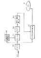
DVDレコーダにおいては、供給されたビデオ信号から、本発明によるウォータマークの検出方法に従ってウォータマークが検出される。DVDレコーダは、検出されたこのウォーターマークに応じて記録動作の禁止動作を制御する。図4は、かかるDVDレコーダの概略構成を示している。
【0029】
図4において、A/D変換器50は、上記第1または第2画像データを担うビデオ信号をディジタル化してディジタルビデオ信号を生成し、ブロック化回路51及び位置同定情報検出回路6Aに供給する。ブロック化回路51は、入力のディジタルビデオ信号を8×8画素データ毎の画素ブロックに分割し、これをDCT(discrete cosine transform)回路52に供給する。位置同定情報検出回路6Aは、入力のディジタルビデオ信号から第1のウォーターマークすなわち位置同定ウォーターマークを検出し、当該ウォーターマークに基づく単位ブロックのフレーム内位置情報をブロック化回路51に送出する。
【0030】
ブロック化回路51においては、かかるブロック分割に際して、上記位置同定ウォーターマークに基づいた単位画素ブロックの先頭位置確定をなす。つまり、位置同定ウォーターマークに基づいて適正なブロック認識を行いつつブロック分割を行う。その詳細は後述する。
DCT回路52は、かかるブロック化回路51によって決められた8×8画素データ単位の画素ブロック各々に対して2次元DCT演算を施すことにより64系統の周波数成分各々に対応したDCT係数DC1〜DC64を求め、これらを透かし情報検出回路60に送る。透かし情報検出回路60は、DCT係数DC1〜DC64から、同じく8×8画素データ単位の画素ブロック毎に上記コピー制御ウォーターマークを検出しそれを解読して当該ウォーターマークによって示される情報内容に応じた信号をビデオ信号記録系70へ供給する。
【0031】
ビデオ信号記録系70には、A/D変換器50のディジタル出力であるビデオ信号が供給されており、かかるビデオ信号に対して上記MPEG符号化器と同様の符号変換処理を施すとともに、記録可能なDVD8へ記録するための種々の信号処理を施して記録用ビデオ信号を生成し、これに応じたDVD8への記録をなす。ビデオ信号記録系70は、透かし情報検出回路60から供給されるウォーターマーク信号に応じて、当該ウォーターマークがDVD8へのコピーを禁止すべき旨を示していれば、記録動作を禁止する。他方、当該ウォーターマークがコピーの許可を示していれば、ビデオ信号記録系70は、記録動作を可能とする。
【0032】
次に、図3及び図4に示した構成に基づく位置同定ウォーターマークの埋め込み及び検出の原理につき詳述する。
[A]原理1(相関関数を利用した位置同定)
かかる原理は、相関関数を利用した位置同定に基づく。
いま、副透かし情報埋め込み回路10の入力画像すなわち原画像fに、当該埋め込み回路10において位置同定ウォーターマークとして独立したランダムノイズnを加え、これにより例えば逆DCT回路27の出力から得られる新たな画像をf′とする。つまり、f′=f+nの関係があるとする。
【0033】
この場合、f′とnとの相互相関関数Rf′,nは、次のようになる。
【0034】
【数1】

【0035】
ここで、原画像fとランダムノイズnは、互いに独立しているので、
【0036】
【数2】
Rf,n(t)=0 …(2)
となる。故に、
【0037】
【数3】
Rf′,n(t)=Rn(t) …(3)となる。
よって、ノイズの自己相関関数Rnが既知であれば、位置同定情報検出回路6Aにおいてそのマッチングをとることにより位置同定が可能となることが分かる。
【0038】
なお、Rn(t)とRf′,n(t)との関係を例示したものを図5に示す。
[B]原理2(M系列の使用)
より具体的には、上記ランダムノイズには、M系列を適用することができ、周期NのM系列の繰り返しを当該ノイズのランダムパターンとして使用することができる。
【0039】
ここで言うM系列とは、いわゆる最大長系列または最大周期列(Maximum length sequence)といわれる疑似不規則信号の1つである。M系列については、「M系列とその応用」(M−sequence and its applications)と題された文献(著作者:柏木 濶,1996年3月25日(株)昭晃堂より発行)に詳述されている。
【0040】
周期NのM系列akの“0”を−1、“1”を+1に対応させた系列mkの自己相関関数Rm(t)は、
【0041】
【数4】
【0042】
【数5】
=−1/N (t≠kN :kは整数) …(4)
が成立するという性質がある。M系列は、位置同定に有利な鋭い自己相関を持っている。上式からも分かるように、位置が一致したときにのみ鋭いピークを呈し、それ以外の場所では殆どゼロに近い値となる。このピークを検出することにより位置同定を行うことができる。
【0043】
かかる検出能力を上げるために、使用するM系列akは、周期Nとしてはなるべく長い方が良く、また、原画像との独立性が良いものが選択されることが好ましい。
なお、図6には、Rm(t)の特性図が示されている。
[C]埋め込み方法
次に、実際の位置同定ウォーターマーク埋め込み方法について説明する。
【0044】
先ず、位置同定ウォーターマークは、フレーム間で固定とし、M系列を基にし2次元に拡張したランダムパターンmx,yとする。また、使用するM系列akの周期Nには、1フレームの画素数より大きい値が選ばれる。さらに、ランダムパターン生成の基となるM系列akの生成は、原始多項式を利用したシフトレジスタにより行う。つまりROMとして持つ必要はない。またこの時のシフトレジスタの初期値は固定することにより、発生するランダムパターンをフレーム間で同じものとする。
【0045】
使用するランダムパターンmx,yは、発生されるM系列akの値により次式のように変化させる。当該式において、H,Vは、画像(フレーム画)の横方向,縦方向の画素数であり、Bは、強度のパラメータである。
【0046】
【数6】
mx,y=B (aHy+x=1)
または
【0047】
【数7】
=(−B+1)または(−B) (aHy+x=0) …(5)
このようにして生成されたランダムパターンmx,yは、原画像全体に加えられる。
この際、検出能力と画質を考慮に入れ、最適な強度Bを選ぶ。すなわち、強度Bは、画質・検出能力に多大な影響を及ぼすため、幾つかの値で埋め込みを試み、最適な値を求めるようにすると良い。
[D]検出方法
これに対して実際の位置同定ウォーターマークの検出方法は、次の如くである。
【0048】
ここで使用するM系列akを既知として使用し、次式の系列Ii,j(x,j)を得る。
【0049】
【数8】
I(i,j)x,y=1 (aH(y+j)+(x+i)=1)
または
【0050】
【数9】
=−1 (aH(y+j)+(x+i)=0) …(6)
;但し、原画像のサイズは横方向はH個の画素数、
縦方向はV個の画素数とする。
そしてこの系列Ii,j(x,j)と原画像fx,yとの相互相関を計算する。
【0051】
原画像と入力画像(ブロック化回路51及び位置同定情報検出回路6Aに供給されるウォーターマーク付きの画像)とのずれの範囲は既知である場合が多い。そこで、かかる範囲内で(i,j)を変化させ、上記計算処理すなわち系列Ii ,j(x,j)と原画像fx,yとの相互相関の計算を繰り返す。
かかる計算結果において相互相関のピーク値をとる時の(i,j)の組み合わせが、入力画像フレーム上における、原画像フレームの左上のピクセル(先頭単位画素ブロックの始端画素)に相当する位置を示すこととなる。
【0052】
このような手順を踏むことでアスペクト比変換後の画像データにおける最終的なブロックの位置同定が可能となる。この後得られた位置情報を基にコピー制御ウォーターマークの検出をブロック毎に行えば、適正な検出がなされることとなる。
図7は、図3に示される副透かし情報埋め込み回路10の主たる特徴的動作を示している。
【0053】
図7において、埋め込み回路10は、上記シフトレジスタの初期化を行い(ステップS01)、x,yのそれぞれに0を格納する(ステップS02)。
そして埋め込み回路10は、上記M系列akを求め(ステップS03)、上記ランダムパターンmx,yを求める(ステップS04)。さらに埋め込み回路10は、原画像fx,yにmx,yを加えて位置同定ウォーターマークの埋め込みを達成する(ステップS05)。そうして埋め込み回路10は、x,yの値を変更するとともに(ステップS06)、所定の画像領域についてのx,yの設定及びこれによるウォーターマークの埋め込みが終了するまで、ステップS03ないしS07の処理を繰り返す(ステップS07)。所定の画像領域についての当該処理が完了すると、埋め込み回路10は、次のフレーム画についての位置同定ウォーターマークの埋め込み処理を実行する。
【0054】
図8は、図4に示されるブロック化回路51,位置同定情報検出回路6A及び透かし情報検出回路60の主たる特徴的動作を示すフローチャートである。
図8において、A/D変換器50からディジタル化されたビデオ信号の入力があると(ステップS1)、ブロック化回路51は、コピー制御ウォーターマークが検出できたか否かを判別する(ステップS2)。この判別には、透かし情報検出回路60から発せられるコピー制御ウォーターマークの検出可否を示すフラグ信号(ウォーターマーク検出フラグ)が使われる。
【0055】
A/D変換器50からのビデオ信号が上記第1画像データを担うものであれば、多くの場合、当該ビデオ信号により形成されるフレーム画における単位画素ブロックの原画像に対する整合性は崩れていないので、ブロック化回路51において行われるブロック分割も所定の位置座標に基づいて行われ、これにより分割された各単位画素ブロックにつき透かし情報検出回路60はコピー制御ウォーターマークの適正な検出及び解読を行うことができる。(ウォーターマーク検出成功)
これに対して、A/D変換器50からのビデオ信号が上記第2画像データを担うものであれば、図2の(b),(c)において先述した如く当該ビデオ信号によって形成されるフレーム画における単位画素ブロックの原画像に対する整合性は崩れており、これに対処すべく位置同定情報検出回路6Aは、当該ビデオ信号がレターボックス形式なのか否かを判別する(ステップS3)。レターボックス形式でないと判断されたものは、パンスキャン形式であると判断することができる。
【0056】
レターボックス形式であれば、ブロック化回路51は、当該ビデオ信号をアップサンプリングして図2の(c)に示される変換方向とは逆のアスペクト変換をなして原画像に戻し(ステップS4)、パンスキャン形式であれば、当該ビデオ信号をダウンサンプリングして図2の(b)に示される変換方向とは逆のアスペクト変換をなして原画像に戻す(ステップS5)。
【0057】
こうして原画像に戻した後、位置同定情報検出回路6Aは、当該ビデオ信号に埋め込まれた位置同定ウォーターマークを用いて画像位置の同定、より詳しくは当該ビデオ信号に対して分割すべき単位画素ブロックの適正な位置決めを行う(ステップS6)。ここでの画像位置同定処理の詳細は、後述する。
かかる画像位置の同定後は、ブロック化回路51は、求められた単位画素ブロック位置に基づいて当該ビデオ信号のブロック分割を行い、透かし情報検出回路60は、この分割された各単位画素ブロックにつきコピー制御ウォーターマークの検出及び解読を行う(ステップS7)。適正なブロック分割がなされていれば、透かし情報検出回路60から出力される上記ウォーターマーク検出フラグがセット状態となり(ウォーターマーク検出成功)、ビデオ信号記録系70は、検出されるコピー制御ウォーターマークの内容に応じたDVD8への記録動作の禁止/許容をなす。これとは逆に、適正なブロック分割がなされていないなどして、透かし情報検出回路60から出力される上記ウォーターマーク検出フラグがセット状態とならない場合は(ウォーターマーク未検出)、ビデオ信号記録系70は、これに対応する処理、例えばDVD8への記録動作を禁止する。
【0058】
ウォーターマークが未検出となった場合は、さらに他の所定数フレームについて同様の処理が行われる。ここでもその所定数フレームからウォーターマークが検出できないときは、最終的なウォーターマーク検出不成功の判断を下す。
ステップS3の処理の手順は、図9に示される。
図9において、位置同定情報検出回路6Aは、先ずスレッショルドthの値を設定する(ステップS31)。そして位置同定情報検出回路6Aは、このスレッショルドthの値に基づいて入力ビデオ信号を2値化する(ステップS32)。
【0059】
2値化されたデータは、位置同定情報検出回路6Aにより所定画像領域すなわちフレーム画の上下部分に値ゼロの帯状画像があるか否かが判別される(ステップS33)。かかる帯状画像は、図2の(c)に示されるレターボックス画像に特有のものであり、原画像の上下に付けられた画像に相当する。
したがって、この帯状画像があれば当該ビデオ信号がレターボックス画像を担うものと判別することができ、なければ当該ビデオ信号がパンスキャン画像を担うものと判別することができるのである。
【0060】
図8に示されるステップS6の処理の手順は、図10に示される。
図10において、位置同定情報検出回路6Aは、先ずi,jを初期化すべくそれぞれに0を格納し(ステップS61)、x,y,Sにもそれぞれ0を格納する(ステップS62)。
次いで位置同定情報検出回路6Aは、M系列akを求め(ステップS63)、上記(6)式に基づいてランダムパターンI(i,j)x,yを求める(ステップS64)。位置同定情報検出回路6Aは、この求めた系列I(i,j)x,yと原画像fx,yとの積を計算してその計算結果をSに加える(ステップS65)。そうして位置同定情報検出回路6Aは、x,yを変更し(ステップS66)、所定の画像領域についての計算が終了するまで、これらステップS63ないしS66の処理を繰り返す(ステップS67)。
【0061】
所定画像領域についての積和計算が終了すると、相関係数が確定する。位置同定情報検出回路6Aは、確定した相互相関Ri,jとしてSの値を置き換える(ステップS68)。そしてブロック化回路51は、i,jを変更し(ステップS69)、所定の探索領域についてi,jの設定及びこれによる計算が終了するまで、ステップS62ないしS69の処理を繰り返す(ステップS6A)。
【0062】
所定探索領域についてのi,jの計算処理が終了すると、位置同定情報検出回路6Aは、ステップS68において格納した相互相関Ri,jの値のうちの最大値を検知するとともに、検知されたその最大値に対応する(i,j)が同定された位置を指すものとして認識する(ステップS6B)。認識後は、このフローチャートの処理を終了する。
【0063】
かくして位置同定情報検出回路6Aは、パンスキャン画像のデータが入力された場合に、図2(b)に示される如き当該4:3の画像の左から3番目の単位画素ブロックが欠けていることを認識することができ、欠けていない次の単位画素ブロックから正しくコピー制御ウォーターマークの検出を開始させることができる。これにより、当該3番目の単位画素ブロック以降の単位画素ブロックについてもウォーターマークの適正な検出を行わせるができ、従来のような不具合を生じない。
【0064】
また、レターボックス画像のデータが入力された場合にも、図2(c)に示される如き当該4:3の画像データの当該先頭単位画素ブロックが画像(フレーム画)において一番左から当該移動位置に変わったことを認識することができ、その移動位置から正しくコピー制御ウォーターマークの検出を開始することができる。これにより、当該移動位置以降の単位画素ブロックについてウォーターマークの適正な検出ができ、従来のような不具合を生じない。
【0065】
なお、上記実施例においては、DVDレコーダにおいてなされる位置同定につき説明したが、本発明は、この形態に必ずしも限定されることはない。例えばインターネット他、種々の媒体を扱う通信ないしは伝送形態において送受される情報データ信号に対して位置同定を行うことができる。
また、上記実施例においては、主たる第1のウォーターマークとしてコピーを許容するか否かの情報を担うコピー制御ウォーターマークにつき説明したが、本発明は、これに必ずしも限定されることもない。例えば当該著作物の使用を許可された者のID情報を第1のウォーターマークの情報としても良いし、他にも種々様々な情報を適用することができる。
さらに上記実施例においては、DCT及び逆DCTを使ったウォーターマークの埋め込みについて説明したが、先述した如き標本値に透かし情報を埋め込む方式においてもブロック分割法は適用可能であり、かかるブロック分割に際しても本発明は有効である。要するに、透かしを入れるべき情報データをブロック分割して主たるウォーターマークを埋め込む形態に、本発明は広く適用可能なのである。
【0066】
また、上記実施例においては、画像データについての透かし情報埋め込み及び検出について説明したが、音声データ等に対しても本発明を適用可能であることは勿論である。
また、上記実施例においては、画像データ信号の分割単位ブロックとして、8×8画素のデータを挙げたが、これ以外の単位ブロックを形成しても良いことは勿論である。
【0067】
この他にも、上記実施例においては種々の手段を限定的に説明したが、当業者の設計可能な範囲にて適宜改変することも可能である。
【0068】
【発明の効果】
以上詳述したように、本発明によれば、ブロック分割法において適正に単位情報ブロックを認識し、確実に透かし情報を検出することのできる電子透かし重畳方法及び検出方法並びに装置を提供することができる。
また、画素データにアスペクト比変換を施した後も、適正に単位画素ブロックを認識して確実に透かし情報を検出することができる。
【図面の簡単な説明】
【図1】ブロック分割法によって電子透かし情報が画像データに埋め込まれる態様を示す摸式図である。
【図2】DVDに記録されたスクイーズ形式画像からの各種アスペクト比変換の態様を示す摸式図である。
【図3】本発明による一実施例のウォータマーク重畳装置の概略構成を示すブロック図である。
【図4】本発明による一実施例のウォーターマーク検出装置が採用されたDVDレコーダの概略構成を示すブロック図である。
【図5】透かし情報の埋め込まれた画像f′とランダムノイズnの相互相関関数Rf′,n(t)とランダムノイズnの自己相関関数Rn(t)との関係を例示するタイムチャートである。
【図6】周期NのM系列akの“0”を−1、“1”を+1に対応させた系列mkの自己相関関数Rm(t)の特性図である。
【図7】図3に示される装置においてなされる位置同定ウォーターマークの埋め込み動作を示すフローチャートである。
【図8】図4に示されるブロック化回路と透かし情報検出回路とにおいてなされる特徴的動作を示すフローチャートである。
【図9】図8に示されるステップS3のレターボックス判定処理の手順を示すフローチャートである。
【図10】図8に示されるステップS6の位置同定処理の手順を示すフローチャートである。
【符号の説明】
12 ブロック化回路
13 DCT回路
10 副透かし情報埋め込み回路
20 主透かし情報埋め込み回路
27 逆DCT回路
29 フォーマット変換回路
50 A/D変換器
51 ブロック化回路
52 DCT回路
60 透かし情報検出回路
6A 位置同定情報検出回路
70 ビデオ信号記録系
8 書き込み可能型DVD[0001]
BACKGROUND OF THE INVENTION
The present invention relates to a technique for superimposing or embedding digital watermark information (hereinafter referred to as a watermark) in image or audio data so as to conceal it, and in particular, information in units of blocks each consisting of a small number of pieces of information data pieces. The present invention relates to a method for embedding a watermark in a data signal, a method for detecting the watermark from the embedded information data signal, and an apparatus according to these methods.
[0002]
[Prior art]
Currently, DVD-R or DVD-RAM is being put into practical use as an optical recording medium on which information data can be written. Video, audio software, etc., are being put into practical use for DVD-RAM or DVD-R. It is necessary to take measures to prevent illegal copying. In view of this, attention has been paid to a digital watermark technique in which copyright information and information indicating copy guard are represented by a watermark, which is an image pattern that is visually or auditorily inconspicuous, and the watermark is superimposed on image data or audio data. .
[0003]
The basic scheme of such digital watermark technology is roughly divided into two. One is a method of embedding a watermark by processing a sample value such as a waveform or a pixel. For example, a method of adding a watermark to a luminance value of an image corresponds to this. The other is a method of converting image data and audio data into frequency components and embedding a watermark in a specific frequency component. For such frequency conversion, FFT (Fast Fourier Transform), DCT (Discrete Cosine Transform) or the like is used.
[0004]
On the other hand, in another aspect, there is a technique for embedding watermark information by dividing data into a plurality of small pixel blocks (hereinafter referred to as a block division method) (see FIG. 1). In this technique, image data is divided into a plurality of small unit pixel blocks each having an N × N pixel size, and watermarks having the same block size as the unit pixel blocks are added together. According to this, even if a part of one frame of image data is cut out, the watermark remains unless the size is smaller than the unit pixel block. On the reproduction side, the embedded data is divided into similar unit pixel blocks, and a watermark is detected and decoded for each unit pixel block.
[0005]
Here, consider a form in which, for example, image data in which a watermark is embedded is recorded on a disc such as a DVD, and the image data is read and reproduced from the disc.
A disc player that reads such a disc has a first image signal having an aspect ratio (aspect ratio) of 16: 9 for displaying an image on a so-called wide television, and 4: for displaying an image on a normal television. It may be required to output a second image signal having an aspect ratio of 3 images. Assuming that DVD has recorded therein image data for forming an original image of 480 [dots] × 720 [dots] in a squeeze format, this disc player has an aspect ratio for image data obtained from a DVD. Conversion must be performed to generate the first image signal. The same applies to the second image signal, and the second image signal must be generated by subjecting the image data obtained from the DVD to aspect ratio conversion.
[0006]
The aspect ratio conversion into the first image signal can basically be achieved as shown in FIG. 2A by performing pixel interpolation in the horizontal direction of the screen. The aspect ratio conversion into the second image signal may be in two forms as shown in FIGS. 2B and 2C.
As shown in FIG. 2B, the squeeze format original image of 480 [dots] × 720 [dots] recorded on the DVD is up-sampled so that the aspect ratio is 4: 3. Is converted. This is a so-called pan-scan converted image, and takes a form in which left and right end portions of an image based on image data obtained from a DVD are cut out so as to be an image having an aspect ratio of 4: 3. Also, as shown in FIG. 2C, the original image recorded on the DVD is down-sampled and converted to image data so as to have an aspect ratio of 4: 3. This is a so-called letterbox conversion image, and a predetermined image (for example, a black-colored belt-like image) is pasted on the upper and lower end portions of the image data obtained from the DVD so that the image has an aspect ratio of 4: 3. Take the attached form.
[0007]
The second image signal converted into the pan-scan and letterbox image can be recorded on a recording medium such as the DVD-R or DVD-RAM in a DVD recorder, for example, in the same manner as the first image signal. At this time, the DVD recorder detects and decodes the watermark embedded in the second image signal in order to prevent copyright infringement. For example, when it is detected that the watermark carries information indicating that copying is prohibited, the DVD recorder prohibits its own recording operation, and even if a recordable DVD is supplied, the second image signal is output to this. Do not record. On the other hand, the DVD recorder can record the second image signal on the supplied DVD only when it is detected that the watermark bears information indicating permission of copying.
[0008]
In the case of (a), the DVD player uses all the information of the squeeze format original image and converts the information to 16: 9 image information in a stretched form. The upper left unit pixel block is similarly positioned at the upper left in the 16: 9 image after conversion. Therefore, the DVD recorder can appropriately detect and decode the watermark sequentially from, for example, the upper left unit pixel block of the supplied 16: 9 image data.
[0009]
However, as can be seen from FIGS. 2B and 2C, images such as pan scan and letterbox have their pixel positions and sizes changed from the original image. It is necessary to make the block recognition different from the case of (a).
More specifically, in the case of (b), the DVD player converts the information on the left side and the right side of the squeeze format original image and converts the remaining information into 4: 3 image information in a form that stretches the remaining information. Therefore, in the block division method, the upper left unit pixel block in the original image is already lost in the 4: 3 image after conversion. Further, as shown in the figure, for example, even if the third unit pixel block from the left in the top row is present in the 4: 3 image after conversion, the 4: 3 image may start from the middle of the block. High nature.
[0010]
In such a case, when the DVD recorder starts detection of the watermark without recognizing that the supplied unit image block of 4: 3, for example, the third unit pixel block from the left is missing, As a result, the watermark cannot be detected properly not only in the unit pixel block but also in the subsequent unit pixel blocks.
[0011]
In the case of (c), the DVD player synthesizes a predetermined image on the upper and lower sides of the squeeze format original image, and converts the combined image information into 4: 3 image information in a stretched form. In the block division method, the uppermost first unit pixel block in the original image does not correspond to the uppermost left of the 4: 3 image after conversion, and is in the column immediately below the upper predetermined image used for the composition. It will be moved to the leftmost position.
[0012]
In such a case, the DVD recorder does not recognize that the head unit pixel block of the supplied 4: 3 image data has changed from the leftmost to the movement position in the image (frame image), and the watermark When detection is started, the watermark cannot be detected from a predetermined image in which the watermark is not embedded, and this state continues for a long time. Depending on the watermark detection process, if the watermark undetected state continues for a long time, an error may be output, or the watermark may be treated as not existing in the image.
[0013]
[Problems to be solved by the invention]
The present invention has been made in view of the above-described problems, and an object of the present invention is to provide a digital watermark superimposing method capable of properly recognizing a unit information block in the block division method and reliably detecting watermark information. And a detection method and apparatus.
[0014]
Another object of the present invention is to provide a digital watermark superimposing method and detection method for image data that can properly detect a unit pixel block and reliably detect watermark information even after the aspect ratio conversion is performed on the pixel data. And providing an apparatus.
[0015]
[Means for Solving the Problems]
The digital watermark superimposing method according to the present invention includes:originalInformation day to carry informationToA method for superimposing digital watermark information, comprising:1The modified information data obtained by embedding digital watermark informationMultipleDivide into unit blocksSteps to doThe concernedunitblockGenerating a plurality of frequency components by performing two-dimensional frequency conversion on each of the frequency components,Second2Embedded watermark informationEach of the modified frequency components obtained thereby is subjected to inverse transformation of the two-dimensional frequency transformation to generate a plurality of modified unit blocks;,Re-synthesize the plurality of modified unit blocks to generate output data, andSaid1The watermark information ofOutput dataIn a given section ofOf the modified unit blockIt is characterized by carrying information for identifying the position.
[0016]
In such a method, the information dataTCan be a video signal.
The digital watermark superimposing device according to the present invention is:originalInformation day to carry informationToAn apparatus for superimposing digital watermark information, wherein the information data1Sub-embedding means for embedding the electronic watermark information of, and the modified information data obtained by the sub-embedding meansMultipleBlocking means for dividing into unit blocks, andunitblockConversion means for performing two-dimensional frequency conversion on each of the two to generate a plurality of frequency components, and the frequency componentsSecond2Embedded watermark informationBy this, the modified frequency component is obtainedMain embedding means and, Inverse transforming means for generating a plurality of modified unit blocks by performing inverse transformation of the two-dimensional frequency transform on each of the modified frequency components, and recombining for recombining the plurality of modified unit blocks to generate output data Means,Said first1The watermark information ofOutput dataIn a given section ofOf the modified unit blockIt is characterized by carrying information for identifying the position.
[0017]
In such a device, the information dataTCan be a video signal.
The first1This digital watermark information can be random pattern information generated based on the M sequence.
A digital watermark detection method according to the present invention includes:pluralUnit blockInput consisting ofInformation dayFromAn electronic watermark detection method for detecting electronic watermark information, comprising:inputInformation dayTakaEtEmbedded in the input information dataFirst1Detect digital watermark information of the1Based on digital watermark information,in frontRecordinputInformation dayOfIn a given sectionOf the unit blockRecognizing the position, and based on the recognized positioninputInformation dayMultipleDivide into unit blocksSteps to do,SaidUnit blockGenerating a plurality of frequency components by performing two-dimensional frequency conversion on each of the components, and embedding the frequency components into the frequency componentsFirst2Detect digital watermark informationStep and,HaveIt is characterized by that.
[0018]
In such a method,inputInformation dayTCan be a video signal.
An electronic watermark detection apparatus according to the present invention includes:pluralUnit blockInput consisting ofInformation dayFrom the aboveAn electronic watermark detection apparatus for detecting electronic watermark information, comprising:inputInformation dayTakaEtEmbedded in the input information dataFirst1Detect digital watermark information of the1Based on digital watermark information,in frontRecordinputInformation dayOfIn a given sectionOf the unit blockPosition identification information detecting means for recognizing the position, and based on the recognition positioninputInformation dayMultipleBlocking means for dividing into unit blocks;in frontUnit blocks divided by the blocking meansTransform means for generating a plurality of frequency components by performing two-dimensional frequency transform on each, and embedded in the frequency component from the frequency componentFirst2And watermark information detecting means for detecting the digital watermark information.
[0019]
In such an apparatus,inputInformation dayTCan be a video signal.
The video signal can bear a letterbox image or a pan-scan image.
Furthermore, in each aspect of the digital watermark detection apparatus, the position identification information detection means is generated based on an M sequence.Two dimensionsRandom pattern informationIs detected as the first digital watermark information, and information on the detected two-dimensional random pattern is detected.Based on the aboveinputInformation dataRecognize the position of the unit block in a predetermined section ofTo be able to.
[0020]
DETAILED DESCRIPTION OF THE INVENTION
Hereinafter, embodiments of the present invention will be described in detail with reference to the drawings.
FIG. 3 shows a schematic configuration of a watermark superimposing apparatus that generates a watermark according to the watermark superimposing method of the present invention and superimposes it on an input video signal.
[0021]
In FIG. 3, an input video signal which is a sample value series digital signal is supplied to a sub-watermark
[0022]
The blocking
[0023]
The embedding
[0024]
The embedding
[0025]
In this way, the 64 DCT coefficients in which the watermark is embedded are supplied to the
[0026]
A
The output video signal is subjected to predetermined encoding by an unillustrated MPEG (Moving Picture Experts Group) encoder, and after being subjected to various signal processing, is recorded on the DVD.
[0027]
The DVD recorded as described above is read by a DVD player (not shown). Such a DVD player demodulates and decodes the read signal of the DVD, and converts the aspect ratio of the decoded output video signal as described in the prior art (FIGS. 2A, 2B, and 2C). To obtain the first or second image data in the wide TV, pan scan or letterbox format as described above, and output it as an analog video signal.
[0028]
Such an analog video signal is supplied to a DVD recorder and becomes a signal to be recorded on a disc such as a DVD-RAM or a DVD-R in the DVD recorder.
In the DVD recorder, the watermark is detected from the supplied video signal according to the watermark detection method of the present invention. The DVD recorder controls the prohibition operation of the recording operation in accordance with the detected watermark. FIG. 4 shows a schematic configuration of such a DVD recorder.
[0029]
In FIG. 4, the A /
[0030]
In the
The
[0031]
The video
[0032]
Next, the principle of embedding and detecting the position identification watermark based on the configuration shown in FIGS. 3 and 4 will be described in detail.
[A] Principle 1 (position identification using correlation function)
Such a principle is based on position identification using a correlation function.
Now, random noise n independent as a position identification watermark in the embedding
[0033]
In this case, the cross-correlation function R between f ′ and nf′,nIs as follows.
[0034]
[Expression 1]
[0035]
Here, since the original image f and the random noise n are independent of each other,
[0036]
[Expression 2]
Rf, n(T) = 0 (2)
It becomes. Therefore,
[0037]
[Equation 3]
Rf′, N(T) = Rn(T) (3)
Thus, the noise autocorrelation function RnIs known, the position identification
[0038]
Rn(T) and Rf′, NAn example of the relationship with (t) is shown in FIG.
[B] Principle 2 (use of M series)
More specifically, an M sequence can be applied to the random noise, and a repetition of the M sequence with a period N can be used as a random pattern of the noise.
[0039]
The M sequence referred to here is one of pseudo-random signals called a so-called maximum length sequence or maximum period sequence (Maximum length sequence). The M series is described in detail in a document entitled “M-sequence and its applications” (authored by Satoshi Kashiwagi, published on March 25, 1996 by Shogodo Co., Ltd.). Has been.
[0040]
M series a with period NkA sequence m in which “0” is associated with −1 and “1” with +1kThe autocorrelation function Rm (t) of
[0041]
[Expression 4]
[0042]
[Equation 5]
= -1 / N (t ≠ kN: k is an integer) (4)
Is true. The M sequence has a sharp autocorrelation advantageous for position identification. As can be seen from the above equation, a sharp peak is exhibited only when the positions coincide with each other, and the value is almost zero at other locations. The position can be identified by detecting this peak.
[0043]
In order to increase the detection capability, the M sequence a usedkThe period N is preferably as long as possible, and it is preferable to select one having good independence from the original image.
FIG. 6 is a characteristic diagram of Rm (t).
[C] Embedding method
Next, an actual position identification watermark embedding method will be described.
[0044]
First, the position identification watermark is fixed between frames, and is a random pattern m that is two-dimensionally expanded based on the M series.x, yAnd Also, M series a to be usedkA value larger than the number of pixels in one frame is selected for the period N of. Further, an M sequence a that is a basis for generating a random patternkIs generated by a shift register using a primitive polynomial. That is, it is not necessary to have it as a ROM. Further, by fixing the initial value of the shift register at this time, the generated random pattern is made the same between frames.
[0045]
Random pattern m to usex, yIs the generated M sequence akThe value is changed as shown in the following equation. In this equation, H and V are the numbers of pixels in the horizontal and vertical directions of the image (frame image), and B is an intensity parameter.
[0046]
[Formula 6]
mx, y= B (aHy + x= 1)
Or
[0047]
[Expression 7]
= (-B + 1) or (-B) (aHy + x= 0) ... (5)
Random pattern m generated in this wayx, yIs added to the entire original image.
At this time, the optimum intensity B is selected in consideration of the detection capability and the image quality. That is, since the intensity B has a great influence on the image quality / detection capability, it is preferable to try embedding with several values and obtain an optimum value.
[D] Detection method
On the other hand, the actual method for detecting the position identification watermark is as follows.
[0048]
M series a used herekAs known and the series Ii, j (x, j)Get.
[0049]
[Equation 8]
I(I, j) x, y= 1 (aH (y + j) + (x + i)= 1)
Or
[0050]
[Equation 9]
= -1 (aH (y + j) + (x + i)= 0) (6)
However, the size of the original image is H pixels in the horizontal direction,
The vertical direction is the number of V pixels.
And this series Ii, j (x, j)And the original image fx, yAnd calculate the cross correlation.
[0051]
The range of deviation between the original image and the input image (an image with a watermark supplied to the blocking
In this calculation result, the combination of (i, j) when taking the peak value of the cross-correlation indicates the position corresponding to the upper left pixel of the original image frame (starting end pixel of the first unit pixel block) on the input image frame. It will be.
[0052]
By following such a procedure, it is possible to finally identify the position of the block in the image data after the aspect ratio conversion. If the copy control watermark is detected for each block based on the position information obtained thereafter, proper detection is performed.
FIG. 7 shows the main characteristic operation of the sub-watermark
[0053]
In FIG. 7, the embedding
Then, the embedding
[0054]
FIG. 8 is a flowchart showing main characteristic operations of the blocking
In FIG. 8, when a digitized video signal is input from the A / D converter 50 (step S1), the blocking
[0055]
If the video signal from the A /
On the other hand, if the video signal from the A /
[0056]
If the letterbox format is used, the blocking
[0057]
After returning to the original image in this way, the position identification
After the image position is identified, the blocking
[0058]
When the watermark is not detected, the same processing is performed for another predetermined number of frames. Here again, when the watermark cannot be detected from the predetermined number of frames, a final determination of unsuccessful watermark detection is made.
The processing procedure of step S3 is shown in FIG.
In FIG. 9, the position identification
[0059]
In the binarized data, it is determined by the position identification
Therefore, if the strip image is present, it can be determined that the video signal bears a letterbox image, and if not, it can be determined that the video signal bears a pan-scan image.
[0060]
The procedure of the process in step S6 shown in FIG. 8 is shown in FIG.
In FIG. 10, the position identification
Next, the position identification
[0061]
When the product-sum calculation for the predetermined image area is completed, the correlation coefficient is determined. The position identification
[0062]
When the calculation processing of i and j for the predetermined search region is completed, the position identification
[0063]
Thus, when the pan scan image data is input, the position identification
[0064]
Also, when letterbox image data is input, the head unit pixel block of the 4: 3 image data as shown in FIG. 2C is moved from the leftmost in the image (frame image). It can be recognized that the position has been changed, and the detection of the copy control watermark can be started correctly from the movement position. As a result, the watermark can be properly detected for the unit pixel blocks after the movement position, and the conventional problems do not occur.
[0065]
In the above embodiment, the position identification performed in the DVD recorder has been described. However, the present invention is not necessarily limited to this form. For example, position identification can be performed on information data signals transmitted and received in communication or transmission forms that handle various media such as the Internet.
In the above-described embodiment, the copy control watermark that bears information as to whether or not copying is permitted as the main first watermark has been described. However, the present invention is not necessarily limited to this. For example, ID information of a person who is permitted to use the copyrighted work may be used as the first watermark information, and various other information may be applied.
Furthermore, in the above embodiment, watermark embedding using DCT and inverse DCT has been described. However, the block division method can also be applied to a method of embedding watermark information in a sample value as described above. The present invention is effective. In short, the present invention can be widely applied to a mode in which the main watermark is embedded by dividing the information data to be watermarked into blocks.
[0066]
In the above embodiment, watermark information embedding and detection for image data have been described. However, the present invention is naturally applicable to audio data and the like.
In the above embodiment, 8 × 8 pixel data is used as the divided unit block of the image data signal. However, other unit blocks may be formed as a matter of course.
[0067]
In addition to the above, various means have been described in a limited manner in the above embodiment, but can be appropriately modified within a range that can be designed by those skilled in the art.
[0068]
【The invention's effect】
As described above in detail, according to the present invention, it is possible to provide a digital watermark superimposing method, a detecting method, and an apparatus capable of properly recognizing a unit information block in the block division method and reliably detecting watermark information. it can.
Even after the aspect ratio conversion is performed on the pixel data, the unit pixel block can be properly recognized and the watermark information can be reliably detected.
[Brief description of the drawings]
FIG. 1 is a schematic diagram showing a mode in which digital watermark information is embedded in image data by a block division method.
FIG. 2 is a schematic diagram showing various aspect ratio conversion modes from a squeeze format image recorded on a DVD.
FIG. 3 is a block diagram showing a schematic configuration of a watermark superimposing apparatus according to an embodiment of the present invention.
FIG. 4 is a block diagram showing a schematic configuration of a DVD recorder in which the watermark detection device of one embodiment according to the present invention is employed.
FIG. 5 is a cross-correlation function R between an image f ′ in which watermark information is embedded and random noise n.f′,n(T) and autocorrelation function R of random noise nnIt is a time chart which illustrates the relationship with (t).
FIG. 6: M sequence a with period NkA sequence m in which “0” is associated with −1 and “1” with +1kFIG. 6 is a characteristic diagram of the autocorrelation function Rm (t).
7 is a flowchart showing a position identification watermark embedding operation performed in the apparatus shown in FIG. 3; FIG.
FIG. 8 is a flowchart showing characteristic operations performed in the blocking circuit and the watermark information detection circuit shown in FIG. 4;
FIG. 9 is a flowchart showing a procedure of letterbox determination processing in step S3 shown in FIG.
FIG. 10 is a flowchart showing the procedure of position identification processing in step S6 shown in FIG.
[Explanation of symbols]
12 Block circuit
13 DCT circuit
10 Sub-watermark information embedding circuit
20 Main watermark information embedding circuit
27 Inverse DCT circuit
29 Format conversion circuit
50 A / D converter
51 Blocked circuit
52 DCT circuit
60 Watermark information detection circuit
6A Position identification information detection circuit
70 Video signal recording system
8 Writable DVD
Claims (14)
前記情報データに第1の電子透かし情報を埋め込み、これにより得られる改変情報データを複数の単位ブロックに分割するステップと、
当該単位ブロックの各々に2次元周波数変換を施して複数の周波数成分を生成するステップと、
前記周波数成分に第2の電子透かし情報を埋め込み、これにより得られる改変周波数成分の各々に前記2次元周波数変換の逆変換を施して複数の改変単位ブロックを生成するステップと、
前記複数の改変単位ブロックを再合成して出力データを生成するステップと、からなり、
前記第1の電子透かし情報は、前記出力データの所定区間における前記改変単位ブロックの位置を同定するための情報を担う、ことを特徴とする電子透かし重畳方法。 To information data responsible for the original information there is provided a method of superimposing the electronic watermark information,
A step of said information data into the embedded first watermark information, divides the modified information data obtained thereby to a plurality of unit blocks,
Performing two-dimensional frequency conversion on each of the unit blocks to generate a plurality of frequency components;
Generating a plurality of modified unit blocks the second embeds digital watermark information by performing inverse transformation of the two-dimensional frequency conversion thereby into respective modifications frequency component obtained in the frequency component,
Re-synthesize the plurality of modified unit blocks to generate output data, and
The digital watermark superimposing method, wherein the first digital watermark information carries information for identifying a position of the modification unit block in a predetermined section of the output data .
前記情報データに第1の電子透かし情報を埋め込む副埋め込み手段と、
前記副埋め込み手段により得られる改変情報データを複数の単位ブロックに分割するブロック化手段と、
当該単位ブロックの各々に2次元周波数変換を施して複数の周波数成分を生成する変換手段と、
前記周波数成分に第2の電子透かし情報を埋め込み、これにより改変周波数成分を得る主埋め込み手段と、
前記改変周波数成分の各々に前記2次元周波数変換の逆変換を施して複数の改変単位ブロックを生成する逆変換手段と、
前記複数の改変単位ブロックを再合成して出力データを生成する再合成手段と、
を有し、
前記第1の電子透かし情報は、前記出力データの所定区間における前記改変単位ブロックの位置を同定するための情報を担う、ことを特徴とする電子透かし重畳装置。An apparatus for superimposing digital watermark information to the information data carrying the original information,
Sub-embedding means for embedding first digital watermark information in the information data;
And blocking means for dividing the modified information data obtained by the sub embedding unit into a plurality of unit blocks,
Conversion means for performing two-dimensional frequency conversion on each of the unit blocks to generate a plurality of frequency components;
Embeds a second electronic watermark information on said frequency component, a main embedding means for obtaining this by modifying the frequency components,
Inverse transformation means for producing a plurality of modified unit blocks by performing inverse transformation of the two-dimensional frequency transformation on each of the modified frequency components;
Re-synthesizing means for re-synthesizing the plurality of modified unit blocks to generate output data;
Have
The digital watermark superimposing apparatus, wherein the first digital watermark information carries information for identifying a position of the modification unit block in a predetermined section of the output data .
前記入力情報データから当該入力情報データに埋め込まれた第1の電子透かし情報を検出し、当該第1の電子透かし情報に基づいて、前記入力情報データの所定区間における前記単位ブロックの位置を認識し、当該認識位置に基づいて前記入力情報データを複数の単位ブロックに分割するステップと、
前記単位ブロックの各々に2次元周波数変換を施して複数の周波数成分を生成するステップと、
前記周波数成分から当該周波数成分に埋め込まれた第2の電子透かし情報を検出するステップと、
を有することを特徴とする電子透かし検出方法。An electronic watermark detecting method for detecting digital watermark information from the input information data composed of a plurality of unit blocks,
Detecting a first digital watermark information embedded in the input information data or al the input information data, based on the first electronic watermark information, the unit block before Symbol input information data in the predetermined section position recognize, dividing the input information data into a plurality of unit blocks based on the recognized position,
Generating a plurality of frequency components by performing two-dimensional frequency transform on each of said unit blocks,
Detecting a second digital watermark information embedded in the frequency component from the frequency component,
Digital watermark detection method characterized by having a.
前記入力情報データから当該入力情報データに埋め込まれた第1の電子透かし情報を検出し、当該第1の電子透かし情報に基づいて、前記入力情報データの所定区間における前記単位ブロックの位置を認識する位置同定情報検出手段と、
当該認識位置に基づいて前記入力情報データを複数の単位ブロックに分割するブロック化手段と、
前記ブロック化手段により分割された単位ブロック各々に2次元周波数変換を施して複数の周波数成分を生成する変換手段と、
前記周波数成分から当該周波数成分に埋め込まれた第2の電子透かし情報を検出する透かし情報検出手段と、
を有することを特徴とする電子透かし検出装置。An electronic watermark detection apparatus for detecting the electronic watermark information from the input information data composed of a plurality of unit blocks,
Detecting a first digital watermark information embedded in the input information data or al the input information data, based on the first electronic watermark information, the unit block before Symbol input information data in the predetermined section Position identification information detecting means for recognizing the position;
And blocking means for dividing the input information data into a plurality of unit blocks based on the recognized position,
Conversion means for generating a plurality of frequency components by performing two-dimensional frequency conversion unit blocks each divided by prior Symbol blocking means,
Watermark information detecting means for detecting second digital watermark information embedded in the frequency component from the frequency component ;
A digital watermark detection apparatus comprising:
Priority Applications (4)
| Application Number | Priority Date | Filing Date | Title |
|---|---|---|---|
| JP29312397A JP4064506B2 (en) | 1997-09-17 | 1997-09-17 | Digital watermark superimposing method, detecting method and apparatus |
| US09/152,293 US6246775B1 (en) | 1997-09-17 | 1998-09-14 | Method and appartus for superposing a digital watermark and method and apparatus for detecting a digital watermark |
| EP19980307417 EP0903943A3 (en) | 1997-09-17 | 1998-09-14 | Method and apparatus for superposing a digital watermark and method and apparatus for detecting a digital watermark |
| US09/829,206 US6389152B2 (en) | 1997-09-17 | 2001-04-09 | Method and apparatus for superposing a digital watermark and method and apparatus for detecting a digital watermark |
Applications Claiming Priority (1)
| Application Number | Priority Date | Filing Date | Title |
|---|---|---|---|
| JP29312397A JP4064506B2 (en) | 1997-09-17 | 1997-09-17 | Digital watermark superimposing method, detecting method and apparatus |
Related Child Applications (1)
| Application Number | Title | Priority Date | Filing Date |
|---|---|---|---|
| JP2004269914A Division JP4098293B2 (en) | 2004-09-16 | 2004-09-16 | Digital watermark superimposing method, detecting method and apparatus |
Publications (2)
| Publication Number | Publication Date |
|---|---|
| JPH1198479A JPH1198479A (en) | 1999-04-09 |
| JP4064506B2 true JP4064506B2 (en) | 2008-03-19 |
Family
ID=17790727
Family Applications (1)
| Application Number | Title | Priority Date | Filing Date |
|---|---|---|---|
| JP29312397A Expired - Fee Related JP4064506B2 (en) | 1997-09-17 | 1997-09-17 | Digital watermark superimposing method, detecting method and apparatus |
Country Status (3)
| Country | Link |
|---|---|
| US (2) | US6246775B1 (en) |
| EP (1) | EP0903943A3 (en) |
| JP (1) | JP4064506B2 (en) |
Families Citing this family (138)
| Publication number | Priority date | Publication date | Assignee | Title |
|---|---|---|---|---|
| US6636615B1 (en) | 1998-01-20 | 2003-10-21 | Digimarc Corporation | Methods and systems using multiple watermarks |
| US6721440B2 (en) | 1995-05-08 | 2004-04-13 | Digimarc Corporation | Low visibility watermarks using an out-of-phase color |
| US6728390B2 (en) * | 1995-05-08 | 2004-04-27 | Digimarc Corporation | Methods and systems using multiple watermarks |
| US6763123B2 (en) | 1995-05-08 | 2004-07-13 | Digimarc Corporation | Detection of out-of-phase low visibility watermarks |
| US7054462B2 (en) | 1995-05-08 | 2006-05-30 | Digimarc Corporation | Inferring object status based on detected watermark data |
| US6718046B2 (en) | 1995-05-08 | 2004-04-06 | Digimarc Corporation | Low visibility watermark using time decay fluorescence |
| US20030056103A1 (en) | 2000-12-18 | 2003-03-20 | Levy Kenneth L. | Audio/video commerce application architectural framework |
| US6427012B1 (en) * | 1997-05-19 | 2002-07-30 | Verance Corporation | Apparatus and method for embedding and extracting information in analog signals using replica modulation |
| US6804376B2 (en) | 1998-01-20 | 2004-10-12 | Digimarc Corporation | Equipment employing watermark-based authentication function |
| JP4313873B2 (en) | 1998-01-30 | 2009-08-12 | キヤノン株式会社 | Electronic device and data processing method |
| US6971011B1 (en) * | 1998-03-04 | 2005-11-29 | Koninklijke Philips Electronics N.V. | Watermark detection |
| US7602940B2 (en) * | 1998-04-16 | 2009-10-13 | Digimarc Corporation | Steganographic data hiding using a device clock |
| US7644282B2 (en) | 1998-05-28 | 2010-01-05 | Verance Corporation | Pre-processed information embedding system |
| US6154571A (en) * | 1998-06-24 | 2000-11-28 | Nec Research Institute, Inc. | Robust digital watermarking |
| TW395133B (en) * | 1998-07-15 | 2000-06-21 | Koninkl Philips Electronics Nv | Detection of a watermark in a compressed video signal |
| JP3266569B2 (en) * | 1998-07-29 | 2002-03-18 | 日本電気株式会社 | Image attribute change system using digital watermark data |
| AU768185B2 (en) | 1998-10-08 | 2003-12-04 | Matsushita Electric Industrial Co., Ltd. | Data recording/reproducing device |
| US8290202B2 (en) * | 1998-11-03 | 2012-10-16 | Digimarc Corporation | Methods utilizing steganography |
| JP3596590B2 (en) * | 1998-11-18 | 2004-12-02 | ソニー株式会社 | Apparatus and method for appending accompanying information, apparatus and method for detecting accompanying information |
| EP2665062A3 (en) * | 1998-12-11 | 2016-10-19 | Sony Corporation | Technique for controlling copying of data |
| JP3636915B2 (en) * | 1999-02-22 | 2005-04-06 | ソニー株式会社 | Additional information superimposing method, additional information detecting method, additional information superimposing apparatus, and additional information detecting apparatus |
| IL144837A0 (en) * | 1999-02-25 | 2002-06-30 | Macrovision Corp | Method and apparatus for enhanced audio/video services with watermarks and associated data |
| IL129725A (en) * | 1999-05-02 | 2011-06-30 | Nds Ltd | Watermark system |
| US6785815B1 (en) | 1999-06-08 | 2004-08-31 | Intertrust Technologies Corp. | Methods and systems for encoding and protecting data using digital signature and watermarking techniques |
| JP3407869B2 (en) | 1999-06-24 | 2003-05-19 | 日本電気株式会社 | Method and method for inserting information into DCT coefficients |
| WO2001003136A2 (en) * | 1999-07-02 | 2001-01-11 | Koninklijke Philips Electronics N.V. | Addition of watermark keys according to a flexible format |
| EP1067476B1 (en) * | 1999-07-08 | 2011-08-10 | Canon Kabushiki Kaisha | Information processing apparatus and method, and information distributing system |
| US7770016B2 (en) * | 1999-07-29 | 2010-08-03 | Intertrust Technologies Corporation | Systems and methods for watermarking software and other media |
| WO2001024113A1 (en) * | 1999-09-27 | 2001-04-05 | Koninklijke Philips Electronics N.V. | Watermark detection |
| US6456726B1 (en) * | 1999-10-26 | 2002-09-24 | Matsushita Electric Industrial Co., Ltd. | Methods and apparatus for multi-layer data hiding |
| JP3599621B2 (en) * | 1999-11-19 | 2004-12-08 | キヤノン株式会社 | Image processing apparatus, image processing method, and storage medium |
| WO2001043422A1 (en) * | 1999-12-07 | 2001-06-14 | Hitachi,Ltd | Information processing method and recorded medium |
| JP3567975B2 (en) | 2000-01-24 | 2004-09-22 | 日本電気株式会社 | Digital watermark detection / insertion device |
| US6865676B1 (en) | 2000-03-28 | 2005-03-08 | Koninklijke Philips Electronics N.V. | Protecting content from illicit reproduction by proof of existence of a complete data set via a linked list |
| US7228425B1 (en) | 2000-02-07 | 2007-06-05 | Koninklijke Philips Electronics N. V. | Protecting content from illicit reproduction by proof of existence of a complete data set via self-referencing sections |
| US6707465B2 (en) * | 2000-02-09 | 2004-03-16 | Canon Kabushiki Kaisha | Data processing apparatus and method, and storage medium |
| EP1137252A3 (en) * | 2000-02-16 | 2002-05-08 | Eastman Kodak Company | Embedding two sets of information in a digital image |
| US6737957B1 (en) | 2000-02-16 | 2004-05-18 | Verance Corporation | Remote control signaling using audio watermarks |
| WO2001067605A1 (en) * | 2000-03-09 | 2001-09-13 | Fujitsu Limited | Method and apparatus for producing pseudorandom signal |
| US7127744B2 (en) * | 2000-03-10 | 2006-10-24 | Digimarc Corporation | Method and apparatus to protect media existing in an insecure format |
| US8091025B2 (en) | 2000-03-24 | 2012-01-03 | Digimarc Corporation | Systems and methods for processing content objects |
| JP3630071B2 (en) | 2000-04-05 | 2005-03-16 | 日本電気株式会社 | Digital watermark detector and digital watermark detection method used therefor |
| US6891959B2 (en) * | 2000-04-19 | 2005-05-10 | Digimarc Corporation | Hiding information out-of-phase in color channels |
| US6804377B2 (en) | 2000-04-19 | 2004-10-12 | Digimarc Corporation | Detecting information hidden out-of-phase in color channels |
| US7738673B2 (en) | 2000-04-19 | 2010-06-15 | Digimarc Corporation | Low visible digital watermarks |
| US8027509B2 (en) | 2000-04-19 | 2011-09-27 | Digimarc Corporation | Digital watermarking in data representing color channels |
| JP3565498B2 (en) * | 2000-06-28 | 2004-09-15 | 日本電信電話株式会社 | Content search method, device thereof, and recording medium storing program thereof |
| JP2002074831A (en) * | 2000-08-31 | 2002-03-15 | Sony Corp | Method and device for outputting data, method and device for reproducing data, method and device for recording data and method and device for recording and reproducing data |
| TW538636B (en) * | 2000-09-01 | 2003-06-21 | Matsushita Electric Ind Co Ltd | Reproduction equipment, reproduction equipment specifying equipment, reproduction equipment specifying system and methods and recording media for said equipment and system |
| JP2002176550A (en) * | 2000-12-07 | 2002-06-21 | Nec Corp | Inserting and detecting device for digital watermark data |
| US7174030B2 (en) * | 2001-02-06 | 2007-02-06 | Victor Company Of Japan, Ltd. | Method and apparatus for embedding and reproducing watermark into and from contents data |
| KR20020089458A (en) * | 2001-02-13 | 2002-11-29 | 코닌클리케 필립스 일렉트로닉스 엔.브이. | Method and arrangement for detecting multiple watermarks in an information signal |
| US20020168082A1 (en) * | 2001-03-07 | 2002-11-14 | Ravi Razdan | Real-time, distributed, transactional, hybrid watermarking method to provide trace-ability and copyright protection of digital content in peer-to-peer networks |
| US7113612B2 (en) * | 2001-03-22 | 2006-09-26 | Victor Company Of Japan, Ltd. | Apparatus for embedding and reproducing watermark into and from contents data |
| JP2003009102A (en) * | 2001-04-18 | 2003-01-10 | Victor Co Of Japan Ltd | Coding method of object data, transmitting method of object data, decoding method of object data, object data coding equipment, object data producing equipment, object data decoding equipment, program for coding object data, program for decoding object data and object data recording medium |
| US8543823B2 (en) | 2001-04-30 | 2013-09-24 | Digimarc Corporation | Digital watermarking for identification documents |
| EP1259078A1 (en) * | 2001-05-14 | 2002-11-20 | Institut Eurecom G.I.E. | Method of marking a multimedia document having improved robustness |
| US7496197B2 (en) * | 2001-06-14 | 2009-02-24 | Portauthority Technologies Inc. | Method and system for robust embedding of watermarks and steganograms in digital video content |
| US8094869B2 (en) * | 2001-07-02 | 2012-01-10 | Digimarc Corporation | Fragile and emerging digital watermarks |
| US7072488B2 (en) * | 2001-07-11 | 2006-07-04 | Canon Kabushiki Kaisha | Data processing method and apparatus |
| US7095872B2 (en) * | 2001-08-28 | 2006-08-22 | University Of North Carolina At Charlotte | Automated digital watermarking methods using neural networks |
| US7213757B2 (en) | 2001-08-31 | 2007-05-08 | Digimarc Corporation | Emerging security features for identification documents |
| US7537170B2 (en) * | 2001-08-31 | 2009-05-26 | Digimarc Corporation | Machine-readable security features for printed objects |
| US6975745B2 (en) * | 2001-10-25 | 2005-12-13 | Digimarc Corporation | Synchronizing watermark detectors in geometrically distorted signals |
| CN1209730C (en) * | 2001-11-30 | 2005-07-06 | 温天 | Digital anti-fake method |
| US7316032B2 (en) * | 2002-02-27 | 2008-01-01 | Amad Tayebi | Method for allowing a customer to preview, acquire and/or pay for information and a system therefor |
| US7562397B1 (en) | 2002-02-27 | 2009-07-14 | Mithal Ashish K | Method and system for facilitating search, selection, preview, purchase evaluation, offering for sale, distribution, and/or sale of digital content and enhancing the security thereof |
| WO2003052680A1 (en) | 2001-12-18 | 2003-06-26 | Digimarc Id System, Llc | Multiple image security features for identification documents and methods of making same |
| US7728048B2 (en) | 2002-12-20 | 2010-06-01 | L-1 Secure Credentialing, Inc. | Increasing thermal conductivity of host polymer used with laser engraving methods and compositions |
| JP3937841B2 (en) * | 2002-01-10 | 2007-06-27 | キヤノン株式会社 | Information processing apparatus and control method thereof |
| US7231061B2 (en) * | 2002-01-22 | 2007-06-12 | Digimarc Corporation | Adaptive prediction filtering for digital watermarking |
| WO2003062960A2 (en) * | 2002-01-22 | 2003-07-31 | Digimarc Corporation | Digital watermarking and fingerprinting including symchronization, layering, version control, and compressed embedding |
| WO2003071533A1 (en) * | 2002-02-19 | 2003-08-28 | Koninklijke Philips Electronics N.V. | Collusion-robust watermarking |
| US6775394B2 (en) | 2002-03-12 | 2004-08-10 | Matsushita Electric Industrial Co., Ltd. | Digital watermarking of binary document using halftoning |
| JP4072448B2 (en) * | 2002-03-14 | 2008-04-09 | キヤノン株式会社 | Digital watermark extraction method and apparatus, program, and storage medium |
| US7824029B2 (en) | 2002-05-10 | 2010-11-02 | L-1 Secure Credentialing, Inc. | Identification card printer-assembler for over the counter card issuing |
| US6954541B2 (en) | 2002-05-29 | 2005-10-11 | Xerox Corporation | Method of detecting changes occurring in image editing using watermarks |
| US7133534B2 (en) * | 2002-09-03 | 2006-11-07 | Koninklijke Philips Electronics N.V. | Copy protection via redundant watermark encoding |
| JP2004104494A (en) * | 2002-09-10 | 2004-04-02 | Canon Inc | Electronic watermark embedding device and its control method |
| WO2004031893A2 (en) * | 2002-09-19 | 2004-04-15 | Finanical Reporting Solutions, Inc. | Method and system for embedding date information in computer-generated digits |
| ES2507642T3 (en) | 2002-10-15 | 2014-10-15 | Verance Corporation | Media supervision, management and information system |
| EP1551644A4 (en) * | 2002-10-15 | 2008-01-02 | Digimarc Corp | Identification document and related methods |
| JP3922369B2 (en) * | 2003-01-21 | 2007-05-30 | 日本ビクター株式会社 | Embedded information recording apparatus and reproducing apparatus, recording program, and reproducing program |
| KR20050097994A (en) * | 2003-02-10 | 2005-10-10 | 코닌클리케 필립스 일렉트로닉스 엔.브이. | Import control of content |
| DE602004030434D1 (en) | 2003-04-16 | 2011-01-20 | L 1 Secure Credentialing Inc | THREE-DIMENSIONAL DATA STORAGE |
| US7138629B2 (en) | 2003-04-22 | 2006-11-21 | Ebara Corporation | Testing apparatus using charged particles and device manufacturing method using the testing apparatus |
| KR101100811B1 (en) * | 2003-06-25 | 2012-01-02 | 톰슨 라이센싱 | Encoding method and apparatus for insertion of watermarks in a compressed video bitstream |
| US20060257000A1 (en) * | 2003-06-25 | 2006-11-16 | Boyce Jill M | Decoding method an apparatus for detection of watermarks in a compressed video bitsream |
| US8301893B2 (en) * | 2003-08-13 | 2012-10-30 | Digimarc Corporation | Detecting media areas likely of hosting watermarks |
| WO2005031634A1 (en) | 2003-08-29 | 2005-04-07 | Nielsen Media Research, Inc. | Methods and apparatus for embedding and recovering an image for use with video content |
| US20060239501A1 (en) | 2005-04-26 | 2006-10-26 | Verance Corporation | Security enhancements of digital watermarks for multi-media content |
| US7443404B2 (en) * | 2003-10-17 | 2008-10-28 | Casio Computer Co., Ltd. | Image display apparatus, image display controlling method, and image display program |
| US7446891B2 (en) * | 2003-11-24 | 2008-11-04 | Pitney Bowes Inc. | Fragile watermark for detecting printed image copies |
| US7826636B2 (en) * | 2004-01-23 | 2010-11-02 | Koninklijke Philips Electronics N.V. | Visual watermark in both data area and inner-ring of record carrier |
| KR100730611B1 (en) * | 2004-02-02 | 2007-06-21 | 니폰 덴신 덴와 가부시끼가이샤 | Electronic watermark embedding device, electronic watermark detection device, method thereof, and program |
| JP4303243B2 (en) * | 2004-02-02 | 2009-07-29 | 日本電信電話株式会社 | Digital watermark embedding device, digital watermark detection device, method thereof, and program |
| US8020004B2 (en) | 2005-07-01 | 2011-09-13 | Verance Corporation | Forensic marking using a common customization function |
| US8781967B2 (en) | 2005-07-07 | 2014-07-15 | Verance Corporation | Watermarking in an encrypted domain |
| CN101273367B (en) * | 2005-07-19 | 2012-10-10 | 美国唯美安视国际有限公司 | Covert and robust mark for media identification |
| CN101866475B (en) * | 2005-08-04 | 2012-11-21 | 日本电信电话株式会社 | Digital watermark detecting method and digital watermark detection device |
| JP2007110448A (en) * | 2005-10-13 | 2007-04-26 | Fujitsu Ltd | Encoding apparatus, decoding apparatus, encoding method, encoding program, and printed matter generated by them |
| US20070147656A1 (en) * | 2005-12-22 | 2007-06-28 | James Browning | Method and system to provide support for digital watermarks in a database |
| US8150097B2 (en) * | 2007-01-24 | 2012-04-03 | Sony Corporation | Concealed metadata transmission system |
| US8885224B2 (en) * | 2007-03-14 | 2014-11-11 | Konica Minolta Business Technologies, Inc. | Information embedding method, its program and information embedding device |
| US8358703B2 (en) * | 2007-03-23 | 2013-01-22 | Thomson Licensing | Modifying a coded bitstream |
| BRPI0811626B1 (en) * | 2007-06-14 | 2019-08-20 | Contentarmor | METHOD AND DEVICE PRINT WATERMARK ON CODE VARIABLE EXTENSION DATA, CONTINUOUS FLOW OF CODE VARIABLE EXTENSION DATA AND LEGAL MEDIA BY PROCESSOR |
| WO2009025006A1 (en) * | 2007-08-20 | 2009-02-26 | Fujitsu Limited | Image processor |
| US20090076904A1 (en) * | 2007-09-17 | 2009-03-19 | Frank David Serena | Embedding digital values for digital exchange |
| US8229191B2 (en) | 2008-03-05 | 2012-07-24 | International Business Machines Corporation | Systems and methods for metadata embedding in streaming medical data |
| US8259938B2 (en) | 2008-06-24 | 2012-09-04 | Verance Corporation | Efficient and secure forensic marking in compressed |
| US9117268B2 (en) * | 2008-12-17 | 2015-08-25 | Digimarc Corporation | Out of phase digital watermarking in two chrominance directions |
| US8199969B2 (en) | 2008-12-17 | 2012-06-12 | Digimarc Corporation | Out of phase digital watermarking in two chrominance directions |
| EP2234400A1 (en) * | 2009-03-23 | 2010-09-29 | Sony Corporation | Method and device for providing a multimedia content stream embedding processing information for the content |
| US8838977B2 (en) | 2010-09-16 | 2014-09-16 | Verance Corporation | Watermark extraction and content screening in a networked environment |
| US8682026B2 (en) | 2011-11-03 | 2014-03-25 | Verance Corporation | Efficient extraction of embedded watermarks in the presence of host content distortions |
| US8615104B2 (en) | 2011-11-03 | 2013-12-24 | Verance Corporation | Watermark extraction based on tentative watermarks |
| US8533481B2 (en) | 2011-11-03 | 2013-09-10 | Verance Corporation | Extraction of embedded watermarks from a host content based on extrapolation techniques |
| US8923548B2 (en) | 2011-11-03 | 2014-12-30 | Verance Corporation | Extraction of embedded watermarks from a host content using a plurality of tentative watermarks |
| US8745403B2 (en) | 2011-11-23 | 2014-06-03 | Verance Corporation | Enhanced content management based on watermark extraction records |
| US9547753B2 (en) | 2011-12-13 | 2017-01-17 | Verance Corporation | Coordinated watermarking |
| US9323902B2 (en) | 2011-12-13 | 2016-04-26 | Verance Corporation | Conditional access using embedded watermarks |
| US9571606B2 (en) | 2012-08-31 | 2017-02-14 | Verance Corporation | Social media viewing system |
| US8869222B2 (en) | 2012-09-13 | 2014-10-21 | Verance Corporation | Second screen content |
| US8726304B2 (en) | 2012-09-13 | 2014-05-13 | Verance Corporation | Time varying evaluation of multimedia content |
| US9106964B2 (en) | 2012-09-13 | 2015-08-11 | Verance Corporation | Enhanced content distribution using advertisements |
| US9262794B2 (en) | 2013-03-14 | 2016-02-16 | Verance Corporation | Transactional video marking system |
| US9251549B2 (en) | 2013-07-23 | 2016-02-02 | Verance Corporation | Watermark extractor enhancements based on payload ranking |
| US9208334B2 (en) | 2013-10-25 | 2015-12-08 | Verance Corporation | Content management using multiple abstraction layers |
| DE102013018005A1 (en) | 2013-11-29 | 2015-06-03 | Mtu Friedrichshafen Gmbh | Shaft-hub connection |
| CN106170988A (en) | 2014-03-13 | 2016-11-30 | 凡瑞斯公司 | The interactive content using embedded code obtains |
| US9716807B2 (en) | 2014-10-13 | 2017-07-25 | Digimarc Corporation | Methods for estimating watermark signal strength, an embedding process using the same, and related arrangements |
| WO2016118216A2 (en) | 2014-11-06 | 2016-07-28 | Intertrust Technologies Corporation | Secure application distribution systems and methods |
| US9690967B1 (en) | 2015-10-29 | 2017-06-27 | Digimarc Corporation | Detecting conflicts between multiple different encoded signals within imagery |
| US10262176B1 (en) | 2016-02-23 | 2019-04-16 | Digimarc Corporation | Scanner with control logic for resolving package labeling |
| US10198782B1 (en) | 2016-09-15 | 2019-02-05 | Digimarc Corporation | Detecting conflicts between multiple different encoded signals within imagery |
| US10880451B2 (en) | 2018-06-08 | 2020-12-29 | Digimarc Corporation | Aggregating detectability metrics to determine signal robustness |
| US11250535B1 (en) | 2019-02-08 | 2022-02-15 | Digimarc Corporation | Detecting conflicts between multiple different encoded signals within imagery, using only a subset of available image data, and robustness checks |
| US10789438B1 (en) | 2019-02-08 | 2020-09-29 | Digimarc Corporation | Detecting conflicts between multiple different encoded signals within imagery, using only a subset of available image data |
Family Cites Families (8)
| Publication number | Priority date | Publication date | Assignee | Title |
|---|---|---|---|---|
| US5497241A (en) * | 1993-10-29 | 1996-03-05 | Time Warner Entertainment Co., L.P. | System and method for controlling display of motion picture subtitles in a selected language during play of a software carrier |
| US5530759A (en) * | 1995-02-01 | 1996-06-25 | International Business Machines Corporation | Color correct digital watermarking of images |
| US5949885A (en) * | 1996-03-12 | 1999-09-07 | Leighton; F. Thomson | Method for protecting content using watermarking |
| US6272634B1 (en) * | 1996-08-30 | 2001-08-07 | Regents Of The University Of Minnesota | Digital watermarking to resolve multiple claims of ownership |
| US6031914A (en) * | 1996-08-30 | 2000-02-29 | Regents Of The University Of Minnesota | Method and apparatus for embedding data, including watermarks, in human perceptible images |
| US6061793A (en) * | 1996-08-30 | 2000-05-09 | Regents Of The University Of Minnesota | Method and apparatus for embedding data, including watermarks, in human perceptible sounds |
| JPH1132200A (en) | 1997-07-09 | 1999-02-02 | Matsushita Electric Ind Co Ltd | Watermark data insertion method and watermark data detection method |
| EP0901282B1 (en) | 1997-09-03 | 2006-06-28 | Hitachi, Ltd. | Method for recording and reproducing electronic watermark information |
-
1997
- 1997-09-17 JP JP29312397A patent/JP4064506B2/en not_active Expired - Fee Related
-
1998
- 1998-09-14 US US09/152,293 patent/US6246775B1/en not_active Expired - Lifetime
- 1998-09-14 EP EP19980307417 patent/EP0903943A3/en not_active Withdrawn
-
2001
- 2001-04-09 US US09/829,206 patent/US6389152B2/en not_active Expired - Fee Related
Also Published As
| Publication number | Publication date |
|---|---|
| EP0903943A2 (en) | 1999-03-24 |
| US6389152B2 (en) | 2002-05-14 |
| US20020015509A1 (en) | 2002-02-07 |
| EP0903943A3 (en) | 2000-09-13 |
| US6246775B1 (en) | 2001-06-12 |
| JPH1198479A (en) | 1999-04-09 |
Similar Documents
| Publication | Publication Date | Title |
|---|---|---|
| JP4064506B2 (en) | Digital watermark superimposing method, detecting method and apparatus | |
| US5835639A (en) | Method for detecting rotation and magnification in images | |
| JP4428728B2 (en) | Auxiliary data embedding in signal | |
| Swanson et al. | Multiresolution scene-based video watermarking using perceptual models | |
| US6259801B1 (en) | Method for inserting and detecting electronic watermark data into a digital image and a device for the same | |
| JP3214555B2 (en) | Digital watermark insertion device | |
| JP3201347B2 (en) | Image attribute change device and digital watermark device | |
| JP3266569B2 (en) | Image attribute change system using digital watermark data | |
| US6700994B2 (en) | Embedding and detecting a watermark in images | |
| JP3214554B2 (en) | Digital watermark system, digital watermark insertion device, and electronic image demodulation device | |
| US20050025333A1 (en) | Method of watermarking for binary images | |
| US20080226125A1 (en) | Method of Embedding Data in an Information Signal | |
| US7433489B2 (en) | Method to ensure temporal synchronization and reduce complexity in the detection of temporal watermarks | |
| JP2002176550A (en) | Inserting and detecting device for digital watermark data | |
| US8205086B2 (en) | Watermark information embedding device and method, watermark information detecting device and method, watermarked document | |
| JP2005150815A (en) | Watermark information embedding apparatus and method, watermark information detecting apparatus and method, and printed matter | |
| EP1028585A1 (en) | A method for inserting and detecting electronic watermark data into a digital image and a device for the same | |
| JP4098293B2 (en) | Digital watermark superimposing method, detecting method and apparatus | |
| JPH1155638A (en) | Information adding device, information adding method, image data reproducing device and image data reproducing method | |
| JP2004040752A (en) | Data processing apparatus and data processing method | |
| EP1359542A2 (en) | Digitally distorting an image while preserving its visual integrity | |
| JP2004522384A (en) | Embedding auxiliary data in signal | |
| KR100339860B1 (en) | Method for embedding image watermark into audio signal or extracting watermark from watermarked audio signal and recording medium therefor | |
| KR100405827B1 (en) | Method of inserting/extracting digital watermarks and apparatus for using thereof | |
| JP2004147290A (en) | Data processing apparatus and method |
Legal Events
| Date | Code | Title | Description |
|---|---|---|---|
| A621 | Written request for application examination |
Free format text: JAPANESE INTERMEDIATE CODE: A621 Effective date: 20040917 |
|
| A131 | Notification of reasons for refusal |
Free format text: JAPANESE INTERMEDIATE CODE: A131 Effective date: 20070417 |
|
| A521 | Request for written amendment filed |
Free format text: JAPANESE INTERMEDIATE CODE: A523 Effective date: 20070618 |
|
| TRDD | Decision of grant or rejection written | ||
| A01 | Written decision to grant a patent or to grant a registration (utility model) |
Free format text: JAPANESE INTERMEDIATE CODE: A01 Effective date: 20071225 |
|
| A61 | First payment of annual fees (during grant procedure) |
Free format text: JAPANESE INTERMEDIATE CODE: A61 Effective date: 20071227 |
|
| R150 | Certificate of patent or registration of utility model |
Free format text: JAPANESE INTERMEDIATE CODE: R150 |
|
| FPAY | Renewal fee payment (event date is renewal date of database) |
Free format text: PAYMENT UNTIL: 20110111 Year of fee payment: 3 |
|
| FPAY | Renewal fee payment (event date is renewal date of database) |
Free format text: PAYMENT UNTIL: 20110111 Year of fee payment: 3 |
|
| FPAY | Renewal fee payment (event date is renewal date of database) |
Free format text: PAYMENT UNTIL: 20120111 Year of fee payment: 4 |
|
| FPAY | Renewal fee payment (event date is renewal date of database) |
Free format text: PAYMENT UNTIL: 20130111 Year of fee payment: 5 |
|
| FPAY | Renewal fee payment (event date is renewal date of database) |
Free format text: PAYMENT UNTIL: 20140111 Year of fee payment: 6 |
|
| LAPS | Cancellation because of no payment of annual fees |