JP3937841B2 - Information processing apparatus and control method thereof - Google Patents
Information processing apparatus and control method thereof Download PDFInfo
- Publication number
- JP3937841B2 JP3937841B2 JP2002003895A JP2002003895A JP3937841B2 JP 3937841 B2 JP3937841 B2 JP 3937841B2 JP 2002003895 A JP2002003895 A JP 2002003895A JP 2002003895 A JP2002003895 A JP 2002003895A JP 3937841 B2 JP3937841 B2 JP 3937841B2
- Authority
- JP
- Japan
- Prior art keywords
- information
- coefficient value
- digital watermark
- image data
- embedded
- Prior art date
- Legal status (The legal status is an assumption and is not a legal conclusion. Google has not performed a legal analysis and makes no representation as to the accuracy of the status listed.)
- Expired - Fee Related
Links
Images


Classifications
-
- G—PHYSICS
- G06—COMPUTING; CALCULATING OR COUNTING
- G06T—IMAGE DATA PROCESSING OR GENERATION, IN GENERAL
- G06T1/00—General purpose image data processing
- G06T1/0021—Image watermarking
-
- G—PHYSICS
- G06—COMPUTING; CALCULATING OR COUNTING
- G06T—IMAGE DATA PROCESSING OR GENERATION, IN GENERAL
- G06T2201/00—General purpose image data processing
- G06T2201/005—Image watermarking
- G06T2201/0051—Embedding of the watermark in the spatial domain
-
- G—PHYSICS
- G06—COMPUTING; CALCULATING OR COUNTING
- G06T—IMAGE DATA PROCESSING OR GENERATION, IN GENERAL
- G06T2201/00—General purpose image data processing
- G06T2201/005—Image watermarking
- G06T2201/0052—Embedding of the watermark in the frequency domain
-
- G—PHYSICS
- G06—COMPUTING; CALCULATING OR COUNTING
- G06T—IMAGE DATA PROCESSING OR GENERATION, IN GENERAL
- G06T2201/00—General purpose image data processing
- G06T2201/005—Image watermarking
- G06T2201/0061—Embedding of the watermark in each block of the image, e.g. segmented watermarking
Description
【0001】
【発明の属する技術分野】
本発明は、画像データに対して人間の目に見えにくいように、電子透かしによって、付加情報を埋め込む情報処置装置及びその制御方法、並びに、付加情報が埋め込まれた画像データから付加情報を抽出する情報処理装置及びその制御方法に関する。
【0002】
【従来の技術】
近年、コンピュータとそのネットワークの急速な発達及び普及により、文書データ、画像データ、音声データ等の様々な情報がディジタル化されている。ディジタル情報は、経年変化による劣化がなく、いつまでも完全な状態で保存できる一方、第三者による複製が容易であり、著作権の保護が大きな問題となっている。このような背景から、著作権保護のためのセキュリティ技術の重要性が急速に増している。
【0003】
著作権を保護する技術の一つとして「電子透かし」がある。電子透かしとは、ディジタル化された画像データ、音声データ、文書データ等に、人が知覚しにくいように著作権保有者の名前や購入者のID等の情報を埋めこみ、違法な複製によるコンテンツの無断使用を追跡する技術である。
【0004】
従来、電子透かしを埋め込む手法として、擬似乱数列を用いる方法が知られている。例えば、複数種類の付加情報の何れか1つを埋め込める様にする為には、上記各付加情報に1対1で対応する様な各擬似乱数列を準備し、埋め込みたい1つの付加情報に対応する擬似乱数列を用いて画像データを変調することにより、その付加情報を埋め込む技術が知られている。
【0005】
この技術では、埋め込み後の画像データからは、埋め込み時に使用した擬似乱数列に対応する擬似乱数列を用いて畳み込み演算することにより、付加情報を抽出することが可能である。
【0006】
【発明が解決しようとする課題】
しかしながら、上記従来技術は、1画像に対して何れか1つの擬似乱数列を用いて、1種類の付加情報を埋め込むのが通常であり、埋め込み可能な付加情報量を増加させるための技術は未だ確立していなかった。
【0007】
本発明は上記従来例に鑑みて成されたものであり、1つの画像内に複数種類、或いは多ビットの付加情報を埋め込める様にすることを主な目的とする。
【0008】
更に、本発明は、上記複数種類、或いは多ビットの付加情報を1画像内に、実画像空間や周波数空間の状態で埋め込む際に、その付加情報の各部分の重要度に応じて、その各部分の以後の取扱いを配慮した埋め込みを行うことにより、
重要度の高い部分の付加情報について、確実にその付加情報を抽出/検出できる様にすることを別の目的とする。
【0009】
【課題を解決するための手段】
上記課題を解決するために、本発明は、画像の可視表示状態において、その存在を人間が知覚しにくいように、該画像を表す画像データに電子透かし情報を埋め込む情報処理装置であって、前記画像データが表す実画像空間/周波数空間における、少なくとも二つの領域を特定する領域情報を発生する領域情報発生手段と、互いに異なる少なくとも2つの係数値系列を設定する係数値系列発生手段と、前記領域情報で特定された夫々の領域に対して、埋め込むべき電子透かし情報に基づいて前記係数値系列を割り当て、透かしパターンを生成する透かしパターン生成手段と、前記画像データを前記透かしパターンを用いて変更することで、電子透かし情報を埋め込む埋め込み手段と、を備え、前記透かしパターン生成手段は、前記電子透かし情報、及び前記電子透かし情報の重要度に応じて、前記領域情報で特定された夫々の領域に対して、前記係数値系列を割り当てることを特徴とする。
【0010】
また、本発明は、画像の可視表示状態において、その存在を人間が知覚しにくいように、該画像を表す画像データ中にQ×nビットの電子透かし情報を埋め込む情報処理装置であって、互いに異なる2n通りの係数値配列を設定する設定手段と、埋め込むべきnビットの電子透かし情報に基づいて、前記係数値配列のいずれか1つを選択する選択手段と、前記画像データを複数の画素ブロックに分割し、各画素ブロック中の相対的同位置の画素データを、前記選択した係数値配列の所定の係数値を用いて補正し、他の相対的同位置の画素データに対しても、順次他の係数値を用いて補正することで、nビットの電子透かし情報を埋め込む埋め込み手段とを備え、前記埋め込み手段は、前記画素ブロックをQ個の領域に分け、各領域に対してnビットの電子透かし情報を埋め込むことで、Q×nビットの電子透かし情報を埋め込むことを特徴とする。
【0011】
さらに、本発明は、人間が知覚しにくいように、nビットの電子透かし情報が埋め込まれた画像データから、該電子透かし情報を抽出する情報処理装置であって、互いに異なる2n通りの係数値配列を設定する設定手段と、抽出すべきnビットの電子透かし情報に基づいて、前記係数値配列のいずれか1つを選択する選択手段と、前記画像データを所定画素ブロックに分割し、各画素ブロック中の相対的同位置の画素データを、前記選択した係数値配列の所定の係数値を用いて補正し、他の相対的同位置の画素に対しても、順次他の係数値を用いて補正することで得られた補正値と、該画素ブロックの画素データの平均値との相関を算出する相関算出手段と、2n通りの係数値配列について算出された、所定画素ブロックについての相関の総和に基づいて、前記画素ブロックを補正した位置の係数値配列を選択し、選択された係数値配列から埋め込まれたビットを抽出する抽出手段とを備えることを特徴とする。
【0012】
【発明の実施の形態】
以下、図面を参照して、本発明の一実施形態による情報処理装置について説明する。
【0013】
<第1の実施形態>
最初に、電子透かしによって付加情報の埋め込み処理を行う情報処理装置について説明する。図1は、本実施形態による電子透かし情報の埋め込み処理を行う情報処理装置の構成を示すブロック図である。
【0014】
図1に示すように、本発明における情報処理装置は、付加情報Infが埋め込まれる画像データIを入力するための画像入力部101と、付加情報Infを入力するための埋め込み情報入力部102と、付加情報Infの埋め込みの際に用いられる鍵情報kを入力するための鍵情報入力部103と、付加情報Infと鍵情報kとから、画像データIに埋め込む透かしパターンwn(n=1,2,・・・)を生成する透かしパターン生成部104と、透かしパターンwnを画像データIに埋め込む電子透かし埋め込み部105と、付加情報Infが埋め込まれた画像データI’を出力する画像出力部106とから構成される。
【0015】
画像入力部101は、ネットワークあるいは外部機器等から直接、画像データIを本情報処理装置内に入力するための端子、あるいは、媒体上に形成された画像を読み取って画像データIに変換する読取装置である。本実施形態では、簡単化のため、画像データIは白黒の多値画像を表現しているものとする。しかし、本発明で埋め込み可能な画像データは、白黒画像データに限定されない。例えば、複数の色成分からなるカラー画像データであってもよい。
【0016】
カラー画像データに対して電子透かし情報を埋め込む場合、例えば、その複数の色成分であるRGB成分や、輝度、色差成分のそれぞれの成分を白黒の多値画像と同様に扱うようにして、各成分に対して電子透かし情報を埋め込むことによって実現することができる。また、このような場合には、白黒の多値画像へ電子透かし情報を埋め込む場合と比較して、約3倍のデータ量を埋め込むことが可能となる。その逆に、複数成分のうちの一部の成分のみに電子透かし情報を埋め込む様にしても良く、その場合には、埋め込み可能なデータ量は白黒画像データに埋め込む場合と同じだが、その埋め込みの対象となる成分を他者から特定しにくくする効果が有る。
【0017】
また、埋め込み情報入力部102及び鍵情報入力部103は、ネットワークあるいは外部機器等から付加情報Inf及び鍵情報kを本情報処理装置内に入力するための端子、あるいは、直接入力するためのキーボード等の入力装置である。
【0018】
埋め込み情報入力部102から入力される付加情報Infは、上述した画像データIに対して電子透かしによって埋め込まれる、バイナリデータ列からなるデータである。すなわち、付加情報Infは、「0」又は「1」のいずれかを表すビットの数個の組み合わせによって構成される情報である。そして、この数ビットの付加情報Infが、画像データIの著作者を特定する著作権情報や、画像データIの利用者を特定する利用者情報を表す。
【0019】
尚、上記付加情報Inf自身が、第三者に容易に悪用されないように暗号化されていてもよい。さらに、当該付加情報Infが電子透かしによって埋め込まれた画像データIから、悪意を持った人間によって、埋め込まれた付加情報Infを抽出できないように内容変更が施された場合でも、正しくその付加情報Infを抽出できるように、誤り訂正符号化が施されてもよい。
【0020】
尚、付加情報Infが埋め込まれている画像データI’に対する内容変更には、上述したような第三者からの故意によるものだけでなく、故意ではない内容変更もある。例えば、画像の非可逆圧縮、輝度補正、幾何変換、フィルタリング等の画像処理を施すことによって、結果として、電子透かし情報に影響を及ぼすこともある。尚、暗号化や誤り訂正符号化などの処理の詳細は公知であるので、本実施形態での説明は省略する。
【0021】
また、鍵情報入力部103から入力される鍵情報kは、付加情報Infの埋め込みや抽出の際に必要とされる情報のことである。本実施形態における鍵情報kには、整数のLビットで表される実数の情報を用いる。例えば、「01010101」は、L=8の正数として表現された鍵情報であり、正の整数として表現する場合には「85」として与えられる。
【0022】
また、鍵情報kは、後述する擬似乱数発生部202に出力され、そこで実行される擬似乱数発生処理の際の初期値として与えられる。そして、本実施形態で説明する電子透かしを埋め込むための情報処理装置と、後述する電子透かしを抽出するための情報処理装置において、共通の鍵情報kを使用した場合に限り、同一の擬似乱数を発生させることができるので、電子透かしとして埋め込まれている付加情報Infを正しく抽出することが可能であるようにする。これによって、鍵情報kを知っている利用者だけが、画像データI’に埋め込まれた付加情報Infを正しく抽出することができる。
【0023】
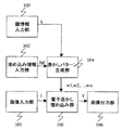
次に、透かしパターン生成部104の細部構成について説明する。図2は、透かしパターン生成部104の細部構成を示すブロック図である。図2に示すように、透かしパターン生成部104は、領域情報生成部201と、擬似乱数発生部202と、擬似乱数割り当て部203とから構成される。
【0024】
一方、領域情報生成部201によって、生成された領域情報mが擬似乱数割り当て部203に出力される。領域情報mとは、付加情報Infを構成する各ビットの位置と、それぞれのビットが埋め込まれる画像データI上の画素位置を対応付けるために用いられる行列で与えられた少領域内の各画素の属性情報である。図3は、4ビットから構成される付加情報Infを、画像データIに埋め込む場合に用いられる領域情報mの一例を示す図である。
【0025】
図3に示される例は、4ビットの付加情報Infを埋め込むために用いられる、4×4の領域情報mである。本実施形態では、領域情報mに示される領域と付加情報Infのビット位置が対応付けられているものとする。そして、領域情報m内の各要素に対して、第1の領域には「A」、あるいは、第2の領域には「B」というように領域内の各画素に対して属性情報が割り当てられている。具体的には、領域情報mに示される第1の領域Aに対して、4ビットの付加情報Infにおけるビット位置「1」のビット情報(最上位ビット)とビット位置「2」のビット情報(最上位ビットの次のビット)が埋め込まれる。
【0026】
同様にして、領域情報mに示される第2の領域Bに対して、付加情報Infのビット位置「3」のビット情報(最上位ビットから3番目のビット)とビット位置「4」のビット情報(最上位ビットから4番目のビット)が埋め込まれる。これによって、4×4の大きさの画素内に4ビットの付加情報を埋めることが可能となる。
【0027】
次に、擬似乱数発生部202では、入力された鍵情報kを初期値として、第1の擬似乱数列r1と第2の擬似乱数列r2とが生成される。生成された第1の擬似乱数列r1及び第2の擬似乱数列r2は、擬似乱数割り当て部203に出力される。ここで、第1の擬似乱数列r1及び第2の擬似乱数列r2には、{−1,1}の範囲に含まれる一様分布に従う実数列を用いる。擬似乱数列を生成する方法は公知の技術であるため、本実施形態での説明は省略する。
【0028】
さらに、擬似乱数割り当て部203には、領域情報生成部201で生成された領域情報mと、擬似乱数発生部202で発生した、第1の擬似乱数列r1及び第2の擬似乱数列r2と、埋め込み情報入力部102からの付加情報Infとが入力される。そして、入力された第1の擬似乱数列r1及び第2の擬似乱数列r2の各要素が、付加情報Infのビット数によって定められる領域情報mの所定の要素に割り当てられる。尚、領域情報mの所定の要素に乱数列が割り当てられた行列のことを、本実施形態では透かしパターンwnと呼ぶことにする。
【0029】
ここで、第1の擬似乱数列r1及び第2の擬似乱数列r2の各要素を、領域情報mの所定の要素に割り当てる処理の詳細について説明する。
【0030】
本実施形態では、付加情報Infを4ビットとし、図3に示した4×4の領域情報mを用いる。前述したように、領域情報mと2つの擬似乱数列(第1の擬似乱数列r1、第2の擬似乱数列r2)を用いることにより4ビットの付加情報を埋め込むことが可能である。以降では、4ビットの付加情報について、最初の2ビットを第1のビットセット、次の2ビットを第2のビットセットと呼ぶ。
【0031】
まず、第1のビットセットを領域情報mに示す第1の領域に割り当てる。第1の領域は、上述したように、値として「A」を持つ要素である。尚、割り当ての際、領域情報mに示す領域情報内の各要素のうち、第1の領域についてラスター走査し、図4に示すビット割り当て規則と第1のビットセットに従って、順に、第1の擬似乱数列r1、あるいは第2の擬似乱数列r2のいずれかの要素を割り当てる。図4は、本実施形態の擬似乱数割り当て部203で用いられるビット割り当て規則を示す図である。
【0032】
すなわち、第1の領域Aに埋め込まれる付加情報の第1のビットセットが「00」の場合は、第1の擬似乱数列r1内の各擬似乱数の符号を変化させないで、「A」の属性を持つ画素の位置に対してラスター走査順に擬似乱数を一つずつ割り当てる。同様にして、埋め込まれる付加情報の第1のビットセットが「01」の場合は、第1の擬似乱数列r1内の各擬似乱数の符号を逆にして(すなわち、各擬似乱数に−1を乗算して)、同様にして順に一つずつ割り当てる。また、付加情報の第1のビットセットが「10」のときは、第2の擬似乱数列r2内の擬似乱数の符号を変化させずに、付加情報の第1のビットセットが「11」のときは、第2の擬似乱数列r2内の擬似乱数の符号を逆にして割り当てる。
【0033】
次に、第2のビットセットを領域情報mに示す第2の領域に割り当てる。第2の領域は、上述したように、値として「B」をもつ要素である。尚、割り当ての際、領域情報mに示す領域情報内の各要素のうち、第2の領域をラスタ走査し、図4に示すビット割り当て規則と第2のビットセットに従って、第1のビットセットの場合と同様にして、第2の擬似乱数列r2、あるいは第1の擬似乱数列r1のいずれかの要素を割り当てる。
【0034】
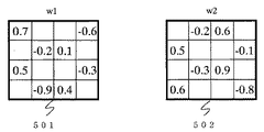
図5は、上述したようにして生成される、透かしパターンwnの一例を説明するための図である。図5では、埋め込まれる付加情報Infとして「0011」という4ビットの情報を用い、第1のビットセット「00」に対応する第1の擬似乱数列r1の「+r1」の擬似乱数r1={0.7,−0.6、−0.2,0.1,0.5、−0.3、−0.9.0.4}という実数列が第1の領域Aに対して割り当てられる。また、第2のビットセット「11」に対応する第2の擬似乱数列r2の「−r2」を割り当てるため、r2={0.2、−0.6、−0.5,0.1,0.3、−0.9、−0.6,0.8}に対して符号を逆にした実数列が割り当てられた場合の例が示されている。図5において、符号501は、第1のビットセット「00」を埋め込むための透かしパターンw1を示す。また、符号5402は、第2のビットセット「11」を埋め込むための透かしパターンw2を示す。
【0035】
尚、上述した実施形態においては、4ビットの付加情報を埋め込むために4×4の大きさの領域情報mを用いたが、本発明はこれに限られない。例えば、1ビット埋め込むために更に多くの画素を利用し、より大きなサイズの領域情報mを用いる場合も本発明の範疇に含まれる。そして、より大きなサイズの領域情報を用いた場合には、擬似乱数列もより長い実数列を用いることができる。これによって、より長い実数列を用いることによって、付加情報Infが埋め込まれているにも関わらず、集積画像と透かしパターンw1、w2、…、wnとの相関係数が小さくなることを防ぐことができる。例えば、64ビットの付加情報を埋め込むために、充填率を50%として、256×256の領域情報を用いる。この場合、1ビット埋め込むために512画素使用することになる。
【0036】
次に、電子透かし埋め込み部105について説明する。電子透かし埋め込み部105には、画像データI及び透かしパターンwnが入力される。そして、画像データIに透かしパターンwnが埋め込まれ、透かしパターンwnが埋め込まれた画像データI’が出力される。
【0037】
電子透かし埋め込み部105の処理の詳細について説明する。電子透かし埋め込み部105では、次式に従って、電子透かしの埋め込み処理が実行される。
【0038】

ここで、I’i,jは、電子透かしが埋め込まれた画像データを示す。また、Ii,jは、電子透かしが埋め込まれる前の画像データを示す。また、wni,jは透かしパターンを示す。但し、nは埋め込まれる付加情報Infのビット位置及び付加情報Infのビット位置に対応する透かしパターンwnを示す整数、i,jはそれぞれ画像データI及びI’、透かしパターンwnのx座標及びy座標を表すパラメータを示す。また、aは電子透かしの強度を設定するための係数である。例えば、4ビットから構成される付加情報Infを埋め込むために、nは1から2までの値をとる。
【0040】
係数aの値を大きく設定することによって耐性の強い電子透かしを埋め込むことが可能であるが、反面、画質劣化が大きくなる。一方、aの値を小さく設定することによって電子透かしの耐性は弱くなるが、画質劣化を小さくすることが可能である。このようにして、領域情報mの構成と同様に係数aの値を適切に設定することにより、電子透かしの内容変更に対する耐性と電子透かしを埋め込んだ後の画像の画質のバランスを設定することが可能である。
【0041】
図6は、式(1)に示した電子透かし埋め込み処理の具体例として、4×4の領域情報mを用いた場合の例を説明するための図である。図6において、符号601は式(1)における画像データI’、符号602は画像データI、符号603は透かしパラメータwnを表す。また、Eは、符号601〜603の行列と同じ大きさの単位行列である。式(1)における演算は、図6に示されるような行列内の各要素に対して実行される。
【0042】
図6に示されるパラメータを式(1)を用いて4×4の大きさの領域内で演算する処理は、実際には入力された画像データIの全体に対して繰り返し実行される。例えば、図7は、24×24画素から構成される画像データIを示す図である。図7に示すように、入力された画像データIは、4×4画素から構成される互いに重ならないブロックに分割され、分割されたそれぞれのブロックに対して、上述したような、図6のパラメータを用いて式(1)に示した同じ演算処理が繰り返し実行される。このように図6のパラメータを用いて式(1)に示された処理が実行されるブロックを、「マクロブロック」と呼ぶ。
【0043】
全てのマクロブロックに対して繰り返し、電子透かしによる付加情報の埋め込み処理を実行することにより、画像全体に対して付加情報を埋め込むことが可能である。尚、本実施形態では、1つのマクロブロックにはnビットから構成される付加情報Infを埋め込むことができる。このことから、少なくとも1つのマクロブロックからは、nビットの付加情報Infを抽出することができる。すなわち、nビットの付加情報Infが埋め込まれた画像データからその付加情報Infを抽出するためには、画像データIの全体の情報を必要とせず、画像データIの一部(少なくともnビットの付加情報が埋め込まれた1つのマクロブロック)があれば十分である。
【0044】
このように、画像データIの一部から電子透かしを完全に抽出可能であることを「切り取り耐性がある」と呼ぶ。そして、マクロブロック単位の電子透かし埋め込み処理を画像全体に繰り返し実行することにより、電子透かしに切り取り耐性を持たせることが可能である。
【0045】
すなわち、この発明は、画像の可視表示状態において、その存在を人間が知覚しにくいように、該画像を表す画像データ中にnビットの電子透かし情報を埋め込む情報処理装置であって、互いに異なる2n-2通りの係数値配列を設定する設定手段(透かしパターン生成部104)と、埋め込むべきnビットの電子透かし情報に基づいて、係数値配列のいずれか1つを選択する選択手段(透かしパターン生成部104)と、画像データを所定画素ブロックに分割し、各画素ブロック中の相対的同位置の画素データを、選択した係数値配列の所定の係数値を用いて補正し、他の相対的同位置の画素に対しても、順次他の係数値を用いて補正することで、nビットの電子透かし情報を埋め込む埋め込み手段(電子透かし埋め込み部105)とを備え、画素ブロックの画素群をQ個のグループに分け、各グループに対してnビットの電子透かし情報を埋め込むことで、Q×nビットの電子透かし情報を埋め込むことを特徴とする。
【0046】
さらに、本発明は、所定の鍵情報を入力する鍵情報入力手段(鍵情報入力部103)をさらに備え、設定手段(透かしパターン生成部104)が、入力された鍵情報にしたがって係数値配列を設定することを特徴とする。
【0047】
さらにまた、本発明は、疑似乱数列を用いて互いに異なる係数値配列を生成する疑似乱数生成手段(疑似乱数発生部202)をさらに備えることを特徴とする。
次に、上述した構成によって付加情報を画像データに埋め込む情報処理装置の動作手順について説明する。図8は、本実施形態による付加情報を埋め込むための情報処理装置の動作手順を説明するためのフローチャートである。
【0048】
まず、画像入力部101から、付加情報Infを埋め込む先の画像データIが入力される(ステップS801)。次に、埋め込み情報入力部102から、画像データIに埋め込む付加情報Infが入力される(ステップS802)。さらに、鍵情報入力部103から、画像データIに付加情報Infを埋め込む際に用いられる鍵情報kが入力される(ステップS803)。尚、画像データIと付加情報Infと鍵情報kの入力順は、この順に限られず、また同時であってもよい。
【0049】
そして、入力された付加情報Inf及び鍵情報kは、透かしパターン生成部104に出力され、そこで透かしパターンwnが生成される(ステップS804)。図9は、透かしパターン生成部104で行われる透かしパターンwnの生成手順を説明するためのフローチャートである。透かしパターン生成部104では、領域情報生成部201において、付加情報Infの大きさに基づいて、付加情報Infのビット数分の種類の属性情報を有する領域に分割された領域情報mが生成される(ステップS804a)。また、入力された鍵情報kを初期値として、擬似乱数発生部202において擬似乱数(例えば、上述したr1、r2)を発生させる(ステップS804b)。さらに、領域情報mと擬似乱数r1及びr2と付加情報Infが擬似乱数割り当て部203に入力され、そこで透かしパターン(例えば、上述したw1、w2)が生成される(ステップS804c)。
【0050】
こうして生成された透かしパターンが電子透かし埋め込み部105に入力され、そこで電子透かし埋め込み済みの画像データI’が生成される(ステップS805)。この画像データI’は、画像出力部106から電子透かしの埋め込み処理部の最終的な出力として出力される(ステップS806)。
【0051】
尚、本実施形態では、1枚の画像データを4×4画素のブロックに分割して、4ビットを埋め込む方法について記述したが、各ブロックに4ビット以上の電子透かし情報を埋め込んでもよい。また、1枚の画像データを複数の領域に分割し、各領域に対して上述した電子透かし情報埋め込み方法を適用することも可能である。この場合、例えば、画像データをp個の領域に分割し、各領域にqビットの電子透かし情報を埋め込むとすると、当該画像データにはp×qビットの電子透かし情報を埋め込むことができる。
【0052】
<第2の実施形態>
次に、第1の実施形態に示された方法によって画像に埋め込まれた電子透かし情報の抽出処理を行う情報処理装置について説明する。図10は、本実施形態における電子透かし情報の抽出処理を行う情報処理装置の構成を示すブロック図である。
【0053】
図10に示すように、電子透かし情報を抽出するための情報処理装置は、電子透かし埋め込み済みの画像データI”を入力するための画像入力部1001と、付加情報Inf’の抽出に用いられる鍵情報を入力するための鍵情報入力部1002と、透かしパターンを生成する透かしパターン生成部1003と、付加情報Inf’を抽出する電子透かし抽出部1004と、抽出した付加情報を出力する電子透かし出力部1005とから構成される。
【0054】
まず、画像入力部1001について説明する。画像入力部1001には、電子透かしが埋め込まれている可能性がある画像データI”が入力される。ここで、画像入力部1001の動作は、前述した画像入力部101と同様であるので詳細な動作の説明は省略する。
【0055】
尚、画像入力部1001から入力される画像データI”は、前述した電子透かし埋め込み部105によって付加情報が埋め込まれた画像データI’だけに限定されない。すなわち、付加情報が埋め込まれた画像データI’であってもよいし、画像データI’が内容変更された画像データであってもよい。更に、付加情報が何も埋め込まれていない画像データIであってもよい。
【0056】
次に、鍵情報入力部1002について説明する。鍵情報入力部1002からは、埋め込まれた付加情報を抽出するための鍵情報kが入力される。ここで、入力される鍵情報kは、第1の実施形態における鍵情報入力部103から入力されたものと同一でなければならない。すなわち、鍵情報入力部103から入力された鍵情報kと異なる鍵情報が入力された場合には、付加情報を埋め込んだときと同一の擬似乱数列を発生させることができないので、画像データに埋め込まれた付加情報を正しく抽出することができない。したがって、正しい鍵情報kを知る利用者だけに、正しい付加情報を抽出されるようにすることができる。
【0057】
次に、透かしパターン生成部1003について説明する。透かしパターン生成部1003には、鍵情報生成部1002から鍵情報kが入力され、入力された鍵情報kに基づいて透かしパターンwnが生成され、生成された透かしパターンwnが出力される。透かしパターン生成部1003は、透かしパターン生成部104と同様に、図2に示される各部を構成要素とし、透かしパターン生成部104とほぼ同様の処理が実行される。但し、擬似乱数割り当て部で実行される処理が第1の実施形態とは異なるので、ここでは擬似乱数割り当て部の処理について説明する。
【0058】
透かしパターン生成部1003における擬似乱数割り当て部には、領域情報生成部で生成された領域情報m、擬似乱数発生部で発生した第1の擬似乱数列r1、第2の擬似乱数列r2が入力され、第1の擬似乱数列、及び第2の擬似乱数列が領域情報mに従って割り当てられ、透かしパターンwnとして出力される。
【0059】
すなわち、透かしパターン生成部1003においては、まず、領域情報mに示す領域情報内の各要素のうち、値として「A」を持つ要素である第1の領域をラスター走査して、第1の擬似乱数列r1内の各擬似乱数を順に割り当てる。次に、値として「A」を持つ要素の第1の領域をラスター走査して、第2の擬似乱数列r2内の各擬似乱数を順に割り当てる。さらに、領域情報mに示す領域情報内の各要素のうち、値として「B」を持つ要素である第2の領域をラスター走査して、第1の擬似乱数列r1内の擬似乱数を順に割り当てる。そして、値として「B」を持つ要素の第2の領域をラスター走査して、第2の擬似乱数列r2内の各擬似乱数を順に割り当てる。
【0060】
図11は、第2の実施形態における透かしパターン生成部1003によって生成された、透かしパターンの一例を示す図である。図11では、第1の擬似乱数列r1として、r1={0.7,−0.6、−0.2,0.1,0.5、−0.3、−0.9.0.4}という実数列を用い、第2の擬似乱数列r2としてr2={0.2、−0.6、−0.5,0.1,0.3、−0.9、−0.6,0.8}という実数列を用いた。これらの擬似乱数は、上述した実施形態において付加情報を埋め込む場合に使用された擬似乱数と同様のものである。そして、これらの擬似乱数を、領域情報mとして図3に示す4×4の大きさの領域情報の例を用いた場合に生成されるA、Bの領域にr1、r2を割り当てることによって、透かしパターンw1〜w4が生成される。
【0061】
次に、電子透かし抽出部1004について説明する。電子透かし抽出部1004には、画像データI”及び透かしパターンw1、w2、w3、w4が入力される。そして、透かしパターンw1、w2、w3、w4を用いて画像データI”から付加情報Inf’が抽出される。尚、抽出された付加情報Inf’は、通常、埋め込んだ付加情報Infに等しいが、電子透かしを埋め込んだ画像データI’が種々の内容変更を受けている場合には、必ずしも付加情報Infと付加情報Inf’は一致しないこともある。
【0062】
本実施形態において、電子透かし抽出部1004では、入力された画像データI”から生成された集積画像と透かしパターンw1、w2、w3、w4との相互相関がそれぞれ計算される。ここで、集積画像とは、入力された画像データI”をマクロブロックの大きさ(領域情報の大きさ)の互いに重ならないブロックに分割し、分割されたそれぞれのブロックの要素の値の平均値を算出した画像である。
【0063】
図12は、集積画像1202についての具体例を説明するための図である。図12では、4×4画素の透かしパターンと24×24画素の画像1201が入力された場合の集積画像の例が示されている。図12において、符号1201は、24×24画素の画像データ1201が、4×4画素の互いに重ならないブロックに分割されている場合の例である。図12では、画像データ1201は、36個のブロックに分割されている。この36個のブロックの各要素の値の平均値を求めたものが集積画像1202である。そして、電子透かし抽出部1004では、このようにして生成された集積画像1202と透かしパターンw1、w2、w3、w4との相互相関がそれぞれ計算される。
【0064】
次に、相関係数を計算する具体的な方法について、集積画像1202と透かしパターンwnの相関係数ρを計算する場合を用いて説明する。相関係数ρは、集積画像をcとし、透かしパターンをwnとすると、それらの間の類似度を測定する統計量であり、次式で表すことができる。
【0065】
【数2】
ここで、c’及びwn’は、集積画像c、透かしパターンwnのそれぞれの要素から、それぞれの行列の要素の平均値を減算した値を要素とする行列である。本実施形態では、自然画像内の4×4画素の大きさの範囲では、極端に画素値が変化する場合が少ないと考えられるので、集積画像平均値を減算した値を要素を用いた。また、cTは、cの転置行列である。これによって、相関係数ρは、−1から+1の値の範囲の値となる。
【0067】
例えば、集積画像と透かしパターンwnとの相関係数ρは、正の相関が強い場合は+1に近づく。一方、集積画像と透かしパターンwnとの相関係数ρは、負の相関が強い場合は−1に近づく。ここで、「正の相関が強い」とは、「集積画像が大きいほど透かしパターンwnが大きくなる」というような関係である。また、「負の相関が強い」とは、「集積画像が大きいほど透かしパターンwnが小さくなる」というような関係である。また、集積画像と透かしパターンwnとが無相関の場合、相関係数ρは0となる。
【0068】
電子透かし抽出部1004では、上述した手順で算出された相互相関の結果によって、埋め込まれている付加情報Inf’が抽出される。尚、透かしパターンが複数の場合は、集積画像と各透かしパターンw1、w2、w3、w4との相関係数をそれぞれ算出し、算出された相互相関の結果により、図4に示されたビット割り当て規則を用いて、埋め込まれている付加情報Inf’が判断される。
【0069】
このようにして相互相関を求めることは、集積画像と透かしパターンw1、w2、…、wnとが、どの程度類似しているかを評価することに等しい。すなわち、図1に示される電子透かし埋め込み部105において、集積画像である画像データI”の中に、透かしパターンw1、w2、…、wnが埋め込まれている場合には、これらは比較的類似しており、この類似の度合いが相互相関値として算出される。また、透かしパターンwnが加えられて埋め込まれている場合には相互相関値は正となり、透かしパターンwnが減じられている場合には相互相関値は負になる。
【0070】
以上のことから、領域情報mに示す第1の領域Aに第1の擬似乱数列r1が加えられている場合、透かしパターンw1と集積画像との相関係数として、「1」に近い値が得られる。一方、領域情報mに示す第1の領域Aに第1の擬似乱数列r1が減じられている場合、透かしパターンw1と集積画像との相関係数として、「−1」に近い値が得られる。さらに、領域情報mに示す第1の領域に第1の擬似乱数列r1が加えられているか、あるいは、減じられている場合には、透かしパターンw2と集積画像との相関係数として「0」に近い値が得られる。
【0071】
以上のように、全ての透かしパターンw1、w2、w3、w4と集積画像との相関係数を算出する。こうして得られた相関係数から、図4に示したビット割り当て規則に基づいて、埋め込まれているビットセットを判断し、付加情報Infを抽出することが可能である。
【0072】
図13は、4ビットの付加情報「0011」が埋め込まれた集積画像から、透かしパラメータw1、w2、w3、w4を用いて、付加情報「0011」を抽出する過程を説明するための図である。
【0073】
まず、集積画像と4ビットの付加情報Inf’に対応した4つの透かしパターンw1、w2,w3、w4との相互相関値がそれぞれ算出される。入力された集積画像である画像データI’に付加情報Inf’が埋め込まれている場合、相関係数はそれぞれ「+1,0,0,−1」として算出される。ここで、透かしパターンw1及びw2と、集積画像との相関係数「+1,0」から、領域情報mに示す第1の領域には第1の擬似乱数列r1が加えられていることがわかる。そこで、図4に示されるビット割り当て規則により、第1のビットセットは「00」であると判断することができる。
【0074】
また、透かしパターンw3、透かしパターンw4、集積画像の相関係数「0,−1」から、領域情報mに示す第2の領域には第2の擬似乱数列r2が減じられていることがわかる。そこで、図4に示されるビット割り当て規則により、第2のビットセットは「11」であると判断することができる。以上のようにして、埋め込まれている付加情報Inf’「0011」を抽出することが可能である。
【0075】
このようにして抽出された付加情報Inf’は、電子透かし出力部1005から外部に出力される。この際、図1に示される電子透かし埋め込み部105において付加情報Infが埋め込まれる時に、誤り訂正符号化処理や暗号化処理が施されている場合には、それぞれ誤り訂正復号処理や暗号復号処理を実行するようにする。この場合は、その後、得られた情報が最終的に抽出されたバイナリデータ列からなる付加情報Inf’として出力されることになる。
【0076】
上述した実施形態においては、4ビットの情報を埋め込むための領域情報mとして第1の領域A及び第2の領域Bを用い、擬似乱数列として第1の擬似乱数列r1と第2の擬似乱数列r2を用いた。しかしながら、本発明はこれに限定されるものではなく、領域情報mとしてs個の領域を用い、擬似乱数列としてt個の擬似乱数列を用いることによって、s×tビットの情報を埋め込むことが可能である。
【0077】
すなわち、本発明は、人間が知覚しにくいように、nビットの電子透かし情報が埋め込まれた画像データから、電子透かし情報を抽出する情報処理装置であって、互いに異なる2n通りの係数値配列を設定する設定手段(透かしパターン生成部1003)と、埋め込むべきnビットの電子透かし情報に基づいて、係数値配列のいずれか1つを選択する選択手段(透かしパターン生成部1003)と、画像データを所定画素ブロックに分割し、各画素ブロック中の相対的同位置の画素データを、選択した係数値配列の所定の係数値を用いて補正し、他の相対的同位置の画素に対しても、順次他の係数値を用いて補正することで得られた補正値と、画素ブロックの画素データの平均値との相関を算出する相関算出手段(透かしパターン生成部1003)と、2n通りの係数値配列について算出された、所定画素ブロックについての相関の総和に基づいて、画素ブロックを補正した一の係数値配列を選択し、選択された係数値配列から埋め込まれたビットを抽出する抽出手段(電子透かし抽出部1004)とを備えることを特徴とする。
【0078】
また、本発明は、相関算出手段(透かしパターン生成部1003)が、画像データにおいて分割された所定の画素ブロックの平均画素ブロックを生成する平均値生成手段をさらに備え、抽出手段(電子透かし抽出部1004)が、生成された平均画素ブロックと2n通りの係数値配列についての算出された相関に基づいて、画素ブロックを補正した一の係数値配列を選択し、選択された係数値配列から埋め込まれたビットを抽出することを特徴とする。
【0079】
さらに、本発明は、電子透かし情報が埋め込まれた際に使用された鍵情報を入力する鍵情報入力手段(鍵情報入力部1002)をさらに備え、設定手段(透かしパターン生成部1003)が、入力された鍵情報に基づいて、互いに異なる2n通りの係数値配列を設定することを特徴とする。
【0080】
次に、上述した構成によって、画像データ中に埋め込まれた付加情報を抽出する情報処理装置の動作手順について説明する。図14は、本実施形態による付加情報を抽出するための情報処理装置の動作手順を説明するためのフローチャートである。
【0081】
まず、画像入力部1001から、付加情報が埋め込まれている画像データI”が入力される(ステップS1401)。次に、鍵情報入力部1002から、画像データI”から付加情報を抽出する際に用いられる鍵情報kが入力される(ステップS1402)。尚、画像データI”と鍵情報kの入力順は、この順に限られず、また同時であってもよい。また、鍵情報kは第1の実施形態で入力された付加情報を埋め込む際に用いられた鍵情報kと同一のものである。
【0082】
そして、入力された鍵情報kは、透かしパターン生成部1003に出力され、そこで透かしパターンwnが生成される(ステップS1403)。て生成された透かしパターンwn及び画像データI”が電子透かし抽出部1004に入力され、そこで上述した相関係数を用いて付加情報Inf’の抽出が行われる(ステップS1404)。抽出された付加情報Inf’は、電子透かし出力部1005から最終的な出力として外部へ出力される(ステップS1405)。
【0083】
<第3の実施形態>
以上、説明した第1の実施形態、及び第2の実施形態は、付加情報Infを効率的に埋め込む例として、4ビットの情報を二つの擬似乱数列(第1の擬似乱数列r1、及び第2の擬似乱数列r2)と二つの2次元の領域(第1の領域A、及び第2の領域B)を用いて埋め込む方法について述べた。しかしながら本発明はこれに限定されることはない。そこで、本実施形態では、より簡素化した例として、1ビットの情報を埋め込むために一つの1次元の領域と二つの擬似乱数列を用いる例について説明する。
【0084】
まずはじめに、本実施形態における電子透かし情報の埋め込み処理について説明する。
【0085】
本実施形態における電子透かし情報の埋め込み処理を行う情報処理装置の構成は図1、及び図2に示したものと同様のものを利用可能である。本実施形態においては、前記情報処理装置のうち擬似乱数割り当て部203における動作が第1の実施の形態とは異なる。そこで、以降では、擬似乱数割り当て部203の動作について詳細に説明する。
【0086】
擬似乱数割り当て部203には一つの1次元領域を表す領域情報m、1ビットから構成される付加情報Inf,及び二つの擬似乱数列r1、及びr2が入力される。入力された擬似乱数列r1、及びr2は、所定のビット割り当て規則に従って割り当てられ、擬似乱数列r1、及びr2が割り当てられた透かしパターンwが出力される。
【0087】
ここで、ビット割り当て規則の一例として、付加情報Infがビット「0」である場合には擬似乱数列r1を割り当て、一方で付加情報Infがビット「1」である場合には付加情報r2を割り当てるようにする。更に、割り当てる際には、全ての要素に対してラスタスキャン順に擬似乱数列を割り当てる。即ち、一つの1次元領域に対して擬似乱数列を割り当てる。
【0088】
こうして擬似乱数列が割り当てられた一つの透かしパターンwが擬似乱数割り当て部203から出力される。出力された透かしパターンwを用いて、後段の電子透かし埋め込み部において画像データIに施される処理は第1の実施形態と同様であるので説明は省略する。
【0089】
次に、本実施形態における電子透かし情報の抽出処理について説明する。
【0090】
本実施形態における電子透かし情報の抽出処理を行う情報処理装置の構成は図2、及び図10に示したものと同様のものを利用可能である。本実施形態においては、前記情報処理装置のうち透かしパターン生成部104、及び電子透かし抽出部1004における動作が第2の実施の形態とは異なる。そこで、以降では、透かしパターン生成部104、及び電子透かし抽出部1004の動作について説明する。
【0091】
透かしパターン生成部104には一つの1次元情報を表す領域情報m、及び二つの擬似乱数列r1、及びr2が入力され、擬似乱数列r1、及びr2が夫々割り当てられた透かしパターンw1、及びw2が出力される。ここで、擬似乱数列r1、及びr2は本実施の形態において電子透かし埋め込み処理の時に用いられた擬似乱数列r1、及びr2と同じでなければならない。更に、割り当てる方法も同様でなければならず、例えば前述したように全ての要素に対してラスタスキャン順に擬似乱数列を割り当てる。
【0092】
こうして擬似乱数列r1、及びr2が割り当てられた二つの透かしパターンw1、及びw2が擬似乱数割り当て部203から出力される。出力された透かしパターンw1、及びw2を用いて、後段の電子透かし抽出部1004において画像データI''に埋め込まれている付加情報Inf'が抽出される。
【0093】
電子透かし抽出部1004においては、第2の実施の形態において説明したように画像データI''から集積画像を生成し、生成された集積画像と前記透かしパターンw1及びw2の相互相関値を算出し、算出された相互相関値から付加情報Inf'を抽出する
例えば、前述したビット割り当て規則によって付加情報Inf'が埋め込まれている場合には、集積画像と擬似乱数列r1との相互相関値が+1に近い時、付加情報Inf'はビット「0」であると判断する。一方で集積画像と擬似乱数列r2との相互相関値が+1に近い時、付加情報Inf'はビット「1」であると判断する。こうして抽出された付加情報Inf'が出力される。
【0094】
<第4の実施形態>
以上、説明した第1の実施の形態、第2の実施の形態、及び第3の実施の形態は、数ビットから構成される付加情報Infを埋め込む方法を例をあげて説明した。しかしながら、本発明はこれに限定されることはなく、埋め込むべき付加情報を2以上の複数種類に分類して識別可能な状態において、複数種類の付加情報を埋め込める様にする場合に適宜対応可能な技術である。
本実施形態では、一つの画像内に、二つの領域と2つの擬似乱数列を用いて、2種類の付加情報(即ち、2つのID)を埋め込む例について説明する。
【0095】
まずはじめに、本実施形態における電子透かし情報の埋め込み処理について説明する。
【0096】
本実施形態における電子透かし情報の埋め込み処理を行う情報処理装置の構成は図1、及び図2に示したものと同様のものを利用可能である。本実施形態においては、前記情報処理装置のうち擬似乱数割り当て部203における動作が第1の実施の形態とは異なる。そこで、以降では、擬似乱数割り当て部20 3の動作について詳細に説明する。
【0097】
擬似乱数割り当て部203には二つの領域情報を表す領域情報m、及び2種類の付加情報ID1とID2,及び2つの擬似乱数列r1とr2が入力される。ここで、二つの領域情報として、本実施形態においては図3に示した領域情報を用いることにする。しかしながら本発明はこれに限定されることなく種々の領域情報を用いることが可能であり、他の領域情報の一例については別の実施形態として後述する。
【0098】
本実施形態においては、図3に示す領域のうち領域AにはID1、領域BにはID2を埋め込むこととする。更に、入力された付加情報ID1、及びID2は、夫々入力された擬似乱数列r1、及びr2に対応付けるものとする。即ち、領域Aには擬似乱数列r1が、領域Bには擬似乱数列r2が夫々割り当てられ、擬似乱数列が割り当てられた一つの透かしパターンwが擬似乱数割り当て部203から出力される。出力された透かしパターンwを用いて、後段の電子透かし埋め込み部において画像データIに施される処理は第1の実施の形態と同様であるので説明は省略する。
【0099】
次に、本実施形態における電子透かし情報の抽出処理について説明する。
【0100】
本実施形態における電子透かし情報の抽出処理を行う情報処理装置の構成は、図2、及び図10に示したものと同様のものを利用可能である。本実施形態においては、前記情報処理装置のうち透かしパターン生成部104、及び電子透かし抽出部1004における動作が第2の実施形態とは異なる。そこで、以降では、透かしパターン生成部104、及び電子透かし抽出部1004の動作について説明する。
【0101】
透かしパターン生成部104には領域情報m、及び2つの擬似乱数列r1、及びr2が入力され、擬似乱数列r1、及びr2が夫々割り当てられた透かしパターンw1、及びw2が出力される。ここで、擬似乱数列r1、及びr2は本実施の形態において電子透かし埋め込み処理の時に用いられた擬似乱数列r1、及びr2と同じでなければならない。
【0102】
こうして擬似乱数列r1、及びr2が割り当てられた2つの透かしパターンw1、及びw2が擬似乱数割り当て部203から出力される。出力された透かしパターンw1、及びw2を用いて、後段の電子透かし抽出部1004において画像データI''に埋め込まれている付加情報ID1及びID2が抽出される。
【0103】
電子透かし抽出部1004においては、第2の実施形態において説明したように画像データI''から集積画像を生成し、生成された集積画像と前記透かしパターンw1及びw2の相互相関値を算出し、算出された相互相関値から付加情報ID1及びID2を抽出する。
【0104】
例えば、画像データI''と透かしパターンw1との相互相関値が所定の値以上である場合、画像データI''にはID1が埋め込まれていると判断する。同様に、画像データI''と透かしパターンw2との相互相関値が所定の値以上である場合、画像データI''にはID2が埋め込まれていると判断する。このように処理することによって、一つの画像内に複数種類の付加情報を埋め込むことが可能となる。
【0105】
<第5の実施形態>
前記第4の実施形態においては一つの画像内に、図3に示したような領域情報を用いて2種類の付加情報を埋め込む例について説明した。本実施の形態においては、図3に示した領域情報の他の領域情報を用いる例について説明する。
更に、本実施の形態では、複数種類(ここでは2種類)の付加情報に重要度を設定し、重要度に応じた付加情報の埋め込みを行うことにより、重要度の高い付加情報をより確実に抽出する方法について説明する。
【0106】
図15に本実施形態において用いる領域情報の例を示す。図15(a)及び(b)に示す領域全体は入力された画像データと同じ面積を有する。図15(a)は画像データのうち中心部の領域を領域Aとし、外枠部の領域を領域Bとした場合の領域情報の例である。また、図15(b)は利用者により指定された任意の領域(被写体や画像中の主要な箇所など)を領域Aとし、それ以外の領域を領域Bとした場合の領域情報の例である。尚、図15に示す例はいずれも画像中で領域Aが領域Bよりも重要であるとした場合の例であり、各領域の位置関係は任意に設定可能である。
【0107】
尚、本実施形態においては図15に示すように画像データは何れかの領域に必ず含まれるように領域情報を設定した。この場合、画像データ全体に何れかの付加情報が電子透かしとして埋め込まれることになる。しかしながら、本発明はこれに限定されることなく、図18に示すように領域Cを設定し領域Cには擬似乱数列を割り当てず、即ちいずれの付加情報も埋め込まれないようにしてもよい。
【0108】
更に、本実施形態においては2種類の付加情報ID1とID2に重要度を設定する。ここでは、ID1はID2よりも重要であると設定する。そして、図15に示した領域AにはID1(重要度が大きい)、領域BにはID2(重要度が小さい)を割り当てて、埋め込む。このように処理することにより、付加情報が埋め込まれた画像データが、以後に種々の処理(切り取りなど)を施された場合にも、ID1(重要度が大きい)はID2(重要度が小さい)よりも確実に抽出することが可能となる。
【0109】
<第6の実施形態>
第5の実施形態においては、(実画像の)空間領域における領域情報を用い、更に2種類の付加情報に重要度を設定し、前記空間領域における領域情報と重要度に応じて付加情報を埋め込む例について説明した。しかしながら、本発明における領域情報は上記空間領域における領域情報に限定されることなく、空間周波数領域において電子透かしの埋め込みが行われる場合に適用するならば、その空間周波数領域に関する領域情報を用いることになる。以下、この形態について説明する。
【0110】
まず、電子透かし情報の埋め込み処理について説明する。
【0111】
本実施形態における電子透かし情報の埋め込み処理を行う情報処理装置の構成は図1、及び図2に示したものと同様のものを利用可能である。本実施形態においては、前記情報処理装置のうち電子透かし埋め込み部105、及び擬似乱数割り当て部203における動作が第1の実施の形態とは異なる。そこで、以降では、電子透かし埋め込み部105、及び擬似乱数割り当て部203の動作について詳細に説明する。
【0112】
まず、擬似乱数割り当て部203の動作について説明する。擬似乱数割り当て部203の動作は第4の実施形態と同様である。但し、本実施形態においては領域情報として空間周波数領域の領域情報を用いる。図17に本実施の形態で用いる領域情報の例を示す。
【0113】
図17(a)、(b)、(c)は、後述する空間周波数変換部において夫々離散ウェーブレット変換、離散コサイン変換、離散フーリエ変換を用いた場合の例であり、領域全体の面積は夫々の空間周波数変換の処理単位に等しい。図17に設定した領域は、各々の空間周波数変換の性質を考慮し、領域Aとして低周波成分、領域Bとして高周波成分が割り当てられるように設定してある。
【0114】
尚、本実施の形態においては図17に示すように画像データは何れかの領域に必ず含まれるように領域情報を設定した。この場合、画像データ全体に何れかの付加情報が電子透かしとして埋め込まれることになる。しかしながら、本発明はこれに限定されることなく、図19に示すように領域Cを設定し領域Cには擬似乱数列を割り当てず、即ちいずれの付加情報も埋め込まれないようにしてもよい。
【0115】
そして、第5の実施形態で述べたのと同様に、付加情報ID1とID2に重要度を設定する。ここでは、ID1はID2よりも重要であると設定し、擬似乱数列r1,及びr2を、夫々領域A、及び領域Bに割り当てる。そして、擬似乱数列が割り当てられた一つの透かしパターンwが擬似乱数列割り当て部203から出力される。
【0116】
次に、電子透かし埋め込み部105の細部構成について説明する。図16は、電子透かし埋め込み部105の細部構成を示すブロック図である。図16に示すように、電子透かし埋め込み部105は、空間周波数変換部161と、加算部162と、逆周波数変換部163とから構成されている。
【0117】
電子透かし埋め込み部105に入力された画像データIは空間周波数変換部161において、空間周波数変換処理が施され、空間周波数変換された係数が出力される。ここで、空間周波数変換処理として、離散ウェーブレット変換、離散コサイン変換、離散フーリエ変換などを用いることが可能である。空間周波数変換処理された係数に対して加算部162において、入力された透かしパターンwが加えられる。
【0118】
そして、透かしパターンwが加えられた係数が逆空間周波数変換部163に入力され、逆空間周波数変換部162において逆周波数変換処理が施されたデータがI'として出力される。
【0119】
次に、本実施形態における電子透かし情報の抽出処理について説明する。
【0120】
本実施形態における電子透かし情報の抽出処理を行う情報処理装置の構成は
図2、及び図10に示したものと同様のものを利用可能である。本実施形態においては、前記情報処理装置のうち透かしパターン生成部104、及び電子透かし抽出部1004における動作が第2の実施の形態とは異なる。そこで、以降では、透かしパターン生成部104、及び電子透かし抽出部1004の動作について説明する。
【0121】
まず、透かしパターン生成部104の動作について説明する。擬似乱数割り当て部203の動作は第4の実施形態と同様である。但し、本実施形態においては領域情報として、前記電子透かし埋め込み処理において用いられたものと同様の領域情報を用いなければならない。
【0122】
次に、電子透かし抽出部1004の細部構成について説明する。図20は、電子透かし抽出部1004の細部構成を示すブロック図である。図20に示すように、電子透かし抽出部1004は、空間周波数変換部2001と、相関算出部2002とから構成されている。
【0123】
電子透かし抽出部1004に入力された画像データI''は空間周波数変換部2001において、空間周波数変換処理が施され、空間周波数変換された係数が出力される。ここで用いる空間周波数変換処理は、前述した電子透かし埋め込み処理において実行された処理と同様の処理でなければならない。
【0124】
次に、空間周波数変換処理された係数に対して相関算出部2002において、入力された透かしパターンw1、及びw2と空間周波数変換された係数の相互相関値が算出される。そして、透かしパターンw1と空間周波数変換された係数の相互相関値が所定の値よりも大きい場合は、画像データI''には付加情報ID1が埋め込まれていると判断する。また、透かしパターンw2と空間周波数変換された係数の相互相関値が所定の値よりも大きい場合には、画像データI''には付加情報ID2が埋め込まれていると判断する。
【0125】
このように処理することにより、付加情報が埋め込まれた画像データが、以後に種々の処理(ローパスフィルタリングや非可逆圧縮など)を施された場合にも、ID1(重要度が大きい)はID2(重要度が小さい)よりも確実に抽出することが可能となる。
【0126】
尚、本発明は、複数の機器(例えば、ホストコンピュータ、インタフェース機器、リーダ、プリンタ等)から構成されるシステムに適用しても、一つの機器からなる装置(例えば、複写機、ファクシミリ装置等)に適用してもよい。
【0127】
また、本発明の目的は、前述した実施形態の機能を実現するソフトウェアのプログラムコードを記録した記録媒体(又は記憶媒体)を、システムあるいは装置に供給し、そのシステムあるいは装置のコンピュータ(又はCPUやMPU)が記録媒体に格納されたプログラムコードを読み出し実行することによっても、達成されることは言うまでもない。この場合、記録媒体から読み出されたプログラムコード自体が前述した実施形態の機能を実現することになり、そのプログラムコードを記録した記録媒体は本発明を構成することになる。
【0128】
また、コンピュータが読み出したプログラムコードを実行することにより、前述した実施形態の機能が実現されるだけでなく、そのプログラムコードの指示に基づき、コンピュータ上で稼働しているオペレーティングシステム(OS)などが実際の処理の一部又は全部を行い、その処理によって前述した実施形態の機能が実現される場合も含まれることは言うまでもない。
【0129】
さらに、記録媒体から読み出されたプログラムコードが、コンピュータに挿入された機能拡張カードやコンピュータに接続された機能拡張ユニットに備わるメモリに書込まれた後、そのプログラムコードの指示に基づき、その機能拡張カードや機能拡張ユニットに備わるCPUなどが実際の処理の一部又は全部を行い、その処理によって前述した実施形態の機能が実現される場合も含まれることは言うまでもない。
【0130】
本発明を上記記録媒体に適用する場合、その記録媒体には、先に説明したフローチャートに対応するプログラムコードが格納されることになる。
【0131】
【発明の効果】
以上説明したように、本発明によれば、1つの画像内に複数種類、或いは多ビットの付加情報を埋め込むことが可能である。
【0132】
また、上記複数種類、或いは多ビットの付加情報を1画像内に、実画像空間や周波数空間の状態で埋め込む際に、その付加情報の各部分の重要度に応じて、その各部分の以後の取扱いを配慮した埋め込みを行うので、重要度の高い部分の付加情報について、確実にその付加情報を抽出/検出できる。
【図面の簡単な説明】
【図1】本実施形態による電子透かし情報の埋め込み処理を行う情報処理装置の構成を示すブロック図である。
【図2】透かしパターン生成部104の細部構成を示すブロック図である。
【図3】4ビットから構成される付加情報Infを、画像データIに埋め込む場合に用いられる領域情報mの一例を示す図である。
【図4】本実施形態の擬似乱数割り当て部203で用いられるビット割り当て規則を示す図である。
【図5】上述したようにして生成される、透かしパターンwnの一例を説明するための図である。
【図6】式(1)に示した電子透かし埋め込み処理の具体例として、4×4の領域情報mを用いた場合の例を説明するための図である。
【図7】24×24画素から構成される画像データIを示す図である。
【図8】本実施形態による付加情報を埋め込むための情報処理装置の動作手順を説明するためのフローチャートである。
【図9】透かしパターン生成部104で行われる透かしパターンwnの生成手順を説明するためのフローチャートである。
【図10】本実施形態における電子透かし情報の抽出処理を行う情報処理装置の構成を示すブロック図である。
【図11】第2の実施形態における透かしパターン生成部1003によって生成された、透かしパターンの一例を示す図である。
【図12】集積画像についての具体例を説明するための図である。
【図13】4ビットの付加情報「0011」が埋め込まれた集積画像から、透かしパラメータw1、w2、w3、w4を用いて、付加情報「0011」を抽出する過程を説明するための図である。
【図14】本実施形態による付加情報を抽出するための情報処理装置の動作手順を説明するためのフローチャートである。
【図15】第5の実施形態における領域情報mの一例を示す図である。
【図16】第6の実施形態における電子透かし埋め込み部の構成を示すブロック図である。
【図17】第6の実施形態における領域情報mの一例を示す図である。
【図18】第5の実施形態における領域情報mの変形例を示す図である。
【図19】第6の実施形態における領域情報mの変形例を示す図である。
【図20】第6の実施形態における電子透かし抽出部の構成を示すブロック図である。
【符号の説明】
101、1001 画像入力部
102 埋め込み情報入力部
103、1002 鍵情報入力部
104、1003 透かしパターン生成部
105 電子透かし埋め込み部
106 画像出力部
201 領域情報生成部
202 擬似乱数発生部
203 擬似乱数割り当て部
1004 電子透かし抽出部
1005 電子透かし出力部[0001]
BACKGROUND OF THE INVENTION
The present invention extracts an additional information from the image data in which the additional information is embedded, and an information processing apparatus that embeds the additional information using a digital watermark, and a control method thereof, so that the image data is less visible to human eyes. The present invention relates to an information processing apparatus and a control method thereof.
[0002]
[Prior art]
In recent years, various information such as document data, image data, and audio data has been digitized due to the rapid development and spread of computers and their networks. Digital information is not deteriorated due to aging and can be stored indefinitely. On the other hand, it is easy to copy by a third party, and copyright protection is a big problem. Against this background, the importance of security technology for copyright protection is rapidly increasing.
[0003]
One technique for protecting copyright is “digital watermarking”. Digital watermarking embeds information such as the name of the copyright holder and the purchaser's ID in digitized image data, audio data, document data, etc. so that it is difficult for humans to perceive. This technology tracks unauthorized use.
[0004]
Conventionally, a method using a pseudo-random number sequence is known as a method for embedding a digital watermark. For example, in order to be able to embed any one of a plurality of types of additional information, each pseudo-random number sequence corresponding to each of the additional information is prepared, and one additional information to be embedded is prepared. A technique for embedding additional information by modulating image data using a corresponding pseudo-random number sequence is known.
[0005]
In this technique, it is possible to extract additional information from post-embedding image data by performing a convolution operation using a pseudorandom number sequence corresponding to the pseudorandom number sequence used at the time of embedding.
[0006]
[Problems to be solved by the invention]
However, in the above conventional technique, it is normal to embed one type of additional information using any one pseudo-random number sequence for one image, and there is still no technique for increasing the amount of additional information that can be embedded. It was not established.
[0007]
The present invention has been made in view of the above conventional example, and has as its main object to embed a plurality of types or multiple bits of additional information in one image.
[0008]
Furthermore, according to the present invention, when embedding the above-described multiple types or multi-bit additional information in one image in the state of the real image space or the frequency space, each of the additional information depends on the importance of each part. By embedding considering the subsequent handling of the part,
Another object is to ensure that additional information in a highly important part can be extracted / detected with certainty.
[0009]
[Means for Solving the Problems]
In order to solve the above problems, the present invention is an information processing apparatus that embeds digital watermark information in image data representing an image so that the presence of the image in a visible display state is difficult for humans to perceive. Area information generating means for generating area information for specifying at least two areas in the real image space / frequency space represented by the image data, coefficient value series generating means for setting at least two coefficient value series different from each other,Identified by area informationBy assigning the coefficient value series based on the digital watermark information to be embedded for each of the regions that have been embedded, and by changing the image data using the watermark pattern, the watermark pattern generation means for generating a watermark pattern, And an embedding means for embedding digital watermark information.The watermark pattern generation unit assigns the coefficient value series to each region specified by the region information according to the digital watermark information and the importance of the digital watermark information.It is characterized by that.
[0010]
In addition, the present invention provides image data representing an image so that it is difficult for humans to perceive the presence of the image in a visible display state.Q ×An information processing apparatus for embedding n-bit digital watermark information, which is different from each other.nSetting means for setting a street coefficient value array, selection means for selecting any one of the coefficient value arrays based on n-bit digital watermark information to be embedded, and the image datapluralDividing into pixel blocks, correcting pixel data at the same relative position in each pixel block using a predetermined coefficient value of the selected coefficient value array, and other pixels at the same relative positiondataAnd an embedding unit that embeds n-bit digital watermark information by sequentially correcting using other coefficient values,The embedding means isQ pixel blocksregionDivided into eachregionIn this case, the electronic watermark information of Q × n bits is embedded by embedding digital watermark information of n bits.
[0011]
Furthermore, the present invention is an information processing apparatus that extracts digital watermark information from image data in which n-bit digital watermark information is embedded so that it is difficult for humans to perceive.nSetting means for setting a coefficient value array, selection means for selecting any one of the coefficient value arrays based on n-bit digital watermark information to be extracted, and dividing the image data into predetermined pixel blocks Then, the pixel data at the same relative position in each pixel block is corrected using a predetermined coefficient value in the selected coefficient value array, and other relative pixels are sequentially changed to other coefficients. Correlation calculating means for calculating a correlation between a correction value obtained by correction using a numerical value and an average value of pixel data of the pixel block;nBased on the sum of correlations for a given pixel block calculated for each coefficient value array, a coefficient value array at a position where the pixel block is corrected is selected, and embedded bits are extracted from the selected coefficient value array. And an extracting means.
[0012]
DETAILED DESCRIPTION OF THE INVENTION
Hereinafter, an information processing apparatus according to an embodiment of the present invention will be described with reference to the drawings.
[0013]
<First Embodiment>
First, an information processing apparatus that performs a process of embedding additional information using a digital watermark will be described. FIG. 1 is a block diagram illustrating a configuration of an information processing apparatus that performs digital watermark information embedding processing according to the present embodiment.
[0014]
As shown in FIG. 1, an information processing apparatus according to the present invention includes an
[0015]
The
[0016]
When embedding digital watermark information in color image data, for example, each component of RGB components, luminance, and color difference components, which are a plurality of color components, is treated in the same way as a monochrome multi-value image. Can be realized by embedding digital watermark information. In such a case, it is possible to embed approximately three times the amount of data as compared with the case where digital watermark information is embedded in a monochrome multi-valued image. Conversely, the digital watermark information may be embedded only in a part of the plurality of components. In this case, the amount of data that can be embedded is the same as that embedded in the black-and-white image data. This has the effect of making it difficult to identify the target component from others.
[0017]
The embedded
[0018]
The additional information Inf input from the embedded
[0019]
Note that the additional information Inf itself may be encrypted so that it is not easily abused by a third party. Further, even when the content change is performed by the malicious person so that the embedded additional information Inf cannot be extracted from the image data I in which the additional information Inf is embedded with a digital watermark, the additional information Inf is correctly displayed. May be subjected to error correction coding.
[0020]
Note that the content change to the image data I ′ in which the additional information Inf is embedded includes not only intentional changes from a third party as described above but also unintentional content changes. For example, by applying image processing such as irreversible compression, luminance correction, geometric transformation, and filtering of an image, the digital watermark information may be affected as a result. Note that details of processing such as encryption and error correction coding are well-known, and thus description thereof will be omitted.
[0021]
The key information k input from the key
[0022]
The key information k is output to a pseudo-random
[0023]
Next, a detailed configuration of the watermark
[0024]
On the other hand, the region
[0025]
The example shown in FIG. 3 is 4 × 4 area information m used to embed 4-bit additional information Inf. In the present embodiment, it is assumed that the area indicated by the area information m is associated with the bit position of the additional information Inf. For each element in the area information m, attribute information is assigned to each pixel in the area, such as “A” in the first area or “B” in the second area. ing. Specifically, with respect to the first area A indicated by the area information m, bit information (most significant bit) of bit position “1” and bit information of bit position “2” (4-bit additional information Inf) The next bit of the most significant bit) is embedded.
[0026]
Similarly, for the second area B indicated by the area information m, the bit information (the third bit from the most significant bit) of the additional information Inf and the bit information of the bit position “4”. (4th bit from the most significant bit) is embedded. This makes it possible to embed 4-bit additional information in a 4 × 4 pixel.
[0027]
Next, the pseudo random
[0028]
Further, the pseudo random
[0029]
Here, details of a process of assigning each element of the first pseudo-random number sequence r1 and the second pseudo-random number sequence r2 to a predetermined element of the area information m will be described.
[0030]
In this embodiment, the additional information Inf is 4 bits, and the 4 × 4 area information m shown in FIG. 3 is used. As described above, it is possible to embed 4-bit additional information by using the area information m and two pseudo random number sequences (first pseudo random number sequence r1 and second pseudo random number sequence r2). Hereinafter, for the 4-bit additional information, the first 2 bits are referred to as a first bit set, and the next 2 bits are referred to as a second bit set.
[0031]
First, the first bit set is assigned to the first area indicated by the area information m. As described above, the first area is an element having “A” as a value. In the allocation, raster scanning is performed for the first region among the elements in the region information indicated by the region information m, and the first pseudo-sequentially is performed in accordance with the bit allocation rule and the first bit set illustrated in FIG. Any element of the random number sequence r1 or the second pseudo random number sequence r2 is assigned. FIG. 4 is a diagram showing a bit allocation rule used in the pseudo random
[0032]
That is, when the first bit set of the additional information embedded in the first area A is “00”, the sign of each pseudorandom number in the first pseudorandom number sequence r1 is not changed, and the attribute of “A” One pseudorandom number is assigned to each pixel position in the order of raster scanning. Similarly, when the first bit set of the additional information to be embedded is “01”, the sign of each pseudorandom number in the first pseudorandom number sequence r1 is reversed (that is, −1 is set to each pseudorandom number). Multiply) and assign one by one in the same way. When the first bit set of the additional information is “10”, the sign of the pseudo random number in the second pseudo random number sequence r2 is not changed, and the first bit set of the additional information is “11”. At this time, the sign of the pseudo random number in the second pseudo random number sequence r2 is assigned in reverse.
[0033]
Next, the second bit set is allocated to the second area indicated by the area information m. As described above, the second region is an element having “B” as a value. In the allocation, the second area among the elements in the area information indicated by the area information m is raster-scanned, and the first bit set according to the bit allocation rule and the second bit set shown in FIG. Similarly to the case, either the second pseudo random number sequence r2 or the first pseudo random number sequence r1 is assigned.
[0034]
FIG. 5 is a diagram for explaining an example of the watermark pattern wn generated as described above. In FIG. 5, 4-bit information “0011” is used as the additional information Inf to be embedded, and the pseudorandom number r1 = “0” of the first pseudorandom number sequence r1 corresponding to the first bit set “00”. .7, -0.6, -0.2, 0.1, 0.5, -0.3, -0.9.0.4} are assigned to the first region A. Further, in order to assign “−r2” of the second pseudo random number sequence r2 corresponding to the second bit set “11”, r2 = {0.2, −0.6, −0.5, 0.1, An example is shown in which a real number sequence having the opposite sign is assigned to 0.3, −0.9, −0.6, 0.8}. In FIG. 5,
[0035]
In the above-described embodiment, the area information m having a size of 4 × 4 is used to embed 4-bit additional information, but the present invention is not limited to this. For example, a case where more pixels are used for embedding 1 bit and area information m having a larger size is used is also included in the scope of the present invention. When larger area information is used, a longer real number sequence can be used as the pseudo random number sequence. Thus, by using a longer real number sequence, it is possible to prevent the correlation coefficient between the accumulated image and the watermark patterns w1, w2,... Wn from becoming small even though the additional information Inf is embedded. it can. For example, in order to embed 64-bit additional information, 256 × 256 area information is used with a filling rate of 50%. In this case, 512 pixels are used to embed 1 bit.
[0036]
Next, the digital
[0037]
Digital watermark embedding part105Details of the process will be described. Digital watermark embedding part105Then, an electronic watermark embedding process is executed according to the following equation.
[0038]
Where I ’i, jIndicates image data in which a digital watermark is embedded. Ii, jIndicates image data before the digital watermark is embedded. Wni, jIndicates a watermark pattern. Here, n is an integer indicating the bit position of the embedded additional information Inf and the watermark pattern wn corresponding to the bit position of the additional information Inf, i and j are the image data I and I ′, and the x and y coordinates of the watermark pattern wn, respectively. The parameter which represents is shown. Further, a is a coefficient for setting the strength of the digital watermark. For example, in order to embed additional information Inf composed of 4 bits, n takes a value from 1 to 2.
[0040]
By setting a large value for the coefficient a, it is possible to embed a strong digital watermark, but on the other hand, degradation of image quality increases. On the other hand, by setting the value of a to be small, the resistance of the digital watermark is weakened, but the image quality deterioration can be reduced. In this way, by appropriately setting the value of the coefficient a in the same manner as the configuration of the area information m, it is possible to set the balance between the resistance to digital watermark content change and the image quality of the image after embedding the digital watermark. Is possible.
[0041]
FIG. 6 is a diagram for explaining an example in which 4 × 4 area information m is used as a specific example of the digital watermark embedding process shown in Expression (1). In FIG. 6, reference numeral 601 represents image data I ′ in the equation (1),
[0042]
The process of calculating the parameters shown in FIG. 6 in the area of 4 × 4 size using the formula (1) is actually repeatedly performed on the entire input image data I. For example, FIG. 7 is a diagram showing image data I composed of 24 × 24 pixels. As shown in FIG. 7, the input image data I is divided into non-overlapping blocks composed of 4 × 4 pixels, and the parameters shown in FIG. The same calculation process shown in the expression (1) is repeatedly executed using. A block in which the process shown in Expression (1) is executed using the parameters in FIG. 6 is called a “macroblock”.
[0043]
It is possible to embed additional information in the entire image by repeatedly executing processing for embedding additional information by digital watermarking for all macroblocks. In the present embodiment, additional information Inf composed of n bits can be embedded in one macroblock. Thus, n-bit additional information Inf can be extracted from at least one macroblock. That is, in order to extract the additional information Inf from the image data in which the n-bit additional information Inf is embedded, the entire information of the image data I is not required, and a part of the image data I (at least n-bit additional information is added). One macroblock with embedded information) is sufficient.
[0044]
In this way, the ability to completely extract a digital watermark from a part of the image data I is referred to as “having clipping resistance”. Then, by repeatedly executing the digital watermark embedding process in units of macroblocks on the entire image, it is possible to make the digital watermark resistant to clipping.
[0045]
That is, the present invention is an information processing apparatus that embeds n-bit digital watermark information in image data representing an image so that it is difficult for a human to perceive the presence of the image in a visible display state.n-2A setting unit (watermark pattern generation unit 104) for setting a street coefficient value array and a selection unit (watermark pattern generation unit 104) for selecting one of the coefficient value arrays based on n-bit digital watermark information to be embedded. ), The image data is divided into predetermined pixel blocks, the pixel data at the same relative position in each pixel block is corrected using the predetermined coefficient value of the selected coefficient value array, and the other relative same position is corrected. The pixel also includes an embedding unit (digital watermark embedding unit 105) that embeds n-bit digital watermark information by sequentially correcting using other coefficient values, and the pixel group of the pixel block is divided into Q groups. In other words, the digital watermark information of Q × n bits is embedded by embedding the digital watermark information of n bits in each group.
[0046]
Further, the present invention further includes key information input means (key information input section 103) for inputting predetermined key information, and the setting means (watermark pattern generation section 104) converts the coefficient value array according to the input key information. It is characterized by setting.
[0047]
Furthermore, the present invention is characterized by further comprising pseudo-random number generation means (pseudo-random number generator 202) that generates different coefficient value arrays using a pseudo-random number sequence..
Next, an operation procedure of the information processing apparatus that embeds additional information in image data with the above-described configuration will be described. FIG. 8 is a flowchart for explaining an operation procedure of the information processing apparatus for embedding the additional information according to the present embodiment.
[0048]
First, the image data I to which the additional information Inf is embedded is input from the image input unit 101 (step S801). Next, additional information Inf to be embedded in the image data I is input from the embedded information input unit 102 (step S802). Furthermore, key information k used when embedding the additional information Inf in the image data I is input from the key information input unit 103 (step S803). Note that the input order of the image data I, the additional information Inf, and the key information k is not limited to this order, and may be simultaneous.
[0049]
The input additional information Inf and key information k are output to the watermark
[0050]
The watermark pattern generated in this way is input to the digital
[0051]
In the present embodiment, a method has been described in which one piece of image data is divided into 4 × 4 pixel blocks and 4 bits are embedded. However, digital watermark information of 4 bits or more may be embedded in each block. It is also possible to divide a piece of image data into a plurality of areas and apply the above-described digital watermark information embedding method to each area. In this case, for example, if image data is divided into p areas and q-bit digital watermark information is embedded in each area, p × q-bit digital watermark information can be embedded in the image data.
[0052]
<Second Embodiment>
Next, an information processing apparatus that performs extraction processing of digital watermark information embedded in an image by the method shown in the first embodiment will be described. FIG. 10 is a block diagram illustrating a configuration of an information processing apparatus that performs digital watermark information extraction processing according to the present embodiment.
[0053]
As shown in FIG. 10, an information processing apparatus for extracting digital watermark information includes an
[0054]
First, the
[0055]
The image data I ″ input from the
[0056]
Next, the key information input unit 1002 will be described. Key information k for extracting the embedded additional information is input from the key information input unit 1002. Here, the input key information k must be the same as that input from the key
[0057]
Next, the watermark pattern generation unit 1003 will be described. The watermark pattern generation unit 1003 receives the key information k from the key information generation unit 1002, generates a watermark pattern wn based on the input key information k, and outputs the generated watermark pattern wn. Similar to the watermark
[0058]
The pseudorandom number assignment unit in the watermark pattern generation unit 1003 receives the region information m generated by the region information generation unit, the first pseudorandom number sequence r1 and the second pseudorandom number sequence r2 generated by the pseudorandom number generation unit. , The first pseudo random number sequence and the second pseudo random number sequence are assigned according to the area information m, and are output as a watermark pattern wn.
[0059]
That is, in the watermark pattern generation unit 1003, first, among the elements in the area information indicated by the area information m, the first area which is an element having “A” as a value is raster-scanned to obtain the first pseudo Each pseudorandom number in the random number sequence r1 is assigned in order. Next, the first region of the element having “A” as a value is raster-scanned, and each pseudo-random number in the second pseudo-random number sequence r2 is assigned in order. Further, among the elements in the area information indicated by the area information m, the second area that is an element having “B” as a value is raster-scanned, and the pseudorandom numbers in the first pseudorandom number sequence r1 are sequentially assigned. . Then, the second region of the element having “B” as a value is raster-scanned, and each pseudo-random number in the second pseudo-random number sequence r2 is assigned in order.
[0060]
FIG. 11 is a diagram illustrating an example of a watermark pattern generated by the watermark pattern generation unit 1003 according to the second embodiment. In FIG. 11, as the first pseudorandom number sequence r1, r1 = {0.7, -0.6, -0.2, 0.1, 0.5, -0.3, -0.9.0. 4} and r2 = {0.2, −0.6, −0.5, 0.1, 0.3, −0.9, −0.6 as the second pseudorandom number sequence r2. , 0.8} is used. These pseudo random numbers are the same as the pseudo random numbers used when the additional information is embedded in the above-described embodiment. Then, by assigning r1 and r2 to the A and B areas generated when these pseudorandom numbers are used as the area information m and the example of the area information of 4 × 4 size shown in FIG. Patterns w1 to w4 are generated.
[0061]
Next, the digital watermark extraction unit 1004 will be described. The digital watermark extraction unit 1004 receives the image data I ″ and the watermark patterns w1, w2, w3, and w4. The additional information Inf ′ is obtained from the image data I ″ using the watermark patterns w1, w2, w3, and w4. Is extracted. The extracted additional information Inf ′ is usually equal to the embedded additional information Inf. However, if the image data I ′ embedded with the digital watermark has undergone various content changes, it is not necessarily added to the additional information Inf. The information Inf ′ may not match.
[0062]
In the present embodiment, the digital watermark extraction unit 1004 calculates the cross-correlation between the integrated image generated from the input image data I ″ and the watermark patterns w1, w2, w3, and w4. Here, the integrated image is calculated. Is an image obtained by dividing the input image data I ″ into blocks that do not overlap with each other in the size of the macroblock (the size of the region information), and calculating the average value of the elements of the divided blocks. is there.
[0063]
FIG. 12 is a diagram for explaining a specific example of the integrated image 1202. FIG. 12 shows an example of an integrated image when a watermark pattern of 4 × 4 pixels and an image 1201 of 24 × 24 pixels are input. In FIG. 12, reference numeral 1201 is an example in which the image data 1201 of 24 × 24 pixels is divided into 4 × 4 pixel blocks that do not overlap each other. In FIG. 12, the image data 1201 is divided into 36 blocks. The average value of the values of the elements of the 36 blocks is the accumulated image 1202. The digital watermark extraction unit 1004 calculates cross-correlations between the integrated image 1202 generated in this way and the watermark patterns w1, w2, w3, and w4.
[0064]
Next, a specific method for calculating the correlation coefficient will be described using the case of calculating the correlation coefficient ρ between the integrated image 1202 and the watermark pattern wn. The correlation coefficient ρ is a statistic for measuring the degree of similarity between c and the watermark pattern wn, and can be expressed by the following equation.
[0065]
[Expression 2]
Here, c ′ and wn ′ are matrices whose elements are values obtained by subtracting the average value of the elements of each matrix from the elements of the integrated image c and the watermark pattern wn. In the present embodiment, since it is considered that there are few cases where the pixel value changes extremely in the range of the size of 4 × 4 pixels in the natural image, the element is used as a value obtained by subtracting the integrated image average value. CTIs a transposed matrix of c. Accordingly, the correlation coefficient ρ becomes a value in the range of −1 to +1.
[0067]
For example, the correlation coefficient ρ between the integrated image and the watermark pattern wn approaches +1 when the positive correlation is strong. On the other hand, the correlation coefficient ρ between the integrated image and the watermark pattern wn approaches −1 when the negative correlation is strong. Here, “positive correlation is strong” is a relationship such that “the larger the accumulated image, the larger the watermark pattern wn”. Also, “strong negative correlation” is a relationship such that “the larger the accumulated image, the smaller the watermark pattern wn”. When the integrated image and the watermark pattern wn are uncorrelated, the correlation coefficient ρ is 0.
[0068]
The digital watermark extraction unit 1004 extracts the embedded additional information Inf ′ based on the cross-correlation result calculated by the above-described procedure. When there are a plurality of watermark patterns, correlation coefficients between the accumulated image and each of the watermark patterns w1, w2, w3, and w4 are calculated, and the bit allocation shown in FIG. 4 is calculated based on the calculated cross-correlation results. Using the rule, the embedded additional information Inf ′ is determined.
[0069]
Obtaining the cross-correlation in this way is equivalent to evaluating how similar the integrated image and the watermark patterns w1, w2,. That is, in the digital
[0070]
From the above, when the first pseudo-random number sequence r1 is added to the first area A indicated by the area information m, a value close to “1” is obtained as the correlation coefficient between the watermark pattern w1 and the integrated image. can get. On the other hand, when the first pseudo random number sequence r1 is reduced in the first area A indicated by the area information m, a value close to “−1” is obtained as the correlation coefficient between the watermark pattern w1 and the integrated image. . Furthermore, when the first pseudo random number sequence r1 is added to or subtracted from the first area indicated by the area information m, “0” is set as the correlation coefficient between the watermark pattern w2 and the integrated image. A value close to is obtained.
[0071]
As described above, correlation coefficients between all watermark patterns w1, w2, w3, and w4 and the accumulated image are calculated. From the correlation coefficient thus obtained, it is possible to determine the embedded bit set based on the bit assignment rule shown in FIG. 4 and extract the additional information Inf.
[0072]
FIG. 13 is a diagram for explaining a process of extracting the additional information “0011” from the integrated image in which the 4-bit additional information “0011” is embedded using the watermark parameters w1, w2, w3, and w4. .
[0073]
First, cross-correlation values between the integrated image and the four watermark patterns w1, w2, w3, and w4 corresponding to the 4-bit additional information Inf 'are calculated. When the additional information Inf ′ is embedded in the input image data I ′ that is an integrated image, the correlation coefficients are calculated as “+1, 0, 0, −1”, respectively. Here, the first pseudo random number sequence r1 is added to the first area indicated by the area information m from the correlation coefficient “+1, 0” between the watermark patterns w1 and w2 and the integrated image.EtYou can see that Therefore, it can be determined that the first bit set is “00” according to the bit allocation rule shown in FIG.
[0074]
It can also be seen from the watermark pattern w3, the watermark pattern w4, and the correlation coefficient “0, −1” of the integrated image that the second pseudo-random number sequence r2 is subtracted from the second area indicated by the area information m. . Therefore, the second bit set can be determined to be “11” according to the bit allocation rule shown in FIG. As described above, it is possible to extract the embedded additional information Inf ′ “0011”.
[0075]
The additional information Inf ′ thus extracted is output from the digital watermark output unit 1005 to the outside. At this time, when the additional information Inf is embedded in the digital
[0076]
In the above-described embodiment, the first area A and the second area B are used as the area information m for embedding the 4-bit information, and the first pseudo random number sequence r1 and the second pseudo random number are used as the pseudo random number sequences. Row r2 was used. However, the present invention is not limited to this, and information of s × t bits can be embedded by using s regions as the region information m and using t pseudo random number sequences as pseudo random number sequences. Is possible.
[0077]
That is, the present invention is an information processing apparatus that extracts digital watermark information from image data in which n-bit digital watermark information is embedded so that it is difficult for humans to perceive.nA setting unit (watermark pattern generation unit 1003) that sets a coefficient value array, and a selection unit (watermark pattern generation unit 1003) that selects one of the coefficient value arrays based on n-bit digital watermark information to be embedded. ), The image data is divided into predetermined pixel blocks, the pixel data at the same relative position in each pixel block is corrected using the predetermined coefficient value of the selected coefficient value array, and the other relative same position is corrected. Correlation calculation means (watermark pattern generation unit 1003) for calculating a correlation between a correction value obtained by sequentially correcting other pixels using other coefficient values and an average value of pixel data of a pixel block; 2nOne coefficient value array obtained by correcting the pixel block is selected based on the correlation sum calculated for the given coefficient value array, and the embedded bits are extracted from the selected coefficient value array. Extraction means (digital watermark extraction unit 1004).
[0078]
In the present invention, the correlation calculation unit (watermark pattern generation unit 1003) further includes an average value generation unit that generates an average pixel block of predetermined pixel blocks divided in the image data, and the extraction unit (digital watermark extraction unit) 1004) is the generated average pixel block and 2nOne coefficient value array in which the pixel block is corrected is selected based on the calculated correlation for each coefficient value array, and embedded bits are extracted from the selected coefficient value array.
[0079]
Furthermore, the present invention further includes key information input means (key information input unit 1002) for inputting key information used when the digital watermark information is embedded, and the setting means (watermark pattern generation unit 1003) 2 different from each other based on the key informationnA characteristic coefficient value array is set.
[0080]
Next, an operation procedure of the information processing apparatus that extracts additional information embedded in image data with the above-described configuration will be described. FIG. 14 is a flowchart for explaining an operation procedure of the information processing apparatus for extracting additional information according to the present embodiment.
[0081]
First, image data I ″ in which additional information is embedded is input from the image input unit 1001 (step S1401). Next, when additional information is extracted from the image data I ″ from the key information input unit 1002. The key information k to be used is input (step S1402). Note that the input order of the image data I ″ and the key information k is not limited to this order, and may be simultaneous. The key information k is used when embedding the additional information input in the first embodiment. The key information k is the same.
[0082]
The input key information k is output to the watermark pattern generation unit 1003, where a watermark pattern wn is generated (step S1403). The watermark pattern wn and the image data I ″ generated in this way are input to the digital watermark extraction unit 1004, where the additional information Inf ′ is extracted using the correlation coefficient described above (step S1404). Inf ′ is output to the outside as a final output from the digital watermark output unit 1005 (step S1405).
[0083]
<Third Embodiment>
As described above, in the first embodiment and the second embodiment described above, as an example of efficiently embedding the additional information Inf, 4-bit information is converted into two pseudo random number sequences (the first pseudo random number sequence r1 and the first pseudo random number sequence r1). The method of embedding using the two pseudo random number sequences r2) and two two-dimensional regions (first region A and second region B) has been described. However, the present invention is not limited to this. Therefore, in the present embodiment, an example in which one one-dimensional area and two pseudorandom number sequences are used to embed 1-bit information will be described as a more simplified example.
[0084]
First, digital watermark information embedding processing according to the present embodiment will be described.
[0085]
The configuration of the information processing apparatus for embedding the digital watermark information in this embodiment can use the same configuration as that shown in FIGS. In the present embodiment, the operation of the pseudorandom
[0086]
The pseudorandom
[0087]
Here, as an example of the bit allocation rule, when the additional information Inf is bit “0”, the pseudo random number sequence r1 is allocated, and when the additional information Inf is bit “1”, the additional information r2 is allocated. Like that. Further, when assigning, a pseudo-random number sequence is assigned to all elements in the raster scan order. That is, a pseudo random number sequence is assigned to one one-dimensional area.
[0088]
In this way, one watermark pattern w to which the pseudo random number sequence is assigned is output from the pseudo random
[0089]
Next, digital watermark information extraction processing according to the present embodiment will be described.
[0090]
The configuration of the information processing apparatus that performs digital watermark information extraction processing in the present embodiment can be the same as that shown in FIGS. 2 and 10. In the present embodiment, operations in the watermark
[0091]
The watermark
[0092]
In this way, two watermark patterns w1 and w2 to which the pseudo-random number sequences r1 and r2 are assigned are output from the pseudo-random
[0093]
In the digital watermark extraction unit 1004, as described in the second embodiment, an integrated image is generated from the image data I ″, and a cross-correlation value between the generated integrated image and the watermark patterns w1 and w2 is calculated. The additional information Inf ′ is extracted from the calculated cross-correlation value
For example, when the additional information Inf ′ is embedded according to the bit allocation rule described above, the additional information Inf ′ is bit “0” when the cross-correlation value between the accumulated image and the pseudorandom number sequence r1 is close to +1. Judge. On the other hand, when the cross-correlation value between the integrated image and the pseudo random number sequence r2 is close to +1, it is determined that the additional information Inf ′ is bit “1”. The additional information Inf ′ extracted in this way is output.
[0094]
<Fourth Embodiment>
As described above, the first embodiment, the second embodiment, and the third embodiment described above have explained the method of embedding the additional information Inf composed of several bits as an example. However, the present invention is not limited to this, and can be appropriately handled when it is possible to embed a plurality of types of additional information in a state where the additional information to be embedded can be classified into two or more types and identified. Technology.
In the present embodiment, an example will be described in which two types of additional information (that is, two IDs) are embedded in one image using two regions and two pseudorandom number sequences.
[0095]
First, digital watermark information embedding processing according to the present embodiment will be described.
[0096]
The configuration of the information processing apparatus for embedding the digital watermark information in this embodiment can use the same configuration as that shown in FIGS. In the present embodiment, the operation of the pseudorandom
[0097]
The pseudo random
[0098]
In the present embodiment, ID1 is embedded in region A and ID2 is embedded in region B in the region shown in FIG. Further, it is assumed that the input additional information ID1 and ID2 are associated with the input pseudo random number sequences r1 and r2, respectively. That is, the pseudorandom number sequence r1 is assigned to the region A, the pseudorandom number sequence r2 is assigned to the region B, and one watermark pattern w to which the pseudorandom number sequence is assigned is output from the pseudorandom
[0099]
Next, digital watermark information extraction processing according to the present embodiment will be described.
[0100]
The configuration of the information processing apparatus that performs digital watermark information extraction processing according to the present embodiment can be the same as that shown in FIGS. In the present embodiment, operations in the watermark
[0101]
The watermark
[0102]
In this way, the two watermark patterns w1 and w2 to which the pseudorandom number sequences r1 and r2 are assigned are output from the pseudorandom
[0103]
In the digital watermark extraction unit 1004, as described in the second embodiment, an integrated image is generated from the image data I '', and a cross-correlation value between the generated integrated image and the watermark patterns w1 and w2 is calculated. Additional information ID1 and ID2 are extracted from the calculated cross-correlation value.
[0104]
For example, if the cross-correlation value between the image data I ″ and the watermark pattern w1 is equal to or greater than a predetermined value, it is determined that ID1 is embedded in the image data I ″. Similarly, if the cross-correlation value between the image data I ″ and the watermark pattern w2 is equal to or greater than a predetermined value, it is determined that ID2 is embedded in the image data I ″. By processing in this way, it is possible to embed a plurality of types of additional information in one image.
[0105]
<Fifth Embodiment>
In the fourth embodiment, an example has been described in which two types of additional information are embedded in one image using region information as shown in FIG. In the present embodiment, an example using other area information shown in FIG. 3 will be described.
Furthermore, in this embodiment, the importance level is set for a plurality of types (two types here) of additional information, and the additional information according to the importance level is embedded, so that the additional information with a high level of importance is more reliably obtained. A method of extracting will be described.
[0106]
FIG. 15 shows an example of region information used in this embodiment. The entire area shown in FIGS. 15A and 15B has the same area as the input image data. FIG. 15A shows an example of region information when the central region of the image data is region A and the outer frame region is region B. FIG. FIG. 15B shows an example of region information in a case where an arbitrary region designated by the user (subject, main part in the image, etc.) is defined as region A, and other regions are defined as region B. . Note that the examples shown in FIG. 15 are examples in which the area A is more important than the area B in the image, and the positional relationship between the areas can be arbitrarily set.
[0107]
In this embodiment, the area information is set so that the image data is always included in any area as shown in FIG. In this case, any additional information is embedded as a digital watermark in the entire image data. However, the present invention is not limited to this, and an area C may be set as shown in FIG. 18 and a pseudo random number sequence may not be assigned to the area C, that is, no additional information may be embedded.
[0108]
Furthermore, in this embodiment, importance is set for two types of additional information ID1 and ID2. Here, ID1 is set to be more important than ID2. Then, ID1 (high importance) is assigned to area A and ID2 (low importance) is assigned to area B shown in FIG. By processing in this way, even when the image data in which the additional information is embedded is subjected to various processing (cutting or the like) thereafter, ID1 (high importance) is ID2 (small importance). It becomes possible to extract more reliably.
[0109]
<Sixth Embodiment>
In the fifth embodiment, the region information in the spatial region (actual image) is used, the importance is set for two types of additional information, and the additional information is embedded according to the region information and the importance in the spatial region. An example was described. However, the region information in the present invention is not limited to the region information in the spatial region, and if it is applied when digital watermark embedding is performed in the spatial frequency region, the region information on the spatial frequency region is used. Become. Hereinafter, this embodiment will be described.
[0110]
First, processing for embedding digital watermark information will be described.
[0111]
The configuration of the information processing apparatus for embedding the digital watermark information in this embodiment can use the same configuration as that shown in FIGS. In the present embodiment, operations in the digital
[0112]
First, the operation of the pseudorandom
[0113]
FIGS. 17A, 17B, and 17C are examples in the case where discrete wavelet transform, discrete cosine transform, and discrete Fourier transform are respectively used in the spatial frequency transform unit described later. Equal to the processing unit of spatial frequency conversion. The region set in FIG. 17 is set so that a low frequency component is assigned as region A and a high frequency component is assigned as region B in consideration of the characteristics of each spatial frequency conversion.
[0114]
In this embodiment, the area information is set so that the image data is always included in any area as shown in FIG. In this case, any additional information is embedded as a digital watermark in the entire image data. However, the present invention is not limited to this, and an area C may be set as shown in FIG. 19 and a pseudo random number sequence may not be assigned to the area C, that is, no additional information may be embedded.
[0115]
Then, as described in the fifth embodiment, importance is set for the additional information ID1 and ID2. Here, ID1 is set to be more important than ID2, and pseudo-random number sequences r1 and r2 are assigned to region A and region B, respectively. Then, one watermark pattern w to which the pseudo random number sequence is assigned is output from the pseudo random number
[0116]
Next, a detailed configuration of the digital
[0117]
The image data I input to the digital
[0118]
Then, the coefficient to which the watermark pattern w is added is input to the inverse spatial frequency transform unit 163, and the data subjected to the inverse frequency transform process in the inverse spatial
[0119]
Next, digital watermark information extraction processing according to the present embodiment will be described.
[0120]
The configuration of an information processing apparatus that performs digital watermark information extraction processing in this embodiment is
The thing similar to what was shown in FIG.2 and FIG.10 can be utilized. In the present embodiment, operations in the watermark
[0121]
First, the operation of the watermark
[0122]
Next, a detailed configuration of the digital watermark extraction unit 1004 will be described. FIG. 20 is a block diagram illustrating a detailed configuration of the digital watermark extraction unit 1004. As illustrated in FIG. 20, the digital watermark extraction unit 1004 includes a spatial
[0123]
The image data I ″ input to the digital watermark extraction unit 1004 is subjected to a spatial frequency conversion process in the spatial
[0124]
Next, a
[0125]
By processing in this way, even when the image data in which the additional information is embedded is subsequently subjected to various processes (such as low-pass filtering and lossy compression), ID1 (high importance) is ID2 ( It is possible to extract more reliably than when importance is small.
[0126]
Note that the present invention can be applied to a system composed of a plurality of devices (for example, a host computer, an interface device, a reader, a printer, etc.), but a device (for example, a copier, a facsimile machine, etc.) composed of a single device. You may apply to.
[0127]
Also, an object of the present invention is to supply a recording medium (or storage medium) that records a program code of software that realizes the functions of the above-described embodiments to a system or apparatus, and the computer (or CPU Needless to say, this can also be achieved when the MPU) reads and executes the program code stored in the recording medium. In this case, the program code itself read from the recording medium realizes the functions of the above-described embodiment, and the recording medium on which the program code is recorded constitutes the present invention.
[0128]
Further, by executing the program code read by the computer, not only the functions of the above-described embodiments are realized, but also an operating system (OS) running on the computer based on the instruction of the program code. It goes without saying that a case where the function of the above-described embodiment is realized by performing part or all of the actual processing and the processing is included.
[0129]
Furthermore, after the program code read from the recording medium is written into a memory provided in a function expansion card inserted into the computer or a function expansion unit connected to the computer, the function is based on the instruction of the program code. It goes without saying that the CPU or the like provided in the expansion card or the function expansion unit performs part or all of the actual processing and the functions of the above-described embodiments are realized by the processing.
[0130]
When the present invention is applied to the recording medium, program code corresponding to the flowchart described above is stored in the recording medium.
[0131]
【The invention's effect】
As described above, according to the present invention, it is possible to embed multiple types or multiple bits of additional information in one image.
[0132]
In addition, when embedding the plural types or multi-bit additional information in one image in the state of the real image space or the frequency space, depending on the importance of each portion of the additional information, Since the embedding is performed in consideration of handling, it is possible to extract / detect the additional information of the highly important portion with certainty.
[Brief description of the drawings]
FIG. 1 is a block diagram illustrating a configuration of an information processing apparatus that performs digital watermark information embedding processing according to an embodiment;
2 is a block diagram showing a detailed configuration of a watermark
FIG. 3 is a diagram illustrating an example of area information m used when embedding additional information Inf composed of 4 bits in image data I;
FIG. 4 is a diagram showing a bit allocation rule used in the pseudo-random
FIG. 5 is a diagram for explaining an example of a watermark pattern wn generated as described above.
FIG. 6 is a diagram for explaining an example in which 4 × 4 area information m is used as a specific example of the digital watermark embedding process shown in Expression (1).
FIG. 7 is a diagram showing image data I composed of 24 × 24 pixels.
FIG. 8 is a flowchart for explaining an operation procedure of the information processing apparatus for embedding additional information according to the present embodiment.
FIG. 9 is a flowchart for explaining a generation procedure of a watermark pattern wn performed by the watermark
FIG. 10 is a block diagram illustrating a configuration of an information processing apparatus that performs digital watermark information extraction processing according to the present embodiment;
FIG. 11 is a diagram illustrating an example of a watermark pattern generated by a watermark pattern generation unit 1003 according to the second embodiment.
FIG. 12 is a diagram for describing a specific example of an integrated image.
FIG. 13 is a diagram for describing a process of extracting additional information “0011” from an integrated image in which 4-bit additional information “0011” is embedded using watermark parameters w1, w2, w3, and w4. .
FIG. 14 is a flowchart for explaining an operation procedure of the information processing apparatus for extracting additional information according to the present embodiment;
FIG. 15 is a diagram illustrating an example of area information m in the fifth embodiment.
FIG. 16 is a block diagram illustrating a configuration of a digital watermark embedding unit according to a sixth embodiment.
FIG. 17 is a diagram showing an example of region information m in the sixth embodiment.
FIG. 18 is a diagram showing a modification of region information m in the fifth embodiment.
FIG. 19 is a diagram showing a modification of region information m in the sixth embodiment.
FIG. 20 is a block diagram showing a configuration of a digital watermark extraction unit in the sixth embodiment.
[Explanation of symbols]
101, 1001 Image input unit
102 Embedded information input section
103, 1002 Key information input section
104, 1003 Watermark pattern generation unit
105 Digital watermark embedding part
106 Image output unit
201 Area information generation unit
202 Pseudorandom number generator
203 Pseudorandom number assignment unit
1004 Digital watermark extraction unit
1005 Digital watermark output unit
Claims (16)
前記画像データが表す実画像空間/周波数空間における、少なくとも二つの領域を特定する領域情報を発生する領域情報発生手段と、
互いに異なる少なくとも2つの係数値系列を設定する係数値系列発生手段と、
前記領域情報で特定された夫々の領域に対して、埋め込むべき電子透かし情報に基づいて前記係数値系列を割り当て、透かしパターンを生成する透かしパターン生成手段と、
前記画像データを前記透かしパターンを用いて変更することで、電子透かし情報を埋め込む埋め込み手段と、
を備え、前記透かしパターン生成手段は、前記電子透かし情報、及び前記電子透かし情報の重要度に応じて、前記領域情報で特定された夫々の領域に対して、前記係数値系列を割り当てることを特徴とする情報処理装置。An information processing apparatus that embeds digital watermark information in image data representing an image so that the presence of the image in a visible display state is difficult for humans to perceive.
Area information generating means for generating area information for specifying at least two areas in the real image space / frequency space represented by the image data;
Coefficient value series generating means for setting at least two coefficient value series different from each other;
Watermark pattern generation means for assigning the coefficient value series to each area specified by the area information based on digital watermark information to be embedded, and generating a watermark pattern;
An embedding unit that embeds digital watermark information by changing the image data using the watermark pattern;
The watermark pattern generation means assigns the coefficient value series to each area specified by the area information in accordance with the digital watermark information and the importance of the digital watermark information. Information processing apparatus.
互いに異なる2n通りの係数値配列を設定する設定手段と、
埋め込むべきnビットの電子透かし情報に基づいて、前記係数値配列のいずれか1つを選択する選択手段と、
前記画像データを複数の画素ブロックに分割し、各画素ブロック中の相対的同位置の画素データを、前記選択した係数値配列の所定の係数値を用いて補正し、他の相対的同位置の画素データに対しても、順次他の係数値を用いて補正することで、nビットの電子透かし情報を埋め込む埋め込み手段とを備え、
前記埋め込み手段は、前記画素ブロックをQ個の領域に分け、各領域に対してnビットの電子透かし情報を埋め込むことで、Q×nビットの電子透かし情報を埋め込むことを特徴とする情報処理装置。An information processing apparatus that embeds Q × n-bit digital watermark information in image data representing an image so as to make it difficult for humans to perceive its presence in a visible display state of the image,
Setting means for setting 2 n different coefficient value arrays;
Selection means for selecting any one of the coefficient value arrays based on n-bit digital watermark information to be embedded;
The image data is divided into a plurality of pixel blocks, the pixel data at the same relative position in each pixel block is corrected using a predetermined coefficient value of the selected coefficient value array, and the other relative same position is corrected. An embedding unit that embeds n-bit digital watermark information by sequentially correcting the pixel data using another coefficient value,
The embedding means divides the pixel block into Q regions , and embeds Q × n-bit digital watermark information by embedding n-bit digital watermark information in each region . .
前記設定手段が、入力された鍵情報にしたがって係数値配列を設定することを特徴とする請求項2記載の情報処理装置。A key information input means for inputting predetermined key information;
The information processing apparatus according to claim 2 , wherein the setting unit sets a coefficient value array according to the input key information.
互いに異なる2n通りの係数値配列を設定する設定手段と、
抽出すべきnビットの電子透かし情報に基づいて、前記係数値配列のいずれか1つを選択する選択手段と、
前記画像データを所定画素ブロックに分割し、各画素ブロック中の相対的同位置の画素データを、前記選択した係数値配列の所定の係数値を用いて補正し、他の相対的同位置の画素に対しても、順次他の係数値を用いて補正することで得られた補正値と、該画素ブロックの画素データの平均値との相関を算出する相関算出手段と、
2n通りの係数値配列について算出された、所定画素ブロックについての相関の総和に基づいて、前記画素ブロックを補正した位置の係数値配列を選択し、選択された係数値配列から埋め込まれたビットを抽出する抽出手段と
を備えることを特徴とする情報処理装置。An information processing apparatus that extracts digital watermark information from image data embedded with n-bit digital watermark information so that it is difficult for humans to perceive,
Setting means for setting 2 n different coefficient value arrays;
Selecting means for selecting any one of the coefficient value arrays based on n-bit digital watermark information to be extracted;
The image data is divided into predetermined pixel blocks, the pixel data at the same relative position in each pixel block is corrected using the predetermined coefficient value of the selected coefficient value array, and other pixels at the same relative position Also, a correlation calculation means for calculating a correlation between a correction value obtained by sequentially correcting using other coefficient values and an average value of pixel data of the pixel block,
Based on the sum of correlations for the predetermined pixel block calculated for 2 n coefficient value arrays, a coefficient value array at a position where the pixel block is corrected is selected, and bits embedded from the selected coefficient value array An information processing apparatus comprising: extraction means for extracting
前記画像データにおいて分割された所定の画素ブロックの平均画素ブロックを生成する平均値生成手段をさらに備え、
前記抽出手段が、生成された平均画素ブロックと2n通りの係数値配列についての算出された相関に基づいて、前記画素ブロックを補正した位置の係数値配列を選択し、選択された係数値配列から埋め込まれたビットを抽出する
ことを特徴とする請求項5に記載の情報処理装置。The correlation calculating means
Average value generating means for generating an average pixel block of predetermined pixel blocks divided in the image data;
The extraction means selects a coefficient value array at a position where the pixel block is corrected based on the calculated average pixel block and the calculated correlations for 2 n coefficient value arrays, and the selected coefficient value array The information processing apparatus according to claim 5 , wherein the embedded bits are extracted from the information processing apparatus.
前記設定手段が、入力された鍵情報に基づいて、互いに異なる2n通りの係数値配列を設定する
ことを特徴とする請求項5又は6に記載の情報処理装置。Key information input means for inputting key information used when the digital watermark information is embedded;
The information processing apparatus according to claim 5 or 6 , wherein the setting unit sets 2 n different coefficient value arrays based on input key information.
前記画像データが表す実画像空間/周波数空間における、少なくとも二つの領域を特定する領域情報を発生する領域情報発生工程と、
互いに異なる少なくとも2つの係数値系列を設定する係数値系列発生工程と、
前記領域情報で特定された夫々の領域に対して、埋め込むべき電子透かし情報に基づいて前記係数値系列を割り当て、透かしパターンを生成する透かしパターン生成工程と、
前記画像データを前記透かしパターンを用いて変更することで、電子透かし情報を埋め込む埋め込み工程と、
を有し、前記透かしパターン生成工程では、前記電子透かし情報、及び前記電子透かし情報の重要度に応じて、前記領域情報で特定された夫々の領域に対して、前記係数値系列を割り当てるすることを特徴とする情報処理装置の制御方法。A control method for an information processing device that embeds digital watermark information in image data representing an image so that the presence of the image in a visible display state is difficult for humans to perceive.
A region information generating step for generating region information for specifying at least two regions in the real image space / frequency space represented by the image data;
A coefficient value series generation step of setting at least two coefficient value series different from each other;
A watermark pattern generation step of generating a watermark pattern by assigning the coefficient value series to each area specified by the area information based on digital watermark information to be embedded;
An embedding step of embedding digital watermark information by changing the image data using the watermark pattern ;
In the watermark pattern generation step, the coefficient value series is assigned to each area specified by the area information in accordance with the digital watermark information and the importance of the digital watermark information. A method for controlling an information processing apparatus.
互いに異なる2n通りの係数値配列を設定する設定工程と、
埋め込むべきnビットの電子透かし情報に基づいて、前記係数値配列のいずれか1つを選択する選択工程と、
前記画像データを複数の画素ブロックに分割し、各画素ブロック中の相対的同位置の画素データを、前記選択した係数値配列の所定の係数値を用いて補正し、他の相対的同位置の画素データに対しても、順次他の係数値を用いて補正することで、nビットの電子透かし情報を埋め込む埋め込み工程とを有し、
前記埋め込み工程では、前記画素ブロックをQ個の領域に分け、各領域に対してnビットの電子透かし情報を埋め込むことで、Q×nビットの電子透かし情報を埋め込むことを特徴とする情報処理装置の制御方法。A control method for an information processing apparatus that embeds Q × n-bit digital watermark information in image data representing an image so that the presence of the image in a visible display state is difficult for humans to perceive.
A setting step for setting 2 n different coefficient value arrays,
A selection step of selecting any one of the coefficient value arrays based on n-bit digital watermark information to be embedded;
The image data is divided into a plurality of pixel blocks, the pixel data at the same relative position in each pixel block is corrected using a predetermined coefficient value of the selected coefficient value array, and the other relative same position is corrected. The pixel data also has an embedding step of embedding n-bit digital watermark information by sequentially correcting the pixel data using another coefficient value
Said buried in the step, dividing the pixel block in the Q region, by embedding digital watermark information in n bits for each region, the information processing apparatus characterized by embedding electronic watermark information Q × n bits Control method.
互いに異なる2n通りの係数値配列を設定する設定工程と、
抽出すべきnビットの電子透かし情報に基づいて、前記係数値配列のいずれか1つを選択する選択工程と、
前記画像データを所定画素ブロックに分割し、各画素ブロック中の相対的同位置の画素データを、前記選択した係数値配列の所定の係数値を用いて補正し、他の相対的同位置の画素に対しても、順次他の係数値を用いて補正することで得られた補正値と、該画素ブロックの画素データの平均値との相関を算出する相関算出工程と、
2n通りの係数値配列について算出された、所定画素ブロックについての相関の総和に基づいて、前記画素ブロックを補正した位置の係数値配列を選択し、選択された係数値配列から埋め込まれたビットを抽出する抽出工程と
を備えることを特徴とする情報処理装置の制御方法。An information processing apparatus control method for extracting digital watermark information from image data in which n-bit digital watermark information is embedded so that it is difficult for humans to perceive.
A setting step for setting 2 n different coefficient value arrays,
A selection step of selecting any one of the coefficient value arrays based on n-bit digital watermark information to be extracted;
The image data is divided into predetermined pixel blocks, the pixel data at the same relative position in each pixel block is corrected using the predetermined coefficient value of the selected coefficient value array, and other pixels at the same relative position Also, a correlation calculation step of calculating a correlation between a correction value obtained by sequentially correcting using other coefficient values and an average value of pixel data of the pixel block,
Based on the sum of correlations for the predetermined pixel block calculated for 2 n coefficient value arrays, a coefficient value array at a position where the pixel block is corrected is selected, and bits embedded from the selected coefficient value array An information processing apparatus control method comprising: an extraction step for extracting the information.
前記画像データにおいて分割された所定の画素ブロックの平均画素ブロックを生成する平均値生成工程をさらに備え、
前記抽出工程が、生成された平均画素ブロックと2n通りの係数値配列についての算出された相関に基づいて、前記画素ブロックを補正した位置の係数値配列を選択し、選択された係数値配列から埋め込まれたビットを抽出する
ことを特徴とする請求項12記載の情報処理装置の制御方法。The correlation calculating step
An average value generating step of generating an average pixel block of predetermined pixel blocks divided in the image data;
The extraction step selects a coefficient value array at a position where the pixel block is corrected based on the generated average pixel block and the calculated correlation for 2 n coefficient value arrays, and the selected coefficient value array control method for an information processing apparatus according to claim 1 2, wherein the extracting the bits embedded from.
ことを特徴とする請求項12又は13に記載の情報処理装置の制御方法。14. The information according to claim 12, wherein the setting step sets 2 n different coefficient value arrays based on key information used when the digital watermark information is embedded. A method for controlling a processing apparatus.
Priority Applications (2)
| Application Number | Priority Date | Filing Date | Title |
|---|---|---|---|
| JP2002003895A JP3937841B2 (en) | 2002-01-10 | 2002-01-10 | Information processing apparatus and control method thereof |
| US10/320,463 US7187781B2 (en) | 2002-01-10 | 2002-12-17 | Information processing device and method for processing picture data and digital watermark information |
Applications Claiming Priority (1)
| Application Number | Priority Date | Filing Date | Title |
|---|---|---|---|
| JP2002003895A JP3937841B2 (en) | 2002-01-10 | 2002-01-10 | Information processing apparatus and control method thereof |
Publications (3)
| Publication Number | Publication Date |
|---|---|
| JP2003209678A JP2003209678A (en) | 2003-07-25 |
| JP2003209678A5 JP2003209678A5 (en) | 2005-07-14 |
| JP3937841B2 true JP3937841B2 (en) | 2007-06-27 |
Family
ID=19190930
Family Applications (1)
| Application Number | Title | Priority Date | Filing Date |
|---|---|---|---|
| JP2002003895A Expired - Fee Related JP3937841B2 (en) | 2002-01-10 | 2002-01-10 | Information processing apparatus and control method thereof |
Country Status (2)
| Country | Link |
|---|---|
| US (1) | US7187781B2 (en) |
| JP (1) | JP3937841B2 (en) |
Families Citing this family (33)
| Publication number | Priority date | Publication date | Assignee | Title |
|---|---|---|---|---|
| US7392394B2 (en) * | 2001-12-13 | 2008-06-24 | Digimarc Corporation | Digital watermarking with variable orientation and protocols |
| ES2424480T3 (en) * | 2002-05-14 | 2013-10-02 | Schreiner Group Gmbh & Co. Kg | Authentication patterns visible for printed document |
| JP2004040246A (en) | 2002-06-28 | 2004-02-05 | Canon Inc | Information processing apparatus, and information processing method |
| JP2004140668A (en) * | 2002-10-18 | 2004-05-13 | Canon Inc | Information processing method |
| JP2004140667A (en) * | 2002-10-18 | 2004-05-13 | Canon Inc | Information processing method |
| JP4194462B2 (en) * | 2002-11-12 | 2008-12-10 | キヤノン株式会社 | Digital watermark embedding method, digital watermark embedding apparatus, program for realizing them, and computer-readable storage medium |
| JP4612787B2 (en) * | 2003-03-07 | 2011-01-12 | キヤノン株式会社 | Image data encryption apparatus control method, image data conversion apparatus control method, apparatus, computer program, and computer-readable storage medium |
| JP2004297778A (en) * | 2003-03-07 | 2004-10-21 | Canon Inc | Image data encryption method and apparatus, computer program, and computer-readable storage medium |
| AU2003902810A0 (en) * | 2003-06-04 | 2003-06-26 | Commonwealth Scientific And Industrial Research Organisation | Method of encoding a latent image |
| US20050144456A1 (en) * | 2003-12-11 | 2005-06-30 | Tinku Acharya | Robust digital image watermarking utilizing a Walsh transform algorithm |
| JP3944490B2 (en) * | 2004-02-17 | 2007-07-11 | 株式会社東芝 | Digital watermark embedding device, digital watermark detection device, digital watermark embedding method, digital watermark detection method, digital watermark embedding program, and digital watermark detection program |
| EP1589475B1 (en) * | 2004-04-21 | 2006-10-25 | Fraunhofer-Gesellschaft zur Förderung der angewandten Forschung e.V. | Method for inserting a digital watermark into image or video data |
| JP2006080623A (en) * | 2004-09-07 | 2006-03-23 | Canon Inc | Information processing method and apparatus, and computer program and computer-readable storage medium |
| GB2421133A (en) * | 2004-12-09 | 2006-06-14 | Sony Uk Ltd | Registering a water marked image by calculating distortion vector estimates |
| JP4620443B2 (en) * | 2004-12-13 | 2011-01-26 | 株式会社トーメーコーポレーション | Ophthalmic equipment |
| JP4310285B2 (en) * | 2005-02-09 | 2009-08-05 | キヤノン株式会社 | Information processing method and apparatus, computer program, and computer-readable storage medium |
| JP5043421B2 (en) | 2005-12-28 | 2012-10-10 | キヤノン株式会社 | Information processing apparatus and method |
| JP5015540B2 (en) * | 2006-09-28 | 2012-08-29 | 富士通株式会社 | Digital watermark embedding device and detection device |
| JP5020025B2 (en) * | 2007-10-17 | 2012-09-05 | 三菱電機株式会社 | Digital watermark detection apparatus, method and program thereof |
| WO2009087977A1 (en) * | 2008-01-10 | 2009-07-16 | Mitsubishi Electric Corporation | Device for generating woven pattern image, device for embedding watermark data, and device for detecting watermark data |
| KR101005433B1 (en) * | 2008-09-22 | 2011-01-05 | 주식회사 마크애니 | Method for detecting existence of a watermark and inserting a watermark and system therof |
| US8878869B2 (en) * | 2008-09-30 | 2014-11-04 | Sony Corporation | Image processing device and image processing method |
| US8971531B2 (en) * | 2010-03-17 | 2015-03-03 | Sastra University | Data embedding system |
| US20120230396A1 (en) * | 2011-03-11 | 2012-09-13 | Mitsubishi Electric Research Laboratories, Inc. | Method for Embedding Decoding Information in Quantized Transform Coefficients |
| JP5921120B2 (en) | 2011-09-07 | 2016-05-24 | キヤノン株式会社 | Information processing apparatus and information processing method |
| CN103177413B (en) | 2011-12-20 | 2016-04-13 | 深圳市腾讯计算机系统有限公司 | The method that localization blind watermatking generates, detect and device |
| KR101354609B1 (en) | 2013-09-23 | 2014-01-23 | 주식회사 알아이 | Image based data hiding device and method |
| CN106096340B (en) * | 2016-06-20 | 2019-11-01 | 武汉斗鱼网络科技有限公司 | A kind of watermark generation method and system based on contract |
| US9959586B1 (en) * | 2016-12-13 | 2018-05-01 | GoAnimate, Inc. | System, method, and computer program for encoding and decoding a unique signature in a video file as a set of watermarks |
| US11032625B2 (en) * | 2018-02-03 | 2021-06-08 | Irdeto B.V. | Method and apparatus for feedback-based piracy detection |
| JP7008950B2 (en) * | 2018-05-04 | 2022-01-25 | 河村 尚登 | Digital watermarking device and method |
| US20200394553A1 (en) * | 2019-06-13 | 2020-12-17 | International Business Machines Corporation | Predicting functional tags of semantic role labeling |
| CN112948895A (en) * | 2019-12-10 | 2021-06-11 | 航天信息股份有限公司 | Data watermark embedding method, watermark tracing method and device |
Family Cites Families (12)
| Publication number | Priority date | Publication date | Assignee | Title |
|---|---|---|---|---|
| US6345104B1 (en) * | 1994-03-17 | 2002-02-05 | Digimarc Corporation | Digital watermarks and methods for security documents |
| JP3686741B2 (en) * | 1997-02-19 | 2005-08-24 | 富士通株式会社 | Identification information embedding method in image data, identification information extraction method from image data in which identification information is embedded, identification information embedding device in image data, identification information extraction device from image data in which identification information is embedded, and computer Readable medium |
| JP4064506B2 (en) * | 1997-09-17 | 2008-03-19 | パイオニア株式会社 | Digital watermark superimposing method, detecting method and apparatus |
| US6037984A (en) * | 1997-12-24 | 2000-03-14 | Sarnoff Corporation | Method and apparatus for embedding a watermark into a digital image or image sequence |
| JP4026933B2 (en) * | 1998-06-24 | 2007-12-26 | キヤノン株式会社 | Information processing apparatus and method, and recording medium |
| EP1022678B1 (en) * | 1999-01-25 | 2011-03-23 | Nippon Telegraph And Telephone Corporation | Method, apparatus and program storage medium for embedding and detecting a digital watermark |
| GB2351405B (en) * | 1999-06-21 | 2003-09-24 | Motorola Ltd | Watermarked digital images |
| JP2001061052A (en) * | 1999-08-20 | 2001-03-06 | Nec Corp | Method for inserting electronic watermark data, its device and electronic watermark data detector |
| US6707465B2 (en) * | 2000-02-09 | 2004-03-16 | Canon Kabushiki Kaisha | Data processing apparatus and method, and storage medium |
| JP2001275115A (en) * | 2000-03-23 | 2001-10-05 | Nec Corp | Electronic watermark data insertion device and detector |
| US6741758B2 (en) * | 2000-04-07 | 2004-05-25 | Canon Kabushiki Kaisha | Image processor and image processing method |
| JP2002325170A (en) * | 2001-04-24 | 2002-11-08 | Canon Inc | Image processing unit and its method, and program code, storage medium |
-
2002
- 2002-01-10 JP JP2002003895A patent/JP3937841B2/en not_active Expired - Fee Related
- 2002-12-17 US US10/320,463 patent/US7187781B2/en not_active Expired - Fee Related
Also Published As
| Publication number | Publication date |
|---|---|
| JP2003209678A (en) | 2003-07-25 |
| US7187781B2 (en) | 2007-03-06 |
| US20030128863A1 (en) | 2003-07-10 |
Similar Documents
| Publication | Publication Date | Title |
|---|---|---|
| JP3937841B2 (en) | Information processing apparatus and control method thereof | |
| JP3860042B2 (en) | Image verification device | |
| Goljan et al. | Distortion-free data embedding for images | |
| JP3431593B2 (en) | Content generation device, digital watermark detection device, content generation method, digital watermark detection method, and recording medium | |
| KR100465950B1 (en) | Information processing apparatus and its control method, storage medium storing computer program | |
| US7548633B2 (en) | Data processing apparatus and method, data processing program, and storage medium | |
| JP4130503B2 (en) | Digital watermark embedding device | |
| JP2005328528A (en) | Processing method and system for secret mark of digital image | |
| JP5654434B2 (en) | Method and apparatus for embedding watermark image in host image | |
| JP2002525983A (en) | Method for confirming the integrity of images transmitted with loss | |
| Cheung et al. | A sequential quantization strategy for data embedding and integrity verification | |
| Pal et al. | Weighted matrix based reversible watermarking scheme using color image | |
| Bhatnagar et al. | Secure randomized image watermarking based on singular value decomposition | |
| WO2000044163A1 (en) | Method for embedding electronic watermark, decoding method, and devices for the same | |
| KR101135472B1 (en) | Reversible watermark inserting, extracting and original contents restoring methods using difference histogram | |
| Pan et al. | Reversible watermarking based on invariant image classification and dynamical error histogram shifting | |
| KR20150136320A (en) | System and Method for Embedding and Extracting Digital Watermark Using QR Code | |
| Hernandez et al. | A fragile watermarking scheme for image authentication in mobile devices | |
| JP3809310B2 (en) | Image processing apparatus and method, and storage medium | |
| JP3884891B2 (en) | Image processing apparatus and method, and storage medium | |
| Chang et al. | Fragile watermarking scheme for digital image authentication using pixel difference | |
| JP2000165652A (en) | Data output controller, data processor and storage medium read by computer | |
| Hussien et al. | Survey: Recent Techniques of Image Fragile Watermarking | |
| JP4784531B2 (en) | Image processing method and image processing apparatus | |
| Li et al. | Medical images authentication through repetitive index modulation based watermarking |
Legal Events
| Date | Code | Title | Description |
|---|---|---|---|
| A521 | Written amendment |
Free format text: JAPANESE INTERMEDIATE CODE: A523 Effective date: 20041116 |
|
| A621 | Written request for application examination |
Free format text: JAPANESE INTERMEDIATE CODE: A621 Effective date: 20041116 |
|
| A977 | Report on retrieval |
Free format text: JAPANESE INTERMEDIATE CODE: A971007 Effective date: 20060526 |
|
| A131 | Notification of reasons for refusal |
Free format text: JAPANESE INTERMEDIATE CODE: A131 Effective date: 20060703 |
|
| A521 | Written amendment |
Free format text: JAPANESE INTERMEDIATE CODE: A523 Effective date: 20060901 |
|
| TRDD | Decision of grant or rejection written | ||
| A01 | Written decision to grant a patent or to grant a registration (utility model) |
Free format text: JAPANESE INTERMEDIATE CODE: A01 Effective date: 20070312 |
|
| A61 | First payment of annual fees (during grant procedure) |
Free format text: JAPANESE INTERMEDIATE CODE: A61 Effective date: 20070319 |
|
| R150 | Certificate of patent or registration of utility model |
Free format text: JAPANESE INTERMEDIATE CODE: R150 |
|
| FPAY | Renewal fee payment (event date is renewal date of database) |
Free format text: PAYMENT UNTIL: 20110406 Year of fee payment: 4 |
|
| FPAY | Renewal fee payment (event date is renewal date of database) |
Free format text: PAYMENT UNTIL: 20130406 Year of fee payment: 6 |
|
| FPAY | Renewal fee payment (event date is renewal date of database) |
Free format text: PAYMENT UNTIL: 20130406 Year of fee payment: 6 |
|
| FPAY | Renewal fee payment (event date is renewal date of database) |
Free format text: PAYMENT UNTIL: 20140406 Year of fee payment: 7 |
|
| LAPS | Cancellation because of no payment of annual fees |