JP3942759B2 - Digital watermark embedding method, decoding method and apparatus - Google Patents
Digital watermark embedding method, decoding method and apparatus Download PDFInfo
- Publication number
- JP3942759B2 JP3942759B2 JP01567499A JP1567499A JP3942759B2 JP 3942759 B2 JP3942759 B2 JP 3942759B2 JP 01567499 A JP01567499 A JP 01567499A JP 1567499 A JP1567499 A JP 1567499A JP 3942759 B2 JP3942759 B2 JP 3942759B2
- Authority
- JP
- Japan
- Prior art keywords
- digital watermark
- image
- quantization
- bit information
- embedding
- Prior art date
- Legal status (The legal status is an assumption and is not a legal conclusion. Google has not performed a legal analysis and makes no representation as to the accuracy of the status listed.)
- Expired - Fee Related
Links
Images


Classifications
-
- G—PHYSICS
- G06—COMPUTING; CALCULATING OR COUNTING
- G06T—IMAGE DATA PROCESSING OR GENERATION, IN GENERAL
- G06T9/00—Image coding
-
- G—PHYSICS
- G06—COMPUTING; CALCULATING OR COUNTING
- G06T—IMAGE DATA PROCESSING OR GENERATION, IN GENERAL
- G06T1/00—General purpose image data processing
- G06T1/0021—Image watermarking
- G06T1/005—Robust watermarking, e.g. average attack or collusion attack resistant
-
- G—PHYSICS
- G06—COMPUTING; CALCULATING OR COUNTING
- G06T—IMAGE DATA PROCESSING OR GENERATION, IN GENERAL
- G06T1/00—General purpose image data processing
- G06T1/0021—Image watermarking
-
- H—ELECTRICITY
- H04—ELECTRIC COMMUNICATION TECHNIQUE
- H04N—PICTORIAL COMMUNICATION, e.g. TELEVISION
- H04N1/00—Scanning, transmission or reproduction of documents or the like, e.g. facsimile transmission; Details thereof
- H04N1/32—Circuits or arrangements for control or supervision between transmitter and receiver or between image input and image output device, e.g. between a still-image camera and its memory or between a still-image camera and a printer device
- H04N1/32101—Display, printing, storage or transmission of additional information, e.g. ID code, date and time or title
- H04N1/32144—Display, printing, storage or transmission of additional information, e.g. ID code, date and time or title embedded in the image data, i.e. enclosed or integrated in the image, e.g. watermark, super-imposed logo or stamp
- H04N1/32149—Methods relating to embedding, encoding, decoding, detection or retrieval operations
- H04N1/32154—Transform domain methods
-
- H—ELECTRICITY
- H04—ELECTRIC COMMUNICATION TECHNIQUE
- H04N—PICTORIAL COMMUNICATION, e.g. TELEVISION
- H04N1/00—Scanning, transmission or reproduction of documents or the like, e.g. facsimile transmission; Details thereof
- H04N1/32—Circuits or arrangements for control or supervision between transmitter and receiver or between image input and image output device, e.g. between a still-image camera and its memory or between a still-image camera and a printer device
- H04N1/32101—Display, printing, storage or transmission of additional information, e.g. ID code, date and time or title
- H04N1/32144—Display, printing, storage or transmission of additional information, e.g. ID code, date and time or title embedded in the image data, i.e. enclosed or integrated in the image, e.g. watermark, super-imposed logo or stamp
- H04N1/32149—Methods relating to embedding, encoding, decoding, detection or retrieval operations
- H04N1/32288—Multiple embedding, e.g. cocktail embedding, or redundant embedding, e.g. repeating the additional information at a plurality of locations in the image
-
- H—ELECTRICITY
- H04—ELECTRIC COMMUNICATION TECHNIQUE
- H04N—PICTORIAL COMMUNICATION, e.g. TELEVISION
- H04N1/00—Scanning, transmission or reproduction of documents or the like, e.g. facsimile transmission; Details thereof
- H04N1/32—Circuits or arrangements for control or supervision between transmitter and receiver or between image input and image output device, e.g. between a still-image camera and its memory or between a still-image camera and a printer device
- H04N1/32101—Display, printing, storage or transmission of additional information, e.g. ID code, date and time or title
- H04N1/32144—Display, printing, storage or transmission of additional information, e.g. ID code, date and time or title embedded in the image data, i.e. enclosed or integrated in the image, e.g. watermark, super-imposed logo or stamp
- H04N1/32149—Methods relating to embedding, encoding, decoding, detection or retrieval operations
- H04N1/32309—Methods relating to embedding, encoding, decoding, detection or retrieval operations in colour image data
-
- H—ELECTRICITY
- H04—ELECTRIC COMMUNICATION TECHNIQUE
- H04N—PICTORIAL COMMUNICATION, e.g. TELEVISION
- H04N2201/00—Indexing scheme relating to scanning, transmission or reproduction of documents or the like, and to details thereof
- H04N2201/32—Circuits or arrangements for control or supervision between transmitter and receiver or between image input and image output device, e.g. between a still-image camera and its memory or between a still-image camera and a printer device
- H04N2201/3201—Display, printing, storage or transmission of additional information, e.g. ID code, date and time or title
- H04N2201/3225—Display, printing, storage or transmission of additional information, e.g. ID code, date and time or title of data relating to an image, a page or a document
- H04N2201/3233—Display, printing, storage or transmission of additional information, e.g. ID code, date and time or title of data relating to an image, a page or a document of authentication information, e.g. digital signature, watermark
-
- H—ELECTRICITY
- H04—ELECTRIC COMMUNICATION TECHNIQUE
- H04N—PICTORIAL COMMUNICATION, e.g. TELEVISION
- H04N2201/00—Indexing scheme relating to scanning, transmission or reproduction of documents or the like, and to details thereof
- H04N2201/32—Circuits or arrangements for control or supervision between transmitter and receiver or between image input and image output device, e.g. between a still-image camera and its memory or between a still-image camera and a printer device
- H04N2201/3201—Display, printing, storage or transmission of additional information, e.g. ID code, date and time or title
- H04N2201/3269—Display, printing, storage or transmission of additional information, e.g. ID code, date and time or title of machine readable codes or marks, e.g. bar codes or glyphs
- H04N2201/327—Display, printing, storage or transmission of additional information, e.g. ID code, date and time or title of machine readable codes or marks, e.g. bar codes or glyphs which are undetectable to the naked eye, e.g. embedded codes
Description
【0001】
【発明の属する技術分野】
本発明は、画像などの二次元データに、電子透かしを埋め込む方法、埋め込まれた電子透かしを復号する復号方法およびこれを行なう装置に関する。
【0002】
【従来の技術】
インターネットなどのコンピュータネットワークの発展に伴って、情報のデジタル化が進み、多くのユーザが簡単に必要とする情報にアクセスできるようになっている。その反面、そのデジタル情報に著作権が発生しているデジタルコンテンツについて、その著者に断わりなく容易にデータが複製できるような環境になりつつあり、不正コピーにともなう著作権侵害の問題が注目されてきている。そこで、デジタルコンテンツの主たる情報であるカラー画像に関しての著作権侵害を防止することを目的として、著作権情報を第三者に見えない形で密かにカラー画像のデータに埋め込み、いつでもその画像から著作権情報を抽出できるような技術、いわゆる電子透かしの技術が注目されている。
【0003】
画像などの二次元的なデータに電子透かしを埋め込む方法としては、例えば画像データに対して離散コサイン変換などの直交変換を行ない、得られた係数を所定のアルゴリズムで変化させるといった手法が知られている。この場合には、原画像を秘匿しておき、原画像と複写されたと考えられる画像とを同じように直交変換して、その係数を比較することにより、両者の一致を検証している。
【0004】
【発明が解決しようとする課題】
しかしながら、かかる手法では、著作権情報を抽出するのに秘匿された原画像を必要とすることになり、原画像の管理という新たな問題を招致する。原画像の数が増えるに従って、その管理は次第に困難なものになる。したがって、電子透かしは、可能な限り、画像から直接的に取り出せる形で埋め込むことが望ましい。
【0005】
他方、こうした電子透かしに対しては、画像の一部の切り取りや、上書き攻撃などに対して耐えられるかどうかという評価が必要となる。近年、直交変換を利用した電子透かしに対しては、ラプラシアン攻撃など、様々な攻撃手法が明らかにされている。より多くの情報を画像側に埋め込んだ場合、こうした攻撃や画像の一部利用と言った問題に対して、十分な有効性を有する手法は、未だ提案されていない。
【0006】
本発明は、直交変換を利用した電子透かしの埋込と復号に関する上記の問題を解決し、種々の攻撃に対して十分な耐性を有する電子透かしの埋込と復号の技術を提案することを目的とする。
【0007】
【課題を解決するための手段およびその作用・効果】
本発明は、画像に電子透かし情報を埋め込む方法であって、
原画像から所定の大きさのブロックを切り出し、
該各ブロックに対応した画像データに対して直交変換を行ない、
前記直交変換後の係数を量子化テーブルを用いて量子化し
前記画像上で隣接する位置関係にある二つ以上のブロックの前記量子化後の対応する係数を比較し、前記量子化後の両ブロックの対応する係数が共に値0でない場合には、電子透かしとするビット情報により、該係数の一方を他方に対して所定の大小関係とすることにより、該ビット情報を埋め込み、
上記ビット情報が埋め込まれたブロックを逆直交変換することにより、電子透かしが埋め込まれた画像を出力する
ことを要旨としている。
【0008】
この電子透かしの埋込方法によれば、所定の関係にある二つ以上のブロックを用い、これらのブロックを直交変換した後の係数を比較し、両係数の大小関係を利用してビット情報を埋め込んでいる。従って、ブロックの関係と、この係数間の大小関係とを知っていれば、電子透かしを、画像からいつでも取りだすことができ、大小関係を知らなければ、電子透かしを取りだすことができない。このため、取り扱いが容易で、かつ攻撃に強い電子透かしの埋込方法を実現することができる。なお、電子透かしを埋め込んだ原画像を秘匿しておき、これとの比較により、電子透かしを確認するという用い方も、勿論可能である。
【0009】
他方、電子透かしが埋め込まれた画像データから電子透かしを取り出す復号方法の発明は、
原画像から所定の大きさのブロックを切り出し、
該各ブロックに対応した画像データに対して直交変換を行ない、
前記直交変換後の係数を量子化テーブルを用いて量子化し
前記画像上で隣接する位置関係にある二つ以上のブロックの前記量子化後の対応する係数を比較し、前記量子化後の両ブロックの対応する係数が共に値0でない場合には、該係数の一方の他方に対する大小関係に基づいて、ビット情報を取り出す
ことを要旨としている。
この電子透かしの復号方法によれば、容易に電子透かしを取りだすことができる。
【0010】
かかる原理を基本として、種々の具体化が可能である。例えば、所定の関係にあるブロックとしては、隣り合ったブロックを用いることができる。画像において、隣接画像には、所定の相関が存在することが多いので、ブロック間の係数の大小関係に一定の傾向が生じることがあり、本発明の電子透かしの埋め込みに適することがあるからである。
【0011】
また、画像データに対する直交変換としては、離散コサイン変換を用いることができる。離散コサイン変換は、JPEGなどにも採用されており、画像の圧縮などに優れた特性を示すからである。直交変換後の係数を量子化テーブルを用いて量子化し、前記情報ビットの埋め込みを、該量子化された係数を用いて行なうことも好適である。量子テーブルを調整することにより、圧縮効率を自由に可変可能だからである。
【0012】
こうした画像変換の一例として、画像データを、前記直交変換に先立って、輝度Y,色差Cb,Crに変換し、該輝度Y,色差Cb,Crの各々に対して、前記直交変換として、離散コサイン変換を行ない、前記輝度Yを離散コサイン変換して得られた係数に対して、前記ビット情報の埋め込みを行なう構成を考えることができる。
【0013】
なお、量子化後の両ブロックの対応する係数が共に値0でない場合に、ビット情報の埋め込みを行なうものとすることも望ましい。両ブロックが値0の場合にビット情報を埋め込んで、係数を値0以外の値に変更すると、データの圧縮効率が低下するおそれが生じるからである。
【0014】
上記の電子透かしの埋め込みにおいて、前記所定の関係にある二つ以上のブロックの直交変換後の係数の差が所定の範囲にある場合を真とする論理関数を導入することも、演算を簡易化する上で好ましい。この場合には、論理関数の真偽に基づいて、前記ビット情報の埋め込みの手法を変更するものとすればよい。この所定の範囲を可変することが容易となる。
【0015】
更に、この電子透かしの埋め込み方法において、
直交変換により得られる係数に対応づけられた秘密鍵を予め用意し、
前記係数毎の該秘密鍵と前記係数についての論理関数の真偽の状態とに基づいて、前記ビット情報の埋め込みの手法を変更するものとすることも好適である。この場合には、秘密鍵がなければどのような規則でビット情報が埋め込まれているかを特定することは極めて困難になる。通常こうした秘密鍵は、画像毎に管理してもよいが、著作者毎に管理することもでき、電子透かしの管理が容易となる。
【0016】
ここで、2値情報の組み合わせとして二次元的に定義された基本パターンを、電子透かしの情報として用意し、この基本パターンを構成する各2値情報を、埋め込まれるビット情報とし、所定の関係にあるブロック同士を一つの単位として、この基本パターンを構成する前記2値情報を埋め込むことも有用である。この場合には、電子透かしは、二次元的に定義された基本パターンとして埋め込まれことになり、この基本パターンを直接著作権情報等として用いることができるからである。こうした基本パターンとしては、冗長性を有するパターンを利用することが好適である。パターンの冗長性を生かして、誤り検出などを行なうことができるからである。電子透かしを埋め込もうとする画像の性質に応じて、電子透かしに用いる基本パターンのビット情報を変更するといった応用も可能である。こうした冗長性を有する基本パターンとしては、例えば濃度パターン法を用いて定めることができる。濃度パターンは、n×n画素の領域を考え、その濃度が等しくなるドットの配置が複数存在するという原理に基づくものであり、高い冗長性を有する。したがって、濃度パターンを利用すれば、その高い冗長性を生かして、誤り検出などを実現することができる。
【0017】
更に、この基本パターンを構成する要素の数が、前記切り出されたブロック数より十分に大きいとき、該基本パターンを、前記画像データに、所定回数繰り返して埋め込むことが可能である。こうしておければ、画像の一部を切り取ったりしても、基本パターンを復号することが可能となり、電子透かしの耐性を向上することができる。
【0018】
上記の電子透かしの埋め込み方法および電子透かしの復号方法は、これを記憶した記憶媒体として実施することができる。係る記憶媒体としては、CD−ROMやメモリカード、フレキシブルディスクなどの形態を考えることができる。また、通信回線を介してこれらのプログラムをダウンロードする形態も考えることができる。更に、こうした電子透かしの埋め込み方法は、画像データを扱うレタッチソフトなどに、一体にあるいはプラグインソフトとして組み込むことができる。もとより、電子透かしの埋め込みや復号のみを行なう独立したプログラムとして実現することも差し支えない。更に、カラー画像がデジタルコンテンツとして流通する形態を考えると、JPEGなどの種々の圧縮技術を用いてこれを圧縮することも多いことから、画像データを圧縮するソフトウェアに一体またはプラグインの形態で組み込むことも差し支えない。あるいは、印刷された画像データをデジタルデータとして読み込むスキャナや読み取りを行なうソフトウェアに一体に組み込むことも考えられる。反対に、デジタルデータを印刷するプリンタドライバやプリンタに、組み込んで用いることも可能である。また、これらの埋め込み方法および復号方法は、装置として具現化することかも容易である。この場合には、専用の装置として実現することもできるし、上記の記録媒体からプログラムを読み込むことにより、コンピュータを電子透かしの埋込装置や復号装置として利用することも可能である。
【0019】
【発明の実施の形態】
以下本発明の好適な実施の形態について説明する。
<電子透かし埋め込み、復号の原理説明>
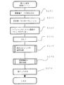
図1は、実施例であるデジタル画像への電子透かしの埋め込み方法とその処理原理の説明図である。原画像の画像データはデジタル情報として保存されており、図示するように、原画像に対して、8×8画素を一つの単位とするブロックを想定する。これはJPEGなどの画像圧縮などで広く用いられている手法と同じである。この例ではブロックの大きさは8×8画素としているが、必ずしもこの大きさに限定されるものではなく、他の大きさであっても差し支えない。
【0020】
次にこの原画像データに対して色変換の処理を行なう。この色変換の処理は必ずしも必要ないが、通常コンピュータ上で扱われる画像データは、RGB形式であり、これをその後の処理の都合に合わせて、色差信号系YCrCbなどの形式に変換するのである。これはカラー画像の場合であり、原画像がモノトーンの場合には、輝度信号のみを扱うことになるので、色変換などの処理は必要ない。また、データ処理の効率にこだわらなければ、原画像の形式のまま扱うことも可能である。
【0021】
この例では、カラー画像をYCrCb形式に変換し、このうちの輝度信号を示すYプレーンについて、直交変換を行なう。この例で、直交変換として、離散コサイン変換(以下、DCTと呼ぶ)を行なっているが、他の変換でも採用可能である。このDCTは、先に想定した8×8画素を単位とするブロック毎に行なわれる。通常、DCTにより得られたDCT係数(8×8)に対して、これを量子化テーブルとして用意した係数(量子化レベル)で除すことにより、量子化されたDCT係数(8×8)を得る。量子化テーブルで除算するのは、データを圧縮するためであり、電子透かしの埋め込みのために原理的に必要になるものではない。また、量子化テーブルの作り方により、量子化の粗さを設定できるが、電子透かしの埋め込みにより画質があれることは必ずしも望ましくないので、量子化テーブルを用いる場合には、画質の低下が小さい(圧縮率の低い)テーブルを採用することも望ましい。
【0022】
こうして8×8画素を1ブロックとして、DCTが行なわれ、量子化されたDCT係数が得られる。次に、隣接した二つのブロックについて得られたこのDCT係数を比較することにより、ビット情報を埋め込む処理を行なう。DCT係数が比較される二つのブロックは、処理の単純さと原画像の連続性という観点から、通常は隣接したブロックが選択されるが、必ずしも隣接したブロックに限定されるものではなく、また横方向に隣接するブロックに代えて、縦方向に隣接するブロックを採用することも差し支えない。また、3以上のブロックのDCT係数を利用してビット情報を埋め込むものとすることも可能である。ここで埋め込まれるビット情報は、予め基本パターンを生成しておき、この基本パターンから求められる。ビット情報の元になる基本パターンの生成方法とビット情報の埋込の詳細については後述する。
【0023】
こうしてビット情報が埋め込まれた各ブロックに対して、次に逆離散コサイン変換(以下、IDCTと呼ぶ)を行なう。このとき、DCTに用いたのと同一の量子化テーブルを利用する。逆変換により元の色差信号系YCrCbの画像データに変換される。なお、量子化テーブルを用いれば、通常は画像データの高周波成分が一部失われ、画質は劣化する。その後、逆色変換を行ない、元のRGB系の画像に戻すことができる。こうして基本パターンを透かし電子透かしとし、これが埋め込まれた画像を得ることができる。
【0024】
以上の説明では、画像は、元の形式(ここではRGB表色系)に戻したが、必ずしも元の形式に戻す必要はなく、例えばJPEGなどの形式で保存したままにしても良い。つまり、画像をJPEGなどの形式で保存する際に、予め用意した透かし情報に対応した基本パターンを埋め込むものとしても良い。
【0025】
こうして得られた画像データから、透かし情報を読み出す手法は、上記の手続を逆に辿ることになる。即ち、まず画像データから二つのブロックについての量子化されたDCT係数を求め、両係数の関係を調べて、ここに埋め込まれたビット情報を取り出し、これを配列することにより、基本パターンを復元するのである。この手法についても、後で詳しく説明する。
【0026】
<装置の全体構成>
次に、実施例において用いた装置構成につい簡単に説明する。図2は、実施例としての電子透かし埋め込み方法を実施する電子透かし埋め込み装置10のハードウェア構成を示すブロック図である。図示するように、この電子透かし埋め込み装置10は、コンピュータ20と、これに接続されたスキャナ12,CD−ROM等の外部記憶装置14,モデム16および表示用のモニタ18から構成されている。コンピュータ20は、処理を実行するCPU22と、モニタプログラムなどを記憶したROM23と、プログラムがロードされたり演算中のデータ等が一時的に記憶されたりするRAM24と、モニタ18に画像を表示するためのフレームメモリ25と、外部記憶装置14とのデータのやり取りを司るコントローラ(HDC)26と、モデム16とのデータのやり取りを司るシリアル入出力回路(SIO)28と、スキャナ12から画像を読み込む入力インタフェイス(入力IF)29等から構成されている。コンピュータには、キーボードやマウスなども接続されているが、これらの図示は省略した。モデム16は、通信回線NTを介してコンピュータネットワークに接続されている。コンピュータ20は、このモデム16を介して、コンピュータネットワークの図示しないサーバから、画像処理プログラムをダウンロードすることも可能である。また、このネットワークを介して、電子透かしを埋め込んだ画像データを、配信するといったことも可能である。
【0027】
CPU22は、RAM24上にロードされたプログラムを実行することにより、ブロック切出部31、変換部32、ビット情報埋込部33、出力部34等の機能を実現している。これら各部は、請求項のブロック切出手段、変換手段、ビット情報埋込手段、出力手段にそれぞれ対応しているが、各部の機能については、CPU22が実行する処理として後でまとめて説明する。
【0028】
次に、電子透かしの埋め込み方法について説明する。画像データに電子透かしを埋め込む前に、まず埋め込もうとする透かしパターンを生成する。図3は、この透かしパターンの生成処理ルーチンを示す説明図である。このルーチンを起動すると、まず著作権情報を入力し、これを10進数に展開する処理を行なう(ステップS50)。ここで著作権情報とは、埋め込もうとしている画像の権利者を示す情報であり、この実施例では、一人の著作者に対して一つのコード情報を設定するものとしている。一つの作品について一つのコードを割り当てても差し支えない。
【0029】
著作者毎に固有の10進数を展開する処理は、コンピュータ20内で自動的に実行するものとしてもよい、著作者が自ら所望のコードを入力するものとしても良い。なお、著作者情報の一元的な管理という点からは、例えば著作者名をコンピュータ20に入力すると、モデム16を介して著作権処理センターといった総括的な管理センターに必要な情報を送信し、このセンターから、著作者毎あるいは作品毎に固有のコードの配信を受けるものとしても良い。
【0030】
次に、こうして得られた10進数に基づいて、基本パターンを生成する処理を行なう(ステップS60)。本実施例では、電子透かしを単純にビット情報として埋め込むのではなく、これをあるパターンにして埋め込んでいる。ここでは、濃度パターン法(特に中村の方法)を採用して、10進数から基本パターンを生成している。透かし情報を文字や数字ビット系列として画像にそのままの姿で埋め込むと、冗長性がないため攻撃を受けた場合に復号誤りが多くなる。それを防ぐために透かしに誤り訂正符号などを適用する対応策もあるが、ここではパターンの冗長性を利用しているのである。
【0031】
基本パターンは、次のようにして生成される。まず、所定の大きさn(この例では図4に示すように4×4、即ちn=4)からなる2値図形にどの程度の情報を載せることができるかという点について説明する。図4に示す4×4の例では、基本パターンは、16個の透かし信号s(u)、(u=0,1,・・・15)から構成されている。画信号s(u)は、0または1の値をとる2値データである。また、s(u)=1の個数をmで表す。ただし、このmは、2値パターンを、m−out−of−n2 の冗長符号系を用いてデータを対応づけるために導入する。このとき、埋め込む透かし信号S上のn2 個の各要素を、組合せの数で重み付けられた2進数とみなし、
n2 Πm=n2-1Πm-1+n2-1Πm …(1)
の関係を用いれば、再帰的にs(u)の各要素の値を決定することができる。なお、ここで、式「aΠb」は、a個の要素からb個の要素を取りだす場合の組み合わせの数を表わすものとする(以下同じ)。
【0032】
まずu=0の場合を考えると、式(1)の右辺の第1項はs(0)←1となる配列の総数を、第2項はs(0)←0となる配列の総数を、それぞれ表している。したがって、s(0)=1である配列を、それぞれ
{0,1,2・・・m2-1Πm-1}
の各整数に、s(0)=0である配列をそれぞれ
{n2-1Πm-1,n2-1Πm-1+1,・・・m2Πm−1}
の各整数に対応させることができる。この規則を用い、
bm =log2(n2Πm)
の著作権管理情報t(10進数)と、n2-1Πm-1を比較して
t<n2-1Πm-1であれば、s(u)←1
t<n2-1Πm-1でなければ、s(u)←0
とする。
【0033】
仮にs(0)=1であれば、s(0)以外のs(u)(u=1,2,・・n2 −1)に残るm−1個の信号1を配置するために、mの値を1だけ減らして、更にtとn2-2Πm-1とを比較する。逆に、s(0)=0であれば、s(0)以外のs(u)(u=1,2,・・n2 −1)に残るm個の信号1を配置するため、tの値をn2-1Πm-1だけ減らして、更にtとn2-2Πm-1とを比較する。この操作を、m=0となるまで繰り返す。この手順により、基本パターン中で値1とする位置はすべて決定されるので、残りのs(u)には値0を埋める。以上の手順により、与えられたmとtとに一対一に対応する透かしパターンSを求めることができる。
【0034】
図5に、この手順で表現可能な基本パターンSの種類数を示した。mを値7ないし9とすれば、1個の基本パターンで13ビット分の10進数整数tを表現可能であることが了解される。この実施例で用いた濃度パターンのように、冗長性の高いパターンを利用している場合には、この冗長性を生かした誤り検出などの他の処理を組み込むことが可能となる。濃度パターンの場合、同じ濃度となるパターンは複数存在する。したがって、同じ濃度のパターンを用いる場合でも、その中でオン(黒)にするビットの配置は高い自由度で設定することができる。そこで、例えば同じ濃度でありながら、1ラスタ分の画素(x方向の総画素)中のオン(黒)画素の数を予め偶数個に決めておくといった使い方が可能となる。また、画質への影響を配慮して、どのパターンを用いるかを決定するといった使い方も可能である。本実施例では、上述したように、10進数を表現可能な大きさの濃度パターンを用いているが、このように、tの値がm−out−of−n2 の冗長システムとして表現可能な範囲にあれば、1個の基本パターンで十分である。管理すべき著作者情報がこの範囲を超える場合には、以上の基本パターンを2以上に分けて埋め込むものとすればよい。
【0035】
本実施例では、10進数を表現可能なので、図3のステップS60では、ステップS50で得られた10進数に対応づけて、上記の基本パターンのうちの一つを選択し、これを生成するのである。続いて、この基本パターンを、画像の全域に拡大し、透かしパターンを生成する処理を行なう(ステップS70)。この処理は次のように行なう。
【0036】
透かしパターンを埋め込もうとしている原画像Pが仮に256画素×256画素からなるとする。このとき原画像Pの中に8×8画素のブロックBuは32×32個存在する。これらのブロックのうち隣接するBu,Bu+1を一組とすると、この組みは32×16組存在することになる。この各組にs(u)を1ビットずつ写像しているので原画像Pの中には、4×4の基本パターンが8×4領域分、確保されたことになる。もし、著作権管理情報を表現できる透かし基本パターンが1個で十分ならば、画像Pの内部に透かし情報Sを、横方向に4回、縦方向に8回、合計32回重複して記録できることになる。このように、基本パターンを繰り返して透かしパターンとしているのは、透かしパターンの冗長性を高めて、透かしを埋め込んだ画像データに対するラプラシアン攻撃や一部の切り抜き利用に対して強い耐性を実現するためである。なお、著作権管理情報が多いために、基本パターンSが2個以上必要な場合には、たがいに識別可能なようにmの値を変更した基本パターンSを2個以上を作成し、画像が切り取られる可能性を考慮して、8×4個の領域に複数個の基本パターンSをランダムに配分するとよい。このようにすれば、10進数だけでなく、文字や文字列を埋め込むことも可能である。もとより、より大きな画像については、基本パターンの繰り返し回数を大きくし、かつ著作権管理情報を示す詳しい文字情報などを埋め込むことも可能である。
【0037】
以上で透かしパターンが生成されたことになる。そこで、次にこの透かしパターンを画像データに埋め込む手法について、詳しく説明する。図6は、透かし埋め込み処理の概要を示すフローチャートである。図示するように、この処理が開始されると、まず原画像データを読み込む処理を行なう(ステップS100)。次に読み込んだ原画像データを色変換する処理を行なう(ステップS110)。既に説明したように、この処理は、コンピュータ20上で画像を扱う一般的な信号系であるRGBの信号を、色差信号系であるYCrCbの形式に変更する処理である。原画像がカラー信号であれば、この処理により、輝度信号Y、色差信号Cr,Cbの3つのプレーンに分割された画像データが得られる。
【0038】
この3つのプレーンのうち、輝度信号に相当すYプレーンから8×8画素を単位とするブロックを切り出す処理を行なう(ステップS120)。原画像が例えば256×256画素からなる場合、その左上隅を原点として、水平方向xに順に32個のブロックを切り出し、端に至ると、垂直方向yにずらして次の32個のブロックを切り出し、この処理を32回繰り返すことで、32×32個のブロックを原画像から切り出すのである。こうして切り出したYプレーンの各ブロックについて、離散コサイン変換(DCT)を行なう。DCTの詳細は、周知のものなのでここでは説明しない。本実施例で、JPEGの輝度成分用の量子化テーブルを用いてDCT係数を量子化した。
【0039】
次に、先に設定した透かしパターンの基本パターンに従って決定したビット情報を、このブロックのDCT係数に埋め込む処理を行なう(ステップS150)。この処理については、後で図7を用いて説明する。ビット情報の埋め込みを行なった後、32×32個のブロックに対して、今度は逆離散コサイン変換(IDCT)を行ない(ステップS170)、更に逆色変換を行ない(ステップS180)、もとのRGB系の画像データに戻してから、画像を外部に出力する処理を行なう(ステップS190)。画像の出力は、カラープリンタ等を用いて印刷しても良いし、モデム16を用いてネットワーク上の使用者に配信しても良い。なお、この実施例では、透かしパターンを埋め込んだ画像は、RGB形式に戻しているが、JPEG形式に圧縮したままで出力しても良い。
【0040】
次に、ビット情報埋込処理(ステップS150)の詳細について説明する。ビット情報埋込処理ルーチンでは、図7に示すように、この処理が起動されると、まずYブレーンの互いに隣接するu番目とu+1番目のブロックについてのDCT係数Di(u,v)とDi+1(u,v)を入力する(ステップS151)。次に、これを量子化テーブルを用いて除算し量子化を行ない、周波数係数領域Fを求め、このFの構成要素fu(i,j)、fu+1(i,j)を求める処理を行なう(ステップS152)。ここで、i,j=0,1,・・・・7である。続いて、同じアドレス(i,j)の係数の大きさの差の絶対値d(i,j)を求める処理を行なう(ステップS153)。
【0041】
次に、鍵情報Kを決定する処理を行なう(ステップS154)。鍵情報Kは、以下に説明するビット情報の埋め込みにおいて、埋め込みのルールを秘匿するためのものであり、予めK={k(i,j)|i,j=0,1,2,・・・7}として与えられ、秘密にされるものである。尚、この実施例では、k(i,j)は、値0または1を取るものとしてある。
【0042】
次に埋め込もうとしているビット情報s(u)を、透かしパターンSから抽出する処理を行なう(ステップS155)。ビット情報は、この実施例では、隣接する二つのブロックでただ一つである。先に説明した透かしパターン(図3参照)から、順次どのブロックの組にどのビット情報を埋め込むかが決定される。更に、論理変数Dを演算する処理を行なう(ステップS156)。論理変数Dは、以下の条件により決定される。即ち、d(i,j)が値a以上あればD=1とし、d(i,j)が値a未満であればD=0とするのである。なお、この値aは、透かしの耐性強度を示す値であり、一般に大きいほど、外部からの攻撃に対して透かしは強い耐性を示す。しかし、あまり大きな値となれば、画質に影響を与えやすくなる。
【0043】
以上で、二つのブロックについて、その量子化されたDCT係数の差の絶対値に基づく論理変数Dと、鍵情報Kと、埋め込もうとしているビット情報s(u)とが決定されたことになる。そこで、次にこれらに3つの情報から、出力論理関数E1を演算する(ステップS161)。この出力論理関数E1は、論理テーブルとして示せば、図8のようになるが、論理式としては、
E1=S\・D\・K\+S・D\・K
である。なお、符号「\」は直前の変数が負論理であることを示している。
【0044】
出力論理関数E1が値1であるか否かを判断し(ステップS162)、E1=1でなければ何も行なわず、E1=1であれば、ステップS163において、係数fu(i,j)とfu+1(i,j)の大きい方に、所定値e(i,j)を加える処理を行なう。なお、この所定値e(i,j)は、通常、上述した透かしの耐性強度を示す値aに等しく設定される。
【0045】
次に、出力論理関数E2を演算する処理を行なう(ステップS165)。これは、図8の欄E2を求めることに等しく、その論理式は、
E2=S\・D・K+S・D・K\
である。その後、出力論理関数E1と同様、その値が1であるか否かを判別し(ステップS166)、値1であれば、ステップS167において、係数fu(i,j)とfu+1(i,j)の大きい方から、所定値e(i,j)を減算する処理を行なう。その後、以上の処理を、原画像の総てのブロックについて行なったか否かを判断し(ステップS169)、総てのブロックについて完了するまで繰り返す。原画像が256×256画素の画像である場合、2つの隣接するブロックを組として上記の処理を行なうので、32×16回の処理が繰り返されることになる。この処理の過程において、4×4の基本パターンが、4×8回繰り返し埋め込まれることは、既に説明した通りである。
【0046】
以上、原理図である図1、透かしパターンの埋め込み処理の概要を示す図6、ビット情報埋込処理ルーチンの詳細を示す図7を用いて説明したように、本実施例によれば、所定の関係(実施例ではx方向の隣接関係)を有する二つのブロックの離散コサイン変換(DCT)され量子化された係数を用いて、この係数の大きさに所定の差があるとき、これにビット情報s(u)を、鍵情報Kを参照しつつ、埋め込んでいる。即ち、この方法によれば、ブロックの組の量子化された係数を使って、1ビットの透かし信号s(u)を周波数領域の要素対fu(i,j)、fu+1(i,j)の差分値として冗長性を持たせて埋め込んでいるのである。しかも、透かしパターンを基本パターンの繰り返しとして構成し、いわば透かし情報を2重構造としているので、豊富な冗長性を導入することが可能となっている。したがって、切り取りやラプラシアン攻撃に対する強い耐性を示す。また、この耐性強度を、所定値e(i,j)により、容易に設定することができる。こうした攻撃に対する耐性は、末尾に、実験例として示した。なお、周波数領域の要素対fu(i,j)、fu+1(i,j)を変更していることから、画像は全周波数帯域にわたり微小な周波数成分の変動を受け、わずかながらその画質は劣化する。したがって、高品質の出力画像を必要とする場合には、強度パラメータe(i,j)=aの値を小さくするか、ビット情報の埋め込みにおいて、iおよびjが値0の係数、即ち直流成分や、更に一部の低周波成分を埋め込み対象から除外することも、画質を高く保つという点から好適である。この場合でも、もともとビット情報は、ブロックの多数の要素に埋め込んでいるので、i,j=0のいくつかの要素への埋め込みを行なわないものとしても、特に十分に透かしを復元することができる。
【0047】
なお、本実施例の鍵情報Kを用いることは、必ずしも必須ではないが、この実施例では、鍵情報Kを用いて、埋め込み規則の秘匿化を図っているので、画像を入手したものが、不正にこの埋め込み情報を抽出し、これを破壊するといったことを困難にしている。
【0048】
次に、画像に埋め込まれた透かしを復号する処理について説明する。図9は、透かし復号処理ルーチンを示すフローチャートである。また、図10は、埋め込みビットの復号処理の詳細を示すフローチャートである。両図は、透かしの埋め込み処理のフローチャートである図6および図7に対応しているので、簡略に説明する。
【0049】
このルーチンが起動されると、まず透かしを復号しようとする画像データを読み込み(ステップS200)、これを色変換する(ステップS210)。その上で、Yプレーンから8×8画素のブロックを切り出し(ステップS220)、これを離散コサイン変換(DCT)する(ステップS230)。こうして得られた量子化されたDCT係数から、埋め込みビットを復号する処理を行ない(ステップS250)、復号したビット情報から、透かしの基本パターンを復元する処理を行なう(ステップS270)。その後、復元した透かしを出力する(ステップS290)。
【0050】
ステップS250の埋め込みビットの復号処理は、図10に示したように、Yブレーンの隣接するブロックのDCT係数Di′(u,v)とDi+1′(u,v)を入力する(ステップS251)。次に、これを量子化テーブルを用いて除算し量子化を行ない、周波数係数領域F′を求め、このF′の構成要素fu′(i,j)、fu+1′(i,j)を求める処理を行なう(ステップS252)。続いて、同じアドレス(i,j)の係数の大きさの差の絶対値d′(i,j)を求める処理を行なう(ステップS253)。
【0051】
次に、鍵情報Kを決定する処理を行ない(ステップS254)、上記の絶対値d′(i,j)から、論理変数Dを求める処理を行なう(ステップS256)。論理変数Dは、以下の条件により決定される。即ち、d′(i,j)が値a以上あればD=1とし、d′(i,j)が値a未満であればD=0とするのである。
【0052】
以上で、二つのブロックについて、その量子化されたDCT係数の差の絶対値に基づく論理変数Dと、鍵情報Kとが求められたことになる。そこで、次にこれらに2つの情報から、出力論理関数EEを演算する(ステップS261)。この出力論理関数EEは、論理テーブルとして示せば、図11のようになるが、論理式としては、
EE=D・K+D\・K\
である。
【0053】
出力論理関数EEが値1であるか否かを判断し(ステップS262)、EE=1であれば、変数gを値1だけインクリメントする処理(ステップS263)を、出力論理関数EE=1でなければ、変数zを値1だけインクリメントする処理(ステップS264)をそれぞれ行なう。その後、以上の処理を、原画像の総てのブロックについて行なったか否かを判断し(ステップS266)、総てのブロックについて完了するまで繰り返す。
【0054】
全ブロックについて、以上の処理が完了すると、次に、変数gとzとの大小関係を判断し、いわば多数決により、この二つのブロックに埋め込まれたビット情報s(u)を値1または値0に決定する(ステップS268,269)。
【0055】
以上の処理により、容易かつ安定に隣接する二つのブロックに埋め込まれたビット情報s(u)を取りだすことができる。そこで、u=0,1,2・・・・15に対応したビット情報s(u)がすべて求められ、電子透かしとしての基本パターンが確定したところで、著作権の管理情報を復号する処理について説明する。図12は、著作権管理情報の復号処理ルーチンを示すフローチャートである。図示するように、このルーチンが起動されると、まず、値1ないし16を取り得る変数x,yを用いて、その順列組み合わせの数xΠyを、配列M(x,y)に代入する処理を行なう(ステップS271)。次に、x,y,u,tに初期値を代入し(ステップS272)、以下の処理を開始する。
【0056】
ステップS273では、初期値として値mが代入された変数yが値0となっているかどうかを判断する。これは、探索が終了したかどうかを判断するためである。処理が開始された直後には、変数yの値は0とはなっていないので、処理はステップS274以下に進み、まずビット情報s(u)が値0か否かの判断が行なわれる。ビット情報s(u)が値0であれば、著作権の管理情報に対応した10進数に配列M(x,y−1)を加え(ステップS275)、s(u)=0でなければ変数yを値1だけデクリメントする処理を行なう(ステップS276)。いずれの場合も、その後、変数xを値1だけデクリメントし、変数uを値1だけインクリメントする処理を行なう(ステップS278)。
【0057】
その後、変数uが値15より大きくなったか否かを判断し(ステップS279)、大きくなっていれば、変数yが値0となった場合と共に、ステップS280に移行して、管理情報tの下位ビットを、log2 M(16,j)として復号する処理を行なう。以上説明した手順により透かしの基本パターンに埋め込まれていた数値データ、即ち著作権などの管理情報tを復号することができる。本実施例の方法で埋め込まれた透かしは、基本パターンとされ、更にこれを複数回埋め込んだ2重構造とされていることから、豊富な冗長性を導入することが可能となったており、容易かつ安定に、この透かしを復号することができる。
【0058】
次にこの方法を用いた実験結果を示す。上述した実施例に従って、著作権管理情報を埋め込んだ。この実験では、著作権管理情報Tとしてt=123(10進数)を用いた。この値tを表現するのに、図5に示した結果を勘案し、m=3を利用した。上述した実施例の手法により基本パターン作成を求めた結果を、図13に示した。この基本パターンを、図3に示したように、2ブロックに1個の割合いで256×256の領域に繰り返し配列した場合の透かしパターンを、図14に示した。この2値画像を透かし情報として濃淡画像PのDCTされた周波数係数領域に埋め込んだ。その結果を図15に示す。この透かしを埋め込んだ画像P′に対してラプラシアン攻撃を加えた結果を、図16に示した。この画像から透かし情報を復号した結果を、図17示した。図示するように、ラプラシアン攻撃に対しても、元の透かしパターンは大部分保存されていることがわかる。また、一部のパターンは失われているが、多数決原理などを用いることにより、この繰り返しパターンから、元の基本パターンを正確に復元することは容易であった。
【0059】
以上、本発明の実施例と、その実験結果について説明したが、このブロック切出部31,変換部32,ビット情報埋込部33,出力部34などの機能を実現するコンピュータプログラムは、フレキシブルディスクやCD−ROM等の、コンピュータ読み取り可能な記録媒体に記録された形態で提供される。コンピュータは、その記録媒体からコンピュータプログラムを読み取って内部記憶装置または外部記憶装置に転送する。あるいは、通信経路を介してコンピュータにコンピュータプログラムを供給するようにしてもよい。コンピュータプログラムの機能を実現する時には、内部記憶装置に格納されたコンピュータプログラムがコンピュータのマイクロプロセッサによって実行される。また、記録媒体に記録されたコンピュータプログラムをコンピュータが読み取って直接実行するようにしてもよい。
【0060】
この明細書において、コンピュータとは、ハードウェア装置とオペレーションシステムとを含む概念であり、オペレーションシステムの制御の下で動作するハードウェア装置を意味している。また、オペレーションシステムが不要でアプリケーションプログラム単独でハードウェア装置を動作させるような場合には、そのハードウェア装置自体がコンピュータに相当する。ハードウェア装置は、CPU等のマイクロプロセッサと、記録媒体に記録されたコンピュータプログラムを読み取るための手段とを少なくとも備えている。コンピュータプログラムは、このようなコンピュータに、上述の各手段の機能を実現させるプログラムコードを含んでいる。なお、上述の機能の一部は、アプリケーションプログラムでなく、オペレーションシステムによって実現されていても良い。更に、電子透かしの埋め込み処理や復号処理を行なうプログラムは、画像処理を行なうプログラムに対して、プラグインの形式で付加されるものとしてもよい。
【0061】
なお、この発明における「記録媒体」としては、フレキシブルディスクやCD−ROM、光磁気ディスク、ICカード、ROMカートリッジ、パンチカード、バーコードなどの符号が印刷された印刷物、コンピュータの内部記憶装置(RAMやROMなどのメモリ)および外部記憶装置等の、コンピュータが読取り可能な種々の媒体を利用することができる。
【0062】
以上本発明の実施例について説明したが、本発明はこうした実施例に何等限定されるものではなく、種々なる態様で実施し得ることは勿論である。
【図面の簡単な説明】
【図1】本発明の一実施例である電子透かし情報の埋め込みおよび復号処理の原理説明図である。
【図2】実施例としての電子透かし埋め込み装置10の構成例を示すブロック図である。
【図3】透かしパターン生成処理ルーチンを示すフローチャートである。
【図4】埋め込まれる透かしパターンについて説明する説明図である。
【図5】パターンにより表現可能な情報の種類を示す説明図である。
【図6】電子透かし復号処理の概要を説明するフローチャートである。
【図7】ビット情報埋込処理ルーチンを示すフローチャートである。
【図8】埋め込むビット情報sと、論理変数Dと、鍵情報Kとから、出力論理関数E1,E2を求めるテーブルを示す説明図である。
【図9】透かし復号処理ルーチンを示すフローチャートである。
【図10】埋め込みビット復号処理ルーチンを示すフローチャートである。
【図11】復号用の出力論理関数EEを求めるためのテーブルを示す説明図である。
【図12】著作権管理情報の復号処理ルーチンを示すフローチャートである。
【図13】実験例で用いた基本パターンを示す説明図である。
【図14】実験例で用いた繰り返しパターンの一例を示す説明図である。
【図15】実験例としての透かしパターンを埋め込んだ画像の一例を示す説明図である。
【図16】ラプラシアン攻撃された後の画像データを示す説明図である。
【図17】ラプラシアン攻撃された後の画像データから復号された透かしパターンの一例を示す説明図である。
【符号の説明】
10…電子透かし埋め込み装置
12…スキャナ
14…外部記憶装置
16…モデム
18…モニタ
20…コンピュータ
22…CPU
23…ROM
24…RAM
24…メインメモリ
25…フレームメモリ
26…HDC
28…SIO
29…入力IF
31…ブロック切出部
32…変換部
33…ビット情報埋込部
34…出力部[0001]
BACKGROUND OF THE INVENTION
The present invention relates to a method for embedding a digital watermark in two-dimensional data such as an image, a decoding method for decoding the embedded digital watermark, and an apparatus for performing the method.
[0002]
[Prior art]
With the development of computer networks such as the Internet, information has been digitized, and many users can easily access necessary information. On the other hand, it is becoming an environment where data can be easily duplicated without permission from the author of the digital content for which copyright is generated in the digital information, and the problem of copyright infringement due to unauthorized copying has been attracting attention. ing. Therefore, for the purpose of preventing copyright infringement regarding color images, which are the main information of digital contents, copyright information is secretly embedded in color image data invisible to a third party, A technique that can extract right information, a so-called digital watermark technique, has attracted attention.
[0003]
As a method for embedding a digital watermark in two-dimensional data such as an image, for example, a method is known in which orthogonal transformation such as discrete cosine transformation is performed on image data, and the obtained coefficient is changed by a predetermined algorithm. Yes. In this case, the original image is kept secret, the original image and the image considered to be copied are orthogonally transformed in the same manner, and the coefficients are compared to verify the coincidence between them.
[0004]
[Problems to be solved by the invention]
However, this method requires a secret original image to extract copyright information, and invites a new problem of managing the original image. As the number of original images increases, its management becomes increasingly difficult. Therefore, it is desirable to embed the digital watermark in a form that can be directly extracted from the image as much as possible.
[0005]
On the other hand, for such a digital watermark, it is necessary to evaluate whether or not it can withstand a part of an image or an overwrite attack. In recent years, various attack methods such as a Laplacian attack have been clarified for digital watermarking using orthogonal transformation. When more information is embedded on the image side, no method has been proposed that has sufficient effectiveness against such problems as attacks and partial use of images.
[0006]
An object of the present invention is to solve the above-mentioned problems related to embedding and decoding of a digital watermark using orthogonal transformation, and to propose a technique for embedding and decoding a digital watermark having sufficient resistance against various attacks. And
[0007]
[Means for solving the problems and their functions and effects]
The present invention is a method for embedding digital watermark information in an image, comprising:
Cut out a block of a certain size from the original image,
Perform orthogonal transformation on the image data corresponding to each block,
The coefficient after the orthogonal transformation is quantized using a quantization table.
Adjacent to each other on the imageTwo or more blocks of saidAfter quantizationCompare the corresponding coefficients ofIf the corresponding coefficients of both blocks after quantization are not the
Outputs an image with an embedded digital watermark by performing inverse orthogonal transform on the block in which the bit information is embedded.
This is the gist.
[0008]
According to this digital watermark embedding method, two or more blocks having a predetermined relationship are used, the coefficients after orthogonal transformation of these blocks are compared, and bit information is obtained using the magnitude relationship of both coefficients. Embedded. Therefore, the digital watermark can be extracted from the image at any time if the block relationship and the magnitude relationship between the coefficients are known, and the digital watermark cannot be extracted unless the size relationship is known. Therefore, it is possible to realize a digital watermark embedding method that is easy to handle and resistant to attacks. Of course, it is possible to conceal the original image in which the digital watermark is embedded and to confirm the digital watermark by comparison with the original image.
[0009]
On the other hand, the invention of a decoding method for extracting a digital watermark from image data in which the digital watermark is embedded is as follows:
Cut out a block of a certain size from the original image,
Perform orthogonal transformation on the image data corresponding to each block,
The coefficient after the orthogonal transformation is quantized using a quantization table.
Adjacent to each other on the imageTwo or more blocks of saidAfter quantizationCompare the corresponding coefficients ofIf the corresponding coefficients of both blocks after quantization are not the
This is the gist.
According to this digital watermark decoding method, the digital watermark can be easily extracted.
[0010]
Various implementations are possible based on this principle. For example, adjacent blocks can be used as the blocks having a predetermined relationship. In an image, there is often a predetermined correlation between adjacent images, so that a certain tendency may occur in the magnitude relationship of coefficients between blocks, which may be suitable for embedding a digital watermark according to the present invention. is there.
[0011]
Also, discrete cosine transform can be used as orthogonal transform for image data. This is because the discrete cosine transform is also employed in JPEG and exhibits excellent characteristics for image compression and the like. It is also preferable to quantize the coefficient after orthogonal transformation using a quantization table and embed the information bits using the quantized coefficient. This is because the compression efficiency can be freely varied by adjusting the quantum table.
[0012]
As an example of such image conversion, image data is converted into luminance Y and color differences Cb and Cr prior to the orthogonal transformation, and discrete cosine is used as the orthogonal transformation for each of the luminance Y and color differences Cb and Cr. A configuration can be considered in which the bit information is embedded in a coefficient obtained by performing transformation and performing discrete cosine transformation on the luminance Y.
[0013]
It is also desirable to embed bit information when the corresponding coefficients of both blocks after quantization are not 0. This is because if both blocks have a value of 0 and bit information is embedded and the coefficient is changed to a value other than 0, the data compression efficiency may decrease.
[0014]
In the digital watermark embedding described above, it is also possible to introduce a logical function that is true when the difference between coefficients after orthogonal transformation of two or more blocks having the predetermined relationship is within a predetermined range, thereby simplifying the calculation. This is preferable. In this case, the bit information embedding method may be changed based on the truth of the logical function. It becomes easy to vary the predetermined range.
[0015]
Furthermore, in this digital watermark embedding method,
Prepare in advance a secret key associated with the coefficient obtained by orthogonal transformation,
It is also preferable to change the method of embedding the bit information based on the secret key for each coefficient and the true / false state of the logical function for the coefficient. In this case, if there is no secret key, it is extremely difficult to specify by what rule the bit information is embedded. Usually, such a secret key may be managed for each image, but can also be managed for each author, and digital watermark management becomes easy.
[0016]
Here, a basic pattern two-dimensionally defined as a combination of binary information is prepared as digital watermark information, and each binary information constituting the basic pattern is set as bit information to be embedded, and has a predetermined relationship. It is also useful to embed the binary information constituting this basic pattern with a certain block as one unit. In this case, the electronic watermark is embedded as a two-dimensionally defined basic pattern, and this basic pattern can be directly used as copyright information or the like. As such a basic pattern, it is preferable to use a pattern having redundancy. This is because error detection can be performed by utilizing the redundancy of the pattern. Applications such as changing the bit information of the basic pattern used for the digital watermark according to the nature of the image to be embedded with the digital watermark are also possible. The basic pattern having such redundancy can be determined using, for example, a density pattern method. The density pattern is based on the principle that there are a plurality of dot arrangements where the density is equal considering an n × n pixel region, and has high redundancy. Therefore, if the density pattern is used, error detection and the like can be realized by taking advantage of its high redundancy.
[0017]
Further, when the number of elements constituting the basic pattern is sufficiently larger than the number of cut out blocks, the basic pattern can be repeatedly embedded in the image data a predetermined number of times. In this way, even if a part of the image is cut out, the basic pattern can be decoded, and the resistance of the digital watermark can be improved.
[0018]
The above-described digital watermark embedding method and digital watermark decoding method can be implemented as a storage medium storing the same. As such a storage medium, forms such as a CD-ROM, a memory card, and a flexible disk can be considered. Also, a form of downloading these programs via a communication line can be considered. Furthermore, such a method for embedding a digital watermark can be incorporated into retouching software that handles image data or as plug-in software. Of course, it may be realized as an independent program that only embeds and decodes a digital watermark. Furthermore, considering the form in which color images are distributed as digital contents, they are often compressed using various compression techniques such as JPEG, so they are incorporated into software that compresses image data in the form of a single or plug-in. There is no problem. Alternatively, it may be integrated into a scanner that reads printed image data as digital data or reading software. On the other hand, it can be used by being incorporated in a printer driver or printer that prints digital data. Further, these embedding method and decoding method can be easily realized as a device. In this case, it can be realized as a dedicated device, or by reading a program from the recording medium, the computer can be used as an electronic watermark embedding device or a decoding device.
[0019]
DETAILED DESCRIPTION OF THE INVENTION
Hereinafter, preferred embodiments of the present invention will be described.
<Principle of digital watermark embedding and decoding>
FIG. 1 is an explanatory diagram of a method for embedding a digital watermark in a digital image according to an embodiment and a processing principle thereof. The image data of the original image is stored as digital information, and as illustrated, a block having 8 × 8 pixels as one unit is assumed for the original image. This is the same technique widely used in image compression such as JPEG. In this example, the size of the block is 8 × 8 pixels, but the size is not necessarily limited to this size, and other sizes may be used.
[0020]
Next, color conversion processing is performed on the original image data. Although this color conversion process is not necessarily required, the image data normally handled on a computer is in the RGB format, and is converted into a format such as a color difference signal system YCrCb in accordance with the convenience of subsequent processing. This is a case of a color image, and when the original image is monotone, only a luminance signal is handled, so that processing such as color conversion is not necessary. If the efficiency of data processing is not concerned, the original image format can be handled.
[0021]
In this example, a color image is converted into the YCrCb format, and orthogonal conversion is performed on the Y plane indicating the luminance signal. In this example, discrete cosine transform (hereinafter referred to as DCT) is performed as orthogonal transform, but other transforms can be employed. This DCT is performed for each block having a unit of 8 × 8 pixels assumed previously. Usually, the DCT coefficient (8 × 8) obtained by DCT is divided by a coefficient (quantization level) prepared as a quantization table to obtain a quantized DCT coefficient (8 × 8). obtain. The division by the quantization table is to compress data, and is not necessary in principle for embedding a digital watermark. In addition, the roughness of the quantization can be set depending on how the quantization table is created, but it is not always desirable that the image quality is improved by embedding the digital watermark. Therefore, when the quantization table is used, the degradation in image quality is small ( It is also desirable to employ a table with a low compression rate.
[0022]
Thus, DCT is performed with 8 × 8 pixels as one block, and quantized DCT coefficients are obtained. Next, the bit information is embedded by comparing the DCT coefficients obtained for two adjacent blocks. The two blocks to be compared with the DCT coefficient are usually selected from the viewpoint of simplicity of processing and continuity of the original image, but are not necessarily limited to the adjacent blocks, and are not limited to the horizontal direction. Instead of the blocks adjacent to each other, the blocks adjacent in the vertical direction may be adopted. It is also possible to embed bit information using DCT coefficients of three or more blocks. The bit information embedded here is obtained from a basic pattern generated in advance. Details of the generation method of the basic pattern that is the basis of the bit information and the embedding of the bit information will be described later.
[0023]
Next, inverse discrete cosine transform (hereinafter referred to as IDCT) is performed on each block in which the bit information is embedded. At this time, the same quantization table used for DCT is used. The original color difference signal system YCrCb image data is converted by inverse conversion. If a quantization table is used, usually a part of the high frequency component of the image data is lost and the image quality deteriorates. Thereafter, reverse color conversion can be performed to restore the original RGB image. In this way, it is possible to obtain an image in which the basic pattern is set as a watermark digital watermark and this is embedded.
[0024]
In the above description, the image is returned to the original format (here, the RGB color system), but it is not always necessary to return to the original format, and may be stored in a format such as JPEG, for example. That is, when an image is stored in a format such as JPEG, a basic pattern corresponding to watermark information prepared in advance may be embedded.
[0025]
The method of reading watermark information from the image data thus obtained follows the above procedure in reverse. That is, first, quantized DCT coefficients for two blocks are obtained from image data, the relationship between both coefficients is examined, bit information embedded therein is taken out, and this is arranged to restore the basic pattern. It is. This method will also be described in detail later.
[0026]
<Overall configuration of device>
Next, the apparatus configuration used in the examples will be briefly described. FIG. 2 is a block diagram illustrating a hardware configuration of the digital
[0027]
The
[0028]
Next, a digital watermark embedding method will be described. Before embedding a digital watermark in image data, a watermark pattern to be embedded is first generated. FIG. 3 is an explanatory diagram showing this watermark pattern generation processing routine. When this routine is started, copyright information is first input and a process of expanding the copyright information into a decimal number is performed (step S50). Here, the copyright information is information indicating the right holder of the image to be embedded. In this embodiment, one piece of code information is set for one author. One code can be assigned to one work.
[0029]
The process of developing a unique decimal number for each author may be automatically executed in the
[0030]
Next, a process of generating a basic pattern is performed based on the decimal number thus obtained (step S60). In this embodiment, the digital watermark is not simply embedded as bit information, but is embedded in a certain pattern. Here, a basic pattern is generated from a decimal number by employing a density pattern method (in particular, Nakamura's method). If the watermark information is embedded in the image as it is as a character or numeric bit sequence, there is no redundancy, so that there are many decoding errors when attacked. In order to prevent this, there is a countermeasure to apply an error correction code or the like to the watermark, but here the pattern redundancy is used.
[0031]
The basic pattern is generated as follows. First, how much information can be placed on a binary figure having a predetermined size n (in this example, 4 × 4, that is, n = 4 as shown in FIG. 4) will be described. In the 4 × 4 example shown in FIG. 4, the basic pattern is composed of 16 watermark signals s (u), (u = 0, 1,... 15). The image signal s (u) is binary data that takes a value of 0 or 1. The number of s (u) = 1 is represented by m. Where m is a binary pattern, m-out-of-n2This is introduced to associate data using the redundant code system. At this time, n on the watermark signal S to be embedded2Each element is considered a binary number weighted by the number of combinations,
n2Πm = n2-1Πm-1 + n2-1Πm (1)
Using the relationship, it is possible to recursively determine the value of each element of s (u). Here, the expression “aΠb” represents the number of combinations when b elements are extracted from a elements (the same applies hereinafter).
[0032]
First, considering the case of u = 0, the first term on the right side of Equation (1) is the total number of arrays where s (0) ← 1, and the second term is the total number of arrays where s (0) ← 0. , Respectively. Therefore, each array with s (0) = 1 is
{0,1,2, ... m2-1Πm-1}
For each integer, an array where s (0) = 0
{N2-1Πm-1, n2-1Πm-1 + 1, ... m2Πm-1}
Can correspond to each integer. Using this rule,
bm = log2(N2Πm)
Copyright management information t (decimal number) and n2Comparing -1Πm-1
t <n2If -1Πm-1, s (u) ← 1
t <n2If not -1) m-1, s (u) ← 0
And
[0033]
If s (0) = 1, s (u) other than s (0) (u = 1, 2,... N2In order to arrange m-1
[0034]
FIG. 5 shows the number of types of basic patterns S that can be expressed by this procedure. If m is a value from 7 to 9, it is understood that a decimal integer t for 13 bits can be expressed by one basic pattern. When a highly redundant pattern such as the density pattern used in this embodiment is used, other processes such as error detection utilizing this redundancy can be incorporated. In the case of the density pattern, there are a plurality of patterns having the same density. Therefore, even when patterns having the same density are used, the arrangement of bits to be turned on (black) can be set with a high degree of freedom. Therefore, for example, it is possible to use the number of ON (black) pixels in an even number of pixels in one raster pixel (total pixels in the x direction) with the same density. In addition, it is possible to use such as determining which pattern is used in consideration of the influence on the image quality. In the present embodiment, as described above, a density pattern having a size capable of expressing a decimal number is used. Thus, the value of t is m-out-of-n.2One basic pattern is sufficient if it can be expressed as a redundant system. When the author information to be managed exceeds this range, the above basic pattern may be embedded in two or more.
[0035]
Since decimal numbers can be expressed in this embodiment, in step S60 of FIG. 3, one of the above basic patterns is selected and generated in association with the decimal number obtained in step S50. is there. Subsequently, the basic pattern is enlarged over the entire area of the image, and a watermark pattern is generated (step S70). This process is performed as follows.
[0036]
Assume that the original image P to be embedded with a watermark pattern is composed of 256 pixels × 256 pixels. At this time, there are 32 × 32 blocks Bu of 8 × 8 pixels in the original image P. If adjacent Bu and Bu + 1 are one set among these blocks, there are 32 × 16 sets. Since s (u) is mapped bit by bit to each set, 4 × 4 basic patterns for 8 × 4 areas are secured in the original image P. If only one watermark basic pattern that can express copyright management information is sufficient, the watermark information S can be recorded inside the image P four times in the horizontal direction and eight times in the vertical direction, for a total of 32 times. become. In this way, the basic pattern is repeated to form a watermark pattern in order to increase the redundancy of the watermark pattern and to realize a strong resistance to Laplacian attacks and partial clipping of image data embedded with a watermark. is there. When there are two or more basic patterns S due to the large amount of copyright management information, two or more basic patterns S with different values of m are created so that the images can be identified. In consideration of the possibility of being cut out, a plurality of basic patterns S may be randomly distributed in 8 × 4 regions. In this way, not only decimal numbers but also characters and character strings can be embedded. Of course, for larger images, it is possible to increase the number of repetitions of the basic pattern and embed detailed character information indicating copyright management information.
[0037]
Thus, the watermark pattern is generated. A method for embedding this watermark pattern in the image data will be described in detail. FIG. 6 is a flowchart showing an outline of the watermark embedding process. As shown in the figure, when this process is started, first, a process of reading original image data is performed (step S100). Next, a process for color conversion of the read original image data is performed (step S110). As already described, this processing is processing for changing the RGB signal, which is a general signal system for handling images on the
[0038]
Of these three planes, a process of cutting out a block in units of 8 × 8 pixels from the Y plane corresponding to the luminance signal is performed (step S120). If the original image is composed of 256 × 256 pixels, for example, 32 blocks are cut out in order in the horizontal direction x with the upper left corner as the origin, and the next 32 blocks are cut out in the vertical direction y when reaching the end. By repeating this
[0039]
Next, a process of embedding bit information determined according to the basic pattern of the watermark pattern set previously in the DCT coefficient of this block is performed (step S150). This process will be described later with reference to FIG. After the bit information is embedded, the inverse discrete cosine transform (IDCT) is performed on the 32 × 32 blocks (step S170), and the inverse color transform is performed (step S180). After returning to the system image data, a process of outputting the image to the outside is performed (step S190). The image output may be printed using a color printer or the like, or distributed to users on the network using the modem 16. In this embodiment, the image in which the watermark pattern is embedded is returned to the RGB format, but may be output while being compressed to the JPEG format.
[0040]
Next, details of the bit information embedding process (step S150) will be described. In the bit information embedding processing routine, as shown in FIG. 7, when this processing is started, first, the DCT coefficients Di (u, v) for the u-th and u + 1-th blocks adjacent to each other in the Y-branes are set. Di + 1 (u, v) is input (step S151). Next, this is divided by using a quantization table, quantization is performed, a frequency coefficient region F is obtained, and processing for obtaining the components fu (i, j) and fu + 1 (i, j) of this F is performed. (Step S152). Here, i, j = 0, 1,... Subsequently, a process for obtaining an absolute value d (i, j) of the difference in the magnitude of the coefficient at the same address (i, j) is performed (step S153).
[0041]
Next, a process for determining the key information K is performed (step S154). The key information K is for concealing an embedding rule in embedding bit information described below, and K = {k (i, j) | i, j = 0,1,2,. It is given as 7} and kept secret. In this embodiment, k (i, j) takes a
[0042]
Next, the bit information s (u) to be embedded is extracted from the watermark pattern S (step S155). In this embodiment, the bit information is only one in two adjacent blocks. From the watermark pattern described above (see FIG. 3), it is determined which bit information is embedded in which block set sequentially. Further, a process for calculating the logical variable D is performed (step S156). The logical variable D is determined by the following conditions. That is, if d (i, j) is greater than or equal to value a, D = 1, and if d (i, j) is less than value a, D = 0. The value a is a value indicating the strength of the watermark. Generally, the larger the value a, the stronger the watermark is against an attack from the outside. However, if the value is too large, the image quality is likely to be affected.
[0043]
As described above, for the two blocks, the logical variable D based on the absolute value of the difference between the quantized DCT coefficients, the key information K, and the bit information s (u) to be embedded are determined. Become. Therefore, the output logic function E1 is calculated from these three pieces of information (step S161). If this output logical function E1 is shown as a logical table, it becomes as shown in FIG.
E1 = S \ · D \ · K \ + S · D \ · K
It is. The symbol “\” indicates that the immediately preceding variable is negative logic.
[0044]
It is determined whether or not the output logical function E1 is a value 1 (step S162). If E1 = 1, nothing is performed, and if E1 = 1, in step S163, the coefficient fu (i, j) is calculated. A process of adding a predetermined value e (i, j) to the larger of fu + 1 (i, j) is performed. Note that the predetermined value e (i, j) is normally set equal to the value a indicating the watermark tolerance strength described above.
[0045]
Next, a process for calculating the output logic function E2 is performed (step S165). This is equivalent to finding the column E2 in FIG.
E2 = S \ ・ D ・ K + S ・ D ・ K \
It is. Thereafter, similarly to the output logic function E1, it is determined whether or not the value is 1 (step S166). If the value is 1, the coefficient fu (i, j) and fu + 1 (i, i, j) are determined in step S167. A process of subtracting a predetermined value e (i, j) from the larger of j) is performed. Thereafter, it is determined whether or not the above processing has been performed for all blocks of the original image (step S169), and is repeated until completion for all blocks. When the original image is an image of 256 × 256 pixels, the above processing is performed with two adjacent blocks as a set, and thus the processing of 32 × 16 times is repeated. As described above, the 4 × 4 basic pattern is repeatedly embedded 4 × 8 times in the process.
[0046]
As described above with reference to FIG. 1, which is the principle diagram, FIG. 6 showing the outline of the watermark pattern embedding process, and FIG. 7 showing the details of the bit information embedding process routine, When a coefficient obtained by performing discrete cosine transform (DCT) and quantization of two blocks having a relationship (adjacent relationship in the x direction in the embodiment) is used and there is a predetermined difference in the magnitude of this coefficient, s (u) is embedded with reference to the key information K. That is, according to this method, a quantized coefficient of a block set is used to convert a 1-bit watermark signal s (u) into frequency domain element pairs fu (i, j), fu + 1 (i, j ) Is embedded with redundancy as a difference value. Moreover, since the watermark pattern is configured as a repetition of the basic pattern and the watermark information has a double structure, it is possible to introduce abundant redundancy. Therefore, it shows strong resistance against clipping and Laplacian attacks. Moreover, this tolerance strength can be easily set by the predetermined value e (i, j). The resistance to such attacks is shown as an experimental example at the end. Since the frequency domain element pairs fu (i, j) and fu + 1 (i, j) are changed, the image is subject to minute frequency component fluctuations over the entire frequency band, and its image quality is slightly. to degrade. Therefore, when a high-quality output image is required, the value of the intensity parameter e (i, j) = a is reduced, or in the bit information embedding, i and j are coefficients having a value of 0, that is, DC components. In addition, it is also preferable to exclude some of the low frequency components from the embedding target in terms of maintaining high image quality. Even in this case, since the bit information is originally embedded in many elements of the block, the watermark can be restored particularly sufficiently even if it is not embedded in some elements of i, j = 0. .
[0047]
It is not always necessary to use the key information K of the present embodiment, but in this embodiment, the embedding rule is concealed using the key information K. It is difficult to extract this embedded information illegally and destroy it.
[0048]
Next, a process for decoding a watermark embedded in an image will be described. FIG. 9 is a flowchart showing a watermark decoding processing routine. FIG. 10 is a flowchart showing details of the embedded bit decoding process. Both figures correspond to FIG. 6 and FIG. 7 which are flowcharts of the watermark embedding process, and will be described briefly.
[0049]
When this routine is started, first, image data to be decoded is read (step S200), and this is color-converted (step S210). Then, a block of 8 × 8 pixels is cut out from the Y plane (step S220), and this is subjected to discrete cosine transform (DCT) (step S230). A process of decoding embedded bits is performed from the quantized DCT coefficients thus obtained (step S250), and a process of restoring a watermark basic pattern from the decoded bit information is performed (step S270). Thereafter, the restored watermark is output (step S290).
[0050]
In the embedded bit decoding process in step S250, as shown in FIG. 10, the DCT coefficients Di ′ (u, v) and Di + 1 ′ (u, v) of the adjacent blocks of the Y brain are input (step S251). ). Next, this is divided by using the quantization table and quantization is performed to obtain the frequency coefficient region F ′, and the components fu ′ (i, j) and fu + 1 ′ (i, j) of this F ′ are determined. The requested process is performed (step S252). Subsequently, a process for obtaining an absolute value d ′ (i, j) of the difference in the coefficient size of the same address (i, j) is performed (step S253).
[0051]
Next, a process for determining the key information K is performed (step S254), and a process for obtaining the logical variable D from the absolute value d '(i, j) is performed (step S256). The logical variable D is determined by the following conditions. That is, if d '(i, j) is greater than or equal to the value a, D = 1, and if d' (i, j) is less than the value a, D = 0.
[0052]
Thus, the logical variable D based on the absolute value of the quantized DCT coefficient difference and the key information K are obtained for the two blocks. Therefore, the output logic function EE is calculated from these two pieces of information (step S261). If this output logic function EE is shown as a logic table, it becomes as shown in FIG.
EE = D ・ K + D \ ・ K \
It is.
[0053]
It is determined whether or not the output logic function EE has a value 1 (step S262). If EE = 1, the process of incrementing the variable g by the value 1 (step S263) must be the output logic function EE = 1. For example, the variable z is incremented by 1 (step S264). Thereafter, it is determined whether or not the above processing has been performed for all blocks of the original image (step S266), and is repeated until completion for all blocks.
[0054]
When the above processing is completed for all the blocks, next, the magnitude relationship between the variables g and z is determined. In other words, the bit information s (u) embedded in the two blocks is set to the
[0055]
Through the above processing, the bit information s (u) embedded in two adjacent blocks can be taken out easily and stably. Therefore, when all the bit information s (u) corresponding to u = 0, 1, 2,... 15 is obtained and the basic pattern as the digital watermark is determined, the process of decoding the copyright management information will be described. To do. FIG. 12 is a flowchart illustrating a copyright management information decryption processing routine. As shown in the figure, when this routine is started, first, a process of substituting the number xΠy of the permutation combinations into the array M (x, y) using variables x and y that can take
[0056]
In step S273, it is determined whether or not the variable y to which the value m is substituted as an initial value is a
[0057]
Thereafter, it is determined whether or not the variable u has become larger than the value 15 (step S279). If the variable u has become larger, the process proceeds to step S280 together with the case where the variable y has the
[0058]
Next, experimental results using this method are shown. In accordance with the embodiment described above, copyright management information was embedded. In this experiment, t = 123 (decimal number) was used as the copyright management information T. In order to express this value t, m = 3 was used in consideration of the result shown in FIG. The result of obtaining the basic pattern by the method of the above-described embodiment is shown in FIG. FIG. 14 shows a watermark pattern when this basic pattern is repeatedly arranged in an area of 256 × 256 at a rate of one for every two blocks as shown in FIG. This binary image was embedded as a watermark information in the frequency coefficient region obtained by DCT of the grayscale image P. The result is shown in FIG. FIG. 16 shows the result of applying a Laplacian attack to the image P ′ in which this watermark is embedded. The result of decoding the watermark information from this image is shown in FIG. As shown in the figure, it can be seen that the original watermark pattern is mostly preserved against the Laplacian attack. Further, although some patterns are lost, it is easy to accurately restore the original basic pattern from this repetitive pattern by using the majority rule or the like.
[0059]
The embodiment of the present invention and the experimental results have been described above. The computer program for realizing the functions of the block cutout unit 31, the
[0060]
In this specification, the computer is a concept including a hardware device and an operation system, and means a hardware device that operates under the control of the operation system. Further, when an operation system is unnecessary and a hardware device is operated by an application program alone, the hardware device itself corresponds to a computer. The hardware device includes at least a microprocessor such as a CPU and means for reading a computer program recorded on a recording medium. The computer program includes program code for causing such a computer to realize the functions of the above-described means. Note that some of the functions described above may be realized by an operation system instead of an application program. Furthermore, the program for embedding and decoding the digital watermark may be added in the form of a plug-in to the program for performing image processing.
[0061]
The “recording medium” in the present invention includes a flexible disk, a CD-ROM, a magneto-optical disk, an IC card, a ROM cartridge, a punch card, a printed matter on which a code such as a bar code is printed, an internal storage device (RAM) of a computer. And various types of computer-readable media such as memory such as ROM and external storage devices.
[0062]
As mentioned above, although the Example of this invention was described, this invention is not limited to such an Example at all, and of course, it can implement in a various aspect.
[Brief description of the drawings]
FIG. 1 is a diagram for explaining the principle of digital watermark information embedding and decoding processing according to an embodiment of the present invention;
FIG. 2 is a block diagram illustrating a configuration example of a digital
FIG. 3 is a flowchart showing a watermark pattern generation processing routine.
FIG. 4 is an explanatory diagram illustrating a watermark pattern to be embedded.
FIG. 5 is an explanatory diagram showing types of information that can be expressed by patterns.
FIG. 6 is a flowchart illustrating an outline of a digital watermark decoding process.
FIG. 7 is a flowchart showing a bit information embedding processing routine.
FIG. 8 is an explanatory diagram showing a table for obtaining output logical functions E1 and E2 from embedded bit information s, logical variable D, and key information K;
FIG. 9 is a flowchart showing a watermark decoding processing routine.
FIG. 10 is a flowchart showing an embedded bit decoding processing routine.
FIG. 11 is an explanatory diagram showing a table for obtaining an output logical function EE for decoding.
FIG. 12 is a flowchart showing a copyright management information decryption processing routine;
FIG. 13 is an explanatory diagram showing a basic pattern used in an experimental example.
FIG. 14 is an explanatory diagram showing an example of a repetitive pattern used in an experimental example.
FIG. 15 is an explanatory diagram illustrating an example of an image in which a watermark pattern is embedded as an experimental example;
FIG. 16 is an explanatory diagram showing image data after a Laplacian attack.
FIG. 17 is an explanatory diagram showing an example of a watermark pattern decoded from image data after a Laplacian attack.
[Explanation of symbols]
10. Digital watermark embedding device
12 ... Scanner
14 ... External storage device
16. Modem
18 ... Monitor
20 ... Computer
22 ... CPU
23 ... ROM
24 ... RAM
24 ... Main memory
25 ... Frame memory
26 ... HDC
28 ... SIO
29 ... Input IF
31 ... Block cutout
32 ... Conversion unit
33 ... Bit information embedding part
34 ... Output section
Claims (16)
原画像から所定の大きさのブロックを切り出し、
該各ブロックに対応した画像データに対して直交変換を行ない、
前記直交変換後の係数を量子化テーブルを用いて量子化し
前記画像上で隣接する位置関係にある二つ以上のブロックの前記量子化後の対応する係数を比較し、前記量子化後の両ブロックの対応する係数が共に値0でない場合には、電子透かしとするビット情報により、該係数の一方を他方に対して所定の大小関係とすることにより、該ビット情報を埋め込み、
上記ビット情報が埋め込まれたブロックを逆直交変換することにより、電子透かしが埋め込まれた画像を出力する
電子透かしの埋め込み方法。A method of embedding digital watermark information in an image,
Cut out a block of a certain size from the original image,
Perform orthogonal transformation on the image data corresponding to each block,
The coefficient after the orthogonal transformation is quantized using a quantization table.
Compare the corresponding coefficients after quantization of two or more blocks that are adjacent to each other in the positional relationship on the image, and if the corresponding coefficients of both the blocks after quantization are not 0, the digital watermark By embedding the bit information by setting one of the coefficients to a predetermined magnitude relationship with respect to the other,
An electronic watermark embedding method for outputting an image in which an electronic watermark is embedded by performing inverse orthogonal transform on the block in which the bit information is embedded.
電子透かしの埋め込み方法。The digital watermark embedding method according to claim 1, wherein the orthogonal transform is a discrete cosine transform.
How to embed a digital watermark.
前記画像データを、前記直交変換に先立って、輝度Y,色差Cb,Crに変換し、
該輝度Y,色差Cb,Crの各々に対して、前記直交変換として、離散コサイン変換を行ない、
前記輝度Yを離散コサイン変換した後、前記量子化を行なって得られた係数に対して、前記ビット情報の埋め込みを行なう
電子透かしの埋め込み方法。The electronic watermark embedding method according to claim 1,
Prior to the orthogonal transformation, the image data is converted into luminance Y, color differences Cb, Cr,
For each of the luminance Y and the color differences Cb and Cr, discrete cosine transformation is performed as the orthogonal transformation,
A digital watermark embedding method in which the bit information is embedded in the coefficient obtained by performing the quantization after the luminance Y is subjected to discrete cosine transform.
前記隣接する位置関係にある二つ以上のブロックの前記量子化後の係数の差が所定の範囲にある場合を真とする論理関数を導入し、
該論理関数の真偽に基づいて、前記ビット情報の埋め込みの手法を変更する
電子透かしの埋め込み方法。The electronic watermark embedding method according to claim 1,
Introducing a logical function that is true when the difference between the quantized coefficients of two or more blocks in the adjacent positional relationship is within a predetermined range,
A digital watermark embedding method that changes a method of embedding the bit information based on whether the logical function is true or false.
前記係数に対応づけられた秘密鍵を予め用意し、
前記係数毎の該秘密鍵と前記係数についての論理関数の真偽の状態とに基づいて、前記ビット情報の埋め込みの手法を変更する電子透かしの埋め込み方法。The digital watermark embedding method according to claim 4,
Prepare in advance a secret key associated with the coefficient,
An electronic watermark embedding method for changing a method of embedding the bit information based on the secret key for each coefficient and a true / false state of a logical function for the coefficient.
2値情報の組み合わせとして二次元的に定義された基本パターンを、電子透かしの情報として用意し、
該用意された基本パターンを構成する各2値情報を、前記埋め込まれるビット情報とし、
前記所定の関係にあるブロック同士を一つの単位として、前記基本パターンを構成する前記2値情報を埋め込む
電子透かしの埋め込み方法。The electronic watermark embedding method according to claim 1,
Prepare a basic pattern defined two-dimensionally as a combination of binary information as digital watermark information,
Each binary information constituting the prepared basic pattern is used as the embedded bit information,
A digital watermark embedding method for embedding the binary information constituting the basic pattern with the blocks having the predetermined relationship as one unit.
原画像から所定の大きさのブロックを切り出し、
該各ブロックに対応した画像データに対して直交変換を行ない、
前記直交変換後の係数を量子化テーブルを用いて量子化し
前記画像上で隣接する位置関係にある二つ以上のブロックの前記量子化後の対応する係数を比較し、前記量子化後の両ブロックの対応する係数が共に値0でない場合には、該係数の一方の他方に対する大小関係に基づいて、ビット情報を取り出す
電子透かしの復号方法。A decoding method for extracting a digital watermark from an image in which the digital watermark is embedded,
Cut out a block of a certain size from the original image,
Perform orthogonal transformation on the image data corresponding to each block,
The coefficient after the orthogonal transformation is quantized using a quantization table.
Compare the corresponding coefficients after quantization of two or more blocks adjacent to each other on the image, and if the corresponding coefficients of both blocks after quantization are not 0, the coefficients A digital watermark decoding method for extracting bit information based on a magnitude relationship with respect to one of the other.
前記画像データを、前記直交変換に先立って、輝度Y,色差Cb,Crに変換し、
該輝度Y,色差Cb,Crの各々に対して、前記直交変換として、離散コサイン変換を行ない、
前記輝度Yを離散コサイン変換した後、前記量子化を行なって得られた係数に基づいて、前記ビット情報の取り出しを行なう
電子透かしの復号方法。The digital watermark decoding method according to claim 10, comprising:
Prior to the orthogonal transformation, the image data is converted into luminance Y, color differences Cb, Cr,
For each of the luminance Y and the color differences Cb and Cr, discrete cosine transformation is performed as the orthogonal transformation,
A digital watermark decoding method in which after the luminance Y is subjected to discrete cosine transform, the bit information is extracted based on a coefficient obtained by performing the quantization .
前記取り出されたビット情報を配列して、該ビット情報から、前記基本パターン法を復元し、
該基本パターンから前記透かし情報を取りだす
電子透かしの復号方法。The digital watermark decoding method according to claim 10, comprising:
Arranging the extracted bit information and restoring the basic pattern method from the bit information;
A digital watermark decoding method for extracting the watermark information from the basic pattern.
原画像から所定の大きさのブロックを切り出すブロック切出手段と、
該各ブロックに対応した画像データに対して直交変換を行なう変換手段と、
前記直交変換後の係数を量子化テーブルを用いて量子化する量子化手段と、
前記画像上で隣接する位置関係にある二つ以上のブロックの前記量子化後の対応する係数を比較し、前記量子化後の両ブロックの対応する係数が共に値0でない場合には、電子透かしとするビット情報により、該係数の一方を他方に対して所定の大小関係とすることにより、該ビット情報を埋め込むビット情報埋込手段と、
上記ビット情報が埋め込まれたブロックを逆直交変換することにより、電子透かしが埋め込まれた画像を出力する出力手段と
を備えた電子透かし埋め込み装置。An apparatus for embedding digital watermark information in an image,
Block cutting means for cutting out a block of a predetermined size from the original image;
Transform means for performing orthogonal transform on the image data corresponding to each block;
A quantization means for quantizing the coefficient after the orthogonal transformation using a quantization table;
Compare the corresponding coefficients after quantization of two or more blocks that are adjacent to each other in the positional relationship on the image, and if the corresponding coefficients of both the blocks after quantization are not 0, the digital watermark Bit information embedding means for embedding the bit information by setting one of the coefficients to a predetermined magnitude relationship with respect to the other by the bit information
An electronic watermark embedding apparatus comprising: output means for outputting an image embedded with an electronic watermark by performing inverse orthogonal transform on the block in which the bit information is embedded.
原画像から所定の大きさのブロックを切り出すブロック切出手段と、
該切り出された各ブロックに対応した画像データに対して直交変換を行なう変換手段と。
前記直交変換後の係数を量子化テーブルを用いて量子化する量子化手段と、
前記画像上で隣接する位置関係にある二つ以上のブロックの前記量子化後の対応する係数を比較し、前記量子化後の両ブロックの対応する係数が共に値0でない場合には、該係数の一方の他方に対する大小関係に基づいて、ビット情報を取り出すビット情報取出手段と
を備えた電子透かし復号装置。An apparatus for decoding a digital watermark from an image in which the digital watermark is embedded,
Block cutting means for cutting out a block of a predetermined size from the original image;
Transform means for performing orthogonal transform on the image data corresponding to each of the extracted blocks;
A quantization means for quantizing the coefficient after the orthogonal transformation using a quantization table;
Compare the corresponding coefficients after quantization of two or more blocks that are adjacent to each other in the positional relationship on the image, and if the corresponding coefficients of both blocks after quantization are not 0, the coefficients A digital watermark decoding apparatus comprising: bit information extraction means for extracting bit information based on a magnitude relationship with respect to one of the other.
原画像から所定の大きさのブロックを切り出す機能と、
該各ブロックに対応した画像データに対して直交変換を行なう機能と、
前記直交変換後の係数を量子化テーブルを用いて量子化を行なう機能と、
前記画像上で隣接する位置関係にある二つ以上のブロックの前記量子化後の対応する係数を比較し、前記量子化後の両ブロックの対応する係数が共に値0でない場合には、電子透かしとするビット情報により、該係数の一方を他方に対して所定の大小関係とすることにより、該ビット情報を埋め込む機能と、
上記ビット情報が埋め込まれたブロックを逆直交変換することにより、電子透かしが埋め込まれた画像を出力する機能と
をコンピュータにより実現するプログラムを記録した記録媒体。A recording medium recorded with a computer readable program for embedding digital watermark information in an image,
A function of cutting out a block of a predetermined size from the original image;
A function of performing orthogonal transform on image data corresponding to each block;
A function of quantizing the coefficient after the orthogonal transformation using a quantization table;
Compare the corresponding coefficients after the quantization of two or more blocks adjacent to each other on the image, and if the corresponding coefficients of both the blocks after the quantization are not 0, the digital watermark A function of embedding the bit information by making one of the coefficients into a predetermined magnitude relationship with respect to the other by the bit information
A recording medium on which a program for realizing, by a computer, a function of outputting an image in which a digital watermark is embedded by performing inverse orthogonal transform on the block in which the bit information is embedded.
原画像から所定の大きさのブロックを切り出す機能と、
該各ブロックに対応した画像データに対して直交変換を行なう機能と、
前記直交変換後の係数を量子化テーブルを用いて量子化する機能と、
前記画像上で隣接する位置関係にある二つ以上のブロックの前記量子化後の対応する係数を比較し、前記量子化後の両ブロックの対応する係数が共に値0でない場合には、該係数の一方の他方に対する大小関係に基づいて、ビット情報を取り出す機能と
をコンピュータにより実現するプログラムを記録した記録媒体。A recording medium in which a program for extracting a digital watermark from an image in which the digital watermark is embedded is recorded so as to be readable by a computer,
A function of cutting out a block of a predetermined size from the original image;
A function of performing orthogonal transform on image data corresponding to each block;
A function of quantizing the coefficient after the orthogonal transformation using a quantization table;
Compare the corresponding coefficients after quantization of two or more blocks adjacent to each other on the image, and if the corresponding coefficients of both blocks after quantization are not 0, the coefficients A recording medium on which a program for realizing by a computer a function of extracting bit information based on a magnitude relationship with respect to one of the other is recorded.
Priority Applications (7)
| Application Number | Priority Date | Filing Date | Title |
|---|---|---|---|
| JP01567499A JP3942759B2 (en) | 1999-01-25 | 1999-01-25 | Digital watermark embedding method, decoding method and apparatus |
| KR1020017009178A KR100632901B1 (en) | 1999-01-25 | 2000-01-24 | Method for embedding electronic watermark, decoding method, and devices for the same |
| DE60042319T DE60042319D1 (en) | 1999-01-25 | 2000-01-24 | METHOD FOR INSERTING ELECTRONIC WATERMARK, DECODING METHOD AND DEVICES FOR THESE METHODS |
| EP00900903A EP1156662B1 (en) | 1999-01-25 | 2000-01-24 | Method for embedding electronic watermark, decoding method, and devices for the same |
| PCT/JP2000/000334 WO2000044163A1 (en) | 1999-01-25 | 2000-01-24 | Method for embedding electronic watermark, decoding method, and devices for the same |
| AU30774/00A AU3077400A (en) | 1999-01-25 | 2000-01-24 | Method for embedding electronic watermark, decoding method, and devices for the same |
| US09/889,913 US7523311B1 (en) | 1999-01-25 | 2000-01-24 | Method for embedding electronic watermark, decoding method, and devices for the same |
Applications Claiming Priority (1)
| Application Number | Priority Date | Filing Date | Title |
|---|---|---|---|
| JP01567499A JP3942759B2 (en) | 1999-01-25 | 1999-01-25 | Digital watermark embedding method, decoding method and apparatus |
Publications (3)
| Publication Number | Publication Date |
|---|---|
| JP2000216983A JP2000216983A (en) | 2000-08-04 |
| JP2000216983A5 JP2000216983A5 (en) | 2006-04-06 |
| JP3942759B2 true JP3942759B2 (en) | 2007-07-11 |
Family
ID=11895307
Family Applications (1)
| Application Number | Title | Priority Date | Filing Date |
|---|---|---|---|
| JP01567499A Expired - Fee Related JP3942759B2 (en) | 1999-01-25 | 1999-01-25 | Digital watermark embedding method, decoding method and apparatus |
Country Status (7)
| Country | Link |
|---|---|
| US (1) | US7523311B1 (en) |
| EP (1) | EP1156662B1 (en) |
| JP (1) | JP3942759B2 (en) |
| KR (1) | KR100632901B1 (en) |
| AU (1) | AU3077400A (en) |
| DE (1) | DE60042319D1 (en) |
| WO (1) | WO2000044163A1 (en) |
Cited By (1)
| Publication number | Priority date | Publication date | Assignee | Title |
|---|---|---|---|---|
| US8504901B2 (en) | 2008-07-11 | 2013-08-06 | Ricoh Company, Limited | Apparatus, method, and computer program product for detecting embedded information |
Families Citing this family (19)
| Publication number | Priority date | Publication date | Assignee | Title |
|---|---|---|---|---|
| US6522770B1 (en) | 1999-05-19 | 2003-02-18 | Digimarc Corporation | Management of documents and other objects using optical devices |
| US9630443B2 (en) | 1995-07-27 | 2017-04-25 | Digimarc Corporation | Printer driver separately applying watermark and information |
| US6704431B1 (en) * | 1998-09-04 | 2004-03-09 | Nippon Telegraph And Telephone Corporation | Method and apparatus for digital watermarking |
| US7373513B2 (en) | 1998-09-25 | 2008-05-13 | Digimarc Corporation | Transmarking of multimedia signals |
| US7532740B2 (en) | 1998-09-25 | 2009-05-12 | Digimarc Corporation | Method and apparatus for embedding auxiliary information within original data |
| US7142691B2 (en) | 2000-03-18 | 2006-11-28 | Digimarc Corporation | Watermark embedding functions in rendering description files |
| US6952485B1 (en) | 2000-09-11 | 2005-10-04 | Digimarc Corporation | Watermark encoding and decoding in imaging devices and imaging device interfaces |
| US6899475B2 (en) | 2002-01-30 | 2005-05-31 | Digimarc Corporation | Watermarking a page description language file |
| EP1537529A1 (en) * | 2002-08-28 | 2005-06-08 | Koninklijke Philips Electronics N.V. | Method and arrangement for watermark detection |
| JP3784781B2 (en) | 2003-05-20 | 2006-06-14 | 富士通株式会社 | Image data processing apparatus, image data processing method, image data processing program, and image data processing system |
| JP3943073B2 (en) * | 2003-11-28 | 2007-07-11 | 富士通株式会社 | Image data processing apparatus, image data processing method, and image data processing program |
| SI1684265T1 (en) * | 2005-01-21 | 2008-12-31 | Unltd Media Gmbh | Method of embedding a digital watermark in a useful signal |
| JP2006319949A (en) | 2005-04-11 | 2006-11-24 | Toshiba Tec Corp | Electronic watermark generating apparatus, method, and program for generating electronic watermark for lossy compressed image |
| JP2006330256A (en) * | 2005-05-25 | 2006-12-07 | Kddi Corp | Electronic watermark embedding method and extraction method for audio signal |
| JP4088300B2 (en) * | 2005-06-01 | 2008-05-21 | 富士通株式会社 | Image area detection apparatus, image area detection method, and image area detection program |
| JP4804985B2 (en) * | 2006-03-30 | 2011-11-02 | 株式会社日立製作所 | A biometric data generation method, a biometric data generation device, a biometric data program, and a personal authentication method. |
| JP4751786B2 (en) * | 2006-08-03 | 2011-08-17 | 富士通株式会社 | Decoding device, decoding method, and decoding program |
| US8149451B2 (en) | 2007-07-18 | 2012-04-03 | Ricoh Company, Ltd. | Information processing device, information embedding method, and program |
| CN111640051B (en) * | 2019-03-01 | 2023-07-25 | 浙江大学 | Image processing method and device |
Family Cites Families (21)
| Publication number | Priority date | Publication date | Assignee | Title |
|---|---|---|---|---|
| US5721788A (en) * | 1992-07-31 | 1998-02-24 | Corbis Corporation | Method and system for digital image signatures |
| US6122403A (en) * | 1995-07-27 | 2000-09-19 | Digimarc Corporation | Computer system linked by using information in data objects |
| US5778102A (en) * | 1995-05-17 | 1998-07-07 | The Regents Of The University Of California, Office Of Technology Transfer | Compression embedding |
| US5822432A (en) | 1996-01-17 | 1998-10-13 | The Dice Company | Method for human-assisted random key generation and application for digital watermark system |
| JPH09301916A (en) | 1996-05-14 | 1997-11-25 | Hoechst Japan Ltd | Polyhydroxyphenol derivative and preventive/ therapeutic agent for osteopathy/chondropathy consisting thereof |
| US5825892A (en) * | 1996-10-28 | 1998-10-20 | International Business Machines Corporation | Protecting images with an image watermark |
| US5915027A (en) * | 1996-11-05 | 1999-06-22 | Nec Research Institute | Digital watermarking |
| JP3686741B2 (en) | 1997-02-19 | 2005-08-24 | 富士通株式会社 | Identification information embedding method in image data, identification information extraction method from image data in which identification information is embedded, identification information embedding device in image data, identification information extraction device from image data in which identification information is embedded, and computer Readable medium |
| AUPO521897A0 (en) * | 1997-02-20 | 1997-04-11 | Telstra R & D Management Pty Ltd | Invisible digital watermarks |
| DE69840308D1 (en) * | 1997-02-24 | 2009-01-22 | Nec Corp | System for encoding digital data |
| US6192138B1 (en) * | 1997-05-08 | 2001-02-20 | Kabushiki Kaisha Toshiba | Apparatus and method for embedding/unembedding supplemental information |
| US5960081A (en) * | 1997-06-05 | 1999-09-28 | Cray Research, Inc. | Embedding a digital signature in a video sequence |
| US7154560B1 (en) * | 1997-10-27 | 2006-12-26 | Shih-Fu Chang | Watermarking of digital image data |
| JPH11196262A (en) * | 1997-11-07 | 1999-07-21 | Matsushita Electric Ind Co Ltd | Digital information imbedding extracting device/method, and medium recording program to execute the method |
| US6037984A (en) * | 1997-12-24 | 2000-03-14 | Sarnoff Corporation | Method and apparatus for embedding a watermark into a digital image or image sequence |
| US6064764A (en) * | 1998-03-30 | 2000-05-16 | Seiko Epson Corporation | Fragile watermarks for detecting tampering in images |
| US6154571A (en) * | 1998-06-24 | 2000-11-28 | Nec Research Institute, Inc. | Robust digital watermarking |
| KR100294890B1 (en) * | 1998-07-01 | 2001-07-12 | 윤종용 | Digital video coder and decoder using watermarking and method therefor |
| US6463162B1 (en) * | 1998-09-30 | 2002-10-08 | Hewlett-Packard Company | Robust watermarking for digital objects |
| US6285775B1 (en) * | 1998-10-01 | 2001-09-04 | The Trustees Of The University Of Princeton | Watermarking scheme for image authentication |
| US6532541B1 (en) * | 1999-01-22 | 2003-03-11 | The Trustees Of Columbia University In The City Of New York | Method and apparatus for image authentication |
-
1999
- 1999-01-25 JP JP01567499A patent/JP3942759B2/en not_active Expired - Fee Related
-
2000
- 2000-01-24 AU AU30774/00A patent/AU3077400A/en not_active Abandoned
- 2000-01-24 DE DE60042319T patent/DE60042319D1/en not_active Expired - Lifetime
- 2000-01-24 US US09/889,913 patent/US7523311B1/en not_active Expired - Fee Related
- 2000-01-24 KR KR1020017009178A patent/KR100632901B1/en not_active IP Right Cessation
- 2000-01-24 EP EP00900903A patent/EP1156662B1/en not_active Expired - Lifetime
- 2000-01-24 WO PCT/JP2000/000334 patent/WO2000044163A1/en active IP Right Grant
Cited By (1)
| Publication number | Priority date | Publication date | Assignee | Title |
|---|---|---|---|---|
| US8504901B2 (en) | 2008-07-11 | 2013-08-06 | Ricoh Company, Limited | Apparatus, method, and computer program product for detecting embedded information |
Also Published As
| Publication number | Publication date |
|---|---|
| EP1156662A4 (en) | 2003-04-02 |
| EP1156662A1 (en) | 2001-11-21 |
| WO2000044163A1 (en) | 2000-07-27 |
| KR100632901B1 (en) | 2006-10-11 |
| KR20010102986A (en) | 2001-11-17 |
| JP2000216983A (en) | 2000-08-04 |
| AU3077400A (en) | 2000-08-07 |
| EP1156662B1 (en) | 2009-06-03 |
| DE60042319D1 (en) | 2009-07-16 |
| US7523311B1 (en) | 2009-04-21 |
Similar Documents
| Publication | Publication Date | Title |
|---|---|---|
| JP3942759B2 (en) | Digital watermark embedding method, decoding method and apparatus | |
| Rakhmawati et al. | A recent survey of self-embedding fragile watermarking scheme for image authentication with recovery capability | |
| Abu-Marie et al. | Image Based Steganography Using Truth Table Based and Determinate Array on RGB Indicator. | |
| Haghighi et al. | TRLH: Fragile and blind dual watermarking for image tamper detection and self-recovery based on lifting wavelet transform and halftoning technique | |
| JP3860042B2 (en) | Image verification device | |
| JP3977216B2 (en) | Information processing apparatus and method, information processing program, and storage medium | |
| JP3937841B2 (en) | Information processing apparatus and control method thereof | |
| Chou et al. | Embedding color watermarks in color images | |
| JP4625841B2 (en) | System and method for digital content security | |
| Fard et al. | A new genetic algorithm approach for secure JPEG steganography | |
| US20050172125A1 (en) | Information processing system, information processing apparatus, and computer-readable recording medium | |
| US20050185820A1 (en) | Data processing apparatus and method, and storage medium therefor | |
| EP1908007B1 (en) | Image watermarking | |
| Cheung et al. | A sequential quantization strategy for data embedding and integrity verification | |
| Singh et al. | An efficient self-embedding fragile watermarking scheme for image authentication with two chances for recovery capability | |
| Uljarević et al. | A new way of covert communication by steganography via JPEG images within a Microsoft Word document | |
| Bideh et al. | Security analysis of a key based color image watermarking vs. a non-key based technique in telemedicine applications | |
| Cauvery | Water marking on digital image using genetic algorithm | |
| WO2022028021A1 (en) | System, method and apparatus for digital watermarking | |
| Al‐maweri et al. | A hybrid digital image watermarking algorithm based on DCT‐DWT and auto‐thresholding | |
| CN113763225A (en) | Image perception hashing method, system and equipment and information data processing terminal | |
| JP2006217044A (en) | Image processing method and apparatus for electronic watermarking | |
| Renklier et al. | Image authentication and recovery: Sudoku puzzle and MD5 hash algorithm based self-embedding fragile image watermarking method | |
| Sivasubramanian et al. | High capacity multi‐bit data hiding based on modified histogram shifting technique | |
| Huang et al. | A novel block-based authentication technique for binary images by block pixel rearrangements |
Legal Events
| Date | Code | Title | Description |
|---|---|---|---|
| A521 | Request for written amendment filed |
Free format text: JAPANESE INTERMEDIATE CODE: A523 Effective date: 20060116 |
|
| A621 | Written request for application examination |
Free format text: JAPANESE INTERMEDIATE CODE: A621 Effective date: 20060116 |
|
| A131 | Notification of reasons for refusal |
Free format text: JAPANESE INTERMEDIATE CODE: A131 Effective date: 20061205 |
|
| A521 | Request for written amendment filed |
Free format text: JAPANESE INTERMEDIATE CODE: A523 Effective date: 20070202 |
|
| TRDD | Decision of grant or rejection written | ||
| A01 | Written decision to grant a patent or to grant a registration (utility model) |
Free format text: JAPANESE INTERMEDIATE CODE: A01 Effective date: 20070313 |
|
| A61 | First payment of annual fees (during grant procedure) |
Free format text: JAPANESE INTERMEDIATE CODE: A61 Effective date: 20070404 |
|
| R150 | Certificate of patent or registration of utility model |
Free format text: JAPANESE INTERMEDIATE CODE: R150 |
|
| FPAY | Renewal fee payment (event date is renewal date of database) |
Free format text: PAYMENT UNTIL: 20100413 Year of fee payment: 3 |
|
| FPAY | Renewal fee payment (event date is renewal date of database) |
Free format text: PAYMENT UNTIL: 20130413 Year of fee payment: 6 |
|
| FPAY | Renewal fee payment (event date is renewal date of database) |
Free format text: PAYMENT UNTIL: 20130413 Year of fee payment: 6 |
|
| FPAY | Renewal fee payment (event date is renewal date of database) |
Free format text: PAYMENT UNTIL: 20140413 Year of fee payment: 7 |
|
| R250 | Receipt of annual fees |
Free format text: JAPANESE INTERMEDIATE CODE: R250 |
|
| LAPS | Cancellation because of no payment of annual fees |