JP2004237713A - System, device, and method for image output picture supply device, and control program - Google Patents
System, device, and method for image output picture supply device, and control program Download PDFInfo
- Publication number
- JP2004237713A JP2004237713A JP2003070526A JP2003070526A JP2004237713A JP 2004237713 A JP2004237713 A JP 2004237713A JP 2003070526 A JP2003070526 A JP 2003070526A JP 2003070526 A JP2003070526 A JP 2003070526A JP 2004237713 A JP2004237713 A JP 2004237713A
- Authority
- JP
- Japan
- Prior art keywords
- image
- image output
- output device
- supply device
- information
- Prior art date
- Legal status (The legal status is an assumption and is not a legal conclusion. Google has not performed a legal analysis and makes no representation as to the accuracy of the status listed.)
- Withdrawn
Links
Images


Landscapes
- Accessory Devices And Overall Control Thereof (AREA)
- Television Signal Processing For Recording (AREA)
Abstract
Description
【0001】
【発明の属する技術分野】
本発明は、通信路を介して印刷のための制御情報および画像データを伝送して、画像供給装置に格納された画像データに基づく画像を画像出力装置により出力する画像出力システムおよび画像出力方法、並びにそれらで使用される画像供給装置、画像出力装置および制御プログラムに関するものである。
【0002】
【従来の技術】
従来、プリンタは、パーソナルコンピュータなどのホスト装置に接続され、ホスト装置によりテキストデータ、画像データなどの印刷対象から生成された印刷制御コマンドを受信し、その印刷制御コマンドに基づいて印刷処理を行っている。
【0003】
また、プリンタなどといった画像出力装置には、印刷処理に障害が発生すると、その直前の動作状況や装置の状態を、画像出力装置に接続されるホスト装置に通知するものがある(例えば特許文献1参照)。これにより、ホスト装置が、障害を検知し、適切な処置を行うことができる。
【0004】
一方、近年では、デジタルスチルカメラとプリンタとを、パーソナルコンピュータなどのホスト装置を介さずに接続し、デジタルスチルカメラにより撮影した画像をプリンタにより印刷する、いわゆるダイレクト印刷システムが存在する。
【0005】
このようなダイレクト印刷システムでは、プリンタが、デジタルスチルカメラに格納された画像データを読み出し、その画像データから印刷制御コマンド(または印刷機構を制御するための印刷制御データ)を生成し、その印刷制御コマンド(または印刷制御データ)に基づいて、その画像データによる画像を印刷する。
【0006】
【特許文献1】
特開2000−168200号公報(要約書)
【0007】
【発明が解決しようとする課題】
ホスト装置から印刷制御コマンドが画像出力装置へ送信される従来の画像出力システムの場合と異なり、ダイレクト印刷システムでは、画像データそのものが画像出力装置へ送信され、画像出力装置において画像データから印刷制御コマンドなどが生成されるため、ダイレクト印刷システムにおける画像出力装置において障害が発生した場合、従来の画像出力システムと同様の方法でリカバリ処理を行うことが困難であるという問題がある。
【0008】
本発明は、上記の問題に鑑みてなされたものであり、画像データそのものを画像出力装置へ送信し画像出力装置において画像データから印刷制御データを生成し画像を印刷する印刷処理における障害からのリカバリ処理を良好に実行することができる画像出力システムおよび画像出力方法、並びにそれらで使用される画像供給装置、画像出力装置および制御プログラムを得ることを目的とする。
【0009】
【課題を解決するための手段】
上記の課題を解決するために、本発明の画像出力システムは、画像データを格納する画像供給装置と、画像データに基づき画像を印刷する画像出力装置と、画像供給装置と画像出力装置とを直接接続する通信路とを備える画像出力システムであって、画像供給装置および画像出力装置を次のとおりとしたものである。画像供給装置は、一連の複数の画像を印刷する印刷処理を新たに開始させる印刷ジョブ開始コマンドとともに、一連の複数の画像のうちの印刷処理開始時の画像を指定する開始情報を画像出力装置へ送信する。画像出力装置は、印刷ジョブ開始コマンドとともに開始情報を画像供給装置から受信すると、その開始情報により指定された画像から印刷処理を開始する。
【0010】
この画像出力システムを利用すると、開始情報として印刷処理の開始位置を簡単に指定でき、画像データそのものを画像出力装置へ送信し画像出力装置において画像データから印刷制御データを生成し画像を印刷する印刷処理における障害からのリカバリ処理を良好に実行することができる。
【0011】
さらに、本発明の画像出力システムは、上記発明の画像出力システムに加え、画像供給装置が、印刷ジョブ開始コマンド内で、印刷対象となる一連の複数の画像および印刷処理開始時の画像を指定するようにしたものである。
【0012】
この画像出力システムを利用すると、印刷ジョブ開始コマンドを再利用でき、リカバリ処理を簡単に実行することができる。
【0013】
さらに、本発明の画像出力システムは、上記発明の画像出力システムのいずれかに加え、画像供給装置が、一連の複数の画像データおよび印刷ジョブを指定するジョブ指定ファイルを格納し、印刷ジョブ開始コマンド内で、ジョブ指定ファイルおよび印刷処理開始時の画像を指定するようにしたものである。
【0014】
この画像出力システムを利用すると、印刷ジョブ開始コマンドおよびジョブ指定ファイルを再利用でき、リカバリ処理を簡単に実行することができる。
【0015】
本発明の画像出力システムは、画像データを格納する画像供給装置と、上記画像データに基づき画像を印刷する画像出力装置と、上記画像供給装置と上記画像出力装置とを直接接続する通信路とを備える画像出力システムであって、画像供給装置および画像出力装置を次のとおりとしたものである。画像出力装置は、ページレイアウト内の所定位置に割り当てられた画像を示す再開情報を画像供給装置に送信し、障害により印刷処理が中止された後に、印刷処理を新たに開始させる印刷ジョブ開始コマンドとともに再開情報を画像供給装置から受信し、その再開情報により指定された画像から印刷処理を再開する。画像供給装置は、画像出力装置からの再開情報を受信して記憶し、印刷処理を再開する場合に、印刷処理を新たに開始させる印刷ジョブ開始コマンドとともに最新の再開情報を画像出力装置へ送信する。
【0016】
この画像出力システムを利用すると、画像データそのものを画像出力装置へ送信し画像出力装置において画像データから印刷制御データを生成し画像を印刷する印刷処理における障害からのリカバリ処理を良好に実行することができる。
【0017】
さらに、本発明の画像出力システムは、上記発明の画像出力システムに加え、画像出力装置が、障害発生後、印刷ジョブ開始コマンドの受信前に、障害発生時の印刷処理に関するデータを当該画像出力装置から消去するものである。
【0018】
この画像出力システムを利用すると、画像出力装置が、確実に、印刷処理再開時に新たに受信した印刷ジョブ開始コマンドに基づいて動作することとなり、正確にリカバリ処理を実行することができる。
【0019】
さらに、本発明の画像出力システムは、上記発明の画像出力システムのいずれかに加え、画像供給装置が、印刷処理を再開する場合に送信する印刷ジョブ開始コマンドを、障害発生時の印刷処理を開始させる際に送信した印刷ジョブ開始コマンドに最新の再開情報を追加したものとするようにしたものである。
【0020】
この画像出力システムを利用すると、印刷ジョブ開始コマンドを再利用でき、リカバリ処理を簡単に実行することができる。
【0021】
さらに、本発明の画像出力システムは、上記発明の画像出力システムのいずれかに加え、画像出力装置が障害を検出した場合にのみ再開情報を画像供給装置に送信するようにしたものである。
【0022】
この画像出力システムを利用すると、再開情報を頻繁に送受する必要がないため、正常動作時の処理を増加させることなく、復旧後に印刷処理を正確に再開することができる。
【0023】
さらに、本発明の画像出力システムは、上記発明の画像出力システムのいずれかに加え、画像出力装置がページごとに再開情報を画像供給装置に送信するようにしたものである。
【0024】
この画像出力システムを利用すると、障害発生時に再開情報の送信が困難な場合でも、復旧後に印刷処理を正確に再開することができる。
【0025】
さらに、本発明の画像出力システムは、上記発明の画像出力システムのいずれかに加え、ページレイアウト内の所定位置に割り当てられた画像の属する印刷ジョブのジョブID、画像供給装置内のその画像の格納場所を示す情報、およびその画像の繰り返し供給回数のうちの少なくとも1つを含む再開情報を使用する。
【0026】
この画像出力システムを利用すると、画像出力装置において、再開時の最初の印刷対象が正確に特定され、復旧後に印刷処理を正確に再開することができる。
【0027】
さらに、本発明の画像出力システムは、上記発明の画像出力システムのいずれかに加え、画像出力装置または画像供給装置が、再開情報として画像の繰り返し供給回数を少なくとも使用し、画像の繰り返し供給の途中で改ページが発生した場合には、繰り返し供給回数を残りの繰り返し供給回数に変更するようにしたものである。
【0028】
この画像出力システムを利用すると、繰り返し供給回数が複数に設定されている場合でも、復旧後に印刷処理を正確に再開することができる。
【0029】
さらに、本発明の画像出力システムは、上記発明の画像出力システムのいずれかに加え、画像出力装置および画像供給装置を次のとおりとしたものである。画像出力装置は、障害を検知すると、その旨を画像供給装置に通知し、その後、印刷処理を中止する。画像供給装置は、障害検知の通知の受信後、所定の指令を受け付けると、印刷処理の再開のために再開情報を送信する。
【0030】
この画像出力システムを利用すると、確実に復旧した後に所定の指令に呼応して印刷が再開され、復旧後に印刷処理を正確に再開することができる。
【0031】
さらに、本発明の画像出力システムは、上記発明の画像出力システムのいずれかに加え、画像供給装置が、画像データおよび印刷ジョブを指定するジョブ指定ファイルを格納し、印刷処理を再開する場合に、印刷ジョブ開始コマンド内でジョブ指定ファイルを指定し、印刷ジョブ開始コマンドに再開情報を追加するようにしたものである。
【0032】
この画像出力システムを利用すると、印刷ジョブ開始コマンドおよびジョブ指定ファイルを再利用でき、リカバリ処理を簡単に実行することができる。
【0033】
さらに、本発明の画像出力システムは、上記発明の画像出力システムのいずれかに加え、1または複数の印刷ジョブを指定し、各ジョブに対して指定される印刷条件情報を有するジョブ指定ファイルを使用する。
【0034】
この画像出力システムを利用すると、既存のジョブ指定ファイルを使用して複雑な印刷ジョブを簡単に実行することができ、その場合でもリカバリ処理を良好に実行することができる。
【0035】
さらに、本発明の画像出力システムは、上記発明の画像出力システムのいずれかに加え、画像供給装置が、ジョブ指定ファイルをDPOF方式で格納するようにしたものである。
【0036】
この画像出力システムを利用すると、既存のジョブ指定ファイルを使用して複雑な印刷ジョブを簡単に実行することができ、その場合でもリカバリ処理を良好に実行することができる。
【0037】
さらに、本発明の画像出力システムは、上記発明の画像出力システムのいずれかに加え、画像出力装置が、紙送り機構の障害を検出した場合に、再開情報を画像供給装置に送信するようにしたものである。
【0038】
この画像出力システムを利用すると、紙送り機構の障害が解消された後のリカバリ処理を良好に実行することができる。
【0039】
さらに、本発明の画像出力システムは、上記発明の画像出力システムのいずれかに加え、画像供給装置が、画像出力装置の電源供給に障害が発生したことを検知した場合、画像出力装置の電源供給が復旧したことを検知した後に、印刷ジョブ開始コマンドとともに最新の再開情報を画像出力装置へ送信するようにしたものである。
【0040】
この画像出力システムを利用すると、電源供給の障害が解消された後のリカバリ処理を良好に実行することができる。
【0041】
さらに、本発明の画像出力システムは、上記発明の画像出力システムのいずれかに加え、画像供給装置が、画像出力装置との間の通信路に障害が発生したことを検知した場合、通信路が復旧したことを検知した後に、印刷ジョブ開始コマンドとともに最新の再開情報を画像出力装置へ送信するようにしたものである。
【0042】
この画像出力システムを利用すると、通信路の障害が解消された後のリカバリ処理を良好に実行することができる。
【0043】
さらに、本発明の画像出力システムは、上記発明の画像出力システムのいずれかに加え、画像供給装置が、通信路を介して接続されている画像出力装置の通信プロトコル上で固有な識別子を記憶しておき、通信路および/または電源供給の障害からの復旧後に通信路を介して接続された画像出力装置の通信プロトコル上で固有な識別子を取得し、その識別子に基づいて画像出力装置の同一性を判断するようにしたものである。
【0044】
この画像出力システムを利用すると、障害発生時の通信相手だった画像出力装置を正確に特定することができ、リカバリ処理を良好に実行することができる。
【0045】
さらに、本発明の画像出力システムは、上記発明の画像出力システムのいずれかに加え、画像出力装置が、主電源が遮断されると電力を出力する蓄電手段を備え、主電源が遮断された場合に、蓄電手段に蓄積された電力を使用して再開情報を送信するようにしたものである。
【0046】
この画像出力システムを利用すると、画像出力装置の電源が異常遮断されても再開情報が確実に画像供給装置に伝送され、リカバリ処理を良好に実行することができる。
【0047】
さらに、本発明の画像出力システムは、上記発明の画像出力システムのいずれかに加え、画像出力装置が、メモリを有するインクカートリッジと、主電源が遮断された場合にインクカートリッジのメモリに情報を書き込むための電力を蓄積する蓄電手段とを備え、主電源が遮断された場合に、その蓄電手段に蓄積された電力を使用して再開情報を送信するようにしたものである。
【0048】
この画像出力システムを利用すると、インクカートリッジのメモリへの書き込み用の蓄電手段を画像出力装置の電源異常遮断時の再開情報の送信に使用でき、電源異常遮断時の再開情報の送信を安価に実現することができる。
【0049】
さらに、本発明の画像出力システムは、上記発明の画像出力システムのいずれかに加え、複数の画像出力装置を備える。そして、画像供給装置が、複数の画像出力装置に有線通信路または無線通信路を介して接続可能な1または複数の通信手段を備え、いずれかの通信手段により、再開情報を、障害の発生した画像出力装置とは別の画像出力装置へ送信する。
【0050】
この画像出力システムを利用すると、復旧が困難な場合でも別の画像出力装置で正確に印刷を再開することができる。また、復旧を待たずに直ちに別の画像出力装置で正確に印刷を再開することができる。
【0051】
さらに、本発明の画像出力システムは、上記発明の画像出力システムのいずれかに加え、画像供給装置が、複数の画像出力装置のうち、再開情報に基づいて印刷処理を再開することができる画像出力装置を選択し、その画像出力装置へ再開情報を送信するようにしたものである。
【0052】
この画像出力システムを利用すると、再開情報に基づいて印刷を開始することができる画像出力装置により、正確に印刷を再開することができる。また、復旧を待たずに直ちに別の画像出力装置で正確に印刷を再開することができる。
【0053】
さらに、本発明の画像出力システムは、上記発明の画像出力システムのいずれかに加え、画像供給装置が、複数の画像出力装置のうち、中断された印刷ジョブで指定された印刷条件と同一の印刷条件で印刷可能な画像出力装置を選択し、その画像出力装置へ再開情報を送信するようにしたものである。
【0054】
この画像出力システムを利用すると、別の画像出力装置を使用しても、元の画像出力装置と同様な印刷状態で印刷を再開することができる。
【0055】
さらに、本発明の画像出力システムは、上記発明の画像出力システムのいずれかに加え、画像出力装置としてプリンタを備え、画像供給装置としてデジタルカメラを備える。
【0056】
この画像出力システムを利用すると、デジタルカメラとプリンタとを接続したダイレクト印刷システムにおいて両者が連携してリカバリ処理を良好に実行することができる。
【0057】
本発明の画像出力装置は、所定のファイル形式で画像データを格納する画像供給装置に通信路を介して接続される通信回路と、通信回路により受信された画像データに基づき画像を印刷する印刷手段と、一連の複数の画像を印刷する印刷処理を新たに開始させる印刷ジョブ開始コマンドとともに一連の複数の画像のうちの印刷処理開始時の画像を指定する開始情報が通信回路により受信されると、印刷手段を制御して、その開始情報により指定された画像から印刷処理を開始させる印刷制御手段とを備える。
【0058】
この画像出力装置を利用すると、開始情報として印刷処理の開始位置を簡単に指定でき、画像データを受信しその画像データから印刷制御データを生成し画像を印刷する印刷処理における障害からのリカバリ処理を良好に実行することができる。
【0059】
本発明の画像出力装置は、所定のファイル形式で画像データを格納する画像供給装置に通信路を介して接続される通信回路と、通信回路により受信された画像データに基づき画像を印刷する印刷手段と、通信回路を制御して、印刷手段による印刷のページレイアウト内の所定位置に割り当てられた画像を示す再開情報を画像供給装置に送信させる通信制御部と、障害により印刷処理が中止された後に、印刷処理を新たなに開始させる印刷ジョブ開始コマンドとともに最新の再開情報が通信回路により受信されると、印刷手段を制御して、その再開情報により指定された画像から印刷処理を再開させる印刷制御手段とを備える。
【0060】
この画像出力装置を利用すると、再開情報に基づいて、画像データを受信しその画像データから印刷制御データを生成し画像を印刷する印刷処理における障害からのリカバリ処理を良好に実行することができる。
【0061】
さらに、本発明の画像出力装置は、上記発明の画像出力装置に加え、電力を蓄積し、主電源が遮断されると電力を出力する蓄電手段を備え、主電源が遮断された場合に、通信回路が、蓄電手段に蓄積された電力を使用して再開情報を送信する。
【0062】
この画像出力装置を利用すると、電源の異常遮断が発生しても再開情報が確実に画像供給装置に伝送され、リカバリ処理を良好に実行することができる。
【0063】
さらに、本発明の画像出力装置は、上記発明の画像出力装置のいずれかに加え、メモリを有するインクカートリッジと、主電源が遮断された場合にインクカートリッジのメモリに情報を書き込むための電力を蓄積する蓄電手段とを備え、主電源が遮断された場合に、通信回路が、その蓄電手段に蓄積された電力を使用して再開情報を送信する。
【0064】
この画像出力装置を利用すると、インクカートリッジのメモリへの書き込み用の蓄電手段を電源異常遮断時の再開情報の送信に使用でき、電源異常遮断時の再開情報の送信を安価に実現することができる。
【0065】
本発明の画像出力装置は、画像データを格納する画像供給装置に通信路を介して接続され、画像データに基づき画像を出力する画像出力装置であって、通信路を介して接続されている画像供給装置の通信プロトコル上で固有な識別子を記憶し、画像供給装置の電源が切れた場合および通信路が切断された場合、復旧後に通信路を介して接続されている画像供給装置の通信プロトコル上で固有な識別子を取得し、識別子に基づいて画像供給装置の同一性を判断する。
【0066】
この画像出力装置を利用すると、障害発生時の通信相手だった画像供給装置を正確に特定することができ、リカバリ処理を良好に実行することができる。
【0067】
本発明の画像供給装置は、所定のファイル形式で画像データを格納する記録媒体と、画像データに基づき画像を印刷する画像出力装置に通信路を介して接続され画像データを送信する通信回路と、通信回路を制御して、一連の複数の画像を印刷する印刷処理を新たに開始させる印刷ジョブ開始コマンドとともに、一連の複数の画像のうちの印刷処理開始時の画像を指定する開始情報を画像出力装置へ送信させる通信制御部とを備える。
【0068】
この画像供給装置を利用すると、開始情報として印刷処理の開始位置を簡単に指定でき、画像データそのものを画像出力装置へ送信し画像出力装置において画像データから印刷制御データを生成し画像を印刷する印刷処理における障害からのリカバリ処理を良好に実行することができる。
【0069】
本発明の画像供給装置は、所定のファイル形式で画像データを格納する記録媒体と、画像データに基づき画像を印刷する画像出力装置に通信路を介して接続され画像データを送信する通信回路と、通信回路により画像出力装置から受信された、ページレイアウト内の所定の位置に割り当てられた画像を示す再開情報を記憶する記憶手段と、印刷処理を再開する場合に、通信回路を制御して、印刷処理を新たに開始させる印刷ジョブ開始コマンドとともに最新の再開情報を画像出力装置へ送信させる通信制御部とを備える。
【0070】
この画像供給装置を利用すると、再開情報に基づいて、画像データそのものを画像出力装置へ送信し画像出力装置において画像データから印刷制御データを生成し画像を印刷する印刷処理における障害からのリカバリ処理を良好に実行することができる。
【0071】
本発明の画像供給装置は、画像データに基づき画像を出力する画像出力装置に通信路を介して接続され、画像データを格納する画像供給装置であって、通信路を介して接続されている画像出力装置の通信プロトコル上で固有な識別子を記憶し、画像出力装置の電源が切れた場合、電源復旧後に通信路を介して接続されている画像出力装置の通信プロトコル上で固有な識別子を取得し、識別子に基づいて画像出力装置の同一性を判断する。
【0072】
この画像供給装置を利用すると、障害発生時の通信相手だった画像出力装置を正確に特定することができ、リカバリ処理を良好に実行することができる。
【0073】
本発明の制御プログラムは、記録媒体に記録され、あるいは伝送媒体により伝送され、所定のファイル形式の画像データに基づき画像を印刷する印刷手段を有する画像出力装置を制御するための制御プログラムであって、コンピュータを、一連の複数の画像を印刷する印刷処理を新たに開始させる印刷ジョブ開始コマンドとともに一連の複数の画像のうちの印刷処理開始時の画像を指定する開始情報が通信路を介して受信されると、印刷手段を制御して、その開始情報により指定された画像から印刷処理を開始させる印刷制御手段として機能させる。
【0074】
この制御プログラムを利用すると、開始情報として印刷処理の開始位置を簡単に指定でき、画像データそのものを受信しその画像データから印刷制御データを生成し画像を印刷する印刷処理における障害からのリカバリ処理を良好に実行することができる。
【0075】
本発明の制御プログラムは、記録媒体に記録され、あるいは伝送媒体により伝送され、所定のファイル形式で画像データを格納する画像供給装置に通信路を介して接続される通信回路と、画像データに基づき画像を印刷する印刷手段とを有する画像出力装置を制御するための制御プログラムであって、コンピュータを、通信回路を制御して、印刷手段による印刷のページレイアウト内の所定位置に割り当てられた画像を示す再開情報を画像供給装置に送信させる通信制御部、および障害により印刷処理が中止された後に、印刷処理を新たなに開始させる印刷ジョブ開始コマンドとともに再開情報が通信回路により受信されると、印刷手段を制御して、その再開情報により指定された画像から印刷処理を再開させる印刷制御手段として機能させる。
【0076】
この制御プログラムを利用すると、再開情報に基づいて、画像データそのものを受信しその画像データから印刷制御データを生成し画像を印刷する印刷処理における障害からのリカバリ処理を良好に実行することができる。
【0077】
本発明の制御プログラムは、記録媒体に記録され、あるいは伝送媒体により伝送され、所定のファイル形式で画像データを格納する記録媒体と、画像データに基づき画像を印刷する画像出力装置に通信路を介して接続される通信回路とを有する画像供給装置を制御するための制御プログラムであって、コンピュータを、通信回路を制御して、一連の複数の画像を印刷する印刷処理を新たに開始させる印刷ジョブ開始コマンドとともに、一連の複数の画像のうちの印刷処理開始時の画像を指定する開始情報を画像出力装置へ送信させる通信制御部として機能させる。
【0078】
この制御プログラムを利用すると、開始情報として印刷処理の開始位置を簡単に指定でき、画像データそのものを画像出力装置へ送信し画像出力装置において画像データから印刷制御データを生成し画像を印刷する印刷処理における障害からのリカバリ処理を良好に実行することができる。
【0079】
本発明の制御プログラムは、記録媒体に記録され、あるいは伝送媒体により伝送され、所定のファイル形式で画像データを格納する記録媒体と、画像データに基づき画像を印刷する画像出力装置に通信路を介して接続される通信回路とを有する画像供給装置を制御するための制御プログラムであって、コンピュータを、通信回路により画像出力装置から受信された、ページレイアウト内の所定の位置に割り当てられた画像を示す再開情報を所定の記憶手段に記憶し、通信回路を制御して、印刷処理を再開する場合に、印刷処理を新たに開始させる印刷ジョブ開始コマンドとともに最新の再開情報を画像出力装置へ送信させる通信制御部として機能させる。
【0080】
この制御プログラムを利用すると、再開情報に基づいて、画像データそのものを画像出力装置へ送信し画像出力装置において画像データから印刷制御データを生成し画像を印刷する印刷処理における障害からのリカバリ処理を良好に実行することができる。
【0081】
本発明の画像出力方法は、画像データを格納する画像供給装置と、画像データに基づき画像を出力する画像出力装置との間で、通信路を介して制御情報を直接送受して、画像供給装置に格納された画像データに基づく画像を画像出力装置により印刷する画像出力方法であって、一連の複数の画像を印刷する印刷処理を新たに開始させる印刷ジョブ開始コマンドとともに、一連の複数の画像のうちの印刷処理開始時の画像を指定する開始情報を画像供給装置から画像出力装置へ伝送し、画像出力装置が、印刷ジョブ開始コマンドとともに開始情報を画像供給装置から受信すると、その開始情報により指定された画像から印刷処理を開始する。
【0082】
この画像出力方法を利用すると、開始情報として印刷処理の開始位置を簡単に指定でき、画像データそのものを画像出力装置へ送信し画像出力装置において画像データから印刷制御データを生成し画像を印刷する印刷処理における障害からのリカバリ処理を良好に実行することができる。
【0083】
本発明の画像出力方法は、画像データを格納する画像供給装置と、画像データに基づき画像を出力する画像出力装置との間で、通信路を介して制御情報を直接送受して、画像供給装置に格納された画像データに基づく画像を画像出力装置により印刷する画像出力方法であって、ページレイアウト内の所定位置に割り当てられた画像を示す再開情報を画像出力装置から画像供給装置へ伝送し、画像供給装置によりその再開情報を受信して記憶し、障害により画像出力装置の印刷処理が中止された後に印刷処理を再開する場合に、印刷処理を新たに開始させる印刷ジョブ開始コマンドとともに最新の再開情報を画像供給装置から画像出力装置へ伝送し、障害により印刷処理が中止された後に、画像出力装置により印刷ジョブ開始コマンドと再開情報が受信されると、その再開情報により指定された画像から印刷処理を再開する。
【0084】
この画像出力方法を利用すると、再開情報に基づいて、画像データそのものを画像出力装置へ送信し画像出力装置において画像データから印刷制御データを生成し画像を印刷する印刷処理における障害からのリカバリ処理を良好に実行することができる。
【0085】
【発明の実施の形態】
以下、図に基づいて本発明の実施の形態を説明する。
【0086】
画像出力システムの参考構成例1.
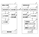
図1は、画像出力システムの参考構成例1を示すブロック図である。この画像出力システムは、いわゆるダイレクト印刷システムの一種である。図1において、画像出力装置1は、画像データに基づき画像を出力する装置である。画像出力装置1の形態としては、画像データに基づき画像を紙などに印刷するプリンタなどがある。また、画像供給装置2は、画像データを格納し、必要に応じてその画像データを送信可能な装置である。画像供給装置2の形態としては、撮影した画像を画像データとして所定の記録媒体に記憶するデジタルカメラなどがある。
【0087】
通信路3は、画像出力装置1と画像供給装置2とを接続する伝送媒体である。この通信路3は、有線の通信路に限定されず、無線の通信路を使用してもよい。この参考構成例1では、通信路3には、USB(Universal Serial Bus)のケーブルが使用される。なお、通信路3が有線通信路である場合には、画像出力装置1と画像供給装置2には図示せぬコネクタが設けられ、通信路3のケーブルの両端のコネクタと両装置1,2のコネクタとが、それぞれ接続される。
【0088】
図1に示す画像出力装置1において、通信回路11は、通信路3を介して各種情報を電気信号として送受する回路である。また、通信制御部12は、通信回路11を制御し、各種プロトコルに従って通信相手と情報を送受する回路または装置である。なお、この通信回路11および通信制御部12は、画像出力(印刷)に係る制御情報をマークアップ言語で記述した一連のスクリプトとして通信路3を介して送受する第1の通信手段として機能する。
【0089】
また、出力制御部13は、出力機構14を制御および監視し、画像出力処理(画像出力装置1がプリンタなどの印刷装置である場合には印刷処理)を制御する回路または装置である。この参考構成例1では、この出力制御部13が、画像出力の処理フローを制御する画像出力制御手段として機能する。出力機構14は、画像を出力する機械的および/または電気的な構成部である。
【0090】
例えば、プリンタなどの場合の出力機構14、すなわち印刷手段としては、印字機構、紙送り機構などが該当する。また、出力制御部13は、印刷手段としての出力機構14を制御する印刷制御手段として機能する。
【0091】
また、操作部15は、ユーザにより操作され、その操作に応じた信号を出力する回路または装置である。この操作部15としては、各種スイッチ、タッチパネルなどが、適宜使用される。表示装置16は、各種情報を表示する装置である。この表示装置16としては、各種インジケータ、液晶ディスプレイなどが、適宜使用される。
【0092】
電源回路17は、例えば商用電源やAC/DC変換器に接続され、供給された電力を所定の電圧で内部の回路に供給する回路である。
【0093】
図1に示す画像供給装置2において、通信回路21は、通信路3を介して各種情報を電気信号として送受する回路である。また、通信制御部22は、通信回路21を制御し、各種プロトコルに従って通信相手と情報を送受する回路または装置である。なお、この通信回路21および通信制御部22は、画像出力に係る制御情報をマークアップ言語で記述した一連のスクリプトとして通信路3を介して送受する第2の通信手段として機能する。
【0094】
また、中央制御部23は、通信制御部22、記録媒体24などの各種機能の有する回路または装置との間で各種情報の授受を行いながら、各種処理を実行する回路または装置である。
【0095】
記録媒体24は、画像データを含む1または複数の画像データファイル31を格納する装置である。画像データファイル31は、例えばデジタルカメラにより撮影された画像、その他の画像の画像データを含むファイルである。この画像データの形式は、例えばJPEG(Joint Photographic Experts Group)形式、EXIF(EXchangeable Image File )形式などとされる。
【0096】
なお、記録媒体24としては、半導体メモリ、半導体メモリを使用したメモリカード、磁気記録媒体、光記録媒体、光磁気記録媒体などが使用され、画像供給装置2の内部に固定されていてもよいし、画像供給装置2に対して着脱可能でもよい。
【0097】
操作部25は、ユーザにより操作され、その操作に応じた信号を出力する回路または装置である。この操作部15としては、各種スイッチ、タッチパネルなどが、適宜使用される。表示装置26は、画像データに基づく画像などの各種情報を表示する装置である。この表示装置26としては、各種インジケータ、液晶ディスプレイなどが、適宜使用される。
【0098】
バッテリ27は、画像供給装置2の内部回路に電力を供給する電池である。なお、バッテリ27としては、蓄電池、使い捨て電池などが使用される。また、画像供給装置2が可搬性を要求される装置である場合には、電源としてバッテリ27が設けられるが、画像供給装置2が可搬性を要求されない装置である場合には、電源として画像出力装置1の電源回路17のような電源回路を代わりに設けるようにしてもよい。
【0099】
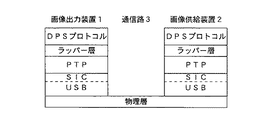
図2は、画像出力システムの参考構成例1において、画像出力装置1と画像供給装置2との間で使用されるプロトコルの一例を示す図である。
【0100】
この参考構成例1では、まず、物理層として、上述のとおり、USBケーブルである通信路3が使用される。そして、この参考構成例1における画像出力装置1および画像供給装置2では、その物理層を制御する層として、USB層があり、USBクラスとしてスチルイメージクラス(SIC)が使用される。これにより、データ伝送路が実現される。なお、USB規格については、現在USB1.1、USB2.0など存在するが、将来提案される次バージョン以降のものでもよく、USBと同等の通信規格のものを代わりに使用してもよい。なお、通信路3にUSBを使用する場合、画像出力装置1がホストとなり、画像供給装置2がデバイスとなる。
【0101】
そして、その上位において、デジタル静止画装置(DSPD)の外部からの制御やデジタル静止画装置(DSPD)の外部への画像データ転送を規定した画像転送プロトコル(PTP)が使用される。なお、PTPの標準規格としては、PHOTOGRAPHIC AND IMAGING MANUFACTURERS ASSOCIATION,INCの「PIMA15740:2000」がある。なお、PTPは、DSPD間での画像データの交換のための通信方式を提供するプロトコルであり、PTPでは、ストレージ内のオブジェクト(画像データファイルなど)は、パスではなく、オブジェクトID(オブジェクトハンドル)で指定される。
【0102】
この参考構成例1では、上述のPTPの上位で、デジタルカメラなどの画像供給装置2に格納された画像データを、通信路3を介して直接、プリンタなどの画像出力装置1へ供給し、印刷を行うためのプロトコルであるダイレクト印刷サービス(以下、DPSという)プロトコルが使用される。DPSプロトコルでは、画像出力装置1と画像供給装置2との間で、画像出力に係る制御情報が、マークアップ言語(ここでは、XML;eXtensible Markup Language)で記述した一連のスクリプトとして通信路3を介して送受される。なお、画像出力に係る制御情報としては、画像出力処理における各種コマンド、そのコマンドに対する応答、装置の状態の通知などがある。また、このスクリプトには、制御情報のみが含まれ、画像出力の対象となる画像データ自体は含まれない。すなわち、画像データファイルの格納場所などの情報はこのスクリプトに含まれるが、画像データそのものは含まれない。
【0103】
なお、DPSプロトコルの下位層はPTPに限定されない。そのため、DPSプロトコルと複数種類の下位層との整合性を得るために、DPSプロトコルと下位層(ここではPTP)との間にはラッパー層が設けられている。
【0104】
この参考構成例1では、上述の各プロトコルのうち、物理層が、通信回路11、通信路3および通信回路21により実現され、USB層が、通信回路11および通信回路21により実現され、PTP層、ラッパー層およびDPSプロトコル層が、通信制御部12および通信制御部22により実現される。
【0105】
すなわち、通信制御部12,22が、それぞれ、マークアップ言語で記述した画像出力に係る制御情報を送受する画像出力制御プロトコルであるDPSプロトコルを解釈する第1のエンティティ、第1のエンティティに下位層で、画像供給装置2に格納された画像データを管理し画像出力装置1へ転送する画像データ管理転送プロトコルであるPTPを解釈する第2のエンティティ、および第2のエンティティに下位層で、通信路3の物理層を制御する第3のエンティティとして機能する。
【0106】
また、各通信制御部12,22のラッパー層の部分が、第2のエンティティの画像データ管理転送プロトコルの種類に応じた、第1のエンティティの画像出力制御プロトコルと画像データ管理転送プロトコルとの間でのプロトコル変換を行うプロトコル変換手段として機能する。すなわち、必要に応じて、各通信制御部12,22のラッパー層が、上位プロトコル(DPSプロトコル)のコマンドを下位プロトコル(PTP)のコマンドに置き換える。
【0107】
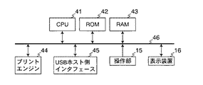
図3は、画像出力システムの参考構成例1における画像出力装置としてのプリンタの構成例を示すブロック図である。図3において、CPU41は、プログラムを実行し、プログラムに記述された処理を実行する装置である。また、ROM42は、プログラムおよびデータを予め記憶したメモリである。また、RAM43は、プログラムを実行する際にそのプログラムおよびデータを一時的に記憶するメモリである。
【0108】
なお、CPU41が実行するプログラムとしては、画像データから印刷制御データを生成するためのプログラム、その印刷制御データに基づいて出力機構14などを制御する制御プログラム、並びにDPSプロトコルおよび画像転送プロトコルに従って通信を行うための制御プログラムがROM42または図示せぬ他の記録媒体に格納されている。
【0109】
プリントエンジン44は、CPU41から供給される印刷制御データに基づいて出力機構14を制御して印刷処理を実行する回路または装置である。
【0110】
USBホスト側インタフェース45は、図1の通信回路11に該当し、USBに規定されたホスト側のインタフェース回路である。
【0111】
バス46は、CPU41、ROM42、RAM43、プリントエンジン44、USBホスト側インタフェース45、操作部15および表示装置16を相互に接続する信号路である。なお、バス46の本数、およびCPU41、プリントエンジン44などのバス46への接続のトポロジは、図3のものに限定されるものではない。
【0112】
なお、図3における操作部15および表示装置16は、図1のものと同様である。
【0113】
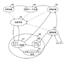
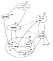
図4は、画像出力システムの参考構成例1における画像出力装置1の有する複数の機能の関係を示す図である。図4において、通信制御機能51は、画像転送プロトコル以下の通信制御を行う機能である。
【0114】
また、DPSプロトコル処理機能52は、DPSプロトコルに規定された制御情報を生成または解釈するDPSコマンド処理機能61、制御情報に対応するXMLスクリプトを生成するXMLスクリプト生成機能62、およびXMLで記述された制御情報を構文解析するXMLパーサ63を含む。
【0115】
なお、このXMLパーサ63は、XMLのすべての構文を解析可能に設計されていてもよいし、DPSプロトコルで使用される構文のみを解析可能としてもよい。その場合には、XMLパーサ63は、DPSプロトコルに係るXMLスクリプトの記述に必要なタグのみを判別できればよい。
【0116】
また、このXMLスクリプト生成機能62は、XMLスクリプトのテンプレートをコマンドなどの制御情報の種類ごとにROM42などに予め格納し、そのテンプレートを編集して、制御情報を示すXMLスクリプトを生成するようにしてもよい。
【0117】
また、画像処理機能53は、画像データのフォーマットを変更する機能であり、印刷データ生成機能54は、フォーマット変更後の画像データから印刷制御データを生成する機能であり、印刷制御機能55は、印刷制御データに従って印刷処理を実行させる機能である。
【0118】
また、状態管理機能56は、上述の各機能による処理の状態を監視する機能である。
【0119】
なお、これらの機能は、上述のプログラムをCPU41により実行することで実現される。また、通信制御機能51およびDPSプロトコル処理機能52により通信制御部12が実現され、画像処理機能53、印刷データ生成機能54、印刷制御機能55および状態管理機能56により出力制御部13が実現される。
【0120】
図5は、画像出力システムの参考構成例1における画像供給装置2としてのデジタルカメラの構成例を示すブロック図である。図5において、CPU71は、プログラムを実行し、プログラムに記述された処理を実行する装置である。また、ROM72は、プログラムおよびデータを予め記憶したメモリである。また、RAM73は、プログラムを実行する際にそのプログラムおよびデータを一時的に記憶するメモリである。
【0121】
なお、CPU71が実行するプログラムとしては、撮影時の各部の制御を行うためのプログラム、並びにDPSプロトコルおよび画像転送プロトコルに従って通信および画像データの管理を行うための制御プログラムがROM72または図示せぬ他の記録媒体に格納されている。
【0122】
撮影装置74は、CPU71からの指令に応じて、被写体の撮影を行い、撮影後の画像データを、メモリカード75に格納する装置である。
【0123】
メモリカード75は、図1の記録媒体24に該当し、撮影により得られた画像データなどを格納する記録媒体である。なお、メモリカード75の代わりに、装置内に固定された半導体メモリ、磁気記録装置などを使用するようにしてもよい。
【0124】
USBデバイス側インタフェース76は、図1の通信回路21に該当し、USBに規定されたデバイス側のインタフェース回路である。
【0125】
バス77は、CPU71、ROM72、RAM73、撮影装置74、メモリカード75、USBデバイス側インタフェース76、操作部25、および表示装置26を相互に接続する信号路である。なお、バス77の本数、およびCPU71などのバス77への接続のトポロジは、図5のものに限定されるものではない。
【0126】
なお、図5における操作部25および表示装置26は、図1のものと同様である。
【0127】
図6は、画像出力システムの参考構成例1における画像供給装置2の有する複数の機能の関係を示す図である。図6において、通信制御機能81は、画像転送プロトコル以下の通信制御を行う機能である。また、DPSプロトコル処理機能82は、DPSプロトコルに規定された制御情報を生成または解釈するDPSコマンド処理機能91、制御情報に対応するXMLスクリプトを生成するXMLスクリプト生成機能92、およびXMLで記述された制御情報を構文解析するXMLパーサ93を含む。
【0128】
なお、このXMLパーサ93は、XMLのすべての構文を解析可能に設計されていてもよいし、DPSプロトコルで使用される構文のみを解析可能としてもよい。その場合には、XMLパーサ93は、DPSプロトコルに係るXMLスクリプトの記述に必要なタグのみを判別できればよい。
【0129】
また、このXMLスクリプト生成機能92は、XMLスクリプトのテンプレートをコマンドなどの制御情報の種類ごとにROM72などに予め格納し、そのテンプレートを編集して、制御情報を示すXMLスクリプトを生成するようにしてもよい。
【0130】
また、ファイルシステム管理機能83は、記録媒体24としてのメモリカード75に、所定のディレクトリ構造およびファイル構造に従って、画像データを画像データファイル31として保持する機能である。
【0131】
また、ユーザインタフェース機能84は、ユーザによる操作部25への操作の受け付け、および表示装置26での各種情報の表示を行う機能である。
【0132】
また、設定管理機能85は、ユーザによる操作に応じて、印刷処理などの条件を設定する機能である。状態管理機能86は、上述の各機能による処理の状態を監視する機能である。
【0133】
なお、これらの機能は、上述のプログラムをCPU71により実行することで実現される。また、ファイルシステム管理機能83、ユーザインタフェース機能84、設定管理機能85および状態管理機能86により中央制御部23が実現され、通信制御機能81およびDPSプロトコル処理機能82により通信制御部22が実現される。
【0134】
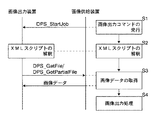
次に、上記システムにおける各装置の動作について説明する。図7は、画像出力システムの参考構成例1における、DPSプロトコルレベルでの画像出力処理を説明する図である。図8は、画像出力システムの参考構成例1における、画像転送プロトコルレベルでの画像出力処理を説明する図である。
【0135】
まず、例えば操作部25に対して所定の操作があると、画像供給装置2が、通信路3を介して画像出力装置1へ、印刷ジョブ開始コマンドを送信する(ステップS1)。
【0136】
その際、画像供給装置2では、通信制御部22が、DPSプロトコルに従って、印刷ジョブ開始コマンドDPS_StartJobのXMLスクリプトを生成し、送信する。ここでは、このXMLスクリプト内で、画像出力の対象となる画像データが指定される。
【0137】
なお、印刷ジョブ開始コマンドDPS_StartJobには、次のジョブ条件設定情報および画像出力情報が含まれる。
【0138】
ジョブ条件設定情報としては、このジョブでの画像出力の品質を設定するクオリティ情報、印刷ジョブにおける用紙タイプ情報、印刷ジョブにおける用紙サイズ情報、画像形式情報、画像最適化設定情報、ページレイアウト情報などが必要に応じて含まれる。
【0139】
画像出力情報としては、クロッピングを行う際の領域を指定するクロッピングエリア情報、画像データのオブジェクトID、各画像についての印刷部数情報、各ジョブを固有なジョブID、画像データまたはジョブ指定ファイルのパス情報、各画像データの繰り返し供給回数情報(すなわち、同一の画像データを連続して何回、画像出力装置1へ供給するかを示す情報)などが必要に応じて含まれる。また、画像出力情報には、複数の画像の指定を含めることができ、複数のジョブの指定を含めることができる。
【0140】
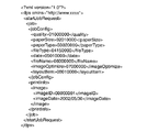
図9は、画像出力システムの参考構成例1において使用される印刷ジョブ開始コマンドDPS_StartJobのXMLスクリプトの一例を示す図である。図9において、jobタグは、1つのジョブを指定するためのタグである。なお、xxタグといった場合、<xx>タグと</xx>タグの両方を指すものとする(以下、同様)。jobタグの下位には、jobConfigタグおよびPrintInfoタグが配置される。jobConfigタグは、ジョブ条件設定情報を指定するためのタグである。
【0141】
図9に示すスクリプトにおいては、jobConfigタグの下位に、qualityタグ、paperSizeタグ、paperTypeタグ、fileTypeタグ、dateタグ、fileNameタグ、imageOptimizeタグ、およびlayoutItemタグが配置される。
【0142】
qualityタグは、標準、ドラフト、ファインなどのクオリティ情報を指定するためのタグである。paperSizeタグは、A4サイズなどの、このジョブにおける用紙サイズ情報を指定するためのタグであり、所定の数値(例えば、02010000)で、用紙サイズが指定される。paperTypeタグは、標準用紙、写真用紙などの、このジョブにおける用紙タイプ情報を指定するためのタグであり、所定の数値(例えば、03020000)で、用紙サイズが指定される。fileTypeタグは、EXIF、JPEG、TIFF、GIFなどの、このジョブにおける画像形式情報を指定するためのタグであり、所定の数値(例えば、03020000)で、画像形式が指定される。
【0143】
さらに、dateタグは、printInfoで指定される日付情報を印刷するか否かを指定するためのタグである。fileNameタグは、printInfoで指定されるファイルパス情報を印刷するか否かを指定するためのタグである。imageOptimizeタグは、画像最適化を行うか否かを示す画像最適化設定情報を指定するためのタグである。layoutItemタグは、このジョブにおけるページレイアウトを指定するためのタグであり、所定の数値(例えば、08010000)で、画像形式が指定される。
【0144】
また、printInfoタグは、画像出力情報を指定するためのタグである。printInfoタグの下位には、imageタグが配置される。imageタグは、画像出力対象の画像を指定するためのタグである。図9に示すスクリプトにおいては、imageタグの下位に、imageIDタグおよびimageDateタグが配置される。imageIDタグは、画像出力対象の画像データのオブジェクトIDを指定するためのタグである。imageDateタグは、画像の脇に印刷される日付を指定するためのタグである。
【0145】
図9に示すスクリプトでは、imageタグは、1つだけであるが、複数の画像を出力する場合には、複数の画像のうちの各画像について、imageタグにより画像データのオブジェクトIDが指定される。また、同一の画像を複数回連続して出力する場合には、その画像のimageタグの次に、copiesタグを配置して、その繰り返し供給回数を指定すればよい。
【0146】
なお、図9におけるdpsタグは、DPSに係るXMLスクリプトであることを示すタグであり、属性としてDPSで使用される名前空間情報の格納場所のURL(Uniform Resource Locator)をとる。
【0147】
画像供給装置2の通信制御部22は、DPSプロトコル上ではジョブ開始コマンドのXMLスクリプトを論理的には送信するが、そのXMLスクリプトを画像転送プロトコルのコマンドに変換し、画像転送プロトコルのレベルでそのコマンドを処理する。
【0148】
つまり、画像転送プロトコルに従って、画像供給装置2の通信制御部22は、まず、ファイル転送要求コマンドRequestObjectTransferを送信する(ステップSS1)。このコマンドは、USB層および物理層を介して画像出力装置1に伝送される。
【0149】
画像出力装置1では、通信制御部12が、画像転送プロトコルに従って、ファイル転送要求コマンドRequestObjectTransferを受信すると、転送するファイルの属性を問い合わせるコマンドGetObjectInfoを送信する(ステップSS2)。このコマンドは、USB層および物理層を介して画像供給装置2に伝送される。
【0150】
画像供給装置2では、通信制御部22が、画像転送プロトコルに従って、コマンドGetObjectInfoを受信すると、コマンドDPS_StartJobのXMLスクリプトのファイル情報(ファイル形式、ファイル容量など)を送信する(ステップSS3)。このファイル情報は、USB層および物理層を介して画像出力装置1に伝送される。
【0151】
画像出力装置1では、通信制御部12が、画像転送プロトコルに従って、そのファイル情報を受信すると、そのXMLスクリプトを指定してファイル取得コマンドGetObjectを送信する(ステップSS4)。このファイル情報は、USB層および物理層を介して画像供給装置2に伝送される。
【0152】
画像供給装置2では、通信制御部22が、画像転送プロトコルに従って、コマンドGetObjectを受信すると、指定されたファイル(コマンドDPS_StartJobのXMLスクリプト)を送信する(ステップSS5)。このファイルは、USB層および物理層を介して画像出力装置1に伝送される。
【0153】
画像出力装置1では、通信制御部12が、画像転送プロトコルに従ってそのファイルを受信すると、DPSプロトコル層においてコマンドDPS_StartJobを受信したこととなる。
【0154】
ここで、画像出力装置1が図3および図4に示すプリンタであり、かつ画像供給装置2が図5および図6に示すデジタルカメラである場合、DPSプロトコルでの通信は、DPSプロトコル処理機能52,82および通信制御機能51,81により行われ、画像転送プロトコルでの通信は、通信制御機能51と通信制御機能81との間で行われる。
【0155】
次に、画像出力装置1は、取得した印刷ジョブ開始コマンドのXMLスクリプトを解釈し(ステップS2)、そのXMLスクリプトに記述された画像出力の対象である画像データを画像供給装置2から取得する(ステップS3)。
【0156】
この参考構成例1では、画像供給装置2からの印刷ジョブ開始コマンドを受けた後、画像出力装置1が、その印刷ジョブの処理フローを制御する。すなわち、画像出力装置1が、画像出力処理の進行を管理し、画像出力処理に必要な情報や画像データを画像供給装置2から適宜取得する。
【0157】
その際、画像出力装置1では、通信制御部12が、DPSプロトコルに従って、XMLスクリプト内に記載されたオブジェクトID(PTPにおけるオブジェクトIDに対応)で画像データファイル31を指定してXMLスクリプトのファイル取得コマンドDPS_GetFileを発行する。なお、あるオブジェクトについてのPTPにおけるオブジェクトIDとDPSプロトコルにおけるオブジェクトIDは、同値としてもよいし、互いに異なる値としてもよい。両者の値が異なる場合には、DPSプロトコルとPTPとの間で、オブジェクトIDのマッピングが適宜行われる。
【0158】
図10は、画像出力システムの参考構成例1において使用されるファイル取得コマンドDPS_GetFileのXMLスクリプトの一例を示す図である。図10において、getFileRequestタグは、ファイル取得コマンドであることを示すタグである。図10においては、getFileRequestタグの下位に、fileIDタグおよびbuffPtrタグが配置される。fileIDタグは、取得対象のファイルのオブジェクトIDを指定するためのタグである。buffPtrタグは、取得したファイルの受信に使用するバッファへのポインタを指定するためのタグである。
【0159】
通信制御部12は、そのDPSプロトコルのファイル取得コマンドDPS_GetFileを、画像転送プロトコルのファイル取得コマンドGetObjectに変換し、送信する。このコマンドは、USB層および物理層を介して画像供給装置2に伝送される。
【0160】
なお、ファイル全体を取得するファイル取得コマンドDPS_GetFileの代わりに、ファイルの一部を取得するファイル部分取得コマンドDPS_GetPartialFileを複数回送信してファイル全体を取得するようにしてもよい。このファイル部分取得コマンドDPS_GetPartialFileは、画像転送プロトコルのコマンドGetPartialObjectに変換される。
【0161】
画像供給装置2では、通信制御部22が、画像転送プロトコルに従って、コマンドGetObjectを受信すると、指定されたオブジェクトIDのファイル(画像データファイル31)を読み出し、送信する。このファイルは、USB層および物理層を介して画像出力装置1に伝送される。
【0162】
画像出力装置1では、通信制御部12が、画像転送プロトコルに従ってそのファイルを受信すると、DPSプロトコル層においてもそのファイルを受信したこととなる。
【0163】
ここで、画像出力装置1が図3および図4に示すプリンタであり、かつ画像供給装置2が図5および図6に示すデジタルカメラである場合、この画像データの取得には、画像出力装置1におけるDPSプロトコル処理機能52および通信制御機能51、並びに、画像供給装置2における通信制御機能81およびファイルシステム管理機能83が使用される。
【0164】
そして、画像出力装置1は、画像データを取得すると、その画像データに基づく画像を出力する(ステップS4)。その際、画像出力装置1では、出力制御部13および出力機構14が、画像出力処理を行う。
【0165】
ここで、画像出力装置1が図3および図4に示すプリンタである場合、画像出力処理には、画像処理機能53、印刷データ生成機能54および印刷制御機能55が使用される。
【0166】
以上のように、上記画像出力システムの参考構成例1によれば、画像出力装置1および画像供給装置2が、画像出力に係る制御情報をマークアップ言語で記述した一連のスクリプトとして通信路3を介して送受する。これにより、マークアップ言語の構文の拡張性を利用して複数ベンダに対する互換性を維持しつつ、規定後にプロトコルを修正し易くすることができる。
【0167】
さらに、上記画像出力システムの参考構成例1によれば、マークアップ言語として、文書型を追加定義可能であるXMLを使用する。これにより、規定後にプロトコルをより修正し易くすることができる。
【0168】
さらに、上記画像出力システムの参考構成例1によれば、通信制御部12,22が、マークアップ言語で記述した画像出力に係る制御情報を送受するDPSプロトコルを解釈する第1のエンティティと、第1のエンティティに下位層で、画像供給装置2に格納された画像データを管理し画像出力装置1へ転送するPTPを解釈する第2のエンティティと、第2のエンティティに下位層で、通信路3の物理層(ここではUSB)を制御する第3のエンティティとしてそれぞれ機能する。これにより、PTP以下の階層では様々な既存のプロトコルを使用でき、規定後に画像出力に係るプロトコルを修正したい場合に、DPSプロトコルのみを修正すればよく、修正規模を小さくすることができる。
【0169】
さらに、上記画像出力システムの参考構成例1によれば、通信制御部12,22は、ラッパー層にて、第2のエンティティの画像データ管理転送プロトコルの種類(ここではPTP)に応じた、第1のエンティティのDPSプロトコルと画像データ管理転送プロトコルとの間でのプロトコル変換を行う。これにより、採用される画像データ管理転送プロトコルの違いがラッパー層で吸収されるため、規定後に画像出力に係るプロトコルを修正したい場合に、ラッパー層をほとんど修正せずに画像出力制御プロトコルのみを修正すればよく、修正規模を小さくすることができる。
【0170】
さらに、上記画像出力システムの参考構成例1によれば、画像出力装置1の出力制御部13が、画像出力の処理フローを制御する。これにより、画像供給装置2の情報処理量がほとんど増加せず、画像供給装置2の情報処理性能が低くても本システムを実現することができる。
【0171】
さらに、上記画像出力システムの参考構成例1によれば、通信制御部12,22が、画像出力に係る制御情報として、画像出力処理における制御コマンド、その制御コマンドに対する応答、および装置の状態(ジョブの状態を含む)の通知をマークアップ言語で記述した一連のスクリプトとして送受する。これにより、テキストベースで読み易い制御コマンド、その応答、装置の状態通知などを送受でき、複数ベンダに対する互換性を維持しつつ、規定後にプロトコルを修正し易くすることができる。
【0172】
さらに、上記画像出力システムの参考構成例1によれば、通信制御部12,22が、マークアップ言語で記述した一連のスクリプトとして、画像出力の対象となる画像データを含まず、画像出力に係る制御情報のみを含むスクリプトを送受する。これにより、画像出力の対象となるデータの形式を既存のものから変更することなく、画像出力の対象となるデータから独立してマークアップ言語による制御情報を送受することができる。
【0173】
さらに、上記画像出力システムの参考構成例1によれば、画像出力装置1が、画像を出力する出力機構14と、画像データから出力機構を制御するための印刷制御データを生成しその印刷制御データに基づいて出力機構を制御する出力制御部13とを備える。これにより、画像供給装置2には、画像データから出力機構を制御する印刷制御データを生成する機能(パーソナルコンピュータなどで使用される従来のプリンタドライバに含まれる機能)がなくてもよく、画像供給装置2を安価にすることができる。
【0174】
さらに、上記画像出力システムの参考構成例1によれば、画像出力装置1のXMLパーサ63を、マークアップ言語のタグのうち、画像出力に係る制御情報の記述に必要なタグのみを判別するようにした場合には、XMLパーサ63を小規模な回路やプログラムで実現でき、画像出力装置1を安価にすることができる。
【0175】
さらに、上記画像出力システムの参考構成例1によれば、画像供給装置2のXMLパーサ93を、マークアップ言語のタグのうち、画像出力に係る制御情報の記述に必要なタグのみを判別するようにした場合には、XMLパーサ93を小規模な回路やプログラムで実現でき、画像供給装置2を安価にすることができる。
【0176】
さらに、上記画像出力システムの参考構成例1によれば、通信制御部12,22が、スクリプトのテンプレートを制御情報の種類ごとに格納し、そのテンプレートから制御情報のスクリプトを生成する。これにより、テンプレートで確定していない部分のみを編集すればよいため、短時間で制御情報のスクリプトを生成することができる。
【0177】
さらに、上記画像出力システムの参考構成例1によれば、画像供給装置2の通信制御部22および通信回路21は、操作部25に対して所定の操作があると、印刷ジョブ開始コマンドを制御情報として画像出力装置1に送信する。画像出力装置1の出力制御部13は、通信制御部12および通信回路11により印刷ジョブ開始コマンドが受信されると、その印刷ジョブ開始コマンドに従って画像出力の処理を開始する。これにより、ユーザが画像供給装置2の操作部25を操作することで画像出力を行わせることができるため、画像供給装置2がユーザフレンドリな操作部25を有している場合にその操作部25により操作性が向上する。
【0178】
さらに、上記画像出力システムの参考構成例1によれば、画像出力装置1の通信制御部12は、画像出力の処理において、画像供給装置2に格納された画像データが必要になると、その画像データの転送要求を画像供給装置2に送信する。画像供給装置2の通信制御部22は、その画像データの転送要求を受信すると、その画像データを画像出力装置1に送信する。これにより、画像供給装置2は画像出力装置1からの要求に応じて画像データを送信すればよいため、画像供給装置2の情報処理量がほとんど増加せず、画像供給装置2の情報処理性能が低くても本システムを実現することができる。
【0179】
画像出力システムの参考構成例2.
画像出力システムの参考構成例2では、画像供給装置2が、画像データおよび印刷ジョブを指定するジョブ指定ファイルを格納し、画像出力装置1が、そのジョブ指定ファイルを取得し、そのジョブ指定ファイルの情報に基づいて、マークアップ言語で記述した画像出力に係る制御情報を生成する。
【0180】
この参考構成例2では、画像データおよびジョブ指定ファイルが、DPOF(Digital Print Order Format)方式で記録媒体24に格納される。DPOF規格は、現在DPOF1.10のバージョンであるが、将来提案される次バージョン以降のものであってもよい。また、同等の作用を得られる他の規格のものをDPOFの代わりに使用してもよい。
【0181】
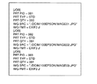
図11は、DPOF方式のディレクトリ構造を説明する図である。DPOF方式のディレクトリ構造では、ルートの下位ディレクトリとして、画像データファイルの上位となるディレクトリDCIMおよびジョブ指定ファイルの上位となるディレクトリMISCがある。ディレクトリDCIMの下位には、ベンダ固有のディレクトリ(ここでは、100EPSON)が設けられ、その中に画像データファイル(ここでは、IMAGE01.JPGなど)がある。一方、ディレクトリMISCには、印刷ジョブの指定ファイルであるAUTPRINT.MRKがある。DPOF方式のジョブ指定ファイルAUTPRINT.MRKには、プリントジョブ情報、画像ソース情報、印刷設定情報などが含まれている。
【0182】
図12は、DPOF方式のジョブ指定ファイルAUTPRINT.MRKの一例を示す図である。図12に示す自動印刷ファイルAUTPRINT.MRKには、3つのジョブが含まれており、それぞれのジョブに対して、ジョブID(PRT PID)、印刷種類(PRT TYP)、印刷部数(PRT QTY)、画像データの格納場所(IMG SRC)、および画像データのフォーマット(IMG FMT)が指定されている。
【0183】
なお、この参考構成例2における画像出力装置1および画像供給装置2の基本的な構成は、上記参考構成例1の場合と同様である。ただし、この参考構成例2における通信制御部12および通信制御部22の動作は、以下に説明するように変更される。
【0184】
次に、上記システムの各装置の動作について説明する。図13は、画像出力システムの参考構成例2における、DPSプロトコルレベルでの画像出力処理を説明する図である。図14は、画像出力システムの参考構成例2における、画像転送プロトコルレベルでの画像出力処理を説明する図である。
【0185】
まず、例えば操作部25に対して所定の操作があると、画像供給装置2が、通信路3を介して画像出力装置1へ、印刷ジョブ開始コマンドを送信する(ステップS21)。
【0186】
その際、画像供給装置2では、通信制御部22が、印刷ジョブ開始コマンドDPS_StartJobのXMLスクリプトを生成し、送信する。ここでは、このXMLスクリプト内で、ジョブ指定ファイルを使用することが記述される。すなわち、例えば図9に示すようなスクリプトにおいて、画像データを指定するimageIDタグでジョブ指定ファイルが指定される。その指定には、ジョブ指定ファイルのオブジェクトIDが使用される。
【0187】
この印刷ジョブ開始コマンドDPS_StartJobのXMLスクリプトのついての画像供給装置2から画像出力装置1への伝送の際の通信処理は、上記参考構成例1におけるステップS1の場合と同様であるので、その説明を省略する。
【0188】
次に、画像出力装置1は、取得したXMLスクリプトを解釈し(ステップS22)、そのXMLスクリプトに記述されたジョブ指定ファイルを画像供給装置2から取得する(ステップS23)。
【0189】
その際、画像出力装置1では、通信制御部12が、DPSプロトコルに従って、XMLスクリプト内に記載されたオブジェクトID(PTPにおけるオブジェクトIDに対応)でジョブ指定ファイルを指定してXMLスクリプトのファイル情報取得コマンドDPS_GetFileInfoを送信する。通信制御部12は、そのDPSプロトコルのファイル情報取得コマンドDPS_GetFileInfoを、画像転送プロトコルのファイル情報取得コマンドGetObjectInfoに変換し、送信する(ステップSS11)。このコマンドは、USB層および物理層を介して画像供給装置2に伝送される。
【0190】
画像供給装置2では、通信制御部22が、画像転送プロトコルに従って、コマンドGetObjectInfoを受信すると、指定されたオブジェクトIDのファイルのファイル情報を送信する(ステップSS12)。このファイル情報は、USB層および物理層を介して画像出力装置1に伝送される。
【0191】
画像出力装置1では、通信制御部12が、画像転送プロトコルに従ってそのファイル情報を受信すると、そのファイル情報をXMLスクリプトとして記述し、DPSプロトコル層に渡す。
【0192】
次に、画像出力装置1では、通信制御部12が、DPSプロトコルに従って、オブジェクトIDでジョブ指定ファイルを指定してXMLスクリプトのファイル取得コマンドDPS_GetFileを発行する。通信制御部12は、そのDPSプロトコルのファイル取得コマンドDPS_GetFileを、画像転送プロトコルのファイル取得コマンドGetObjectに変換し、送信する(ステップSS13)。このコマンドは、USB層および物理層を介して画像供給装置2に伝送される。
【0193】
画像供給装置2では、通信制御部22が、画像転送プロトコルに従って、コマンドGetObjectを受信すると、指定されたオブジェクトIDのファイル(ジョブ指定ファイル)を読み出し、送信する(ステップSS14)。このファイルは、USB層および物理層を介して画像出力装置1に伝送される。
【0194】
画像出力装置1では、通信制御部12が、画像転送プロトコルに従ってそのファイルを受信すると、DPSプロトコル層においてもそのファイルを受信したこととなる。
【0195】
ここで、画像出力装置1が図3および図4に示すプリンタであり、かつ画像供給装置2が図5および図6に示すデジタルカメラである場合、このジョブ指定ファイルの取得には、画像出力装置1におけるDPSプロトコル処理機能52および通信制御機能51、並びに、画像供給装置2における通信制御機能81およびファイルシステム管理機能83が使用される。
【0196】
そして、画像出力装置1の通信制御部12は、ジョブ指定ファイルを取得すると、そのジョブ指定ファイルを解釈する(ステップS24)。
【0197】
画像出力装置1の通信制御部12は、そのジョブ指定ファイルに記述された各ジョブにおいて指定された画像データを画像供給装置2から取得する(ステップS25)。
【0198】
その際、まず、DPOF方式のジョブ指定ファイルAUTPRINT.MRKでは、画像データファイルの格納場所が相対パスで記述されているため、その画像データのオブジェクトIDを取得するために、画像出力装置1では、通信制御部12が、DPSプロトコルに従って、パスを指定してそのパスのファイルのオブジェクトIDを取得するためのコマンドDPS_GetObjectIDをXMLスクリプトとして生成し、送信する。
【0199】
図15は、画像出力システムの参考構成例2において使用されるオブジェクトID取得コマンドDPS_GetObjectIDのXMLスクリプトの一例を示す図である。図15において、getObjectIDRequestタグは、オブジェクトID取得コマンドであることを示すタグである。図15においては、getObjectIDRequestタグの下位に、basePathIDタグおよびimagePathタグが配置される。basePathIDタグは、imagePathタグで指定する相対パスの基礎となるディレクトリを指定するためのタグである。imagePathタグは、オブジェクトIDを取得する対象となるファイルを、basePathIDタグで指定されたディレクトリからの相対パスで指定するためのタグである。
【0200】
画像出力装置1の通信制御部12は、DPSプロトコル層でのコマンドDPS_GetObjectIDの発行を受けて、画像転送プロトコルに従って、コマンドSendObjectInfoとXMLスクリプトのファイル情報、およびコマンドSendObjectとXMLスクリプトを送信する(ステップSS21〜SS24)。これらのコマンド、ファイル情報およびXMLスクリプトは、USB層および物理層を介して画像供給装置2に伝送される。
【0201】
画像供給装置2では、通信制御部22は、画像転送プロトコルに従って、それらのコマンド、ファイル情報およびXMLスクリプトを受信し、DPSプロトコルに従って、XMLスクリプトであるコマンドDPS_GetObjectIDを受信する。
【0202】
画像供給装置2の通信制御部22は、DPSプロトコルに従って、受信したコマンドDPS_GetObjectIDのXMLスクリプトを解釈し、コマンドDPS_GetObjectIDで指定されたパスのファイルに割り当てられているオブジェクトIDを特定し、コマンドDPS_GetObjectIDに対する応答として、そのオブジェクトIDを示すXMLスクリプトを生成し、送信する。
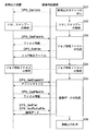
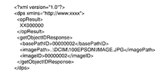
【0203】
図16は、画像出力システムの参考構成例2において使用されるオブジェクトID取得コマンドDPS_GetObjectIDの応答のXMLスクリプトの一例を示す図である。図16において、opResultタグは、オブジェクトID取得コマンドの処理結果コードを指定するためのタグである。また、getObjectIDResponseタグは、オブジェクトID取得コマンドの処理結果の戻り値を指定するためのタグである。図16においては、getObjectIDResponseタグの下位に、basePathIDタグ、imagePathタグおよびimageIDタグが配置される。basePathIDタグおよびimagePathタグは、コマンド内で指定されたものと同一であり、imageIDタグは、コマンドの処理結果として得られたオブジェクトIDを指定するためのタグである。
【0204】
画像供給装置2の通信制御部22は、DPSプロトコル層でのコマンドDPS_GetObjectIDへの応答を受けて、画像転送プロトコルに従って、まず、ファイル転送要求コマンドRequestObjectTransferを送信する(ステップSS31)。このコマンドは、USB層および物理層を介して画像出力装置1に伝送される。
【0205】
画像出力装置1では、通信制御部12が、画像転送プロトコルに従って、ファイル転送要求コマンドRequestObjectTransferを受信すると、転送するファイルの属性を問い合わせるコマンドGetObjectInfoを送信する(ステップSS32)。このコマンドは、USB層および物理層を介して画像供給装置2に伝送される。
【0206】
画像供給装置2では、通信制御部22が、画像転送プロトコルに従って、コマンドGetObjectInfoを受信すると、コマンドDPS_GetObjectIDへの応答のXMLスクリプトのファイル情報を送信する(ステップSS33)。このファイル情報は、USB層および物理層を介して画像出力装置1に伝送される。
【0207】
画像出力装置1では、通信制御部12が、画像転送プロトコルに従って、そのファイル情報を受信すると、その応答のXMLスクリプトを指定してファイル取得コマンドGetObjectを送信する(ステップSS34)。このファイル情報は、USB層および物理層を介して画像供給装置2に伝送される。
【0208】
画像供給装置2では、通信制御部22が、画像転送プロトコルに従って、コマンドGetObjectを受信すると、指定されたファイル(コマンドDPS_GetObjectIDへの応答のXMLスクリプト)を送信する(ステップSS35)。このファイルは、USB層および物理層を介して画像出力装置1に伝送される。
【0209】
画像出力装置1では、通信制御部12が、画像転送プロトコルに従ってそのファイルを受信すると、DPSプロトコル層においてコマンドDPS_GetObjectIDに対する応答を受信したこととなる。
【0210】
このようにして、画像出力装置1は、ジョブ指定ファイルにおいて指定された画像データファイルのオブジェクトIDを取得する。
【0211】
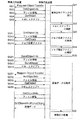
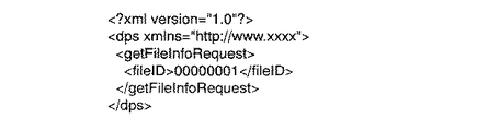
そして、画像出力装置1では、通信制御部12が、DPSプロトコルに従って、取得したオブジェクトIDで画像データファイルを指定してXMLスクリプトのファイル情報取得コマンドDPS_GetFileInfoを送信する。
【0212】
図17は、画像出力システムの参考構成例2において使用されるファイル情報取得コマンドDPS_GetFileInfoのXMLスクリプトの一例を示す図である。図17において、getFileInfoRequestタグは、ファイル情報取得コマンドであることを示すタグである。図17においては、getFileInfoRequestタグの下位に、fileIDタグが配置される。fileIDタグは、ファイル情報取得の対象のファイルのオブジェクトIDを指定するためのタグである。
【0213】
画像出力装置1の通信制御部12は、そのDPSプロトコルのファイル情報取得コマンドDPS_GetFileInfoを、画像転送プロトコルのファイル情報取得コマンドGetObjectInfoに変換し、送信する。このコマンドは、USB層および物理層を介して画像供給装置2に伝送される。
【0214】
画像供給装置2では、通信制御部22が、画像転送プロトコルに従って、コマンドGetObjectInfoを受信すると、指定されたオブジェクトIDのファイルのファイル情報を送信する。このファイル情報は、USB層および物理層を介して画像出力装置1に伝送される。
【0215】
画像出力装置1では、通信制御部12が、画像転送プロトコルに従ってそのファイル情報を受信すると、そのファイル情報をXMLスクリプトとして記述し、DPSプロトコル層に渡す。
【0216】
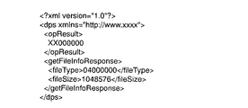
図18は、画像出力システムの参考構成例2において使用されるファイル情報取得コマンドDPS_GetFileInfoの応答のXMLスクリプトの一例を示す図である。図18において、opResultタグは、オブジェクトID取得コマンドの処理結果コードを指定するためのタグである。また、getFileInfoResponseタグは、ファイル情報取得コマンドの処理結果の戻り値を指定するためのタグである。図18においては、getFileInfoResponseタグの下位に、fileTypeタグおよびfileSizeタグが配置される。fileTypeタグは、ファイル情報のうちのファイルの形式を指定するためのタグである。fileSizeタグは、ファイル情報のうちのファイルサイズを指定するためのタグである。なお、ファイル形式は、各形式に予め割り当てられている番号により指定される。
【0217】
次に、画像出力装置1では、通信制御部12が、DPSプロトコルに従って、取得したオブジェクトIDで画像データファイルを指定してXMLスクリプトのファイル取得コマンドDPS_GetFileを送信する。通信制御部12は、そのDPSプロトコルのファイル取得コマンドDPS_GetFileを、画像転送プロトコルのファイル取得コマンドGetObjectに変換し、送信する。このコマンドは、USB層および物理層を介して画像供給装置2に伝送される。
【0218】
なお、ファイル全体を取得するファイル取得コマンドDPS_GetFileの代わりに、ファイルの一部を取得するファイル部分取得コマンドDPS_GetPartialFileを複数回送信してファイル全体を取得するようにしてもよい。このファイル部分取得コマンドDPS_GetPartialFileは、画像転送プロトコルのコマンドGetPartialObjectに変換される。
【0219】
画像供給装置2では、通信制御部22が、画像転送プロトコルに従って、コマンドGetObjectを受信すると、指定されたオブジェクトIDのファイル(画像データファイル31)を読み出し、送信する。このファイルは、USB層および物理層を介して画像出力装置1に伝送される。
【0220】
画像出力装置1では、通信制御部12が、画像転送プロトコルに従ってそのファイルを受信すると、DPSプロトコル層においてもそのファイルを受信したこととなる。
【0221】
ここで、画像出力装置1が図3および図4に示すプリンタであり、かつ画像供給装置2が図5および図6に示すデジタルカメラである場合、この画像データの取得には、画像出力装置1におけるDPSプロトコル処理機能52および通信制御機能51、並びに、画像供給装置2における通信制御機能81およびファイルシステム管理機能83が使用される。
【0222】
そして、画像出力装置1は、画像データを取得すると、その画像データに基づく画像を出力する(ステップS26)。その際、画像出力装置1では、出力制御部13および出力機構14が、画像出力処理を行う。
【0223】
ここで、画像出力装置1が図3および図4に示すプリンタである場合、画像出力処理には、画像処理機能53、印刷データ生成機能54および印刷制御機能55が使用される。
【0224】
このように、この参考構成例2では、画像供給装置2に格納されたジョブ指定ファイルが画像出力装置1に転送され、画像出力装置1がジョブ指定ファイルを解釈し、ジョブを実行する。また、他の実施例として、画像供給装置2が、ジョブ指定ファイルを解釈し、そのジョブ指定ファイルの内容に従ってジョブ開始コマンドを生成し、画像出力装置1に送信し、画像出力装置1が、そのジョブ開始コマンドを解釈してジョブを実行するようにしてもよい。
【0225】
なお、この画像出力システムの参考構成例2は、後述の実施の形態のいずれとも組み合わせ可能である。
【0226】
以上のように、上記画像出力システムの参考構成例2によれば、画像供給装置2が、画像データおよび印刷ジョブを指定するジョブ指定ファイル(ここでは、DPOFのAUTPRINT.MRKファイル)を格納し、画像出力装置1が、そのジョブ指定ファイルを取得し、指示されたジョブを解釈し、そのジョブ指定ファイルの情報に基づいて、マークアップ言語で記述した画像出力に係る制御情報を生成する。これにより、DPOF方式などの既存のジョブ指定ファイルを使用でき、簡単に複雑な印刷ジョブを実行することができる。
【0227】
さらに、上記画像出力システムの参考構成例2によれば、画像供給装置2は、画像出力対象の1または複数の画像データおよびジョブ指定ファイルのいずれか一方を印刷ジョブ開始コマンドにおいて指定することができる。画像出力装置1は、印刷ジョブ開始コマンドにおいて画像データが指定された場合には、その印刷ジョブ開始コマンドに従って画像供給装置2からその画像データを取得し、印刷ジョブ開始コマンドにおいてジョブ指定ファイルが指定された場合には、その印刷ジョブ開始コマンドに従って画像供給装置2からそのジョブ指定ファイルを取得し、そのジョブ指定ファイルにおいて指定された画像データを画像供給装置2から取得する。これにより、画像データごとに、あるいはジョブ指定ファイルで纏めて、画像出力の対象となる画像データを指定することができ、様々なパターンの印刷ジョブを行うことができる。
【0228】
実施の形態1.
本発明の実施の形態1に係る画像出力システムは、上記参考構成例1または2に係る画像出力システムにおいて自律復旧できない障害(例えば紙送り機構の障害である紙ジャム、電源の正常オフまたは異常遮断といった電源断、通信ケーブルの切断または脱落といった通信路切断など)から復旧した際のリカバリ処理を行うようにしたものである。
【0229】
この実施の形態1に係る画像出力システムでは、画像出力装置1が、画像出力としての印刷処理におけるページレイアウト内の所定位置(最初、最後など)に割り当てられた印刷対象を示す再開情報を画像供給装置2に送信し、障害により印刷処理が中止された後に、印刷処理を新たに開始させる印刷ジョブ開始コマンドとともに、再開時の最初の印刷対象を指定する制御情報を画像供給装置2から受信し、その印刷対象から印刷処理を再開する。その一方で、画像供給装置2が、その再開情報を受信して記憶しておき、印刷処理を再開する場合に、印刷処理を新たに開始させる印刷ジョブ開始コマンドとともに、最後に記憶した再開情報を制御情報として画像出力装置1へ送信する。
【0230】
なお、実施の形態1における画像出力装置1および画像供給装置2の基本的な構成は、画像出力システムの参考構成例1の場合と同様であるが、リカバリ処理に係る下記の機能が追加される。
【0231】
次に、上記システムにおける各装置の動作について説明する。
【0232】
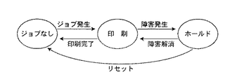
図19は、実施の形態1に係る画像出力システムにおける画像出力装置についての状態遷移図である。
【0233】
図19に示すように、画像出力装置1は、印刷ジョブがないと、ジョブなし状態(すなわち、アイドル状態)にあり、画像供給装置2から印刷ジョブを供給されると、印刷状態に移行し、印刷処理を行う。そして、印刷ジョブが終了し、後続の印刷ジョブがないと、画像出力装置1は、ジョブなし状態に移行する。なお、この状態の管理は、画像出力装置1の出力制御部13により行われる。
【0234】
印刷状態において障害が発生すると、画像出力装置1は、ホールド状態に移行し、印刷処理を中断する。自律復旧可能な障害の場合には、障害がなくなると、画像出力装置1は、印刷状態に戻り、中断した印刷処理を再開する。一方、紙ジャム、通信路切断などの自律復旧不能な障害の場合には、画像出力装置1は、リセット指令があるまでホールド状態のままとなり、リセット指令があると、中断した印刷ジョブを廃棄して、ジョブなし状態に移行する。その時に残りの印刷ジョブがある場合やその後に新たな印刷ジョブが発生した場合には、画像出力装置1は、印刷状態に移行する。
【0235】
また、画像出力装置1の電源が断たれた場合、画像出力装置1における印刷ジョブが消失するので、その後、電源が投入された場合には、画像出力装置1は、ジョブなし状態となる。
【0236】
次に、リカバリ処理について説明する。なお、リカバリ処理の手順は、下記に示すように、障害の種類などに応じて、複数種類のいずれかとすることができる。
【0237】
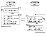
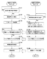
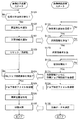
まず、紙ジャム、通信路切断、電源の正常断、電源の異常断などの自律復旧不能な障害が発生した場合のリカバリ処理の一例について説明する。図20は、実施の形態1に係る画像出力システムの正常時の印刷処理において行われる、リカバリのための処理を説明するフローチャートである。図21は、実施の形態1に係る画像出力システムのリカバリ処理の一例について説明するフローチャートである。
【0238】
まず、印刷状態において、画像出力装置1は、印刷ジョブ開始コマンドにおいて指定されたページレイアウトおよび画像に基づいてそのページレイアウトにその画像を順次割り当てて印刷処理を実行するが、その際、あるページから次ページへの切り換わりを検出すると(ステップS101)、切換後のページ最初でのジョブ状態情報を画像供給装置2に送信する。
【0239】
実施の形態1では、画像出力装置1は、切換後のページのページレイアウトの最初に使用される画像データを指定している印刷ジョブのジョブID(DPOFの「PRT PID」の値に相当するもの)、その画像データの格納場所のパス(DPOFの「IMG SRC」の値に相当するもの)、および繰り返し供給回数(DPOFの「PRT QTY」の値に相当するもの)を再開情報(リカバリ処理で使用されるジョブ状態情報)として画像供給装置2に送信する(ステップS102)。
【0240】
その際、出力制御部13が、再開情報を纏め、通信制御部12に供給し、通信制御部12が、通信回路11を制御して、その再開情報を制御情報として画像供給装置2に送信する。
【0241】
例えば、1ページ内に画像を1つ配置するページレイアウトの場合に、図12に示すジョブ指定ファイルに基づいて画像を印刷するときには、まず、第1ページの印刷が終わり第2ページの印刷が開始されると、画像出力装置1は、ジョブID「001」、画像データのファイルパス「./DCIM/100EPSON/IMAGE01.JPG」および繰り返し供給回数「002」を含む再開情報を画像供給装置2に送信する。また、その場合において、第2ページの印刷が終わり第3ページの印刷が開始されると、画像出力装置1は、ジョブID「002」、画像データのファイルパス「./DCIM/100EPSON/IMAGE02.JPG」および繰り返し供給回数「001」を含む再開情報を画像供給装置2に送信する。
【0242】
なお、この実施の形態1では、画像出力装置1の通信制御部12が、ページの切り換わりが発生すると、DPSプロトコルに従って、その時点でのジョブ状態情報を通知するジョブ状態通知コマンドDPS_NotifyJobStatusのXMLスクリプトを生成し、送信する。コマンドDPS_NotifyJobStatusのXMLスクリプトでは、ジョブIDを示すタグ<prtPid>,</prtPid>でジョブIDの値が囲まれ、画像データの格納場所のパスを示すタグ<imagePath>,</imagePath>で画像データの格納場所のパスの値が囲まれ、繰り返し供給回数を示すタグ<copyId>,</copyId>で繰り返し供給回数の値が囲まれる。
【0243】
図22は、実施の形態1において使用されるジョブ状態通知コマンドDPS_NotifyJobStatusのXMLスクリプトの一例を示す図である。図22において、notifyJobStatusRequestタグは、ジョブ状態通知コマンドであることを示すタグである。図22においては、notifyJobStatusRequestタグの下位に、jStatusタグ、prtPidタグ、imagePathタグ、copyIdタグ、progressタグおよびjEndReasonタグが配置される。
【0244】
なお、ジョブ指定ファイルが使用される場合には、prtPidタグ、imagePathタグおよびcopyIdタグで指定される値には、画像出力装置1により取得されたDPOFのジョブ指定ファイルAUTPRINT.MRKにおける値が使用され、その時点で処理中のジョブのジョブID、画像データのパスおよび繰り返し供給回数の値が設定される。
【0245】
また、jStatusタグは、ジョブの状態が印刷状態、ジョブなし状態およびホールド状態のいずれであるかを指定するためのタグである。progressタグは、ジョブにおける全ページ数Tと、印刷中のページ番号NとをN/Tの書式で指定するためのタグである。jEndReasonタグは、正常終了、ユーザ操作による終了、異常終了などの、ジョブが終了した原因を示す値を指定するためのタグである。なお、ジョブなし状態にある場合に、jEndReasonタグにより値が指定される。
【0246】
なお、図22に示すスクリプトでは、prtPidタグ、imagePathタグおよびcopyIdタグにより、ジョブID、イメージパスおよび繰り返し供給回数が指定されるが、その代わりに、ジョブ指定ファイルが使用されない場合には、ジョブ開始コマンドにおけるimageIDタグで指定された画像データおよびcopiesタグで指定された繰り返し供給回数が、ジョブ状態通知コマンドにおいて使用されるようにしてもよい。
【0247】
一方、画像供給装置2は、画像出力装置1から、ページの切り換わりごとに、ジョブID、ページ最初の画像データの格納場所のパス、その画像データの繰り返し供給回数などといった再開情報を受信すると(ステップS111)、それらを記憶し、画像出力装置1から通知された最新の再開情報を保持する(ステップS112)。
【0248】
この実施の形態1では、画像供給装置2の通信制御部22が、DPSプロトコルに従って、ページごとに、コマンドDPS_NotifyJobStatusであるXMLスクリプトを受信し、そのXMLスクリプトから、ジョブID、画像データの格納場所のパス、および画像データの繰り返し供給回数を抽出し、記憶する。
【0249】
このようにして、画像供給装置2は、印刷処理が開始されたページごとに、所定の位置(ここでは最初)の画像データを指定している印刷ジョブのジョブID、その画像データの格納場所のパス、その画像データの繰り返し供給回数などといった再開情報を順次記憶していく。なお、画像供給装置2に記憶される再開情報は、最新のものだけあればよく、古いものは消去してもよい。
【0250】
そして、印刷状態において、紙ジャム、電源オフ操作などの自律復旧不能な障害が発生した場合(ステップS121)、画像出力装置1は、ホールド状態に移行し、障害発生を画像供給装置2に通知する(ステップS122)。
【0251】
この実施の形態1では、画像出力装置1の通信制御部12が、障害が発生すると、DPSプロトコルに従って、装置の状態を通知するコマンドDPS_NotifyDeviceStatusのXMLスクリプトを生成し、送信する。コマンドDPS_NotifyDeviceStatusのXMLスクリプトでは、障害の状態を示すタグ<errorStatus>,</errorStatus>で障害状態を示す値が囲まれ、障害の原因を示すタグ<reason>,</reason>で障害原因を示す値が囲まれる。
【0252】
図23は、実施の形態1において使用されるデバイス状態通知コマンドDPS_NotifyDeviceStatusのXMLスクリプトの一例を示す図である。図23において、notifyDeviceStatusRequestタグは、デバイス状態通知コマンドであることを示すタグである。図23においては、notifyDeviceStatusRequestタグの下位に、errorStatusタグ、reasonタグ、disconnectEnableタグおよびcapabilityChangeタグが配置される。
【0253】
errorStatusタグは、障害なし、復旧可能障害、復旧不能障害などの障害状態を指定するためのタグである。reasonタグは、障害なし、用紙関係の障害、インク関係の障害、ハードウェア関係の障害、データ関係の障害などといった障害の原因を指定するためのタグである。disconnectEnableタグは、接続を解除してよいか否かを指定するためのタグである。capabilityChangeタグは、画像出力装置1で許容される印刷条件に変更があったか否かを指定するためのタグである。
【0254】
画像供給装置2は、画像出力装置1から、障害発生の通知を受信すると(ステップS131)、画像出力装置1から通知された最新の再開情報(ジョブID、ページ最初の画像データの格納場所のパス、その画像データの繰り返し供給回数など)を読み出す(ステップS132)。
【0255】
この実施の形態1では、画像供給装置2の通信制御部22が、DPSプロトコルに従って、上述のコマンドDPS_NotifyDeviceStatusのXMLスクリプトを受信し、そのXMLスクリプトから障害状態を認識する。
【0256】
そして、画像供給装置2は、印刷ジョブ開始時に先に送信した印刷ジョブ開始コマンドに、最新の再開情報を追加して送信する(ステップS133)。
【0257】
この実施の形態1では、画像供給装置2の通信制御部22が、DPSプロトコルに従って、最新のジョブID、ページ最初の画像データの格納場所のパス、およびその画像データの繰り返し供給回数を設定した上述のコマンドDPS_StartJobのXMLスクリプトを送信する。
【0258】
図24は、実施の形態1において、ジョブ再開時の印刷ジョブ開始コマンドDPS_StartJobのXMLスクリプトの一例を示す図である。図24に示すように、ジョブ再開時の印刷ジョブ開始コマンドDPS_StartJobでは、imageIDタグにより、ジョブ指定ファイルのオブジェクトID(ここでは、00000002)が指定され、再開位置を示すジョブID、ページ最初の画像データの格納場所のパスおよびその画像データの繰り返し供給回数が、prtPidタグ、imagePathタグおよびcopiesタグによりそれぞれ指定される。
【0259】
画像出力装置1は、その印刷ジョブ開始コマンドを受信すると(ステップS124)、その印刷ジョブ開始コマンドにおいて指定された、先に使用されたジョブ指定ファイルの送信要求を送信する。
【0260】
この実施の形態1では、画像出力装置1の通信制御部12が、DPSプロトコルに従って、XMLスクリプトのジョブ開始コマンドDPS_StartJobを受信し、ジョブ指定ファイルを指定してファイル取得コマンドDPS_GetFileを発行する。
【0261】
そして、画像供給装置2は、そのジョブ指定ファイルの送信要求に応じて、ジョブ指定ファイルを送信する(ステップS134)。画像出力装置1は、そのジョブ指定ファイルを受信する(ステップS125)。
【0262】
この実施の形態1では、画像出力装置1の通信制御部12が、DPSプロトコルにおけるファイル取得コマンドDPS_GetFileを発行し、画像供給装置2からジョブ指定ファイルを取得する。
【0263】
画像出力装置1は、ジョブ指定ファイルの内容を参照し、印刷ジョブ開始コマンドにより指定されたジョブID、ページ最初の画像データの格納場所のパス、およびその画像データの繰り返し供給回数に該当する位置をジョブ指定ファイル内で発見すると、その位置を印刷ジョブの再開位置と特定する(ステップS126)。
【0264】
そして、画像出力装置1は、その再開位置から印刷ジョブを再開し(ステップS127)、必要に応じて画像データを画像供給装置2から取得する(ステップS127,S135)。
【0265】
これにより、障害発生により中断した印刷ジョブがユーザなどによるリセット指令後に再開され、障害が発生したページの先頭から印刷が再開される。図25は、実施の形態1に係る画像出力システムにおける印刷再開を説明する図である。例えば図25に示すように、画像101a,画像101cの印刷後、途中で画像101b,101dを印刷している時に障害が発生した場合にも、ページの最初に割り当てられる画像101aについてのジョブID、パスおよび繰り返し供給回数に基づいてジョブ指定ファイル内での印刷再開位置が特定されて印刷ジョブが再開される。
【0266】
なお、図25のように1つのページに複数の画像が配置される場合、印刷ジョブにおける出現順番が最も早い画像についてジョブIDなどが記憶され、その画像から印刷が再開される。例えば図12に示すジョブ指定ファイルで図25に示すような1ページに4つの画像が割り当てられるレイアウトとした場合、画像101aに割り当てられるIMAGE01.JPGについてのジョブID「001」、パス「./DCIM/100EPSON/IMAGE01.JPG」、繰り返し回数「002」が再開情報として記憶される。そして、図25に示す位置で障害が発生したときには、その再開情報が指定する図12の最初のジョブから同一のレイアウトで印刷が再開される。
【0267】
なお、画像出力装置1は、印刷対象の繰り返し供給の途中で改ページが発生した場合には、画像供給装置2に通知する繰り返し供給回数の値を残りの繰り返し供給回数に変更し、変更後の値を通知する。これにより、画像供給装置2では、印刷対象の繰り返し供給の途中で改ページが発生した場合には、記憶する繰り返し供給回数が残りの繰り返し供給回数に変更される。この場合には、画像出力装置1がジョブIDとファイルパスでジョブ再開位置を特定するようにするか、画像供給装置2が画像出力装置1へ送信するジョブ指定ファイル内の該当する繰り返し供給回数を同様に変更する。
【0268】
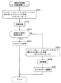
次に、通信路3の切断および画像出力装置1の電源の異常断が発生した場合のリカバリ処理の一例について説明する。図26は、本発明の実施の形態1に係る画像出力システムのリカバリ処理の他の一例について説明するフローチャートである。なお、この場合の正常動作時の処理は、上述の場合(図20)と同様である。
【0269】
まず、通信路3の切断または画像出力装置1の電源の異常断が発生すると(ステップS141)、画像出力装置1と画像供給装置2との間の通信コネクションが切れるため、画像供給装置2は、その通信コネクション(例えばUSBのコネクション)の切断を検知する(ステップS151)。
【0270】
その後、通信路3や電源が復旧すると、画像出力装置1は、リセットまたは再起動する(ステップS123)。そして、通信路3を介して通信コネクションが確立されると、画像供給装置2は、画像出力装置1との接続が復旧したことを検知する(ステップS152)。
【0271】
画像供給装置2は、接続が復旧すると、上述したように、印刷ジョブ開始コマンドとともに再開情報を画像出力装置1に送信し、画像出力装置1は、それに応じて印刷ジョブを再開する。
【0272】
以上のリカバリ処理の例の場合では、画像出力装置1が、ページごとに、再開情報を画像供給装置2に送信しているが、その代わりに、画像出力装置1が、紙ジャムなどの障害を検出した場合に、自動的に、再開情報を画像供給装置2に送信するようにしてもよい。次にその場合について説明する。
【0273】
図27は、本発明の実施の形態1に係る画像出力システムのリカバリ処理のさらに他の一例について説明するフローチャートである。なお、この場合には、上述の場合(図20)のような正常動作時の処理は特に必要なく、障害発生時に、再開情報が画像出力装置1から画像供給装置2へ伝送される。
【0274】
このリカバリ処理の場合、図27に示すように、障害が発生すると、画像出力装置1は、障害発生を通知し(ステップS122)、再開情報を画像供給装置2に送信する(ステップS161)。
【0275】
例えば、1ページ内に画像を1つ配置するページレイアウトの場合において、図12に示すジョブ指定ファイルに基づいて第2ページの印刷中に障害が発生すると、画像出力装置1は、ジョブID「001」、画像データのファイルパス「./DCIM/100EPSON/IMAGE01.JPG」および繰り返し供給回数「002」を含む再開情報を画像供給装置2に送信する。
【0276】
また、例えば、同一のレイアウトおよびジョブ指定ファイルを使用して、第3ページの印刷中に障害が発生した場合には、画像出力装置1は、ジョブID「002」、画像データのファイルパス「./DCIM/100EPSON/IMAGE02.JPG」および繰り返し供給回数「001」を含む再開情報を画像供給装置2に送信する。
【0277】
そして、画像供給装置2は、その障害発生の通知を受信し(ステップS131)、再開情報を受信すると(ステップS171)、それを保持して(ステップS172)、画像出力装置1が復旧するまで待機する(ステップS173)。
【0278】
画像出力装置1がリセットや再起動により復旧すると(ステップS123)、画像供給装置2は、画像出力装置1の復旧を検知し、印刷ジョブ開始コマンドとともに再開情報を画像出力装置1に送信する(ステップS174)。画像出力装置1は、その印刷ジョブ開始コマンドおよび再開情報に基づいて、上述のようにして印刷ジョブを再開する。
【0279】
なお、この実施の形態1では、印刷再開位置を示す再開情報として、ジョブID、パスおよび繰り返し供給回数の3つを使用しているが、正確に印刷再開位置を特定できれば、これらのうちの1つだけまたは2つだけでもよい。また、他のジョブ状態情報を再開情報に使用してもよい。
【0280】
さらに、この実施の形態1では、ページレイアウトの最初の画像データに関するジョブ状態情報を再開情報に使用しているが、ページレイアウトの最後の画像データに関するジョブ状態情報を再開情報に使用するようにしてもよい。その場合には、画像出力装置1により、一連の印刷ジョブにおいて再開情報に合致する位置の次の画像から印刷ジョブが再開される。
【0281】
以上のように、上記実施の形態1によれば、画像供給装置2は、一連の複数の画像を印刷する印刷処理を新たに開始させる印刷ジョブ開始コマンドとともに、一連の複数の画像のうちの印刷処理開始時の画像を指定する開始情報(ここでは再開情報)を画像出力装置1へ送信する。一方、画像出力装置1は、印刷ジョブ開始コマンドとともに開始情報を画像供給装置2から受信すると、その開始情報により指定された画像(開始情報に名称を記述された画像またはその次の画像)から印刷処理を開始する。
【0282】
これにより、開始情報として印刷処理の開始位置を簡単に指定でき、画像データそのものを画像出力装置1へ送信し画像出力装置1において画像データから印刷制御データを生成し画像を印刷する印刷処理における障害からのリカバリ処理を良好に実行することができる。
【0283】
さらに、上記実施の形態1によれば、画像供給装置1が、印刷ジョブ開始コマンド内で、印刷対象となる一連の複数の画像および印刷処理開始時の画像を指定することができる。
【0284】
これにより、印刷ジョブ開始コマンドを再利用でき、リカバリ処理を簡単に実行することができる。
【0285】
さらに、上記実施の形態1によれば、画像供給装置1が、一連の複数の画像データおよび印刷ジョブを指定するジョブ指定ファイルを格納し、印刷ジョブ開始コマンド内で、ジョブ指定ファイルおよび印刷処理開始時の画像を指定することができる。
【0286】
これにより、印刷ジョブ開始コマンドおよびジョブ指定ファイルを再利用でき、リカバリ処理を簡単に実行することができる。
【0287】
また、上記実施の形態1によれば、画像出力装置1は、ページレイアウト内の所定位置(最初または最後)に割り当てられた画像を示す再開情報を画像供給装置2に送信し、障害により印刷処理が中止された後に、印刷処理を新たに開始させる印刷ジョブ開始コマンドとともに再開情報を画像供給装置2から受信し、その再開情報により指定された画像(上記所定位置が最初である場合には再開情報に名称を記述された画像、上記所定位置が最後である場合にはその次の画像)から印刷処理を再開する。画像供給装置2は、画像出力装置1からの再開情報を受信して記憶し、印刷処理を再開する場合に、印刷処理を新たに開始させる印刷ジョブ開始コマンドとともに最新の再開情報を画像出力装置1へ送信する。
【0288】
これにより、画像データそのものを画像出力装置1へ送信し画像出力装置1において画像データから印刷制御データを生成し画像を印刷する印刷処理における障害からのリカバリ処理を良好に実行することができる。
【0289】
さらに、上記実施の形態1によれば、画像出力装置1が、障害発生後、印刷ジョブ開始コマンドの受信前に、障害発生時の印刷処理に関するデータを当該画像出力装置1から消去してもよい。
【0290】
これにより、画像出力装置1が、確実に、印刷処理再開時に新たに受信した印刷ジョブ開始コマンドに基づいて動作することとなり、正確にリカバリ処理を実行することができる。
【0291】
さらに、上記実施の形態1によれば、画像供給装置2が、印刷処理を再開する場合に送信する印刷ジョブ開始コマンドを、障害発生時の印刷処理を開始させる際に送信した印刷ジョブ開始コマンドに最新の再開情報を追加したものとすることができる。
【0292】
これにより、印刷ジョブ開始コマンドを再利用でき、リカバリ処理を簡単に実行することができる。
【0293】
さらに、上記実施の形態1によれば、画像出力装置1が、障害を検出した場合にのみ再開情報を画像供給装置2に送信するようにしてもよい。
【0294】
これにより、再開情報を頻繁に送受する必要がないため、正常動作時の処理を増加させることなく、復旧後に印刷処理を正確に再開することができる。
【0295】
さらに、上記実施の形態1によれば、画像出力装置1が、ページごとに再開情報を画像供給装置に送信するようにしてもよい。
【0296】
これにより、障害発生時に再開情報の送信が困難な場合でも、復旧後に印刷処理を正確に再開することができる。
【0297】
さらに、上記実施の形態1によれば、ページレイアウト内の所定位置に割り当てられた画像の属する印刷ジョブのジョブID、画像供給装置内のその画像の格納場所を示す情報、およびその画像の繰り返し供給回数のうちの少なくとも1つを含む再開情報が使用される。
【0298】
これにより、画像出力装置1において、再開時の最初の印刷対象が正確に特定され、復旧後に印刷処理を正確に再開することができる。
【0299】
さらに、上記実施の形態1によれば、画像出力装置1または画像供給装置2が、再開情報として画像の繰り返し供給回数を少なくとも使用し、画像の繰り返し供給の途中で改ページが発生した場合には、繰り返し供給回数を残りの繰り返し供給回数に変更する。
【0300】
これにより、繰り返し供給回数が複数に設定されている場合でも、復旧後に印刷処理を正確に再開することができる。
【0301】
さらに、上記実施の形態1によれば、画像出力装置1が、障害を検知すると、その旨を画像供給装置2に通知し、その後、印刷処理を中止する。画像供給装置2は、障害検知の通知の受信後、所定の指令を受け付けると、印刷処理の再開のために再開情報を送信する。
【0302】
これにより、確実に復旧した後に所定の指令に呼応して印刷が再開され、復旧後に印刷処理を正確に再開することができる。
【0303】
さらに、上記実施の形態1によれば、画像供給装置2が、画像データおよび印刷ジョブを指定するジョブ指定ファイルを格納し、印刷処理を再開する場合に、印刷ジョブ開始コマンド内でジョブ指定ファイルを指定し、印刷ジョブ開始コマンドに再開情報を追加する。
【0304】
これにより、印刷ジョブ開始コマンドおよびジョブ指定ファイルを再利用でき、リカバリ処理を簡単に実行することができる。
【0305】
さらに、上記実施の形態1によれば、1または複数の印刷ジョブを指定し、各ジョブに対して指定される印刷条件情報を有するジョブ指定ファイルが使用される。
【0306】
これにより、既存のジョブ指定ファイルを使用して複雑な印刷ジョブを簡単に実行することができ、その場合でもリカバリ処理を良好に実行することができる。
【0307】
さらに、上記実施の形態1によれば、画像出力装置1が、紙送り機構の障害を検出した場合に、再開情報を画像供給装置2に送信する。
【0308】
これにより、紙送り機構の障害が解消された後のリカバリ処理を良好に実行することができる。
【0309】
さらに、上記実施の形態1によれば、画像供給装置2が、画像出力装置1の電源供給に障害が発生したことを検知した場合、画像出力装置2の電源供給が復旧したことを検知した後に、印刷ジョブ開始コマンドとともに最新の再開情報を画像出力装置1へ送信する。
【0310】
これにより、電源供給の障害が解消された後のリカバリ処理を良好に実行することができる。
【0311】
さらに、上記実施の形態1によれば、画像供給装置2が、画像出力装置1との間の通信路3に障害が発生したことを検知した場合、通信路3が復旧したことを検知した後に、印刷ジョブ開始コマンドとともに最新の再開情報を画像出力装置1へ送信する。
【0312】
これにより、通信路3の障害が解消された後のリカバリ処理を良好に実行することができる。
【0313】
実施の形態2.
本発明の実施の形態2に係る画像出力システムは、実施の形態1で示したように、一方の電源が切られた後や通信路3が切断された後に、通信相手との通信が回復した際の、通信中断前後での通信相手の同一性を判断し、同一の通信相手との通信を再開し、リカバリ処理により印刷処理を継続するようにしたものである。
【0314】
実施の形態2では、画像出力装置1は、通信路3を介して接続されている画像供給装置2の通信プロトコル上で固有な識別子を記憶し、電源が切れた場合、電源復旧後に通信路3を介して接続されている画像供給装置2の通信プロトコル上で固有な識別子を取得し、その識別子に基づいて画像供給装置2の同一性を判断する。
【0315】
なお、通信プロトコル上で固有な識別子は、MAC(Medium Access Control )アドレスやそれに準じたものなど、通信回路11,21に割り当てられているものであり、不揮発性メモリ、バックアップ電源に接続された揮発性メモリ、磁気記録媒体などの、電源が切れていても記憶内容を保持する記録媒体に記憶される。
【0316】
また、画像供給装置2は、通信路3を介して接続されている画像出力装置1の通信プロトコル上で固有な識別子を記憶し、電源が切れた場合、電源復旧後に通信路3を介して接続されている画像出力装置1の通信プロトコル上で固有な識別子を取得し、その識別子に基づいて画像出力装置1の同一性を判断する。
【0317】
また、画像出力装置1は、通信路3を介して接続されている画像供給装置2の通信プロトコル上で固有な識別子を記憶し、例えば通信路3の接続コネクタが画像出力装置1または画像供給装置2の接続コネクタから外されたりして通信路3が切断された場合、通信路3の接続が復旧した後に、通信路3を介して接続されている画像供給装置2の通信プロトコル上で固有な識別子を取得し、その識別子に基づいて上記画像供給装置の同一性を判断する。
【0318】
また、画像供給装置2は、通信路3を介して接続されている画像出力装置1の通信プロトコル上で固有な識別子を記憶し、例えば通信路3の接続コネクタが画像出力装置1または画像供給装置2の接続コネクタから外されたりして通信路3が切断された場合、通信路3の接続が復旧した後に、通信路3を介して接続されている画像出力装置1の通信プロトコル上で固有な識別子を取得し、その識別子に基づいて画像出力装置1の同一性を判断する。
【0319】
なお、これらの処理は,通信制御部12,22により実行され、通信相手の識別子は、画像出力装置1および画像供給装置2における図示せぬメモリにそれぞれ記憶される。
【0320】
また、この実施の形態2に係る画像出力システムは、他の実施の形態のいずれとも組み合わせ可能である。
【0321】
この実施の形態2に係る画像出力システムでは、画像出力装置1および画像供給装置2が、上述の機能を有し、障害および復旧の前後での通信相手の同一性が認められるときにのみ、実施の形態1で述べたようにしてリカバリ処理を行う。一方、同一性が認められないときには、画像供給装置2は、印刷ジョブの再開のための処理を行わずに、全く新しい印刷ジョブの開始コマンドを発行するようにしてもよい。
【0322】
以上のように、上記実施の形態2によれば、画像供給装置2が、通信路3を介して接続されている画像出力装置1の通信プロトコル上で固有な識別子を記憶しておき、通信路3および/または電源の障害からの復旧後に通信路3を介して接続される画像出力装置1の通信プロトコル上で固有な識別子を取得し、その識別子に基づいて画像出力装置1の同一性を判断する。
【0323】
これにより、障害発生時の通信相手だった画像出力装置1を正確に特定することができ、同一の画像出力装置1を使用して、リカバリ処理を良好に実行することができる。
【0324】
さらに、上記実施の形態2によれば、画像出力装置1が、通信路3を介して接続されている画像供給装置2の通信プロトコル上で固有な識別子を記憶しておき、通信路3および/または電源の障害からの復旧後に通信路3を介して接続される画像供給装置2の通信プロトコル上で固有な識別子を取得し、その識別子に基づいて画像供給装置2の同一性を判断する。
【0325】
これにより、障害発生時の通信相手だった画像供給装置2を正確に特定することができ、同一の画像供給装置2からの印刷ジョブ開始コマンドに基づいて、リカバリ処理を良好に実行することができる。
【0326】
実施の形態3.
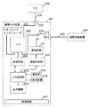
本発明の実施の形態3に係る画像出力システムは、複数の画像出力装置1−1〜1−nを有し、ある画像出力装置1−jによる印刷処理中に上述のような障害が発生した場合に、代替の画像出力装置1−kを探し、代替の画像出力装置1−kにより印刷処理を継続するようにしたものである。
【0327】
図28は、本発明の実施の形態3に係る画像出力システムの構成を示すブロック図である。図28において、画像出力装置1−i(i=1,・・・,n)は、上述の画像出力装置1と同様の装置であって、通信路3−iに対応した通信回路11を有する。
【0328】
また、画像供給装置2−1は、上述の画像供給装置2と同様の装置であり、上述の画像供給装置2の通信回路21として、複数の画像出力装置1−1〜1−nに有線通信路3−1または無線通信路3−2〜3−nを介して接続可能な1または複数の通信回路21−1〜21−nを備え、いずれかの通信回路21−kにより、印刷ジョブ開始コマンドと再開情報を、障害の発生した画像出力装置1−jとは別の画像出力装置1−k(k≠j)へ送信する。なお、その際に別の画像出力装置1−k(k≠j)へ送信する再開情報は、実施の形態1で述べたものとされ、実施の形態1で述べたように印刷が再開される。これにより、復旧が困難な場合でも別の画像出力装置1−kで正確に印刷を再開することができる。また、復旧を待たずに直ちに別の画像出力装置1−kで正確に印刷を再開することができる。
【0329】
例えば、画像供給装置2−1は、画像出力装置1−1による印刷処理中の障害が発生した場合には、残りの画像出力装置1−2〜1−nのうちのいずれかを選択し、いずれかの通信回路21−kにより、印刷再開時の最初の印刷対象を指定する再開情報を送信する。その再開情報を受信した画像出力装置1−kは、その情報に基づいて、印刷ジョブ内の再開位置を特定し、その位置から印刷処理を開始する。
【0330】
なお、画像供給装置2−1は、複数の画像出力装置1−2〜1−nのうち、自己の使用する画像出力制御プロトコル(例えば上述のDPSプロトコル、PTPなど)を解釈可能な画像出力装置1−rを選択し、その画像出力装置1−rへ再開情報を送信するようにしてもよい。
【0331】
また、画像供給装置2−1は、複数の画像出力装置1−2〜1−nのうち、再開情報に基づいて印刷処理を再開することができる画像出力装置1−rを選択し、その画像出力装置1−rへ再開情報を送信するようにしてもよい。
【0332】
また、画像供給装置2−1は、複数の画像出力装置1−2〜1−nのうち、中断された印刷ジョブで指定された印刷条件で印刷可能な画像出力装置1−rを選択し、その画像出力装置1−rへ再開情報を送信するようにしてもよい。これにより、別の画像出力装置を使用しても、元の画像出力装置と同様な印刷状態で印刷を再開することができる。そのような印刷条件としては、用紙サイズ、用紙タイプ、ベンダ固有の色補正処理、フレーム画像重畳印刷(画像データによる画像に、フレーム画像を重畳させて印刷するもの)などがある。
【0333】
なお、画像供給装置2−1は、画像出力装置1−2〜1−nに対して、具備する印刷機能や通信機能の情報の送信を要求し、その要求に対する応答に基づいて上述のようにして画像出力装置1−rを選択するようにしてもよい。
【0334】
なお、この実施の形態3に係る画像出力システムは、他の実施の形態のいずれとも組み合わせ可能である。
【0335】
以上のように、上記実施の形態3によれば、画像供給装置2−1が、複数の画像出力装置1−1〜1−nに有線通信路または無線通信路を介して接続可能な1または複数の通信回路21−1〜21−nを備え、いずれかの通信回路21−kにより、再開情報を、障害の発生した画像出力装置1−jとは別の画像出力装置1−k(j≠k)へ送信する。なお、通信路3−1〜3−nと同数の通信回路21−1〜21−nを設ける必要は特になく、複数の通信路3−i〜3−jを介して通信可能である場合には、複数の通信路3−i〜3−jに対して1つの通信回路21−iを設ければよい。
【0336】
これにより、画像出力装置1−jや通信路3−jの復旧が困難な場合でも別の画像出力装置1−kで正確に印刷を再開することができる。また、復旧を待たずに直ちに別の画像出力装置1−kで正確に印刷を再開することができる。
【0337】
さらに、上記実施の形態3によれば、画像供給装置2−1が、複数の画像出力装置1−1〜1−nのうち、再開情報に基づいて印刷処理を再開することができる画像出力装置1−kを選択し、その画像出力装置1−kへ再開情報を送信することができる。
【0338】
これにより、再開情報に基づいて印刷を開始することができる画像出力装置1−kにより、正確に印刷を再開することができる。また、復旧を待たずに直ちに別の画像出力装置1−kで正確に印刷を再開することができる。
【0339】
さらに、上記実施の形態3によれば、画像供給装置2−1が、複数の画像出力装置1−1〜1−nのうち、中断された印刷ジョブで指定された印刷条件で印刷可能な画像出力装置1−kを選択し、その画像出力装置1−kへ再開情報を送信することができる。
【0340】
これにより、別の画像出力装置1−kを使用しても、元の画像出力装置1−jと同様な印刷状態で印刷を再開することができる。
【0341】
実施の形態4.
本発明の実施の形態4に係る画像出力システムでは、画像出力装置1aの電源が切られた場合に、画像出力装置1aが、動作を停止する前に、再開情報を画像供給装置2に送信する。
【0342】
図29は、本発明の実施の形態4に係る画像出力システムにおける画像出力装置1aの構成を示すブロック図である。図29において、補助電源121は、電源回路17により商用電源などからの電力を得ることができなくなった場合に、少なくとも所定の時間、内部回路に電力を供給する装置である。この補助電源121は、例えば充電池、キャパシタなどで構成され、平常時に電源回路17から得られる電力を蓄積する蓄電手段として機能する。
【0343】
また、インクカートリッジ122は、出力機構14に装着され、印刷用インクを内蔵し、出力制御部13からの電気信号に応じてインクを塗出する付属部品である。メモリ123は、インクカートリッジ122に内蔵され、インクの使用量などの情報を書き込まれる書き換え可能な不揮発性のメモリである。
【0344】
なお、図29におけるその他の構成要素については、図1のものと同様であるので、その説明を省略する。
【0345】
次に、上記画像出力装置1aの動作について説明する。なお、画像供給装置2の動作については、他の実施の形態のいずれかと同様とすればよい。
【0346】
印刷処理中にユーザにより操作部15に対して電源オフ操作がなされた場合、出力制御部13は、印刷処理を中止し、現在処理中の印刷ジョブについてのその時点での再開情報を生成し、通信制御部12に供給する。通信制御部12は、その再開情報を画像供給装置2に送信する。その後、画像出力装置1aは、電源回路17からの電力を遮断して電源オフ状態となる。
【0347】
一方、印刷処理中に電源が異常遮断した場合、補助電源121は、内部回路への電力供給を開始し、出力制御部13は、補助電源121から電力を供給される所定の時間内に、印刷処理を中止し、インクカートリッジ122のメモリ123に、インク塗出量などのインクの使用量に関するデータを書き込むとともに、現在処理中の印刷ジョブについてのその時点での再開情報を生成し、通信制御部12に供給する。通信制御部12は、その時間内に補助電源121の電力を使用して、その再開情報を画像供給装置2に送信する。その後、補助電源121からの電力供給が停止すると、画像出力装置1aは、電源オフ状態となる。
【0348】
なお、画像出力装置1aのその他の動作については、他の実施の形態のいずれかと同様とすればよいので、ここではその説明を省略する。
【0349】
以上のように、上記実施の形態4によれば、画像出力装置1aが、主電源が遮断された場合に、補助電源121に蓄積された電力を使用して再開情報を送信する。
【0350】
これにより、画像出力装置1aの電源が異常遮断されても再開情報が確実に画像供給装置2に伝送され、リカバリ処理を良好に実行することができる。
【0351】
さらに、上記実施の形態4によれば、画像出力装置1aが、メモリ123を有するインクカートリッジ122と、主電源が遮断された場合にインクカートリッジ122のメモリ123に情報を書き込むための電力を蓄積する補助電源121とを備え、主電源が遮断された場合に、その補助電源121に蓄積された電力を使用して再開情報を送信する。
【0352】
これにより、インクカートリッジ122のメモリ123への書き込み用の補助電源121を画像出力装置1aの電源異常遮断時の再開情報の送信に使用でき、電源異常遮断時の再開情報の送信を安価に実現することができる。
【0353】
実施の形態5.
本発明の実施の形態5に係る画像出力システムは、DPSプロトコルにおいて、規定後に拡張機能を追加するための拡張タグを、制御情報の生成および送受の際に使用するようにしたものである。なお、実施の形態5に係る画像出力システムのその他の構成および動作は、他の実施の形態のいずれかと同様とすればよいので、その説明を省略する。
【0354】
その際、画像供給装置2,2−1および画像出力装置1,1a,1−1〜1−nは、DPSプロトコルにおけるある機能を拡張するために、XML構文に従って、その機能を表現する既存のタグと同じネストレベルに拡張タグを挿入して制御情報を生成する。
【0355】
あるいは、画像供給装置2,2−1および画像出力装置1,1a,1−1〜1−nは、DPSプロトコルにおけるある機能を拡張するために、XML構文に従って、その機能を表現する既存のタグより下位のネストレベルに拡張タグを挿入して制御情報を生成する。
【0356】
なお、画像供給装置2,2−1および画像出力装置1,1a,1−1〜1−nは、DPSプロトコルにおけるある機能を拡張するために、XML構文に従って、制御情報を構成するスクリプトにおいて、その機能を表現する既存のタグより先に拡張タグを配置して制御情報(XMLスクリプト)を生成する。このようにすると、スクリプトを解釈する際に、既存のタグの機能を無効にし易くすることができる。
【0357】
実施の形態5では、規定後に拡張機能を追加するための拡張タグとして、ベンダ固有の画像最適化処理を指定するための拡張タグが使用される。
【0358】
以上のように、上記実施の形態5によれば、拡張タグとして、ベンダ固有の画像最適化処理を指定するためのタグを使用することができるため、ベンダごとに様々な特徴を有する画像最適化処理についても印刷時に指定することができるようになる。
【0359】
実施の形態6.
本発明の実施の形態6に係る画像出力システムは、実施の形態5と同様に、DPSプロトコルにおいて、規定後に拡張機能を追加するための拡張タグを、制御情報の生成および送受の際に使用するようにしたものである。なお、実施の形態6に係る画像出力システムのその他の構成および動作は、上記実施の形態のいずれかと同様であるので、その説明を省略する。
【0360】
実施の形態6では、規定後に拡張機能を追加するための拡張タグとして、フレーム画像と画像データの画像とを組み合わせて印刷するフレーム挿入印刷を指定する拡張タグが使用される。
【0361】
以上のように、上記実施の形態6によれば、拡張タグとして、フレーム画像と画像データの画像とを組み合わせて印刷するフレーム挿入印刷を指定するタグを使用できるため、独特なフレーム挿入印刷を指定することができるようになる。
【0362】
実施の形態7.
本発明の実施の形態7に係る画像出力システムは、実施の形態5,6と同様に、DPSプロトコルにおいて、規定後に拡張機能を追加するための拡張タグを設け、拡張機能を含む制御情報の生成および送受の際に使用するようにしたものである。なお、実施の形態7に係る画像出力システムのその他の構成および動作は、上記実施の形態のいずれかと同様であるので、その説明を省略する。
【0363】
実施の形態7では、画像出力装置1,1a,1−1〜1−nが、画像出力に係る制御情報で指定された印刷用紙のサイズと用紙タイプとを調べ、指定されたサイズで指定された用紙タイプの用紙がない場合に、その旨を示す制御情報を拡張タグを使用して生成し、その制御情報を画像供給装置2,2−1に送信する。
【0364】
以上のように、上記実施の形態7によれば、画像出力装置1,1a,1−1〜1−nが、制御情報で指定された印刷用紙のサイズと用紙タイプとを調べ、指定されたサイズで指定された用紙タイプの用紙が存在しない場合に、その旨を示す制御情報を拡張タグを使用して生成し、その制御情報を画像供給装置2,2−1に送信する。これにより、指定された用紙タイプ(マット、写真印刷用など)でかつ指定された用紙サイズの印刷用紙が、ベンダ、サードパーティなどにより用意されていない場合に、誤って印刷を行わないようにすることができる。
【0365】
実施の形態8.
本発明の実施の形態8に係る画像出力システムは、他の各実施の形態に係る画像出力システムにおいて画像出力装置1,1a,1−1〜1−nが画像出力の処理フローを制御する代わりに、画像供給装置2,2−1が画像出力の処理フローを制御するようにしたものである。すなわち、画像供給装置2,2−1が、操作部25に対する操作または画像出力装置1,1a,1−1〜1−nの状態の通知を受けて画像出力処理の進行を管理し、画像出力処理に必要な情報や画像データを画像供給装置2,2−1へ適宜供給する。
【0366】
このため、実施の形態8では、中央制御部23が、画像出力の処理フローを制御する画像出力制御手段として機能し、画像供給装置2,2−1の通信制御部22は、DPSプロトコルに従って、画像出力装置1,1a,1−1〜1−nの状態を取得するコマンドを送信し、画像出力装置1,1a,1−1〜1−nの通信制御部12が、そのコマンドの応答として画像出力装置1,1a,1−1〜1−nの状態を示すXMLスクリプトを送信する。このようなコマンドを通信制御部22から必要に応じて随時発行して、画像供給装置2,2−1の中央制御部23が、通信制御部22を介して、画像出力装置1,1a,1−1〜1−nの状態を監視する。
【0367】
また、実施の形態8では、中央制御部23は、DPOFのAUTPRINT.MRKなどといったジョブ指定ファイルを解釈し、そのジョブ指定ファイルの内容に応じて、印刷ジョブを実行し、レイアウト情報、印刷対象の画像データなどを画像出力装置1,1a,1−1〜1−nに送信する。そして、画像出力装置1,1a,1−1〜1−nは、そのレイアウト情報、印刷対象の画像データなどを受信すると、それらに基づいて印刷処理を行う。
【0368】
なお、実施の形態8に係る画像出力システムの基本的な構成については、上記実施の形態の場合と同様であり、画像出力時の処理フローも同様である。すなわち、実施の形態8に係る画像出力システムにおいては、画像供給装置2,2−1が処理フローの制御主体とされる。言い換えれば、上述の実施の形態1〜7の画像出力システムは、画像データを受け取る画像出力装置1,1a,1−1〜1−nが処理フローの制御主体となるプル型のシステムであり、この実施の形態8の画像出力システムは、画像データを供給する画像供給装置2,2−1が処理フローの制御主体となるプッシュ型のシステムである。
【0369】
また、実施の形態8に係る画像出力システムにおいて、画像出力装置1,1a,1−1〜1−nの操作部15に対する操作に応じて、その操作の情報を画像供給装置2,2−1に送信し、印刷処理を開始するようにしてもよい。その場合には、画像出力装置1,1a,1−1〜1−nの通信制御部12は、操作部15に対して所定の操作があると、印刷ジョブ開始コマンドを制御情報として画像供給装置2,2−1に送信する。画像供給装置2,2−1の中央制御部23は、通信制御部22および制御回路21により印刷ジョブ開始コマンドが受信されると、その印刷ジョブ開始コマンドに従って印刷処理を開始し、各種制御コマンドを画像出力装置1,1a,1−1〜1−nに送信する。
【0370】
以上のように、上記実施の形態8によれば、画像供給装置2,2−1の中央制御部23が画像出力の処理フローを制御する。これにより、画像出力装置1,1a,1−1〜1−nの情報処理性能が低くても本システムを実現することができる。
【0371】
さらに、上記実施の形態8によれば、画像出力装置1,1a,1−1〜1−nの操作部に対する操作に応じて、その操作の情報を画像供給装置2,2−1に送信し、印刷処理を開始する場合には、ユーザが画像出力装置1,1a,1−1〜1−nの操作部15を操作することで印刷を行わせることができるため、画像出力装置1,1a,1−1〜1−nがユーザフレンドリな操作部15を有している場合に、その操作部15により操作性が向上する。
【0372】
実施の形態9.
本発明の実施の形態9に係る画像出力システムは、画像出力装置1,1a,1−1から画像供給装置2,2−1へ電力を供給するようにしたものである。
【0373】
その際、通信路3に内蔵されている電力供給線が使用され、画像供給装置2,2−1のバッテリ27の代わりに、通信路3に接続された通信回路22から電力が内部の各回路に供給される。
【0374】
なお、画像出力装置1,1a,1−1は、画像供給装置2,2−1を接続された際に、画像供給装置2,2−1への電力供給が可能か否かを判定し、電力供給が可能な場合にのみ電力供給するようにしてもよい。
【0375】
ここで、通信路3にUSBを使用した場合に、USBケーブルにより画像出力装置1,1a,1−1と画像供給装置2,2−1と接続した際の画像供給装置2への電力供給が可能か否かの判定について説明する。図30は、実施の形態9に係る画像出力システムにおいて画像出力装置1,1a,1−1に接続する際の画像供給装置2,2−1の電源モードに設定処理を説明するフローチャートである。
【0376】
まず、画像供給装置2,2−1の通信制御部22は、通信回路21を制御して、USBに規定されているコンフィグレーションデスクリプタにおける最大出力パラメータを、バスパワーモード用の設定値(例えば500ミリアンペア)に設定し(ステップS201)、通信回路21は、その設定で接続処理を行う(ステップS202)。画像出力装置1,1a,1−1の通信回路11は、そのバスパワーモード用の設定値の電力を供給可能である場合には、接続を許可し、そうでない場合には接続を拒否する(ステップS203)。
【0377】
そして、画像供給装置2の通信回路21は、バスパワーモード用設定値での電力供給が許可された場合には、バスパワーモードでそのまま接続し、通信路3を介して画像出力装置1,1a,1−1から電力供給を受ける(ステップS204)。
【0378】
一方、画像供給装置2,2−1の通信制御部22は、バスパワーモード用設定値での電力供給が拒否された場合には、コンフィグレーションデスクリプタにおける最大出力パラメータを、セルフパワーモード用の設定値(例えば数ミリアンペア)に設定し(ステップS205)、通信回路21は、その設定で、再度、接続処理を行う(ステップS206)。
【0379】
そして、画像供給装置2,2−1の通信回路21は、セルフパワーモードで接続し、画像供給装置2,2−1のバッテリ27を電力源として動作を継続する(ステップS207)。
【0380】
このように、画像供給装置2,2−1は、バスパワーモードでの接続を試みて、許可された場合には、画像出力装置1,1a,1−1からの電力供給を受けて動作し、拒否された場合には、セルフパワーモードで接続し自己のバッテリ27の電力で動作する。
【0381】
なお、画像供給装置2,2−1は、バッテリ27の電力が所定の基準値より少なくなった場合に、通信路3を介して画像出力装置1,1a,1−1から電力を供給されるようにしてもよい。
【0382】
また、電力供給線を有する通信路3としては、USBの他に、IEEE1394などがあり、それらの通信規格のもので通信を行うようにしてもよい。
【0383】
なお、この実施の形態9に係る画像出力システムは、他の実施の形態のいずれとも組み合わせ可能である。
【0384】
以上のように、上記実施の形態9によれば、データ伝送用の通信路3が、電力供給線を有する通信路であり、画像供給装置2,2−1が、その通信路3を介して画像出力装置1,1a,1−1から電力を供給される。これにより、画像供給装置2,2−1内のバッテリ27の電力消費を抑制することができ、印刷処理を長い時間行うことができる。
【0385】
実施の形態10.
本発明の実施の形態10に係る画像出力システムは、画像出力装置1,1a,1−1〜1−nの操作部15に対する所定の操作に応じて、画像供給装置2,2−1としてのデジタルカメラにより撮影を行うようにしたものである。
【0386】
すなわち、画像出力装置1,1a,1−1〜1−nは、操作部15に対する所定の操作があると、画像供給装置2,2−1に対して撮影指令を送信し、画像供給装置2,2−1は、画像出力装置1,1a,1−1〜1−nから撮影指令を受信すると、撮影処理を行う。なお、この撮影指令をXMLスクリプトの、所定のDPSプロトコルにおけるコマンドとして送信するようにしてもよい。これにより、画像供給装置2,2−1を操作することなく撮影を行うことができる。
【0387】
また、画像供給装置2,2−1は、画像出力装置1,1a,1−1〜1−nからの撮影指令に対応して、撮影処理を行った後に、撮影した画像の画像データを、指令の送信元の画像出力装置1,1a,1−1〜1−nに送信し、画像出力装置1,1a,1−1〜1−nは、その画像データを受信し、その画像データに基づき画像を印刷するようにしてもよい。その場合、この画像データの伝送を、DPSプロトコルにおける所定のコマンドを使用して行うようにしてもよい。これにより、画像出力装置1,1a,1−1〜1−nを操作するだけで、その時に撮影された画像が印刷され、その画像を視認することができる。
【0388】
また、画像供給装置2,2−1は、撮影した画像の画像データを、送信完了後または画像出力装置1,1a,1−1〜1−nでの画像出力後に、消去するようにしてもよい。これにより、画像供給装置2,2−1の記憶容量が少なくても繰り返し撮影を行うことができる。
【0389】
また、画像供給装置2,2−1は、画像データを記憶する記憶手段(例えば記録媒体24)を有し、撮影した画像の画像データを記憶していき、その記憶手段の残り容量がなくなるか、あるいは所定の値以下となった場合に、古い画像データを消去するようにしてもよい。これにより、画像供給装置2,2−1の記憶容量が少なくても繰り返し撮影を行うことができる。
【0390】
また、画像出力装置1は、所定の周期で画像供給装置2,2−1に対して撮影指令を繰り返し送信し、定期的に画像出力を行うようにしてもよい。これにより、所定の場所や物の画像が定期的に出力されるため、それらの場所や物を監視することができる。画像供給装置2,2−1にデジタルカメラを使用し、画像出力装置1,1a,1−1〜1−nにプリンタを使用した場合には、監視システムを安価に構築することができる。
【0391】
なお、この実施の形態10に係る画像出力システムは、他の実施の形態のいずれとも組み合わせ可能である。
【0392】
実施の形態11.
図31は、本発明の実施の形態11に係る画像出力装置の構成を示すブロック図である。図31において、画像出力装置201は、印刷制御コマンド(印刷制御データ)または画像データに基づき画像を出力する装置である。画像出力装置201の形態としては、画像データに基づき画像を紙などに印刷するプリンタなどがある。また、画像供給装置202は、画像データを格納し、必要に応じてその画像データを送信可能な装置である。画像供給装置202の形態としては、撮影した画像を画像データとして所定の記録媒体に記憶するデジタルカメラなどがある。また、通信路203は、画像出力装置201と画像供給装置202とを接続する伝送媒体である。この通信路203は、有線の通信路に限定されず、無線の通信路を使用してもよい。ここでは、通信路203には、USBのケーブルが使用される。
【0393】
また、パーソナルコンピュータ204は、所定のデバイスドライバに有し、画像データに基づく印刷制御データを画像出力装置201に供給するホスト装置である。実施の形態11では、通信路205は、通信路203と同様の通信規格の通信路である。
【0394】
図31に示す画像出力装置201において、コネクタ218は、コネクタ218は、画像データを格納する画像供給装置2を電気的に接続可能な第1の接続手段であって、USBのホスト側のコネクタである。また、切替スイッチ219は、ユーザによる手動操作あるいはコネクタ218,221へのケーブルの接続状況に応じて、コネクタ218を通信回路211およびハブ222のいずれかに接続する切替手段として機能する装置である。
【0395】
また、コネクタ221は、他のホスト装置(ここではパーソナルコンピュータ204)を電気的に接続可能な第2の接続手段であって、USBのデバイス側のコネクタである。ハブ222は、コネクタ221に電気的に接続され、USBのハブ機能を有する中継手段として動作する装置である。通信回路223は、パーソナルコンピュータ204との間で通信するUSBのデバイス側通信回路である。メモリカードインタフェース224は、メモリカードを挿入され、メモリカードに対してデータの読み書きを行うUSBデバイスである。
【0396】
その他、通信回路211、通信制御部212、出力制御部213、出力機構214、操作部215、表示装置216および電源回路217については、画像出力システムの参考構成例1における通信回路11、通信制御部12、出力制御部13、出力機構14、操作部15、表示装置16および電源回路17と同様であるので、その説明を省略する。
【0397】
なお、通信回路211は、USBにおける上流側デバイス(USBホスト)の通信機能を有する上流側デバイス側通信手段として機能する。
【0398】
次に、上記装置の動作について説明する。
【0399】
まず、デジタルカメラなどの画像供給装置202に格納した画像データに基づいて画像を出力する場合には、通信路203となるUSBケーブルにより、画像出力装置201と画像供給装置202とが接続され、また、切替スイッチ219によりコネクタ218が通信回路211に接続される。この場合、画像出力装置1の通信回路211がUSBホストコントローラとして機能し、画像供給装置202がUSBデバイスとなる。
【0400】
この状態にて、画像供給装置202から画像出力装置201へ画像データが供給され、その画像データに基づく画像が出力される。この際の画像データの伝送は、例えば上述した方法で行われる。
【0401】
一方、パーソナルコンピュータ204が画像供給装置202にアクセスする場合には、通信路203となるUSBケーブルにより、画像出力装置201と画像供給装置202とが接続され、かつ、通信路205となるUSBケーブルにより、パーソナルコンピュータ204と画像出力装置201とが接続され、また、切替スイッチ219によりコネクタ218がハブ222に接続される。この状態では、パーソナルコンピュータ204がUSBホストとして機能し、ハブ222を介して画像供給装置202、通信回路223およびメモリカードインタフェース224がUSBデバイスとして機能する。これにより、パーソナルコンピュータ204が画像供給装置202にアクセス可能となる。
【0402】
なお、パーソナルコンピュータ204からのデータに基づいて印刷処理を行う場合、通信路205となるUSBケーブルにより、パーソナルコンピュータ204と画像出力装置201とが接続されていればよい。この状態で、パーソナルコンピュータ204がUSBホストとして機能し、通信回路223などがUSBデバイスとして機能し、パーソナルコンピュータ204から画像出力装置201へ印刷用データが供給され、そのデータがハブ222を介して通信回路223へ伝送されて、出力制御部213および出力機構214によりその印刷用データに基づく画像が出力される。
【0403】
なお、この実施の形態11では、画像出力装置201には、USBのデバイス側コネクタであるコネクタ221、およびUSBのホスト側コネクタであるコネクタ218が設けられているが、USB−OnTheGo技術を利用して、2つのコネクタ218,221を1つのコネクタとし、USBホストであるパーソナルコンピュータ204が接続された場合には、画像出力装置201がUSBデバイスとして動作し、USBデバイスである画像供給装置202が接続された場合には、画像出力装置201がUSBホストとして動作するようにしてもよい。
【0404】
なお、この実施の形態11に係る画像出力装置は、他の実施の形態のいずれとも組み合わせ可能である。
【0405】
以上のように、上記実施の形態11によれば、画像出力装置201は、ホスト装置からの印刷制御コマンドに基づいて印刷を行うとともに、画像供給装置202からの画像データに基づいて印刷を行い、さらに、1台の画像出力装置201を、他のホスト装置(パーソナルコンピュータ204)の周辺機器として、かつ画像供給装置202とのダイレクト印刷のための機器として、かつ他のホスト装置(パーソナルコンピュータ204)と画像供給装置202との間の中継機器として機能させることができる。
【0406】
実施の形態12.
本発明の実施の形態12に係る画像出力システムは、画像供給装置2,2−1,202において、画像出力装置1,1a,1−1〜1−n,201による画像出力時の画像のレイアウトを選択することができるようにしたものである。
【0407】
すなわち、画像供給装置2,2−1,202は、操作部25、表示装置26および中央制御部23により、表示装置26にレイアウト情報を表示させつつ、ユーザの操作に応じて、画像出力の際のレイアウトを選択し、選択されたレイアウトで画像データを出力させる制御情報を画像出力装置1,1a,1−1〜1−n,201に通信路3を介して送信する。例えば、その際のレイアウトを示す制御情報は、DPSプロトコルの印刷ジョブ指令に含められて送信される。そして、画像出力装置1,1a,1−1〜1−n,201は、そのレイアウトに係る制御情報に基づいて画像出力時のレイアウトを設定し、画像出力処理を行う。すなわち、操作部25、表示装置26および中央制御部23は、ユーザインタフェース部分を含む、画像出力の際のレイアウトを選択するレイアウト選択手段として機能する。
【0408】
なお、この実施の形態12に係る画像出力システムは、他の実施の形態のいずれとも組み合わせ可能である。例えば、画像供給装置2,2−1,202が、選択されたレイアウト情報を記憶しておき、リカバリ処理時に印刷ジョブ開始コマンド内でそのレイアウト情報に基づくページレイアウトを指定するようにしてもよい。
【0409】
以上のように、上記実施の形態12によれば、画像出力システムにおいて、デジタルカメラなどの画像供給装置2,2−1,202を操作して、その画像供給装置2,2−1,202に格納されている画像データの状況に応じて、ユーザがレイアウトを選択することができて便利であるとともに、画像データを格納している装置のユーザインタフェースを使用するため、レイアウト選択のために画像データなどを他の装置に転送する必要がない。
【0410】
実施の形態13.
本発明の実施の形態13に係る画像出力システムは、ある画像データについての画像出力装置1,1a,1−1〜1−n,201による印刷結果を画像供給装置2,2−1,202の表示装置26によりプレビューするようにしたものである。すなわち、表示装置26は、画像データに基づく印刷のプレビュー画像を表示する表示手段として機能する。
【0411】
画像供給装置2,2−1,202は、例えば操作部25に対する操作に応じて画像出力の対象となる画像データを選択し、選択した画像データの印刷状態を示す画像(いわゆるプレビュー画像)を表示装置26により表示する。そして、そのプレビュー画像の表示後に、画像供給装置2,2−1,202は、印刷対象となる画像データを通信路3を介して送信し、画像出力装置1,1a,1−1〜1−n,201に出力させる。
【0412】
なお、この実施の形態13に係る画像出力システムは、他の実施の形態のいずれとも組み合わせ可能である。
【0413】
以上のように、上記実施の形態13によれば、画像供給装置2,2−1,202において、格納されている画像データを使用してプレビューが可能であるため、正確にプレビューを行うことができるとともに、画像データ転送前にプレビューを行うため、印刷条件の変更を画像供給装置2,2−1,202にて簡単に行うことができる。
【0414】
なお、上述の各実施の形態は、本発明の好適な例であるが、本発明は、これらに限定されるものではなく、本発明の要旨を逸脱しない範囲において、種々の変形、変更が可能である。
【0415】
例えば、上述の各実施の形態では、マークアップ言語の1つであるXMLを使用して制御情報を記述しているが、SGML(Standard Generalized Markup Language)などの他のマークアップ言語を使用して記述するようにしてもよい。
【0416】
また、上述の各実施の形態では、DPSプロトコル以下の階層において、PTPおよびUSBを使用しているが、TCP/IP(Transmission Control Protocol / Internet Protocol )などの他のプロトコルを使用するようにしてもよい。また、その際の伝送媒体としては、有線LAN、ブルーツース、無線LANなどを使用してもよい。
【0417】
また、上述の各実施の形態において使用されるDPSプロトコルのコマンド名およびタグ名は、上述のものに限定されるものではなく、他の名前でもよい。また、DPSプロトコルのコマンドに関しては、同様の機能を有する他のコマンドまたはそれらの組み合わせとしてもよい。
【0418】
また、上述の各実施の形態において、画像出力装置1,1a,1−1〜1−n,201は、プリンタまたはプリンタを内蔵する電子機器とすることができ、画像供給装置2,2−1,202は、動画用および/または静止画用のデジタルカメラとすることができる。あるいは、画像出力装置1,1a,1−1〜1−n,201は、紙などの媒体に画像を記録する他の記録装置などとしてもよく、画像供給装置2,2−1,202は、デジタルカメラを内蔵した電子装置、画像信号を受信する電子装置などとしてもよい。そのような電子装置としては、移動体電話、PDA、音楽プレーヤ、テレビジョン受像機、ビデオ録画/再生装置、テレビジョン電話機、テレビビジョン会議装置などがある。また、画像供給装置2としては、可搬性のある装置としてもよいし、あまり可搬性のない装置としてもよい。
【0419】
また、上述の各実施の形態において、画像出力に必要な画像データの画像供給装置2,2−1,202から画像出力装置1,1a,1−1〜1−n,201への転送が完了すると、画像出力装置1,1a,1−1〜1−n,201との接続を解除してもよい旨を示す接続解除可能通知を画像出力装置1,1a,1−1〜1−n,201から画像供給装置2,2−1,202へ送信するようにしてもよい。
【0420】
また、上述の各実施の形態において、画像データ管理転送プロトコルとして、PTPの代わりにUSBマスストレージクラスを使用するようにしてもよい。
【0421】
また、上述の各実施の形態において印刷される画像は、ピクチャ画像のほか、テキストの画像としてもよい。また、画像出力対象を、例えば音楽CD、音楽MDなどの音楽アルバムのタイトル表、歌詞カードなどのテキストとしてもよい。その場合、例えば、画像供給装置2,2−1,202または画像出力装置1,1a,1−1〜1−n,201が、その音楽アルバムに記録されている情報に基づいてインターネット上の配信サーバなどからそのテキストのデータを取得する。
【0422】
なお、上記実施の形態では、画像出力装置1,1a,1−1〜1−n,201が、ジョブ指定ファイルを取得し、そのジョブ指定ファイルを解析し、印刷ジョブを実行しているが、その代わりに、画像供給装置2,2−1,202が、ジョブ指定ファイルを解析し、印刷ジョブ開始コマンドを画像出力に係る制御情報として生成し画像出力装置1,1a,1−1〜1−n,201に送信するようにして、印刷ジョブを実行させるようにしてもよい。
【0423】
なお、上記各実施の形態は、上記画像出力システムの参考構成例1,2以外のダイレクト印刷用の画像出力システムにも適用可能である。
【0424】
【発明の効果】
本発明によれば、画像データそのものを画像出力装置へ送信し画像出力装置において画像データから印刷制御データを生成し画像を印刷する印刷処理における障害からのリカバリ処理を良好に実行する画像出力システムおよび画像出力方法、並びにそれらで使用される画像供給装置、画像出力装置および制御プログラムを得ることができる。
【図面の簡単な説明】
【図1】図1は、画像出力システムの参考構成例1を示すブロック図である。
【図2】図2は、画像出力システムの参考構成例1において、画像出力装置と画像供給装置との間で使用されるプロトコルの一例を示す図である。
【図3】図3は、画像出力システムの参考構成例1における画像出力装置としてのプリンタの構成例を示すブロック図である。
【図4】図4は、画像出力システムの参考構成例1における画像出力装置の有する複数の機能の関係を示す図である。
【図5】図5は、画像出力システムの参考構成例1における画像供給装置としてのデジタルカメラの構成例を示すブロック図である。
【図6】図6は、画像出力システムの参考構成例1における画像供給装置の有する複数の機能の関係を示す図である。
【図7】図7は、画像出力システムの参考構成例1における、DPSプロトコルレベルでの画像出力処理を説明する図である。
【図8】図8は、画像出力システムの参考構成例1における、画像転送プロトコルレベルでの画像出力処理を説明する図である。
【図9】図9は、画像出力システムの参考構成例1において使用される印刷ジョブ開始コマンドDPS_StartJobのXMLスクリプトの一例を示す図である。
【図10】図10は、画像出力システムの参考構成例1において使用されるファイル取得コマンドDPS_GetFileのXMLスクリプトの一例を示す図である。
【図11】図11は、DPOF方式のディレクトリ構造を説明する図である。
【図12】図12は、DPOF方式のジョブ指定ファイルAUTPRINT.MRKの一例を示す図である。
【図13】図13は、画像出力システムの参考構成例2における、DPSプロトコルレベルでの画像出力処理を説明する図である。
【図14】図14は、画像出力システムの参考構成例2における、画像転送プロトコルレベルでの画像出力処理を説明する図である。
【図15】図15は、画像出力システムの参考構成例2において使用されるオブジェクトID取得コマンドDPS_GetObjectIDのXMLスクリプトの一例を示す図である。
【図16】図16は、画像出力システムの参考構成例2において使用されるオブジェクトID取得コマンドDPS_GetObjectIDの応答のXMLスクリプトの一例を示す図である。
【図17】図17は、画像出力システムの参考構成例2において使用されるファイル情報取得コマンドDPS_GetFileInfoのXMLスクリプトの一例を示す図である。
【図18】図18は、画像出力システムの参考構成例2において使用されるファイル情報取得コマンドDPS_GetFileInfoの応答のXMLスクリプトの一例を示す図である。
【図19】図19は、実施の形態1に係る画像出力システムにおける画像出力装置についての状態遷移図である。
【図20】図20は、実施の形態1に係る画像出力システムの正常時の印刷処理において行われる、リカバリのための処理を説明するフローチャートである。
【図21】図21は、実施の形態1に係る画像出力システムのリカバリ処理の一例について説明するフローチャートである。
【図22】図22は、実施の形態1において使用されるジョブ状態通知コマンドDPS_NotifyJobStatusのXMLスクリプトの一例を示す図である。
【図23】図23は、実施の形態1において使用されるデバイス状態通知コマンドDPS_NotifyDeviceStatusのXMLスクリプトの一例を示す図である。
【図24】図24は、実施の形態1において、ジョブ再開時の印刷ジョブ開始コマンドDPS_StartJobのXMLスクリプトの一例を示す図である。
【図25】図25は、実施の形態1に係る画像出力システムにおける印刷再開を説明する図である。
【図26】図26は、本発明の実施の形態1に係る画像出力システムのリカバリ処理の他の一例について説明するフローチャートである。
【図27】図27は、本発明の実施の形態1に係る画像出力システムのリカバリ処理のさらに他の一例について説明するフローチャートである。
【図28】図28は、本発明の実施の形態3に係る画像出力システムの構成を示すブロック図である。
【図29】図29は、本発明の実施の形態4に係る画像出力システムにおける画像出力装置の構成を示すブロック図である。
【図30】図30は、実施の形態9に係る画像出力システムにおいて画像出力装置に接続する際の画像供給装置の電源モードに設定処理を説明するフローチャートである。
【図31】図31は、本発明の実施の形態11に係る画像出力装置の構成を示すブロック図である。
【符号の説明】
1,1a,1−1〜1−n,201 画像出力装置
2,2−1,202 画像供給装置
3,3−1〜3−n,203,205 通信路
11 通信回路
12 通信制御部
13 出力制御部(印刷制御手段)
14 出力機構(印刷手段)
21 通信回路
22 通信制御部
24 記録媒体
31 画像データファイル
121 補助電源(蓄電手段)
122 インクカートリッジ
123 メモリ[0001]
TECHNICAL FIELD OF THE INVENTION
The present invention relates to an image output system and an image output method for transmitting control information and image data for printing via a communication path and outputting an image based on image data stored in an image supply device by an image output device. The present invention also relates to an image supply device, an image output device, and a control program used in the device.
[0002]
[Prior art]
Conventionally, a printer is connected to a host device such as a personal computer, receives a print control command generated from a print target such as text data and image data by the host device, and performs a printing process based on the print control command. I have.
[0003]
Further, some image output devices such as printers notify a host device connected to the image output device of an immediately preceding operation state or a state of the apparatus when a failure occurs in a printing process (for example, Patent Document 1). reference). This allows the host device to detect the failure and take appropriate action.
[0004]
On the other hand, in recent years, there is a so-called direct printing system in which a digital still camera and a printer are connected without using a host device such as a personal computer, and an image captured by the digital still camera is printed by the printer.
[0005]
In such a direct printing system, a printer reads image data stored in a digital still camera, generates a print control command (or print control data for controlling a printing mechanism) from the image data, and prints the print control command. An image based on the image data is printed based on the command (or print control data).
[0006]
[Patent Document 1]
JP-A-2000-168200 (abstract)
[0007]
[Problems to be solved by the invention]
Unlike the conventional image output system in which the print control command is transmitted from the host device to the image output device, in the direct print system, the image data itself is transmitted to the image output device, and the print control command is transmitted from the image data in the image output device. Therefore, when a failure occurs in the image output apparatus in the direct printing system, there is a problem that it is difficult to perform the recovery processing in the same manner as in the conventional image output system.
[0008]
SUMMARY OF THE INVENTION The present invention has been made in view of the above-described problems, and has been made in consideration of the above-described problem. In the image output apparatus, print control data is generated from the image data in the image output apparatus, and printing is performed. It is an object of the present invention to obtain an image output system and an image output method capable of executing processing satisfactorily, and an image supply device, an image output device, and a control program used in the system and the method.
[0009]
[Means for Solving the Problems]
In order to solve the above-described problems, an image output system according to the present invention includes an image supply device that stores image data, an image output device that prints an image based on image data, and an image supply device and an image output device. An image output system including a communication path to be connected, wherein an image supply device and an image output device are as follows. The image supply device sends, to the image output device, start information for designating an image at the time of starting the printing process of the plurality of images together with a print job start command for newly starting a printing process for printing a plurality of images. Send. When receiving the start information from the image supply device together with the print job start command, the image output device starts the printing process from the image specified by the start information.
[0010]
By using this image output system, it is possible to easily designate the start position of the printing process as start information, transmit the image data itself to the image output device, generate print control data from the image data in the image output device, and print the image. Recovery processing from a failure in processing can be performed well.
[0011]
Furthermore, in the image output system of the present invention, in addition to the image output system of the above invention, the image supply device specifies a series of a plurality of images to be printed and an image at the start of the printing process in a print job start command. It is like that.
[0012]
When this image output system is used, the print job start command can be reused, and the recovery process can be easily executed.
[0013]
Further, according to the image output system of the present invention, in addition to any one of the image output systems of the above invention, the image supply device stores a series of a plurality of image data and a job specification file for specifying a print job, and a print job start command. In this, the job designation file and the image at the time of starting the printing process are designated.
[0014]
By using this image output system, the print job start command and the job specification file can be reused, and the recovery process can be easily executed.
[0015]
An image output system of the present invention includes an image supply device that stores image data, an image output device that prints an image based on the image data, and a communication path that directly connects the image supply device and the image output device. An image output system comprising an image supply device and an image output device as follows. The image output device transmits resumption information indicating an image assigned to a predetermined position in the page layout to the image supply device, and after the print process is stopped due to a failure, along with a print job start command for newly starting the print process. The restart information is received from the image supply device, and the printing process is restarted from the image specified by the restart information. The image supply device receives and stores the restart information from the image output device, and when the print process is restarted, transmits the latest restart information to the image output device together with a print job start command for newly starting the print process. .
[0016]
When this image output system is used, it is possible to transmit the image data itself to the image output device, generate print control data from the image data in the image output device, and print the image, and perform the recovery process from the failure in the print process satisfactorily. it can.
[0017]
Further, in the image output system according to the present invention, in addition to the image output system according to the above-described invention, the image output device may include, after the occurrence of a failure, before receiving a print job start command, data relating to print processing when a failure occurs. Is to be deleted from.
[0018]
When this image output system is used, the image output apparatus surely operates based on the print job start command newly received at the time of restarting the print processing, and can accurately execute the recovery processing.
[0019]
Further, the image output system according to the present invention may further include, in addition to any one of the image output systems according to the present invention, a print job start command which is transmitted when the image supply device resumes the print processing, to start the print processing when a failure occurs. In this case, the latest restart information is added to the print job start command transmitted at this time.
[0020]
When this image output system is used, the print job start command can be reused, and the recovery process can be easily executed.
[0021]
Further, the image output system according to the present invention, in addition to any one of the image output systems according to the present invention, transmits restart information to the image supply device only when the image output device detects a failure.
[0022]
If this image output system is used, it is not necessary to frequently send and receive restart information, so that print processing can be accurately restarted after restoration without increasing processing during normal operation.
[0023]
Further, the image output system of the present invention is such that, in addition to any one of the above-described image output systems, the image output device transmits restart information to the image supply device for each page.
[0024]
If this image output system is used, even if transmission of restart information is difficult when a failure occurs, print processing can be restarted accurately after recovery.
[0025]
The image output system according to the present invention may further include a job ID of a print job to which an image assigned to a predetermined position in the page layout belongs, and a storage of the image in an image supply device. Use is made of resumption information including at least one of the information indicating the location and the number of times the image is repeatedly supplied.
[0026]
When this image output system is used, in the image output apparatus, the first print target at the time of resumption can be accurately specified, and the print processing can be accurately restarted after restoration.
[0027]
Furthermore, in the image output system according to the present invention, in addition to any one of the image output systems according to the present invention, the image output device or the image supply device uses at least the number of times of repeated supply of the image as resumption information, In the case where a page break occurs, the number of times of repeated supply is changed to the remaining number of times of repeated supply.
[0028]
By using this image output system, even when the number of times of repetitive supply is set to a plurality, the printing process can be accurately restarted after restoration.
[0029]
Further, an image output system according to the present invention includes, in addition to any one of the above-described image output systems, an image output device and an image supply device. Upon detecting the failure, the image output device notifies the image supply device of the failure, and then stops the printing process. Upon receiving a failure detection notification and receiving a predetermined command, the image supply device transmits restart information for restarting the printing process.
[0030]
When this image output system is used, printing is resumed in response to a predetermined command after the restoration is reliably performed, and the printing process can be accurately resumed after the restoration.
[0031]
Further, in the image output system according to the present invention, in addition to any one of the image output systems according to the above-described invention, when the image supply device stores a job designation file that designates image data and a print job and restarts the printing process, A job specification file is specified in a print job start command, and restart information is added to the print job start command.
[0032]
By using this image output system, the print job start command and the job specification file can be reused, and the recovery process can be easily executed.
[0033]
Further, the image output system according to the present invention uses one of the image output systems according to the above-described invention, in which one or more print jobs are specified, and a job specification file having print condition information specified for each job is used. I do.
[0034]
When this image output system is used, a complicated print job can be easily executed using an existing job specification file, and even in such a case, the recovery processing can be executed well.
[0035]
Further, in the image output system according to the present invention, in addition to any one of the image output systems according to the present invention, the image supply device stores the job designation file in a DPOF format.
[0036]
When this image output system is used, a complicated print job can be easily executed using an existing job specification file, and even in such a case, the recovery processing can be executed well.
[0037]
Further, in the image output system according to the present invention, in addition to any one of the image output systems according to the present invention, when the image output device detects a failure in the paper feed mechanism, the image output device transmits restart information to the image supply device. Things.
[0038]
By using this image output system, it is possible to satisfactorily execute the recovery process after the failure of the paper feeding mechanism is resolved.
[0039]
Further, according to the image output system of the present invention, in addition to any one of the image output systems of the above invention, when the image supply device detects that the power supply of the image output device has failed, the power supply of the image output device is performed. Is detected, the latest restart information is transmitted to the image output apparatus together with the print job start command.
[0040]
By using this image output system, it is possible to satisfactorily execute the recovery process after the power supply failure is resolved.
[0041]
Further, in the image output system according to the present invention, in addition to any one of the image output systems according to the above-described invention, when the image supply device detects that a failure has occurred in the communication path with the image output device, the communication path is After detecting the restoration, the latest restart information is transmitted to the image output device together with the print job start command.
[0042]
By using this image output system, it is possible to satisfactorily execute the recovery processing after the communication path failure is resolved.
[0043]
Further, in the image output system according to the present invention, in addition to any one of the image output systems according to the present invention, the image supply device stores a unique identifier on a communication protocol of the image output device connected via the communication path. In addition, after recovering from the failure of the communication path and / or the power supply, a unique identifier is acquired on the communication protocol of the image output apparatus connected via the communication path, and the identity of the image output apparatus is determined based on the identifier. Is determined.
[0044]
When this image output system is used, the image output device that was the communication partner at the time of the occurrence of the failure can be accurately specified, and the recovery process can be executed well.
[0045]
Furthermore, the image output system according to the present invention, in addition to any one of the image output systems according to the invention described above, further includes an image output device including a power storage unit that outputs power when the main power is turned off, and the main power is turned off. Then, the restart information is transmitted using the power stored in the power storage means.
[0046]
When this image output system is used, even if the power of the image output apparatus is abnormally shut off, the restart information is reliably transmitted to the image supply apparatus, and the recovery process can be executed satisfactorily.
[0047]
Further, according to the image output system of the present invention, in addition to any one of the above-described image output systems, the image output apparatus writes information to the ink cartridge having the memory and the memory of the ink cartridge when the main power is turned off. Power storage means for storing power for the power supply, and when the main power supply is cut off, restart information is transmitted using the power stored in the power storage means.
[0048]
By using this image output system, power storage means for writing to the memory of the ink cartridge can be used to transmit restart information when the power supply of the image output device is shut off abnormally, and transmission of restart information when the power supply is cut off is realized at low cost. can do.
[0049]
Further, an image output system according to the present invention includes a plurality of image output devices in addition to any one of the image output systems according to the present invention. The image supply device includes one or a plurality of communication units that can be connected to the plurality of image output devices via a wired communication path or a wireless communication path. The image is transmitted to an image output device different from the image output device.
[0050]
By using this image output system, printing can be accurately resumed by another image output device even when recovery is difficult. In addition, printing can be immediately restarted accurately by another image output device without waiting for recovery.
[0051]
Further, according to the image output system of the present invention, in addition to any one of the image output systems of the above-described invention, the image supply device can output a print image that can restart the printing process based on the restart information among the plurality of image output devices. The apparatus is selected, and resumption information is transmitted to the image output apparatus.
[0052]
When this image output system is used, printing can be accurately restarted by an image output device that can start printing based on the restart information. In addition, printing can be immediately restarted accurately by another image output device without waiting for recovery.
[0053]
Further, according to the image output system of the present invention, in addition to any one of the image output systems of the above-described invention, the image supply device may include, among the plurality of image output devices, the same printing conditions as specified in the interrupted print job. An image output device capable of printing is selected according to conditions, and resumption information is transmitted to the image output device.
[0054]
By using this image output system, printing can be resumed in the same print state as the original image output device even if another image output device is used.
[0055]
Further, the image output system of the present invention includes a printer as an image output device and a digital camera as an image supply device in addition to any one of the image output systems of the above invention.
[0056]
When this image output system is used, in a direct printing system in which a digital camera and a printer are connected, the two can cooperate with each other to execute a recovery process satisfactorily.
[0057]
An image output device according to the present invention includes a communication circuit connected via a communication path to an image supply device that stores image data in a predetermined file format, and a printing unit that prints an image based on the image data received by the communication circuit. And, when the communication circuit receives start information specifying an image at the time of starting the printing process of the series of a plurality of images together with a print job start command for newly starting a printing process of printing a series of a plurality of images, A print control unit that controls the printing unit to start the printing process from the image specified by the start information.
[0058]
By using this image output device, the start position of the printing process can be easily specified as the start information, and the recovery process from the failure in the printing process of receiving the image data, generating the print control data from the image data, and printing the image is performed. Can be performed well.
[0059]
An image output device according to the present invention includes a communication circuit connected to an image supply device that stores image data in a predetermined file format via a communication path, and a printing unit that prints an image based on the image data received by the communication circuit. A communication control unit that controls the communication circuit to transmit resumption information indicating an image assigned to a predetermined position in a page layout of printing by the printing unit to the image supply device, and after the printing process is stopped due to a failure. When the latest restart information is received by the communication circuit together with a print job start command to start a new print process, the print control unit controls the printing unit and restarts the print process from the image specified by the restart information. Means.
[0060]
By using this image output device, it is possible to satisfactorily execute a recovery process from a failure in a print process of receiving image data, generating print control data from the image data, and printing an image based on the restart information.
[0061]
Furthermore, the image output device of the present invention further includes, in addition to the image output device of the above invention, a power storage unit that stores power and outputs power when the main power is shut off, and communicates when the main power is shut off. A circuit transmits the restart information using the power stored in the power storage unit.
[0062]
If this image output device is used, the restart information can be reliably transmitted to the image supply device even if the power supply is abnormally shut off, and the recovery process can be executed satisfactorily.
[0063]
Further, the image output device of the present invention may further include, in addition to any one of the above-described image output devices, an ink cartridge having a memory, and storing power for writing information to the memory of the ink cartridge when main power is cut off. When the main power supply is cut off, the communication circuit transmits the restart information using the power stored in the power storage unit.
[0064]
When this image output device is used, a power storage unit for writing to the memory of the ink cartridge can be used for transmitting restart information at the time of power failure, and transmission of restart information at the time of power failure can be realized at low cost. .
[0065]
An image output device according to the present invention is an image output device that is connected to an image supply device that stores image data via a communication path and outputs an image based on the image data, and is connected to the image supply device via the communication path. The unique identifier is stored in the communication protocol of the supply device, and when the power supply of the image supply device is turned off and the communication path is disconnected, the communication protocol of the image supply device connected via the communication path after the restoration is restored. To obtain a unique identifier, and determine the identity of the image supply devices based on the identifier.
[0066]
When this image output device is used, the image supply device that was the communication partner at the time of the occurrence of the failure can be accurately specified, and the recovery process can be executed well.
[0067]
An image supply device of the present invention includes a recording medium that stores image data in a predetermined file format, a communication circuit that is connected via a communication path to an image output device that prints an image based on the image data, and that transmits image data, The communication circuit is controlled to output a print job start command for newly starting a printing process for printing a series of plural images, and start information for designating an image at the time of starting the printing process among the series of plural images. A communication control unit for transmitting the data to the device.
[0068]
By using this image supply device, the print processing start position can be easily specified as the start information, the image data itself is transmitted to the image output device, and the image output device generates print control data from the image data and prints the image. Recovery processing from a failure in processing can be performed well.
[0069]
An image supply device of the present invention includes a recording medium that stores image data in a predetermined file format, a communication circuit that is connected via a communication path to an image output device that prints an image based on the image data, and that transmits image data, A storage unit for storing restart information indicating an image assigned to a predetermined position in the page layout, received from the image output device by the communication circuit, and controlling the communication circuit when printing processing is restarted, A communication control unit for transmitting the latest restart information to the image output device together with a print job start command for newly starting processing.
[0070]
Using this image supply device, based on the restart information, the image data itself is transmitted to the image output device, the image output device generates print control data from the image data, and performs a recovery process from a failure in a print process of printing an image. Can be performed well.
[0071]
An image supply device of the present invention is an image supply device that is connected via a communication path to an image output device that outputs an image based on image data and stores the image data, and is connected to the image supply device via the communication path. The unique identifier is stored in the communication protocol of the output device, and when the power of the image output device is turned off, the unique identifier is obtained in the communication protocol of the image output device connected via the communication path after the power is restored. , The identity of the image output devices is determined based on the identifier.
[0072]
By using this image supply device, the image output device that was the communication partner at the time of the occurrence of the failure can be accurately specified, and the recovery process can be executed satisfactorily.
[0073]
The control program according to the present invention is a control program for controlling an image output device which is recorded on a recording medium or transmitted by a transmission medium and has a printing unit for printing an image based on image data of a predetermined file format. The computer receives a print job start command for newly starting a print process for printing a series of plural images and start information for designating an image at the start of the print process among the series of plural images via a communication path. Then, the printing unit is controlled to function as a printing control unit that starts printing processing from an image specified by the start information.
[0074]
By using this control program, the start position of the printing process can be easily specified as the start information, and the recovery process from the failure in the printing process of receiving the image data itself, generating the print control data from the image data, and printing the image is performed. Can be performed well.
[0075]
The control program according to the present invention includes a communication circuit that is recorded on a recording medium or transmitted by a transmission medium and is connected via a communication path to an image supply device that stores image data in a predetermined file format. A control program for controlling an image output device having a printing unit for printing an image, the computer controlling a communication circuit to copy an image assigned to a predetermined position in a page layout of printing by the printing unit. The communication control unit causes the image supply device to transmit the indicated restart information. After the print processing is stopped due to a failure, when the restart information is received by the communication circuit together with the print job start command for newly starting the print processing, the printing is performed. Controlling the means to function as print control means for restarting print processing from the image specified by the restart information. .
[0076]
By using this control program, it is possible to satisfactorily execute a recovery process from a failure in a printing process of receiving image data itself, generating print control data from the image data, and printing an image based on the restart information.
[0077]
The control program of the present invention is stored in a recording medium or transmitted by a transmission medium and stores, via a communication path, a recording medium that stores image data in a predetermined file format and an image output device that prints an image based on the image data. A control program for controlling an image supply device having a communication circuit connected to the computer, the computer controlling the communication circuit to newly start a printing process for printing a series of plural images. Along with the start command, the image processing apparatus is caused to function as a communication control unit that transmits, to the image output device, start information for designating an image at the time of starting the printing process from the plurality of images.
[0078]
By using this control program, the print processing start position can be easily specified as start information, the image data itself is transmitted to the image output device, and the image output device generates print control data from the image data and prints the image. , It is possible to satisfactorily execute the recovery process from the failure in the above.
[0079]
The control program of the present invention is stored in a recording medium or transmitted by a transmission medium and stores, via a communication path, a recording medium that stores image data in a predetermined file format and an image output device that prints an image based on the image data. A control circuit for controlling an image supply device having a communication circuit connected to the computer.The control program controls a computer to execute an image received from the image output device by the communication circuit and assigned to a predetermined position in a page layout. When the print processing is restarted by controlling the communication circuit, the latest restart information is transmitted to the image output device together with a print job start command for newly starting the print processing. Function as a communication control unit.
[0080]
By using this control program, the image data itself is transmitted to the image output device based on the restart information, the image output device generates print control data from the image data, and the image processing device prints an image. Can be performed.
[0081]
The image output method according to the present invention is configured to directly transmit and receive control information via a communication path between an image supply device that stores image data and an image output device that outputs an image based on the image data. An image output method for printing an image based on the image data stored in the image output device by an image output device, and a print job start command for newly starting a printing process for printing a series of a plurality of images, together with a print job start command for a series of a plurality of images. The start information for designating the image at the start of the printing process is transmitted from the image supply device to the image output device. When the image output device receives the start information from the image supply device together with the print job start command, the image output device designates the start information. The printing process is started from the image thus obtained.
[0082]
By using this image output method, it is possible to easily designate the start position of the printing process as the start information, transmit the image data itself to the image output device, generate print control data from the image data in the image output device, and print the image. Recovery processing from a failure in processing can be performed well.
[0083]
The image output method according to the present invention is configured to directly transmit and receive control information via a communication path between an image supply device that stores image data and an image output device that outputs an image based on the image data. An image output method for printing an image based on image data stored in an image output device by transmitting restart information indicating an image assigned to a predetermined position in a page layout from the image output device to the image supply device, The resumption information is received and stored by the image supply device, and when the printing process is restarted after the printing process of the image output device is stopped due to a failure, the latest resuming is performed together with a print job start command for newly starting the printing process. The information is transmitted from the image supply device to the image output device, and after the printing process is stopped due to the failure, the print job start command and the restart information are transmitted by the image output device. When There is received, it resumes the printing process from the image specified by the resumption information.
[0084]
Using this image output method, based on the restart information, the image data itself is transmitted to the image output device, the image output device generates print control data from the image data, and performs a recovery process from a failure in a print process of printing an image. Can be performed well.
[0085]
BEST MODE FOR CARRYING OUT THE INVENTION
Hereinafter, an embodiment of the present invention will be described with reference to the drawings.
[0086]
Reference configuration example of image output system
FIG. 1 is a block diagram showing a reference configuration example 1 of the image output system. This image output system is a kind of a so-called direct printing system. In FIG. 1, an
[0087]
The
[0088]
In the
[0089]
The
[0090]
For example, as the
[0091]
The
[0092]
The
[0093]
In the
[0094]
The
[0095]
The
[0096]
Note that, as the
[0097]
The
[0098]
The
[0099]
FIG. 2 is a diagram illustrating an example of a protocol used between the
[0100]
In the first reference configuration example, first, as described above, the
[0101]
At a higher level, an image transfer protocol (PTP) that regulates external control of the digital still image device (DSPD) and transfers image data to the outside of the digital still image device (DSPD) is used. In addition, as a PTP standard, there is "PIMA15740: 2000" of PHOTOGRAPHIC AND IMAGING MANUFACTURERS ASSOCIATION, INC. Note that PTP is a protocol that provides a communication method for exchanging image data between DSPDs. In PTP, objects (such as image data files) in storage are not paths but object IDs (object handles). Is specified by
[0102]
In the reference configuration example 1, the image data stored in the
[0103]
Note that the lower layer of the DPS protocol is not limited to PTP. Therefore, a wrapper layer is provided between the DPS protocol and the lower layer (here, PTP) in order to obtain compatibility between the DPS protocol and a plurality of types of lower layers.
[0104]
In the reference configuration example 1, among the above-described protocols, the physical layer is realized by the
[0105]
That is, the
[0106]
In addition, the wrapper layer of each of the
[0107]
FIG. 3 is a block diagram illustrating a configuration example of a printer as an image output device in Reference Configuration Example 1 of the image output system. In FIG. 3, a
[0108]
The programs executed by the
[0109]
The
[0110]
The USB host-
[0111]
The
[0112]
The
[0113]
FIG. 4 is a diagram illustrating a relationship between a plurality of functions of the
[0114]
The DPS protocol processing function 52 includes a DPS
[0115]
Note that the
[0116]
The XML
[0117]
The
[0118]
The
[0119]
Note that these functions are realized by the
[0120]
FIG. 5 is a block diagram illustrating a configuration example of a digital camera as the
[0121]
The programs executed by the
[0122]
The
[0123]
The
[0124]
The USB device-
[0125]
The
[0126]
The
[0127]
FIG. 6 is a diagram illustrating a relationship between a plurality of functions of the
[0128]
Note that the
[0129]
In addition, the XML
[0130]
The file
[0131]
Further, the
[0132]
The
[0133]
Note that these functions are realized by the
[0134]
Next, the operation of each device in the above system will be described. FIG. 7 is a view for explaining image output processing at the DPS protocol level in Reference Example 1 of the image output system. FIG. 8 is a diagram for explaining image output processing at the image transfer protocol level in Reference Example 1 of the image output system.
[0135]
First, for example, when a predetermined operation is performed on the
[0136]
At that time, in the
[0137]
The print job start command DPS_StartJob includes the following job condition setting information and image output information.
[0138]
The job condition setting information includes quality information for setting the quality of image output in this job, paper type information in a print job, paper size information in a print job, image format information, image optimization setting information, page layout information, and the like. Included as needed.
[0139]
The image output information includes cropping area information for specifying an area for cropping, object ID of image data, information on the number of copies of each image, a unique job ID for each job, and path information for image data or a job specification file. Information on the number of times of repeated supply of each image data (that is, information indicating how many times the same image data is continuously supplied to the image output apparatus 1) and the like are included as necessary. Further, the image output information can include designation of a plurality of images, and can include designation of a plurality of jobs.
[0140]
FIG. 9 is a diagram illustrating an example of an XML script of a print job start command DPS_StartJob used in Reference Example 1 of the image output system. In FIG. 9, a job tag is a tag for designating one job. Note that the xx tag indicates both the <xx> tag and the </ xx> tag (the same applies hereinafter). Below the job tag, a jobConfig tag and a PrintInfo tag are arranged. The jobConfig tag is a tag for specifying job condition setting information.
[0141]
In the script shown in FIG. 9, a quality tag, a paperSize tag, a paperType tag, a fileType tag, a date tag, a fileName tag, an imageOptimize tag, and a layoutItem tag are arranged below the jobConfig tag.
[0142]
The quality tag is a tag for designating quality information such as standard, draft, and fine. The paperSize tag is a tag for specifying paper size information in this job, such as A4 size, and the paper size is specified by a predetermined numerical value (for example, 020110000). The paperType tag is a tag for designating paper type information in this job, such as standard paper or photo paper, and the paper size is designated by a predetermined numerical value (for example, 03020,000). The fileType tag is a tag for specifying image format information in this job, such as EXIF, JPEG, TIFF, GIF, etc., and the image format is specified by a predetermined numerical value (for example, 03020000).
[0143]
Further, the date tag is a tag for specifying whether or not to print date information specified by printInfo. The fileName tag is a tag for specifying whether or not to print the file path information specified by printInfo. The imageOptimize tag is a tag for designating image optimization setting information indicating whether to perform image optimization. The layoutItem tag is a tag for designating a page layout in this job, and an image format is designated by a predetermined numerical value (for example, 08010000).
[0144]
The printInfo tag is a tag for specifying image output information. An image tag is arranged below the printInfo tag. The image tag is a tag for specifying an image to be output. In the script shown in FIG. 9, an imageID tag and an imageDate tag are arranged below the image tag. The imageID tag is a tag for designating the object ID of the image data to be output. The imageDate tag is a tag for designating a date to be printed beside an image.
[0145]
In the script shown in FIG. 9, there is only one image tag. However, when outputting a plurality of images, the object ID of the image data is specified by the image tag for each of the plurality of images. . When the same image is output continuously plural times, a copies tag may be placed next to the image tag of the image, and the number of times of repeated supply may be designated.
[0146]
Note that the dps tag in FIG. 9 is a tag indicating that it is an XML script related to DPS, and takes a URL (Uniform Resource Locator) of a storage location of namespace information used in DPS as an attribute.
[0147]
The
[0148]
That is, according to the image transfer protocol, the
[0149]
In the
[0150]
In the
[0151]
In the
[0152]
In the
[0153]
In the
[0154]
Here, when the
[0155]
Next, the
[0156]
In the reference configuration example 1, after receiving a print job start command from the
[0157]
At this time, in the
[0158]
FIG. 10 is a diagram illustrating an example of an XML script of a file acquisition command DPS_GetFile used in Reference Example 1 of the image output system. In FIG. 10, a getFileRequest tag is a tag indicating a file acquisition command. In FIG. 10, a fileID tag and a buffPtr tag are arranged below the getFileRequest tag. The fileID tag is a tag for designating the object ID of the acquisition target file. The buffPtr tag is a tag for designating a pointer to a buffer used for receiving the acquired file.
[0159]
The
[0160]
Instead of the file acquisition command DPS_GetFile for acquiring the entire file, a file partial acquisition command DPS_GetPartialFile for acquiring a part of the file may be transmitted a plurality of times to acquire the entire file. This file part acquisition command DPS_GetPartialFile is converted into a command GetPartialObject of the image transfer protocol.
[0161]
In the
[0162]
In the
[0163]
Here, when the
[0164]
Then, when acquiring the image data, the
[0165]
Here, when the
[0166]
As described above, according to the reference configuration example 1 of the image output system, the
[0167]
Further, according to the reference configuration example 1 of the image output system, XML that can additionally define a document type is used as a markup language. This makes it easier to modify the protocol after the regulation.
[0168]
Further, according to the reference configuration example 1 of the image output system, the
[0169]
Further, according to the reference configuration example 1 of the image output system, the
[0170]
Further, according to Reference Example 1 of the image output system, the
[0171]
Further, according to Reference Configuration Example 1 of the image output system, the
[0172]
Further, according to Reference Configuration Example 1 of the image output system, the
[0173]
Further, according to the reference configuration example 1 of the image output system, the
[0174]
Further, according to the reference configuration example 1 of the image output system, the
[0175]
Furthermore, according to the reference configuration example 1 of the image output system, the
[0176]
Further, according to the reference configuration example 1 of the image output system, the
[0177]
Further, according to the first configuration example of the image output system, when a predetermined operation is performed on the
[0178]
Further, according to the reference configuration example 1 of the image output system, the
[0179]
1. Reference configuration example of image output system
In the reference configuration example 2 of the image output system, the
[0180]
In the reference configuration example 2, the image data and the job specification file are stored in the
[0181]
FIG. 11 is a diagram illustrating a directory structure of the DPOF method. In the directory structure of the DPOF scheme, as a lower directory of the root, there are a directory DCIM which is higher than the image data file and a directory MISC which is higher than the job specification file. Below the directory DCIM, a vendor-specific directory (here, 100 EPSON) is provided, in which image data files (here, IMAGE01.JPG, etc.) are located. On the other hand, in the directory MISC, AUTPRINT. There is MRK. DPOF job specification file AUTPRINT. The MRK includes print job information, image source information, print setting information, and the like.
[0182]
FIG. 12 shows a job specification file AUTPRINT. It is a figure showing an example of MRK. The automatic print file AUTPRINT. The MRK includes three jobs. For each job, a job ID (PRT PID), print type (PRT TYP), number of copies (PRT QTY), storage location of image data (IMG SRC) , And the format of the image data (IMG FMT).
[0183]
Note that the basic configurations of the
[0184]
Next, the operation of each device of the above system will be described. FIG. 13 is a diagram illustrating an image output process at the DPS protocol level in Reference Example 2 of the image output system. FIG. 14 is a diagram illustrating an image output process at an image transfer protocol level in Reference Example 2 of the image output system.
[0185]
First, for example, when a predetermined operation is performed on the
[0186]
At that time, in the
[0187]
The communication processing for transmitting the XML script of the print job start command DPS_StartJob from the
[0188]
Next, the
[0189]
At this time, in the
[0190]
In the
[0191]
In the
[0192]
Next, in the
[0193]
In the
[0194]
In the
[0195]
Here, when the
[0196]
Then, upon acquiring the job specification file, the
[0197]
The
[0198]
At that time, first, the job specification file AUTPRINT. In the MRK, since the storage location of the image data file is described by a relative path, in the
[0199]
FIG. 15 is a diagram illustrating an example of an XML script of an object ID acquisition command DPS_GetObjectID used in Reference Configuration Example 2 of the image output system. In FIG. 15, a getObjectIDRequest tag is a tag indicating that the command is an object ID acquisition command. In FIG. 15, a basePathID tag and an imagePath tag are arranged below the getObjectIDRequest tag. The basePathID tag is a tag for designating a directory serving as a basis for a relative path specified by the imagePath tag. The imagePath tag is a tag for specifying a file from which an object ID is to be obtained by a relative path from the directory specified by the basePathID tag.
[0200]
Upon receiving the command DPS_GetObjectID in the DPS protocol layer, the
[0201]
In the
[0202]
The
[0203]
FIG. 16 is a diagram illustrating an example of an XML script of a response to the object ID acquisition command DPS_GetObjectID used in Reference Example 2 of the image output system. In FIG. 16, an opResult tag is a tag for designating a processing result code of an object ID acquisition command. The getObjectIDResponse tag is a tag for specifying a return value of a processing result of the object ID acquisition command. In FIG. 16, a basePathID tag, an imagePath tag, and an imageID tag are arranged below the getObjectIDResponse tag. The basePathID tag and the imagePath tag are the same as those specified in the command, and the imageID tag is a tag for specifying an object ID obtained as a processing result of the command.
[0204]
Upon receiving the response to the command DPS_GetObjectID in the DPS protocol layer, the
[0205]
In the
[0206]
In the
[0207]
In the
[0208]
In the
[0209]
In the
[0210]
Thus, the
[0211]
Then, in the
[0212]
FIG. 17 is a diagram illustrating an example of an XML script of a file information acquisition command DPS_GetFileInfo used in Reference Configuration Example 2 of the image output system. In FIG. 17, a getFileInfoRequest tag is a tag indicating that it is a file information acquisition command. In FIG. 17, a fileID tag is arranged below the getFileInfoRequest tag. The fileID tag is a tag for designating the object ID of the file for which file information is to be obtained.
[0213]
The
[0214]
In the
[0215]
In the
[0216]
FIG. 18 is a diagram illustrating an example of an XML script in response to a file information acquisition command DPS_GetFileInfo used in Reference Example 2 of the image output system. In FIG. 18, an opResult tag is a tag for designating a processing result code of an object ID acquisition command. The getFileInfoResponse tag is a tag for designating the return value of the processing result of the file information acquisition command. In FIG. 18, a fileType tag and a fileSize tag are arranged below the getFileInfoResponse tag. The fileType tag is a tag for designating a file format in the file information. The fileSize tag is a tag for designating the file size in the file information. The file format is specified by a number assigned to each format in advance.
[0219]
Next, in the
[0218]
Instead of the file acquisition command DPS_GetFile for acquiring the entire file, a file partial acquisition command DPS_GetPartialFile for acquiring a part of the file may be transmitted a plurality of times to acquire the entire file. This file part acquisition command DPS_GetPartialFile is converted into a command GetPartialObject of the image transfer protocol.
[0219]
In the
[0220]
In the
[0221]
Here, when the
[0222]
Then, when acquiring the image data, the
[0223]
Here, when the
[0224]
As described above, in the reference configuration example 2, the job specification file stored in the
[0225]
Note that Reference Configuration Example 2 of the image output system can be combined with any of the embodiments described later.
[0226]
As described above, according to Reference Configuration Example 2 of the image output system, the
[0227]
Further, according to the reference configuration example 2 of the image output system, the
[0228]
The image output system according to the first embodiment of the present invention has a failure that cannot be autonomously restored in the image output system according to the first or second configuration example (for example, a paper jam that is a failure of a paper feeding mechanism, a normal power off or abnormal shutdown of a power supply). (For example, a communication path disconnection such as disconnection or disconnection of a communication cable).
[0229]
In the image output system according to the first embodiment, the
[0230]
The basic configurations of the
[0231]
Next, the operation of each device in the above system will be described.
[0232]
FIG. 19 is a state transition diagram of the image output device in the image output system according to
[0233]
As shown in FIG. 19, when there is no print job, the
[0234]
When a failure occurs in the printing state, the
[0235]
Further, when the power of the
[0236]
Next, the recovery process will be described. The procedure of the recovery process can be any one of a plurality of types according to the type of the failure, as described below.
[0237]
First, an example of a recovery process when a failure that cannot be autonomously recovered, such as a paper jam, a communication path disconnection, a normal disconnection of the power supply, or an abnormal disconnection of the power supply, will be described. FIG. 20 is a flowchart illustrating a recovery process performed in the normal printing process of the image output system according to the first embodiment. FIG. 21 is a flowchart illustrating an example of a recovery process of the image output system according to the first embodiment.
[0238]
First, in the printing state, the
[0239]
In the first embodiment, the
[0240]
At this time, the
[0241]
For example, in the case of a page layout in which one image is arranged in one page, when printing an image based on the job specification file shown in FIG. 12, first, printing of the first page ends and printing of the second page starts. Then, the
[0242]
In the first embodiment, when a page change occurs, the
[0243]
FIG. 22 is a diagram illustrating an example of an XML script of the job status notification command DPS_NotifyJobStatus used in the first embodiment. In FIG. 22, a notifyJobStatusRequest tag is a tag indicating a job status notification command. In FIG. 22, a jStatus tag, a prtPid tag, an imagePath tag, a copyId tag, a progress tag, and a jEndReason tag are arranged below the notifyJobStatusRequest tag.
[0244]
When a job specification file is used, the values specified by the prtPid tag, the imagePath tag, and the copyId tag include the job specification file AUTPRINT. The value in the MRK is used, and the value of the job ID of the job being processed at that time, the path of the image data, and the number of times of repeated supply are set.
[0245]
The jStatus tag is a tag for designating whether the job status is a print status, a no-job status, or a hold status. The progress tag is a tag for designating the total page number T in the job and the page number N being printed in the N / T format. The jEndReason tag is a tag for designating a value indicating the cause of the job termination, such as normal termination, termination by user operation, abnormal termination, and the like. When there is no job, a value is specified by the jEndReason tag.
[0246]
In the script shown in FIG. 22, the job ID, the image path, and the number of times of repetitive supply are specified by the prtPid tag, the imagePath tag, and the copyId tag. However, if the job specification file is not used, the job start The image data specified by the imageID tag in the command and the number of repetitions of supply specified by the copies tag may be used in the job status notification command.
[0247]
On the other hand, when the
[0248]
In the first embodiment, the
[0249]
In this way, the
[0250]
Then, in the printing state, when an unrecoverable failure such as a paper jam or a power-off operation occurs (step S121), the
[0251]
In the first embodiment, when a failure occurs, the
[0252]
FIG. 23 is a diagram illustrating an example of an XML script of a device status notification command DPS_NotifyDeviceStatus used in the first embodiment. In FIG. 23, a notifyDeviceStatusRequest tag is a tag indicating that the command is a device status notification command. In FIG. 23, an errorStatus tag, a reason tag, a disconnectEnable tag, and a capabilityChange tag are arranged below the notifyDeviceStatusRequest tag.
[0253]
The errorStatus tag is a tag for specifying a failure state such as no failure, a recoverable failure, and an unrecoverable failure. The reason tag is a tag for designating the cause of a failure such as no failure, paper-related failure, ink-related failure, hardware-related failure, and data-related failure. The disconnectEnable tag is a tag for specifying whether or not the connection can be released. The capabilityChange tag is a tag for designating whether or not the printing conditions permitted in the
[0254]
Upon receiving the notification of the occurrence of the failure from the image output device 1 (step S131), the
[0255]
In the first embodiment, the
[0256]
Then, the
[0257]
In the first embodiment, the
[0258]
FIG. 24 is a diagram illustrating an example of an XML script of a print job start command DPS_StartJob at the time of job restart in the first embodiment. As shown in FIG. 24, in the print job start command DPS_StartJob at the time of job restart, the object ID (00000002 in this case) of the job specification file is specified by the imageID tag, the job ID indicating the restart position, and the first image data of the page. Is specified by a prtPid tag, an imagePath tag, and a copies tag, respectively.
[0259]
Upon receiving the print job start command (step S124), the
[0260]
In the first embodiment, the
[0261]
Then, the
[0262]
In the first embodiment, the
[0263]
The
[0264]
Then, the
[0265]
As a result, the print job interrupted by the failure is restarted after a reset command is issued by the user or the like, and printing is restarted from the head of the failed page. FIG. 25 is a diagram illustrating printing restart in the image output system according to the first embodiment. For example, as shown in FIG. 25, even if a failure occurs while printing the
[0266]
When a plurality of images are arranged on one page as shown in FIG. 25, the job ID or the like is stored for the image having the earliest appearance order in the print job, and printing is restarted from that image. For example, in the case of a layout in which four images are allocated to one page as shown in FIG. 25 in the job specification file shown in FIG. 12, IMAGE01. The job ID “001”, the path “./DCIM/100EPSON/IMAGE01.JPG”, and the number of repetitions “002” for the JPG are stored as restart information. When a failure occurs at the position shown in FIG. 25, printing is resumed with the same layout from the first job in FIG. 12 specified by the resume information.
[0267]
When a page break occurs during the repeated supply of the print target, the
[0268]
Next, an example of a recovery process when the
[0269]
First, when the
[0270]
Thereafter, when the
[0271]
When the connection is restored, the
[0272]
In the example of the recovery processing described above, the
[0273]
FIG. 27 is a flowchart illustrating still another example of the recovery processing of the image output system according to
[0274]
In the case of this recovery processing, as shown in FIG. 27, when a failure occurs, the
[0275]
For example, in the case of a page layout in which one image is arranged in one page, if a failure occurs during the printing of the second page based on the job specification file shown in FIG. 12, the
[0276]
Further, for example, when a failure occurs during the printing of the third page using the same layout and job specification file, the
[0277]
Then, the
[0278]
When the
[0279]
In the first embodiment, the job ID, the pass, and the number of times of repetitive supply are used as the restart information indicating the print restart position. However, if the print restart position can be specified accurately, one of these is used. Only one or two. Further, other job status information may be used for the restart information.
[0280]
Further, in the first embodiment, the job status information regarding the first image data of the page layout is used for the restart information. However, the job status information regarding the last image data of the page layout is used for the restart information. Is also good. In that case, the
[0281]
As described above, according to the first embodiment, the
[0282]
As a result, the start position of the printing process can be easily specified as the start information, and the image data itself is transmitted to the
[0283]
Further, according to the first embodiment, the
[0284]
Thus, the print job start command can be reused, and the recovery process can be easily executed.
[0285]
Furthermore, according to the first embodiment, the
[0286]
As a result, the print job start command and the job specification file can be reused, and the recovery process can be easily executed.
[0287]
Further, according to the first embodiment, the
[0288]
As a result, the image data itself can be transmitted to the
[0289]
Furthermore, according to the first embodiment, the
[0290]
This ensures that the
[0291]
Further, according to the first embodiment, the print job start command transmitted when the
[0292]
Thus, the print job start command can be reused, and the recovery process can be easily executed.
[0293]
Further, according to the first embodiment, the
[0294]
This eliminates the need to frequently send and receive restart information, so that print processing can be accurately restarted after recovery without increasing processing during normal operation.
[0295]
Further, according to the first embodiment, the
[0296]
As a result, even if transmission of the restart information is difficult when a failure occurs, the print processing can be accurately restarted after the recovery.
[0297]
Furthermore, according to the first embodiment, the job ID of the print job to which the image assigned to the predetermined position in the page layout belongs, the information indicating the storage location of the image in the image supply device, and the repeated supply of the image Resumption information including at least one of the times is used.
[0298]
As a result, in the
[0299]
Further, according to the first embodiment, when the
[0300]
As a result, even when the number of times of repetitive supply is set to a plurality, the printing process can be accurately restarted after recovery.
[0301]
Further, according to the first embodiment, when the
[0302]
As a result, printing is resumed in response to a predetermined command after the restoration is reliably performed, and the printing process can be accurately resumed after the restoration.
[0303]
Further, according to the first embodiment, when the
[0304]
As a result, the print job start command and the job specification file can be reused, and the recovery process can be easily executed.
[0305]
Further, according to the first embodiment, one or more print jobs are designated, and a job designation file having print condition information designated for each job is used.
[0306]
As a result, a complicated print job can be easily executed using the existing job specification file, and even in such a case, the recovery process can be executed well.
[0307]
Further, according to the first embodiment, when the
[0308]
As a result, it is possible to satisfactorily execute the recovery process after the failure of the paper feeding mechanism is resolved.
[0309]
Furthermore, according to the first embodiment, when the
[0310]
As a result, it is possible to satisfactorily execute the recovery process after the power supply failure is resolved.
[0311]
Further, according to the first embodiment, when the
[0312]
As a result, it is possible to satisfactorily execute the recovery process after the failure of the
[0313]
In the image output system according to the second embodiment of the present invention, as described in the first embodiment, the communication with the communication partner is restored after one of the power is turned off or the
[0314]
In the second embodiment, the
[0315]
The unique identifier on the communication protocol is a MAC (Medium Access Control) address or the like, which is assigned to the
[0316]
In addition, the
[0317]
Further, the
[0318]
Further, the
[0319]
These processes are executed by the
[0320]
The image output system according to the second embodiment can be combined with any of the other embodiments.
[0321]
In the image output system according to the second embodiment, the
[0322]
As described above, according to the second embodiment, the
[0323]
As a result, the
[0324]
Further, according to the second embodiment, the
[0325]
As a result, the
[0326]
The image output system according to the third embodiment of the present invention has a plurality of image output devices 1-1 to 1-n, and the above-described failure occurs during a printing process by a certain image output device 1-j. In this case, the alternative image output device 1-k is searched for, and the printing process is continued by the alternative image output device 1-k.
[0327]
FIG. 28 is a block diagram showing a configuration of an image output system according to
[0328]
The image supply device 2-1 is a device similar to the above-described
[0329]
For example, when a failure occurs during the printing process by the image output device 1-1, the image supply device 2-1 selects one of the remaining image output devices 1-2 to 1-n, One of the communication circuits 21-k transmits restart information for designating the first print target when printing is restarted. The image output device 1-k that has received the restart information specifies a restart position in the print job based on the information, and starts the printing process from that position.
[0330]
The image supply device 2-1 is an image output device capable of interpreting an image output control protocol (for example, the above-described DPS protocol or PTP) used by itself among the plurality of image output devices 1-2 to 1-n. 1-r may be selected and the restart information may be transmitted to the image output device 1-r.
[0331]
Further, the image supply device 2-1 selects an image output device 1-r capable of restarting the printing process based on the restart information from the plurality of image output devices 1-2 to 1-n, and The restart information may be transmitted to the output device 1-r.
[0332]
Further, the image supply device 2-1 selects an image output device 1-r that can print under the print conditions specified in the interrupted print job from among the plurality of image output devices 1-2 to 1-n, The restart information may be transmitted to the image output device 1-r. Thus, even if another image output device is used, printing can be resumed in the same print state as the original image output device. Such printing conditions include paper size, paper type, vendor-specific color correction processing, frame image superimposition printing (printing a frame image superimposed on an image based on image data), and the like.
[0333]
Note that the image supply device 2-1 requests the image output devices 1-2 to 1-n to transmit information on the printing function and the communication function provided, and performs the above-described processing based on the response to the request. Alternatively, the image output device 1-r may be selected.
[0334]
The image output system according to the third embodiment can be combined with any of the other embodiments.
[0335]
As described above, according to the third embodiment, the image supply device 2-1 can connect to the plurality of image output devices 1-1 to 1-n via a wired communication path or a wireless communication path. A plurality of communication circuits 21-1 to 21-n are provided, and any one of the communication circuits 21-k transmits restart information to an image output device 1-k (j Send to (k). Note that it is not particularly necessary to provide the same number of communication circuits 21-1 to 21-n as the communication paths 3-1 to 3-n, and when communication is possible via a plurality of communication paths 3-i to 3-j. May be provided with one communication circuit 21-i for a plurality of communication paths 3-i to 3-j.
[0336]
Thus, even when it is difficult to restore the image output device 1-j or the communication path 3-j, printing can be accurately resumed by another image output device 1-k. In addition, printing can be accurately resumed immediately by another image output apparatus 1-k without waiting for restoration.
[0337]
Further, according to the third embodiment, the image supply device 2-1 can restart the printing process based on the restart information among the plurality of image output devices 1-1 to 1-n. 1-k can be selected and resumption information can be transmitted to the image output device 1-k.
[0338]
Thus, printing can be accurately restarted by the image output device 1-k that can start printing based on the restart information. In addition, printing can be accurately resumed immediately by another image output apparatus 1-k without waiting for restoration.
[0339]
Furthermore, according to the third embodiment, the image supply device 2-1 can print an image that can be printed under the print conditions specified by the interrupted print job among the plurality of image output devices 1-1 to 1-n. The output device 1-k can be selected, and the restart information can be transmitted to the image output device 1-k.
[0340]
Thus, even if another image output device 1-k is used, printing can be resumed in the same print state as the original image output device 1-j.
[0341]
In the image output system according to
[0342]
FIG. 29 is a block diagram showing a configuration of the image output device 1a in the image output system according to
[0343]
The ink cartridge 122 is an attached component that is mounted on the
[0344]
Note that other components in FIG. 29 are the same as those in FIG. 1, and thus description thereof will be omitted.
[0345]
Next, the operation of the image output device 1a will be described. Note that the operation of the
[0346]
If the user performs a power-off operation on the
[0347]
On the other hand, if the power supply is abnormally interrupted during the printing process, the
[0348]
Note that the other operations of the image output device 1a may be the same as those in any of the other embodiments, and a description thereof will not be repeated.
[0349]
As described above, according to the fourth embodiment, when the main power supply is cut off, the image output device 1a transmits the restart information using the power stored in the
[0350]
As a result, even if the power of the image output apparatus 1a is abnormally shut off, the restart information is reliably transmitted to the
[0351]
Further, according to the fourth embodiment, the image output apparatus 1a accumulates the power for writing information in the ink cartridge 122 having the
[0352]
Thus, the
[0353]
Embodiment 5 FIG.
In the image output system according to the fifth embodiment of the present invention, in the DPS protocol, an extension tag for adding an extension function after being defined is used when generating and transmitting / receiving control information. Note that the other configuration and operation of the image output system according to the fifth embodiment may be the same as any of the other embodiments, and a description thereof will not be repeated.
[0354]
At this time, in order to extend a certain function in the DPS protocol, the
[0355]
Alternatively, in order to extend a certain function in the DPS protocol, the
[0356]
Note that the
[0357]
In the fifth embodiment, an extended tag for specifying a vendor-specific image optimization process is used as an extended tag for adding an extended function after the definition.
[0358]
As described above, according to the fifth embodiment, since a tag for specifying a vendor-specific image optimization process can be used as an extension tag, image optimization having various characteristics for each vendor Processing can also be specified at the time of printing.
[0359]
Embodiment 6 FIG.
The image output system according to the sixth embodiment of the present invention uses, in the DPS protocol, an extension tag for adding an extension function after the definition in the generation and transmission / reception of control information, as in the fifth embodiment. It is like that. Note that the other configuration and operation of the image output system according to the sixth embodiment are the same as those in any of the above embodiments, and thus description thereof will be omitted.
[0360]
In the sixth embodiment, as an extension tag for adding an extension function after the definition, an extension tag that specifies frame insertion printing for printing by combining a frame image and an image of image data is used.
[0361]
As described above, according to the sixth embodiment, a tag for specifying frame insertion printing for printing by combining a frame image and an image of image data can be used as an extension tag. Will be able to
[0362]
Embodiment 7 FIG.
In the image output system according to the seventh embodiment of the present invention, similarly to the fifth and sixth embodiments, an extension tag for adding an extension function after being defined in the DPS protocol is provided, and control information including the extension function is generated. And used for sending and receiving. The other configurations and operations of the image output system according to the seventh embodiment are the same as those in any of the above embodiments, and a description thereof will not be repeated.
[0363]
In the seventh embodiment, the
[0364]
As described above, according to the seventh embodiment, the
[0365]
Embodiment 8 FIG.
The image output system according to the eighth embodiment of the present invention is different from the image output system according to each of the other embodiments in that the
[0366]
For this reason, in the eighth embodiment, the
[0367]
In the eighth embodiment, the
[0368]
Note that the basic configuration of the image output system according to the eighth embodiment is the same as that of the above-described embodiment, and the processing flow at the time of image output is also the same. That is, in the image output system according to the eighth embodiment, the
[0369]
Further, in the image output system according to the eighth embodiment, in accordance with an operation on the
[0370]
As described above, according to the eighth embodiment, the
[0371]
Further, according to the eighth embodiment, in response to an operation on the operation unit of the
[0372]
Embodiment 9 FIG.
The image output system according to the ninth embodiment of the present invention supplies power from the
[0373]
At this time, a power supply line built in the
[0374]
Note that the
[0375]
Here, when USB is used for the
[0376]
First, the
[0377]
When the power supply at the set value for the bus power mode is permitted, the
[0378]
On the other hand, when the power supply with the bus power mode setting value is rejected, the
[0379]
Then, the
[0380]
As described above, the
[0381]
Note that the
[0382]
Further, as the
[0383]
The image output system according to the ninth embodiment can be combined with any of the other embodiments.
[0384]
As described above, according to the ninth embodiment, the
[0385]
Embodiment 10 FIG.
The image output system according to the tenth embodiment of the present invention operates as
[0386]
That is, when a predetermined operation is performed on the
[0387]
Further, the
[0388]
Further, the
[0389]
Further, the
[0390]
Further, the
[0391]
Note that the image output system according to the tenth embodiment can be combined with any of the other embodiments.
[0392]
FIG. 31 is a block diagram showing a configuration of an image output device according to
[0393]
The
[0394]
In the
[0395]
The
[0396]
In addition, regarding the
[0397]
Note that the
[0398]
Next, the operation of the above device will be described.
[0399]
First, when outputting an image based on image data stored in an
[0400]
In this state, image data is supplied from the
[0401]
On the other hand, when the
[0402]
When printing is performed based on data from the
[0403]
In the eleventh embodiment, the
[0404]
The image output device according to the eleventh embodiment can be combined with any of the other embodiments.
[0405]
As described above, according to the eleventh embodiment, the
[0406]
An image output system according to a twelfth embodiment of the present invention provides a layout of an image when an image is output by the
[0407]
In other words, the
[0408]
Note that the image output system according to the twelfth embodiment can be combined with any of the other embodiments. For example, the
[0409]
As described above, according to the twelfth embodiment, in the image output system, the
[0410]
The image output system according to the thirteenth embodiment of the present invention provides a print result of certain image data by the
[0411]
The
[0412]
The image output system according to the thirteenth embodiment can be combined with any of the other embodiments.
[0413]
As described above, according to the thirteenth embodiment, since the preview can be performed using the stored image data in the
[0414]
The embodiments described above are preferred examples of the present invention, but the present invention is not limited to these, and various modifications and changes can be made without departing from the spirit of the present invention. It is.
[0415]
For example, in each of the above-described embodiments, the control information is described using XML, which is one of markup languages. However, other markup languages such as SGML (Standard Generalized Markup Language) are used to describe the control information. It may be described.
[0416]
Further, in each of the above-described embodiments, PTP and USB are used in the layers below the DPS protocol, but other protocols such as TCP / IP (Transmission Control Protocol / Internet Protocol) may be used. Good. Further, as a transmission medium at that time, a wired LAN, Bluetooth, wireless LAN, or the like may be used.
[0417]
Further, the command name and tag name of the DPS protocol used in each of the above embodiments are not limited to those described above, and may be other names. As for the command of the DPS protocol, another command having the same function or a combination thereof may be used.
[0418]
Further, in each of the above-described embodiments, the
[0419]
In each of the above embodiments, the transfer of the image data necessary for image output from the
[0420]
In each of the above embodiments, a USB mass storage class may be used instead of PTP as the image data management transfer protocol.
[0421]
Further, the image printed in each of the above embodiments may be a text image in addition to a picture image. Also, the image output target may be a text table such as a title table of a music album such as a music CD or a music MD, or a lyrics card. In this case, for example, the
[0422]
In the above embodiment, the
[0423]
The embodiments described above can be applied to image output systems for direct printing other than Reference Configuration Examples 1 and 2 of the image output system.
[0424]
【The invention's effect】
According to the present invention, there is provided an image output system which transmits image data itself to an image output device, generates print control data from the image data in the image output device, and prints an image. It is possible to obtain an image output method, an image supply device, an image output device, and a control program used in the method.
[Brief description of the drawings]
FIG. 1 is a block diagram illustrating a reference configuration example 1 of an image output system.
FIG. 2 is a diagram illustrating an example of a protocol used between an image output device and an image supply device in Reference Example 1 of the image output system.
FIG. 3 is a block diagram illustrating a configuration example of a printer as an image output device in a reference configuration example 1 of the image output system.
FIG. 4 is a diagram illustrating a relationship between a plurality of functions of an image output device in Reference Example 1 of the image output system;
FIG. 5 is a block diagram illustrating a configuration example of a digital camera as an image supply device in a reference configuration example 1 of the image output system.
FIG. 6 is a diagram illustrating a relationship between a plurality of functions of an image supply device according to Reference Configuration Example 1 of the image output system.
FIG. 7 is a diagram illustrating an image output process at the DPS protocol level in Reference Example Example 1 of the image output system.
FIG. 8 is a diagram illustrating an image output process at an image transfer protocol level in Reference Example Example 1 of the image output system.
FIG. 9 is a diagram illustrating an example of an XML script of a print job start command DPS_StartJob used in Reference Configuration Example 1 of the image output system.
FIG. 10 is a diagram illustrating an example of an XML script of a file acquisition command DPS_GetFile used in Reference Configuration Example 1 of the image output system.
FIG. 11 is a diagram illustrating a directory structure of a DPOF scheme.
FIG. 12 is a job specification file AUTPRINT. It is a figure showing an example of MRK.
FIG. 13 is a diagram illustrating an image output process at a DPS protocol level in Reference Example 2 of the image output system.
FIG. 14 is a diagram illustrating an image output process at an image transfer protocol level in a reference configuration example 2 of the image output system.
FIG. 15 is a diagram illustrating an example of an XML script of an object ID acquisition command DPS_GetObjectID used in Reference Configuration Example 2 of the image output system.
FIG. 16 is a diagram illustrating an example of an XML script of a response to an object ID acquisition command DPS_GetObjectID used in Reference Configuration Example 2 of the image output system.
FIG. 17 is a diagram illustrating an example of an XML script of a file information acquisition command DPS_GetFileInfo used in Reference Configuration Example 2 of the image output system.
FIG. 18 is a diagram illustrating an example of an XML script of a response to a file information acquisition command DPS_GetFileInfo used in Reference Configuration Example 2 of the image output system.
FIG. 19 is a state transition diagram of the image output device in the image output system according to the first embodiment.
FIG. 20 is a flowchart illustrating a recovery process performed in the normal printing process of the image output system according to the first embodiment;
FIG. 21 is a flowchart illustrating an example of a recovery process of the image output system according to the first embodiment;
FIG. 22 is a diagram illustrating an example of an XML script of a job status notification command DPS_NotifyJobStatus used in the first embodiment.
FIG. 23 is a diagram illustrating an example of an XML script of a device status notification command DPS_NotifyDeviceStatus used in the first embodiment.
FIG. 24 is a diagram illustrating an example of an XML script of a print job start command DPS_StartJob at the time of job restart according to the first embodiment.
FIG. 25 is a diagram for explaining resumption of printing in the image output system according to the first embodiment;
FIG. 26 is a flowchart illustrating another example of the recovery processing of the image output system according to the first embodiment of the present invention.
FIG. 27 is a flowchart illustrating still another example of the recovery processing of the image output system according to the first embodiment of the present invention.
FIG. 28 is a block diagram showing a configuration of an image output system according to
FIG. 29 is a block diagram showing a configuration of an image output device in an image output system according to
FIG. 30 is a flowchart illustrating processing for setting a power supply mode of an image supply device when connecting to an image output device in the image output system according to the ninth embodiment;
FIG. 31 is a block diagram showing a configuration of an image output device according to
[Explanation of symbols]
1, 1a, 1-1 to 1-n, 201 Image output device
2,2-1,202 Image supply device
3,3-1-3-n, 203,205 Communication path
11 Communication circuit
12 Communication control unit
13 Output control unit (print control means)
14. Output mechanism (printing means)
21 Communication circuit
22 Communication control unit
24 Recording media
31 Image data file
121 Auxiliary power supply (power storage means)
122 ink cartridge
123 memory
Claims (38)
上記画像供給装置は、一連の複数の画像を印刷する印刷処理を新たに開始させる印刷ジョブ開始コマンドとともに、上記一連の複数の画像のうちの印刷処理開始時の画像を指定する開始情報を上記画像出力装置へ送信し、
上記画像出力装置は、上記印刷ジョブ開始コマンドとともに上記開始情報を上記画像供給装置から受信すると、その開始情報により指定された画像から印刷処理を開始すること、
を特徴とする画像出力システム。An image output system including an image supply device that stores image data, an image output device that prints an image based on the image data, and a communication path that directly connects the image supply device and the image output device,
The image supply device includes a print job start command for newly starting a print process for printing a series of a plurality of images, and start information for designating an image of the series of a plurality of images at the start of the print process. Send to output device,
When the image output device receives the start information from the image supply device together with the print job start command, the image output device starts print processing from an image specified by the start information,
An image output system characterized by the following.
上記画像出力装置は、ページレイアウト内の所定位置に割り当てられた画像を示す再開情報を上記画像供給装置に送信し、障害により印刷処理が中止された後に、印刷処理を新たに開始させる印刷ジョブ開始コマンドとともに上記再開情報を上記画像供給装置から受信し、その再開情報により指定された画像から印刷処理を再開し、
上記画像供給装置は、上記画像出力装置からの再開情報を受信して記憶し、印刷処理を再開する場合に、印刷処理を新たに開始させる印刷ジョブ開始コマンドとともに最新の上記再開情報を上記画像出力装置へ送信すること、
を特徴とする画像出力システム。An image output system including an image supply device that stores image data, an image output device that prints an image based on the image data, and a communication path that directly connects the image supply device and the image output device,
The image output device transmits restart information indicating an image assigned to a predetermined position in the page layout to the image supply device, and starts a print job to newly start the print process after the print process is stopped due to a failure. Receiving the restart information together with the command from the image supply device, restarting the printing process from the image specified by the restart information,
The image supply device receives and stores the restart information from the image output device, and when the print process is restarted, outputs the latest restart information together with a print job start command for newly starting print processing to the image output. Transmitting to the device,
An image output system characterized by the following.
前記画像供給装置は、障害検知の通知の受信後、所定の指令を受け付けると、印刷処理の再開のために前記再開情報を送信すること、
を特徴とする請求項4から請求項10のうちのいずれか1項記載の画像出力システム。When the image output device detects a failure, the image output device notifies the image supply device of the failure, and thereafter, stops the printing process,
The image supply device, after receiving the notification of the failure detection, when receiving a predetermined command, to transmit the restart information for restarting print processing,
The image output system according to any one of claims 4 to 10, wherein:
を特徴とする請求項4から請求項11のうちのいずれか1項記載の画像出力システム。The image supply device stores a job specification file that specifies image data and a print job, and when restarting print processing, specifies the job specification file in the print job start command, and Adding the resumption information;
The image output system according to any one of claims 4 to 11, wherein:
前記画像供給装置は、複数の画像出力装置に有線通信路または無線通信路を介して接続可能な1または複数の通信手段を備え、いずれかの上記通信手段により、前記再開情報を、障害の発生した前記画像出力装置とは別の前記画像出力装置へ送信すること、
を特徴とする請求項4から請求項20のうちのいずれか1項記載の画像出力システム。Equipped with a plurality of image output devices,
The image supply device includes one or more communication units that can be connected to a plurality of image output devices via a wired communication path or a wireless communication path. Transmitting the image output device different from the image output device,
The image output system according to any one of claims 4 to 20, wherein:
上記通信回路により受信された画像データに基づき画像を印刷する印刷手段と、
一連の複数の画像を印刷する印刷処理を新たに開始させる印刷ジョブ開始コマンドとともに上記一連の複数の画像のうちの印刷処理開始時の画像を指定する開始情報が上記通信回路により受信されると、上記印刷手段を制御して、その開始情報により指定された画像から印刷処理を開始させる印刷制御手段と、
を備えることを特徴とする画像出力装置。A communication circuit connected via a communication path to an image supply device that stores image data in a predetermined file format,
Printing means for printing an image based on the image data received by the communication circuit,
When the communication circuit receives start information specifying an image at the start of the printing process of the plurality of images together with a print job start command for newly starting a printing process for printing a series of multiple images, A print control unit that controls the printing unit to start a printing process from an image specified by the start information;
An image output device comprising:
上記通信回路により受信された画像データに基づき画像を印刷する印刷手段と、
上記通信回路を制御して、上記印刷手段による印刷のページレイアウト内の所定位置に割り当てられた画像を示す再開情報を上記画像供給装置に送信させる通信制御部と、
障害により印刷処理が中止された後に、印刷処理を新たなに開始させる印刷ジョブ開始コマンドとともに最新の再開情報が上記通信回路により受信されると、上記印刷手段を制御して、その再開情報により指定された画像から印刷処理を再開させる印刷制御手段と、
を備えることを特徴とする画像出力装置。A communication circuit connected via a communication path to an image supply device that stores image data in a predetermined file format,
Printing means for printing an image based on the image data received by the communication circuit,
A communication control unit that controls the communication circuit to transmit resumption information indicating an image assigned to a predetermined position in a page layout of printing by the printing unit to the image supply device;
When the latest restart information is received by the communication circuit together with a print job start command for starting a new print process after the print process is stopped due to a failure, the printing unit is controlled and designated by the restart information. Print control means for restarting the printing process from the selected image;
An image output device comprising:
前記通信回路は、主電源が遮断された場合に、上記蓄電手段に蓄積された電力を使用して前記再開情報を送信すること、
を特徴とする請求項26記載の画像出力装置。Power storage means for storing power and outputting power when the main power supply is cut off,
The communication circuit, when the main power supply is cut off, transmitting the restart information using the power stored in the power storage means,
The image output device according to claim 26, wherein:
前記通信回路は、主電源が遮断された場合に、その蓄電手段に蓄積された電力を使用して前記再開情報を送信すること、
を特徴とする請求項27記載の画像出力装置。An ink cartridge having a memory, and power storage means for storing power for writing information to the memory of the ink cartridge when main power is shut off,
The communication circuit, when the main power supply is cut off, transmitting the restart information using the power stored in the power storage means,
The image output device according to claim 27, wherein:
上記通信路を介して接続されている上記画像供給装置の通信プロトコル上で固有な識別子を記憶し、上記画像供給装置の電源が切れた場合および上記通信路が切断された場合、復旧後に上記通信路を介して接続されている画像供給装置の通信プロトコル上で固有な識別子を取得し、上記識別子に基づいて画像供給装置の同一性を判断すること、
を特徴とする画像出力装置。An image output device that is connected to an image supply device that stores image data via a communication path and outputs an image based on the image data,
A unique identifier is stored on the communication protocol of the image supply device connected via the communication path, and when the power supply of the image supply device is cut off and the communication path is cut off, the communication is performed after restoration. Obtaining a unique identifier on the communication protocol of the image supply device connected via the path, to determine the identity of the image supply device based on the identifier,
An image output device characterized by the above-mentioned.
画像データに基づき画像を印刷する画像出力装置に通信路を介して接続され、上記画像データを送信する通信回路と、
上記通信回路を制御して、一連の複数の画像を印刷する印刷処理を新たに開始させる印刷ジョブ開始コマンドとともに、上記一連の複数の画像のうちの印刷処理開始時の画像を指定する開始情報を上記画像出力装置へ送信させる通信制御部と、
を備えることを特徴とする画像供給装置。A recording medium for storing image data in a predetermined file format,
A communication circuit that is connected via a communication path to an image output device that prints an image based on the image data and transmits the image data;
A print job start command for controlling the communication circuit to newly start a printing process for printing a series of plural images, and start information for designating an image at the time of starting the printing process among the series of plural images. A communication control unit for transmitting to the image output device;
An image supply device comprising:
画像データに基づき画像を印刷する画像出力装置に通信路を介して接続され、上記画像データを送信する通信回路と、
上記通信回路により上記画像出力装置から受信された、ページレイアウト内の所定の位置に割り当てられた画像を示す再開情報を記憶する記憶手段と、
印刷処理を再開する場合に、上記通信回路を制御して、印刷処理を新たに開始させる印刷ジョブ開始コマンドとともに最新の上記再開情報を上記画像出力装置へ送信させる通信制御部と、
を備えることを特徴とする画像供給装置。A recording medium for storing image data in a predetermined file format,
A communication circuit that is connected via a communication path to an image output device that prints an image based on the image data and transmits the image data;
Storage means for storing resumption information indicating an image assigned to a predetermined position in a page layout, received from the image output device by the communication circuit;
When restarting the printing process, the communication control unit controls the communication circuit to transmit the latest restart information to the image output device together with a print job start command to newly start a printing process,
An image supply device comprising:
上記通信路を介して接続されている上記画像出力装置の通信プロトコル上で固有な識別子を記憶し、上記画像出力装置の電源が切れた場合、電源復旧後に上記通信路を介して接続されている画像出力装置の通信プロトコル上で固有な識別子を取得し、上記識別子に基づいて画像出力装置の同一性を判断すること、
を特徴とする画像供給装置。An image supply device that is connected to an image output device that outputs an image based on image data via a communication path and stores the image data,
A unique identifier is stored on the communication protocol of the image output device connected via the communication path, and when the power of the image output apparatus is turned off, the image output apparatus is connected via the communication path after power is restored. Obtain a unique identifier on the communication protocol of the image output device, to determine the identity of the image output device based on the identifier,
An image supply device characterized by the above-mentioned.
コンピュータを、一連の複数の画像を印刷する印刷処理を新たに開始させる印刷ジョブ開始コマンドとともに上記一連の複数の画像のうちの印刷処理開始時の画像を指定する開始情報が通信路を介して受信されると、上記印刷手段を制御して、その開始情報により指定された画像から印刷処理を開始させる印刷制御手段として機能させること、
を特徴とする制御プログラム。A control program for controlling an image output apparatus having a printing unit that prints an image based on image data in a predetermined file format, which is recorded on a recording medium or transmitted by a transmission medium,
The computer receives, via a communication path, start information for designating an image at the time of starting the printing process of the plurality of images together with a print job start command for newly starting a printing process for printing a series of images. Then, controlling the printing means, to function as a printing control means to start printing processing from the image specified by the start information,
A control program characterized by the following.
コンピュータを、上記通信回路を制御して、上記印刷手段による印刷のページレイアウト内の所定位置に割り当てられた画像を示す再開情報を上記画像供給装置に送信させる通信制御部、および障害により印刷処理が中止された後に、印刷処理を新たなに開始させる印刷ジョブ開始コマンドとともに再開情報が上記通信回路により受信されると、上記印刷手段を制御して、その再開情報により指定された画像から印刷処理を再開させる印刷制御手段として機能させること、
を特徴とする制御プログラム。A communication circuit that is connected via a communication path to an image supply device that stores image data in a predetermined file format, which is recorded on a recording medium or transmitted by a transmission medium, and a printing unit that prints an image based on the image data A control program for controlling an image output device having
A communication control unit that controls the communication circuit to transmit restart information indicating an image assigned to a predetermined position in a page layout of printing by the printing unit to the image supply device; When the communication circuit receives the restart information together with the print job start command for newly starting the print processing after the suspension, the printing unit is controlled to perform the print processing from the image specified by the restart information. Functioning as print control means for resuming,
A control program characterized by the following.
コンピュータを、上記通信回路を制御して、一連の複数の画像を印刷する印刷処理を新たに開始させる印刷ジョブ開始コマンドとともに、上記一連の複数の画像のうちの印刷処理開始時の画像を指定する開始情報を上記画像出力装置へ送信させる通信制御部として機能させること、
を特徴とする制御プログラム。A communication circuit connected via a communication path to a recording medium recorded on a recording medium or transmitted by a transmission medium and storing image data in a predetermined file format, and an image output device for printing an image based on the image data A control program for controlling an image supply device having
The computer controls the communication circuit to specify a print job start command for newly starting a print process for printing a series of multiple images, and an image at the start of the print process from the series of multiple images. Functioning as a communication control unit for transmitting start information to the image output device,
A control program characterized by the following.
コンピュータを、上記通信回路により上記画像出力装置から受信された、ページレイアウト内の所定の位置に割り当てられた画像を示す再開情報を所定の記憶手段に記憶し、上記通信回路を制御して、印刷処理を再開する場合に、印刷処理を新たに開始させる印刷ジョブ開始コマンドとともに最新の上記再開情報を上記画像出力装置へ送信させる通信制御部として機能させること、
を特徴とする制御プログラム。A communication circuit connected via a communication path to a recording medium recorded on a recording medium or transmitted by a transmission medium and storing image data in a predetermined file format, and an image output device for printing an image based on the image data A control program for controlling an image supply device having
The computer stores, in a predetermined storage unit, resumption information indicating an image assigned to a predetermined position in a page layout, received from the image output device by the communication circuit, in a predetermined storage unit, and controls the communication circuit to perform printing. When the processing is restarted, a function as a communication control unit that transmits the latest restart information to the image output device together with a print job start command for newly starting a printing process,
A control program characterized by the following.
一連の複数の画像を印刷する印刷処理を新たに開始させる印刷ジョブ開始コマンドとともに、上記一連の複数の画像のうちの印刷処理開始時の画像を指定する開始情報を上記画像供給装置から上記画像出力装置へ伝送し、
上記画像出力装置が、上記印刷ジョブ開始コマンドとともに上記開始情報を上記画像供給装置から受信すると、その開始情報により指定された画像から印刷処理を開始すること、
を特徴とする画像出力方法。An image supply device that stores image data, and an image output device that outputs an image based on the image data, directly transmits and receives control information via a communication path, and stores the image data stored in the image supply device. An image output method for printing an image based on the image output device by the image output device,
A print job start command for newly starting a printing process for printing a series of plural images, and start information for designating an image at the start of the printing process among the series of plural images are output from the image supply device to the image output device. Transmitted to the device,
When the image output device receives the start information from the image supply device together with the print job start command, the image output device starts print processing from an image specified by the start information.
An image output method characterized by the following.
ページレイアウト内の所定位置に割り当てられた画像を示す再開情報を上記画像出力装置から上記画像供給装置へ伝送し、
上記画像供給装置によりその再開情報を受信して記憶し、
障害により上記画像出力装置の印刷処理が中止された後に印刷処理を再開する場合に、印刷処理を新たに開始させる印刷ジョブ開始コマンドとともに最新の上記再開情報を上記画像供給装置から上記画像出力装置へ伝送し、
障害により印刷処理が中止された後に、上記画像出力装置により上記印刷ジョブ開始コマンドと上記再開情報が受信されると、その再開情報により指定された画像から印刷処理を再開すること、
を特徴とする画像出力方法。An image supply device that stores image data, and an image output device that outputs an image based on the image data, directly transmits and receives control information via a communication path, and stores the image data stored in the image supply device. An image output method for printing an image based on the image output device by the image output device,
Transmitting restart information indicating an image assigned to a predetermined position in the page layout from the image output device to the image supply device,
The image supply device receives and stores the resumption information,
When the printing process of the image output device is restarted after the printing process of the image output device is stopped due to a failure, the latest restart information together with the print job start command for newly starting the printing process is sent from the image supply device to the image output device. Transmit,
When the print job start command and the resume information are received by the image output device after the print process is stopped due to the failure, the print process is restarted from the image specified by the resume information.
An image output method characterized by the following.
Priority Applications (1)
| Application Number | Priority Date | Filing Date | Title |
|---|---|---|---|
| JP2003070526A JP2004237713A (en) | 2002-12-12 | 2003-03-14 | System, device, and method for image output picture supply device, and control program |
Applications Claiming Priority (2)
| Application Number | Priority Date | Filing Date | Title |
|---|---|---|---|
| JP2002360983 | 2002-12-12 | ||
| JP2003070526A JP2004237713A (en) | 2002-12-12 | 2003-03-14 | System, device, and method for image output picture supply device, and control program |
Publications (1)
| Publication Number | Publication Date |
|---|---|
| JP2004237713A true JP2004237713A (en) | 2004-08-26 |
Family
ID=32964515
Family Applications (1)
| Application Number | Title | Priority Date | Filing Date |
|---|---|---|---|
| JP2003070526A Withdrawn JP2004237713A (en) | 2002-12-12 | 2003-03-14 | System, device, and method for image output picture supply device, and control program |
Country Status (1)
| Country | Link |
|---|---|
| JP (1) | JP2004237713A (en) |
Cited By (4)
| Publication number | Priority date | Publication date | Assignee | Title |
|---|---|---|---|---|
| WO2010001704A1 (en) * | 2008-06-30 | 2010-01-07 | Canon Kabushiki Kaisha | Image output apparatus, control method, and computer-readable storage medium |
| JP2010003175A (en) * | 2008-06-20 | 2010-01-07 | Konica Minolta Business Technologies Inc | Image processing device, job execution method in image processing device, and job execution program |
| JP2010006016A (en) * | 2008-06-30 | 2010-01-14 | Canon Inc | Image forming apparatus, its controlling method, image supplying device and its controlling method |
| US8743216B2 (en) | 2008-10-29 | 2014-06-03 | Canon Kabushiki Kaisha | Communication system, image output apparatus, communication processing method thereof, and computer-readable storage medium |
-
2003
- 2003-03-14 JP JP2003070526A patent/JP2004237713A/en not_active Withdrawn
Cited By (8)
| Publication number | Priority date | Publication date | Assignee | Title |
|---|---|---|---|---|
| JP2010003175A (en) * | 2008-06-20 | 2010-01-07 | Konica Minolta Business Technologies Inc | Image processing device, job execution method in image processing device, and job execution program |
| JP4666013B2 (en) * | 2008-06-20 | 2011-04-06 | コニカミノルタビジネステクノロジーズ株式会社 | Image processing apparatus, job execution method and job execution program in the same |
| WO2010001704A1 (en) * | 2008-06-30 | 2010-01-07 | Canon Kabushiki Kaisha | Image output apparatus, control method, and computer-readable storage medium |
| JP2010011368A (en) * | 2008-06-30 | 2010-01-14 | Canon Inc | Image output device, method thereof and program |
| JP2010006016A (en) * | 2008-06-30 | 2010-01-14 | Canon Inc | Image forming apparatus, its controlling method, image supplying device and its controlling method |
| US8531533B2 (en) | 2008-06-30 | 2013-09-10 | Canon Kabushiki Kaisha | Image output apparatus, control method, and computer-readable storage medium for connection or disconnection processing |
| US8866916B2 (en) | 2008-06-30 | 2014-10-21 | Canon Kabushiki Kaisha | Image output apparatus, control method, and computer-readable storage medium for providing an output operation regardless of a connection state between apparatuses |
| US8743216B2 (en) | 2008-10-29 | 2014-06-03 | Canon Kabushiki Kaisha | Communication system, image output apparatus, communication processing method thereof, and computer-readable storage medium |
Similar Documents
| Publication | Publication Date | Title |
|---|---|---|
| JP2009259268A (en) | Image output system, image supply device, image output device, control program, and image output method | |
| US7400421B2 (en) | Image processing method and image processing system using the same | |
| US8094197B2 (en) | Image recording system having a conversion apparatus | |
| US20060125867A1 (en) | Printing system | |
| EP1429532B1 (en) | Image processing method and image processing system using the same | |
| US7426051B2 (en) | Image processing method and image processing system using the same | |
| WO2004012075A1 (en) | Print system | |
| JP2004254296A (en) | Recording device, communication device, recording system, and its control method | |
| JP2004237713A (en) | System, device, and method for image output picture supply device, and control program | |
| JP4259071B2 (en) | Printing system | |
| JP4314990B2 (en) | Direct printing system, printer, digital camera, control program, and image printing method | |
| JP4374916B2 (en) | Image input device, image output device, and image output system | |
| JP2004320716A (en) | Image output system, image supply apparatus, image output apparatus, and image output method | |
| JP2004240944A (en) | Image supply device, digital camera, control program and printing resumption control method | |
| JP2004318818A (en) | Image output system, image output apparatus, image supply apparatus and control program | |
| JP2004303192A (en) | Image output system, image supplier, image output device, control program and image output method | |
| JP4360402B2 (en) | Image output system, image supply apparatus, image output apparatus, and image output method | |
| JP2004254299A (en) | Image supply device, recording system and its control method | |
| CN102257802B (en) | The control method of image forming apparatus and image forming apparatus | |
| JP2004351793A (en) | Image output unit, image output system, and image output method | |
| JP2004252952A (en) | Image supply device, recorder, recording system, and control method therefor | |
| JP2005142731A (en) | For | |
| JP2005142652A (en) | Image output request apparatus, program, image output system, and image data file browsing method | |
| JP5304565B2 (en) | Information processing apparatus, information processing system, information processing method, and information processing program | |
| JP2005004458A (en) | Image output system, computer, and computer-readable program |
Legal Events
| Date | Code | Title | Description |
|---|---|---|---|
| A621 | Written request for application examination |
Free format text: JAPANESE INTERMEDIATE CODE: A621 Effective date: 20060314 |
|
| RD04 | Notification of resignation of power of attorney |
Free format text: JAPANESE INTERMEDIATE CODE: A7424 Effective date: 20070403 |
|
| A977 | Report on retrieval |
Free format text: JAPANESE INTERMEDIATE CODE: A971007 Effective date: 20090805 |
|
| A131 | Notification of reasons for refusal |
Free format text: JAPANESE INTERMEDIATE CODE: A131 Effective date: 20090818 |
|
| A761 | Written withdrawal of application |
Free format text: JAPANESE INTERMEDIATE CODE: A761 Effective date: 20091015 |