【書類名】 明細書
【発明の名称】 体液測定装置、およびこの体液測定装置に挿着して使用する挿着体
【特許請求の範囲】
【請求項1】 本体と、この本体に挿着して使用する挿着体とを備えた体液測定装置であって、
上記挿着体は、先端が開放するとともに内面に所定の反応試薬が付着させられた電極を備え、かつ基部において上記本体に挿入される筒状外套体と、この筒状外套体の内部を軸方向に進退移動可能であり、電極として兼用される穿刺体を先端に備えた可動体とを備えており、
上記本体は、上記挿着体が挿着されたときにこの挿着体が備える各電極と導通する端子、この端子を介して得られる電気信号に基づいて測定値を決定する電子回路、および、上記可動体を前進駆動させてその先端の穿刺体を上記筒状外套体の先端から突出させるための駆動機構を備えていることを特徴とする、体液測定装置。
【請求項2】 上記挿着体において上記筒状外套体が有する電極と、上記可動体の先端の穿刺体は、同心状に配置されている、請求項1に記載の体液測定装置。
【請求項3】 上記挿着体において上記筒状外套体が有する電極の内径は、0.4 〜1.2mm 、好ましくは0.5 〜0.8mm である、請求項1または2に記載の体液測定装置。
【請求項4】 上記挿着体における上記穿刺体は、尖端を有する針であり、その外径は0.2 〜0.4mm である、請求項3に記載の体液測定装置。
【請求項5】 本体と、この本体に挿着して使用する挿着体とを備えた体液測定装置であって、
上記挿着体は、先端が開放するとともに基部において上記本体に挿入される筒状外套体と、この筒状外套体の内部を軸方向に進退移動可能とされる一方、先端に所定の反応試薬が付着され、かつ断面構造上互いに絶縁された細管部および軸芯部を一対の電極として兼用される穿刺体を先端に備えた可動体とを備えており、
上記本体は、上記挿着体が挿着されたときにこの挿着体が備える各電極と導通する端子、この端子を介して得られる電気信号に基づいて測定値を決定する電子回路、および、上記可動体を前進駆動させてその先端の穿刺体を上記筒状外套体の先端から突出させるための駆動機構を備えていることを特徴とする、体液測定装置。
【請求項6】 上記挿着体において上記穿刺体が有する電極としての上記細管部は、上記軸芯部よりも先端側に長い中空状の尖端を有し、その尖端内部における上記軸芯部の先端に対して所定の反応試薬が付着されている、請求項5に記載の体液測定装置。
【請求項7】 上記挿着体において上記穿刺体が有する電極としての上記細管部は、その内径が上記軸芯部を絶縁しつつ内挿可能な寸法、好ましくは0.13〜0.18mm程度の内径を有している、請求項5または6に記載の体液測定装置。
【請求項8】 上記挿着体における上記穿刺体は、その外径が0.2 〜0.4mm である、請求項7に記載の体液測定装置。
【請求項9】 上記挿着体において上記筒状外套体が有する電極、もしくは上記穿刺体が有する電極としての軸芯部は、炭素、貴金属、またはそれらの複合体で形成されている、請求項1ないし8のいずれかに記載の体液測定装置。
【請求項10】 請求項1ないし9のいずれかに記載の体液測定装置における、本体に挿着して使用する挿着体。
【請求項11】 請求項10に記載の挿着体であって、上記筒状外套体は、これが備える上記電極と上記可動体が備える上記穿刺体との間に介在する絶縁体を備えており、この絶縁体は、上記穿刺体と対向する表面に疎水性処理が施されていることを特徴とする、体液測定装置に挿着して使用する挿着体。
【請求項12】 請求項10に記載の挿着体であって、上記穿刺体は、斜めに切断した切口状の尖端を有して全体が中空針状の上記細管部と、この細管部の内部に絶縁層を介して内挿された上記軸芯部とを一対の電極として組み合わせた構造を有し、上記細管部の尖端内部には、所定の反応試薬が付着された上記軸芯部の先端が臨むように極小空間が設けられていることを特徴とする、体液測定装置に挿着して使用する挿着体。
【請求項13】 先端が開放するとともに内面に所定の反応試薬が付着させられた電極を備え、かつ基部において体液測定装置本体に挿入される筒状外套体と、この筒状外套体の内部を軸方向に進退移動可能であり、電極として兼用される穿刺体を先端に備えた可動体とを備えていることを特徴とする、体液測定装置に挿着して使用する挿着体。
【請求項14】 先端が開放するとともに基部において体液測定装置本体に挿入される筒状外套体と、この筒状外套体の内部を軸方向に進退移動可能とされる一方、先端に所定の反応試薬が付着され、かつ断面構造上互いに絶縁された細管部および軸芯部を一対の電極として兼用される穿刺体を先端に備えた可動体とを備えていることを特徴とする、体液測定装置に挿着して使用する挿着体。
【発明の詳細な説明】
【0001】
【発明の属する技術分野】
本願発明は、血中グルコース濃度(以下、「血糖値」という。)等、体液に含まれる被検知物質を測定することができる体液測定装置に関する。
【0002】
【従来の技術】
糖尿病の治療には、患者の血糖値を正常範囲に保つことが必要であり、患者自らによる血糖値管理が重要な治療法である。とくにインスリン依存性糖尿病の治療においては、患者自身によるインスリン注射によって血糖値を正常範囲に維持することになるが、そのためには、患者自身による適宜の血糖値測定が欠かせない。
【0003】
このような目的に使用する携帯型の血糖値測定装置がすでに市販されており、その一例は、たとえば特公平8−20412号公報に示されている。この血糖値測定装置は、酵素電極を有する使い捨て式の試験片を本体に挿着して使用される。試験片に検体である血液を触れさせると、その血液の一部が毛管現象により反応部に引き込まれ、酵素反応および電気化学反応を介して陽極電流が生じる。この陽極電流が装置本体内で血糖値に換算され、表示される。
【0004】
ところで、上記のような測定装置の試験片に接触させる検体、すなわち血液の採取は、たとえば特開平9−266898号公報に示されているような、ランセットと呼ばれる器具を用いて行うのが一般的である。このランセットは、患者の指先等の皮膚に小さな孔を開ける(傷をつける)ための器具であり、こうして開けられた孔から出液させた血液を上記した試験片の所定の部位に触れさせることにより、比較的簡便に血糖値の自己測定をすることができる。
【0005】
【発明が解決しようとする課題】
しかしながら、上記した従来一般的な血糖値自己測定方法においては、検体である血液を採取するためのランセットと測定装置とが別体であるが故に、両者を携行せねばならない不便さとあいまって、ランセットによって皮膚に傷をつける動作と、傷から出液した血液を試験片に触れさせるという動作との二つの動作をする必要があり、使い勝手においていまだ改善の余地がある。とりわけ、試験片に血液を触れさせる動作については、必要量の血液を試験片の定められた部位に触れさせる必要があり、不慣れな患者、あるいは視力が低下した患者にとってこのような動作を迅速適正に行うことは困難である。
【0006】
また、試験片は、先端の孔から反応部に設けた面的な酵素電極に毛管現象によって血液を引き込むように構成されているため、必要量の血液を反応部に到達させるには、3〜5μlの血液を試験片に触れさせる必要がある。この血液量が不足すると、あるいはこの量の血液が試験片の先端孔を囲むわずかな領域に適正に付着させられないと、正確な測定ができなくなってしまう虞れがある。特に幼児や老人等、傷から出液させる血液量が充分でない場合には、このような事態が頻発しうる。
【0007】
一方、特開平9−89885号公報に示されるように、穿刺針と電極などを備えて採血と測定の両機能を合わせ持つ分析装置が提案されているが、この装置では、採血の際に痛みが少ないといったいわゆる低侵襲性に関して何ら工夫がされていない。この低侵襲性を図るには、採取血液量を極微量とすれば良く、すなわち採取血液量が少なければ少ないほど、穿刺針による穿刺深さが小さくてすみ、より侵襲性が低減すると考えられる。このような低侵襲性を可能としたものには、特開平9−94231号公報、あるいは特許第2616331号公報に示される装置がある。
【0008】
ところが、特開平9−94231号公報による装置は、使い捨てを前提としたものではなく、皮膚挿入式とした採血部を測定機器にコードなどで接続して使用するものである。また、特許第2616331号公報による装置も、使い捨て式によらず、もっぱら酵素電極の材質に着目して採血微量化を追究したものであり、繰り返し使用する際には、衛生管理面および使い勝手において問題がある。要するに、従来の公報に示される各様の装置によっても、使い勝手、正確な測定、ならびに低侵襲性などを両立させることはできなかった。
【0009】
本願発明は、このような事情のもとで考え出されたものであって、測定のために患者に求められる動作をより簡単なものとして使い勝手を高めることができるとともに、必要検体量を著しく低減して測定の確実性を高め、それによって低侵襲性をも図ることができる体液測定装置を提供することをその課題としている。
【0010】
【発明の開示】
上記の課題を解決するため、本願発明では、次の技術的手段を講じている。
【0011】
本願発明の第1の側面によって提供される体液測定装置は、本体と、この本体に挿着して使用する挿着体とを備えた体液測定装置であって、
上記挿着体は、先端が開放するとともに内面に所定の反応試薬が付着させられた電極を備え、かつ基部において上記本体に挿入される筒状外套体と、この筒状外套体の内部を軸方向に進退移動可能であり、電極として兼用される穿刺体を先端に備えた可動体とを備えており、
上記本体は、上記挿着体が挿着されたときにこの挿着体が備える各電極と導通する端子、この端子を介して得られる電気信号に基づいて測定値を決定する電子回路、および、上記可動体を前進駆動させてその先端の穿刺体を上記筒状外套体の先端から突出させるための駆動機構を備えていることを特徴としている。
【0012】
好ましい実施の形態においては、上記挿着体において上記筒状外套体が有する電極と、上記可動体の先端の穿刺体は、同心状に配置されており、かつ、上記円筒状の電極は炭素、貴金属またはこれらの複合体による電極とすることができる。
【0013】
好ましい実施の形態においてはまた、上記挿着体における上記電極の内径は、0.4 〜1.2mm 、好ましくは0.5 〜0.8mm に設定される。
【0014】
好ましい実施の形態においてはさらに、上記挿着体における上記穿刺体は、尖端を有する針であり、その外径は0.2 〜0.4mm としてある。
【0015】
また、本願発明の第2の側面によって提供される体液測定装置は、本体と、この本体に挿着して使用する挿着体とを備えた体液測定装置であって、
上記挿着体は、先端が開放するとともに基部において上記本体に挿入される筒状外套体と、この筒状外套体の内部を軸方向に進退移動可能とされる一方、先端に所定の反応試薬が付着され、かつ断面構造上互いに絶縁された細管部および軸芯部を一対の電極として兼用される穿刺体を先端に備えた可動体とを備えており、
上記本体は、上記挿着体が挿着されたときにこの挿着体が備える各電極と導通する端子、この端子を介して得られる電気信号に基づいて測定値を決定する電子回路、および、上記可動体を前進駆動させてその先端の穿刺体を上記筒状外套体の先端から突出させるための駆動機構を備えていることを特徴としている。
【0016】
好ましい実施の形態においては、上記挿着体において上記穿刺体が有する電極としての上記細管部は、上記軸芯部よりも先端側に長い中空状の尖端を有し、その尖端内部における上記軸芯部の先端に対して所定の反応試薬が付着されており、かつ、上記電極としての軸芯部は、炭素、貴金属またはこれらの複合体による電極とすることができる。
【0017】
好ましい実施の形態においてはまた、上記穿刺体が有する電極としての上記細管部は、その内径が上記軸芯部を絶縁しつつ内挿可能な寸法、好ましくは0.13〜0.18mm程度の内径に設定される。
【0018】
好ましい実施の形態においてはさらに、上記穿刺体は、その外径が0.2 〜0.4mm とされる。
【0019】
本願発明の第3の側面によって提供される体液測定装置に挿着して使用する挿着体は、先端が開放するとともに内面に所定の反応試薬が付着させられた電極を備え、かつ基部において体液測定装置本体に挿入される筒状外套体と、この筒状外套体の内部を軸方向に進退移動可能であり、電極として兼用される穿刺体を先端に備えた可動体とを備えることを特徴としている。
【0020】
好ましい実施の形態においては、上記筒状外套体は、これが備える上記電極と上記可動体が備える上記穿刺体との間に介在する絶縁体を備えており、この絶縁体は、上記穿刺体と対向する表面に疎水性処理が施されている。
【0021】
さらに、本願発明の第4の側面によって提供される体液測定装置に挿着して使用する挿着体は、先端が開放するとともに基部において体液測定装置本体に挿入される筒状外套体と、この筒状外套体の内部を軸方向に進退移動可能とされる一方、先端に所定の反応試薬が付着され、かつ断面構造上互いに絶縁された細管部および軸芯部を一対の電極として兼用される穿刺体を先端に備えた可動体とを備えていることを特徴としている。
【0022】
好ましい実施の形態においては、上記穿刺体は、斜めに切断した切口状の尖端を有して全体が中空針状の上記細管部と、この細管部の内部に絶縁層を介して内挿された上記軸芯部とを一対の電極として組み合わせた構造を有し、上記細管部の尖端内部には、所定の反応試薬が付着された上記軸芯部の先端が臨むように極小空間が設けられている。
【0023】
上記第1の側面による体液測定装置と第3の側面による挿着体では、挿着体を本体に挿着した状態において、挿着体の先端、すなわち、筒状外套体の先端を患者自身の指先等に押し当て、本体の駆動機構を操作して可動体を前進駆動させると、この可動体の先端の穿刺体が筒状外套体の先端から突出して患者の指先等の皮膚に傷をつける。好ましくは、可動体は所定量退動するが、少なくとも穿刺体の先端は上記電極の内部に臨む状態とされる。筒状外套体の先端を指先に押し当てた状態にしばらく保持しておくと、傷から出液した血液が毛管現象によって上記電極内の空間に引き込まれる。この状態において血液は、円筒内面状の電極(作用電極)と、電極(対極)を兼ねた穿刺体の双方に接触する。
【0024】
血糖値測定のために上記電極の内面に付着させられる反応試薬としては、酸化酵素であるグルコースオキシターゼおよびメディエータとしてのフェリシアン化カリウムを含むものが採用され、これが上記電極の内面に反応層を形成する。
【0025】
反応層が血液によって溶解されると、数1に示される酵素反応が開始される結果、反応層に共存させているフェリシアン化カリウムが還元され、還元型の電子伝達体であるフェロシアン化カリウムが蓄積される。その量は、基質濃度、すなわち血液中のグルコース濃度に比例する。一定時間蓄積された還元型の電子伝達体は、数2で示される電気化学反応により、酸化される。測定装置本体内の回路は、このとき測定される陽極電流から、グルコース濃度(血糖値)を演算・決定し、好ましくはたとえば本体表面に配置されたLCD表示器に表示する。
【0026】
【数1】
【0027】
【数2】
【0028】
このとき、好ましい実施の形態のように筒状外套体において上記電極と穿刺体との間を絶縁するための絶縁体の穿刺体に対向する表面に疎水性処理を施しておくことにより、血液が可動体の軸方向に浸透してしまうことを適切に防止することができる。
【0029】
このように、第1および第3の側面に係る体液測定装置と挿着体によれば、本体に挿着された挿着体の先端を患者の指先等に押し当てた状態を保持しつつ、あたかも従来のランセットを扱うようにして穿刺体を突出させるという操作をするだけで、それ以上の操作、あるいは動作を要することなく、血糖値等の体液測定を適正に行うことができる。本願発明に係る体液測定装置の使用において求められる操作は、ランセットを操作して皮膚に傷をつけ、出液した血液を測定装置の試験片に触れさせるという操作を必要とした従来の測定方法に比較して著しく簡略化されたものとなる。
【0030】
また、上記電極を円筒状とすると、その内部に対極である穿刺体が配されているという電極構造を採用していることから、測定に要する体液量を著しく少なくすることができる。たとえば、円筒状の電極の内径を0.6mm 、軸方向長さを1mm とすると、電極面積は1.884 mm2 と、従来の試験片における電極面積 (たとえば1mm2 )と遜色ない面積を確保できる一方、円筒状の電極内空間の容積は0.2826μlとなる。そして、実際上はこの円筒状の電極内空間には対極としての穿刺体の一部が臨むことになるので、その分を差し引けば、円筒状電極内容積はさらに少なくなる。しかも、皮膚から出液した血液が上記円筒状の電極内空間に到達するまでの距離は、きわめて短い。このことは、本願発明に係る体液測定装置において必要とされる検体量が上記のように著しく小さい電極内空間容積に対応した少量でよいことを意味する。たとえば、従来の技術において紹介した測定装置の試験片構造で要求される検体量が3〜5μlであることと比較すれば、いかに上記に例示した電極構造で必要とされる検体量が少ないかが理解されよう。そしてこのことはまた、測定の確実性の著しい向上につながるとともに低侵襲性に寄与することとなる。
【0031】
一方、上記第2の側面による体液測定装置と第4の側面による挿着体も、上記第1および第3の側面によるものとほぼ同様に、機械的、化学的ならびに電気的な作用を有するものであるが、傷から出液した血液は、毛管現象によって上記穿刺体における細管部の尖端内部に引き込まれる。この状態において血液は、穿刺体の尖端内部で電極(作用電極)として構成された軸芯部と、同じく電極(対極)として構成された細管部の双方に接触することにより、軸芯部の先端における反応層を介して陽極電流が測定される。
【0032】
このとき、好ましい実施の形態のように穿刺体における細管部の尖端内部に、反応試薬が付着された軸芯部の先端が臨むような極小空間を設けておくことにより、極小空間内に浸入した血液が電極としての軸芯部と細管部との双方に確実に接触した状態とされ、測定に十分な電流が流れることとなる。
【0033】
したがって、第2および第4の側面に係る体液測定装置と挿着体によれば、上記第1および第3の側面と同様の効果を得ることができる。しかも、極めて細い穿刺体の尖端における極小空間を満たす微量の血液が採取されればよいことから、その穿刺体の尖端によって皮膚を突き刺す深さは、上記第1および第3の側面による場合と比べても著しく小さくすることができることが理解できよう。そしてこのことは、測定の確実性の向上につながるとともに、極めて微量の採取血液量を前提条件とした低侵襲性の著しい向上をもたらすこととなる。
【0034】
本願発明のその他の特徴および利点は、図面を参照して以下に行う詳細な説明から、明らかとなろう。
【0035】
【発明の実施の形態】
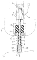
以下、本願発明の好ましい実施の形態を図面を参照しつつ、説明する。図1は一実施形態に係る体液測定装置の全体外観図、図2は挿着体の内部構造の詳細を示す拡大縦断面図、図3は挿着体の横断面図、図4〜図6は本体の内部構造を示すとともに動作を説明するための概略縦断面図である。
【0036】
図1および図2に示されるように、本願発明に係る体液測定装置10は、本体20と挿着体30とを組み合わせて使用される。本体20は、その側面にスイッチボタン類21、LCD表示器22などが配置されている。この本体20の前部には、後に詳細を説明する挿着体30を挿入受容するソケット部23を備える。また、この本体20の内部には、後述する挿着体30に内蔵される可動体を駆動する駆動機構40、および、マイクロコンピュータ等の回路24(図4〜図6)が内蔵される。図1において符号41は、上記駆動機構40の一部を構成し、挿着体30内の可動体31ないしその先端の穿刺体32を後方に引き絞るための摘み部、符号42は引き絞った状態の可動体31ないし穿刺体32を発射するための発射ボタンをそれぞれ示す。
【0037】
図2および図3に示されるように、挿着体30は、筒状外套体35と、この筒状外套体35の内部を軸方向に進退移動可能であり、先端に電極を兼ねた穿刺体32を備えた可動体31とを備える。
【0038】
筒状外套体35は、中心貫通孔34a を有するとともに、基端側大径部34b と先端側小径部34c とを備えた樹脂等の絶縁体34と、この絶縁体34の小径部34c にその根元まで外嵌される円筒状電極36を備える。この円筒状電極36は、その全長が上記絶縁体34の小径部34c の軸方向長さよりも長くなっており、たとえば炭素を主成分とする炭素電極とされる。なお、この電極36としては、白金や金等の貴金属電極、あるいは、炭素と貴金属の複合電極とすることもできる。
【0039】
一方、可動体31は、上記絶縁体34の中心貫通孔34a と対応した外径を有するとともに所定長さをもち、かつ先端を針状の尖端とした穿刺体32と、その基部に一体形成した大径部33とをもった形態を有し、電極を兼用させるために全体がたとえばステンレス鋼によって形成される。この可動体31は、穿刺体32が上記絶縁体34の中心貫通孔34a に通された状態において、筒状外套体35に対し、所定距離軸方向に往復移動可能である。なお、上記絶縁体34の内面には、疎水性処理を施しておくことが、絶縁体34と穿刺体32との間に検体である血液等が侵入することを適切に防止しうるので好都合である。
【0040】
円筒状電極36における上記絶縁体34の小径部34c よりも前方に突出する部分の内面には、適当な反応試薬の層からなる反応層37が形成されている。この体液測定装置10を血糖値を測定するものとして構成する場合、上記反応層37は、酸化酵素であるグルコースオキシターゼ(GOD)およびメディエータとしてのフェリシアン化カリウムやフェロセン等を含むものとして形成される。この反応層37はたとえば、GODおよびフェリシアン化カリウムの混合水溶液中に上記円筒状電極36をディップし、円筒状電極36外面に付着した水溶液を払拭除去した後、乾燥することによって形成することができる。なお、円筒状電極36に対する反応層37の付着性、検体に対する親水性を得るために、上記水溶液のディップ前にあらかじめ電極上に親水性高分子層(たとえばカルボキシメチルセルロース)を形成し、かつ、上記水溶液にも同じ親水性高分子を混合しておくことが望ましい。なお、この円筒状電極36の基端方には、その内部空間と外部とを貫通させる空気抜き孔38が適宜設けられる。後述するように、検体の毛管現象による円筒状電極36内空間への引き込みを促すためである。
【0041】
上記円筒状電極36の寸法、および、穿刺体32の寸法はとくに限定されないが、以下に例示するように、必要検体量を従来に比較して著しく少なくするべく設定することができる。たとえば、穿刺体32の外径を従来のランセット針と同等の0.3mm とすると、上記円筒状電極36の内径は、たとえば、0.6mm 程度、長さをたとえば1mm 程度とすることが、検体を毛管現象によって適正に上記電極36内に引き込む上で望ましいであろう。穿刺体32の外径は、たとえば0.2 〜0.4mm の範囲から選択し、円筒状電極36の内径は0.4 〜1.2mm 、好ましくは0.5 〜0.8mm の範囲から選択することが、穿刺体32および円筒状電極36の作製の容易性、好適な毛管現象の誘起という観点から望ましいであろう。
【0042】
なお、上記した挿着体30は、毎回の適正な測定、衛生面から、使い捨てとして構成し、かつ供給するのが望ましい。
【0043】
図2に示すように、本体20の前部には、上記挿着体30を挿着受容するためのソケット部23が配置されている。このソケット部23は、基本的には、上記挿着体30における筒状外套体35の基部を挿入できるように構成されているとともに、挿着体30が挿入されたとき、筒状外套体35の円筒状電極36の基部に接触する端子25が配置されたものである。
【0044】
図4〜図6に示されるように、本体20内にはまた、上記挿着体30の筒状外套体35がソケット部23に挿入されたとき、挿着体30の可動体31の基部が挿入受容される駆動体43が挿着体30の軸線方向に移動可能に組み込まれている。この駆動体43の後端部には、本体20の後端に突出して臨む摘み部41が連結されている。したがって、この駆動体43は、後端の摘み部41を摘んで後方に引くことができるが、この際、前方に向けた付勢力が蓄勢されるようにコイルバネ44がこの駆動体43に套挿されている。本実施形態の場合、コイルバネ44の両端は、それぞれ、駆動体43および本体側の支持板に連結されており、必ずしも駆動体43を前方に向けて移動させるのみならず、いったん駆動体43が移動行程の前端(すなわち、穿刺体32の先端が挿着体30の先端から所定長さ突出した状態)まで移動した後、所定距離後方へ引き戻して自然状態に戻す役割を果たす。
【0045】
符号26は、本体20に支持されたストッパレバー示し、軸26a を中心として揺動可能であるとともに、先端にストッパ爪26b が、後端に本体20の上部に臨む解除ボタン26c がそれぞれ形成されている。また、図示しないリセットボタンによりこのストッパレバー26は図4に示す矢印a方向に揺動した姿勢をとる。このリセット状態においてこのストッパレバー26は、先端ストッパ爪26b が上記駆動体43の段部43a に係合してこの駆動体43の後方移動を阻止するが、上記解除ボタン26c を押下すると、ストッパ爪26b の段部43a に対する係合が解除されて、駆動体43の後方移動が可能となる。なお、上記ストッパ爪26b は、全体として前方に向かうほど駆動体43に近づくように傾斜して延出しているとともに退避回動可能であるため、後述する駆動体43の前方発射動作を阻害することはない。
【0046】
上記駆動体43の軸方向所定部位には、ラッチレバー43b が形成されている。このラッチレバー43b は、駆動体43が所定量後方に引かれると本体に設けた係合穴27に弾性係入して、駆動体43がバネ44を蓄勢しつつ後方に引かれた状態を保持する。
【0047】
図4〜図6において符号42は、本体20の上部に臨むように配置された発射ボタンを示す。この発射ボタン42を押下すると、上記ラッチレバー43b の上記係合穴27に対する係合を強制解除する。
【0048】
このようにして、これら駆動体43、コイルバネ44、発射ボタン42等が協働して、挿着体30の可動体31ないし穿刺体32を勢いよく前進駆動させるための駆動機構40を構成する。
【0049】
さらに、図4〜図6において符号28は、挿着体30における電極としての穿刺体32ないしは可動体31との導通を図るための端子を示し、穿刺体32ないし可動体31が所定の軸方向移動位置にあるとき、可動体31の一部に導通接触することができるように構成されている。
【0050】
上記ソケット部23において円筒状電極36と導通を図るための端子25、および、対極としての穿刺体32ないし可動体31との導通を図るための端子28は、電子回路24に接続されている。この電子回路24は、マイクロコンピュータなどで構成され、後述するように酵素反応および電気化学反応によって生じる陽極電流から検量線を用いて血糖値等の被検知物質の測定値を決定するとともに、これを本体20の表面に配置した表示器22に表示する機能をもたせてある。
【0051】
次に、上記構成の体液測定装置10の使用方法ないし動作を説明する。
【0052】
図4に示す状態においては、本体20において、駆動体43はその移動行程の前方に位置しており、ストッパレバー26により、後方移動が阻止される状態となっている。この本実施形態においてこの状態を得るには、摘み部41を押して駆動体43をその移動行程の前端に位置させ、図示しないリセットボタンによってストッパレバー26を矢印a方向に揺動させてストッパ爪26bを駆動体43の段部43aに係止させる。この状態において、挿着体30を本体20に挿入すると、筒状外套体35はソケット部23に挿入され、可動体31の基端が駆動体43の前端に受容保持される(図4)。
【0053】
次に、ストッパレバー26の解除ボタン26c を押下して駆動体43の後方移動を可能とし、その後端摘み部41を引っ張ると、バネ44を蓄勢しつつこの駆動体43ないしその先端に接続された可動体31ないし穿刺体32が所定量後退した時点でラッチレバー43b が自動的に係合穴27に係合し、その後退状態が保持される(図5)。
【0054】
挿着体30の先端、すなわち、円筒状電極36の先端を患者の指先等に押し付けながら発射ボタン42を押下すると、ラッチレバー43b の係合が解除され、駆動体43、可動体31ないし穿刺体32がバネ44の弾力によって勢いよく前方に向けて所定距離発射され、穿刺体32の先端が円筒状電極36の先端から適当長さ突出して患者の皮膚に傷をつけ(図2の仮想線)、次の瞬間上記バネ44による引き戻し力によって所定距離引き戻される(図6,図2の実線)。なお、この場合においても、穿刺体32の先端が円筒状電極36内の空間に臨むようにしておくことが肝要である。
【0055】
穿刺体32によってつけられた傷から出液した血液は、毛管現象によって上記円筒状電極36内の空間に引き込まれる。前述したように、上記電極36の反応層37が血液によって溶解されると、数1に示される酵素反応が開始される結果、反応層37に共存させているフェリシアン化カリウムが還元され、還元型の電子伝達体であるフェロシアン化カリウムが蓄積される。その量は、基質濃度、すなわち血液中のグルコース濃度に比例する。一定時間蓄積された還元型の電子伝達体は、数2で示される電気化学反応により、酸化される。測定装置本体20内の電子回路24は、このとき測定される陽極電流から、グルコース濃度(血糖値)を演算・決定し、好ましくはたとえば本体表面に配置されたLCD表示器22に表示する。
【0056】
このように、上記体液測定装置10によれば、本体20に挿着された挿着体30の先端を患者の指先等に押し当てた状態を保持しつつ、あたかも従来のランセットを扱うようにして穿刺体32を突出させるという操作をするだけで、それ以上の操作、あるいは動作を要することなく、血糖値等の体液測定を適正に行うことができる。この体液測定装置10の使用において求められる操作は、ランセットを操作して皮膚に傷をつけ、出液した血液を測定装置の試験片に触れさせるという操作を必要とした従来の測定方法に比較して著しく簡略化されたものとなる。
【0057】
また、上記電極36が円筒状であるとともに、その内部に対極である穿刺体32が配されているという電極構造を採用していることから、測定に要する体液量を著しく少なくすることができ、測定の確実性の著しい向上につながるとともに低侵襲性に寄与することとなる。
【0058】
次に、上記実施形態と同様の挿着体を用いて測定実験を行った結果を図7および図8に示す。なお、実験用として使用した筒状外套体は、外径2mm 、内径0.8mm 、軸方向長さ7mm 、そして先端から軸方向に沿って2.5mm の箇所に空気抜き孔を設けたものである。また、可動体における穿刺体は、外径0.36mm、長さ5.5mm (実質有効長さ3mm )、そして基端側から2mm の長さにわたり外径0.8mm のチューブによって被覆したものを用いた。したがって、円筒状の電極内空間は、その内径が0.8mm 、最低でも長さが2.5mm として1.2566μlの容積を確保している。
【0059】
また、筒状外套体は、蒸留水中で超音波洗浄した後、カルボキシメチルセルロース(CMC)0.25重量%とイソプロピルアルコール20重量%との混合水溶液 2μlにディップされ、さらに50℃15分程度の乾燥を経ることで反応層1層目に親水性高分子層を有したものである。さらに、筒状外套体は、GOD 333U/ml(U:酵素やホルモン等の効力を国際的に統一して示すための実用単位)とフェリシアン化カリウム26.7mg/mlとの混合水溶液 2.5μlにディップされ、同じく50℃10分程度の乾燥を経ることにより2層目とした反応層を有している。
【0060】
このような筒状外套体に対してチューブで絶縁被覆された穿刺体を差し込んだ状態として実験を行った。測定用サンプルとしては、 100,200,500mg/dlの各グルコースを含む 0.9重量%のNaCl水溶液を使用し、この水溶液を筒状外套体の電極内空間に毛管現象によって引き込ませた。測定方法としては、電極内空間にNaCl水溶液を引き込んだ状態で15秒放置した後、サイクリックボルタンメトリが適用され、測定条件として掃引速度を100mV/sec、掃引範囲を0〜1000mVとして図7に示す測定結果を得た。
【0061】
図7に示す測定結果から 800mVにおけるデータを抽出し、回帰分析を行った結果、図8に示すような相関関係を示す直線式を得た。なお、グラフに示す直線式は、最小二乗法によりR−2乗値を算出して線形近似されたものである。このグラフに示すように、電流値は、グルコース濃度に応じて線形的に増加する傾向にあり、グルコース濃度に比例して一定した割合(0.0567)で測定されることが読みとれる。したがって、本実施形態に係る体液測定装置によれば、実際の使用時においても、血液中のグルコース濃度(血糖値)を精度良く測定することが理解できよう。
【0062】
さらに他の実施形態として、上記実施形態とは挿着体が若干異なるものを図9に示し、これについて説明する。なお、上記実施形態と同様の構成部材については、同一符号を付して動作説明などを省略する。図9に示す挿着体50は、筒状外套体55と、この筒状外套体55の内部を軸方向に進退移動可能であり、細管部52a と軸芯部52b とにより一対の電極として兼用される穿刺体52を備えた可動体51とを備える。
【0063】
筒状外套体55は、中心貫通孔54a を有するとともに、基端側大径部54b と先端側小径部54c とを備えたかたちで樹脂等の絶縁材により構成されている。この筒状外套体55の先端には、上述の実施形態と同様に空気抜き孔58を通じて外部に通じる内部空間が設けられている。
【0064】
一方、可動体51は、上記筒状外套体55の中心貫通孔54a と対応した外径を有するとともに所定長さをもち、かつ先端を針状の尖端とした穿刺体52と、その基部に一体形成した大径部53とをもった形態を有している。穿刺体52の部分では、一対の電極を兼用させるために断面構造上、細管部52a と軸芯部52b とが絶縁性材料52c によって絶縁されている。絶縁性材料52c は、たとえばシリコーン樹脂、エポキシ樹脂、あるいはフッ素系樹脂などが用いられる。穿刺体52の尖端内部には、適当な反応試薬の層からなる反応層57を底にして微小空間52d が形成されている。また、大径部53においては、細管部52a および軸芯部52bのそれぞれに連続して電気的に導通可能な2つの部分53a ,53b が絶縁層52c を介して分けられている。この可動体51は、穿刺体52が上記外套体55の中心貫通孔54a に通された状態において、その外套体55に対して所定距離軸方向に往復移動可能である。このような穿刺体52の細管部52a は対極として機能するとともに、他方の軸芯部52b は作用電極として機能する。
【0065】
このような可動体51を製作する際、穿刺体52の細管部52a としては、外径0.3mm 、内径0.18mm程度(ゲージ番号30)の中空針状部分、あるいは外径0.26mm、内径0.13mm程度(ゲージ番号31)の中空針状部分を有するステンレスや白金などでできた中空針が用いられる。一方、ゲージ番号30に相当する穿刺体52の細管部52a を採用する場合、穿刺体52の軸芯部52b としては、たとえば最細部が0.15mmの外径を有し、カーボンファイバー、グラッシーカーボン、グラファイト、白金、パラジウムあるいは金などの非腐食性の金属でできた一部極細のワイヤを用いる。このワイヤは、撥水性の高い絶縁性のポリテトラフルオロエチレン樹脂などが被覆形成されることにより、その外径が上記細管部52a の内径に応じた0.18mm程度とされる。なお、中空針やワイヤは、それらの基端側に符号53a ,53b で示す大径部53の一部を有している。そして、ワイヤの先端を切断した後、その先端面には、上述の実施形態と同様にして反応層57が形成され、十分に乾燥を経た後、ワイヤは、上記中空針の尖端に微小空間52d を残すように挿入されることで中空針と一体化され、これにより、穿刺体52を備えた可動体51が完成する。なお、ポリテトラフルオロエチレン樹脂は、上記穿刺体52における絶縁層52c に相当する。また、穿刺体52の尖端には、皮膚を穿刺する際の刺撃を和らげて無痛感を生むべく、シリコーンなどを含む軟膏剤を塗着しておいてもよい。
【0066】
上記筒状外套体55の寸法、および、穿刺体52の寸法はとくに限定されないが、以下に例示するように、必要検体量を従来に比較して著しく少なくするべく設定することができる。たとえば、穿刺体52の尖端を適当な寸法分斜めにカットした形状とし、その尖端内部における微小空間52d の内径を0.18mmとすると、この微小空間52d 内においては、細管部52a と軸芯部52b の先端の反応層57に接触するだけの血液が採取できればよいこととなる。したがって、筒状外套体55の内部全体に血液が充填される必要はなく、上述の実施形態に比べても採取血液量がいかに少量ですむか理解できよう。
【0067】
なお、先の実施形態と同様に、上記した挿着体50は、毎回の適正な測定、衛生面から、使い捨てとして構成し、かつ供給するのが望ましい。
【0068】
また、図9において符号28a は、挿着体50において対極として機能する穿刺体52の細管部52a に対して導通を図るための端子を示し、一方、符号28b は、作用電極として機能する穿刺体52の軸芯部52b に対して導通を図るための端子を示す。つまり、穿刺体52ないし可動体51が所定の軸方向移動位置にあるとき、可動体51の符号53a ,53b で示す部分に各端子28a ,28b が接触し、上記実施形態と同様に図示しない電子回路によって血糖値等の被検知物質の測定値が算出されるのである。
【0069】
したがって、上記構成を有する他の実施形態に係る体液測定装置によれば、必要とされる検体量は、極めて細い穿刺体52の尖端における微小空間52d を満たすだけのわずかな容積でよく、先の実施形態と比較しても明らかなように、さらに微量の検体量でも測定可能である。要するに、穿刺体52の尖端によって皮膚を突き刺す深さは、従来の装置はもとより先の実施形態に比べても小さくてすみ、このことから図9に示す体液測定装置は、低侵襲性に優れたものと言えよう。
【0070】
もちろん、この発明の範囲は上述した各実施形態に限定されることはない。各実施形態では、血糖値を測定するためのものとして説明されているが、測定対象は血糖値に限定されない。また、各実施形態では、筒状外套体および筒状外套体が有する電極を円筒状としているが、円筒状であること必須ではなく、穿刺体を取り囲む形態であれば、他の筒状形態であればよい。
【図面の簡単な説明】
【図1】
本願発明に係る体液測定装置の本体の全体斜視図である。
【図2】
挿着体の詳細を示す拡大縦断面図である。
【図3】
図2のIII-III 線に沿う拡大断面図である。
【図4】
本体の内部構造を示すとともに作用を説明するための概略断面図である。
【図5】
本体の内部構造を示すとともに作用を説明するための概略断面図である。
【図6】
本体の内部構造を示すとともに作用を説明するための概略断面図である。
【図7】
挿着体を用いて測定実験を行った結果を説明するために示した図である。
【図8】
図7に示す測定結果に基づいて回帰分析を行った結果を説明するために示した図である。
【図9】
本願発明の他の実施形態にかかる挿着体の詳細を示す拡大縦断面図である。
【符号の説明】
10 体液測定装置
20 本体
22 表示器
23 ソケット部
24 電子回路
25 端子
30 挿着体
31 可動体
32 穿刺体
34 絶縁体
35 筒状外套体
36 円筒状電極
37 反応層
40 駆動機構
41 摘み部
42 発射ボタン
43 駆動体
44 バネ
50 挿着体
51 可動体
52 穿刺体
52a 細管部
52b 軸芯部
52c 絶縁層
55 筒状外套体
57 反応層
[Document name] Specification [Title of invention] Body fluid measuring device and insert body used by inserting into the body fluid measuring device [Claims]
1. A body fluid measuring device including a main body and an insert body to be inserted and used in the main body.
The insert has an electrode having an open tip and an inner surface to which a predetermined reaction reagent is attached, and has a tubular mantle inserted into the main body at the base and an axis around the inside of the tubular mantle. It is equipped with a movable body that can move forward and backward in the direction and has a puncture body that is also used as an electrode at the tip.
The main body has a terminal that conducts with each electrode included in the insert when the insert is inserted, an electronic circuit that determines a measured value based on an electric signal obtained through the terminal, and an electronic circuit. A body fluid measuring device comprising a driving mechanism for driving the movable body forward to cause the puncture body at the tip thereof to protrude from the tip of the tubular mantle.
2. The body fluid measuring device according to claim 1, wherein the electrode of the tubular mantle in the insert and the puncture body at the tip of the movable body are arranged concentrically.
3. The body fluid measuring apparatus according to claim 1, wherein the inner diameter of the electrode of the tubular mantle in the insert is 0.4 to 1.2 mm, preferably 0.5 to 0.8 mm.
4. The body fluid measuring device according to claim 3, wherein the puncture body in the insert body is a needle having a tip, and the outer diameter thereof is 0.2 to 0.4 mm.
5. A body fluid measuring device including a main body and an insert body to be inserted and used in the main body.
The insert has a tubular mantle that is inserted into the main body at the base while the tip is opened, and the inside of the tubular mantle can be moved forward and backward in the axial direction, while a predetermined reaction reagent is provided at the tip. It is provided with a movable body having a puncture body at the tip, which is attached to the tube and is insulated from each other in terms of cross-sectional structure, and the shaft core portion is also used as a pair of electrodes.
The main body has a terminal that conducts with each electrode included in the insert when the insert is inserted, an electronic circuit that determines a measured value based on an electric signal obtained through the terminal, and an electronic circuit. A body fluid measuring device comprising a driving mechanism for driving the movable body forward to cause the puncture body at the tip thereof to protrude from the tip of the tubular mantle.
6. The capillary portion as an electrode of the puncture body in the insert body has a hollow tip that is longer on the tip side than the shaft core portion, and the shaft core portion inside the tip has a hollow tip. The body fluid measuring apparatus according to claim 5, wherein a predetermined reaction reagent is attached to the tip.
7. The inner diameter of the thin tube portion as an electrode of the puncture body in the insert body is such that the inner diameter can be inserted while insulating the axial core portion, preferably about 0.13 to 0.18 mm. The body fluid measuring device according to claim 5 or 6.
8. The body fluid measuring device according to claim 7, wherein the puncture body in the insert body has an outer diameter of 0.2 to 0.4 mm.
9. The axial core portion of the insert body as the electrode of the tubular mantle or the electrode of the puncture body is formed of carbon, a noble metal, or a composite thereof. The body fluid measuring device according to any one of 1 to 8.
10. An inserter to be used by being attached to the main body of the body fluid measuring device according to any one of claims 1 to 9.
11. The insert according to claim 10, wherein the tubular mantle has an insulator interposed between the electrode provided therein and the puncture body provided by the movable body. , This insulator is an inserter used by being inserted into a body fluid measuring device, characterized in that the surface facing the puncture body is subjected to a hydrophobic treatment.
12. The puncture body according to claim 10, wherein the puncture body has an obliquely cut cut-shaped apex and is entirely hollow needle-shaped, and the thin tube portion. It has a structure in which the shaft core portion inserted inside via an insulating layer is combined as a pair of electrodes, and the inside of the tip of the thin tube portion is the shaft core portion to which a predetermined reaction reagent is adhered. An insert body used by being inserted into a body fluid measuring device, characterized in that a very small space is provided so that the tip faces.
13. A tubular mantle having an electrode having an open tip and an inner surface to which a predetermined reaction reagent is attached, and being inserted into a body fluid measuring device main body at a base, and the inside of the tubular mantle. An insertable body that can be moved forward and backward in the axial direction and is provided with a movable body having a puncture body that is also used as an electrode at the tip, and is used by being inserted into a body fluid measuring device.
14. A tubular mantle inserted into the body fluid measuring device main body at the base while the tip is opened, and a predetermined reaction to the tip while being able to move forward and backward in the axial direction inside the tubular mantle. A body fluid measuring apparatus comprising a movable body having a puncture body at the tip, which has a capillary portion and a shaft core portion which are insulated from each other in terms of cross-sectional structure as a pair of electrodes and to which a reagent is attached. An insert body to be used by attaching to.
Description: TECHNICAL FIELD [Detailed description of the invention]
[0001]
[Technical field to which the invention belongs]
The present invention relates to a body fluid measuring device capable of measuring a substance to be detected contained in a body fluid such as a blood glucose concentration (hereinafter referred to as "blood glucose level").
0002.
[Conventional technology]
In the treatment of diabetes, it is necessary to keep the blood glucose level of the patient within the normal range, and the blood glucose level management by the patient himself is an important treatment method. In particular, in the treatment of insulin-dependent diabetes mellitus, the blood glucose level is maintained in the normal range by insulin injection by the patient himself, and for that purpose, appropriate blood glucose level measurement by the patient himself is indispensable.
0003
A portable blood glucose measuring device used for such a purpose is already on the market, and an example thereof is shown in, for example, Japanese Patent Publication No. 8-20412. This blood glucose level measuring device is used by inserting a disposable test piece having an enzyme electrode into the main body. When the test piece is brought into contact with the sample blood, a part of the blood is drawn into the reaction part by a capillary phenomenon, and an anodic current is generated through an enzymatic reaction and an electrochemical reaction. This anode current is converted into a blood glucose level in the main body of the apparatus and displayed.
0004
By the way, the sample to be brought into contact with the test piece of the measuring device as described above, that is, blood is generally collected by using an instrument called a lancet, for example, as shown in Japanese Patent Application Laid-Open No. 9-266898. Is. This lancet is a device for making (damaging) a small hole in the skin such as the fingertip of a patient, and the blood discharged from the hole made in this way is brought into contact with a predetermined part of the above-mentioned test piece. Therefore, the self-measurement of the blood glucose level can be performed relatively easily.
0005
[Problems to be Solved by the Invention]
However, in the conventional general self-monitoring method of blood glucose level described above, since the lancet for collecting blood as a sample and the measuring device are separate bodies, the lancet is combined with the inconvenience of having to carry both of them. It is necessary to perform two actions, one is to damage the skin and the other is to touch the blood discharged from the wound with the test piece, and there is still room for improvement in usability. In particular, regarding the action of touching the test piece with blood, it is necessary to bring the required amount of blood into contact with the specified part of the test piece, and such an action is quickly and appropriately performed for an inexperienced patient or a patient with poor eyesight. It is difficult to do.
0006
Further, since the test piece is configured to draw blood from the hole at the tip to the surface enzyme electrode provided in the reaction part by a capillary phenomenon, it is necessary to bring the required amount of blood to the reaction part from 3 to 3. It is necessary to bring 5 μl of blood into contact with the test piece. If this amount of blood is insufficient, or if this amount of blood is not properly adhered to a small area surrounding the tip hole of the test piece, accurate measurement may not be possible. This situation can occur frequently, especially when the amount of blood discharged from the wound is insufficient, such as in infants and the elderly.
0007
On the other hand, as shown in Japanese Patent Application Laid-Open No. 9-88885, an analyzer equipped with a puncture needle and an electrode and having both blood collection and measurement functions has been proposed, but this device causes pain during blood collection. No measures have been taken regarding the so-called minimally invasiveness such as low invasiveness. In order to achieve this minimal invasiveness, the amount of collected blood may be extremely small, that is, the smaller the amount of collected blood, the smaller the puncture depth by the puncture needle, and it is considered that the invasiveness is further reduced. Those capable of such minimal invasiveness include the devices shown in Japanese Patent Application Laid-Open No. 9-94231 or Japanese Patent No. 2616331.
0008
However, the device according to JP-A-9-94231 is not intended to be disposable, but is used by connecting a skin-insertion type blood collection unit to a measuring device with a cord or the like. In addition, the device according to Japanese Patent No. 2616331 is not a disposable type, but is a device that focuses exclusively on the material of the enzyme electrode to pursue the reduction of blood sampling, and when it is used repeatedly, there is a problem in terms of hygiene management and usability. There is. In short, even with the various devices shown in the conventional publications, it was not possible to achieve both usability, accurate measurement, and minimal invasiveness.
0009
The present invention has been conceived under such circumstances, and it is possible to improve usability by simplifying the operation required for the patient for measurement and significantly reduce the required sample amount. The challenge is to provide a body fluid measuring device that can improve the reliability of measurement and thereby reduce invasiveness.
0010
[Disclosure of Invention]
In order to solve the above problems, the present invention takes the following technical measures.
0011
The body fluid measuring device provided by the first aspect of the present invention is a body fluid measuring device including a main body and an insert body to be inserted and used in the main body.
The insert has an electrode having an open tip and an inner surface to which a predetermined reaction reagent is attached, and has a tubular mantle inserted into the main body at the base and an axis around the inside of the tubular mantle. It is equipped with a movable body that can move forward and backward in the direction and has a puncture body that is also used as an electrode at the tip.
The main body has a terminal that conducts with each electrode included in the insert when the insert is inserted, an electronic circuit that determines a measured value based on an electric signal obtained through the terminal, and an electronic circuit. It is characterized in that it is provided with a driving mechanism for driving the movable body forward and projecting the puncture body at the tip thereof from the tip of the tubular mantle.
0012
In a preferred embodiment, the electrode of the tubular mantle in the insert and the puncture body at the tip of the movable body are concentrically arranged, and the cylindrical electrode is carbon. It can be an electrode made of a noble metal or a composite thereof.
0013
In a preferred embodiment, the inner diameter of the electrode in the insert is set to 0.4 to 1.2 mm, preferably 0.5 to 0.8 mm.
0014.
In a preferred embodiment, the puncture body in the insert is a needle with a tip, the outer diameter of which is 0.2 to 0.4 mm.
0015.
Further, the body fluid measuring device provided by the second aspect of the present invention is a body fluid measuring device including a main body and an insert body to be inserted and used in the main body.
The insert has a tubular mantle that is inserted into the main body at the base while the tip is opened, and the inside of the tubular mantle can be moved forward and backward in the axial direction, while a predetermined reaction reagent is provided at the tip. It is provided with a movable body having a puncture body at the tip, which is attached to the tube and is insulated from each other in terms of cross-sectional structure, and the shaft core portion is also used as a pair of electrodes.
The main body has a terminal that conducts with each electrode included in the insert when the insert is inserted, an electronic circuit that determines a measured value based on an electric signal obtained through the terminal, and an electronic circuit. It is characterized in that it is provided with a driving mechanism for driving the movable body forward and projecting the puncture body at the tip thereof from the tip of the tubular mantle.
0016.
In a preferred embodiment, the capillary portion as an electrode of the puncture body in the insert has a hollow tip that is longer on the tip side than the shaft core portion, and the shaft core inside the tip has a hollow tip. A predetermined reaction reagent is attached to the tip of the portion, and the shaft core portion as the electrode can be an electrode made of carbon, a noble metal, or a composite thereof.
[0017]
In a preferred embodiment, the inner diameter of the thin tube portion as an electrode of the puncture body is set to a dimension that can be inserted while insulating the shaft core portion, preferably about 0.13 to 0.18 mm. To.
0018
Further, in a preferred embodiment, the puncture body has an outer diameter of 0.2 to 0.4 mm.
0019
The insert body used by being inserted into the body fluid measuring device provided by the third aspect of the present invention is provided with an electrode having an open tip and an inner surface to which a predetermined reaction reagent is attached, and a body fluid at the base. It is characterized by including a tubular mantle inserted into the main body of the measuring device and a movable body having a puncture body at the tip, which can move forward and backward in the axial direction inside the tubular mantle. It is said.
0020
In a preferred embodiment, the tubular mantle comprises an insulator interposed between the electrode provided therein and the puncture body provided by the movable body, and the insulator faces the puncture body. The surface to be treated is hydrophobically treated.
0021.
Further, the insert body used by being inserted into the body fluid measuring device provided by the fourth aspect of the present invention includes a tubular mandrel whose tip is opened and inserted into the body fluid measuring device main body at the base portion thereof. While it is possible to move forward and backward in the axial direction inside the tubular mantle, a thin tube portion and a shaft core portion that have a predetermined reaction reagent attached to the tip and are insulated from each other in terms of cross-sectional structure are also used as a pair of electrodes. It is characterized by having a movable body having a puncture body at the tip.
0022.
In a preferred embodiment, the puncture body is interpolated into the tubule portion having an obliquely cut cut-shaped tip and having a hollow needle shape as a whole, and inside the tubule portion via an insulating layer. It has a structure in which the shaft core portion is combined as a pair of electrodes, and a minimum space is provided inside the tip of the thin tube portion so that the tip of the shaft core portion to which a predetermined reaction reagent is attached faces. There is.
[0023]
In the body fluid measuring device according to the first side surface and the insert body according to the third side surface, the tip of the insert body, that is, the tip of the tubular mantle is the patient's own in the state where the insert body is inserted into the main body. When the movable body is driven forward by pressing it against a fingertip or the like and operating the drive mechanism of the main body, the puncture body at the tip of the movable body protrudes from the tip of the tubular mantle and damages the skin such as the patient's fingertip. .. Preferably, the movable body retracts by a predetermined amount, but at least the tip of the puncture body faces the inside of the electrode. When the tip of the tubular mantle is held against the fingertip for a while, the blood discharged from the wound is drawn into the space inside the electrode by capillarity. In this state, blood comes into contact with both the cylindrical inner surface electrode (working electrode) and the puncture body that also serves as the electrode (counter electrode).
0024
The reaction reagent to be deposited on the inner surface of the electrode in order was the blood glucose measurement, those containing potassium ferricyanide as glucose oxidase and the mediator is oxidized enzyme is employed, which forms the reaction layer on the inner surface of the electrode ..
0025
When the reaction layer is dissolved by blood, the enzymatic reaction shown in Equation 1 is started, and as a result, potassium ferricyanide coexisting in the reaction layer is reduced, and potassium ferrocyanide, which is a reduced electron carrier, is accumulated. .. The amount is proportional to the substrate concentration, that is, the glucose concentration in the blood. The reduced electron carrier accumulated for a certain period of time is oxidized by the electrochemical reaction shown in Equation 2. The circuit in the main body of the measuring device calculates and determines the glucose concentration (blood glucose level) from the anodic current measured at this time, and preferably displays it on an LCD display arranged on the surface of the main body, for example.
0026
[Number 1]
[0027]
[Number 2]
[0028]
At this time, as in the preferred embodiment, the surface of the tubular mantle body facing the puncture body of the insulator for insulating the electrode and the puncture body is subjected to a hydrophobic treatment so that blood can be removed. It is possible to appropriately prevent the movable body from penetrating in the axial direction.
[0029]
As described above, according to the body fluid measuring device and the insert body according to the first and third side surfaces, the state in which the tip of the insert body inserted into the main body is pressed against the fingertip of the patient or the like is maintained. By simply performing the operation of projecting the puncture body as if handling a conventional lancet, it is possible to properly measure the body fluid such as the blood glucose level without requiring any further operation or operation. The operation required in the use of the body fluid measuring device according to the present invention is a conventional measuring method that requires an operation of operating a lancet to damage the skin and bringing the discharged blood into contact with a test piece of the measuring device. It is significantly simplified in comparison.
[0030]
Further, when the electrode has a cylindrical shape, the amount of body fluid required for measurement can be significantly reduced because the electrode structure is adopted in which a puncture body, which is a counter electrode, is arranged inside the electrode. For example, if the inner diameter of the cylindrical electrode is 0.6 mm and the axial length is 1 mm, the electrode area is 1.884 mm 2, which is comparable to the electrode area (for example, 1 mm 2) of the conventional test piece. The volume of the cylindrical electrode space is 0.2826 μl. In practice, a part of the puncture body as a counter electrode faces the space inside the cylindrical electrode, and if that portion is subtracted, the internal volume of the cylindrical electrode is further reduced. Moreover, the distance until the blood discharged from the skin reaches the space inside the cylindrical electrode is extremely short. This means that the amount of sample required in the body fluid measuring apparatus according to the present invention may be a small amount corresponding to the extremely small space volume in the electrode as described above. For example, how small the amount of sample required for the electrode structure illustrated above is compared with the amount of sample required for the test piece structure of the measuring device introduced in the prior art, which is 3 to 5 μl. Will be understood. This also contributes to a significant improvement in measurement certainty and minimal invasiveness.
0031
On the other hand, the body fluid measuring device according to the second side surface and the insert body according to the fourth side surface also have mechanical, chemical and electrical actions in almost the same manner as those according to the first and third side surfaces. However, the blood discharged from the wound is drawn into the tip of the capillary portion of the puncture body by the capillary phenomenon. In this state, blood comes into contact with both the axial core portion configured as an electrode (working electrode) inside the tip of the puncture body and the capillary portion also configured as an electrode (counter electrode), so that the tip of the axial core portion is contacted. The anodic current is measured through the reaction layer in.
[0032]
At this time, as in the preferred embodiment, an extremely small space is provided inside the tip of the capillary portion of the puncture body so that the tip of the shaft core portion to which the reaction reagent is attached faces, so that the puncture body has penetrated into the extremely small space. The blood is surely in contact with both the shaft core portion as the electrode and the capillary portion, and a sufficient current flows for the measurement.
0033
Therefore, according to the body fluid measuring device and the insert according to the second and fourth side surfaces, the same effect as that of the first and third side surfaces can be obtained. Moreover, since it is only necessary to collect a small amount of blood that fills the extremely small space at the tip of the extremely thin puncture body, the depth at which the skin is pierced by the tip of the puncture body is compared with the case of the first and third aspects. But you can see that it can be made significantly smaller. And this, together with the leads to improved reliability of the measurement, and thus lead to improved have authored very collected blood volume traces were prerequisite minimally invasive.
0034
Other features and advantages of the present invention will become apparent from the detailed description given below with reference to the drawings.
0035.
BEST MODE FOR CARRYING OUT THE INVENTION
Hereinafter, preferred embodiments of the present invention will be described with reference to the drawings. 1 is an overall external view of the body fluid measuring device according to the embodiment, FIG. 2 is an enlarged vertical sectional view showing details of the internal structure of the insert, FIG. 3 is a cross-sectional view of the insert, and FIGS. 4 to 6 are shown. Is a schematic vertical sectional view for showing the internal structure of the main body and explaining the operation.
0036
As shown in FIGS. 1 and 2, the body fluid measuring device 10 according to the present invention is used in combination with the main body 20 and the insert body 30. The main body 20 has switch buttons 21, an LCD display 22, and the like arranged on its side surface. This is preceded portion of the main body 20 includes a socket 23 for inserting receiving insertion member 30 to be described in detail later. Further, inside the main body 20 , a drive mechanism 40 for driving a movable body built in the insertion body 30 described later, and a circuit 24 (FIGS. 4 to 6) of a microcomputer or the like are built in. In FIG. 1, reference numeral 41 constitutes a part of the drive mechanism 40, and reference numeral 42 is a knob portion for narrowing the movable body 31 in the insert body 30 or the puncture body 32 at the tip thereof rearward. The firing buttons for firing the movable body 31 or the puncture body 32 in the state are shown respectively.
0037
As shown in FIGS. 2 and 3, the insert body 30 can move forward and backward in the axial direction of the tubular mantle 35 and the inside of the tubular mantle 35, and is a puncture body having an electrode at the tip. It is equipped with a movable body 31 having 32.
[0038]
The tubular mantle 35 has a central through hole 34a, an insulator 34 such as a resin having a large diameter portion 34b on the proximal end side and a small diameter portion 34c on the distal end side, and a small diameter portion 34c of the insulator 34. A cylindrical electrode 36 that is externally fitted to the root is provided. The total length of the cylindrical electrode 36 is longer than the axial length of the small diameter portion 34c of the insulator 34, and the cylindrical electrode 36 is, for example, a carbon electrode containing carbon as a main component. The electrode 36 may be a noble metal electrode such as platinum or gold, or a composite electrode of carbon and noble metal.
[0039]
On the other hand, the movable body 31 is integrally formed with the puncture body 32 having an outer diameter corresponding to the central through hole 34a of the insulator 34, having a predetermined length, and having a needle-shaped tip at the tip thereof, and the base thereof. It has a form having a large diameter portion 33, and is entirely made of, for example, stainless steel so that it can also serve as an electrode. The movable body 31 can reciprocate with respect to the tubular mantle 35 in a predetermined distance axial direction in a state where the puncture body 32 is passed through the central through hole 34a of the insulator 34. It is convenient to apply a hydrophobic treatment to the inner surface of the insulator 34 because blood or the like as a sample can be appropriately prevented from entering between the insulator 34 and the puncture body 32. is there.
0040
A reaction layer 37 made of a layer of an appropriate reaction reagent is formed on the inner surface of the portion of the cylindrical electrode 36 that protrudes forward from the small diameter portion 34c of the insulator 34. When the body fluid measuring device 10 is configured to measure the blood glucose level, the reaction layer 37 is formed to contain glucose oxidase (GOD) which is an oxidase and potassium ferricyanide or ferrocene as a mediator. The reaction layer 37, for example, the cylindrical electrodes 36 by dipping in an aqueous solution of GOD and potassium ferricyanide, after wiping remove solution adhering to the cylindrical electrode 36 outer surface may be formed by drying .. In order to obtain the adhesion of the reaction layer 37 to the cylindrical electrode 36 and the hydrophilicity to the sample, a hydrophilic polymer layer (for example, carboxymethyl cellulose) is formed on the electrode in advance before dipping the aqueous solution, and the above. It is desirable to mix the same hydrophilic polymer with the aqueous solution. Incidentally, the base end side of the circular cylindrical electrode 36, an air vent hole 38 to penetrate the inner space and the outside is provided as appropriate. As will be described later, this is to promote the drawing of the sample into the inner space of the cylindrical electrode 36 due to the capillary phenomenon.
[0041]
The dimensions of the circular cylindrical electrode 36, and is not particularly limited dimensions of the puncture body 32, as illustrated below, it can be set to be significantly less compared to required sample volume to the prior art. For example, assuming that the outer diameter of the puncture body 32 is 0.3 mm, which is equivalent to that of a conventional lancet needle, the inner diameter of the cylindrical electrode 36 is, for example, about 0.6 mm, and the length is, for example, about 1 mm. It would be desirable to properly draw it into the electrode 36 depending on the phenomenon. The outer diameter of the puncture body 32 can be selected from the range of 0.2 to 0.4 mm, for example, and the inner diameter of the cylindrical electrode 36 can be selected from the range of 0.4 to 1.2 mm, preferably 0.5 to 0.8 mm. It would be desirable from the viewpoint of ease of fabrication of the shape electrode 36 and induction of a suitable capillary phenomenon.
[0042]
It is desirable that the above-mentioned insert 30 is configured and supplied as a disposable body from the viewpoint of proper measurement and hygiene each time.
[0043]
As shown in FIG. 2, a socket portion 23 for inserting and receiving the insertion body 30 is arranged on the front portion of the main body 20. The socket portion 23 is basically configured so that the base portion of the tubular mantle 35 in the insert 30 can be inserted, and when the insert 30 is inserted, the tubular mantle 35 is inserted. The terminal 25 that comes into contact with the base of the cylindrical electrode 36 of the above is arranged.
[0044]
As shown in FIGS. 4 to 6, when the tubular mantle 35 of the insert body 30 is inserted into the socket portion 23, the base of the movable body 31 of the insert body 30 is also contained in the main body 20. The drive body 43 to be inserted and received is incorporated so as to be movable in the axial direction of the insert body 30. A knob 41 that projects to the rear end of the main body 20 is connected to the rear end of the drive body 43. Therefore, the drive body 43 can be pulled backward by picking the knob portion 41 at the rear end, but at this time, the coil spring 44 is attached to the drive body 43 so that the urging force toward the front is accumulated. It is inserted. In the case of the present embodiment, both ends of the coil spring 44 are connected to the drive body 43 and the support plate on the main body side, respectively, and not only the drive body 43 is necessarily moved forward, but also the drive body 43 is once moved. After moving to the front end of the stroke (that is, the tip of the puncture body 32 protrudes by a predetermined length from the tip of the insert body 30), it plays a role of pulling back a predetermined distance to return to the natural state.
0045
Reference numeral 26 indicates a stopper lever supported by the main body 20, which can swing around the shaft 26a, and has a stopper claw 26b formed at the tip and a release button 26c facing the upper part of the main body 20 at the rear end. There is. Further, the stopper lever 26 takes a posture of swinging in the direction of arrow a shown in FIG. 4 by a reset button (not shown). In this reset state, the tip stopper claw 26b engages with the step portion 43a of the drive body 43 to prevent the drive body 43 from moving backward, but when the release button 26c is pressed, the stopper claw 26 The engagement of 26b with the step 43a is disengaged, and the drive body 43 can be moved backward. It should be noted that the stopper claw 26b is inclined and extended so as to approach the driving body 43 toward the front as a whole, and can be retracted and rotated, so that the forward firing operation of the driving body 43, which will be described later, is hindered. There is no.
[0046]
A latch lever 43b is formed at a predetermined portion in the axial direction of the drive body 43. When the drive body 43 is pulled backward by a predetermined amount, the latch lever 43b elastically engages with the engagement hole 27 provided in the main body, and the drive body 43 is pulled backward while accumulating the spring 44. Hold.
[0047]
In FIGS. 4 to 6, reference numeral 42 indicates a firing button arranged so as to face the upper part of the main body 20. When the firing button 42 is pressed, the engagement of the latch lever 43b with the engagement hole 27 is forcibly released.
0048
In this way, the drive body 43, the coil spring 44, the firing button 42, and the like cooperate to form a drive mechanism 40 for vigorously driving the movable body 31 or the puncture body 32 of the insert body 30 forward.
[0049]
Further, in FIGS. 4 to 6, reference numeral 28 indicates a terminal for conducting conduction with the puncture body 32 or the movable body 31 as an electrode in the insert body 30, and the puncture body 32 to the movable body 31 is in a predetermined axial direction. It is configured so that it can make conductive contact with a part of the movable body 31 when it is in the moving position.
0050
In the socket portion 23, the terminal 25 for conducting conduction with the cylindrical electrode 36 and the terminal 28 for conducting conduction with the puncture body 32 or the movable body 31 as counter electrodes are connected to the electronic circuit 24. This electronic circuit 24 is composed of a microcomputer or the like, and as will be described later, determines the measured value of the substance to be detected such as the blood glucose level from the anodic current generated by the enzymatic reaction and the electrochemical reaction using a calibration curve, and determines the measured value of the substance to be detected. It has a function to display on the display 22 arranged on the surface of the main body 20.
0051
Next, the usage method or operation of the body fluid measuring device 10 having the above configuration will be described.
[0052]
In the state shown in FIG. 4, in the main body 20, the drive body 43 is located in front of the movement stroke, and the stopper lever 26 prevents the rear movement. In this embodiment, in order to obtain this state, the knob portion 41 is pushed to position the drive body 43 at the front end of the movement stroke, and the stopper lever 26 is swung in the direction of arrow a by a reset button (not shown) to cause the stopper claw 26b. Is locked to the step portion 43a of the drive body 43. In this state, when the insert body 30 is inserted into the main body 20, the tubular mantle 35 is inserted into the socket portion 23, and the base end of the movable body 31 is received and held by the front end of the drive body 43 (FIG. 4).
[0053]
Next, the release button 26c of the stopper lever 26 is pressed to enable the drive body 43 to move backward, and when the rear end knob 41 is pulled, the spring 44 is connected to the drive body 43 or its tip while accumulating energy. When the movable body 31 or the puncture body 32 retracts by a predetermined amount, the latch lever 43b automatically engages with the engaging hole 27, and the retracted state is maintained (FIG. 5).
0054
When the firing button 42 is pressed while pressing the tip of the insert body 30, that is, the tip of the cylindrical electrode 36, against the patient's fingertip or the like, the latch lever 43b is disengaged, and the drive body 43, the movable body 31 or the puncture body is disengaged. 32 is vigorously fired forward by the elasticity of the spring 44 for a predetermined distance, and the tip of the puncture body 32 protrudes from the tip of the cylindrical electrode 36 by an appropriate length to damage the patient's skin (virtual line in FIG. 2). At the next moment, it is pulled back by a predetermined distance by the pulling force of the spring 44 (solid line in FIGS. 6 and 2). Even in this case, it is important that the tip of the puncture body 32 faces the space inside the cylindrical electrode 36.
0055
The blood discharged from the wound made by the puncture body 32 is drawn into the space inside the cylindrical electrode 36 by the capillary phenomenon. As described above, when the reaction layer 37 of the electrode 36 is dissolved by blood, the enzymatic reaction shown in Equation 1 is started, and as a result, the potassium ferricyanide coexisting in the reaction layer 37 is reduced, resulting in a reduced form. Potassium ferrocyanide, an electron carrier, is accumulated. The amount is proportional to the substrate concentration, that is, the glucose concentration in the blood. The reduced electron carrier accumulated for a certain period of time is oxidized by the electrochemical reaction shown in Equation 2. The electronic circuit 24 in the main body 20 of the measuring device calculates and determines the glucose concentration (blood glucose level) from the anodic current measured at this time, and preferably displays it on the LCD display 22 arranged on the surface of the main body, for example.
0056
In this way, according to the body fluid measuring device 10, the tip of the puncture body 30 inserted into the main body 20 is held against the patient's fingertip or the like while the conventional lancet is handled. By simply projecting the puncture body 32, it is possible to properly measure the body fluid such as the blood glucose level without further operation or operation. The operation required for using the body fluid measuring device 10 is compared with the conventional measuring method that requires the operation of operating the lancet to damage the skin and bringing the discharged blood into contact with the test piece of the measuring device. It will be significantly simplified.
[0057]
Further, since the electrode 36 has a cylindrical shape and an electrode structure in which a puncture body 32, which is a counter electrode, is arranged inside the electrode 36, the amount of body fluid required for measurement can be significantly reduced. This will lead to a significant improvement in measurement reliability and contribute to minimal invasiveness.
0058.
Next, FIGS. 7 and 8 show the results of a measurement experiment using the same inserts as in the above embodiment. The tubular mantle used for the experiment has an outer diameter of 2 mm, an inner diameter of 0.8 mm, an axial length of 7 mm, and an air vent hole 2.5 mm along the axial direction from the tip. The puncture body of the movable body was 0.36 mm in outer diameter, 5.5 mm in length (effectively effective length of 3 mm), and covered with a tube having an outer diameter of 0.8 mm over a length of 2 mm from the proximal end side. Therefore, the cylindrical inner space of the electrode has a volume of 1.2566 μl with an inner diameter of 0.8 mm and a minimum length of 2.5 mm.
[0059]
The tubular mantle is ultrasonically washed in distilled water, then dipped in 2 μl of a mixed aqueous solution of 0.25% by weight of carboxymethyl cellulose (CMC) and 20% by weight of isopropyl alcohol, and further dried at 50 ° C. for about 15 minutes. As a result, the first layer of the reaction layer has a hydrophilic polymer layer. Furthermore, the tubular mantle is dipped into 2.5 μl of a mixed aqueous solution of GOD 333 U / ml (U: a practical unit for showing the efficacy of enzymes and hormones internationally) and potassium ferricyanide 26.7 mg / ml. Similarly, it has a reaction layer as a second layer after being dried at 50 ° C. for about 10 minutes.
[0060]
The experiment was conducted with a puncture body insulated and coated with a tube inserted into such a tubular mantle. As a sample for measurement, a 0.9 wt% NaCl aqueous solution containing 100, 200, 500 mg / dl of glucose was used, and this aqueous solution was drawn into the space inside the electrode of the tubular mantle by capillarity. As a measurement method, after leaving the NaCl aqueous solution drawn into the space inside the electrode for 15 seconds, cyclic voltammetry is applied, and the measurement conditions are a sweep speed of 100 mV / sec and a sweep range of 0 to 100 mV. The measurement results shown in are obtained.
[0061]
Data at 800 mV was extracted from the measurement results shown in FIG. 7, and regression analysis was performed. As a result, a linear equation showing the correlation as shown in FIG. 8 was obtained. The linear equation shown in the graph is linearly approximated by calculating the R-squared value by the least squares method. As shown in this graph, it can be read that the current value tends to increase linearly with the glucose concentration and is measured at a constant rate (0.0567) in proportion to the glucose concentration. Therefore, according to the body fluid measuring device according to the present embodiment, it can be understood that the glucose concentration (blood glucose level) in the blood is accurately measured even in the actual use.
[0062]
As still another embodiment, an insert that is slightly different from the above embodiment is shown in FIG. 9, and this will be described. The same components as those in the above embodiment are designated by the same reference numerals, and operation description and the like will be omitted. The insert body 50 shown in FIG. 9 can move forward and backward in the axial direction in the tubular mantle 55 and the inside of the tubular mantle 55, and is also used as a pair of electrodes by the thin tube portion 52a and the shaft core portion 52b. A movable body 51 with a puncture body 52 to be formed is provided.
[0063]
The tubular mantle 55 has a central through hole 54a and is made of an insulating material such as resin so as to have a large diameter portion 54b on the proximal end side and a small diameter portion 54c on the distal end side. At the tip of the tubular mantle 55, an internal space leading to the outside is provided through the air vent hole 58 as in the above-described embodiment.
[0064]
On the other hand, the movable body 51 is integrated with the puncture body 52 having an outer diameter corresponding to the central through hole 54a of the tubular mantle 55, having a predetermined length, and having a needle-shaped tip at the tip thereof, and the base thereof. It has a form having a formed large diameter portion 53. In the portion of the puncture body 52, the thin tube portion 52a and the shaft core portion 52b are insulated by the insulating material 52c in terms of the cross-sectional structure so that the pair of electrodes can also be used. As the insulating material 52c, for example, a silicone resin, an epoxy resin, a fluorine-based resin, or the like is used. Inside the tip of the puncture body 52, a microspace 52d is formed with the reaction layer 57 composed of a layer of an appropriate reaction reagent as the bottom. Further, in the large diameter portion 53, two portions 53a and 53b that are continuously electrically conductive to each of the thin tube portion 52a and the shaft core portion 52b are separated by an insulating layer 52c. The movable body 51 can reciprocate with respect to the mantle 55 in a predetermined distance axial direction in a state where the puncture body 52 is passed through the central through hole 54a of the mantle 55. The capillary portion 52a of the puncture body 52 functions as a counter electrode, and the other axial core portion 52b functions as a working electrode.
[0065]
When manufacturing such a movable body 51, the thin tube portion 52a of the puncture body 52 is a hollow needle-shaped portion having an outer diameter of 0.3 mm and an inner diameter of about 0.18 mm (gauge number 30), or an outer diameter of 0.26 mm and an inner diameter of 0.13 mm. A hollow needle made of stainless steel, platinum, etc., which has a hollow needle-like portion of a degree (gauge number 31) is used. On the other hand, when the thin tube portion 52a of the puncture body 52 corresponding to the gauge number 30 is adopted, as the axial core portion 52b of the puncture body 52, for example, the finest detail has an outer diameter of 0.15 mm, and carbon fiber, glassy carbon, etc. Use some extra-fine wires made of non-corrosive metals such as graphite, platinum, palladium or gold. The wire is coated with an insulating polytetrafluoroethylene resin having high water repellency, so that the outer diameter thereof is about 0.18 mm according to the inner diameter of the thin tube portion 52a. The hollow needles and wires have a part of the large diameter portion 53 indicated by reference numerals 53a and 53b on the base end side thereof. Then, after cutting the tip of the wire, a reaction layer 57 is formed on the tip surface thereof in the same manner as in the above-described embodiment, and after sufficient drying, the wire has a microspace 52d at the tip of the hollow needle. It is integrated with the hollow needle by being inserted so as to leave the puncture body 52, thereby completing the movable body 51 having the puncture body 52. The polytetrafluoroethylene resin corresponds to the insulating layer 52c in the puncture body 52. Further, the tip of the puncture body 52 may be coated with an ointment containing silicone or the like in order to soften the puncture when puncturing the skin and create a painless feeling.
[0066]
The size of the tubular mantle 55 and the size of the puncture body 52 are not particularly limited, but as illustrated below, the required sample amount can be set to be significantly smaller than before. For example, if the tip of the puncture body 52 is cut diagonally by an appropriate size and the inner diameter of the microspace 52d inside the tip is 0.18 mm, the capillary portion 52a and the shaft core portion 52b are included in the microspace 52d. It suffices if only enough blood can be collected to come into contact with the reaction layer 57 at the tip of the. Therefore, it is not necessary to fill the entire inside of the tubular mantle 55 with blood, and it can be understood how a small amount of blood is collected as compared with the above-described embodiment.
[0067]
As in the previous embodiment, it is desirable that the above-mentioned insert 50 is configured and supplied as a disposable body from the viewpoint of proper measurement and hygiene each time.
[0068]
Further, in FIG. 9, reference numeral 28a indicates a terminal for conducting conduction to the capillary portion 52a of the puncture body 52 which functions as a counter electrode in the insert body 50, while reference numeral 28b indicates a puncture body which functions as a working electrode. A terminal for conducting conduction to the shaft core portion 52b of 52 is shown. That is, when the puncture body 52 or the movable body 51 is in the predetermined axial movement position, the terminals 28a and 28b come into contact with the portions of the movable body 51 indicated by the symbols 53a and 53b, and the electrons (not shown) are not shown as in the above embodiment. The circuit calculates the measured value of the substance to be detected such as the blood glucose level.
[0069]
Therefore, according to the body fluid measuring apparatus according to the other embodiment having the above configuration, the required sample amount may be a small volume sufficient to fill the microspace 52d at the tip of the extremely thin puncture body 52, and the above-mentioned As is clear from the comparison with the embodiment, even a small amount of sample can be measured. In short, the depth of piercing the skin with the tip of the puncture body 52 is smaller than that of the conventional device as well as the previous embodiment. Therefore, the body fluid measuring device shown in FIG. 9 is excellent in minimal invasiveness. It can be said that it is a thing.
[0070]
Of course, the scope of the present invention is not limited to each of the above-described embodiments. In each embodiment, it is described as for measuring the blood glucose level, but the measurement target is not limited to the blood glucose level. Further, in each embodiment, the tubular mantle and the electrode of the tubular mantle are cylindrical, but it is not essential that the tubular mantle is cylindrical, and if it is a form surrounding the puncture body, another tubular form may be used. All you need is.
[Simple explanation of drawings]
FIG. 1
It is an overall perspective view of the main body of the body fluid measuring apparatus which concerns on this invention.
FIG. 2
It is an enlarged vertical sectional view which shows the detail of the insertion body.
FIG. 3
It is an enlarged cross-sectional view along the line III-III of FIG.
FIG. 4
It is the schematic sectional drawing for showing the internal structure of the main body and explaining the operation.
FIG. 5
It is the schematic sectional drawing for showing the internal structure of the main body and explaining the operation.
FIG. 6
It is the schematic sectional drawing for showing the internal structure of the main body and explaining the operation.
FIG. 7
It is a figure shown for demonstrating the result of having performed the measurement experiment using the insert body.
FIG. 8
It is a figure shown for demonstrating the result of having performed the regression analysis based on the measurement result shown in FIG. 7.
FIG. 9
It is an enlarged vertical sectional view which shows the detail of the insertion body which concerns on other embodiment of this invention.
[Explanation of symbols]
10 Body fluid measuring device 20 Main body 22 Display 23 Socket part 24 Electronic circuit 25 Terminal 30 Insertion body 31 Movable body 32 Puncture body 34 Insulator 35 Cylindrical mantle 36 Cylindrical electrode 37 Reaction layer 40 Drive mechanism 41 Picking part 42 Launch Button 43 Drive body 44 Spring 50 Insertion body 51 Movable body 52 Puncture body 52a Thin tube part 52b Shaft core part 52c Insulation layer 55 Cylindrical mantle 57 Reaction layer