EP3263173A1 - Muscle electrical stimulation device - Google Patents
Muscle electrical stimulation device Download PDFInfo
- Publication number
- EP3263173A1 EP3263173A1 EP15883286.5A EP15883286A EP3263173A1 EP 3263173 A1 EP3263173 A1 EP 3263173A1 EP 15883286 A EP15883286 A EP 15883286A EP 3263173 A1 EP3263173 A1 EP 3263173A1
- Authority
- EP
- European Patent Office
- Prior art keywords
- electrode
- electrodes
- output
- muscle electrostimulation
- main body
- Prior art date
- Legal status (The legal status is an assumption and is not a legal conclusion. Google has not performed a legal analysis and makes no representation as to the accuracy of the status listed.)
- Withdrawn
Links
Images


Classifications
-
- A—HUMAN NECESSITIES
- A61—MEDICAL OR VETERINARY SCIENCE; HYGIENE
- A61N—ELECTROTHERAPY; MAGNETOTHERAPY; RADIATION THERAPY; ULTRASOUND THERAPY
- A61N1/00—Electrotherapy; Circuits therefor
- A61N1/18—Applying electric currents by contact electrodes
- A61N1/32—Applying electric currents by contact electrodes alternating or intermittent currents
- A61N1/36—Applying electric currents by contact electrodes alternating or intermittent currents for stimulation
- A61N1/36003—Applying electric currents by contact electrodes alternating or intermittent currents for stimulation of motor muscles, e.g. for walking assistance
-
- A—HUMAN NECESSITIES
- A61—MEDICAL OR VETERINARY SCIENCE; HYGIENE
- A61N—ELECTROTHERAPY; MAGNETOTHERAPY; RADIATION THERAPY; ULTRASOUND THERAPY
- A61N1/00—Electrotherapy; Circuits therefor
- A61N1/02—Details
- A61N1/04—Electrodes
- A61N1/0404—Electrodes for external use
- A61N1/0408—Use-related aspects
- A61N1/0452—Specially adapted for transcutaneous muscle stimulation [TMS]
-
- A—HUMAN NECESSITIES
- A61—MEDICAL OR VETERINARY SCIENCE; HYGIENE
- A61N—ELECTROTHERAPY; MAGNETOTHERAPY; RADIATION THERAPY; ULTRASOUND THERAPY
- A61N1/00—Electrotherapy; Circuits therefor
- A61N1/02—Details
- A61N1/04—Electrodes
- A61N1/0404—Electrodes for external use
- A61N1/0472—Structure-related aspects
- A61N1/0492—Patch electrodes
-
- A—HUMAN NECESSITIES
- A61—MEDICAL OR VETERINARY SCIENCE; HYGIENE
- A61N—ELECTROTHERAPY; MAGNETOTHERAPY; RADIATION THERAPY; ULTRASOUND THERAPY
- A61N1/00—Electrotherapy; Circuits therefor
- A61N1/18—Applying electric currents by contact electrodes
- A61N1/32—Applying electric currents by contact electrodes alternating or intermittent currents
- A61N1/36—Applying electric currents by contact electrodes alternating or intermittent currents for stimulation
- A61N1/36014—External stimulators, e.g. with patch electrodes
- A61N1/3603—Control systems
- A61N1/36034—Control systems specified by the stimulation parameters
Definitions
- the present invention relates to a muscle electrostimulation device.
- a muscle electrostimulation device that uses an electric pulse to stimulate muscles is disclosed in Patent Document 1, the device including: a main body containing a power source; and a pair of electrodes elongated from the main body, wherein the pair of electrodes are attached to a human body to apply the electric pulse to the human body to stimulate the muscles.
- Patent Document 1 JP-U-3158303
- Patent Document 1 includes only one pair of electrodes that stimulates the muscles. Therefore, there is room for improvement in order to effectively stimulate the muscles, such as abdominal muscles, spread in a wide range at the center of the abdomen.
- the present invention has been made in view of these circumstances, and an object of the present invention is to provide a muscle electrostimulation device that can effectively stimulate abdominal muscles.
- a muscle electrostimulation device including: a main body; a power source stored in the main body; an electrode unit that receives power from the power source; a controller that controls supply of power to the electrode unit; and an operation unit configured to be capable of changing a control mode of the controller, the device being configured to bring the electrode unit into contact with an abdomen of a person to apply electrostimulation to the abdomen, wherein the electrode unit includes: a first electrode group extended from the main body so as to be disposed in a right direction of the person with respect to a center line parallel to a height direction of the person and passing through a center of the main body when the device is attached to a middle of the abdomen; and a second electrode group extended from the main body so as to be disposed in a left direction of the person with respect to the center line, the first electrode group and the second electrode group are configured to be electronically connected via the human body, and the first electrode group and the second electrode group include four or more electrodes in total.
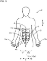
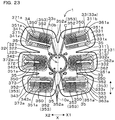
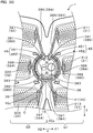
- the abdominal muscles of a person include two rectus abdominis muscles extending in a height direction. Tendinous intersections divide the two rectus abdominis muscles in a direction intersecting the height direction, and three or four compartments are formed in each rectus abdominis muscle.
- the first electrode group and the second electrode group of the electrode unit include four or more electrodes in total.
- the electrodes can be easily attached according to four or more compartments of the rectus abdominis muscles in the muscle electrostimulation device. Therefore, in the compartments corresponding to the electrodes, electrostimulation can be easily applied to motor points (places on the skin where nerves connected to muscles can be easily energized) via the electrodes. As a result, the electrostimulation can be effectively applied to the muscle of each compartment. This can attain advantageous effects of muscle movement (contraction and relaxation) of the rectus abdominis muscles as well as promotion of a blood flow based on the movement of the muscles, increase in the rectus abdominis muscles, and promotion of metabolism.
- the electrodes included in the first electrode group and the electrode included in the second electrode group are lined up in the lateral direction of the person across the main body. Therefore, equivalent electrostimulation can be obtained on the left and the right of the main body, and well-balanced stimulation can be applied to the abdominal muscles.
- the power source is stored in the main body in the muscle electrostimulation device, the power does not have to be supplied from the outside, and the device can be wireless. Therefore, the usability is excellent, and the device can be used at a location without an external power source.
- the first electrode group and the second electrode group are formed to extend from the main body and are provided integrally with the main body. Therefore, the first electrode group and the second electrode group are attached to the abdomen while a specific positional relationship between the groups with respect to the main body is maintained. Accordingly, the electrodes can be easily attached according to the four or more compartments of the rectus abdominis muscles just by attaching the device to the abdomen of the person such that the main body is disposed a little above the umbilicus of the person and such that the center line of the main body is parallel to the central axis of the person. Therefore, the usability is excellent in the muscle electrostimulation device.
- a muscle electrostimulation device that can effectively stimulate abdominal muscles can be provided.
- the muscle electrostimulation device is used by attaching the device to the abdomen of the person such that the main body is disposed a little above the umbilicus of the person, and the center line of the main body is parallel to the central axis of the person. Even if the position of the main body upon the attachment is a position somewhat offset from a little above the umbilicus, the electrostimulation can be applied to the rectus abdominis as long as the electrodes are at positions corresponding to the rectus abdominis muscles.
- the muscle electrostimulation device can be independently attached to the abdomen of the person. A belt covering the abdomen may be wound around the muscle electrostimulation device, while the muscle electrostimulation device is attached to the abdomen. In this case, fall or drop of the muscle electrostimulation device can be surely prevented when the device is used.
- the first electrode group and the second electrode group include the same number of the electrodes. In this case, deviation of the electric current flowing from the electrode unit via the human body can be prevented, and well-balanced electrostimulation can be applied to the muscles of the compartments corresponding to the electrodes in the rectus abdominis muscles.
- the electrodes included in the first electrode group and the electrodes included in the second electrode group be disposed line-symmetrically with respect to the center line when the device is attached to the abdomen.
- the electrodes included in the first electrode group and the electrodes included in the second electrode group can be arranged along the pair of left and right rectus abdominis muscles just by attaching the device to the abdomen of the person such that the center line of the main body is parallel to the central axis of the person. Therefore, well-balanced electrostimulation can be applied to the muscles of the compartments corresponding to the electrodes in the rectus abdominis muscles.
- the first electrode group include a plurality of electrodes arranged in the height direction when the device is attached to the abdomen
- the second electrode group include a plurality of electrodes arranged in the height direction when the device is attached to the abdomen.
- well-balanced electrostimulation can be applied from the electrodes to the muscles of the compartments divided in the height direction of the person in the pair of left and right rectus abdominis muscles just by attaching the device to the abdomen of the person such that the center line of the main body is parallel to the central axis of the person.
- each of the first electrode group and the second electrode group include three electrodes.
- the electrodes are arranged according to six compartments in the abdomen in which the rectus abdominis muscles are divided into six or more parts, and the electrostimulation can be more effectively applied to the muscles of the compartments.
- the first electrode group and the second electrode group be configured to form: an upper electrode pair at uppermost positions; a lower electrode pair at lowermost positions; and a central electrode pair at positions between the upper electrode pair and the lower electrode pair, and the central electrode pair project in its extending direction from the main body more than the upper electrode pair and the lower electrode pair.
- the electrodes can be more accurately arranged according to six compartments of the rectus abdominis muscles in the abdomen in which the rectus abdominis muscles are partitioned into six or more parts, and the electrostimulation can be more effectively applied to the muscles of the compartments.
- the upper electrode pair project in the extending direction from the main body more than the lower electrode pair.
- the electrodes can be more accurately arranged according to six compartments just by attaching the device to the abdomen of the person such that the center line of the main body is parallel to the central axis of the person in the abdomen in which the rectus abdominis muscles are partitioned into six or more parts, and the electrostimulation can be more effectively applied to the muscles of the compartments.
- notches cut toward the main body be formed between the electrodes adjacent to each other in the first electrode group and the second electrode group.
- the electrode unit can be easily deformed according to the movement of the abdomen of the person during the use, and this prevents the electrode unit from falling from the abdomen during the use and prevents the muscle electrostimulation device from dropping off from the abdomen.
- the notches can reduce accumulation of sweat or moisture between the muscle electrostimulation device and the abdomen. This also prevents the electrode unit from falling from the abdomen during the use and prevents the muscle electrostimulation device from dropping off from the abdomen.
- a muscle electrostimulation device according to an embodiment of this example will be described with reference to Figures 1 to 12 .
- a muscle electrostimulation device 1 of this embodiment includes a main body 10, a power source 20, an electrode unit 30, a controller 40, and an operation unit 50 as shown in Figures 1 to 4 and 6 .
- the power source 20 is stored in the main body 10 as shown in Figure 4 .
- the electrode unit 30 is configured to receive power from the power source 20 as shown in Figure 6 .
- the controller 40 controls the supply of power to the electrode unit 30.
- the operation unit 50 is configured to be capable of changing a control mode of the controller 40.
- the electrode unit 30 is brought into contact with an abdomen 3 of a person 2, and the muscle electrostimulation device 1 applies electrostimulation to the abdomen 3.
- the electrode unit 30 includes a first electrode group 31 and a second electrode group 32.
- the first electrode group 31 extends from the main body 10 such that the first electrode group 31 is disposed on a right hand side X1 of the person 2 with respect to a center line 10a parallel to a height direction Y of the person 2 and passing through the center of the main body 10 when the device is attached to the middle of the abdomen 3.
- the second electrode group 32 extends from the main body 10 such that the second electrode group 32 is disposed on a left hand side X2 of the person 2 with respect to the center line 10a when the device is attached to the middle of the abdomen 3.
- the first electrode group 31 and the second electrode group 32 can be electronically connected via the person 2.
- the first electrode group 31 and the second electrode group 32 include four or more (six in Embodiment 1) electrodes in total.
- the muscle electrostimulation device 1 of this embodiment is attached such that a front surface (i.e. an outer surface 121a of an electrode support 121 described later) and a rear surface on the opposite side (i.e. a rear surface 33a that is a surface on the side provided with the electrode unit 30 in a substrate 33 described later) face the abdomen 3 of the person 2.
- the muscle electrostimulation device 1 of this embodiment is attached to the abdomen 3 of the person 2 and used.
- a longitudinal direction of the height of the person 2 is referred to as the height direction Y.
- a direction toward the head in the height direction Y is referred to as an upper side Y1, and a direction toward the legs is referred to as a lower side Y2.
- a direction toward a right hand side 5a of the person 2 from a central axis 2a of the person 2 parallel to the height direction Y and passing through an umbilicus 3a is referred to as the right direction X1
- a direction toward a left hand side 5b of the person 2 from the central axis 2a is referred to as the left direction X2.
- the right direction X1 and the left direction X1 are integrally referred to as a lateral direction X.
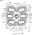
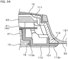
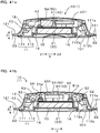
- the main body 10 is provided at the center of the muscle electrostimulation device 1. As shown in Figures 1 and 3 , the main body 10 has a substantially disc shape. As shown in Figure 4 , the main body 10 includes: a case 11 for storing the power source 20 and the controller 40 described later; and a shell forming body 12 attached to the case 11 and forming a shell of the muscle electrostimulation device 1.
- the shell forming body 12 includes: a surface 12b on a side provided with the substrate 33 described later; and an outer surface 12a on the opposite side.
- the shell forming body 12 is made of an elastomer and is made of black silicone in this embodiment.
- the electrode support 121 extends from the shell forming body 12 so as to cover a front surface 33b of the substrate 33. Accordingly, an extending portion 120 including the electrode support 121 and the substrate 33 is formed around the main body 10.
- a colored area 122 in a linear shape substantially along the peripheries of electrodes 311 to 313 and 321 to 323 described later is formed on the outer surface 121a of the electrode support 121. In this embodiment, the colored portion 122 is colored in orange.
- the case 11 includes: a first case 111 in a concave shape; and a second case 112 attached to the first case 111 and forming a container 13 for storing the controller 40 between the second case 112 and the first case 111.
- Both the first case 111 and the second case 112 are made of ABS.
- a rib 112a provided to stand along the periphery of the second case 112 is fitted with the inside of a peripheral portion 111a of the first case 111, and the second case 112 is connected to the first case 111.
- a first cantilever 51a and a second cantilever 51b forming part of the operation unit 50 described later are formed on the first case 111.
- the first cantilever 51a and the second cantilever 51b are formed in a cantilever beam shape by removing part of the wall of the first case 111.
- the first cantilever 51a and the second cantilever 51b are arranged in this order from the upper side to the lower side in the height direction Y.
- both cantilevers 51a and 51b are covered by the shell forming body 12.
- a symbol "+” is formed to protrude immediately above the first cantilever 51a
- a symbol "-” is formed to protrude immediately above the second cantilever 51b, thereby forming an operation surface 54 forming part of the operation unit 50 described later.
- "+" is the upper side in the height direction Y
- "-" is the lower side in the height direction Y, thereby allowing the user to perform ergonomically easy operation.
- a control board 41 forming the controller 40 (see Figure 6 ) is stored in the container 13 formed between the first case 111 and the second case 112.
- the control board 41 is a printed board, and a wiring pattern not shown, electronic components 42, and the like are provided on the control board 41 to form a control circuit.
- the control board 41 is fixed to the first case 111 via four bosses 116 and screws 115 formed to protrude on an inner surface of the first case 111.
- a small surface-mounted speaker 43 is electrically connected to the control board 41.
- Drive voltages of the electronic components 42 and the speaker 43 are both 3.0 V.
- a booster circuit that increases an output voltage of a battery 21 is mounted on the control board 41. Accordingly, the power of the battery 21 is increased to a predetermined voltage (for example, 40 V) and supplied to the electrode unit 30.
- switch mechanisms 52 forming the operation unit 50 are also stored in the container 13.
- the switch mechanisms 52 are electrically connected to the controller 40.
- the switch mechanisms 52 are tactile switches and include switch sections 53 that can be pressed.
- the switch mechanisms 52 are electrically connected to the controller 40.
- the switch mechanisms 52 are arranged immediately below the first cantilever 51a and the second cantilever 51b formed on the first case 111. Accordingly, when the first cantilever 51a is pressed from the outside via the operation surface 54 of the shell forming body 12 covering the first case 111, the first cantilever 51a in the cantilever beam shape is bent to press the switch section 53 of the switch mechanism 52.
- the resilience of the first cantilever 51a in the cantilever beam shape causes the first cantilever 51a to return to the original position.
- the press and the release of the press are performed in the second cantilever 51b.
- a battery holder 14 for holding the battery 21 included in the power source 20 is formed on the second case 112. Accordingly, the power source 20 is embedded in the main body 10.
- the battery 21 can be replaced and can be, for example, a coin battery or a button battery.
- a small and thin coin battery (lithium-ion battery CR2032, nominal voltage 3.0 V) is adopted as the battery 21.
- a battery with a nominal voltage of 3.0 V to 5.0 V can be adopted.
- a lid 15 for preventing the battery 21 from dropping off is detachably attached to the battery holder 14 holding the battery 21.
- the lid 15 has a disc shape one size larger than the battery 21, and an O-ring 16 for sealing between the lid 15 and the second case 112 is fitted around the periphery of the lid 15.
- the battery 21 is electrically connected to the controller 40 via a lead not shown.
- a plurality of linear grooves 113 radially extending from the periphery of the lid 15 are formed on the second case 112 at regular intervals.
- a flange 112b projecting outside of the rib 112a is formed on the second case 112.
- the sheet-shaped substrate 33 is sandwiched between the flange 112b and the peripheral portion 111a of the first case 111 via a double-sided waterproof seal not shown.
- the substrate 33 is made of PET.
- the substrate 33 extends in a sheet shape from the main body 10.
- the front surface 33b of the substrate 33 that is a surface on the side where the operation surface 54 is exposed is covered by the electrode support 121 extended from the shell forming body 12.
- the rear surface 33a opposite to the front surface 33b in the substrate 33 spreads over the entire back side opposite to the surface (front surface) closer to the shell forming body 12 in the muscle electrostimulation device 1.
- the substrate 33 and the electrode support 121 are joined by an adhesive tape and a silicone adhesion treating agent manufactured by 3M company not shown.
- the electrode unit 30 includes the first electrode group 31 and the second electrode group 32.
- the first electrode group 31 extends from the main body 10 so as to be disposed in the right direction X1 on the right hand side 5a of the person 2 with respect to the center line 10a when the device is attached to the abdomen 3.
- the second electrode group 32 extends from the main body 10 so as to be disposed in the left direction X2 on the left hand side 5b of the person 2 with respect to the center line 10a when the device is attached to the abdomen 3.
- the first electrode group 31 includes the first right electrode 311 as a first electrode, the second right electrode 312 as a second electrode, and the third right electrode 313 as a third electrode
- the second electrode group 32 includes the first left electrode 321 as a first electrode, the second left electrode 322 as a second electrode, and the third left electrode 323 as a third electrode.
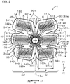
- Each of the electrodes 311 to 313 and 321 to 323 is formed in a substantially rectangular shape with rounded corners.
- a longitudinal direction of each of the electrodes 311 to 313 and 321 to 323 (for example, direction indicated by symbol w in the third right electrode 313 as shown in Figure 2 ) is substantially along the lateral direction X.
- the electrodes 311 to 313 and 321 to 323 all have the same shape.
- h/w can be, for example, 0.40 to 0.95, preferably, 0.50 to 0.80, wherein w is the length in the longitudinal direction, and h is the length in short transverse direction, and in this embodiment, h/w is 0.55.
- a plurality of hexagonal-shaped portions 34 that form no electrode and have predetermined sizes are formed at predetermined intervals inside of each of the electrodes 311 to 313 and 321 to 323.
- Leads 311a, 312a, and 323a for connection to the controller 40 are drawn from the main body 10 and formed on the right electrodes 311, 312, and 313, respectively.
- leads 311a, 312a, and 323a for connection to the controller 40 are drawn from the main body 10 and formed on the left electrodes 321, 322, and 323, respectively.
- the leads 311a to 313a and 321a to 323a are silicone-coated to prevent electric conduction to the outside.
- Portions of the electrodes 311 to 313 and 321 to 323 connected to the leads 311a to 313a and 321a to 323a and adjacent areas of the portions are also silicone-coated to prevent electric conduction to the outside.
- the right electrodes 311 to 313 are connected in parallel to each other, and the left electrodes 321 to 323 are also connected in parallel to each other.
- the electrode unit 30 is formed on the rear surface 33a of the substrate 33. Accordingly, the electrode unit 30 is formed integrally with the main body 10.
- the electrode unit 30 is formed by printing a conductive ink containing a silver paste on the rear surface 33a of the substrate 33.
- the first electrode group 31 and the second electrode group 32 include four or more electrodes in total. In this embodiment, the first electrode group 31 and the second electrode group 32 include the same number of the electrodes 311 to 313 and 321 to 323, respectively, and the number of electrodes is three each. More specifically, the first electrode group 31 includes the first right electrode 311, the second right electrode 312, and the third right electrode 313.
- the plurality of second electrode groups 32 include the first left electrode 321, the second left electrode 322, and the third left electrode 323.
- portions where the first right electrode 311, the second right electrode 312, and the third right electrode 313 are formed are referred to as a first right electrode base part 331, a second right electrode base part 332, and a third right electrode base part 333, respectively, and portions where the first left electrode 321, the second left electrode 322, and the third left electrode 323 are formed are referred to as a first left electrode base part 341, a second left electrode base part 342, and a third left electrode base part 343, respectively.
- a gel pad 35 ("ST-gel (registered trademark)" manufactured by Sekisui Plastics Co., Ltd., model No. SR-RA240/100) is pasted over each of the electrodes 311 to 313 and 321 to 323.
- the gel pads 35 are electroconductive, and the electrodes 311 to 313 and 321 to 323 can energize the abdomen 3 (see Figure 5 ) via the gel pads 35.
- the gel pads 35 are strongly adhesive, and the muscle electrostimulation device 1 is attached to the abdomen 3 via the gel pads 35.
- the gel pads 35 have a shape one size larger than the electrodes 311 to 313 and 321 to 323, and the gel pads 35 separately cover the electrodes 311 to 313 and 321 to 323.
- the gel pads 35 are replaceable and can be appropriately replaced when, for example, the gel pads 35 deteriorate in adhesive force along with the use, are damaged, or become dirty.
- the used gel pads 35 may be replaced with new pads every predetermined time period (for example, every month or two months).
- the first right electrode 311, the second right electrode 312, and the third right electrode 313 extend from the main body 10 so as to be disposed on the right hand side X1 (first area G1) of the person 2 with respect to the center line 10a parallel to the height direction Y of the person 2 (see Figure 5 ) and passing through the center of the main body 10.
- the first right electrode 311, the second right electrode 312, and the third right electrode 313 are arranged in this order from the upper side to the lower side in the height direction Y.
- the first left electrode 321, the second left electrode 322, and the third left electrode 323 extend from the main body 10 so as to be disposed in the direction X2 (second area G2) on the left hand side 5b of the person 2 with respect to the center line 10a.
- the first left electrode 321, the second left electrode 322, and the third left electrode 323 are arranged in this order from the upper side to the lower side in the height direction Y.
- the first electrode group 31 and the second electrode group 32 are disposed line-symmetrically with respect to the center line 10a when the device is attached to the abdomen 3 (see Figure 5 ). More specifically, when the device is attached to the abdomen 3, the first right electrode 311 and the first left electrode 321 are disposed line-symmetrically, the second right electrode 312 and the second left electrode 322 are disposed line-symmetrically, and the third right electrode 313 and the third left electrode 323 are disposed line-symmetrically with respect to the center line 10a.
- the first electrode group 31 and the second electrode group 32 are configured to form: an upper electrode pair 301 including the first right electrode 311 and the first left electrode 321 at uppermost positions of the first electrode group 31 and the second electrode group 32, respectively, in the height direction Y; a lower electrode pair 303 including the third right electrode 313 and the third left electrode 323 at lowermost positions; and a central electrode pair 302 including a pair of the second right electrode 312 and the second left electrode 322 disposed between the upper electrode pair 301 and the lower electrode pair 303. Accordingly, the upper electrode pair 301, the central electrode pair 302, and the lower electrode pair 303 are arranged in this order from the upper side to the lower side in the height direction Y.
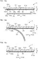
- the central electrode pair 302 protrudes in the extending direction from the main body 10 (lateral direction X) more than the upper electrode pair 301 and the lower electrode pair 303. More specifically, when the device is attached to the abdomen 3, the second right electrode 312 included in the central electrode pair 302 projects in the right direction X1 more than the first right electrode 311 included in the upper electrode pair 301 and the third right electrode 313 included in the lower electrode pair 303. Likewise, the second left electrode 322 included in the central electrode pair 302 projects in the left direction X2 more than the first left electrode 321 included in the upper electrode pair 301 and the third left electrode 323 included in the lower electrode pair 303.
- the upper electrode pair 301 is inclined in a V-shape so as to be deviated upward in the extending direction.
- the electrodes 311 to 313 and 321 to 323 have the same size.
- the right electrode base parts 331 to 333 in the substrate 33 of the electrode unit 30 are larger than the right electrodes 311 to 313, and the left electrode base parts 341 to 343 are larger than the left electrodes 321 to 323.
- the upper electrode pair 301 projects in the extending direction from the main body 10 (lateral direction X) more than the lower electrode pair 302. More specifically, when the device is attached to the abdomen 3, the first right electrode 311 included in the upper electrode pair 301 projects in the right direction X1 more than the third right electrode 313 included in the lower electrode pair 303. Likewise, the first left electrode 321 included in the upper electrode pair 301 projects in the left direction X2 more than the third left electrode 323 included in the lower electrode pair 303.
- a lower peripheral portion 331a of the first right electrode base part 331 protrudes in the right direction X1
- a lower peripheral portion 341a of the first left electrode base part 341 protrudes in the left direction X2.
- a central peripheral portion 332a of the second right electrode base part 332 protrudes a little in the right direction X1, and a central peripheral portion 342a of the second left electrode base part 342 protrudes a little in the left direction X2.
- An upper peripheral portion 333a of the third right electrode base part 333 protrudes in the right direction X1, and a lower peripheral portion 333b of the third right electrode base part 333 protrudes in a lower direction (downward in the Y direction).
- An upper peripheral portion 343a of the third left electrode base part 343 protrudes in the left direction X2, and a lower peripheral portion 343b of the third left electrode base part 343 protrudes in the lower direction.
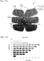
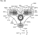
- the configuration of the base parts 331 to 333 and 341 to 343 in the substrate 33 as described above allows visually recognizing that the sizes of the upper electrode pair 301, the central electrode pair 302, and the lower electrode pair 303 are different when the muscle electrostimulation device 1 is viewed from the front side as shown in Figure 1 and allows visually recognizing that the shape resembles the shape of compartments 4a (see Figure 5 ) of rectus abdominis muscles 4 in the abdomen 3.
- This can give the user the impression that the muscle electrostimulation device 1 is suitable for the stimulation of the compartments 4a of the rectus abdominis muscles 4 and can expect an advantageous effect of increasing the motivation of the user in using the muscle electrostimulation device 1.
- the recognition of the shape allows the user to imagine shaped abdomen and six-pack abdominal muscles. This can exert an advantageous effect of visualization training for building the shaped abdomen 3 with six-pack abdominal muscles by using the muscle electrostimulation device 1 (improvement in athletic effects based on visualization training is widely known to the public).
- notches 17 cut toward the main body 10 are formed between the electrodes 311 to 313 and 321 to 323 adjacent to each other in the first electrode group 31 and the second electrode group 32.
- the notches 17 are formed at six positions in total, between the first right electrode 311 and the second right electrode 312, between the second right electrode 312 and the third right electrode 313, between the third right electrode 313 and the third left electrode 323, between the third left electrode 323 and the second left electrode 322, between the second left electrode 322 and the first left electrode 321, and between the first left electrode 321 and the first right electrode 311.
- through holes 18 are formed at four positions around the main body 10.
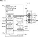
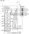
- the muscle electrostimulation device 1 includes a skin detector 402 and a battery voltage detector 406, in addition to the power source 20, the controller 40, and the operation unit 50 inside of the main body 10.
- the skin detector 402 detects whether the electrode unit 30 is in contact with the skin. More specifically, the skin detector 402 is electrically connected to the electrode unit 30 and detects a resistance value between the first electrode group 31 and the second electrode group 32. The skin detector 402 compares the detected value with a preset threshold and detects that the skin is in contact with the first electrode group 31 and the second electrode group 32 when the detected value is smaller than the threshold.
- the battery voltage detector 406 detects a voltage of the battery 21 in the power source 20 and determines whether a detected battery voltage V of the battery 21 in the power source 20 is lower than a predetermined threshold Vm.
- a nominal voltage V0 of the battery 21 is 3.0 V
- the threshold Vm is 2.1 V.
- the power source 20 is provided with the battery 21.
- the controller 40 is provided with an output adjuster 401, a power-off counter 403, a timer 404, an output mode switcher 405, and an output mode memory 405a.
- the output adjuster 401 adjusts an output voltage (output level) in the electrode unit 30.
- a maximum output voltage is set to 40 V, and 100% output voltage is reduced by 2.0 V every time the output level is decreased by 1.
- the output levels include fifteen ranges of level 1 to level 15.
- the power-off counter 403 measures an elapsed time from receipt of a count start signal.
- the timer 404 measures an elapsed time from receipt of an output start signal.
- the output mode switcher 405 switches the output mode in the electrode unit 30 to one of a first output mode, a second output mode, and a third output mode.
- the output mode memory 405a stores the first output mode, the second output mode, and the third output mode.
- Basic waveforms as burst wave patterns including pulse group output suspension periods R1 to R5 are stored in advance in the first output mode, the second output mode, and the third output mode, and the output mode memory 405a configures a burst wave pattern memory.
- the burst wave pattern memory 405a includes description of definition of waveforms of the burst waves on a program.
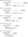
- the output mode memory 405a stores five basic waveforms B1 to B5 shown in Figures 7a to e.
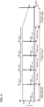
- the basic waveforms B1 to B5 include: a stimulation step P of 1 ms in total in which an electric signal including a bipolar wave with a pulse width of 100 ⁇ s is output five times at intervals of 100 ⁇ s; and stimulation stop steps R1 to R5 of predetermined time periods in which the electric signal is not output.
- the basic waveforms B1 to B5 are repeatedly output in a predetermined combination for a predetermined period, and a burst wave is output in which the stimulation step P is output at a predetermined cycle.
- the voltage value of the electric signal in the stimulation step P is +40 V or -40 V at the maximum.
- the basic waveform B1 (2 Hz) includes the stimulation step P of 1 ms and the stimulation stop step R1 of 499 ms. That is, the basic waveform B1 (2 Hz) is output in which the stimulation step P is output at a frequency of 2 Hz.
- the basic waveform B2 (4 Hz) includes the stimulation step P of 1 ms and the stimulation stop step R2 of 249 ms. That is, the basic waveform B2 (4 Hz) is output in which the stimulation step P is output at a frequency of 4 Hz.
- the basic waveform B3 (8 Hz) includes the stimulation step P of 1 ms and the stimulation stop step R3 of 124 ms. That is, the basic waveform B3 (8 Hz) is output in which the stimulation step P is output at a frequency of 8 Hz.
- the basic waveform B4 (16 Hz) includes the stimulation step P of 1 ms and the stimulation stop step R4 of 61.5 ms. That is, the basic waveform B4 (16 Hz) is output in which the stimulation step P is output at a frequency of 16 Hz.
- the basic waveform B5 (20 Hz) includes the stimulation step P of 1 ms and the stimulation stop step R4 of 49 ms. That is, the basic waveform B5 (20 Hz) is output in which the stimulation step P is output at a frequency of 20 Hz.
- the basic waveforms B1 to B5 include the common stimulation step P, and the length of the stimulation stop steps R1 to R5 are different. Accordingly, the frequencies of occurrence of the stimulation step P in the basic waveforms B1 to B5 are set at the respective predetermined cycles as described above.
- the first to third output modes stored in the output mode memory 405a are formed by combining the basic waveforms B1 to B5 in predetermined formats.
- the first output mode is a warm-up mode for sequentially performing the following first to fourth statuses. Conditions of the statuses are as follows.
- the duration period of the first output mode (i.e. total duration period of first to fourth statuses) is one minute.
- the frequency of the basic waveform gradually increases from 2 Hz to 16 Hz, and the first output mode is called a warm-up mode.
- the frequency of movement of the muscles increases with a gradual increase in the frequency of the burst wave from 2 Hz to 16 Hz, and the muscles and the body are gradually warmed up. This prevents a sudden increase in the blood pressure, a temporary lack of oxygen in the muscles, and the like.
- the gradual warming of the muscles increases the blood flow and increases the flexibility of the muscles. Accordingly, an advantageous effect of the stimulation of the muscles can be more easily obtained in the following training mode. The user can appropriately get used to the stimulation by performing the warm-up mode prior to the training mode, and the sensitivity improves.
- the second output mode is a training mode for sequentially performing the following first to fourth statuses.
- Conditions of the statuses are as follows.
- the duration of the second output mode is twenty minutes. Since the basic waveform B5 at a frequency of 20 Hz is maintained for a predetermined time period, and the state without output or the basic waveform B2 at a frequency of 4 Hz is maintained for a predetermined time period in the second output mode, the second output mode is excellent in effectively stimulating the muscles. Therefore, the second output mode is called a training mode.
- the third output mode is a cool-down mode for sequentially performing the following first to fourth statuses.
- Conditions of the statuses are as follows.
- the output in each status is 100% at the start of the first status and is gradually reduced to 50% at the end of the fourth status as shown in Figure 8 .
- the duration of the third output mode is one minute.
- the frequency of the basic waveform is gradually reduced from 16 Hz to 2 Hz, and the third output mode is called a cool-down mode.
- the frequency of movement of the muscles is reduced with a gradual decrease in the frequency of the burst wave from 16 Hz to 2 Hz, and the warmed muscles and body are gradually cooled down. Fatigue substances generated in the muscles in the preceding training mode are actively discharged from the muscles to prevent the fatigue substances from excessively remaining in the muscles.
- the total time of the sequential execution of the first output mode (warm-up mode), the second output mode (training mode), and the third output mode (cool-down mode) is twenty two minutes.
- a pause time period of two seconds is provided at each of four sections in total between the first output mode and the second output mode and between the statuses in the second output mode as shown in Figure 8 . Therefore, the total time of the entire process including the pause time periods is twenty two minutes and eight seconds.
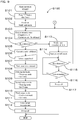
- a main operation flow S100 shown in Figure 9 will be described.
- "+" of the operation surface 54 is pressed for two seconds (S101). Accordingly, the power of the muscle electrostimulation device 1 is turned on to activate the muscle electrostimulation device 1, and the speaker 43 makes a notification sound ("beep") for notifying the activation (SI02). Subsequently, the muscle electrostimulation device 1 is brought into an output standby state, the output level is set to 0, and the input into the operation unit 50 is invalidated (S103).
- the skin detector 402 detects whether the skin is in contact with the electrode unit 30 (SI04). If the skin detector 402 detects that the skin is in contact with the electrode unit 30 (Yes in S104), the operation unit 50 is validated (S105). The output level is input through the operation unit 50 (SI06). The output level is input from the operation surface 54 of the operation unit 50. The output level is incremented by 1 every time "+" of the operation surface 54 of the operation unit 50 is pressed, and the output level is decremented by 1 every time "-" of the operation surface 54 is pressed. When the output level is set, the controller 40 transmits an output start signal to the timer 404, and the timer 404 starts the measurement (S107). The output level can be operated at any time during the use (from the validation of the operation unit 50 to the power-off).
- the output mode in the electrode unit 30 is set to the first output mode (warm-up mode) for one minute after the start (elapsed time 0) of the measurement by the timer 404 (S108).
- the output mode switcher 405 switches the output mode in the electrode unit 30 to the second output mode (training mode) and maintains the second output mode for twenty minutes until the elapsed time is twenty one minutes (S109).
- the output mode switcher 405 switches the output mode in the electrode unit 30 to the third output mode (cool-down mode) and maintains the third output mode for one minute until the elapsed time is twenty two minutes (S110).
- the measurement in the timer 404 is finished (Sill).
- the muscle electrostimulation device 1 is then stopped (S112).
- S108 to S111 are performed to perform one set of the first output mode (warm-up mode), the second output mode (training mode), and the third output mode (cool-down mode), and the process ends. Note that the elapsed time does not include two seconds of each pause time period.
- the skin detector 402 determines that the skin is not in contact with the electrode unit 30 (No in S104)
- the speaker 43 makes a notification sound ("beep, beep, beep") for notifying the determination (S113).
- the power-off counter 403 then starts to measure the elapsed time (S114).
- the skin detector 402 detects whether the electrode unit 30 is in contact with the skin (S115). If the skin detector 402 detects that the skin is in contact with the electrode unit 30, the process returns to step S103 described above, and the state is brought into the output standby state (Yes in S115). On the contrary, if the skin detector 402 determines that the skin is not in contact with the electrode unit 30 (No in S115), whether the elapsed time in the power-off counter 403 exceeds two minutes is determined (S116). If it is determined that the elapsed time in the power-off counter 403 does not exceed two minutes (No in S116), the process returns to S115 again, and the skin detector 402 detects whether the skin is in contact with the electrode unit 30. On the contrary, if it is determined that the elapsed time in the power-off counter 403 exceeds two minutes in S116 (Yes in S116), the power of the muscle electrostimulation device 1 is turned off (S117).
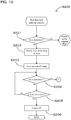
- a skin detection interrupt process S200 is executed as a first interrupt process.
- the skin detection interrupt process S200 is used as a function for automatically turning off the power source when the electrode drops off from the human body in the middle of usage.
- the skin detector 402 first detects whether the skin is in contact with the electrode unit 30 (S201). If the skin detector 402 detects that the skin is in contact with the electrode unit 30 (Yes in S201), the process returns to the original flow in the main operation flow S100.
- the skin detector 402 determines that the skin is not in contact with the electrode unit 30 (No in S201)
- the speaker 43 makes a notification sound ("beep, beep, beep") for notifying the determination (S202).
- the power-off counter 403 then starts to measure the elapsed time (S203).
- the skin detector 402 detects whether the skin is in contact with the electrode unit 30 (S204). If the skin detector 402 detects that the skin is in contact with the electrode unit 30, the process returns to step S103 of the main operation flow S100 (Yes in S204). On the contrary, if the skin detector 402 determines that the skin is not in contact with the electrode unit 30 (No in S204), whether the elapsed time in the power-off counter 403 exceeds two minutes is determined (S205). If it is determined that the elapsed time in the power-off counter 403 does not exceed two minutes (No in S205), the process returns to S204 again, and the skin detector 402 detects whether the skin is in contact with the electrode unit 30. On the contrary, if it is determined in S205 that the elapsed time in the power-off counter 403 exceeds two minutes (Yes in S205), the power of the muscle electrostimulation device 1 is turned off (S206).
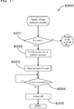
- the battery voltage reduction process S300 is a function for automatically turning off the power source when the battery voltage of the battery 21 is reduced. Accordingly, when, for example, the battery needs to be replaced, the user can easily notice this.
- the battery voltage detector 406 first determines whether the detected battery voltage V of the battery 21 in the power source 20 is lower than the predetermined threshold Vm (S301). If the battery voltage detector 406 determines that the battery voltage V is not lower than the predetermined threshold Vm (No in S301), the process returns to the original flow in the main operation flow S100.
- the battery voltage detector 406 determines that the battery voltage V is lower than the predetermined threshold Vm, the speaker 43 makes a notification sound ("beep, beep, beep") for notifying the determination (S302).
- the controller 40 transmits a count start signal to the power-off counter 403, and the power-off counter 403 starts to measure the elapsed time (S303).
- a suspension process S400 as a third interrupt process that interrupts S105 to S110 in the main operation flow S100 and that is preferentially processed will be described.
- the controller 50 first determines whether the time of the press of the "-" button of the operation surface 54 in the operation unit 50 is equal to or longer than two seconds (S401). If the controller 40 determines that the time of the press of the "-" button is not equal to or longer than two seconds (No in S401), the process returns to the original flow in the main operation flow S100.
- the controller 40 determines that the time of the press of the "-" button is equal to or longer than two seconds (Yes in S401), the speaker 43 makes a notification sound ("beep") of notification for turning off the power source to end the muscle electrostimulation device 1 (S402). The power source is then turned off (S403).
- beep notification sound
- the first electrode group 31 and the second electrode group 32 of the electrode unit 30 include four or more electrodes 311 to 313 and 321 to 323 in total. Furthermore, when the muscle electrostimulation device 1 is attached to the abdomen 3 of the person 2, the first electrode group 31 is disposed on the right hand side X1 (first area S1) of the person 2 with respect to the center line 10a of the main body 10, and the second electrode group 32 is disposed on the left hand side X2 (second area S2) of the person 2 with respect to the center line 10a of the main body 10. Therefore, the electrodes 311 to 313 and 321 to 323 can be easily attached according to four or more compartments in the muscle electrostimulation device 1.
- electrostimulation can be easily applied to motor points (places on the skin where nerves connected to muscles can be easily energized) via the electrodes 311 to 313 and 321 to 323.
- the electrostimulation can be effectively applied to the muscles of the compartments 4a. This can attain advantageous effects of muscle movement (contraction and relaxation) of the rectus abdominis muscles as well as promotion of a blood flow based on the movement of the muscles, increase in the rectus abdominis muscles, and promotion of metabolism.
- the first electrode group 31 is arranged on the right hand side X1 (first area G1), and the second electrode group 32 is arranged on the left hand side X2 (second area G2), the first electrode group 31 and the second electrode group 32 are lined up in the lateral direction X of the person 2 across the main body 10 when the muscle electrostimulation device 1 is attached to the abdomen 3. Therefore, equivalent electrostimulation is applied to the left and the right of the main body 10, and well-balanced stimulation can be applied to the abdominal muscles (rectus abdominis muscles 4).
- the power source 20 is stored in the main body 10, the power does not have to be supplied from the outside, and the muscle electrostimulation device 1 is wireless. Therefore, the usability is excellent, and the device can be used at a location without an external power source.
- the first electrode group 31 and the second electrode group 32 are formed to extend from the main body 10 and are provided integrally with the main body 10. Therefore, the first electrode group 31 and the second electrode group 32 are attached to the abdomen 3 while a specific positional relationship with respect to the main body 10 is maintained. That is, the first right electrode 311 is disposed on the upper side in the right direction X1 of the main body 10 in this embodiment.
- the second right electrode 312 is disposed on the center in the right direction X1 of the main body 10.
- the third right electrode 313 is disposed on the lower side in the right direction X1 of the main body 10.
- the first left electrode 321 is disposed on the upper side in the left direction X2 of the main body 10.
- the second left electrode 322 is disposed on the center in the left direction X2 of the main body 10.
- the third left electrode 323 is disposed on the lower side in the left direction X2 of the main body 10. Accordingly, the first electrode group 31 and the second electrode group 32 can be easily attached according to four or more compartments 4a in the abdominal muscles (rectus abdominis muscles 4) just by attaching the device to the abdomen 3 of the person 2 such that the main body 10 is disposed a little above the umbilicus 3a of the person 2 and such that the center line 10a of the main body 10 is parallel to the central axis 2a of the person 2. Therefore, the usability is excellent in the muscle electrostimulation device 1.
- the first electrode group 31 and the second electrode group 32 include the same number of the electrodes 311 to 313 and 321 and 323. This can prevent deviation of the electric current flowing from the electrode unit 30 through the human body and can apply well-balanced electrostimulation to the muscles of the compartments 4a corresponding to the electrodes 311 to 313 and 321 to 323 in the rectus abdominis muscles 4.
- the right electrodes 311 to 313 included in the first electrode group 31 and the left electrodes 321 to 323 included in the second electrode group 32 are disposed line-symmetrically with respect to the center line 10a when the device is attached to the abdomen 3. Accordingly, when the muscle electrostimulation device 1 is attached to the abdomen 3, the right electrodes 311 to 313 included in the first electrode group 31 and the left electrodes 321 to 323 included in the second electrode group 32 can be arranged along the pair of left and right rectus abdominis muscles 4 just by attaching the device to the abdomen 3 of the person 2 such that the center line 10a of the main body 10 is parallel to the central axis 2a of the person 2. Therefore, well-balanced electrostimulation can be applied to the muscles of the compartments 4a corresponding to the electrodes 311 to 313 and 321 to 323 in the rectus abdominis muscles 4.
- the first electrode group 32 includes the plurality of right electrodes 311 to 313 arranged in the height direction Y when the device is attached to the abdomen 3, and the second electrode group 32 includes the plurality of left electrodes 321 to 323 arranged in the height direction Y when the device is attached to the abdomen 3.
- the electrodes 311 to 313 and 321 to 323 can apply well-balanced electrostimulation to the muscles of the compartments 4a divided in the height direction Y of the person 2 in the pair of left and right rectus abdominis muscles 4 just by attaching the device to the abdomen 3 of the person 2 such that the center line 10a of the main body 10 is parallel to the central axis 2a of the person 2.
- the first electrode group 31 and the second electrode group 32 include three electrodes 311 to 313 and 321 to 323, respectively. Accordingly, the electrostimulation can be more effectively applied to the muscles of the compartments 4a just by attaching the device to the abdomen 3 of the person 2 such that the center line 10a of the main body 10 is parallel to the central axis 2a of the person 2, because the electrodes 311, 312, 313, 321, 322, and 323 are arranged according to the six compartments 4a in the abdomen 3 in which the rectus abdominis muscles 4 are partitioned into six or more parts.
- the first electrode group 31 and the second electrode group 32 are configured to form: the upper electrode pair 301 at uppermost positions of the first electrode group 31 and the second electrode group 32; the lower electrode pair 303 at lowermost positions; and the central electrode pair 302 at positions between the upper electrode pair 301 and the lower electrode pair 303.
- the central electrode pair 302 projects in the extending direction (i.e. lateral direction X) from the main body 10 more than the upper electrode pair 301 and the lower electrode pair 303.
- the electrostimulation can be more effectively applied to the muscles of the compartments 4a just by attaching the device to the abdomen 3 of the person 2 such that the center line 10a of the main body 10 is parallel to the central axis 2a of the person 2, because the electrodes 311, 312, 313, 321, 322, and 323 can be more accurately arranged according to the six compartments 4a in the abdomen 3 in which the rectus abdominis muscles 4 are partitioned into six or more parts.
- the upper electrode pair 301 projects in the extending direction (i.e. lateral direction X) from the main body 10 more than the lower electrode pair 303. Accordingly, the electrodes 311, 312, 313, 321, 322, and 323 can be more accurately arranged according to the six compartments 4a just by attaching the device to the abdomen 3 of the person 2 such that the center line 10a of the main body 10 is parallel to the central axis 2a of the person 2 in the abdomen 3 in which the rectus abdominis muscles 4 are partitioned into six or more parts. Therefore, the electrostimulation can be more effectively applied to the muscles of the compartments 4a.
- the notches 17 cut toward the main body 10 are formed between the electrodes 311 to 313 and 321 to 323 adjacent to each other in the first electrode group 31 and the second electrode group 32. Accordingly, the electrode unit 30 can be easily deformed according to the movement of the abdomen 3 of the person 2 during the use, and this prevents the electrode unit 30 from falling from the abdomen 3 during the use and prevents the muscle electrostimulation device 1 from dropping off from the abdomen 3.
- the notches 17 can also reduce accumulation of sweat and moisture between the muscle electrostimulation device 1 and the abdomen 3. This also prevents the electrode unit 30 from falling from the abdomen 3 during the use and prevents the muscle electrostimulation device 1 from dropping off from the abdomen 3.
- all the electrodes 311 to 313 and 321 to 323 are formed in a substantially rectangular shape with rounded corners.
- the longitudinal direction of the electrodes 311 to 313 and 321 to 323 is substantially along the lateral direction X. Accordingly, since the electrodes 311 to 313 and 321 to 323 spread in the extending direction of the electrodes 311 to 313 and 321 to 323, the electrostimulation can be applied to a wider range, and the electrostimulation can be effectively applied to the rectus abdominis muscles spread into a relatively wide range.
- all the electrodes 311 to 313 and 321 to 323 have the same shape. This prevents deviation of the electric current flowing via the electrodes 311 to 313 and 321 to 323, and well-balanced electrostimulation can be applied to the rectus abdominis muscles 4.
- the grooves 113 are formed on the second case 112.
- the grooves 113 radially and linearly extend from the periphery of the lid 15, and the sweat between the main body 10 and the abdomen 3 can be guided to the outside of the main body 10. This can prevent accumulation of sweat and moisture between the main body 10 and the abdomen 3.
- the through holes 18 are formed around the main body 10. Therefore, the sweat guided to the outside of the main body 10 through the grooves 113 are easily discharged from between the muscle electrostimulation device 1 and the abdomen 3 via the through holes 18.
- the device includes: the main body 10; the plurality of electrode units 30 that output electrostimulation; the power source 20 that supplies power to the electrode units 30; the controller 40 that controls the supply of power by the power source 20; and the operation unit 50 configured to be capable of changing the control mode of the controller 40, and the power source 20 is embedded in the main body 10. Accordingly, the power supplied to the electrode units 30 does not have to be prepared outside, and the device can be easily used outdoors or places away from home where it is difficult to secure the power source. Since a cord or the like for connection to the power source is not necessary, the usability is improved, and the portability is excellent.
- the electrode unit 30 in this embodiment includes the sheet-shaped substrate 33 elongated from the main body 10, the substrate 33 provided with: the plurality of electrodes 311 to 313 and 321 to 323; and the leads 311a to 313a and 321a to 323a for electrically connecting the electrodes 311 to 313 and 321 to 323 and the power source 30 via the controller 40. Accordingly, the electrode unit 30 is formed on the sheet-shaped substrate 30 elongated from the main body 10, and the main body 10 and the electrode unit 30 can be integrated. Therefore, a cord or the like for connecting the main body 10 and the electrode unit 30 is not necessary.
- the muscle electrostimulation device 1 Since the power source is embedded in the main body, and the main body and the electrode unit are integrated, excellent portability can be attained, thereby allowing to use the device in various environments. Since the power source 20, the main body 10, and the electrode unit 30 are integrated, the muscle electrostimulation device 1 can be easily attached to and removed from the human body 2, and particularly, the muscle electrostimulation device 1 can be easily removed even when the muscles are fatigued just after the use of the muscle electrostimulation device 1. Therefore, the muscle electrostimulation device 1 is more suitable for efficiently stimulating the muscles through electrostimulation in various environments.
- the replaceable battery 21 is provided on the power source 20. Accordingly, the power can be supplied just by replacing the battery 21, and the device can be easily used for a longer time than the battery capacity. Accordingly, a power source with an excessively large capacity does not have to be included, and the size of the device can be reduced.
- the battery 21 can be a button battery or a coin battery, and in this embodiment, the battery 21 is a coin battery. Accordingly, the battery 21 is small, and this contributes to the reduction in the size of the muscle electrostimulation device 1. Since the weight can be reduced along with the reduction in the size of the muscle electrostimulation device 1, the electrode unit 30 is unlikely to be fallen or dropped off from the body of the user, and this improves the usability and improves the portability.
- the battery 21 is also thin, and this contributes to the reduction in the thickness of the muscle electrostimulation device 1. Since the muscle electrostimulation device 1 is thin, the user can wear clothes over the muscle electrostimulation device 1 while the device is attached.
- the muscle electrostimulation device 1 can be used during commute to work or school, during housework or work, and in various other situations.
- the button battery has more stable discharge characteristics at a higher operating voltage compared to other dry batteries and the like, and stable operation of the muscle electrostimulation device 1 is possible for a relatively long time.
- the nominal voltage of the battery 21 can be 3.0 to 5.0 V, and the battery 21 of 3.0 V is adopted in this embodiment.
- the drive voltages of the electronic components 42, the speaker 43, and the like included in the muscle electrostimulation device 1 are the same, and a step-down circuit or a booster circuit for driving the electronic components 42 and 43 does not have to be separately provided. This can contribute to the reduction in the size.
- the power source 20 may contain a rechargeable battery instead of the replaceable battery 21.
- a power supply terminal connectable to an external power source may be provided as means for recharging the battery, or a noncontact power supply unit using electromagnetic induction may be provided.
- the battery can be repeatedly used, and expendable supplies can be reduced compared to when a nonchargeable battery is used.
- the substrate 33 provided with the electrode unit 30 is elongated from the main body 10, and the electrode support 121 elongated from the shell forming body 12 is bonded to integrally form the electrode unit 30 and the main body 10.
- the substrate 33 and the main body 10 may be separately formed, and the electrode support 121 and the shell forming body 12 may be separately formed to allow the main body 10 and the electrode unit 30 to be separated from each other when the device is not used.
- the electrode unit 30 can be separated from the main body 10 and replaced with an electrode unit in another format.
- the electrode unit 30 does not include electronic components, and the electrode unit 30 can be separated to easily clean the electrode unit 30.
- the second output mode (training mode) is executed based on the first to fourth statuses shown in Table 2 described above.
- a 2a status shown in Table 4 may be executed between the second status and the third status
- a 3a status shown in Table 4 may be executed between the third status and the fourth status as in the following Variation 1 in the first to fourth statuses equivalent to this embodiment.
- the 2a status and the 3a status are performed as follows.
- the 2a status and the 3a status are added to the second output mode (see Table 2) of this embodiment, and the total time of sequential execution of the first output mode (warm-up mode), the second output mode (training mode), and the third output mode (cool-down mode) shown in Table 4 is twenty three minutes. Note that the total time does not include two seconds of each pause time period.
- the frequency of the basic waveform gradually increases from 4 Hz to 16 Hz in the 2a status, and the change in the frequency at the switch from the 2a status to the third status is smooth. Likewise, the change in the frequency at the switch from the 3a status to the fourth status is smooth.
- the 2a status and the 3a status are added to this embodiment, and the pattern of electrostimulation in the second output mode (training mode) significantly changes. As a result, a reduction in sensitivity as the user gets used to the electrostimulation can be prevented, and the rectus abdominis muscles can be more effectively stimulated.
- the effects equivalent to this embodiment are also attained in this Variation 1 in which the second output mode (training mode) is set in this way.
- the leads 311a to 323a and part (hatched areas indicated by symbol C in Figure 2 ) of the electrodes 311 to 313 and 321 to 323 connected to the leads 311a to 323a are silicone-coated. This can prevent a pain at the energization caused by concentration of electric charge in narrow areas of the leads 311a to 323a and 311a to 323a.
- the silicone-coated areas in the electrodes 311 to 313 and 321 to 323 may be expanded from the hatched areas indicated by symbol C, from the leads 311a to 313a and 321a to 323a to near the centers of the electrodes 311 to 313 and 321 to 323.
- the gel pads 35 with a shape equivalent to this embodiment can also be used. According to this, the areas substantially functioning as electrodes in the electrodes 311 to 313 and 321 to 313 are separated from each other, and the locations provided with the electrostimulation are easily spread in the lateral direction X. As a result, the user can easily recognize that the electrostimulation is applied to a wider range of the abdomen 3, and the sense of usage improves.
- the shapes of the electrodes 311 to 313 and 321 to 323 are similar to the shapes in this embodiment, the external forms of the shapes of the electrodes 311 to 313 and 321 to 323 can be used as guides for pasting the gel pads 35 to predetermined positions, and the gel pads 35 can be easily attached.
- the electrode unit 30 may include four electrodes, and the electrodes may be mounted across a plurality of compartments 4a instead of this.
- the electrode unit 30 may include eight electrodes, and each of the electrodes may correspond to each of the compartments 4a of the rectus abdominis muscles 4 to allow applying electrostimulation to eight compartments 4a.
- the muscle electrostimulation device 1 that can effectively stimulate the abdominal muscles (rectus abdominis muscles 4) can be provided.
- a muscle stimulating method is used, in which the muscles are energized via electrodes attached to the human body to contract and relax the muscles based on electric signals.
- a low frequency signal is particularly effective as an electric signal for contracting the muscles. This is because the muscles start not to contract with an increase in the frequency of the electric signal.
- a low frequency of the electrical signal tends to cause pain due to effects of electric resistance or the like on the surface of the skin of the person.
- a high frequency of the electric signal tends to reduce the effects of the electric resistance or the like and is unlikely to cause pain. Therefore, the user may feel pain on the skin depending on the electric pulse, and there is room for improvement in the sensitivity when the muscle electrostimulation device is used.
- the muscles cannot be efficiently stimulated just by reducing the voltage of the electric pulse or simply increasing the electric frequency in order to alleviate the pain of the user.
- the muscle electrostimulation device 1 of Embodiment 2 is configured as follows in view of the problem. The same symbols are provided to the members equivalent to the members of the muscle electrostimulation device 1 in the preceding embodiment, and the description of the members and the description of the usage mode will not be repeated. When the drawings used in the description of this embodiment are the same as the drawings in the preceding embodiment, the drawings in the preceding embodiment will be used.
- the muscle electrostimulation device 1 of Embodiment 2 is configured to apply electrostimulation to the muscles.
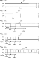
- the electrostimulation is performed by repeatedly outputting the burst waves (basic waveforms B1 to B5 shown in Figure 7 ) including the pulse group output period P and the pulse group output suspension periods R1 to R5 as shown in Figure 13 .
- a plurality of rectangular wave pulse signals S1 to S5 are output with output stop times N1 to N5 being inserted between the signals in the pulse group output period P.
- the pulse group output suspension periods R1 to R5 are longer than the output stop times N1 to N5, and the output of the pulse signals is stopped.
- the output mode memory 405a as a duration memory stores the five burst wave patterns (basic waveforms B1 to B5) shown in Figure 7 .
- the basic waveforms B1 to B5 include the pulse group output period P and the pulse group output suspension periods R1 to R5. That is, the basic waveforms B1 to B5 include the common pulse group output period P, and the lengths of the pulse group output suspension periods R1 to R5 are different.
- the plurality of rectangular wave pulse signals S1 to S5 are output with the output stop times N1 to N5 being inserted between the signals in the pulse group output period P.
- five rectangular wave pulse signals S1 to S5 are output. That is, a first rectangular wave pulse signal S1, a first output stop time N1, a second rectangular wave pulse signal S2, a second output stop time N2, a third rectangular wave pulse signal S3, a third output stop time N3, a fourth rectangular wave pulse signal S4, a fourth output stop time N4, a fifth rectangular wave pulse signal S5, and a fifth output stop time N5 are sequentially executed in the pulse group output period P.
- the pulse widths and the pulse voltages of the rectangular wave pulse signals S1 to S5 are constant, and the durations of the output stop times N1 to N5 are also constant.
- the pulse width of each of the rectangular wave pulse signals S1 to S5 is 100 ⁇ s
- the pulse voltage is 40 V or -40 V during 100% output
- the duration of the output stop times N1 to N5 is 100 ⁇ s. Therefore, the duration of the pulse group output period P is 1 ms.
- the voltage polarities in the rectangular wave pulse signals S1 to S5 are alternately changed according to the output order. That is, the first rectangular wave pulse signal S1, the third rectangular wave pulse signal S3, and the fifth rectangular wave pulse signal S5 have a positive polarity, and the second rectangular wave pulse signal S2 and the fourth rectangular wave pulse signal S4 have a negative polarity.
- the pulse width of each of the rectangular wave pulse signals S1 to S5 and the duration of each of the output stop times N1 to N5 in the pulse group output period P are 100 ⁇ s. Therefore, the pulse cycle of each of the rectangular wave pulse signals S1 to S5 in the pulse group output period P is 200 ⁇ s, which is sufficiently short. Therefore, the user recognizes the rectangular wave pulse signals S1 to S5 as one electrostimulation. Note that the frequency of each of the rectangular wave pulse signals S1 to S5 in the pulse group output period P is 5,000 Hz.
- pulse signals are not output in the pulse group output suspension periods R1 to R5.
- the durations of the pulse group output suspension periods R1 to R5 are longer than the duration of the pulse group output period P.
- the duration of the pulse group output period P is 1 ms
- the durations of the pulse group output suspension periods R1 to R5 are 499 ms, 249 ms, 124 ms, 61.5 ms, and 49 ms, respectively, as shown in Figure 7 .
- the pulse group output suspension periods R1 to R5 have durations significantly longer than the output stop time in the pulse group output period P.
- a first burst wave (2 Hz) includes the pulse group output period P of 1 ms and the pulse group output suspension period R1 of 499 ms as shown in Figure 13 . That is, the pulse group output period P is output at a frequency of 2 Hz in the first burst wave (2 Hz).
- a second burst wave (4 Hz) includes the pulse group output period P of 1 ms and the pulse group output suspension period R2 of 249 ms. That is, the pulse group output period P is output at a frequency of 4 Hz in the second burst wave (4 Hz).
- a third burst wave (8 Hz) includes the pulse group output period P of 1 ms and the pulse group output suspension period R3 of 124 ms. That is, the pulse group output period P is output at a frequency of 8 Hz in the third burst wave (8 Hz).
- a fourth burst wave (16 Hz) includes the pulse group output period P of 1 ms and the pulse group output suspension period R4 of 61.5 ms. That is, the pulse group output period P is output at a frequency of 16 Hz in the fourth burst wave (16 Hz).
- a fifth burst wave (20 Hz) includes the pulse group output period P of 1 ms and the pulse group output suspension period R5 of 49 ms. That is, the pulse group output period P is output at a frequency of 20 Hz in the fifth burst wave (20 Hz).
- the basic waveforms B1 to B5 are repeatedly output in a predetermined combination for a predetermined time period, and predetermined burst waves are output as shown in Figures 13a to e.
- the user recognizes the plurality of rectangular wave pulse signals S1 to S5 in the pulse group output period P as one electrostimulation, and electrostimulation at a frequency of 2 Hz is output in the first burst wave in which the basic waveform B1 is repeated as shown in Figure 8a .
- electrostimulation at a frequency of 4 Hz is output in the second burst wave in which the basic waveform B2 is repeated
- electrostimulation at a frequency of 8 Hz is output in the third burst wave in which the basic waveform B3 is repeated
- electrostimulation at a frequency of 16 Hz is output in the fourth burst wave in which the basic waveform B4 is repeated
- electrostimulation at a frequency of 20 Hz is output in the fifth burst wave in which the basic waveform B5 is repeated.
- the first to third output modes stored in the output mode memory 405a as a duration memory is configured by appropriately selecting the basic waveforms B1 to B5 stored in the output mode memory 405a and combining the burst waves at predetermined frequencies.
- the first output mode (warm-up mode), the second output mode (training mode), and the third output mode (cool-down mode) are carried out as in the case of Embodiment 1.
- the conditions of the statuses in the first output mode are as follows as shown in Table 1 described above.
- the duration period of the first output mode (i.e. total duration period of first to fourth statuses) is one minute.
- the frequency of the burst wave gradually increases from 2 Hz to 16 Hz.
- the duration of the second output mode is twenty minutes. Since the fifth burst wave at a frequency of 20 Hz is maintained for a predetermined time period, and the state without output or the second burst wave at a frequency of 4 Hz is maintained for a predetermined time period in the second output mode, the second output mode is excellent in effectively stimulating the muscles.
- the third output mode is a cool-down mode for sequentially performing the following first to fourth statuses.
- Conditions of the statuses are as follows.
- the output in each status is 100% at the start of the first status and is gradually reduced to 50% at the end of the fourth status as shown in Figure 9 .
- the duration of the third output mode is one minute.
- the frequency of the burst wave is gradually reduced from 16 Hz to 2 Hz.
- the total time of the sequential execution of the first output mode (warm-up mode), the second output mode (training mode), and the third output mode (cool-down mode) is twenty two minutes.
- a pause time period of two seconds is provided at each of four positions in total between the first output mode and the second output mode and between the statuses in the second output mode as shown in Figure 9 . Therefore, the total time of the entire process including the pause time periods is twenty two minutes and eight seconds.
- the plurality of rectangular wave pulse signals S1 to S5 are output with the output stop times N1 to N5 being inserted between the signals in the pulse group output period P in the first to fifth burst waves forming the electrostimulation. Therefore, the rectangular wave pulse signals S1 to S5 are divided into a plurality of parts in the pulse group output period P. Accordingly, compared to when the rectangular wave pulse signals S1 to S5 are continuously output without the division in the pulse group output period P, the pulse width of each of the rectangular wave pulse signals S1 to S5 can be reduced while the same total output time of the rectangular wave pulse signals S1 to S5 is maintained.
- the pain of the user can be alleviated, while the electrostimulation output from the muscle electrostimulation device 1 and flowing in the muscles or the nerves connected to the muscles is maintained, and the sensitivity in using the muscle electrostimulation device 1 can be improved.
- the pulse group output period P is configured by outputting the plurality of rectangular wave pulse signals S1 to S5 with the output stop times N1 to N5 being inserted between the signals in the burst waves (basic waveforms B1 to B5), the time period P for outputting the pulse is the same as in a burst wave including a pulse output time period for continuously outputting the pulse for the same time period as the pulse group output period P. Therefore, sensitivity close to the sensitivity of the burst waves including the pulse output time period without the insertion of the output stop times can also be obtained in the burst waves including the pulse group output period P with the output stop times N1 to N5 being inserted.
- the plurality of rectangular wave pulse signals S1 to S5 are output with the output stop times N1 to N5 being inserted between the signals in the pulse group output period P, and the duration of the pulse group output period P is a sum of the pulse widths of the plurality of rectangular wave pulse signals S1 to S5 and all the output stop times N1 to N5. Therefore, compared to when the rectangular wave pulse signals S1 to S5 are continuously output without the division during the duration of the pulse group output period P, the actual pulse signal output time is reduced by the output stop times N1 to N5 while the same duration of the pulse group output period P is maintained, and the power consumption can be reduced. This contributes to the reduction in the size of the device because the device can be driven by a power source with a small capacity.
- the burst waves forming the electrostimulation include the pulse group output period P and the pulse group output suspension periods R1 to R5, and the durations of the pulse group output suspension periods R1 to R5 are longer than the output stop times N1 to N5 in the pulse group output period P.
- the burst waves include the pulse group output suspension periods R1 to R5, and the frequencies of the burst waves can be easily set to desired values just by changing the durations of the pulse group output suspension periods R1 to R5 to predetermined lengths without changing the pulse group output period P. This facilitates controlling the output of the electrostimulation including the burst waves at frequencies suitable for contracting and relaxing the muscles, and the muscles can be efficiently stimulated.
- the pulse group output period P includes the rectangular wave pulse signals S1 to S5 with polarities different from each other. Accordingly, the deviation of the electric charge can be easily eliminated in one burst wave (basic waveforms B1 to B5), and the pain of the user can be further alleviated. As a result, the sensitivity and the usefulness in using the muscle electrostimulation device 1 can be further improved.
- the five rectangular wave pulse signals S1 to S5 output in a first pulse group output period P in the first burst wave are sequentially output in order of "positive, negative, positive, negative, positive" as in this example
- the five rectangular wave pulse signals output in a second pulse group output period in the second burst wave occurring subsequent to the first burst wave can be output in order of "negative, positive, negative, positive, negative".
- the deviation of the electric charge in the first burst wave can be surely eliminated by the second burst wave, and the pain of the user can be further alleviated.
- the polarities of the plurality of rectangular wave pulse signals S1 to S5 output in the first pulse group output period P can be just inverted (potentials are inverted) for the second pulse group output period, and the control load can be alleviated compared to when the polarities of individual rectangular wave pulse signals in each pulse group output period are separately controlled.
- the same pulse group output period P includes the rectangular wave pulse signals S1, S3 and S5 and the rectangular wave pulse signals S2 and S4 with polarities different from each other in this embodiment, the following is possible instead of this.
- the polarities of all the rectangular wave pulse signals S1 to S5 in the first pulse group output period P of the first burst wave may be positive, the polarities of all the rectangular wave pulse signals in the second pulse group output period of the second burst wave occurring with the pulse group output suspension periods R1 to R5 being inserted between the signals following the first burst wave may be negative, and the first burst wave and the second burst wave may be repeated.
- the repeatedly output burst waves as a whole include the rectangular wave pulse signals with polarities different from each other.
- the deviation of the electric charge in the first burst wave can also be surely eliminated by the second burst wave, and the pain of the user can be further alleviated.
- the durations of the pulse group output suspension periods R1 to R5 are longer than the duration (1 ms) of the pulse group output period P. Accordingly, the intervals of the pulse group output periods P repeatedly output in the burst waves are sufficiently secured by the pulse group output suspension periods R1 to R5, and this allows the user to easily recognize the plurality of rectangular wave pulse signals S1 to S5 in the pulse group output periods P as one electrostimulation. As a result, low-frequency (2 to 20 Hz in this embodiment) burst waves can be easily output from the high-frequency (frequency of 5,000 Hz in this embodiment) rectangular wave pulse signals S1 to S5, and electrostimulation suitable for stimulating the muscles can be output.
- the device includes: the burst wave pattern memory (output mode memory 405a) storing in advance the plurality of burst wave patterns (basic waveforms B1 to B5) with frequencies different from each other, wherein the durations of the pulse group output periods P are the same, and the durations of the pulse group output suspension periods R1 to R5 are different; and the frequency setting unit (output mode switcher 405) that selects one of the plurality of burst wave patterns (basic waveforms B1 to B5) stored in the burst wave pattern memory (output mode memory 405a) to set the frequency of the burst wave in the electrostimulation.
- the burst wave pattern memory output mode memory 405a
- the frequency setting unit that selects one of the plurality of burst wave patterns (basic waveforms B1 to B5) stored in the burst wave pattern memory (output mode memory 405a) to set the frequency of the burst wave in the electrostimulation.
- the frequency setting unit (output mode switcher 405) can just select a predetermined pattern from the burst wave patterns stored in the burst wave pattern memory (output mode memory 405a) to change the frequency of the burst wave, and the frequency of the burst wave can be easily changed. Accordingly, the muscle electrostimulation device 1 is suitable for efficiently stimulating the muscles.
- the pulse widths of the rectangular pulse signals S1 to S5 and the output stop times N1 to N5 in the burst waves are constant. Accordingly, the electrostimulation applied to the muscles can be easily changed based on the frequencies of the burst waves. This facilitates adjusting the electrostimulation based on the frequencies of the burst waves and facilitates outputting the electrostimulation suitable for effectively stimulating the muscles.
- the electrode unit 30 includes three or more electrodes 311 to 313 and 321 to 323. As described above, since the pulse group output period P includes the output stop times N1 to N5, the power consumption is reduced, and sufficient electrostimulation can be applied even in this configuration including three or more electrodes 311 to 313 and 321 to 323. Accordingly, the electrostimulation can be applied to a wide range of muscles, and the muscles can be efficiently stimulated.
- the muscle electrostimulation device 1 can be provided, the device capable of attaining the effects equivalent to the effects in Embodiment 1, capable of improving the sensitivity when the device is used, and capable of efficiently stimulating the muscles.
- JP-A-2009-142624 discloses a muscle electrostimulation device that uses an electric signal to stimulate muscles, the device outputting electrostimulation that repeats an output period and a non-output period, wherein a pulsed electric signal belonging to a frequency band of 4 to 20 Hz selected by the user is output for a predetermined time in the output period, and the electric signal is not output for a predetermined time in the non-output period.
- the device has an advantageous effect of promoting the blood flow, increasing the muscles, or promoting the metabolism.
- the muscle electrostimulation device 1 of Embodiment 3 is configured as follows in view of the problems. The same symbols are provided to the members equivalent to the members of the muscle electrostimulation device 1 in the preceding embodiments, and the description of the members and the description of the usage mode will not be repeated. When the drawings used in the description of this embodiment are the same as the drawings in the preceding embodiments, the drawings in the preceding embodiments will be used.
- the muscle electrostimulation device 1 of Embodiment 3 is configured to apply electrostimulation to the muscles.
- the electrostimulation alternately repeats: a first output period (2-1, 3-1, 4-1 in Table 5 described later) for outputting a first electric signal (fifth burst wave shown in Figure 13 ) causing at least one of incomplete tetanus and complete tetanus of muscles; and a second output period (2-2, 3-2, 4-2 in Table 5 described later) for outputting a second electric signal (second burst wave) causing muscle twitching.
- the first output mode (warm-up mode), the second output mode (training mode), and the third output mode (cool-down mode) are carried out in the muscle electrostimulation device 1 of Embodiment 3.
- the second output mode of this embodiment is substantially the same as in the cases of Embodiment 1 and Embodiment 2, each of the first to fourth statuses in the second output mode is divided into the first output period (1-1, 2-1, 3-1, 4-1) and the second output period (1-2, 2-2, 3-2, 4-2) for the convenience as shown in Table 5.
- the second output mode in Embodiment 3 is a training mode for sequentially performing the following first to fourth statuses as shown in Table 5.
- the second output mode is substantially the same as in the cases of Embodiment 1 and Embodiment 2, and the conditions of the statuses are as follows.
- the fifth burst wave (20 Hz) shown in Figure 13e and the second burst wave (4 Hz) shown in Figure 13b are repeatedly output in the second to fourth statuses as described above (see Figure 13 ).
- the fifth burst wave (20 Hz) with a frequency in a range of 15 Hz or more and 30 Hz or less is an electric signal for causing incomplete tetanus of muscles.
- the second burst wave (4 Hz) with a frequency in a range of less than 15 Hz is an electric signal for causing muscle twitching.
- electrostimulation that alternately repeats the first output period (2-1 in Table 2) and the second output period (2-2 in Table 2) is output in the second status of the second output mode, wherein the fifth burst wave (20 Hz) as a first electric signal for causing incomplete tetanus of muscles is output in the first output period, and the second burst wave (4 Hz) as a second electric signal for causing muscle twitching is output in the second output period.
- electrostimulation that alternately repeats the first output period (3-1) and the second output period (3-2) is output in the third status of the second output mode, and electrostimulation that alternately repeats the first output period (4-1) and the second output period (4-2) is output in the fourth status.
- the signal is not limited to this, and a burst wave with a frequency in a range of 15 Hz or more and 30 Hz or less can be adopted as a first electric signal.
- the duration of the first output period is three seconds in the second status, four seconds in the third status, and five seconds in the fourth status in this embodiment as described above.
- the duration of the second output period is two seconds in all the second to fourth statuses. In this way, the duration of the first output period is longer than the duration of the second output period in this embodiment.
- the durations of the first output period and the second output period are not limited to these, and the duration of the entire electrostimulation, the duration of the output mode, and the like can be taken into account to appropriately set the durations.
- the fifth burst wave (20 Hz) as a first electric signal includes a signal with a positive polarity and a signal with a negative polarity.
- the second burst wave (4 Hz) as a second electric signal also includes a signal with a positive polarity and a signal with a negative polarity as shown in Figures 13b and 14 .
- the output electrostimulation alternately repeats the first output period (2-1, 3-1, 4-1) and the second output period (2-2, 3-2, 4-2).
- the muscles subjected to the electrostimulation are first continuously contracted by the incomplete tetanus or the complete tetanus (incomplete tetanus in this embodiment) based on the fifth burst wave (20 Hz) as a first electric signal in the first output period (2-1, 3-1, 4-1), and the muscles can be effectively trained. Accordingly, the muscles can be built up. Along with this, fatigue substances are generated in the muscles.
- the blood circulation in the muscles is promoted by twitching based on the second burst wave (4 Hz) as a second electric signal in the second output period (2-2, 3-2, 4-2), and the fatigue substances generated in the first output period (2-1, 3-1, 4-1) are actively discharged from the muscles.
- the first output period (2-1, 3-1, 4-1) comes again, and the building of muscles by the incomplete tetanus or the complete tetanus and the promotion to discharge the fatigue substances based on the promotion of the blood circulation by twitching in the second output period (2-2, 3-2, 4-2) are sequentially performed.
- the muscle electrostimulation device 1 of this embodiment is continuously used, the fatigue substances are unlikely to accumulate in the muscles, and the muscles can be efficiently stimulated. Furthermore, since the burden of the user is alleviated, the sense of usage is excellent even when the device is used for a long time, and this can prompt the user for active and continuous usage.
- the fifth burst wave (20 Hz) as a first electric signal has a frequency in a range of 15 Hz or more and 30 Hz or less
- the second burst wave (4 Hz) as a second electric signal has a frequency in a range of less than 15 Hz. Accordingly, the fifth burst wave (20 Hz) as a first electric signal can cause the incomplete tetanus in the muscles in the first output period (2-1, 3-1, 4-1)
- the second burst wave (4 Hz) as a second electric signal can stably cause the muscle twitching in the second output period (2-2, 3-2, 4-2).
- the muscles can be appropriately contracted without excessively contracting the muscles in the first output period (2-1, 3-1, 4-1).
- the fatigue substances generated in the first output period (2-1, 3-1, 4-1) are discharged from the muscles in the second output period (2-2, 3-2, 4-2), and the accumulation of the fatigue substances is prevented even when the device is continuously used.
- the fifth burst wave (20 Hz) for causing the incomplete tetanus in the muscles is adopted as a first electric signal in this embodiment
- the fourth burst wave (16 Hz) for causing the incomplete tetanus in the muscles may be similarly adopted instead of this. In this case, the effects equivalent to this embodiment are also attained.
- the electric signal for causing the incomplete tetanus in the muscles is adopted as a first electric signal in the first output period (2-1, 3-1, 4-1)
- an electric signal for causing the complete tetanus in the muscles may be adopted as a first electric signal in the first output period (2-1, 3-1, 4-1).
- the effects equivalent to this embodiment are attained, except for the effects obtained when the first electric signal is an electric signal for causing the incomplete tetanus.
- each of the fifth burst wave (20 Hz) as a first electric signal and the second burst wave (4 Hz) as a second electric signal includes a signal with a positive polarity and a signal with a negative polarity, respectively. Accordingly, the deviation of the electric charge in the electrostimulation can be easily eliminated, and the pain of the user can be further alleviated. As a result, the sensitivity in the use of the muscle electrostimulation device 1 of this embodiment can be further improved.
- the duration of the first output period (2-1, 3-1, 4-1) is longer than the duration of the second output period (2-2, 3-2, 4-2). Accordingly, the first output period (2-1, 3-1, 4-1) is sufficiently secured in the output electrostimulation, and the advantageous effect of building the muscles is further increased.
- the burst waves include the rectangular wave pulse signals S1 to S5 as electric signals divided into a plurality of parts.
- the burst waves (basic waveforms B1 to B5) are recognized as one electric signal in the muscles.
- the durations (pulse widths) of divided individual electric signals P1 to P5 can be smaller than the duration of a continuous electric signal that is not divided, and the pain on the skin of the user can be alleviated. Therefore, the sensitivity of the user can be improved.
- the output stop times N1 to N5 divide the electric signal of the pulse group output period P into the plurality of rectangular wave pulse signals S1 to S5, and the continuous energization time (i.e. pulse width) in the pulse group output period P is short.
- the positive polarity and the negative polarity alternately occur in the rectangular wave pulse signals S1 to S5 in the same pulse group output period P so that the deviation of the electric charge is cancelled out, and the rectangular wave pulse signals S1 to S5 with inverted phases come subsequent to the rectangular wave pulse signals S1 to S5 in the pulse group output period P.
- continuous energization time with the electric charge deviated to one of positive and negative is significantly short in the electrodes 311 to 323.
- the silver contained in the silver paste as a formation material of the electrodes 311 to 323 is easily discolored and darkened due to sulfurization caused by sulfur components such as sulfurous acid gas in the air.
- the positive polarity and the negative polarity alternately occur in the rectangular wave pulse signals S1 to S5 to sequentially cancel out the deviation of the electric charge in this embodiment as described above, and the continuous energization time in which the electric charge is deviated to one of positive and negative is significantly short, the sulfurization can be prevented. This can effectively prevent discoloring and darkening of the electrodes 311 to 323.
- the electrodes may be discolored and darkened by oxidation or chlorination of the silver contained in the silver paste, this can also be prevented likewise.
- the muscle electrostimulation device 1 can be provided, the device capable of attaining the effects equivalent to the effects in Embodiment 1, capable of efficiently stimulating the muscles, capable of obtaining an excellent sense of usage even when the device is used for a long time, and capable of prompting the user for active and continuous usage.
- Figures 15 and 16 show Reference Example 1 provided with a muscle electrostimulation device 900 including two electrodes.
- Reference Example 1 includes two electrodes 311 and 321 configured in the same way, but one size larger than the electrodes 311 and 321 of Embodiments 1 to 3.
- the same symbols are provided to the constituent elements equivalent to the constituent elements of Embodiments 1 to 3, and the description will not be repeated.
- the effects equivalent to the effects in Embodiment 3 are also attained, except for the effects obtained when more than two electrodes are provided.
- the muscle electrostimulation device 900 of Reference Example 1 since the number of electrodes 311 and 321 is smaller than when the number of electrodes is six (see Figure 2 ), the power consumption per electrode can be large, and the electrodes 311 and 321 are one size larger. Accordingly, the range that one electrode can apply electrostimulation is expanded, and muscles of a large part, such as an arm and a thigh, can be easily stimulated.
- the muscle electrostimulation device disclosed in Patent Document 1 does not require an external power source, and the operation unit and the pair of electrodes are provided integrally with the main body, a cord or the like for connecting them is not provided. Therefore, while the pair of electrodes are attached to the human body, and the muscle electrostimulation device is attached to the human body, it is easy to wear clothes over the device, and the device can be easily used outdoors, for example.
- the muscle electrostimulation device may be seen through the clothes.
- the outer surface of the muscle electrostimulation device has a large area in a bright color such as white, the muscle electrostimulation device can be more easily seen through the clothes. Therefore, there is a problem that the muscle electrostimulation device cannot be used without hesitation at a location, such as a place away from home, where the device may attract people's attention.
- the outer surface of the muscle electrostimulation device has a large area in a bright color such as white, the light is reflected and is unlikely to be absorbed compared to when the outer surface has a large area in a dark color such as black, and the muscle electrostimulation device is relatively unlikely to be warmed even when the light is received. Accordingly, there is room for improvement in warming the muscles to promote the blood circulation in order to increase the discharge effect of wastes in the muscles.
- the muscle electrostimulation device 1 of Embodiment 4 is configured as follows in view of the problems. The same symbols are provided to the members equivalent to the members of the muscle electrostimulation device 1 in the preceding embodiments, and the description of the members and the description of the usage mode will not be repeated. When the drawings used in the description of this embodiment are the same as the drawings in the preceding embodiments, the drawings in the preceding embodiments will be used.
- the muscle electrostimulation device 1 of Embodiment 4 includes the main body 10, the power source 20, the electrode unit 30, the controller 40, and the operation unit 50 as in the case of Embodiment 1 shown in Figures 1 to 4 and 6 .
- the power source 20 is stored in the main body 10.
- the electrode unit 30 receives power from the power source 20.
- the controller 40 controls the supply of power to the electrode unit 30.
- the operation unit 50 is configured to be capable of changing the control mode of the controller 40.
- the electrode unit 30 is brought into contact with the person 2, and the muscle electrostimulation device 1 applies electrostimulation to the human body 2 as shown in Figure 5 .
- the electrode unit 30 is formed integrally with the main body 10 as in the case of Embodiment 1 shown in Figures 2 and 3 .
- the shell forming body 12 includes the surface 12b on the side provided with the substrate 33 described later and the outer surface 12a on the opposite side.
- the shell forming body 12 is made of an elastomer and is made of black silicone in this embodiment.
- the electrode support 121 extends from the shell forming body 12 so as to cover the front surface 33b of the substrate 33.
- the colored area 122 in a linear shape substantially along the periphery of the electrodes 311 to 313 and 321 to 323 is formed on the outer surfaces 12a and 121a of the electrode support 121. In this embodiment, the colored area 122 is colored in orange.
- the outer surfaces 12a and 121a also include colored areas (other colored areas) displaying a product name, a brand name, or other characters or symbols. Areas other than the colored area 122 and the other colored areas are not colored on the outer surfaces 12a and 121a, and the formation material of the shell forming body 12 and the electrode support 121 are revealed. The proportion of the total of the colored area 122 and the other colored areas on the outer surfaces 12a and 121a is less than 30%. That is, in 70% or more of the areas on the outer surfaces 12a and 121a, the elastomer as a formation material of the shell forming body 12 and the electrode support 121 is revealed without being colored, and the areas have a dark color (black in this embodiment).
- the colored area 122 is an area with a color different from the areas other than the colored area 122, and the colored area 122 can be formed by applying or printing an ink in a predetermined color on the area, for example. Instead of this, the colored area 122 may be formed by a member with a color different from the areas other than the colored area 122 to thereby form the colored area 122 without applying or printing the ink.
- the dark color in this embodiment is a color with a lightness of 5.0 or less in a Munsell color system (JIS Z8721:1993) defined in the Japanese Industrial Standards.
- the areas in the dark color occupying 70% or more of the outer surfaces 12a and 121a have a lightness of 5.0 or less in the Munsell color system, and the lightness is preferably 4.0 or less, more preferably, 3.0 or less.
- the chroma of the areas in the dark color occupying 70% or more of the outer surface 12a and 121a is, for example, 3.0 or less, preferably, 2.0 or less, in the Munsell color system.
- the hue in the Munsell color system of the areas in the dark color occupying 70% or more of the outer surfaces 12a and 121a is not particularly limited, and the hue can be an arbitrary value.
- the lightness, the chroma, and the hue in the Munsell color system of the areas in the dark color can be measured by a colorimeter based on the Japanese Industrial Standards.
- the lightness of the colored area 122 is 6.5 to 7.0, and the chroma is 12 to 13.5 in the Munsell color system (see Figure 17b showing the relationship between the lightness and the chroma in hue 5YR) on the outer surfaces 12a and 121a.
- the lightness of the areas other than the colored area 122 and the other character areas is 1.0 to 2.0, and the chroma is 0.
- Figures 17a and 17b are actually colored, the drawings cannot be expressed in colors, and Figures 17a and 17b are expressed by a grayscale.
- the area in the dark color can be measured by using color systems other than the Munsell color system, such as CIE 1976 L*a*b (JIS Z8781-4:2013), L*C*h color system, Hunter Lab color system, and XYZ (Yxy) color system.
- the color systems can be mutually converted. Therefore, even when the area in the dark color is measured by the other color system, the lightness, the chroma, and the hue can be converted and expressed by the Munsell color system.
- the electrode unit 30 is formed integrally with the main body 10 according to the muscle electrostimulation device 1 of this embodiment, a cord or the like for connecting the electrode unit 30 and the main body 10 is not necessary, and the electrode unit 30 and the main body 10 are integrally attached to the human body when the device is used. Therefore, it is easy to wear clothes over the muscle electrostimulation device 1 while the device is attached.
- 70% or more of the areas of the outer surfaces 12a and 121a that can be visually recognized from the outside while the device is attached to the human body 2 has the dark color. Therefore, the light is unlikely to be reflected compared to the bright color such as white, and this prevents the muscle electrostimulation device 1 from being seen through the clothes. Accordingly, the muscle electrostimulation device 1 can be used without hesitation at a location, such as a place away from home, where the device may attract people's attention.
- the muscle electrostimulation device 1 Since 70% or more of the areas on the outer surfaces 12a and 121a has the dark color according to the muscle electrostimulation device 1 of this embodiment, the light is easily absorbed compared to the bright color such as white, and the muscle electrostimulation device 1 is relatively easily warmed by receiving the light. Therefore, the muscle electrostimulation device 1 is relatively quickly warmed by directly receiving the light during the use or receiving the light transmitted through the clothes. Accordingly, when the muscles are not warmed, the muscle electrostimulation device 1 warms the muscles, and the blood circulation of the muscles is promoted. As a result, the wastes generated by the contraction of the muscles can be actively discharged from the muscles.
- the electrode unit 30 in this embodiment includes the sheet-shaped substrate 33 elongated from the main body 10, the substrate 33 provided with: the plurality of electrodes 311 to 323; and the leads 311a to 313a and 321a to 323a for electrically connecting the electrodes 311 to 323 and the power source 20 via the controller 40.
- the outer surfaces 12a and 121a are formed by: the shell forming body 12 forming the shell of the main body 10; and the electrode support 121 extended from the shell forming body 12 and formed opposite to the side provided with the electrodes 311 to 323 in the substrate 33.
- the electrode unit 30 is formed on the sheet-shaped substrate 33 elongated from the main body 10, and the main body 10 and the electrode unit 30 can be integrated by a simple configuration and can be easily formed thin. Therefore, the device is not conspicuous through the clothes even when the user wears the clothes while the device is attached to the human body 2, and the device can be used without hesitation at a location where the device may attract people's attention. Since the device can be easily formed thin, the portability is also excellent.
- the shell forming body 12 and the electrode support 121 are made of an elastomer in a dark color.
- the elastomer as a formation material of the shell forming body 12 and the electrode support 121 is revealed on the outer surfaces 12a and 121a, and the outer surfaces 12a and 121a have a dark color. Accordingly, the outer surfaces 12a and 121a can have a dark color without special coloring, and the manufacturing cost can be reduced.
- the elastomer in a dark color forming the shell forming body 12 and the electrode support 121 is a silicone resin in a dark color.
- the shell of the muscle electrostimulation device 1 of this embodiment is formed by a silicone resin with a relatively low thermal conductivity. Therefore, since the shell forming body 12 and the electrode support 121 are easily warmed through the reception of light by the outer surfaces 12a and 121a in a dark color, and the shell forming body 12 and the electrode support 121 are formed by a silicone resin with a relatively low thermal conductivity, the shell forming body 12 and the electrode support 121 can be easily maintained in a warm state. Accordingly, the blood circulation in the muscles is further promoted, and the wastes generated in the muscles can be further actively discharged.
- the lightness of the areas in the dark color (areas other than the colored area 122 and the other colored areas on the outer surfaces 12a and 121a) in the Munsell color system is 5.0 or less. Since the absorbency of light in the areas in the dark color increases, and the muscle electrostimulation device 1 is easily warmed, the blood circulation in the muscles is further promoted. Therefore, the discharge effect of the wastes can be further promoted.
- the chroma of the areas in the dark color is 3.0 or less in the Munsell color system. Accordingly, the reflection of light in the areas in the dark color is prevented, and this further prevents the muscle electrostimulation device 1 from being seen through the clothes when the user wears the clothes over the muscle electrostimulation device 1 of this embodiment while the device is attached to the human body 2.
- the areas in the dark color are black. Accordingly, the values of both the lightness and the chroma in the Munsell color system are sufficiently low, and this further promotes the discharge effect of the wastes by warming of the muscle electrostimulation device 1 and further prevents the muscle electrostimulation device 1 of this embodiment from being seen through the clothes by preventing the reflection of light.
- the muscle electrostimulation device 1 can be provided, the device capable of attaining the effects equivalent to the effects in Embodiment 1, capable of making the device difficult to be seen through the clothes when the device is attached under the clothes, and capable of promoting the blood circulation in the muscles.
- the following evaluation test is conducted to evaluate how much the muscle electrostimulation device 1 of the present invention can be seen through when the user wears clothes while using the device.
- test pattern 1 shown in Figure 18a a test pattern 2 shown in Figure 18b , a test pattern 3 shown in Figure 18c , a test pattern 4 shown in Figure 18d , and a test pattern 5 shown in Figure 18e are used as test targets in the evaluation test.
- the test patterns 1 to 5 are square pieces of paper with 3 cm sides, and predetermined patterns are displayed on the surfaces as shown in Figure 18a to e , the predetermined patterns including a black section 181 in black that is an area in a dark color and a colored area 182 colored in orange that is another colored area.
- the surface of each of the test patterns 1 to 5 is partitioned into ten grids in each of the vertical direction and the horizontal direction. The grids are black or orange, and the black section 181 and the colored area 182 are formed in predetermined shapes.
- the black section 181 occupies the entire area at 100% in all the test patterns 1 to 5 as shown in Figures 18a to e , and there is no colored area 182.
- the black section 181 occupies 90% at 90% in each of the test patterns 1 to 5, and the colored area 182 occupies 10%.
- the black section 181 occupies 80%, 70%, 60%, and 50% at 80%, 70%, 60%, and 50%, respectively, in each of the test patterns 1 to 5, respectively, and the colored areas 182 occupy 20%, 30%, 40%, and 50%, respectively.
- the black sections 181 and the colored areas 182 in the test patterns 1 to 5 are formed in different modes. Note that the colored area 182 is more scattered in the test patterns 3 to 5 than in the test patterns 1 and 2.
- test patterns 1 to 5 placed on the palm are covered by a shirt under the light of a fluorescent lamp in a room, and whether the test patterns 1 to 5 can be seen through is visually evaluated.
- Five practitioners conducted the test (Asians, male and female).
- the shirt is a white plain men's shirt, and the material is cotton and polyester.
- ⁇ indicates that see-through of the test patterns 1 to 5 through the shirt is not noticeable, ⁇ indicates that see-through is not so noticeable, and ⁇ indicates that see-through is noticeable.
- Table 5 shows evaluation results of the practitioners.
- test patterns 1 to 5 are added for each ratio of the black section 181, and Table 6 indicates the numbers of ⁇ and ⁇ and the ratios of the numbers to the parameter (25) and indicates the numbers of ⁇ and the ratios of the numbers to the parameter (25).
- all test patterns 1 to 5 indicate ⁇ for all practitioners when the proportion of the black section 181 is 100%, and the see-through of the test patterns 1 to 5 is not noticeable. All test patterns 1 to 5 indicate ⁇ or ⁇ for all practitioners when the proportion of the black section 181 is 90%, and the see-through of the test patterns 1 to 5 is not noticeable or not so noticeable.
- the proportion of the black section 181 is 80%, the see-through of the test patterns 1 to 5 is not noticeable or not so noticeable at a high proportion of 92% among all the test patterns 1 to 5.
- the proportion of the black section 181 is 70%, the see-through of the test patterns 1 to 5 is not noticeable or not so noticeable at a relatively high proportion of 56% that is more than a half among all the test patterns 1 to 5.
- the proportion of the black section 181 is 60%, the see-through of the test patterns 1 to 5 is not noticeable or not so noticeable at a low proportion of only 20% that is less than half among all the test patterns 1 to 5.
- the proportion of the black section 181 is 50%, the see-through of the test patterns 1 to 5 is not noticeable or not so noticeable at a low proportion of only 16% that is less than half among all the test patterns 1 to 5.
- the muscle electrostimulation device 1 in which 70% or more areas on the outer surfaces 12a and 121a of the muscle electrostimulation device 1 have a dark color prevents the muscle electrostimulation device 1 from being seen through the clothes, and the device can be used without hesitation at a location, such as a place away from home, where the device may attract people's attention.
- Patent Document 1 discloses a muscle electrostimulation device that uses an electrical signal to stimulate muscles, the device including: a main body containing a power source and including an operation unit; and a pair of electrodes elongated from the main body, wherein the pair of electrodes are attached to the human body to apply an electric pulse to the human body to stimulate the muscles.
- Gelatinous pads with adhesiveness and conductivity are pasted on the electrodes, allowing to use the adhesiveness of the pads to paste the electrodes and the main body on the human body and allowing to use the conductivity of the pads to electronically connect the electrodes and the human body.
- the electrodes are easily fallen from the human body due to deterioration in the adhesive force of the pads when the muscle electrostimulation device disclosed in Patent Document 1 is repeatedly used, and this deteriorates the energization state of the electrodes and the human body or makes the pads dirty due to attachment of foreign matters to the pads. Therefore, the pads need to be replaced with new ones at an appropriate time. To replace the pads, new pads need to be attached to the electrodes after peeling off the old pads from the electrodes. If the new pads are not attached to appropriate positions, and the electrodes are exposed, the user may feel pain due to an excessive electric current caused by direct contact of the electrodes and the human body when the device is used. Therefore, when attaching the new pads to the electrodes, the user needs to attach the pads to appropriate positions while paying attention not to expose the electrodes, and the attachment work of the pads is burdensome.
- the muscle electrostimulation device 1 of Embodiment 5 is configured as follows in view of the problems. The same symbols are provided to the members equivalent to the members of the muscle electrostimulation device 1 in the preceding embodiments, and the description of the members and the description of the usage mode will not be repeated. When the drawings used in the description of this embodiment are the same as the drawings in the preceding embodiments, the drawings in the preceding embodiments will be used.
- the muscle electrostimulation device 1 of Embodiment 5 includes the main body 10, the power source 20, the electrode unit 30, the controller 40, the operation unit 50, and the pads 35 as in the case of Embodiment 1 shown in Figures 1 to 4 and 6 .
- the power source 20 is stored in the main body 10.
- the electrode unit 30 receives power from the power source 20.
- the controller 40 controls the supply of power to the electrode unit 30.
- the operation unit 50 is configured to be capable of changing the control mode of the controller 40.
- the pads 35 are gelatinous, conductive, and adhesive and are attached to the electrode unit 30 in a replaceable manner.
- the muscle electrostimulation device 1 is configured to apply electrostimulation to the human body 2 (see Figure 5 ) from the electrode unit 30 via the pads 35.
- the electrode unit 30 includes the sheet-shaped substrate 33 provided with the electrodes 311 to 323 (see Figure 2 ). As shown in Figure 19a , the substrate 33 is provided with: a pad attachment area 36 on which the pads 35 are attached so as to cover the electrode 312; and a peripheral projection 37 adjacent to at least part of a periphery 36a of the pad attachment area 36 and formed to protrude in a thickness direction Z of the pads 35. A length 37a of the peripheral projection 37 in the thickness direction Z is shorter than a thickness 35a of the pad 35.
- the pad attachment area 36 and the peripheral projection 37 in the electrode 312 are described in Figure 19a , the pad attachment area 36 and the peripheral projection 37 are similarly formed in the other electrodes 311 and 313 to 323.
- the pad attachment area 36 and the peripheral projection 37 are formed on the rear surface 33a of the substrate 33.
- the pad attachment area 36 is formed on each of the electrodes 311 to 313 and 321 to 323, is substantially rectangular with rounded corners, and has a shape one size larger than the electrodes 311 to 313 and 321 to 323.
- the external forms of the pad attachment areas 36 are substantially the same shapes.
- the peripheral projection 37 is adjacent to at least part of the periphery 36a of the pad attachment area 36 as shown in Figure 2 and is formed to protrude in the thickness direction Z of the pad as shown in Figure 19a .
- the peripheral projections 37 are formed adjacent to the entire peripheries 36a of the pad attachment areas 36, except for peripheries 36b at parts covering connections of the electrodes 311 to 313 and 321 to 323 and the leads 311a to 313a and 321a to 323a.
- the peripheral projection 37 is formed from the periphery of the pad attachment area 36 to an edge 33d of the substrate 33 as shown in Figure 19a . Accordingly, the pad attachment area 36 is formed in a shape recessed more than the peripheral projection 37 on the rear surface 33a of the substrate 33. In other words, part of the substrate 33 is depressed in the thickness direction Z to form a concave portion 360, the inner bottom surface of the concave portion 360 configures the pad attachment area 36, and the outside area of the concave portion 360 in the substrate 33 configures the peripheral projection 37 along with the inner circumferential surface (periphery 36a) of the concave portion 360.
- the pad 35 is attached to the pad attachment area 36.
- the pad 35 has conductivity and adhesiveness and is gelatinous.
- the gel pad 35 used in this embodiment is "ST-gel (registered trademark)" manufactured by Sekisui Plastics Co., Ltd., model No. SR-RA240/100 as in Embodiment 1.
- the pad 35 has a sheet shape, has substantially the same shape as the pad attachment area 36, and has a substantially rectangular shape with rounded corners.
- each pad 35 separately covers each of the electrodes 311 to 313 and 321 to 323.
- the pads 35 are conductive, and the electrodes 311 to 313 and 321 to 323 and the abdomen 3 (see Figure 5 ) are configured to be electronically connected via the pads 35 when the device is used.
- the pads 35 are highly adhesive, and the muscle electrostimulation device 1 is attached to the abdomen 3 via the pads 35.
- a clearance may be provided between the pad 35 and the peripheral projection 37 instead of this. That is, the external form of the pad 35 in plan view may be a little smaller than the shape of the periphery 36a of the pad attachment area 36 in plan view to thereby provide a gap on at least a part between a side surface 35b of the pad 35 and the peripheral projection 37.
- the clearance can be appropriately set in a range that does not expose each of the electrodes 311 to 323 when the pad 35 is attached to the pad attachment area 36.
- the clearance When the clearance is provided, a finger or the like can be easily inserted between the end of the pad 35 attached to the pad attachment area 36 and the peripheral projection 37 in replacing the pad 35, and the pad can be easily peeled off. Since the clearance forms a space between the surface of the skin and the rear surface 33a of the substrate 33 when the device is used, the air permeability is increased, and this can reduce sweating and facilitates the discharge of the sweat.
- the peripheral projections 37 projecting in the thickness direction Z of the pads 35 are formed adjacent to the peripheries of the pad attachment areas 36. Accordingly, when the pads 35 are attached to the pad attachment areas 36, the pads 35 can be placed and attached to the pad attachment areas 36 while the edges of the pads 35 are put along the peripheral projections 37, and the displacement of the pads 35 can be prevented. Accordingly, the pads 35 are attached to appropriate positions without the user paying special attention to prevent the exposure of the electrode unit 30 (electrodes 311 to 323), and the exposure of the electrode unit 30 (electrodes 311 to 323) is prevented. As a result, the burden of the attachment work of the pads 35 is alleviated. Even if the adhesive force of the pads is weakened during the use, the displacement of the pads is prevented, and the exposure of the electrode unit 30 (electrodes 311 to 323) is prevented.
- the electrode unit 30 may be exposed if the pads 35 are displaced or if pads smaller than the pad attachment areas 36 are used. However, in that case, the human body 2 (skin) comes into contact with the peripheral projections 37 formed to protrude adjacent to the peripheries of the pad attachment areas 36 when the device is used, and the human body 2 is unlikely to come into contact with the electrode unit 30 (electrodes 311 to 323) exposed in the pad attachment areas 36. Therefore, even if the electrode unit 30 (electrodes 311 to 323) is exposed, direct electronical connection of the human body 2 (skin) and the electrodes 311 to 323 is prevented. At least part of the side surfaces of the pads 35 attached in the pad attachment areas 36 is covered by the peripheral projections 37, and this can prevent trash and dust from sticking to the at least part of the side surfaces of the pads 35.
- the substrate 33 is elongated from the main body 10, and the plurality of leads 311a to 323a for electrically connecting the plurality of electrodes 311 to 323 and the power source 20 via the controller 40 are formed on the substrate 33. Accordingly, the main body 10 and the electrode unit 30 are integrally formed, and a cord or the like for connecting the electrode unit 30 and the power source 20 is not necessary. As a result, the usability of the muscle electrostimulation device 1 of this embodiment improves.
- the sheet-shaped substrate 33 is elongated from the main body 10, and the muscle electrostimulation device 1 of this embodiment can be formed thin.
- the portability of the muscle electrostimulation device 1 of this embodiment is excellent, and the muscle electrostimulation device 1 is inconspicuous even when the user wears clothes over the device while using the device. Therefore, the muscle electrostimulation device 1 can be used outdoors without hesitation.
- the peripheral projections 37 are formed adjacent to the entire peripheries 36a of the pad attachment areas 36, except for the peripheries 36b of the parts covering the connections of the electrode unit 30 and the leads 311a to 323a. Accordingly, substantially the entire edges of the pads 35 can be attached along the peripheral projections 37 when the pads 35 are attached to the pad attachment areas 36, and the displacement of the pads 35 can be further prevented. Therefore, the exposure of the electrodes 311 to 323 can be surely prevented without specially paying attention to the displacement of the pads 35, and the burden in attaching the pads 35 is further alleviated.
- peripheral projections 37 are formed adjacent to the entire peripheries 36a of the pad attachment areas 36 except for the peripheries 36b, and cover members for covering the leads 311a to 313a and 321a to 323a may also be provided adjacent to the peripheries 36b.
- the cover members are made of, for example, the same material as the substrate 33.
- the cover members and the peripheral projections 37 may be adjacent to and surround the entire peripheries 36a of the pad attachment areas 36.
- the concave portion 360 depressed in the thickness direction Z is formed on part of the substrate 33, the inner bottom surface of the concave portion 360 configures the pad attachment area 36, and the outside area of the concave portion 360 in the substrate 33 configures the peripheral projection 37 along with the inner circumferential surface (periphery 36a) of the concave portion 360. Since both the pad attachment area 36 and the peripheral projection 37 can be formed just by forming the concave portion 360 on the substrate 33, the pad attachment area 36 and the peripheral projection 37 can be easily formed, and the workability in manufacturing the muscle electrostimulation device 1 is improved.
- part of the substrate 33 is depressed to form the concave portion 360 to form the peripheral projection 37 as described above.
- the rear surface 33a of the substrate 33 may be formed on substantially the same plane as the electrodes 311 to 323, and the peripheral projection 37 as a member separate from the substrate 22 may be provided on the rear surface 33a of the substrate 33 adjacent to at least part of the periphery 36a of the pad attachment area 36.
- the muscle electrostimulation device 1 can be provided, the device capable of attaining the effects equivalent to the effects in Embodiment 1 and capable of alleviating the burden in attaching the pads 35.
- the peripheral projection 37 is formed from the periphery of the pad attachment area 36 to the edge 33d of the substrate 33, and the pad attachment area 36 is formed to recess more than the peripheral projection 37 in this embodiment as shown in Figure 19a , the following Variation 2 can be adopted instead of this.
- the width of the peripheral projection 37 is narrower than the peripheral projection 37 in the case of Embodiment 5 (see Figure 19a ) as shown in Figures 20 and 21 , and the peripheral projection 37 is formed in a rib shape adjacent to the periphery 36a of the pad attachment area 36 as shown in Figure 21 .
- peripheral projections 37 are provided adjacent to the entire peripheries 36a of the pad attachment areas 36 except for the peripheries 36b of the parts covering the connections of the electrodes 311 to 313 and 321 to 323 and the leads 311a to 313a and 321a to 323a in Variation 2, instead of this, peripheral projections 370 may be formed to protrude adjacent to peripheries 36c on both corners outside (left direction X2) of the pad attachment area 36 in the periphery 36a of the pad attachment area 36 of the electrode 322 as in Variation 3 shown for example in Figure 22 .
- the pad attachment areas 36 and the peripheral projection 37 in the electrode 322 of the second electrode group 32 are described in Variation 3 as show in Figure 22
- the pad attachment areas 36 and the peripheral projections 370 are also formed on the other electrodes 321 and 323 in the second electrode group as in the case of the electrode 322 although not shown.
- the pad attachment areas 36 and the peripheral projections 370 in the electrodes 311 to 313 of the first electrode group 31 are formed line-symmetrically to the pad attachment areas 36 and the peripheral projections 370 of the second electrode group 32 with the center line 10a serving as the axis of symmetry, although not shown.
- the area for forming the peripheral projections 370 is reduced, the area of contact with the skin surface can be reduced when the device is used, and the air permeability can be further increased.
- the peripheral projections 370 are unlikely to touch the skin, and traces of the peripheral projections 370 touching the skin are unlikely to remain after the use.
- the edges of the electrode base parts 331 to 333 and 341 to 343 are thin, the formation of the peripheral projections 370 makes the edges of the pad attachment portions 36 thick, and the rigidity increases.
- the muscle electrostimulation device 1 attached to the human body is to be removed, the edges of the pad attachment portions 36 can be easily lifted, and the muscle electrostimulation device 1 can be easily removed.
- the effects equivalent to the case of Embodiment 5 are also attained in Variation 3, except for the effects obtained by providing the peripheral projections 37 adjacent to the entire peripheries except for the peripheries 36b of the parts covering the connections in Embodiment 5.
- the muscle electrostimulation device disclosed in Patent Document 1 includes: a main body containing a power source and including an operation unit; and a pair of electrodes formed on a substrate elongated from the main body, wherein an electric pulse is applied from the electrodes to the human body to stimulate the muscles.
- the pair of electrodes are integrated by the sheet-shaped substrate provided with the main body.
- Gelatinous pads with adhesiveness and conductivity are pasted on the electrodes formed on the substrate, the adhesiveness of the pads is used to attach the electrodes and the main body to the human body, and the conductivity of the pads can be used to electronically connect the electrodes and the human body.
- the electrodes may gradually fall off from the skin surface during the use when the adhesive force of the pads is deteriorated by repeated use of the muscle electrostimulation device disclosed in Patent Document 1.
- the contact parts of the electrodes and the skin surface through the pads are gradually reduced, and the amount of current per unit area of the contact parts gradually increases. Therefore, when the electrodes are significantly fallen off, and the area of the contact parts is reduced, the amount of current per unit area of the contact parts becomes excessively large, and the user may feel pain.
- the muscle electrostimulation device 1 of Embodiment 6 is configured as follows in view of the problem. The same symbols are provided to the members equivalent to the members of the muscle electrostimulation device 1 in the preceding embodiments, and the description will not be repeated. When the drawings used in the description of this embodiment are the same as the drawings in the preceding embodiments, the drawings in the preceding embodiments will be used.
- the muscle electrostimulation device 1 of this embodiment includes the plurality of electrodes 311 to 313 and 321 to 323 formed on the substrate 33 and the plurality of gelatinous pads 35 with conductivity and adhesiveness as in the device shown in Figures 1 and 2 in Embodiment 1.
- the muscle electrostimulation device 1 is configured to apply electrostimulation to the human body 2 (see Figure 5 ) from the electrodes 311 to 313 and 321 to 323 via the pads 35.
- Pad attachment portions 361 to 363 and 371 to 373 for attaching the pads 35 so as to cover the electrodes 311 to 313 and 321 to 323 are formed on the substrate 33.
- the plurality of electrodes 311 to 313 and 321 to 323 include electrodes 311 to 313 and 321 to 323 with areas of 10 to 65% of the areas of the pads 35 covering the electrodes 311 to 313 and 321 to 323.
- the pads 35 may be detachably provided on the pad attachment portions 361 to 363 and 371 to 373.
- the pads 35 may be able to be removed from the pad attachment portions 361 to 363 and 371 to 373 and attached again to the pad attachment portions 361 to 363 and 371 to 373 after the pads 35 are cleaned, or the pads 35 may be able to be removed from the pad attachment portions 361 to 363 and 371 to 373 to attach new pads 35 to the pad attachment portions 361 to 363 and 371 to 373.
- the pads 35 may not be provided on the pad attachment portions 361 to 363 and 371 to 373 in the distribution process of the muscle electrostimulation device 1, and the user may attach the pads 35 to the pad attachment portions 361 to 363 and 371 to 373 upon use or before use. On the contrary, the pads 35 may be fixed to the pad attachment portions 361 to 363 and 371 to 373 and unable to be removed, or replacement of the pads 35 may not be expected. Therefore, it is only necessary that the muscle electrostimulation device 1 is configured such that the pads 35 are attached to the pad attachment portions 361 to 363 and 371 to 373 at least when the device is used.
- the sheet-shaped substrate 33 joined to the main body 10 extends outward to form each of the electrode base parts 331 to 333 and 341 to 343 in this embodiment.
- the electrode base parts 331 to 333 extend in extending directions 331x to 333x, respectively, in the right direction X1 away from the center line 10a. Note that the extending directions 331x and 332x are a little upward in the Y direction, and the extending direction 333x is a little downward in the Y direction.
- the electrode base parts 341 to 343 extend in extending directions 341x to 343x, respectively, in the left direction X2 away from the center line 10a.
- the extending directions 341x and 342x are a little upward in the Y direction, and the extending direction 343x is a little downward in the Y direction.
- the extending directions 331x to 333x and 341x to 343x of the electrode base parts 331 to 333 and 341 to 343 are not limited to these, and the directions can be appropriately determined by taking into account the arrangement and the like of the electrodes 311 to 323.
- the external forms of the pads 35 are larger than the external forms of the electrodes 311 to 313 and 321 to 323, and the areas of the pads 35 are larger than the areas of the electrodes 311 to 313 and 321 to 323.
- the pads 35 are attached to the pad attachment portions 361 to 363 and 371 to 373.
- the pad attachment portions 361 to 363 and 371 to 373 are portions including areas for attaching the pads 35, and in this embodiment, the external forms of the electrode base parts 331 to 333 and 341 to 343 are one size larger than the external forms of the pads 35 to set the entire back side 33a of the electrode base parts 331 to 333 and 341 to 343 as the pad attachment portions 361 to 363 and 371 to 373.
- the electrodes 311 to 313 and 321 to 323 are disposed closer to ends on one side (ends 361a to 363a and 371a to 373a in this embodiment) in the pad attachment portions 361 to 363 and 371 to 373.
- the end 361a is an end farthest from a center 33c of the substrate 33 as viewed from the front side of the substrate 33 as shown in Figure 23 .
- ends 362a, 363a, and 371a to 373a are ends farthest from the center 33c of the substrate 33 as viewed from the front side of the substrate 33 in the pad attachment portions 362, 363, and 371 to 373, respectively.
- the pads 35 are attached to the pad attachment portions 361 to 363 and 371 to 373 and cover the entire areas of the electrodes 311 to 313 and 321 to 323, respectively.
- the pad 35 includes an electrode covered section 350 covering the entire area of the electrode 312 and an electrode non-covered section 353 not covering the electrode 312.
- the electrode non-covered section 353 includes a pad extending portion 352 widely extended from a periphery 351a opposite to the extending direction 332x of the electrode base part 332 in a periphery 351 of the electrode covered section 350.
- an amount of extension (shortest distance between the periphery 351a and a periphery 352a opposite to the extending direction 332x in the pad extending portion 352) W1 of the pad extending portion 352 in the electrode non-covered section 353 is sufficiently larger than an amount of extension W2 from a periphery 351b in the extending direction 332x of the electrode base part 332 in the periphery 351 of the electrode covered section 350 and is sufficiently larger than amounts of extension W3 and W4 from peripheries 351c and 351d in a direction 332y orthogonal to the extending direction 332x and the thickness direction Z of the electrode base part 332 (see Figure 25 ) in the electrode non-covered section 353 of the pad 35.
- the pad extending portion 352 widely extends opposite to the extending direction 332x of the electrode base part 332.
- the pads 35 covering the electrodes 311, 313, and 321 to 323 also include the electrode covered sections 350 and the electrode non-covered sections 353 including the pad extending portions 352 formed in the same way.
- the pads 35 have external forms a little larger than the external forms of silver paste print sections 311b to 323b and are attached so as to cover the entire areas of the silver paste print sections 311b to 323b.
- the amount of extension W1 of the pad extending portion 352 is substantially the same as a length W0 of the extending direction 332x of the electrode 312 as shown in Figure 24 . Therefore, the area of the pad extending portion 352 is larger than the area of the electrode 312. The same applies to the other electrodes 311, 313, and 321 to 323.
- the curvature of the skin surface 6 of the abdomen 3 gradually increases in a direction from the umbilicus 3a (see Figure 5 ) to a flank 3b.
- the direction from the umbilicus 3a to the flank 3b substantially coincides with the extending direction 332x of the electrode base part 332 as shown in Figures 25a and 25b , and the curvature of the skin surface 6 gradually increases toward the extending direction 332x.
- the second right electrode 312 may start to fall from the skin surface 6 as shown in Figure 25b . More specifically, the pad 35 separates from the skin surface 6 at a periphery 332b of the electrode base part 332 of the substrate 33, i.e. at a tip of the electrode base part 332 in the extending direction 332x, and the second right electrode 312 starts to fall from the skin surface 6. The fall in the second right electrode 312 progresses in the direction opposite the extending direction 332x of the electrode base part 332. Along with the progression of the fall, the contact part G of the second right electrode 312 and the skin surface 6 via the pad 35 is gradually reduced.
- the contact part G is significantly small.
- the electrode covered section 350 is just in contact with the skin surface 6 via the electrode covered section 350 at the significantly small contact part G in the pad 35, the pad extending portion 352 is in contact with the skin surface 6. Therefore, the electric current from the second right electrode 312 flows to the skin surface 6 via the electrode covered section 350 and the pad extending portion 352 at the significantly small contact part G. Accordingly, the electric current flowing from the second right electrode 312 to the skin surface 6 is not excessively concentrated even in this state, and the user is unlikely to feel pain. The same applies to the other electrodes 311, 313, and 321 to 323.
- the muscle electrostimulation device 1 includes the electrodes 311 to 323 with areas of 10 to 65% of the areas of the pads 35.
- the electrodes 311 to 323 are smaller than the areas of the pads 35, and the electrode covered sections 350 covering the electrodes 311 to 323 and the electrode non-covered sections 353 not covering the electrodes are formed on the pads 35 attached to the pad attachment portions 361 to 373.
- the electrode covered sections 350 are in contact with both the electrodes 311 to 323 and the skin surface 6, and the electric current actively flows from the electrodes 311 to 323 to the skin surface 6 touching the electrode covered sections 350.
- the electrode non-covered sections 353 are provided in areas without the formation of the electrodes 311 to 323 in the substrate 33, and the electric current does not actively flow.
- the electrode covered sections 350 start to separate due to deterioration in the adhesive force of the pads 35, the contact parts of the electrodes 311 to 323 and the skin surface 6 via the electrode covered sections 350 are gradually reduced, but the electrode non-covered sections 353 remain to be in contact with the skin surface 6. Therefore, since the energization area on the skin surface 6 is secured via the electrode non-covered sections 353 even if the contact parts become small, the concentration of power is reduced by preventing the amount of current per unit area on the skin surface 6 from becoming excessively large, and this can prevent the user's pain.
- the areas of the pads 35 are sufficiently larger than the areas of the electrodes 311 to 323, and the electrodes 311 to 323 can be surely covered by the pads 35 even if there is a little displacement in attaching the pads 35. This improves the assembly workability and can prevent the electrodes 311 to 323 from being exposed from the pads 35 to come into direct contact with the skin surface. The exposure of the electrodes 311 to 323 from the pads 35 is prevented, and this can prevent the hand from coming into direct contact with the electrodes 311 to 323 when the muscle electrostimulation device 1 is removed from the human body 2 after the use or the like of the muscle electrostimulation device 1.
- the pad attachment portions 361 to 373 include the silver paste print sections 311b to 323b as attachment position display sections for displaying the attachment positions of the pads 35. This further facilitates attaching the pads 35 to appropriate positions and improves the assembly workability.
- the electrodes 311 to 323 are displaced closer to the ends 361a to 373a on one side in the pad attachment portions 361 to 373. Accordingly, since the electrode covered sections 350 covering the electrodes 311 to 323 in the pads 35 remain to be in contact with the skin surface 6 even when the pads 35 are fallen from anywhere other than the end 362a closer to the positions of the electrodes 311 to 323, the power is further unlikely to be concentrated, and this can easily prevent the user's pain.
- the ends 361a to 373a on one side form the ends 361a to 373a farthest from the center 33c of the substrate 33 in the pad attachment portions 361 to 373 as viewed from the front side of the substrate 33.
- the plurality of electrodes 311 to 323 are disposed closer to the ends 361a to 373a farthest from the center 33c of the substrate 33 in the pad attachment portions 361 to 373, and the distances between the electrodes 311 to 323 can be easily increased. Therefore, the electrostimulation output from the electrodes 311 to 323 easily reaches inner muscles in the human body 2, i.e. muscles at deep positions of the human body 2 from the skin surface 6. As a result, the muscles can be efficiently stimulated.
- the electrodes 311 to 323 are disposed closer to the ends 361a to 373a in the pad attachment portions 361 to 373 in this embodiment as described above, the electrodes 311 to 323 may be disposed closer to the center 33c of the substrate 33 in the pad attachment portions 361 to 373 instead of this.
- the electrode non-covered sections 353 tend to separate before the separation of the electrode covered sections 350.
- the concentration of power is unlikely to occur because the electrode covered sections 350 remain to be in contact with the skin surface 6. Therefore, the user can easily notice the fall of the pads 35 (electrode non-covered sections 353) before feeling pain. As a result, the user is prompted to attach the pads 35 again before feeling pain.
- the plurality of electrodes 311 to 323 include the electrodes (electrodes 311 to 313) disposed on one of the sides divided by the center line 10a as a virtual center line passing through the center 33c of the substrate 33 and include the electrodes (electrodes 321 to 323) disposed on the other side. Accordingly, the electrodes 311 to 313 and the electrodes 321 to 323 are separately arranged across the virtual center line (center line 10a), and the electrostimulation output from the electrodes 311 to 323 can more easily reach the muscles at deep positions of the human body 2 from the skin surface 6. As a result, the muscles can be more efficiently stimulated.
- the substrate 33 includes the plurality of electrode base parts 331 to 333 and 341 to 343. Accordingly, the plurality of electrodes 311 to 323 formed on the plurality of electrode base parts 331 to 333 and 341 to 343, respectively, and the main body 10 are integrally formed, and the plurality of electrodes 311 to 323 can be attached all together upon use. Therefore, the burden of attaching the plurality of electrodes 311 to 323 is alleviated, and the usability improves.
- the pads 35 tend to fall in the directions opposite to the extending directions 331x to 343x of the electrode base parts 331 to 343 from the ends 332b of the electrode base parts 331 to 343.
- the pads 35 gradually fall from the skin surface 6 in the directions opposite to the extending directions 331x to 343x of the electrode base parts 331 to 343 from the ends 332b of the electrode base parts 331 to 343, the contact parts G of the electrodes 311 to 323, which come into contact via the electrode covered sections 350 covering the electrodes 311 to 323 in the pads 35, and the skin surface 6 are gradually reduced, but the pad extending portions 352 extending in the directions opposite to the extending directions 331x to 343x of the electrode base parts 331 to 343 from the electrode covered sections 350 in the pads 35 remain to be in contact with the skin surface 6. Therefore, since the energization area on the skin surface 6 is secured through the pad extending portions 352 even when the contact parts G become small, an excessive increase in the amount of current per unit area on the skin surface 6 is prevented, and this can prevent the user's pain.
- the extending directions (extending directions 331x to 343x) of the electrode base parts 361 to 373 in the substrate 33 can be appropriately determined based on the arrangement and the like of the electrodes 311 to 323.
- the extending directions may be directions away from the center line 10a as a virtual center line passing through the center 33c of the substrate 33 and parallel to the main surface 33b of the substrate 33, or the extending directions may be directions toward arbitrary positions from relay portions provided to extend in directions away from the center line 10a in the substrate 33.
- the main body 10 is positioned at the center 33c of the substrate 33. Accordingly, since the muscle electrostimulation device 1 of this embodiment can be formed compactly, and the paths between the main body 10 and the electrodes 311 to 323 can be short, the electric current can be efficiently applied to the electrodes 311 to 323.
- part of the silver paste print sections 311b to 323b is silicone-coated, and the electrodes 311 to 323 are smaller than the silver paste print sections 311b to 323b. Accordingly, the areas of the electrodes 311 to 323 can be smaller than when the electrodes 311 to 323 are provided on the entire areas of the silver paste print sections 311b to 323b without the silicone coating. As a result, the power consumption of the entire device can be reduced.
- the pads 35 include the pad extending portions 352, and the sizes of the pads are secured. Since the reduction in the amount of current supplied to the electrodes 311 to 323 can be prevented, six electrodes 311 to 323 can be provided even when a coin battery is adopted as the battery 21 as in this embodiment.
- the silicone-coated parts of the silver paste print sections 311b to 323b do not act as electrodes, the parts serve as guides for attaching the pads 35. That is, the silver paste print sections 311b to 323b form attachment position display sections that display positions for attaching the pads 35. When the pads 35 are attached so as to cover the entire silver paste print sections 311b to 323b as attachment position display sections, the pads 35 cover the entire areas of the electrodes 311 to 323, and sufficiently wide areas of the pad extending portions 352 can be secured.
- the muscle electrostimulation device 1 can be provided, the device capable of attaining the effects equivalent to the effects in Embodiment 1 and capable of preventing the user's pain when the pads 35 start to fall during the use.
- the shapes of the silver paste print sections 311b to 323b may be formed in advance to have shapes equivalent to the electrodes 311 to 323, and the electrodes 311 to 323 may be provided on substantially the entire areas of the silver paste print sections 311b to 323b as in Variation 4 shown in Figure 26 .
- the silver paste print sections 311b to 323b are not silicon-coated in this case, the leads are silicone-coated as in the case of Embodiment 1, and electric conduction to the outside is prevented.
- the effects equivalent to the effects in Embodiment 6 are also attained except that the silver paste print sections 311b to 323b function as guides for attaching the pads 35 in Embodiment 6.
- Electrodes 311 to 313 and 321 to 323 are provided in Embodiment 6, eight electrodes may be provided instead of this.
- the electrodes include a fourth right electrode 317 and a fourth left electrode 328 in addition to the electrodes 311 to 313 and 321 to 323 as shown in Figure 27 , and eight electrodes in total are provided.
- the same symbols are provided to the elements equivalent to the elements in Embodiments 1 to 6, and the description will not be repeated.
- the fourth right electrode 317 is disposed between the second right electrode 312 and the third right electrode 313, and the fourth left electrode 328 is disposed between the second left electrode 322 and the third left electrode 323.
- the fourth right electrode 317 and the fourth left electrode 328 are also provided with the pads 35 as in the other electrodes 311 to 323, and the pad extending portions 352 are formed.
- all the six electrodes 311 to 313 and 321 to 323 have areas in the range of 10 to 65% of the of the areas of the pads 35 in this embodiment, part of the plurality of electrodes included in the muscle electrostimulation device may have areas larger than 65% of the areas of the pads 35 instead of this.
- Reference Example 2 can be adopted. That is, three electrodes 314, 315, and 324 are provided in Reference Example 2 as shown in Figure 28 .
- Reference Example 2 the same symbols are provided to the elements equivalent to the elements in Embodiments 1 to 6, and the description will not be repeated.
- the substrate 33 has a substantially Y-shape as viewed from the front side as shown in Figure 28 .
- the main body 10 is formed at the center 33c of the substrate 33.
- the electrodes 314 and 315 are provided on a pair of electrode base parts 334 and 335, respectively, divided into two parts and extended upward in the Y direction of the substrate 33, and the electrode 324 is provided on an electrode base part 344 extending downward in the Y direction of the substrate 33.
- the electrodes 314 and 315 have shapes equivalent to the electrodes 314 and 315 in Embodiment 6. However, a lead 314a of the electrode 314 and a lead 315a of the electrode 315 are linked via a linkage 310 printed by an ink containing a silver paste and provided with a coating, just like the leads 314a and 315a.
- the linkage 310 is connected to an output terminal (not shown) of the controller 40.
- the electrode 324 includes a silver paste print section 324b formed on the back side 33a of the substrate 33.
- the silver paste print section 324b is not coated, and substantially the entire area of the silver paste print section 324b is the electrode 324.
- the silver paste print section 324b is smaller than the silver paste print sections 314b and 315b forming the electrodes 314 and 315. Therefore, the electrodes 314 and 315 and the electrode 324 have substantially the same area.
- the electrode 324 is connected to an output terminal (not shown) with the polarity opposite the output terminal connected with the linkage 310 among the output terminals of the controller 40, via the lead 324a printed by an ink containing a silver paste and provided with a coating.
- the pair of electrode base parts 334 and 335 extending upward in the Y direction of the substrate 33 form pad attachment portions 364 and 365, respectively, and the electrode base part 344 extending downward in the Y direction forms a pad attachment portion 374.
- the pads 35 are attached to the attachment portions 364, 365, and 374 so as to cover the electrodes 314, 315, and 324.
- the pad 35 attached to the electrode 324 has a shape according to the size of the silver paste print section 324b as a pad attachment position display section, and the pad 35 is smaller than the pads 35 covering the electrodes 314 and 315.
- the area of the electrode 324 is 85% of the area of the pad 35 covering the electrode 324. Note that the areas of the electrodes 314 and 315 are 45% of the areas of the pads 35 covering the electrodes 314 and 315 as in the case of Embodiment 6.
- part (electrode 324) of the plurality of electrodes 314, 315, and 324 included in the muscle electrostimulation device 1 has an area larger than 65% of the area of the pad covering the electrode 324.
- the areas of the electrodes 314 and 315 are in the range of 10 to 65% of the areas of the pads covering the electrodes 314 and 315 as in Embodiment 6. Therefore, effects equivalent to the effects in the case of Embodiment 6 are attained by the electrodes 314 and 315 of Reference Example 2, except for the effects obtained by providing four or more electrodes in Embodiment 6.
- the muscle electrostimulation device disclosed in Patent Document 1 just includes a pair of electrodes, and efficient electrostimulation of a plurality of muscles is difficult. Therefore, although the number of electrodes can be increased, the energization distances between the electrodes and the controller tend to vary if the number of electrodes is simply increased. Due to the variations in the energization distance, the electric resistance in the lead for electrically connecting the electrode and the controller tends to vary in each electrode, and the electrostimulation output from each electrode tends to vary. As a result, well-balanced electrostimulation of the muscles is difficult.
- the leads are simply formed to have equivalent lengths to prevent the variations in the energization distance, the degree of freedom in arranging the electrodes is significantly reduced, and it is difficult to arrange the electrodes at positions suitable for applying electrostimulation to the muscles.
- the muscle electrostimulation device 1 of Embodiment 7 is configured as follows in view of the problems. The same symbols are provided to the members equivalent to the members of the muscle electrostimulation device 1 in the preceding embodiments, and the description of the members and the description of the usage mode will not be repeated. When the drawings used in the description of this embodiment are the same as the drawings in the preceding embodiments, the drawings in the preceding embodiments will be used.
- the muscle electrostimulation device 1 of Embodiment 7 includes the main body 10, the power source 20 (see Figure 4 ), the electrode unit 30, the controller 40, and leads 38 and 39 as shown in Figure 29 .
- the power source 20 and the controller 40 are stored in the main body 10.
- the electrode unit 30 includes three or more electrodes 311 to 323 that receive power from the power source 20.
- the controller 40 controls the supply of power to the electrode unit 30.
- the leads 38 and 39 electrically connect the electrode unit 30 and the controller 40.
- the muscle electrostimulation device 1 is configured to apply electrostimulation to the human body 2 (see Figure 5 ) from the electrode unit 30.
- the controller 40 includes a plurality of terminals 451 and 452 (461 and 462) provided with voltages of the same polarity.
- the lead 38 (39) includes: a terminal connection 383 (393) for connecting the plurality of terminals 451 and 452 (461 and 462); and electrode connections 385 to 387 (395 to 397) for connecting the terminal connection 383 (393) and the electrodes 311 to 313 (321 to 323).
- differences between lengths of shortest paths L1 to L3 (L4 to L6) from the electrodes 311 to 313 (321 to 323) to the terminals 451 and 452 (461 and 462) and an average length of the shortest paths L1 to L3 (L4 to L6) are less than 20% of the average length.
- the shortest paths L1 to L3 (L4 to L6) from the electrodes 311 to 313 (321 to 323) to the terminals 451 and 452 (461 and 462) are defined as follows. First, a path electrically connected from one of the electrodes 311 to 313 (321 to 323) to one of the terminals 451 and 452 (461 and 462) is extracted in the lead 38 (39). A path virtual line connecting centers of positions of the extracted path in the width direction of the lead 38 (39) is depicted, and the length of the path virtual line is set as the length of the path.
- the lengths of the paths from one of the electrodes 311 to 313 (321 to 323) to the plurality of terminals 451 and 452 (461 and 462) are derived, and the paths with the shortest lengths are set as the shortest paths from the electrodes 311 to 313 (321 to 323) to the terminals 451 and 452 (461 and 462).
- the first lead 38 as a lead includes a first controller connection group 380, the first terminal connection 383, and a first electrode connection group 384.
- the first controller connection group 380 includes a plurality of controller connections (first controller connection 381, second controller connection 382) connected to the plurality of terminals (first terminal 451, second terminal 452) belonging to a first terminal group 45.
- the first controller connection 381 and the second controller connection 382 project toward the main body 10. As shown in Figure 4b in Embodiment 1, the first controller connection 381 and the second controller connection 382 are bent in the thickness direction along the inner wall of the first case 111, and the tips are bent parallel to the control board 41. The tips of the first controller connection 381 and the second controller connection 382 are placed between the bosses 116 and the control board 41 as described above.
- the first terminal connection 383 as a terminal connection is formed to mutually electronically connect the plurality of controller connections (first controller connection 381, second controller connection 382) belonging to the first controller connection group 380.
- the first terminal connection 383 has a substantially semicircular shape along a periphery 10b of the main body 10.
- the first controller connection 381 is provided on one end of the first terminal connection 383, and the second controller connection 382 is provided on the other end.
- the first electrode connection group 384 includes the plurality of electrode connections (first electrode connection 385, second electrode connection 386, third electrode connection 387) that extend from the first terminal connection 383 toward the plurality of electrodes (first right electrode 311, second right electrode 312, third right electrode 313) belonging to the first electrode group 31 and that are connected to the plurality of electrodes 311 to 313.
- the first electrode connection 385, the second electrode connection 386, and the third electrode connection 387 are formed in a linear shape.
- the second lead 39 as a lead includes a second controller connection group 390, the second terminal connection 393, and a second electrode connection group 394.
- the second controller connection group 390 includes a plurality of controller connections (third controller connection 391, fourth controller connection 392) connected to the plurality of terminals (third terminal 461, fourth terminal 462) belonging to the second terminal group 46.
- the tips of the third controller connection 391 and the fourth controller connection 392 are placed between the bosses 116 and the control board 41.
- the second terminal connection 393 as a terminal connection is formed to mutually electronically connect the plurality of controller connection (third controller connection 391, fourth controller connection 392) belonging to the second controller connection group 390.
- the second terminal connection 393 has a substantially semicircular shape along the periphery 10b of the main body 10.
- the third controller connection 391 is provided on one end of the second terminal connection 393, and the fourth controller connection 392 is provided on the other end.
- the second electrode connection group 394 includes the plurality of electrode connections (fourth electrode connection 395, fifth electrode connection 396, sixth electrode connection 397) that extend from the second terminal connection 393 toward the plurality of electrodes (first left electrode 321, second left electrode 322, third left electrode 323) belonging to the second electrode group 32 and that are connected to the plurality of electrodes 321 to 323.
- the fourth electrode connection 395, the fifth electrode connection 396, and the sixth electrode connection 397 are formed in a linear shape.
- the first lead 38 forms the first right path L1 as a first path, the second right path L2 as a second path, and the third right path L3 as a third path.
- the first right path L1 linearly extends from the first terminal 451 toward the first right electrode 311 and is connected to the first right electrode 311.
- the second right path L2 is connected to the second right electrode 312 from the first terminal 451 and the second terminal 452 via the first terminal connection 383.
- the third right path L3 is connected to the third right electrode 313 from the second terminal 452 via the first terminal connection 383.
- the paths L1 to L3 are shortest paths connected to the electrodes 311 to 313, respectively.
- the lengths of the paths L1 to L3 in the first lead 38 are less than 20%, preferably, less than 18%, more preferably, less than 15%, of an average length obtained by averaging the lengths.
- the lengths of the paths L1 to L3 are 40 mm, 35 mm, and 31 mm, respectively, and the average length obtained by averaging the lengths is 35.33 mm.
- the differences between the lengths of the paths L1 to L3 and the average length are 4.67 mm, 0.33 mm, and 4.33 mm, respectively, and are 13.21%, 0.93%, and 12.26% of the average length.
- the second lead 39 forms the first left path L4 as a first path, the second left path L5 as a second path, and the third left path L6 as a third path.
- the first left path L4 linearly extends from the third terminal 461 toward the first left electrode 321 and is connected to the first left electrode 321.
- the second left path L5 is connected to the second left electrode 322 from the third terminal 461 and the fourth terminal 462 via the second terminal connection 393.
- the third left path L6 is connected to the third left electrode 323 from the fourth terminal 462 via the second terminal connection 393.
- the paths L4 to L6 are the shortest paths connected to the electrodes 321 to 323, respectively.
- the lengths of the paths L4 to L6 in the second lead 39 are less than 20%, preferably, less than 18%, more preferably, less than 15%, of the average length obtained by averaging the lengths.
- the lengths of the paths L4 to L6 are 40 mm, 35 mm, and 31 mm, respectively, and the average length obtained by averaging the lengths is 35.33 mm.
- the differences between the lengths of the paths L4 to L6 and the average length are 4.67 mm, 0.33 mm, and 4.33 mm, respectively, and are 13.21%, 0.93%, and 12.26% of the average length.
- the first right electrode 311, the second right electrode 312, and the third right electrode 313 are arranged and disposed on a same virtual straight line F1.
- the first left electrode 321, the second left electrode 322, and the third left electrode 323 are also arranged and disposed on a same virtual straight line F2.
- the virtual straight lines F1 and F2 are parallel to the center line 10a.
- the differences between the lengths of the shortest paths L1 to L3 (L4 to L6) from the plurality of electrodes 311 to 313 (321 to 323) to the terminals 451 and 452 (461 and 462) and the average length of the shortest paths L1 to L3 (L4 to L6) are less than 20% of the average length. Therefore, the energization distances between the electrodes 311 to 313 (321 to 323) and the controller 40 are unlikely to vary, and the variations in the electric resistance among the electrodes at the lead 38 (39) for electrically connecting the electrodes 311 to 313 (321 to 323) and the controller 40 can be reduced. Therefore, the electrostimulation output from the electrodes 311 to 313 (321 to 323) is unlikely to vary, and well-balanced electrostimulation can be applied to the muscles.
- the controller 40 includes the plurality of terminals 451 and 452 (461 and 462) provided with voltages of the same polarity.
- the lead 38 (39) is provided with the terminal connection 383 (393) connected to the plurality of terminals 451 and 452 (461 and 462) and the electrode connections 385 to 387 (395 to 397) for connecting the terminal connection 383 (393) and the electrodes 311 to 313 (321 to 323). Accordingly, the degree of freedom in arranging the electrodes 311 to 313 (321 to 323) can be increased, while the short shortest paths L1 to L3 (L4 to L6) via the lead 38 (39) are maintained. As a result, the electrodes 311 to 313 (321 to 323) can be arranged at positions suitable for applying electrostimulation to the muscles.
- the plurality of electrodes 311 to 313 (321 to 323) are arranged and disposed on the same virtual straight line F1 (F2). Accordingly, the electrodes 311 to 313 (321 to 323) can easily correspond to the plurality of compartments 4a arranged on the straight line as in the rectus abdominis muscles 4, and muscles, such as the rectus abdominis muscles 4, can be effectively stimulated.
- two terminals 451 and 452 (461 and 462) of the same polarity are provided. Accordingly, the manufacturing cost can be reduced, while the shortest paths L1 to L3 (L4 to L6) to the electrodes 311 to 313 (321 to 323) can be reduced using few components.
- the first electrode group 31 of the electrode unit 30 includes three electrodes 311 to 313, and the second electrode group 32 includes three electrodes 321 to 323. Accordingly, the electrodes 311 to 313 can correspond to three compartments 4a that are partitions of the rectus abdominis muscles 4 in the height direction Y, and the rectus abdominis muscles 4 can be more effectively stimulated.
- the plurality of terminals 451, 452, 461, and 462, the electrodes 311 to 312 and 321 to 323, and the leads 38 and 39 are respectively arranged in both of one of the areas (first area G1) and the other area (second area G2) divided into two parts by the center line 10a passing through the center of the main body 10. Voltages with different polarities are applied to the electrodes 311 to 312 arranged in one of the areas (first area G1) and the electrodes 321 to 323 arranged in the other area (second area G2).
- the electrodes 311 to 312 and 321 to 323 are easily disposed at positions corresponding to the left and right rectus abdominis muscles 4, and the muscle electrostimulation device 1 is suitable for stimulating the rectus abdominis muscles 4.
- the terminal connections are formed along the periphery 10b of the main body 10. Accordingly, the leads (first lead 38 and the second lead 39) can be easily shortened, and the electrostimulation can be efficiently output.
- the plurality of controller connections 381, 382, 392, and 392 and the controller 40 are fastened and fixed via the screws 115 in this embodiment, the plurality of controller connections 381, 382, 391, and 392 may be placed between the first case 111 and the second case 112 and connected and fixed to the controller 40 by pressure instead of this.
- the muscle electrostimulation device 1 can be provided, the device capable of attaining the effects equivalent to the effects in Embodiment 1, capable of reducing the variations in the electrostimulation output from the electrodes 311 to 323, and capable of improving the degree of freedom in arranging the electrodes 311 to 323.
- Electrodes 311 to 313 and 321 to 323 are provided in Embodiment 7, eight electrodes 311 to 314 and 321 to 324 may be provided as in Variation 6 shown in Figure 17 .
- Variation 6 the same symbols are provided to the elements equivalent to the elements in Embodiments 1 to 7, and the description will not be repeated.
- the first electrode group 31 includes the fourth right electrode 314 as shown in Figure 32 , the fourth right electrode 314 positioned closer to the main body 10 than the third right electrode 313 and farther from the main body 10 than the second right electrode 312, positioned between the second right electrode 312 and the third right electrode 313, and circularly or linearly arranged along with the first right electrode 311, the second right electrode 312, and the third right electrode 313.
- the second electrode group 32 includes the fourth left electrode 324 positioned closer to the main body 10 than the third left electrode 323 and farther from the main body 10 than the second left electrode 322, positioned between the second left electrode 322 and the third left electrode 323, and circularly or linearly arranged along with the first left electrode 321, the second left electrode 322, and the third left electrode 323.
- the first lead 38 includes a right path L7 connected to the fourth right electrode 314 from the first terminal 451 and the second terminal 452 via the first terminal connection 383 and having substantially the same length as the first right path L1. Therefore, the difference between the length of the fourth right path L7 and the average length of the shortest paths is also less than 20% of the average length.
- the second lead 39 includes a fourth left path L8 connected to the fourth left electrode 324 from the third terminal 461 and the fourth terminal 462 via the second terminal connection 393 and having substantially the same length as the first left path L4. Therefore, the difference between the length of the fourth left path L8 and the average length of the shortest paths is also less than 20% of the average length.
- the first electrode group 31 and the second electrode group 32 in the electrode unit 30 include four electrodes 311 to 314 or 321 to 324 each. Accordingly, when the rectus abdominis muscles 4 are partitioned into four parts in the longitudinal direction (height direction Y), the electrodes can correspond to the compartments 4a, and the rectus abdominis muscles 4 can be more efficiently stimulated.
- the fourth right electrode 314 and the fourth left electrode 324 are disposed at symmetrical positions with respect to the center line 10a. Accordingly, the muscle electrostimulation device 1 is more suitable for stimulating the rectus abdominis muscles 4.
- the main body and the electrodes are integrated in the muscle electrostimulation device disclosed in Patent Document 1, and the user can wear the device under the clothes. This allows the user to perform daily activities while wearing the device.
- the longer the time of the muscle stimulation the higher the advantageous effect of building muscles by using the muscle electrostimulation device. Therefore, in the current situation in which the time of wearing the muscle electrostimulation device is limited, there is a limit to increasing the advantageous effect of building muscles.
- a muscle electrostimulation device that allows the user to easily and continuously wear for a long time is desired.
- the muscle electrostimulation device 1 of Embodiment 8 is configured as follows in view of the problems. The same symbols are provided to the members equivalent to the members of the muscle electrostimulation device 1 in the preceding embodiments, and the description of the members and the description of the usage mode will not be repeated. When the drawings used in the description of this embodiment are the same as the drawings in the preceding embodiments, the drawings in the preceding embodiments will be used.
- the muscle electrostimulation device 1 of this embodiment includes two or more electrodes 311 to 313 and 321 to 323 (see Figure 2 ) and can apply electrostimulation to the muscles via the electrodes 311 to 313 and 321 to 323.
- the muscle electrostimulation device 1 includes: the main body 10 that supplies power to the electrodes 311 to 313 and 321 to 323; and the sheet-shaped extending portion 120 extending outward from the main body 10.
- the electrodes 311 to 313 and 321 to 323 are arranged on one of the surfaces of the extending portion 120.
- the main body 10 includes a skin facing portion 101 that faces the human body when the muscle electrostimulation device 1 is used.
- the skin facing portion 101 includes a plurality of grooves 113 on the outer surface, in which at least ends 113a of the grooves 113 are arranged on or near a peripheral edge of the skin facing portion 101.
- the extending portion 120 includes the holes 18 penetrating in the thickness direction around the main body 10.
- the skin facing portion 101 of the muscle electrostimulation device 1 in this embodiment includes the second case 112 and the lid 15 in the main body 10 as shown in Figures 4a to 4c and 33 .
- the plurality of grooves 113 are arranged outside of the lid 15 in the skin facing portion 101, that is, on the outer surface of the second case 112.
- the grooves 113 of this embodiment radially extend from the center of the skin facing portion 101 in bottom view.
- the individual grooves 113 have a linear shape, and the ends 113a of the grooves 113 are arranged on the peripheral edge in the second case 112. Other ends 113b of the grooves 113 are arranged on edges in the second case 112 closer to the lid 15.
- the holes 18 are arranged at four places around the main body 10. More specifically, the holes 18 are arranged at four places outside of the leads 311a to 313a and 321a to 323a surrounding the main body 10. As shown in Figure 33 , holes 18a at two places among the holes 18 at four places are arranged on the upper side Y1 of the main body 10. Remaining holes 18b at two places among the holes 18 at four places are arranged on the lower side Y2 of the main body 10. The pair of holes 18a and the pair of holes 18b are lined up in the lateral direction X.
- the pair of holes 18a arranged on the upper side Y1 are arranged such that a virtual straight line M1 formed by connecting the pair of holes 18a passes through the upper side Y1 of the main body 10 and passes between the first electrode pair 301 and the second electrode pair 302 described later.
- the pair of holes 18b arranged on the lower side Y2 are arranged such that a virtual straight line M2 formed by connecting the pair of holes 18b passes through the lower side Y2 of the main body 10 and passes between the second electrode pair 302 and the third electrode pair 303 described later.
- the holes 18a and the holes 18b extend along the virtual straight line M1 and the virtual straight line M2, respectively.
- the other components of the muscle electrostimulation device 1 in this embodiment are equivalent to the components in the muscle electrostimulation device 1 of Embodiment 1.
- the muscle electrostimulation device 1 includes the plurality of grooves 113 on the outer surface of the skin facing portion 101 (second case 112), wherein the ends 113a of the grooves 113 are arranged on the peripheral edge of the skin facing portion 101.
- the extending portion 120 includes the holes 18 penetrating in the thickness direction around the main body 10. Therefore, the muscle electrostimulation device 1 can naturally discharge, to the outside, sweat, moisture, or the like between the device and the human body when the user wears the device. Therefore, the muscle electrostimulation device 1 can alleviate the discomfort when the user wears the device for a long time, and the user can easily and continuously wear the device for a long time.
- the muscle electrostimulation device 1 can be used in a format that the user performs daily activities while wearing the muscle electrostimulation device 1.
- the extending portion 120 includes two pairs of holes 18a and 18b.
- the holes 18 are arranged such that the virtual straight line L1 formed by connecting the holes 18a and the virtual straight line L2 formed by connecting the holes 18b pass through the positions deviated from the main body 10. Therefore, when the muscle electrostimulation device 1 is to be bent, it is unlikely that the main body 10 will obstruct the bending.
- the muscle electrostimulation device 1 includes six electrodes 311 to 313 and 321 to 323 arranged in two rows.
- the holes 18 are arranged such that the virtual straight lines M1 and M2 extend in the arrangement direction (lateral direction X) of the right electrode group 31 as one of the rows of electrodes and the left electrode group 32 as the other row of electrodes. Therefore, falling or dropping of the muscle electrostimulation device 1 can be further prevented by wearing the muscle electrostimulation device 1 such that the virtual straight lines M1 and M2 are along the lateral direction X of the human body 2.
- the muscle electrostimulation device 1 is arranged such that the virtual straight line L1 passes between the first electrode pair 301 and the second electrode pair 302 and such that the virtual straight line L2 passes between the second electrode pair 302 and the third electrode pair 303. Therefore, the muscle electrostimulation device 1 can attain advantageous effects of all of improvement in the durability of the electrodes 311 to 313 and 321 to 323, improvement in the property of following the bend of the body, and compatibility of the positions of the electrodes 311 to 313 and the 321 to 323 and the rectus abdominis muscles 4. Therefore, the user can particularly suitably wear the muscle electrostimulation device 1 around the abdomen 3.
- the muscle electrostimulation device 1 can be provided, the device capable of attaining the effects equivalent to the effects in Embodiment 1, capable of improving the sensitivity when the device is used, and capable of efficiently stimulating the muscles.
- the shape, the number, and the positions of the grooves 113 are not limited to the mode of Embodiment 8 and can be changed to various modes.
- the grooves 113 may have a shape curved in a spiral shape as in Variation 7 shown in Figure 35 .
- both ends 113a and 113b of the grooves 113 may be arranged on the peripheral edge of the skin facing portion 101, and the grooves 113 may have a substantially U-shape in plan view.
- the shape, the thickness, and the number of grooves 113 are not limited to Embodiments and Variations described above and can be changed to various modes.
- the shape, the number, and the positions of the holes 18 are not limited to the mode of Embodiment 8 and can be changed to various modes.
- the holes 18 are substantially oval in Embodiment 8
- the shape of the holes 18 may be circular.
- a muscle electrostimulation device 1e of Variation 9 includes a main body 10e and an extending portion 120e extending outward from the main body 10e. Eight electrodes 311 to 314 and 321 to 324 are arranged in two rows on one of the surfaces of the extending portion 120e. The electrodes 311 to 314 and 321 to 324 configure four electrode pairs 301 to 304 arranged in the height direction Y.
- the uppermost Y1 electrode pair of the four electrode pairs 301 to 304 is referred to as a first electrode pair 301, and the electrode pairs are referred to as a second electrode pair 302, a third electrode pair 303, and a fourth electrode pair 304 in order from the first electrode pair 301 toward the lower side Y2.
- the main body 10e includes a skin facing portion 101e in a substantially elliptical shape in rear view.
- the skin facing portion 101e includes the second case 112 and the lid 15 as in Embodiment 1.
- the plurality of grooves 113 are arranged outside of the lid 15 in the skin facing portion 101.
- Two pairs of holes 18 (18a, 18b) are arranged around the main body 10e.
- the pair of holes 18a arranged on the upper side Y1 are arranged such that the virtual straight line M1 formed by connecting the holes 18a passes through the upper side Y1 of the main body 10e.
- the pair of holes 18a are also arranged such that the virtual straight line M1 passes near the edge of the upper side Y1 in the second electrode pair 302.
- the pair of holes 18b arranged on the lower side Y2 are arranged such that the virtual straight line M2 formed by connecting the holes 18b passes through the lower side Y2 of the main body 10e.
- the pair of holes 18b are also arranged such that the virtual straight line M2 passes near the edge of the lower side Y2 in the third electrode pair 303.
- Embodiment 8 The other components are the same as in Embodiment 8.
- the same symbols as in Embodiments 1 to 8 indicate the same constituent elements and the like as in Embodiments 1 to 8 unless otherwise particularly described.
- the discomfort when the user wears the device for a long time can be alleviated, and the user can easily and continuously wear the device for a long time.
- the user can particularly suitably wear the muscle electrostimulation device 1e of Variation 9 around the abdomen as in Embodiment 8.
- the muscle electrostimulation device 1 of Embodiment 9 is configured as follows in view of the problem. The same symbols are provided to the members equivalent to the members of the muscle electrostimulation device 1 in the preceding embodiments, and the description of the members and the description of the usage mode will not be repeated. When the drawings used in the description of this embodiment are the same as the drawings in the preceding embodiments, the drawings in the preceding embodiments will be used.
- the muscle electrostimulation device 1 of this embodiment includes the electrodes 311 to 313 and 321 to 323 and is configured to be capable of applying electrostimulation to the muscles via the electrodes 311 to 313 and 321 to 323 as in the device shown in Figure 2 in Embodiment 1.
- the muscle electrostimulation device 1 includes: the main body 10 that supplies power to the electrodes 311 to 313 and 321 to 323; and the sheet-shaped extending portion 120 extending outward from the main body 10.
- the electrodes 311 to 313 and 321 to 323 are arranged on one of the surfaces of the extending portion 120.
- the main body 10 includes the shell forming body 12 in which the operation surface 54 for changing the operation mode of the muscle electrostimulation device 1 is arranged on the outer surface.
- the main body 10 contains the sounding body 43 for producing sound when the operation mode is changed through the operation surface 54.
- the shell forming body 12 includes a thin body 123 thinner than the surroundings, at a position facing the sounding body 43.
- the main body 10 of this embodiment includes the shell forming body 12 and the case 11 containing the sounding body 43.
- the shell forming body 12 is substantially cup-shaped, and the operation surface 54 is arranged on the outer surface at the top of the shell forming body 12.
- the case 11 is housed in the shell forming body 12, and the second case 112 configuring part of the case 11 is exposed to the opening surface of the shell forming body 12.
- the user wears the muscle electro stimulation device 1 of this embodiment such that the second case 112 faces the human body 2, and the operation surface 54 faces the outer surface.
- a speaker 430 as the sounding body 43 is embedded in the case 11.
- the speaker 430 is arranged to face the operation surface 54, that is, the outer surface when the user wears the muscle electrostimulation device 1, and the speaker 430 faces the first case 111 configuring part of the case 11.
- an electronic component that generates sound such as a buzzer, can also be used in place of the speaker 430.
- a plurality of openings 114 are provided at positions facing the speaker 430 in the case 11.
- an opening 114a is provided at a position corresponding to the center of the speaker 430, and a plurality of openings 114b with a smaller opening diameter are provided around the opening 114a.
- the thin body 123 thinner than the surroundings is arranged at a position facing the opening 114 in the shell forming body 12. More specifically, the thin body 123 has a circular shape with the center at a position corresponding to the center of the opening 114a and is formed to face both the opening 114a and the openings 114b.
- the thin body 123 of this embodiment is formed integrally with the shell forming body 12 and is arranged on the same plane as the outer surface of the shell forming body 12. That is, the thin body 123 is formed by depressing a part facing the first case 111 in the shell forming body 12 to form a concave shape.
- the other components of the muscle electrostimulation device 1 in Embodiment 9 are equivalent to the components of the muscle electrostimulation device 1 in Embodiment 1.
- the case 11 in the muscle electrostimulation device 1 houses the speaker 430 as the sounding body 43 and includes the openings 114 (114a, 114b) at the positions facing the speaker 430.
- the shell forming body 12 includes the thin body 123 at the position facing the opening 114. Therefore, the shell forming body 12 can efficiently transmit the sound generated from the speaker 430 to the outside of the main body 10 via the thin body 123 while securing the waterproof performance of the main body 10. Therefore, the muscle electrostimulation device 1 allows the user to easily recognize the generated sound upon the operation, compared to the conventional muscle electrostimulation device.
- the thin body 123 is formed integrally with the shell forming body 12. Therefore, the number of components can be reduced compared to when the thin body 123 is a body separate from the shell forming body 12. Furthermore, work of joining the thin body 123 to the shell forming body 12 is not necessary in the process of creating the muscle electrostimulation device 1 in this case, and the productivity of the muscle electrostimulation device 1 can be further improved.
- the thin body 123 is arranged on the same plane as the outer surface (operation surface 54) in the shell forming body 12. Therefore, dirt and the like are less likely to accumulate near the thin body 123, compared to when the thin body 123 is depressed inside of the outer surface of the shell forming body 12. Thus, the muscle electrostimulation device 1 can be easily maintained in a clean state. Furthermore, the design of the outer surface of the shell forming body 12 can be further improved.
- the shell forming body 12 and the thin body 123 are formed by a silicone resin. Therefore, the sound generated from the speaker 430 can be efficiently transmitted to the outside.
- the waterproof performance of the main body 10 can be easily improved, and damage and the like of the thin body 123 can be prevented.
- the muscle electrostimulation device 1 of this embodiment allows the user to easily recognize whether the operation is accepted, and the usability can be further improved compared to the conventional muscle electrostimulation device.
- the muscle electrostimulation device 1 can more efficiently transmit the sound generated from the sounding body 43 to the outside, and the usability can be further improved even in a mode in which the user wears the device inside of the clothes, for example.
- a thin body 123b is formed as a body separate from the shell forming body 12 as shown in Figure 40 . More specifically, the shell forming body 12 of Variation 4 includes a through hole 124 at a position corresponding to the center of the speaker 430. The thin body 123b is joined to an edge of the through hole 124. In Variation 10 shown in Figure 40 , the thin body 123b is joined to the edge closer to the case 11 in the thickness direction of the shell forming body 12. The other portions are the same as in Embodiment 9. In Variation 10, the same symbols are provided to the constituent elements equivalent to Embodiment 9, and the description will not be repeated.
- a gas permeable material for the thin body 123b.
- a porous film or the like made of a PTFE (polytetrafluoroethylene) resin can be suitably used for the material.
- the type of the sound generated from the sounding body 43 is not particularly limited in the embodiment and the variation described above, and sound in various modes, such as a buzzer sound and an electronic sound, can be used. From the viewpoint of allowing the user to easily recognize the sound, it is preferable to use sound with a frequency of about 2000 to 5000 Hz at which a person tends to feel uncomfortable.
- the sounding body 43 generates sound when "+" of the operation surface 54 is pressed to activate the muscle electrostimulation device 1 ( Figure 9 , S101 and S102) and when "-" is pressed to end the muscle electrostimulation device 1 ( Figure 12 , S401 and 402) in the examples illustrated in Embodiment 9 and Variation 10, the sound may be generated at other timing. For example, sound can be generated when the operation surface 54 is pressed to input the output level ( Figure 9 , S106) after the activation of the muscle electrostimulation device 1.
- the muscle electrostimulation device 1 of Embodiment 10 is configured as follows in view of the problem. The same symbols are provided to the members equivalent to the members of the muscle electrostimulation device 1 in the preceding embodiments, and the description of the members and the description of the usage mode will not be repeated. When the drawings used in the description of this embodiment are the same as the drawings in the preceding embodiments, the drawings in the preceding embodiments will be used.
- the muscle electrostimulation device 1 of this embodiment includes: the main body 10 that generates electrostimulation; the sheet-shaped extending portion 120 extending outward from the main body 10; and the electrodes 311 to 313 and 321 to 323 arranged on one of the surfaces of the extending portion 120, and the device is configured to be capable of applying electrostimulation to the muscles via the electrodes 311 to 323 and 321 to 323.
- a vibrator 431 is connected in the muscle electrostimulation device 1 of this embodiment instead of the speaker 43 in Embodiment 1.
- the vibrator 431 is embedded in the main body 10.
- the main body 10 includes, on the outer surface, the operation surface 54 for changing the supply mode of power in the controller 40.
- the controller 40 is configured to vibrate the vibrator 431 when the supply mode of power to the electrode is changed.
- the shell forming body 12 covers at least part of the case 11.
- the other components of the muscle electrostimulation device 1 in Embodiment 10 are equivalent to the components in the muscle electrostimulation device 1 of Embodiment 1.
- a main operation flow of the muscle electrostimulation device 1 of this embodiment is performed based on the main operation flow S100 shown in Figure 9 as in the case of Embodiment 1.
- "+" of the operation surface 54 is pressed for two seconds (S101). Accordingly, the power of the muscle electrostimulation device 1 is turned on, and the muscle electrostimulation device 1 is activated.
- the controller 40 vibrates the vibrator 431 in a power source operation pattern V1 when the muscle electrostimulation device 1 is switched from the off-state to the on-state (S102, "notify activation").
- An example of the power source operation pattern V1 includes a mode of vibrating the vibrator 431 for two seconds as shown in Figure 43a . Subsequently, the muscle electrostimulation device 1 is brought into the output standby state, the output level is set to 0, and the input into the operation unit 50 is invalidated (S103).
- the skin detector 402 detects whether the skin is in contact with the electrode unit 30 (SI04). If the skin detector 402 detects that the skin is in contact with the electrode unit 30 (Yes in S104), the operation unit 50 is validated (S105). The output level is input through the operation unit 50 (SI06). The output level is input from the operation surface 54 of the operation unit 50. The output level is incremented by 1 every time "+" of the operation surface 54 of the operation unit 50 is pressed, and the output level is decremented by 1 every time "-" of the operation surface 54 is pressed.
- the controller 40 vibrates the vibrator 431 in strength change patterns when the output level is changed (S106, "notify level change").
- the strength change patterns of this embodiment include three types of vibration patterns including a strength increase pattern V2 shown in Figure 43b , a strength reduction pattern V3 shown in Figure 43c , and a limit notification pattern V4 shown in Figure 43d .
- the strength increase pattern V2 is a vibration pattern generated when the output level is increased by pressing "+" of the operation surface 54.
- An example of the strength increase pattern V2 includes a mode of vibrating the vibrator 431 for one second as shown in Figure 43b .
- the strength reduction pattern V3 is a vibration pattern generated when the output level is reduced by pressing "-".
- An example of the strength reduction pattern V3 includes a mode of repeating a basic waveform V30 twice, in which the vibrator 431 is vibrated for 0.5 seconds, and then the vibrator 431 is stopped for 0.5 seconds, as shown in Figure 43c .
- the limit notification pattern V4 is a vibration pattern generated when "+" is pressed with the output level in the maximum state or when "-" is pressed with the output level in the minimum state.
- An example of the limit notification pattern V4 includes a mode of repeating a basic waveform V40 three times, in which the vibrator 431 is vibrated for 0.25 seconds, and then the vibrator 431 is stopped for 0.25 seconds, as shown in Figure 43d .
- the operation flow from the step of inputting the output level via the operation unit 50 (S106) to the step of stopping the muscle electrostimulation device 1 (S112) is the same as in the case of Embodiment 1.
- the controller 40 determines that the skin is not in contact with the electrode unit 30 (No in S104)
- the controller 40 generates an error pattern V5 (see Figure 43e ) for notifying the determination and vibrates the vibrator 431 (S113, "notify nondetection of skin").
- An example of the error pattern V5 includes a mode of repeating the basic waveform V40, in which the vibrator 431 is vibrated for 0.25 seconds, and then the vibrator 431 is stopped for 0.25 seconds, as shown in Figure 43d , until the skin detector 402 determines that the skin is in contact with the electrode unit 30.
- the controller 40 further transmits a count start signal to the power-off counter 403, and the power-off counter 403 starts to measure the elapsed time (S114).
- the operation flow from the step of starting to measure the elapsed time (S114) to the step of stopping the muscle electrostimulation device 1 (S117) is the same as in the case of Embodiment 1.
- the skin detection interrupt process S200 as a first interrupt process in the muscle electrostimulation device 1 of this embodiment is executed based on the skin detection interrupt process S200 shown in Figure 10 as in the case of Embodiment 1.
- the skin detection interrupt process S200 is used as a function for automatically turning off the power source when the electrode drops off from the human body in the middle of usage.
- the skin detector 402 first detects whether the skin is in contact with the electrode unit 30 as in the case of Embodiment 1 (S201). If the skin detector 402 detects that the skin is in contact with the electrode unit 30 (Yes in S201), the process returns to the original flow in the main operation flow S100.
- the controller 40 determines that the skin is not in contact with the electrode unit 30 (No in S201)
- the controller 40 generates the error pattern V5 (see Figure 43e ) as in S113 described above and vibrates the vibrator 431 (S202, "notify nondetection of skin”).
- the controller 40 transmits the count start signal to the power-off counter 403, and the power-off counter 403 starts to measure the elapsed time (S203).
- the battery voltage reduction process S300 as a second interrupt process that interrupts S105 to S110 in the main operation flow S100 (see Figure 9 ) and that is preferentially processed will be described.
- the battery voltage reduction process S300 in the muscle electrostimulation device 1 in this embodiment is executed based on the battery voltage reduction process S300 shown in Figure 11 as in the case of Embodiment 1.
- the battery voltage detector 406 first determines whether the detected battery voltage V of the battery 21 in the power source 20 is lower than the predetermined threshold Vm as in the case of Embodiment 1 (S301). If the battery voltage detector 406 determines that the battery voltage V is not lower than the predetermined threshold Vm (No in S301), the process returns to the original flow in the main operation flow S100.
- the controller 40 determines that the battery voltage V is lower than the threshold Vm, the controller 40 generates the error pattern V5 (see Figure 43e ) and vibrates the vibrator 431 (S302, "notify reduction in battery voltage”).
- the controller 40 transmits the count start signal to the power-off counter 403, and the power-off counter 403 starts to measure the elapsed time (S303).
- suspension process S400 as a third interrupt process that interrupts S105 to S110 in the main operation flow S100 (see Figure 9 ) and that is preferentially processed will be described.
- the suspension process S400 in the muscle electrostimulation device 1 of this embodiment is executed based on the suspension process S400 shown in Figure 12 as in the case of Embodiment 1.
- the controller 40 first determines whether the time of the press of the "-" button of the operation surface 54 in the operation unit 50 is equal to or longer than two seconds (S401) as in the case of Embodiment 1. If the controller 40 determines that the time of the press of the "-" button is not equal to or longer than two seconds (No in S401), the process returns to the original flow in the main operation flow S100.
- the controller 40 determines that the time of the press of the "-" button is equal to or longer than two seconds (Yes in S401), the controller 40 vibrates the vibrator 431 in the power source operation pattern V1 when the muscle electrostimulation device 1 is switched from the on-state to the off-state (S402, "notify end”).
- An example of the power source operation pattern includes the mode shown in Figure 43a . The power source is then turned off (S403).
- the muscle electrostimulation device 1 of this embodiment includes the main body 10 containing the power source 20, the controller 40, and the vibrator 431 and including the operation surface 54 on the outer surface.
- the controller 40 is configured to vibrate the vibrator 431 when the supply mode of the power to the electrodes 311 to 313 and 321 to 323 is changed. Therefore, the muscle electrostimulation device 1 allows the user to easily recognize that the operation is accepted by the muscle electrostimulation device 1 through the vibration of the vibrator 431.
- the muscle electrostimulation device 1 of this embodiment is configured to generate different vibration patterns according to the operation performed by the user as shown in Figures 9 to 12 and 43 . Therefore, the user can more easily recognize the type of the operation accepted by the controller 40, and the usability of the muscle electrostimulation device 1 can be further improved.
- the muscle electrostimulation device 1 allows the user to easily recognize the type of the operation accepted by the controller 40 independently of the vision or hearing, and the device can also be suitably used in the mode of wearing the device under the clothes to use.
- the main body 10 includes the skin facing portion 101 (second case 112) that faces the human body when the user wears the muscle electrostimulation device 1, and the skin facing portion 101 protrudes more than the surroundings. Therefore, the user can more easily sense the vibration while the user wears the muscle electrostimulation device 1. As a result, the usability of the muscle electrostimulation device 1 can be further improved.
- the power source 20 is arranged near the skin facing portion 101 in the main body 10. Therefore, the body temperature of the user can prevent excessive reduction in the temperature of the power source 20 while the user wears the muscle electrostimulation device 1. As a result, the variations of power supplied from the power source 20 can be further reduced.
- the muscle electrostimulation device 1 with excellent usability is provided, the device attaining the effects equivalent to the effects in Embodiment 1.
- the vibrator 431 is vibrated to notify acceptance of operation or occurrence of error in the example illustrated in Embodiment 10, the vibrator 431 can be vibrated at a timing other than a certain notification.
- the vibrator 431 may be vibrated between the first status and the second status or between the second status and the third status in Figure 8 .
- the vibrator 431 can be vibrated at a time of an interval between the first status and the second status, and an advantageous effect of relaxing the fatigued muscles can be expected.
- the vibration of the vibrator 431 can apply a type of stimulation different from the electrostimulation, and the ease of use of the muscle electrostimulation device 1 can be further improved.
- the vibration pattern of the vibrator 431 is changed for each type of the operation in the example illustrated in Embodiment 10, other configurations can also be adopted.
- the controller 40 may not include all the power source operation pattern VI, the strength increase pattern V2, the strength reduction pattern V3, and the limit notification pattern V4 and may not include some of the vibration patterns.
- the strength increase pattern can be the same vibration pattern as the strength reduction pattern, for example.
- the vibration patterns shown in Figure 43 are examples, and the duration, the intervals, the number of repetitions, and the like of the vibration may be appropriately changed. That is, the vibrator 431 may be vibrated for a plurality of times in the power source operation pattern, for example.
- the muscle electrostimulation device 1 of Embodiment 11 is configured as follows in view of the problem. The same symbols are provided to the members equivalent to the members of the muscle electrostimulation device 1 in the preceding embodiments, and the description of the members and the description of the usage mode will not be repeated. When the drawings used in the description of this embodiment are the same as the drawings in the preceding embodiments, the drawings in the preceding embodiments will be used.
- a gel with conductivity and relatively low-viscosity adhesiveness are spread in a size (range) and thickness desired by the user so as to cover the electrodes 311 to 323, instead of attaching the gel pads 35 so as to cover the electrodes 311 to 323 in Figure 2 .
- An example of the gel includes a gel with sodium alginate as a main component, wherein the gel can be applied to cover the electrodes 311 to 323, and the gel has viscosity such that the gel does not easily runs off when the gel is applied.
- the thickness of the gel applied to cover the electrodes 311 to 323 is not particularly limited, and the conductivity and the like of the gel can be taken into account to determine the thickness.
- the thickness of the gel can be relatively thick to increase the electric resistance of the gel and reduce the conductivity so that the electrostimulation applied from the electrodes 311 to 323 becomes mild.
- the other components of the muscle electrostimulation device 1 in Embodiment 11 are equivalent to the components of the muscle electrostimulation device 1 in Embodiment 1.
- the muscle stimulation electric device 1 can be provided, the device capable of attaining the effects equivalent to the effects in Embodiment 1 and capable of easily changing the size and the conductivity of the gel according to the preference of each user.
- the burden of the user increases when the gel pads are replaced with new gel pads every time in such a case.
- the gel pads are usually distributed in the market with protective sheets attached to both surfaces. Therefore, the user needs to peel off the protective sheets from the gel pads when the user replaces the gel pads, and the protective sheets become trash. The trash is generated every time the gel pads are replaced. The larger the number of electrodes and the number of used gel pads, the larger the burden and the amount of trash in the replacement.
- the muscle electrostimulation device 1 of Embodiment 12 is configured as follows in view of the problem. The same symbols are provided to the members equivalent to the members of the muscle electrostimulation device 1 in the preceding embodiments, and the description of the members and the description of the usage mode will not be repeated. When the drawings used in the description of this embodiment are the same as the drawings in the preceding embodiments, the drawings in the preceding embodiments will be used.
- the muscle electrostimulation device 1 of Embodiment 12 is provided with laminated gel pads 354 formed by laminating a plurality of gel pads 35a to 35d as shown in Figure 44 , instead of the gel pads 35 attached to cover the electrodes 311 to 324 in Figure 2 .
- the laminated gel pads 354 are formed by laminating four gel pads 35a to 35d.
- the laminated gel pads 354 can be peeled off in order from the gel pad 35a on the side opposite to the side attached to the electrodes 311 to 323.
- the gel pad 35a can be peeled off to expose the gel pad 35b laminated below (closer to the electrodes 311 to 323) the gel pad 35a. Since the gel pad 35b has been covered by the peeled gel pad 35a, dust is not attached, and the adhesive force is not reduced. Therefore, the gel pad 35a can be peeled off to remove the dust from the laminated gel pads 354 and recover the adhesive force.
- the burden of replacing the gel pads 35 can be eliminated, and the trash, such as the protective sheets, can be reduced during the distribution, compared to when the gel pads 35 are replaced with new gel pads 35. Even when the number of electrodes is large, the burden of replacing the gel pads 35 and the amount of trash generated in association with the replacement can be reduced by using the laminated gel pads 354 for the electrodes 311 to 323.
- the effects equivalent to the effects in Embodiment 1 are also attained in this embodiment.
- the gel pad is attached to each electrode.
- the gel pads are replaced with new ones when dust is attached to the gel pads or when the adhesive force is deteriorated after repeated use.
- the larger the number of electrodes the greater the burden of work of attaching the gel pads one by one in replacing the gel pads.
- the muscle electrostimulation device 1 of Embodiment 13 is configured as follows in view of the problem.
- the configuration of the muscle electrostimulation device 1 of Embodiment 13 is equivalent to the configuration of the muscle electrostimulation device 1 of Embodiment 1.
- a mat 6 provided with a plurality of new gel pads 35 for replacement is used in replacing the gel pads 35 as shown in Figure 45 .
- the mat 6 has a sheet shape and has a pseudo-rectangular external form a little larger than the external form of the muscle electrostimulation device 1.
- An external form 61 of the muscle electrostimulation device 1 and shapes 618 of the holes 18 are printed on a paste surface 60 that is a surface in the mat 6 provided with the gel pads 35.
- the gel pads 35 are attached to positions equivalent to the positions provided with the gel pads 35 in the muscle electrostimulation device 1.
- six gel pads 35 are attached to the paste surface 60.
- a protective sheet (not shown) covering the plurality of gel pads 35 all together is attached to the mat 6 provided with the gel pads 35 during the distribution.
- the gel pads 35 are first removed from the muscle electrostimulation device 1.
- the protective sheet (not shown) is then removed from the mat 6 provided with the gel pads 35.
- the paste surface 60 of the mat 6 is arranged to face the surface closer to the skin facing portion 101 (see Figure 3 ) of the muscle electrostimulation device 1, and the paste surface 60 is brought into contact with the surface closer to the skin facing portion 101 while the external form 61 of the paste surface 60 and the periphery of the muscle electrostimulation device 1 are put together, thereby attaching the gel pads 35 to the surface closer to the skin facing portion 101 of the muscle electrostimulation device 1.
- the mat 6 is slowly peeled off so that the gel pads 35 are not peeled off from the muscle electrostimulation device 1. Accordingly, the gel pads 35 are attached to the positions for attaching the gel pads 35 in the muscle electrostimulation device 1.
- a surface treatment may be applied to the paste surface 60 to facilitate peeling of the gel pads 35.
- the mat 6 provided with the gel pads 35 can be used to attach the plurality of gel pads 35 to predetermined positions of the muscle electrostimulation device 1 all together. Therefore, the burden of replacing the gel pads 35 is significantly reduced compared to when the gel pads 35 are attached one by one. Furthermore, only one protective sheet becomes trash when the gel pads 35 are replaced, and the amount of trash can be reduced.
- the muscle electrostimulation device 1 can be provided, the device capable of attaining the effects equivalent to the effects in Embodiment 1, capable of significantly reducing the burden in attaching the pads 35, and capable of reducing the amount of trash in replacing the gel pads.
- the muscle electrostimulation device 1 of Embodiment 14 includes gel pads 35 with a cosmetic component, instead of the gel pads 35 in Embodiment 1.
- the cosmetic component of the gel pads 35 include capsaicin effective in promoting metabolism, various vitamins effective in maintaining the elasticity, luster, smoothness, and the like of the skin, and various components effective in increasing the water retention of the skin.
- the gel pads 35 may include a plurality of cosmetic components.
- the cosmetic component included in the gel pads 35 may be contained in advance in the gel pads 35, or the user may permeate or apply the cosmetic component to the gel pads 35 during or before use.
- the other components of the muscle electrostimulation device 1 in this embodiment are equivalent to the components of the muscle electrostimulation device 1 in Embodiment 1.
- the muscle electrostimulation device 1 can be provided, the device capable of attaining the effects equivalent to the effects in Embodiment 1 and capable of attaining the cosmetic effect of skin through the cosmetic component included in the gel pads 35.
- the configuration is not particularly suitable for stimulating a predetermined part because the part of the human body for attaching the device is not particularly limited, and there is a room for improvement in effectively stimulating the rectus abdominis muscles.
- the muscle electrostimulation device 1 of Embodiment 15 is configured as follows in view of the problem. The same symbols are provided to the members equivalent to the members of the muscle electrostimulation device 1 in the preceding embodiments, and the description of the members and the description of the usage mode will not be repeated. When the drawings used in the description of this embodiment are the same as the drawings in the preceding embodiments, the drawings in the preceding embodiments will be used.
- a width (length in the lateral direction X) TW of the muscle electrostimulation device 1 is within a range (first range) of 175.00 to 237.5 mm, more preferably, in a range (second range) of 187.50 to 225.0 mm, and is 198.00 mm in this embodiment as shown in Figure 46 .
- the configuration of the muscle electrostimulation device 1 in this embodiment is equivalent to the configuration of the muscle electrostimulation device 1 in Embodiment 1.
- the width of the rectus abdominis muscles 4 is in the first range in 61.4% of adults.
- the median of the width of the rectus abdominis muscles 4 in the statistics is in the second range.
- the width TW of the muscle electrostimulation device 1 of Embodiment 15 is in the first range (175.00 to 237.5 mm), and the muscle electrostimulation device 1 of Embodiment 15 has a size suitable for the rectus abdominis muscles 4 of adults. Furthermore, the width TW of the muscle electrostimulation device 1 of Embodiment 15 is in the second range (187.50 to 225.0 mm), and the muscle electrostimulation device 1 of Embodiment 15 has a size more suitable for the rectus abdominis muscles 4 of adults.
- the electrodes 311 to 323 can be easily attached to positions near the rectus abdominis muscles 4 in the muscle electrostimulation device 1 of Embodiment 15, and the electrostimulation can be easily and effectively applied to the rectus abdominis muscles 4.
- the effects equivalent to the effects in Embodiment 1 can be attained, and the muscle electrostimulation device 1 suitable for stimulating the rectus abdominis muscles 4 can be provided.
- a muscle electrostimulation device including a plurality of electrodes and capable of applying electrostimulation to a plurality of places at the same time.
- the device does not have a configuration for allowing the user to sense and recognize which electrode is applying electrostimulation and which part of the body is subjected to the electrostimulation.
- the muscle electrostimulation device 1 of Embodiment 16 is configured as follows in view of the problem. The same symbols are provided to the members equivalent to the members of the muscle electrostimulation device 1 in the preceding embodiments, and the description of the members and the description of the usage mode will not be repeated. When the drawings used in the description of this embodiment are the same as the drawings in the preceding embodiments, the drawings in the preceding embodiments will be used.
- the muscle electrostimulation device 1 of Embodiment 16 does not include the terminal connection 383 (393) (see Figure 30 ) of Embodiment 1 as shown in Figure 47 .
- the first terminal group 45 includes a fifth terminal 453 in addition to the first terminal 451 and the second terminal 452, and the second terminal group 46 includes a sixth terminal 463 in addition to the third terminal 461 and the fourth terminal 462.
- the first electrode connection 385 is directly connected to the first terminal 451
- the third electrode connection 387 is directly connected to the second terminal 452
- the second electrode connection 386 is directly connected to the fifth terminal 453.
- the fourth electrode connection 395 is directly connected to the third terminal 461
- the sixth electrode connection 397 is directly connected to the fourth terminal 462
- the fifth electrode connection 396 is directly connected to the sixth terminal 463.
- the controller 40 includes an electrode switcher 407.
- the electrode switcher 407 controls the electric current flowing in the electrodes 311 to 323 to switch the output state of the electrostimulation.
- the operation of the electrode switcher 407 is controlled through an electrode selector switch (not shown) provided on the operation surface 54.
- the other components of the muscle electrostimulation device 1 in this embodiment are equivalent to the components of the muscle electrostimulation device 1 in Embodiment 1.
- the electrode selector switch can switch a state of outputting electrostimulation from the electrodes 311 to 323 and a state of not outputting the electrostimulation, for each of the upper electrode pair 301, the central electrode pair 302, and the lower electrode pair 303, for example. Accordingly, the user can operate the electrode selector switch to more easily sense and recognize which of the electrodes 311 to 323 is applying electrostimulation and which part is subjected to the electro stimulation.
- the electrode selector switch can increase the amount of current to other electrodes by, for example, preventing the flow of current or reducing the amount of current flowing in part of the electrodes 311 to 323. Accordingly, the power can be concentrated on desired electrodes 311 to 323, and the electrodes 311 to 323 can output electrostimulation stronger than the other electrodes 311 to 323.
- the electrode selector switch can, for example, change the frequency of the electrostimulation output from the electrodes 311 to 323. Accordingly, for example, the frequency of the output electrostimulation can be shifted in the electrode pair of the right first electrode 311 and the third left electrode 323 disposed on the diagonal line and in the electrode pair of the right third electrode 313 and the first left electrode 321 disposed on the diagonal line to thereby use an interference wave to apply stimulation to a position of intersection (i.e. center 33c of substrate 33) between a virtual line connecting the right first electrode 311 and the third left electrode 323 disposed on the diagonal line and a virtual line connecting the right third electrode 313 and the first left electrode 321 disposed on the diagonal line.
- the frequency of the stimulation based on the interference wave can be set to a predetermined frequency between 4 and 20 Hz. Therefore, the stimulation based on the interference wave may be output in an output mode similar to each output mode in Embodiment 1.
- the muscle electrostimulation device 1 can be provided, the device capable of attaining the effects equivalent to the effects in Embodiment 1 and capable of allowing the user to easily sense and recognize which of the electrodes 311 to 323 is applying electrostimulation and which part of the body is subjected to the electrostimulation.
- the electrostimulation is output in a predetermined output mode.
- the body of the user gets used to the electrostimulation, thereby reducing the sensitivity and reducing the advantageous effects of the electrostimulation.
- the muscle electrostimulation device 1 of Embodiment 17 is configured as follows in view of the problem. The same symbols are provided to the members equivalent to the members of the muscle electrostimulation device 1 in the preceding embodiments, and the description of the members and the description of the usage mode will not be repeated. When the drawings used in the description of this embodiment are the same as the drawings in the preceding embodiments, the drawings in the preceding embodiments will be used.
- the output adjuster 401 of the controller 40 makes an adjustment to output the electrostimulation in another mode when the electrostimulation in the same mode is output for a predetermined time period. For example, when the electrostimulation through the fifth burst wave shown in Figure 13 is output for a predetermined time, a switch can be made to output the electrostimulation through the second burst wave shown in Figure 13 for a predetermined time.
- the other components of the muscle electrostimulation device 1 in this embodiment are equivalent to the components of the muscle electrostimulation device 1 in Embodiment 1.
- the muscle electrostimulation device 1 can be provided, the device capable of attaining the effects equivalent to the effects in Embodiment 1 and capable of preventing the reduction in the sensitivity and the reduction in the advantageous effects of the electrostimulation when the body of the user gets used to the electro stimulation.
- the electrostimulation is applied to the muscles via the skin surface of the person in the configuration disclosed in Patent Document 1, the ease of flow of the electric current in the person changes according to the amount of water in the skin of the person or the amount of fat, and the electrostimulation may not sufficiently reach the muscles depending on the amount of water or the amount of fat.
- the amount of water and the amount of fat vary from person to person, and there is a problem that the advantageous effects may vary from person to person even if the same muscle electrostimulation device is used.
- the muscle electrostimulation device 1 of Embodiment 18 is configured as follows in view of the problem. The same symbols are provided to the members equivalent to the members of the muscle electrostimulation device 1 in the preceding embodiments, and the description of the members and the description of the usage mode will not be repeated. When the drawings used in the description of this embodiment are the same as the drawings in the preceding embodiments, the drawings in the preceding embodiments will be used.
- the main body 10 includes a body composition detector 408 that detects electric resistance between the electrodes 311 to 323 to detect the amount of water of the skin and the amount of fat as shown in Figure 49 .
- the skin detector 402 detects whether the electrode unit 30 is in contact with the skin, and the body composition detector 408 detects the amount of water of the skin and the amount of fat.
- the output adjuster 401 of the controller 40 sets the output level (output voltage value) according to the amount of water and the amount of fat.
- the output level is set higher than a reference state if the flow of the electric current is not smooth compared to the reference state, and the output level is set lower than the reference state if the flow of the electric current is smooth compared to the reference state. Accordingly, the electrostimulation equivalent to the reference state can be applied even when the amount of water or the amount of fat is different from the reference state. Accordingly, this reduces the differences in the advantageous effects of the electrostimulation by the muscle electrostimulation device 1 of this embodiment caused by the individual differences in the amount of water and the amount of fat.
- the body composition detector 408 may detect body compositions other than the amount of water and the amount of fat and may set the output level based on the values of the detected body compositions.
- the muscle electrostimulation device 1 can be provided, the device capable of attaining the effects equivalent to the effects in Embodiment 1 and capable of reducing the differences in the advantageous effects of the applied electrostimulation caused by the individual differences in the body compositions.
- the user cannot acquire various pieces of information, such as various pieces of use history information in the muscle electrostimulation device, the output mode in use, the frequency of the electrostimulation being output, and the remaining battery.
- the muscle electrostimulation device 1 of Embodiment 19 is configured as follows in view of the problem. The same symbols are provided to the members equivalent to the members of the muscle electrostimulation device 1 in the preceding embodiments, and the description of the members and the description of the usage mode will not be repeated. When the drawings used in the description of this embodiment are the same as the drawings in the preceding embodiments, the drawings in the preceding embodiments will be used.
- the main body 10 (see Figure 1 ) of the muscle electrostimulation device 1 in Embodiment 19 includes communication means capable of wirelessly communicating with an information terminal, such as a mobile terminal and a personal computer.
- the main body 10 of the muscle electrostimulation device 1 further includes storage means for storing various pieces of use history information and the like.
- the operation surface 54 includes a communication means operation unit (not shown) that turns on and off the communication means and that operates the communication.
- the communication means operation unit allows the muscle electrostimulation device 1 of Embodiment 19 to wirelessly transmit and receive information to and from the information terminal via the communication means.
- Examples of the information transmitted to the information terminal include various pieces of use history information stored in the storage means, as well as the output mode in use, the frequency of the electrostimulation being output, and the remaining battery.
- the information to be transmitted can also be the values of various body compositions such as the amount of water and the amount of fat detected by the body composition detection 408 (see Figure 49 ) of the muscle electrostimulation device 1, operation information of the operation surface 54 (such as whether the switch 53 is pressed and control information of the output state of the electrodes 311 to 323), or sound production information of the speaker 43.
- the information to be received from the information terminal can be setting information of the output mode, setting information of the frequency of the electrostimulation, operation information of the operation surface 54, or the like.
- the type of the communication means is not particularly limited, and for example, Bluetooth (registered trademark), infrared light, an electromagnetic wave, or the like can be adopted.
- the information can be transmitted and received to and from a portable information terminal, or what is called a smartphone, via Bluetooth (registered trademark).
- Dedicated software for transmitting and receiving the information can be installed in advance on the information terminal such as a smartphone. The information can be easily transmitted and received to and from the muscle electrostimulation device 1 of this embodiment via the software.
- the other components of the muscle electrostimulation device 1 in this embodiment are equivalent to the components of the muscle electrostimulation device 1 in Embodiment 1.
- the user since various pieces of information in the muscle electrostimulation device 1 can be transmitted and received to and from the information terminal, the user can easily acquire the information and can perform operations such as changing the output mode and controlling the output state of the electrodes 311 to 323 in the muscle electrostimulation device 1 of Embodiment 19 from the information terminal via the communication means.
- the muscle electrostimulation device 1 of Embodiment 19 may be configured and controlled to allow using a specific output mode that cannot be used in the initial state when information, such as the number of times of use stored in the storage means, reaches a predetermined threshold. In this case, the user is motivated to repeatedly use the muscle electrostimulation device 1 of Embodiment 19, and the user can enjoy using the muscle electrostimulation device 1.
- the user may be able to change the output mode to another desired output mode via the information terminal, such as so-called smartphone and PC (personal computer).
- the muscle electrostimulation device 1 can be provided, the device capable of attaining the effects equivalent to the effects in Embodiment 1, the device allowing the user to easily acquire the various pieces of information.
- the muscle electrostimulation device can be attached to the person by using the adhesiveness of the gel pads covering the electrodes.
- dust may be attached to the gel pads when the device is repeatedly used, and the adhesiveness of the gel pads may be reduced.
- the electrodes When the adhesiveness of the gel pads is reduced, the electrodes may fall from the skin surface during the use, resulting in suspension of the application of the electrostimulation or resulting in a fall of the muscle electrostimulation device.
- the muscle electrostimulation device 1 of Embodiment 20 is configured as follows in view of the problem. The same symbols are provided to the members equivalent to the members of the muscle electrostimulation device 1 in the preceding embodiments, and the description of the members and the description of the usage mode will not be repeated. When the drawings used in the description of this embodiment are the same as the drawings in the preceding embodiments, the drawings in the preceding embodiments will be used.
- the gel pad 35 is not attached to the electrode 312 as shown in Figure 50a .
- the center of the electrode support 121 supporting the electrode 312 is slowly curved in a cup shape to form a concave portion 305.
- An edge 306 of the concave portion 305 has a flat surface, and the electrode 312 is provided on the inner surface of the concave portion 305 via the substrate 33.
- the electrode 312 is pressed against the skin surface 6, and the concave portion 305 and the edge 306 suck the skin surface 6 into the concave portion 305 to bring the skin surface 6 into contact with the electrode 312 as shown in Figure 50b .
- the other electrodes 311, 313, and 321 to 323 also have equivalent configurations.
- the other components of the muscle electrostimulation device 1 in this embodiment are equivalent to the components of the muscle electrostimulation device 1 in Embodiment 1.
- the electrode support 121 acts like a sucker to suck the skin surface 6 into the concave portion 305, thereby surely bringing the electrodes 311 to 323 into contact with the skin surface 6 and firmly attaching the muscle electrostimulation device 1 to the person 2. Therefore, the muscle electrostimulation device 1 can be attached to the person 2 without using the gel pads 35. Since the electrode support 121 acts like a sucker, a massage effect of the skin can also be obtained.
- the muscle electrostimulation device 1 can be provided, the device capable of attaining the effects equivalent to the effects in Embodiment 1, the device not causing a fall of the electrodes 311 to 323 or a drop of the muscle electrostimulation device 1 due to reduction in the adhesiveness of the gel pads 35 because the gel pads 35 do not have to be used.
- the gel pads 35 are not used in this embodiment, the gel pads 35 may be used, and an adsorption portion (for example, sucker) that can be adsorbed to the skin surface may be provided on a portion or the like not provided with the electrodes in the substrate 33, so that the adsorption portion prevents a fall of the electrodes 311 to 323 and a drop of the muscle electrostimulation device 1 even if the adhesiveness of the gel pads 35 is reduced.
- an adsorption portion for example, sucker
- the electrodes are attached to the person via the gel pads in the configuration disclosed in Patent Document 1, the user may feel that the gel pads are cold and may feel uncomfortable.
- the muscle electrostimulation device 1 of Embodiment 21 is configured as follows in view of the problem. The same symbols are provided to the members equivalent to the members of the muscle electrostimulation device 1 in the preceding embodiments, and the description of the members and the description of the usage mode will not be repeated. When the drawings used in the description of this embodiment are the same as the drawings in the preceding embodiments, the drawings in the preceding embodiments will be used.
- the electrode support 121 includes a heat generator although not shown.
- the heat generator is configured to generate heat by receiving power.
- a heat generator controller (not shown) included in the controller 40 controls the heat generation state of the heat generator.
- the other components of the muscle electrostimulation device 1 in this embodiment are equivalent to the components of the muscle electrostimulation device 1 in Embodiment 1.
- the heat generator controller controls the power source to supply power to the heat generator, and the heat generator generates heat.
- the heat generation of the heat generator during the use also heats the skin surface, and the blood circulation is promoted.
- the muscle electrostimulation device 1 can be provided, the device attaining the effects equivalent to the effects in Embodiment 1 and capable of alleviating the discomfort of the user feeling that the gel pads are cold.
- the main body and the electrode unit are integrally formed in the configuration disclosed in Patent Document 1, the main body and the electrode unit cannot be separately replaced when the main body is broken or damaged or when the electrode unit is ruptured or disconnected, and the device needs to be replaced with a new muscle electrostimulation device. Therefore, the cost of the repair is high.
- the entire muscle electrostimulation device needs to be prepared, and the workability is poor.
- the muscle electrostimulation device 1 of Embodiment 22 is configured as follows in view of the problem. The same symbols are provided to the members equivalent to the members of the muscle electrostimulation device 1 in the preceding embodiments, and the description of the members and the description of the usage mode will not be repeated. When the drawings used in the description of this embodiment are the same as the drawings in the preceding embodiments, the drawings in the preceding embodiments will be used.
- the main body 10 and the electrode unit 30 are formed as different bodies although not shown although not shown. Therefore, the main body 10 and the electrode unit 30 can be individually and easily replaced when the main body 10 is broken or damaged or when the electrode unit 30 is ruptured or disconnected.
- a program included in the main body 10 is to be changed, only the main body 10 needs to be removed and prepared, and the workability improves.
- the muscle electrostimulation device 1 of Embodiment 22 includes, for example: a main body unit in which the power source 20, the controller 40, and the main body 10 storing the power source 20 and the controller 40 are integrally formed; an electrode unit in which the substrate 33 and the electrodes 311 to 323 are integrally formed; and a support unit that is a unit of the electrode support 121, wherein the units can be removed from each other.
- the other components of the muscle electrostimulation device 1 in this embodiment are equivalent to the components of the muscle electrostimulation device 1 in Embodiment 1.
- the muscle electrostimulation device 1 can be provided, the device attaining the effects equivalent to the effects in Embodiment 1, the device facilitating the replacement of the main body 10, the electrode unit 30, and the like, the device improving the workability of the repair.
- the main body and the electrode unit are integrally formed in the configuration disclosed in Patent Document 1, and the electrode unit cannot be replaced. Therefore, to use the electrodes according to the preference of the user, the used part, or the like, the muscle electrostimulation device needs to be prepared for each of the preference of the user, the used part, and the like.
- the muscle electrostimulation device 1 of Embodiment 23 is configured as follows in view of the problem. The same symbols are provided to the members equivalent to the members of the muscle electrostimulation device 1 in the preceding embodiments, and the description of the members and the description of the usage mode will not be repeated. When the drawings used in the description of this embodiment are the same as the drawings in the preceding embodiments, the drawings in the preceding embodiments will be used.
- the main body 10 and the electrode unit 30 are formed as different bodies although not shown.
- the power source 20 and the controller 40 included in the main body 10 and the electrode unit 30 are electrically connected via a detachable connector, and the main body 10 and the electrode unit 30 are mechanically connected.
- the type of the detachable connector is not limited, and for example, a snap connector can be adopted.
- the other components of the muscle electrostimulation device 1 in this embodiment are equivalent to the components of the muscle electrostimulation device 1 in Embodiment 1.
- the main body 10 and the electrode unit 30 are connected via the detachable connector, and the electrode unit 30 can be removed from the main body 10.
- the electrode unit 30 can be replaced with an electrode unit including electrodes in a shape suitable for the preference of the user or the used part.
- the muscle electrostimulation device 1 can be provided, the device capable of attaining the effects equivalent to the effects in Embodiment 1 and capable of replacing the electrode unit with an electrode unit including electrodes in a shape suitable for the preference of the user or the used part.
- the lid main body that supports the electrodes has a uniform thickness in the electrode unit. Therefore, there is a problem that it is difficult to peel off the electrode unit when the muscle electrostimulation device is to be removed from the person after the use.
- the muscle electrostimulation device 1 of Embodiment 24 is configured as follows in view of the problem. The same symbols are provided to the members equivalent to the members of the muscle electrostimulation device 1 in the preceding embodiments, and the description of the members and the description of the usage mode will not be repeated. When the drawings used in the description of this embodiment are the same as the drawings in the preceding embodiments, the drawings in the preceding embodiments will be used.
- a peripheral portion (edge opposite to the main body 10) 121b of the electrode support 121 is formed thicker than a center portion 121c of the electrode support 121 and an inside portion (area closer to the main body 10) 121d of the electrode support 121 in the electrode 312 as shown in Figure 51 .
- the other electrodes 311, 313, and 321 to 323 are also formed in the same way.
- the other components of the muscle electrostimulation device 1 in this embodiment are equivalent to the components of the muscle electrostimulation device 1 in Embodiment 1.
- the peripheral portion 121b is thick, and a finger can be hooked to the peripheral portion 121b to easily peel off the electrodes 311 to 323 (electrode support 121) when the muscle electrostimulation device is to be removed from the person after the use.
- the center portion 121c and the inside portion 121d are thinner than the peripheral portion 121b and can be more easily curved according to the curve of the body compared to the peripheral portion 121b. As a result, the electrodes 311 to 323 are unlikely to be fallen from the skin surface 6 although the peripheral portion 121b is thick.
- the muscle electrostimulation device 1 can be provided, the device capable of attaining the effects equivalent to the effects in Embodiment 1, wherein the muscle electrostimulation device can be easily removed from the person after the use.
- the lid main body that supports the electrodes has a uniform thickness in the electrode unit. Therefore, it is difficult to curve the lid main body according to the curve of the body, and the electrodes may be fallen from the skin surface during the use.
- the muscle electrostimulation device 1 of Embodiment 25 is configured as follows in view of the problem. The same symbols are provided to the members equivalent to the members of the muscle electrostimulation device 1 in the preceding embodiments, and the description of the members and the description of the usage mode will not be repeated. When the drawings used in the description of this embodiment are the same as the drawings in the preceding embodiments, the drawings in the preceding embodiments will be used.
- the peripheral portion (edge opposite to the main body 10) 121b of the electrode support 121 is formed thinner than the center portion 121c of the electrode support 121 and the inside portion (area closer to the main body 10) 121d of the electrode support 121 in the electrode 312 as shown in Figure 52 .
- the other electrodes 311, 313, and 321 to 323 are also formed in the same way.
- the other components of the muscle electrostimulation device 1 in this embodiment are equivalent to the components of the muscle electrostimulation device 1 in Embodiment 1.
- the peripheral portion 121b is thin in the muscle electrostimulation device 1 of Embodiment 25, and the electrodes 311 to 323 can be easily curved according to the curve of the skin surface 6. This can prevent the electrodes 311 to 323 from falling from the skin surface 6 during the use.
- the center is flat, and the configuration is suitable for the rectus abdominis muscles 4 and the like in which the outside is curved.
- the muscle electrostimulation device 1 can be provided, the device capable of attaining the effects equivalent to the effects in Embodiment 1 and capable of preventing the electrodes 311 to 323 from falling from the skin surface 6 during the use.
- Patent Document 1 In the configuration disclosed in Patent Document 1, a highly rigid coin battery is stored in the main body, and it is difficult to curve the main body along the body during the use. Therefore, there is a room for improvement in order to more surely curve the muscle electrostimulation device along the body to improve the adhesion between the muscle electrostimulation device and the skin surface.
- the muscle electrostimulation device 1 of Embodiment 26 is configured as follows in view of the problem. The same symbols are provided to the members equivalent to the members of the muscle electrostimulation device 1 in the preceding embodiments, and the description of the members and the description of the usage mode will not be repeated. When the drawings used in the description of this embodiment are the same as the drawings in the preceding embodiments, the drawings in the preceding embodiments will be used.
- the muscle electrostimulation device 1 of Embodiment 26 includes a flexible battery instead of the coin battery 21 although not shown.
- Examples of the flexible battery include a flexible aluminum battery and a lithium-ion secondary battery using metal fiber technology.
- the other components of the muscle electrostimulation device 1 of this embodiment are equivalent to the components of the muscle electrostimulation device 1 in Embodiment 1.
- the battery includes the flexible battery in the muscle electrostimulation device 1 of Embodiment 26, and the main body 10 containing the battery can be easily curved along the person 2 during the use. As a result, the muscle electrostimulation device 1 can be more surely curved along the body to improve the adhesion between the muscle electrostimulation device 1 and the skin surface 6.
- the muscle electrostimulation device 1 can be provided, the device capable of attaining the effects equivalent to the effects in Embodiment 1 and capable of improving the adhesion between the device and the skin surface.
- the speaker can be embedded in the main body to generate sound upon operation or the like.
- the speaker is usually made of a highly rigid member, and if a highly rigid speaker is simply included, it is difficult to curve the main body along the body during the use. Therefore, there is a room for improvement in order to more surely curve the muscle electrostimulation device along the body to improve the adhesion between the muscle electrostimulation device and the skin surface.
- the muscle electrostimulation device 1 of Embodiment 27 is configured as follows in view of the problem. The same symbols are provided to the members equivalent to the members of the muscle electrostimulation device 1 in the preceding embodiments, and the description of the members and the description of the usage mode will not be repeated. When the drawings used in the description of this embodiment are the same as the drawings in the preceding embodiments, the drawings in the preceding embodiments will be used.
- the muscle electrostimulation device 1 of Embodiment 27 includes a flexible speaker instead of the speaker 43 although not shown.
- An example of the flexible speaker includes a film speaker.
- the other components of the muscle electrostimulation device 1 in this embodiment are equivalent to the components of the muscle electrostimulation device 1 in Embodiment 1.
- the muscle electrostimulation device 1 of Embodiment 27 includes the flexible speaker, and the main body 10 containing the battery can be easily curved along the person 2 during the use. As a result, the muscle electrostimulation device 1 can be more surely curved along the body to improve the adhesion between the muscle electrostimulation device 1 and the skin surface 6.
- a film speaker is adopted instead of the speaker 43, the weight can be reduced.
- the muscle electrostimulation device 1 can be provided, the device capable of attaining the effects equivalent to the effects in Embodiment 1, wherein the adhesion between the device and the skin surface 6 is improved.
- Patent Document 1 In the configuration disclosed in Patent Document 1, a rigid control board is stored in the main body, and it is difficult to curve the main body along the body during the use. Therefore, there is a room for improvement in order to more surely curve the muscle electrostimulation device along the body to improve the adhesion between the muscle electrostimulation device and the skin surface.
- the muscle electrostimulation device 1 of Embodiment 28 is configured as follows in view of the problem. The same symbols are provided to the members equivalent to the members of the muscle electrostimulation device 1 in the preceding embodiments, and the description of the members and the description of the usage mode will not be repeated. When the drawings used in the description of this embodiment are the same as the drawings in the preceding embodiments, the drawings in the preceding embodiments will be used.
- the muscle electrostimulation device 1 of Embodiment 28 includes a board with flexibility instead of the control board 41 although not shown.
- An example of the board with flexibility includes a flexible board.
- the other components of the muscle electrostimulation device 1 in this embodiment are equivalent to the components of the muscle electrostimulation device 1 in Embodiment 1.
- the controller 40 includes the flexible board, and the main body 10 containing the battery can be easily curved along the person 2 during the use. As a result, the muscle electrostimulation device 1 can be more surely curved along the body to improve the adhesion between the muscle electrostimulation device 1 and the skin surface 6.
- the muscle electrostimulation device 1 can be provided, the device capable of attaining the effects equivalent to the effects in Embodiment 1, wherein the adhesion between the device and the skin surface 6 is improved.
- the electrode unit is fixed to the main body in the configuration disclosed in Patent Document 1, and the range for attaching both electrodes is a significantly limited area. Therefore, there is a problem that the distance between both electrodes cannot be appropriately adjusted.
- the muscle electrostimulation device 1 of Embodiment 29 is configured as follows in view of the problem. The same symbols are provided to the members equivalent to the members of the muscle electrostimulation device 1 in the preceding embodiments, and the description of the members and the description of the usage mode will not be repeated. When the drawings used in the description of this embodiment are the same as the drawings in the preceding embodiments, the drawings in the preceding embodiments will be used.
- the electrode unit 30 and the main body 10 are integrally formed, and the joint of the electrode unit 30 and the main body 10 is a bellows structure (what is called bellows structure) although not shown.
- the controller 40 stored in the main body 10 and the electrode unit 30 are electrically connected through a wire harness (not shown) laid in the main body 10.
- the wire harness has a length sufficient to allow electrically connecting the electrode unit 30 and the main body 10 even when the bellows structure is extended to the maximum so that the electrode unit 30 and the main body 10 are separated to the maximum extent.
- a conductive ink printed on the inner surface of the electrode support 121 forming the bellows structure may be used to electrically connect the electrode unit 30 and the main body 10.
- the other components of the muscle electrostimulation device 1 of this embodiment are equivalent to the components of the muscle electrostimulation device 1 of embodiment 1.
- the joint of the electrode unit 30 and the main body 10 has a bellows structure in the muscle electrostimulation device 1 of Embodiment 29, and the distance between both electrodes (distance between the first electrode group 31 and the second electrode group) can be easily and appropriately adjusted. Accordingly, the electrodes 311 to 323 can be easily arranged at locations suitable for applying the electrostimulation to the muscles. Although the body constitution varies from person to person, the distance between the both electrodes can be appropriately adjusted to easily handle the individual differences.
- the muscle electrostimulation device 1 can be provided, the device capable of attaining the effects equivalent to the effects in Embodiment 1 and capable of easily and appropriately adjusting the distance between the electrodes (distance between the first electrode group 31 and the second electrode group).
- the lid main body that supports the electrodes has a uniform thickness around the main body. Therefore, when the device is to be attached to a portion, such as the arm and the leg, with curvature larger than the abdomen or the like, the lid main body is not sufficiently curved around the main body, and the adhesion between the muscle electrostimulation device and the skin surface may be reduced.
- the muscle electrostimulation device 1 of Embodiment 30 is configured as follows in view of the problem. The same symbols are provided to the members equivalent to the members of the muscle electrostimulation device 1 in the preceding embodiments, and the description of the members and the description of the usage mode will not be repeated. When the drawings used in the description of this embodiment are the same as the drawings in the preceding embodiments, the drawings in the preceding embodiments will be used.
- thin bodies 125a, 125b, 126a, and 126b formed in a groove shape are provided around the main body 10 on the outer surface 121a of the electrode support 121 as shown in Figure 53 .
- the thin body 125a is formed to connect the pair of holes 18a on the upper side Y1 along the virtual straight line M1.
- the thin body 125b is formed to connect the pair of holes 18b on the lower side Y2 along the virtual straight line M2.
- the thin body 126a is formed to connect one of the holes 18a on the upper side and one of the holes 18b on the lower side in parallel to the vertical direction (height direction Y).
- the thin body 126b is formed to connect the other of the holes 18a on the upper side and the other of the holes 18b on the lower side in parallel to the vertical direction (height direction Y).
- the thin bodies 125a, 125b, 126a, and 126b are formed to surround the main body 10 and connect the four holes 18 formed around the main body 10.
- the other components of the muscle electrostimulation device 1 in this embodiment are equivalent to the components of the muscle electrostimulation device 1 in Embodiment 1.
- the thin body 125a allows the device to easily bend at the position of the virtual straight line M1, and the thin body 125a allows the device to easily bend at the position of the virtual straight line M2. Therefore, the muscle electrostimulation device 1 can be bent at the positions to easily attach and wind the device around a part, such as the arm and the leg, with curvature larger than the abdomen 3. As a result, the adhesion between the muscle electrostimulation device 1 and the skin surface increases.
- the main body 10 is put on the arm such that the lateral direction X coincides with the extending direction of the arm, the central electrode pair 302 is attached to the arm, and the upper electrode pair 301 and the lower electrode pair 303 are bent along the virtual straight lines M1 and M2 such as to wind the electrode pairs around the arm.
- the energization direction (lateral direction X) of the muscle electrostimulation device 1 coincides with the extending direction of the muscles of the arm, and the electrostimulation can be effectively applied to the muscles of the arm.
- the muscle electrostimulation device 1 of this embodiment can also be easily bent at the positions of the thin bodies 126a and 126b. Accordingly, since the central electrode pair 302 can be easily bent parallel to the height direction Y, the device can easily follow the curve of the skin surface, and the adhesion between the muscle electrostimulation device 1 and the skin surface increases.
- the muscle electrostimulation device 1 can be provided, the device capable of attaining the effects equivalent to the effects in Embodiment 1, wherein the adhesion between the device and the skin surface, particularly, the skin surface of a part with relatively large curvature such as the arm and the leg, is increased.
Landscapes
- Health & Medical Sciences (AREA)
- Life Sciences & Earth Sciences (AREA)
- Animal Behavior & Ethology (AREA)
- Nuclear Medicine, Radiotherapy & Molecular Imaging (AREA)
- Radiology & Medical Imaging (AREA)
- Biomedical Technology (AREA)
- Engineering & Computer Science (AREA)
- General Health & Medical Sciences (AREA)
- Public Health (AREA)
- Veterinary Medicine (AREA)
- Biophysics (AREA)
- Heart & Thoracic Surgery (AREA)
- Physical Education & Sports Medicine (AREA)
- Electrotherapy Devices (AREA)
- Rehabilitation Tools (AREA)
Abstract
Description
- The present invention relates to a muscle electrostimulation device.
- A muscle electrostimulation device that uses an electric pulse to stimulate muscles is disclosed in
Patent Document 1, the device including: a main body containing a power source; and a pair of electrodes elongated from the main body, wherein the pair of electrodes are attached to a human body to apply the electric pulse to the human body to stimulate the muscles. - Patent Document 1:
JP-U-3158303 - However, the configuration disclosed in
Patent Document 1 includes only one pair of electrodes that stimulates the muscles. Therefore, there is room for improvement in order to effectively stimulate the muscles, such as abdominal muscles, spread in a wide range at the center of the abdomen. - The present invention has been made in view of these circumstances, and an object of the present invention is to provide a muscle electrostimulation device that can effectively stimulate abdominal muscles.
- One aspect of the present invention resides in a muscle electrostimulation device including: a main body; a power source stored in the main body; an electrode unit that receives power from the power source; a controller that controls supply of power to the electrode unit; and an operation unit configured to be capable of changing a control mode of the controller, the device being configured to bring the electrode unit into contact with an abdomen of a person to apply electrostimulation to the abdomen, wherein
the electrode unit includes: a first electrode group extended from the main body so as to be disposed in a right direction of the person with respect to a center line parallel to a height direction of the person and passing through a center of the main body when the device is attached to a middle of the abdomen; and a second electrode group extended from the main body so as to be disposed in a left direction of the person with respect to the center line,
the first electrode group and the second electrode group are configured to be electronically connected via the human body, and the first electrode group and the second electrode group include four or more electrodes in total. - The abdominal muscles of a person include two rectus abdominis muscles extending in a height direction. Tendinous intersections divide the two rectus abdominis muscles in a direction intersecting the height direction, and three or four compartments are formed in each rectus abdominis muscle. In the muscle electrostimulation device, the first electrode group and the second electrode group of the electrode unit include four or more electrodes in total. When the muscle electrostimulation device is attached to the abdomen of the person, the first electrode group is disposed on the right hand side of the person with respect to the center line of the main body, and the second electrode group is disposed on the left hand side of the person with respect to the center line of the main body. Therefore, the electrodes can be easily attached according to four or more compartments of the rectus abdominis muscles in the muscle electrostimulation device. Therefore, in the compartments corresponding to the electrodes, electrostimulation can be easily applied to motor points (places on the skin where nerves connected to muscles can be easily energized) via the electrodes. As a result, the electrostimulation can be effectively applied to the muscle of each compartment. This can attain advantageous effects of muscle movement (contraction and relaxation) of the rectus abdominis muscles as well as promotion of a blood flow based on the movement of the muscles, increase in the rectus abdominis muscles, and promotion of metabolism.
- When the muscle electrostimulation device is attached to the abdomen, the electrodes included in the first electrode group and the electrode included in the second electrode group are lined up in the lateral direction of the person across the main body. Therefore, equivalent electrostimulation can be obtained on the left and the right of the main body, and well-balanced stimulation can be applied to the abdominal muscles.
- Since the power source is stored in the main body in the muscle electrostimulation device, the power does not have to be supplied from the outside, and the device can be wireless. Therefore, the usability is excellent, and the device can be used at a location without an external power source.
- The first electrode group and the second electrode group are formed to extend from the main body and are provided integrally with the main body. Therefore, the first electrode group and the second electrode group are attached to the abdomen while a specific positional relationship between the groups with respect to the main body is maintained. Accordingly, the electrodes can be easily attached according to the four or more compartments of the rectus abdominis muscles just by attaching the device to the abdomen of the person such that the main body is disposed a little above the umbilicus of the person and such that the center line of the main body is parallel to the central axis of the person. Therefore, the usability is excellent in the muscle electrostimulation device.
- As described, according to the present invention, a muscle electrostimulation device that can effectively stimulate abdominal muscles can be provided.
-
- [
Figure 1] Figure 1 is a front view of a muscle electrostimulation device inEmbodiment 1. - [
Figure 2] Figure 2 is a rear view of the muscle electrostimulation device inEmbodiment 1. - [
Figure 3] Figure 3 is a side view of the muscle electrostimulation device inEmbodiment 1. - [
Figure 4] Figure 4a is a partially enlarged sectional view taken along line IVa-IVa inFigure 1 ,Figure 4b is a partially enlarged sectional view taken along line IVb-IVb inFigure 1 , andFigure 4c is a partially enlarged sectional view taken along line IVc-IVc inFigure 1 . - [
Figure 5] Figure 5 is a schematic diagram illustrating a usage mode of the muscle electrostimulation device inEmbodiment 1. - [
Figure 6] Figure 6 is a block diagram showing a configuration of the muscle electrostimulation device inEmbodiment 1. - [
Figure 7] Figure 7 is a diagram showing basic waveforms output from the muscle electrostimulation device inEmbodiment 1. - [
Figure 8] Figure 8 is a diagram showing variation in voltage output from the muscle electrostimulation device inEmbodiment 1. - [
Figure 9] Figure 9 is a flowchart illustrating a main operation of the muscle electrostimulation device inEmbodiment 1. - [
Figure 10] Figure 10 is a flowchart illustrating a first interrupt process of the muscle electrostimulation device inEmbodiment 1. - [
Figure 11] Figure 11 is a flowchart illustrating a second interrupt process of the muscle electrostimulation device inEmbodiment 1. - [
Figure 12] Figure 12 is a flowchart illustrating a third interrupt process of the muscle electrostimulation device inEmbodiment 1. - [
Figure 13] Figure 13 is a diagram showing burst waves output from the muscle electrostimulation device inEmbodiment 2. - [
Figure 14] Figure 14 is a diagram showing the basic waveforms stored in the muscle electrostimulation device inEmbodiment 2. - [
Figure 15] Figure 15 is a front view of a muscle electrostimulation device in Reference Example 1. - [
Figure 16] Figure 16 is a rear view of the muscle electrostimulation device in Reference Example 1. - [
Figure 17] Figure 17a is a diagram illustrating tint of a front side of the muscle electrostimulation device inEmbodiment 4, andFigure 17b is a diagram showing a relationship between lightness and chroma in hue 5YR of a Munsell color system. - [
Figure 18] Figure 18 is a diagram showing test patterns in an evaluation test. - [
Figure 19] Figure 19 is a partially enlarged sectional view corresponding to line IVa-IVa inFigure 1 according toEmbodiment 5. - [
Figure 20] Figure 20 is a partially enlarged rear view of the muscle electrostimulation device inVariation 2. - [
Figure 21] Figure 21 is a sectional view taken along line XVI-XVI inFigure 20 . - [
Figure 22] Figure 22 is a partially enlarged rear view of the muscle electrostimulation device inVariation 3. - [
Figure 23] Figure 23 is a rear view of the muscle electrostimulation device with a main body removed inEmbodiment 6. - [
Figure 24] Figure 24 is a partially enlarged rear view of the muscle electrostimulation device inEmbodiment 5. - [
Figure 25] Figure 25 is a schematic diagram illustrating a falling mode of an electrode inEmbodiment 6. - [
Figure 26] Figure 26 is a rear view of the muscle electrostimulation device inVariation 4. - [
Figure 27] Figure 27 is a rear view of the muscle electrostimulation device inVariation 5. - [
Figure 28] Figure 28 is a rear view of the muscle electrostimulation device in Reference Example 2. - [
Figure 29] Figure 29 is a rear view of the muscle electrostimulation device inEmbodiment 7. - [
Figure 30] Figure 30 is a partially enlarged back view with a second case removed inEmbodiment 7. - [
Figure 31] Figure 31 is a schematic diagram illustrating shortest paths inEmbodiment 7. - [
Figure 32] Figure 32 is a rear view of the muscle electrostimulation device inVariation 6. - [
Figure 33] Figure 33 is an enlarged view of main parts in the rear view of the muscle electrostimulation device inEmbodiment 8. - [
Figure 34] Figure 34 is an enlarged view near a skin facing portion in a cross section corresponding to line IVa-IVa ofFigure 1 inEmbodiment 8. - [
Figure 35] Figure 35 is a partially enlarged rear view of the muscle electrostimulation device including curved and radially elongated grooves inVariation 7. - [
Figure 36] Figure 36 is a partially enlarged rear view of the muscle electrostimulation device including the grooves with both ends arranged on a peripheral edge of the skin facing portion inVariation 8. - [
Figure 37] Figure 37 is a rear view of a muscle electrostimulation device including a substantially elliptical skin facing portion inVariation 9. - [
Figure 38] Figure 38 is an exploded perspective view of the muscle electrostimulation device inEmbodiment 9. - [
Figure 39] Figure 39 is an enlarged view near a sounding body in the cross section corresponding to line IVa-IVa ofFigure 1 inEmbodiment 9. - [
Figure 40] Figure 40 is a partially enlarged sectional view showing main parts of the muscle electrostimulation device in which a thin body is a body separate from a shell forming body inVariation 10. - [
Figure 41] Figure 41a is a partially enlarged sectional view corresponding to line IVa-IVa ofFigure 1 inembodiment 10, andFigure 41b is a partially enlarged sectional view corresponding to line IVc-IVc ofFigure 1 . - [
Figure 42] Figure 42 is a block diagram showing a configuration of the muscle electrostimulation device inEmbodiment 10. - [
Figure 43] Figure 43a is an explanatory view showing a power source operation pattern,Figure 43b is an explanatory view showing a strength increase pattern,Figure 43c is an explanatory view showing a strength reduction pattern,Figure 43d is an explanatory view showing a limit notification pattern, andFigure 43e is an explanatory view showing an error pattern of a vibrator inEmbodiment 10. - [
Figure 44] Figure 44 is a partially enlarged sectional view corresponding to line IVa-IVa ofFigure 1 inEmbodiment 12. - [
Figure 45] Figure 45 is a front view of a mat with gel pads attached inEmbodiment 14. - [
Figure 46] Figure 46 is a front view of the muscle electrostimulation device inEmbodiment 15. - [
Figure 47] Figure 47 is a partially enlarged back view with the second case removed inEmbodiment 16. - [
Figure 48] Figure 48 is a block diagram showing a configuration of the muscle electrostimulation device inEmbodiment 16. - [
Figure 49] Figure 49 is a block diagram showing a configuration of the muscle electrostimulation device inEmbodiment 17. - [
Figure 50] Figure 50 is a schematic diagram illustrating an attachment mode of the electrode inEmbodiment 17. - [
Figure 51] Figure 51 is a schematic diagram illustrating an attachment mode of the electrode in Embodiment 24. - [
Figure 52] Figure 52 is a schematic diagram illustrating an attachment mode of the electrode in Embodiment 25. - [
Figure 53] Figure 53 is a front view of the muscle electrostimulation device inEmbodiment 30. - The muscle electrostimulation device is used by attaching the device to the abdomen of the person such that the main body is disposed a little above the umbilicus of the person, and the center line of the main body is parallel to the central axis of the person. Even if the position of the main body upon the attachment is a position somewhat offset from a little above the umbilicus, the electrostimulation can be applied to the rectus abdominis as long as the electrodes are at positions corresponding to the rectus abdominis muscles. The muscle electrostimulation device can be independently attached to the abdomen of the person. A belt covering the abdomen may be wound around the muscle electrostimulation device, while the muscle electrostimulation device is attached to the abdomen. In this case, fall or drop of the muscle electrostimulation device can be surely prevented when the device is used.
- It is preferable that the first electrode group and the second electrode group include the same number of the electrodes. In this case, deviation of the electric current flowing from the electrode unit via the human body can be prevented, and well-balanced electrostimulation can be applied to the muscles of the compartments corresponding to the electrodes in the rectus abdominis muscles.
- It is preferable that the electrodes included in the first electrode group and the electrodes included in the second electrode group be disposed line-symmetrically with respect to the center line when the device is attached to the abdomen. In this case, when the muscle electrostimulation device is to be attached to the abdomen, the electrodes included in the first electrode group and the electrodes included in the second electrode group can be arranged along the pair of left and right rectus abdominis muscles just by attaching the device to the abdomen of the person such that the center line of the main body is parallel to the central axis of the person. Therefore, well-balanced electrostimulation can be applied to the muscles of the compartments corresponding to the electrodes in the rectus abdominis muscles.
- It is preferable that the first electrode group include a plurality of electrodes arranged in the height direction when the device is attached to the abdomen, and the second electrode group include a plurality of electrodes arranged in the height direction when the device is attached to the abdomen. In this case, well-balanced electrostimulation can be applied from the electrodes to the muscles of the compartments divided in the height direction of the person in the pair of left and right rectus abdominis muscles just by attaching the device to the abdomen of the person such that the center line of the main body is parallel to the central axis of the person.
- It is preferable that each of the first electrode group and the second electrode group include three electrodes. In this case, the electrodes are arranged according to six compartments in the abdomen in which the rectus abdominis muscles are divided into six or more parts, and the electrostimulation can be more effectively applied to the muscles of the compartments.
- It is preferable that, in the height direction of the person when the device is attached to the abdomen, the first electrode group and the second electrode group be configured to form: an upper electrode pair at uppermost positions; a lower electrode pair at lowermost positions; and a central electrode pair at positions between the upper electrode pair and the lower electrode pair, and the central electrode pair project in its extending direction from the main body more than the upper electrode pair and the lower electrode pair. In this case, the electrodes can be more accurately arranged according to six compartments of the rectus abdominis muscles in the abdomen in which the rectus abdominis muscles are partitioned into six or more parts, and the electrostimulation can be more effectively applied to the muscles of the compartments.
- It is preferable that the upper electrode pair project in the extending direction from the main body more than the lower electrode pair. In this case, the electrodes can be more accurately arranged according to six compartments just by attaching the device to the abdomen of the person such that the center line of the main body is parallel to the central axis of the person in the abdomen in which the rectus abdominis muscles are partitioned into six or more parts, and the electrostimulation can be more effectively applied to the muscles of the compartments.
- It is preferable that notches cut toward the main body be formed between the electrodes adjacent to each other in the first electrode group and the second electrode group. In this case, the electrode unit can be easily deformed according to the movement of the abdomen of the person during the use, and this prevents the electrode unit from falling from the abdomen during the use and prevents the muscle electrostimulation device from dropping off from the abdomen. The notches can reduce accumulation of sweat or moisture between the muscle electrostimulation device and the abdomen. This also prevents the electrode unit from falling from the abdomen during the use and prevents the muscle electrostimulation device from dropping off from the abdomen.
- A muscle electrostimulation device according to an embodiment of this example will be described with reference to
Figures 1 to 12 . - A
muscle electrostimulation device 1 of this embodiment includes amain body 10, apower source 20, anelectrode unit 30, acontroller 40, and anoperation unit 50 as shown inFigures 1 to 4 and6 . - The
power source 20 is stored in themain body 10 as shown inFigure 4 . - The
electrode unit 30 is configured to receive power from thepower source 20 as shown inFigure 6 . - The
controller 40 controls the supply of power to theelectrode unit 30. - The
operation unit 50 is configured to be capable of changing a control mode of thecontroller 40. - The
electrode unit 30 is brought into contact with anabdomen 3 of aperson 2, and themuscle electrostimulation device 1 applies electrostimulation to the abdomen 3. - As shown in
Figure 2 , theelectrode unit 30 includes afirst electrode group 31 and asecond electrode group 32. - As shown in
Figure 5 , thefirst electrode group 31 extends from themain body 10 such that thefirst electrode group 31 is disposed on a right hand side X1 of theperson 2 with respect to acenter line 10a parallel to a height direction Y of theperson 2 and passing through the center of themain body 10 when the device is attached to the middle of the abdomen 3. - As shown in
Figure 5 , thesecond electrode group 32 extends from themain body 10 such that thesecond electrode group 32 is disposed on a left hand side X2 of theperson 2 with respect to thecenter line 10a when the device is attached to the middle of the abdomen 3. - The
first electrode group 31 and thesecond electrode group 32 can be electronically connected via theperson 2. - The
first electrode group 31 and thesecond electrode group 32 include four or more (six in Embodiment 1) electrodes in total. - The
muscle electrostimulation device 1 of this embodiment is attached such that a front surface (i.e. anouter surface 121a of anelectrode support 121 described later) and a rear surface on the opposite side (i.e. arear surface 33a that is a surface on the side provided with theelectrode unit 30 in asubstrate 33 described later) face theabdomen 3 of theperson 2. As shown inFigure 5 , themuscle electrostimulation device 1 of this embodiment is attached to theabdomen 3 of theperson 2 and used. In this embodiment, a longitudinal direction of the height of theperson 2 is referred to as the height direction Y. A direction toward the head in the height direction Y is referred to as an upper side Y1, and a direction toward the legs is referred to as a lower side Y2. Facing the front side of theperson 2, a direction toward aright hand side 5a of theperson 2 from acentral axis 2a of theperson 2 parallel to the height direction Y and passing through anumbilicus 3a is referred to as the right direction X1, and a direction toward aleft hand side 5b of theperson 2 from thecentral axis 2a is referred to as the left direction X2. The right direction X1 and the left direction X1 are integrally referred to as a lateral direction X. - Hereinafter, the
muscle electrostimulation device 1 will be described in detail. - As shown in
Figure 1 , themain body 10 is provided at the center of themuscle electrostimulation device 1. As shown inFigures 1 and3 , themain body 10 has a substantially disc shape. As shown inFigure 4 , themain body 10 includes: acase 11 for storing thepower source 20 and thecontroller 40 described later; and ashell forming body 12 attached to thecase 11 and forming a shell of themuscle electrostimulation device 1. - As shown in
Figures 4a, 4b, and 4c , theshell forming body 12 includes: asurface 12b on a side provided with thesubstrate 33 described later; and anouter surface 12a on the opposite side. Theshell forming body 12 is made of an elastomer and is made of black silicone in this embodiment. As described later, theelectrode support 121 extends from theshell forming body 12 so as to cover afront surface 33b of thesubstrate 33. Accordingly, an extendingportion 120 including theelectrode support 121 and thesubstrate 33 is formed around themain body 10. As shown inFigure 1 , acolored area 122 in a linear shape substantially along the peripheries ofelectrodes 311 to 313 and 321 to 323 described later is formed on theouter surface 121a of theelectrode support 121. In this embodiment, thecolored portion 122 is colored in orange. - As shown in
Figures 4a, 4b, and 4c , thecase 11 includes: afirst case 111 in a concave shape; and asecond case 112 attached to thefirst case 111 and forming acontainer 13 for storing thecontroller 40 between thesecond case 112 and thefirst case 111. Both thefirst case 111 and thesecond case 112 are made of ABS. Arib 112a provided to stand along the periphery of thesecond case 112 is fitted with the inside of aperipheral portion 111a of thefirst case 111, and thesecond case 112 is connected to thefirst case 111. - As shown in
Figures 1 ,4b, and 4c , afirst cantilever 51a and asecond cantilever 51b forming part of theoperation unit 50 described later are formed on thefirst case 111. Thefirst cantilever 51a and thesecond cantilever 51b are formed in a cantilever beam shape by removing part of the wall of thefirst case 111. Thefirst cantilever 51a and thesecond cantilever 51b are arranged in this order from the upper side to the lower side in the height direction Y. - As shown in
Figures 1 ,4b, and 4c , bothcantilevers shell forming body 12. In theshell forming body 12, a symbol "+" is formed to protrude immediately above thefirst cantilever 51a, and a symbol "-" is formed to protrude immediately above thesecond cantilever 51b, thereby forming anoperation surface 54 forming part of theoperation unit 50 described later. As a result of the arrangement of both thecantilevers - As shown in
Figures 4a, 4b, and 4c , acontrol board 41 forming the controller 40 (seeFigure 6 ) is stored in thecontainer 13 formed between thefirst case 111 and thesecond case 112. Thecontrol board 41 is a printed board, and a wiring pattern not shown,electronic components 42, and the like are provided on thecontrol board 41 to form a control circuit. As shown inFigure 4b , thecontrol board 41 is fixed to thefirst case 111 via fourbosses 116 and screws 115 formed to protrude on an inner surface of thefirst case 111. InFigure 4b , three of the fourbosses 116 are described. A small surface-mountedspeaker 43 is electrically connected to thecontrol board 41. Drive voltages of theelectronic components 42 and thespeaker 43 are both 3.0 V. Although not shown, a booster circuit that increases an output voltage of abattery 21 is mounted on thecontrol board 41. Accordingly, the power of thebattery 21 is increased to a predetermined voltage (for example, 40 V) and supplied to theelectrode unit 30. - As shown in
Figures 4b and 4c ,switch mechanisms 52 forming theoperation unit 50 are also stored in thecontainer 13. Theswitch mechanisms 52 are electrically connected to thecontroller 40. Theswitch mechanisms 52 are tactile switches and includeswitch sections 53 that can be pressed. Theswitch mechanisms 52 are electrically connected to thecontroller 40. Theswitch mechanisms 52 are arranged immediately below thefirst cantilever 51a and thesecond cantilever 51b formed on thefirst case 111. Accordingly, when thefirst cantilever 51a is pressed from the outside via theoperation surface 54 of theshell forming body 12 covering thefirst case 111, thefirst cantilever 51a in the cantilever beam shape is bent to press theswitch section 53 of theswitch mechanism 52. When the press on theoperation surface 54 is released, the resilience of thefirst cantilever 51a in the cantilever beam shape causes thefirst cantilever 51a to return to the original position. Likewise, the press and the release of the press are performed in thesecond cantilever 51b. - As shown in
Figures 4a, 4b, and 4c , abattery holder 14 for holding thebattery 21 included in thepower source 20 is formed on thesecond case 112. Accordingly, thepower source 20 is embedded in themain body 10. Thebattery 21 can be replaced and can be, for example, a coin battery or a button battery. In this embodiment, a small and thin coin battery (lithium-ion battery CR2032, nominal voltage 3.0 V) is adopted as thebattery 21. Instead of thebattery 21, a battery with a nominal voltage of 3.0 V to 5.0 V can be adopted. - A
lid 15 for preventing thebattery 21 from dropping off is detachably attached to thebattery holder 14 holding thebattery 21. Thelid 15 has a disc shape one size larger than thebattery 21, and an O-ring 16 for sealing between thelid 15 and thesecond case 112 is fitted around the periphery of thelid 15. Thebattery 21 is electrically connected to thecontroller 40 via a lead not shown. As shown inFigure 2 , a plurality oflinear grooves 113 radially extending from the periphery of thelid 15 are formed on thesecond case 112 at regular intervals. - As shown in
Figures 4a, 4b, and 4c , aflange 112b projecting outside of therib 112a is formed on thesecond case 112. The sheet-shapedsubstrate 33 is sandwiched between theflange 112b and theperipheral portion 111a of thefirst case 111 via a double-sided waterproof seal not shown. Thesubstrate 33 is made of PET. As shown inFigure 2 , thesubstrate 33 extends in a sheet shape from themain body 10. As shown inFigures 1 and3 , thefront surface 33b of thesubstrate 33 that is a surface on the side where theoperation surface 54 is exposed is covered by theelectrode support 121 extended from theshell forming body 12. Therear surface 33a opposite to thefront surface 33b in thesubstrate 33 spreads over the entire back side opposite to the surface (front surface) closer to theshell forming body 12 in themuscle electrostimulation device 1. Thesubstrate 33 and theelectrode support 121 are joined by an adhesive tape and a silicone adhesion treating agent manufactured by 3M company not shown. - As shown in
Figures 2 and6 , theelectrode unit 30 includes thefirst electrode group 31 and thesecond electrode group 32. As shown inFigure 5 , thefirst electrode group 31 extends from themain body 10 so as to be disposed in the right direction X1 on theright hand side 5a of theperson 2 with respect to thecenter line 10a when the device is attached to the abdomen 3. As shown inFigure 5 , thesecond electrode group 32 extends from themain body 10 so as to be disposed in the left direction X2 on theleft hand side 5b of theperson 2 with respect to thecenter line 10a when the device is attached to the abdomen 3. Thefirst electrode group 31 includes the firstright electrode 311 as a first electrode, the secondright electrode 312 as a second electrode, and the thirdright electrode 313 as a third electrode, and thesecond electrode group 32 includes the firstleft electrode 321 as a first electrode, the secondleft electrode 322 as a second electrode, and the thirdleft electrode 323 as a third electrode. - Each of the
electrodes 311 to 313 and 321 to 323 is formed in a substantially rectangular shape with rounded corners. A longitudinal direction of each of theelectrodes 311 to 313 and 321 to 323 (for example, direction indicated by symbol w in the thirdright electrode 313 as shown inFigure 2 ) is substantially along the lateral direction X. In this embodiment, theelectrodes 311 to 313 and 321 to 323 all have the same shape. As for the shape of theelectrodes 311 to 313 and 321 to 323, h/w can be, for example, 0.40 to 0.95, preferably, 0.50 to 0.80, wherein w is the length in the longitudinal direction, and h is the length in short transverse direction, and in this embodiment, h/w is 0.55. - As shown in
Figure 2 , a plurality of hexagonal-shapedportions 34 that form no electrode and have predetermined sizes are formed at predetermined intervals inside of each of theelectrodes 311 to 313 and 321 to 323.Leads controller 40 are drawn from themain body 10 and formed on theright electrodes controller 40 are drawn from themain body 10 and formed on theleft electrodes leads 311a to 313a and 321a to 323a are silicone-coated to prevent electric conduction to the outside. Portions of theelectrodes 311 to 313 and 321 to 323 connected to theleads 311a to 313a and 321a to 323a and adjacent areas of the portions (hatched areas indicated by symbol C inFigure 2 ) are also silicone-coated to prevent electric conduction to the outside. Theright electrodes 311 to 313 are connected in parallel to each other, and theleft electrodes 321 to 323 are also connected in parallel to each other. - As shown in
Figure 2 , theelectrode unit 30 is formed on therear surface 33a of thesubstrate 33. Accordingly, theelectrode unit 30 is formed integrally with themain body 10. Theelectrode unit 30 is formed by printing a conductive ink containing a silver paste on therear surface 33a of thesubstrate 33. Thefirst electrode group 31 and thesecond electrode group 32 include four or more electrodes in total. In this embodiment, thefirst electrode group 31 and thesecond electrode group 32 include the same number of theelectrodes 311 to 313 and 321 to 323, respectively, and the number of electrodes is three each. More specifically, thefirst electrode group 31 includes the firstright electrode 311, the secondright electrode 312, and the thirdright electrode 313. The plurality ofsecond electrode groups 32 include the firstleft electrode 321, the secondleft electrode 322, and the thirdleft electrode 323. In thesubstrate 33, portions where the firstright electrode 311, the secondright electrode 312, and the thirdright electrode 313 are formed are referred to as a first rightelectrode base part 331, a second rightelectrode base part 332, and a third rightelectrode base part 333, respectively, and portions where the firstleft electrode 321, the secondleft electrode 322, and the thirdleft electrode 323 are formed are referred to as a first leftelectrode base part 341, a second leftelectrode base part 342, and a third leftelectrode base part 343, respectively. - A gel pad 35 ("ST-gel (registered trademark)" manufactured by Sekisui Plastics Co., Ltd., model No. SR-RA240/100) is pasted over each of the
electrodes 311 to 313 and 321 to 323. Thegel pads 35 are electroconductive, and theelectrodes 311 to 313 and 321 to 323 can energize the abdomen 3 (seeFigure 5 ) via thegel pads 35. Thegel pads 35 are strongly adhesive, and themuscle electrostimulation device 1 is attached to theabdomen 3 via thegel pads 35. - As shown in
Figure 2 , thegel pads 35 have a shape one size larger than theelectrodes 311 to 313 and 321 to 323, and thegel pads 35 separately cover theelectrodes 311 to 313 and 321 to 323. Thegel pads 35 are replaceable and can be appropriately replaced when, for example, thegel pads 35 deteriorate in adhesive force along with the use, are damaged, or become dirty. The usedgel pads 35 may be replaced with new pads every predetermined time period (for example, every month or two months). - As shown in
Figure 2 , the firstright electrode 311, the secondright electrode 312, and the thirdright electrode 313 extend from themain body 10 so as to be disposed on the right hand side X1 (first area G1) of theperson 2 with respect to thecenter line 10a parallel to the height direction Y of the person 2 (seeFigure 5 ) and passing through the center of themain body 10. The firstright electrode 311, the secondright electrode 312, and the thirdright electrode 313 are arranged in this order from the upper side to the lower side in the height direction Y. - On the contrary, the first
left electrode 321, the secondleft electrode 322, and the thirdleft electrode 323 extend from themain body 10 so as to be disposed in the direction X2 (second area G2) on theleft hand side 5b of theperson 2 with respect to thecenter line 10a. The firstleft electrode 321, the secondleft electrode 322, and the thirdleft electrode 323 are arranged in this order from the upper side to the lower side in the height direction Y. - As shown in
Figure 2 , thefirst electrode group 31 and thesecond electrode group 32 are disposed line-symmetrically with respect to thecenter line 10a when the device is attached to the abdomen 3 (seeFigure 5 ). More specifically, when the device is attached to theabdomen 3, the firstright electrode 311 and the firstleft electrode 321 are disposed line-symmetrically, the secondright electrode 312 and the secondleft electrode 322 are disposed line-symmetrically, and the thirdright electrode 313 and the thirdleft electrode 323 are disposed line-symmetrically with respect to thecenter line 10a. - As shown in
Figure 2 , when the device is attached to the abdomen 3 (seeFigure 5 ), thefirst electrode group 31 and thesecond electrode group 32 are configured to form: anupper electrode pair 301 including the firstright electrode 311 and the firstleft electrode 321 at uppermost positions of thefirst electrode group 31 and thesecond electrode group 32, respectively, in the height direction Y; alower electrode pair 303 including the thirdright electrode 313 and the thirdleft electrode 323 at lowermost positions; and acentral electrode pair 302 including a pair of the secondright electrode 312 and the secondleft electrode 322 disposed between theupper electrode pair 301 and thelower electrode pair 303. Accordingly, theupper electrode pair 301, thecentral electrode pair 302, and thelower electrode pair 303 are arranged in this order from the upper side to the lower side in the height direction Y. - The
central electrode pair 302 protrudes in the extending direction from the main body 10 (lateral direction X) more than theupper electrode pair 301 and thelower electrode pair 303. More specifically, when the device is attached to theabdomen 3, the secondright electrode 312 included in thecentral electrode pair 302 projects in the right direction X1 more than the firstright electrode 311 included in theupper electrode pair 301 and the thirdright electrode 313 included in thelower electrode pair 303. Likewise, the secondleft electrode 322 included in thecentral electrode pair 302 projects in the left direction X2 more than the firstleft electrode 321 included in theupper electrode pair 301 and the thirdleft electrode 323 included in thelower electrode pair 303. - As shown in
Figure 2 , theupper electrode pair 301 is inclined in a V-shape so as to be deviated upward in the extending direction. As described above, theelectrodes 311 to 313 and 321 to 323 have the same size. On the contrary, the rightelectrode base parts 331 to 333 in thesubstrate 33 of theelectrode unit 30 are larger than theright electrodes 311 to 313, and the leftelectrode base parts 341 to 343 are larger than theleft electrodes 321 to 323. - As shown in
Figure 2 , theupper electrode pair 301 projects in the extending direction from the main body 10 (lateral direction X) more than thelower electrode pair 302. More specifically, when the device is attached to theabdomen 3, the firstright electrode 311 included in theupper electrode pair 301 projects in the right direction X1 more than the thirdright electrode 313 included in thelower electrode pair 303. Likewise, the firstleft electrode 321 included in theupper electrode pair 301 projects in the left direction X2 more than the thirdleft electrode 323 included in thelower electrode pair 303. - As shown in
Figure 2 , a lowerperipheral portion 331a of the first rightelectrode base part 331 protrudes in the right direction X1, and a lowerperipheral portion 341a of the first leftelectrode base part 341 protrudes in the left direction X2. - A central
peripheral portion 332a of the second rightelectrode base part 332 protrudes a little in the right direction X1, and a centralperipheral portion 342a of the second leftelectrode base part 342 protrudes a little in the left direction X2. - An upper
peripheral portion 333a of the third rightelectrode base part 333 protrudes in the right direction X1, and a lowerperipheral portion 333b of the third rightelectrode base part 333 protrudes in a lower direction (downward in the Y direction). An upperperipheral portion 343a of the third leftelectrode base part 343 protrudes in the left direction X2, and a lowerperipheral portion 343b of the third leftelectrode base part 343 protrudes in the lower direction. - The configuration of the
base parts 331 to 333 and 341 to 343 in thesubstrate 33 as described above allows visually recognizing that the sizes of theupper electrode pair 301, thecentral electrode pair 302, and thelower electrode pair 303 are different when themuscle electrostimulation device 1 is viewed from the front side as shown inFigure 1 and allows visually recognizing that the shape resembles the shape ofcompartments 4a (seeFigure 5 ) ofrectus abdominis muscles 4 in the abdomen 3. This can give the user the impression that themuscle electrostimulation device 1 is suitable for the stimulation of thecompartments 4a of therectus abdominis muscles 4 and can expect an advantageous effect of increasing the motivation of the user in using themuscle electrostimulation device 1. Furthermore, the recognition of the shape allows the user to imagine shaped abdomen and six-pack abdominal muscles. This can exert an advantageous effect of visualization training for building the shapedabdomen 3 with six-pack abdominal muscles by using the muscle electrostimulation device 1 (improvement in athletic effects based on visualization training is widely known to the public). - As shown in
Figure 2 ,notches 17 cut toward themain body 10 are formed between theelectrodes 311 to 313 and 321 to 323 adjacent to each other in thefirst electrode group 31 and thesecond electrode group 32. In this embodiment, thenotches 17 are formed at six positions in total, between the firstright electrode 311 and the secondright electrode 312, between the secondright electrode 312 and the thirdright electrode 313, between the thirdright electrode 313 and the thirdleft electrode 323, between the thirdleft electrode 323 and the secondleft electrode 322, between the secondleft electrode 322 and the firstleft electrode 321, and between the firstleft electrode 321 and the firstright electrode 311. Furthermore, throughholes 18 are formed at four positions around themain body 10. - Next, the configuration of the
muscle electrostimulation device 1 of this embodiment will be described with reference to a block diagram. - As shown in
Figure 6 , themuscle electrostimulation device 1 includes askin detector 402 and abattery voltage detector 406, in addition to thepower source 20, thecontroller 40, and theoperation unit 50 inside of themain body 10. - The
skin detector 402 detects whether theelectrode unit 30 is in contact with the skin. More specifically, theskin detector 402 is electrically connected to theelectrode unit 30 and detects a resistance value between thefirst electrode group 31 and thesecond electrode group 32. Theskin detector 402 compares the detected value with a preset threshold and detects that the skin is in contact with thefirst electrode group 31 and thesecond electrode group 32 when the detected value is smaller than the threshold. - The
battery voltage detector 406 detects a voltage of thebattery 21 in thepower source 20 and determines whether a detected battery voltage V of thebattery 21 in thepower source 20 is lower than a predetermined threshold Vm. In this embodiment, a nominal voltage V0 of thebattery 21 is 3.0 V, and the threshold Vm is 2.1 V. - As shown in
Figure 6 , thepower source 20 is provided with thebattery 21. Thecontroller 40 is provided with anoutput adjuster 401, a power-off counter 403, atimer 404, anoutput mode switcher 405, and anoutput mode memory 405a. Theoutput adjuster 401 adjusts an output voltage (output level) in theelectrode unit 30. In this embodiment, a maximum output voltage is set to 40 V, and 100% output voltage is reduced by 2.0 V every time the output level is decreased by 1. The output levels include fifteen ranges oflevel 1 tolevel 15. - The power-
off counter 403 measures an elapsed time from receipt of a count start signal. Thetimer 404 measures an elapsed time from receipt of an output start signal. Theoutput mode switcher 405 switches the output mode in theelectrode unit 30 to one of a first output mode, a second output mode, and a third output mode. Theoutput mode memory 405a stores the first output mode, the second output mode, and the third output mode. Basic waveforms as burst wave patterns including pulse group output suspension periods R1 to R5 are stored in advance in the first output mode, the second output mode, and the third output mode, and theoutput mode memory 405a configures a burst wave pattern memory. Note that the burstwave pattern memory 405a includes description of definition of waveforms of the burst waves on a program. - Next, the output modes in the
electrode unit 30 will be described. - The
output mode memory 405a stores five basic waveforms B1 to B5 shown inFigures 7a to e. The basic waveforms B1 to B5 include: a stimulation step P of 1 ms in total in which an electric signal including a bipolar wave with a pulse width of 100 µs is output five times at intervals of 100 µs; and stimulation stop steps R1 to R5 of predetermined time periods in which the electric signal is not output. The basic waveforms B1 to B5 are repeatedly output in a predetermined combination for a predetermined period, and a burst wave is output in which the stimulation step P is output at a predetermined cycle. In this embodiment, the voltage value of the electric signal in the stimulation step P is +40 V or -40 V at the maximum. - As shown in
Figure 7a , the basic waveform B1 (2 Hz) includes the stimulation step P of 1 ms and the stimulation stop step R1 of 499 ms. That is, the basic waveform B1 (2 Hz) is output in which the stimulation step P is output at a frequency of 2 Hz. - As shown in
Figure 7b , the basic waveform B2 (4 Hz) includes the stimulation step P of 1 ms and the stimulation stop step R2 of 249 ms. That is, the basic waveform B2 (4 Hz) is output in which the stimulation step P is output at a frequency of 4 Hz. - As shown in
Figure 7c , the basic waveform B3 (8 Hz) includes the stimulation step P of 1 ms and the stimulation stop step R3 of 124 ms. That is, the basic waveform B3 (8 Hz) is output in which the stimulation step P is output at a frequency of 8 Hz. - As shown in
Figure 7d , the basic waveform B4 (16 Hz) includes the stimulation step P of 1 ms and the stimulation stop step R4 of 61.5 ms. That is, the basic waveform B4 (16 Hz) is output in which the stimulation step P is output at a frequency of 16 Hz. - As shown in
Figure 7e , the basic waveform B5 (20 Hz) includes the stimulation step P of 1 ms and the stimulation stop step R4 of 49 ms. That is, the basic waveform B5 (20 Hz) is output in which the stimulation step P is output at a frequency of 20 Hz. - That is, the basic waveforms B1 to B5 include the common stimulation step P, and the length of the stimulation stop steps R1 to R5 are different. Accordingly, the frequencies of occurrence of the stimulation step P in the basic waveforms B1 to B5 are set at the respective predetermined cycles as described above.
- The first to third output modes stored in the
output mode memory 405a are formed by combining the basic waveforms B1 to B5 in predetermined formats. First, as shown in Table 1, the first output mode is a warm-up mode for sequentially performing the following first to fourth statuses. Conditions of the statuses are as follows. - (1) In the first status, 100% output is performed for twenty seconds through the basic waveform B1 (2 Hz). As shown in
Figure 8 , what is called soft start is performed for the first five seconds in the first status, wherein the output voltage is gradually increased from 0% to 100%. - (2) In the second status, 100% output is performed for twenty seconds through the basic waveform B2 (4 Hz).
- (3) In the third status, 100% output is performed for ten seconds through the basic waveform B3 (8 Hz).
- (4) In the fourth status, 100% output is performed for ten seconds through the basic waveform B4 (16 Hz).
- The duration period of the first output mode (i.e. total duration period of first to fourth statuses) is one minute. In the first output mode, the frequency of the basic waveform gradually increases from 2 Hz to 16 Hz, and the first output mode is called a warm-up mode.
-
(Table 1) First Output Mode (Warm-Up Mode) Status 1 2 3 4 Frequency 2Hz 4Hz 8Hz 16Hz Output Rate 100% 100% 100% 100% Output Period 20sec 20sec 10sec 10sec Duration Period 60sec (=1min) - In the first output mode as a warm-up mode, the frequency of movement of the muscles increases with a gradual increase in the frequency of the burst wave from 2 Hz to 16 Hz, and the muscles and the body are gradually warmed up. This prevents a sudden increase in the blood pressure, a temporary lack of oxygen in the muscles, and the like. The gradual warming of the muscles increases the blood flow and increases the flexibility of the muscles. Accordingly, an advantageous effect of the stimulation of the muscles can be more easily obtained in the following training mode. The user can appropriately get used to the stimulation by performing the warm-up mode prior to the training mode, and the sensitivity improves.
- Next, as shown in Table 2, the second output mode is a training mode for sequentially performing the following first to fourth statuses. Conditions of the statuses are as follows.
- (1) In the first status, 100% output is performed for three seconds through the basic waveform B5 (20 Hz), and a state without output is maintained for two seconds. This is repeated for five minutes.
- (2) In the second status, 100% output is performed for three seconds through the basic waveform B5 (20 Hz), and 100% output is performed for two seconds through the basic waveform B2 (4 Hz). This is repeated for five minutes.
- (3) In the third status, 100% output is performed for four seconds through the basic waveform B5 (20 Hz), and 100% output is performed for two seconds through the basic waveform B2 (4 Hz). This is repeated for five minutes.
- (4) In the fourth status, 100% output is performed for five seconds through the basic waveform B5 (20 Hz), and 100% output is performed for two seconds through the basic waveform B2 (4 Hz). This is repeated for five minutes.
- As shown in
Figure 8 , what is called soft start is performed for the first five seconds in each of the first to fourth statuses in the second output mode, wherein the output voltage is gradually increased from 0% to 100%. - The duration of the second output mode is twenty minutes. Since the basic waveform B5 at a frequency of 20 Hz is maintained for a predetermined time period, and the state without output or the basic waveform B2 at a frequency of 4 Hz is maintained for a predetermined time period in the second output mode, the second output mode is excellent in effectively stimulating the muscles. Therefore, the second output mode is called a training mode.
-
(Table 2) Second Output Mode (Training Mode) Status 1 2 3 4 Frequency 20Hz Without Output 20Hz 4Hz 20Hz 4Hz 20Hz 4Hz Output Rate 100% 0% 100% 100% 100% 100% 100% 100% Output Period 3sec 2sec 3sec 2sec 4sec 2sec 5sec 2sec Duration Period 300sec (=5min) 300sec (=5min) 300sec (=5min) 300sec (=5min) - Next, as shown in Table 3, the third output mode is a cool-down mode for sequentially performing the following first to fourth statuses. Conditions of the statuses are as follows.
- (1) In the first status, output is performed for ten seconds through the basic waveform B4 (16 Hz).
- (2) In the second status, output is performed for ten seconds through the basic waveform B3 (8 Hz).
- (3) In the third status, output is performed for twenty seconds through the basic waveform B2 (4 Hz).
- (4) In the fourth status, output is performed for twenty seconds through the basic waveform B1 (2 Hz).
- In the third output mode, the output in each status is 100% at the start of the first status and is gradually reduced to 50% at the end of the fourth status as shown in
Figure 8 . - The duration of the third output mode is one minute. In the third output mode, the frequency of the basic waveform is gradually reduced from 16 Hz to 2 Hz, and the third output mode is called a cool-down mode.
-
(Table 3) Third Output Mode (Cool-Down Mode) Status 1 2 3 4 Frequency 16Hz 8Hz 4Hz 2Hz Output Rate Gradual Reduction from 100% to 50% Output Period 10sec 10sec 20sec 20sec Duration Period 60sec (=1min) - In the third output mode as a cool-down mode, the frequency of movement of the muscles is reduced with a gradual decrease in the frequency of the burst wave from 16 Hz to 2 Hz, and the warmed muscles and body are gradually cooled down. Fatigue substances generated in the muscles in the preceding training mode are actively discharged from the muscles to prevent the fatigue substances from excessively remaining in the muscles.
- As described, the total time of the sequential execution of the first output mode (warm-up mode), the second output mode (training mode), and the third output mode (cool-down mode) is twenty two minutes. In this embodiment, a pause time period of two seconds is provided at each of four sections in total between the first output mode and the second output mode and between the statuses in the second output mode as shown in
Figure 8 . Therefore, the total time of the entire process including the pause time periods is twenty two minutes and eight seconds. - Next, a usage mode in the
muscle electrostimulation device 1 of this embodiment will be described in detail. - A main operation flow S100 shown in
Figure 9 will be described. In the main operation flow S100, "+" of theoperation surface 54 is pressed for two seconds (S101). Accordingly, the power of themuscle electrostimulation device 1 is turned on to activate themuscle electrostimulation device 1, and thespeaker 43 makes a notification sound ("beep") for notifying the activation (SI02). Subsequently, themuscle electrostimulation device 1 is brought into an output standby state, the output level is set to 0, and the input into theoperation unit 50 is invalidated (S103). - Next, the
skin detector 402 detects whether the skin is in contact with the electrode unit 30 (SI04). If theskin detector 402 detects that the skin is in contact with the electrode unit 30 (Yes in S104), theoperation unit 50 is validated (S105). The output level is input through the operation unit 50 (SI06). The output level is input from theoperation surface 54 of theoperation unit 50. The output level is incremented by 1 every time "+" of theoperation surface 54 of theoperation unit 50 is pressed, and the output level is decremented by 1 every time "-" of theoperation surface 54 is pressed. When the output level is set, thecontroller 40 transmits an output start signal to thetimer 404, and thetimer 404 starts the measurement (S107). The output level can be operated at any time during the use (from the validation of theoperation unit 50 to the power-off). - The output mode in the
electrode unit 30 is set to the first output mode (warm-up mode) for one minute after the start (elapsed time 0) of the measurement by the timer 404 (S108). When the elapsed time reaches one minute, theoutput mode switcher 405 switches the output mode in theelectrode unit 30 to the second output mode (training mode) and maintains the second output mode for twenty minutes until the elapsed time is twenty one minutes (S109). When the elapsed time reaches twenty one minutes, theoutput mode switcher 405 switches the output mode in theelectrode unit 30 to the third output mode (cool-down mode) and maintains the third output mode for one minute until the elapsed time is twenty two minutes (S110). When the elapsed time reaches twenty two minutes, the measurement in thetimer 404 is finished (Sill). Themuscle electrostimulation device 1 is then stopped (S112). In this way, S108 to S111 are performed to perform one set of the first output mode (warm-up mode), the second output mode (training mode), and the third output mode (cool-down mode), and the process ends. Note that the elapsed time does not include two seconds of each pause time period. - On the contrary, if the
skin detector 402 determines that the skin is not in contact with the electrode unit 30 (No in S104), thespeaker 43 makes a notification sound ("beep, beep, beep") for notifying the determination (S113). The power-off counter 403 then starts to measure the elapsed time (S114). - Next, the
skin detector 402 detects whether theelectrode unit 30 is in contact with the skin (S115). If theskin detector 402 detects that the skin is in contact with theelectrode unit 30, the process returns to step S103 described above, and the state is brought into the output standby state (Yes in S115). On the contrary, if theskin detector 402 determines that the skin is not in contact with the electrode unit 30 (No in S115), whether the elapsed time in the power-off counter 403 exceeds two minutes is determined (S116). If it is determined that the elapsed time in the power-off counter 403 does not exceed two minutes (No in S116), the process returns to S115 again, and theskin detector 402 detects whether the skin is in contact with theelectrode unit 30. On the contrary, if it is determined that the elapsed time in the power-off counter 403 exceeds two minutes in S116 (Yes in S116), the power of themuscle electrostimulation device 1 is turned off (S117). - Next, interrupt processes that interrupt S105 to S110 in the main operation flow S100 and that are preferentially processed will be described. As shown in
Figure 10 , a skin detection interrupt process S200 is executed as a first interrupt process. The skin detection interrupt process S200 is used as a function for automatically turning off the power source when the electrode drops off from the human body in the middle of usage. In the skin detection interrupt process S200, theskin detector 402 first detects whether the skin is in contact with the electrode unit 30 (S201). If theskin detector 402 detects that the skin is in contact with the electrode unit 30 (Yes in S201), the process returns to the original flow in the main operation flow S100. On the contrary, if theskin detector 402 determines that the skin is not in contact with the electrode unit 30 (No in S201), thespeaker 43 makes a notification sound ("beep, beep, beep") for notifying the determination (S202). The power-off counter 403 then starts to measure the elapsed time (S203). - Next, the
skin detector 402 detects whether the skin is in contact with the electrode unit 30 (S204). If theskin detector 402 detects that the skin is in contact with theelectrode unit 30, the process returns to step S103 of the main operation flow S100 (Yes in S204). On the contrary, if theskin detector 402 determines that the skin is not in contact with the electrode unit 30 (No in S204), whether the elapsed time in the power-off counter 403 exceeds two minutes is determined (S205). If it is determined that the elapsed time in the power-off counter 403 does not exceed two minutes (No in S205), the process returns to S204 again, and theskin detector 402 detects whether the skin is in contact with theelectrode unit 30. On the contrary, if it is determined in S205 that the elapsed time in the power-off counter 403 exceeds two minutes (Yes in S205), the power of themuscle electrostimulation device 1 is turned off (S206). - Next, as shown in
Figure 11 , a battery voltage reduction process S300 as a second interrupt process that interrupts S105 to S110 in the main operation flow S100 and that is preferentially processed will be described. The battery voltage reduction process S300 is a function for automatically turning off the power source when the battery voltage of thebattery 21 is reduced. Accordingly, when, for example, the battery needs to be replaced, the user can easily notice this. Thebattery voltage detector 406 first determines whether the detected battery voltage V of thebattery 21 in thepower source 20 is lower than the predetermined threshold Vm (S301). If thebattery voltage detector 406 determines that the battery voltage V is not lower than the predetermined threshold Vm (No in S301), the process returns to the original flow in the main operation flow S100. On the contrary, if thebattery voltage detector 406 determines that the battery voltage V is lower than the predetermined threshold Vm, thespeaker 43 makes a notification sound ("beep, beep, beep") for notifying the determination (S302). Thecontroller 40 then transmits a count start signal to the power-off counter 403, and the power-off counter 403 starts to measure the elapsed time (S303). - Next, whether the elapsed time in the power-
off counter 403 exceeds two minutes is determined (S304). If it is determined that the elapsed time in the power-off counter 403 does not exceed two minutes (No in S304), the process returns to S304 again. If it is determined that the elapsed time in the power-off counter 403 exceeds two minutes (Yes in S304), the power of themuscle electrostimulation device 1 is turned off (S305). - Next, as shown in
Figure 12 , a suspension process S400 as a third interrupt process that interrupts S105 to S110 in the main operation flow S100 and that is preferentially processed will be described. Thecontroller 50 first determines whether the time of the press of the "-" button of theoperation surface 54 in theoperation unit 50 is equal to or longer than two seconds (S401). If thecontroller 40 determines that the time of the press of the "-" button is not equal to or longer than two seconds (No in S401), the process returns to the original flow in the main operation flow S100. On the contrary, if thecontroller 40 determines that the time of the press of the "-" button is equal to or longer than two seconds (Yes in S401), thespeaker 43 makes a notification sound ("beep") of notification for turning off the power source to end the muscle electrostimulation device 1 (S402). The power source is then turned off (S403). - Hereinafter, effects of the
muscle electrostimulation device 1 of this embodiment will be described in detail. - According to the
muscle electrostimulation device 1 of this embodiment, thefirst electrode group 31 and thesecond electrode group 32 of theelectrode unit 30 include four ormore electrodes 311 to 313 and 321 to 323 in total. Furthermore, when themuscle electrostimulation device 1 is attached to theabdomen 3 of theperson 2, thefirst electrode group 31 is disposed on the right hand side X1 (first area S1) of theperson 2 with respect to thecenter line 10a of themain body 10, and thesecond electrode group 32 is disposed on the left hand side X2 (second area S2) of theperson 2 with respect to thecenter line 10a of themain body 10. Therefore, theelectrodes 311 to 313 and 321 to 323 can be easily attached according to four or more compartments in themuscle electrostimulation device 1. Therefore, at the compartments corresponding to theelectrodes 311 to 313 and 321 to 323, electrostimulation can be easily applied to motor points (places on the skin where nerves connected to muscles can be easily energized) via theelectrodes 311 to 313 and 321 to 323. As a result, the electrostimulation can be effectively applied to the muscles of thecompartments 4a. This can attain advantageous effects of muscle movement (contraction and relaxation) of the rectus abdominis muscles as well as promotion of a blood flow based on the movement of the muscles, increase in the rectus abdominis muscles, and promotion of metabolism. - Since the
first electrode group 31 is arranged on the right hand side X1 (first area G1), and thesecond electrode group 32 is arranged on the left hand side X2 (second area G2), thefirst electrode group 31 and thesecond electrode group 32 are lined up in the lateral direction X of theperson 2 across themain body 10 when themuscle electrostimulation device 1 is attached to the abdomen 3. Therefore, equivalent electrostimulation is applied to the left and the right of themain body 10, and well-balanced stimulation can be applied to the abdominal muscles (rectus abdominis muscles 4). - Since the
power source 20 is stored in themain body 10, the power does not have to be supplied from the outside, and themuscle electrostimulation device 1 is wireless. Therefore, the usability is excellent, and the device can be used at a location without an external power source. - The
first electrode group 31 and thesecond electrode group 32 are formed to extend from themain body 10 and are provided integrally with themain body 10. Therefore, thefirst electrode group 31 and thesecond electrode group 32 are attached to theabdomen 3 while a specific positional relationship with respect to themain body 10 is maintained. That is, the firstright electrode 311 is disposed on the upper side in the right direction X1 of themain body 10 in this embodiment. The secondright electrode 312 is disposed on the center in the right direction X1 of themain body 10. The thirdright electrode 313 is disposed on the lower side in the right direction X1 of themain body 10. the firstleft electrode 321 is disposed on the upper side in the left direction X2 of themain body 10. The secondleft electrode 322 is disposed on the center in the left direction X2 of themain body 10. The thirdleft electrode 323 is disposed on the lower side in the left direction X2 of themain body 10. Accordingly, thefirst electrode group 31 and thesecond electrode group 32 can be easily attached according to four ormore compartments 4a in the abdominal muscles (rectus abdominis muscles 4) just by attaching the device to theabdomen 3 of theperson 2 such that themain body 10 is disposed a little above theumbilicus 3a of theperson 2 and such that thecenter line 10a of themain body 10 is parallel to thecentral axis 2a of theperson 2. Therefore, the usability is excellent in themuscle electrostimulation device 1. - In this embodiment, the
first electrode group 31 and thesecond electrode group 32 include the same number of theelectrodes 311 to 313 and 321 and 323. This can prevent deviation of the electric current flowing from theelectrode unit 30 through the human body and can apply well-balanced electrostimulation to the muscles of thecompartments 4a corresponding to theelectrodes 311 to 313 and 321 to 323 in therectus abdominis muscles 4. - In this embodiment, the
right electrodes 311 to 313 included in thefirst electrode group 31 and theleft electrodes 321 to 323 included in thesecond electrode group 32 are disposed line-symmetrically with respect to thecenter line 10a when the device is attached to the abdomen 3. Accordingly, when themuscle electrostimulation device 1 is attached to theabdomen 3, theright electrodes 311 to 313 included in thefirst electrode group 31 and theleft electrodes 321 to 323 included in thesecond electrode group 32 can be arranged along the pair of left and rightrectus abdominis muscles 4 just by attaching the device to theabdomen 3 of theperson 2 such that thecenter line 10a of themain body 10 is parallel to thecentral axis 2a of theperson 2. Therefore, well-balanced electrostimulation can be applied to the muscles of thecompartments 4a corresponding to theelectrodes 311 to 313 and 321 to 323 in therectus abdominis muscles 4. - In this embodiment, the
first electrode group 32 includes the plurality ofright electrodes 311 to 313 arranged in the height direction Y when the device is attached to theabdomen 3, and thesecond electrode group 32 includes the plurality ofleft electrodes 321 to 323 arranged in the height direction Y when the device is attached to the abdomen 3. Accordingly, theelectrodes 311 to 313 and 321 to 323 can apply well-balanced electrostimulation to the muscles of thecompartments 4a divided in the height direction Y of theperson 2 in the pair of left and rightrectus abdominis muscles 4 just by attaching the device to theabdomen 3 of theperson 2 such that thecenter line 10a of themain body 10 is parallel to thecentral axis 2a of theperson 2. - In this embodiment, the
first electrode group 31 and thesecond electrode group 32 include threeelectrodes 311 to 313 and 321 to 323, respectively. Accordingly, the electrostimulation can be more effectively applied to the muscles of thecompartments 4a just by attaching the device to theabdomen 3 of theperson 2 such that thecenter line 10a of themain body 10 is parallel to thecentral axis 2a of theperson 2, because theelectrodes compartments 4a in theabdomen 3 in which therectus abdominis muscles 4 are partitioned into six or more parts. - In this embodiment, in the height direction Y of the
person 2 when the device is attached to theabdomen 3, thefirst electrode group 31 and thesecond electrode group 32 are configured to form: theupper electrode pair 301 at uppermost positions of thefirst electrode group 31 and thesecond electrode group 32; thelower electrode pair 303 at lowermost positions; and thecentral electrode pair 302 at positions between theupper electrode pair 301 and thelower electrode pair 303. Thecentral electrode pair 302 projects in the extending direction (i.e. lateral direction X) from themain body 10 more than theupper electrode pair 301 and thelower electrode pair 303. Accordingly, the electrostimulation can be more effectively applied to the muscles of thecompartments 4a just by attaching the device to theabdomen 3 of theperson 2 such that thecenter line 10a of themain body 10 is parallel to thecentral axis 2a of theperson 2, because theelectrodes compartments 4a in theabdomen 3 in which therectus abdominis muscles 4 are partitioned into six or more parts. - In this embodiment, the
upper electrode pair 301 projects in the extending direction (i.e. lateral direction X) from themain body 10 more than thelower electrode pair 303. Accordingly, theelectrodes compartments 4a just by attaching the device to theabdomen 3 of theperson 2 such that thecenter line 10a of themain body 10 is parallel to thecentral axis 2a of theperson 2 in theabdomen 3 in which therectus abdominis muscles 4 are partitioned into six or more parts. Therefore, the electrostimulation can be more effectively applied to the muscles of thecompartments 4a. - In this embodiment, the
notches 17 cut toward themain body 10 are formed between theelectrodes 311 to 313 and 321 to 323 adjacent to each other in thefirst electrode group 31 and thesecond electrode group 32. Accordingly, theelectrode unit 30 can be easily deformed according to the movement of theabdomen 3 of theperson 2 during the use, and this prevents theelectrode unit 30 from falling from theabdomen 3 during the use and prevents themuscle electrostimulation device 1 from dropping off from the abdomen 3. Thenotches 17 can also reduce accumulation of sweat and moisture between themuscle electrostimulation device 1 and the abdomen 3. This also prevents theelectrode unit 30 from falling from theabdomen 3 during the use and prevents themuscle electrostimulation device 1 from dropping off from the abdomen 3. - In this embodiment, all the
electrodes 311 to 313 and 321 to 323 are formed in a substantially rectangular shape with rounded corners. The longitudinal direction of theelectrodes 311 to 313 and 321 to 323 is substantially along the lateral direction X. Accordingly, since theelectrodes 311 to 313 and 321 to 323 spread in the extending direction of theelectrodes 311 to 313 and 321 to 323, the electrostimulation can be applied to a wider range, and the electrostimulation can be effectively applied to the rectus abdominis muscles spread into a relatively wide range. - In this embodiment, all the
electrodes 311 to 313 and 321 to 323 have the same shape. This prevents deviation of the electric current flowing via theelectrodes 311 to 313 and 321 to 323, and well-balanced electrostimulation can be applied to therectus abdominis muscles 4. - In this embodiment, the
grooves 113 are formed on thesecond case 112. Thegrooves 113 radially and linearly extend from the periphery of thelid 15, and the sweat between themain body 10 and theabdomen 3 can be guided to the outside of themain body 10. This can prevent accumulation of sweat and moisture between themain body 10 and the abdomen 3. Furthermore, the throughholes 18 are formed around themain body 10. Therefore, the sweat guided to the outside of themain body 10 through thegrooves 113 are easily discharged from between themuscle electrostimulation device 1 and theabdomen 3 via the through holes 18. - In this embodiment, the device includes: the
main body 10; the plurality ofelectrode units 30 that output electrostimulation; thepower source 20 that supplies power to theelectrode units 30; thecontroller 40 that controls the supply of power by thepower source 20; and theoperation unit 50 configured to be capable of changing the control mode of thecontroller 40, and thepower source 20 is embedded in themain body 10. Accordingly, the power supplied to theelectrode units 30 does not have to be prepared outside, and the device can be easily used outdoors or places away from home where it is difficult to secure the power source. Since a cord or the like for connection to the power source is not necessary, the usability is improved, and the portability is excellent. - The
electrode unit 30 in this embodiment includes the sheet-shapedsubstrate 33 elongated from themain body 10, thesubstrate 33 provided with: the plurality ofelectrodes 311 to 313 and 321 to 323; and theleads 311a to 313a and 321a to 323a for electrically connecting theelectrodes 311 to 313 and 321 to 323 and thepower source 30 via thecontroller 40. Accordingly, theelectrode unit 30 is formed on the sheet-shapedsubstrate 30 elongated from themain body 10, and themain body 10 and theelectrode unit 30 can be integrated. Therefore, a cord or the like for connecting themain body 10 and theelectrode unit 30 is not necessary. Since the power source is embedded in the main body, and the main body and the electrode unit are integrated, excellent portability can be attained, thereby allowing to use the device in various environments. Since thepower source 20, themain body 10, and theelectrode unit 30 are integrated, themuscle electrostimulation device 1 can be easily attached to and removed from thehuman body 2, and particularly, themuscle electrostimulation device 1 can be easily removed even when the muscles are fatigued just after the use of themuscle electrostimulation device 1. Therefore, themuscle electrostimulation device 1 is more suitable for efficiently stimulating the muscles through electrostimulation in various environments. - In this embodiment, the
replaceable battery 21 is provided on thepower source 20. Accordingly, the power can be supplied just by replacing thebattery 21, and the device can be easily used for a longer time than the battery capacity. Accordingly, a power source with an excessively large capacity does not have to be included, and the size of the device can be reduced. - The
battery 21 can be a button battery or a coin battery, and in this embodiment, thebattery 21 is a coin battery. Accordingly, thebattery 21 is small, and this contributes to the reduction in the size of themuscle electrostimulation device 1. Since the weight can be reduced along with the reduction in the size of themuscle electrostimulation device 1, theelectrode unit 30 is unlikely to be fallen or dropped off from the body of the user, and this improves the usability and improves the portability. Thebattery 21 is also thin, and this contributes to the reduction in the thickness of themuscle electrostimulation device 1. Since themuscle electrostimulation device 1 is thin, the user can wear clothes over themuscle electrostimulation device 1 while the device is attached. Therefore, themuscle electrostimulation device 1 can be used during commute to work or school, during housework or work, and in various other situations. The button battery has more stable discharge characteristics at a higher operating voltage compared to other dry batteries and the like, and stable operation of themuscle electrostimulation device 1 is possible for a relatively long time. - The nominal voltage of the
battery 21 can be 3.0 to 5.0 V, and thebattery 21 of 3.0 V is adopted in this embodiment. The drive voltages of theelectronic components 42, thespeaker 43, and the like included in themuscle electrostimulation device 1 are the same, and a step-down circuit or a booster circuit for driving theelectronic components - The
power source 20 may contain a rechargeable battery instead of thereplaceable battery 21. A power supply terminal connectable to an external power source may be provided as means for recharging the battery, or a noncontact power supply unit using electromagnetic induction may be provided. In this case, the battery can be repeatedly used, and expendable supplies can be reduced compared to when a nonchargeable battery is used. - In this embodiment, the
substrate 33 provided with theelectrode unit 30 is elongated from themain body 10, and theelectrode support 121 elongated from theshell forming body 12 is bonded to integrally form theelectrode unit 30 and themain body 10. Instead of this, thesubstrate 33 and themain body 10 may be separately formed, and theelectrode support 121 and theshell forming body 12 may be separately formed to allow themain body 10 and theelectrode unit 30 to be separated from each other when the device is not used. In this case, theelectrode unit 30 can be separated from themain body 10 and replaced with an electrode unit in another format. Theelectrode unit 30 does not include electronic components, and theelectrode unit 30 can be separated to easily clean theelectrode unit 30. - In this embodiment, the second output mode (training mode) is executed based on the first to fourth statuses shown in Table 2 described above. Instead of this, a 2a status shown in Table 4 may be executed between the second status and the third status, and a 3a status shown in Table 4 may be executed between the third status and the fourth status as in the following
Variation 1 in the first to fourth statuses equivalent to this embodiment. -
(Table 4) Second Output Mode (Training Mode) Status 1 2 2a 3 3a 4 Frequency 20Hz Without Output 20Hz 4Hz 4Hz 8Hz 16Hz 20Hz 4Hz 4Hz 8Hz 16Hz 20Hz 4Hz Output Rate 100% 0% 100% 100% 100% 100% 100% 100% 100% 100% 100% 100% 100% 100% Output Period 3sec 2sec 3sec 2sec 10sec 10sec 10sec 4sec 2sec 10sec 10sec 10sec 5sec 2sec Duration Period 300sec (=5min) 300sec (=5min) 30sec (=0.5min) 300sec (=5min) 30sec (=0.5min) 300sec (=5min) - As shown in Table 4, the 2a status and the 3a status are performed as follows.
- (2a) In the 2a status, 100% output is performed for ten seconds through the basic waveform B2 (4 Hz), then 100% output is performed for ten seconds through the basic waveform B3 (8 Hz), and then 100% output is performed for ten seconds through the basic waveform B4 (16 Hz).
- (3a) In the 3a status, 100% output is performed for ten seconds through the basic waveform B2 (4 Hz), then 100% output is performed for ten seconds through the basic waveform B3 (8 Hz), and then 100% output is performed for ten seconds through the basic waveform B4 (16 Hz).
- In this variation, the 2a status and the 3a status are added to the second output mode (see Table 2) of this embodiment, and the total time of sequential execution of the first output mode (warm-up mode), the second output mode (training mode), and the third output mode (cool-down mode) shown in Table 4 is twenty three minutes. Note that the total time does not include two seconds of each pause time period.
- The frequency of the basic waveform gradually increases from 4 Hz to 16 Hz in the 2a status, and the change in the frequency at the switch from the 2a status to the third status is smooth. Likewise, the change in the frequency at the switch from the 3a status to the fourth status is smooth. In this variation, the 2a status and the 3a status are added to this embodiment, and the pattern of electrostimulation in the second output mode (training mode) significantly changes. As a result, a reduction in sensitivity as the user gets used to the electrostimulation can be prevented, and the rectus abdominis muscles can be more effectively stimulated. The effects equivalent to this embodiment are also attained in this
Variation 1 in which the second output mode (training mode) is set in this way. - In this embodiment, the
leads 311a to 323a and part (hatched areas indicated by symbol C inFigure 2 ) of theelectrodes 311 to 313 and 321 to 323 connected to theleads 311a to 323a are silicone-coated. This can prevent a pain at the energization caused by concentration of electric charge in narrow areas of theleads 311a to 323a and 311a to 323a. - In another variation, the silicone-coated areas in the
electrodes 311 to 313 and 321 to 323 may be expanded from the hatched areas indicated by symbol C, from theleads 311a to 313a and 321a to 323a to near the centers of theelectrodes 311 to 313 and 321 to 323. In this case, thegel pads 35 with a shape equivalent to this embodiment can also be used. According to this, the areas substantially functioning as electrodes in theelectrodes 311 to 313 and 321 to 313 are separated from each other, and the locations provided with the electrostimulation are easily spread in the lateral direction X. As a result, the user can easily recognize that the electrostimulation is applied to a wider range of theabdomen 3, and the sense of usage improves. - Since the shapes of the
electrodes 311 to 313 and 321 to 323 (shapes of the entire electrodes including the silicone-coated areas) in the variation are similar to the shapes in this embodiment, the external forms of the shapes of theelectrodes 311 to 313 and 321 to 323 can be used as guides for pasting thegel pads 35 to predetermined positions, and thegel pads 35 can be easily attached. - Although each of the six
electrodes 311 to 313 and 321 to 323 corresponds to each of thecompartments 4a of therectus abdominis muscles 4 to allow applying electrostimulation to the sixcompartments 4a in this embodiment, theelectrode unit 30 may include four electrodes, and the electrodes may be mounted across a plurality ofcompartments 4a instead of this. Theelectrode unit 30 may include eight electrodes, and each of the electrodes may correspond to each of thecompartments 4a of therectus abdominis muscles 4 to allow applying electrostimulation to eightcompartments 4a. - As described, according to
Embodiment 1, themuscle electrostimulation device 1 that can effectively stimulate the abdominal muscles (rectus abdominis muscles 4) can be provided. - The muscle electrostimulation device of
Embodiment 2 in the present invention will be described. - Conventionally, it is widely known that muscles contract when an electric current is applied to muscle fibers. Particularly, this is utilized for the sake of building muscles in medical and sports fields. Specifically, a muscle stimulating method is used, in which the muscles are energized via electrodes attached to the human body to contract and relax the muscles based on electric signals. A low frequency signal is particularly effective as an electric signal for contracting the muscles. This is because the muscles start not to contract with an increase in the frequency of the electric signal.
- However, a low frequency of the electrical signal tends to cause pain due to effects of electric resistance or the like on the surface of the skin of the person. On the contrary, a high frequency of the electric signal tends to reduce the effects of the electric resistance or the like and is unlikely to cause pain. Therefore, the user may feel pain on the skin depending on the electric pulse, and there is room for improvement in the sensitivity when the muscle electrostimulation device is used. On the contrary, the muscles cannot be efficiently stimulated just by reducing the voltage of the electric pulse or simply increasing the electric frequency in order to alleviate the pain of the user.
- The
muscle electrostimulation device 1 ofEmbodiment 2 is configured as follows in view of the problem. The same symbols are provided to the members equivalent to the members of themuscle electrostimulation device 1 in the preceding embodiment, and the description of the members and the description of the usage mode will not be repeated. When the drawings used in the description of this embodiment are the same as the drawings in the preceding embodiment, the drawings in the preceding embodiment will be used. - The
muscle electrostimulation device 1 ofEmbodiment 2 is configured to apply electrostimulation to the muscles. The electrostimulation is performed by repeatedly outputting the burst waves (basic waveforms B1 to B5 shown inFigure 7 ) including the pulse group output period P and the pulse group output suspension periods R1 to R5 as shown inFigure 13 . - As shown in
Figure 14 , a plurality of rectangular wave pulse signals S1 to S5 are output with output stop times N1 to N5 being inserted between the signals in the pulse group output period P. - The pulse group output suspension periods R1 to R5 are longer than the output stop times N1 to N5, and the output of the pulse signals is stopped.
- Next, output modes in the
electrode unit 30 according toEmbodiment 2 will be described. - First, the
output mode memory 405a as a duration memory stores the five burst wave patterns (basic waveforms B1 to B5) shown inFigure 7 . The basic waveforms B1 to B5 include the pulse group output period P and the pulse group output suspension periods R1 to R5. That is, the basic waveforms B1 to B5 include the common pulse group output period P, and the lengths of the pulse group output suspension periods R1 to R5 are different. - As shown in
Figure 14 , the plurality of rectangular wave pulse signals S1 to S5 are output with the output stop times N1 to N5 being inserted between the signals in the pulse group output period P. In this embodiment, five rectangular wave pulse signals S1 to S5 are output. That is, a first rectangular wave pulse signal S1, a first output stop time N1, a second rectangular wave pulse signal S2, a second output stop time N2, a third rectangular wave pulse signal S3, a third output stop time N3, a fourth rectangular wave pulse signal S4, a fourth output stop time N4, a fifth rectangular wave pulse signal S5, and a fifth output stop time N5 are sequentially executed in the pulse group output period P. - In
Embodiment 2, the pulse widths and the pulse voltages of the rectangular wave pulse signals S1 to S5 are constant, and the durations of the output stop times N1 to N5 are also constant. In this embodiment, the pulse width of each of the rectangular wave pulse signals S1 to S5 is 100 µs, the pulse voltage is 40 V or -40 V during 100% output, and the duration of the output stop times N1 to N5 is 100 µs. Therefore, the duration of the pulse group output period P is 1 ms. The voltage polarities in the rectangular wave pulse signals S1 to S5 are alternately changed according to the output order. That is, the first rectangular wave pulse signal S1, the third rectangular wave pulse signal S3, and the fifth rectangular wave pulse signal S5 have a positive polarity, and the second rectangular wave pulse signal S2 and the fourth rectangular wave pulse signal S4 have a negative polarity. - As described, the pulse width of each of the rectangular wave pulse signals S1 to S5 and the duration of each of the output stop times N1 to N5 in the pulse group output period P are 100 µs. Therefore, the pulse cycle of each of the rectangular wave pulse signals S1 to S5 in the pulse group output period P is 200 µs, which is sufficiently short. Therefore, the user recognizes the rectangular wave pulse signals S1 to S5 as one electrostimulation. Note that the frequency of each of the rectangular wave pulse signals S1 to S5 in the pulse group output period P is 5,000 Hz.
- In the basic waveforms B1 to B5, pulse signals are not output in the pulse group output suspension periods R1 to R5. The durations of the pulse group output suspension periods R1 to R5 are longer than the duration of the pulse group output period P. In this embodiment, the duration of the pulse group output period P is 1 ms, and the durations of the pulse group output suspension periods R1 to R5 are 499 ms, 249 ms, 124 ms, 61.5 ms, and 49 ms, respectively, as shown in
Figure 7 . In this way, the pulse group output suspension periods R1 to R5 have durations significantly longer than the output stop time in the pulse group output period P. - Therefore, a first burst wave (2 Hz) includes the pulse group output period P of 1 ms and the pulse group output suspension period R1 of 499 ms as shown in
Figure 13 . That is, the pulse group output period P is output at a frequency of 2 Hz in the first burst wave (2 Hz). - A second burst wave (4 Hz) includes the pulse group output period P of 1 ms and the pulse group output suspension period R2 of 249 ms. That is, the pulse group output period P is output at a frequency of 4 Hz in the second burst wave (4 Hz).
- A third burst wave (8 Hz) includes the pulse group output period P of 1 ms and the pulse group output suspension period R3 of 124 ms. That is, the pulse group output period P is output at a frequency of 8 Hz in the third burst wave (8 Hz).
- A fourth burst wave (16 Hz) includes the pulse group output period P of 1 ms and the pulse group output suspension period R4 of 61.5 ms. That is, the pulse group output period P is output at a frequency of 16 Hz in the fourth burst wave (16 Hz).
- A fifth burst wave (20 Hz) includes the pulse group output period P of 1 ms and the pulse group output suspension period R5 of 49 ms. That is, the pulse group output period P is output at a frequency of 20 Hz in the fifth burst wave (20 Hz).
- The basic waveforms B1 to B5 (see
Figure 7 ) are repeatedly output in a predetermined combination for a predetermined time period, and predetermined burst waves are output as shown inFigures 13a to e. As described, the user recognizes the plurality of rectangular wave pulse signals S1 to S5 in the pulse group output period P as one electrostimulation, and electrostimulation at a frequency of 2 Hz is output in the first burst wave in which the basic waveform B1 is repeated as shown inFigure 8a .
Likewise, electrostimulation at a frequency of 4 Hz is output in the second burst wave in which the basic waveform B2 is repeated, electrostimulation at a frequency of 8 Hz is output in the third burst wave in which the basic waveform B3 is repeated, electrostimulation at a frequency of 16 Hz is output in the fourth burst wave in which the basic waveform B4 is repeated, and electrostimulation at a frequency of 20 Hz is output in the fifth burst wave in which the basic waveform B5 is repeated. - The first to third output modes stored in the
output mode memory 405a as a duration memory is configured by appropriately selecting the basic waveforms B1 to B5 stored in theoutput mode memory 405a and combining the burst waves at predetermined frequencies. - In
Embodiment 2, the first output mode (warm-up mode), the second output mode (training mode), and the third output mode (cool-down mode) are carried out as in the case ofEmbodiment 1. - That is, the conditions of the statuses in the first output mode are as follows as shown in Table 1 described above.
- (1) In the first status, 100% output is performed for twenty seconds through the first burst wave (2 Hz). As shown in
Figure 8 , what is called soft start is performed for the first five seconds in the first status, wherein the output voltage is gradually increased from 0% to 100%. - (2) In the second status, 100% output is performed for twenty seconds through the second burst wave (4 Hz).
- (3) In the third status, 100% output is performed for ten seconds through the third burst wave (8 Hz).
- (4) In the fourth status, 100% output is performed for ten seconds through the fourth burst wave (16 Hz).
- The duration period of the first output mode (i.e. total duration period of first to fourth statuses) is one minute. In the first output mode, the frequency of the burst wave gradually increases from 2 Hz to 16 Hz.
- Next, the conditions of the statuses in the second output mode are as follows as shown in Table 2 described above.
- (1) In the first status, 100% output is performed for three seconds through the fifth burst wave (20 Hz), and a state without output is maintained for two seconds. This is repeated for five minutes.
- (2) In the second status, 100% output is performed for three seconds through the fifth burst wave (20 Hz), and 100% output is performed for two seconds through the second burst wave (4 Hz). This is repeated for five minutes.
- (3) In the third status, 100% output is performed for four seconds through the fifth burst wave (20 Hz), and 100% output is performed for two seconds through the second burst wave (4 Hz). This is repeated for five minutes.
- (4) In the fourth status, 100% output is performed for five seconds through the fifth burst wave (20 Hz), and 100% output is performed for two seconds through the second burst wave (4 Hz). This is repeated for five minutes.
- As shown in
Figure 8 , what is called soft start is performed for the first five seconds in each of the first to fourth statuses in the second output mode, wherein the output voltage is gradually increased from 0% to 100%. - The duration of the second output mode is twenty minutes. Since the fifth burst wave at a frequency of 20 Hz is maintained for a predetermined time period, and the state without output or the second burst wave at a frequency of 4 Hz is maintained for a predetermined time period in the second output mode, the second output mode is excellent in effectively stimulating the muscles.
- Next, as shown in Table 3 described above, the third output mode is a cool-down mode for sequentially performing the following first to fourth statuses. Conditions of the statuses are as follows.
- (1) In the first status, output is performed for ten seconds through the fourth burst wave (16 Hz).
- (2) In the second status, output is performed for ten seconds through the third burst wave (8 Hz).
- (3) In the third status, output is performed for twenty seconds through the second burst wave (4 Hz).
- (4) In the fourth status, output is performed for twenty seconds through the first burst wave (2 Hz).
- In the third output mode, the output in each status is 100% at the start of the first status and is gradually reduced to 50% at the end of the fourth status as shown in
Figure 9 . - The duration of the third output mode is one minute. In the third output mode, the frequency of the burst wave is gradually reduced from 16 Hz to 2 Hz.
- As described, the total time of the sequential execution of the first output mode (warm-up mode), the second output mode (training mode), and the third output mode (cool-down mode) is twenty two minutes. In this embodiment, a pause time period of two seconds is provided at each of four positions in total between the first output mode and the second output mode and between the statuses in the second output mode as shown in
Figure 9 . Therefore, the total time of the entire process including the pause time periods is twenty two minutes and eight seconds. - Hereinafter, effects of the
muscle electrostimulation device 1 ofEmbodiment 2 will be described in detail. - In the
muscle electrostimulation device 1 of this embodiment, the plurality of rectangular wave pulse signals S1 to S5 are output with the output stop times N1 to N5 being inserted between the signals in the pulse group output period P in the first to fifth burst waves forming the electrostimulation. Therefore, the rectangular wave pulse signals S1 to S5 are divided into a plurality of parts in the pulse group output period P. Accordingly, compared to when the rectangular wave pulse signals S1 to S5 are continuously output without the division in the pulse group output period P, the pulse width of each of the rectangular wave pulse signals S1 to S5 can be reduced while the same total output time of the rectangular wave pulse signals S1 to S5 is maintained. As a result, the pain of the user can be alleviated, while the electrostimulation output from themuscle electrostimulation device 1 and flowing in the muscles or the nerves connected to the muscles is maintained, and the sensitivity in using themuscle electrostimulation device 1 can be improved. - Although the pulse group output period P is configured by outputting the plurality of rectangular wave pulse signals S1 to S5 with the output stop times N1 to N5 being inserted between the signals in the burst waves (basic waveforms B1 to B5), the time period P for outputting the pulse is the same as in a burst wave including a pulse output time period for continuously outputting the pulse for the same time period as the pulse group output period P. Therefore, sensitivity close to the sensitivity of the burst waves including the pulse output time period without the insertion of the output stop times can also be obtained in the burst waves including the pulse group output period P with the output stop times N1 to N5 being inserted.
- The plurality of rectangular wave pulse signals S1 to S5 are output with the output stop times N1 to N5 being inserted between the signals in the pulse group output period P, and the duration of the pulse group output period P is a sum of the pulse widths of the plurality of rectangular wave pulse signals S1 to S5 and all the output stop times N1 to N5. Therefore, compared to when the rectangular wave pulse signals S1 to S5 are continuously output without the division during the duration of the pulse group output period P, the actual pulse signal output time is reduced by the output stop times N1 to N5 while the same duration of the pulse group output period P is maintained, and the power consumption can be reduced. This contributes to the reduction in the size of the device because the device can be driven by a power source with a small capacity.
- The burst waves forming the electrostimulation include the pulse group output period P and the pulse group output suspension periods R1 to R5, and the durations of the pulse group output suspension periods R1 to R5 are longer than the output stop times N1 to N5 in the pulse group output period P. The burst waves include the pulse group output suspension periods R1 to R5, and the frequencies of the burst waves can be easily set to desired values just by changing the durations of the pulse group output suspension periods R1 to R5 to predetermined lengths without changing the pulse group output period P. This facilitates controlling the output of the electrostimulation including the burst waves at frequencies suitable for contracting and relaxing the muscles, and the muscles can be efficiently stimulated.
- In this embodiment, the pulse group output period P includes the rectangular wave pulse signals S1 to S5 with polarities different from each other. Accordingly, the deviation of the electric charge can be easily eliminated in one burst wave (basic waveforms B1 to B5), and the pain of the user can be further alleviated. As a result, the sensitivity and the usefulness in using the
muscle electrostimulation device 1 can be further improved. - Furthermore, when the five rectangular wave pulse signals S1 to S5 output in a first pulse group output period P in the first burst wave are sequentially output in order of "positive, negative, positive, negative, positive" as in this example, the five rectangular wave pulse signals output in a second pulse group output period in the second burst wave occurring subsequent to the first burst wave can be output in order of "negative, positive, negative, positive, negative". In this case, the deviation of the electric charge in the first burst wave can be surely eliminated by the second burst wave, and the pain of the user can be further alleviated. Furthermore, the polarities of the plurality of rectangular wave pulse signals S1 to S5 output in the first pulse group output period P can be just inverted (potentials are inverted) for the second pulse group output period, and the control load can be alleviated compared to when the polarities of individual rectangular wave pulse signals in each pulse group output period are separately controlled.
- Although the same pulse group output period P includes the rectangular wave pulse signals S1, S3 and S5 and the rectangular wave pulse signals S2 and S4 with polarities different from each other in this embodiment, the following is possible instead of this. The polarities of all the rectangular wave pulse signals S1 to S5 in the first pulse group output period P of the first burst wave may be positive, the polarities of all the rectangular wave pulse signals in the second pulse group output period of the second burst wave occurring with the pulse group output suspension periods R1 to R5 being inserted between the signals following the first burst wave may be negative, and the first burst wave and the second burst wave may be repeated. In this case, although the polarities of the rectangular wave pulse signals are the same in the individual pulse group output periods, the repeatedly output burst waves as a whole include the rectangular wave pulse signals with polarities different from each other. In this case, the deviation of the electric charge in the first burst wave can also be surely eliminated by the second burst wave, and the pain of the user can be further alleviated.
- In this embodiment, the durations of the pulse group output suspension periods R1 to R5 are longer than the duration (1 ms) of the pulse group output period P. Accordingly, the intervals of the pulse group output periods P repeatedly output in the burst waves are sufficiently secured by the pulse group output suspension periods R1 to R5, and this allows the user to easily recognize the plurality of rectangular wave pulse signals S1 to S5 in the pulse group output periods P as one electrostimulation. As a result, low-frequency (2 to 20 Hz in this embodiment) burst waves can be easily output from the high-frequency (frequency of 5,000 Hz in this embodiment) rectangular wave pulse signals S1 to S5, and electrostimulation suitable for stimulating the muscles can be output.
- In this embodiment, the device includes: the burst wave pattern memory (
output mode memory 405a) storing in advance the plurality of burst wave patterns (basic waveforms B1 to B5) with frequencies different from each other, wherein the durations of the pulse group output periods P are the same, and the durations of the pulse group output suspension periods R1 to R5 are different; and the frequency setting unit (output mode switcher 405) that selects one of the plurality of burst wave patterns (basic waveforms B1 to B5) stored in the burst wave pattern memory (output mode memory 405a) to set the frequency of the burst wave in the electrostimulation. Accordingly, since the plurality of burst wave patterns (basic waveforms B1 to B5) at predetermined frequencies are stored in advance in the burst wave pattern memory (output mode memory 405a), the frequency setting unit (output mode switcher 405) can just select a predetermined pattern from the burst wave patterns stored in the burst wave pattern memory (output mode memory 405a) to change the frequency of the burst wave, and the frequency of the burst wave can be easily changed. Accordingly, themuscle electrostimulation device 1 is suitable for efficiently stimulating the muscles. - In this embodiment, the pulse widths of the rectangular pulse signals S1 to S5 and the output stop times N1 to N5 in the burst waves are constant. Accordingly, the electrostimulation applied to the muscles can be easily changed based on the frequencies of the burst waves. This facilitates adjusting the electrostimulation based on the frequencies of the burst waves and facilitates outputting the electrostimulation suitable for effectively stimulating the muscles.
- In this embodiment, the
electrode unit 30 includes three ormore electrodes 311 to 313 and 321 to 323. As described above, since the pulse group output period P includes the output stop times N1 to N5, the power consumption is reduced, and sufficient electrostimulation can be applied even in this configuration including three ormore electrodes 311 to 313 and 321 to 323. Accordingly, the electrostimulation can be applied to a wide range of muscles, and the muscles can be efficiently stimulated. - As described, according to
Embodiment 2, themuscle electrostimulation device 1 can be provided, the device capable of attaining the effects equivalent to the effects inEmbodiment 1, capable of improving the sensitivity when the device is used, and capable of efficiently stimulating the muscles. - The muscle electrostimulation device of
Embodiment 3 in the present invention will be described. -
JP-A-2009-142624 - However, according to the configuration disclosed in the publication, no electric signal is output in the non-output period even when fatigue substances are accumulated in the muscles due to contraction of the muscles caused by the electric signal in the output period in the output electrostimulation, and the fatigue substances may not be sufficiently discharged from the muscles in the non-output period. Therefore, the fatigue substances tend to accumulate in the muscles and an excessive burden tends to be imposed on the user when the device is used for a long time, and the sense of usage may be lost. Furthermore, the output electrostimulation just repeats the output period and the non-output period, and just a single output pattern of the electric signal in the output period is prepared for each output mode. Therefore, the mode of contraction of the muscles based on the output electrostimulation tends to be monotonous, and there is room for improvement in order for the user to actively and continuously use the device.
- The
muscle electrostimulation device 1 ofEmbodiment 3 is configured as follows in view of the problems. The same symbols are provided to the members equivalent to the members of themuscle electrostimulation device 1 in the preceding embodiments, and the description of the members and the description of the usage mode will not be repeated. When the drawings used in the description of this embodiment are the same as the drawings in the preceding embodiments, the drawings in the preceding embodiments will be used. - The
muscle electrostimulation device 1 ofEmbodiment 3 is configured to apply electrostimulation to the muscles. - The electrostimulation alternately repeats: a first output period (2-1, 3-1, 4-1 in Table 5 described later) for outputting a first electric signal (fifth burst wave shown in
Figure 13 ) causing at least one of incomplete tetanus and complete tetanus of muscles; and a second output period (2-2, 3-2, 4-2 in Table 5 described later) for outputting a second electric signal (second burst wave) causing muscle twitching. - As in the case of
Embodiment 2, the first output mode (warm-up mode), the second output mode (training mode), and the third output mode (cool-down mode) are carried out in themuscle electrostimulation device 1 ofEmbodiment 3. Although the second output mode of this embodiment is substantially the same as in the cases ofEmbodiment 1 andEmbodiment 2, each of the first to fourth statuses in the second output mode is divided into the first output period (1-1, 2-1, 3-1, 4-1) and the second output period (1-2, 2-2, 3-2, 4-2) for the convenience as shown in Table 5. -
(Table 5) Second Output Mode (Training Mode) Status 1 2 3 4 1-1 1-2 2-1 2-2 3-1 3-2 4-1 4-2 Frequency 20Hz Without Output 20Hz 4Hz 20Hz 4Hz 20Hz 4Hz Output Rate 100% 0% 100% 100% 100% 100% 100% 100% Output Period 3sec 2sec 3sec 2sec 4sec 2sec 5sec 2sec Duration Period 300sec (=5min) 300sec (=5min) 300sec (=5min) 300sec (=5min) - Next, the second output mode in
Embodiment 3 is a training mode for sequentially performing the following first to fourth statuses as shown in Table 5. The second output mode is substantially the same as in the cases ofEmbodiment 1 andEmbodiment 2, and the conditions of the statuses are as follows. - (1) In the first status, 100% output is performed for three seconds (1-1 in Table 2) through the fifth burst wave (20 Hz), and a state without output is maintained for two seconds (1-2 in Table 2). This is repeated for five minutes.
- (2) In the second status, 100% output is performed for three seconds (2-1 in Table 2) through the fifth burst wave (20 Hz), and 100% output is performed for two seconds (2-2 in Table 2) through the second burst wave (4 Hz). This is repeated for five minutes.
- (3) In the third status, 100% output is performed for four seconds (3-1 in Table 2) through the fifth burst wave (20 Hz), and 100% output is performed for two seconds (3-2 in Table 2) through the second burst wave (4 Hz). This is repeated for five minutes.
- (4) In the fourth status, 100% output is performed for five seconds (4-1 in Table 2) through the fifth burst wave (20 Hz), and 100% output is performed for two seconds (4-2 in Table 2) through the second burst wave (4 Hz). This is repeated for five minutes.
- In the second output mode, what is called soft start is performed for the first five seconds in each of the first to fourth statuses, wherein the output voltage is gradually increased from 0% to 100%.
- In the second output mode shown in Table 5, the fifth burst wave (20 Hz) shown in
Figure 13e and the second burst wave (4 Hz) shown inFigure 13b are repeatedly output in the second to fourth statuses as described above (seeFigure 13 ). The fifth burst wave (20 Hz) with a frequency in a range of 15 Hz or more and 30 Hz or less is an electric signal for causing incomplete tetanus of muscles. On the other hand, the second burst wave (4 Hz) with a frequency in a range of less than 15 Hz is an electric signal for causing muscle twitching. Therefore, electrostimulation that alternately repeats the first output period (2-1 in Table 2) and the second output period (2-2 in Table 2) is output in the second status of the second output mode, wherein the fifth burst wave (20 Hz) as a first electric signal for causing incomplete tetanus of muscles is output in the first output period, and the second burst wave (4 Hz) as a second electric signal for causing muscle twitching is output in the second output period. Likewise, electrostimulation that alternately repeats the first output period (3-1) and the second output period (3-2) is output in the third status of the second output mode, and electrostimulation that alternately repeats the first output period (4-1) and the second output period (4-2) is output in the fourth status. Although the fifth burst wave (20 Hz) is adopted as a first electric signal in this embodiment, the signal is not limited to this, and a burst wave with a frequency in a range of 15 Hz or more and 30 Hz or less can be adopted as a first electric signal. - The duration of the first output period is three seconds in the second status, four seconds in the third status, and five seconds in the fourth status in this embodiment as described above. The duration of the second output period is two seconds in all the second to fourth statuses. In this way, the duration of the first output period is longer than the duration of the second output period in this embodiment. The durations of the first output period and the second output period are not limited to these, and the duration of the entire electrostimulation, the duration of the output mode, and the like can be taken into account to appropriately set the durations.
- As shown in
Figures 13e and14 , the fifth burst wave (20 Hz) as a first electric signal includes a signal with a positive polarity and a signal with a negative polarity. Likewise, the second burst wave (4 Hz) as a second electric signal also includes a signal with a positive polarity and a signal with a negative polarity as shown inFigures 13b and14 . - Hereinafter, effects of the
muscle electrostimulation device 1 ofEmbodiment 3 will be described in detail. - In the
muscle electrostimulation device 1 of this embodiment, the output electrostimulation alternately repeats the first output period (2-1, 3-1, 4-1) and the second output period (2-2, 3-2, 4-2). The muscles subjected to the electrostimulation are first continuously contracted by the incomplete tetanus or the complete tetanus (incomplete tetanus in this embodiment) based on the fifth burst wave (20 Hz) as a first electric signal in the first output period (2-1, 3-1, 4-1), and the muscles can be effectively trained. Accordingly, the muscles can be built up. Along with this, fatigue substances are generated in the muscles. Subsequently, the blood circulation in the muscles is promoted by twitching based on the second burst wave (4 Hz) as a second electric signal in the second output period (2-2, 3-2, 4-2), and the fatigue substances generated in the first output period (2-1, 3-1, 4-1) are actively discharged from the muscles. After the fatigue substances are sufficiently discharged, the first output period (2-1, 3-1, 4-1) comes again, and the building of muscles by the incomplete tetanus or the complete tetanus and the promotion to discharge the fatigue substances based on the promotion of the blood circulation by twitching in the second output period (2-2, 3-2, 4-2) are sequentially performed. Accordingly, even when themuscle electrostimulation device 1 of this embodiment is continuously used, the fatigue substances are unlikely to accumulate in the muscles, and the muscles can be efficiently stimulated. Furthermore, since the burden of the user is alleviated, the sense of usage is excellent even when the device is used for a long time, and this can prompt the user for active and continuous usage. - In this embodiment, the fifth burst wave (20 Hz) as a first electric signal has a frequency in a range of 15 Hz or more and 30 Hz or less, and the second burst wave (4 Hz) as a second electric signal has a frequency in a range of less than 15 Hz. Accordingly, the fifth burst wave (20 Hz) as a first electric signal can cause the incomplete tetanus in the muscles in the first output period (2-1, 3-1, 4-1), and the second burst wave (4 Hz) as a second electric signal can stably cause the muscle twitching in the second output period (2-2, 3-2, 4-2). As a result, the muscles can be appropriately contracted without excessively contracting the muscles in the first output period (2-1, 3-1, 4-1). This can prevent sudden generation of fatigue substances in the muscles, and the muscles can be more efficiently stimulated. The fatigue substances generated in the first output period (2-1, 3-1, 4-1) are discharged from the muscles in the second output period (2-2, 3-2, 4-2), and the accumulation of the fatigue substances is prevented even when the device is continuously used.
- Although the fifth burst wave (20 Hz) for causing the incomplete tetanus in the muscles is adopted as a first electric signal in this embodiment, the fourth burst wave (16 Hz) for causing the incomplete tetanus in the muscles may be similarly adopted instead of this. In this case, the effects equivalent to this embodiment are also attained.
- Although the electric signal for causing the incomplete tetanus in the muscles is adopted as a first electric signal in the first output period (2-1, 3-1, 4-1), an electric signal for causing the complete tetanus in the muscles may be adopted as a first electric signal in the first output period (2-1, 3-1, 4-1). In this case, the effects equivalent to this embodiment are attained, except for the effects obtained when the first electric signal is an electric signal for causing the incomplete tetanus.
- In this embodiment, each of the fifth burst wave (20 Hz) as a first electric signal and the second burst wave (4 Hz) as a second electric signal includes a signal with a positive polarity and a signal with a negative polarity, respectively. Accordingly, the deviation of the electric charge in the electrostimulation can be easily eliminated, and the pain of the user can be further alleviated. As a result, the sensitivity in the use of the
muscle electrostimulation device 1 of this embodiment can be further improved. - In this embodiment, the duration of the first output period (2-1, 3-1, 4-1) is longer than the duration of the second output period (2-2, 3-2, 4-2). Accordingly, the first output period (2-1, 3-1, 4-1) is sufficiently secured in the output electrostimulation, and the advantageous effect of building the muscles is further increased.
- In this embodiment, at least one of (both in this embodiment) the fifth burst wave (20 Hz) as a first electric signal and the second burst wave (4 Hz) as a second electric signal is formed by repeatedly outputting the burst waves (basic waveforms B1 to B5). In this embodiment, the burst waves (basic waveforms B1 to B5) include the rectangular wave pulse signals S1 to S5 as electric signals divided into a plurality of parts. The burst waves (basic waveforms B1 to B5) are recognized as one electric signal in the muscles. The durations (pulse widths) of divided individual electric signals P1 to P5 can be smaller than the duration of a continuous electric signal that is not divided, and the pain on the skin of the user can be alleviated. Therefore, the sensitivity of the user can be improved.
- The output stop times N1 to N5 divide the electric signal of the pulse group output period P into the plurality of rectangular wave pulse signals S1 to S5, and the continuous energization time (i.e. pulse width) in the pulse group output period P is short. As described above, the positive polarity and the negative polarity alternately occur in the rectangular wave pulse signals S1 to S5 in the same pulse group output period P so that the deviation of the electric charge is cancelled out, and the rectangular wave pulse signals S1 to S5 with inverted phases come subsequent to the rectangular wave pulse signals S1 to S5 in the pulse group output period P. As a result, continuous energization time with the electric charge deviated to one of positive and negative is significantly short in the
electrodes 311 to 323. - In the state in which the electric charge is deviated in the
electrodes 311 to 323, the silver contained in the silver paste as a formation material of theelectrodes 311 to 323 is easily discolored and darkened due to sulfurization caused by sulfur components such as sulfurous acid gas in the air. However, since the positive polarity and the negative polarity alternately occur in the rectangular wave pulse signals S1 to S5 to sequentially cancel out the deviation of the electric charge in this embodiment as described above, and the continuous energization time in which the electric charge is deviated to one of positive and negative is significantly short, the sulfurization can be prevented. This can effectively prevent discoloring and darkening of theelectrodes 311 to 323. In addition, although the electrodes may be discolored and darkened by oxidation or chlorination of the silver contained in the silver paste, this can also be prevented likewise. - As described, according to this
Embodiment 3, themuscle electrostimulation device 1 can be provided, the device capable of attaining the effects equivalent to the effects inEmbodiment 1, capable of efficiently stimulating the muscles, capable of obtaining an excellent sense of usage even when the device is used for a long time, and capable of prompting the user for active and continuous usage. -
Figures 15 and16 show Reference Example 1 provided with amuscle electrostimulation device 900 including two electrodes. Reference Example 1 includes twoelectrodes electrodes Embodiments 1 to 3. In reference Example 1, the same symbols are provided to the constituent elements equivalent to the constituent elements ofEmbodiments 1 to 3, and the description will not be repeated. - In Reference Example 1, the effects equivalent to the effects in
Embodiment 3 are also attained, except for the effects obtained when more than two electrodes are provided. According to themuscle electrostimulation device 900 of Reference Example 1, since the number ofelectrodes Figure 2 ), the power consumption per electrode can be large, and theelectrodes - The muscle electrostimulation device of
Embodiment 4 in the present invention will be described. - Since the muscle electrostimulation device disclosed in
Patent Document 1 does not require an external power source, and the operation unit and the pair of electrodes are provided integrally with the main body, a cord or the like for connecting them is not provided. Therefore, while the pair of electrodes are attached to the human body, and the muscle electrostimulation device is attached to the human body, it is easy to wear clothes over the device, and the device can be easily used outdoors, for example. - However, when the user wears clothes while the muscle electrostimulation device disclosed in
Patent Document 1 is attached to the body, the muscle electrostimulation device may be seen through the clothes. Particularly, when the outer surface of the muscle electrostimulation device has a large area in a bright color such as white, the muscle electrostimulation device can be more easily seen through the clothes. Therefore, there is a problem that the muscle electrostimulation device cannot be used without hesitation at a location, such as a place away from home, where the device may attract people's attention. - Furthermore, when the outer surface of the muscle electrostimulation device has a large area in a bright color such as white, the light is reflected and is unlikely to be absorbed compared to when the outer surface has a large area in a dark color such as black, and the muscle electrostimulation device is relatively unlikely to be warmed even when the light is received. Accordingly, there is room for improvement in warming the muscles to promote the blood circulation in order to increase the discharge effect of wastes in the muscles.
- The
muscle electrostimulation device 1 ofEmbodiment 4 is configured as follows in view of the problems. The same symbols are provided to the members equivalent to the members of themuscle electrostimulation device 1 in the preceding embodiments, and the description of the members and the description of the usage mode will not be repeated. When the drawings used in the description of this embodiment are the same as the drawings in the preceding embodiments, the drawings in the preceding embodiments will be used. - The
muscle electrostimulation device 1 ofEmbodiment 4 includes themain body 10, thepower source 20, theelectrode unit 30, thecontroller 40, and theoperation unit 50 as in the case ofEmbodiment 1 shown inFigures 1 to 4 and6 . Thepower source 20 is stored in themain body 10. - The
electrode unit 30 receives power from thepower source 20. Thecontroller 40 controls the supply of power to theelectrode unit 30. Theoperation unit 50 is configured to be capable of changing the control mode of thecontroller 40. Theelectrode unit 30 is brought into contact with theperson 2, and themuscle electrostimulation device 1 applies electrostimulation to thehuman body 2 as shown inFigure 5 . - The
electrode unit 30 is formed integrally with themain body 10 as in the case ofEmbodiment 1 shown inFigures 2 and3 . - When the
electrode unit 30 is brought into contact with the human body 2 (seeFigure 5 ), 70% or more of the areas on theouter surfaces human body 2 has a dark color. - As shown in
Figure 4 , theshell forming body 12 includes thesurface 12b on the side provided with thesubstrate 33 described later and theouter surface 12a on the opposite side. Theshell forming body 12 is made of an elastomer and is made of black silicone in this embodiment. Theelectrode support 121 extends from theshell forming body 12 so as to cover thefront surface 33b of thesubstrate 33. As shown inFigure 1 , thecolored area 122 in a linear shape substantially along the periphery of theelectrodes 311 to 313 and 321 to 323 is formed on theouter surfaces electrode support 121. In this embodiment, thecolored area 122 is colored in orange. Although not shown, theouter surfaces colored area 122 and the other colored areas are not colored on theouter surfaces shell forming body 12 and theelectrode support 121 are revealed. The proportion of the total of thecolored area 122 and the other colored areas on theouter surfaces outer surfaces shell forming body 12 and theelectrode support 121 is revealed without being colored, and the areas have a dark color (black in this embodiment). - The
colored area 122 is an area with a color different from the areas other than thecolored area 122, and thecolored area 122 can be formed by applying or printing an ink in a predetermined color on the area, for example. Instead of this, thecolored area 122 may be formed by a member with a color different from the areas other than thecolored area 122 to thereby form thecolored area 122 without applying or printing the ink. - The dark color in this embodiment is a color with a lightness of 5.0 or less in a Munsell color system (JIS Z8721:1993) defined in the Japanese Industrial Standards. The areas in the dark color occupying 70% or more of the
outer surfaces outer surface outer surfaces - In this embodiment, as shown in
Figure 17a , the lightness of thecolored area 122 is 6.5 to 7.0, and the chroma is 12 to 13.5 in the Munsell color system (seeFigure 17b showing the relationship between the lightness and the chroma in hue 5YR) on theouter surfaces colored area 122 and the other character areas is 1.0 to 2.0, and the chroma is 0. AlthoughFigures 17a and 17b are actually colored, the drawings cannot be expressed in colors, andFigures 17a and 17b are expressed by a grayscale. - Note that the area in the dark color can be measured by using color systems other than the Munsell color system, such as CIE 1976 L*a*b (JIS Z8781-4:2013), L*C*h color system, Hunter Lab color system, and XYZ (Yxy) color system. The color systems can be mutually converted. Therefore, even when the area in the dark color is measured by the other color system, the lightness, the chroma, and the hue can be converted and expressed by the Munsell color system.
- Hereinafter, effects of the
muscle electrostimulation device 1 ofEmbodiment 4 will be described in detail. - Since the
electrode unit 30 is formed integrally with themain body 10 according to themuscle electrostimulation device 1 of this embodiment, a cord or the like for connecting theelectrode unit 30 and themain body 10 is not necessary, and theelectrode unit 30 and themain body 10 are integrally attached to the human body when the device is used. Therefore, it is easy to wear clothes over themuscle electrostimulation device 1 while the device is attached. In themuscle electrostimulation device 1 of this embodiment, 70% or more of the areas of theouter surfaces human body 2 has the dark color. Therefore, the light is unlikely to be reflected compared to the bright color such as white, and this prevents themuscle electrostimulation device 1 from being seen through the clothes. Accordingly, themuscle electrostimulation device 1 can be used without hesitation at a location, such as a place away from home, where the device may attract people's attention. - Since 70% or more of the areas on the
outer surfaces muscle electrostimulation device 1 of this embodiment, the light is easily absorbed compared to the bright color such as white, and themuscle electrostimulation device 1 is relatively easily warmed by receiving the light. Therefore, themuscle electrostimulation device 1 is relatively quickly warmed by directly receiving the light during the use or receiving the light transmitted through the clothes. Accordingly, when the muscles are not warmed, themuscle electrostimulation device 1 warms the muscles, and the blood circulation of the muscles is promoted. As a result, the wastes generated by the contraction of the muscles can be actively discharged from the muscles. - The
electrode unit 30 in this embodiment includes the sheet-shapedsubstrate 33 elongated from themain body 10, thesubstrate 33 provided with: the plurality ofelectrodes 311 to 323; and theleads 311a to 313a and 321a to 323a for electrically connecting theelectrodes 311 to 323 and thepower source 20 via thecontroller 40. Theouter surfaces shell forming body 12 forming the shell of themain body 10; and theelectrode support 121 extended from theshell forming body 12 and formed opposite to the side provided with theelectrodes 311 to 323 in thesubstrate 33. Accordingly, theelectrode unit 30 is formed on the sheet-shapedsubstrate 33 elongated from themain body 10, and themain body 10 and theelectrode unit 30 can be integrated by a simple configuration and can be easily formed thin. Therefore, the device is not conspicuous through the clothes even when the user wears the clothes while the device is attached to thehuman body 2, and the device can be used without hesitation at a location where the device may attract people's attention. Since the device can be easily formed thin, the portability is also excellent. - In this embodiment, the
shell forming body 12 and theelectrode support 121 are made of an elastomer in a dark color. The elastomer as a formation material of theshell forming body 12 and theelectrode support 121 is revealed on theouter surfaces outer surfaces outer surfaces - In this embodiment, the elastomer in a dark color forming the
shell forming body 12 and theelectrode support 121 is a silicone resin in a dark color. The shell of themuscle electrostimulation device 1 of this embodiment is formed by a silicone resin with a relatively low thermal conductivity. Therefore, since theshell forming body 12 and theelectrode support 121 are easily warmed through the reception of light by theouter surfaces shell forming body 12 and theelectrode support 121 are formed by a silicone resin with a relatively low thermal conductivity, theshell forming body 12 and theelectrode support 121 can be easily maintained in a warm state. Accordingly, the blood circulation in the muscles is further promoted, and the wastes generated in the muscles can be further actively discharged. - In this embodiment, the lightness of the areas in the dark color (areas other than the
colored area 122 and the other colored areas on theouter surfaces muscle electrostimulation device 1 is easily warmed, the blood circulation in the muscles is further promoted. Therefore, the discharge effect of the wastes can be further promoted. - In this embodiment, the chroma of the areas in the dark color is 3.0 or less in the Munsell color system. Accordingly, the reflection of light in the areas in the dark color is prevented, and this further prevents the
muscle electrostimulation device 1 from being seen through the clothes when the user wears the clothes over themuscle electrostimulation device 1 of this embodiment while the device is attached to thehuman body 2. - In this embodiment, the areas in the dark color are black. Accordingly, the values of both the lightness and the chroma in the Munsell color system are sufficiently low, and this further promotes the discharge effect of the wastes by warming of the
muscle electrostimulation device 1 and further prevents themuscle electrostimulation device 1 of this embodiment from being seen through the clothes by preventing the reflection of light. - As described, according to
Embodiment 4, themuscle electrostimulation device 1 can be provided, the device capable of attaining the effects equivalent to the effects inEmbodiment 1, capable of making the device difficult to be seen through the clothes when the device is attached under the clothes, and capable of promoting the blood circulation in the muscles. - The following evaluation test is conducted to evaluate how much the
muscle electrostimulation device 1 of the present invention can be seen through when the user wears clothes while using the device. - A
test pattern 1 shown inFigure 18a , atest pattern 2 shown inFigure 18b , atest pattern 3 shown inFigure 18c , atest pattern 4 shown inFigure 18d , and atest pattern 5 shown inFigure 18e are used as test targets in the evaluation test. Thetest patterns 1 to 5 are square pieces of paper with 3 cm sides, and predetermined patterns are displayed on the surfaces as shown inFigure 18a to e , the predetermined patterns including ablack section 181 in black that is an area in a dark color and acolored area 182 colored in orange that is another colored area. Specifically, the surface of each of thetest patterns 1 to 5 is partitioned into ten grids in each of the vertical direction and the horizontal direction. The grids are black or orange, and theblack section 181 and thecolored area 182 are formed in predetermined shapes. - In this test example, the
black section 181 occupies the entire area at 100% in all thetest patterns 1 to 5 as shown inFigures 18a to e , and there is nocolored area 182. Theblack section 181 occupies 90% at 90% in each of thetest patterns 1 to 5, and thecolored area 182 occupies 10%. Theblack section 181 occupies 80%, 70%, 60%, and 50% at 80%, 70%, 60%, and 50%, respectively, in each of thetest patterns 1 to 5, respectively, and thecolored areas 182 occupy 20%, 30%, 40%, and 50%, respectively. Theblack sections 181 and thecolored areas 182 in thetest patterns 1 to 5 are formed in different modes. Note that thecolored area 182 is more scattered in thetest patterns 3 to 5 than in thetest patterns - For the method of the evaluation test, the
test patterns 1 to 5 placed on the palm are covered by a shirt under the light of a fluorescent lamp in a room, and whether thetest patterns 1 to 5 can be seen through is visually evaluated. Five practitioners conducted the test (Asians, male and female). The shirt is a white plain men's shirt, and the material is cotton and polyester. As for the evaluation standards, ○ indicates that see-through of thetest patterns 1 to 5 through the shirt is not noticeable, Δ indicates that see-through is not so noticeable, and × indicates that see-through is noticeable. Each practitioner has individually conducted the test. Table 5 shows evaluation results of the practitioners. In the evaluation by the practitioners, thetest patterns 1 to 5 are added for each ratio of theblack section 181, and Table 6 indicates the numbers of ○ and Δ and the ratios of the numbers to the parameter (25) and indicates the numbers of × and the ratios of the numbers to the parameter (25). -

-
(Table 7) Black Section Numbers of ○ and Δ (Ratio) Numbers of × (Ratio) 100% 25 (100%) 0 (0%) 90% 25 (100%) 0 (0%) 80% 23 (92%) 2 (8%) 70% 14 (56%) 11 (44%) 60% 5 (20%) 20 (80%) 50% 4 (16%) 21 (84%) - As shown in Table 6 and Table 7, all
test patterns 1 to 5 indicate ○ for all practitioners when the proportion of theblack section 181 is 100%, and the see-through of thetest patterns 1 to 5 is not noticeable. Alltest patterns 1 to 5 indicate ○ or Δ for all practitioners when the proportion of theblack section 181 is 90%, and the see-through of thetest patterns 1 to 5 is not noticeable or not so noticeable. When the proportion of theblack section 181 is 80%, the see-through of thetest patterns 1 to 5 is not noticeable or not so noticeable at a high proportion of 92% among all thetest patterns 1 to 5. When the proportion of theblack section 181 is 70%, the see-through of thetest patterns 1 to 5 is not noticeable or not so noticeable at a relatively high proportion of 56% that is more than a half among all thetest patterns 1 to 5. - On the contrary, when the proportion of the
black section 181 is 60%, the see-through of thetest patterns 1 to 5 is not noticeable or not so noticeable at a low proportion of only 20% that is less than half among all thetest patterns 1 to 5. Likewise, when the proportion of theblack section 181 is 50%, the see-through of thetest patterns 1 to 5 is not noticeable or not so noticeable at a low proportion of only 16% that is less than half among all thetest patterns 1 to 5. - From the evaluation results, it can be recognized that the see-through of the
test patterns 1 to 5 is not noticeable or not so noticeable when the proportion of theblack section 181 is 70% or more in thetest patterns 1 to 5. Therefore, as shown inFigure 17 , themuscle electrostimulation device 1 in which 70% or more areas on theouter surfaces muscle electrostimulation device 1 have a dark color prevents themuscle electrostimulation device 1 from being seen through the clothes, and the device can be used without hesitation at a location, such as a place away from home, where the device may attract people's attention. - The muscle electrostimulation device of
Embodiment 5 in the present invention will be described. -
Patent Document 1 discloses a muscle electrostimulation device that uses an electrical signal to stimulate muscles, the device including: a main body containing a power source and including an operation unit; and a pair of electrodes elongated from the main body, wherein the pair of electrodes are attached to the human body to apply an electric pulse to the human body to stimulate the muscles. Gelatinous pads with adhesiveness and conductivity are pasted on the electrodes, allowing to use the adhesiveness of the pads to paste the electrodes and the main body on the human body and allowing to use the conductivity of the pads to electronically connect the electrodes and the human body. - The electrodes are easily fallen from the human body due to deterioration in the adhesive force of the pads when the muscle electrostimulation device disclosed in
Patent Document 1 is repeatedly used, and this deteriorates the energization state of the electrodes and the human body or makes the pads dirty due to attachment of foreign matters to the pads. Therefore, the pads need to be replaced with new ones at an appropriate time. To replace the pads, new pads need to be attached to the electrodes after peeling off the old pads from the electrodes. If the new pads are not attached to appropriate positions, and the electrodes are exposed, the user may feel pain due to an excessive electric current caused by direct contact of the electrodes and the human body when the device is used. Therefore, when attaching the new pads to the electrodes, the user needs to attach the pads to appropriate positions while paying attention not to expose the electrodes, and the attachment work of the pads is burdensome. - The
muscle electrostimulation device 1 ofEmbodiment 5 is configured as follows in view of the problems. The same symbols are provided to the members equivalent to the members of themuscle electrostimulation device 1 in the preceding embodiments, and the description of the members and the description of the usage mode will not be repeated. When the drawings used in the description of this embodiment are the same as the drawings in the preceding embodiments, the drawings in the preceding embodiments will be used. - The
muscle electrostimulation device 1 ofEmbodiment 5 includes themain body 10, thepower source 20, theelectrode unit 30, thecontroller 40, theoperation unit 50, and thepads 35 as in the case ofEmbodiment 1 shown inFigures 1 to 4 and6 . Thepower source 20 is stored in themain body 10. Theelectrode unit 30 receives power from thepower source 20. Thecontroller 40 controls the supply of power to theelectrode unit 30. Theoperation unit 50 is configured to be capable of changing the control mode of thecontroller 40. Thepads 35 are gelatinous, conductive, and adhesive and are attached to theelectrode unit 30 in a replaceable manner. Themuscle electrostimulation device 1 is configured to apply electrostimulation to the human body 2 (seeFigure 5 ) from theelectrode unit 30 via thepads 35. - The
electrode unit 30 includes the sheet-shapedsubstrate 33 provided with theelectrodes 311 to 323 (seeFigure 2 ). As shown inFigure 19a , thesubstrate 33 is provided with: apad attachment area 36 on which thepads 35 are attached so as to cover theelectrode 312; and aperipheral projection 37 adjacent to at least part of aperiphery 36a of thepad attachment area 36 and formed to protrude in a thickness direction Z of thepads 35. Alength 37a of theperipheral projection 37 in the thickness direction Z is shorter than athickness 35a of thepad 35. - Although the
pad attachment area 36 and theperipheral projection 37 in theelectrode 312 are described inFigure 19a , thepad attachment area 36 and theperipheral projection 37 are similarly formed in theother electrodes - As shown in
Figures 2 and19a , thepad attachment area 36 and theperipheral projection 37 are formed on therear surface 33a of thesubstrate 33. As shown inFigure 2 , thepad attachment area 36 is formed on each of theelectrodes 311 to 313 and 321 to 323, is substantially rectangular with rounded corners, and has a shape one size larger than theelectrodes 311 to 313 and 321 to 323. The external forms of thepad attachment areas 36 are substantially the same shapes. - The
peripheral projection 37 is adjacent to at least part of theperiphery 36a of thepad attachment area 36 as shown inFigure 2 and is formed to protrude in the thickness direction Z of the pad as shown inFigure 19a . In this embodiment, theperipheral projections 37 are formed adjacent to theentire peripheries 36a of thepad attachment areas 36, except forperipheries 36b at parts covering connections of theelectrodes 311 to 313 and 321 to 323 and theleads 311a to 313a and 321a to 323a. - In this embodiment, the
peripheral projection 37 is formed from the periphery of thepad attachment area 36 to anedge 33d of thesubstrate 33 as shown inFigure 19a . Accordingly, thepad attachment area 36 is formed in a shape recessed more than theperipheral projection 37 on therear surface 33a of thesubstrate 33. In other words, part of thesubstrate 33 is depressed in the thickness direction Z to form aconcave portion 360, the inner bottom surface of theconcave portion 360 configures thepad attachment area 36, and the outside area of theconcave portion 360 in thesubstrate 33 configures theperipheral projection 37 along with the inner circumferential surface (periphery 36a) of theconcave portion 360. - As shown in
Figures 19b and 19c , thepad 35 is attached to thepad attachment area 36. Thepad 35 has conductivity and adhesiveness and is gelatinous. Thegel pad 35 used in this embodiment is "ST-gel (registered trademark)" manufactured by Sekisui Plastics Co., Ltd., model No. SR-RA240/100 as inEmbodiment 1. Thepad 35 has a sheet shape, has substantially the same shape as thepad attachment area 36, and has a substantially rectangular shape with rounded corners. - As shown in
Figure 19b , the edge of thepad 35 is put along the wall surface of theperipheral projection 37, and thepad 35 is placed on thepad attachment area 36 to attach thepad 35 to thepad attachment area 36. Accordingly, eachpad 35 separately covers each of theelectrodes 311 to 313 and 321 to 323. Thepads 35 are conductive, and theelectrodes 311 to 313 and 321 to 323 and the abdomen 3 (seeFigure 5 ) are configured to be electronically connected via thepads 35 when the device is used. Thepads 35 are highly adhesive, and themuscle electrostimulation device 1 is attached to theabdomen 3 via thepads 35. - Although there is no clearance (gap) between the
pad 35 and theperipheral projection 37 in this embodiment as shown inFigure 19c , a clearance may be provided between thepad 35 and theperipheral projection 37 instead of this. That is, the external form of thepad 35 in plan view may be a little smaller than the shape of theperiphery 36a of thepad attachment area 36 in plan view to thereby provide a gap on at least a part between aside surface 35b of thepad 35 and theperipheral projection 37. The clearance can be appropriately set in a range that does not expose each of theelectrodes 311 to 323 when thepad 35 is attached to thepad attachment area 36. - When the clearance is provided, a finger or the like can be easily inserted between the end of the
pad 35 attached to thepad attachment area 36 and theperipheral projection 37 in replacing thepad 35, and the pad can be easily peeled off. Since the clearance forms a space between the surface of the skin and therear surface 33a of thesubstrate 33 when the device is used, the air permeability is increased, and this can reduce sweating and facilitates the discharge of the sweat. - Effects of the
muscle electrostimulation device 1 of this embodiment will be described in detail. - According to the
muscle electrostimulation device 1 of this embodiment, theperipheral projections 37 projecting in the thickness direction Z of thepads 35 are formed adjacent to the peripheries of thepad attachment areas 36. Accordingly, when thepads 35 are attached to thepad attachment areas 36, thepads 35 can be placed and attached to thepad attachment areas 36 while the edges of thepads 35 are put along theperipheral projections 37, and the displacement of thepads 35 can be prevented. Accordingly, thepads 35 are attached to appropriate positions without the user paying special attention to prevent the exposure of the electrode unit 30 (electrodes 311 to 323), and the exposure of the electrode unit 30 (electrodes 311 to 323) is prevented. As a result, the burden of the attachment work of thepads 35 is alleviated. Even if the adhesive force of the pads is weakened during the use, the displacement of the pads is prevented, and the exposure of the electrode unit 30 (electrodes 311 to 323) is prevented. - The electrode unit 30 (
electrodes 311 to 323) may be exposed if thepads 35 are displaced or if pads smaller than thepad attachment areas 36 are used. However, in that case, the human body 2 (skin) comes into contact with theperipheral projections 37 formed to protrude adjacent to the peripheries of thepad attachment areas 36 when the device is used, and thehuman body 2 is unlikely to come into contact with the electrode unit 30 (electrodes 311 to 323) exposed in thepad attachment areas 36. Therefore, even if the electrode unit 30 (electrodes 311 to 323) is exposed, direct electronical connection of the human body 2 (skin) and theelectrodes 311 to 323 is prevented. At least part of the side surfaces of thepads 35 attached in thepad attachment areas 36 is covered by theperipheral projections 37, and this can prevent trash and dust from sticking to the at least part of the side surfaces of thepads 35. - In this embodiment, the
substrate 33 is elongated from themain body 10, and the plurality ofleads 311a to 323a for electrically connecting the plurality ofelectrodes 311 to 323 and thepower source 20 via thecontroller 40 are formed on thesubstrate 33. Accordingly, themain body 10 and theelectrode unit 30 are integrally formed, and a cord or the like for connecting theelectrode unit 30 and thepower source 20 is not necessary. As a result, the usability of themuscle electrostimulation device 1 of this embodiment improves. The sheet-shapedsubstrate 33 is elongated from themain body 10, and themuscle electrostimulation device 1 of this embodiment can be formed thin. Accordingly, the portability of themuscle electrostimulation device 1 of this embodiment is excellent, and themuscle electrostimulation device 1 is inconspicuous even when the user wears clothes over the device while using the device. Therefore, themuscle electrostimulation device 1 can be used outdoors without hesitation. - In this embodiment, the
peripheral projections 37 are formed adjacent to theentire peripheries 36a of thepad attachment areas 36, except for theperipheries 36b of the parts covering the connections of theelectrode unit 30 and theleads 311a to 323a. Accordingly, substantially the entire edges of thepads 35 can be attached along theperipheral projections 37 when thepads 35 are attached to thepad attachment areas 36, and the displacement of thepads 35 can be further prevented. Therefore, the exposure of theelectrodes 311 to 323 can be surely prevented without specially paying attention to the displacement of thepads 35, and the burden in attaching thepads 35 is further alleviated. - Note that the
peripheral projections 37 are formed adjacent to theentire peripheries 36a of thepad attachment areas 36 except for theperipheries 36b, and cover members for covering theleads 311a to 313a and 321a to 323a may also be provided adjacent to theperipheries 36b. The cover members are made of, for example, the same material as thesubstrate 33. The cover members and theperipheral projections 37 may be adjacent to and surround theentire peripheries 36a of thepad attachment areas 36. - In this embodiment, the
concave portion 360 depressed in the thickness direction Z is formed on part of thesubstrate 33, the inner bottom surface of theconcave portion 360 configures thepad attachment area 36, and the outside area of theconcave portion 360 in thesubstrate 33 configures theperipheral projection 37 along with the inner circumferential surface (periphery 36a) of theconcave portion 360. Since both thepad attachment area 36 and theperipheral projection 37 can be formed just by forming theconcave portion 360 on thesubstrate 33, thepad attachment area 36 and theperipheral projection 37 can be easily formed, and the workability in manufacturing themuscle electrostimulation device 1 is improved. - In this embodiment, part of the
substrate 33 is depressed to form theconcave portion 360 to form theperipheral projection 37 as described above. Instead of this, therear surface 33a of thesubstrate 33 may be formed on substantially the same plane as theelectrodes 311 to 323, and theperipheral projection 37 as a member separate from the substrate 22 may be provided on therear surface 33a of thesubstrate 33 adjacent to at least part of theperiphery 36a of thepad attachment area 36. - As described, according to
Embodiment 5, themuscle electrostimulation device 1 can be provided, the device capable of attaining the effects equivalent to the effects inEmbodiment 1 and capable of alleviating the burden in attaching thepads 35. - Although the
peripheral projection 37 is formed from the periphery of thepad attachment area 36 to theedge 33d of thesubstrate 33, and thepad attachment area 36 is formed to recess more than theperipheral projection 37 in this embodiment as shown inFigure 19a , the followingVariation 2 can be adopted instead of this. InVariation 2, the width of theperipheral projection 37 is narrower than theperipheral projection 37 in the case of Embodiment 5 (seeFigure 19a ) as shown inFigures 20 and 21 , and theperipheral projection 37 is formed in a rib shape adjacent to theperiphery 36a of thepad attachment area 36 as shown inFigure 21 . Accordingly, since the contact area between theperipheral projection 37 and the skin is small when the device is used, the air permeability between the skin surface and therear surface 33a of thesubstrate 33 improves, and the sweat can be easily discharged from between the skin surface and therear surface 33a of thesubstrate 33 even when there is sweat. The effects equivalent to the case ofEmbodiment 5 are also attained inVariation 2. - Although the
peripheral projections 37 are provided adjacent to theentire peripheries 36a of thepad attachment areas 36 except for theperipheries 36b of the parts covering the connections of theelectrodes 311 to 313 and 321 to 323 and theleads 311a to 313a and 321a to 323a inVariation 2, instead of this,peripheral projections 370 may be formed to protrude adjacent toperipheries 36c on both corners outside (left direction X2) of thepad attachment area 36 in theperiphery 36a of thepad attachment area 36 of theelectrode 322 as inVariation 3 shown for example inFigure 22 . - Although the
pad attachment area 36 and theperipheral projection 37 in theelectrode 322 of thesecond electrode group 32 are described inVariation 3 as show inFigure 22 , thepad attachment areas 36 and theperipheral projections 370 are also formed on theother electrodes electrode 322 although not shown. Thepad attachment areas 36 and theperipheral projections 370 in theelectrodes 311 to 313 of thefirst electrode group 31 are formed line-symmetrically to thepad attachment areas 36 and theperipheral projections 370 of thesecond electrode group 32 with thecenter line 10a serving as the axis of symmetry, although not shown. - In this case, since the area for forming the
peripheral projections 370 is reduced, the area of contact with the skin surface can be reduced when the device is used, and the air permeability can be further increased. Theperipheral projections 370 are unlikely to touch the skin, and traces of theperipheral projections 370 touching the skin are unlikely to remain after the use. Although the edges of theelectrode base parts 331 to 333 and 341 to 343 are thin, the formation of theperipheral projections 370 makes the edges of thepad attachment portions 36 thick, and the rigidity increases. As a result, when themuscle electrostimulation device 1 attached to the human body is to be removed, the edges of thepad attachment portions 36 can be easily lifted, and themuscle electrostimulation device 1 can be easily removed. The effects equivalent to the case ofEmbodiment 5 are also attained inVariation 3, except for the effects obtained by providing theperipheral projections 37 adjacent to the entire peripheries except for theperipheries 36b of the parts covering the connections inEmbodiment 5. - The muscle electrostimulation device of
Embodiment 6 in the present invention will be described. - The muscle electrostimulation device disclosed in
Patent Document 1 includes: a main body containing a power source and including an operation unit; and a pair of electrodes formed on a substrate elongated from the main body, wherein an electric pulse is applied from the electrodes to the human body to stimulate the muscles. The pair of electrodes are integrated by the sheet-shaped substrate provided with the main body. Gelatinous pads with adhesiveness and conductivity are pasted on the electrodes formed on the substrate, the adhesiveness of the pads is used to attach the electrodes and the main body to the human body, and the conductivity of the pads can be used to electronically connect the electrodes and the human body. - However, the electrodes may gradually fall off from the skin surface during the use when the adhesive force of the pads is deteriorated by repeated use of the muscle electrostimulation device disclosed in
Patent Document 1. As the electrodes gradually fall off, the contact parts of the electrodes and the skin surface through the pads are gradually reduced, and the amount of current per unit area of the contact parts gradually increases. Therefore, when the electrodes are significantly fallen off, and the area of the contact parts is reduced, the amount of current per unit area of the contact parts becomes excessively large, and the user may feel pain. - The
muscle electrostimulation device 1 ofEmbodiment 6 is configured as follows in view of the problem. The same symbols are provided to the members equivalent to the members of themuscle electrostimulation device 1 in the preceding embodiments, and the description will not be repeated. When the drawings used in the description of this embodiment are the same as the drawings in the preceding embodiments, the drawings in the preceding embodiments will be used. - The
muscle electrostimulation device 1 of this embodiment includes the plurality ofelectrodes 311 to 313 and 321 to 323 formed on thesubstrate 33 and the plurality ofgelatinous pads 35 with conductivity and adhesiveness as in the device shown inFigures 1 and2 inEmbodiment 1. Themuscle electrostimulation device 1 is configured to apply electrostimulation to the human body 2 (seeFigure 5 ) from theelectrodes 311 to 313 and 321 to 323 via thepads 35. -
Pad attachment portions 361 to 363 and 371 to 373 for attaching thepads 35 so as to cover theelectrodes 311 to 313 and 321 to 323 are formed on thesubstrate 33. - The plurality of
electrodes 311 to 313 and 321 to 323 includeelectrodes 311 to 313 and 321 to 323 with areas of 10 to 65% of the areas of thepads 35 covering theelectrodes 311 to 313 and 321 to 323. - The
pads 35 may be detachably provided on thepad attachment portions 361 to 363 and 371 to 373. For example, when the adhesive force of thepads 35 is deteriorated, or when thepads 35 become dirty, thepads 35 may be able to be removed from thepad attachment portions 361 to 363 and 371 to 373 and attached again to thepad attachment portions 361 to 363 and 371 to 373 after thepads 35 are cleaned, or thepads 35 may be able to be removed from thepad attachment portions 361 to 363 and 371 to 373 to attachnew pads 35 to thepad attachment portions 361 to 363 and 371 to 373. Thepads 35 may not be provided on thepad attachment portions 361 to 363 and 371 to 373 in the distribution process of themuscle electrostimulation device 1, and the user may attach thepads 35 to thepad attachment portions 361 to 363 and 371 to 373 upon use or before use. On the contrary, thepads 35 may be fixed to thepad attachment portions 361 to 363 and 371 to 373 and unable to be removed, or replacement of thepads 35 may not be expected. Therefore, it is only necessary that themuscle electrostimulation device 1 is configured such that thepads 35 are attached to thepad attachment portions 361 to 363 and 371 to 373 at least when the device is used. - As shown in
Figure 23 , the sheet-shapedsubstrate 33 joined to themain body 10 extends outward to form each of theelectrode base parts 331 to 333 and 341 to 343 in this embodiment. Theelectrode base parts 331 to 333 extend in extendingdirections 331x to 333x, respectively, in the right direction X1 away from thecenter line 10a. Note that the extendingdirections direction 333x is a little downward in the Y direction. Theelectrode base parts 341 to 343 extend in extending directions 341x to 343x, respectively, in the left direction X2 away from thecenter line 10a. Note that the extendingdirections 341x and 342x are a little upward in the Y direction, and the extendingdirection 343x is a little downward in the Y direction. The extendingdirections 331x to 333x and 341x to 343x of theelectrode base parts 331 to 333 and 341 to 343 are not limited to these, and the directions can be appropriately determined by taking into account the arrangement and the like of theelectrodes 311 to 323. - As shown in
Figures 23 and24 , the external forms of thepads 35 are larger than the external forms of theelectrodes 311 to 313 and 321 to 323, and the areas of thepads 35 are larger than the areas of theelectrodes 311 to 313 and 321 to 323. Thepads 35 are attached to thepad attachment portions 361 to 363 and 371 to 373. Thepad attachment portions 361 to 363 and 371 to 373 are portions including areas for attaching thepads 35, and in this embodiment, the external forms of theelectrode base parts 331 to 333 and 341 to 343 are one size larger than the external forms of thepads 35 to set the entireback side 33a of theelectrode base parts 331 to 333 and 341 to 343 as thepad attachment portions 361 to 363 and 371 to 373. - As shown in
Figure 23 , on thepad attachment portions 361 to 363 and 371 to 373, theelectrodes 311 to 313 and 321 to 323 are disposed closer to ends on one side (ends 361a to 363a and 371a to 373a in this embodiment) in thepad attachment portions 361 to 363 and 371 to 373. In thepad attachment portion 361, theend 361a is an end farthest from acenter 33c of thesubstrate 33 as viewed from the front side of thesubstrate 33 as shown inFigure 23 . Likewise, theends center 33c of thesubstrate 33 as viewed from the front side of thesubstrate 33 in thepad attachment portions - The
pads 35 are attached to thepad attachment portions 361 to 363 and 371 to 373 and cover the entire areas of theelectrodes 311 to 313 and 321 to 323, respectively. As shown inFigure 24 , thepad 35 includes an electrode coveredsection 350 covering the entire area of theelectrode 312 and an electrodenon-covered section 353 not covering theelectrode 312. The electrodenon-covered section 353 includes apad extending portion 352 widely extended from aperiphery 351a opposite to the extendingdirection 332x of theelectrode base part 332 in aperiphery 351 of the electrode coveredsection 350. - As shown in
Figure 24 , an amount of extension (shortest distance between theperiphery 351a and aperiphery 352a opposite to the extendingdirection 332x in the pad extending portion 352) W1 of thepad extending portion 352 in the electrodenon-covered section 353 is sufficiently larger than an amount of extension W2 from aperiphery 351b in the extendingdirection 332x of theelectrode base part 332 in theperiphery 351 of the electrode coveredsection 350 and is sufficiently larger than amounts of extension W3 and W4 fromperipheries direction 332x and the thickness direction Z of the electrode base part 332 (seeFigure 25 ) in the electrodenon-covered section 353 of thepad 35. Accordingly, thepad extending portion 352 widely extends opposite to the extendingdirection 332x of theelectrode base part 332. Thepads 35 covering theelectrodes sections 350 and the electrodenon-covered sections 353 including thepad extending portions 352 formed in the same way. - In this embodiment, the
pads 35 have external forms a little larger than the external forms of silverpaste print sections 311b to 323b and are attached so as to cover the entire areas of the silverpaste print sections 311b to 323b. In this embodiment, the amount of extension W1 of thepad extending portion 352 is substantially the same as a length W0 of the extendingdirection 332x of theelectrode 312 as shown inFigure 24 . Therefore, the area of thepad extending portion 352 is larger than the area of theelectrode 312. The same applies to theother electrodes - Next, a case in which the second
right electrode 312 starts to fall off from askin surface 6 during the use in themuscle electrostimulation device 1 of this embodiment as shown inFigures 25a and 25b will be described. As shown inFigure 25a , the entire area of thepad 35 is adhered to theskin surface 6 in the normal state, and the entire area of the secondright electrode 312 is in contact with theskin surface 6 via thepad 35. Therefore, a contact part G of the secondright electrode 312 and theskin surface 6 via thepad 35 coincides with the entire area of the electrode coveredsection 350. - Here, the curvature of the
skin surface 6 of theabdomen 3 gradually increases in a direction from theumbilicus 3a (seeFigure 5 ) to a flank 3b. In this embodiment, the direction from theumbilicus 3a to the flank 3b substantially coincides with the extendingdirection 332x of theelectrode base part 332 as shown inFigures 25a and 25b , and the curvature of theskin surface 6 gradually increases toward the extendingdirection 332x. - When the adhesive force of the
pad 35 is deteriorated by repeated use or the like, the secondright electrode 312 may start to fall from theskin surface 6 as shown inFigure 25b . More specifically, thepad 35 separates from theskin surface 6 at aperiphery 332b of theelectrode base part 332 of thesubstrate 33, i.e. at a tip of theelectrode base part 332 in the extendingdirection 332x, and the secondright electrode 312 starts to fall from theskin surface 6. The fall in the secondright electrode 312 progresses in the direction opposite the extendingdirection 332x of theelectrode base part 332. Along with the progression of the fall, the contact part G of the secondright electrode 312 and theskin surface 6 via thepad 35 is gradually reduced. In the state shown inFigure 25b , the contact part G is significantly small. However, although the electrode coveredsection 350 is just in contact with theskin surface 6 via the electrode coveredsection 350 at the significantly small contact part G in thepad 35, thepad extending portion 352 is in contact with theskin surface 6. Therefore, the electric current from the secondright electrode 312 flows to theskin surface 6 via the electrode coveredsection 350 and thepad extending portion 352 at the significantly small contact part G. Accordingly, the electric current flowing from the secondright electrode 312 to theskin surface 6 is not excessively concentrated even in this state, and the user is unlikely to feel pain. The same applies to theother electrodes - Effects of the
muscle electrostimulation device 1 ofEmbodiment 6 will be described in detail. - The
muscle electrostimulation device 1 includes theelectrodes 311 to 323 with areas of 10 to 65% of the areas of thepads 35. Theelectrodes 311 to 323 are smaller than the areas of thepads 35, and the electrode coveredsections 350 covering theelectrodes 311 to 323 and the electrodenon-covered sections 353 not covering the electrodes are formed on thepads 35 attached to thepad attachment portions 361 to 373. The electrode coveredsections 350 are in contact with both theelectrodes 311 to 323 and theskin surface 6, and the electric current actively flows from theelectrodes 311 to 323 to theskin surface 6 touching the electrode coveredsections 350. On the contrary, the electrodenon-covered sections 353 are provided in areas without the formation of theelectrodes 311 to 323 in thesubstrate 33, and the electric current does not actively flow. - When the electrode covered
sections 350 start to separate due to deterioration in the adhesive force of thepads 35, the contact parts of theelectrodes 311 to 323 and theskin surface 6 via the electrode coveredsections 350 are gradually reduced, but the electrodenon-covered sections 353 remain to be in contact with theskin surface 6. Therefore, since the energization area on theskin surface 6 is secured via the electrodenon-covered sections 353 even if the contact parts become small, the concentration of power is reduced by preventing the amount of current per unit area on theskin surface 6 from becoming excessively large, and this can prevent the user's pain. - The areas of the
pads 35 are sufficiently larger than the areas of theelectrodes 311 to 323, and theelectrodes 311 to 323 can be surely covered by thepads 35 even if there is a little displacement in attaching thepads 35. This improves the assembly workability and can prevent theelectrodes 311 to 323 from being exposed from thepads 35 to come into direct contact with the skin surface. The exposure of theelectrodes 311 to 323 from thepads 35 is prevented, and this can prevent the hand from coming into direct contact with theelectrodes 311 to 323 when themuscle electrostimulation device 1 is removed from thehuman body 2 after the use or the like of themuscle electrostimulation device 1. - In this embodiment, the
pad attachment portions 361 to 373 include the silverpaste print sections 311b to 323b as attachment position display sections for displaying the attachment positions of thepads 35. This further facilitates attaching thepads 35 to appropriate positions and improves the assembly workability. - In this embodiment, the
electrodes 311 to 323 are displaced closer to theends 361a to 373a on one side in thepad attachment portions 361 to 373. Accordingly, since the electrode coveredsections 350 covering theelectrodes 311 to 323 in thepads 35 remain to be in contact with theskin surface 6 even when thepads 35 are fallen from anywhere other than theend 362a closer to the positions of theelectrodes 311 to 323, the power is further unlikely to be concentrated, and this can easily prevent the user's pain. - In this embodiment, the
ends 361a to 373a on one side form theends 361a to 373a farthest from thecenter 33c of thesubstrate 33 in thepad attachment portions 361 to 373 as viewed from the front side of thesubstrate 33. Accordingly, the plurality ofelectrodes 311 to 323 are disposed closer to theends 361a to 373a farthest from thecenter 33c of thesubstrate 33 in thepad attachment portions 361 to 373, and the distances between theelectrodes 311 to 323 can be easily increased. Therefore, the electrostimulation output from theelectrodes 311 to 323 easily reaches inner muscles in thehuman body 2, i.e. muscles at deep positions of thehuman body 2 from theskin surface 6. As a result, the muscles can be efficiently stimulated. - Although the
electrodes 311 to 323 are disposed closer to theends 361a to 373a in thepad attachment portions 361 to 373 in this embodiment as described above, theelectrodes 311 to 323 may be disposed closer to thecenter 33c of thesubstrate 33 in thepad attachment portions 361 to 373 instead of this. In this case, when thepads 35 start to fall due to deterioration of the adhesive force of thepads 35, the electrodenon-covered sections 353 tend to separate before the separation of the electrode coveredsections 350. When the electrodenon-covered sections 353 start to separate, the concentration of power is unlikely to occur because the electrode coveredsections 350 remain to be in contact with theskin surface 6. Therefore, the user can easily notice the fall of the pads 35 (electrode non-covered sections 353) before feeling pain. As a result, the user is prompted to attach thepads 35 again before feeling pain. - In this embodiment, the plurality of
electrodes 311 to 323 include the electrodes (electrodes 311 to 313) disposed on one of the sides divided by thecenter line 10a as a virtual center line passing through thecenter 33c of thesubstrate 33 and include the electrodes (electrodes 321 to 323) disposed on the other side. Accordingly, theelectrodes 311 to 313 and theelectrodes 321 to 323 are separately arranged across the virtual center line (center line 10a), and the electrostimulation output from theelectrodes 311 to 323 can more easily reach the muscles at deep positions of thehuman body 2 from theskin surface 6. As a result, the muscles can be more efficiently stimulated. - In this embodiment, the
substrate 33 includes the plurality ofelectrode base parts 331 to 333 and 341 to 343. Accordingly, the plurality ofelectrodes 311 to 323 formed on the plurality ofelectrode base parts 331 to 333 and 341 to 343, respectively, and themain body 10 are integrally formed, and the plurality ofelectrodes 311 to 323 can be attached all together upon use. Therefore, the burden of attaching the plurality ofelectrodes 311 to 323 is alleviated, and the usability improves. Thepads 35 tend to fall in the directions opposite to the extendingdirections 331x to 343x of theelectrode base parts 331 to 343 from theends 332b of theelectrode base parts 331 to 343. Therefore, when thepads 35 gradually fall from theskin surface 6 in the directions opposite to the extendingdirections 331x to 343x of theelectrode base parts 331 to 343 from theends 332b of theelectrode base parts 331 to 343, the contact parts G of theelectrodes 311 to 323, which come into contact via the electrode coveredsections 350 covering theelectrodes 311 to 323 in thepads 35, and theskin surface 6 are gradually reduced, but thepad extending portions 352 extending in the directions opposite to the extendingdirections 331x to 343x of theelectrode base parts 331 to 343 from the electrode coveredsections 350 in thepads 35 remain to be in contact with theskin surface 6. Therefore, since the energization area on theskin surface 6 is secured through thepad extending portions 352 even when the contact parts G become small, an excessive increase in the amount of current per unit area on theskin surface 6 is prevented, and this can prevent the user's pain. - Note that the extending directions (extending
directions 331x to 343x) of theelectrode base parts 361 to 373 in thesubstrate 33 can be appropriately determined based on the arrangement and the like of theelectrodes 311 to 323. For example, the extending directions may be directions away from thecenter line 10a as a virtual center line passing through thecenter 33c of thesubstrate 33 and parallel to themain surface 33b of thesubstrate 33, or the extending directions may be directions toward arbitrary positions from relay portions provided to extend in directions away from thecenter line 10a in thesubstrate 33. - In this embodiment, the
main body 10 is positioned at thecenter 33c of thesubstrate 33. Accordingly, since themuscle electrostimulation device 1 of this embodiment can be formed compactly, and the paths between themain body 10 and theelectrodes 311 to 323 can be short, the electric current can be efficiently applied to theelectrodes 311 to 323. - In this embodiment, part of the silver
paste print sections 311b to 323b is silicone-coated, and theelectrodes 311 to 323 are smaller than the silverpaste print sections 311b to 323b. Accordingly, the areas of theelectrodes 311 to 323 can be smaller than when theelectrodes 311 to 323 are provided on the entire areas of the silverpaste print sections 311b to 323b without the silicone coating. As a result, the power consumption of the entire device can be reduced. Thepads 35 include thepad extending portions 352, and the sizes of the pads are secured. Since the reduction in the amount of current supplied to theelectrodes 311 to 323 can be prevented, sixelectrodes 311 to 323 can be provided even when a coin battery is adopted as thebattery 21 as in this embodiment. - Although the silicone-coated parts of the silver
paste print sections 311b to 323b do not act as electrodes, the parts serve as guides for attaching thepads 35. That is, the silverpaste print sections 311b to 323b form attachment position display sections that display positions for attaching thepads 35. When thepads 35 are attached so as to cover the entire silverpaste print sections 311b to 323b as attachment position display sections, thepads 35 cover the entire areas of theelectrodes 311 to 323, and sufficiently wide areas of thepad extending portions 352 can be secured. - As described, according to
Embodiment 6, themuscle electrostimulation device 1 can be provided, the device capable of attaining the effects equivalent to the effects inEmbodiment 1 and capable of preventing the user's pain when thepads 35 start to fall during the use. - Although part of the silver
paste print sections 311b to 323b is silicone-coated in this embodiment, instead of this, the shapes of the silverpaste print sections 311b to 323b may be formed in advance to have shapes equivalent to theelectrodes 311 to 323, and theelectrodes 311 to 323 may be provided on substantially the entire areas of the silverpaste print sections 311b to 323b as inVariation 4 shown inFigure 26 . Although the silverpaste print sections 311b to 323b are not silicon-coated in this case, the leads are silicone-coated as in the case ofEmbodiment 1, and electric conduction to the outside is prevented. In this case, the effects equivalent to the effects inEmbodiment 6 are also attained except that the silverpaste print sections 311b to 323b function as guides for attaching thepads 35 inEmbodiment 6. - Although six
electrodes 311 to 313 and 321 to 323 are provided inEmbodiment 6, eight electrodes may be provided instead of this. For example, inVariation 5, the electrodes include a fourthright electrode 317 and a fourthleft electrode 328 in addition to theelectrodes 311 to 313 and 321 to 323 as shown inFigure 27 , and eight electrodes in total are provided. InVariation 5, the same symbols are provided to the elements equivalent to the elements inEmbodiments 1 to 6, and the description will not be repeated. - In
Variation 5, the fourthright electrode 317 is disposed between the secondright electrode 312 and the thirdright electrode 313, and the fourthleft electrode 328 is disposed between the secondleft electrode 322 and the thirdleft electrode 323. The fourthright electrode 317 and the fourthleft electrode 328 are also provided with thepads 35 as in theother electrodes 311 to 323, and thepad extending portions 352 are formed. - The effects equivalent to the effects in the case of
Embodiment 6 are also attained inVariation 5. Since thepad extending portions 352 are provided, the reduction in the amount of current supplied to theelectrodes 311 to 313, 317, 321 to 323, and 318 is prevented while the sizes of thepads 35 are secured, and eight electrodes can be included as inVariation 5. - Although all the six
electrodes 311 to 313 and 321 to 323 have areas in the range of 10 to 65% of the of the areas of thepads 35 in this embodiment, part of the plurality of electrodes included in the muscle electrostimulation device may have areas larger than 65% of the areas of thepads 35 instead of this. For example, the following Reference Example 2 can be adopted. That is, threeelectrodes Figure 28 . In Reference Example 2, the same symbols are provided to the elements equivalent to the elements inEmbodiments 1 to 6, and the description will not be repeated. - In Reference Example 2, the
substrate 33 has a substantially Y-shape as viewed from the front side as shown inFigure 28 . Themain body 10 is formed at thecenter 33c of thesubstrate 33. Theelectrodes electrode base parts substrate 33, and theelectrode 324 is provided on anelectrode base part 344 extending downward in the Y direction of thesubstrate 33. - The
electrodes electrodes Embodiment 6. However, a lead 314a of theelectrode 314 and a lead 315a of theelectrode 315 are linked via alinkage 310 printed by an ink containing a silver paste and provided with a coating, just like theleads linkage 310 is connected to an output terminal (not shown) of thecontroller 40. - On the contrary, the
electrode 324 includes a silver paste print section 324b formed on theback side 33a of thesubstrate 33. The silver paste print section 324b is not coated, and substantially the entire area of the silver paste print section 324b is theelectrode 324. The silver paste print section 324b is smaller than the silver paste print sections 314b and 315b forming theelectrodes electrodes electrode 324 have substantially the same area. Theelectrode 324 is connected to an output terminal (not shown) with the polarity opposite the output terminal connected with thelinkage 310 among the output terminals of thecontroller 40, via thelead 324a printed by an ink containing a silver paste and provided with a coating. - As shown in
Figure 28 , the pair ofelectrode base parts substrate 33 formpad attachment portions electrode base part 344 extending downward in the Y direction forms apad attachment portion 374. Thepads 35 are attached to theattachment portions electrodes pad 35 attached to theelectrode 324 has a shape according to the size of the silver paste print section 324b as a pad attachment position display section, and thepad 35 is smaller than thepads 35 covering theelectrodes electrode 324 is 85% of the area of thepad 35 covering theelectrode 324. Note that the areas of theelectrodes pads 35 covering theelectrodes Embodiment 6. - In this Reference Example 2, part (electrode 324) of the plurality of
electrodes muscle electrostimulation device 1 has an area larger than 65% of the area of the pad covering theelectrode 324. However, the areas of theelectrodes electrodes Embodiment 6. Therefore, effects equivalent to the effects in the case ofEmbodiment 6 are attained by theelectrodes Embodiment 6. - The muscle electrostimulation device of
Embodiment 7 in the present invention will be described. - The muscle electrostimulation device disclosed in
Patent Document 1 just includes a pair of electrodes, and efficient electrostimulation of a plurality of muscles is difficult. Therefore, although the number of electrodes can be increased, the energization distances between the electrodes and the controller tend to vary if the number of electrodes is simply increased. Due to the variations in the energization distance, the electric resistance in the lead for electrically connecting the electrode and the controller tends to vary in each electrode, and the electrostimulation output from each electrode tends to vary. As a result, well-balanced electrostimulation of the muscles is difficult. On the contrary, if the leads are simply formed to have equivalent lengths to prevent the variations in the energization distance, the degree of freedom in arranging the electrodes is significantly reduced, and it is difficult to arrange the electrodes at positions suitable for applying electrostimulation to the muscles. - The
muscle electrostimulation device 1 ofEmbodiment 7 is configured as follows in view of the problems. The same symbols are provided to the members equivalent to the members of themuscle electrostimulation device 1 in the preceding embodiments, and the description of the members and the description of the usage mode will not be repeated. When the drawings used in the description of this embodiment are the same as the drawings in the preceding embodiments, the drawings in the preceding embodiments will be used. - The
muscle electrostimulation device 1 ofEmbodiment 7 includes themain body 10, the power source 20 (seeFigure 4 ), theelectrode unit 30, thecontroller 40, and leads 38 and 39 as shown inFigure 29 . Thepower source 20 and thecontroller 40 are stored in themain body 10. Theelectrode unit 30 includes three ormore electrodes 311 to 323 that receive power from thepower source 20. Thecontroller 40 controls the supply of power to theelectrode unit 30. The leads 38 and 39 electrically connect theelectrode unit 30 and thecontroller 40. Themuscle electrostimulation device 1 is configured to apply electrostimulation to the human body 2 (seeFigure 5 ) from theelectrode unit 30. - As shown in
Figures 29 and30 , thecontroller 40 includes a plurality ofterminals 451 and 452 (461 and 462) provided with voltages of the same polarity. - The lead 38 (39) includes: a terminal connection 383 (393) for connecting the plurality of
terminals 451 and 452 (461 and 462); andelectrode connections 385 to 387 (395 to 397) for connecting the terminal connection 383 (393) and theelectrodes 311 to 313 (321 to 323). - As shown in
Figure 31 , differences between lengths of shortest paths L1 to L3 (L4 to L6) from theelectrodes 311 to 313 (321 to 323) to theterminals 451 and 452 (461 and 462) and an average length of the shortest paths L1 to L3 (L4 to L6) are less than 20% of the average length. - In this embodiment, "the shortest paths L1 to L3 (L4 to L6) from the
electrodes 311 to 313 (321 to 323) to theterminals 451 and 452 (461 and 462)" are defined as follows. First, a path electrically connected from one of theelectrodes 311 to 313 (321 to 323) to one of theterminals 451 and 452 (461 and 462) is extracted in the lead 38 (39). A path virtual line connecting centers of positions of the extracted path in the width direction of the lead 38 (39) is depicted, and the length of the path virtual line is set as the length of the path. The lengths of the paths from one of theelectrodes 311 to 313 (321 to 323) to the plurality ofterminals 451 and 452 (461 and 462) are derived, and the paths with the shortest lengths are set as the shortest paths from theelectrodes 311 to 313 (321 to 323) to theterminals 451 and 452 (461 and 462). - As shown in
Figure 30 , thefirst lead 38 as a lead includes a firstcontroller connection group 380, thefirst terminal connection 383, and a firstelectrode connection group 384. The firstcontroller connection group 380 includes a plurality of controller connections (first controller connection 381, second controller connection 382) connected to the plurality of terminals (first terminal 451, second terminal 452) belonging to a firstterminal group 45. Thefirst controller connection 381 and thesecond controller connection 382 project toward themain body 10. As shown inFigure 4b inEmbodiment 1, thefirst controller connection 381 and thesecond controller connection 382 are bent in the thickness direction along the inner wall of thefirst case 111, and the tips are bent parallel to thecontrol board 41. The tips of thefirst controller connection 381 and thesecond controller connection 382 are placed between thebosses 116 and thecontrol board 41 as described above. - As shown in
Figure 30 , thefirst terminal connection 383 as a terminal connection is formed to mutually electronically connect the plurality of controller connections (first controller connection 381, second controller connection 382) belonging to the firstcontroller connection group 380. In this embodiment, thefirst terminal connection 383 has a substantially semicircular shape along aperiphery 10b of themain body 10. Thefirst controller connection 381 is provided on one end of thefirst terminal connection 383, and thesecond controller connection 382 is provided on the other end. - The first
electrode connection group 384 includes the plurality of electrode connections (first electrode connection 385,second electrode connection 386, third electrode connection 387) that extend from thefirst terminal connection 383 toward the plurality of electrodes (firstright electrode 311, secondright electrode 312, third right electrode 313) belonging to thefirst electrode group 31 and that are connected to the plurality ofelectrodes 311 to 313. In this embodiment, thefirst electrode connection 385, thesecond electrode connection 386, and thethird electrode connection 387 are formed in a linear shape. - Like the
first lead 38, thesecond lead 39 as a lead includes a secondcontroller connection group 390, thesecond terminal connection 393, and a secondelectrode connection group 394. The secondcontroller connection group 390 includes a plurality of controller connections (third controller connection 391, fourth controller connection 392) connected to the plurality of terminals (third terminal 461, fourth terminal 462) belonging to thesecond terminal group 46. Like thefirst lead 38, the tips of thethird controller connection 391 and thefourth controller connection 392 are placed between thebosses 116 and thecontrol board 41. - As in the case of the
first lead 38, thesecond terminal connection 393 as a terminal connection is formed to mutually electronically connect the plurality of controller connection (third controller connection 391, fourth controller connection 392) belonging to the secondcontroller connection group 390. In this embodiment, as in the case of thefirst lead 38, thesecond terminal connection 393 has a substantially semicircular shape along theperiphery 10b of themain body 10. Thethird controller connection 391 is provided on one end of thesecond terminal connection 393, and thefourth controller connection 392 is provided on the other end. - As in the case of the
first lead 38, the secondelectrode connection group 394 includes the plurality of electrode connections (fourth electrode connection 395,fifth electrode connection 396, sixth electrode connection 397) that extend from thesecond terminal connection 393 toward the plurality of electrodes (firstleft electrode 321, secondleft electrode 322, third left electrode 323) belonging to thesecond electrode group 32 and that are connected to the plurality ofelectrodes 321 to 323. In this embodiment, thefourth electrode connection 395, thefifth electrode connection 396, and thesixth electrode connection 397 are formed in a linear shape. - As shown in
Figures 31a to c , the first lead 38 (seeFigure 30 ) forms the first right path L1 as a first path, the second right path L2 as a second path, and the third right path L3 as a third path. The first right path L1 linearly extends from thefirst terminal 451 toward the firstright electrode 311 and is connected to the firstright electrode 311. The second right path L2 is connected to the secondright electrode 312 from thefirst terminal 451 and thesecond terminal 452 via thefirst terminal connection 383. The third right path L3 is connected to the thirdright electrode 313 from thesecond terminal 452 via thefirst terminal connection 383. In thefirst lead 38, the paths L1 to L3 are shortest paths connected to theelectrodes 311 to 313, respectively. - The lengths of the paths L1 to L3 in the
first lead 38 are less than 20%, preferably, less than 18%, more preferably, less than 15%, of an average length obtained by averaging the lengths. In this embodiment, the lengths of the paths L1 to L3 are 40 mm, 35 mm, and 31 mm, respectively, and the average length obtained by averaging the lengths is 35.33 mm. The differences between the lengths of the paths L1 to L3 and the average length are 4.67 mm, 0.33 mm, and 4.33 mm, respectively, and are 13.21%, 0.93%, and 12.26% of the average length. - As shown in
Figures 31a to c , the second lead 39 (seeFigure 30 ) forms the first left path L4 as a first path, the second left path L5 as a second path, and the third left path L6 as a third path. The first left path L4 linearly extends from thethird terminal 461 toward the firstleft electrode 321 and is connected to the firstleft electrode 321. The second left path L5 is connected to the secondleft electrode 322 from thethird terminal 461 and thefourth terminal 462 via thesecond terminal connection 393. The third left path L6 is connected to the thirdleft electrode 323 from thefourth terminal 462 via thesecond terminal connection 393. In thesecond lead 39, the paths L4 to L6 are the shortest paths connected to theelectrodes 321 to 323, respectively. - As in the
first lead 38, the lengths of the paths L4 to L6 in thesecond lead 39 are less than 20%, preferably, less than 18%, more preferably, less than 15%, of the average length obtained by averaging the lengths. In this embodiment, the lengths of the paths L4 to L6 are 40 mm, 35 mm, and 31 mm, respectively, and the average length obtained by averaging the lengths is 35.33 mm. The differences between the lengths of the paths L4 to L6 and the average length are 4.67 mm, 0.33 mm, and 4.33 mm, respectively, and are 13.21%, 0.93%, and 12.26% of the average length. - As shown in
Figure 29 , the firstright electrode 311, the secondright electrode 312, and the thirdright electrode 313 are arranged and disposed on a same virtual straight line F1. The firstleft electrode 321, the secondleft electrode 322, and the thirdleft electrode 323 are also arranged and disposed on a same virtual straight line F2. In this embodiment, the virtual straight lines F1 and F2 are parallel to thecenter line 10a. - The effects of the
muscle electrostimulation device 1 ofEmbodiment 7 will be described in detail. - In the
muscle electrostimulation device 1, the differences between the lengths of the shortest paths L1 to L3 (L4 to L6) from the plurality ofelectrodes 311 to 313 (321 to 323) to theterminals 451 and 452 (461 and 462) and the average length of the shortest paths L1 to L3 (L4 to L6) are less than 20% of the average length. Therefore, the energization distances between theelectrodes 311 to 313 (321 to 323) and thecontroller 40 are unlikely to vary, and the variations in the electric resistance among the electrodes at the lead 38 (39) for electrically connecting theelectrodes 311 to 313 (321 to 323) and thecontroller 40 can be reduced. Therefore, the electrostimulation output from theelectrodes 311 to 313 (321 to 323) is unlikely to vary, and well-balanced electrostimulation can be applied to the muscles. - The
controller 40 includes the plurality ofterminals 451 and 452 (461 and 462) provided with voltages of the same polarity. The lead 38 (39) is provided with the terminal connection 383 (393) connected to the plurality ofterminals 451 and 452 (461 and 462) and theelectrode connections 385 to 387 (395 to 397) for connecting the terminal connection 383 (393) and theelectrodes 311 to 313 (321 to 323). Accordingly, the degree of freedom in arranging theelectrodes 311 to 313 (321 to 323) can be increased, while the short shortest paths L1 to L3 (L4 to L6) via the lead 38 (39) are maintained. As a result, theelectrodes 311 to 313 (321 to 323) can be arranged at positions suitable for applying electrostimulation to the muscles. - In this embodiment, the plurality of
electrodes 311 to 313 (321 to 323) are arranged and disposed on the same virtual straight line F1 (F2). Accordingly, theelectrodes 311 to 313 (321 to 323) can easily correspond to the plurality ofcompartments 4a arranged on the straight line as in therectus abdominis muscles 4, and muscles, such as therectus abdominis muscles 4, can be effectively stimulated. - In this embodiment, two
terminals 451 and 452 (461 and 462) of the same polarity are provided. Accordingly, the manufacturing cost can be reduced, while the shortest paths L1 to L3 (L4 to L6) to theelectrodes 311 to 313 (321 to 323) can be reduced using few components. - In this embodiment, the
first electrode group 31 of theelectrode unit 30 includes threeelectrodes 311 to 313, and thesecond electrode group 32 includes threeelectrodes 321 to 323. Accordingly, theelectrodes 311 to 313 can correspond to threecompartments 4a that are partitions of therectus abdominis muscles 4 in the height direction Y, and therectus abdominis muscles 4 can be more effectively stimulated. - In this embodiment, the plurality of
terminals electrodes 311 to 312 and 321 to 323, and theleads center line 10a passing through the center of themain body 10. Voltages with different polarities are applied to theelectrodes 311 to 312 arranged in one of the areas (first area G1) and theelectrodes 321 to 323 arranged in the other area (second area G2). Accordingly, when the device is attached to the middle of theabdomen 3 such that thecenter line 10a is parallel to the height direction Y of theperson 2, theelectrodes 311 to 312 and 321 to 323 are easily disposed at positions corresponding to the left and rightrectus abdominis muscles 4, and themuscle electrostimulation device 1 is suitable for stimulating therectus abdominis muscles 4. - In this embodiment, the terminal connections (
first terminal connection 383 and second terminal connection 393) are formed along theperiphery 10b of themain body 10. Accordingly, the leads (first lead 38 and the second lead 39) can be easily shortened, and the electrostimulation can be efficiently output. - Although the plurality of
controller connections controller 40 are fastened and fixed via thescrews 115 in this embodiment, the plurality ofcontroller connections first case 111 and thesecond case 112 and connected and fixed to thecontroller 40 by pressure instead of this. - As described, according to
Embodiment 7, themuscle electrostimulation device 1 can be provided, the device capable of attaining the effects equivalent to the effects inEmbodiment 1, capable of reducing the variations in the electrostimulation output from theelectrodes 311 to 323, and capable of improving the degree of freedom in arranging theelectrodes 311 to 323. - Although six
electrodes 311 to 313 and 321 to 323 are provided inEmbodiment 7, eightelectrodes 311 to 314 and 321 to 324 may be provided as inVariation 6 shown inFigure 17 . InVariation 6, the same symbols are provided to the elements equivalent to the elements inEmbodiments 1 to 7, and the description will not be repeated. - In
Variation 6, thefirst electrode group 31 includes the fourthright electrode 314 as shown inFigure 32 , the fourthright electrode 314 positioned closer to themain body 10 than the thirdright electrode 313 and farther from themain body 10 than the secondright electrode 312, positioned between the secondright electrode 312 and the thirdright electrode 313, and circularly or linearly arranged along with the firstright electrode 311, the secondright electrode 312, and the thirdright electrode 313. - The
second electrode group 32 includes the fourthleft electrode 324 positioned closer to themain body 10 than the thirdleft electrode 323 and farther from themain body 10 than the secondleft electrode 322, positioned between the secondleft electrode 322 and the thirdleft electrode 323, and circularly or linearly arranged along with the firstleft electrode 321, the secondleft electrode 322, and the thirdleft electrode 323. - The
first lead 38 includes a right path L7 connected to the fourthright electrode 314 from thefirst terminal 451 and thesecond terminal 452 via thefirst terminal connection 383 and having substantially the same length as the first right path L1. Therefore, the difference between the length of the fourth right path L7 and the average length of the shortest paths is also less than 20% of the average length. - The
second lead 39 includes a fourth left path L8 connected to the fourthleft electrode 324 from thethird terminal 461 and thefourth terminal 462 via thesecond terminal connection 393 and having substantially the same length as the first left path L4. Therefore, the difference between the length of the fourth left path L8 and the average length of the shortest paths is also less than 20% of the average length. - In
Variation 6, the effects equivalent to the effects inEmbodiment 7 are also attained. - In
Variation 6, thefirst electrode group 31 and thesecond electrode group 32 in theelectrode unit 30 include fourelectrodes 311 to 314 or 321 to 324 each. Accordingly, when therectus abdominis muscles 4 are partitioned into four parts in the longitudinal direction (height direction Y), the electrodes can correspond to thecompartments 4a, and therectus abdominis muscles 4 can be more efficiently stimulated. - In
Variation 6, the fourthright electrode 314 and the fourthleft electrode 324 are disposed at symmetrical positions with respect to thecenter line 10a. Accordingly, themuscle electrostimulation device 1 is more suitable for stimulating therectus abdominis muscles 4. - The muscle electrostimulation device of
Embodiment 8 in the present invention will be described. - The main body and the electrodes are integrated in the muscle electrostimulation device disclosed in
Patent Document 1, and the user can wear the device under the clothes. This allows the user to perform daily activities while wearing the device. - However, when the user continues to wear the conventional muscle electrostimulation device for a long time, there is a problem that the user feels uncomfortable due to sweat, moisture, or the like staying between the device and the skin. Therefore, it is difficult to use the conventional device in a format that the user performs daily activities while wearing the muscle electrostimulation device, and in many cases, the user wears the muscle electrostimulation device only when using the device.
- On the contrary, the longer the time of the muscle stimulation, the higher the advantageous effect of building muscles by using the muscle electrostimulation device. Therefore, in the current situation in which the time of wearing the muscle electrostimulation device is limited, there is a limit to increasing the advantageous effect of building muscles. To further increase the advantageous effect of building muscles, a muscle electrostimulation device that allows the user to easily and continuously wear for a long time is desired.
- The
muscle electrostimulation device 1 ofEmbodiment 8 is configured as follows in view of the problems. The same symbols are provided to the members equivalent to the members of themuscle electrostimulation device 1 in the preceding embodiments, and the description of the members and the description of the usage mode will not be repeated. When the drawings used in the description of this embodiment are the same as the drawings in the preceding embodiments, the drawings in the preceding embodiments will be used. - The
muscle electrostimulation device 1 of this embodiment includes two ormore electrodes 311 to 313 and 321 to 323 (seeFigure 2 ) and can apply electrostimulation to the muscles via theelectrodes 311 to 313 and 321 to 323. As shown inFigures 1 to 3 inEmbodiment 1, themuscle electrostimulation device 1 includes: themain body 10 that supplies power to theelectrodes 311 to 313 and 321 to 323; and the sheet-shaped extendingportion 120 extending outward from themain body 10. Theelectrodes 311 to 313 and 321 to 323 are arranged on one of the surfaces of the extendingportion 120. - As shown in
Figures 3 and4a to 4c inEmbodiment 1, themain body 10 includes askin facing portion 101 that faces the human body when themuscle electrostimulation device 1 is used. As shown inFigures 33 and34 , theskin facing portion 101 includes a plurality ofgrooves 113 on the outer surface, in which at least ends 113a of thegrooves 113 are arranged on or near a peripheral edge of theskin facing portion 101. The extendingportion 120 includes theholes 18 penetrating in the thickness direction around themain body 10. - The
skin facing portion 101 of themuscle electrostimulation device 1 in this embodiment includes thesecond case 112 and thelid 15 in themain body 10 as shown inFigures 4a to 4c and33 . - As shown in
Figure 33 , the plurality ofgrooves 113 are arranged outside of thelid 15 in theskin facing portion 101, that is, on the outer surface of thesecond case 112. As shown inFigures 33 and34 , thegrooves 113 of this embodiment radially extend from the center of theskin facing portion 101 in bottom view. Theindividual grooves 113 have a linear shape, and theends 113a of thegrooves 113 are arranged on the peripheral edge in thesecond case 112. Other ends 113b of thegrooves 113 are arranged on edges in thesecond case 112 closer to thelid 15. - As shown in
Figure 2 , theholes 18 are arranged at four places around themain body 10. More specifically, theholes 18 are arranged at four places outside of theleads 311a to 313a and 321a to 323a surrounding themain body 10. As shown inFigure 33 ,holes 18a at two places among theholes 18 at four places are arranged on the upper side Y1 of themain body 10. Remainingholes 18b at two places among theholes 18 at four places are arranged on the lower side Y2 of themain body 10. The pair ofholes 18a and the pair ofholes 18b are lined up in the lateral direction X. - As shown in
Figures 2 and33 , the pair ofholes 18a arranged on the upper side Y1 are arranged such that a virtual straight line M1 formed by connecting the pair ofholes 18a passes through the upper side Y1 of themain body 10 and passes between thefirst electrode pair 301 and thesecond electrode pair 302 described later. The pair ofholes 18b arranged on the lower side Y2 are arranged such that a virtual straight line M2 formed by connecting the pair ofholes 18b passes through the lower side Y2 of themain body 10 and passes between thesecond electrode pair 302 and thethird electrode pair 303 described later. - The
holes 18a and theholes 18b extend along the virtual straight line M1 and the virtual straight line M2, respectively. - The other components of the
muscle electrostimulation device 1 in this embodiment are equivalent to the components in themuscle electrostimulation device 1 ofEmbodiment 1. - Hereinafter, effects of the
muscle electrostimulation device 1 of this Embodiment will be described in detail. - The
muscle electrostimulation device 1 includes the plurality ofgrooves 113 on the outer surface of the skin facing portion 101 (second case 112), wherein theends 113a of thegrooves 113 are arranged on the peripheral edge of theskin facing portion 101. The extendingportion 120 includes theholes 18 penetrating in the thickness direction around themain body 10. Therefore, themuscle electrostimulation device 1 can naturally discharge, to the outside, sweat, moisture, or the like between the device and the human body when the user wears the device. Therefore, themuscle electrostimulation device 1 can alleviate the discomfort when the user wears the device for a long time, and the user can easily and continuously wear the device for a long time. Themuscle electrostimulation device 1 can be used in a format that the user performs daily activities while wearing themuscle electrostimulation device 1. - The extending
portion 120 includes two pairs ofholes holes 18 are arranged such that the virtual straight line L1 formed by connecting theholes 18a and the virtual straight line L2 formed by connecting theholes 18b pass through the positions deviated from themain body 10. Therefore, when themuscle electrostimulation device 1 is to be bent, it is unlikely that themain body 10 will obstruct the bending. - The
muscle electrostimulation device 1 includes sixelectrodes 311 to 313 and 321 to 323 arranged in two rows. Theholes 18 are arranged such that the virtual straight lines M1 and M2 extend in the arrangement direction (lateral direction X) of theright electrode group 31 as one of the rows of electrodes and theleft electrode group 32 as the other row of electrodes. Therefore, falling or dropping of themuscle electrostimulation device 1 can be further prevented by wearing themuscle electrostimulation device 1 such that the virtual straight lines M1 and M2 are along the lateral direction X of thehuman body 2. - The
muscle electrostimulation device 1 is arranged such that the virtual straight line L1 passes between thefirst electrode pair 301 and thesecond electrode pair 302 and such that the virtual straight line L2 passes between thesecond electrode pair 302 and thethird electrode pair 303. Therefore, themuscle electrostimulation device 1 can attain advantageous effects of all of improvement in the durability of theelectrodes 311 to 313 and 321 to 323, improvement in the property of following the bend of the body, and compatibility of the positions of theelectrodes 311 to 313 and the 321 to 323 and therectus abdominis muscles 4. Therefore, the user can particularly suitably wear themuscle electrostimulation device 1 around theabdomen 3. - As described, according to this embodiment, the
muscle electrostimulation device 1 can be provided, the device capable of attaining the effects equivalent to the effects inEmbodiment 1, capable of improving the sensitivity when the device is used, and capable of efficiently stimulating the muscles. - The shape, the number, and the positions of the
grooves 113 are not limited to the mode ofEmbodiment 8 and can be changed to various modes. For example, thegrooves 113 may have a shape curved in a spiral shape as inVariation 7 shown inFigure 35 . Furthermore, as inVariation 8 shown inFigure 36 , both ends 113a and 113b of thegrooves 113 may be arranged on the peripheral edge of theskin facing portion 101, and thegrooves 113 may have a substantially U-shape in plan view. The shape, the thickness, and the number ofgrooves 113 are not limited to Embodiments and Variations described above and can be changed to various modes. - Although not shown in the drawings, the shape, the number, and the positions of the
holes 18 are not limited to the mode ofEmbodiment 8 and can be changed to various modes. For example, although theholes 18 are substantially oval inEmbodiment 8, the shape of theholes 18 may be circular. - Although the shape of the
skin facing portion 101 in rear view is round in the example of themuscle electrostimulation device 1 illustrated inEmbodiment 8, the followingVariation 9 can be adopted instead of this. As shown inFigure 37 , amuscle electrostimulation device 1e ofVariation 9 includes a main body 10e and an extendingportion 120e extending outward from the main body 10e. Eightelectrodes 311 to 314 and 321 to 324 are arranged in two rows on one of the surfaces of the extendingportion 120e. Theelectrodes 311 to 314 and 321 to 324 configure fourelectrode pairs 301 to 304 arranged in the height direction Y. In this embodiment, for the convenience, the uppermost Y1 electrode pair of the fourelectrode pairs 301 to 304 is referred to as afirst electrode pair 301, and the electrode pairs are referred to as asecond electrode pair 302, athird electrode pair 303, and afourth electrode pair 304 in order from thefirst electrode pair 301 toward the lower side Y2. - The main body 10e includes a
skin facing portion 101e in a substantially elliptical shape in rear view. Theskin facing portion 101e includes thesecond case 112 and thelid 15 as inEmbodiment 1. The plurality ofgrooves 113 are arranged outside of thelid 15 in theskin facing portion 101. - Two pairs of holes 18 (18a, 18b) are arranged around the main body 10e. Of the
holes 18, the pair ofholes 18a arranged on the upper side Y1 are arranged such that the virtual straight line M1 formed by connecting theholes 18a passes through the upper side Y1 of the main body 10e. The pair ofholes 18a are also arranged such that the virtual straight line M1 passes near the edge of the upper side Y1 in thesecond electrode pair 302. - The pair of
holes 18b arranged on the lower side Y2 are arranged such that the virtual straight line M2 formed by connecting theholes 18b passes through the lower side Y2 of the main body 10e. The pair ofholes 18b are also arranged such that the virtual straight line M2 passes near the edge of the lower side Y2 in thethird electrode pair 303. - The other components are the same as in
Embodiment 8. Among the symbols used inFigure 37 , the same symbols as inEmbodiments 1 to 8 indicate the same constituent elements and the like as inEmbodiments 1 to 8 unless otherwise particularly described. - Since the
holes 18 and thegrooves 113 are provided inVariation 9 as inEmbodiment 8, the discomfort when the user wears the device for a long time can be alleviated, and the user can easily and continuously wear the device for a long time. The user can particularly suitably wear themuscle electrostimulation device 1e ofVariation 9 around the abdomen as inEmbodiment 8. - The muscle electrostimulation device of
Embodiment 9 in the present invention will be described. - When the user continues to wear the muscle stimulation device of
Patent Document 1 for a long time, sweat, moisture, and the like tend to stay between the device and the skin. Electronic components in the main body may be damaged when the sweat, moisture, and the like enter the main body, and it is desirable that this type of muscle stimulation device be a drip-proof type or have a higher waterproof performance. However, if the device has a waterproof structure, the main body is sealed, and the sound generated from the main body is less likely to be transmitted to the outside. Therefore, the conventional device has a problem that it is hard for the user to recognize that operation is accepted by the device, and the usability is poor. - The
muscle electrostimulation device 1 ofEmbodiment 9 is configured as follows in view of the problem. The same symbols are provided to the members equivalent to the members of themuscle electrostimulation device 1 in the preceding embodiments, and the description of the members and the description of the usage mode will not be repeated. When the drawings used in the description of this embodiment are the same as the drawings in the preceding embodiments, the drawings in the preceding embodiments will be used. - The
muscle electrostimulation device 1 of this embodiment includes theelectrodes 311 to 313 and 321 to 323 and is configured to be capable of applying electrostimulation to the muscles via theelectrodes 311 to 313 and 321 to 323 as in the device shown inFigure 2 inEmbodiment 1. As shown inFigures 1 to 3 , themuscle electrostimulation device 1 includes: themain body 10 that supplies power to theelectrodes 311 to 313 and 321 to 323; and the sheet-shaped extendingportion 120 extending outward from themain body 10. Theelectrodes 311 to 313 and 321 to 323 are arranged on one of the surfaces of the extendingportion 120. - As shown in
Figures 4a and 4b , themain body 10 includes theshell forming body 12 in which theoperation surface 54 for changing the operation mode of themuscle electrostimulation device 1 is arranged on the outer surface. Themain body 10 contains the soundingbody 43 for producing sound when the operation mode is changed through theoperation surface 54. As shown inFigures 38 and39 , theshell forming body 12 includes athin body 123 thinner than the surroundings, at a position facing the soundingbody 43. - As shown in
Figures 1 ,3 , and4a to 4c , themain body 10 of this embodiment includes theshell forming body 12 and thecase 11 containing the soundingbody 43. As shown inFigures 4a and 4b , theshell forming body 12 is substantially cup-shaped, and theoperation surface 54 is arranged on the outer surface at the top of theshell forming body 12. Thecase 11 is housed in theshell forming body 12, and thesecond case 112 configuring part of thecase 11 is exposed to the opening surface of theshell forming body 12. As shown inFigures 3 and5 , the user wears the muscleelectro stimulation device 1 of this embodiment such that thesecond case 112 faces thehuman body 2, and theoperation surface 54 faces the outer surface. - As shown in
Figures 4a to 4c , aspeaker 430 as the soundingbody 43 is embedded in thecase 11. Thespeaker 430 is arranged to face theoperation surface 54, that is, the outer surface when the user wears themuscle electrostimulation device 1, and thespeaker 430 faces thefirst case 111 configuring part of thecase 11. Although thespeaker 430 is adopted as the soundingbody 43 in this embodiment, an electronic component that generates sound, such as a buzzer, can also be used in place of thespeaker 430. - As shown in
Figures 38 ,39, and 40 , a plurality of openings 114 (114a, 114b) are provided at positions facing thespeaker 430 in thecase 11. In this embodiment, anopening 114a is provided at a position corresponding to the center of thespeaker 430, and a plurality ofopenings 114b with a smaller opening diameter are provided around theopening 114a. - As shown in
Figures 38 and39 , thethin body 123 thinner than the surroundings is arranged at a position facing theopening 114 in theshell forming body 12. More specifically, thethin body 123 has a circular shape with the center at a position corresponding to the center of theopening 114a and is formed to face both theopening 114a and theopenings 114b. - The
thin body 123 of this embodiment is formed integrally with theshell forming body 12 and is arranged on the same plane as the outer surface of theshell forming body 12. That is, thethin body 123 is formed by depressing a part facing thefirst case 111 in theshell forming body 12 to form a concave shape. - The other components of the
muscle electrostimulation device 1 inEmbodiment 9 are equivalent to the components of themuscle electrostimulation device 1 inEmbodiment 1. - Hereinafter, effects of the
muscle electrostimulation device 1 of this embodiment will be described in detail. - The
case 11 in themuscle electrostimulation device 1 houses thespeaker 430 as the soundingbody 43 and includes the openings 114 (114a, 114b) at the positions facing thespeaker 430. Theshell forming body 12 includes thethin body 123 at the position facing theopening 114. Therefore, theshell forming body 12 can efficiently transmit the sound generated from thespeaker 430 to the outside of themain body 10 via thethin body 123 while securing the waterproof performance of themain body 10. Therefore, themuscle electrostimulation device 1 allows the user to easily recognize the generated sound upon the operation, compared to the conventional muscle electrostimulation device. - The
thin body 123 is formed integrally with theshell forming body 12. Therefore, the number of components can be reduced compared to when thethin body 123 is a body separate from theshell forming body 12. Furthermore, work of joining thethin body 123 to theshell forming body 12 is not necessary in the process of creating themuscle electrostimulation device 1 in this case, and the productivity of themuscle electrostimulation device 1 can be further improved. - The
thin body 123 is arranged on the same plane as the outer surface (operation surface 54) in theshell forming body 12. Therefore, dirt and the like are less likely to accumulate near thethin body 123, compared to when thethin body 123 is depressed inside of the outer surface of theshell forming body 12. Thus, themuscle electrostimulation device 1 can be easily maintained in a clean state. Furthermore, the design of the outer surface of theshell forming body 12 can be further improved. - The
shell forming body 12 and thethin body 123 are formed by a silicone resin. Therefore, the sound generated from thespeaker 430 can be efficiently transmitted to the outside. The waterproof performance of themain body 10 can be easily improved, and damage and the like of thethin body 123 can be prevented. - As described, the
muscle electrostimulation device 1 of this embodiment allows the user to easily recognize whether the operation is accepted, and the usability can be further improved compared to the conventional muscle electrostimulation device. Themuscle electrostimulation device 1 can more efficiently transmit the sound generated from the soundingbody 43 to the outside, and the usability can be further improved even in a mode in which the user wears the device inside of the clothes, for example. - Although the
thin body 123 is formed integrally with theshell forming body 12 in the example shown inEmbodiment 9, the followingVariation 10 can be adopted instead of this. InVariation 10, athin body 123b is formed as a body separate from theshell forming body 12 as shown inFigure 40 . More specifically, theshell forming body 12 ofVariation 4 includes a throughhole 124 at a position corresponding to the center of thespeaker 430. Thethin body 123b is joined to an edge of the throughhole 124. InVariation 10 shown inFigure 40 , thethin body 123b is joined to the edge closer to thecase 11 in the thickness direction of theshell forming body 12. The other portions are the same as inEmbodiment 9. InVariation 10, the same symbols are provided to the constituent elements equivalent toEmbodiment 9, and the description will not be repeated. - In
Variation 10, it is preferable to use a gas permeable material for thethin body 123b. For example, a porous film or the like made of a PTFE (polytetrafluoroethylene) resin can be suitably used for the material. - The type of the sound generated from the sounding
body 43 is not particularly limited in the embodiment and the variation described above, and sound in various modes, such as a buzzer sound and an electronic sound, can be used. From the viewpoint of allowing the user to easily recognize the sound, it is preferable to use sound with a frequency of about 2000 to 5000 Hz at which a person tends to feel uncomfortable. - Although the sounding
body 43 generates sound when "+" of theoperation surface 54 is pressed to activate the muscle electrostimulation device 1 (Figure 9 , S101 and S102) and when "-" is pressed to end the muscle electrostimulation device 1 (Figure 12 , S401 and 402) in the examples illustrated inEmbodiment 9 andVariation 10, the sound may be generated at other timing. For example, sound can be generated when theoperation surface 54 is pressed to input the output level (Figure 9 , S106) after the activation of themuscle electrostimulation device 1. - The muscle electrostimulation device of
Embodiment 10 in the present invention will be described. - When the user continues to wear the muscle stimulation device of
Patent Document 1 for a long time, sweat, moisture, and the like tend to stay between the device and the skin. Electronic components in the main body may be damaged when the sweat, moisture, and the like enter the main body, and it is desirable that this type of muscle stimulation device be a drip-proof type or have a higher waterproof performance. However, if the device has a waterproof structure, the main body is sealed, and the sound generated from the main body is less likely to be transmitted to the outside. Therefore, the conventional device has a problem that it is hard for the user to recognize that operation is accepted by the device, and the usability is poor. - The
muscle electrostimulation device 1 ofEmbodiment 10 is configured as follows in view of the problem. The same symbols are provided to the members equivalent to the members of themuscle electrostimulation device 1 in the preceding embodiments, and the description of the members and the description of the usage mode will not be repeated. When the drawings used in the description of this embodiment are the same as the drawings in the preceding embodiments, the drawings in the preceding embodiments will be used. - As in the device shown in
Figures 1 to 3 inEmbodiment 1, themuscle electrostimulation device 1 of this embodiment includes: themain body 10 that generates electrostimulation; the sheet-shaped extendingportion 120 extending outward from themain body 10; and theelectrodes 311 to 313 and 321 to 323 arranged on one of the surfaces of the extendingportion 120, and the device is configured to be capable of applying electrostimulation to the muscles via theelectrodes 311 to 323 and 321 to 323. - As shown in
Figures 41 and42 , avibrator 431 is connected in themuscle electrostimulation device 1 of this embodiment instead of thespeaker 43 inEmbodiment 1. Thevibrator 431 is embedded in themain body 10. Themain body 10 includes, on the outer surface, theoperation surface 54 for changing the supply mode of power in thecontroller 40. - The
controller 40 is configured to vibrate thevibrator 431 when the supply mode of power to the electrode is changed. Theshell forming body 12 covers at least part of thecase 11. - The other components of the
muscle electrostimulation device 1 inEmbodiment 10 are equivalent to the components in themuscle electrostimulation device 1 ofEmbodiment 1. - Next, an operation flow of the
muscle electrostimulation device 1 of this embodiment will be described in detail. - A main operation flow of the
muscle electrostimulation device 1 of this embodiment is performed based on the main operation flow S100 shown inFigure 9 as in the case ofEmbodiment 1. In the main operation flow S100, "+" of theoperation surface 54 is pressed for two seconds (S101). Accordingly, the power of themuscle electrostimulation device 1 is turned on, and themuscle electrostimulation device 1 is activated. - In this case, the
controller 40 vibrates thevibrator 431 in a power source operation pattern V1 when themuscle electrostimulation device 1 is switched from the off-state to the on-state (S102, "notify activation"). An example of the power source operation pattern V1 includes a mode of vibrating thevibrator 431 for two seconds as shown inFigure 43a . Subsequently, themuscle electrostimulation device 1 is brought into the output standby state, the output level is set to 0, and the input into theoperation unit 50 is invalidated (S103). - Next, the
skin detector 402 detects whether the skin is in contact with the electrode unit 30 (SI04). If theskin detector 402 detects that the skin is in contact with the electrode unit 30 (Yes in S104), theoperation unit 50 is validated (S105). The output level is input through the operation unit 50 (SI06). The output level is input from theoperation surface 54 of theoperation unit 50. The output level is incremented by 1 every time "+" of theoperation surface 54 of theoperation unit 50 is pressed, and the output level is decremented by 1 every time "-" of theoperation surface 54 is pressed. - In this case, the
controller 40 vibrates thevibrator 431 in strength change patterns when the output level is changed (S106, "notify level change"). The strength change patterns of this embodiment include three types of vibration patterns including a strength increase pattern V2 shown inFigure 43b , a strength reduction pattern V3 shown inFigure 43c , and a limit notification pattern V4 shown inFigure 43d . - The strength increase pattern V2 is a vibration pattern generated when the output level is increased by pressing "+" of the
operation surface 54. An example of the strength increase pattern V2 includes a mode of vibrating thevibrator 431 for one second as shown inFigure 43b . - The strength reduction pattern V3 is a vibration pattern generated when the output level is reduced by pressing "-". An example of the strength reduction pattern V3 includes a mode of repeating a basic waveform V30 twice, in which the
vibrator 431 is vibrated for 0.5 seconds, and then thevibrator 431 is stopped for 0.5 seconds, as shown inFigure 43c . - The limit notification pattern V4 is a vibration pattern generated when "+" is pressed with the output level in the maximum state or when "-" is pressed with the output level in the minimum state. An example of the limit notification pattern V4 includes a mode of repeating a basic waveform V40 three times, in which the
vibrator 431 is vibrated for 0.25 seconds, and then thevibrator 431 is stopped for 0.25 seconds, as shown inFigure 43d . - The operation flow from the step of inputting the output level via the operation unit 50 (S106) to the step of stopping the muscle electrostimulation device 1 (S112) is the same as in the case of
Embodiment 1. - On the contrary, if the
skin detector 402 determines that the skin is not in contact with the electrode unit 30 (No in S104), thecontroller 40 generates an error pattern V5 (seeFigure 43e ) for notifying the determination and vibrates the vibrator 431 (S113, "notify nondetection of skin"). An example of the error pattern V5 includes a mode of repeating the basic waveform V40, in which thevibrator 431 is vibrated for 0.25 seconds, and then thevibrator 431 is stopped for 0.25 seconds, as shown inFigure 43d , until theskin detector 402 determines that the skin is in contact with theelectrode unit 30. - The
controller 40 further transmits a count start signal to the power-off counter 403, and the power-off counter 403 starts to measure the elapsed time (S114). The operation flow from the step of starting to measure the elapsed time (S114) to the step of stopping the muscle electrostimulation device 1 (S117) is the same as in the case ofEmbodiment 1. - Next, interrupt processes that interrupt S105 to S110 in the main operation flow S100 and that are preferentially processed will be described. The skin detection interrupt process S200 as a first interrupt process in the
muscle electrostimulation device 1 of this embodiment is executed based on the skin detection interrupt process S200 shown inFigure 10 as in the case ofEmbodiment 1. - The skin detection interrupt process S200 is used as a function for automatically turning off the power source when the electrode drops off from the human body in the middle of usage. In the skin detection interrupt process S200, the
skin detector 402 first detects whether the skin is in contact with theelectrode unit 30 as in the case of Embodiment 1 (S201). If theskin detector 402 detects that the skin is in contact with the electrode unit 30 (Yes in S201), the process returns to the original flow in the main operation flow S100. - On the contrary, if the
skin detector 402 determines that the skin is not in contact with the electrode unit 30 (No in S201), thecontroller 40 generates the error pattern V5 (seeFigure 43e ) as in S113 described above and vibrates the vibrator 431 (S202, "notify nondetection of skin"). Thecontroller 40 transmits the count start signal to the power-off counter 403, and the power-off counter 403 starts to measure the elapsed time (S203). - From the next step in which the
skin detector 402 detects whether the skin is in contact with the electrode unit 30 (S204) to the step in which the power of themuscle electrostimulation device 1 is turned off (S206) are the same as in the case ofEmbodiment 1. - Next, the battery voltage reduction process S300 as a second interrupt process that interrupts S105 to S110 in the main operation flow S100 (see
Figure 9 ) and that is preferentially processed will be described. The battery voltage reduction process S300 in themuscle electrostimulation device 1 in this embodiment is executed based on the battery voltage reduction process S300 shown inFigure 11 as in the case ofEmbodiment 1. - As shown in
Figure 11 , in the battery voltage reduction process S300, thebattery voltage detector 406 first determines whether the detected battery voltage V of thebattery 21 in thepower source 20 is lower than the predetermined threshold Vm as in the case of Embodiment 1 (S301). If thebattery voltage detector 406 determines that the battery voltage V is not lower than the predetermined threshold Vm (No in S301), the process returns to the original flow in the main operation flow S100. - On the contrary, if the
battery voltage detector 406 determines that the battery voltage V is lower than the threshold Vm, thecontroller 40 generates the error pattern V5 (seeFigure 43e ) and vibrates the vibrator 431 (S302, "notify reduction in battery voltage"). Thecontroller 40 transmits the count start signal to the power-off counter 403, and the power-off counter 403 starts to measure the elapsed time (S303). - From the next step of determining whether the elapsed time exceeds two minutes in the power-off counter 403 (S304) to the step in which the power of the
muscle electrostimulation device 1 is turned off (S305) are the same as in the case ofEmbodiment 1. - Next, the suspension process S400 as a third interrupt process that interrupts S105 to S110 in the main operation flow S100 (see
Figure 9 ) and that is preferentially processed will be described. The suspension process S400 in themuscle electrostimulation device 1 of this embodiment is executed based on the suspension process S400 shown inFigure 12 as in the case ofEmbodiment 1. - As shown in
Figure 12 , in the suspension process S400, thecontroller 40 first determines whether the time of the press of the "-" button of theoperation surface 54 in theoperation unit 50 is equal to or longer than two seconds (S401) as in the case ofEmbodiment 1. If thecontroller 40 determines that the time of the press of the "-" button is not equal to or longer than two seconds (No in S401), the process returns to the original flow in the main operation flow S100. - On the contrary, if the
controller 40 determines that the time of the press of the "-" button is equal to or longer than two seconds (Yes in S401), thecontroller 40 vibrates thevibrator 431 in the power source operation pattern V1 when themuscle electrostimulation device 1 is switched from the on-state to the off-state (S402, "notify end"). An example of the power source operation pattern includes the mode shown inFigure 43a . The power source is then turned off (S403). - Hereinafter, effects of the
muscle electrostimulation device 1 of this embodiment will be described in detail. - The
muscle electrostimulation device 1 of this embodiment includes themain body 10 containing thepower source 20, thecontroller 40, and thevibrator 431 and including theoperation surface 54 on the outer surface. Thecontroller 40 is configured to vibrate thevibrator 431 when the supply mode of the power to theelectrodes 311 to 313 and 321 to 323 is changed. Therefore, themuscle electrostimulation device 1 allows the user to easily recognize that the operation is accepted by themuscle electrostimulation device 1 through the vibration of thevibrator 431. - The
muscle electrostimulation device 1 of this embodiment is configured to generate different vibration patterns according to the operation performed by the user as shown inFigures 9 to 12 and43 . Therefore, the user can more easily recognize the type of the operation accepted by thecontroller 40, and the usability of themuscle electrostimulation device 1 can be further improved. Themuscle electrostimulation device 1 allows the user to easily recognize the type of the operation accepted by thecontroller 40 independently of the vision or hearing, and the device can also be suitably used in the mode of wearing the device under the clothes to use. - The
main body 10 includes the skin facing portion 101 (second case 112) that faces the human body when the user wears themuscle electrostimulation device 1, and theskin facing portion 101 protrudes more than the surroundings. Therefore, the user can more easily sense the vibration while the user wears themuscle electrostimulation device 1. As a result, the usability of themuscle electrostimulation device 1 can be further improved. - Furthermore, the
power source 20 is arranged near theskin facing portion 101 in themain body 10. Therefore, the body temperature of the user can prevent excessive reduction in the temperature of thepower source 20 while the user wears themuscle electrostimulation device 1. As a result, the variations of power supplied from thepower source 20 can be further reduced. - As described, according to
Embodiment 10, themuscle electrostimulation device 1 with excellent usability is provided, the device attaining the effects equivalent to the effects inEmbodiment 1. - Although the
vibrator 431 is vibrated to notify acceptance of operation or occurrence of error in the example illustrated inEmbodiment 10, thevibrator 431 can be vibrated at a timing other than a certain notification. For example, thevibrator 431 may be vibrated between the first status and the second status or between the second status and the third status inFigure 8 . - Since the electrostimulation by the
muscle electrostimulation device 1 directly moves the muscles, the user may feel that the stimulated muscles are fatigued depending on the situation if the user continues to use themuscle electrostimulation device 1 for a long time. Therefore, for example, thevibrator 431 can be vibrated at a time of an interval between the first status and the second status, and an advantageous effect of relaxing the fatigued muscles can be expected. The vibration of thevibrator 431 can apply a type of stimulation different from the electrostimulation, and the ease of use of themuscle electrostimulation device 1 can be further improved. - Although the vibration pattern of the
vibrator 431 is changed for each type of the operation in the example illustrated inEmbodiment 10, other configurations can also be adopted. For example, thecontroller 40 may not include all the power source operation pattern VI, the strength increase pattern V2, the strength reduction pattern V3, and the limit notification pattern V4 and may not include some of the vibration patterns. Furthermore, the strength increase pattern can be the same vibration pattern as the strength reduction pattern, for example. The vibration patterns shown inFigure 43 are examples, and the duration, the intervals, the number of repetitions, and the like of the vibration may be appropriately changed. That is, thevibrator 431 may be vibrated for a plurality of times in the power source operation pattern, for example. - The muscle electrostimulation device of
Embodiment 11 in the present invention will be described. - In the configuration disclosed in
Patent Document 1, gel pads in a predetermined size are attached to the electrodes. Therefore, changing the size or the conductivity of the gel pads according to the preference of each user is not easy. - The
muscle electrostimulation device 1 ofEmbodiment 11 is configured as follows in view of the problem. The same symbols are provided to the members equivalent to the members of themuscle electrostimulation device 1 in the preceding embodiments, and the description of the members and the description of the usage mode will not be repeated. When the drawings used in the description of this embodiment are the same as the drawings in the preceding embodiments, the drawings in the preceding embodiments will be used. - In the
muscle electrostimulation device 1 ofEmbodiment 11, a gel with conductivity and relatively low-viscosity adhesiveness are spread in a size (range) and thickness desired by the user so as to cover theelectrodes 311 to 323, instead of attaching thegel pads 35 so as to cover theelectrodes 311 to 323 inFigure 2 . An example of the gel includes a gel with sodium alginate as a main component, wherein the gel can be applied to cover theelectrodes 311 to 323, and the gel has viscosity such that the gel does not easily runs off when the gel is applied. - The thickness of the gel applied to cover the
electrodes 311 to 323 is not particularly limited, and the conductivity and the like of the gel can be taken into account to determine the thickness. For example, the thickness of the gel can be relatively thick to increase the electric resistance of the gel and reduce the conductivity so that the electrostimulation applied from theelectrodes 311 to 323 becomes mild. - The other components of the
muscle electrostimulation device 1 inEmbodiment 11 are equivalent to the components of themuscle electrostimulation device 1 inEmbodiment 1. - As described, according to
Embodiment 11, the muscle stimulationelectric device 1 can be provided, the device capable of attaining the effects equivalent to the effects inEmbodiment 1 and capable of easily changing the size and the conductivity of the gel according to the preference of each user. - The muscle electrostimulation device of
Embodiment 12 in the present invention will be described. - In the configuration disclosed in
Patent Document 1, when the device is repeatedly used, dust may be attached to the gel pads attached to the electrodes, or the adhesive force may be deteriorated. In such a case, the gel pads are separately replaced with new gel pads. - However, the burden of the user increases when the gel pads are replaced with new gel pads every time in such a case. The gel pads are usually distributed in the market with protective sheets attached to both surfaces. Therefore, the user needs to peel off the protective sheets from the gel pads when the user replaces the gel pads, and the protective sheets become trash. The trash is generated every time the gel pads are replaced. The larger the number of electrodes and the number of used gel pads, the larger the burden and the amount of trash in the replacement.
- The
muscle electrostimulation device 1 ofEmbodiment 12 is configured as follows in view of the problem. The same symbols are provided to the members equivalent to the members of themuscle electrostimulation device 1 in the preceding embodiments, and the description of the members and the description of the usage mode will not be repeated. When the drawings used in the description of this embodiment are the same as the drawings in the preceding embodiments, the drawings in the preceding embodiments will be used. - The
muscle electrostimulation device 1 ofEmbodiment 12 is provided withlaminated gel pads 354 formed by laminating a plurality ofgel pads 35a to 35d as shown inFigure 44 , instead of thegel pads 35 attached to cover theelectrodes 311 to 324 inFigure 2 . In this embodiment, thelaminated gel pads 354 are formed by laminating fourgel pads 35a to 35d. Thelaminated gel pads 354 can be peeled off in order from thegel pad 35a on the side opposite to the side attached to theelectrodes 311 to 323. - When dust is attached to the
gel pad 35a on the side opposite to the side attached to theelectrodes 311 to 323, or the adhesive force is deteriorated in thelaminated gel pads 354 after the repeated use of themuscle electrostimulation device 1 of this embodiment, thegel pad 35a can be peeled off to expose thegel pad 35b laminated below (closer to theelectrodes 311 to 323) thegel pad 35a. Since thegel pad 35b has been covered by the peeledgel pad 35a, dust is not attached, and the adhesive force is not reduced. Therefore, thegel pad 35a can be peeled off to remove the dust from thelaminated gel pads 354 and recover the adhesive force. - As a result, the burden of replacing the
gel pads 35 can be eliminated, and the trash, such as the protective sheets, can be reduced during the distribution, compared to when thegel pads 35 are replaced withnew gel pads 35. Even when the number of electrodes is large, the burden of replacing thegel pads 35 and the amount of trash generated in association with the replacement can be reduced by using thelaminated gel pads 354 for theelectrodes 311 to 323. The effects equivalent to the effects inEmbodiment 1 are also attained in this embodiment. - The muscle electrostimulation device of
Embodiment 13 in the present invention will be described. - In the configuration disclosed in
Patent Document 1, the gel pad is attached to each electrode. The gel pads are replaced with new ones when dust is attached to the gel pads or when the adhesive force is deteriorated after repeated use. However, the larger the number of electrodes, the greater the burden of work of attaching the gel pads one by one in replacing the gel pads. - The
muscle electrostimulation device 1 ofEmbodiment 13 is configured as follows in view of the problem. The configuration of themuscle electrostimulation device 1 ofEmbodiment 13 is equivalent to the configuration of themuscle electrostimulation device 1 ofEmbodiment 1. When the drawings used in the description of this embodiment are the same as the drawings in the preceding embodiments, the drawings in the preceding embodiments will be used. - In the
muscle electrostimulation device 1 ofEmbodiment 13, amat 6 provided with a plurality ofnew gel pads 35 for replacement is used in replacing thegel pads 35 as shown inFigure 45 . Themat 6 has a sheet shape and has a pseudo-rectangular external form a little larger than the external form of themuscle electrostimulation device 1. Anexternal form 61 of themuscle electrostimulation device 1 and shapes 618 of theholes 18 are printed on apaste surface 60 that is a surface in themat 6 provided with thegel pads 35. In theexternal form 61 of thepaste surface 60, thegel pads 35 are attached to positions equivalent to the positions provided with thegel pads 35 in themuscle electrostimulation device 1. In this embodiment, sixgel pads 35 are attached to thepaste surface 60. Note that a protective sheet (not shown) covering the plurality ofgel pads 35 all together is attached to themat 6 provided with thegel pads 35 during the distribution. - To replace the
gel pads 35, all thegel pads 35 are first removed from themuscle electrostimulation device 1. The protective sheet (not shown) is then removed from themat 6 provided with thegel pads 35. Subsequently, thepaste surface 60 of themat 6 is arranged to face the surface closer to the skin facing portion 101 (seeFigure 3 ) of themuscle electrostimulation device 1, and thepaste surface 60 is brought into contact with the surface closer to theskin facing portion 101 while theexternal form 61 of thepaste surface 60 and the periphery of themuscle electrostimulation device 1 are put together, thereby attaching thegel pads 35 to the surface closer to theskin facing portion 101 of themuscle electrostimulation device 1. Themat 6 is slowly peeled off so that thegel pads 35 are not peeled off from themuscle electrostimulation device 1. Accordingly, thegel pads 35 are attached to the positions for attaching thegel pads 35 in themuscle electrostimulation device 1. A surface treatment may be applied to thepaste surface 60 to facilitate peeling of thegel pads 35. - As described, the
mat 6 provided with thegel pads 35 can be used to attach the plurality ofgel pads 35 to predetermined positions of themuscle electrostimulation device 1 all together. Therefore, the burden of replacing thegel pads 35 is significantly reduced compared to when thegel pads 35 are attached one by one. Furthermore, only one protective sheet becomes trash when thegel pads 35 are replaced, and the amount of trash can be reduced. - As described, according to
Embodiment 13, themuscle electrostimulation device 1 can be provided, the device capable of attaining the effects equivalent to the effects inEmbodiment 1, capable of significantly reducing the burden in attaching thepads 35, and capable of reducing the amount of trash in replacing the gel pads. - The muscle electrostimulation device of
Embodiment 14 in the present invention will be described. - The
muscle electrostimulation device 1 ofEmbodiment 14 includesgel pads 35 with a cosmetic component, instead of thegel pads 35 inEmbodiment 1. Examples of the cosmetic component of thegel pads 35 include capsaicin effective in promoting metabolism, various vitamins effective in maintaining the elasticity, luster, smoothness, and the like of the skin, and various components effective in increasing the water retention of the skin. Thegel pads 35 may include a plurality of cosmetic components. - The cosmetic component included in the
gel pads 35 may be contained in advance in thegel pads 35, or the user may permeate or apply the cosmetic component to thegel pads 35 during or before use. - The other components of the
muscle electrostimulation device 1 in this embodiment are equivalent to the components of themuscle electrostimulation device 1 inEmbodiment 1. - As described, according to
Embodiment 14, themuscle electrostimulation device 1 can be provided, the device capable of attaining the effects equivalent to the effects inEmbodiment 1 and capable of attaining the cosmetic effect of skin through the cosmetic component included in thegel pads 35. - The muscle electrostimulation device of
Embodiment 15 in the present invention will be described. - Although the device is attached to the human body and used in the configuration disclosed in
Patent Document 1, the configuration is not particularly suitable for stimulating a predetermined part because the part of the human body for attaching the device is not particularly limited, and there is a room for improvement in effectively stimulating the rectus abdominis muscles. - The
muscle electrostimulation device 1 ofEmbodiment 15 is configured as follows in view of the problem. The same symbols are provided to the members equivalent to the members of themuscle electrostimulation device 1 in the preceding embodiments, and the description of the members and the description of the usage mode will not be repeated. When the drawings used in the description of this embodiment are the same as the drawings in the preceding embodiments, the drawings in the preceding embodiments will be used. - In the
muscle electrostimulation device 1 ofEmbodiment 15, a width (length in the lateral direction X) TW of themuscle electrostimulation device 1 is within a range (first range) of 175.00 to 237.5 mm, more preferably, in a range (second range) of 187.50 to 225.0 mm, and is 198.00 mm in this embodiment as shown inFigure 46 . The configuration of themuscle electrostimulation device 1 in this embodiment is equivalent to the configuration of themuscle electrostimulation device 1 inEmbodiment 1. - When the length of 1/4 of the abdominal circumference is calculated as the width of the
rectus abdominis muscles 4 based on the statistics of abdominal circumference (around umbilicus) of adults disclosed in "Ministry of Health, Labour and Welfare, 2010 National Health and Nutrition Survey,Part 2, Physical Status Survey Results", the width of therectus abdominis muscles 4 is in the first range in 61.4% of adults. The median of the width of therectus abdominis muscles 4 in the statistics is in the second range. - Therefore, the width TW of the
muscle electrostimulation device 1 ofEmbodiment 15 is in the first range (175.00 to 237.5 mm), and themuscle electrostimulation device 1 ofEmbodiment 15 has a size suitable for therectus abdominis muscles 4 of adults. Furthermore, the width TW of themuscle electrostimulation device 1 ofEmbodiment 15 is in the second range (187.50 to 225.0 mm), and themuscle electrostimulation device 1 ofEmbodiment 15 has a size more suitable for therectus abdominis muscles 4 of adults. Therefore, theelectrodes 311 to 323 can be easily attached to positions near therectus abdominis muscles 4 in themuscle electrostimulation device 1 ofEmbodiment 15, and the electrostimulation can be easily and effectively applied to therectus abdominis muscles 4. - As described, according to
Embodiment 15, the effects equivalent to the effects inEmbodiment 1 can be attained, and themuscle electrostimulation device 1 suitable for stimulating therectus abdominis muscles 4 can be provided. - The muscle electrostimulation device of
Embodiment 16 in the present invention will be described. - Conventionally, there is a muscle electrostimulation device including a plurality of electrodes and capable of applying electrostimulation to a plurality of places at the same time. However, the device does not have a configuration for allowing the user to sense and recognize which electrode is applying electrostimulation and which part of the body is subjected to the electrostimulation.
- The
muscle electrostimulation device 1 ofEmbodiment 16 is configured as follows in view of the problem. The same symbols are provided to the members equivalent to the members of themuscle electrostimulation device 1 in the preceding embodiments, and the description of the members and the description of the usage mode will not be repeated. When the drawings used in the description of this embodiment are the same as the drawings in the preceding embodiments, the drawings in the preceding embodiments will be used. - The
muscle electrostimulation device 1 ofEmbodiment 16 does not include the terminal connection 383 (393) (seeFigure 30 ) ofEmbodiment 1 as shown inFigure 47 . In thecontrol board 41 including thecontroller 40, the firstterminal group 45 includes afifth terminal 453 in addition to thefirst terminal 451 and thesecond terminal 452, and thesecond terminal group 46 includes asixth terminal 463 in addition to thethird terminal 461 and thefourth terminal 462. - The
first electrode connection 385 is directly connected to thefirst terminal 451, thethird electrode connection 387 is directly connected to thesecond terminal 452, and thesecond electrode connection 386 is directly connected to thefifth terminal 453. Likewise, thefourth electrode connection 395 is directly connected to thethird terminal 461, thesixth electrode connection 397 is directly connected to thefourth terminal 462, and thefifth electrode connection 396 is directly connected to thesixth terminal 463. - The
controller 40 includes anelectrode switcher 407. Theelectrode switcher 407 controls the electric current flowing in theelectrodes 311 to 323 to switch the output state of the electrostimulation. The operation of theelectrode switcher 407 is controlled through an electrode selector switch (not shown) provided on theoperation surface 54. - The other components of the
muscle electrostimulation device 1 in this embodiment are equivalent to the components of themuscle electrostimulation device 1 inEmbodiment 1. - In the
muscle electrostimulation device 1 ofEmbodiment 16, the electrode selector switch can switch a state of outputting electrostimulation from theelectrodes 311 to 323 and a state of not outputting the electrostimulation, for each of theupper electrode pair 301, thecentral electrode pair 302, and thelower electrode pair 303, for example. Accordingly, the user can operate the electrode selector switch to more easily sense and recognize which of theelectrodes 311 to 323 is applying electrostimulation and which part is subjected to the electro stimulation. - The electrode selector switch can increase the amount of current to other electrodes by, for example, preventing the flow of current or reducing the amount of current flowing in part of the
electrodes 311 to 323. Accordingly, the power can be concentrated on desiredelectrodes 311 to 323, and theelectrodes 311 to 323 can output electrostimulation stronger than theother electrodes 311 to 323. - The electrode selector switch can, for example, change the frequency of the electrostimulation output from the
electrodes 311 to 323. Accordingly, for example, the frequency of the output electrostimulation can be shifted in the electrode pair of the rightfirst electrode 311 and the thirdleft electrode 323 disposed on the diagonal line and in the electrode pair of the rightthird electrode 313 and the firstleft electrode 321 disposed on the diagonal line to thereby use an interference wave to apply stimulation to a position of intersection (i.e.center 33c of substrate 33) between a virtual line connecting the rightfirst electrode 311 and the thirdleft electrode 323 disposed on the diagonal line and a virtual line connecting the rightthird electrode 313 and the firstleft electrode 321 disposed on the diagonal line. The frequency of the stimulation based on the interference wave can be set to a predetermined frequency between 4 and 20 Hz. Therefore, the stimulation based on the interference wave may be output in an output mode similar to each output mode inEmbodiment 1. - As described, according to
Embodiment 16, themuscle electrostimulation device 1 can be provided, the device capable of attaining the effects equivalent to the effects inEmbodiment 1 and capable of allowing the user to easily sense and recognize which of theelectrodes 311 to 323 is applying electrostimulation and which part of the body is subjected to the electrostimulation. - The muscle electrostimulation device of
Embodiment 17 in the present invention will be described. - In the configuration disclosed in
Patent Document 1, the electrostimulation is output in a predetermined output mode. However, when the same output mode is maintained for a long time, the body of the user gets used to the electrostimulation, thereby reducing the sensitivity and reducing the advantageous effects of the electrostimulation. - The
muscle electrostimulation device 1 ofEmbodiment 17 is configured as follows in view of the problem. The same symbols are provided to the members equivalent to the members of themuscle electrostimulation device 1 in the preceding embodiments, and the description of the members and the description of the usage mode will not be repeated. When the drawings used in the description of this embodiment are the same as the drawings in the preceding embodiments, the drawings in the preceding embodiments will be used. - In the
muscle electrostimulation device 1 ofEmbodiment 17, theoutput adjuster 401 of thecontroller 40 makes an adjustment to output the electrostimulation in another mode when the electrostimulation in the same mode is output for a predetermined time period. For example, when the electrostimulation through the fifth burst wave shown inFigure 13 is output for a predetermined time, a switch can be made to output the electrostimulation through the second burst wave shown inFigure 13 for a predetermined time. - The other components of the
muscle electrostimulation device 1 in this embodiment are equivalent to the components of themuscle electrostimulation device 1 inEmbodiment 1. - As described, according to
Embodiment 17, themuscle electrostimulation device 1 can be provided, the device capable of attaining the effects equivalent to the effects inEmbodiment 1 and capable of preventing the reduction in the sensitivity and the reduction in the advantageous effects of the electrostimulation when the body of the user gets used to the electro stimulation. - The muscle electrostimulation device of
Embodiment 18 in the present invention will be described. - Although the electrostimulation is applied to the muscles via the skin surface of the person in the configuration disclosed in
Patent Document 1, the ease of flow of the electric current in the person changes according to the amount of water in the skin of the person or the amount of fat, and the electrostimulation may not sufficiently reach the muscles depending on the amount of water or the amount of fat. The amount of water and the amount of fat vary from person to person, and there is a problem that the advantageous effects may vary from person to person even if the same muscle electrostimulation device is used. - The
muscle electrostimulation device 1 ofEmbodiment 18 is configured as follows in view of the problem. The same symbols are provided to the members equivalent to the members of themuscle electrostimulation device 1 in the preceding embodiments, and the description of the members and the description of the usage mode will not be repeated. When the drawings used in the description of this embodiment are the same as the drawings in the preceding embodiments, the drawings in the preceding embodiments will be used. - In the
muscle electrostimulation device 1 ofEmbodiment 18, themain body 10 includes abody composition detector 408 that detects electric resistance between theelectrodes 311 to 323 to detect the amount of water of the skin and the amount of fat as shown inFigure 49 . By detecting resistance values between theelectrodes 311 to 323 in step S104 shown inFigure 9 , theskin detector 402 detects whether theelectrode unit 30 is in contact with the skin, and thebody composition detector 408 detects the amount of water of the skin and the amount of fat. Theoutput adjuster 401 of thecontroller 40 then sets the output level (output voltage value) according to the amount of water and the amount of fat. Specifically, in accordance with the amount of water and the amount of fat, the output level is set higher than a reference state if the flow of the electric current is not smooth compared to the reference state, and the output level is set lower than the reference state if the flow of the electric current is smooth compared to the reference state. Accordingly, the electrostimulation equivalent to the reference state can be applied even when the amount of water or the amount of fat is different from the reference state. Accordingly, this reduces the differences in the advantageous effects of the electrostimulation by themuscle electrostimulation device 1 of this embodiment caused by the individual differences in the amount of water and the amount of fat. - The
body composition detector 408 may detect body compositions other than the amount of water and the amount of fat and may set the output level based on the values of the detected body compositions. - As described, according to
Embodiment 18, themuscle electrostimulation device 1 can be provided, the device capable of attaining the effects equivalent to the effects inEmbodiment 1 and capable of reducing the differences in the advantageous effects of the applied electrostimulation caused by the individual differences in the body compositions. - The muscle electrostimulation device of Embodiment 19 in the present invention will be described.
- In the configuration disclosed in
Patent Document 1, the user cannot acquire various pieces of information, such as various pieces of use history information in the muscle electrostimulation device, the output mode in use, the frequency of the electrostimulation being output, and the remaining battery. - The
muscle electrostimulation device 1 of Embodiment 19 is configured as follows in view of the problem. The same symbols are provided to the members equivalent to the members of themuscle electrostimulation device 1 in the preceding embodiments, and the description of the members and the description of the usage mode will not be repeated. When the drawings used in the description of this embodiment are the same as the drawings in the preceding embodiments, the drawings in the preceding embodiments will be used. - The main body 10 (see
Figure 1 ) of themuscle electrostimulation device 1 in Embodiment 19 includes communication means capable of wirelessly communicating with an information terminal, such as a mobile terminal and a personal computer. Themain body 10 of themuscle electrostimulation device 1 further includes storage means for storing various pieces of use history information and the like. Theoperation surface 54 includes a communication means operation unit (not shown) that turns on and off the communication means and that operates the communication. The communication means operation unit allows themuscle electrostimulation device 1 of Embodiment 19 to wirelessly transmit and receive information to and from the information terminal via the communication means. - Examples of the information transmitted to the information terminal include various pieces of use history information stored in the storage means, as well as the output mode in use, the frequency of the electrostimulation being output, and the remaining battery. The information to be transmitted can also be the values of various body compositions such as the amount of water and the amount of fat detected by the body composition detection 408 (see
Figure 49 ) of themuscle electrostimulation device 1, operation information of the operation surface 54 (such as whether theswitch 53 is pressed and control information of the output state of theelectrodes 311 to 323), or sound production information of thespeaker 43. On the other hand, the information to be received from the information terminal can be setting information of the output mode, setting information of the frequency of the electrostimulation, operation information of theoperation surface 54, or the like. - The type of the communication means is not particularly limited, and for example, Bluetooth (registered trademark), infrared light, an electromagnetic wave, or the like can be adopted. For example, the information can be transmitted and received to and from a portable information terminal, or what is called a smartphone, via Bluetooth (registered trademark). Dedicated software for transmitting and receiving the information can be installed in advance on the information terminal such as a smartphone. The information can be easily transmitted and received to and from the
muscle electrostimulation device 1 of this embodiment via the software. - The other components of the
muscle electrostimulation device 1 in this embodiment are equivalent to the components of themuscle electrostimulation device 1 inEmbodiment 1. - According to the
muscle electrostimulation device 1 of Embodiment 19, since various pieces of information in themuscle electrostimulation device 1 can be transmitted and received to and from the information terminal, the user can easily acquire the information and can perform operations such as changing the output mode and controlling the output state of theelectrodes 311 to 323 in themuscle electrostimulation device 1 of Embodiment 19 from the information terminal via the communication means. - The
muscle electrostimulation device 1 of Embodiment 19 may be configured and controlled to allow using a specific output mode that cannot be used in the initial state when information, such as the number of times of use stored in the storage means, reaches a predetermined threshold. In this case, the user is motivated to repeatedly use themuscle electrostimulation device 1 of Embodiment 19, and the user can enjoy using themuscle electrostimulation device 1. The user may be able to change the output mode to another desired output mode via the information terminal, such as so-called smartphone and PC (personal computer). - As described, according to Embodiment 19, the
muscle electrostimulation device 1 can be provided, the device capable of attaining the effects equivalent to the effects inEmbodiment 1, the device allowing the user to easily acquire the various pieces of information. - The muscle electrostimulation device of
Embodiment 20 in the present invention will be described. - In the configuration disclosed in
Patent Document 1, the muscle electrostimulation device can be attached to the person by using the adhesiveness of the gel pads covering the electrodes. However, dust may be attached to the gel pads when the device is repeatedly used, and the adhesiveness of the gel pads may be reduced. When the adhesiveness of the gel pads is reduced, the electrodes may fall from the skin surface during the use, resulting in suspension of the application of the electrostimulation or resulting in a fall of the muscle electrostimulation device. - The
muscle electrostimulation device 1 ofEmbodiment 20 is configured as follows in view of the problem. The same symbols are provided to the members equivalent to the members of themuscle electrostimulation device 1 in the preceding embodiments, and the description of the members and the description of the usage mode will not be repeated. When the drawings used in the description of this embodiment are the same as the drawings in the preceding embodiments, the drawings in the preceding embodiments will be used. - In the
muscle electrostimulation device 1 ofEmbodiment 20, thegel pad 35 is not attached to theelectrode 312 as shown inFigure 50a . The center of theelectrode support 121 supporting theelectrode 312 is slowly curved in a cup shape to form aconcave portion 305. Anedge 306 of theconcave portion 305 has a flat surface, and theelectrode 312 is provided on the inner surface of theconcave portion 305 via thesubstrate 33. To attach themuscle electrostimulation device 1, theelectrode 312 is pressed against theskin surface 6, and theconcave portion 305 and theedge 306 suck theskin surface 6 into theconcave portion 305 to bring theskin surface 6 into contact with theelectrode 312 as shown inFigure 50b . - The
other electrodes muscle electrostimulation device 1 in this embodiment are equivalent to the components of themuscle electrostimulation device 1 inEmbodiment 1. - According to the
muscle electrostimulation device 1 ofEmbodiment 20, theelectrode support 121 acts like a sucker to suck theskin surface 6 into theconcave portion 305, thereby surely bringing theelectrodes 311 to 323 into contact with theskin surface 6 and firmly attaching themuscle electrostimulation device 1 to theperson 2. Therefore, themuscle electrostimulation device 1 can be attached to theperson 2 without using thegel pads 35. Since theelectrode support 121 acts like a sucker, a massage effect of the skin can also be obtained. - As described, according to
Embodiment 20, themuscle electrostimulation device 1 can be provided, the device capable of attaining the effects equivalent to the effects inEmbodiment 1, the device not causing a fall of theelectrodes 311 to 323 or a drop of themuscle electrostimulation device 1 due to reduction in the adhesiveness of thegel pads 35 because thegel pads 35 do not have to be used. - Although the
gel pads 35 are not used in this embodiment, thegel pads 35 may be used, and an adsorption portion (for example, sucker) that can be adsorbed to the skin surface may be provided on a portion or the like not provided with the electrodes in thesubstrate 33, so that the adsorption portion prevents a fall of theelectrodes 311 to 323 and a drop of themuscle electrostimulation device 1 even if the adhesiveness of thegel pads 35 is reduced. - The muscle electrostimulation device of
Embodiment 21 in the present invention will be described. - Although the electrodes are attached to the person via the gel pads in the configuration disclosed in
Patent Document 1, the user may feel that the gel pads are cold and may feel uncomfortable. - The
muscle electrostimulation device 1 ofEmbodiment 21 is configured as follows in view of the problem. The same symbols are provided to the members equivalent to the members of themuscle electrostimulation device 1 in the preceding embodiments, and the description of the members and the description of the usage mode will not be repeated. When the drawings used in the description of this embodiment are the same as the drawings in the preceding embodiments, the drawings in the preceding embodiments will be used. - In the
muscle electrostimulation device 1 ofEmbodiment 21, the electrode support 121 (seeFigure 2 ) includes a heat generator although not shown. The heat generator is configured to generate heat by receiving power. A heat generator controller (not shown) included in thecontroller 40 controls the heat generation state of the heat generator. - The other components of the
muscle electrostimulation device 1 in this embodiment are equivalent to the components of themuscle electrostimulation device 1 inEmbodiment 1. - According to the
muscle electrostimulation device 1 ofEmbodiment 21, when the power source of themuscle electrostimulation device 1 is turned on, the heat generator controller controls the power source to supply power to the heat generator, and the heat generator generates heat. This heats thegel pads 35 attached to theelectrodes 311 to 323 provided on theelectrode support 121 via thesubstrate 33. This prevents a situation that the user feels the gel pads are cold, and the discomfort of the user can be reduced. The heat generation of the heat generator during the use also heats the skin surface, and the blood circulation is promoted. - As described, according to
Embodiment 21, themuscle electrostimulation device 1 can be provided, the device attaining the effects equivalent to the effects inEmbodiment 1 and capable of alleviating the discomfort of the user feeling that the gel pads are cold. - The muscle electrostimulation device of Embodiment 23 in the present invention will be described.
- Since the main body and the electrode unit are integrally formed in the configuration disclosed in
Patent Document 1, the main body and the electrode unit cannot be separately replaced when the main body is broken or damaged or when the electrode unit is ruptured or disconnected, and the device needs to be replaced with a new muscle electrostimulation device. Therefore, the cost of the repair is high. When a program included in the main body is to be changed, the entire muscle electrostimulation device needs to be prepared, and the workability is poor. - The
muscle electrostimulation device 1 of Embodiment 22 is configured as follows in view of the problem. The same symbols are provided to the members equivalent to the members of themuscle electrostimulation device 1 in the preceding embodiments, and the description of the members and the description of the usage mode will not be repeated. When the drawings used in the description of this embodiment are the same as the drawings in the preceding embodiments, the drawings in the preceding embodiments will be used. - In the
muscle electrostimulation device 1 of Embodiment 22, themain body 10 and theelectrode unit 30 are formed as different bodies although not shown although not shown. Therefore, themain body 10 and theelectrode unit 30 can be individually and easily replaced when themain body 10 is broken or damaged or when theelectrode unit 30 is ruptured or disconnected. When a program included in themain body 10 is to be changed, only themain body 10 needs to be removed and prepared, and the workability improves. - The
muscle electrostimulation device 1 of Embodiment 22 includes, for example: a main body unit in which thepower source 20, thecontroller 40, and themain body 10 storing thepower source 20 and thecontroller 40 are integrally formed; an electrode unit in which thesubstrate 33 and theelectrodes 311 to 323 are integrally formed; and a support unit that is a unit of theelectrode support 121, wherein the units can be removed from each other. - The other components of the
muscle electrostimulation device 1 in this embodiment are equivalent to the components of themuscle electrostimulation device 1 inEmbodiment 1. - As described, according to Embodiment 22, the
muscle electrostimulation device 1 can be provided, the device attaining the effects equivalent to the effects inEmbodiment 1, the device facilitating the replacement of themain body 10, theelectrode unit 30, and the like, the device improving the workability of the repair. - The muscle electrostimulation device of Embodiment 23 in the present invention will be described.
- The main body and the electrode unit are integrally formed in the configuration disclosed in
Patent Document 1, and the electrode unit cannot be replaced. Therefore, to use the electrodes according to the preference of the user, the used part, or the like, the muscle electrostimulation device needs to be prepared for each of the preference of the user, the used part, and the like. - The
muscle electrostimulation device 1 of Embodiment 23 is configured as follows in view of the problem. The same symbols are provided to the members equivalent to the members of themuscle electrostimulation device 1 in the preceding embodiments, and the description of the members and the description of the usage mode will not be repeated. When the drawings used in the description of this embodiment are the same as the drawings in the preceding embodiments, the drawings in the preceding embodiments will be used. - In the
muscle electrostimulation device 1 of Embodiment 23, themain body 10 and theelectrode unit 30 are formed as different bodies although not shown. Thepower source 20 and thecontroller 40 included in themain body 10 and theelectrode unit 30 are electrically connected via a detachable connector, and themain body 10 and theelectrode unit 30 are mechanically connected. The type of the detachable connector is not limited, and for example, a snap connector can be adopted. - The other components of the
muscle electrostimulation device 1 in this embodiment are equivalent to the components of themuscle electrostimulation device 1 inEmbodiment 1. - According to the
muscle electrostimulation device 1 of Embodiment 23, themain body 10 and theelectrode unit 30 are connected via the detachable connector, and theelectrode unit 30 can be removed from themain body 10. Theelectrode unit 30 can be replaced with an electrode unit including electrodes in a shape suitable for the preference of the user or the used part. - As described, according to Embodiment 23, the
muscle electrostimulation device 1 can be provided, the device capable of attaining the effects equivalent to the effects inEmbodiment 1 and capable of replacing the electrode unit with an electrode unit including electrodes in a shape suitable for the preference of the user or the used part. - The muscle electrostimulation device of Embodiment 24 in the present invention will be described.
- In the configuration disclosed in
Patent Document 1, the lid main body that supports the electrodes has a uniform thickness in the electrode unit. Therefore, there is a problem that it is difficult to peel off the electrode unit when the muscle electrostimulation device is to be removed from the person after the use. - The
muscle electrostimulation device 1 of Embodiment 24 is configured as follows in view of the problem. The same symbols are provided to the members equivalent to the members of themuscle electrostimulation device 1 in the preceding embodiments, and the description of the members and the description of the usage mode will not be repeated. When the drawings used in the description of this embodiment are the same as the drawings in the preceding embodiments, the drawings in the preceding embodiments will be used. - In the
muscle electrostimulation device 1 of Embodiment 24, a peripheral portion (edge opposite to the main body 10) 121b of theelectrode support 121 is formed thicker than acenter portion 121c of theelectrode support 121 and an inside portion (area closer to the main body 10) 121d of theelectrode support 121 in theelectrode 312 as shown inFigure 51 . - The
other electrodes muscle electrostimulation device 1 in this embodiment are equivalent to the components of themuscle electrostimulation device 1 inEmbodiment 1. - In the
muscle electrostimulation device 1 of Embodiment 24, theperipheral portion 121b is thick, and a finger can be hooked to theperipheral portion 121b to easily peel off theelectrodes 311 to 323 (electrode support 121) when the muscle electrostimulation device is to be removed from the person after the use. Thecenter portion 121c and theinside portion 121d are thinner than theperipheral portion 121b and can be more easily curved according to the curve of the body compared to theperipheral portion 121b. As a result, theelectrodes 311 to 323 are unlikely to be fallen from theskin surface 6 although theperipheral portion 121b is thick. - As described, according to Embodiment 24, the
muscle electrostimulation device 1 can be provided, the device capable of attaining the effects equivalent to the effects inEmbodiment 1, wherein the muscle electrostimulation device can be easily removed from the person after the use. - The muscle electrostimulation device of Embodiment 25 in the present invention will be described.
- In the configuration disclosed on
Patent Document 1, the lid main body that supports the electrodes has a uniform thickness in the electrode unit. Therefore, it is difficult to curve the lid main body according to the curve of the body, and the electrodes may be fallen from the skin surface during the use. - The
muscle electrostimulation device 1 of Embodiment 25 is configured as follows in view of the problem. The same symbols are provided to the members equivalent to the members of themuscle electrostimulation device 1 in the preceding embodiments, and the description of the members and the description of the usage mode will not be repeated. When the drawings used in the description of this embodiment are the same as the drawings in the preceding embodiments, the drawings in the preceding embodiments will be used. - In the
muscle electrostimulation device 1 of Embodiment 25, the peripheral portion (edge opposite to the main body 10) 121b of theelectrode support 121 is formed thinner than thecenter portion 121c of theelectrode support 121 and the inside portion (area closer to the main body 10) 121d of theelectrode support 121 in theelectrode 312 as shown inFigure 52 . - The
other electrodes muscle electrostimulation device 1 in this embodiment are equivalent to the components of themuscle electrostimulation device 1 inEmbodiment 1. - The
peripheral portion 121b is thin in themuscle electrostimulation device 1 of Embodiment 25, and theelectrodes 311 to 323 can be easily curved according to the curve of theskin surface 6. This can prevent theelectrodes 311 to 323 from falling from theskin surface 6 during the use. Particularly, the center is flat, and the configuration is suitable for therectus abdominis muscles 4 and the like in which the outside is curved. - As described, according to Embodiment 25, the
muscle electrostimulation device 1 can be provided, the device capable of attaining the effects equivalent to the effects inEmbodiment 1 and capable of preventing theelectrodes 311 to 323 from falling from theskin surface 6 during the use. - The muscle electrostimulation device of Embodiment 26 in the present invention will be described.
- In the configuration disclosed in
Patent Document 1, a highly rigid coin battery is stored in the main body, and it is difficult to curve the main body along the body during the use. Therefore, there is a room for improvement in order to more surely curve the muscle electrostimulation device along the body to improve the adhesion between the muscle electrostimulation device and the skin surface. - The
muscle electrostimulation device 1 of Embodiment 26 is configured as follows in view of the problem. The same symbols are provided to the members equivalent to the members of themuscle electrostimulation device 1 in the preceding embodiments, and the description of the members and the description of the usage mode will not be repeated. When the drawings used in the description of this embodiment are the same as the drawings in the preceding embodiments, the drawings in the preceding embodiments will be used. - The
muscle electrostimulation device 1 of Embodiment 26 includes a flexible battery instead of thecoin battery 21 although not shown. Examples of the flexible battery include a flexible aluminum battery and a lithium-ion secondary battery using metal fiber technology. - The other components of the
muscle electrostimulation device 1 of this embodiment are equivalent to the components of themuscle electrostimulation device 1 inEmbodiment 1. - The battery includes the flexible battery in the
muscle electrostimulation device 1 of Embodiment 26, and themain body 10 containing the battery can be easily curved along theperson 2 during the use. As a result, themuscle electrostimulation device 1 can be more surely curved along the body to improve the adhesion between themuscle electrostimulation device 1 and theskin surface 6. - As described, according to Embodiment 26, the
muscle electrostimulation device 1 can be provided, the device capable of attaining the effects equivalent to the effects inEmbodiment 1 and capable of improving the adhesion between the device and the skin surface. - The muscle electrostimulation device of Embodiment 27 in the present invention will be described.
- In the configuration disclosed in
Patent Document 1, the speaker can be embedded in the main body to generate sound upon operation or the like. The speaker is usually made of a highly rigid member, and if a highly rigid speaker is simply included, it is difficult to curve the main body along the body during the use. Therefore, there is a room for improvement in order to more surely curve the muscle electrostimulation device along the body to improve the adhesion between the muscle electrostimulation device and the skin surface. - The
muscle electrostimulation device 1 of Embodiment 27 is configured as follows in view of the problem. The same symbols are provided to the members equivalent to the members of themuscle electrostimulation device 1 in the preceding embodiments, and the description of the members and the description of the usage mode will not be repeated. When the drawings used in the description of this embodiment are the same as the drawings in the preceding embodiments, the drawings in the preceding embodiments will be used. - The
muscle electrostimulation device 1 of Embodiment 27 includes a flexible speaker instead of thespeaker 43 although not shown. An example of the flexible speaker includes a film speaker. - The other components of the
muscle electrostimulation device 1 in this embodiment are equivalent to the components of themuscle electrostimulation device 1 inEmbodiment 1. - The
muscle electrostimulation device 1 of Embodiment 27 includes the flexible speaker, and themain body 10 containing the battery can be easily curved along theperson 2 during the use. As a result, themuscle electrostimulation device 1 can be more surely curved along the body to improve the adhesion between themuscle electrostimulation device 1 and theskin surface 6. When a film speaker is adopted instead of thespeaker 43, the weight can be reduced. - As described, according to Embodiment 27, the
muscle electrostimulation device 1 can be provided, the device capable of attaining the effects equivalent to the effects inEmbodiment 1, wherein the adhesion between the device and theskin surface 6 is improved. - The muscle electrostimulation device of Embodiment 28 in the present invention will be described.
- In the configuration disclosed in
Patent Document 1, a rigid control board is stored in the main body, and it is difficult to curve the main body along the body during the use. Therefore, there is a room for improvement in order to more surely curve the muscle electrostimulation device along the body to improve the adhesion between the muscle electrostimulation device and the skin surface. - The
muscle electrostimulation device 1 of Embodiment 28 is configured as follows in view of the problem. The same symbols are provided to the members equivalent to the members of themuscle electrostimulation device 1 in the preceding embodiments, and the description of the members and the description of the usage mode will not be repeated. When the drawings used in the description of this embodiment are the same as the drawings in the preceding embodiments, the drawings in the preceding embodiments will be used. - The
muscle electrostimulation device 1 of Embodiment 28 includes a board with flexibility instead of thecontrol board 41 although not shown. An example of the board with flexibility includes a flexible board. - The other components of the
muscle electrostimulation device 1 in this embodiment are equivalent to the components of themuscle electrostimulation device 1 inEmbodiment 1. - In the
muscle electrostimulation device 1 of Embodiment 28, thecontroller 40 includes the flexible board, and themain body 10 containing the battery can be easily curved along theperson 2 during the use. As a result, themuscle electrostimulation device 1 can be more surely curved along the body to improve the adhesion between themuscle electrostimulation device 1 and theskin surface 6. - As described, according to Embodiment 28, the
muscle electrostimulation device 1 can be provided, the device capable of attaining the effects equivalent to the effects inEmbodiment 1, wherein the adhesion between the device and theskin surface 6 is improved. - The muscle electrostimulation device of Embodiment 29 in the present invention will be described.
- The electrode unit is fixed to the main body in the configuration disclosed in
Patent Document 1, and the range for attaching both electrodes is a significantly limited area. Therefore, there is a problem that the distance between both electrodes cannot be appropriately adjusted. - The
muscle electrostimulation device 1 of Embodiment 29 is configured as follows in view of the problem. The same symbols are provided to the members equivalent to the members of themuscle electrostimulation device 1 in the preceding embodiments, and the description of the members and the description of the usage mode will not be repeated. When the drawings used in the description of this embodiment are the same as the drawings in the preceding embodiments, the drawings in the preceding embodiments will be used. - In the
muscle electrostimulation device 1 of Embodiment 29, theelectrode unit 30 and themain body 10 are integrally formed, and the joint of theelectrode unit 30 and themain body 10 is a bellows structure (what is called bellows structure) although not shown. Thecontroller 40 stored in themain body 10 and theelectrode unit 30 are electrically connected through a wire harness (not shown) laid in themain body 10. The wire harness has a length sufficient to allow electrically connecting theelectrode unit 30 and themain body 10 even when the bellows structure is extended to the maximum so that theelectrode unit 30 and themain body 10 are separated to the maximum extent. - Instead of the wire harness, a conductive ink printed on the inner surface of the
electrode support 121 forming the bellows structure may be used to electrically connect theelectrode unit 30 and themain body 10. The other components of themuscle electrostimulation device 1 of this embodiment are equivalent to the components of themuscle electrostimulation device 1 ofembodiment 1. - The joint of the
electrode unit 30 and themain body 10 has a bellows structure in themuscle electrostimulation device 1 of Embodiment 29, and the distance between both electrodes (distance between thefirst electrode group 31 and the second electrode group) can be easily and appropriately adjusted. Accordingly, theelectrodes 311 to 323 can be easily arranged at locations suitable for applying the electrostimulation to the muscles. Although the body constitution varies from person to person, the distance between the both electrodes can be appropriately adjusted to easily handle the individual differences. - As described, according to Embodiment 29, the
muscle electrostimulation device 1 can be provided, the device capable of attaining the effects equivalent to the effects inEmbodiment 1 and capable of easily and appropriately adjusting the distance between the electrodes (distance between thefirst electrode group 31 and the second electrode group). - The muscle electrostimulation device of
Embodiment 30 in the present invention will be described. - In the configuration disclosed in
Patent Document 1, the lid main body that supports the electrodes has a uniform thickness around the main body. Therefore, when the device is to be attached to a portion, such as the arm and the leg, with curvature larger than the abdomen or the like, the lid main body is not sufficiently curved around the main body, and the adhesion between the muscle electrostimulation device and the skin surface may be reduced. - The
muscle electrostimulation device 1 ofEmbodiment 30 is configured as follows in view of the problem. The same symbols are provided to the members equivalent to the members of themuscle electrostimulation device 1 in the preceding embodiments, and the description of the members and the description of the usage mode will not be repeated. When the drawings used in the description of this embodiment are the same as the drawings in the preceding embodiments, the drawings in the preceding embodiments will be used. - In the
muscle electrostimulation device 1 ofEmbodiment 30,thin bodies main body 10 on theouter surface 121a of theelectrode support 121 as shown inFigure 53 . Thethin body 125a is formed to connect the pair ofholes 18a on the upper side Y1 along the virtual straight line M1. Thethin body 125b is formed to connect the pair ofholes 18b on the lower side Y2 along the virtual straight line M2. On the contrary, the thin body 126a is formed to connect one of theholes 18a on the upper side and one of theholes 18b on the lower side in parallel to the vertical direction (height direction Y). Thethin body 126b is formed to connect the other of theholes 18a on the upper side and the other of theholes 18b on the lower side in parallel to the vertical direction (height direction Y). - Accordingly, the
thin bodies main body 10 and connect the fourholes 18 formed around themain body 10. - The other components of the
muscle electrostimulation device 1 in this embodiment are equivalent to the components of themuscle electrostimulation device 1 inEmbodiment 1. - In the
muscle electrostimulation device 1 ofEmbodiment 30, thethin body 125a allows the device to easily bend at the position of the virtual straight line M1, and thethin body 125a allows the device to easily bend at the position of the virtual straight line M2. Therefore, themuscle electrostimulation device 1 can be bent at the positions to easily attach and wind the device around a part, such as the arm and the leg, with curvature larger than the abdomen 3. As a result, the adhesion between themuscle electrostimulation device 1 and the skin surface increases. For example, to attach the device to the arm, themain body 10 is put on the arm such that the lateral direction X coincides with the extending direction of the arm, thecentral electrode pair 302 is attached to the arm, and theupper electrode pair 301 and thelower electrode pair 303 are bent along the virtual straight lines M1 and M2 such as to wind the electrode pairs around the arm. In this way, the energization direction (lateral direction X) of themuscle electrostimulation device 1 coincides with the extending direction of the muscles of the arm, and the electrostimulation can be effectively applied to the muscles of the arm. - The
muscle electrostimulation device 1 of this embodiment can also be easily bent at the positions of thethin bodies 126a and 126b. Accordingly, since thecentral electrode pair 302 can be easily bent parallel to the height direction Y, the device can easily follow the curve of the skin surface, and the adhesion between themuscle electrostimulation device 1 and the skin surface increases. - As described, according to
Embodiment 30, themuscle electrostimulation device 1 can be provided, the device capable of attaining the effects equivalent to the effects inEmbodiment 1, wherein the adhesion between the device and the skin surface, particularly, the skin surface of a part with relatively large curvature such as the arm and the leg, is increased.
Claims (8)
- A muscle electrostimulation device comprising:a main body; a power source stored in the main body; an electrode unit that receives power from the power source; a controller that controls supply of power to the electrode unit; and an operation unit configured to be capable of changing a control mode of the controller, the device being configured to bring the electrode unit into contact with an abdomen of a person to apply electrostimulation to the abdomen, whereinthe electrode unit comprises: a first electrode group extended from the main body so as to be disposed in a right direction of the person with respect to a center line parallel to a height direction of the person and passing through a center of the main body when the device is attached to a middle of the abdomen; and a second electrode group extended from the main body so as to be disposed in a left direction of the person with respect to the center line,the first electrode group and the second electrode group are configured to be electronically connected via the person, and the first electrode group and the second electrode group comprise four or more electrodes in total.
- The muscle electrostimulation device according to claim 1, wherein
the first electrode group and the second electrode group comprise the same number of the electrodes. - The muscle electrostimulation device according to claim 2, wherein
the electrodes included in the first electrode group and the electrodes included in the second electrode group are disposed line-symmetrically with respect to the center line when the device is attached to the abdomen. - The muscle electrostimulation device according to any one of claims 1 to 3, wherein
the first electrode group comprises a plurality of electrodes arranged in the height direction when the device is attached to the abdomen, and the second electrode group comprises a plurality of electrodes arranged in the height direction when the device is attached to the abdomen. - The muscle electrostimulation device according to any one of claims 1 to 4, wherein
each of the first electrode group and the second electrode group comprises three electrodes. - The muscle electrostimulation device according to claim 5, wherein
in the height direction of the person when the device is attached to the abdomen, the first electrode group and the second electrode group are configured to form: an upper electrode pair at uppermost positions; a lower electrode pair at lowermost positions; and a central electrode pair at positions between the upper electrode pair and the lower electrode pair, and the central electrode pair projects in its extending direction from the main body more than the upper electrode pair and the lower electrode pair. - The muscle electrostimulation device according to claim 6, wherein
the upper electrode pair projects in the extending direction from the main body more than the lower electrode pair. - The muscle electrostimulation device according to any one of claims 1 to 7, wherein
notches cut toward the main body are formed between the electrodes adjacent to each other in the first electrode group and the second electrode group.
Applications Claiming Priority (2)
| Application Number | Priority Date | Filing Date | Title |
|---|---|---|---|
| JP2015039009 | 2015-02-27 | ||
| PCT/JP2015/067929 WO2016135996A1 (en) | 2015-02-27 | 2015-06-22 | Muscle electrical stimulation device |
Publications (2)
| Publication Number | Publication Date |
|---|---|
| EP3263173A1 true EP3263173A1 (en) | 2018-01-03 |
| EP3263173A4 EP3263173A4 (en) | 2019-02-20 |
Family
ID=55425966
Family Applications (1)
| Application Number | Title | Priority Date | Filing Date |
|---|---|---|---|
| EP15883286.5A Withdrawn EP3263173A4 (en) | 2015-02-27 | 2015-06-22 | Muscle electrical stimulation device |
Country Status (11)
| Country | Link |
|---|---|
| US (1) | US10806925B2 (en) |
| EP (1) | EP3263173A4 (en) |
| JP (7) | JPWO2016135996A1 (en) |
| KR (3) | KR102612767B1 (en) |
| CN (3) | CN107405482A (en) |
| AU (1) | AU2015384447A1 (en) |
| CA (1) | CA2977913A1 (en) |
| RU (1) | RU2691312C2 (en) |
| SG (1) | SG11201706459UA (en) |
| TW (1) | TWI714555B (en) |
| WO (1) | WO2016135996A1 (en) |
Families Citing this family (43)
| Publication number | Priority date | Publication date | Assignee | Title |
|---|---|---|---|---|
| DE102012013534B3 (en) | 2012-07-05 | 2013-09-19 | Tobias Sokolowski | Apparatus for repetitive nerve stimulation for the degradation of adipose tissue by means of inductive magnetic fields |
| KR102612767B1 (en) * | 2015-02-27 | 2023-12-13 | 가부시키가이샤 엠티지 | Muscle electrical stimulation device |
| US11491342B2 (en) | 2015-07-01 | 2022-11-08 | Btl Medical Solutions A.S. | Magnetic stimulation methods and devices for therapeutic treatments |
| US10695575B1 (en) | 2016-05-10 | 2020-06-30 | Btl Medical Technologies S.R.O. | Aesthetic method of biological structure treatment by magnetic field |
| US20180001107A1 (en) | 2016-07-01 | 2018-01-04 | Btl Holdings Limited | Aesthetic method of biological structure treatment by magnetic field |
| KR101628804B1 (en) * | 2016-04-25 | 2016-06-09 | (주)비제이글로벌 | Electrical Muscle Stimulation System |
| US11464993B2 (en) | 2016-05-03 | 2022-10-11 | Btl Healthcare Technologies A.S. | Device including RF source of energy and vacuum system |
| US11247039B2 (en) | 2016-05-03 | 2022-02-15 | Btl Healthcare Technologies A.S. | Device including RF source of energy and vacuum system |
| US11534619B2 (en) | 2016-05-10 | 2022-12-27 | Btl Medical Solutions A.S. | Aesthetic method of biological structure treatment by magnetic field |
| US10583287B2 (en) | 2016-05-23 | 2020-03-10 | Btl Medical Technologies S.R.O. | Systems and methods for tissue treatment |
| US10556122B1 (en) | 2016-07-01 | 2020-02-11 | Btl Medical Technologies S.R.O. | Aesthetic method of biological structure treatment by magnetic field |
| KR101671216B1 (en) * | 2016-09-12 | 2016-11-01 | 배병호 | Electrical Muscle Stimulation System |
| JP7116458B2 (en) * | 2016-09-27 | 2022-08-10 | 株式会社大木工藝 | muscle training and therapy equipment |
| CN106540373A (en) * | 2016-12-07 | 2017-03-29 | 深圳市晶科辉电子有限公司 | For alleviating pain and the conductive spacer for exercising one's muscles |
| USD847358S1 (en) * | 2017-03-31 | 2019-04-30 | Mtg Co., Ltd. | Training apparatus |
| USD846133S1 (en) * | 2017-03-31 | 2019-04-16 | Mtg Co., Ltd. | Training apparatus |
| JP7152845B2 (en) * | 2017-04-27 | 2022-10-13 | 株式会社 Mtg | muscle electrostimulator |
| JP2018183480A (en) * | 2017-04-27 | 2018-11-22 | 株式会社 Mtg | Muscle electrostimulator |
| CN107185108A (en) * | 2017-07-18 | 2017-09-22 | 莫海燕 | Promote that skin reparative regeneration length compacts method for reducing body weight and its reparative regeneration length is compacted weight reducing instrument |
| WO2019151136A1 (en) * | 2018-01-31 | 2019-08-08 | 株式会社Mtg | Muscle electric stimulation device |
| CN108392736A (en) * | 2018-04-13 | 2018-08-14 | 郑州雅晨生物科技有限公司 | A kind of device and method for repairing the separation of postpartum rectus aabdominis |
| USD940341S1 (en) * | 2018-04-25 | 2022-01-04 | Wei Lin | Muscle training gear |
| JP6713155B2 (en) * | 2018-07-10 | 2020-06-24 | B−by−C株式会社 | Beauty equipment and beauty unit |
| EP3851158A4 (en) * | 2018-09-11 | 2022-06-08 | AI Silk Corporation | Electrical stimulator |
| CN109498988A (en) * | 2018-11-26 | 2019-03-22 | Oppo广东移动通信有限公司 | Fission screen electronic equipment and control method |
| CN110721400B (en) * | 2019-01-04 | 2022-08-09 | 广州一康医疗设备实业有限公司 | Muscle stimulation device for arm |
| USD909591S1 (en) * | 2019-03-14 | 2021-02-02 | Shenzhen Kizoku Life Technology Co., Ltd. | Belly massager |
| JP2020156559A (en) * | 2019-03-25 | 2020-10-01 | ヤーマン株式会社 | Cosmetic device and control method of the same |
| JP2020156558A (en) * | 2019-03-25 | 2020-10-01 | ヤーマン株式会社 | Cosmetic device and control method of the same |
| WO2020208590A1 (en) | 2019-04-11 | 2020-10-15 | Btl Medical Technologies S.R.O. | Methods and devices for aesthetic treatment of biological structures by radiofrequency and magnetic energy |
| KR102312311B1 (en) * | 2019-06-03 | 2021-10-12 | 김종민 | Face Mask |
| CN111558138B (en) * | 2019-09-30 | 2022-11-22 | 未来穿戴技术有限公司 | Neck massager and electrode assembly thereof |
| KR102098056B1 (en) * | 2019-10-24 | 2020-04-07 | 주식회사 신성아이씨티 | Electrical stimulation apparatus and health care system unsing the same |
| RU200325U1 (en) * | 2020-01-28 | 2020-10-16 | Акционерное общество "ПК "Альматек" | DEVICE FOR PRESENTING ELECTRIC PULSES IN TRANSLINGUAL NEUROSTIMULATION |
| KR20230000081U (en) | 2020-05-04 | 2023-01-10 | 비티엘 헬쓰케어 테크놀로지스 에이.에스. | Device and method for unattended treatment of patients |
| US11878167B2 (en) | 2020-05-04 | 2024-01-23 | Btl Healthcare Technologies A.S. | Device and method for unattended treatment of a patient |
| KR102367866B1 (en) * | 2020-07-02 | 2022-02-25 | 주식회사 루트로닉 | Electrical muscle stimulation pad |
| KR102247097B1 (en) * | 2020-09-16 | 2021-05-03 | 링크렙 주식회사 | Apparatus for hot temperature steming using high frequency wave anc control method thereof |
| JP2022098235A (en) * | 2020-12-21 | 2022-07-01 | B-by-C株式会社 | Facial equipment, control method thereof, and control program |
| CN113209473B (en) * | 2021-04-30 | 2024-04-19 | 未来穿戴技术有限公司 | Flexible massage assembly and electric stimulation massage instrument with same |
| US11896816B2 (en) | 2021-11-03 | 2024-02-13 | Btl Healthcare Technologies A.S. | Device and method for unattended treatment of a patient |
| CN114733065A (en) * | 2022-03-24 | 2022-07-12 | 广东博特健康科技有限公司 | Electro-stimulation muscle training device |
| CN115837120B (en) * | 2022-12-26 | 2024-04-09 | 江苏海莱新创医疗科技有限公司 | Electrode patch, method for manufacturing electrode patch, and tumor electric field therapeutic apparatus |
Family Cites Families (52)
| Publication number | Priority date | Publication date | Assignee | Title |
|---|---|---|---|---|
| JPS5429183Y2 (en) * | 1975-07-26 | 1979-09-18 | ||
| US4387723A (en) * | 1980-12-09 | 1983-06-14 | Wisconsin Alumni Research Foundation | Method and apparatus for determining the level of neuromuscular block in a patient |
| JP3158303B2 (en) | 1992-03-31 | 2001-04-23 | 信菱電機株式会社 | Dryer for futons |
| GB9211085D0 (en) | 1992-05-23 | 1992-07-08 | Tippey Keith E | Electrical stimulation |
| JPH07136286A (en) * | 1993-11-19 | 1995-05-30 | Omron Corp | Low-frequency treating device and conductor therefor |
| US5423874A (en) | 1994-03-24 | 1995-06-13 | D'alerta; Mario | Patch for applying pain reducing electrical energy to the body |
| JPH09182805A (en) * | 1995-12-28 | 1997-07-15 | Advance Co Ltd | Electric stimulation device for reinforcing muscle |
| PT910434E (en) | 1996-06-13 | 2004-10-29 | Univ Manchester | MUSCLE STIMULATION |
| JPH1057506A (en) * | 1996-08-20 | 1998-03-03 | Masami Matsumoto | Lean figure promoting electric stimulative method |
| WO1999053996A1 (en) * | 1998-04-17 | 1999-10-28 | Stryker Instruments | Neuromuscular electrical stimulation for preventing deep vein thrombosis |
| CA2359903C (en) | 1999-01-11 | 2013-03-12 | Bmr Research & Development Limited | An electrotherapy device and method |
| US6445955B1 (en) * | 1999-07-08 | 2002-09-03 | Stephen A. Michelson | Miniature wireless transcutaneous electrical neuro or muscular-stimulation unit |
| JP4337012B2 (en) * | 1999-07-14 | 2009-09-30 | ソニー株式会社 | Electrical stimulation device and force / tactile sense presentation device using electrical stimulation |
| JP2001271203A (en) | 2000-03-24 | 2001-10-02 | Ya Man Ltd | Health tool using pulse |
| JP2001293097A (en) | 2000-04-17 | 2001-10-23 | Seiji Nochida | Low-frequency treating device |
| AU2002307832A1 (en) * | 2001-01-16 | 2002-09-12 | B.M.R. Research And Development, Ltd. | Apparatus for stimulating a muscle of a subject |
| JP2002345979A (en) * | 2001-05-28 | 2002-12-03 | Ya Man Ltd | Pulse giving health instrument |
| JP2003019216A (en) | 2001-07-10 | 2003-01-21 | Japan Science & Technology Corp | Abdominal muscle/back muscle strengthening/training device |
| DE20200685U1 (en) * | 2001-08-17 | 2002-03-28 | Hoeven Martin V D | Muscle electrostimulation device |
| US7072721B1 (en) * | 2002-11-01 | 2006-07-04 | Cecilio Trent | Electrode vest for electrical stimulation of the abdomen and back |
| KR20050044092A (en) * | 2003-11-07 | 2005-05-12 | 안종기 | Low frequency genetic method and equipment |
| RU45629U1 (en) * | 2005-02-15 | 2005-05-27 | Смурыгин Сергей Иванович | DEVICE OF VOLUME COMPLEX ELECTROTHERAPY OF INTERNAL BODIES AND TISSUES, IN PARTICULAR, NEPHROPTOSIS AND NEPHROSCLEROSIS |
| GB0505940D0 (en) | 2005-03-23 | 2005-04-27 | Bmr Res & Dev Ltd | Muscle stimulation apparatus and method |
| JP2006271689A (en) | 2005-03-29 | 2006-10-12 | Terumo Corp | Stimulating apparatus and its control method |
| JP2008536636A (en) * | 2005-04-19 | 2008-09-11 | コンペックス テクノロジーズ インコーポレイテッド | A device for stimulating the muscles of the back and abdomen with electrodes |
| CN101272829A (en) * | 2005-08-12 | 2008-09-24 | 沃皮耶斯意大利有限责任公司 | Portable unit for abdominal muscle self-training |
| JP4910652B2 (en) * | 2006-11-20 | 2012-04-04 | オムロンヘルスケア株式会社 | Low frequency treatment device |
| JP5128166B2 (en) | 2007-04-17 | 2013-01-23 | ヤーマン株式会社 | Electrode pad |
| US8260439B2 (en) * | 2007-11-16 | 2012-09-04 | Ethicon, Inc. | Nerve stimulation patches and methods for stimulating selected nerves |
| JP2009142624A (en) | 2007-11-22 | 2009-07-02 | Hoomaa Ion Kenkyusho:Kk | Electric stimulator |
| DE102007057808B4 (en) * | 2007-11-30 | 2010-04-08 | A.F. Textil Gmbh | Clothing for electrostimulation |
| JP5041345B2 (en) | 2008-09-05 | 2012-10-03 | 株式会社テクノリンク | Biological stimulator |
| TW201031384A (en) * | 2009-02-25 | 2010-09-01 | Micro Star Int Co Ltd | A portable physiological information measurement device |
| CN201640564U (en) | 2009-03-26 | 2010-11-24 | 富彦科技股份有限公司 | Health-care waistband |
| WO2011003709A1 (en) | 2009-07-10 | 2011-01-13 | University College Dublin, National University Of Ireland, Dublin | Method and apparatus for stimulating the lower back and abdominal muscles |
| JP3158303U (en) | 2010-01-12 | 2010-03-25 | 翰沃生電科技股▲分▼有限公司 | Electronic low frequency pulse adhesive pad |
| JP5497460B2 (en) * | 2010-01-14 | 2014-05-21 | ミナト医科学株式会社 | Electrical stimulation device that is less likely to cause muscle fatigue |
| US8938303B1 (en) * | 2010-06-01 | 2015-01-20 | Brandie Matsen | Restless leg therapeutic device |
| EP2683291B1 (en) * | 2011-03-11 | 2019-07-31 | Proteus Digital Health, Inc. | Wearable personal body associated device with various physical configurations |
| CN202069771U (en) * | 2011-05-12 | 2011-12-14 | 高峰 | Medical abdominal belt |
| KR101064327B1 (en) * | 2011-05-25 | 2011-09-14 | 고려대학교 산학협력단 | Brace having function of stimulating deep muscle electrically |
| WO2013063200A1 (en) | 2011-10-28 | 2013-05-02 | Embrey David G | Functional electrical stimulation (fes) method and system to improve walking and other locomotion functions |
| AU2013207901B2 (en) | 2012-01-13 | 2015-08-20 | Modular Therapeutx, Llc | Portable TENS apparatus and method of use thereof |
| JP5918554B2 (en) * | 2012-01-31 | 2016-05-18 | セイコーインスツル株式会社 | Biostimulation electrode |
| CN202665969U (en) * | 2012-04-25 | 2013-01-16 | 丁诗林 | Back and belly electric acupuncture heat treatment health-care device |
| GB2502133B (en) | 2012-05-17 | 2018-06-27 | Applied Microcurrent Tech Limited | Treatment or therapeutic apparatus |
| US9468753B2 (en) * | 2012-06-14 | 2016-10-18 | Case Western Reserve University | System and method for stimulating motor units |
| CN202961520U (en) * | 2012-12-11 | 2013-06-05 | 橡果信息科技(上海)有限公司 | Sports belt |
| WO2014134197A1 (en) * | 2013-03-01 | 2014-09-04 | Empi, Inc. | Systems and methods for wireless control of noninvasive electrotherapy |
| CN104287102A (en) | 2013-07-17 | 2015-01-21 | 刘介霖 | Functional underpants |
| KR102612767B1 (en) | 2015-02-27 | 2023-12-13 | 가부시키가이샤 엠티지 | Muscle electrical stimulation device |
| JP2016163663A (en) | 2015-03-06 | 2016-09-08 | 株式会社 Mtg | Muscle electrostimulator |
-
2015
- 2015-06-22 KR KR1020237001393A patent/KR102612767B1/en active IP Right Grant
- 2015-06-22 EP EP15883286.5A patent/EP3263173A4/en not_active Withdrawn
- 2015-06-22 SG SG11201706459UA patent/SG11201706459UA/en unknown
- 2015-06-22 CN CN201580076749.7A patent/CN107405482A/en active Pending
- 2015-06-22 AU AU2015384447A patent/AU2015384447A1/en not_active Abandoned
- 2015-06-22 JP JP2017501829A patent/JPWO2016135996A1/en active Pending
- 2015-06-22 CN CN201710883986.5A patent/CN107551399B/en active Active
- 2015-06-22 WO PCT/JP2015/067929 patent/WO2016135996A1/en active Application Filing
- 2015-06-22 RU RU2017132855A patent/RU2691312C2/en active
- 2015-06-22 KR KR1020177027044A patent/KR102489476B1/en active IP Right Grant
- 2015-06-22 US US15/553,155 patent/US10806925B2/en active Active
- 2015-06-22 KR KR1020177027737A patent/KR20170118944A/en active Application Filing
- 2015-06-22 CA CA2977913A patent/CA2977913A1/en not_active Abandoned
- 2015-09-15 CN CN201520715119.7U patent/CN205073521U/en active Active
-
2016
- 2016-02-26 TW TW105105969A patent/TWI714555B/en active
-
2017
- 2017-08-22 JP JP2017159511A patent/JP6586138B2/en active Active
- 2017-11-01 JP JP2017211946A patent/JP6648910B2/en active Active
-
2018
- 2018-05-30 JP JP2018103163A patent/JP6367510B1/en active Active
-
2020
- 2020-04-07 JP JP2020069128A patent/JP6987919B2/en active Active
-
2021
- 2021-12-01 JP JP2021195464A patent/JP7405816B2/en active Active
-
2023
- 2023-12-14 JP JP2023211292A patent/JP2024019555A/en active Pending
Also Published As
Similar Documents
| Publication | Publication Date | Title |
|---|---|---|
| EP3263173A1 (en) | Muscle electrical stimulation device | |
| TWI659761B (en) | Electrical muscle stimulation device | |
| WO2016171161A1 (en) | Muscular electric stimulation device | |
| JP2017006644A (en) | Muscle electrostimulator | |
| JP2016202796A (en) | Muscle electrostimulator | |
| JP6517079B2 (en) | Muscle electrical stimulation device | |
| JP2016202409A (en) | Muscle electrical stimulation device | |
| JP2017006215A (en) | Muscular electrostimulation device | |
| CN205434693U (en) | Electro photoluminescence device for abdominal muscle | |
| JP5976977B1 (en) | Muscle electrical stimulator | |
| JP6476063B2 (en) | Muscle electrical stimulator | |
| JP2016209508A (en) | Muscle electrostimulator |
Legal Events
| Date | Code | Title | Description |
|---|---|---|---|
| STAA | Information on the status of an ep patent application or granted ep patent |
Free format text: STATUS: THE INTERNATIONAL PUBLICATION HAS BEEN MADE |
|
| PUAI | Public reference made under article 153(3) epc to a published international application that has entered the european phase |
Free format text: ORIGINAL CODE: 0009012 |
|
| STAA | Information on the status of an ep patent application or granted ep patent |
Free format text: STATUS: REQUEST FOR EXAMINATION WAS MADE |
|
| 17P | Request for examination filed |
Effective date: 20170926 |
|
| AK | Designated contracting states |
Kind code of ref document: A1 Designated state(s): AL AT BE BG CH CY CZ DE DK EE ES FI FR GB GR HR HU IE IS IT LI LT LU LV MC MK MT NL NO PL PT RO RS SE SI SK SM TR |
|
| AX | Request for extension of the european patent |
Extension state: BA ME |
|
| DAV | Request for validation of the european patent (deleted) | ||
| DAX | Request for extension of the european patent (deleted) | ||
| A4 | Supplementary search report drawn up and despatched |
Effective date: 20190121 |
|
| RIC1 | Information provided on ipc code assigned before grant |
Ipc: A61N 1/36 20060101ALI20190115BHEP Ipc: A61N 1/04 20060101AFI20190115BHEP |
|
| STAA | Information on the status of an ep patent application or granted ep patent |
Free format text: STATUS: EXAMINATION IS IN PROGRESS |
|
| 17Q | First examination report despatched |
Effective date: 20200204 |
|
| STAA | Information on the status of an ep patent application or granted ep patent |
Free format text: STATUS: EXAMINATION IS IN PROGRESS |
|
| STAA | Information on the status of an ep patent application or granted ep patent |
Free format text: STATUS: THE APPLICATION IS DEEMED TO BE WITHDRAWN |
|
| 18D | Application deemed to be withdrawn |
Effective date: 20210928 |