EP3262734B1 - Attribution de la charge pour des appareils à batterie multiples - Google Patents
Attribution de la charge pour des appareils à batterie multiples Download PDFInfo
- Publication number
- EP3262734B1 EP3262734B1 EP16706100.1A EP16706100A EP3262734B1 EP 3262734 B1 EP3262734 B1 EP 3262734B1 EP 16706100 A EP16706100 A EP 16706100A EP 3262734 B1 EP3262734 B1 EP 3262734B1
- Authority
- EP
- European Patent Office
- Prior art keywords
- power
- multiple batteries
- battery
- load
- batteries
- Prior art date
- Legal status (The legal status is an assumption and is not a legal conclusion. Google has not performed a legal analysis and makes no representation as to the accuracy of the status listed.)
- Active
Links
- 238000000034 method Methods 0.000 claims description 42
- WHXSMMKQMYFTQS-UHFFFAOYSA-N Lithium Chemical compound [Li] WHXSMMKQMYFTQS-UHFFFAOYSA-N 0.000 description 20
- 229910052744 lithium Inorganic materials 0.000 description 20
- 238000004891 communication Methods 0.000 description 13
- 229920000642 polymer Polymers 0.000 description 12
- 239000000919 ceramic Substances 0.000 description 10
- 230000000694 effects Effects 0.000 description 7
- 230000006870 function Effects 0.000 description 4
- 230000007246 mechanism Effects 0.000 description 4
- 238000005457 optimization Methods 0.000 description 4
- 238000012545 processing Methods 0.000 description 4
- 230000007423 decrease Effects 0.000 description 3
- 239000000463 material Substances 0.000 description 3
- 230000008859 change Effects 0.000 description 2
- 238000013500 data storage Methods 0.000 description 2
- 238000005265 energy consumption Methods 0.000 description 2
- 230000007958 sleep Effects 0.000 description 2
- 230000003068 static effect Effects 0.000 description 2
- 239000002699 waste material Substances 0.000 description 2
- HBBGRARXTFLTSG-UHFFFAOYSA-N Lithium ion Chemical compound [Li+] HBBGRARXTFLTSG-UHFFFAOYSA-N 0.000 description 1
- 241000282320 Panthera leo Species 0.000 description 1
- 238000013459 approach Methods 0.000 description 1
- 230000002457 bidirectional effect Effects 0.000 description 1
- 239000003990 capacitor Substances 0.000 description 1
- 230000015556 catabolic process Effects 0.000 description 1
- 238000004883 computer application Methods 0.000 description 1
- 230000003993 interaction Effects 0.000 description 1
- 229910001416 lithium ion Inorganic materials 0.000 description 1
- 238000007726 management method Methods 0.000 description 1
- 238000012806 monitoring device Methods 0.000 description 1
- 238000012544 monitoring process Methods 0.000 description 1
- 230000003287 optical effect Effects 0.000 description 1
- 238000004806 packaging method and process Methods 0.000 description 1
- 230000003071 parasitic effect Effects 0.000 description 1
- 230000002093 peripheral effect Effects 0.000 description 1
- 230000002085 persistent effect Effects 0.000 description 1
- 230000008569 process Effects 0.000 description 1
- 238000009877 rendering Methods 0.000 description 1
- 230000004044 response Effects 0.000 description 1
- 230000008054 signal transmission Effects 0.000 description 1
- 230000004622 sleep time Effects 0.000 description 1
- 238000012546 transfer Methods 0.000 description 1
- 230000007704 transition Effects 0.000 description 1
- 230000002618 waking effect Effects 0.000 description 1
Images


Classifications
-
- H—ELECTRICITY
- H02—GENERATION; CONVERSION OR DISTRIBUTION OF ELECTRIC POWER
- H02J—CIRCUIT ARRANGEMENTS OR SYSTEMS FOR SUPPLYING OR DISTRIBUTING ELECTRIC POWER; SYSTEMS FOR STORING ELECTRIC ENERGY
- H02J7/00—Circuit arrangements for charging or depolarising batteries or for supplying loads from batteries
- H02J7/00047—Circuit arrangements for charging or depolarising batteries or for supplying loads from batteries with provisions for charging different types of batteries
-
- H—ELECTRICITY
- H02—GENERATION; CONVERSION OR DISTRIBUTION OF ELECTRIC POWER
- H02J—CIRCUIT ARRANGEMENTS OR SYSTEMS FOR SUPPLYING OR DISTRIBUTING ELECTRIC POWER; SYSTEMS FOR STORING ELECTRIC ENERGY
- H02J7/00—Circuit arrangements for charging or depolarising batteries or for supplying loads from batteries
- H02J7/0063—Circuit arrangements for charging or depolarising batteries or for supplying loads from batteries with circuits adapted for supplying loads from the battery
-
- G—PHYSICS
- G06—COMPUTING; CALCULATING OR COUNTING
- G06F—ELECTRIC DIGITAL DATA PROCESSING
- G06F1/00—Details not covered by groups G06F3/00 - G06F13/00 and G06F21/00
- G06F1/26—Power supply means, e.g. regulation thereof
- G06F1/263—Arrangements for using multiple switchable power supplies, e.g. battery and AC
-
- H—ELECTRICITY
- H01—ELECTRIC ELEMENTS
- H01M—PROCESSES OR MEANS, e.g. BATTERIES, FOR THE DIRECT CONVERSION OF CHEMICAL ENERGY INTO ELECTRICAL ENERGY
- H01M10/00—Secondary cells; Manufacture thereof
- H01M10/42—Methods or arrangements for servicing or maintenance of secondary cells or secondary half-cells
- H01M10/44—Methods for charging or discharging
- H01M10/441—Methods for charging or discharging for several batteries or cells simultaneously or sequentially
-
- H—ELECTRICITY
- H02—GENERATION; CONVERSION OR DISTRIBUTION OF ELECTRIC POWER
- H02J—CIRCUIT ARRANGEMENTS OR SYSTEMS FOR SUPPLYING OR DISTRIBUTING ELECTRIC POWER; SYSTEMS FOR STORING ELECTRIC ENERGY
- H02J7/00—Circuit arrangements for charging or depolarising batteries or for supplying loads from batteries
- H02J7/0013—Circuit arrangements for charging or depolarising batteries or for supplying loads from batteries acting upon several batteries simultaneously or sequentially
- H02J7/0025—Sequential battery discharge in systems with a plurality of batteries
-
- H—ELECTRICITY
- H02—GENERATION; CONVERSION OR DISTRIBUTION OF ELECTRIC POWER
- H02J—CIRCUIT ARRANGEMENTS OR SYSTEMS FOR SUPPLYING OR DISTRIBUTING ELECTRIC POWER; SYSTEMS FOR STORING ELECTRIC ENERGY
- H02J7/00—Circuit arrangements for charging or depolarising batteries or for supplying loads from batteries
- H02J7/36—Arrangements using end-cell switching
-
- Y—GENERAL TAGGING OF NEW TECHNOLOGICAL DEVELOPMENTS; GENERAL TAGGING OF CROSS-SECTIONAL TECHNOLOGIES SPANNING OVER SEVERAL SECTIONS OF THE IPC; TECHNICAL SUBJECTS COVERED BY FORMER USPC CROSS-REFERENCE ART COLLECTIONS [XRACs] AND DIGESTS
- Y02—TECHNOLOGIES OR APPLICATIONS FOR MITIGATION OR ADAPTATION AGAINST CLIMATE CHANGE
- Y02E—REDUCTION OF GREENHOUSE GAS [GHG] EMISSIONS, RELATED TO ENERGY GENERATION, TRANSMISSION OR DISTRIBUTION
- Y02E60/00—Enabling technologies; Technologies with a potential or indirect contribution to GHG emissions mitigation
- Y02E60/10—Energy storage using batteries
Definitions
- Batteries are often used as a power source for mobile computing and electronic devices, such as wearable devices, smart phones, tablets, and the like.
- a lifetime of the mobile device is determined by an amount of energy provided by the device's batteries.
- the amount of energy provided by the batteries is often less than a total amount of energy stored by the batteries. Because of inefficiencies within the batteries and other power circuitry, at least some of the batteries' total energy is lost instead of being provided to the device. In many cases, an extent to which these inefficiencies effect the batteries' ability to provide energy depend on the batteries' condition and ways in which power is drawn from the batteries.
- an internal resistance of a battery often increases as the battery's charge level declines or the battery ages. This increase of internal resistance results in additional internal energy loss as power is drawn from the battery, effectively reducing the amount of useful energy provided to the device. In some cases, such as when large amounts of power are drawn from the battery over short periods of time, these internal energy losses can substantially impact the amount of useful energy provided to the device and thus substantially deteriorate battery lifetime.
- a portable battery-powered appliance such as a flashlight accepts at least first and second batteries.
- a first circuit such as a DC-to-DC converter receives power from the first battery and supplies power to the load.
- a second circuit such as a DC-to-DC converter receives power from the second battery and supplies electrical power to the load.
- the load allocation may specify from which of the multiple batteries power is drawn at any given time to power the device. Further, the load allocation may also specify respective amounts of power that are drawn from a subset or all of the device's multiple batteries.
- a current amount of load power being consumed by a device is determined.
- An expected amount of load power that the device will consume at a future point in time is also estimated.
- Respective efficiencies at which the device's batteries are capable of providing power are determined.
- An allocation for the load power among the multiple batteries is then determined based on the current and expected amounts of load power and these respective efficiencies. This allocation can be effective to maximize an efficiency at which the multiple batteries power the device until the future point in time. Portions of the load power required by the device are drawn from ( e.g., served by) each of the batteries in accordance with the determined allocation.
- Mobile devices often draw power from multiple batteries in order to operate.
- these batteries are configured in a monolithic or static topology in which power is drawn from all of the device's batteries until the batteries reach an end of their discharge.
- Monolithic or static battery topologies often limit battery selection to batteries that have similar operating characteristics (e.g., voltage profiles and capacities), such as a set of lithium-polymer cells. This precludes the use of other or multiple types of batteries that may offer various advantages, such as different physical or electrical characteristics.
- efficiency of the mobile device's energy usage is essentially limited to the electrical characteristics of a single type of battery.
- This document describes techniques and apparatuses of load allocation for multi-battery devices. These apparatuses and techniques enable variable allocation of a device's load power to multiple batteries.
- the allocation of the load power is determined based on respective efficiencies at which the multiple batteries are capable of providing power. By so doing, an efficiency at which the multiple batteries power the device can be maximized.
- the allocation of the load power can enable the use of heterogeneous batteries, which have different physical or electrical characteristics. This may enable device designers to select multiple types of batteries to more-efficiently serve different workload types or profiles of the mobile device.
- Fig. 1 illustrates an example operating environment 100 in which techniques of load allocation for multi-battery device can be implemented.
- Operating environment 100 includes a computing device 102, which is illustrated with three examples: a smart phone 104, a tablet computing device 106 (with optional keyboard), and a laptop computer 108, though other computing devices and systems, such as netbooks, health-monitoring devices, sensor nodes, smart watches, fitness accessories, Intemet-of-Things (IoT) devices, wearable computing devices, media players, and personal navigation devices may also be used.
- IoT Intemet-of-Things
- Computing device 102 includes computer processor(s) 110 and computer-readable storage media 112 (media 112).
- Media 112 includes an operating system 114 and applications 116, which enable various operations of computing device 102.
- Operating system 114 manages resources of computing device 102, such as processor 110, media 112, and the like ( e.g., hardware subsystems).
- Applications 116 comprise tasks or threads that access the resources managed by operating system 114 to implement various operations of computing device 102.
- Media 112 also includes load manager 132, the implementation and use of which varies and is described in greater detail below.
- Computing device 102 also power circuitry 120 and battery cell(s) 122, from which computing device 102 can draw power to operate.
- power circuitry 120 may include firmware or hardware configured to enable computing device 102 to draw operating power from battery cells 122 or to apply charging power to battery cells 122.
- Battery cells 122 may include any suitable number or type of rechargeable battery cells, such as lithium-ion (Lion), lithium-polymer (Li-Poly), lithium ceramic (Li-C), flexible printed circuit (FPC) Li-C, and the like. Implementations and uses of power circuitry 120 and battery cells 122 vary and are described in greater detail below.
- Computing device 102 may also include display 124, input mechanisms 126, and data interfaces 128. Although shown integrated with the example devices of Fig. 1 , display 124 may be implemented separate from computing device 102 via a wired or wireless display interface. Input mechanisms 126 may include gesture-sensitive sensors and devices, such as touch-based sensors and movement-tracking sensors ( e.g., camera-based), buttons, touch pads, accelerometers, and microphones with accompanying voice recognition software, to name a few. In some cases, input mechanisms 126 are integrated with display 124, such an in a touch-sensitive display with integrated touch-sensitive or motion-sensitive sensors.
- gesture-sensitive sensors and devices such as touch-based sensors and movement-tracking sensors (e.g., camera-based), buttons, touch pads, accelerometers, and microphones with accompanying voice recognition software, to name a few.
- input mechanisms 126 are integrated with display 124, such an in a touch-sensitive display with integrated touch-sensitive or motion-sensitive sensors.
- Data interfaces 128 include any suitable wired or wireless data interfaces that enable computing device 102 to communicate data with other devices or networks.
- Wired data interfaces may include serial or parallel communication interfaces, such as a universal serial bus (USB) and local-area-network (LAN).
- Wireless data interfaces may include transceivers or modules configured to communicate via infrastructure or peer-to-peer networks.
- One or more of these wireless data interfaces may be configured to communicate via near-field communication (NFC), a personal-area-network (PAN), a wireless local-area-network (WLAN), or wireless wide-area-network (WWAN).
- NFC near-field communication
- PAN personal-area-network
- WLAN wireless local-area-network
- WWAN wireless wide-area-network
- operating system 114 or a communication manager (not shown) of computing device 102 selects a data interface for communications based on characteristics of an environment in which computing device 102 operates.
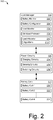
- Fig. 2 illustrates an example battery system 200 capable of implementing aspects of the techniques described herein.
- battery system 200 includes load manager 118, power circuitry 120, and battery cells 122.
- load manager 118 is implemented in software (e.g., application programming interface) or firmware of a computing device by a processor executing processor-executable instructions.
- components of load manager 118 can be implemented integral with other components of battery system 200, such as power circuitry 120 and battery cells 122 (individual or packaged).
- Load manager 118 may include any or all of the entities shown in Fig. 2 , which include battery monitor 202, battery configurator 204, load monitor 206, workload estimator 208, and load allocator 210.
- Battery monitor 202 is configured to monitor characteristics of battery cells 122, such as terminal voltage, current flow, state-of-charge (e.g., remaining capacity), temperature, age ( e.g., time or charging cycles), and the like. In some cases, battery monitor 202 may calculate or determine the internal resistance of a battery cell based on any of the other characteristics, such as age, temperature, or state-of-charge.
- Battery configurator 204 is configured to determine or access respective configuration information for battery cells 122, such as cell manufacturer, chemistry type, rated capacity, voltage and current limits (e.g., cutoffs), circuit topology, and the like. In some cases, the information of battery configurator 204 may also be useful in determining an internal resistance of a battery cell. Battery configurator 204 may store and enable other entities of load manager 118 to access this battery cell configuration information.
- Load monitor 206 monitors an amount of load power consumed by computing device 102 to operate.
- Load monitor 206 may monitor a current amount of load power (e.g., instantaneous power consumption) or load power consumed over time, such as by Coulomb counting.
- This load power is typically the amount of power provided by, or drawn from, one or more of battery cells 122 to enable operations of computing device 102.
- load monitor 206 monitors individual amounts of power drawn from each respective one of battery cells 122.
- Load monitor 206 may also monitor an amount of power applied to one or more of battery cells 122 by computing device 102 during charging.
- Workload estimator 208 estimates an amount of power that computing device 102 may consume when performing various tasks or operations. In some cases, the amount of power is estimated over duration of time, for a future duration of time, or at a future point in time. The estimation of the power may be based on tasks ( e.g., whether the screen is on (high power) or off (low power)) that computing device 102 is performing, scheduled to perform, likely to perform, and so on.
- tasks e.g., whether the screen is on (high power) or off (low power)
- workload estimator may receive information from operating system 114 that indicates a set of tasks are scheduled for execution by resources of computing device 102. Based on the set of tasks, workload estimator 208 estimates or forecasts an expected amount of current that computing device 102 will consume to perform the tasks. In some cases, workload estimator 208 provides a power consumption forecast over time based on a schedule ( e.g., waking or sleep times) or predicted order of execution for the tasks.
- a schedule e.g., waking or sleep times
- Load allocator 210 is configured to determine allocations of computing device 102's load power to be served by battery cells 122. This allocation may define respective portions of the device's load power (e.g., total required operational power) that are distributed to each of battery cells 122. The device draws its required load power according to this distribution from the different battery cells; i.e., each battery cell serves its respective portion of the device's load power. In some cases, load allocator 210 determines a load allocation scheme based on information received from other entities of load manager 118, such as current and expected workloads of computing device 102, and respective characteristics ( e.g., internal resistances) of battery cells 122. Based on this information, an allocation scheme may be configured to draw power from all or a subset of battery cells 122 to maximize an efficiency at which power is drawn from battery cells 122.
- load allocator 210 determines a load allocation scheme based on information received from other entities of load manager 118, such as current and expected workloads of computing device 102
- the efficiency at which power is drawn from battery cells 122 can be defined as a ratio of useful energy extracted from battery cells 122 to the total energy stored by battery cells 122. Ideally, all of the stored energy would be extracted from battery cells 122 as useful energy for consumption by computing device 102. At least some of the stored energy, however, is wasted or lost within battery cells 122 due to various factors, such as parasitic losses, temperature, or material breakdown. Accordingly, minimizing the wasted energy in each of battery cells 122 can be effective to maximize an overall efficiency at which power is drawn from all of battery cells 122.
- the internal resistance of the battery may also affect the amount of wasted energy under a given current level flowing through the battery. Quantitatively, simplifying the battery to an equivalent circuit of internal resistance and an ideal power source, the wasted energy can be modeled as the square of the current multiplied by the internal resistance over time. Thus, higher internal resistances cause greater amounts of wasted energy within the battery. Under fixed external circumstances, the internal resistance in turn depends on the battery's state-of-charge (SoC), the decrease of which causes an increase in the internal resistance. As such, when the battery's SoC decreases, more energy is wasted under a given load power level as the battery's internal resistance increases. Accordingly, load allocator 210 may consider a load power level or respective internal resistances of batteries when allocating workloads of computing device 102.
- SoC state-of-charge
- Load allocator 210 may also allocate the load power of computing device 102 based on load algorithms 212 (algorithms 212).
- Algorithms 212 may include general classes of allocation algorithms, such as scheduling algorithms and weighted algorithms. Scheduling algorithms include algorithms by which load power of computing device 102 is served, at any time, by one or multiple batteries. Alternately, weighted algorithms include algorithms by which load power of computing device 102 is served by all or a subset of multiple batteries. Either class of algorithm may provide a more-efficient allocation of the load power depending on a device workload or characteristics of the multiple batteries providing device power.
- scheduling algorithms include a sequential algorithm, least-internal-resistance algorithm (least-resistance algorithms), and threshold algorithm.
- the sequential algorithms allocate load power such that the load power is drawn sequentially from one battery after another. For example, one battery may be used until discharged completely, at which point power is drawn from a next battery.
- the least-resistance algorithm which also may be referred to as a 'greedy' algorithm, allocates load power based on the instantaneous power level of a load and the instantaneous respective internal resistances of the batteries. Because drawing large amounts of power from batteries having high internal resistances is highly inefficient, the least-resistance algorithm allocates high power loads to the batteries that have the least internal resistance. Additionally, the least-resistance algorithm may allocate low power loads to batteries with higher internal resistances.
- the threshold algorithm operates based on particular thresholds associated with batteries, such as thresholds for SoC or internal resistance. More specifically, the threshold algorithm may be implemented as a hybrid algorithm that implements aspects other algorithms based on thresholds. For example, a threshold algorithm may apply a sequential algorithm to multiple batteries until each battery reaches a particular threshold, such as 50% of state-of-charge. The threshold algorithm can then apply the least-resistance algorithm to allocate device load power to the partially discharged multiple batteries.
- Weighted algorithms may include a parallel algorithm and variable-weight algorithm. These algorithms allocate load power or workload of computing device 102 to multiple batteries concurrently.
- the parallel algorithm allocates the load power to all of the multiple batteries, and may be implemented by connecting the batteries together in parallel. In most cases, however, parallel connection of the batteries limits application of the parallel algorithm to similar type batteries to prevent unintended inter-battery current flow ( e.g., charging), which can damage the batteries.
- Equation 3 is the result of the connecting multiple batteries in parallel to minimize instantaneous energy loss associated with resistances R i .
- the application of the parallel algorithm may be best suited for homogenous batteries to avoid unbalanced battery circuits or unintended charging between batteries of different states.
- the variable-weight algorithm may allocate varying portions of load power to multiple batteries other than those subject to Equation 3. In some cases, the variable-weight algorithm is capable of allocating different amounts of load power to each of the multiple batteries. Because the variable-weight algorithm is capable of allocating specific load power to individual or subsets of multiple batteries, the load power can be drawn from heterogeneous batteries. Alternately or additionally, the variable-weight algorithm may allocate approximately equal portions of load power to heterogeneous batteries, such as by accounting for differences between the batteries.
- variable-weight algorithm provides an optimal efficiency over time, particularly when workloads vary between low-power and high-power. In some cases, this includes allocating low-power loads into batteries having lower SoCs (higher internal resistance) to preserve efficiencies of other batteries having higher SoCs (lower internal resistances).
- R ′ i V for any i
- y i * H ⁇ z i ⁇ j z j .
- max z ⁇ z i , s . t . ⁇ 1 ⁇ i z i C
- variable-weight algorithm may consider the derivative of a battery's internal resistance to achieve an optimal allocation of load power.
- the square-root distribution may not be achievable.
- charging between the multiple batteries may enable more-optimized workload allocations, such as when current intensities are negative.
- an optimal solution may include leveling out the internal resistances across the batteries, possibly by inter-battery recharging.
- load allocator 210 may implement any or all of the described aspects of load allocation in conjunction with any of the other algorithms described herein.
- any or all of battery monitor 202, battery configurator 204, load monitor 206, workload estimator 208, and load allocator 210 may be implemented separate from each other or combined or integrated in any suitable form.
- any of these entities, or functions thereof, may be combined generally as load manager 118, which can be implemented as a program application interface (API) or system component of operating system 114.
- API program application interface
- Battery system 200 also includes power circuitry 120, which provides an interface between load manager 118 and battery cells 122.
- power circuitry 120 may include hardware and firmware that enables computing device 102 to draw power from ( e.g., discharge), apply power to ( e.g., charge) battery cells 122, and implement various embodiments thereof.
- power circuitry 120 includes charging circuitry 214, sensing circuitry 216, and switching circuitry 218.
- Charging circuitry 214 is configured to provide current by which battery cells 122 are charged. Charging circuitry 214 may implement any suitable charging profile such as constant current, constant voltage, or custom profiles provided by load manager 118, such as intra-battery charging. In at least some embodiments, charging circuitry 214 is capable of providing different amounts of current to different respective battery cells being charged concurrently.
- Sensing circuitry 216 is configured to sense or monitor operational characteristics of battery cells 122. These operational characteristics may include a voltage level, an amount of current applied to, or an amount of current drawn from a respective one of battery cells 122. In some cases, sensing circuitry 216 may be implemented integral with charging circuitry 214, such as part of a charging controller or circuit that includes sensing elements (e.g., analog-to-digital converters (ADCs) and sense resistors).
- ADCs analog-to-digital converters
- Power circuitry 120 also includes switching circuitry 218, which enables load manager 118 to allocate and distribute load power of computing device 102 to battery cells 122. In some cases, portions of the load power are distributed to all or a subset of battery cells 122. In such cases, each portion of the distributed load power are different from each other.
- Switching circuitry 218 may be implemented using any suitable circuits, such as multiplexing circuitry that switches between battery cells 122 to facilitate connection with an appropriate set of power circuitry for battery cell sensing, power consumption, or power application ( e.g., charging).
- Battery cells 122 may include any suitable number or type of battery cells.
- battery cells 122 include battery cell-1 220, battery cell-2 222, and battery cell-N 224, where N may be any suitable integer.
- Battery cells 122 may include various homogeneous or heterogeneous combinations of cell shape, capacity, or chemistry type.
- Each of battery cells 122 may have a particular or different cell configuration, such as a chemistry type, shape, capacity, packaging, electrode size or shape, series or parallel cell arrangement, and the like. Accordingly, each of battery cells 122 may also have different parameters, such as internal resistance, capacitance, or concentration resistance.
- FIG. 300 Illustrates an example battery configuration 300 in accordance with one or more embodiments.
- Battery configuration 300 includes battery-1 302, battery-2 304, battery-3 306, and battery-4 308, each of which may be configured as any suitable type of battery. Additionally, each of batteries 302 through 308 is configured with a respective parallel bulk capacitance 310 through 316 ( e.g., super capacitor), which can be effective to mitigate a respective spike of current load on a given battery.
- a respective parallel bulk capacitance 310 through 316 e.g., super capacitor
- Each of batteries 302 through 308 provide power to or receive power from computing device 102. This power may be distributed as respective portions of current, which are shown as current I 1 318, current I 2 320, current I 3 322, and current I 4 324. These individual currents are multiplexed via battery switching circuit 326 (switching circuit 326), the summation of which is current I Device 328.
- switching circuit 326 is but one example implementation of sensing circuitry 216 as described with respect to Fig. 2 .
- battery switching circuit 326 switches rapidly between batteries 302 through 308 effective to draw current or power from each of them.
- battery switching circuit 326 may isolate one of batteries 302 through 306 and switch between a subset of the remaining batteries to continue powering computing device 102.
- battery configuration 300 may be implemented any suitable topology, such as multiple serial by multiple parallel topologies (e.g., 2S3P, 3S4P, or 2S2P).
- each serial level of battery configuration 300 may include an instance of switching circuit 326. This may enable power to be drawn from different combinations of serial batteries at a desired voltage.
- Fig. 3 also illustrates example battery model 330, which may be used to model any of the batteries or battery cells described herein.
- battery model 330 can be used by load allocator 210 to calculate or determine an efficiency at which the battery cell or battery is capable of providing power.
- parameters that affect a batteries efficiency are dynamic and may not be directly observable or measurable by traditional sensing techniques. In such cases, battery model 330 may be useful in estimating these parameters or their effects on an efficiency of the battery.
- battery model 330 includes an ideal voltage source that provides power and has an open circuit voltage 332 (Vo 332).
- Battery model 330 also includes direct current (DC) internal resistance 334 (R DCIR 334), which causes internal power loss as battery current 336 (I 336) passes through the battery.
- R DCIR 334 may be determined based on a SoC for battery model 330.
- Battery voltage 338 (V 338) represents the terminal voltage for battery model 330 and can be effected by the losses associated with the other parameters, such as when current passes through internal resistance 334 ( e.g., voltage drop associated therewith).
- the methods described herein may be used separately or in combination with each other, in whole or in part. These methods are shown as sets of operations (or acts) performed, such as through one or more entities or modules, and are not necessarily limited to the order shown for performing the operation.
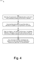
- Fig. 4 depicts method 400 for estimating an internal resistance of a battery cell, including operations performed by load manager 118 or load allocator 210.
- an amount of load power being consumed by a multi-battery device is determined.
- the multiple batteries of the device may include any suitable number or combination of batteries, such as batteries of different capacities or chemistry types.
- the amount of load power being consumed may be measured by a battery monitor. In other cases, the amount of power being consumed may be estimated.
- respective efficiencies at which multiple batteries are capable of providing power the device are determined. These efficiencies may indicate an amount of energy that will be wasted when various amounts of power are drawn from each of the batteries. In some cases, the efficiencies are determined based on a configuration or characteristic of each battery, such as chemistry type, capacity, SoC, internal resistance, age, temperature, and the like.
- battery cells 122 of smart phone 104 include a lithium polymer cell and a lithium ceramic cell.
- load allocator 210 receives information from battery monitor 202 and battery configurator 204. This information indicates that the lithium polymer cell's SoC is about 25% of a 1.9 Ahr capacity and the lithium ceramic cell's SoC is about 50% of a 210 mAhr capacity. From this information, load allocator 210 determines an internal resistance for the lithium polymer and lithium ceramic cells of 200 mOhms and 1 Ohm, respectively.
- an allocation of the load power is determined based on the respective efficiencies of the multiple batteries. This can be effective to maximize an efficiency at which the multiple batteries power the device. In some cases, the allocation is determined based on respective internal resistances of the multiple batteries and the amount of load power being consumed by the device. The determined allocation may allocate different amount of the load power to a subset or all of the multiple batteries. Alternately or additionally, some of the multiple batteries may not receive an allocation of the load power ( e.g., a portion of zero load power).
- load allocator 210 determines an allocation for smart phone 104's load power of approximately 3 W. Based on the internal resistances of the lithium polymer and lithium ceramic cells, load allocator determines that a weighted allocation of the load power will most efficiently utilize the remaining energy of the batteries. Here, assume that this allocation is approximately 500 mW of load power to the lithium ceramic cell and approximately 2500 mW of load power to the lithium polymer cell.
- a respective portion of the load power is drawn from each of the multiple batteries based on the determined allocation. This may be effective to distribute the respective portions to a subset or all of the multiple batteries. In some cases, the respective portions are distributed to each of the multiple batteries by switching circuitry. In such cases, the switching circuitry may switch between the multiple cells effective to draw the portions of load power concurrently. As noted above, the respective portions of load power may differ from each other, and some may be approximately zero ( e.g., batteries not being used).
- load allocator 210 distributes the load power of smart phone 104 to battery cells 122 via switching circuitry 218 in accordance with the determined weighted allocation. Returning to Fig. 5 , this is shown at 504, which indicates the load power drawn from the lithium polymer cell and at 506, which indicates the load power drawn from the lithium ceramic cell.
- load power 504 and 506 provide load power 502 by which smart phone 104 operates.
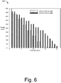
- energy profile 600 of Fig. 6 illustrates the distribution of smart phone 104's energy consumption over time.
- energy provided by the lithium polymer cell is shown as graph elements 602 and the energy provided by the lithium ceramic cell is shown as graph elements 604.
- the lithium ceramic cell provides energy until it reaches an end-of-discharge at approximate minute 14, at which point energy is provided solely by the lithium polymer cell. Because an efficiency at which energy is drawn from both batteries, the lifetime of smart phone 104 extends to 20 minutes, whereas under different battery usage patterns, the lifetime would be less.
- Fig. 7 depicts method 700 for allocating load power to multiple batteries over time, including operations performed by load manager 118 or load allocator 210.
- a current amount of load power being consumed by a multi-battery device is determined.
- the current amount of power being consumed may be classified as a high-power or low-power workload.
- the current amount of power may be calculated based on respective voltages of multiple batteries of the device and an amount of current being consumed. Alternately or additionally, indications of power consumption are received from power management circuitry of the device or the multiple batteries.
- Load monitor 206 determines that the current amount of power being consumed from battery cells 122 is approximately 5 W, which load allocator classifies as a high-power workload.
- Example classifications of workloads are illustrated by power graph 800 of Fig. 8 , in which workload are classified as high-power 802 and low-power 804. In this particular example, the current amount of power consumed by tablet computing device 106 is classified as a high-power workload 806.
- an expected amount of power that the device will consume at a future point in time is estimated.
- the expected amount of power may be estimated based on tasks or operations of the device that are scheduled for execution at the future point in time. As with the current amount of power, the expected amounts of power may also be classified as low-power or high-power workloads. In some cases, times at which the tasks or operations of the device are executed may be determined based on historical device use, daily activities of a user, or calendar information ( e.g., workday, appointment, and meeting information).
- workload estimator 208 forecasts power usage of table computing device 106 for the next several hours. To do so, workload estimator 208 queries a scheduler of operating system 114 and calendar to determine when activity levels of tablet computing device 106 are expected to change. Durations of time that correspond with these activity levels are then classified as low-power or high-power workloads, such as those shown in Fig. 8 . Note, that workloads are not necessarily scheduled for uniform durations of time, but can be estimated for activity levels or thresholds for high and low levels of power consumption. Low-power workload 808 is an example of one such workload during which device activity is low while the user sleeps.
- information concerning an efficiency at which each of the multiple batteries is capable of providing power is received.
- the information is received from an entity of the device monitoring the multiple batteries.
- a microcontroller within one of multiple batteries may transmit the information to the device.
- the information may include characteristics of a respective battery, such as the battery's SoC, internal resistance, age, temperature, remaining capacity, and the like.
- load allocator 210 receives SoC information from each of battery cells 122.
- an allocation of the load power is determined based on the current and expected amounts of power and the efficiencies of the multiple batteries. This can be effective to maximize an efficiency at which the multiple batteries power the device.
- the allocation is determined via an algorithm that analyzes the efficiency information associated with the multiple batteries. In such cases, these algorithms may include the sequential or parallel algorithms described herein, or combinations thereof.
- load allocator 210 analyzes the current workload and forecast workloads for tablet computing device 106 using the weighted algorithm. Due to the current high-power workload, load allocator 210 determines an allocation that spreads power consumption to all of battery cells 122 to minimize losses caused by their respective internal resistances.
- a portion of the current load power is drawn from each of the multiple batteries based on the determined allocation. This may be effective to distribute the portions of the current load power to a subset or all of the multiple batteries. In some cases, the respective portions are distributed to each of the multiple batteries by switching circuitry. In such cases, the switching circuitry may switch between the multiple cells effective to draw the portions of load power concurrently.
- load allocator 210 distributes the load power of laptop computing device 106 to battery cells 122 via switching circuitry 218 in accordance with the determined allocation.
- the allocation is determined using the weighted algorithm, other algorithms may also improve device runtimes of a device. For illustrative purposes, example runtimes are shown in Table 2 for a device having a lithium polymer cell and a lithium ceramic cell.
- method 700 may return to operation 702 to select another allocation using a same or different algorithm. This may occur when a workload of tablet computing device 106 transitions between high-power and low-power workloads, such as at low-power workload 808.
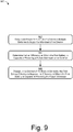
- Fig. 9 depicts method 900 for recharging across multiple batteries of a device, including operations performed by load manager 118 or load allocator 210.
- load power is drawn from a first battery of a device having multiple batteries.
- the multiple batteries of the device may include any suitable number of batteries of various configurations or states.
- the load power is drawn in accordance with an allocation determined by a scheduling algorithm.
- the scheduling algorithm may allocate the first battery's power to serve a current workload of the device.
- the current workload of the device may be a low-power workload, such as a predicted sleep or standby time for the device.
- an efficiency at which the first battery is capable of powering a future workload is not optimal.
- the determination is responsive to changes in the future workload's estimated power consumption.
- a workload estimator may forecast or re-estimate a future workload of the device as a high-power workload. For example, the workload estimator may re-estimate a series of workloads in response to unexpected user interaction.
- a scheduling algorithm may determine that, of the multiple batteries, the future high-power workload would be more-efficiently served by the first battery. Due to previous discharge, however, an efficiency at which the first battery can serve the high-power workload may not be optimal.
- the first battery is charged from a second battery of the device to increase the first battery's state-of-charge.
- the first battery is charged from all or a subset of the multiple batteries. This can be effective to improve the efficiency at which the first battery is capable of powering the future high-power workload.
- increasing the first battery's state-of-charge may decrease the first battery's internal resistance. By so doing, internal losses of the first battery are reduced while future workload is served.
- aspects of these methods may be implemented in hardware (e.g., fixed logic circuitry), firmware, a System-on-Chip (SoC), software, manual processing, or any combination thereof.
- a software implementation represents program code that performs specified tasks when executed by a computer processor, such as software, applications, routines, programs, objects, components, data structures, procedures, modules, functions, and the like.
- the program code can be stored in one or more computer-readable memory devices, both local and/or remote to a computer processor.
- the methods may also be practiced in a distributed computing environment by multiple computing devices.
- Fig. 10 illustrates various components of example device 1000 that can be implemented as any type of mobile, electronic, and/or computing device as described with reference to the previous Figs. 1-9 to implement techniques of load allocation for multi-battery devices.
- device 1000 can be implemented as one or a combination of a wired and/or wireless device, as a form of television client device (e.g., television set-top box, digital video recorder (DVR), etc.), consumer device, computer device, server device, portable computer device, user device, IoT device, communication device, video processing and/or rendering device, appliance device, gaming device, electronic device, and/or as another type of device.
- Device 1000 may also be associated with a user (e.g., a person) and/or an entity that operates the device such that a device describes logical devices that include users, software, firmware, and/or a combination of devices.
- Device 1000 includes communication modules 1002 that enable wired and/or wireless communication of device data 1004 (e.g., received data, data that is being received, data scheduled for broadcast, data packets of the data, etc.).
- Device data 1004 or other device content can include configuration settings of the device, media content stored on the device, and/or information associated with a user of the device.
- Media content stored on device 1000 can include any type of audio, video, and/or image data.
- Device 1000 includes one or more data inputs 1006 via which any type of data, media content, and/or inputs can be received, such as user-selectable inputs, messages, music, television media content, recorded video content, and any other type of audio, video, and/or image data received from any content and/or data source.
- Device 1000 also includes communication interfaces 1008, which can be implemented as any one or more of a serial and/or parallel interface, a wireless interface, any type of network interface, a modem, and as any other type of communication interface.
- Communication interfaces 1008 provide a connection and/or communication links between device 1000 and a communication network by which other electronic, computing, and communication devices communicate data with device 1000.
- Device 1000 includes one or more processors 1010 (e.g., any of microprocessors, controllers, and the like), which process various computer-executable instructions to control the operation of device 1000 and to enable techniques enabling load allocation in multi-battery devices.
- processors 1010 e.g., any of microprocessors, controllers, and the like
- device 1000 can be implemented with any one or combination of hardware, firmware, or fixed logic circuitry that is implemented in connection with processing and control circuits which are generally identified at 1012.
- device 1000 can include a system bus or data transfer system that couples the various components within the device.
- a system bus can include any one or combination of different bus structures, such as a memory bus or memory controller, a peripheral bus, a universal serial bus, and/or a processor or local bus that utilizes any of a variety of bus architectures.
- Device 1000 may be configured to operate from any suitable power source, such as battery cells 122, power circuitry 120, various external power sources (e.g., alternating-current (AC) power
- Device 1000 also includes computer-readable storage media 1014, such as one or more memory devices that enable persistent and/or non-transitory data storage (i.e., in contrast to mere signal transmission), examples of which include random access memory (RAM), non-volatile memory (e.g., any one or more of a read-only memory (ROM), flash memory, EPROM, EEPROM, etc.), and a disk storage device.
- RAM random access memory
- non-volatile memory e.g., any one or more of a read-only memory (ROM), flash memory, EPROM, EEPROM, etc.
- a disk storage device may be implemented as any type of magnetic or optical storage device, such as a hard disk drive, a recordable and/or rewriteable compact disc (CD), any type of a digital versatile disc (DVD), and the like.
- Device 1000 can also include a mass storage media device 1016.
- Computer-readable storage media 1014 provides data storage mechanisms to store device data 1004, as well as various device applications 1018 and any other types of information and/or data related to operational aspects of device 1000.
- an operating system 1020 can be maintained as a computer application with the computer-readable storage media 1014 and executed on processors 1010.
- Device applications 1018 may include a device manager, such as any form of a control application, software application, signal-processing and control module, code that is native to a particular device, a hardware abstraction layer for a particular device, and so on.
- Device applications 1018 also include any system components or modules to implement the techniques, such as load manager 118, load allocator 210, and any combination of components thereof.
Landscapes
- Engineering & Computer Science (AREA)
- Power Engineering (AREA)
- General Chemical & Material Sciences (AREA)
- Chemical & Material Sciences (AREA)
- Chemical Kinetics & Catalysis (AREA)
- Electrochemistry (AREA)
- Manufacturing & Machinery (AREA)
- Theoretical Computer Science (AREA)
- Physics & Mathematics (AREA)
- General Engineering & Computer Science (AREA)
- General Physics & Mathematics (AREA)
- Secondary Cells (AREA)
- Charge And Discharge Circuits For Batteries Or The Like (AREA)
Claims (14)
- Procédé informatisé pour l'attribution de puissance de charge entre des batteries multiples d'un dispositif, le procédé comprenant :la détermination (402 ; 702), pour le dispositif ayant les batteries multiples (122 ; 220 à 224), d'une quantité de la puissance de charge consommée par le dispositif pour fonctionner ;la détermination (404 ; 706), pour au moins certaines des batteries multiples, d'une efficacité à laquelle la batterie est capable de générer de la puissance ;la détermination (406 ; 708), sur la base des efficacités respectives d'au moins certaines des batteries multiples, d'une attribution de la puissance de charge aux batteries multiples efficace pour maximiser une efficacité à laquelle les batteries multiples alimentent le dispositif ; etl'extraction (408 ; 710), à partir de chacune des batteries multiples et sur la base de l'attribution déterminée, d'une partie respective de la puissance de charge pour alimenter le dispositif.
- Procédé informatisé selon la revendication 1, dans lequel au moins deux des batteries multiples (122 ; 220 à 224) sont des batteries hétérogènes ayant différents types chimiques ou différentes capacités.
- Procédé informatisé selon la revendication 1, dans lequel une première densité d'énergie d'une des batteries multiples (122 ; 220 à 224) est différente d'une seconde densité d'énergie d'une autre des batteries multiples efficace pour permettre à la batterie et à l'autre batterie de charger à des vitesses différentes.
- Procédé informatisé selon la revendication 1, dans lequel au moins deux des parties respectives de la puissance de charge sont différentes les unes des autres.
- Procédé informatisé selon la revendication 1, dans lequel les parties respectives de la puissance de charge sont consommées par le dispositif simultanément à partir des batteries multiples (122 ; 220 à 224).
- Procédé informatisé selon la revendication 1, dans lequel l'une des parties respectives de la puissance de charge extraite d'une des batteries multiples (122 ; 220 à 224) représente approximativement zéro Watt de la puissance de charge.
- Procédé informatisé selon la revendication 1, dans lequel l'extraction (408) des parties respectives de la puissance de charge comprend l'étape consistant à amener le circuit de commutation (218) à commuter entre les batteries multiples (122 ; 220 à 224) pour distribuer la consommation de la puissance de charge entre les batteries multiples.
- Procédé informatisé selon la revendication 1, dans lequel l'efficacité à laquelle la batterie (122 ; 220 à 224) est capable de générer de la puissance est déterminée sur la base d'un ou plusieurs des critères d'état de charge, de résistance interne, d'âge, de nombre de cycles, de température, de chimie, de topologie de circuit ou de capacité de la batterie.
- Système comprenant :des batteries multiples (122 ; 220 à 224) configurées pour générer de la puissance afin de permettre le fonctionnement du système ;un circuit de commutation (218) configuré pour permettre d'extraire la puissance de chacune des batteries multiples ;un circuit de détection (216) configuré pour mesurer la puissance de charge consommée par le système pour fonctionner ; etun gestionnaire de charge (118) configuré pour effectuer des opérations comprenant :la détermination (402; 702) d'une quantité de la puissance de charge consommée par le système ;la détermination (404; 706), pour chacune des batteries multiples, d'une efficacité respective à laquelle chacune des batteries multiples est en mesure de générer de la puissance ;la détermination (406 ; 708), sur la base des efficacités respectives des batteries multiples, d'une attribution de la puissance de charge aux batteries multiples efficace pour maximiser une efficacité à laquelle les batteries multiples alimentent le système ; etla distribution (408; 710), sur la base de l'attribution déterminée, de parties respectives de la puissance de charge à chacune des batteries multiples.
- Système selon la revendication 9, dans lequel les efficacités respectives pour chacune des batteries multiples (122 ; 220 à 224) sont déterminées sur la base de la quantité de la puissance de charge et d'un ou plusieurs des critères respectifs d'état de charge, de résistance interne, d'âge, de nombre de cycles, de température, de chimie, de topologie de circuit ou de capacité de la batterie.
- Système selon la revendication 9, dans lequel au moins deux des parties respectives de la puissance de charge distribuée sont différentes les unes des autres.
- Système selon la revendication 9, dans lequel les parties respectives de la puissance de charge distribuée sont extraites simultanément d'un sous-ensemble des batteries multiples (122 ; 220 à 224).
- Système selon la revendication 9, dans lequel les batteries multiples (122 ; 220 à 224) incluent au moins deux batteries hétérogènes ayant différents types chimiques ou différentes capacités.
- Système selon la revendication 9, dans lequel l'attribution est déterminée via un algorithme (212), l'algorithme incluant un algorithme parmi un algorithme à pondération variable, un algorithme séquentiel, un algorithme de la moindre résistance ou un algorithme de seuil.
Priority Applications (1)
| Application Number | Priority Date | Filing Date | Title |
|---|---|---|---|
| EP18203105.4A EP3462567A1 (fr) | 2015-02-26 | 2016-02-05 | Attribution de la charge pour des appareils à batterie multiples |
Applications Claiming Priority (2)
| Application Number | Priority Date | Filing Date | Title |
|---|---|---|---|
| US14/633,009 US9748765B2 (en) | 2015-02-26 | 2015-02-26 | Load allocation for multi-battery devices |
| PCT/US2016/016671 WO2016137715A1 (fr) | 2015-02-26 | 2016-02-05 | Affectation de charge pour dispositifs à multiples batteries |
Related Child Applications (2)
| Application Number | Title | Priority Date | Filing Date |
|---|---|---|---|
| EP18203105.4A Division-Into EP3462567A1 (fr) | 2015-02-26 | 2016-02-05 | Attribution de la charge pour des appareils à batterie multiples |
| EP18203105.4A Division EP3462567A1 (fr) | 2015-02-26 | 2016-02-05 | Attribution de la charge pour des appareils à batterie multiples |
Publications (2)
| Publication Number | Publication Date |
|---|---|
| EP3262734A1 EP3262734A1 (fr) | 2018-01-03 |
| EP3262734B1 true EP3262734B1 (fr) | 2018-12-05 |
Family
ID=55410257
Family Applications (2)
| Application Number | Title | Priority Date | Filing Date |
|---|---|---|---|
| EP16706100.1A Active EP3262734B1 (fr) | 2015-02-26 | 2016-02-05 | Attribution de la charge pour des appareils à batterie multiples |
| EP18203105.4A Withdrawn EP3462567A1 (fr) | 2015-02-26 | 2016-02-05 | Attribution de la charge pour des appareils à batterie multiples |
Family Applications After (1)
| Application Number | Title | Priority Date | Filing Date |
|---|---|---|---|
| EP18203105.4A Withdrawn EP3462567A1 (fr) | 2015-02-26 | 2016-02-05 | Attribution de la charge pour des appareils à batterie multiples |
Country Status (5)
| Country | Link |
|---|---|
| US (2) | US9748765B2 (fr) |
| EP (2) | EP3262734B1 (fr) |
| CN (1) | CN107408824B (fr) |
| TW (1) | TW201644143A (fr) |
| WO (1) | WO2016137715A1 (fr) |
Cited By (1)
| Publication number | Priority date | Publication date | Assignee | Title |
|---|---|---|---|---|
| EP4060784A1 (fr) | 2021-03-17 | 2022-09-21 | ETH Zurich | Procédé de gestion de puissance pour de multiples systèmes de source de puissance |
Families Citing this family (23)
| Publication number | Priority date | Publication date | Assignee | Title |
|---|---|---|---|---|
| US9696782B2 (en) | 2015-02-09 | 2017-07-04 | Microsoft Technology Licensing, Llc | Battery parameter-based power management for suppressing power spikes |
| US10158148B2 (en) | 2015-02-18 | 2018-12-18 | Microsoft Technology Licensing, Llc | Dynamically changing internal state of a battery |
| US9748765B2 (en) | 2015-02-26 | 2017-08-29 | Microsoft Technology Licensing, Llc | Load allocation for multi-battery devices |
| US9939862B2 (en) | 2015-11-13 | 2018-04-10 | Microsoft Technology Licensing, Llc | Latency-based energy storage device selection |
| US10061366B2 (en) | 2015-11-17 | 2018-08-28 | Microsoft Technology Licensing, Llc | Schedule-based energy storage device selection |
| US10224715B2 (en) * | 2015-11-24 | 2019-03-05 | The Johns Hopkins University | Intelligent power routing device |
| US9793570B2 (en) | 2015-12-04 | 2017-10-17 | Microsoft Technology Licensing, Llc | Shared electrode battery |
| DE102017201061A1 (de) * | 2017-01-24 | 2018-07-26 | Robert Bosch Gmbh | Verfahren zum Betreiben eines hybriden Energiespeichersystems |
| US10343552B2 (en) * | 2017-02-08 | 2019-07-09 | Samsung Electronics Co., Ltd. | Heterogeneous electrical energy storage system |
| CN108400623B (zh) * | 2017-02-08 | 2023-01-10 | 中兴通讯股份有限公司 | 一种终端及其实现多路径供电管理的方法 |
| EP3613123A4 (fr) * | 2017-04-21 | 2020-10-07 | Hewlett-Packard Development Company, L.P. | Configurations de batterie fondées sur le rendement |
| US10739742B2 (en) * | 2017-04-27 | 2020-08-11 | Johnson Controls Technology Company | Building energy system with stochastic model predictive control |
| TWI649939B (zh) | 2017-07-07 | 2019-02-01 | 財團法人工業技術研究院 | 電源裝置運作方法、電源裝置及電源裝置管理系統 |
| US10948546B2 (en) * | 2017-10-02 | 2021-03-16 | Semiconductor Components Industries, Llc | Methods and apparatus for battery management |
| CN108539231B (zh) * | 2018-03-20 | 2021-01-05 | 佛山(云浮)氢能产业与新材料发展研究院 | 一种多套燃料电池系统的协调控制方法及系统 |
| US10326305B1 (en) | 2018-08-27 | 2019-06-18 | Ekergy Llc | Personal power plant system and methods of inverse energy generation |
| US10615610B1 (en) | 2019-05-28 | 2020-04-07 | Ekergy Llc | System and method for efficient charging of multiple battery cassettes |
| EP4310520A3 (fr) * | 2019-07-04 | 2024-03-27 | Volvo Truck Corporation | Procédé de commande de connexion électrique de blocs-batteries |
| US10723235B1 (en) * | 2019-08-30 | 2020-07-28 | Kitty Hawk Corporation | Flexible battery system for a vehicle |
| US20210092127A1 (en) * | 2019-09-19 | 2021-03-25 | Microsoft Technology Licensing, Llc | Writing role-backed access control to chain |
| JP2021191095A (ja) * | 2020-05-29 | 2021-12-13 | 株式会社日立製作所 | 蓄電システム制御装置、蓄電システムおよびプログラム |
| US11984749B2 (en) | 2020-06-16 | 2024-05-14 | Apple Inc. | Battery charging control for electronic devices |
| US11089398B1 (en) | 2020-06-16 | 2021-08-10 | Apple Inc. | Battery charging control for wireless headphones |
Family Cites Families (290)
| Publication number | Priority date | Publication date | Assignee | Title |
|---|---|---|---|---|
| US4145669A (en) | 1977-02-10 | 1979-03-20 | Westinghouse Electric Corp. | Cathode electrode configuration for gas laser system |
| DE3721529A1 (de) | 1987-06-30 | 1989-01-12 | Christiansen Jens | Triggerung und isolation von pseudofunkenschaltern |
| JPH0410366A (ja) | 1990-04-25 | 1992-01-14 | Otsuka Chem Co Ltd | 加熱機構を有する二次電池 |
| US5523671A (en) | 1991-02-14 | 1996-06-04 | Dell Usa, L.P. | Charging system for battery powered devices |
| US5315228A (en) | 1992-01-24 | 1994-05-24 | Compaq Computer Corp. | Battery charge monitor and fuel gauge |
| US5440221A (en) | 1992-07-08 | 1995-08-08 | Benchmarg Microelectronics, Inc. | Method and apparatus for monitoring batttery capacity with charge control |
| JPH0684544A (ja) | 1992-09-01 | 1994-03-25 | Nippondenso Co Ltd | リチウム二次電池 |
| FR2702885B1 (fr) | 1993-03-15 | 1995-04-21 | Alcatel Converters | Système de contrôle de vieillissement d'une batterie et procédé mis en Óoeuvre dans un tel système. |
| JP3549540B2 (ja) | 1994-03-30 | 2004-08-04 | アルザ・コーポレーション | 電気的移送式投与中の皮膚刺激状態の軽減 |
| USRE38918E1 (en) | 1994-04-22 | 2005-12-13 | University Of Southern California | System and method for power-efficient charging and discharging of a capacitive load from a single source |
| US5705929A (en) | 1995-05-23 | 1998-01-06 | Fibercorp. Inc. | Battery capacity monitoring system |
| US5691742A (en) | 1995-05-24 | 1997-11-25 | Dell U.S.A., L.P. | Software battery gauge for portable computers |
| US5614332A (en) | 1995-05-26 | 1997-03-25 | Pavelle; Richard | Method and apparatus for increasing charging and discharging efficiency in batteries |
| US5684404A (en) | 1995-11-17 | 1997-11-04 | Sharp Microelectronics Technology, Inc. | System and method of measuring a battery lifetime |
| US5914585A (en) | 1996-02-20 | 1999-06-22 | Norand Corporation | Power sharing in computing systems with a plurality of electronic devices |
| JPH10136574A (ja) | 1996-10-31 | 1998-05-22 | Hitachi Ltd | バッテリ制御装置 |
| US5764032A (en) | 1997-03-06 | 1998-06-09 | Maxim Integrated Products, Inc. | Multiple battery switchover circuits |
| US5935724A (en) | 1997-04-04 | 1999-08-10 | Wilson Greatbatch Ltd. | Electrochemical cell having multiplate electrodes with differing discharge rate regions |
| US5818200A (en) | 1997-05-06 | 1998-10-06 | Dell U.S.A., L.P. | Dual smart battery detection system and method for portable computers |
| US6252511B1 (en) | 1997-06-20 | 2001-06-26 | Compaq Computer Corporation | Real-time battery gauge display |
| US7059769B1 (en) | 1997-06-27 | 2006-06-13 | Patrick Henry Potega | Apparatus for enabling multiple modes of operation among a plurality of devices |
| US5894212A (en) | 1997-09-19 | 1999-04-13 | Tarrytown Consulting, Inc. | Discharge monitoring and isolating system for batteries |
| SE519632C2 (sv) | 1997-12-23 | 2003-03-25 | Ericsson Telefon Ab L M | Portabel elektronisk apparat med tunnfilmsbatterier samt dessas användning i densamma |
| KR100255358B1 (ko) | 1997-12-27 | 2000-05-01 | 배문한 | 쌍극전지 |
| US6742003B2 (en) | 2001-04-30 | 2004-05-25 | Microsoft Corporation | Apparatus and accompanying methods for visualizing clusters of data and hierarchical cluster classifications |
| US6299998B1 (en) | 1999-03-15 | 2001-10-09 | Reveo, Inc. | Movable anode fuel cell battery |
| US6463495B1 (en) | 1999-03-29 | 2002-10-08 | Compaq Information Technologies Group, L.P. | Command and control infrastructure for a computer system using the computer's power rail |
| US6268711B1 (en) | 1999-05-05 | 2001-07-31 | Texas Instruments Incorporated | Battery manager |
| JP3323832B2 (ja) | 1999-06-08 | 2002-09-09 | インターナショナル・ビジネス・マシーンズ・コーポレーション | 複数の電池の充放電を制御する方法 |
| US6154012A (en) | 1999-10-13 | 2000-11-28 | Xicor, Inc. | Gas gauge implementation |
| JP2001211558A (ja) | 2000-01-27 | 2001-08-03 | Sanyo Electric Co Ltd | 複数の電池の充電方法 |
| JP3398703B2 (ja) | 2000-02-14 | 2003-04-21 | 米沢日本電気株式会社 | 放電回路及びデューティー比設定方法 |
| GB2360670B (en) | 2000-03-22 | 2004-02-04 | At & T Lab Cambridge Ltd | Power management system |
| JP3438135B2 (ja) | 2000-05-19 | 2003-08-18 | 富士通株式会社 | 情報機器及び省電力モード切替方法及び省電力モード切替プログラムを格納した記録媒体 |
| JP4759795B2 (ja) | 2000-09-28 | 2011-08-31 | 株式会社Gsユアサ | 二次電池の残存容量検知方法 |
| US6353304B1 (en) | 2001-01-19 | 2002-03-05 | Sandia Corporation | Optimal management of batteries in electric systems |
| US6771044B1 (en) | 2001-02-08 | 2004-08-03 | Frank A. Vinciguerra | Electrical power management for recharging multiple battery-powered computers |
| US6833792B1 (en) | 2001-03-30 | 2004-12-21 | Bellsouth Intellectual Property Corporation | Battery capacity indicator in a portable computing device |
| JP2005509244A (ja) | 2001-04-24 | 2005-04-07 | レベオ, インコーポレイティッド | ハイブリッド型電気化学セルシステム |
| US6417646B1 (en) | 2001-05-22 | 2002-07-09 | Honeywell International Inc. | Circuit for monitoring cells of a multi-cell battery during charge |
| US7174543B2 (en) | 2001-08-29 | 2007-02-06 | Analog Devices, Inc. | High-speed program tracing |
| JP2003111284A (ja) | 2001-09-27 | 2003-04-11 | Nec Mobile Energy Kk | 省電力化電池パック |
| JP2003194897A (ja) | 2001-12-26 | 2003-07-09 | Sanyo Electric Co Ltd | 電池の残容量演算方法とパック電池 |
| US6977479B2 (en) | 2002-01-08 | 2005-12-20 | Hsu Po-Jung John | Portable cell phone battery charger using solar energy as the primary source of power |
| KR100446510B1 (ko) | 2002-02-04 | 2004-09-04 | 삼성전자주식회사 | 휴대용 전자단말의 전원 관리 방법 |
| US8036718B2 (en) | 2002-06-17 | 2011-10-11 | Nokia Corporation | Power management profile on a mobile device |
| US7065659B2 (en) | 2002-06-28 | 2006-06-20 | Microsoft Corporation | Power management architecture for defining component power states under a global power state and maintaining a power state floor for a specified component if a power state for the specified component under a new global power state is below the power state floor |
| US6992580B2 (en) | 2002-07-25 | 2006-01-31 | Motorola, Inc. | Portable communication device and corresponding method of operation |
| US6710578B1 (en) | 2002-08-27 | 2004-03-23 | Motorola, Inc. | Power resource management in a portable communication device |
| US6650089B1 (en) | 2002-10-16 | 2003-11-18 | Texas Instruments Incorporated | Control circuit for multiple battery systems with capacity gauge on end equipment |
| US7259538B2 (en) | 2002-11-14 | 2007-08-21 | Hewlett-Packard Development Company, L.P. | Adaptive battery conditioning employing battery chemistry determination |
| JP3669702B2 (ja) | 2003-02-25 | 2005-07-13 | 松下電器産業株式会社 | アプリケーションプログラムの予測方法及び移動体端末 |
| US7734317B2 (en) | 2003-03-18 | 2010-06-08 | Qualcomm Incorporated | Battery management |
| US7015596B2 (en) | 2003-07-03 | 2006-03-21 | Opher Pail | Electronic device display system and method |
| US6847191B1 (en) | 2003-08-13 | 2005-01-25 | Kinpo Electronics, Inc. | Power control device and the operating method thereof |
| US7020500B2 (en) | 2003-12-16 | 2006-03-28 | Michael Gabriel Saghbini | Mobile communication system powered by multiple batteries |
| JP4304600B2 (ja) | 2004-01-19 | 2009-07-29 | 株式会社デンソー | 車両用フライングキャパシタ式電池電圧検出装置 |
| US7339353B1 (en) | 2004-03-10 | 2008-03-04 | Quallion Llc | Power system for managing power from multiple power sources |
| US7475267B1 (en) | 2004-03-31 | 2009-01-06 | Google, Inc. | Systems and methods for delay in startup of multiple components |
| US7339348B2 (en) | 2004-04-30 | 2008-03-04 | Dell Products L.P. | Battery pack including multiple battery cell technologies |
| JP4460946B2 (ja) | 2004-05-19 | 2010-05-12 | 株式会社東海理化電機製作所 | 作動制御装置 |
| GB2416631B (en) | 2004-07-23 | 2007-12-12 | Ford Motor Co | Energy management system and method |
| US7688033B2 (en) | 2004-09-29 | 2010-03-30 | Panasonic Ev Energy Co., Ltd. | Method for detecting state of secondary battery and device for detecting state of secondary battery |
| JP2006129588A (ja) | 2004-10-28 | 2006-05-18 | Sanyo Electric Co Ltd | 二次電池の電力制御方法及び電源装置 |
| US7570018B2 (en) | 2005-02-07 | 2009-08-04 | Colgate-Palmolive Co. | Rechargeable powered device |
| US7383451B2 (en) | 2005-02-18 | 2008-06-03 | Lenovo (Singapore) Pte. Ltd. | Controlling power usage of computing device components in holistic manner |
| US7176806B2 (en) | 2005-02-23 | 2007-02-13 | Eaglepicher Energy Products Corporation | Physical key to facilitate an inactive mode for a state-of-charge indicator within a battery |
| JP2008545962A (ja) | 2005-05-27 | 2008-12-18 | エルジー・ケム・リミテッド | バッテリーの内部抵抗を用いた最大出力推定方法及び装置 |
| US7541693B2 (en) | 2005-06-13 | 2009-06-02 | Intel Corporation | Power distribution network for computer systems and other low-power applications |
| US7529948B2 (en) | 2005-08-25 | 2009-05-05 | Apple Inc. | Methods and apparatuses for dynamic power estimation |
| US7430679B2 (en) | 2005-08-31 | 2008-09-30 | Apple Inc. | Charging of mobile devices |
| US7531989B2 (en) | 2005-11-02 | 2009-05-12 | 02Micro International Ltd. | Battery fuel gauge circuit |
| US7688029B2 (en) * | 2005-11-08 | 2010-03-30 | Eveready Battery Company, Inc. | Portable battery powered appliance and method of operation |
| JP5089883B2 (ja) | 2005-12-16 | 2012-12-05 | 日立ビークルエナジー株式会社 | 蓄電池管理装置 |
| US20070153371A1 (en) | 2005-12-30 | 2007-07-05 | Samsung Electronics Co., Ltd. | Display device, method of manufacturing the same, and composition for use in manufacturing the same |
| US7839121B2 (en) | 2006-03-20 | 2010-11-23 | Lg Electronics Inc. | Apparatus and method for managing power of battery packs in a portable device |
| KR101253635B1 (ko) | 2006-03-22 | 2013-04-10 | 엘지전자 주식회사 | 이동통신단말기 및 그를 이용한 배터리 스케줄링 방법 |
| US7583951B2 (en) | 2006-04-14 | 2009-09-01 | Sharp Laboratories Of America, Inc. | Virtual batteries for wireless communication device |
| US7814348B2 (en) | 2006-04-26 | 2010-10-12 | Adaptive Materials, Inc. | Power management apparatus |
| US8494479B2 (en) | 2006-04-27 | 2013-07-23 | Honeywell International Inc. | System and method for optimizing power supplies in a wireless transceiver |
| US7598702B2 (en) | 2006-04-27 | 2009-10-06 | Hewlett-Packard Development Company, L.P. | Power management system and method for controlling use of power-consuming applications |
| US7948208B2 (en) | 2006-06-01 | 2011-05-24 | Mojo Mobility, Inc. | Power source, charging system, and inductive receiver for mobile devices |
| TWI426678B (zh) | 2006-06-28 | 2014-02-11 | Boston Power Inc | 具有多重充電率之電子裝置、電池組、充電於電子裝置中的鋰離子電荷儲存電源供應器之方法及可攜式電腦 |
| US20080024007A1 (en) | 2006-07-10 | 2008-01-31 | Honeywell International Inc. | Multiple load hybrid power supply |
| US7415623B2 (en) | 2006-07-31 | 2008-08-19 | Motorola, Inc. | System for managing the power source life between multiple individually powered devices in a wired system and method of using same |
| US7716500B2 (en) | 2006-08-31 | 2010-05-11 | Ati Technologies Ulc | Power source dependent program execution |
| US7912288B2 (en) | 2006-09-21 | 2011-03-22 | Microsoft Corporation | Object detection and recognition system |
| DE102006046184B4 (de) | 2006-09-29 | 2009-01-02 | Infineon Technologies Ag | Verfahren, Vorrichtung und Computerprogrammprodukt zur Ermittlung einer voraussichtlichen Überschreitung einer maximal erlaubten Leistungsaufnahme eines mobilen elektronischen Geräts und mobiles elektronisches Gerät |
| US8001407B2 (en) | 2006-10-31 | 2011-08-16 | Hewlett-Packard Development Company, L.P. | Server configured for managing power and performance |
| KR100839385B1 (ko) | 2006-11-01 | 2008-06-19 | 삼성에스디아이 주식회사 | 배터리 관리 시스템 및 그의 구동 방법 |
| US8472699B2 (en) | 2006-11-22 | 2013-06-25 | Board Of Trustees Of The Leland Stanford Junior University | Arrangement and method for three-dimensional depth image construction |
| US8890480B2 (en) | 2006-11-30 | 2014-11-18 | The Boeing Company | Health management of rechargeable batteries |
| US8001400B2 (en) | 2006-12-01 | 2011-08-16 | Apple Inc. | Power consumption management for functional preservation in a battery-powered electronic device |
| US7787405B2 (en) | 2007-01-08 | 2010-08-31 | International Business Machines Corporation | Method for utilization of active power profiles used in prediction of power reserves for remote devices |
| EP1947729B1 (fr) | 2007-01-17 | 2010-09-22 | Samsung SDI Co., Ltd. | Batterie hybride |
| GB2446168A (en) | 2007-01-30 | 2008-08-06 | Third Sense Ltd | Reducing the power consumed from a battery |
| US7430675B2 (en) | 2007-02-16 | 2008-09-30 | Apple Inc. | Anticipatory power management for battery-powered electronic device |
| US20080218125A1 (en) | 2007-03-09 | 2008-09-11 | Ravi Prakash Bansal | Battery Charging System |
| JP2008232758A (ja) | 2007-03-19 | 2008-10-02 | Nippon Soken Inc | 二次電池の内部状態検出装置及びニューラルネット式状態量推定装置 |
| KR101389448B1 (ko) | 2007-03-27 | 2014-04-28 | 삼성전자주식회사 | 이동형 전자 장치 및 그것의 전원 관리 방법 |
| US20080263375A1 (en) | 2007-04-23 | 2008-10-23 | Sundstrom Robert J | Method And System For Managing Activities In A Battery Powered Device |
| WO2008133951A2 (fr) | 2007-04-24 | 2008-11-06 | Massachusetts Institute Of Technology | Procédé et appareil de traitement d'image |
| US8063606B2 (en) | 2007-05-11 | 2011-11-22 | Research In Motion Limited | Battery charger for a handheld computing device and an external battery |
| US20090007128A1 (en) | 2007-06-28 | 2009-01-01 | International Business Machines Corporation | method and system for orchestrating system resources with energy consumption monitoring |
| US8145918B2 (en) | 2007-06-28 | 2012-03-27 | International Business Machines Corporation | Monitoring system processes energy consumption |
| US20090016765A1 (en) | 2007-07-12 | 2009-01-15 | Kycera Mita Corporation | Image Forming Device and Image Forming Method |
| US8046180B2 (en) | 2007-07-13 | 2011-10-25 | Honeywell International Inc. | Model-based determination of power source replacement in wireless and other devices |
| EP2017938A1 (fr) | 2007-07-18 | 2009-01-21 | Magna Steyr Fahrzeugtechnik AG & Co. KG | Accumulateur |
| US20090085553A1 (en) | 2007-09-28 | 2009-04-02 | Pavan Kumar | Reconfigurable battery pack |
| US8097355B2 (en) | 2007-11-16 | 2012-01-17 | Microsoft Corporation | Protecting against incorrect battery polarity |
| KR20090064813A (ko) | 2007-12-17 | 2009-06-22 | 삼성전자주식회사 | 휴대용 단말기에서 백라이트의 동작시간을 동적으로변경하기 위한 방법 및 장치 |
| ITRM20080185A1 (it) | 2008-04-09 | 2009-10-10 | Michele Cunico | Autoveicolo |
| US8624560B2 (en) | 2008-04-11 | 2014-01-07 | Apple Inc. | Controlling battery charging based on current, voltage and temperature |
| JP5029488B2 (ja) | 2008-05-14 | 2012-09-19 | カシオ計算機株式会社 | 電子機器、電源制御方法及びプログラム |
| US8032317B2 (en) | 2008-05-15 | 2011-10-04 | The Nielsen Company (Us), Llc | System and methods for metering and analyzing energy consumption of events within a portable device |
| US8423306B2 (en) | 2008-05-22 | 2013-04-16 | Microsoft Corporation | Battery detection and user experience |
| US8242738B2 (en) | 2008-05-28 | 2012-08-14 | Texas Instruments Incorporated | Systems and methods for determining battery parameters following active operation of the battery |
| WO2010024892A1 (fr) | 2008-08-26 | 2010-03-04 | Reserve Power Cell, Llc | Mesures de l'état de charge de batteries par accumulation de données |
| US20100070334A1 (en) | 2008-09-08 | 2010-03-18 | Dante Monteverde | Method and system for location-based mobile device predictive services |
| JP5293020B2 (ja) | 2008-09-10 | 2013-09-18 | 住友化学株式会社 | 非水電解質二次電池用電極合剤、電極および非水電解質二次電池 |
| WO2010034079A1 (fr) | 2008-09-29 | 2010-04-01 | Wilson Lee | Système de charge de batteries à différents types d'éléments chimiques, et procédé d'identification et technique de charge améliorée de batteries primaires et secondaires à éléments secs |
| KR101538498B1 (ko) | 2008-10-07 | 2015-07-22 | 삼성전자주식회사 | 휴대용 단말기의 배터리 게이징 방법 및 장치 |
| US20100106994A1 (en) | 2008-10-27 | 2010-04-29 | David Carroll Challener | Method, apparatus, and system for adapting power consumption |
| US7944662B2 (en) | 2008-10-28 | 2011-05-17 | Steve Carkner | Multi-battery system for high voltage applications with proportional power sharing |
| US8386816B2 (en) | 2008-10-30 | 2013-02-26 | Nokia Corporation | Methods, apparatuses, and computer program products for reducing power consumption in computing devices |
| US20100123436A1 (en) | 2008-11-14 | 2010-05-20 | Symbol Technologies, Inc. | Optimized lithium-ion battery charging |
| CN201402987Y (zh) | 2008-12-31 | 2010-02-10 | 广州西格美信电子科技有限公司 | 具有电池管理系统的电池组 |
| US8250384B2 (en) | 2009-01-05 | 2012-08-21 | International Business Machines Corporation | Optimizer mechanism to increase battery length for mobile devices |
| WO2010091401A1 (fr) | 2009-02-09 | 2010-08-12 | Xtreme Power, Inc. | Décharge de batteries |
| US20100213897A1 (en) | 2009-02-23 | 2010-08-26 | Lawrence Tze-Leung Tse | Battery-Cell Converter Management Systems |
| US8369904B2 (en) | 2009-02-24 | 2013-02-05 | Gary Bennis | Cell phone battery system with back-up reserve |
| US8405332B1 (en) | 2009-02-24 | 2013-03-26 | Marvell International Ltd. | Method to eliminate current surge during spindle spin up |
| JP2012519469A (ja) | 2009-03-02 | 2012-08-23 | エレメント エナジー,インコーポレイティド | インテリジェントエネルギー蓄積パックを拡張可能に構成するシステム及び方法 |
| US10283974B2 (en) | 2009-03-02 | 2019-05-07 | Volterra Semiconductor LLC | Systems and methods for intelligent, adaptive management of energy storage packs |
| US8258748B2 (en) | 2009-03-11 | 2012-09-04 | Enfora, Inc. | Methods and apparatus for modeling, monitoring, simulating and controlling power consumption in battery-operated devices |
| JP5722875B2 (ja) | 2009-04-10 | 2015-05-27 | ザ リージェンツ オブ ザ ユニバーシティ オブ ミシガン | 大規模バッテリシステムのための動的に再構成可能な構造 |
| US8330420B2 (en) | 2009-04-10 | 2012-12-11 | The Regents Of The University Of Michigan | Dynamically reconfigurable framework for a large-scale battery system |
| DE102009002468A1 (de) | 2009-04-17 | 2010-10-21 | Robert Bosch Gmbh | Ermittlung des Innenwiderstands einer Batteriezelle einer Traktionsbatterie bei Einsatz von induktivem Zellbalancing |
| DE102009018787A1 (de) | 2009-04-24 | 2010-10-28 | Akasol Engineering Gmbh | Batteriemodul |
| US8313864B2 (en) | 2009-05-08 | 2012-11-20 | Robert Bosch Gmbh | Li-ion battery with blended electrode |
| US8190939B2 (en) | 2009-06-26 | 2012-05-29 | Microsoft Corporation | Reducing power consumption of computing devices by forecasting computing performance needs |
| US8898485B2 (en) | 2009-07-15 | 2014-11-25 | Microsoft Corporation | Power transfer between devices |
| US8754614B2 (en) | 2009-07-17 | 2014-06-17 | Tesla Motors, Inc. | Fast charging of battery using adjustable voltage control |
| GB2472051B (en) | 2009-07-22 | 2012-10-10 | Wolfson Microelectronics Plc | Power management apparatus and methods |
| US8922329B2 (en) | 2009-07-23 | 2014-12-30 | Qualcomm Incorporated | Battery charging to extend battery life and improve efficiency |
| WO2011014667A2 (fr) * | 2009-07-29 | 2011-02-03 | The Regents Of The University Of Michigan | Système pour planifier la charge et la décharge dune batterie |
| JP2011036052A (ja) | 2009-08-03 | 2011-02-17 | Sanyo Electric Co Ltd | 充電器 |
| TWI422849B (zh) | 2009-08-13 | 2014-01-11 | Neotec Semiconductor Ltd | 以直流內阻估算鋰電池容量之方法 |
| US8255716B2 (en) | 2009-08-27 | 2012-08-28 | Qualcomm Incorporated | Power optimization for data services |
| US9197081B2 (en) | 2009-08-28 | 2015-11-24 | The Charles Stark Draper Laboratory, Inc. | High-efficiency battery equalization for charging and discharging |
| US8744638B2 (en) | 2009-09-11 | 2014-06-03 | General Electric Company | Method and system for demand response in a distribution network |
| US8415926B2 (en) | 2009-10-19 | 2013-04-09 | Apple Inc. | In-situ battery health detector and end-of-life indicator |
| CN101714629A (zh) | 2009-11-10 | 2010-05-26 | 苏州大学 | 锂离子电池用三平台混合正极材料及其制备方法 |
| KR101064370B1 (ko) | 2009-11-17 | 2011-09-14 | 삼성모바일디스플레이주식회사 | 유기전계발광표시장치 및 그의 구동방법 |
| KR101613715B1 (ko) | 2009-12-12 | 2016-04-20 | 삼성전자 주식회사 | 컴퓨터 시스템 및 컴퓨터 시스템의 제어 방법 |
| WO2011087860A2 (fr) | 2009-12-22 | 2011-07-21 | G2 Llc | Systèmes de chargement et de gestion de batteries et procédés s'y rapportant |
| TW201122753A (en) | 2009-12-29 | 2011-07-01 | Ind Tech Res Inst | Voltage scaling systems |
| US8962188B2 (en) | 2010-01-07 | 2015-02-24 | Nanotek Instruments, Inc. | Anode compositions for lithium secondary batteries |
| US8504855B2 (en) | 2010-01-11 | 2013-08-06 | Qualcomm Incorporated | Domain specific language, compiler and JIT for dynamic power management |
| WO2011085327A2 (fr) | 2010-01-11 | 2011-07-14 | Amprius Inc. | Ensemble de cellules de capacité variable |
| US20110187309A1 (en) | 2010-02-01 | 2011-08-04 | Acoustic Arc International Ltd. | Apparatus for automatically switching and charging multiple batteries |
| TWI404963B (zh) | 2010-02-10 | 2013-08-11 | Chung Shan Inst Of Science | 電池模組檢測方法 |
| WO2011114247A1 (fr) | 2010-03-15 | 2011-09-22 | Brusa Elektronik Ag | Equilibrage des états de charge d'accumulateurs de charge |
| CN101834320B (zh) | 2010-04-07 | 2012-02-15 | 清华大学 | 电池调度方法和装置 |
| ES2673699T3 (es) | 2010-04-13 | 2018-06-25 | Fluidic, Inc. | Celda electroquímica de metal-aire con modo de alta eficiencia energética |
| US9130376B2 (en) | 2010-04-23 | 2015-09-08 | Psion Inc. | System and method for externally controlling the charging of a battery powered device |
| US8386826B2 (en) | 2010-04-23 | 2013-02-26 | Psion Inc. | System and method for managing power of a portable device |
| US9912175B2 (en) | 2010-04-23 | 2018-03-06 | 9609385 Canada Inc. | Battery harvester |
| US9413181B2 (en) | 2010-04-23 | 2016-08-09 | The Flewelling Ford Family Trust | Wearable power supply comprising a master cell and a slave cell |
| US8836274B2 (en) | 2010-04-26 | 2014-09-16 | Psion Inc. | System and method for displaying battery information before executing and operating system |
| US9726732B2 (en) | 2010-06-22 | 2017-08-08 | GM Global Technology Operations LLC | Adaptive battery parameter extraction and SOC estimation for lithium-ion battery |
| US8487473B2 (en) | 2010-06-24 | 2013-07-16 | Microsoft Corporation | Hierarchical power smoothing |
| JP5558941B2 (ja) | 2010-06-30 | 2014-07-23 | 三洋電機株式会社 | 電池の内部抵抗の検出方法 |
| US8732487B2 (en) | 2010-06-30 | 2014-05-20 | Microsoft Corporation | Predictive computing device power management |
| US8612077B2 (en) | 2010-07-07 | 2013-12-17 | Massachusetts Institute Of Technology | Hybrid electric vehicle and method of path dependent receding horizon control |
| US8423215B2 (en) | 2010-08-10 | 2013-04-16 | Tesla Motors, Inc. | Charge rate modulation of metal-air cells as a function of ambient oxygen concentration |
| US8843774B2 (en) * | 2010-08-20 | 2014-09-23 | Qualcomm Incorporated | Method and apparatus for managing battery power in response to an indication of an application being scheduled for immediate execution |
| KR20120025274A (ko) | 2010-09-07 | 2012-03-15 | 삼성전자주식회사 | 휴대단말의 컷오프 전원 제어 방법 및 장치 |
| US8478567B2 (en) * | 2010-09-28 | 2013-07-02 | Qualcomm Incorporated | Systems and methods for measuring the effectiveness of a workload predictor on a mobile device |
| US20120098705A1 (en) | 2010-10-22 | 2012-04-26 | Palm, Inc. | Use of heuristic data for sending message from mobile computing device |
| US8635630B2 (en) | 2010-10-25 | 2014-01-21 | Microsoft Corporation | Application lifetime management |
| US20120102407A1 (en) | 2010-10-25 | 2012-04-26 | Microsoft Corporation | Displaying battery life resulting from setting changes |
| US20120109519A1 (en) | 2010-10-27 | 2012-05-03 | Honda Motor Co., Ltd. | System and method for routing bev to charging station |
| US20120249052A1 (en) * | 2010-10-29 | 2012-10-04 | Sendyne Corporation | Charge redistribution method for cell arrays |
| US8569995B2 (en) | 2010-11-15 | 2013-10-29 | Volkswagen Ag | Control circuit and method for controlling a plurality of battery cells based on a determined number of coupled battery cells |
| US9182803B2 (en) | 2010-12-02 | 2015-11-10 | Advanced Micro Devices, Inc. | Load step mitigation method and apparatus |
| US20120144215A1 (en) | 2010-12-03 | 2012-06-07 | Advanced Micro Devices, Inc. | Maximum current limiting method and apparatus |
| US20120150247A1 (en) | 2010-12-08 | 2012-06-14 | Meier Giovanni C | Battery pack topology |
| EP2466718A1 (fr) | 2010-12-16 | 2012-06-20 | Dialog Semiconductor GmbH | Chargeur de plusieurs batteries avec ajustement automatique du courant de charge |
| US8665214B2 (en) | 2010-12-29 | 2014-03-04 | Qualcomm Incorporated | Extending battery life of a portable electronic device |
| US20120210150A1 (en) | 2011-02-10 | 2012-08-16 | Alcatel-Lucent Usa Inc. | Method And Apparatus Of Smart Power Management For Mobile Communication Terminals |
| FR2972304A1 (fr) | 2011-03-02 | 2012-09-07 | Commissariat Energie Atomique | Batterie avec gestion individuelle des cellules |
| US8949629B2 (en) | 2011-04-01 | 2015-02-03 | International Business Machines Corporation | Predicting battery power usage |
| GB201106356D0 (en) | 2011-04-14 | 2011-06-01 | Univ Strathclyde | Automated construction of usage policies |
| JP5208244B2 (ja) | 2011-05-06 | 2013-06-12 | 株式会社豊田自動織機 | リチウムイオン二次電池用負極活物質およびその製造方法、並びにリチウムイオン二次電池およびその製造方法 |
| JP5835941B2 (ja) | 2011-05-17 | 2015-12-24 | 日立オートモティブシステムズ株式会社 | 非水電解質二次電池 |
| US8624719B2 (en) | 2011-06-03 | 2014-01-07 | Bosch Automotive Service Solutions Llc | Smart phone control and notification for an electric vehicle charging station |
| US8751845B2 (en) | 2011-06-07 | 2014-06-10 | Microsoft Corporation | Estimating and preserving battery life based on usage patterns |
| US9152202B2 (en) | 2011-06-16 | 2015-10-06 | Microsoft Technology Licensing, Llc | Mobile device operations with battery optimization |
| US9136705B2 (en) | 2011-06-17 | 2015-09-15 | GM Global Technology Operations LLC | Scalable method of proportional active state of charge balancing for managing variations in the state of health of batteries |
| CN102230953B (zh) | 2011-06-20 | 2013-10-30 | 江南大学 | 蓄电池剩余容量及健康状况预测方法 |
| US9698451B2 (en) | 2011-07-06 | 2017-07-04 | Apple Inc. | Using reference electrodes to manage batteries for portable electronic devices |
| US8958854B1 (en) | 2011-07-22 | 2015-02-17 | Cellco Partnership | Dynamic battery saver for a mobile device |
| JP5623994B2 (ja) | 2011-07-29 | 2014-11-12 | 日立オートモティブシステムズ株式会社 | 電力変換装置 |
| CN103782443B (zh) | 2011-08-01 | 2017-10-03 | 马克西姆综合产品公司 | 用于混合电池的简单且高效的平衡电路以及方法 |
| CN103582963B (zh) | 2011-08-05 | 2015-12-23 | 松下知识产权经营株式会社 | 电子设备 |
| US20130043827A1 (en) | 2011-08-10 | 2013-02-21 | Nathan Daniel Weinstein | Portable power charger |
| US20130162430A1 (en) | 2011-08-18 | 2013-06-27 | Wefi, Inc. | Method and System for Charging Mobile Devices |
| US8538686B2 (en) | 2011-09-09 | 2013-09-17 | Microsoft Corporation | Transport-dependent prediction of destinations |
| WO2013052678A2 (fr) | 2011-10-04 | 2013-04-11 | Advanergy, Inc. | Système et procédé de gestion de batterie |
| US20130088900A1 (en) * | 2011-10-10 | 2013-04-11 | Jong-Ho Park | Energy storage system and controlling method of the same |
| US8766597B2 (en) | 2011-10-21 | 2014-07-01 | Linear Technology Corporation | Optimized bi-directional balancing method and system |
| WO2013060802A1 (fr) | 2011-10-25 | 2013-05-02 | St-Ericsson Sa | Dispositif électronique alimenté par batterie et procédé |
| US9166419B2 (en) | 2011-10-31 | 2015-10-20 | Robert Bosch Gmbh | Intelligent charging and discharging system for parallel configuration of series cells with semiconductor switching |
| US8829847B2 (en) | 2011-11-01 | 2014-09-09 | Blackberry Limited | Hybrid battery system for portable electronic devices |
| EP2590050B1 (fr) | 2011-11-01 | 2017-07-26 | BlackBerry Limited | Système de batterie hybride pour dispositifs électroniques portables |
| CN202424488U (zh) | 2011-11-18 | 2012-09-05 | 北京汇能精电科技有限公司 | 应用于光电池蓄电池共负极型的防反功能拓扑电路 |
| US8860347B2 (en) | 2011-11-29 | 2014-10-14 | Dispensing Dynamics International | Apparatus for reducing current drain and current spike impact on battery-powered electronic dispensers |
| US20130140902A1 (en) * | 2011-12-06 | 2013-06-06 | Research In Motion Limited | Fuel cell recovery time system |
| JP6224005B2 (ja) | 2012-01-19 | 2017-11-01 | ナイキ イノベイト シーブイ | 活動監視装置における電源管理 |
| US9262182B2 (en) | 2012-01-25 | 2016-02-16 | Apple Inc. | Dynamic parameter profiles for electronic devices |
| US8793520B2 (en) | 2012-01-25 | 2014-07-29 | Apple Inc. | Power management of electronic devices based on charging location |
| KR101498761B1 (ko) | 2012-02-02 | 2015-03-04 | 주식회사 엘지화학 | 배터리의 수명 예측 방법 및 장치, 이를 이용한 배터리 관리 시스템 |
| KR101178152B1 (ko) | 2012-02-23 | 2012-08-29 | 주식회사 엘지화학 | 신규한 구조의 전지팩 |
| US8594648B2 (en) | 2012-02-23 | 2013-11-26 | International Business Machines Corporation | Calendar-based power reserve |
| US9425631B2 (en) | 2012-02-27 | 2016-08-23 | Infineon Technologies Austria Ag | System and method for battery management |
| EP2669760A1 (fr) | 2012-03-28 | 2013-12-04 | Hitachi, Ltd. | Dispositif de connexion de batterie hétérogène et système de batterie utilisant celui-ci |
| US10690725B2 (en) | 2012-03-29 | 2020-06-23 | Atieva, Inc. | Battery state-of-charge estimation |
| KR102000295B1 (ko) | 2012-04-11 | 2019-10-01 | 유니버시티 오브 써던 캘리포니아 | 모바일 애플리케이션에 의해 요청된 서비스를 위한 가장 에너지 효율적인 방법의 실시간 선택 |
| US9698618B2 (en) | 2012-04-30 | 2017-07-04 | Hewlett-Packard Development Company, L.P. | Energy storage charging from an adjustable power source |
| BR112014027173A2 (pt) | 2012-05-04 | 2017-06-27 | Nano Now Pty Ltd | material de eletrodo, e eletrodo |
| JP6119402B2 (ja) | 2012-05-29 | 2017-04-26 | 株式会社Gsユアサ | 内部抵抗推定装置及び内部抵抗推定方法 |
| DE102012209660A1 (de) | 2012-06-08 | 2013-12-12 | Robert Bosch Gmbh | Batteriesystem und zugehöriges Verfahren zur Ermittlung des Innenwiderstandes von Batteriezellen oder Batteriemodulen des Batteriesystems |
| US9285851B2 (en) | 2012-06-22 | 2016-03-15 | Microsoft Technology Licensing, Llc | Optimizing battery use for known future load |
| EP2682840A1 (fr) | 2012-07-06 | 2014-01-08 | BlackBerry Limited | Contrôle du tirage de courant |
| JP5678928B2 (ja) | 2012-07-31 | 2015-03-04 | トヨタ自動車株式会社 | 全固体電池およびその製造方法 |
| US10110130B2 (en) | 2012-08-12 | 2018-10-23 | Loai Galal Bahgat Salem | Recursive DC-DC converter |
| US9318910B2 (en) | 2012-09-06 | 2016-04-19 | Samsung Sdi Co., Ltd. | Cell balancing circuit and cell balancing method using the same |
| US20140082384A1 (en) | 2012-09-20 | 2014-03-20 | Apple Inc. | Inferring user intent from battery usage level and charging trends |
| US8768567B2 (en) | 2012-10-29 | 2014-07-01 | Broadcom Corporation | Intelligent power and control policy for automotive applications |
| US9261563B2 (en) | 2012-11-07 | 2016-02-16 | Zero Motorcycles, Inc. | System and method for improved battery charge state determination |
| US9537994B2 (en) | 2012-12-03 | 2017-01-03 | Douglas Baldasare | System and method for providing and locating public or private mobile device charging stations |
| JP6045901B2 (ja) | 2012-12-18 | 2016-12-14 | オートモーティブエナジーサプライ株式会社 | 非水電解質電池用混合電極およびその製造方法 |
| US9189056B2 (en) | 2012-12-26 | 2015-11-17 | Intel Corporation | Mixed cell type battery module and uses thereof |
| US9012090B2 (en) | 2012-12-27 | 2015-04-21 | Palo Alto Research Center Incorporated | Advanced, high power and energy battery electrode manufactured by co-extrusion printing |
| US20140203780A1 (en) | 2013-01-24 | 2014-07-24 | Texas Instruments Incorporated | System and method for active charge and discharge current balancing in multiple parallel-connected battery packs |
| JP6157880B2 (ja) * | 2013-03-04 | 2017-07-05 | 株式会社東芝 | 複数電池を有する二次電池システム及び充放電電力等の配分方法 |
| US20140266061A1 (en) | 2013-03-13 | 2014-09-18 | Manitoba Hydro International Ltd. | Heterogeneous Energy Storage System and Associated Methods |
| US8972175B2 (en) | 2013-03-14 | 2015-03-03 | Qualcomm Incorporated | Navigation using crowdsourcing data |
| WO2014153034A1 (fr) | 2013-03-14 | 2014-09-25 | Milwaukee Electric Tool Corporation | Outil électrique possédant de multiples blocs-batteries |
| US9450274B2 (en) | 2013-03-15 | 2016-09-20 | Design Flux Technologies, Llc | Method and apparatus for creating a dynamically reconfigurable energy storage device |
| KR101459464B1 (ko) | 2013-03-19 | 2014-11-10 | 현대자동차 주식회사 | 연료전지 차량의 전력 제어 방법 및 시스템 |
| CN103226184B (zh) | 2013-03-20 | 2015-09-02 | 东莞宇龙通信科技有限公司 | 在多电池终端中获取电池信息的方法及多电池终端 |
| US9286568B2 (en) | 2013-05-03 | 2016-03-15 | Asurion, Llc | Battery drain analysis and prediction for wireless devices |
| US8749193B1 (en) | 2013-05-10 | 2014-06-10 | Inpower Llc | Battery protection circuit for multiple battery power supply and charging system |
| KR101595562B1 (ko) | 2013-05-30 | 2016-02-18 | 주식회사 엘지화학 | 리튬 이차전지 |
| US9194904B2 (en) | 2013-06-20 | 2015-11-24 | GM Global Technology Operations LLC | Systems and methods for detecting leakage paths in a battery sensing circuit |
| US9583279B2 (en) | 2013-07-01 | 2017-02-28 | Samsung Sdi Co., Ltd. | Secondary battery |
| US9671944B2 (en) | 2013-07-12 | 2017-06-06 | Microsoft Technology Licensing, Llc | Inclusion/exclusion user interface controls for range filters |
| JP6119516B2 (ja) | 2013-09-02 | 2017-04-26 | ソニー株式会社 | 組電池および電動車両 |
| JP2015064676A (ja) | 2013-09-24 | 2015-04-09 | 株式会社東芝 | 情報処理装置、半導体装置、情報処理方法およびプログラム |
| CN103683255A (zh) | 2013-11-28 | 2014-03-26 | 成都市宏山科技有限公司 | 开机防浪涌电路 |
| US10128528B2 (en) | 2014-01-02 | 2018-11-13 | Johnson Controls Technology Company | Combinatorial chemistries for matching multiple batteries |
| KR20150081731A (ko) | 2014-01-06 | 2015-07-15 | 삼성에스디아이 주식회사 | 배터리 팩, 배터리 팩을 포함하는 에너지 저장 시스템, 배터리 팩의 작동 방법 |
| US20150207344A1 (en) | 2014-01-17 | 2015-07-23 | General Electric Company | Configurable hybrid energy storage system and method |
| MX367686B (es) | 2014-02-12 | 2019-09-02 | Nantenergy Inc | Metodo para operar celdas electroquimicas que comprenden combustible electrodepositado. |
| US9760138B2 (en) * | 2014-04-25 | 2017-09-12 | Microsoft Technology Licensing, Llc | Load scheduling in multi-battery devices |
| US9475398B2 (en) | 2014-05-08 | 2016-10-25 | Cummins, Inc. | Optimization-based predictive method for battery charging |
| US10026998B2 (en) | 2014-05-15 | 2018-07-17 | Ford Global Technologies, Llc | Electric vehicle operation to manage battery capacity |
| US20150339415A1 (en) | 2014-05-21 | 2015-11-26 | Gary L. KLEIN | System and method for creating a simulation model via crowdsourcing |
| US9210662B1 (en) | 2014-05-29 | 2015-12-08 | Apple Inc. | Adaptive battery life extension |
| US9585100B2 (en) | 2014-09-02 | 2017-02-28 | Apple Inc. | Cold temperature power throttling at a mobile computing device |
| DE102014221547A1 (de) | 2014-10-23 | 2016-05-12 | Ford Global Technologies, Llc | Verfahren zur Überwachung des Ladezustands einer Batterie |
| CN104377770B (zh) * | 2014-11-19 | 2016-08-31 | 惠州市蓝微电子有限公司 | 多串锂电池充电控制电路、其控制方法及通用型充电器 |
| US9696782B2 (en) | 2015-02-09 | 2017-07-04 | Microsoft Technology Licensing, Llc | Battery parameter-based power management for suppressing power spikes |
| US20160231387A1 (en) | 2015-02-09 | 2016-08-11 | Microsoft Microsoft Technology Licensing, LLC | Estimating Battery Cell Parameters |
| US20160241048A1 (en) | 2015-02-18 | 2016-08-18 | Microsoft Technology Licensing, Llc | Battery Assembly Combining Multiple Different Batteries |
| US10158148B2 (en) | 2015-02-18 | 2018-12-18 | Microsoft Technology Licensing, Llc | Dynamically changing internal state of a battery |
| US20160248266A1 (en) | 2015-02-19 | 2016-08-25 | Microsoft Technology Licensing, Llc | Heterogeneous Battery Cell Charging |
| US20160248125A1 (en) | 2015-02-19 | 2016-08-25 | Microsoft Technology Licensing, Llc | Heterogeneous Battery Cell Switching |
| US9748765B2 (en) | 2015-02-26 | 2017-08-29 | Microsoft Technology Licensing, Llc | Load allocation for multi-battery devices |
| CA3015524A1 (fr) | 2015-03-19 | 2016-09-22 | Fluidic, Inc. | Cellule electrochimique comprenant un combustible electrodepose |
| US20160275400A1 (en) | 2015-03-19 | 2016-09-22 | Microsoft Technology Licensing, Llc | Device Charging Discovery Service |
| GB2537406B (en) | 2015-04-16 | 2017-10-18 | Oxis Energy Ltd | Method and apparatus for determining the state of health and state of charge of lithium sulfur batteries |
| EP3304631A1 (fr) | 2015-06-04 | 2018-04-11 | Fluidic, Inc. | Systèmes de cellule électrochimique hybride et procédés de fonctionnement |
| US20170108906A1 (en) | 2015-10-16 | 2017-04-20 | Microsoft Technology Licensing, Llc | Single Fuel Gauge for Multiple Energy Storage Devices |
| US9939862B2 (en) | 2015-11-13 | 2018-04-10 | Microsoft Technology Licensing, Llc | Latency-based energy storage device selection |
| US10061366B2 (en) | 2015-11-17 | 2018-08-28 | Microsoft Technology Licensing, Llc | Schedule-based energy storage device selection |
| US9793570B2 (en) | 2015-12-04 | 2017-10-17 | Microsoft Technology Licensing, Llc | Shared electrode battery |
| JP2017204407A (ja) * | 2016-05-12 | 2017-11-16 | トヨタ自動車株式会社 | 燃料電池システム及びその制御方法 |
-
2015
- 2015-02-26 US US14/633,009 patent/US9748765B2/en active Active
-
2016
- 2016-02-05 EP EP16706100.1A patent/EP3262734B1/fr active Active
- 2016-02-05 CN CN201680012445.9A patent/CN107408824B/zh active Active
- 2016-02-05 EP EP18203105.4A patent/EP3462567A1/fr not_active Withdrawn
- 2016-02-05 WO PCT/US2016/016671 patent/WO2016137715A1/fr active Application Filing
- 2016-02-26 TW TW105105848A patent/TW201644143A/zh unknown
-
2017
- 2017-07-14 US US15/650,666 patent/US10263421B2/en active Active
Non-Patent Citations (1)
| Title |
|---|
| None * |
Cited By (2)
| Publication number | Priority date | Publication date | Assignee | Title |
|---|---|---|---|---|
| EP4060784A1 (fr) | 2021-03-17 | 2022-09-21 | ETH Zurich | Procédé de gestion de puissance pour de multiples systèmes de source de puissance |
| WO2022194563A1 (fr) | 2021-03-17 | 2022-09-22 | Eth Zurich | Procédé de gestion de puissance pour systèmes de sources d'énergie multiples |
Also Published As
| Publication number | Publication date |
|---|---|
| US10263421B2 (en) | 2019-04-16 |
| US20160254664A1 (en) | 2016-09-01 |
| US9748765B2 (en) | 2017-08-29 |
| US20170317493A1 (en) | 2017-11-02 |
| EP3462567A1 (fr) | 2019-04-03 |
| CN107408824A (zh) | 2017-11-28 |
| WO2016137715A1 (fr) | 2016-09-01 |
| EP3262734A1 (fr) | 2018-01-03 |
| TW201644143A (zh) | 2016-12-16 |
| CN107408824B (zh) | 2020-04-14 |
Similar Documents
| Publication | Publication Date | Title |
|---|---|---|
| EP3262734B1 (fr) | Attribution de la charge pour des appareils à batterie multiples | |
| EP3256927B1 (fr) | Suppression des pointes de puissance | |
| US20160231387A1 (en) | Estimating Battery Cell Parameters | |
| JP6667502B2 (ja) | 複数バッテリーデバイスにおける負荷スケジューリング | |
| Xie et al. | State of health aware charge management in hybrid electrical energy storage systems | |
| US20210135478A1 (en) | Workload dependent load-sharing mechanism in multi-battery system, and adaptive charging and discharging for a hybrid battery | |
| Yue et al. | Reinforcement learning based dynamic power management with a hybrid power supply | |
| US20220407337A1 (en) | Predictable battery power management apparatus and method | |
| Chen et al. | Battery-aware design exploration of scheduling policies for multi-sensor devices | |
| TWI646750B (zh) | 儲能系統及其充放電方法 | |
| Li et al. | Battery-friendly packet transmission algorithms for wireless sensor networks | |
| US20220224135A1 (en) | Context-based battery charging apparatus and method | |
| US11073885B2 (en) | Battery architecture for variable loads and output topologies in an information handling system | |
| CN106100037B (zh) | 一种充电方法及充电装置 | |
| WO2022001304A1 (fr) | Procédé d'alimentation électrique de dispositif, système et dispositif associé | |
| Elmalaki et al. | A Case for Battery {Charging-Aware} Power Management and Deferrable Task Scheduling in Smartphones | |
| Hasanloo et al. | Harvesting-aware charge management in embedded systems equipped with a hybrid electrical energy storage | |
| US20220407317A1 (en) | Adaptive burst power and fast battery charging apparatus and method | |
| CN111064263B (zh) | 电压控制方法及光伏供电装置、系统 | |
| CN110707679B (zh) | 电压控制方法及光伏供电装置、系统 | |
| Yan et al. | Toward Customized Hybrid Fuel-Cell and Battery-powered Mobile Device for Individual Users |
Legal Events
| Date | Code | Title | Description |
|---|---|---|---|
| STAA | Information on the status of an ep patent application or granted ep patent |
Free format text: STATUS: THE INTERNATIONAL PUBLICATION HAS BEEN MADE |
|
| PUAI | Public reference made under article 153(3) epc to a published international application that has entered the european phase |
Free format text: ORIGINAL CODE: 0009012 |
|
| STAA | Information on the status of an ep patent application or granted ep patent |
Free format text: STATUS: REQUEST FOR EXAMINATION WAS MADE |
|
| 17P | Request for examination filed |
Effective date: 20170810 |
|
| AK | Designated contracting states |
Kind code of ref document: A1 Designated state(s): AL AT BE BG CH CY CZ DE DK EE ES FI FR GB GR HR HU IE IS IT LI LT LU LV MC MK MT NL NO PL PT RO RS SE SI SK SM TR |
|
| AX | Request for extension of the european patent |
Extension state: BA ME |
|
| DAV | Request for validation of the european patent (deleted) | ||
| DAX | Request for extension of the european patent (deleted) | ||
| REG | Reference to a national code |
Ref country code: DE Ref legal event code: R079 Ref document number: 602016007855 Country of ref document: DE Free format text: PREVIOUS MAIN CLASS: H02J0007000000 Ipc: H02J0001000000 |
|
| GRAP | Despatch of communication of intention to grant a patent |
Free format text: ORIGINAL CODE: EPIDOSNIGR1 |
|
| STAA | Information on the status of an ep patent application or granted ep patent |
Free format text: STATUS: GRANT OF PATENT IS INTENDED |
|
| RIC1 | Information provided on ipc code assigned before grant |
Ipc: H02J 7/00 20060101ALI20180607BHEP Ipc: H02J 1/00 20060101AFI20180607BHEP |
|
| INTG | Intention to grant announced |
Effective date: 20180625 |
|
| GRAS | Grant fee paid |
Free format text: ORIGINAL CODE: EPIDOSNIGR3 |
|
| GRAA | (expected) grant |
Free format text: ORIGINAL CODE: 0009210 |
|
| STAA | Information on the status of an ep patent application or granted ep patent |
Free format text: STATUS: THE PATENT HAS BEEN GRANTED |
|
| AK | Designated contracting states |
Kind code of ref document: B1 Designated state(s): AL AT BE BG CH CY CZ DE DK EE ES FI FR GB GR HR HU IE IS IT LI LT LU LV MC MK MT NL NO PL PT RO RS SE SI SK SM TR |
|
| REG | Reference to a national code |
Ref country code: GB Ref legal event code: FG4D |
|
| REG | Reference to a national code |
Ref country code: CH Ref legal event code: EP |
|
| REG | Reference to a national code |
Ref country code: AT Ref legal event code: REF Ref document number: 1074253 Country of ref document: AT Kind code of ref document: T Effective date: 20181215 |
|
| REG | Reference to a national code |
Ref country code: IE Ref legal event code: FG4D |
|
| REG | Reference to a national code |
Ref country code: DE Ref legal event code: R096 Ref document number: 602016007855 Country of ref document: DE |
|
| REG | Reference to a national code |
Ref country code: NL Ref legal event code: FP |
|
| REG | Reference to a national code |
Ref country code: AT Ref legal event code: MK05 Ref document number: 1074253 Country of ref document: AT Kind code of ref document: T Effective date: 20181205 |
|
| REG | Reference to a national code |
Ref country code: LT Ref legal event code: MG4D |
|
| PG25 | Lapsed in a contracting state [announced via postgrant information from national office to epo] |
Ref country code: ES Free format text: LAPSE BECAUSE OF FAILURE TO SUBMIT A TRANSLATION OF THE DESCRIPTION OR TO PAY THE FEE WITHIN THE PRESCRIBED TIME-LIMIT Effective date: 20181205 Ref country code: BG Free format text: LAPSE BECAUSE OF FAILURE TO SUBMIT A TRANSLATION OF THE DESCRIPTION OR TO PAY THE FEE WITHIN THE PRESCRIBED TIME-LIMIT Effective date: 20190305 Ref country code: NO Free format text: LAPSE BECAUSE OF FAILURE TO SUBMIT A TRANSLATION OF THE DESCRIPTION OR TO PAY THE FEE WITHIN THE PRESCRIBED TIME-LIMIT Effective date: 20190305 Ref country code: HR Free format text: LAPSE BECAUSE OF FAILURE TO SUBMIT A TRANSLATION OF THE DESCRIPTION OR TO PAY THE FEE WITHIN THE PRESCRIBED TIME-LIMIT Effective date: 20181205 Ref country code: LT Free format text: LAPSE BECAUSE OF FAILURE TO SUBMIT A TRANSLATION OF THE DESCRIPTION OR TO PAY THE FEE WITHIN THE PRESCRIBED TIME-LIMIT Effective date: 20181205 Ref country code: LV Free format text: LAPSE BECAUSE OF FAILURE TO SUBMIT A TRANSLATION OF THE DESCRIPTION OR TO PAY THE FEE WITHIN THE PRESCRIBED TIME-LIMIT Effective date: 20181205 Ref country code: FI Free format text: LAPSE BECAUSE OF FAILURE TO SUBMIT A TRANSLATION OF THE DESCRIPTION OR TO PAY THE FEE WITHIN THE PRESCRIBED TIME-LIMIT Effective date: 20181205 Ref country code: AT Free format text: LAPSE BECAUSE OF FAILURE TO SUBMIT A TRANSLATION OF THE DESCRIPTION OR TO PAY THE FEE WITHIN THE PRESCRIBED TIME-LIMIT Effective date: 20181205 |
|
| PG25 | Lapsed in a contracting state [announced via postgrant information from national office to epo] |
Ref country code: AL Free format text: LAPSE BECAUSE OF FAILURE TO SUBMIT A TRANSLATION OF THE DESCRIPTION OR TO PAY THE FEE WITHIN THE PRESCRIBED TIME-LIMIT Effective date: 20181205 Ref country code: SE Free format text: LAPSE BECAUSE OF FAILURE TO SUBMIT A TRANSLATION OF THE DESCRIPTION OR TO PAY THE FEE WITHIN THE PRESCRIBED TIME-LIMIT Effective date: 20181205 Ref country code: GR Free format text: LAPSE BECAUSE OF FAILURE TO SUBMIT A TRANSLATION OF THE DESCRIPTION OR TO PAY THE FEE WITHIN THE PRESCRIBED TIME-LIMIT Effective date: 20190306 Ref country code: RS Free format text: LAPSE BECAUSE OF FAILURE TO SUBMIT A TRANSLATION OF THE DESCRIPTION OR TO PAY THE FEE WITHIN THE PRESCRIBED TIME-LIMIT Effective date: 20181205 |
|
| PG25 | Lapsed in a contracting state [announced via postgrant information from national office to epo] |
Ref country code: CZ Free format text: LAPSE BECAUSE OF FAILURE TO SUBMIT A TRANSLATION OF THE DESCRIPTION OR TO PAY THE FEE WITHIN THE PRESCRIBED TIME-LIMIT Effective date: 20181205 Ref country code: PT Free format text: LAPSE BECAUSE OF FAILURE TO SUBMIT A TRANSLATION OF THE DESCRIPTION OR TO PAY THE FEE WITHIN THE PRESCRIBED TIME-LIMIT Effective date: 20190405 Ref country code: IT Free format text: LAPSE BECAUSE OF FAILURE TO SUBMIT A TRANSLATION OF THE DESCRIPTION OR TO PAY THE FEE WITHIN THE PRESCRIBED TIME-LIMIT Effective date: 20181205 Ref country code: PL Free format text: LAPSE BECAUSE OF FAILURE TO SUBMIT A TRANSLATION OF THE DESCRIPTION OR TO PAY THE FEE WITHIN THE PRESCRIBED TIME-LIMIT Effective date: 20181205 |
|
| PG25 | Lapsed in a contracting state [announced via postgrant information from national office to epo] |
Ref country code: SK Free format text: LAPSE BECAUSE OF FAILURE TO SUBMIT A TRANSLATION OF THE DESCRIPTION OR TO PAY THE FEE WITHIN THE PRESCRIBED TIME-LIMIT Effective date: 20181205 Ref country code: RO Free format text: LAPSE BECAUSE OF FAILURE TO SUBMIT A TRANSLATION OF THE DESCRIPTION OR TO PAY THE FEE WITHIN THE PRESCRIBED TIME-LIMIT Effective date: 20181205 Ref country code: IS Free format text: LAPSE BECAUSE OF FAILURE TO SUBMIT A TRANSLATION OF THE DESCRIPTION OR TO PAY THE FEE WITHIN THE PRESCRIBED TIME-LIMIT Effective date: 20190405 Ref country code: EE Free format text: LAPSE BECAUSE OF FAILURE TO SUBMIT A TRANSLATION OF THE DESCRIPTION OR TO PAY THE FEE WITHIN THE PRESCRIBED TIME-LIMIT Effective date: 20181205 Ref country code: SM Free format text: LAPSE BECAUSE OF FAILURE TO SUBMIT A TRANSLATION OF THE DESCRIPTION OR TO PAY THE FEE WITHIN THE PRESCRIBED TIME-LIMIT Effective date: 20181205 |
|
| REG | Reference to a national code |
Ref country code: DE Ref legal event code: R097 Ref document number: 602016007855 Country of ref document: DE |
|
| REG | Reference to a national code |
Ref country code: CH Ref legal event code: PL |
|
| PLBE | No opposition filed within time limit |
Free format text: ORIGINAL CODE: 0009261 |
|
| STAA | Information on the status of an ep patent application or granted ep patent |
Free format text: STATUS: NO OPPOSITION FILED WITHIN TIME LIMIT |
|
| PG25 | Lapsed in a contracting state [announced via postgrant information from national office to epo] |
Ref country code: LU Free format text: LAPSE BECAUSE OF NON-PAYMENT OF DUE FEES Effective date: 20190205 Ref country code: MC Free format text: LAPSE BECAUSE OF FAILURE TO SUBMIT A TRANSLATION OF THE DESCRIPTION OR TO PAY THE FEE WITHIN THE PRESCRIBED TIME-LIMIT Effective date: 20181205 Ref country code: DK Free format text: LAPSE BECAUSE OF FAILURE TO SUBMIT A TRANSLATION OF THE DESCRIPTION OR TO PAY THE FEE WITHIN THE PRESCRIBED TIME-LIMIT Effective date: 20181205 |
|
| 26N | No opposition filed |
Effective date: 20190906 |
|
| REG | Reference to a national code |
Ref country code: BE Ref legal event code: MM Effective date: 20190228 |
|
| REG | Reference to a national code |
Ref country code: IE Ref legal event code: MM4A |
|
| REG | Reference to a national code |
Ref country code: DE Ref legal event code: R082 Ref document number: 602016007855 Country of ref document: DE |
|
| PG25 | Lapsed in a contracting state [announced via postgrant information from national office to epo] |
Ref country code: CH Free format text: LAPSE BECAUSE OF NON-PAYMENT OF DUE FEES Effective date: 20190228 Ref country code: LI Free format text: LAPSE BECAUSE OF NON-PAYMENT OF DUE FEES Effective date: 20190228 |
|
| PG25 | Lapsed in a contracting state [announced via postgrant information from national office to epo] |
Ref country code: IE Free format text: LAPSE BECAUSE OF NON-PAYMENT OF DUE FEES Effective date: 20190205 |
|
| PG25 | Lapsed in a contracting state [announced via postgrant information from national office to epo] |
Ref country code: BE Free format text: LAPSE BECAUSE OF NON-PAYMENT OF DUE FEES Effective date: 20190228 |
|
| PG25 | Lapsed in a contracting state [announced via postgrant information from national office to epo] |
Ref country code: TR Free format text: LAPSE BECAUSE OF FAILURE TO SUBMIT A TRANSLATION OF THE DESCRIPTION OR TO PAY THE FEE WITHIN THE PRESCRIBED TIME-LIMIT Effective date: 20181205 |
|
| PG25 | Lapsed in a contracting state [announced via postgrant information from national office to epo] |
Ref country code: MT Free format text: LAPSE BECAUSE OF NON-PAYMENT OF DUE FEES Effective date: 20190205 |
|
| PG25 | Lapsed in a contracting state [announced via postgrant information from national office to epo] |
Ref country code: CY Free format text: LAPSE BECAUSE OF FAILURE TO SUBMIT A TRANSLATION OF THE DESCRIPTION OR TO PAY THE FEE WITHIN THE PRESCRIBED TIME-LIMIT Effective date: 20181205 |
|
| PG25 | Lapsed in a contracting state [announced via postgrant information from national office to epo] |
Ref country code: HU Free format text: LAPSE BECAUSE OF FAILURE TO SUBMIT A TRANSLATION OF THE DESCRIPTION OR TO PAY THE FEE WITHIN THE PRESCRIBED TIME-LIMIT; INVALID AB INITIO Effective date: 20160205 |
|
| PG25 | Lapsed in a contracting state [announced via postgrant information from national office to epo] |
Ref country code: SI Free format text: LAPSE BECAUSE OF FAILURE TO SUBMIT A TRANSLATION OF THE DESCRIPTION OR TO PAY THE FEE WITHIN THE PRESCRIBED TIME-LIMIT Effective date: 20181205 |
|
| PG25 | Lapsed in a contracting state [announced via postgrant information from national office to epo] |
Ref country code: MK Free format text: LAPSE BECAUSE OF FAILURE TO SUBMIT A TRANSLATION OF THE DESCRIPTION OR TO PAY THE FEE WITHIN THE PRESCRIBED TIME-LIMIT Effective date: 20181205 |
|
| PGFP | Annual fee paid to national office [announced via postgrant information from national office to epo] |
Ref country code: FR Payment date: 20230110 Year of fee payment: 8 |
|
| P01 | Opt-out of the competence of the unified patent court (upc) registered |
Effective date: 20230429 |
|
| PGFP | Annual fee paid to national office [announced via postgrant information from national office to epo] |
Ref country code: NL Payment date: 20240123 Year of fee payment: 9 |
|
| PGFP | Annual fee paid to national office [announced via postgrant information from national office to epo] |
Ref country code: DE Payment date: 20240123 Year of fee payment: 9 Ref country code: GB Payment date: 20240123 Year of fee payment: 9 |