EP3262734B1 - Load allocation for multi-battery devices - Google Patents
Load allocation for multi-battery devices Download PDFInfo
- Publication number
- EP3262734B1 EP3262734B1 EP16706100.1A EP16706100A EP3262734B1 EP 3262734 B1 EP3262734 B1 EP 3262734B1 EP 16706100 A EP16706100 A EP 16706100A EP 3262734 B1 EP3262734 B1 EP 3262734B1
- Authority
- EP
- European Patent Office
- Prior art keywords
- power
- multiple batteries
- battery
- load
- batteries
- Prior art date
- Legal status (The legal status is an assumption and is not a legal conclusion. Google has not performed a legal analysis and makes no representation as to the accuracy of the status listed.)
- Active
Links
- 238000000034 method Methods 0.000 claims description 42
- WHXSMMKQMYFTQS-UHFFFAOYSA-N Lithium Chemical compound [Li] WHXSMMKQMYFTQS-UHFFFAOYSA-N 0.000 description 20
- 229910052744 lithium Inorganic materials 0.000 description 20
- 238000004891 communication Methods 0.000 description 13
- 229920000642 polymer Polymers 0.000 description 12
- 239000000919 ceramic Substances 0.000 description 10
- 230000000694 effects Effects 0.000 description 7
- 230000006870 function Effects 0.000 description 4
- 230000007246 mechanism Effects 0.000 description 4
- 238000005457 optimization Methods 0.000 description 4
- 238000012545 processing Methods 0.000 description 4
- 230000007423 decrease Effects 0.000 description 3
- 239000000463 material Substances 0.000 description 3
- 230000008859 change Effects 0.000 description 2
- 238000013500 data storage Methods 0.000 description 2
- 238000005265 energy consumption Methods 0.000 description 2
- 230000007958 sleep Effects 0.000 description 2
- 230000003068 static effect Effects 0.000 description 2
- 239000002699 waste material Substances 0.000 description 2
- HBBGRARXTFLTSG-UHFFFAOYSA-N Lithium ion Chemical compound [Li+] HBBGRARXTFLTSG-UHFFFAOYSA-N 0.000 description 1
- 241000282320 Panthera leo Species 0.000 description 1
- 238000013459 approach Methods 0.000 description 1
- 230000002457 bidirectional effect Effects 0.000 description 1
- 239000003990 capacitor Substances 0.000 description 1
- 230000015556 catabolic process Effects 0.000 description 1
- 238000004883 computer application Methods 0.000 description 1
- 230000003993 interaction Effects 0.000 description 1
- 229910001416 lithium ion Inorganic materials 0.000 description 1
- 238000007726 management method Methods 0.000 description 1
- 238000012806 monitoring device Methods 0.000 description 1
- 238000012544 monitoring process Methods 0.000 description 1
- 230000003287 optical effect Effects 0.000 description 1
- 238000004806 packaging method and process Methods 0.000 description 1
- 230000003071 parasitic effect Effects 0.000 description 1
- 230000002093 peripheral effect Effects 0.000 description 1
- 230000002085 persistent effect Effects 0.000 description 1
- 230000008569 process Effects 0.000 description 1
- 238000009877 rendering Methods 0.000 description 1
- 230000004044 response Effects 0.000 description 1
- 230000008054 signal transmission Effects 0.000 description 1
- 230000004622 sleep time Effects 0.000 description 1
- 238000012546 transfer Methods 0.000 description 1
- 230000007704 transition Effects 0.000 description 1
- 230000002618 waking effect Effects 0.000 description 1
Images


Classifications
-
- H—ELECTRICITY
- H02—GENERATION; CONVERSION OR DISTRIBUTION OF ELECTRIC POWER
- H02J—CIRCUIT ARRANGEMENTS OR SYSTEMS FOR SUPPLYING OR DISTRIBUTING ELECTRIC POWER; SYSTEMS FOR STORING ELECTRIC ENERGY
- H02J7/00—Circuit arrangements for charging or depolarising batteries or for supplying loads from batteries
- H02J7/00047—Circuit arrangements for charging or depolarising batteries or for supplying loads from batteries with provisions for charging different types of batteries
-
- H—ELECTRICITY
- H02—GENERATION; CONVERSION OR DISTRIBUTION OF ELECTRIC POWER
- H02J—CIRCUIT ARRANGEMENTS OR SYSTEMS FOR SUPPLYING OR DISTRIBUTING ELECTRIC POWER; SYSTEMS FOR STORING ELECTRIC ENERGY
- H02J7/00—Circuit arrangements for charging or depolarising batteries or for supplying loads from batteries
- H02J7/0063—Circuit arrangements for charging or depolarising batteries or for supplying loads from batteries with circuits adapted for supplying loads from the battery
-
- G—PHYSICS
- G06—COMPUTING; CALCULATING OR COUNTING
- G06F—ELECTRIC DIGITAL DATA PROCESSING
- G06F1/00—Details not covered by groups G06F3/00 - G06F13/00 and G06F21/00
- G06F1/26—Power supply means, e.g. regulation thereof
- G06F1/263—Arrangements for using multiple switchable power supplies, e.g. battery and AC
-
- H—ELECTRICITY
- H01—ELECTRIC ELEMENTS
- H01M—PROCESSES OR MEANS, e.g. BATTERIES, FOR THE DIRECT CONVERSION OF CHEMICAL ENERGY INTO ELECTRICAL ENERGY
- H01M10/00—Secondary cells; Manufacture thereof
- H01M10/42—Methods or arrangements for servicing or maintenance of secondary cells or secondary half-cells
- H01M10/44—Methods for charging or discharging
- H01M10/441—Methods for charging or discharging for several batteries or cells simultaneously or sequentially
-
- H—ELECTRICITY
- H02—GENERATION; CONVERSION OR DISTRIBUTION OF ELECTRIC POWER
- H02J—CIRCUIT ARRANGEMENTS OR SYSTEMS FOR SUPPLYING OR DISTRIBUTING ELECTRIC POWER; SYSTEMS FOR STORING ELECTRIC ENERGY
- H02J7/00—Circuit arrangements for charging or depolarising batteries or for supplying loads from batteries
- H02J7/0013—Circuit arrangements for charging or depolarising batteries or for supplying loads from batteries acting upon several batteries simultaneously or sequentially
- H02J7/0025—Sequential battery discharge in systems with a plurality of batteries
-
- H—ELECTRICITY
- H02—GENERATION; CONVERSION OR DISTRIBUTION OF ELECTRIC POWER
- H02J—CIRCUIT ARRANGEMENTS OR SYSTEMS FOR SUPPLYING OR DISTRIBUTING ELECTRIC POWER; SYSTEMS FOR STORING ELECTRIC ENERGY
- H02J7/00—Circuit arrangements for charging or depolarising batteries or for supplying loads from batteries
- H02J7/36—Arrangements using end-cell switching
-
- Y—GENERAL TAGGING OF NEW TECHNOLOGICAL DEVELOPMENTS; GENERAL TAGGING OF CROSS-SECTIONAL TECHNOLOGIES SPANNING OVER SEVERAL SECTIONS OF THE IPC; TECHNICAL SUBJECTS COVERED BY FORMER USPC CROSS-REFERENCE ART COLLECTIONS [XRACs] AND DIGESTS
- Y02—TECHNOLOGIES OR APPLICATIONS FOR MITIGATION OR ADAPTATION AGAINST CLIMATE CHANGE
- Y02E—REDUCTION OF GREENHOUSE GAS [GHG] EMISSIONS, RELATED TO ENERGY GENERATION, TRANSMISSION OR DISTRIBUTION
- Y02E60/00—Enabling technologies; Technologies with a potential or indirect contribution to GHG emissions mitigation
- Y02E60/10—Energy storage using batteries
Definitions
- Batteries are often used as a power source for mobile computing and electronic devices, such as wearable devices, smart phones, tablets, and the like.
- a lifetime of the mobile device is determined by an amount of energy provided by the device's batteries.
- the amount of energy provided by the batteries is often less than a total amount of energy stored by the batteries. Because of inefficiencies within the batteries and other power circuitry, at least some of the batteries' total energy is lost instead of being provided to the device. In many cases, an extent to which these inefficiencies effect the batteries' ability to provide energy depend on the batteries' condition and ways in which power is drawn from the batteries.
- an internal resistance of a battery often increases as the battery's charge level declines or the battery ages. This increase of internal resistance results in additional internal energy loss as power is drawn from the battery, effectively reducing the amount of useful energy provided to the device. In some cases, such as when large amounts of power are drawn from the battery over short periods of time, these internal energy losses can substantially impact the amount of useful energy provided to the device and thus substantially deteriorate battery lifetime.
- a portable battery-powered appliance such as a flashlight accepts at least first and second batteries.
- a first circuit such as a DC-to-DC converter receives power from the first battery and supplies power to the load.
- a second circuit such as a DC-to-DC converter receives power from the second battery and supplies electrical power to the load.
- the load allocation may specify from which of the multiple batteries power is drawn at any given time to power the device. Further, the load allocation may also specify respective amounts of power that are drawn from a subset or all of the device's multiple batteries.
- a current amount of load power being consumed by a device is determined.
- An expected amount of load power that the device will consume at a future point in time is also estimated.
- Respective efficiencies at which the device's batteries are capable of providing power are determined.
- An allocation for the load power among the multiple batteries is then determined based on the current and expected amounts of load power and these respective efficiencies. This allocation can be effective to maximize an efficiency at which the multiple batteries power the device until the future point in time. Portions of the load power required by the device are drawn from ( e.g., served by) each of the batteries in accordance with the determined allocation.
- Mobile devices often draw power from multiple batteries in order to operate.
- these batteries are configured in a monolithic or static topology in which power is drawn from all of the device's batteries until the batteries reach an end of their discharge.
- Monolithic or static battery topologies often limit battery selection to batteries that have similar operating characteristics (e.g., voltage profiles and capacities), such as a set of lithium-polymer cells. This precludes the use of other or multiple types of batteries that may offer various advantages, such as different physical or electrical characteristics.
- efficiency of the mobile device's energy usage is essentially limited to the electrical characteristics of a single type of battery.
- This document describes techniques and apparatuses of load allocation for multi-battery devices. These apparatuses and techniques enable variable allocation of a device's load power to multiple batteries.
- the allocation of the load power is determined based on respective efficiencies at which the multiple batteries are capable of providing power. By so doing, an efficiency at which the multiple batteries power the device can be maximized.
- the allocation of the load power can enable the use of heterogeneous batteries, which have different physical or electrical characteristics. This may enable device designers to select multiple types of batteries to more-efficiently serve different workload types or profiles of the mobile device.
- Fig. 1 illustrates an example operating environment 100 in which techniques of load allocation for multi-battery device can be implemented.
- Operating environment 100 includes a computing device 102, which is illustrated with three examples: a smart phone 104, a tablet computing device 106 (with optional keyboard), and a laptop computer 108, though other computing devices and systems, such as netbooks, health-monitoring devices, sensor nodes, smart watches, fitness accessories, Intemet-of-Things (IoT) devices, wearable computing devices, media players, and personal navigation devices may also be used.
- IoT Intemet-of-Things
- Computing device 102 includes computer processor(s) 110 and computer-readable storage media 112 (media 112).
- Media 112 includes an operating system 114 and applications 116, which enable various operations of computing device 102.
- Operating system 114 manages resources of computing device 102, such as processor 110, media 112, and the like ( e.g., hardware subsystems).
- Applications 116 comprise tasks or threads that access the resources managed by operating system 114 to implement various operations of computing device 102.
- Media 112 also includes load manager 132, the implementation and use of which varies and is described in greater detail below.
- Computing device 102 also power circuitry 120 and battery cell(s) 122, from which computing device 102 can draw power to operate.
- power circuitry 120 may include firmware or hardware configured to enable computing device 102 to draw operating power from battery cells 122 or to apply charging power to battery cells 122.
- Battery cells 122 may include any suitable number or type of rechargeable battery cells, such as lithium-ion (Lion), lithium-polymer (Li-Poly), lithium ceramic (Li-C), flexible printed circuit (FPC) Li-C, and the like. Implementations and uses of power circuitry 120 and battery cells 122 vary and are described in greater detail below.
- Computing device 102 may also include display 124, input mechanisms 126, and data interfaces 128. Although shown integrated with the example devices of Fig. 1 , display 124 may be implemented separate from computing device 102 via a wired or wireless display interface. Input mechanisms 126 may include gesture-sensitive sensors and devices, such as touch-based sensors and movement-tracking sensors ( e.g., camera-based), buttons, touch pads, accelerometers, and microphones with accompanying voice recognition software, to name a few. In some cases, input mechanisms 126 are integrated with display 124, such an in a touch-sensitive display with integrated touch-sensitive or motion-sensitive sensors.
- gesture-sensitive sensors and devices such as touch-based sensors and movement-tracking sensors (e.g., camera-based), buttons, touch pads, accelerometers, and microphones with accompanying voice recognition software, to name a few.
- input mechanisms 126 are integrated with display 124, such an in a touch-sensitive display with integrated touch-sensitive or motion-sensitive sensors.
- Data interfaces 128 include any suitable wired or wireless data interfaces that enable computing device 102 to communicate data with other devices or networks.
- Wired data interfaces may include serial or parallel communication interfaces, such as a universal serial bus (USB) and local-area-network (LAN).
- Wireless data interfaces may include transceivers or modules configured to communicate via infrastructure or peer-to-peer networks.
- One or more of these wireless data interfaces may be configured to communicate via near-field communication (NFC), a personal-area-network (PAN), a wireless local-area-network (WLAN), or wireless wide-area-network (WWAN).
- NFC near-field communication
- PAN personal-area-network
- WLAN wireless local-area-network
- WWAN wireless wide-area-network
- operating system 114 or a communication manager (not shown) of computing device 102 selects a data interface for communications based on characteristics of an environment in which computing device 102 operates.
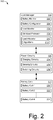
- Fig. 2 illustrates an example battery system 200 capable of implementing aspects of the techniques described herein.
- battery system 200 includes load manager 118, power circuitry 120, and battery cells 122.
- load manager 118 is implemented in software (e.g., application programming interface) or firmware of a computing device by a processor executing processor-executable instructions.
- components of load manager 118 can be implemented integral with other components of battery system 200, such as power circuitry 120 and battery cells 122 (individual or packaged).
- Load manager 118 may include any or all of the entities shown in Fig. 2 , which include battery monitor 202, battery configurator 204, load monitor 206, workload estimator 208, and load allocator 210.
- Battery monitor 202 is configured to monitor characteristics of battery cells 122, such as terminal voltage, current flow, state-of-charge (e.g., remaining capacity), temperature, age ( e.g., time or charging cycles), and the like. In some cases, battery monitor 202 may calculate or determine the internal resistance of a battery cell based on any of the other characteristics, such as age, temperature, or state-of-charge.
- Battery configurator 204 is configured to determine or access respective configuration information for battery cells 122, such as cell manufacturer, chemistry type, rated capacity, voltage and current limits (e.g., cutoffs), circuit topology, and the like. In some cases, the information of battery configurator 204 may also be useful in determining an internal resistance of a battery cell. Battery configurator 204 may store and enable other entities of load manager 118 to access this battery cell configuration information.
- Load monitor 206 monitors an amount of load power consumed by computing device 102 to operate.
- Load monitor 206 may monitor a current amount of load power (e.g., instantaneous power consumption) or load power consumed over time, such as by Coulomb counting.
- This load power is typically the amount of power provided by, or drawn from, one or more of battery cells 122 to enable operations of computing device 102.
- load monitor 206 monitors individual amounts of power drawn from each respective one of battery cells 122.
- Load monitor 206 may also monitor an amount of power applied to one or more of battery cells 122 by computing device 102 during charging.
- Workload estimator 208 estimates an amount of power that computing device 102 may consume when performing various tasks or operations. In some cases, the amount of power is estimated over duration of time, for a future duration of time, or at a future point in time. The estimation of the power may be based on tasks ( e.g., whether the screen is on (high power) or off (low power)) that computing device 102 is performing, scheduled to perform, likely to perform, and so on.
- tasks e.g., whether the screen is on (high power) or off (low power)
- workload estimator may receive information from operating system 114 that indicates a set of tasks are scheduled for execution by resources of computing device 102. Based on the set of tasks, workload estimator 208 estimates or forecasts an expected amount of current that computing device 102 will consume to perform the tasks. In some cases, workload estimator 208 provides a power consumption forecast over time based on a schedule ( e.g., waking or sleep times) or predicted order of execution for the tasks.
- a schedule e.g., waking or sleep times
- Load allocator 210 is configured to determine allocations of computing device 102's load power to be served by battery cells 122. This allocation may define respective portions of the device's load power (e.g., total required operational power) that are distributed to each of battery cells 122. The device draws its required load power according to this distribution from the different battery cells; i.e., each battery cell serves its respective portion of the device's load power. In some cases, load allocator 210 determines a load allocation scheme based on information received from other entities of load manager 118, such as current and expected workloads of computing device 102, and respective characteristics ( e.g., internal resistances) of battery cells 122. Based on this information, an allocation scheme may be configured to draw power from all or a subset of battery cells 122 to maximize an efficiency at which power is drawn from battery cells 122.
- load allocator 210 determines a load allocation scheme based on information received from other entities of load manager 118, such as current and expected workloads of computing device 102
- the efficiency at which power is drawn from battery cells 122 can be defined as a ratio of useful energy extracted from battery cells 122 to the total energy stored by battery cells 122. Ideally, all of the stored energy would be extracted from battery cells 122 as useful energy for consumption by computing device 102. At least some of the stored energy, however, is wasted or lost within battery cells 122 due to various factors, such as parasitic losses, temperature, or material breakdown. Accordingly, minimizing the wasted energy in each of battery cells 122 can be effective to maximize an overall efficiency at which power is drawn from all of battery cells 122.
- the internal resistance of the battery may also affect the amount of wasted energy under a given current level flowing through the battery. Quantitatively, simplifying the battery to an equivalent circuit of internal resistance and an ideal power source, the wasted energy can be modeled as the square of the current multiplied by the internal resistance over time. Thus, higher internal resistances cause greater amounts of wasted energy within the battery. Under fixed external circumstances, the internal resistance in turn depends on the battery's state-of-charge (SoC), the decrease of which causes an increase in the internal resistance. As such, when the battery's SoC decreases, more energy is wasted under a given load power level as the battery's internal resistance increases. Accordingly, load allocator 210 may consider a load power level or respective internal resistances of batteries when allocating workloads of computing device 102.
- SoC state-of-charge
- Load allocator 210 may also allocate the load power of computing device 102 based on load algorithms 212 (algorithms 212).
- Algorithms 212 may include general classes of allocation algorithms, such as scheduling algorithms and weighted algorithms. Scheduling algorithms include algorithms by which load power of computing device 102 is served, at any time, by one or multiple batteries. Alternately, weighted algorithms include algorithms by which load power of computing device 102 is served by all or a subset of multiple batteries. Either class of algorithm may provide a more-efficient allocation of the load power depending on a device workload or characteristics of the multiple batteries providing device power.
- scheduling algorithms include a sequential algorithm, least-internal-resistance algorithm (least-resistance algorithms), and threshold algorithm.
- the sequential algorithms allocate load power such that the load power is drawn sequentially from one battery after another. For example, one battery may be used until discharged completely, at which point power is drawn from a next battery.
- the least-resistance algorithm which also may be referred to as a 'greedy' algorithm, allocates load power based on the instantaneous power level of a load and the instantaneous respective internal resistances of the batteries. Because drawing large amounts of power from batteries having high internal resistances is highly inefficient, the least-resistance algorithm allocates high power loads to the batteries that have the least internal resistance. Additionally, the least-resistance algorithm may allocate low power loads to batteries with higher internal resistances.
- the threshold algorithm operates based on particular thresholds associated with batteries, such as thresholds for SoC or internal resistance. More specifically, the threshold algorithm may be implemented as a hybrid algorithm that implements aspects other algorithms based on thresholds. For example, a threshold algorithm may apply a sequential algorithm to multiple batteries until each battery reaches a particular threshold, such as 50% of state-of-charge. The threshold algorithm can then apply the least-resistance algorithm to allocate device load power to the partially discharged multiple batteries.
- Weighted algorithms may include a parallel algorithm and variable-weight algorithm. These algorithms allocate load power or workload of computing device 102 to multiple batteries concurrently.
- the parallel algorithm allocates the load power to all of the multiple batteries, and may be implemented by connecting the batteries together in parallel. In most cases, however, parallel connection of the batteries limits application of the parallel algorithm to similar type batteries to prevent unintended inter-battery current flow ( e.g., charging), which can damage the batteries.
- Equation 3 is the result of the connecting multiple batteries in parallel to minimize instantaneous energy loss associated with resistances R i .
- the application of the parallel algorithm may be best suited for homogenous batteries to avoid unbalanced battery circuits or unintended charging between batteries of different states.
- the variable-weight algorithm may allocate varying portions of load power to multiple batteries other than those subject to Equation 3. In some cases, the variable-weight algorithm is capable of allocating different amounts of load power to each of the multiple batteries. Because the variable-weight algorithm is capable of allocating specific load power to individual or subsets of multiple batteries, the load power can be drawn from heterogeneous batteries. Alternately or additionally, the variable-weight algorithm may allocate approximately equal portions of load power to heterogeneous batteries, such as by accounting for differences between the batteries.
- variable-weight algorithm provides an optimal efficiency over time, particularly when workloads vary between low-power and high-power. In some cases, this includes allocating low-power loads into batteries having lower SoCs (higher internal resistance) to preserve efficiencies of other batteries having higher SoCs (lower internal resistances).
- R ′ i V for any i
- y i * H ⁇ z i ⁇ j z j .
- max z ⁇ z i , s . t . ⁇ 1 ⁇ i z i C
- variable-weight algorithm may consider the derivative of a battery's internal resistance to achieve an optimal allocation of load power.
- the square-root distribution may not be achievable.
- charging between the multiple batteries may enable more-optimized workload allocations, such as when current intensities are negative.
- an optimal solution may include leveling out the internal resistances across the batteries, possibly by inter-battery recharging.
- load allocator 210 may implement any or all of the described aspects of load allocation in conjunction with any of the other algorithms described herein.
- any or all of battery monitor 202, battery configurator 204, load monitor 206, workload estimator 208, and load allocator 210 may be implemented separate from each other or combined or integrated in any suitable form.
- any of these entities, or functions thereof, may be combined generally as load manager 118, which can be implemented as a program application interface (API) or system component of operating system 114.
- API program application interface
- Battery system 200 also includes power circuitry 120, which provides an interface between load manager 118 and battery cells 122.
- power circuitry 120 may include hardware and firmware that enables computing device 102 to draw power from ( e.g., discharge), apply power to ( e.g., charge) battery cells 122, and implement various embodiments thereof.
- power circuitry 120 includes charging circuitry 214, sensing circuitry 216, and switching circuitry 218.
- Charging circuitry 214 is configured to provide current by which battery cells 122 are charged. Charging circuitry 214 may implement any suitable charging profile such as constant current, constant voltage, or custom profiles provided by load manager 118, such as intra-battery charging. In at least some embodiments, charging circuitry 214 is capable of providing different amounts of current to different respective battery cells being charged concurrently.
- Sensing circuitry 216 is configured to sense or monitor operational characteristics of battery cells 122. These operational characteristics may include a voltage level, an amount of current applied to, or an amount of current drawn from a respective one of battery cells 122. In some cases, sensing circuitry 216 may be implemented integral with charging circuitry 214, such as part of a charging controller or circuit that includes sensing elements (e.g., analog-to-digital converters (ADCs) and sense resistors).
- ADCs analog-to-digital converters
- Power circuitry 120 also includes switching circuitry 218, which enables load manager 118 to allocate and distribute load power of computing device 102 to battery cells 122. In some cases, portions of the load power are distributed to all or a subset of battery cells 122. In such cases, each portion of the distributed load power are different from each other.
- Switching circuitry 218 may be implemented using any suitable circuits, such as multiplexing circuitry that switches between battery cells 122 to facilitate connection with an appropriate set of power circuitry for battery cell sensing, power consumption, or power application ( e.g., charging).
- Battery cells 122 may include any suitable number or type of battery cells.
- battery cells 122 include battery cell-1 220, battery cell-2 222, and battery cell-N 224, where N may be any suitable integer.
- Battery cells 122 may include various homogeneous or heterogeneous combinations of cell shape, capacity, or chemistry type.
- Each of battery cells 122 may have a particular or different cell configuration, such as a chemistry type, shape, capacity, packaging, electrode size or shape, series or parallel cell arrangement, and the like. Accordingly, each of battery cells 122 may also have different parameters, such as internal resistance, capacitance, or concentration resistance.
- FIG. 300 Illustrates an example battery configuration 300 in accordance with one or more embodiments.
- Battery configuration 300 includes battery-1 302, battery-2 304, battery-3 306, and battery-4 308, each of which may be configured as any suitable type of battery. Additionally, each of batteries 302 through 308 is configured with a respective parallel bulk capacitance 310 through 316 ( e.g., super capacitor), which can be effective to mitigate a respective spike of current load on a given battery.
- a respective parallel bulk capacitance 310 through 316 e.g., super capacitor
- Each of batteries 302 through 308 provide power to or receive power from computing device 102. This power may be distributed as respective portions of current, which are shown as current I 1 318, current I 2 320, current I 3 322, and current I 4 324. These individual currents are multiplexed via battery switching circuit 326 (switching circuit 326), the summation of which is current I Device 328.
- switching circuit 326 is but one example implementation of sensing circuitry 216 as described with respect to Fig. 2 .
- battery switching circuit 326 switches rapidly between batteries 302 through 308 effective to draw current or power from each of them.
- battery switching circuit 326 may isolate one of batteries 302 through 306 and switch between a subset of the remaining batteries to continue powering computing device 102.
- battery configuration 300 may be implemented any suitable topology, such as multiple serial by multiple parallel topologies (e.g., 2S3P, 3S4P, or 2S2P).
- each serial level of battery configuration 300 may include an instance of switching circuit 326. This may enable power to be drawn from different combinations of serial batteries at a desired voltage.
- Fig. 3 also illustrates example battery model 330, which may be used to model any of the batteries or battery cells described herein.
- battery model 330 can be used by load allocator 210 to calculate or determine an efficiency at which the battery cell or battery is capable of providing power.
- parameters that affect a batteries efficiency are dynamic and may not be directly observable or measurable by traditional sensing techniques. In such cases, battery model 330 may be useful in estimating these parameters or their effects on an efficiency of the battery.
- battery model 330 includes an ideal voltage source that provides power and has an open circuit voltage 332 (Vo 332).
- Battery model 330 also includes direct current (DC) internal resistance 334 (R DCIR 334), which causes internal power loss as battery current 336 (I 336) passes through the battery.
- R DCIR 334 may be determined based on a SoC for battery model 330.
- Battery voltage 338 (V 338) represents the terminal voltage for battery model 330 and can be effected by the losses associated with the other parameters, such as when current passes through internal resistance 334 ( e.g., voltage drop associated therewith).
- the methods described herein may be used separately or in combination with each other, in whole or in part. These methods are shown as sets of operations (or acts) performed, such as through one or more entities or modules, and are not necessarily limited to the order shown for performing the operation.
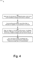
- Fig. 4 depicts method 400 for estimating an internal resistance of a battery cell, including operations performed by load manager 118 or load allocator 210.
- an amount of load power being consumed by a multi-battery device is determined.
- the multiple batteries of the device may include any suitable number or combination of batteries, such as batteries of different capacities or chemistry types.
- the amount of load power being consumed may be measured by a battery monitor. In other cases, the amount of power being consumed may be estimated.
- respective efficiencies at which multiple batteries are capable of providing power the device are determined. These efficiencies may indicate an amount of energy that will be wasted when various amounts of power are drawn from each of the batteries. In some cases, the efficiencies are determined based on a configuration or characteristic of each battery, such as chemistry type, capacity, SoC, internal resistance, age, temperature, and the like.
- battery cells 122 of smart phone 104 include a lithium polymer cell and a lithium ceramic cell.
- load allocator 210 receives information from battery monitor 202 and battery configurator 204. This information indicates that the lithium polymer cell's SoC is about 25% of a 1.9 Ahr capacity and the lithium ceramic cell's SoC is about 50% of a 210 mAhr capacity. From this information, load allocator 210 determines an internal resistance for the lithium polymer and lithium ceramic cells of 200 mOhms and 1 Ohm, respectively.
- an allocation of the load power is determined based on the respective efficiencies of the multiple batteries. This can be effective to maximize an efficiency at which the multiple batteries power the device. In some cases, the allocation is determined based on respective internal resistances of the multiple batteries and the amount of load power being consumed by the device. The determined allocation may allocate different amount of the load power to a subset or all of the multiple batteries. Alternately or additionally, some of the multiple batteries may not receive an allocation of the load power ( e.g., a portion of zero load power).
- load allocator 210 determines an allocation for smart phone 104's load power of approximately 3 W. Based on the internal resistances of the lithium polymer and lithium ceramic cells, load allocator determines that a weighted allocation of the load power will most efficiently utilize the remaining energy of the batteries. Here, assume that this allocation is approximately 500 mW of load power to the lithium ceramic cell and approximately 2500 mW of load power to the lithium polymer cell.
- a respective portion of the load power is drawn from each of the multiple batteries based on the determined allocation. This may be effective to distribute the respective portions to a subset or all of the multiple batteries. In some cases, the respective portions are distributed to each of the multiple batteries by switching circuitry. In such cases, the switching circuitry may switch between the multiple cells effective to draw the portions of load power concurrently. As noted above, the respective portions of load power may differ from each other, and some may be approximately zero ( e.g., batteries not being used).
- load allocator 210 distributes the load power of smart phone 104 to battery cells 122 via switching circuitry 218 in accordance with the determined weighted allocation. Returning to Fig. 5 , this is shown at 504, which indicates the load power drawn from the lithium polymer cell and at 506, which indicates the load power drawn from the lithium ceramic cell.
- load power 504 and 506 provide load power 502 by which smart phone 104 operates.
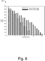
- energy profile 600 of Fig. 6 illustrates the distribution of smart phone 104's energy consumption over time.
- energy provided by the lithium polymer cell is shown as graph elements 602 and the energy provided by the lithium ceramic cell is shown as graph elements 604.
- the lithium ceramic cell provides energy until it reaches an end-of-discharge at approximate minute 14, at which point energy is provided solely by the lithium polymer cell. Because an efficiency at which energy is drawn from both batteries, the lifetime of smart phone 104 extends to 20 minutes, whereas under different battery usage patterns, the lifetime would be less.
- Fig. 7 depicts method 700 for allocating load power to multiple batteries over time, including operations performed by load manager 118 or load allocator 210.
- a current amount of load power being consumed by a multi-battery device is determined.
- the current amount of power being consumed may be classified as a high-power or low-power workload.
- the current amount of power may be calculated based on respective voltages of multiple batteries of the device and an amount of current being consumed. Alternately or additionally, indications of power consumption are received from power management circuitry of the device or the multiple batteries.
- Load monitor 206 determines that the current amount of power being consumed from battery cells 122 is approximately 5 W, which load allocator classifies as a high-power workload.
- Example classifications of workloads are illustrated by power graph 800 of Fig. 8 , in which workload are classified as high-power 802 and low-power 804. In this particular example, the current amount of power consumed by tablet computing device 106 is classified as a high-power workload 806.
- an expected amount of power that the device will consume at a future point in time is estimated.
- the expected amount of power may be estimated based on tasks or operations of the device that are scheduled for execution at the future point in time. As with the current amount of power, the expected amounts of power may also be classified as low-power or high-power workloads. In some cases, times at which the tasks or operations of the device are executed may be determined based on historical device use, daily activities of a user, or calendar information ( e.g., workday, appointment, and meeting information).
- workload estimator 208 forecasts power usage of table computing device 106 for the next several hours. To do so, workload estimator 208 queries a scheduler of operating system 114 and calendar to determine when activity levels of tablet computing device 106 are expected to change. Durations of time that correspond with these activity levels are then classified as low-power or high-power workloads, such as those shown in Fig. 8 . Note, that workloads are not necessarily scheduled for uniform durations of time, but can be estimated for activity levels or thresholds for high and low levels of power consumption. Low-power workload 808 is an example of one such workload during which device activity is low while the user sleeps.
- information concerning an efficiency at which each of the multiple batteries is capable of providing power is received.
- the information is received from an entity of the device monitoring the multiple batteries.
- a microcontroller within one of multiple batteries may transmit the information to the device.
- the information may include characteristics of a respective battery, such as the battery's SoC, internal resistance, age, temperature, remaining capacity, and the like.
- load allocator 210 receives SoC information from each of battery cells 122.
- an allocation of the load power is determined based on the current and expected amounts of power and the efficiencies of the multiple batteries. This can be effective to maximize an efficiency at which the multiple batteries power the device.
- the allocation is determined via an algorithm that analyzes the efficiency information associated with the multiple batteries. In such cases, these algorithms may include the sequential or parallel algorithms described herein, or combinations thereof.
- load allocator 210 analyzes the current workload and forecast workloads for tablet computing device 106 using the weighted algorithm. Due to the current high-power workload, load allocator 210 determines an allocation that spreads power consumption to all of battery cells 122 to minimize losses caused by their respective internal resistances.
- a portion of the current load power is drawn from each of the multiple batteries based on the determined allocation. This may be effective to distribute the portions of the current load power to a subset or all of the multiple batteries. In some cases, the respective portions are distributed to each of the multiple batteries by switching circuitry. In such cases, the switching circuitry may switch between the multiple cells effective to draw the portions of load power concurrently.
- load allocator 210 distributes the load power of laptop computing device 106 to battery cells 122 via switching circuitry 218 in accordance with the determined allocation.
- the allocation is determined using the weighted algorithm, other algorithms may also improve device runtimes of a device. For illustrative purposes, example runtimes are shown in Table 2 for a device having a lithium polymer cell and a lithium ceramic cell.
- method 700 may return to operation 702 to select another allocation using a same or different algorithm. This may occur when a workload of tablet computing device 106 transitions between high-power and low-power workloads, such as at low-power workload 808.
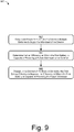
- Fig. 9 depicts method 900 for recharging across multiple batteries of a device, including operations performed by load manager 118 or load allocator 210.
- load power is drawn from a first battery of a device having multiple batteries.
- the multiple batteries of the device may include any suitable number of batteries of various configurations or states.
- the load power is drawn in accordance with an allocation determined by a scheduling algorithm.
- the scheduling algorithm may allocate the first battery's power to serve a current workload of the device.
- the current workload of the device may be a low-power workload, such as a predicted sleep or standby time for the device.
- an efficiency at which the first battery is capable of powering a future workload is not optimal.
- the determination is responsive to changes in the future workload's estimated power consumption.
- a workload estimator may forecast or re-estimate a future workload of the device as a high-power workload. For example, the workload estimator may re-estimate a series of workloads in response to unexpected user interaction.
- a scheduling algorithm may determine that, of the multiple batteries, the future high-power workload would be more-efficiently served by the first battery. Due to previous discharge, however, an efficiency at which the first battery can serve the high-power workload may not be optimal.
- the first battery is charged from a second battery of the device to increase the first battery's state-of-charge.
- the first battery is charged from all or a subset of the multiple batteries. This can be effective to improve the efficiency at which the first battery is capable of powering the future high-power workload.
- increasing the first battery's state-of-charge may decrease the first battery's internal resistance. By so doing, internal losses of the first battery are reduced while future workload is served.
- aspects of these methods may be implemented in hardware (e.g., fixed logic circuitry), firmware, a System-on-Chip (SoC), software, manual processing, or any combination thereof.
- a software implementation represents program code that performs specified tasks when executed by a computer processor, such as software, applications, routines, programs, objects, components, data structures, procedures, modules, functions, and the like.
- the program code can be stored in one or more computer-readable memory devices, both local and/or remote to a computer processor.
- the methods may also be practiced in a distributed computing environment by multiple computing devices.
- Fig. 10 illustrates various components of example device 1000 that can be implemented as any type of mobile, electronic, and/or computing device as described with reference to the previous Figs. 1-9 to implement techniques of load allocation for multi-battery devices.
- device 1000 can be implemented as one or a combination of a wired and/or wireless device, as a form of television client device (e.g., television set-top box, digital video recorder (DVR), etc.), consumer device, computer device, server device, portable computer device, user device, IoT device, communication device, video processing and/or rendering device, appliance device, gaming device, electronic device, and/or as another type of device.
- Device 1000 may also be associated with a user (e.g., a person) and/or an entity that operates the device such that a device describes logical devices that include users, software, firmware, and/or a combination of devices.
- Device 1000 includes communication modules 1002 that enable wired and/or wireless communication of device data 1004 (e.g., received data, data that is being received, data scheduled for broadcast, data packets of the data, etc.).
- Device data 1004 or other device content can include configuration settings of the device, media content stored on the device, and/or information associated with a user of the device.
- Media content stored on device 1000 can include any type of audio, video, and/or image data.
- Device 1000 includes one or more data inputs 1006 via which any type of data, media content, and/or inputs can be received, such as user-selectable inputs, messages, music, television media content, recorded video content, and any other type of audio, video, and/or image data received from any content and/or data source.
- Device 1000 also includes communication interfaces 1008, which can be implemented as any one or more of a serial and/or parallel interface, a wireless interface, any type of network interface, a modem, and as any other type of communication interface.
- Communication interfaces 1008 provide a connection and/or communication links between device 1000 and a communication network by which other electronic, computing, and communication devices communicate data with device 1000.
- Device 1000 includes one or more processors 1010 (e.g., any of microprocessors, controllers, and the like), which process various computer-executable instructions to control the operation of device 1000 and to enable techniques enabling load allocation in multi-battery devices.
- processors 1010 e.g., any of microprocessors, controllers, and the like
- device 1000 can be implemented with any one or combination of hardware, firmware, or fixed logic circuitry that is implemented in connection with processing and control circuits which are generally identified at 1012.
- device 1000 can include a system bus or data transfer system that couples the various components within the device.
- a system bus can include any one or combination of different bus structures, such as a memory bus or memory controller, a peripheral bus, a universal serial bus, and/or a processor or local bus that utilizes any of a variety of bus architectures.
- Device 1000 may be configured to operate from any suitable power source, such as battery cells 122, power circuitry 120, various external power sources (e.g., alternating-current (AC) power
- Device 1000 also includes computer-readable storage media 1014, such as one or more memory devices that enable persistent and/or non-transitory data storage (i.e., in contrast to mere signal transmission), examples of which include random access memory (RAM), non-volatile memory (e.g., any one or more of a read-only memory (ROM), flash memory, EPROM, EEPROM, etc.), and a disk storage device.
- RAM random access memory
- non-volatile memory e.g., any one or more of a read-only memory (ROM), flash memory, EPROM, EEPROM, etc.
- a disk storage device may be implemented as any type of magnetic or optical storage device, such as a hard disk drive, a recordable and/or rewriteable compact disc (CD), any type of a digital versatile disc (DVD), and the like.
- Device 1000 can also include a mass storage media device 1016.
- Computer-readable storage media 1014 provides data storage mechanisms to store device data 1004, as well as various device applications 1018 and any other types of information and/or data related to operational aspects of device 1000.
- an operating system 1020 can be maintained as a computer application with the computer-readable storage media 1014 and executed on processors 1010.
- Device applications 1018 may include a device manager, such as any form of a control application, software application, signal-processing and control module, code that is native to a particular device, a hardware abstraction layer for a particular device, and so on.
- Device applications 1018 also include any system components or modules to implement the techniques, such as load manager 118, load allocator 210, and any combination of components thereof.
Description
- This background is provided for the purpose of generally presenting a context for the instant disclosure. Unless otherwise indicated herein, material described in the background is neither expressly nor impliedly admitted to be prior art to the instant disclosure or the claims that follow.
- Batteries are often used as a power source for mobile computing and electronic devices, such as wearable devices, smart phones, tablets, and the like. Typically, a lifetime of the mobile device is determined by an amount of energy provided by the device's batteries. The amount of energy provided by the batteries, however, is often less than a total amount of energy stored by the batteries. Because of inefficiencies within the batteries and other power circuitry, at least some of the batteries' total energy is lost instead of being provided to the device. In many cases, an extent to which these inefficiencies effect the batteries' ability to provide energy depend on the batteries' condition and ways in which power is drawn from the batteries.
- For example, an internal resistance of a battery often increases as the battery's charge level declines or the battery ages. This increase of internal resistance results in additional internal energy loss as power is drawn from the battery, effectively reducing the amount of useful energy provided to the device. In some cases, such as when large amounts of power are drawn from the battery over short periods of time, these internal energy losses can substantially impact the amount of useful energy provided to the device and thus substantially deteriorate battery lifetime.
-
US 2007/103114 discloses that a portable battery-powered appliance such as a flashlight accepts at least first and second batteries. A first circuit such as a DC-to-DC converter receives power from the first battery and supplies power to the load. A second circuit such as a DC-to-DC converter receives power from the second battery and supplies electrical power to the load. - This invention provides techniques and apparatuses for load allocation in multi-battery devices, as claimed hereinafter. The load allocation may specify from which of the multiple batteries power is drawn at any given time to power the device. Further, the load allocation may also specify respective amounts of power that are drawn from a subset or all of the device's multiple batteries. By allocating the device's load power to multiple batteries of the device based on respective efficiencies at which the multiple batteries can provide power, overall energy consumption of the device can be reduced, which can prolong the device's lifetime.
- In some embodiments, a current amount of load power being consumed by a device is determined. An expected amount of load power that the device will consume at a future point in time is also estimated. Respective efficiencies at which the device's batteries are capable of providing power are determined. An allocation for the load power among the multiple batteries is then determined based on the current and expected amounts of load power and these respective efficiencies. This allocation can be effective to maximize an efficiency at which the multiple batteries power the device until the future point in time. Portions of the load power required by the device are drawn from (e.g., served by) each of the batteries in accordance with the determined allocation.
- This summary is provided to introduce simplified concepts that are further described below in the Detailed Description. This summary is not intended to identify essential features of the claimed subject matter, nor is it intended for use in determining the scope of the claimed subject matter. Techniques and/or apparatuses of load allocation for multi-battery devices are also referred to herein separately or in conjunction as the "techniques" as permitted by the context, though techniques may include or instead represent other aspects described herein.
- Embodiments enabling load allocation for multi-battery devices are described with reference to the following drawings. The same numbers are used throughout the drawings to reference like features and components:
-
Fig. 1 illustrates an example environment in which techniques of load allocation for multi-battery devices can be implemented. -
Fig. 2 illustrates an example battery system capable of implementing load allocation for multi-battery device. -
Fig. 3 illustrates an example battery configuration in accordance with one or more embodiments. -
Fig. 4 illustrates an example method for allocating load power to multiple batteries of a device. -
Fig. 5 illustrates an example allocation of load power to multiple batteries. -
Fig. 6 illustrates an example profile of useful energy provided by multiple batteries. -
Fig. 7 illustrates an example method for allocating load power to multiple batteries over time. -
Fig. 8 illustrates an example graph of a device's workload that varies over time. -
Fig 9 illustrates an example method for recharging across multiple batteries of a device. -
Fig. 10 illustrates an example device in which techniques of load allocation for multi-battery devices can be implemented. - Mobile devices often draw power from multiple batteries in order to operate. Typically, these batteries are configured in a monolithic or static topology in which power is drawn from all of the device's batteries until the batteries reach an end of their discharge. Monolithic or static battery topologies, however, often limit battery selection to batteries that have similar operating characteristics (e.g., voltage profiles and capacities), such as a set of lithium-polymer cells. This precludes the use of other or multiple types of batteries that may offer various advantages, such as different physical or electrical characteristics. Additionally, because power is drawn from all the batteries via fixed circuitry, efficiency of the mobile device's energy usage is essentially limited to the electrical characteristics of a single type of battery.
- This document describes techniques and apparatuses of load allocation for multi-battery devices. These apparatuses and techniques enable variable allocation of a device's load power to multiple batteries. The allocation of the load power is determined based on respective efficiencies at which the multiple batteries are capable of providing power. By so doing, an efficiency at which the multiple batteries power the device can be maximized. Alternately or additionally, the allocation of the load power can enable the use of heterogeneous batteries, which have different physical or electrical characteristics. This may enable device designers to select multiple types of batteries to more-efficiently serve different workload types or profiles of the mobile device.
- These are but a few examples of many ways in which the techniques enable load allocation for multi-battery devices, others of which are described below.
-
Fig. 1 illustrates anexample operating environment 100 in which techniques of load allocation for multi-battery device can be implemented.Operating environment 100 includes acomputing device 102, which is illustrated with three examples: asmart phone 104, a tablet computing device 106 (with optional keyboard), and alaptop computer 108, though other computing devices and systems, such as netbooks, health-monitoring devices, sensor nodes, smart watches, fitness accessories, Intemet-of-Things (IoT) devices, wearable computing devices, media players, and personal navigation devices may also be used. -
Computing device 102 includes computer processor(s) 110 and computer-readable storage media 112 (media 112). Media 112 includes anoperating system 114 andapplications 116, which enable various operations ofcomputing device 102.Operating system 114 manages resources ofcomputing device 102, such asprocessor 110,media 112, and the like (e.g., hardware subsystems).Applications 116 comprise tasks or threads that access the resources managed byoperating system 114 to implement various operations ofcomputing device 102.Media 112 also includes load manager 132, the implementation and use of which varies and is described in greater detail below. -
Computing device 102 alsopower circuitry 120 and battery cell(s) 122, from whichcomputing device 102 can draw power to operate. Generally,power circuitry 120 may include firmware or hardware configured to enablecomputing device 102 to draw operating power frombattery cells 122 or to apply charging power tobattery cells 122.Battery cells 122 may include any suitable number or type of rechargeable battery cells, such as lithium-ion (Lion), lithium-polymer (Li-Poly), lithium ceramic (Li-C), flexible printed circuit (FPC) Li-C, and the like. Implementations and uses ofpower circuitry 120 andbattery cells 122 vary and are described in greater detail below. -
Computing device 102 may also includedisplay 124,input mechanisms 126, and data interfaces 128. Although shown integrated with the example devices ofFig. 1 ,display 124 may be implemented separate fromcomputing device 102 via a wired or wireless display interface.Input mechanisms 126 may include gesture-sensitive sensors and devices, such as touch-based sensors and movement-tracking sensors (e.g., camera-based), buttons, touch pads, accelerometers, and microphones with accompanying voice recognition software, to name a few. In some cases,input mechanisms 126 are integrated withdisplay 124, such an in a touch-sensitive display with integrated touch-sensitive or motion-sensitive sensors. - Data interfaces 128 include any suitable wired or wireless data interfaces that enable
computing device 102 to communicate data with other devices or networks. Wired data interfaces may include serial or parallel communication interfaces, such as a universal serial bus (USB) and local-area-network (LAN). Wireless data interfaces may include transceivers or modules configured to communicate via infrastructure or peer-to-peer networks. One or more of these wireless data interfaces may be configured to communicate via near-field communication (NFC), a personal-area-network (PAN), a wireless local-area-network (WLAN), or wireless wide-area-network (WWAN). In some cases,operating system 114 or a communication manager (not shown) ofcomputing device 102 selects a data interface for communications based on characteristics of an environment in whichcomputing device 102 operates. -
Fig. 2 illustrates anexample battery system 200 capable of implementing aspects of the techniques described herein. In this particular example,battery system 200 includesload manager 118,power circuitry 120, andbattery cells 122. In some embodiments,load manager 118 is implemented in software (e.g., application programming interface) or firmware of a computing device by a processor executing processor-executable instructions. Alternately or additionally, components ofload manager 118 can be implemented integral with other components ofbattery system 200, such aspower circuitry 120 and battery cells 122 (individual or packaged). -
Load manager 118 may include any or all of the entities shown inFig. 2 , which includebattery monitor 202,battery configurator 204,load monitor 206,workload estimator 208, andload allocator 210.Battery monitor 202 is configured to monitor characteristics ofbattery cells 122, such as terminal voltage, current flow, state-of-charge (e.g., remaining capacity), temperature, age (e.g., time or charging cycles), and the like. In some cases,battery monitor 202 may calculate or determine the internal resistance of a battery cell based on any of the other characteristics, such as age, temperature, or state-of-charge. -
Battery configurator 204 is configured to determine or access respective configuration information forbattery cells 122, such as cell manufacturer, chemistry type, rated capacity, voltage and current limits (e.g., cutoffs), circuit topology, and the like. In some cases, the information ofbattery configurator 204 may also be useful in determining an internal resistance of a battery cell.Battery configurator 204 may store and enable other entities ofload manager 118 to access this battery cell configuration information. - Load monitor 206 monitors an amount of load power consumed by computing
device 102 to operate.Load monitor 206 may monitor a current amount of load power (e.g., instantaneous power consumption) or load power consumed over time, such as by Coulomb counting. This load power is typically the amount of power provided by, or drawn from, one or more ofbattery cells 122 to enable operations ofcomputing device 102. In some cases, load monitor 206 monitors individual amounts of power drawn from each respective one ofbattery cells 122.Load monitor 206 may also monitor an amount of power applied to one or more ofbattery cells 122 by computingdevice 102 during charging. -
Workload estimator 208 estimates an amount of power thatcomputing device 102 may consume when performing various tasks or operations. In some cases, the amount of power is estimated over duration of time, for a future duration of time, or at a future point in time. The estimation of the power may be based on tasks (e.g., whether the screen is on (high power) or off (low power)) thatcomputing device 102 is performing, scheduled to perform, likely to perform, and so on. - For example, workload estimator may receive information from
operating system 114 that indicates a set of tasks are scheduled for execution by resources ofcomputing device 102. Based on the set of tasks,workload estimator 208 estimates or forecasts an expected amount of current thatcomputing device 102 will consume to perform the tasks. In some cases,workload estimator 208 provides a power consumption forecast over time based on a schedule (e.g., waking or sleep times) or predicted order of execution for the tasks. -
Load allocator 210 is configured to determine allocations ofcomputing device 102's load power to be served bybattery cells 122. This allocation may define respective portions of the device's load power (e.g., total required operational power) that are distributed to each ofbattery cells 122. The device draws its required load power according to this distribution from the different battery cells; i.e., each battery cell serves its respective portion of the device's load power. In some cases,load allocator 210 determines a load allocation scheme based on information received from other entities ofload manager 118, such as current and expected workloads ofcomputing device 102, and respective characteristics (e.g., internal resistances) ofbattery cells 122. Based on this information, an allocation scheme may be configured to draw power from all or a subset ofbattery cells 122 to maximize an efficiency at which power is drawn frombattery cells 122. - Generally, the efficiency at which power is drawn from
battery cells 122 can be defined as a ratio of useful energy extracted frombattery cells 122 to the total energy stored bybattery cells 122. Ideally, all of the stored energy would be extracted frombattery cells 122 as useful energy for consumption by computingdevice 102. At least some of the stored energy, however, is wasted or lost withinbattery cells 122 due to various factors, such as parasitic losses, temperature, or material breakdown. Accordingly, minimizing the wasted energy in each ofbattery cells 122 can be effective to maximize an overall efficiency at which power is drawn from all ofbattery cells 122. - Primary factors associated with the wasted energy of a battery include power of a load drawn from the battery and the internal resistance of the battery. Intrinsic to the nature of batteries, higher amounts of load power cause more energy waste within a battery, which in turn reduces an output of useful energy. An example of load power versus energy output is shown in Table 1, where load power is denoted in capacity C such that application of the load 1C will discharge the battery in approximately 1 hour (based on rated capacity).
Table 1 Load Power Discharge Time Energy Output 6C 5.3 minutes 4.3 kilojoules 4C 14.6 minutes 8.2 kilojoules 2C 33.2 minutes 10.0 kilojoules 1C 76.3 minutes 10.7 kilojoules - As indicated by the data of Table 1, useful energy output by the battery at 6C load power is much less than that of 1C load power. This difference is due to the increased level of wasted energy that occurs when the battery is subjected to the load power of 6C.
- The internal resistance of the battery may also affect the amount of wasted energy under a given current level flowing through the battery. Quantitatively, simplifying the battery to an equivalent circuit of internal resistance and an ideal power source, the wasted energy can be modeled as the square of the current multiplied by the internal resistance over time. Thus, higher internal resistances cause greater amounts of wasted energy within the battery. Under fixed external circumstances, the internal resistance in turn depends on the battery's state-of-charge (SoC), the decrease of which causes an increase in the internal resistance. As such, when the battery's SoC decreases, more energy is wasted under a given load power level as the battery's internal resistance increases. Accordingly,
load allocator 210 may consider a load power level or respective internal resistances of batteries when allocating workloads ofcomputing device 102. -
Load allocator 210 may also allocate the load power ofcomputing device 102 based on load algorithms 212 (algorithms 212).Algorithms 212 may include general classes of allocation algorithms, such as scheduling algorithms and weighted algorithms. Scheduling algorithms include algorithms by which load power ofcomputing device 102 is served, at any time, by one or multiple batteries. Alternately, weighted algorithms include algorithms by which load power ofcomputing device 102 is served by all or a subset of multiple batteries. Either class of algorithm may provide a more-efficient allocation of the load power depending on a device workload or characteristics of the multiple batteries providing device power. - In some embodiments, scheduling algorithms include a sequential algorithm, least-internal-resistance algorithm (least-resistance algorithms), and threshold algorithm. The sequential algorithms allocate load power such that the load power is drawn sequentially from one battery after another. For example, one battery may be used until discharged completely, at which point power is drawn from a next battery. The least-resistance algorithm, which also may be referred to as a 'greedy' algorithm, allocates load power based on the instantaneous power level of a load and the instantaneous respective internal resistances of the batteries. Because drawing large amounts of power from batteries having high internal resistances is highly inefficient, the least-resistance algorithm allocates high power loads to the batteries that have the least internal resistance. Additionally, the least-resistance algorithm may allocate low power loads to batteries with higher internal resistances.
- The threshold algorithm operates based on particular thresholds associated with batteries, such as thresholds for SoC or internal resistance. More specifically, the threshold algorithm may be implemented as a hybrid algorithm that implements aspects other algorithms based on thresholds. For example, a threshold algorithm may apply a sequential algorithm to multiple batteries until each battery reaches a particular threshold, such as 50% of state-of-charge. The threshold algorithm can then apply the least-resistance algorithm to allocate device load power to the partially discharged multiple batteries.
- Weighted algorithms may include a parallel algorithm and variable-weight algorithm. These algorithms allocate load power or workload of
computing device 102 to multiple batteries concurrently. The parallel algorithm allocates the load power to all of the multiple batteries, and may be implemented by connecting the batteries together in parallel. In most cases, however, parallel connection of the batteries limits application of the parallel algorithm to similar type batteries to prevent unintended inter-battery current flow (e.g., charging), which can damage the batteries. - Typically, allocations of the parallel algorithm minimize instantaneous waste energy or maximize instantaneous energy efficiency for multiple batteries. By way of example, consider a system having n batteries that each have a resistance Ri . The system load power, or load current I, is applied to each battery as Ii . The wasted energy of the system can be minimized as shown in
Equation 1.
- Applying a standard Lagrange-multiplier approach results in an optimal solution as shown in
Equation 2.
- Further defining voltage V as -λ/2 provides
Equation 3, which is the result of the connecting multiple batteries in parallel to minimize instantaneous energy loss associated with resistances Ri.
- As noted above, however, the application of the parallel algorithm may be best suited for homogenous batteries to avoid unbalanced battery circuits or unintended charging between batteries of different states.
- The variable-weight algorithm may allocate varying portions of load power to multiple batteries other than those subject to
Equation 3. In some cases, the variable-weight algorithm is capable of allocating different amounts of load power to each of the multiple batteries. Because the variable-weight algorithm is capable of allocating specific load power to individual or subsets of multiple batteries, the load power can be drawn from heterogeneous batteries. Alternately or additionally, the variable-weight algorithm may allocate approximately equal portions of load power to heterogeneous batteries, such as by accounting for differences between the batteries. - In at least some embodiments, the variable-weight algorithm provides an optimal efficiency over time, particularly when workloads vary between low-power and high-power. In some cases, this includes allocating low-power loads into batteries having lower SoCs (higher internal resistance) to preserve efficiencies of other batteries having higher SoCs (lower internal resistances).
- By way of example, consider a system having m batteries that will power two sequential workloads for a unit length of time. The initial resistances of the m batteries are R1 through Rm , and the current of the loads are L and H. Letting x1 through xm denote current intensity of low-power load L and y1 through ym denote current intensity of high-power load H, the goal is to determine an allocation of x1...m and y1...m such that wasted energy of load H is minimized.
- Further, assume linear SoC-internal resistance relationships (e.g., curves) for batteries m, such that if current intensity x1 is drawn from battery i to power L, the resistance when powering H will be R'i = Ri + δi · xi, where δi of the internal resistance relationship is constant, but can vary between batteries. Assuming also that the internal resistances do not change when serving either load and that load allocation of xi and yi can be any real number as long as ∑xi = L and ∑yi = H, the minimization can be expressed as
Equation 4.
- To solve the minimization, zi = 1/R'i = 1/(Ri + δixi ) is defined as the conductivity of battery i powering load H. Based on the previous optimization of


Equation 5.
- From
Equation 5, optimization can be written as shown in Equation 6, where

- Solving the optimization of Equation 6 yields Equation 7, in which λ is the Lagrange-multiplier.

- From this analysis, several aspects by which the variable-weight algorithm can allocate load power can be determined. For example, optimal fractional scheduling of load L is independent of current intensity of future load H. Additionally, because zi = 1/Ri', currents x1...m should be allocated for load L such that the resistance of batteries m are proportional to the square-root of their internal resistance to SoC relationships (e.g., R'i =

- Alternately or additionally, the variable-weight algorithm may consider the derivative of a battery's internal resistance to achieve an optimal allocation of load power. In some cases, depending on the variation between internal resistances of the batteries, the square-root distribution may not be achievable. In such cases, however, charging between the multiple batteries may enable more-optimized workload allocations, such as when current intensities are negative. In yet other cases, when the batteries have similar or same internal resistance curves, an optimal solution may include leveling out the internal resistances across the batteries, possibly by inter-battery recharging.
- For implementing these concepts, the partial derivative of


- Although described in reference to the variable-weight algorithm,
load allocator 210 may implement any or all of the described aspects of load allocation in conjunction with any of the other algorithms described herein. - Although shown as disparate entities, any or all of
battery monitor 202,battery configurator 204,load monitor 206,workload estimator 208, andload allocator 210 may be implemented separate from each other or combined or integrated in any suitable form. For example, any of these entities, or functions thereof, may be combined generally asload manager 118, which can be implemented as a program application interface (API) or system component ofoperating system 114. -
Battery system 200 also includespower circuitry 120, which provides an interface betweenload manager 118 andbattery cells 122. Generally,power circuitry 120 may include hardware and firmware that enablescomputing device 102 to draw power from (e.g., discharge), apply power to (e.g., charge)battery cells 122, and implement various embodiments thereof. In this particular example,power circuitry 120 includes chargingcircuitry 214, sensingcircuitry 216, and switchingcircuitry 218. -
Charging circuitry 214 is configured to provide current by whichbattery cells 122 are charged.Charging circuitry 214 may implement any suitable charging profile such as constant current, constant voltage, or custom profiles provided byload manager 118, such as intra-battery charging. In at least some embodiments, chargingcircuitry 214 is capable of providing different amounts of current to different respective battery cells being charged concurrently. -
Sensing circuitry 216 is configured to sense or monitor operational characteristics ofbattery cells 122. These operational characteristics may include a voltage level, an amount of current applied to, or an amount of current drawn from a respective one ofbattery cells 122. In some cases, sensingcircuitry 216 may be implemented integral with chargingcircuitry 214, such as part of a charging controller or circuit that includes sensing elements (e.g., analog-to-digital converters (ADCs) and sense resistors). -
Power circuitry 120 also includes switchingcircuitry 218, which enablesload manager 118 to allocate and distribute load power ofcomputing device 102 tobattery cells 122. In some cases, portions of the load power are distributed to all or a subset ofbattery cells 122. In such cases, each portion of the distributed load power are different from each other.Switching circuitry 218 may be implemented using any suitable circuits, such as multiplexing circuitry that switches betweenbattery cells 122 to facilitate connection with an appropriate set of power circuitry for battery cell sensing, power consumption, or power application (e.g., charging). -
Battery cells 122 may include any suitable number or type of battery cells. In this particular example,battery cells 122 include battery cell-1 220, battery cell-2 222, and battery cell-N 224, where N may be any suitable integer.Battery cells 122 may include various homogeneous or heterogeneous combinations of cell shape, capacity, or chemistry type. Each ofbattery cells 122 may have a particular or different cell configuration, such as a chemistry type, shape, capacity, packaging, electrode size or shape, series or parallel cell arrangement, and the like. Accordingly, each ofbattery cells 122 may also have different parameters, such as internal resistance, capacitance, or concentration resistance. -
Fig 3 . Illustrates anexample battery configuration 300 in accordance with one or more embodiments.Battery configuration 300 includes battery-1 302, battery-2 304, battery-3 306, and battery-4 308, each of which may be configured as any suitable type of battery. Additionally, each ofbatteries 302 through 308 is configured with a respectiveparallel bulk capacitance 310 through 316 (e.g., super capacitor), which can be effective to mitigate a respective spike of current load on a given battery. - Each of
batteries 302 through 308 provide power to or receive power from computingdevice 102. This power may be distributed as respective portions of current, which are shown as current I1 318, current I2 320,current I 3 322, and current I4 324. These individual currents are multiplexed via battery switching circuit 326 (switching circuit 326), the summation of which iscurrent I Device 328. Here, note that switchingcircuit 326 is but one example implementation ofsensing circuitry 216 as described with respect toFig. 2 . In some cases, such as normal device operation,battery switching circuit 326 switches rapidly betweenbatteries 302 through 308 effective to draw current or power from each of them. In other cases,battery switching circuit 326 may isolate one ofbatteries 302 through 306 and switch between a subset of the remaining batteries to continue poweringcomputing device 102. - Although shown as a single serial by four parallel topology (1S4P),
battery configuration 300 may be implemented any suitable topology, such as multiple serial by multiple parallel topologies (e.g., 2S3P, 3S4P, or 2S2P). When implemented as a multi-serial topology, each serial level ofbattery configuration 300 may include an instance of switchingcircuit 326. This may enable power to be drawn from different combinations of serial batteries at a desired voltage. -
Fig. 3 also illustratesexample battery model 330, which may be used to model any of the batteries or battery cells described herein. Generally,battery model 330 can be used byload allocator 210 to calculate or determine an efficiency at which the battery cell or battery is capable of providing power. In some cases, parameters that affect a batteries efficiency are dynamic and may not be directly observable or measurable by traditional sensing techniques. In such cases,battery model 330 may be useful in estimating these parameters or their effects on an efficiency of the battery. - In this particular example,
battery model 330 includes an ideal voltage source that provides power and has an open circuit voltage 332 (Vo 332).Battery model 330 also includes direct current (DC) internal resistance 334 (RDCIR 334), which causes internal power loss as battery current 336 (I 336) passes through the battery. As noted above, RDCIR 334 may be determined based on a SoC forbattery model 330. Battery voltage 338 (V 338) represents the terminal voltage forbattery model 330 and can be effected by the losses associated with the other parameters, such as when current passes through internal resistance 334 (e.g., voltage drop associated therewith). - The methods described herein may be used separately or in combination with each other, in whole or in part. These methods are shown as sets of operations (or acts) performed, such as through one or more entities or modules, and are not necessarily limited to the order shown for performing the operation. In portions of the following discussion, reference may be made to the operating
environment 100 ofFig. 1 , thebattery system 200 ofFig. 2 , thebattery cell configuration 300 ofFig. 3 , and other methods and example embodiments described elsewhere herein, reference to which is made for example only. -
Fig. 4 depictsmethod 400 for estimating an internal resistance of a battery cell, including operations performed byload manager 118 orload allocator 210. - At 402, an amount of load power being consumed by a multi-battery device is determined. The multiple batteries of the device may include any suitable number or combination of batteries, such as batteries of different capacities or chemistry types. In some cases, the amount of load power being consumed may be measured by a battery monitor. In other cases, the amount of power being consumed may be estimated.
- By way of example, consider a user of
smart phone 104 making a bidirectional video call over a wireless data interface. During the video call, components ofsmart phone 104, such asprocessor 110,media 112, anddisplay 124, draw load power frombattery cells 122 to operate. Here, assume that load monitor 206 determines thatsmart phone 104 is consuming approximately 3 W of power to perform the video call. This is illustrated inpower graph 500 ofFig. 5 in whichdevice load power 502 is shown over time. - At 404, respective efficiencies at which multiple batteries are capable of providing power the device are determined. These efficiencies may indicate an amount of energy that will be wasted when various amounts of power are drawn from each of the batteries. In some cases, the efficiencies are determined based on a configuration or characteristic of each battery, such as chemistry type, capacity, SoC, internal resistance, age, temperature, and the like.
- In the context of the present example,
battery cells 122 ofsmart phone 104 include a lithium polymer cell and a lithium ceramic cell. To estimate efficiencies at which these batteries are capable of providing power,load allocator 210 receives information frombattery monitor 202 andbattery configurator 204. This information indicates that the lithium polymer cell's SoC is about 25% of a 1.9 Ahr capacity and the lithium ceramic cell's SoC is about 50% of a 210 mAhr capacity. From this information,load allocator 210 determines an internal resistance for the lithium polymer and lithium ceramic cells of 200 mOhms and 1 Ohm, respectively. - At 406, an allocation of the load power is determined based on the respective efficiencies of the multiple batteries. This can be effective to maximize an efficiency at which the multiple batteries power the device. In some cases, the allocation is determined based on respective internal resistances of the multiple batteries and the amount of load power being consumed by the device. The determined allocation may allocate different amount of the load power to a subset or all of the multiple batteries. Alternately or additionally, some of the multiple batteries may not receive an allocation of the load power (e.g., a portion of zero load power).
- Continuing the ongoing example,
load allocator 210 determines an allocation forsmart phone 104's load power of approximately 3 W. Based on the internal resistances of the lithium polymer and lithium ceramic cells, load allocator determines that a weighted allocation of the load power will most efficiently utilize the remaining energy of the batteries. Here, assume that this allocation is approximately 500 mW of load power to the lithium ceramic cell and approximately 2500 mW of load power to the lithium polymer cell. - At 408, a respective portion of the load power is drawn from each of the multiple batteries based on the determined allocation. This may be effective to distribute the respective portions to a subset or all of the multiple batteries. In some cases, the respective portions are distributed to each of the multiple batteries by switching circuitry. In such cases, the switching circuitry may switch between the multiple cells effective to draw the portions of load power concurrently. As noted above, the respective portions of load power may differ from each other, and some may be approximately zero (e.g., batteries not being used).
- Concluding the present example,
load allocator 210 distributes the load power ofsmart phone 104 tobattery cells 122 via switchingcircuitry 218 in accordance with the determined weighted allocation. Returning toFig. 5 , this is shown at 504, which indicates the load power drawn from the lithium polymer cell and at 506, which indicates the load power drawn from the lithium ceramic cell. Here, note that the combination of distributedload powers load power 502 by whichsmart phone 104 operates. - In the context of energy usage,
energy profile 600 ofFig. 6 illustrates the distribution ofsmart phone 104's energy consumption over time. Here, energy provided by the lithium polymer cell is shown asgraph elements 602 and the energy provided by the lithium ceramic cell is shown as graph elements 604. As illustrated byenergy profile 600, the lithium ceramic cell provides energy until it reaches an end-of-discharge at approximate minute 14, at which point energy is provided solely by the lithium polymer cell. Because an efficiency at which energy is drawn from both batteries, the lifetime ofsmart phone 104 extends to 20 minutes, whereas under different battery usage patterns, the lifetime would be less. -
Fig. 7 depictsmethod 700 for allocating load power to multiple batteries over time, including operations performed byload manager 118 orload allocator 210. - At 702, a current amount of load power being consumed by a multi-battery device is determined. In some cases, the current amount of power being consumed may be classified as a high-power or low-power workload. The current amount of power may be calculated based on respective voltages of multiple batteries of the device and an amount of current being consumed. Alternately or additionally, indications of power consumption are received from power management circuitry of the device or the multiple batteries.
- By way of example, consider a user conducting a meeting with
tablet computing device 106. Here, assume the user is presenting media material via a projector and hosting a video conference call.Load monitor 206 determines that the current amount of power being consumed frombattery cells 122 is approximately 5 W, which load allocator classifies as a high-power workload. Example classifications of workloads are illustrated bypower graph 800 ofFig. 8 , in which workload are classified as high-power 802 and low-power 804. In this particular example, the current amount of power consumed bytablet computing device 106 is classified as a high-power workload 806. - At 704, an expected amount of power that the device will consume at a future point in time is estimated. The expected amount of power may be estimated based on tasks or operations of the device that are scheduled for execution at the future point in time. As with the current amount of power, the expected amounts of power may also be classified as low-power or high-power workloads. In some cases, times at which the tasks or operations of the device are executed may be determined based on historical device use, daily activities of a user, or calendar information (e.g., workday, appointment, and meeting information).
- In the context of the present example,
workload estimator 208 forecasts power usage oftable computing device 106 for the next several hours. To do so,workload estimator 208 queries a scheduler ofoperating system 114 and calendar to determine when activity levels oftablet computing device 106 are expected to change. Durations of time that correspond with these activity levels are then classified as low-power or high-power workloads, such as those shown inFig. 8 . Note, that workloads are not necessarily scheduled for uniform durations of time, but can be estimated for activity levels or thresholds for high and low levels of power consumption. Low-power workload 808 is an example of one such workload during which device activity is low while the user sleeps. - At 706, information concerning an efficiency at which each of the multiple batteries is capable of providing power is received. In some cases, the information is received from an entity of the device monitoring the multiple batteries. In other cases, a microcontroller within one of multiple batteries may transmit the information to the device. The information may include characteristics of a respective battery, such as the battery's SoC, internal resistance, age, temperature, remaining capacity, and the like. Continuing the ongoing example,
load allocator 210 receives SoC information from each ofbattery cells 122. - At 708, an allocation of the load power is determined based on the current and expected amounts of power and the efficiencies of the multiple batteries. This can be effective to maximize an efficiency at which the multiple batteries power the device. In some cases, the allocation is determined via an algorithm that analyzes the efficiency information associated with the multiple batteries. In such cases, these algorithms may include the sequential or parallel algorithms described herein, or combinations thereof.
- In the context of the present example,
load allocator 210 analyzes the current workload and forecast workloads fortablet computing device 106 using the weighted algorithm. Due to the current high-power workload,load allocator 210 determines an allocation that spreads power consumption to all ofbattery cells 122 to minimize losses caused by their respective internal resistances. - At 710, a portion of the current load power is drawn from each of the multiple batteries based on the determined allocation. This may be effective to distribute the portions of the current load power to a subset or all of the multiple batteries. In some cases, the respective portions are distributed to each of the multiple batteries by switching circuitry. In such cases, the switching circuitry may switch between the multiple cells effective to draw the portions of load power concurrently.
- Concluding the present example,
load allocator 210 distributes the load power oflaptop computing device 106 tobattery cells 122 via switchingcircuitry 218 in accordance with the determined allocation. Although the allocation is determined using the weighted algorithm, other algorithms may also improve device runtimes of a device. For illustrative purposes, example runtimes are shown in Table 2 for a device having a lithium polymer cell and a lithium ceramic cell.Table 2 State-of-Charge (Lithium Polymer Cell) Algorithm 60% 10% 3% 1 % Sequential 50 29 18 5 Least- Resistance 50 50 18 5 Threshold (0.5) 50 25 18 5 Threshold (1.0) 50 25 18 5 Weighted (0.8) 50 50 48 10 Weighted (0.5) 50 50 46 7 Device Lifetime (Minutes) - Optionally,
method 700 may return tooperation 702 to select another allocation using a same or different algorithm. This may occur when a workload oftablet computing device 106 transitions between high-power and low-power workloads, such as at low-power workload 808. -
Fig. 9 depictsmethod 900 for recharging across multiple batteries of a device, including operations performed byload manager 118 orload allocator 210. - At 902, load power is drawn from a first battery of a device having multiple batteries. The multiple batteries of the device may include any suitable number of batteries of various configurations or states. In some cases, the load power is drawn in accordance with an allocation determined by a scheduling algorithm. In such cases, the scheduling algorithm may allocate the first battery's power to serve a current workload of the device. The current workload of the device may be a low-power workload, such as a predicted sleep or standby time for the device.
- At 904, it is determined that an efficiency at which the first battery is capable of powering a future workload is not optimal. In some cases, the determination is responsive to changes in the future workload's estimated power consumption. In such cases, a workload estimator may forecast or re-estimate a future workload of the device as a high-power workload. For example, the workload estimator may re-estimate a series of workloads in response to unexpected user interaction. Based on the updated workload estimate, a scheduling algorithm may determine that, of the multiple batteries, the future high-power workload would be more-efficiently served by the first battery. Due to previous discharge, however, an efficiency at which the first battery can serve the high-power workload may not be optimal.
- At 906, the first battery is charged from a second battery of the device to increase the first battery's state-of-charge. In some cases, the first battery is charged from all or a subset of the multiple batteries. This can be effective to improve the efficiency at which the first battery is capable of powering the future high-power workload. In particular, increasing the first battery's state-of-charge may decrease the first battery's internal resistance. By so doing, internal losses of the first battery are reduced while future workload is served.
- Aspects of these methods may be implemented in hardware (e.g., fixed logic circuitry), firmware, a System-on-Chip (SoC), software, manual processing, or any combination thereof. A software implementation represents program code that performs specified tasks when executed by a computer processor, such as software, applications, routines, programs, objects, components, data structures, procedures, modules, functions, and the like. The program code can be stored in one or more computer-readable memory devices, both local and/or remote to a computer processor. The methods may also be practiced in a distributed computing environment by multiple computing devices.
-
Fig. 10 illustrates various components ofexample device 1000 that can be implemented as any type of mobile, electronic, and/or computing device as described with reference to the previousFigs. 1-9 to implement techniques of load allocation for multi-battery devices. In embodiments,device 1000 can be implemented as one or a combination of a wired and/or wireless device, as a form of television client device (e.g., television set-top box, digital video recorder (DVR), etc.), consumer device, computer device, server device, portable computer device, user device, IoT device, communication device, video processing and/or rendering device, appliance device, gaming device, electronic device, and/or as another type of device.Device 1000 may also be associated with a user (e.g., a person) and/or an entity that operates the device such that a device describes logical devices that include users, software, firmware, and/or a combination of devices. -
Device 1000 includescommunication modules 1002 that enable wired and/or wireless communication of device data 1004 (e.g., received data, data that is being received, data scheduled for broadcast, data packets of the data, etc.).Device data 1004 or other device content can include configuration settings of the device, media content stored on the device, and/or information associated with a user of the device. Media content stored ondevice 1000 can include any type of audio, video, and/or image data.Device 1000 includes one ormore data inputs 1006 via which any type of data, media content, and/or inputs can be received, such as user-selectable inputs, messages, music, television media content, recorded video content, and any other type of audio, video, and/or image data received from any content and/or data source. -
Device 1000 also includescommunication interfaces 1008, which can be implemented as any one or more of a serial and/or parallel interface, a wireless interface, any type of network interface, a modem, and as any other type of communication interface.Communication interfaces 1008 provide a connection and/or communication links betweendevice 1000 and a communication network by which other electronic, computing, and communication devices communicate data withdevice 1000. -
Device 1000 includes one or more processors 1010 (e.g., any of microprocessors, controllers, and the like), which process various computer-executable instructions to control the operation ofdevice 1000 and to enable techniques enabling load allocation in multi-battery devices. Alternatively or in addition,device 1000 can be implemented with any one or combination of hardware, firmware, or fixed logic circuitry that is implemented in connection with processing and control circuits which are generally identified at 1012. Although not shown,device 1000 can include a system bus or data transfer system that couples the various components within the device. A system bus can include any one or combination of different bus structures, such as a memory bus or memory controller, a peripheral bus, a universal serial bus, and/or a processor or local bus that utilizes any of a variety of bus architectures.Device 1000 may be configured to operate from any suitable power source, such asbattery cells 122,power circuitry 120, various external power sources (e.g., alternating-current (AC) power supplies), and the like. -
Device 1000 also includes computer-readable storage media 1014, such as one or more memory devices that enable persistent and/or non-transitory data storage (i.e., in contrast to mere signal transmission), examples of which include random access memory (RAM), non-volatile memory (e.g., any one or more of a read-only memory (ROM), flash memory, EPROM, EEPROM, etc.), and a disk storage device. A disk storage device may be implemented as any type of magnetic or optical storage device, such as a hard disk drive, a recordable and/or rewriteable compact disc (CD), any type of a digital versatile disc (DVD), and the like.Device 1000 can also include a massstorage media device 1016. - Computer-
readable storage media 1014 provides data storage mechanisms to storedevice data 1004, as well asvarious device applications 1018 and any other types of information and/or data related to operational aspects ofdevice 1000. For example, anoperating system 1020 can be maintained as a computer application with the computer-readable storage media 1014 and executed onprocessors 1010.Device applications 1018 may include a device manager, such as any form of a control application, software application, signal-processing and control module, code that is native to a particular device, a hardware abstraction layer for a particular device, and so on. -
Device applications 1018 also include any system components or modules to implement the techniques, such asload manager 118,load allocator 210, and any combination of components thereof. - Although embodiments of apparatuses of load allocation for multi-battery devices have been described in language specific to features and/or methods, it is to be understood that the subject of the appended claims is not necessarily limited to the specific features or methods described. Rather, the specific features and methods are disclosed as example implementations of allocating loads in multi-battery devices.
Claims (14)
- A computer-implemented method for allocating load power among multiple batteries of a device, the method comprising:determining (402; 702), for the device having the multiple batteries (122; 220-224), an amount of the load power being consumed by the device to operate;determining (404; 706), for at least some of the multiple batteries, an efficiency at which the battery is capable of providing power;determining (406; 708), based on the respective efficiencies of at least some of the multiple batteries, an allocation of the load power to the multiple batteries effective to maximize an efficiency at which the multiple batteries power the device; anddrawing (408; 710), from each of the multiple batteries and based on the determined allocation, a respective portion of the load power to power the device.
- The computer-implemented method as described in claim 1, wherein at least two of the multiple batteries (122; 220-224) are heterogeneous batteries having different chemistry types or different capacities.
- The computer-implemented method as described in claim 1, wherein a first energy density of one of the multiple batteries (122; 220-224) is different from a second energy density of another of the multiple batteries effective to permit the battery and the other to charge at different rates.
- The computer-implemented method as described in claim 1, wherein at least two of the respective portions of the load power are different from each other.
- The computer-implemented method as described in claim 1, wherein the respective portions of the load power are consumed by the device concurrently from the multiple batteries (122; 220-224).
- The computer-implemented method as described in claim 1, wherein one of the respective portions of the load power drawn from one of the multiple batteries (122; 220-224) is approximately zero Watts of the load power.
- The computer-implemented method as described in claim 1, wherein drawing (408) the respective portions of the load power comprises causing switching circuitry (218) to switch between the multiple batteries (122; 220-224) to distribute consumption of the load power among the multiple batteries.
- The computer-implemented method as described in claim 1, wherein the efficiency at which the battery (122; 220-224) is capable of providing power is determined based on one or more of the battery's state-of-charge, internal resistance, age, cycle count, temperature, chemistry, circuit topology, or capacity.
- A system comprising:multiple batteries (122; 220-224) configured to provide power to enable operation of the system;switching circuitry (218) configured to enable the power to be drawn from each of the multiple batteries;sensing circuitry (216) configured to measure load power consumed by the system to operate; anda load manager (118) configured to perform operations comprising:determining (402; 702) an amount of the load power being consumed by the system;determining (404; 706), for each of the multiple batteries, a respective efficiency at which each of the multiple batteries is capable of providing power;determining (406; 708), based on the respective efficiencies of the multiple batteries, an allocation of the load power to the multiple batteries effective to maximize an efficiency at which the multiple batteries power the system; anddistributing (408; 710), based on the determined allocation, respective portions of the load power to each of the multiple batteries.
- The system as described in claim 9, wherein the respective efficiencies for each of the multiple batteries (122; 220-224) are determined based on the amount of load power and one or more of a respective battery's state-of-charge, internal resistance, age, cycle count, temperature, chemistry, circuit topology, or capacity.
- The system as described in claim 9, wherein at least two of the respective portions of the distributed load power are different from each other.
- The system as described in claim 9, wherein the respective portions of the distributed load power are drawn concurrently from a subset of the multiple batteries (122; 220-224).
- The system as described in claim 9, wherein the multiple batteries (122; 220-224) include at least two heterogeneous batteries having different chemistry types or different capacities.
- The system as described in claim 9, wherein the allocation is determined via an algorithm (212), the algorithm including one of a variable-weighted algorithm, sequential algorithm, least-resistance algorithm, or threshold algorithm.
Priority Applications (1)
| Application Number | Priority Date | Filing Date | Title |
|---|---|---|---|
| EP18203105.4A EP3462567A1 (en) | 2015-02-26 | 2016-02-05 | Load allocation for multi-battery devices |
Applications Claiming Priority (2)
| Application Number | Priority Date | Filing Date | Title |
|---|---|---|---|
| US14/633,009 US9748765B2 (en) | 2015-02-26 | 2015-02-26 | Load allocation for multi-battery devices |
| PCT/US2016/016671 WO2016137715A1 (en) | 2015-02-26 | 2016-02-05 | Load allocation for multi-battery devices |
Related Child Applications (2)
| Application Number | Title | Priority Date | Filing Date |
|---|---|---|---|
| EP18203105.4A Division-Into EP3462567A1 (en) | 2015-02-26 | 2016-02-05 | Load allocation for multi-battery devices |
| EP18203105.4A Division EP3462567A1 (en) | 2015-02-26 | 2016-02-05 | Load allocation for multi-battery devices |
Publications (2)
| Publication Number | Publication Date |
|---|---|
| EP3262734A1 EP3262734A1 (en) | 2018-01-03 |
| EP3262734B1 true EP3262734B1 (en) | 2018-12-05 |
Family
ID=55410257
Family Applications (2)
| Application Number | Title | Priority Date | Filing Date |
|---|---|---|---|
| EP18203105.4A Withdrawn EP3462567A1 (en) | 2015-02-26 | 2016-02-05 | Load allocation for multi-battery devices |
| EP16706100.1A Active EP3262734B1 (en) | 2015-02-26 | 2016-02-05 | Load allocation for multi-battery devices |
Family Applications Before (1)
| Application Number | Title | Priority Date | Filing Date |
|---|---|---|---|
| EP18203105.4A Withdrawn EP3462567A1 (en) | 2015-02-26 | 2016-02-05 | Load allocation for multi-battery devices |
Country Status (5)
| Country | Link |
|---|---|
| US (2) | US9748765B2 (en) |
| EP (2) | EP3462567A1 (en) |
| CN (1) | CN107408824B (en) |
| TW (1) | TW201644143A (en) |
| WO (1) | WO2016137715A1 (en) |
Cited By (1)
| Publication number | Priority date | Publication date | Assignee | Title |
|---|---|---|---|---|
| EP4060784A1 (en) | 2021-03-17 | 2022-09-21 | ETH Zurich | Power management method for multiple power source systems |
Families Citing this family (22)
| Publication number | Priority date | Publication date | Assignee | Title |
|---|---|---|---|---|
| US9696782B2 (en) | 2015-02-09 | 2017-07-04 | Microsoft Technology Licensing, Llc | Battery parameter-based power management for suppressing power spikes |
| US10158148B2 (en) | 2015-02-18 | 2018-12-18 | Microsoft Technology Licensing, Llc | Dynamically changing internal state of a battery |
| US9748765B2 (en) | 2015-02-26 | 2017-08-29 | Microsoft Technology Licensing, Llc | Load allocation for multi-battery devices |
| US9939862B2 (en) | 2015-11-13 | 2018-04-10 | Microsoft Technology Licensing, Llc | Latency-based energy storage device selection |
| US10061366B2 (en) | 2015-11-17 | 2018-08-28 | Microsoft Technology Licensing, Llc | Schedule-based energy storage device selection |
| US10224715B2 (en) * | 2015-11-24 | 2019-03-05 | The Johns Hopkins University | Intelligent power routing device |
| US9793570B2 (en) | 2015-12-04 | 2017-10-17 | Microsoft Technology Licensing, Llc | Shared electrode battery |
| DE102017201061A1 (en) * | 2017-01-24 | 2018-07-26 | Robert Bosch Gmbh | Method for operating a hybrid energy storage system |
| CN108400623B (en) * | 2017-02-08 | 2023-01-10 | 中兴通讯股份有限公司 | Terminal and method for realizing multi-path power supply management |
| US10343552B2 (en) * | 2017-02-08 | 2019-07-09 | Samsung Electronics Co., Ltd. | Heterogeneous electrical energy storage system |
| WO2018194684A1 (en) * | 2017-04-21 | 2018-10-25 | Hewlett-Packard Development Company, L.P. | Efficiency based battery configurations |
| US10739742B2 (en) * | 2017-04-27 | 2020-08-11 | Johnson Controls Technology Company | Building energy system with stochastic model predictive control |
| TWI649939B (en) | 2017-07-07 | 2019-02-01 | 財團法人工業技術研究院 | Power supply device operation method, power supply device and power supply device management system |
| US10948546B2 (en) * | 2017-10-02 | 2021-03-16 | Semiconductor Components Industries, Llc | Methods and apparatus for battery management |
| CN108539231B (en) * | 2018-03-20 | 2021-01-05 | 佛山(云浮)氢能产业与新材料发展研究院 | Coordination control method and system for multiple sets of fuel cell systems |
| US10326305B1 (en) | 2018-08-27 | 2019-06-18 | Ekergy Llc | Personal power plant system and methods of inverse energy generation |
| US10615610B1 (en) | 2019-05-28 | 2020-04-07 | Ekergy Llc | System and method for efficient charging of multiple battery cassettes |
| CN114080330A (en) * | 2019-07-04 | 2022-02-22 | 沃尔沃卡车集团 | Method for controlling electric connection of battery pack |
| US10723235B1 (en) * | 2019-08-30 | 2020-07-28 | Kitty Hawk Corporation | Flexible battery system for a vehicle |
| US20210092127A1 (en) * | 2019-09-19 | 2021-03-25 | Microsoft Technology Licensing, Llc | Writing role-backed access control to chain |
| JP2021191095A (en) * | 2020-05-29 | 2021-12-13 | 株式会社日立製作所 | Power storage system control device, power storage system, and program |
| US11089398B1 (en) | 2020-06-16 | 2021-08-10 | Apple Inc. | Battery charging control for wireless headphones |
Family Cites Families (290)
| Publication number | Priority date | Publication date | Assignee | Title |
|---|---|---|---|---|
| US4145669A (en) | 1977-02-10 | 1979-03-20 | Westinghouse Electric Corp. | Cathode electrode configuration for gas laser system |
| DE3721529A1 (en) | 1987-06-30 | 1989-01-12 | Christiansen Jens | TRIGGERING AND ISOLATION OF PSEUDO SPARK SWITCHES |
| JPH0410366A (en) | 1990-04-25 | 1992-01-14 | Otsuka Chem Co Ltd | Secondary battery having heating mechanism |
| US5523671A (en) | 1991-02-14 | 1996-06-04 | Dell Usa, L.P. | Charging system for battery powered devices |
| US5315228A (en) | 1992-01-24 | 1994-05-24 | Compaq Computer Corp. | Battery charge monitor and fuel gauge |
| US5440221A (en) | 1992-07-08 | 1995-08-08 | Benchmarg Microelectronics, Inc. | Method and apparatus for monitoring batttery capacity with charge control |
| JPH0684544A (en) | 1992-09-01 | 1994-03-25 | Nippondenso Co Ltd | Lithium secondary battery |
| FR2702885B1 (en) | 1993-03-15 | 1995-04-21 | Alcatel Converters | System for monitoring the aging of a battery and method implemented in such a system. |
| EP0752898B1 (en) | 1994-03-30 | 1998-04-29 | Alza Corporation | Reduction of skin irritation during electrotransport delivery |
| USRE38918E1 (en) | 1994-04-22 | 2005-12-13 | University Of Southern California | System and method for power-efficient charging and discharging of a capacitive load from a single source |
| US5705929A (en) | 1995-05-23 | 1998-01-06 | Fibercorp. Inc. | Battery capacity monitoring system |
| US5691742A (en) | 1995-05-24 | 1997-11-25 | Dell U.S.A., L.P. | Software battery gauge for portable computers |
| US5614332A (en) | 1995-05-26 | 1997-03-25 | Pavelle; Richard | Method and apparatus for increasing charging and discharging efficiency in batteries |
| US5684404A (en) | 1995-11-17 | 1997-11-04 | Sharp Microelectronics Technology, Inc. | System and method of measuring a battery lifetime |
| US5914585A (en) | 1996-02-20 | 1999-06-22 | Norand Corporation | Power sharing in computing systems with a plurality of electronic devices |
| JPH10136574A (en) | 1996-10-31 | 1998-05-22 | Hitachi Ltd | Battery control device |
| US5764032A (en) | 1997-03-06 | 1998-06-09 | Maxim Integrated Products, Inc. | Multiple battery switchover circuits |
| US5935724A (en) | 1997-04-04 | 1999-08-10 | Wilson Greatbatch Ltd. | Electrochemical cell having multiplate electrodes with differing discharge rate regions |
| US5818200A (en) | 1997-05-06 | 1998-10-06 | Dell U.S.A., L.P. | Dual smart battery detection system and method for portable computers |
| US6252511B1 (en) | 1997-06-20 | 2001-06-26 | Compaq Computer Corporation | Real-time battery gauge display |
| US7059769B1 (en) | 1997-06-27 | 2006-06-13 | Patrick Henry Potega | Apparatus for enabling multiple modes of operation among a plurality of devices |
| US5894212A (en) | 1997-09-19 | 1999-04-13 | Tarrytown Consulting, Inc. | Discharge monitoring and isolating system for batteries |
| SE519632C2 (en) | 1997-12-23 | 2003-03-25 | Ericsson Telefon Ab L M | Portable electronic device with thin film batteries and their use in the same |
| KR100255358B1 (en) | 1997-12-27 | 2000-05-01 | 배문한 | Bipolar battery |
| US6742003B2 (en) | 2001-04-30 | 2004-05-25 | Microsoft Corporation | Apparatus and accompanying methods for visualizing clusters of data and hierarchical cluster classifications |
| US6299998B1 (en) | 1999-03-15 | 2001-10-09 | Reveo, Inc. | Movable anode fuel cell battery |
| US6463495B1 (en) | 1999-03-29 | 2002-10-08 | Compaq Information Technologies Group, L.P. | Command and control infrastructure for a computer system using the computer's power rail |
| US6268711B1 (en) | 1999-05-05 | 2001-07-31 | Texas Instruments Incorporated | Battery manager |
| JP3323832B2 (en) | 1999-06-08 | 2002-09-09 | インターナショナル・ビジネス・マシーンズ・コーポレーション | Method of controlling charge and discharge of multiple batteries |
| US6154012A (en) | 1999-10-13 | 2000-11-28 | Xicor, Inc. | Gas gauge implementation |
| JP2001211558A (en) | 2000-01-27 | 2001-08-03 | Sanyo Electric Co Ltd | Charging method for plurality of batteries |
| JP3398703B2 (en) | 2000-02-14 | 2003-04-21 | 米沢日本電気株式会社 | Discharge circuit and duty ratio setting method |
| GB2360670B (en) | 2000-03-22 | 2004-02-04 | At & T Lab Cambridge Ltd | Power management system |
| JP3438135B2 (en) | 2000-05-19 | 2003-08-18 | 富士通株式会社 | Information device, power saving mode switching method, and recording medium storing power saving mode switching program |
| JP4759795B2 (en) | 2000-09-28 | 2011-08-31 | 株式会社Gsユアサ | Rechargeable battery remaining capacity detection method |
| US6353304B1 (en) | 2001-01-19 | 2002-03-05 | Sandia Corporation | Optimal management of batteries in electric systems |
| US6771044B1 (en) | 2001-02-08 | 2004-08-03 | Frank A. Vinciguerra | Electrical power management for recharging multiple battery-powered computers |
| US6833792B1 (en) | 2001-03-30 | 2004-12-21 | Bellsouth Intellectual Property Corporation | Battery capacity indicator in a portable computing device |
| CN1305170C (en) | 2001-04-24 | 2007-03-14 | 瑞威欧公司 | Hybrid electrochemical cell system |
| US6417646B1 (en) | 2001-05-22 | 2002-07-09 | Honeywell International Inc. | Circuit for monitoring cells of a multi-cell battery during charge |
| DE60228268D1 (en) | 2001-08-29 | 2008-09-25 | Mediatek Inc | G ONE SUPPLY VOLTAGE |
| JP2003111284A (en) | 2001-09-27 | 2003-04-11 | Nec Mobile Energy Kk | Power saving battery pack |
| JP2003194897A (en) | 2001-12-26 | 2003-07-09 | Sanyo Electric Co Ltd | Battery residual capacity operating method and pack battery |
| US6977479B2 (en) | 2002-01-08 | 2005-12-20 | Hsu Po-Jung John | Portable cell phone battery charger using solar energy as the primary source of power |
| KR100446510B1 (en) | 2002-02-04 | 2004-09-04 | 삼성전자주식회사 | Method for managing power in handheld terminal |
| US8036718B2 (en) | 2002-06-17 | 2011-10-11 | Nokia Corporation | Power management profile on a mobile device |
| US7065659B2 (en) | 2002-06-28 | 2006-06-20 | Microsoft Corporation | Power management architecture for defining component power states under a global power state and maintaining a power state floor for a specified component if a power state for the specified component under a new global power state is below the power state floor |
| US6992580B2 (en) | 2002-07-25 | 2006-01-31 | Motorola, Inc. | Portable communication device and corresponding method of operation |
| US6710578B1 (en) | 2002-08-27 | 2004-03-23 | Motorola, Inc. | Power resource management in a portable communication device |
| US6650089B1 (en) | 2002-10-16 | 2003-11-18 | Texas Instruments Incorporated | Control circuit for multiple battery systems with capacity gauge on end equipment |
| US7259538B2 (en) | 2002-11-14 | 2007-08-21 | Hewlett-Packard Development Company, L.P. | Adaptive battery conditioning employing battery chemistry determination |
| CN1754147A (en) | 2003-02-25 | 2006-03-29 | 松下电器产业株式会社 | Application program prediction method and mobile terminal |
| US7734317B2 (en) | 2003-03-18 | 2010-06-08 | Qualcomm Incorporated | Battery management |
| US7015596B2 (en) | 2003-07-03 | 2006-03-21 | Opher Pail | Electronic device display system and method |
| US6847191B1 (en) | 2003-08-13 | 2005-01-25 | Kinpo Electronics, Inc. | Power control device and the operating method thereof |
| US7020500B2 (en) | 2003-12-16 | 2006-03-28 | Michael Gabriel Saghbini | Mobile communication system powered by multiple batteries |
| JP4304600B2 (en) | 2004-01-19 | 2009-07-29 | 株式会社デンソー | Flying capacitor type battery voltage detector for vehicle |
| US7339353B1 (en) | 2004-03-10 | 2008-03-04 | Quallion Llc | Power system for managing power from multiple power sources |
| US7475267B1 (en) | 2004-03-31 | 2009-01-06 | Google, Inc. | Systems and methods for delay in startup of multiple components |
| US7339348B2 (en) | 2004-04-30 | 2008-03-04 | Dell Products L.P. | Battery pack including multiple battery cell technologies |
| JP4460946B2 (en) | 2004-05-19 | 2010-05-12 | 株式会社東海理化電機製作所 | Operation control device |
| GB2416631B (en) | 2004-07-23 | 2007-12-12 | Ford Motor Co | Energy management system and method |
| US7688033B2 (en) | 2004-09-29 | 2010-03-30 | Panasonic Ev Energy Co., Ltd. | Method for detecting state of secondary battery and device for detecting state of secondary battery |
| JP2006129588A (en) | 2004-10-28 | 2006-05-18 | Sanyo Electric Co Ltd | Power control method of secondary battery, and power unit |
| US7570018B2 (en) | 2005-02-07 | 2009-08-04 | Colgate-Palmolive Co. | Rechargeable powered device |
| US7383451B2 (en) | 2005-02-18 | 2008-06-03 | Lenovo (Singapore) Pte. Ltd. | Controlling power usage of computing device components in holistic manner |
| US7176806B2 (en) | 2005-02-23 | 2007-02-13 | Eaglepicher Energy Products Corporation | Physical key to facilitate an inactive mode for a state-of-charge indicator within a battery |
| JP2008545962A (en) | 2005-05-27 | 2008-12-18 | エルジー・ケム・リミテッド | Method and apparatus for estimating maximum output using internal resistance of battery |
| US7541693B2 (en) | 2005-06-13 | 2009-06-02 | Intel Corporation | Power distribution network for computer systems and other low-power applications |
| US7529948B2 (en) | 2005-08-25 | 2009-05-05 | Apple Inc. | Methods and apparatuses for dynamic power estimation |
| US7430679B2 (en) | 2005-08-31 | 2008-09-30 | Apple Inc. | Charging of mobile devices |
| US7531989B2 (en) | 2005-11-02 | 2009-05-12 | 02Micro International Ltd. | Battery fuel gauge circuit |
| US7688029B2 (en) * | 2005-11-08 | 2010-03-30 | Eveready Battery Company, Inc. | Portable battery powered appliance and method of operation |
| JP5089883B2 (en) | 2005-12-16 | 2012-12-05 | 日立ビークルエナジー株式会社 | Battery management device |
| US20070153371A1 (en) | 2005-12-30 | 2007-07-05 | Samsung Electronics Co., Ltd. | Display device, method of manufacturing the same, and composition for use in manufacturing the same |
| US7839121B2 (en) | 2006-03-20 | 2010-11-23 | Lg Electronics Inc. | Apparatus and method for managing power of battery packs in a portable device |
| KR101253635B1 (en) | 2006-03-22 | 2013-04-10 | 엘지전자 주식회사 | Mobile Terminal and Battery Schedualing of that |
| US7583951B2 (en) | 2006-04-14 | 2009-09-01 | Sharp Laboratories Of America, Inc. | Virtual batteries for wireless communication device |
| US7814348B2 (en) | 2006-04-26 | 2010-10-12 | Adaptive Materials, Inc. | Power management apparatus |
| US8494479B2 (en) | 2006-04-27 | 2013-07-23 | Honeywell International Inc. | System and method for optimizing power supplies in a wireless transceiver |
| US7598702B2 (en) | 2006-04-27 | 2009-10-06 | Hewlett-Packard Development Company, L.P. | Power management system and method for controlling use of power-consuming applications |
| US7948208B2 (en) | 2006-06-01 | 2011-05-24 | Mojo Mobility, Inc. | Power source, charging system, and inductive receiver for mobile devices |
| TWI426678B (en) | 2006-06-28 | 2014-02-11 | Boston Power Inc | Electronics with multiple charge rate, battery packs, methods of charging a lithium ion charge storage power supply in an electronic device and portable computers |
| US20080024007A1 (en) | 2006-07-10 | 2008-01-31 | Honeywell International Inc. | Multiple load hybrid power supply |
| US7415623B2 (en) | 2006-07-31 | 2008-08-19 | Motorola, Inc. | System for managing the power source life between multiple individually powered devices in a wired system and method of using same |
| US7716500B2 (en) | 2006-08-31 | 2010-05-11 | Ati Technologies Ulc | Power source dependent program execution |
| US7912288B2 (en) | 2006-09-21 | 2011-03-22 | Microsoft Corporation | Object detection and recognition system |
| DE102006046184B4 (en) | 2006-09-29 | 2009-01-02 | Infineon Technologies Ag | A method, apparatus and computer program product for determining an anticipated exceedance of a maximum allowable power consumption of a mobile electronic device and mobile electronic device |
| US8001407B2 (en) | 2006-10-31 | 2011-08-16 | Hewlett-Packard Development Company, L.P. | Server configured for managing power and performance |
| KR100839385B1 (en) | 2006-11-01 | 2008-06-19 | 삼성에스디아이 주식회사 | Battery management system and driving method thereof |
| US8472699B2 (en) | 2006-11-22 | 2013-06-25 | Board Of Trustees Of The Leland Stanford Junior University | Arrangement and method for three-dimensional depth image construction |
| US8890480B2 (en) | 2006-11-30 | 2014-11-18 | The Boeing Company | Health management of rechargeable batteries |
| US8001400B2 (en) | 2006-12-01 | 2011-08-16 | Apple Inc. | Power consumption management for functional preservation in a battery-powered electronic device |
| US7787405B2 (en) | 2007-01-08 | 2010-08-31 | International Business Machines Corporation | Method for utilization of active power profiles used in prediction of power reserves for remote devices |
| EP1947729B1 (en) | 2007-01-17 | 2010-09-22 | Samsung SDI Co., Ltd. | Hybrid battery |
| GB2446168A (en) | 2007-01-30 | 2008-08-06 | Third Sense Ltd | Reducing the power consumed from a battery |
| US7430675B2 (en) | 2007-02-16 | 2008-09-30 | Apple Inc. | Anticipatory power management for battery-powered electronic device |
| US20080218125A1 (en) | 2007-03-09 | 2008-09-11 | Ravi Prakash Bansal | Battery Charging System |
| JP2008232758A (en) | 2007-03-19 | 2008-10-02 | Nippon Soken Inc | Detection device for internal state of secondary cell and neural network type estimation device for quantity of state |
| KR101389448B1 (en) | 2007-03-27 | 2014-04-28 | 삼성전자주식회사 | Mobile electronic device and power management method thereof |
| US20080263375A1 (en) | 2007-04-23 | 2008-10-23 | Sundstrom Robert J | Method And System For Managing Activities In A Battery Powered Device |
| US9799098B2 (en) | 2007-04-24 | 2017-10-24 | Massachusetts Institute Of Technology | Method and apparatus for image processing |
| US8063606B2 (en) | 2007-05-11 | 2011-11-22 | Research In Motion Limited | Battery charger for a handheld computing device and an external battery |
| US8145918B2 (en) | 2007-06-28 | 2012-03-27 | International Business Machines Corporation | Monitoring system processes energy consumption |
| US20090007128A1 (en) | 2007-06-28 | 2009-01-01 | International Business Machines Corporation | method and system for orchestrating system resources with energy consumption monitoring |
| US20090016765A1 (en) | 2007-07-12 | 2009-01-15 | Kycera Mita Corporation | Image Forming Device and Image Forming Method |
| US8046180B2 (en) | 2007-07-13 | 2011-10-25 | Honeywell International Inc. | Model-based determination of power source replacement in wireless and other devices |
| EP2017938A1 (en) | 2007-07-18 | 2009-01-21 | Magna Steyr Fahrzeugtechnik AG & Co. KG | Accumulator |
| US20090085553A1 (en) | 2007-09-28 | 2009-04-02 | Pavan Kumar | Reconfigurable battery pack |
| US8097355B2 (en) | 2007-11-16 | 2012-01-17 | Microsoft Corporation | Protecting against incorrect battery polarity |
| KR20090064813A (en) | 2007-12-17 | 2009-06-22 | 삼성전자주식회사 | Method and device for dynamic changing of backlight settingtime in mobile divices |
| ITRM20080185A1 (en) | 2008-04-09 | 2009-10-10 | Michele Cunico | MOTOR VEHICLE |
| US8624560B2 (en) | 2008-04-11 | 2014-01-07 | Apple Inc. | Controlling battery charging based on current, voltage and temperature |
| JP5029488B2 (en) | 2008-05-14 | 2012-09-19 | カシオ計算機株式会社 | Electronic device, power supply control method and program |
| US8032317B2 (en) | 2008-05-15 | 2011-10-04 | The Nielsen Company (Us), Llc | System and methods for metering and analyzing energy consumption of events within a portable device |
| US8423306B2 (en) | 2008-05-22 | 2013-04-16 | Microsoft Corporation | Battery detection and user experience |
| US8242738B2 (en) | 2008-05-28 | 2012-08-14 | Texas Instruments Incorporated | Systems and methods for determining battery parameters following active operation of the battery |
| US20100121588A1 (en) | 2008-08-26 | 2010-05-13 | David Elder | Apparatus, system, and method for improving the accuracy of state of health/state of charge battery measurements using data accumulation |
| US20100070334A1 (en) | 2008-09-08 | 2010-03-18 | Dante Monteverde | Method and system for location-based mobile device predictive services |
| JP5293020B2 (en) | 2008-09-10 | 2013-09-18 | 住友化学株式会社 | Electrode mixture for non-aqueous electrolyte secondary battery, electrode and non-aqueous electrolyte secondary battery |
| AU2009295283A1 (en) | 2008-09-29 | 2011-09-15 | Wilson Lee | Multi-chemistry battery charging system and method of identifying and improved charging technique for primary and secondary dry-cell batteries |
| KR101538498B1 (en) | 2008-10-07 | 2015-07-22 | 삼성전자주식회사 | Method and appratus for battery gaging in portable terminal |
| US20100106994A1 (en) | 2008-10-27 | 2010-04-29 | David Carroll Challener | Method, apparatus, and system for adapting power consumption |
| US7944662B2 (en) | 2008-10-28 | 2011-05-17 | Steve Carkner | Multi-battery system for high voltage applications with proportional power sharing |
| US8386816B2 (en) | 2008-10-30 | 2013-02-26 | Nokia Corporation | Methods, apparatuses, and computer program products for reducing power consumption in computing devices |
| US20100123436A1 (en) | 2008-11-14 | 2010-05-20 | Symbol Technologies, Inc. | Optimized lithium-ion battery charging |
| CN201402987Y (en) | 2008-12-31 | 2010-02-10 | 广州西格美信电子科技有限公司 | Battery pack with battery management system |
| US8250384B2 (en) | 2009-01-05 | 2012-08-21 | International Business Machines Corporation | Optimizer mechanism to increase battery length for mobile devices |
| CN102308431A (en) | 2009-02-09 | 2012-01-04 | 伊克斯动力有限公司 | Discharging batteries |
| US20100213897A1 (en) | 2009-02-23 | 2010-08-26 | Lawrence Tze-Leung Tse | Battery-Cell Converter Management Systems |
| US8405332B1 (en) | 2009-02-24 | 2013-03-26 | Marvell International Ltd. | Method to eliminate current surge during spindle spin up |
| US8369904B2 (en) | 2009-02-24 | 2013-02-05 | Gary Bennis | Cell phone battery system with back-up reserve |
| US10283974B2 (en) | 2009-03-02 | 2019-05-07 | Volterra Semiconductor LLC | Systems and methods for intelligent, adaptive management of energy storage packs |
| EP2404359B1 (en) | 2009-03-02 | 2016-05-11 | Volterra Semiconductor LLC | Systems and methods for scalable configurations of intelligent energy storage packs |
| US8258748B2 (en) | 2009-03-11 | 2012-09-04 | Enfora, Inc. | Methods and apparatus for modeling, monitoring, simulating and controlling power consumption in battery-operated devices |
| US8330420B2 (en) | 2009-04-10 | 2012-12-11 | The Regents Of The University Of Michigan | Dynamically reconfigurable framework for a large-scale battery system |
| EP2417666B1 (en) | 2009-04-10 | 2019-06-12 | The Regents Of The University Of Michigan | Dynamically reconfigurable framework for a large-scale battery system |
| DE102009002468A1 (en) | 2009-04-17 | 2010-10-21 | Robert Bosch Gmbh | Determining the internal resistance of a battery cell of a traction battery when using inductive cell balancing |
| DE102009018787A1 (en) | 2009-04-24 | 2010-10-28 | Akasol Engineering Gmbh | battery module |
| US8313864B2 (en) | 2009-05-08 | 2012-11-20 | Robert Bosch Gmbh | Li-ion battery with blended electrode |
| US8190939B2 (en) | 2009-06-26 | 2012-05-29 | Microsoft Corporation | Reducing power consumption of computing devices by forecasting computing performance needs |
| US8898485B2 (en) | 2009-07-15 | 2014-11-25 | Microsoft Corporation | Power transfer between devices |
| US8754614B2 (en) | 2009-07-17 | 2014-06-17 | Tesla Motors, Inc. | Fast charging of battery using adjustable voltage control |
| GB2472051B (en) | 2009-07-22 | 2012-10-10 | Wolfson Microelectronics Plc | Power management apparatus and methods |
| US8922329B2 (en) | 2009-07-23 | 2014-12-30 | Qualcomm Incorporated | Battery charging to extend battery life and improve efficiency |
| US8508191B2 (en) * | 2009-07-29 | 2013-08-13 | The Regents Of The University Of Michigan | System for scheduling battery charge and discharge in a reconfigurable battery |
| JP2011036052A (en) | 2009-08-03 | 2011-02-17 | Sanyo Electric Co Ltd | Battery charger |
| TWI422849B (en) | 2009-08-13 | 2014-01-11 | Neotec Semiconductor Ltd | Battery capacity estimation by dcir |
| US8255716B2 (en) | 2009-08-27 | 2012-08-28 | Qualcomm Incorporated | Power optimization for data services |
| US9197081B2 (en) | 2009-08-28 | 2015-11-24 | The Charles Stark Draper Laboratory, Inc. | High-efficiency battery equalization for charging and discharging |
| US8744638B2 (en) | 2009-09-11 | 2014-06-03 | General Electric Company | Method and system for demand response in a distribution network |
| US8415926B2 (en) | 2009-10-19 | 2013-04-09 | Apple Inc. | In-situ battery health detector and end-of-life indicator |
| CN101714629A (en) | 2009-11-10 | 2010-05-26 | 苏州大学 | Tri-platform blended cathode material for lithium ion batteries and preparation method thereof |
| KR101064370B1 (en) | 2009-11-17 | 2011-09-14 | 삼성모바일디스플레이주식회사 | Organic light emitting display and driving method thereof |
| KR101613715B1 (en) | 2009-12-12 | 2016-04-20 | 삼성전자 주식회사 | Computer system and control method of the same |
| WO2011087860A2 (en) | 2009-12-22 | 2011-07-21 | G2 Llc | Battery charging and management systems and related methods |
| TW201122753A (en) | 2009-12-29 | 2011-07-01 | Ind Tech Res Inst | Voltage scaling systems |
| US8962188B2 (en) | 2010-01-07 | 2015-02-24 | Nanotek Instruments, Inc. | Anode compositions for lithium secondary batteries |
| WO2011085327A2 (en) | 2010-01-11 | 2011-07-14 | Amprius Inc. | Variable capacity cell assembly |
| US8504855B2 (en) | 2010-01-11 | 2013-08-06 | Qualcomm Incorporated | Domain specific language, compiler and JIT for dynamic power management |
| US20110187309A1 (en) | 2010-02-01 | 2011-08-04 | Acoustic Arc International Ltd. | Apparatus for automatically switching and charging multiple batteries |
| TWI404963B (en) | 2010-02-10 | 2013-08-11 | Chung Shan Inst Of Science | Method for detecting battery module status |
| WO2011114247A1 (en) | 2010-03-15 | 2011-09-22 | Brusa Elektronik Ag | Balancing the states of charge of charge accumulators |
| CN101834320B (en) | 2010-04-07 | 2012-02-15 | 清华大学 | Method and device for scheduling batteries |
| US9761920B2 (en) | 2010-04-13 | 2017-09-12 | Fluidic, Inc. | Metal-air electrochemical cell with high energy efficiency mode |
| US9912175B2 (en) | 2010-04-23 | 2018-03-06 | 9609385 Canada Inc. | Battery harvester |
| US9130376B2 (en) | 2010-04-23 | 2015-09-08 | Psion Inc. | System and method for externally controlling the charging of a battery powered device |
| US9413181B2 (en) | 2010-04-23 | 2016-08-09 | The Flewelling Ford Family Trust | Wearable power supply comprising a master cell and a slave cell |
| US8386826B2 (en) | 2010-04-23 | 2013-02-26 | Psion Inc. | System and method for managing power of a portable device |
| US8836274B2 (en) | 2010-04-26 | 2014-09-16 | Psion Inc. | System and method for displaying battery information before executing and operating system |
| US9726732B2 (en) | 2010-06-22 | 2017-08-08 | GM Global Technology Operations LLC | Adaptive battery parameter extraction and SOC estimation for lithium-ion battery |
| US8487473B2 (en) | 2010-06-24 | 2013-07-16 | Microsoft Corporation | Hierarchical power smoothing |
| US8732487B2 (en) | 2010-06-30 | 2014-05-20 | Microsoft Corporation | Predictive computing device power management |
| JP5558941B2 (en) | 2010-06-30 | 2014-07-23 | 三洋電機株式会社 | How to detect battery internal resistance |
| US8612077B2 (en) | 2010-07-07 | 2013-12-17 | Massachusetts Institute Of Technology | Hybrid electric vehicle and method of path dependent receding horizon control |
| US8423215B2 (en) | 2010-08-10 | 2013-04-16 | Tesla Motors, Inc. | Charge rate modulation of metal-air cells as a function of ambient oxygen concentration |
| US8843774B2 (en) * | 2010-08-20 | 2014-09-23 | Qualcomm Incorporated | Method and apparatus for managing battery power in response to an indication of an application being scheduled for immediate execution |
| KR20120025274A (en) | 2010-09-07 | 2012-03-15 | 삼성전자주식회사 | Method and apparatus for power controlling by cut-off voltage in a portable terminal |
| US8478567B2 (en) * | 2010-09-28 | 2013-07-02 | Qualcomm Incorporated | Systems and methods for measuring the effectiveness of a workload predictor on a mobile device |
| US20120098705A1 (en) | 2010-10-22 | 2012-04-26 | Palm, Inc. | Use of heuristic data for sending message from mobile computing device |
| US8635630B2 (en) | 2010-10-25 | 2014-01-21 | Microsoft Corporation | Application lifetime management |
| US20120102407A1 (en) | 2010-10-25 | 2012-04-26 | Microsoft Corporation | Displaying battery life resulting from setting changes |
| US20120109519A1 (en) | 2010-10-27 | 2012-05-03 | Honda Motor Co., Ltd. | System and method for routing bev to charging station |
| WO2012056417A2 (en) * | 2010-10-29 | 2012-05-03 | Sendyne Corp. | Charge redistribution method for cell arrays |
| US8569995B2 (en) | 2010-11-15 | 2013-10-29 | Volkswagen Ag | Control circuit and method for controlling a plurality of battery cells based on a determined number of coupled battery cells |
| US9182803B2 (en) | 2010-12-02 | 2015-11-10 | Advanced Micro Devices, Inc. | Load step mitigation method and apparatus |
| US20120144215A1 (en) | 2010-12-03 | 2012-06-07 | Advanced Micro Devices, Inc. | Maximum current limiting method and apparatus |
| US20120150247A1 (en) | 2010-12-08 | 2012-06-14 | Meier Giovanni C | Battery pack topology |
| EP2466718A1 (en) | 2010-12-16 | 2012-06-20 | Dialog Semiconductor GmbH | Multiple battery charger with automatic charge current adjustment |
| US8665214B2 (en) | 2010-12-29 | 2014-03-04 | Qualcomm Incorporated | Extending battery life of a portable electronic device |
| US20120210150A1 (en) | 2011-02-10 | 2012-08-16 | Alcatel-Lucent Usa Inc. | Method And Apparatus Of Smart Power Management For Mobile Communication Terminals |
| FR2972304A1 (en) | 2011-03-02 | 2012-09-07 | Commissariat Energie Atomique | BATTERY WITH INDIVIDUAL MANAGEMENT OF CELLS |
| US8949629B2 (en) | 2011-04-01 | 2015-02-03 | International Business Machines Corporation | Predicting battery power usage |
| GB201106356D0 (en) | 2011-04-14 | 2011-06-01 | Univ Strathclyde | Automated construction of usage policies |
| JP5208244B2 (en) | 2011-05-06 | 2013-06-12 | 株式会社豊田自動織機 | Negative electrode active material for lithium ion secondary battery and method for producing the same, lithium ion secondary battery and method for producing the same |
| JP5835941B2 (en) | 2011-05-17 | 2015-12-24 | 日立オートモティブシステムズ株式会社 | Nonaqueous electrolyte secondary battery |
| US8624719B2 (en) | 2011-06-03 | 2014-01-07 | Bosch Automotive Service Solutions Llc | Smart phone control and notification for an electric vehicle charging station |
| US8751845B2 (en) | 2011-06-07 | 2014-06-10 | Microsoft Corporation | Estimating and preserving battery life based on usage patterns |
| US9152202B2 (en) | 2011-06-16 | 2015-10-06 | Microsoft Technology Licensing, Llc | Mobile device operations with battery optimization |
| US9136705B2 (en) | 2011-06-17 | 2015-09-15 | GM Global Technology Operations LLC | Scalable method of proportional active state of charge balancing for managing variations in the state of health of batteries |
| CN102230953B (en) | 2011-06-20 | 2013-10-30 | 江南大学 | Method for predicting left capacity and health status of storage battery |
| US9698451B2 (en) | 2011-07-06 | 2017-07-04 | Apple Inc. | Using reference electrodes to manage batteries for portable electronic devices |
| US8958854B1 (en) | 2011-07-22 | 2015-02-17 | Cellco Partnership | Dynamic battery saver for a mobile device |
| JP5623994B2 (en) | 2011-07-29 | 2014-11-12 | 日立オートモティブシステムズ株式会社 | Power converter |
| WO2013019899A2 (en) | 2011-08-01 | 2013-02-07 | Maxim Integrated Products, Inc. | Simple and high efficiency balancing circuits and methods for hybrid batteries |
| JP5662578B2 (en) | 2011-08-05 | 2015-02-04 | パナソニックIpマネジメント株式会社 | Electronics |
| US20130043827A1 (en) | 2011-08-10 | 2013-02-21 | Nathan Daniel Weinstein | Portable power charger |
| US20130162430A1 (en) | 2011-08-18 | 2013-06-27 | Wefi, Inc. | Method and System for Charging Mobile Devices |
| US8538686B2 (en) | 2011-09-09 | 2013-09-17 | Microsoft Corporation | Transport-dependent prediction of destinations |
| US8478450B2 (en) | 2011-10-04 | 2013-07-02 | Advanergy, Inc. | Power control system and method |
| US20130088900A1 (en) * | 2011-10-10 | 2013-04-11 | Jong-Ho Park | Energy storage system and controlling method of the same |
| US8766597B2 (en) | 2011-10-21 | 2014-07-01 | Linear Technology Corporation | Optimized bi-directional balancing method and system |
| WO2013060802A1 (en) | 2011-10-25 | 2013-05-02 | St-Ericsson Sa | Battery-operated electronic device and method |
| WO2013066865A1 (en) | 2011-10-31 | 2013-05-10 | Cobasys, Llc | Intelligent charging and discharging system for parallel configuration of series cells with semiconductor switching |
| EP2590050B1 (en) | 2011-11-01 | 2017-07-26 | BlackBerry Limited | Hybrid battery system for portable electronic devices |
| US8829847B2 (en) | 2011-11-01 | 2014-09-09 | Blackberry Limited | Hybrid battery system for portable electronic devices |
| CN202424488U (en) | 2011-11-18 | 2012-09-05 | 北京汇能精电科技有限公司 | Shared-cathode-type anti-reversing-function topology circuit applied to photo-electricity storage battery |
| US8860347B2 (en) | 2011-11-29 | 2014-10-14 | Dispensing Dynamics International | Apparatus for reducing current drain and current spike impact on battery-powered electronic dispensers |
| US20130140902A1 (en) * | 2011-12-06 | 2013-06-06 | Research In Motion Limited | Fuel cell recovery time system |
| JP6224005B2 (en) | 2012-01-19 | 2017-11-01 | ナイキ イノベイト シーブイ | Power management in activity monitoring equipment |
| US9262182B2 (en) | 2012-01-25 | 2016-02-16 | Apple Inc. | Dynamic parameter profiles for electronic devices |
| US8793520B2 (en) | 2012-01-25 | 2014-07-29 | Apple Inc. | Power management of electronic devices based on charging location |
| KR101498761B1 (en) | 2012-02-02 | 2015-03-04 | 주식회사 엘지화학 | Apparatus and method of estimating state of health for battery, and battery management system using the same |
| US8594648B2 (en) | 2012-02-23 | 2013-11-26 | International Business Machines Corporation | Calendar-based power reserve |
| KR101178152B1 (en) | 2012-02-23 | 2012-08-29 | 주식회사 엘지화학 | Battery pack of novel structure |
| US9425631B2 (en) | 2012-02-27 | 2016-08-23 | Infineon Technologies Austria Ag | System and method for battery management |
| WO2013145000A1 (en) | 2012-03-28 | 2013-10-03 | 株式会社 日立製作所 | Heterogeneous battery connection device and battery system using same |
| US10690725B2 (en) | 2012-03-29 | 2020-06-23 | Atieva, Inc. | Battery state-of-charge estimation |
| KR102000295B1 (en) | 2012-04-11 | 2019-10-01 | 유니버시티 오브 써던 캘리포니아 | Runtime selection of most energy-efficient approach for services requested by mobile applications |
| WO2013165371A1 (en) | 2012-04-30 | 2013-11-07 | Hewlett-Packard Development Company, L.P. | Energy storage charging from an adjustable power source |
| EP2845252A4 (en) | 2012-05-04 | 2015-12-23 | Nano Nouvelle Pty Ltd | Battery electrode materials |
| JP6119402B2 (en) | 2012-05-29 | 2017-04-26 | 株式会社Gsユアサ | Internal resistance estimation device and internal resistance estimation method |
| DE102012209660A1 (en) | 2012-06-08 | 2013-12-12 | Robert Bosch Gmbh | Battery system and associated method for determining the internal resistance of battery cells or battery modules of the battery system |
| US9285851B2 (en) | 2012-06-22 | 2016-03-15 | Microsoft Technology Licensing, Llc | Optimizing battery use for known future load |
| EP2682840A1 (en) | 2012-07-06 | 2014-01-08 | BlackBerry Limited | Controlling current draw |
| JP5678928B2 (en) | 2012-07-31 | 2015-03-04 | トヨタ自動車株式会社 | All-solid battery and method for manufacturing the same |
| US10110130B2 (en) | 2012-08-12 | 2018-10-23 | Loai Galal Bahgat Salem | Recursive DC-DC converter |
| US9318910B2 (en) | 2012-09-06 | 2016-04-19 | Samsung Sdi Co., Ltd. | Cell balancing circuit and cell balancing method using the same |
| US20140082384A1 (en) | 2012-09-20 | 2014-03-20 | Apple Inc. | Inferring user intent from battery usage level and charging trends |
| US8768567B2 (en) | 2012-10-29 | 2014-07-01 | Broadcom Corporation | Intelligent power and control policy for automotive applications |
| US9261563B2 (en) | 2012-11-07 | 2016-02-16 | Zero Motorcycles, Inc. | System and method for improved battery charge state determination |
| US9537994B2 (en) | 2012-12-03 | 2017-01-03 | Douglas Baldasare | System and method for providing and locating public or private mobile device charging stations |
| JP6045901B2 (en) | 2012-12-18 | 2016-12-14 | オートモーティブエナジーサプライ株式会社 | Mixed electrode for non-aqueous electrolyte battery and manufacturing method thereof |
| US9189056B2 (en) | 2012-12-26 | 2015-11-17 | Intel Corporation | Mixed cell type battery module and uses thereof |
| US9012090B2 (en) | 2012-12-27 | 2015-04-21 | Palo Alto Research Center Incorporated | Advanced, high power and energy battery electrode manufactured by co-extrusion printing |
| US20140203780A1 (en) | 2013-01-24 | 2014-07-24 | Texas Instruments Incorporated | System and method for active charge and discharge current balancing in multiple parallel-connected battery packs |
| JP6157880B2 (en) * | 2013-03-04 | 2017-07-05 | 株式会社東芝 | Secondary battery system having a plurality of batteries and charge / discharge power distribution method |
| US20140266061A1 (en) | 2013-03-13 | 2014-09-18 | Manitoba Hydro International Ltd. | Heterogeneous Energy Storage System and Associated Methods |
| WO2014153034A1 (en) | 2013-03-14 | 2014-09-25 | Milwaukee Electric Tool Corporation | Power tool having multiple battery packs |
| US8972175B2 (en) | 2013-03-14 | 2015-03-03 | Qualcomm Incorporated | Navigation using crowdsourcing data |
| EP2973935B1 (en) | 2013-03-15 | 2018-10-31 | GLX Power Systems Inc. | Method and apparatus for creating a dynamically reconfigurable energy storage device |
| KR101459464B1 (en) | 2013-03-19 | 2014-11-10 | 현대자동차 주식회사 | Method and system for controlling power of fuel cell vehicle |
| CN103226184B (en) | 2013-03-20 | 2015-09-02 | 东莞宇龙通信科技有限公司 | The method of battery information and many battery terminal is obtained in many battery terminal |
| US9286568B2 (en) | 2013-05-03 | 2016-03-15 | Asurion, Llc | Battery drain analysis and prediction for wireless devices |
| US8749193B1 (en) | 2013-05-10 | 2014-06-10 | Inpower Llc | Battery protection circuit for multiple battery power supply and charging system |
| KR101595562B1 (en) | 2013-05-30 | 2016-02-18 | 주식회사 엘지화학 | Lithium secondary battery |
| US9194904B2 (en) | 2013-06-20 | 2015-11-24 | GM Global Technology Operations LLC | Systems and methods for detecting leakage paths in a battery sensing circuit |
| US9583279B2 (en) | 2013-07-01 | 2017-02-28 | Samsung Sdi Co., Ltd. | Secondary battery |
| US9671944B2 (en) | 2013-07-12 | 2017-06-06 | Microsoft Technology Licensing, Llc | Inclusion/exclusion user interface controls for range filters |
| JP6119516B2 (en) | 2013-09-02 | 2017-04-26 | ソニー株式会社 | Battery pack and electric vehicle |
| JP2015064676A (en) | 2013-09-24 | 2015-04-09 | 株式会社東芝 | Information processing device, semiconductor device, information processing method, and program |
| CN103683255A (en) | 2013-11-28 | 2014-03-26 | 成都市宏山科技有限公司 | Starting-up anti-surge circuit |
| US10128528B2 (en) | 2014-01-02 | 2018-11-13 | Johnson Controls Technology Company | Combinatorial chemistries for matching multiple batteries |
| KR20150081731A (en) | 2014-01-06 | 2015-07-15 | 삼성에스디아이 주식회사 | Battery pack, energy storage system including the battery pack, and method of operating the battery pack |
| US20150207344A1 (en) | 2014-01-17 | 2015-07-23 | General Electric Company | Configurable hybrid energy storage system and method |
| US9484587B2 (en) | 2014-02-12 | 2016-11-01 | Fluidic, Inc. | Method of operating electrochemical cells comprising electrodeposited fuel |
| US9760138B2 (en) * | 2014-04-25 | 2017-09-12 | Microsoft Technology Licensing, Llc | Load scheduling in multi-battery devices |
| US9475398B2 (en) | 2014-05-08 | 2016-10-25 | Cummins, Inc. | Optimization-based predictive method for battery charging |
| US10026998B2 (en) | 2014-05-15 | 2018-07-17 | Ford Global Technologies, Llc | Electric vehicle operation to manage battery capacity |
| US20150339415A1 (en) | 2014-05-21 | 2015-11-26 | Gary L. KLEIN | System and method for creating a simulation model via crowdsourcing |
| US9210662B1 (en) | 2014-05-29 | 2015-12-08 | Apple Inc. | Adaptive battery life extension |
| US9585100B2 (en) | 2014-09-02 | 2017-02-28 | Apple Inc. | Cold temperature power throttling at a mobile computing device |
| DE102014221547A1 (en) | 2014-10-23 | 2016-05-12 | Ford Global Technologies, Llc | Method for monitoring the state of charge of a battery |
| CN104377770B (en) * | 2014-11-19 | 2016-08-31 | 惠州市蓝微电子有限公司 | Multi-series lithium battery charging control circuit, its control method and general charger |
| US9696782B2 (en) | 2015-02-09 | 2017-07-04 | Microsoft Technology Licensing, Llc | Battery parameter-based power management for suppressing power spikes |
| US20160231387A1 (en) | 2015-02-09 | 2016-08-11 | Microsoft Microsoft Technology Licensing, LLC | Estimating Battery Cell Parameters |
| US20160241048A1 (en) | 2015-02-18 | 2016-08-18 | Microsoft Technology Licensing, Llc | Battery Assembly Combining Multiple Different Batteries |
| US10158148B2 (en) | 2015-02-18 | 2018-12-18 | Microsoft Technology Licensing, Llc | Dynamically changing internal state of a battery |
| US20160248266A1 (en) | 2015-02-19 | 2016-08-25 | Microsoft Technology Licensing, Llc | Heterogeneous Battery Cell Charging |
| US20160248125A1 (en) | 2015-02-19 | 2016-08-25 | Microsoft Technology Licensing, Llc | Heterogeneous Battery Cell Switching |
| US9748765B2 (en) | 2015-02-26 | 2017-08-29 | Microsoft Technology Licensing, Llc | Load allocation for multi-battery devices |
| US20160275400A1 (en) | 2015-03-19 | 2016-09-22 | Microsoft Technology Licensing, Llc | Device Charging Discovery Service |
| JP2018508965A (en) | 2015-03-19 | 2018-03-29 | フルイディック, インク.Fluidic, Inc. | Electrochemical cell with electrodeposited fuel |
| GB2537406B (en) | 2015-04-16 | 2017-10-18 | Oxis Energy Ltd | Method and apparatus for determining the state of health and state of charge of lithium sulfur batteries |
| AU2016270566A1 (en) | 2015-06-04 | 2018-01-25 | Nantenergy, Inc. | Hybrid electrochemical cell systems and methods of operation |
| US20170108906A1 (en) | 2015-10-16 | 2017-04-20 | Microsoft Technology Licensing, Llc | Single Fuel Gauge for Multiple Energy Storage Devices |
| US9939862B2 (en) | 2015-11-13 | 2018-04-10 | Microsoft Technology Licensing, Llc | Latency-based energy storage device selection |
| US10061366B2 (en) | 2015-11-17 | 2018-08-28 | Microsoft Technology Licensing, Llc | Schedule-based energy storage device selection |
| US9793570B2 (en) | 2015-12-04 | 2017-10-17 | Microsoft Technology Licensing, Llc | Shared electrode battery |
| JP2017204407A (en) * | 2016-05-12 | 2017-11-16 | トヨタ自動車株式会社 | Fuel cell system and control method thereof |
-
2015
- 2015-02-26 US US14/633,009 patent/US9748765B2/en active Active
-
2016
- 2016-02-05 CN CN201680012445.9A patent/CN107408824B/en active Active
- 2016-02-05 EP EP18203105.4A patent/EP3462567A1/en not_active Withdrawn
- 2016-02-05 EP EP16706100.1A patent/EP3262734B1/en active Active
- 2016-02-05 WO PCT/US2016/016671 patent/WO2016137715A1/en active Application Filing
- 2016-02-26 TW TW105105848A patent/TW201644143A/en unknown
-
2017
- 2017-07-14 US US15/650,666 patent/US10263421B2/en active Active
Non-Patent Citations (1)
| Title |
|---|
| None * |
Cited By (2)
| Publication number | Priority date | Publication date | Assignee | Title |
|---|---|---|---|---|
| EP4060784A1 (en) | 2021-03-17 | 2022-09-21 | ETH Zurich | Power management method for multiple power source systems |
| WO2022194563A1 (en) | 2021-03-17 | 2022-09-22 | Eth Zurich | Power management method for multiple power source systems |
Also Published As
| Publication number | Publication date |
|---|---|
| US9748765B2 (en) | 2017-08-29 |
| TW201644143A (en) | 2016-12-16 |
| CN107408824A (en) | 2017-11-28 |
| WO2016137715A1 (en) | 2016-09-01 |
| US20170317493A1 (en) | 2017-11-02 |
| CN107408824B (en) | 2020-04-14 |
| US20160254664A1 (en) | 2016-09-01 |
| US10263421B2 (en) | 2019-04-16 |
| EP3262734A1 (en) | 2018-01-03 |
| EP3462567A1 (en) | 2019-04-03 |
Similar Documents
| Publication | Publication Date | Title |
|---|---|---|
| EP3262734B1 (en) | Load allocation for multi-battery devices | |
| EP3256927B1 (en) | Suppressing power spikes | |
| US20160231387A1 (en) | Estimating Battery Cell Parameters | |
| JP6667502B2 (en) | Load scheduling in multiple battery devices | |
| Xie et al. | State of health aware charge management in hybrid electrical energy storage systems | |
| US20210135478A1 (en) | Workload dependent load-sharing mechanism in multi-battery system, and adaptive charging and discharging for a hybrid battery | |
| Yue et al. | Reinforcement learning based dynamic power management with a hybrid power supply | |
| US20220407337A1 (en) | Predictable battery power management apparatus and method | |
| US20220224135A1 (en) | Context-based battery charging apparatus and method | |
| Chen et al. | Battery-aware design exploration of scheduling policies for multi-sensor devices | |
| TWI646750B (en) | Energy storage system and charging and discharging method | |
| US11073885B2 (en) | Battery architecture for variable loads and output topologies in an information handling system | |
| CN106100037B (en) | A kind of charging method and charging unit | |
| WO2022001304A1 (en) | Device power supply method, system, and related device | |
| Elmalaki et al. | A Case for Battery {Charging-Aware} Power Management and Deferrable Task Scheduling in Smartphones | |
| Hasanloo et al. | Harvesting-aware charge management in embedded systems equipped with a hybrid electrical energy storage | |
| EP4109707A1 (en) | Adaptive burst power and fast battery charging apparatus and method | |
| CN111064263B (en) | Voltage control method, photovoltaic power supply device and system | |
| CN110707679B (en) | Voltage control method and photovoltaic power supply device and system | |
| Yan et al. | Toward Customized Hybrid Fuel-Cell and Battery-powered Mobile Device for Individual Users |
Legal Events
| Date | Code | Title | Description |
|---|---|---|---|
| STAA | Information on the status of an ep patent application or granted ep patent |
Free format text: STATUS: THE INTERNATIONAL PUBLICATION HAS BEEN MADE |
|
| PUAI | Public reference made under article 153(3) epc to a published international application that has entered the european phase |
Free format text: ORIGINAL CODE: 0009012 |
|
| STAA | Information on the status of an ep patent application or granted ep patent |
Free format text: STATUS: REQUEST FOR EXAMINATION WAS MADE |
|
| 17P | Request for examination filed |
Effective date: 20170810 |
|
| AK | Designated contracting states |
Kind code of ref document: A1 Designated state(s): AL AT BE BG CH CY CZ DE DK EE ES FI FR GB GR HR HU IE IS IT LI LT LU LV MC MK MT NL NO PL PT RO RS SE SI SK SM TR |
|
| AX | Request for extension of the european patent |
Extension state: BA ME |
|
| DAV | Request for validation of the european patent (deleted) | ||
| DAX | Request for extension of the european patent (deleted) | ||
| REG | Reference to a national code |
Ref country code: DE Ref legal event code: R079 Ref document number: 602016007855 Country of ref document: DE Free format text: PREVIOUS MAIN CLASS: H02J0007000000 Ipc: H02J0001000000 |
|
| GRAP | Despatch of communication of intention to grant a patent |
Free format text: ORIGINAL CODE: EPIDOSNIGR1 |
|
| STAA | Information on the status of an ep patent application or granted ep patent |
Free format text: STATUS: GRANT OF PATENT IS INTENDED |
|
| RIC1 | Information provided on ipc code assigned before grant |
Ipc: H02J 7/00 20060101ALI20180607BHEP Ipc: H02J 1/00 20060101AFI20180607BHEP |
|
| INTG | Intention to grant announced |
Effective date: 20180625 |
|
| GRAS | Grant fee paid |
Free format text: ORIGINAL CODE: EPIDOSNIGR3 |
|
| GRAA | (expected) grant |
Free format text: ORIGINAL CODE: 0009210 |
|
| STAA | Information on the status of an ep patent application or granted ep patent |
Free format text: STATUS: THE PATENT HAS BEEN GRANTED |
|
| AK | Designated contracting states |
Kind code of ref document: B1 Designated state(s): AL AT BE BG CH CY CZ DE DK EE ES FI FR GB GR HR HU IE IS IT LI LT LU LV MC MK MT NL NO PL PT RO RS SE SI SK SM TR |
|
| REG | Reference to a national code |
Ref country code: GB Ref legal event code: FG4D |
|
| REG | Reference to a national code |
Ref country code: CH Ref legal event code: EP |
|
| REG | Reference to a national code |
Ref country code: AT Ref legal event code: REF Ref document number: 1074253 Country of ref document: AT Kind code of ref document: T Effective date: 20181215 |
|
| REG | Reference to a national code |
Ref country code: IE Ref legal event code: FG4D |
|
| REG | Reference to a national code |
Ref country code: DE Ref legal event code: R096 Ref document number: 602016007855 Country of ref document: DE |
|
| REG | Reference to a national code |
Ref country code: NL Ref legal event code: FP |
|
| REG | Reference to a national code |
Ref country code: AT Ref legal event code: MK05 Ref document number: 1074253 Country of ref document: AT Kind code of ref document: T Effective date: 20181205 |
|
| REG | Reference to a national code |
Ref country code: LT Ref legal event code: MG4D |
|
| PG25 | Lapsed in a contracting state [announced via postgrant information from national office to epo] |
Ref country code: ES Free format text: LAPSE BECAUSE OF FAILURE TO SUBMIT A TRANSLATION OF THE DESCRIPTION OR TO PAY THE FEE WITHIN THE PRESCRIBED TIME-LIMIT Effective date: 20181205 Ref country code: BG Free format text: LAPSE BECAUSE OF FAILURE TO SUBMIT A TRANSLATION OF THE DESCRIPTION OR TO PAY THE FEE WITHIN THE PRESCRIBED TIME-LIMIT Effective date: 20190305 Ref country code: NO Free format text: LAPSE BECAUSE OF FAILURE TO SUBMIT A TRANSLATION OF THE DESCRIPTION OR TO PAY THE FEE WITHIN THE PRESCRIBED TIME-LIMIT Effective date: 20190305 Ref country code: HR Free format text: LAPSE BECAUSE OF FAILURE TO SUBMIT A TRANSLATION OF THE DESCRIPTION OR TO PAY THE FEE WITHIN THE PRESCRIBED TIME-LIMIT Effective date: 20181205 Ref country code: LT Free format text: LAPSE BECAUSE OF FAILURE TO SUBMIT A TRANSLATION OF THE DESCRIPTION OR TO PAY THE FEE WITHIN THE PRESCRIBED TIME-LIMIT Effective date: 20181205 Ref country code: LV Free format text: LAPSE BECAUSE OF FAILURE TO SUBMIT A TRANSLATION OF THE DESCRIPTION OR TO PAY THE FEE WITHIN THE PRESCRIBED TIME-LIMIT Effective date: 20181205 Ref country code: FI Free format text: LAPSE BECAUSE OF FAILURE TO SUBMIT A TRANSLATION OF THE DESCRIPTION OR TO PAY THE FEE WITHIN THE PRESCRIBED TIME-LIMIT Effective date: 20181205 Ref country code: AT Free format text: LAPSE BECAUSE OF FAILURE TO SUBMIT A TRANSLATION OF THE DESCRIPTION OR TO PAY THE FEE WITHIN THE PRESCRIBED TIME-LIMIT Effective date: 20181205 |
|
| PG25 | Lapsed in a contracting state [announced via postgrant information from national office to epo] |
Ref country code: AL Free format text: LAPSE BECAUSE OF FAILURE TO SUBMIT A TRANSLATION OF THE DESCRIPTION OR TO PAY THE FEE WITHIN THE PRESCRIBED TIME-LIMIT Effective date: 20181205 Ref country code: SE Free format text: LAPSE BECAUSE OF FAILURE TO SUBMIT A TRANSLATION OF THE DESCRIPTION OR TO PAY THE FEE WITHIN THE PRESCRIBED TIME-LIMIT Effective date: 20181205 Ref country code: GR Free format text: LAPSE BECAUSE OF FAILURE TO SUBMIT A TRANSLATION OF THE DESCRIPTION OR TO PAY THE FEE WITHIN THE PRESCRIBED TIME-LIMIT Effective date: 20190306 Ref country code: RS Free format text: LAPSE BECAUSE OF FAILURE TO SUBMIT A TRANSLATION OF THE DESCRIPTION OR TO PAY THE FEE WITHIN THE PRESCRIBED TIME-LIMIT Effective date: 20181205 |
|
| PG25 | Lapsed in a contracting state [announced via postgrant information from national office to epo] |
Ref country code: CZ Free format text: LAPSE BECAUSE OF FAILURE TO SUBMIT A TRANSLATION OF THE DESCRIPTION OR TO PAY THE FEE WITHIN THE PRESCRIBED TIME-LIMIT Effective date: 20181205 Ref country code: PT Free format text: LAPSE BECAUSE OF FAILURE TO SUBMIT A TRANSLATION OF THE DESCRIPTION OR TO PAY THE FEE WITHIN THE PRESCRIBED TIME-LIMIT Effective date: 20190405 Ref country code: IT Free format text: LAPSE BECAUSE OF FAILURE TO SUBMIT A TRANSLATION OF THE DESCRIPTION OR TO PAY THE FEE WITHIN THE PRESCRIBED TIME-LIMIT Effective date: 20181205 Ref country code: PL Free format text: LAPSE BECAUSE OF FAILURE TO SUBMIT A TRANSLATION OF THE DESCRIPTION OR TO PAY THE FEE WITHIN THE PRESCRIBED TIME-LIMIT Effective date: 20181205 |
|
| PG25 | Lapsed in a contracting state [announced via postgrant information from national office to epo] |
Ref country code: SK Free format text: LAPSE BECAUSE OF FAILURE TO SUBMIT A TRANSLATION OF THE DESCRIPTION OR TO PAY THE FEE WITHIN THE PRESCRIBED TIME-LIMIT Effective date: 20181205 Ref country code: RO Free format text: LAPSE BECAUSE OF FAILURE TO SUBMIT A TRANSLATION OF THE DESCRIPTION OR TO PAY THE FEE WITHIN THE PRESCRIBED TIME-LIMIT Effective date: 20181205 Ref country code: IS Free format text: LAPSE BECAUSE OF FAILURE TO SUBMIT A TRANSLATION OF THE DESCRIPTION OR TO PAY THE FEE WITHIN THE PRESCRIBED TIME-LIMIT Effective date: 20190405 Ref country code: EE Free format text: LAPSE BECAUSE OF FAILURE TO SUBMIT A TRANSLATION OF THE DESCRIPTION OR TO PAY THE FEE WITHIN THE PRESCRIBED TIME-LIMIT Effective date: 20181205 Ref country code: SM Free format text: LAPSE BECAUSE OF FAILURE TO SUBMIT A TRANSLATION OF THE DESCRIPTION OR TO PAY THE FEE WITHIN THE PRESCRIBED TIME-LIMIT Effective date: 20181205 |
|
| REG | Reference to a national code |
Ref country code: DE Ref legal event code: R097 Ref document number: 602016007855 Country of ref document: DE |
|
| REG | Reference to a national code |
Ref country code: CH Ref legal event code: PL |
|
| PLBE | No opposition filed within time limit |
Free format text: ORIGINAL CODE: 0009261 |
|
| STAA | Information on the status of an ep patent application or granted ep patent |
Free format text: STATUS: NO OPPOSITION FILED WITHIN TIME LIMIT |
|
| PG25 | Lapsed in a contracting state [announced via postgrant information from national office to epo] |
Ref country code: LU Free format text: LAPSE BECAUSE OF NON-PAYMENT OF DUE FEES Effective date: 20190205 Ref country code: MC Free format text: LAPSE BECAUSE OF FAILURE TO SUBMIT A TRANSLATION OF THE DESCRIPTION OR TO PAY THE FEE WITHIN THE PRESCRIBED TIME-LIMIT Effective date: 20181205 Ref country code: DK Free format text: LAPSE BECAUSE OF FAILURE TO SUBMIT A TRANSLATION OF THE DESCRIPTION OR TO PAY THE FEE WITHIN THE PRESCRIBED TIME-LIMIT Effective date: 20181205 |
|
| 26N | No opposition filed |
Effective date: 20190906 |
|
| REG | Reference to a national code |
Ref country code: BE Ref legal event code: MM Effective date: 20190228 |
|
| REG | Reference to a national code |
Ref country code: IE Ref legal event code: MM4A |
|
| REG | Reference to a national code |
Ref country code: DE Ref legal event code: R082 Ref document number: 602016007855 Country of ref document: DE |
|
| PG25 | Lapsed in a contracting state [announced via postgrant information from national office to epo] |
Ref country code: CH Free format text: LAPSE BECAUSE OF NON-PAYMENT OF DUE FEES Effective date: 20190228 Ref country code: LI Free format text: LAPSE BECAUSE OF NON-PAYMENT OF DUE FEES Effective date: 20190228 |
|
| PG25 | Lapsed in a contracting state [announced via postgrant information from national office to epo] |
Ref country code: IE Free format text: LAPSE BECAUSE OF NON-PAYMENT OF DUE FEES Effective date: 20190205 |
|
| PG25 | Lapsed in a contracting state [announced via postgrant information from national office to epo] |
Ref country code: BE Free format text: LAPSE BECAUSE OF NON-PAYMENT OF DUE FEES Effective date: 20190228 |
|
| PG25 | Lapsed in a contracting state [announced via postgrant information from national office to epo] |
Ref country code: TR Free format text: LAPSE BECAUSE OF FAILURE TO SUBMIT A TRANSLATION OF THE DESCRIPTION OR TO PAY THE FEE WITHIN THE PRESCRIBED TIME-LIMIT Effective date: 20181205 |
|
| PG25 | Lapsed in a contracting state [announced via postgrant information from national office to epo] |
Ref country code: MT Free format text: LAPSE BECAUSE OF NON-PAYMENT OF DUE FEES Effective date: 20190205 |
|
| PG25 | Lapsed in a contracting state [announced via postgrant information from national office to epo] |
Ref country code: CY Free format text: LAPSE BECAUSE OF FAILURE TO SUBMIT A TRANSLATION OF THE DESCRIPTION OR TO PAY THE FEE WITHIN THE PRESCRIBED TIME-LIMIT Effective date: 20181205 |
|
| PG25 | Lapsed in a contracting state [announced via postgrant information from national office to epo] |
Ref country code: HU Free format text: LAPSE BECAUSE OF FAILURE TO SUBMIT A TRANSLATION OF THE DESCRIPTION OR TO PAY THE FEE WITHIN THE PRESCRIBED TIME-LIMIT; INVALID AB INITIO Effective date: 20160205 |
|
| PG25 | Lapsed in a contracting state [announced via postgrant information from national office to epo] |
Ref country code: SI Free format text: LAPSE BECAUSE OF FAILURE TO SUBMIT A TRANSLATION OF THE DESCRIPTION OR TO PAY THE FEE WITHIN THE PRESCRIBED TIME-LIMIT Effective date: 20181205 |
|
| PG25 | Lapsed in a contracting state [announced via postgrant information from national office to epo] |
Ref country code: MK Free format text: LAPSE BECAUSE OF FAILURE TO SUBMIT A TRANSLATION OF THE DESCRIPTION OR TO PAY THE FEE WITHIN THE PRESCRIBED TIME-LIMIT Effective date: 20181205 |
|
| PGFP | Annual fee paid to national office [announced via postgrant information from national office to epo] |
Ref country code: GB Payment date: 20221230 Year of fee payment: 8 |
|
| PGFP | Annual fee paid to national office [announced via postgrant information from national office to epo] |
Ref country code: FR Payment date: 20230110 Year of fee payment: 8 |
|
| PGFP | Annual fee paid to national office [announced via postgrant information from national office to epo] |
Ref country code: DE Payment date: 20221230 Year of fee payment: 8 |
|
| P01 | Opt-out of the competence of the unified patent court (upc) registered |
Effective date: 20230429 |
|
| PGFP | Annual fee paid to national office [announced via postgrant information from national office to epo] |
Ref country code: NL Payment date: 20230113 Year of fee payment: 8 |
|
| PGFP | Annual fee paid to national office [announced via postgrant information from national office to epo] |
Ref country code: NL Payment date: 20240123 Year of fee payment: 9 |