US9939862B2 - Latency-based energy storage device selection - Google Patents
Latency-based energy storage device selection Download PDFInfo
- Publication number
- US9939862B2 US9939862B2 US14/941,416 US201514941416A US9939862B2 US 9939862 B2 US9939862 B2 US 9939862B2 US 201514941416 A US201514941416 A US 201514941416A US 9939862 B2 US9939862 B2 US 9939862B2
- Authority
- US
- United States
- Prior art keywords
- energy storage
- latency
- power
- storage devices
- computing device
- Prior art date
- Legal status (The legal status is an assumption and is not a legal conclusion. Google has not performed a legal analysis and makes no representation as to the accuracy of the status listed.)
- Active, expires
Links
Images


Classifications
-
- G—PHYSICS
- G06—COMPUTING; CALCULATING OR COUNTING
- G06F—ELECTRIC DIGITAL DATA PROCESSING
- G06F1/00—Details not covered by groups G06F3/00 - G06F13/00 and G06F21/00
- G06F1/26—Power supply means, e.g. regulation thereof
- G06F1/263—Arrangements for using multiple switchable power supplies, e.g. battery and AC
-
- G—PHYSICS
- G06—COMPUTING; CALCULATING OR COUNTING
- G06F—ELECTRIC DIGITAL DATA PROCESSING
- G06F1/00—Details not covered by groups G06F3/00 - G06F13/00 and G06F21/00
- G06F1/26—Power supply means, e.g. regulation thereof
-
- G—PHYSICS
- G06—COMPUTING; CALCULATING OR COUNTING
- G06F—ELECTRIC DIGITAL DATA PROCESSING
- G06F1/00—Details not covered by groups G06F3/00 - G06F13/00 and G06F21/00
- G06F1/26—Power supply means, e.g. regulation thereof
- G06F1/32—Means for saving power
- G06F1/3203—Power management, i.e. event-based initiation of a power-saving mode
- G06F1/3206—Monitoring of events, devices or parameters that trigger a change in power modality
-
- G—PHYSICS
- G06—COMPUTING; CALCULATING OR COUNTING
- G06F—ELECTRIC DIGITAL DATA PROCESSING
- G06F1/00—Details not covered by groups G06F3/00 - G06F13/00 and G06F21/00
- G06F1/26—Power supply means, e.g. regulation thereof
- G06F1/32—Means for saving power
- G06F1/3203—Power management, i.e. event-based initiation of a power-saving mode
- G06F1/3234—Power saving characterised by the action undertaken
- G06F1/329—Power saving characterised by the action undertaken by task scheduling
Definitions
- Mobile computing devices provide various functionality to users, allowing the user to interact with the device to check email, surf the web, compose text messages, interact with applications, and so on.
- One challenge that faces developers of mobile computing devices is efficient power management and extension of battery life. For example, extended processing of tasks by processors at or near capacity may drain the device battery, causing the device to shut down.
- Various power management strategies may be applied to control processor and battery utilization generally at the expense of overall device performance. If power management implemented for a device fails to strike a good balance between performance and battery life, user dissatisfaction with the device and manufacturer may result.
- latency behavior of computing tasks performed by a computing device is predicted for a period of time. Based on the predicted latency behavior of the computing device over the period of time, an assessment is made regarding which of the multiple heterogeneous energy storage devices are most appropriate to service the system workload. For example, high power density devices may be favored for latency sensitive tasks whereas high energy density devices may be favored when latency sensitivity is not a concern.
- a combination of energy storage devices to service the current workload is selected based upon the latency considerations and then power supply settings are adjusted to cause supply of power from the selected combination of energy storage devices during the time period. This may involve setting a power ratio to control power draw from the multiple heterogeneous energy storage devices as designated for the predicted latency behavior.
- FIG. 2 depicts example details of a computing device having an energy storage device system with heterogeneous energy storage devices in accordance with one or more implementations.
- FIG. 6 is a flow diagram that describes details of another example procedure for latency-based energy storage device selection in accordance with one or more implementations.
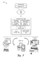
- FIG. 7 illustrates an example system that includes an example computing device that is representative of one or more computing systems and/or devices that may implement the various techniques described herein.
- Latency-based energy storage device selection is described for a device having an energy storage device system with heterogeneous energy storage devices, such as heterogeneous battery cells.
- the heterogeneous energy storage devices include two or more energy storage devices having various different characteristics such as different sizes, capacities, technologies, chemistries, shapes, state of charge (SOC), age, temperature, cycle counts, and so forth. These different characteristics result in different energy storage devices being better suited for different types of operations and scenarios.
- one energy storage device may be a high power density device more efficient at providing larger amounts of energy over shorter amounts of time (e.g., during latency sensitive tasks such as video processing) and another energy storage device may be a high energy density device more efficient at providing smaller amounts of energy over longer amounts of time (e.g., while a device is in a low-power usage or energy saving mode).
- a high power density device charges fast and are capable of supplying a high power output.
- a high energy density device is designed to operate efficiently, but provides lower power output and may be more susceptible to aging and degradation from repeated charge cycles.
- the techniques discussed herein use latency behavior information regarding applications, computing tasks, interaction scenarios and/or past usage of a computing device to assess latency sensitivity of a workload and adjust power draws across multiple heterogeneous energy storage devices. Adjusting the combination of storage devices used for different levels of latency sensitivity as discussed in this document improves performance and efficiency of the energy storage device system both in the short term for handling latency sensitive tasks and over time as individual devices age and cycle counts increase.
- FIG. 1 illustrates an operating environment in accordance with one or more embodiments, generally at 100 .
- the environment 100 includes a computing device 102 having a processing system 104 with one or more processors and devices (e.g., CPUs, GPUs, microcontrollers, hardware elements, fixed logic devices, etc.), one or more computer-readable media 106 , an operating system 108 , and one or more applications 110 that reside on the computer-readable media and which are executable by the processing system.
- the processing system 104 may be configured to include multiple independent processors configured in parallel or in series and one or more multi-core processing units.
- a multi-core processing unit may have two or more processors (“cores”) included on the same chip or integrated circuit.
- the processing system 104 may include multiple processing cores that provide a range of performance capabilities, processing efficiencies, and power usage characteristics.
- the processing system 104 may retrieve and execute computer-program instructions from applications 110 to provide a wide range of functionality to the computing device 102 , including but not limited to gaming, office productivity, email, media management, printing, networking, web-browsing, and so forth.
- applications 110 may also be included, examples of which include game files, office documents, multimedia files, emails, data files, web pages, user profile and/or preference data, and so forth.
- the computing device 102 can be embodied as any suitable computing system and/or device such as, by way of example and not limitation, a gaming system, a desktop computer, a portable computer, a tablet or slate computer, a handheld computer such as a personal digital assistant (PDA), a cell phone, a set-top box, a wearable device (e.g., watch, band, glasses, etc.), and the like.
- a gaming system e.g., a desktop computer, a portable computer, a tablet or slate computer, a handheld computer such as a personal digital assistant (PDA), a cell phone, a set-top box, a wearable device (e.g., watch, band, glasses, etc.), and the like.
- PDA personal digital assistant
- the computing device 102 can be implemented as a television client device 112 , a computer 114 , and/or a gaming system 116 that is connected to a display device 118 to display media content.
- the computing device may be any type of portable computer,
- a computing device may also be configured as a wearable device 124 that is designed to be worn by, attached to, carried by, or otherwise transported by a user.
- wearable devices 124 depicted in FIG. 1 include glasses, a smart band or watch, and a pod device such as clip-on fitness device, media player, or tracker.
- Other examples of wearable devices 124 include but are not limited to badges, a key fob, an access card, and a ring, an article of clothing, a glove, or a bracelet, to name a few examples.
- Any of the computing devices can be implemented with various components, such as one or more processors and memory devices, as well as with any combination of differing components.
- One example of a computing system that can represent various systems and/or devices including the computing device 102 is shown and described below in relation to FIG. 7 .
- the computer-readable media can include, by way of example and not limitation, all forms of volatile and non-volatile memory and/or storage media that are typically associated with a computing device. Such media can include ROM, RAM, flash memory, hard disk, removable media and the like. Computer-readable media can include both “computer-readable storage media” and “communication media,” examples of which can be found in the discussion of the example computing system of FIG. 7 .
- the computing device 102 may also include a power manager 126 that includes or makes use of a latency estimator 127 , and an energy storage device system 128 having multiple heterogeneous energy storage devices that operate as described above and below.
- the power manager 126 represents functionality operable to manage power for the computing device in various ways. For example the power manager 126 may assess system-wide power management considerations and manage availability heterogeneous energy storage devices, processors, and/or processing cores based on the assessment.
- the power manager 126 is configured to implement a switching policy established based on power management considerations to control the battery system 128 . The switching policy depends at least upon latency considerations as discussed herein.
- the latency estimator 127 represents functionality that the power manager may include, invoke, or otherwise make use of to determine latency behavior for a current workload (also referred to herein as usage behavior) of the computing device 102 and manage heterogeneous energy storage devices of the energy storage device system 128 accordingly. This may involve analyzing factors including but not limited to energy storage device characteristics, latency sensitivity of different tasks, application specific latency considerations, estimated or predicted future usage and latency behavior of the computing device 102 , estimated future energy usage of the computing device 102 over a given time period (e.g., a day), and so forth.
- the assessment may further involve analyzing other factors including but not limited to, charge levels/states, the device power state, actual and expected workloads, thermal conditions, user presence, processor/core utilization, application context, device context, priority, contextual clues, and other suitable performance metrics that may be used to drive power management decisions at the system level.
- Different types of applications, tasks, and scenarios may be assigned pre-computed latency sensitivity values that are used by the latency estimator 127 to determine latency behavior for a current workload.
- Latency estimator 127 may additionally operate to estimate or predict latency sensitivity values “on-demand” using the various factors when pre-computed values are not available.
- the power manager 126 is further configured to apply the switching policy to adjust the performance of the battery system 128 based on the assessment of system-wide performance metrics and conditions (e.g., analyzing an operational context for the device), including at least latency sensitivity associated with current workload. Applying the switching policy may involve controlling modes of different energy storage devices (e.g., cells), states of individual energy storage devices and/or availability of heterogeneous energy storage devices included with an energy storage system 128 .
- the power manager 126 is operable to communicate control signals or otherwise interact with the energy storage system 128 to direct operation of switching hardware to switch between heterogeneous battery cells to service the load in accordance with the switching policy and analysis of the operational context.
- the energy storage device system 128 is configured to include multiple heterogeneous energy storage devices. Energy storage devices may be configured in various ways and be implemented in various combinations of as discussed in greater detail below.
- the power manager 126 and energy storage device system 128 may be provided using any suitable combination of hardware, software, firmware, and/or logic devices. As illustrated, the power manager 126 and energy storage device system 128 may be configured as separate, standalone systems. In addition or alternatively, the power manager 126 may also be configured as a system or module that is combined with the operating system 108 or implemented via a controller or other component of the energy storage device system 128 . Details regarding these and other aspects of latency-based energy storage device selection are discussed in the following section.
- the environment 100 further depicts that the computing device 102 may be communicatively coupled via a network 130 to a service provider 132 , which enables the computing device 102 to access and interact with various resources 134 made available by the service provider 132 .
- the resources 134 can include any suitable combination of content and/or services typically made available over a network by one or more service providers.
- content can include various combinations of text, video, ads, audio, multi-media streams, applications, animations, images, webpages, and the like.
- Some examples of services include, but are not limited to, an online computing service (e.g., “cloud” computing), an authentication service, web-based applications, a file storage and collaboration service, a search service, messaging services such as email and/or instant messaging, and a social networking service.
- FIG. 2 depicts generally at 200 example details of a computing device 102 having an energy storage device system 128 with heterogeneous energy storage devices in accordance with one or more implementations.
- Computing device 102 also includes processing system 104 , computer readable media 106 , operating system 108 and applications 110 as discussed in relation to FIG. 1 .
- a power manager 126 is also shown as being implemented as a component of the operating system 108 .
- the energy storage device system 128 is depicted as having energy storage devices 202 and an energy storage device controller 204 .
- the energy storage devices 202 are representative of various different kinds of energy storage devices that may be included with the computing device 102 . These energy storage devices can include, for example, battery cells, supercapacitors, and so forth. It should be noted that these energy storage devices include various devices that store energy as opposed to being an external plug-in AC power source. As mentioned, energy storage devices 202 include energy storage devices having different characteristics such as different sizes/capacities, chemistries, battery technologies, shapes, state of charge (SOC), age, temperature, and so forth (heterogeneous energy storage devices).
- heterogeneous energy storage devices may include either or both of different types of devices designed with different properties and devices having the same or similar properties by design, but having different state characteristics.
- the energy storage device system 128 includes a diverse combination of multiple energy storage devices at least some of which have different characteristics one to another.
- some energy storage devices 202 may be the same and still be part of the energy storage device system 128 (e.g., the energy storage devices 202 may include three battery cells, two of which have the same characteristics and a third of which has one or more characteristics that are different than the first two battery cells).
- energy storage devices may be heterogeneous despite sharing one or more characteristics (e.g., two battery cells may have the same capacities but have different battery technologies and different shapes).
- Various combinations of energy storage devices 202 may be utilized to provide a range of capacities, performance capabilities, efficiencies, and power usage characteristics.
- the energy storage devices 202 include a combination including at least one high energy density device and one high power energy device. This type of combination enables high power delivery in some situations for critical and latency sensitive tasks, and fast charging in other situations to keep the computing device operational and increase overall battery life.
- high power density devices are more efficient at providing larger amounts of energy over shorter amounts of time (e.g., during latency sensitive tasks such as video processing).
- the high power density devices may charge fast and provide high power output.
- high energy density devices are designed to operate efficiently and may have larger capacities. However, the high energy density devices supply less power and may not be suitable for latency sensitive tasks.
- the high energy density devices are more susceptible to increases cycle counts, which can accelerate aging and degradation over time.
- Situationally selecting an appropriate combination of different batteries to use, charge, and drain in accordance with techniques described herein enables increase performance and more efficient use of the energy storage device system 128 . Additionally, cycle counts can be controlled and balanced to avoid having some energy storage devices 202 age much faster than other energy storage devices 202 .
- a bulk of the power can be supplied via high power density device, which enables support for greater processing performance without adversely affecting the cycle count and lifetime of the high energy density devices.
- the energy storage device controller 204 is representative of a control system to control operation of the energy storage device system 128 and delivery of power from the energy storage devices 202 to service a system load of the computing device 102 .
- the system load refers to the energy required by the computing device 102 at any given point in time in order to operate.
- the energy storage device controller 204 may be configured using various logic, hardware, circuitry, firmware, and/or software suitable to connect the energy storage devices 202 one to another, supply power to the system, switch between the energy storage devices, and so forth.
- the energy storage device controller 204 in FIG. 2 is depicted as including switching hardware 206 and control logic 208 that is operable to selectively switch between different designated energy storage devices 202 at different times.
- Control logic 208 may reflect different switching modes that switch between drawing power from different ones of the energy storage devices 202 so that power is drawn from energy storage devices 202 in accordance with a particular power ratio as determined by the power manager 126 .
- switching hardware 206 can be utilized to set-up a switching scheme to select different energy storage devices based on different factors and workload patterns for the computing device 102 .
- control logic 208 may reflect different switching modes that switch between providing power to different energy storage devices 202 to charge energy storage devices 202 in accordance with a particular power ratio as determined by the power manager 126 .
- charging and discharging modes depend at least in part upon latency considerations as discussed herein.
- selection of an energy storage device 202 occurs under the influence of the power manager 126 .
- the power manager 126 represents functionality operable to manage the energy storage devices 202 and makes policy decisions regarding how to charge and discharge the device according to various criteria.
- the selection of an energy storage device 202 refers to selection of a particular one or more of the energy storage devices 202 and an amount of power that is to be drawn from each of the selected one or more energy storage devices. This selection of the amount of power that is to be drawn can be identified by a power ratio of one energy storage device to another. A power ratio of x.y can be used, where x refers to power drawn from a first energy storage device and y refers to power drawn from a second energy storage device.
- a power ratio of 4:1 indicates that four times the amount of power is to be drawn from the first energy storage device than from the second energy storage device.
- Similar power ratios can be used in situations in which there are three or more energy storage devices, such as a power ratio x1:x2: . . . :xm, where x1 refers to power drawn from a first energy storage device, x2 refers to power drawn from a second energy storage device, and xm refers to power drawn from an mth energy storage device.
- a power ratio of 4:2:1:1 indicates that: the amount of power to be drawn from the first energy storage device is twice the amount of power to be drawn from the second energy storage device and four times the amount of power to be drawn from each of the third and fourth energy storage devices, the amount of power to be drawn from the second energy storage device is twice the amount of power to be drawn from each of the third and fourth energy storage devices, and the amount of power to be drawn from the third energy storage device is the same as the amount of power to be drawn from the fourth energy storage device.
- the selection of an energy storage device 202 and setting of power ratio is based at least in part upon latency considerations.
- Functionality to assess latency behavior for tasks, applications, and workloads is represented by the latency estimator 127 , which the power manager 126 may rely upon to inform power management decisions.
- the latency behavior assessment involves identifying latency sensitive tasks, applications, and workloads that benefit from higher power and processing frequencies (e.g., a high power mode). The assessment may also be based upon the priority assigned to tasks and the current state of the energy storage device system.
- latency sensitivity is determined to exceed an established threshold associated with a “high” level of sensitivity, the power manager 126 is configured to favor use of high power density devices over high energy density device to increase performance (e.g., reduce latency).
- the power manager 126 is configured to favor use of high energy density devices over high power density devices to conserve charge and availability of the high power density devices.
- a table, list, file or other suitable data structure that correlates different tasks, applications, and scenarios to latency sensitivity is compiled and maintained via the latency estimator 127 .
- This latency data is used to assess the latency for a particular workload over a period time (e.g., an epoch) based on the set of tasks, applications, scenarios, etc. corresponding to the workload.
- a period time e.g., an epoch
- latency data can be used to look-up sensitivity for individual applications/tasks listed in the latency data and make an overall determination regarding the degree to which the current workload is latency sensitive.
- the latency estimator 127 may operate to predict the latency sensitivity for such items. Information regarding sensitivity that is predicted may be used to update the listed tasks/applications. The predictions may be based on similarity to known items. For example, different applications of the same class (e.g., video players, image editors, desktop productivity apps, email clients, etc.) may be assigned similar values with respect to latency based on similarity. Additionally, the latency estimator 127 may also consider the processing context to predict whether items may benefit from higher processing performance or not. For example, if an application is network bandwidth or I/O bottlenecked then increasing power is unlikely to have a substantial effect.
- the computing device is operating with low power and the processing system is at or near the applicable power cap, there may be room to increase performance by favoring high power energy density devices.
- information regarding latency sensitivity may be available through a service via a service provider 132 .
- the data structure that correlates different tasks, applications, and scenarios to latency sensitivity may be obtained and updated through interaction with the service.
- Various other techniques to assess latency sensitivity are also contemplated.
- the power manager 126 operates to make power management decisions based as least in part upon the latency assessments as just described. Although this document focuses on latency-based decisions and selections, power management decisions may also depend upon other factors including but not limited to predicted energy consumption, expected usage of the computing device, availability of charging opportunities, user behavior and schedules, geographic location, and characteristics of the energy storage device systems and individual devices, to name a few examples. Such additional factors may be employed in combination with latency considerations and also in connection with non-latency sensitive workloads to control both charging and discharging of the system of heterogeneous energy storage devices.
- the power manager 126 uses predicted latency as determined by the latency estimator 127 , alone or in combination with other factors, to select an appropriate combination of energy storage devices to service the current workload and direct changes to switching hardware 206 to use the selected combination. For example, the power manager 126 may communicate control signals or other suitable data that is interpreted and applied by the control logic 208 to operate switching hardware 206 to draw power as specified by the power manager 126 for a given time frame or epoch. In one or more implementations, selection of the combination of energy storage devices involves setting a power ratio for drawing power from the energy storage device 202 to control the division of the power load among the energy storage devices. This power ratio is used by the control logic 208 to determine which energy storage device(s) to draw power from at any given time.
- the power ratio may reflect decimal or fractional values for the division of the power.
- the power ratio may also be expressed as amounts of power draw (e.g., number of watts) for each individual device.
- a number of modes corresponding to different ratios may be established and the mode may be selected based upon the latency assessment.
- the power manager 126 may include or otherwise make use of a power ratio estimator module 210 and power ratio data 212 .
- the power ratio estimator module 210 represents functionality operable to use the information gathered and generated by power manager 126 to determine the ratios in which power is to be drawn from the various energy storage devices in the energy storage device system 128 .
- the power ratio estimator module 210 determines ratios to utilize for a period of time (e.g., epoch) based at least upon predicted latency sensitivity during the period of time. Such determinations can be made by the power ratio estimator module 210 at various regular or irregular intervals. For example, the power ratio estimator module 210 can make this determination every minute or second, after the amount of time in a current epoch elapses (e.g., at the beginning of each epoch), and so forth.
- the power ratio data 212 represents data used by the power ratio estimator module 210 .
- the power ratio data 212 can be implemented as any of a variety of different data structures (e.g., a table, list, or other record), or as any of a variety of different formulas, rules, algorithms, and so forth.
- the power ratio specifies a division of an overall power load between different energy storage devices. This may be expressed in terms of percentage loads, amounts of power draw, time factors, or otherwise.
- the power ratio data 218 is a table of threshold values for latency and corresponding power ratios.
- the power ratio estimator module 210 accesses the power ratio data 212 , compares the combined estimated latency to the threshold values in the power ratio data 212 , and sets the power ratio for the computing device as the power ratio corresponding to the threshold values.
- Table I illustrates an example table that can be used as power ratio data 218 . It should be noted that the table illustrated in Table I is an example, and that other data structures, formulas, algorithms, and so forth can be used.
- an energy storage device system 128 having multiple diverse energy storage devices may be configured in various ways and employ a variety of different types of energy storage devices.
- different energy storage devices 202 included with a system have different characteristics, such as differences in one or more of battery chemistry, capacity, voltage, size, shapes and/or state of charge (SOC), to name a few examples.
- SOC state of charge
- Using different types of energy storage devices provides flexibility for design of the energy storage device system and circuit boards, and consequently enables device developers to make better utilization of internal space to provide devices having increased battery life and efficiency.
- the different energy storage devices are arranged in a circuit that enables selective switching among the energy storage devices.
- FIG. 3 depicts generally at 300 one illustrative example arrangement of an energy storage device system 128 having multiple energy storage devices 202 that are battery cells.
- the energy storage devices 202 may be connected in a circuit that includes an energy storage device controller 204 that implements switching hardware 206 and control logic 208 to switch back and forth among the energy storage devices 202 .
- Each of the energy storage devices 202 may be represented according to a battery model 302 an example of which is depicted in FIG. 3 .
- Each of the battery cells may also be coupled to a capacitor buffer 304 , which is provided to smooth out the supplied power when the switching hardware 206 is employed to switch between cells.
- a battery model 302 is shown in FIG. 3 , it is to be appreciated that the concepts described herein are not limited to a particular model and various different models may be utilized, individually or in combination.
- multiple energy storage devices 202 are arranged together with switching hardware 206 that enables switching between the energy storage devices.
- the switching circuit may also include a mechanism to smooth the current draw from different energy storage devices, such as the example capacitor buffer 304 or other smoothing components.
- the switching circuit includes control logic 208 or comparable functionality to designate and control which of the energy storage devices are used to service the load, the mode of operation of the energy storage devices, and the amount of power that is drawn from each energy storage device.
- the control logic 208 controls the amount of power that is drawn from each energy storage device in accordance with the power ratio determined by the schedule-based energy storage device selection system 126 .
- the switching hardware 206 is controlled to cycle rapidly between two or more different energy storage devices to draw a percentage of the overall load current from each energy storage device.
- the switching hardware 206 is cycled at a relatively high frequency to pull current from different energy storage devices according to the determined power ratio. Effectively, the rapid cycling in this mode enables servicing of the load by drawing different portions of load current from different cells at the same time. For example, for an energy storage device system having three cells and a determined power ratio of 7:2:1, seventy percent of the load may be drawn from a first energy storage device, twenty percent from a second energy storage device, and ten percent from a third energy storage device.
- FIG. 3 further depicts an equivalent circuit model 306 for the energy storage device system 128 .
- the equivalent circuit model 306 represents switching hardware 206 that can be used to provide current I to a load 308 using an arrangement of multiple battery energy storage devices 202 .
- four different battery cells 310 ( 1 )- 310 ( 4 ) are connectable to the load 308 via a switch 312 .
- the switch 312 may be implemented as a solid state switch or other suitable hardware switching device.
- the example battery cells 310 ( 1 )- 310 ( 4 ) represent different heterogeneous batteries configured to provide respective amounts of current I 1 , I 2 , I 3 , and I 4 .
- Portions of current obtained from each cell may be specified in various ways such as by associating percentages, weight factors, thresholds, or designated amounts with the cells.
- the operating system 108 may make policy decisions such as mode selection and energy storage device constraints setting for energy storage device switching. Policy decisions are made based upon performance parameters indicative of an operational context including at least information regarding battery states and characteristics obtained from the battery controller 204 . As represented, policy decisions may be made under the influence of a latency estimator 127 that determines and supplies information regarding latency sensitivity of tasks, applications, workloads, and interaction scenarios.
- the API 406 provides a mechanism by which control signals are communicated to the energy storage device controller 204 to set the registers 404 in accordance with the policy decisions.
- Latency behavior of computing tasks performed via a computing device having multiple heterogeneous energy storage devices over a period of time is predicted (block 502 ).
- the latency behavior of tasks associated with the workload can be predicted in various ways as discussed above.
- the latency behavior can be determined, for example, based on an assessment of applications, tasks, and interaction scenarios that are currently being performed and/or are expected to be performed during a time period. This may involve analyzing applications that are launched and corresponding tasks associated with the applications.
- a data structure that correlates different items e.g., applications, tasks, workloads, scenarios, etc.
- latency sensitivity values may be refereed to look-up applicable values.
- a combination of energy storage devices to use for performance of the computing tasks is selected in dependence upon the predicted latency (block 504 ). For example, batteries or energy devices that are better suited to the particular level of latency sensitivity determined for the tasks may be selected or favored based on the analysis. As noted, higher power density devices may be favored in latency sensitive scenarios and higher energy density devices may be favored in situation that are not deemed latency sensitive. Power draws between available energy storage devices are adjusted according to the latency sensitive levels determined for the time period.
- a power manager 126 may operate to direct operation of an energy storage device controller 204 to implement policy decisions as previously discussed. In at least some implementations, this involves communications between the power manager 126 and energy storage device controller 204 effective to control switching hardware to draw levels of power for different energy storage devices as specified by the power manager. For example, different energy storage devices may be activated and deactivated based on determined policy settings. The policy settings are based at least partially upon latency considerations as described herein. In addition or alternatively, policy settings may specify power ratios that are mapped to the predicted latency behavior as described previously.
- the policy settings may be configured to cause implementation of different pre-established operating modes such as a high power mode, balanced mode, or low power mode.
- power draws for different energy storage devices are specified by the selected mode. Accordingly, adjustments to power draws based on latency considerations may be made in various example ways enumerated as well as using other suitable techniques to change power draws for a set of heterogeneous energy storage devices in dependence upon assessments of latency behavior for computing tasks.
- FIG. 6 is a flow diagram that describes details of another example procedure 600 for latency-based energy storage device selection in accordance with one or more implementations.
- the procedure 600 describes details of adjusting power draw between multiple heterogeneous energy storage device including high power density devices and high energy density device.
- the procedure 600 can be implemented by way of a suitably configured computing device, such as by way of an operating system 108 , power manager 126 , and/or other functionality described in relation to the examples of FIGS. 1-4 .
- the determination is made in relation to a computing device including an energy storage device system with at least one high power density device and at least one high energy density device (block 602 ).
- latency sensitivity of a workload can be determined in various ways as discussed herein including using preset values or predicting latency sensitivity on demand. In one example, the determination is performed by comparing items associated with the workload to items contained in a data structure that correlates different tasks, applications, and scenarios to levels of latency sensitivity to assess latency sensitivity of the workload.
- different threshold levels of latency sensitivity can be established and related to power management settings, such as power ratios or modes of operation as noted in this description.
- threshold levels for latency sensitivity may be correlated to different power ratios as represented and discussed in relation to Table 1 above. Accordingly, different determined levels of latency sensitivity may trigger different corresponding responses to adjust power draws between heterogeneous energy storage devices of an energy storage device system.
- conclusion of latency sensitive tasks associated with the workload is recognized (block 606 ).
- the system recognizes that the particular tasks and/or interaction with applications that causes the elevated level of latency sensitivity are completed. Because of this, a corresponding drop in the level of latency sensitivity occurs and the system is able to detect this drop.
- FIG. 7 illustrates an example system 700 that includes an example computing device 702 that is representative of one or more computing systems and/or devices that may implement the various techniques described herein.
- the computing device 702 may be, for example, a server of a service provider, a device associated with a client (e.g., a client device), an on-chip system, and/or any other suitable computing device or computing system.
- the example computing device 702 as illustrated includes a processing system 704 , one or more computer-readable media 706 , and one or more I/O interfaces 708 that are communicatively coupled, one to another.
- the computing device 702 may further include a system bus or other data and command transfer system that couples the various components, one to another.
- a system bus can include any one or combination of different bus structures, such as a memory bus or memory controller, a peripheral bus, a universal serial bus, and/or a processor or local bus that utilizes any of a variety of bus architectures.
- a variety of other examples are also contemplated, such as control and data lines.
- the processing system 704 is representative of functionality to perform one or more operations using hardware. Accordingly, the processing system 704 is illustrated as including hardware elements 710 that may be configured as processors, functional blocks, and so forth. This may include implementation in hardware as an application specific integrated circuit or other logic device formed using one or more semiconductors.
- the hardware elements 710 are not limited by the materials from which they are formed or the processing mechanisms employed therein.
- processors may be comprised of semiconductor(s) and/or transistors (e.g., electronic integrated circuits (ICs)).
- processor-executable instructions may be electronically-executable instructions.
- the computer-readable media 706 is illustrated as including memory/storage 712 .
- the memory/storage 712 represents memory/storage capacity associated with one or more computer-readable media.
- the memory/storage 712 may include volatile media (such as random access memory (RAM)) and/or nonvolatile media (such as read only memory (ROM), Flash memory, optical disks, magnetic disks, and so forth).
- RAM random access memory
- ROM read only memory
- Flash memory optical disks
- magnetic disks magnetic disks, and so forth
- the memory/storage 712 may include fixed media (e.g., RAM, ROM, a fixed hard drive, and so on) as well as removable media (e.g., Flash memory, a removable hard drive, an optical disc, and so forth).
- the computer-readable media 706 may be configured in a variety of other ways as further described below.
- Input/output interface(s) 708 are representative of functionality to allow a user to enter commands and information to computing device 702 , and also allow information to be presented to the user and/or other components or devices using various input/output devices.
- input devices include a keyboard, a cursor control device (e.g., a mouse), a microphone for voice operations, a scanner, touch functionality (e.g., capacitive or other sensors that are configured to detect physical touch), a camera (e.g., which may employ visible or non-visible wavelengths such as infrared frequencies to detect movement that does not involve touch as gestures), and so forth.
- Examples of output devices include a display device (e.g., a monitor or projector), speakers, a printer, a network card, tactile-response device, and so forth.
- the computing device 702 may be configured in a variety of ways as further described below to support user interaction.
- modules include routines, programs, objects, elements, components, data structures, and so forth that perform particular tasks or implement particular abstract data types.
- module generally represent software, firmware, hardware, or a combination thereof.
- the features of the techniques described herein are platform-independent, meaning that the techniques may be implemented on a variety of commercial computing platforms having a variety of processors.
- Computer-readable media may include a variety of media that may be accessed by the computing device 702 .
- computer-readable media may include “computer-readable storage media” and “communication media.”
- Computer-readable storage media refers to media and/or devices that enable storage of information in contrast to mere signal transmission, carrier waves, or signals per se. Computer-readable storage media does not include signal bearing media, transitory signals, or signals per se.
- the computer-readable storage media includes hardware such as volatile and non-volatile, removable and non-removable media and/or storage devices implemented in a method or technology suitable for storage of information such as computer readable instructions, data structures, program modules, logic elements/circuits, or other data.
- Examples of computer-readable storage media may include, but are not limited to, RAM, ROM, EEPROM, flash memory or other memory technology, CD-ROM, digital versatile disks (DVD) or other optical storage, hard disks, magnetic cassettes, magnetic tape, magnetic disk storage or other magnetic storage devices, or other storage device, tangible media, or article of manufacture suitable to store the desired information and which may be accessed by a computer.
- Communication media may refer to signal-bearing media that is configured to transmit instructions to the hardware of the computing device 702 , such as via a network.
- Communication media typically may embody computer readable instructions, data structures, program modules, or other data in a modulated data signal, such as carrier waves, data signals, or other transport mechanism.
- Communication media also include any information delivery media.
- modulated data signal means a signal that has one or more of its characteristics set or changed in such a manner as to encode information in the signal.
- communication media include wired media such as a wired network or direct-wired connection, and wireless media such as acoustic, RF, infrared, and other wireless media.
- hardware elements 710 and computer-readable media 706 are representative of instructions, modules, programmable device logic and/or fixed device logic implemented in a hardware form that may be employed in some embodiments to implement at least some aspects of the techniques described herein.
- Hardware elements may include components of an integrated circuit or on-chip system, an application-specific integrated circuit (ASIC), a field-programmable gate array (FPGA), a complex programmable logic device (CPLD), and other implementations in silicon or other hardware devices.
- ASIC application-specific integrated circuit
- FPGA field-programmable gate array
- CPLD complex programmable logic device
- a hardware element may operate as a processing device that performs program tasks defined by instructions, modules, and/or logic embodied by the hardware element as well as a hardware device utilized to store instructions for execution, e.g., the computer-readable storage media described previously.
- software, hardware, or program modules including the operating system 108 , applications 110 , power manager 126 , and other program modules may be implemented as one or more instructions and/or logic embodied on some form of computer-readable storage media and/or by one or more hardware elements 710 .
- the computing device 702 may be configured to implement particular instructions and/or functions corresponding to the software and/or hardware modules. Accordingly, implementation of modules as a module that is executable by the computing device 702 as software may be achieved at least partially in hardware, e.g., through use of computer-readable storage media and/or hardware elements 710 of the processing system.
- the instructions and/or functions may be executable/operable by one or more articles of manufacture (for example, one or more computing devices 702 and/or processing systems 704 ) to implement techniques, modules, and examples described herein.
- the example system 700 enables ubiquitous environments for a seamless user experience when running applications on a personal computer (PC), a television device, and/or a mobile device. Services and applications run substantially similar in all three environments for a common user experience when transitioning from one device to the next while utilizing an application, playing a video game, watching a video, and so on.
- PC personal computer
- television device a television device
- mobile device a mobile device. Services and applications run substantially similar in all three environments for a common user experience when transitioning from one device to the next while utilizing an application, playing a video game, watching a video, and so on.
- multiple devices are interconnected through a central computing device.
- the central computing device may be local to the multiple devices or may be located remotely from the multiple devices.
- the central computing device may be a cloud of one or more server computers that are connected to the multiple devices through a network, the Internet, or other data communication link.
- this interconnection architecture enables functionality to be delivered across multiple devices to provide a common and seamless experience to a user of the multiple devices.
- Each of the multiple devices may have different physical requirements and capabilities, and the central computing device uses a platform to enable the delivery of an experience to the device that is both tailored to the device and yet common to all devices.
- a class of target devices is created and experiences are tailored to the generic class of devices.
- a class of devices may be defined by physical features, types of usage, or other common characteristics of the devices.
- the computing device 702 may assume a variety of different configurations, such as for computer 714 , mobile 716 , and television 718 uses. Each of these configurations includes devices that may have generally different constructs and capabilities, and thus the computing device 702 may be configured according to one or more of the different device classes. For instance, the computing device 702 may be implemented as the computer 714 class of a device that includes a personal computer, desktop computer, a multi-screen computer, laptop computer, netbook, and so on.
- the computing device 702 may also be implemented as the mobile 716 class of device that includes mobile devices, such as a mobile phone, portable music player, portable gaming device, a tablet computer, a multi-screen computer, and so on.
- the computing device 702 may also be implemented as the television 718 class of device that includes devices having or connected to generally larger screens in casual viewing environments. These devices include televisions, set-top boxes, gaming consoles, and so on.
- the techniques described herein may be supported by these various configurations of the computing device 702 and are not limited to the specific examples of the techniques described herein. This is illustrated through inclusion of the power manager 126 and the energy storage device system 128 on the computing device 702 .
- the functionality represented by power manager 126 and other modules/applications may also be implemented all or in part through use of a distributed system, such as over a “cloud” 720 via a platform 722 as described below.
- the cloud 720 includes and/or is representative of a platform 722 for resources 724 .
- the platform 722 abstracts underlying functionality of hardware (e.g., servers) and software resources of the cloud 720 .
- the resources 724 may include applications and/or data that can be utilized while computer processing is executed on servers that are remote from the computing device 702 .
- Resources 724 can also include services provided over the Internet and/or through a subscriber network, such as a cellular or Wi-Fi network.
- the platform 722 may abstract resources and functions to connect the computing device 702 with other computing devices.
- the platform 722 may also serve to abstract scaling of resources to provide a corresponding level of scale to encountered demand for the resources 724 that are implemented via the platform 722 .
- implementation of functionality described herein may be distributed throughout the system 700 .
- the functionality may be implemented in part on the computing device 702 as well as via the platform 722 that abstracts the functionality of the cloud 720 .
- Example implementations of techniques described herein include, but are not limited to, one or any combinations of one or more of the following examples:
- a method implemented by a computing device having multiple heterogeneous energy storage devices comprising: predicting latency behavior of computing tasks performed via the computing device for a period of time; selecting a combination of energy storage devices to use for performance of the computing tasks in dependence upon the predicted latency behavior; and causing adjustments to switching hardware to supply power for performance of the computing tasks from the selected combination of energy storage devices during the period of time.
- predicting the latency behavior includes assessing latency sensitivity of individual computing tasks associated with a workload for the period of time and establishing overall latency sensitivity for the period of time based on the latency sensitivity for the individual computing tasks.
- predicting the latency behavior includes determining latency sensitivity associated with applications executing on the computing device for the period of time.
- predicting the latency behavior comprises referencing a data structure configured to correlate different computing tasks and applications to corresponding levels of latency sensitivity.
- selecting the combination of energy storage devices comprises: comparing predicted latency behavior to one or more defined threshold levels of latency sensitivity; determining a threshold level that corresponds to the predicted latency behavior; and setting a division of an overall power load between the multiple heterogeneous energy storage devices as designated for the threshold level that corresponds to the predicted latency behavior
- causing adjustments to switching hardware comprises setting a power ratio for an energy storage system including the multiple heterogeneous energy storage devices to control power draw from the multiple heterogeneous energy storage devices as designated for the predicted latency behavior.
- the multiple heterogeneous energy storage devices include at least one high power density device and at least one high energy density device; and selecting the combination comprises balancing a division of power draw between the high power density device and the high energy density device based on the predicted latency behavior.
- causing adjustments to switching hardware comprises communicating control signals to a controller for an energy storage system including the multiple heterogeneous energy storage devices and the switching hardware to direct operation of switching hardware to draw power from the selected combination of energy storage devices.
- control signals are configured to designate a switching mode for the multiple heterogeneous energy storage devices based on the predicted latency behavior.
- a computing device comprising: an energy storage device system including multiple heterogeneous energy storage devices; and a power manager configured to direct operations of the energy storage device system to control power draw from the multiple heterogeneous energy storage devices based at least in part upon an assessment of latency sensitivity of a workload performed via the computing device for a period of time, including: causing a division of power draw between the multiple heterogeneous energy storage devices to favor high power density devices included with the multiple heterogeneous energy storage devices to reduce latency when latency sensitivity is at levels designated as high; and causing the division of power draw between the multiple heterogeneous energy storage devices to favor high energy density devices included with the multiple heterogeneous energy storage devices to conserve power for future workloads when latency sensitivity is below the levels designated as high.
- causing the division of power comprises: determining a power ratio based upon the assessment of latency sensitivity; and communicating the determined power ratio for use by the energy storage device system, thereby directing operation of switching hardware of the energy storage device system to apply the power ratio to implement the corresponding division of power draw.
- the power manager includes a latency estimator configured to perform the assessment of latency sensitivity for the workload including analyzing one or more of energy storage device characteristics, latency sensitivity of different tasks, application-specific latency considerations, estimated device usage, or estimated energy usage to predict latency sensitivity for the workload.
- the latency estimator is further configured to select a combination of energy storage devices to use for performance of the workload in dependence upon the predicted latency sensitivity, the division of power draw corresponding to the combination of energy storage devices that is selected.
- the power manager includes a power ratio estimator configured to derive a power ratio that specifies the division of power draw based upon the assessment of latency sensitivity.
- a computing device comprising: an energy storage device system with multiple heterogeneous energy storage devices including at least on high power density device and at least one high energy density device; one or more processors; and one or more computer-readable storage media having stored thereon instructions that, responsive to execution by the one or more processors, cause the one or more processors to perform operations including: determining that latency sensitivity of a workload for the computing device exceeds a threshold associated with high latency sensitivity; and responsive to determining that latency sensitivity exceeds the threshold, adjusting a power ratio for the energy storage device system to increase a percentage of power to service the workload supplied from the high power density device.
- the computing device as described in any one or more of the examples in this section, wherein the instructions further cause the one or more processors to perform operations including: recognizing conclusion of latency sensitive tasks associated with the work load; and responsive to recognizing conclusion of the latency sensitive tasks, readjusting the power ratio to divide power supply from the energy storage device system according to factors designated for non-latency sensitive workloads.
- the computing device as described in any one or more of the examples in this section, wherein the factors designated for non-latency sensitive workloads include one or more of predicted energy consumption, expected usage of the computing device, availability of charging opportunities, user behavior and schedules, geographic location, or characteristics of the energy storage device system.
- the computing device as described in any one or more of the examples in this section, wherein the instructions further cause the one or more processors to perform operations including: determining latency sensitivity of the workload by comparing items associated with the workload to items contained in a data structure that correlates different tasks, applications, and scenarios to levels of latency sensitivity.
Abstract
Description
| TABLE I | |||
| Latency Sensitivity Value | Power Ratio | ||
| Below | | ||
| Between | | ||
| Above | | ||
Thus, as shown in Table I, three different power ratios are available, depending on the combined latency sensitivity. Although only three power ratios and two threshold values (
Claims (20)
Priority Applications (3)
| Application Number | Priority Date | Filing Date | Title |
|---|---|---|---|
| US14/941,416 US9939862B2 (en) | 2015-11-13 | 2015-11-13 | Latency-based energy storage device selection |
| PCT/US2016/060415 WO2017083170A1 (en) | 2015-11-13 | 2016-11-04 | Latency-based energy storage device selection |
| US15/944,500 US20190107875A1 (en) | 2015-11-13 | 2018-04-03 | Latency-Based Energy Storage Device Selection |
Applications Claiming Priority (1)
| Application Number | Priority Date | Filing Date | Title |
|---|---|---|---|
| US14/941,416 US9939862B2 (en) | 2015-11-13 | 2015-11-13 | Latency-based energy storage device selection |
Related Child Applications (1)
| Application Number | Title | Priority Date | Filing Date |
|---|---|---|---|
| US15/944,500 Continuation US20190107875A1 (en) | 2015-11-13 | 2018-04-03 | Latency-Based Energy Storage Device Selection |
Publications (2)
| Publication Number | Publication Date |
|---|---|
| US20170139465A1 US20170139465A1 (en) | 2017-05-18 |
| US9939862B2 true US9939862B2 (en) | 2018-04-10 |
Family
ID=57485859
Family Applications (2)
| Application Number | Title | Priority Date | Filing Date |
|---|---|---|---|
| US14/941,416 Active 2035-12-02 US9939862B2 (en) | 2015-11-13 | 2015-11-13 | Latency-based energy storage device selection |
| US15/944,500 Abandoned US20190107875A1 (en) | 2015-11-13 | 2018-04-03 | Latency-Based Energy Storage Device Selection |
Family Applications After (1)
| Application Number | Title | Priority Date | Filing Date |
|---|---|---|---|
| US15/944,500 Abandoned US20190107875A1 (en) | 2015-11-13 | 2018-04-03 | Latency-Based Energy Storage Device Selection |
Country Status (2)
| Country | Link |
|---|---|
| US (2) | US9939862B2 (en) |
| WO (1) | WO2017083170A1 (en) |
Cited By (5)
| Publication number | Priority date | Publication date | Assignee | Title |
|---|---|---|---|---|
| US20170317493A1 (en) * | 2015-02-26 | 2017-11-02 | Microsoft Technology Licensing, Llc | Load Allocation for Multi-Battery Devices |
| US10061366B2 (en) | 2015-11-17 | 2018-08-28 | Microsoft Technology Licensing, Llc | Schedule-based energy storage device selection |
| US10158148B2 (en) | 2015-02-18 | 2018-12-18 | Microsoft Technology Licensing, Llc | Dynamically changing internal state of a battery |
| US10228747B2 (en) | 2015-02-09 | 2019-03-12 | Microsoft Technology Licensing, Llc | Battery parameter-based power management for suppressing power spikes |
| US10992156B2 (en) * | 2017-10-17 | 2021-04-27 | The Board Of Trustees Of The Leland Stanford Junior University | Autonomous screening and optimization of battery formation and cycling procedures |
Families Citing this family (5)
| Publication number | Priority date | Publication date | Assignee | Title |
|---|---|---|---|---|
| US9793570B2 (en) | 2015-12-04 | 2017-10-17 | Microsoft Technology Licensing, Llc | Shared electrode battery |
| US10917496B2 (en) * | 2017-09-05 | 2021-02-09 | Amazon Technologies, Inc. | Networked storage architecture |
| US11533272B1 (en) * | 2018-02-06 | 2022-12-20 | Amesite Inc. | Computer based education methods and apparatus |
| US10963362B2 (en) * | 2019-04-11 | 2021-03-30 | Dell Products L.P. | Method and system for identifying latency-sensitive computing workloads of information handling systems |
| CN115934002B (en) * | 2023-03-08 | 2023-08-04 | 阿里巴巴(中国)有限公司 | Solid state disk access method, solid state disk, storage system and cloud server |
Citations (275)
| Publication number | Priority date | Publication date | Assignee | Title |
|---|---|---|---|---|
| US4145669A (en) | 1977-02-10 | 1979-03-20 | Westinghouse Electric Corp. | Cathode electrode configuration for gas laser system |
| JPH0410366A (en) | 1990-04-25 | 1992-01-14 | Otsuka Chem Co Ltd | Secondary battery having heating mechanism |
| US5091819A (en) | 1987-06-30 | 1992-02-25 | Jens Christiansen | Gas-electronic switch (pseudospark switch) |
| WO1994001914A1 (en) | 1992-07-08 | 1994-01-20 | Benchmarq Microelectronics, Inc. | Method and apparatus for monitoring battery capacity with charge control |
| JPH0684544A (en) | 1992-09-01 | 1994-03-25 | Nippondenso Co Ltd | Lithium secondary battery |
| US5315228A (en) | 1992-01-24 | 1994-05-24 | Compaq Computer Corp. | Battery charge monitor and fuel gauge |
| US5519261A (en) | 1991-02-14 | 1996-05-21 | Dell U.S.A., L.P. | Power management control system for battery powered devices |
| US5543245A (en) | 1993-03-15 | 1996-08-06 | Alcatel Converters | System and method for monitoring battery aging |
| US5614332A (en) | 1995-05-26 | 1997-03-25 | Pavelle; Richard | Method and apparatus for increasing charging and discharging efficiency in batteries |
| US5684404A (en) | 1995-11-17 | 1997-11-04 | Sharp Microelectronics Technology, Inc. | System and method of measuring a battery lifetime |
| US5691742A (en) | 1995-05-24 | 1997-11-25 | Dell U.S.A., L.P. | Software battery gauge for portable computers |
| US5693010A (en) | 1994-03-30 | 1997-12-02 | Alza Corporation | Reduction of skin irritation during electrotransport delivery |
| US5705929A (en) | 1995-05-23 | 1998-01-06 | Fibercorp. Inc. | Battery capacity monitoring system |
| US5764032A (en) | 1997-03-06 | 1998-06-09 | Maxim Integrated Products, Inc. | Multiple battery switchover circuits |
| US5818200A (en) | 1997-05-06 | 1998-10-06 | Dell U.S.A., L.P. | Dual smart battery detection system and method for portable computers |
| US5894212A (en) | 1997-09-19 | 1999-04-13 | Tarrytown Consulting, Inc. | Discharge monitoring and isolating system for batteries |
| US5914585A (en) | 1996-02-20 | 1999-06-22 | Norand Corporation | Power sharing in computing systems with a plurality of electronic devices |
| WO1999033124A1 (en) | 1997-12-23 | 1999-07-01 | Telefonaktiebolaget Lm Ericsson | A portable electronic apparatus, with battery supplied components |
| US5963010A (en) | 1996-10-31 | 1999-10-05 | Hitachi, Ltd. | Battery controller for controlling batteries of different kinds and including battery monitoring means for calculating remaining operation time and an information processing apparatus including such battery controller |
| US6139987A (en) | 1997-12-27 | 2000-10-31 | Agency For Defense Development | Bipolar battery |
| US6154012A (en) | 1999-10-13 | 2000-11-28 | Xicor, Inc. | Gas gauge implementation |
| US6252511B1 (en) | 1997-06-20 | 2001-06-26 | Compaq Computer Corporation | Real-time battery gauge display |
| US6258473B1 (en) | 1997-04-04 | 2001-07-10 | Wilson Greatbatch Ltd. | Electrochemical cell having multiplate electrodes with differing discharge rate regions |
| US6268711B1 (en) | 1999-05-05 | 2001-07-31 | Texas Instruments Incorporated | Battery manager |
| US20010010456A1 (en) | 2000-01-27 | 2001-08-02 | Osamu Kaite | Method of charging a plurality of batteries |
| US20010013767A1 (en) | 2000-02-14 | 2001-08-16 | Tsuyoshi Takemoto | Discharge circuit and duty ratio setting method |
| US6299998B1 (en) | 1999-03-15 | 2001-10-09 | Reveo, Inc. | Movable anode fuel cell battery |
| US20010044332A1 (en) | 2000-05-19 | 2001-11-22 | Fujitsu Limited | Information device, power-saving-mode switching method, and recording medium storing power-saving-mode switching program |
| US6346794B1 (en) | 1999-06-08 | 2002-02-12 | International Business Machines Corporation | Method of controlling charge and discharge of a plurality of batteries |
| US6353304B1 (en) | 2001-01-19 | 2002-03-05 | Sandia Corporation | Optimal management of batteries in electric systems |
| US6417646B1 (en) | 2001-05-22 | 2002-07-09 | Honeywell International Inc. | Circuit for monitoring cells of a multi-cell battery during charge |
| US6463495B1 (en) | 1999-03-29 | 2002-10-08 | Compaq Information Technologies Group, L.P. | Command and control infrastructure for a computer system using the computer's power rail |
| US20020155327A1 (en) | 2001-04-24 | 2002-10-24 | Faris Sadeg M. | Hybrid electrochemical cell system |
| WO2003021409A2 (en) | 2001-08-29 | 2003-03-13 | Analog Devices, Inc. | Dynamic voltage control method and apparatus |
| US20030117143A1 (en) | 2001-12-26 | 2003-06-26 | Tetsuya Okada | Method of computing remaining battery capacity and battery pack |
| US20030149904A1 (en) | 2002-02-04 | 2003-08-07 | Samsung Electronics Co., Ltd. | Power management method for portable electronic terminals |
| US6650089B1 (en) | 2002-10-16 | 2003-11-18 | Texas Instruments Incorporated | Control circuit for multiple battery systems with capacity gauge on end equipment |
| US20040003300A1 (en) | 2002-06-28 | 2004-01-01 | Microsoft Corporation | Power management architecture for computing devices |
| US6710578B1 (en) | 2002-08-27 | 2004-03-23 | Motorola, Inc. | Power resource management in a portable communication device |
| US20040095096A1 (en) | 2002-11-14 | 2004-05-20 | Gerod Melton | Adaptive battery conditioning employing battery chemistry determination |
| US20040101744A1 (en) | 2001-09-27 | 2004-05-27 | Nec Tokin Tochigi, Ltd. | Multi-series connection type battery cell pack |
| US6771044B1 (en) | 2001-02-08 | 2004-08-03 | Frank A. Vinciguerra | Electrical power management for recharging multiple battery-powered computers |
| US20040198468A1 (en) | 2003-03-18 | 2004-10-07 | Patel Jagrut V. | Battery management |
| US20040204183A1 (en) | 2002-06-17 | 2004-10-14 | Nokia Inc. | Power management profile on a mobile device |
| US6833792B1 (en) | 2001-03-30 | 2004-12-21 | Bellsouth Intellectual Property Corporation | Battery capacity indicator in a portable computing device |
| US6847191B1 (en) | 2003-08-13 | 2005-01-25 | Kinpo Electronics, Inc. | Power control device and the operating method thereof |
| US6920404B2 (en) | 2000-09-28 | 2005-07-19 | Japan Storage Battery Co., Ltd. | Method of detecting residual capacity of secondary battery |
| US20050189949A1 (en) | 2004-01-19 | 2005-09-01 | Denso Corporation | Flying capacitor type battery voltage detector |
| US20050258686A1 (en) | 2004-05-19 | 2005-11-24 | Kabushiki Kaisha Tokai Rika Denki Seisakusho | Controller for electronic key system |
| USRE38918E1 (en) | 1994-04-22 | 2005-12-13 | University Of Southern California | System and method for power-efficient charging and discharging of a capacitive load from a single source |
| US6977479B2 (en) | 2002-01-08 | 2005-12-20 | Hsu Po-Jung John | Portable cell phone battery charger using solar energy as the primary source of power |
| US6992580B2 (en) | 2002-07-25 | 2006-01-31 | Motorola, Inc. | Portable communication device and corresponding method of operation |
| US7015596B2 (en) | 2003-07-03 | 2006-03-21 | Opher Pail | Electronic device display system and method |
| US7020500B2 (en) | 2003-12-16 | 2006-03-28 | Michael Gabriel Saghbini | Mobile communication system powered by multiple batteries |
| US20060066285A1 (en) | 2004-09-29 | 2006-03-30 | Panasonic Ev Energy Co., Ltd. | Method for detecting state of secondary battery and device for detecting state of second battery |
| US20060087291A1 (en) | 2004-10-24 | 2006-04-27 | Yutaka Yamauchi | Method of controlling rechargeable battery power and a power source apparatus |
| US7059769B1 (en) | 1997-06-27 | 2006-06-13 | Patrick Henry Potega | Apparatus for enabling multiple modes of operation among a plurality of devices |
| US20060176017A1 (en) | 2005-02-07 | 2006-08-10 | Colgate-Palmolive Company | Rechargeable powered device |
| US20060284618A1 (en) | 2005-05-27 | 2006-12-21 | Il Cho | Method and apparatus for estimating maximum power of battery by using internal resistance of the battery |
| US20070007823A1 (en) | 2005-06-13 | 2007-01-11 | Lilly Huang | Power distribution network for computer systems and other low-power applications |
| US20070050647A1 (en) | 2005-08-25 | 2007-03-01 | Conroy David G | Methods and apparatuses for dynamic power estimation |
| US20070103114A1 (en) | 2005-11-08 | 2007-05-10 | Eveready Battery Company, Inc. | Enhanced portable battery powered electrical appliance |
| EP1798100A2 (en) | 2005-12-16 | 2007-06-20 | Hitachi Vehicle Energy, Ltd. | Battery management system |
| KR20070095689A (en) | 2006-03-22 | 2007-10-01 | 엘지전자 주식회사 | Mobile terminal and battery schedualing of that |
| US20070252552A1 (en) | 2006-04-27 | 2007-11-01 | Walrath Craig A | Power management system and method |
| WO2007127788A2 (en) | 2006-04-27 | 2007-11-08 | Honeywell International Inc. | System and method for optimizing power supplies in a wireless transceiver |
| US20080024007A1 (en) | 2006-07-10 | 2008-01-31 | Honeywell International Inc. | Multiple load hybrid power supply |
| US7333998B2 (en) | 1998-06-25 | 2008-02-19 | Microsoft Corporation | Apparatus and accompanying methods for visualizing clusters of data and hierarchical cluster classifications |
| US7339353B1 (en) | 2004-03-10 | 2008-03-04 | Quallion Llc | Power system for managing power from multiple power sources |
| US7339348B2 (en) | 2004-04-30 | 2008-03-04 | Dell Products L.P. | Battery pack including multiple battery cell technologies |
| US20080075367A1 (en) | 2006-09-21 | 2008-03-27 | Microsoft Corporation | Object Detection and Recognition System |
| EP1906295A1 (en) | 2000-03-22 | 2008-04-02 | AT & T Laboratories Cambridge Limited | Power management system |
| US20080082851A1 (en) | 2006-09-29 | 2008-04-03 | Infineon Technologies Ag | Determining expected exceeding of maximum allowed power consumption of a mobile electronic device |
| US7383451B2 (en) | 2005-02-18 | 2008-06-03 | Lenovo (Singapore) Pte. Ltd. | Controlling power usage of computing device components in holistic manner |
| US20080137989A1 (en) | 2006-11-22 | 2008-06-12 | Ng Andrew Y | Arrangement and method for three-dimensional depth image construction |
| GB2446168A (en) | 2007-01-30 | 2008-08-06 | Third Sense Ltd | Reducing the power consumed from a battery |
| US7415623B2 (en) | 2006-07-31 | 2008-08-19 | Motorola, Inc. | System for managing the power source life between multiple individually powered devices in a wired system and method of using same |
| US20080201587A1 (en) | 2007-02-16 | 2008-08-21 | Apple Inc. | Anticipatory power management for battery-powered electronic device |
| US20080218125A1 (en) | 2007-03-09 | 2008-09-11 | Ravi Prakash Bansal | Battery Charging System |
| US20080234956A1 (en) | 2007-03-19 | 2008-09-25 | Nippon Soken, Inc. | Method of calculating state variables of secondary battery and apparatus for estimating state variables of secondary battery |
| US7430679B2 (en) | 2005-08-31 | 2008-09-30 | Apple Inc. | Charging of mobile devices |
| US20080263375A1 (en) | 2007-04-23 | 2008-10-23 | Sundstrom Robert J | Method And System For Managing Activities In A Battery Powered Device |
| WO2008133951A2 (en) | 2007-04-24 | 2008-11-06 | Massachusetts Institute Of Technology | Method and apparatus for image processing |
| US20090007128A1 (en) | 2007-06-28 | 2009-01-01 | International Business Machines Corporation | method and system for orchestrating system resources with energy consumption monitoring |
| US20090006878A1 (en) | 2007-06-28 | 2009-01-01 | International Business Machines Corporation | Method and system for monitoring system processes energy consumption |
| US7475267B1 (en) | 2004-03-31 | 2009-01-06 | Google, Inc. | Systems and methods for delay in startup of multiple components |
| US20090016765A1 (en) | 2007-07-12 | 2009-01-15 | Kycera Mita Corporation | Image Forming Device and Image Forming Method |
| US20090018785A1 (en) | 2007-07-13 | 2009-01-15 | Honeywell International Inc. | Model-based determination of power source replacement in wireless and other devices |
| US20090085553A1 (en) | 2007-09-28 | 2009-04-02 | Pavan Kumar | Reconfigurable battery pack |
| US7531989B2 (en) | 2005-11-02 | 2009-05-12 | 02Micro International Ltd. | Battery fuel gauge circuit |
| KR20090064813A (en) | 2007-12-17 | 2009-06-22 | 삼성전자주식회사 | Method and device for dynamic changing of backlight settingtime in mobile divices |
| US7574661B2 (en) | 2003-02-25 | 2009-08-11 | Panasonic Corporation | Application program prediction method and mobile terminal |
| US7583951B2 (en) | 2006-04-14 | 2009-09-01 | Sharp Laboratories Of America, Inc. | Virtual batteries for wireless communication device |
| JP2009278754A (en) | 2008-05-14 | 2009-11-26 | Casio Comput Co Ltd | Electronic equipment, power supply control method and program |
| US20090295397A1 (en) | 2008-05-28 | 2009-12-03 | Texas Instruments Incorporated | Systems and Methods for Determining Battery Parameters Following Active Operation of the Battery |
| US20100070334A1 (en) | 2008-09-08 | 2010-03-18 | Dante Monteverde | Method and system for location-based mobile device predictive services |
| US7684942B2 (en) | 2006-11-01 | 2010-03-23 | Samsung Sdi Co., Ltd. | Battery management system and driving method thereof |
| JP2010067436A (en) | 2008-09-10 | 2010-03-25 | Sumitomo Chemical Co Ltd | Electrode mixture for nonaqueous electrolyte secondary battery, electrode, and nonaqueous electrolyte secondary battery |
| US20100106994A1 (en) | 2008-10-27 | 2010-04-29 | David Carroll Challener | Method, apparatus, and system for adapting power consumption |
| US7716500B2 (en) * | 2006-08-31 | 2010-05-11 | Ati Technologies Ulc | Power source dependent program execution |
| US20100121587A1 (en) | 2006-11-30 | 2010-05-13 | The Boeing Company | Health Management of Rechargeable Batteries |
| US20100121588A1 (en) | 2008-08-26 | 2010-05-13 | David Elder | Apparatus, system, and method for improving the accuracy of state of health/state of charge battery measurements using data accumulation |
| US20100123436A1 (en) | 2008-11-14 | 2010-05-20 | Symbol Technologies, Inc. | Optimized lithium-ion battery charging |
| CN101714629A (en) | 2009-11-10 | 2010-05-26 | 苏州大学 | Tri-platform blended cathode material for lithium ion batteries and preparation method thereof |
| US20100164430A1 (en) | 2008-12-31 | 2010-07-01 | Vbi 2000, Llc | Intelligent Adaptive Energy Management System and Method for Using |
| US20100174928A1 (en) | 2009-01-05 | 2010-07-08 | International Business Machines Corporation | Optimizer Mechanism to Increase Battery Length for Mobile Devices |
| US20100201320A1 (en) | 2009-02-09 | 2010-08-12 | Xtreme Power, Inc. | Discharging batteries |
| US20100213897A1 (en) | 2009-02-23 | 2010-08-26 | Lawrence Tze-Leung Tse | Battery-Cell Converter Management Systems |
| US7787405B2 (en) | 2007-01-08 | 2010-08-31 | International Business Machines Corporation | Method for utilization of active power profiles used in prediction of power reserves for remote devices |
| CN101834320A (en) | 2010-04-07 | 2010-09-15 | 清华大学 | Method and device for scheduling batteries |
| US20100235007A1 (en) | 2009-03-11 | 2010-09-16 | Scott Douglas Constien | Methods and apparatus for modeling, monitoring, simulating and controlling power consumption in battery-operated devices |
| US7814348B2 (en) | 2006-04-26 | 2010-10-12 | Adaptive Materials, Inc. | Power management apparatus |
| US7839121B2 (en) | 2006-03-20 | 2010-11-23 | Lg Electronics Inc. | Apparatus and method for managing power of battery packs in a portable device |
| US20100304207A1 (en) | 2007-07-18 | 2010-12-02 | Magna Steyr Fahrzeugtechnik Ag & Co. Kg | Battery |
| US20100332876A1 (en) | 2009-06-26 | 2010-12-30 | Microsoft Corporation | Reducing power consumption of computing devices by forecasting computing performance needs |
| US20110016333A1 (en) | 2009-07-15 | 2011-01-20 | Microsoft Corporation | Power Transfer Between Devices |
| US20110018679A1 (en) | 2009-07-23 | 2011-01-27 | Qualcomm Incorporated | Battery charging to extend battery life and improve efficiency |
| US20110025258A1 (en) | 2009-07-29 | 2011-02-03 | The Regents Of The University Of Michigan | System for scheduling battery charge and discharge |
| US20110025259A1 (en) | 2009-08-03 | 2011-02-03 | Shoichi Toya | Battery charger |
| US20110057617A1 (en) | 2009-08-28 | 2011-03-10 | Steve Finberg | High-efficiency battery equalization for charging and discharging |
| EP2296246A2 (en) | 2009-09-11 | 2011-03-16 | General Electric Company | Method and system for demand response in a distribution network |
| US7944662B2 (en) | 2008-10-28 | 2011-05-17 | Steve Carkner | Multi-battery system for high voltage applications with proportional power sharing |
| US20110115830A1 (en) | 2009-11-17 | 2011-05-19 | Duk-Jin Lee | Organic light emitting display and driving method thereof |
| US20110161690A1 (en) * | 2009-12-29 | 2011-06-30 | Industrial Technology Research Institute | Voltage scaling systems |
| US20110171502A1 (en) | 2010-01-11 | 2011-07-14 | Amprius, Inc. | Variable capacity cell assembly |
| US20110181242A1 (en) | 2008-09-29 | 2011-07-28 | Wilson Lee | Multi-chemistry battery charging system and method of identifying and improved charging technique for primary and secondary dry-cell batteries |
| US20110187309A1 (en) | 2010-02-01 | 2011-08-04 | Acoustic Arc International Ltd. | Apparatus for automatically switching and charging multiple batteries |
| US8001407B2 (en) | 2006-10-31 | 2011-08-16 | Hewlett-Packard Development Company, L.P. | Server configured for managing power and performance |
| US8001400B2 (en) | 2006-12-01 | 2011-08-16 | Apple Inc. | Power consumption management for functional preservation in a battery-powered electronic device |
| US20110234166A1 (en) | 2010-02-10 | 2011-09-29 | Chin-Chuan Liu | Battery module state detection method |
| US8032317B2 (en) | 2008-05-15 | 2011-10-04 | The Nielsen Company (Us), Llc | System and methods for metering and analyzing energy consumption of events within a portable device |
| US20110250512A1 (en) | 2010-04-13 | 2011-10-13 | Fluidic, Inc. | Metal-air electrochemical cell with high energy efficiency mode |
| WO2011127251A2 (en) | 2010-04-09 | 2011-10-13 | The Regents Of The University Of Michigan | Dynamically reconfigurable framework for a large-scale battery system |
| US20110260686A1 (en) | 2010-04-23 | 2011-10-27 | Ford Timothy D F | Universal battery pack and powering system |
| US20110264899A1 (en) | 2010-04-26 | 2011-10-27 | Gregory John Evans | System and Method for Displaying Battery Information |
| CN102230953A (en) | 2011-06-20 | 2011-11-02 | 江南大学 | Method for predicting left capacity and health status of storage battery |
| US8063606B2 (en) | 2007-05-11 | 2011-11-22 | Research In Motion Limited | Battery charger for a handheld computing device and an external battery |
| US20110309838A1 (en) | 2010-06-22 | 2011-12-22 | Gm Global Technology Operations, Inc. | Adaptive battery parameter extraction and soc estimation for lithium-ion battery |
| US20120004875A1 (en) | 2010-06-30 | 2012-01-05 | Reizo Maeda | Method of detecting battery internal resistance |
| US8097355B2 (en) | 2007-11-16 | 2012-01-17 | Microsoft Corporation | Protecting against incorrect battery polarity |
| US20120018679A1 (en) | 2005-12-30 | 2012-01-26 | Samsung Electronics Co., Ltd. | Display device, method of manufacturing the same, and composition for use in manufacturing the same |
| US20120040210A1 (en) | 2010-08-10 | 2012-02-16 | Tesla Motors, Inc. | Thermal Energy Transfer System for a Power Source Utilizing Both Metal-Air and Non-Metal-Air Battery Packs |
| US20120046892A1 (en) | 2009-04-17 | 2012-02-23 | Holger Fink | Determination of the internal resistance of a battery cell of a traction battery while using inductive cell balancing |
| US20120058805A1 (en) | 2010-09-07 | 2012-03-08 | Samsung Electronics Co., Ltd. | Mobile device and method for cutoff-based power control |
| US8138726B2 (en) | 2006-06-28 | 2012-03-20 | Boston-Power, Inc. | Electronics with multiple charge rate |
| US20120074893A1 (en) | 2009-12-22 | 2012-03-29 | G2 Llc | Battery charging and management systems and related methods |
| US20120102407A1 (en) | 2010-10-25 | 2012-04-26 | Microsoft Corporation | Displaying battery life resulting from setting changes |
| US20120102504A1 (en) | 2010-10-25 | 2012-04-26 | Microsoft Corporation | Application lifetime management |
| US20120098705A1 (en) | 2010-10-22 | 2012-04-26 | Palm, Inc. | Use of heuristic data for sending message from mobile computing device |
| US20120109519A1 (en) | 2010-10-27 | 2012-05-03 | Honda Motor Co., Ltd. | System and method for routing bev to charging station |
| US20120119705A1 (en) | 2010-11-15 | 2012-05-17 | Martin Eberhard | Control Circuit and Method for Controlling a Plurality of Battery Cells |
| US20120119746A1 (en) | 2009-03-02 | 2012-05-17 | Element Energy, Inc. | Systems and methods for intelligent, adaptive management of energy storage packs |
| US20120144221A1 (en) | 2010-12-02 | 2012-06-07 | Advanced Micro Devices, Inc. | Load step mitigation method and apparatus |
| US20120144215A1 (en) | 2010-12-03 | 2012-06-07 | Advanced Micro Devices, Inc. | Maximum current limiting method and apparatus |
| US20120150247A1 (en) | 2010-12-08 | 2012-06-14 | Meier Giovanni C | Battery pack topology |
| US20120153899A1 (en) | 2010-12-16 | 2012-06-21 | Dialog Semiconductor Gmbh | Multiple battery charger with automatic charge current adjustment |
| US20120188714A1 (en) | 2009-04-24 | 2012-07-26 | Von Borck Felix | Battery management system |
| WO2012109048A1 (en) | 2011-02-10 | 2012-08-16 | Alcatel Lucent | Method and apparatus of smart power management for mobile communication terminals |
| US8255716B2 (en) | 2009-08-27 | 2012-08-28 | Qualcomm Incorporated | Power optimization for data services |
| CN202424488U (en) | 2011-11-18 | 2012-09-05 | 北京汇能精电科技有限公司 | Shared-cathode-type anti-reversing-function topology circuit applied to photo-electricity storage battery |
| WO2012140401A1 (en) | 2011-04-14 | 2012-10-18 | University Of Strathclyde | Automated construction of usage policies |
| US8313864B2 (en) | 2009-05-08 | 2012-11-20 | Robert Bosch Gmbh | Li-ion battery with blended electrode |
| US20120309455A1 (en) | 2011-06-03 | 2012-12-06 | Lee Robert Klose | Smart Phone Control and Notification for an Electric Vehicle Charging Station |
| JP2012243463A (en) | 2011-05-17 | 2012-12-10 | Hitachi Vehicle Energy Ltd | Nonaqueous electrolyte secondary battery |
| US8330419B2 (en) | 2009-04-10 | 2012-12-11 | The Regents Of The University Of Michigan | Dynamically reconfigurable framework for a large-scale battery system |
| US20120324578A1 (en) | 2011-06-16 | 2012-12-20 | Microsoft Corporation | Mobile device operations with battery optimization |
| US20120319652A1 (en) | 2011-06-17 | 2012-12-20 | GM Global Technology Operations LLC | Scalable method of proportional active state of charge balancing for managing variations in the state of health of batteries |
| US20120326671A1 (en) | 2010-03-15 | 2012-12-27 | Brusa Elektronik Ag | Balancing the states of charge of charge accumulators |
| US20130009604A1 (en) | 2011-07-06 | 2013-01-10 | Apple Inc. | Using reference electrodes to manage batteries for portable electronic devices |
| US8369904B2 (en) | 2009-02-24 | 2013-02-05 | Gary Bennis | Cell phone battery system with back-up reserve |
| WO2013019899A2 (en) | 2011-08-01 | 2013-02-07 | Maxim Integrated Products, Inc. | Simple and high efficiency balancing circuits and methods for hybrid batteries |
| US20130038274A1 (en) | 2010-04-23 | 2013-02-14 | Psion Inc. | System and method for externally controlling the charging of a battery powered device |
| US20130043827A1 (en) | 2011-08-10 | 2013-02-21 | Nathan Daniel Weinstein | Portable power charger |
| US8386826B2 (en) | 2010-04-23 | 2013-02-26 | Psion Inc. | System and method for managing power of a portable device |
| US8386816B2 (en) | 2008-10-30 | 2013-02-26 | Nokia Corporation | Methods, apparatuses, and computer program products for reducing power consumption in computing devices |
| US8405332B1 (en) | 2009-02-24 | 2013-03-26 | Marvell International Ltd. | Method to eliminate current surge during spindle spin up |
| WO2013052678A2 (en) | 2011-10-04 | 2013-04-11 | Advanergy, Inc. | Battery management system and method |
| US8423306B2 (en) | 2008-05-22 | 2013-04-16 | Microsoft Corporation | Battery detection and user experience |
| US20130099746A1 (en) | 2011-10-21 | 2013-04-25 | Linear Technology Corporation | Optimized bi-directional balancing method and system |
| US20130106357A1 (en) | 2011-10-31 | 2013-05-02 | Cobasys, Llc | Intelligent charging and discharging system for parallel configuration of series cells with semiconductor switching |
| WO2013060802A1 (en) | 2011-10-25 | 2013-05-02 | St-Ericsson Sa | Battery-operated electronic device and method |
| EP2590050A1 (en) | 2011-11-01 | 2013-05-08 | Research In Motion Limited | Hybrid battery system for portable electronic devices |
| US8456136B2 (en) | 2008-10-07 | 2013-06-04 | Samsung Electronics Co., Ltd. | Method and apparatus for battery gauging in portable terminal |
| US20130162430A1 (en) | 2011-08-18 | 2013-06-27 | Wefi, Inc. | Method and System for Charging Mobile Devices |
| US8482254B2 (en) | 2009-08-13 | 2013-07-09 | Neotec Semiconductor Ltd. | Battery capacity estimation by DCIR |
| US8487473B2 (en) | 2010-06-24 | 2013-07-16 | Microsoft Corporation | Hierarchical power smoothing |
| US20130191625A1 (en) | 2012-01-25 | 2013-07-25 | Apple Inc. | Dynamic parameter profiles for electronic devices |
| US20130191662A1 (en) | 2012-01-25 | 2013-07-25 | Apple Inc. | Power management for electronic devices |
| CN103226184A (en) | 2013-03-20 | 2013-07-31 | 东莞宇龙通信科技有限公司 | Method for acquiring cell information in multicell terminal and multicell terminal |
| US20130221926A1 (en) | 2012-02-27 | 2013-08-29 | Infineon Technologies Austria Ag | System and method for battery management |
| US20130226486A1 (en) | 2012-01-19 | 2013-08-29 | Nike, Inc. | Power Management in an Activity Monitoring Device |
| US8538686B2 (en) | 2011-09-09 | 2013-09-17 | Microsoft Corporation | Transport-dependent prediction of destinations |
| US20130257377A1 (en) | 2012-03-29 | 2013-10-03 | Steven Diamond | Battery state-of-charge estimation |
| WO2013145000A1 (en) | 2012-03-28 | 2013-10-03 | 株式会社 日立製作所 | Heterogeneous battery connection device and battery system using same |
| US20130262899A1 (en) | 2010-01-11 | 2013-10-03 | Qualcomm Incorporated | Domain Specific Language, Compiler and JIT for Dynamic Power Management |
| US20130275794A1 (en) | 2012-04-11 | 2013-10-17 | University Of Southern California | Runtime selection of most energy-efficient approach for services requested by mobile applications |
| WO2013163695A1 (en) | 2012-05-04 | 2013-11-07 | Nano-Nouvelle Pty Ltd | Battery electrode materials |
| US8594648B2 (en) | 2012-02-23 | 2013-11-26 | International Business Machines Corporation | Calendar-based power reserve |
| US8598838B2 (en) | 2008-04-09 | 2013-12-03 | Michele Cunico | Electric vehicle having a battery configured for recharging via an on-board generator powered by renewal energy sources |
| US8598849B2 (en) | 2009-10-19 | 2013-12-03 | Apple Inc. | In-situ battery health detector and end-of-life indicator |
| US20130325379A1 (en) | 2012-05-29 | 2013-12-05 | Gs Yuasa International Ltd. | Internal resistance estimation device and method of estimating internal resistance |
| US8607036B2 (en) | 2009-07-22 | 2013-12-10 | Wolfson Microelectronics Plc | Power management apparatus and methods |
| US20130346762A1 (en) | 2012-06-22 | 2013-12-26 | Microsoft Corporation | Optimizing battery use for known future load |
| US20130346001A1 (en) | 2012-02-02 | 2013-12-26 | Lg Chem, Ltd. | Method and device for predicting state-of-health of battery, and battery management system using same |
| US8624560B2 (en) | 2008-04-11 | 2014-01-07 | Apple Inc. | Controlling battery charging based on current, voltage and temperature |
| EP2682840A1 (en) | 2012-07-06 | 2014-01-08 | BlackBerry Limited | Controlling current draw |
| US8629652B2 (en) | 2006-06-01 | 2014-01-14 | Mojo Mobility, Inc. | Power source, charging system, and inductive receiver for mobile devices |
| US20140015488A1 (en) | 2011-03-02 | 2014-01-16 | Ghislain Despesse | Battery with Individual Cell Management |
| US20140021887A1 (en) | 2011-11-29 | 2014-01-23 | Dispensing Dynamics International | Apparatus for reducing current drain and current spike impact on battery-powered electronic dispensers |
| US20140038054A1 (en) | 2012-07-31 | 2014-02-06 | Toyota Jidosha Kabushiki Kaisha | All-solid-state battery and production method thereof |
| US8648493B2 (en) | 2009-12-12 | 2014-02-11 | Samsung Electronics Co., Ltd. | Computer system having solar power unit and method of controlling the same |
| US20140043010A1 (en) | 2012-08-12 | 2014-02-13 | Loai Galal Bahgat Salem | Recursive dc-dc converter |
| US8665214B2 (en) | 2010-12-29 | 2014-03-04 | Qualcomm Incorporated | Extending battery life of a portable electronic device |
| US20140062388A1 (en) | 2012-09-06 | 2014-03-06 | Samsung Sdl Co., Ltd. | Cell balancing circuit and cell balancing method using the same |
| US20140082384A1 (en) | 2012-09-20 | 2014-03-20 | Apple Inc. | Inferring user intent from battery usage level and charging trends |
| CN103683255A (en) | 2013-11-28 | 2014-03-26 | 成都市宏山科技有限公司 | Starting-up anti-surge circuit |
| US8686693B2 (en) | 2009-03-02 | 2014-04-01 | Volterra Semiconductor Corporation | Systems and methods for scalable configurations of intelligent energy storage packs |
| US20140095003A1 (en) | 2010-07-07 | 2014-04-03 | Massachusetts Institute Of Technology | Electric Vehicle and Method of Battery Set-Point Control |
| US20140093779A1 (en) | 2011-05-06 | 2014-04-03 | Incorporated National University Iwate University | Negative-electrode active material for lithium-ion secondary battery and process for producing the same as well as lithium-ion secondary battery and process for manufacturing the same |
| US20140125344A1 (en) | 2012-11-07 | 2014-05-08 | Zero Motorcycles, Inc. | System and Method for Improved Battery Charge State Determination |
| US8732487B2 (en) | 2010-06-30 | 2014-05-20 | Microsoft Corporation | Predictive computing device power management |
| US20140155100A1 (en) | 2012-12-03 | 2014-06-05 | ChargeItSpot, LLC | System and method for providing and locating public or private mobile device charging stations |
| US8751845B2 (en) | 2011-06-07 | 2014-06-10 | Microsoft Corporation | Estimating and preserving battery life based on usage patterns |
| US8749193B1 (en) | 2013-05-10 | 2014-06-10 | Inpower Llc | Battery protection circuit for multiple battery power supply and charging system |
| US20140162112A1 (en) | 2011-08-05 | 2014-06-12 | Panasonic Corporation | Electronic device |
| WO2014098037A1 (en) | 2012-12-18 | 2014-06-26 | オートモーティブエナジーサプライ株式会社 | Mixed electrode for nonaqueous electrolyte batteries and method for producing same |
| US20140181551A1 (en) | 2012-12-26 | 2014-06-26 | Tawfik M. Rahal-Arabi | Mixed cell type battery module and uses thereof |
| US8768567B2 (en) | 2012-10-29 | 2014-07-01 | Broadcom Corporation | Intelligent power and control policy for automotive applications |
| US20140186700A1 (en) | 2012-12-27 | 2014-07-03 | Palo Alto Research Center Incorporated | Advanced, high power and energy battery electrode manufactured by co-extrusion printing |
| US20140191693A1 (en) | 2011-07-29 | 2014-07-10 | Hitachi Automotive Systems, Ltd. | Power Converter |
| US20140203780A1 (en) | 2013-01-24 | 2014-07-24 | Texas Instruments Incorporated | System and method for active charge and discharge current balancing in multiple parallel-connected battery packs |
| US8795875B2 (en) | 2012-02-23 | 2014-08-05 | Lg Chem, Ltd. | Battery pack of novel structure |
| US8805764B1 (en) | 2013-05-03 | 2014-08-12 | Asurion, Llc | Battery drain analysis and prediction for wireless devices |
| US8803479B2 (en) | 2007-01-17 | 2014-08-12 | Samsung Sdi Co., Ltd. | Hybrid battery and its charging/discharging method |
| US8829847B2 (en) | 2011-11-01 | 2014-09-09 | Blackberry Limited | Hybrid battery system for portable electronic devices |
| US20140253023A1 (en) | 2009-07-17 | 2014-09-11 | Tesla Motors, Inc. | Fast charging of battery using adjustable voltage control |
| US8833667B2 (en) | 2007-03-27 | 2014-09-16 | Samsung Electronics Co., Ltd. | Mobile device and power management method |
| US20140265604A1 (en) | 2013-03-14 | 2014-09-18 | Milwaukee Electric Tool Corporation | Power tool having multiple battery packs |
| US20140278074A1 (en) | 2013-03-14 | 2014-09-18 | Qualcomm Incorporated | Navigation Using Crowdsourcing Data |
| US20140266061A1 (en) | 2013-03-13 | 2014-09-18 | Manitoba Hydro International Ltd. | Heterogeneous Energy Storage System and Associated Methods |
| US20140288737A1 (en) | 2013-03-19 | 2014-09-25 | Korea Advanced Institute Of Science And Technology | Method and system for controlling power of fuel cell vehicle |
| US20140312828A1 (en) | 2013-03-15 | 2014-10-23 | Design Flux Technologies, Llc | Method and apparatus for creating a dynamically reconfigurable energy storage device |
| KR20140140906A (en) | 2013-05-30 | 2014-12-10 | 주식회사 엘지화학 | Lithium secondary battery |
| US20140375252A1 (en) | 2010-04-23 | 2014-12-25 | The Flewelling Ford Family Trust | Battery harvester |
| US20150004473A1 (en) | 2013-07-01 | 2015-01-01 | Samsung Sdi Co., Ltd. | Secondary battery |
| US20150020016A1 (en) | 2013-07-12 | 2015-01-15 | Microsoft Corporation | Inclusion/exclusion user interface controls for range filters |
| US8949629B2 (en) | 2011-04-01 | 2015-02-03 | International Business Machines Corporation | Predicting battery power usage |
| US8958854B1 (en) | 2011-07-22 | 2015-02-17 | Cellco Partnership | Dynamic battery saver for a mobile device |
| US8962188B2 (en) | 2010-01-07 | 2015-02-24 | Nanotek Instruments, Inc. | Anode compositions for lithium secondary batteries |
| WO2015029332A2 (en) | 2013-09-02 | 2015-03-05 | Sony Corporation | Battery apparatus and electric vehicle |
| US20150089261A1 (en) | 2013-09-24 | 2015-03-26 | Kabushiki Kaisha Toshiba | Information processing device and semiconductor device |
| US20150084602A1 (en) | 2012-04-30 | 2015-03-26 | Thomas P. Sawyers | Energy storage charging from an adjustable power source |
| US20150188188A1 (en) | 2014-01-02 | 2015-07-02 | Johnson Controls Technology Company | Combinatorial chemistries for matching multiple batteries |
| US20150194707A1 (en) | 2014-01-06 | 2015-07-09 | Samsung Sdi Co., Ltd. | Battery pack, energy storage system including the battery pack, and method of operating the battery pack |
| US20150207344A1 (en) | 2014-01-17 | 2015-07-23 | General Electric Company | Configurable hybrid energy storage system and method |
| WO2015123290A1 (en) | 2014-02-12 | 2015-08-20 | Fluidic, Inc. | Method of operating electrochemical cells comprising electrodeposited fuel |
| US20150309547A1 (en) | 2014-04-25 | 2015-10-29 | Microsoft Corporation | Load scheduling in multi-battery devices |
| US20150329003A1 (en) | 2014-05-15 | 2015-11-19 | Ford Global Technologies, Llc | Electric vehicle operation to manage battery capacity |
| US20150339415A1 (en) | 2014-05-21 | 2015-11-26 | Gary L. KLEIN | System and method for creating a simulation model via crowdsourcing |
| US20150351037A1 (en) | 2014-05-29 | 2015-12-03 | Apple Inc. | Adaptive battery life extension |
| US20160114696A1 (en) | 2014-10-23 | 2016-04-28 | Ford Global Technologies, Llc | State of charge battery monitoring |
| US20160231801A1 (en) | 2015-02-09 | 2016-08-11 | Microsoft Technology Licensing, Llc | Suppressing Power Spikes |
| US20160231387A1 (en) | 2015-02-09 | 2016-08-11 | Microsoft Microsoft Technology Licensing, LLC | Estimating Battery Cell Parameters |
| US20160240891A1 (en) | 2015-02-18 | 2016-08-18 | Microsoft Technology Licensing, Llc | Dynamically Changing Internal State of a Battery |
| US20160241048A1 (en) | 2015-02-18 | 2016-08-18 | Microsoft Technology Licensing, Llc | Battery Assembly Combining Multiple Different Batteries |
| US20160248125A1 (en) | 2015-02-19 | 2016-08-25 | Microsoft Technology Licensing, Llc | Heterogeneous Battery Cell Switching |
| US20160248266A1 (en) | 2015-02-19 | 2016-08-25 | Microsoft Technology Licensing, Llc | Heterogeneous Battery Cell Charging |
| US20160254664A1 (en) | 2015-02-26 | 2016-09-01 | Microsoft Technology Licensing, Llc | Load Allocation for Multi-Battery Devices |
| WO2016149702A1 (en) | 2015-03-19 | 2016-09-22 | Fluidic, Inc. | Electrochemical cell comprising an electrodeposited fuel |
| US20160275400A1 (en) | 2015-03-19 | 2016-09-22 | Microsoft Technology Licensing, Llc | Device Charging Discovery Service |
| US9475398B2 (en) | 2014-05-08 | 2016-10-25 | Cummins, Inc. | Optimization-based predictive method for battery charging |
| WO2016197109A1 (en) | 2015-06-04 | 2016-12-08 | Fluidic, Inc. | Hybrid electrochemical cell systems and methods of operation |
| US20170108906A1 (en) | 2015-10-16 | 2017-04-20 | Microsoft Technology Licensing, Llc | Single Fuel Gauge for Multiple Energy Storage Devices |
| US20170139459A1 (en) | 2015-11-17 | 2017-05-18 | Microsoft Technology Licensing, Llc | Schedule-Based Energy Storage Device Selection |
| US20170162899A1 (en) | 2015-12-04 | 2017-06-08 | Microsoft Technology Licensing, Llc | Shared Electrode Battery |
-
2015
- 2015-11-13 US US14/941,416 patent/US9939862B2/en active Active
-
2016
- 2016-11-04 WO PCT/US2016/060415 patent/WO2017083170A1/en active Application Filing
-
2018
- 2018-04-03 US US15/944,500 patent/US20190107875A1/en not_active Abandoned
Patent Citations (297)
| Publication number | Priority date | Publication date | Assignee | Title |
|---|---|---|---|---|
| US4145669A (en) | 1977-02-10 | 1979-03-20 | Westinghouse Electric Corp. | Cathode electrode configuration for gas laser system |
| US5091819A (en) | 1987-06-30 | 1992-02-25 | Jens Christiansen | Gas-electronic switch (pseudospark switch) |
| JPH0410366A (en) | 1990-04-25 | 1992-01-14 | Otsuka Chem Co Ltd | Secondary battery having heating mechanism |
| US5519261A (en) | 1991-02-14 | 1996-05-21 | Dell U.S.A., L.P. | Power management control system for battery powered devices |
| US5315228A (en) | 1992-01-24 | 1994-05-24 | Compaq Computer Corp. | Battery charge monitor and fuel gauge |
| WO1994001914A1 (en) | 1992-07-08 | 1994-01-20 | Benchmarq Microelectronics, Inc. | Method and apparatus for monitoring battery capacity with charge control |
| JPH0684544A (en) | 1992-09-01 | 1994-03-25 | Nippondenso Co Ltd | Lithium secondary battery |
| US5543245A (en) | 1993-03-15 | 1996-08-06 | Alcatel Converters | System and method for monitoring battery aging |
| US5693010A (en) | 1994-03-30 | 1997-12-02 | Alza Corporation | Reduction of skin irritation during electrotransport delivery |
| USRE38918E1 (en) | 1994-04-22 | 2005-12-13 | University Of Southern California | System and method for power-efficient charging and discharging of a capacitive load from a single source |
| US5705929A (en) | 1995-05-23 | 1998-01-06 | Fibercorp. Inc. | Battery capacity monitoring system |
| US5691742A (en) | 1995-05-24 | 1997-11-25 | Dell U.S.A., L.P. | Software battery gauge for portable computers |
| US5614332A (en) | 1995-05-26 | 1997-03-25 | Pavelle; Richard | Method and apparatus for increasing charging and discharging efficiency in batteries |
| US5684404A (en) | 1995-11-17 | 1997-11-04 | Sharp Microelectronics Technology, Inc. | System and method of measuring a battery lifetime |
| US5914585A (en) | 1996-02-20 | 1999-06-22 | Norand Corporation | Power sharing in computing systems with a plurality of electronic devices |
| US5963010A (en) | 1996-10-31 | 1999-10-05 | Hitachi, Ltd. | Battery controller for controlling batteries of different kinds and including battery monitoring means for calculating remaining operation time and an information processing apparatus including such battery controller |
| US5764032A (en) | 1997-03-06 | 1998-06-09 | Maxim Integrated Products, Inc. | Multiple battery switchover circuits |
| US6258473B1 (en) | 1997-04-04 | 2001-07-10 | Wilson Greatbatch Ltd. | Electrochemical cell having multiplate electrodes with differing discharge rate regions |
| US5818200A (en) | 1997-05-06 | 1998-10-06 | Dell U.S.A., L.P. | Dual smart battery detection system and method for portable computers |
| US6252511B1 (en) | 1997-06-20 | 2001-06-26 | Compaq Computer Corporation | Real-time battery gauge display |
| US7059769B1 (en) | 1997-06-27 | 2006-06-13 | Patrick Henry Potega | Apparatus for enabling multiple modes of operation among a plurality of devices |
| US5894212A (en) | 1997-09-19 | 1999-04-13 | Tarrytown Consulting, Inc. | Discharge monitoring and isolating system for batteries |
| WO1999033124A1 (en) | 1997-12-23 | 1999-07-01 | Telefonaktiebolaget Lm Ericsson | A portable electronic apparatus, with battery supplied components |
| US6139987A (en) | 1997-12-27 | 2000-10-31 | Agency For Defense Development | Bipolar battery |
| US7333998B2 (en) | 1998-06-25 | 2008-02-19 | Microsoft Corporation | Apparatus and accompanying methods for visualizing clusters of data and hierarchical cluster classifications |
| US6299998B1 (en) | 1999-03-15 | 2001-10-09 | Reveo, Inc. | Movable anode fuel cell battery |
| US6463495B1 (en) | 1999-03-29 | 2002-10-08 | Compaq Information Technologies Group, L.P. | Command and control infrastructure for a computer system using the computer's power rail |
| US6268711B1 (en) | 1999-05-05 | 2001-07-31 | Texas Instruments Incorporated | Battery manager |
| US6346794B1 (en) | 1999-06-08 | 2002-02-12 | International Business Machines Corporation | Method of controlling charge and discharge of a plurality of batteries |
| US6154012A (en) | 1999-10-13 | 2000-11-28 | Xicor, Inc. | Gas gauge implementation |
| US20010010456A1 (en) | 2000-01-27 | 2001-08-02 | Osamu Kaite | Method of charging a plurality of batteries |
| US20010013767A1 (en) | 2000-02-14 | 2001-08-16 | Tsuyoshi Takemoto | Discharge circuit and duty ratio setting method |
| EP1906295A1 (en) | 2000-03-22 | 2008-04-02 | AT & T Laboratories Cambridge Limited | Power management system |
| US20010044332A1 (en) | 2000-05-19 | 2001-11-22 | Fujitsu Limited | Information device, power-saving-mode switching method, and recording medium storing power-saving-mode switching program |
| US6920404B2 (en) | 2000-09-28 | 2005-07-19 | Japan Storage Battery Co., Ltd. | Method of detecting residual capacity of secondary battery |
| US6353304B1 (en) | 2001-01-19 | 2002-03-05 | Sandia Corporation | Optimal management of batteries in electric systems |
| US6771044B1 (en) | 2001-02-08 | 2004-08-03 | Frank A. Vinciguerra | Electrical power management for recharging multiple battery-powered computers |
| US6833792B1 (en) | 2001-03-30 | 2004-12-21 | Bellsouth Intellectual Property Corporation | Battery capacity indicator in a portable computing device |
| US20020155327A1 (en) | 2001-04-24 | 2002-10-24 | Faris Sadeg M. | Hybrid electrochemical cell system |
| US6417646B1 (en) | 2001-05-22 | 2002-07-09 | Honeywell International Inc. | Circuit for monitoring cells of a multi-cell battery during charge |
| WO2003021409A2 (en) | 2001-08-29 | 2003-03-13 | Analog Devices, Inc. | Dynamic voltage control method and apparatus |
| US20040101744A1 (en) | 2001-09-27 | 2004-05-27 | Nec Tokin Tochigi, Ltd. | Multi-series connection type battery cell pack |
| US20030117143A1 (en) | 2001-12-26 | 2003-06-26 | Tetsuya Okada | Method of computing remaining battery capacity and battery pack |
| US6977479B2 (en) | 2002-01-08 | 2005-12-20 | Hsu Po-Jung John | Portable cell phone battery charger using solar energy as the primary source of power |
| US20030149904A1 (en) | 2002-02-04 | 2003-08-07 | Samsung Electronics Co., Ltd. | Power management method for portable electronic terminals |
| US20040204183A1 (en) | 2002-06-17 | 2004-10-14 | Nokia Inc. | Power management profile on a mobile device |
| US20040003300A1 (en) | 2002-06-28 | 2004-01-01 | Microsoft Corporation | Power management architecture for computing devices |
| US6992580B2 (en) | 2002-07-25 | 2006-01-31 | Motorola, Inc. | Portable communication device and corresponding method of operation |
| US6710578B1 (en) | 2002-08-27 | 2004-03-23 | Motorola, Inc. | Power resource management in a portable communication device |
| US6650089B1 (en) | 2002-10-16 | 2003-11-18 | Texas Instruments Incorporated | Control circuit for multiple battery systems with capacity gauge on end equipment |
| US20040095096A1 (en) | 2002-11-14 | 2004-05-20 | Gerod Melton | Adaptive battery conditioning employing battery chemistry determination |
| US7574661B2 (en) | 2003-02-25 | 2009-08-11 | Panasonic Corporation | Application program prediction method and mobile terminal |
| US7734317B2 (en) * | 2003-03-18 | 2010-06-08 | Qualcomm Incorporated | Battery management |
| US20040198468A1 (en) | 2003-03-18 | 2004-10-07 | Patel Jagrut V. | Battery management |
| US7015596B2 (en) | 2003-07-03 | 2006-03-21 | Opher Pail | Electronic device display system and method |
| US6847191B1 (en) | 2003-08-13 | 2005-01-25 | Kinpo Electronics, Inc. | Power control device and the operating method thereof |
| US7020500B2 (en) | 2003-12-16 | 2006-03-28 | Michael Gabriel Saghbini | Mobile communication system powered by multiple batteries |
| US20050189949A1 (en) | 2004-01-19 | 2005-09-01 | Denso Corporation | Flying capacitor type battery voltage detector |
| US7339353B1 (en) | 2004-03-10 | 2008-03-04 | Quallion Llc | Power system for managing power from multiple power sources |
| US7475267B1 (en) | 2004-03-31 | 2009-01-06 | Google, Inc. | Systems and methods for delay in startup of multiple components |
| US7339348B2 (en) | 2004-04-30 | 2008-03-04 | Dell Products L.P. | Battery pack including multiple battery cell technologies |
| US20050258686A1 (en) | 2004-05-19 | 2005-11-24 | Kabushiki Kaisha Tokai Rika Denki Seisakusho | Controller for electronic key system |
| US7193334B2 (en) | 2004-05-19 | 2007-03-20 | Kabushiki Kaisha Tokai Rika Denki Seisakusho | Controller for electronic key system |
| US20060066285A1 (en) | 2004-09-29 | 2006-03-30 | Panasonic Ev Energy Co., Ltd. | Method for detecting state of secondary battery and device for detecting state of second battery |
| US20060087291A1 (en) | 2004-10-24 | 2006-04-27 | Yutaka Yamauchi | Method of controlling rechargeable battery power and a power source apparatus |
| US20060176017A1 (en) | 2005-02-07 | 2006-08-10 | Colgate-Palmolive Company | Rechargeable powered device |
| US7383451B2 (en) | 2005-02-18 | 2008-06-03 | Lenovo (Singapore) Pte. Ltd. | Controlling power usage of computing device components in holistic manner |
| US20060284618A1 (en) | 2005-05-27 | 2006-12-21 | Il Cho | Method and apparatus for estimating maximum power of battery by using internal resistance of the battery |
| US20070007823A1 (en) | 2005-06-13 | 2007-01-11 | Lilly Huang | Power distribution network for computer systems and other low-power applications |
| US20070050647A1 (en) | 2005-08-25 | 2007-03-01 | Conroy David G | Methods and apparatuses for dynamic power estimation |
| US7430679B2 (en) | 2005-08-31 | 2008-09-30 | Apple Inc. | Charging of mobile devices |
| US7531989B2 (en) | 2005-11-02 | 2009-05-12 | 02Micro International Ltd. | Battery fuel gauge circuit |
| US8648567B2 (en) | 2005-11-08 | 2014-02-11 | Eveready Battery Co., Inc. | Enhanced portable battery powered electrical appliance |
| US20070103114A1 (en) | 2005-11-08 | 2007-05-10 | Eveready Battery Company, Inc. | Enhanced portable battery powered electrical appliance |
| EP1798100A2 (en) | 2005-12-16 | 2007-06-20 | Hitachi Vehicle Energy, Ltd. | Battery management system |
| US20120018679A1 (en) | 2005-12-30 | 2012-01-26 | Samsung Electronics Co., Ltd. | Display device, method of manufacturing the same, and composition for use in manufacturing the same |
| US7839121B2 (en) | 2006-03-20 | 2010-11-23 | Lg Electronics Inc. | Apparatus and method for managing power of battery packs in a portable device |
| KR20070095689A (en) | 2006-03-22 | 2007-10-01 | 엘지전자 주식회사 | Mobile terminal and battery schedualing of that |
| US7583951B2 (en) | 2006-04-14 | 2009-09-01 | Sharp Laboratories Of America, Inc. | Virtual batteries for wireless communication device |
| US7814348B2 (en) | 2006-04-26 | 2010-10-12 | Adaptive Materials, Inc. | Power management apparatus |
| US20080176608A1 (en) | 2006-04-27 | 2008-07-24 | Honeywell International Inc. | System and method for optimizing power supplies in a wireless transceiver |
| US20070252552A1 (en) | 2006-04-27 | 2007-11-01 | Walrath Craig A | Power management system and method |
| WO2007127788A2 (en) | 2006-04-27 | 2007-11-08 | Honeywell International Inc. | System and method for optimizing power supplies in a wireless transceiver |
| US8629652B2 (en) | 2006-06-01 | 2014-01-14 | Mojo Mobility, Inc. | Power source, charging system, and inductive receiver for mobile devices |
| US8138726B2 (en) | 2006-06-28 | 2012-03-20 | Boston-Power, Inc. | Electronics with multiple charge rate |
| US20080024007A1 (en) | 2006-07-10 | 2008-01-31 | Honeywell International Inc. | Multiple load hybrid power supply |
| US7415623B2 (en) | 2006-07-31 | 2008-08-19 | Motorola, Inc. | System for managing the power source life between multiple individually powered devices in a wired system and method of using same |
| US7716500B2 (en) * | 2006-08-31 | 2010-05-11 | Ati Technologies Ulc | Power source dependent program execution |
| US20080075367A1 (en) | 2006-09-21 | 2008-03-27 | Microsoft Corporation | Object Detection and Recognition System |
| US20080082851A1 (en) | 2006-09-29 | 2008-04-03 | Infineon Technologies Ag | Determining expected exceeding of maximum allowed power consumption of a mobile electronic device |
| US8001407B2 (en) | 2006-10-31 | 2011-08-16 | Hewlett-Packard Development Company, L.P. | Server configured for managing power and performance |
| US7684942B2 (en) | 2006-11-01 | 2010-03-23 | Samsung Sdi Co., Ltd. | Battery management system and driving method thereof |
| US20080137989A1 (en) | 2006-11-22 | 2008-06-12 | Ng Andrew Y | Arrangement and method for three-dimensional depth image construction |
| US20100121587A1 (en) | 2006-11-30 | 2010-05-13 | The Boeing Company | Health Management of Rechargeable Batteries |
| US8001400B2 (en) | 2006-12-01 | 2011-08-16 | Apple Inc. | Power consumption management for functional preservation in a battery-powered electronic device |
| US7787405B2 (en) | 2007-01-08 | 2010-08-31 | International Business Machines Corporation | Method for utilization of active power profiles used in prediction of power reserves for remote devices |
| US8803479B2 (en) | 2007-01-17 | 2014-08-12 | Samsung Sdi Co., Ltd. | Hybrid battery and its charging/discharging method |
| GB2446168A (en) | 2007-01-30 | 2008-08-06 | Third Sense Ltd | Reducing the power consumed from a battery |
| US7430675B2 (en) | 2007-02-16 | 2008-09-30 | Apple Inc. | Anticipatory power management for battery-powered electronic device |
| US20080201587A1 (en) | 2007-02-16 | 2008-08-21 | Apple Inc. | Anticipatory power management for battery-powered electronic device |
| US20080218125A1 (en) | 2007-03-09 | 2008-09-11 | Ravi Prakash Bansal | Battery Charging System |
| US20080234956A1 (en) | 2007-03-19 | 2008-09-25 | Nippon Soken, Inc. | Method of calculating state variables of secondary battery and apparatus for estimating state variables of secondary battery |
| US8833667B2 (en) | 2007-03-27 | 2014-09-16 | Samsung Electronics Co., Ltd. | Mobile device and power management method |
| US20080263375A1 (en) | 2007-04-23 | 2008-10-23 | Sundstrom Robert J | Method And System For Managing Activities In A Battery Powered Device |
| WO2008133951A2 (en) | 2007-04-24 | 2008-11-06 | Massachusetts Institute Of Technology | Method and apparatus for image processing |
| US8063606B2 (en) | 2007-05-11 | 2011-11-22 | Research In Motion Limited | Battery charger for a handheld computing device and an external battery |
| US20090007128A1 (en) | 2007-06-28 | 2009-01-01 | International Business Machines Corporation | method and system for orchestrating system resources with energy consumption monitoring |
| US20090006878A1 (en) | 2007-06-28 | 2009-01-01 | International Business Machines Corporation | Method and system for monitoring system processes energy consumption |
| US20090016765A1 (en) | 2007-07-12 | 2009-01-15 | Kycera Mita Corporation | Image Forming Device and Image Forming Method |
| US20090018785A1 (en) | 2007-07-13 | 2009-01-15 | Honeywell International Inc. | Model-based determination of power source replacement in wireless and other devices |
| US20100304207A1 (en) | 2007-07-18 | 2010-12-02 | Magna Steyr Fahrzeugtechnik Ag & Co. Kg | Battery |
| US20090085553A1 (en) | 2007-09-28 | 2009-04-02 | Pavan Kumar | Reconfigurable battery pack |
| US8097355B2 (en) | 2007-11-16 | 2012-01-17 | Microsoft Corporation | Protecting against incorrect battery polarity |
| KR20090064813A (en) | 2007-12-17 | 2009-06-22 | 삼성전자주식회사 | Method and device for dynamic changing of backlight settingtime in mobile divices |
| US8598838B2 (en) | 2008-04-09 | 2013-12-03 | Michele Cunico | Electric vehicle having a battery configured for recharging via an on-board generator powered by renewal energy sources |
| US8624560B2 (en) | 2008-04-11 | 2014-01-07 | Apple Inc. | Controlling battery charging based on current, voltage and temperature |
| JP2009278754A (en) | 2008-05-14 | 2009-11-26 | Casio Comput Co Ltd | Electronic equipment, power supply control method and program |
| US8032317B2 (en) | 2008-05-15 | 2011-10-04 | The Nielsen Company (Us), Llc | System and methods for metering and analyzing energy consumption of events within a portable device |
| US8423306B2 (en) | 2008-05-22 | 2013-04-16 | Microsoft Corporation | Battery detection and user experience |
| US20090295397A1 (en) | 2008-05-28 | 2009-12-03 | Texas Instruments Incorporated | Systems and Methods for Determining Battery Parameters Following Active Operation of the Battery |
| US20100121588A1 (en) | 2008-08-26 | 2010-05-13 | David Elder | Apparatus, system, and method for improving the accuracy of state of health/state of charge battery measurements using data accumulation |
| US20100070334A1 (en) | 2008-09-08 | 2010-03-18 | Dante Monteverde | Method and system for location-based mobile device predictive services |
| JP2010067436A (en) | 2008-09-10 | 2010-03-25 | Sumitomo Chemical Co Ltd | Electrode mixture for nonaqueous electrolyte secondary battery, electrode, and nonaqueous electrolyte secondary battery |
| US20110181242A1 (en) | 2008-09-29 | 2011-07-28 | Wilson Lee | Multi-chemistry battery charging system and method of identifying and improved charging technique for primary and secondary dry-cell batteries |
| US8456136B2 (en) | 2008-10-07 | 2013-06-04 | Samsung Electronics Co., Ltd. | Method and apparatus for battery gauging in portable terminal |
| US20100106994A1 (en) | 2008-10-27 | 2010-04-29 | David Carroll Challener | Method, apparatus, and system for adapting power consumption |
| US7944662B2 (en) | 2008-10-28 | 2011-05-17 | Steve Carkner | Multi-battery system for high voltage applications with proportional power sharing |
| US8386816B2 (en) | 2008-10-30 | 2013-02-26 | Nokia Corporation | Methods, apparatuses, and computer program products for reducing power consumption in computing devices |
| US20100123436A1 (en) | 2008-11-14 | 2010-05-20 | Symbol Technologies, Inc. | Optimized lithium-ion battery charging |
| US20100164430A1 (en) | 2008-12-31 | 2010-07-01 | Vbi 2000, Llc | Intelligent Adaptive Energy Management System and Method for Using |
| US20100174928A1 (en) | 2009-01-05 | 2010-07-08 | International Business Machines Corporation | Optimizer Mechanism to Increase Battery Length for Mobile Devices |
| US8847551B2 (en) | 2009-02-09 | 2014-09-30 | Younicos, Inc. | Discharging batteries |
| US20100201320A1 (en) | 2009-02-09 | 2010-08-12 | Xtreme Power, Inc. | Discharging batteries |
| US20100213897A1 (en) | 2009-02-23 | 2010-08-26 | Lawrence Tze-Leung Tse | Battery-Cell Converter Management Systems |
| US20130143100A1 (en) | 2009-02-24 | 2013-06-06 | Gary Bennis | Cell phone battery system with back-up reserve |
| US8405332B1 (en) | 2009-02-24 | 2013-03-26 | Marvell International Ltd. | Method to eliminate current surge during spindle spin up |
| US8369904B2 (en) | 2009-02-24 | 2013-02-05 | Gary Bennis | Cell phone battery system with back-up reserve |
| US8686693B2 (en) | 2009-03-02 | 2014-04-01 | Volterra Semiconductor Corporation | Systems and methods for scalable configurations of intelligent energy storage packs |
| US20120119746A1 (en) | 2009-03-02 | 2012-05-17 | Element Energy, Inc. | Systems and methods for intelligent, adaptive management of energy storage packs |
| US8258748B2 (en) | 2009-03-11 | 2012-09-04 | Enfora, Inc. | Methods and apparatus for modeling, monitoring, simulating and controlling power consumption in battery-operated devices |
| US20100235007A1 (en) | 2009-03-11 | 2010-09-16 | Scott Douglas Constien | Methods and apparatus for modeling, monitoring, simulating and controlling power consumption in battery-operated devices |
| US8330419B2 (en) | 2009-04-10 | 2012-12-11 | The Regents Of The University Of Michigan | Dynamically reconfigurable framework for a large-scale battery system |
| US8427106B2 (en) | 2009-04-10 | 2013-04-23 | The Regents Of The University Of Michigan | Dynamically reconfigurable framework for a large-scale battery system |
| US20120046892A1 (en) | 2009-04-17 | 2012-02-23 | Holger Fink | Determination of the internal resistance of a battery cell of a traction battery while using inductive cell balancing |
| US20120188714A1 (en) | 2009-04-24 | 2012-07-26 | Von Borck Felix | Battery management system |
| US8313864B2 (en) | 2009-05-08 | 2012-11-20 | Robert Bosch Gmbh | Li-ion battery with blended electrode |
| US20100332876A1 (en) | 2009-06-26 | 2010-12-30 | Microsoft Corporation | Reducing power consumption of computing devices by forecasting computing performance needs |
| US8898485B2 (en) | 2009-07-15 | 2014-11-25 | Microsoft Corporation | Power transfer between devices |
| US20110016333A1 (en) | 2009-07-15 | 2011-01-20 | Microsoft Corporation | Power Transfer Between Devices |
| US20140253023A1 (en) | 2009-07-17 | 2014-09-11 | Tesla Motors, Inc. | Fast charging of battery using adjustable voltage control |
| US8607036B2 (en) | 2009-07-22 | 2013-12-10 | Wolfson Microelectronics Plc | Power management apparatus and methods |
| US20110018679A1 (en) | 2009-07-23 | 2011-01-27 | Qualcomm Incorporated | Battery charging to extend battery life and improve efficiency |
| US8922329B2 (en) | 2009-07-23 | 2014-12-30 | Qualcomm Incorporated | Battery charging to extend battery life and improve efficiency |
| US8508191B2 (en) | 2009-07-29 | 2013-08-13 | The Regents Of The University Of Michigan | System for scheduling battery charge and discharge in a reconfigurable battery |
| US20110025258A1 (en) | 2009-07-29 | 2011-02-03 | The Regents Of The University Of Michigan | System for scheduling battery charge and discharge |
| US20110025259A1 (en) | 2009-08-03 | 2011-02-03 | Shoichi Toya | Battery charger |
| US8482254B2 (en) | 2009-08-13 | 2013-07-09 | Neotec Semiconductor Ltd. | Battery capacity estimation by DCIR |
| US8255716B2 (en) | 2009-08-27 | 2012-08-28 | Qualcomm Incorporated | Power optimization for data services |
| US20110057617A1 (en) | 2009-08-28 | 2011-03-10 | Steve Finberg | High-efficiency battery equalization for charging and discharging |
| EP2296246A2 (en) | 2009-09-11 | 2011-03-16 | General Electric Company | Method and system for demand response in a distribution network |
| US8598849B2 (en) | 2009-10-19 | 2013-12-03 | Apple Inc. | In-situ battery health detector and end-of-life indicator |
| CN101714629A (en) | 2009-11-10 | 2010-05-26 | 苏州大学 | Tri-platform blended cathode material for lithium ion batteries and preparation method thereof |
| US20110115830A1 (en) | 2009-11-17 | 2011-05-19 | Duk-Jin Lee | Organic light emitting display and driving method thereof |
| US8648493B2 (en) | 2009-12-12 | 2014-02-11 | Samsung Electronics Co., Ltd. | Computer system having solar power unit and method of controlling the same |
| US20120074893A1 (en) | 2009-12-22 | 2012-03-29 | G2 Llc | Battery charging and management systems and related methods |
| US20110161690A1 (en) * | 2009-12-29 | 2011-06-30 | Industrial Technology Research Institute | Voltage scaling systems |
| US8962188B2 (en) | 2010-01-07 | 2015-02-24 | Nanotek Instruments, Inc. | Anode compositions for lithium secondary batteries |
| US20130262899A1 (en) | 2010-01-11 | 2013-10-03 | Qualcomm Incorporated | Domain Specific Language, Compiler and JIT for Dynamic Power Management |
| US20110171502A1 (en) | 2010-01-11 | 2011-07-14 | Amprius, Inc. | Variable capacity cell assembly |
| US20110187309A1 (en) | 2010-02-01 | 2011-08-04 | Acoustic Arc International Ltd. | Apparatus for automatically switching and charging multiple batteries |
| US20110234166A1 (en) | 2010-02-10 | 2011-09-29 | Chin-Chuan Liu | Battery module state detection method |
| US20120326671A1 (en) | 2010-03-15 | 2012-12-27 | Brusa Elektronik Ag | Balancing the states of charge of charge accumulators |
| CN101834320A (en) | 2010-04-07 | 2010-09-15 | 清华大学 | Method and device for scheduling batteries |
| WO2011127251A2 (en) | 2010-04-09 | 2011-10-13 | The Regents Of The University Of Michigan | Dynamically reconfigurable framework for a large-scale battery system |
| US20110250512A1 (en) | 2010-04-13 | 2011-10-13 | Fluidic, Inc. | Metal-air electrochemical cell with high energy efficiency mode |
| US20110260686A1 (en) | 2010-04-23 | 2011-10-27 | Ford Timothy D F | Universal battery pack and powering system |
| US20140375252A1 (en) | 2010-04-23 | 2014-12-25 | The Flewelling Ford Family Trust | Battery harvester |
| US8386826B2 (en) | 2010-04-23 | 2013-02-26 | Psion Inc. | System and method for managing power of a portable device |
| US20130038274A1 (en) | 2010-04-23 | 2013-02-14 | Psion Inc. | System and method for externally controlling the charging of a battery powered device |
| US20110264899A1 (en) | 2010-04-26 | 2011-10-27 | Gregory John Evans | System and Method for Displaying Battery Information |
| US20110309838A1 (en) | 2010-06-22 | 2011-12-22 | Gm Global Technology Operations, Inc. | Adaptive battery parameter extraction and soc estimation for lithium-ion battery |
| US8487473B2 (en) | 2010-06-24 | 2013-07-16 | Microsoft Corporation | Hierarchical power smoothing |
| US8732487B2 (en) | 2010-06-30 | 2014-05-20 | Microsoft Corporation | Predictive computing device power management |
| US20120004875A1 (en) | 2010-06-30 | 2012-01-05 | Reizo Maeda | Method of detecting battery internal resistance |
| US20140095003A1 (en) | 2010-07-07 | 2014-04-03 | Massachusetts Institute Of Technology | Electric Vehicle and Method of Battery Set-Point Control |
| US20130181511A1 (en) | 2010-08-10 | 2013-07-18 | Tesla Motors, Inc. | Electric Vehicle Extended Range Hybrid Battery Pack System |
| US20120040210A1 (en) | 2010-08-10 | 2012-02-16 | Tesla Motors, Inc. | Thermal Energy Transfer System for a Power Source Utilizing Both Metal-Air and Non-Metal-Air Battery Packs |
| US8471521B2 (en) | 2010-08-10 | 2013-06-25 | Tesla Motors, Inc. | Electric vehicle extended range hybrid battery pack system |
| US20120058805A1 (en) | 2010-09-07 | 2012-03-08 | Samsung Electronics Co., Ltd. | Mobile device and method for cutoff-based power control |
| US20120098705A1 (en) | 2010-10-22 | 2012-04-26 | Palm, Inc. | Use of heuristic data for sending message from mobile computing device |
| US20120102504A1 (en) | 2010-10-25 | 2012-04-26 | Microsoft Corporation | Application lifetime management |
| US20120102407A1 (en) | 2010-10-25 | 2012-04-26 | Microsoft Corporation | Displaying battery life resulting from setting changes |
| US20120109519A1 (en) | 2010-10-27 | 2012-05-03 | Honda Motor Co., Ltd. | System and method for routing bev to charging station |
| US20120119705A1 (en) | 2010-11-15 | 2012-05-17 | Martin Eberhard | Control Circuit and Method for Controlling a Plurality of Battery Cells |
| US20120144221A1 (en) | 2010-12-02 | 2012-06-07 | Advanced Micro Devices, Inc. | Load step mitigation method and apparatus |
| US20120144215A1 (en) | 2010-12-03 | 2012-06-07 | Advanced Micro Devices, Inc. | Maximum current limiting method and apparatus |
| US20120150247A1 (en) | 2010-12-08 | 2012-06-14 | Meier Giovanni C | Battery pack topology |
| US20120153899A1 (en) | 2010-12-16 | 2012-06-21 | Dialog Semiconductor Gmbh | Multiple battery charger with automatic charge current adjustment |
| US8665214B2 (en) | 2010-12-29 | 2014-03-04 | Qualcomm Incorporated | Extending battery life of a portable electronic device |
| WO2012109048A1 (en) | 2011-02-10 | 2012-08-16 | Alcatel Lucent | Method and apparatus of smart power management for mobile communication terminals |
| US20140015488A1 (en) | 2011-03-02 | 2014-01-16 | Ghislain Despesse | Battery with Individual Cell Management |
| US8949629B2 (en) | 2011-04-01 | 2015-02-03 | International Business Machines Corporation | Predicting battery power usage |
| WO2012140401A1 (en) | 2011-04-14 | 2012-10-18 | University Of Strathclyde | Automated construction of usage policies |
| US20140093779A1 (en) | 2011-05-06 | 2014-04-03 | Incorporated National University Iwate University | Negative-electrode active material for lithium-ion secondary battery and process for producing the same as well as lithium-ion secondary battery and process for manufacturing the same |
| JP2012243463A (en) | 2011-05-17 | 2012-12-10 | Hitachi Vehicle Energy Ltd | Nonaqueous electrolyte secondary battery |
| US20120309455A1 (en) | 2011-06-03 | 2012-12-06 | Lee Robert Klose | Smart Phone Control and Notification for an Electric Vehicle Charging Station |
| US8751845B2 (en) | 2011-06-07 | 2014-06-10 | Microsoft Corporation | Estimating and preserving battery life based on usage patterns |
| US20120324578A1 (en) | 2011-06-16 | 2012-12-20 | Microsoft Corporation | Mobile device operations with battery optimization |
| US20120319652A1 (en) | 2011-06-17 | 2012-12-20 | GM Global Technology Operations LLC | Scalable method of proportional active state of charge balancing for managing variations in the state of health of batteries |
| CN102230953A (en) | 2011-06-20 | 2011-11-02 | 江南大学 | Method for predicting left capacity and health status of storage battery |
| US20130009604A1 (en) | 2011-07-06 | 2013-01-10 | Apple Inc. | Using reference electrodes to manage batteries for portable electronic devices |
| US8958854B1 (en) | 2011-07-22 | 2015-02-17 | Cellco Partnership | Dynamic battery saver for a mobile device |
| US20140191693A1 (en) | 2011-07-29 | 2014-07-10 | Hitachi Automotive Systems, Ltd. | Power Converter |
| WO2013019899A2 (en) | 2011-08-01 | 2013-02-07 | Maxim Integrated Products, Inc. | Simple and high efficiency balancing circuits and methods for hybrid batteries |
| US20140162112A1 (en) | 2011-08-05 | 2014-06-12 | Panasonic Corporation | Electronic device |
| US20130043827A1 (en) | 2011-08-10 | 2013-02-21 | Nathan Daniel Weinstein | Portable power charger |
| US20130162430A1 (en) | 2011-08-18 | 2013-06-27 | Wefi, Inc. | Method and System for Charging Mobile Devices |
| US8538686B2 (en) | 2011-09-09 | 2013-09-17 | Microsoft Corporation | Transport-dependent prediction of destinations |
| WO2013052678A2 (en) | 2011-10-04 | 2013-04-11 | Advanergy, Inc. | Battery management system and method |
| US20130099746A1 (en) | 2011-10-21 | 2013-04-25 | Linear Technology Corporation | Optimized bi-directional balancing method and system |
| WO2013060802A1 (en) | 2011-10-25 | 2013-05-02 | St-Ericsson Sa | Battery-operated electronic device and method |
| US20130106357A1 (en) | 2011-10-31 | 2013-05-02 | Cobasys, Llc | Intelligent charging and discharging system for parallel configuration of series cells with semiconductor switching |
| US8829847B2 (en) | 2011-11-01 | 2014-09-09 | Blackberry Limited | Hybrid battery system for portable electronic devices |
| EP2590050A1 (en) | 2011-11-01 | 2013-05-08 | Research In Motion Limited | Hybrid battery system for portable electronic devices |
| CN202424488U (en) | 2011-11-18 | 2012-09-05 | 北京汇能精电科技有限公司 | Shared-cathode-type anti-reversing-function topology circuit applied to photo-electricity storage battery |
| US20140021887A1 (en) | 2011-11-29 | 2014-01-23 | Dispensing Dynamics International | Apparatus for reducing current drain and current spike impact on battery-powered electronic dispensers |
| US20130226486A1 (en) | 2012-01-19 | 2013-08-29 | Nike, Inc. | Power Management in an Activity Monitoring Device |
| US20130191625A1 (en) | 2012-01-25 | 2013-07-25 | Apple Inc. | Dynamic parameter profiles for electronic devices |
| US20130191662A1 (en) | 2012-01-25 | 2013-07-25 | Apple Inc. | Power management for electronic devices |
| US20130346001A1 (en) | 2012-02-02 | 2013-12-26 | Lg Chem, Ltd. | Method and device for predicting state-of-health of battery, and battery management system using same |
| US8795875B2 (en) | 2012-02-23 | 2014-08-05 | Lg Chem, Ltd. | Battery pack of novel structure |
| US8594648B2 (en) | 2012-02-23 | 2013-11-26 | International Business Machines Corporation | Calendar-based power reserve |
| US20130221926A1 (en) | 2012-02-27 | 2013-08-29 | Infineon Technologies Austria Ag | System and method for battery management |
| WO2013145000A1 (en) | 2012-03-28 | 2013-10-03 | 株式会社 日立製作所 | Heterogeneous battery connection device and battery system using same |
| US20130257377A1 (en) | 2012-03-29 | 2013-10-03 | Steven Diamond | Battery state-of-charge estimation |
| US20130275794A1 (en) | 2012-04-11 | 2013-10-17 | University Of Southern California | Runtime selection of most energy-efficient approach for services requested by mobile applications |
| US20150084602A1 (en) | 2012-04-30 | 2015-03-26 | Thomas P. Sawyers | Energy storage charging from an adjustable power source |
| US20150125743A1 (en) | 2012-05-04 | 2015-05-07 | Nano-Nouvelle Pty Ltd | Battery electrode materials |
| WO2013163695A1 (en) | 2012-05-04 | 2013-11-07 | Nano-Nouvelle Pty Ltd | Battery electrode materials |
| US20130325379A1 (en) | 2012-05-29 | 2013-12-05 | Gs Yuasa International Ltd. | Internal resistance estimation device and method of estimating internal resistance |
| US20130346762A1 (en) | 2012-06-22 | 2013-12-26 | Microsoft Corporation | Optimizing battery use for known future load |
| US9285851B2 (en) | 2012-06-22 | 2016-03-15 | Microsoft Technology Licensing, Llc | Optimizing battery use for known future load |
| EP2682840A1 (en) | 2012-07-06 | 2014-01-08 | BlackBerry Limited | Controlling current draw |
| US20140038054A1 (en) | 2012-07-31 | 2014-02-06 | Toyota Jidosha Kabushiki Kaisha | All-solid-state battery and production method thereof |
| US20140043010A1 (en) | 2012-08-12 | 2014-02-13 | Loai Galal Bahgat Salem | Recursive dc-dc converter |
| US20140062388A1 (en) | 2012-09-06 | 2014-03-06 | Samsung Sdl Co., Ltd. | Cell balancing circuit and cell balancing method using the same |
| US20140082384A1 (en) | 2012-09-20 | 2014-03-20 | Apple Inc. | Inferring user intent from battery usage level and charging trends |
| US8768567B2 (en) | 2012-10-29 | 2014-07-01 | Broadcom Corporation | Intelligent power and control policy for automotive applications |
| US20140125344A1 (en) | 2012-11-07 | 2014-05-08 | Zero Motorcycles, Inc. | System and Method for Improved Battery Charge State Determination |
| US20140155100A1 (en) | 2012-12-03 | 2014-06-05 | ChargeItSpot, LLC | System and method for providing and locating public or private mobile device charging stations |
| WO2014098037A1 (en) | 2012-12-18 | 2014-06-26 | オートモーティブエナジーサプライ株式会社 | Mixed electrode for nonaqueous electrolyte batteries and method for producing same |
| US20140181551A1 (en) | 2012-12-26 | 2014-06-26 | Tawfik M. Rahal-Arabi | Mixed cell type battery module and uses thereof |
| US20140186700A1 (en) | 2012-12-27 | 2014-07-03 | Palo Alto Research Center Incorporated | Advanced, high power and energy battery electrode manufactured by co-extrusion printing |
| US20140203780A1 (en) | 2013-01-24 | 2014-07-24 | Texas Instruments Incorporated | System and method for active charge and discharge current balancing in multiple parallel-connected battery packs |
| US20140266061A1 (en) | 2013-03-13 | 2014-09-18 | Manitoba Hydro International Ltd. | Heterogeneous Energy Storage System and Associated Methods |
| US20140278074A1 (en) | 2013-03-14 | 2014-09-18 | Qualcomm Incorporated | Navigation Using Crowdsourcing Data |
| US20140265604A1 (en) | 2013-03-14 | 2014-09-18 | Milwaukee Electric Tool Corporation | Power tool having multiple battery packs |
| US20140312828A1 (en) | 2013-03-15 | 2014-10-23 | Design Flux Technologies, Llc | Method and apparatus for creating a dynamically reconfigurable energy storage device |
| US20140288737A1 (en) | 2013-03-19 | 2014-09-25 | Korea Advanced Institute Of Science And Technology | Method and system for controlling power of fuel cell vehicle |
| CN103226184A (en) | 2013-03-20 | 2013-07-31 | 东莞宇龙通信科技有限公司 | Method for acquiring cell information in multicell terminal and multicell terminal |
| US8805764B1 (en) | 2013-05-03 | 2014-08-12 | Asurion, Llc | Battery drain analysis and prediction for wireless devices |
| US8749193B1 (en) | 2013-05-10 | 2014-06-10 | Inpower Llc | Battery protection circuit for multiple battery power supply and charging system |
| KR20140140906A (en) | 2013-05-30 | 2014-12-10 | 주식회사 엘지화학 | Lithium secondary battery |
| US20150004473A1 (en) | 2013-07-01 | 2015-01-01 | Samsung Sdi Co., Ltd. | Secondary battery |
| US20150020016A1 (en) | 2013-07-12 | 2015-01-15 | Microsoft Corporation | Inclusion/exclusion user interface controls for range filters |
| WO2015029332A2 (en) | 2013-09-02 | 2015-03-05 | Sony Corporation | Battery apparatus and electric vehicle |
| US20150089261A1 (en) | 2013-09-24 | 2015-03-26 | Kabushiki Kaisha Toshiba | Information processing device and semiconductor device |
| CN103683255A (en) | 2013-11-28 | 2014-03-26 | 成都市宏山科技有限公司 | Starting-up anti-surge circuit |
| US20150188188A1 (en) | 2014-01-02 | 2015-07-02 | Johnson Controls Technology Company | Combinatorial chemistries for matching multiple batteries |
| US20150194707A1 (en) | 2014-01-06 | 2015-07-09 | Samsung Sdi Co., Ltd. | Battery pack, energy storage system including the battery pack, and method of operating the battery pack |
| US20150207344A1 (en) | 2014-01-17 | 2015-07-23 | General Electric Company | Configurable hybrid energy storage system and method |
| WO2015123290A1 (en) | 2014-02-12 | 2015-08-20 | Fluidic, Inc. | Method of operating electrochemical cells comprising electrodeposited fuel |
| US20150309547A1 (en) | 2014-04-25 | 2015-10-29 | Microsoft Corporation | Load scheduling in multi-battery devices |
| US9760138B2 (en) | 2014-04-25 | 2017-09-12 | Microsoft Technology Licensing, Llc | Load scheduling in multi-battery devices |
| US9475398B2 (en) | 2014-05-08 | 2016-10-25 | Cummins, Inc. | Optimization-based predictive method for battery charging |
| US20150329003A1 (en) | 2014-05-15 | 2015-11-19 | Ford Global Technologies, Llc | Electric vehicle operation to manage battery capacity |
| US20150339415A1 (en) | 2014-05-21 | 2015-11-26 | Gary L. KLEIN | System and method for creating a simulation model via crowdsourcing |
| US20150351037A1 (en) | 2014-05-29 | 2015-12-03 | Apple Inc. | Adaptive battery life extension |
| US20160114696A1 (en) | 2014-10-23 | 2016-04-28 | Ford Global Technologies, Llc | State of charge battery monitoring |
| US9696782B2 (en) | 2015-02-09 | 2017-07-04 | Microsoft Technology Licensing, Llc | Battery parameter-based power management for suppressing power spikes |
| US20160231387A1 (en) | 2015-02-09 | 2016-08-11 | Microsoft Microsoft Technology Licensing, LLC | Estimating Battery Cell Parameters |
| US20170269670A1 (en) | 2015-02-09 | 2017-09-21 | Microsoft Technology Licensing, Llc | Battery Parameter-Based Power Management for Suppressing Power Spikes |
| US20160231801A1 (en) | 2015-02-09 | 2016-08-11 | Microsoft Technology Licensing, Llc | Suppressing Power Spikes |
| US20160240891A1 (en) | 2015-02-18 | 2016-08-18 | Microsoft Technology Licensing, Llc | Dynamically Changing Internal State of a Battery |
| US20160241048A1 (en) | 2015-02-18 | 2016-08-18 | Microsoft Technology Licensing, Llc | Battery Assembly Combining Multiple Different Batteries |
| US20160248125A1 (en) | 2015-02-19 | 2016-08-25 | Microsoft Technology Licensing, Llc | Heterogeneous Battery Cell Switching |
| US20160248266A1 (en) | 2015-02-19 | 2016-08-25 | Microsoft Technology Licensing, Llc | Heterogeneous Battery Cell Charging |
| US9748765B2 (en) | 2015-02-26 | 2017-08-29 | Microsoft Technology Licensing, Llc | Load allocation for multi-battery devices |
| US20160254664A1 (en) | 2015-02-26 | 2016-09-01 | Microsoft Technology Licensing, Llc | Load Allocation for Multi-Battery Devices |
| US20170317493A1 (en) | 2015-02-26 | 2017-11-02 | Microsoft Technology Licensing, Llc | Load Allocation for Multi-Battery Devices |
| US20160275400A1 (en) | 2015-03-19 | 2016-09-22 | Microsoft Technology Licensing, Llc | Device Charging Discovery Service |
| WO2016149702A1 (en) | 2015-03-19 | 2016-09-22 | Fluidic, Inc. | Electrochemical cell comprising an electrodeposited fuel |
| WO2016197109A1 (en) | 2015-06-04 | 2016-12-08 | Fluidic, Inc. | Hybrid electrochemical cell systems and methods of operation |
| US20170108906A1 (en) | 2015-10-16 | 2017-04-20 | Microsoft Technology Licensing, Llc | Single Fuel Gauge for Multiple Energy Storage Devices |
| US20170139459A1 (en) | 2015-11-17 | 2017-05-18 | Microsoft Technology Licensing, Llc | Schedule-Based Energy Storage Device Selection |
| US20170162899A1 (en) | 2015-12-04 | 2017-06-08 | Microsoft Technology Licensing, Llc | Shared Electrode Battery |
| US9793570B2 (en) | 2015-12-04 | 2017-10-17 | Microsoft Technology Licensing, Llc | Shared electrode battery |
Non-Patent Citations (206)
| Title |
|---|
| "Advanced Configuration and Power Interface", Retrieved from <http://www.acpi.info/> on Nov. 3, 2014, Jul. 23, 2014, 2 pages. |
| "Anker", Retrieved on: Aug. 13, 2015-Available at: http://www.ianker.com/ExternalBatteries/category-c1-s1, 9 pages. |
| "Anode active material for Lithium-ion-battery-Gramax", Retrieved from <http://www.ogc.co.jp/e/procducts/battery/> on Nov. 3, 2014, 2 pages. |
| "Anode Materials", Retrieved from <http://www.targary.com/li-ion-battery/anode-materials> on Nov. 3, 2014, Nov. 1, 2010, 2 pages. |
| "Arbin BT-2000 Battery Testing Equipment", Retrieved on: Aug. 13, 2015-Available at: http://www.arbin.com/products/battery, 2 pages. |
| "Battery and Power Subsystem Hardware Design", Retrieved From: <https://msdn.microsoft.com/en-us/library/windows/hardware/dn481323(v=vs.85).aspx> Aug. 5, 2015, Jun. 30, 2014, 4 pages. |
| "Battery Anodes", Retrieved on Sep. 23, 2015 Available at: http://www.emc2.cornell.edu/content/view/battery-anodes.html, 8 pages. |
| "Boltzmann Machines and Deep Belief Networks", Retrieved from <http://plearn.berlios.de/machine_learning/node4.html> on Jun. 22, 2009, 7 pages. |
| "Cell Trak", Retrieved from <http://celltraksystems.com/monitoring_parameters.html> on Nov. 4, 2014, Aug. 16, 2013, 4 pages. |
| "Corrected Notice of Allowance", U.S. Appl. No. 14/617,719, dated Jun. 8, 2017, 2 pages. |
| "Corrected Notice of Allowance", U.S. Appl. No. 14/617,719, dated May 30, 2017, 2 pages. |
| "Corrected Notice of Allowance", U.S. Appl. No. 14/633,009, dated Jul. 28, 2017, 2 pages. |
| "Corrected Notice of Allowance", U.S. Appl. No. 14/633,009, dated Jun. 7, 2017, 4 pages. |
| "DS2782 Stand-Alone Fuel Gauge IC", Retrieved From: <http://www.maximintegrated.com/en/products/power/battery-management/DS2782.html/tb_tab0> Aug. 6, 2015, 3 pages. |
| "Final Office Action", U.S. Appl. No. 12/503,605, dated Sep. 20, 2012, 12 pages. |
| "Final Office Action", U.S. Appl. No. 13/530,130, dated Apr. 22, 2015, 7 pages. |
| "Final Office Action", U.S. Appl. No. 14/617,719, dated Dec. 12, 2016, 10 pages. |
| "Final Office Action", U.S. Appl. No. 14/617,751, dated Feb. 13, 2018, 14 pages. |
| "Final Office Action", U.S. Appl. No. 14/617,751, dated Feb. 5, 2018, 11 pages. |
| "Final Office Action", U.S. Appl. No. 14/617,751, dated Mar. 10, 2017, 11 pages. |
| "Final Office Action", U.S. Appl. No. 14/624,808, dated Dec. 29, 2017, 6 pages. |
| "Final Office Action", U.S. Appl. No. 14/626,518, dated Jan. 11, 2018, 37 pages. |
| "Final Office Action", U.S. Appl. No. 14/626,600, dated Nov. 16, 2017, 31 pages. |
| "Final Office Action", U.S. Appl. No. 14/662,938, dated Feb. 21, 2018, 44 pages. |
| "Final Office Action", U.S. Appl. No. 14/885,858, dated Jun. 9, 2017, 22 pages. |
| "Final Office Action", U.S. Appl. No. 14/943,967, dated Oct. 19, 2017, 10 pages. |
| "Ford Developers Look to Use Google Prediction API to Optimize Energy Efficiency", Retrieved from <http://corporate.ford.com/news-center/press-releases-detail/pr-ford-developers-look-to-use-google-34591> on Nov. 11, 2014, May 10, 2011, 1 page. |
| "Foreign Office Action", EP Application No. 15719556.1, dated Sep. 14, 2017, 4 pages. |
| "Google Now", Retrieved on: Aug. 13, 2015-Available at: http://www.google.com/landing/now/, 1 page. |
| "Hey Siri, what's the Best Sushi Place in Town?", Retrieved on: Aug. 13, 2015-Available at: https://www.apple.com/ios/siri/, 5 pages. |
| "iFixit iPad Air 2 Teardown", Retrieved on: Aug. 13, 2015-Available at: https://www.ifixit.com/Teardown/iPad+Air+2+Teardown/30592, 12 pages. |
| "iFixit Microsoft Surface Pro 3 Teardown", Retrieved on: Aug. 13, 2015-Available at: https://www.ifixit.com/Teardown/Microsoft+Surface+Pro+3+Teardown/26595, 17 pages. |
| "iFixit Samsung Galaxy Note 10.1 Teardown", Retrieved on: Aug. 13, 2015 Available at: https://www.ifixit.com/Teardown/Samsung+Galaxy+Note+10.1+Teardown/10144, 13 pages. |
| "International Preliminary Report on Patentability", Application No. PCT/US2015/026052, dated Jul. 27, 2016, 8 pages. |
| "International Preliminary Report on Patentability", Application No. PCT/US2016/015493, dated Apr. 21, 2017, 6 pages. |
| "International Preliminary Report on Patentability", Application No. PCT/US2016/016033, dated Nov. 7, 2016, 6 pages. |
| "International Preliminary Report on Patentability", Application No. PCT/US2016/016034, dated Aug. 4, 2017, 9 pages. |
| "International Preliminary Report on Patentability", Application No. PCT/US2016/016037, dated Nov. 24, 2016, 6 pages. |
| "International Preliminary Report on Patentability", Application No. PCT/US2016/016669, dated Mar. 10, 2017, 7 pages. |
| "International Preliminary Report on Patentability", Application No. PCT/US2016/016670, dated May 12, 2017, 7 pages. |
| "International Preliminary Report on Patentability", Application No. PCT/US2016/016671, dated Feb. 22, 2017, 6 pages. |
| "International Search Report and Written Opinion", Application No. PCT/US2015/026052, dated Jul. 23, 2015, 10 pages. |
| "International Search Report and Written Opinion", Application No. PCT/US2016/015493, dated Apr. 4, 2016, 11 pages. |
| "International Search Report and Written Opinion", Application No. PCT/US2016/016033, dated May 9, 2016, 10 pages. |
| "International Search Report and Written Opinion", Application No. PCT/US2016/016034, dated Apr. 14, 2016, 16 pages. |
| "International Search Report and Written Opinion", Application No. PCT/US2016/016037, dated Apr. 8, 2016, 10 pages. |
| "International Search Report and Written Opinion", Application No. PCT/US2016/016669, dated Sep. 30, 2016, 24 pages. |
| "International Search Report and Written Opinion", Application No. PCT/US2016/016670, dated Sep. 14, 2016, 23 pages. |
| "International Search Report and Written Opinion", Application No. PCT/US2016/016671, dated May 11, 2016, 10 pages. |
| "International Search Report and Written Opinion", Application No. PCT/US2016/055238, dated Jan. 19, 2017, 11 pages. |
| "International Search Report and Written Opinion", Application No. PCT/US2016/060415, dated Feb. 22, 2017, 16 pages. |
| "International Search Report and Written Opinion", Application No. PCT/US2016/063741, dated Mar. 22, 2017, 13 pages. |
| "MacBook", Retrieved on: Aug. 13, 2015-Available at: http://www.apple.com/macbook/design/, 14 pages. |
| "MACCOR-Model 4200", Retrieved on: Aug. 13, 2015-Available at: http://www.maccor.com/Products/Model4200.aspx, 2 pages. |
| "Maxim-Parametric Search Product Table", Retrieved on: Aug. 13, 2015-Available at: http://para.maximintegrated.com/en/results.mvp?fam=batt_stat295=Fuel%26nbsp%3BGauge&1379=ModelGauge, 2 pages. |
| "Mophie Juice Pack Helium", Retrieved on: Aug. 13, 2015-Available at: http://www.mophie.com/shop/iphone-5/juice-pack-helium-iphone-5, 7 pages. |
| "Non-Final Office Action", U.S. Appl. No. 12/503,605, dated Jan. 12, 2012, 11 pages. |
| "Non-Final Office Action", U.S. Appl. No. 12/503,605, dated Oct. 4, 2013, 14 pages. |
| "Non-Final Office Action", U.S. Appl. No. 13/530,130, dated Oct. 3, 2014, 8 pages. |
| "Non-Final Office Action", U.S. Appl. No. 14/262,205, dated Dec. 23, 2016, 6 pages. |
| "Non-Final Office Action", U.S. Appl. No. 14/617,719, dated Aug. 22, 2016, 9 pages. |
| "Non-Final Office Action", U.S. Appl. No. 14/617,751, dated Aug. 25, 2016, 10 pages. |
| "Non-Final Office Action", U.S. Appl. No. 14/617,751, dated Jun. 30, 2017, 11 pages. |
| "Non-Final Office Action", U.S. Appl. No. 14/624,808, dated May 23, 2017, 5 pages. |
| "Non-Final Office Action", U.S. Appl. No. 14/624,825, dated Nov. 18, 2016, 33 pages. |
| "Non-Final Office Action", U.S. Appl. No. 14/626,518, dated Mar. 27, 2017, 24 pages. |
| "Non-Final Office Action", U.S. Appl. No. 14/626,600, dated Feb. 13, 2017, 27 pages. |
| "Non-Final Office Action", U.S. Appl. No. 14/633,009, dated Dec. 1, 2016, 7 pages. |
| "Non-Final Office Action", U.S. Appl. No. 14/662,938, dated Aug. 9, 2017, 33 pages. |
| "Non-Final Office Action", U.S. Appl. No. 14/885,858, dated Oct. 7, 2016, 18 pages. |
| "Non-Final Office Action", U.S. Appl. No. 14/943,967, dated Jan. 3, 2017, 11 pages. |
| "Non-Final Office Action", U.S. Appl. No. 14/959,265, dated Apr. 21, 2017, 8 pages. |
| "Notice of Allowance", U.S. Appl. No. 12/503,605, dated Jul. 23, 2014, 5 pages. |
| "Notice of Allowance", U.S. Appl. No. 13/530,130, dated Nov. 6, 2015, 5 pages. |
| "Notice of Allowance", U.S. Appl. No. 14/262,205, dated May 31, 2017, 5 pages. |
| "Notice of Allowance", U.S. Appl. No. 14/617,719, dated Mar. 1, 2017, 5 pages. |
| "Notice of Allowance", U.S. Appl. No. 14/633,009, dated Apr. 18, 2017, 7 pages. |
| "Notice of Allowance", U.S. Appl. No. 14/959,265, dated Jun. 29, 2017, 5 pages. |
| "On-the-Go and Embedded Host Supplement to the USB Revision 2.0 Specification", Retrieved from <<http://www.usb.org/developers/onthego/USB_OTG_and_EH_2-0.pdf>> on Sep. 21, 2009, May 8, 2009, 79 pages. |
| "Qualcomm Quick Charge", Retrieved on: Aug. 13, 2015-Available at: https://www.qualcomm.com/products/snapdragon/quick-charge, 9 pages. |
| "Restriction Requirement", U.S. Appl. No. 14/624,808, dated Feb. 23, 2017, 6 pages. |
| "Second Written Opinion", Application No. PCT/US2015/026052, dated Mar. 29, 2016, 6 pages. |
| "Second Written Opinion", Application No. PCT/US2016/015493, dated Jul. 28, 2016, 5 pages. |
| "Second Written Opinion", Application No. PCT/US2016/016034, dated Jan. 17, 2017, 8 pages. |
| "Second Written Opinion", Application No. PCT/US2016/016037, dated Sep. 1, 2016, 5 pages. |
| "Second Written Opinion", Application No. PCT/US2016/016670, dated Nov. 18, 2016, 6 pages. |
| "Second Written Opinion", Application No. PCT/US2016/055238, dated Sep. 27, 2017, 6 pages. |
| "Second Written Opinion", Application No. PCT/US2016/063741, dated Sep. 29, 2017, 6 pages. |
| "Skoda Navigation", Retrieved from <https://skoda.garmin.com/skoda/site/productOverview> on Oct. 27, 2014, Jan. 23, 2014, 1 page. |
| "Surface Power Cover", Retrieved on: Aug. 13, 2015-Available at: http://www.microsoft.com/surface/en-us/support/hardware-and- drivers/power-cover?os=windows-10, 8 pages. |
| "The PASCAL Visual Object Classes Challenges 2008 (VOC2008) Results", Retrieved from <<http://pascallin.ecs.soton.ac.uk/challengesNOC/voc2008/results/index.shtml>> on Jun. 19, 2009, Jun. 22, 2009, 5 pages. |
| "Understanding Lithium-ion-Battery University", Retrieved on: Sep. 23, 2015 Available at: http://batteryuniversity.com/learn/article/understanding_lithium_ion, 8 pages. |
| "Anker", Retrieved on: Aug. 13, 2015—Available at: http://www.ianker.com/ExternalBatteries/category-c1-s1, 9 pages. |
| "Arbin BT-2000 Battery Testing Equipment", Retrieved on: Aug. 13, 2015—Available at: http://www.arbin.com/products/battery, 2 pages. |
| "Google Now", Retrieved on: Aug. 13, 2015—Available at: http://www.google.com/landing/now/, 1 page. |
| "Hey Siri, what's the Best Sushi Place in Town?", Retrieved on: Aug. 13, 2015—Available at: https://www.apple.com/ios/siri/, 5 pages. |
| "iFixit iPad Air 2 Teardown", Retrieved on: Aug. 13, 2015—Available at: https://www.ifixit.com/Teardown/iPad+Air+2+Teardown/30592, 12 pages. |
| "iFixit Microsoft Surface Pro 3 Teardown", Retrieved on: Aug. 13, 2015—Available at: https://www.ifixit.com/Teardown/Microsoft+Surface+Pro+3+Teardown/26595, 17 pages. |
| "MacBook", Retrieved on: Aug. 13, 2015—Available at: http://www.apple.com/macbook/design/, 14 pages. |
| "MACCOR-Model 4200", Retrieved on: Aug. 13, 2015—Available at: http://www.maccor.com/Products/Model4200.aspx, 2 pages. |
| "Maxim-Parametric Search Product Table", Retrieved on: Aug. 13, 2015—Available at: http://para.maximintegrated.com/en/results.mvp?fam=batt_stat295=Fuel%26nbsp%3BGauge&1379=ModelGauge, 2 pages. |
| "Mophie Juice Pack Helium", Retrieved on: Aug. 13, 2015—Available at: http://www.mophie.com/shop/iphone-5/juice-pack-helium-iphone-5, 7 pages. |
| "Qualcomm Quick Charge", Retrieved on: Aug. 13, 2015—Available at: https://www.qualcomm.com/products/snapdragon/quick-charge, 9 pages. |
| "Surface Power Cover", Retrieved on: Aug. 13, 2015—Available at: http://www.microsoft.com/surface/en-us/support/hardware-and- drivers/power-cover?os=windows-10, 8 pages. |
| Ackley,"A Learning Algorithm for Boltzmann Machines", Cognitive Science 9, pp. 147-169, 1985, 23 pages. |
| Albertus,"Experiments on and Modeling of Positive Electrodes with Multiple Active Materials for Lithium-Ion Batteries", In Journal of the Electrochemical Society, vol. 156, Issue 7, May 14, 2009, 1 page. |
| Allen,"Microfabricated Fast-Charging Energy Storage Devices", Retrieved from <http://yprize.upenn.edu/technology/fast-charging-batteries> on Nov. 3, 2014, 2014, 2 pages. |
| Balan,"The Case for Cyber Foraging", In Proceedings of the 10th workshop on ACM SIGOPS European Workshop, Jul. 2002, 6 pages. |
| Balasubramanian,"Energy Consumption in Mobile Phones: A Measurement Study and Implications for Network Applications", Proceedings of the 9th ACM SIGCOMM conference on Internet measurement conference (IMC), Retrieved at <<http://www.cs.umass.edu/-arunab/paper/tailender-imc09.pdf>>, Nov. 4, 2009, 14 Pages. |
| Banerjee,"Users and Batteries: Interactions and Adaptive Energy Management in Mobile Systems", In Proceedings of the 9th International Conference on Ubiquitous Computing, Sep. 2007, 18 pages. |
| Bashash,"Battery Health-conscious Plug-in Hybrid Electric Vehicle Grid Demand Prediction", In Proceedings of the ASME Dynamic Systems and Control Conference, Sep. 13, 2010, 9 pages. |
| Benini,"Battery-Driven Dynamic Power Management of Portable Systems", In Proceedings 13th International Symposium on System Synthesis, Sep. 20, 2000, 6 pages. |
| Benini,"Discharge Current Steering for Battery Lifetime Optimization", In Proceedings of the International Symposium on Low Power Electronics and Design, Aug. 12, 2002, pp. 118-123. |
| Benini,"Extending Lifetime of Portable Systems by Battery Scheduling", In Proceedings of the conference on Design, automation and test in Europe, Mar. 13, 2001, 5 pages. |
| Benini,"Scheduling Battery Usage in Mobile Systems", In IEEE Transactions on Very Large Scale Integration Systems, vol. 11, Issue 6, Dec. 2003, pp. 1136-1143. |
| Bickford,"Security versus Energy Tradeoffs in Host-Based Mobile Malware Detection", In Proceedings of 9th International Conference on Mobile Systems, Applications, and Services, Jun. 28, 2011, pp. 225-238. |
| Borkar,"Intel Look Inside", Available at: http://www.intel.com/content/dam/www/public/us/en/documents/presentation/advancing-moores-law-in-2014-presentation.pdf, Aug. 11, 2014, 68 pages. |
| Carroll,"An Analysis of Power Consumption in a Smartphone", In Proceedings of USENIX Annual Technical Conference, Jun. 23, 2010, 14 pages. |
| Chan,"A New Battery Model for use with Battery Energy Storage Systems and Electric Vehicles Power Systems", In IEEE Power Engineering Society Winter Meeting, vol. 1, Jan. 23, 2000, 6 pages. |
| Chang,"The State of Charge Estimating Methods for Battery: A Review", In Proceeding of the ISRN Applied Mathematics, May 12, 2013, 8 pages. |
| Chen,"An Accurate Electrical Battery Model Capable of Predicting Runtime and I-V Performance", In Proceeding of the IEEE Transactions on Energy Conversion, vol. 21, Issue 2, Jun. 5, 2006, 8 pages. |
| Chen,"An Accurate Electrical Battery Model Capable of Predicting Runtime and I—V Performance", In Proceeding of the IEEE Transactions on Energy Conversion, vol. 21, Issue 2, Jun. 5, 2006, 8 pages. |
| Chiasserini,"Energy Efficient Battery Management", In IEEE Journal on Selected Areas in Communications, vol. 19, Issue 7, Jul. 2001, pp. 1235-1245. |
| Chiasson,"Estimating the State of Charge of a Battery", In Proceedings of IEEE Transactions on Control Systems Technology, vol. 13, Issue 3, Apr. 25, 2005, 6 pages. |
| Chikkannanavara,"A Review of Blended Cathode Materials for Use in Li-Ion Batteries", In Journal of Power Sources, vol. 248, Feb. 15, 2015, 2 Pages. |
| Clark,"New Tech Allows Lithium Batteries to Charge Faster, and Hold Charge Longer", Available at: http://www.gizmag.com/lithium-batteries-charge-faster-hold-longer/20550/, Oct. 20, 2015, 8 pages. |
| Clark,"These solar-Powered Benches Charge Phones for Free", Retrieved from <http://www.wired.co.uk/news/archive/2014-07/09/soofa> on Nov. 3, 2014, Jul. 9, 2014, 4 pages. |
| Cosby,"Multiple battery chemistries, single device!", Retrieved From: <https://e2e.ti.com/blogs_/b/fullycharged/archive/2015/06/16/multiple-battery-chemistries-single-device> Aug. 6, 2015, Jun. 16, 2015, 3 pages. |
| Dong,"Self-Constructive High-Rate System Energy Modeling for Battery-Powered Mobile Systems", In Proceedings of the 9th international conference on Mobile systems, applications, and services, Jun. 28, 2011, 14 pages. |
| Erdinc,"A Dynamic Lithium-Ion Battery Model considering the Effects of Temperature and Capacity Fading", In Proceedings of International Conference on Clean Electrical Power, 060/9/2009, pp. 383-386. |
| Fairley,"Software Looks at the Road Ahead to Boost Hybrid-Car Efficiency", Retrieved from <http://spectrum.ieee.org/transportation/systems/software-looks-at-the-road-ahead-to-boost-hybridcar-efficiency> on Nov. 11, 2014, Feb. 3, 2009, 1 page. |
| Flinn,"Energy-Aware Adaptation for Mobile Applications", In Proceedings of the Seventeenth ACM Symposium on Operating Systems Principles, Dec. 1999, pp. 48-63. |
| Flinn,"Managing Battery Lifetime with Energy-Aware Adaptation", In Journal of ACM Transactions on Computer Systems, vol. 22, Issue 2, May 2004, 43 pages. |
| Fonseca,"Quanto: Tracking Energy in Networked Embedded Systems", In Proceedings of 8th USENIX Conference on Operating Systems Design and Implementation, Dec. 8, 2008, 16 pages. |
| Fox,"Automatic Construction of Efficient Multiple Battery Usage Policies", In Proceedings of the Twenty-Second International Joint Conference on Artificial Intelligence, Jun. 11, 2011, 6 pages. |
| Freund,"Unsupervised Learning of Distributions on Binary Vectors Using Two Layer Networks", Baskin Center for Computer Engineering & Information Sciences, University of California, Santa Cruz, UCSC-CRL-94-25, Jun. 22, 1994, 41 pages. |
| Gao,"Dynamic Lithium-Ion Battery Model for System Simulation", In Journal of IEEE Transactions on Components and Packaging Technologies, vol. 25, No. 3, Sep. 2002, pp. 495-505. |
| Gonder,"Route-Based Control of Hybrid Electric Vehicles", In SAE Technical Paper, Apr. 14, 2008, 11 pages. |
| Gong,"Trip Based Optimal Power Management of Plug-in Hybrid Electric Vehicle with Advanced Traffic Modeling", In SAE International Journal of Engines, Apr. 14, 2008, 1 page. |
| Gong,"Trip Based Optimal Power Management of Plug-in Hybrid Electric Vehicles Using Gas-Kinetic Traffic Flow Model", In Proceedings of American Control Conference, Jun. 11, 2008, 6 pages. |
| Groiβ,"The Influence of Temperature on the Operation of Batteries and Other Electrochemical Energy Storage Systems", Retrieved from <http://www.basytec.de/Literatur/temperature/DE_2002.htm> on Nov. 3, 2014, Jan. 8, 2003, 7 pages. |
| Gu,"Thermal-Electrochemical Modeling of Battery Systems", In Journal of Electrochemical Society, Jan. 28, 2000, 41 pages. |
| Hayakawa,"Incentive Based Multi-Objective Optimization in Electric Vehicle Navigation including Battery Charging", In Proceedings of the International Federation of Automatic Control, Aug. 24, 2014, 7 pages. |
| He,"State-of-Charge Estimation of the Lithium-Ion Battery Using an Adaptive Extended Kalman Filter Based on an Improved Thevenin Model", In Proceedings of IEEE Transactions on Vehicular Technology, vol. 60, Issue 4, May 2011, pp. 1461-1469. |
| He,"Vehicle-Infrastructure Integration-Enabled Plug-in Hybrid Electric Vehicles for Optimizing Energy Consumption", In Transportation Research Board 90th Annual Meeting Compendium of Papers DVD, Jan. 23, 2011, 14 pages. |
| Heath,"Code Transformations for Energy Efficient Device Management", In Journal of IEEE Transactions on Computers, vol. 53, Issue 8, Aug. 2004, 37 pages. |
| Higgins,"Informed Mobile Prefetching", In Proceedings of the 10th international conference on Mobile systems, applications, and services, Jun. 25, 2012, pp. 155-168. |
| Hinton,"A Fast Learning Algorithm for Deep Belief Nets", Retrieved from <<http://www.cs.toronto.edu/-hinton/absps/fastnc.pdf>> on Jun. 19, 2009, 2006, 16 pages. |
| Johnson,"Temperature Dependent Battery Models for High-Power Lithium-Ion Batteries", In 17th Annual Electric Vehicle Symposium, Oct. 15, 2000, 17 pages. |
| Jongerden,"Lifetime Improvement by Battery Scheduling", In Proceedings of the 16th international GI/ITG conference on Measurement, Modelling, and Evaluation of Computing Systems and Dependability and Fault Tolerance, Mar. 19, 2012, 15 pages. |
| Jongerden,"Maximizing System Lifetime by Battery Scheduling", In Proceeding of the IEEE/IFIP International Conference on Dependable Systems & Networks, Jun. 29, 2009, 10 pages. |
| Katsargyri,"Optimally Controlling Hybrid Electric Vehicles using Path Forecasting", In Proceedings of American Control Conference, Jun. 10, 2009, 6 pages. |
| Keshav,"Energy efficient scheduling in 4G smart phones for Mobile Hotspot Application", In Proceedings: National Conference on Communications, Feb. 3, 2012, 5 Pages. |
| Kohli,"Robust Higher Order Potentials for Enforcing Label Consistency", Retrieved from <<http://research. microsoft.com/en-us/um/people/pkohli/papers/klt_cvpr08.pdf>> on Jun. 19, 2009, 8 pages. |
| Korhonen,"Predicting Mobile Device Battery Life", In Master's Thesis, Feb. 28, 2011, 62 pages. |
| Koushanfar,"Hybrid Heterogeneous Energy Supply Networks", In IEEE International Symposium on Circuits and Systems, May 15, 2011, 4 pages. |
| Krumm,"Predestination: Inferring Destinations from Partial Trajectories", UbiComp 2006: The Eighth International Conference on Ubiquitous Computing, Sep. 17-21, 2006, Orange County, CA, retrieved from <http://research.microsoft.com/en-us/um/people/horvitzlpredestination.pdf> on Feb. 5, 2009, Sep. 17, 2006, 18 pages. |
| Krumm,"Predestination: Where Do You Want to Go Today?", In Journal of Computer, vol. 40, Issue 4, Apr. 2007, 4 pages. |
| Krumm,"Where Will They Turn: Predicting Turn Proportions at Intersections", In Journal of Personal and Ubiquitous Computing, vol. 14, Issue 7, Oct. 2010, 14 pages. |
| Kumar,"Discriminative Random Fields", International Journal of Computer Vision 68(2), 179-201, 2006, 23 pages. |
| Laasonen,"Adaptive On-Device Location Recognition", In Proceedings of the 2nd International Conference on Pervasive Computing, Researchers and Practitioners, Apr. 2004, pp. 287-304. |
| LaMarca,"Place Lab: Device Positioning Using Radio Beacons in the Wild", In Proceedings of Pervasive 2005, Munich, Germany, retrieved from <http://www.placelab.org/publications/pubs/pervasive-placelab-2005-final.pdf> on Feb. 5, 2009, May 2005, 18 pages. |
| Langari,"Intelligent Energy Management Agent for a Parallel Hybrid Vehicle-Part I: System Architecture and Design of the Driving Situation Identification Process", In IEEE Transactions on Vehicular Technology, vol. 54, Issue 3, May 23, 2005, 10 pages. |
| Langari,"Intelligent Energy Management Agent for a Parallel Hybrid Vehicle—Part I: System Architecture and Design of the Driving Situation Identification Process", In IEEE Transactions on Vehicular Technology, vol. 54, Issue 3, May 23, 2005, 10 pages. |
| Larochelle,"An Empirical Evaluation of Deep Architectures on Problems with Many Factors of Variation", University of Montreal, CIAR Summer School, Aug. 9, 2007, 24 pages. |
| Lee,"Sparse Deep Belief Net Model for Visual Area V2", Computer Science Department, Stanford University, Retrieved from <<http://books.nips.cc/papers/files/nips20/NIPS20070934.pdf>> on Jun. 19, 2009, 8 pages. |
| Lu,"A Scalable and Programmable Architecture for the Continuous Restricted Boltzmann Machine in VLSI", The Department of Electrical Engineering, The National Tsing-Hua University, Taiwan, IEEE, 2007, pp. 1297-1300, 2007, 4 pages. |
| Mak,"Infrastructure Planning for Electric Vehicles with Battery Swapping", In Journal of Academic Science, vol. 59, Issue 7, Jul. 2013, 33 pages. |
| Man,"Towards a Hybrid Approach to SoC Estimation for a Smart Battery Management System (BMS) and Battery Supported Cyber-Physical Systems (CPS)", In Proceeding of the 2nd Baltic Congress on Future Internet Communications, Apr. 25, 2012, 4 pages. |
| Mandal,"IntellBatt: Towards Smarter Battery Design", In Proceedings of 45th ACM/IEEE Design Automation Conference, Jun. 8, 2008, 6 pages. |
| Miettinen,"Energy Efficiency of Mobile Clients in Cloud Computing", In Proceedings of the 2nd USENIX conference on Hot topics in cloud computing, Jun. 22, 2010, 7 pages. |
| Miliche,"A First Experimental Investigation of the Practical Efficiency of Battery Scheduling", In Proceedings of 23th International Conference on Architecture of Computing Systems,, Feb. 22, 2010, 6 pages. |
| MIT"Reality Commons", Retrieved from <http://realitycommons.media.mit.edu/> on Nov. 3, 2014, 2014, 2 pages. |
| Mittal,"Empowering Developers to Estimate App Energy Consumption", In Proceedings of the 18th annual international conference on Mobile computing and networking, Aug. 22, 2012, pp. 317-328. |
| Musardo,"A-ECMS: An Adaptive Algorithm for Hybrid Electric Vehicle Energy Management", In Proceedings of the 44th IEEE Conference on Decision and Control, and the European Control Conference, Dec. 12, 2005, 8 pages. |
| Osindero,"Modeling Image Patches with a Directed Hierarchy of Markov Random Fields", Retrieved from <<http://www.cs.toronto.edu/-hinton/absps/lateral.pdf>> on Jun. 19, 2009, 8 pages. |
| Panigrahi,"Battery Life Estimation of Mobile Embedded Systems", In Proceeding of the Fourteenth International Conference on VLSI Design, Jan. 2001, 7 pages. |
| Pathak,"Fine-Grained Power Modeling for Smartphones using System Call Tracing", In Proceedings of the sixth conference on Computer systems, Apr. 10, 2011, pp. 153-168. |
| Pathak,"Where is the Energy Spent Inside My App? Fine Grained Energy Accounting on Smartphones with Eprof", In Proceedings of the 7th ACM European conference on Computer Systems, Apr. 10, 2012, pp. 29-42. |
| Prigg,"Charged in 30 seconds: Israeli Firm Claims Battery Breakthrough that could Change the way we Power Phones and Laptops", Retrieved from <http://www.dailymail.co.uk/sciencetech/article-2599243/Charged-30-seconds-Israeli-firm-claims-battery-breakthrough-change-way-charge-phones-laptops.html> on Nov. 3, 2014, Apr. 7, 2014, 6 pages. |
| Qian,"Profiling Resource Usage for Mobile Applications: A Cross-layer Approach", In Proceedings of the 9th international conference on Mobile systems, applications, and services, Jun. 28, 2011, 14 pages. |
| Ranzato,"Sparse Feature Learning for Deep Belief Networks", Retrieved from <<http://yann.lecun.com/exdb/publis/pdf/ranzato-nips-07 .pdf>> on Jun. 19, 2009, 8 pages. |
| Rao,"Analysis of Discharge Techniques for Multiple Battery Systems", In Proceedings of the International Symposium on Low Power Electronics and Design, Aug. 25, 2003, pp. 44-47. |
| Rao,"Battery Modeling for Energy-Aware System Design", In Journal of Computer, vol. 36, Issue 12, Dec. 2012, 11 pages. |
| Ravi,"Context-aware Battery Management for Mobile Phones", Proceedings of the Sixth Annual IEEE International Conference on Pervasive Computing and Communications (PERCOM), Retrieved at <<http://www.cs.rutgers.edu/discolab/smartphone/papers/percom08.pdf>>, 2008, 10 Pages. |
| Ravi,"Context-aware Battery Management for Mobile Phones: A Feasibility Study", In Proceedings of IEEE International Conference on Pervasive Computing and Communications, 2006, 16 pages. |
| Richard,"Google's Prediction API Could Optimize Your Car's Fuel Efficiency", Retrieved from <http://www.treehugger.com/cars/googles-prediction-api-could-optimize-your-cars-fuel-efficiency.html> on Nov. 11, 2014, May 18, 2011, 3 pages. |
| Rong,"An Analytical Model for Predicting the Remaining Battery Capacity Prediction for Lithium-Ion Batteries", In Proceedings of the conference on Design, Automation and Test in Europe-vol. 1, Mar. 2003, 2 pages. |
| Rong,"An Analytical Model for Predicting the Remaining Battery Capacity Prediction for Lithium-Ion Batteries", In Proceedings of the conference on Design, Automation and Test in Europe—vol. 1, Mar. 2003, 2 pages. |
| Ross,"A Systematic Approach to Learning Object Segmentation from Motion", MIT Computer Science and AI Laboratory, Retrieved from <<http://web.mit.edu/mgross/www/publications/mgrlpk-cvw-paper-03.pdf>> on Jun. 19, 2009, 8 pages. |
| Roth,"Fields of Experts: A Framework for Learning Image Priors", IEEE, Retrieved from <<http://ieeexplore.ieee.org/stamp/stamp.jsp?tp=&isnumber=31473&arnumber=1467533>> on Jun. 19, 2009, 8 pages. |
| Roy,"Energy Management in Mobile Devices with Cinder Operating System", In Proceedings of the sixth conference on Computer systems, 004/10/2011, pp. 139-152. |
| Sachenbacher,"Modeling and Optimization for Efficient Electrical Mobility: Challenges from the E-Tour Project", In Proceedings of First International Workshop on Constraint Reasoning and Optimization for Computational Sustainability, Sep. 20, 2009, 2 pages. |
| Sathiyanarayanan,"Maximization Battery Lifetime and Improving Efficiency", In Proceedings of International Conference on Devices, Circuits and Systems, Mar. 15, 2012, 4 pages. |
| Shanklin,"Samsung Gear Live vs. Gear 2", Available at: http://www.gizmag.com/samsung-gear-live-vs-gear-2-smartwatch-comparison/32775/, Jul. 1, 2014, 17 pages. |
| Shotton,"Semantic Texton Forests for Image Categorization and Segmentation", IEEE, Retrieved from <<http://ieeexplore.ieee.org/stamp/stamp.jsp?tp=&arnumber=4587503&isnumber=4587335>> on Jun. 19, 2009, 2008, 8 pages. |
| Shotton,"TextonBoost for Image Understanding: Multi-Class Object Recognition and Segmentation by Jointly Modeling Texture, Layout, and Context", Retrieved from <<http://johnwinn.org/Publications/papers/TextonBoost_IJCV2009.pdf>> on Jun. 19, 2009, Jul. 2, 2007, 30 pages. |
| Shye,"Into the wild: Studying real user activity patterns to guide power optimizations for mobile architectures", In Proceedings of 42nd Annual IEEE/ACM International Symposium on Microarchitecture,, Dec. 12, 2009, pp. 168-178. |
| Simpson,"Characteristics of Rechargeable Batteries", In Literature No. SNVA533, 2011, 12 pages. |
| Smolensky,"Information Processing in Dynamical Systems: Foundations of Harmony Theory", CU-CS-321-86, University of Colorado at Boulder, Department of Computer Science, Retrieved from, Feb. 1986, 55 pages. |
| Srinivasan,"This week in batteries (TWiB)", Available at: http://thisweekinbatteries.blogspot.in/2010_06_01_archive.html, Jun. 28, 2015, 4 pages. |
| Strommer,"NFC-enabled Wireless Charging", In Proceedings of the 4th International Workshop on Near Field Communication, Mar. 13, 2012, 6 pages. |
| Styler,"Active Management of a Heterogeneous Energy Store for Electric Vehicles", In IEEE Forum on Integrated and Sustainable Transportation System, Jun. 29, 2011, 6 pages. |
| Styler,"Active Management of a Heterogeneous Energy Store for Electric Vehicles", Retrieved from: <http://repository.cmu.edu/cgi/viewcontent.cgi?article=1845&context=robotics> on Jun. 29, 2011, 8 Pages. |
| Thiagarajan,"Who Killed My Battery: Analyzing Mobile Browser Energy Consumption", In Proceedings of the 21st international conference on World Wide Web, Apr. 16, 2012, pp. 41-50. |
| Tu, "Image Parsing: Unifying Segmentation, Detection, and Recognition", Proceedings of the Ninth IEEE International Conference on Computer Vision (ICCV 2003) 2-Volume Set, 2003, 8 pages. |
Cited By (6)
| Publication number | Priority date | Publication date | Assignee | Title |
|---|---|---|---|---|
| US10228747B2 (en) | 2015-02-09 | 2019-03-12 | Microsoft Technology Licensing, Llc | Battery parameter-based power management for suppressing power spikes |
| US10158148B2 (en) | 2015-02-18 | 2018-12-18 | Microsoft Technology Licensing, Llc | Dynamically changing internal state of a battery |
| US20170317493A1 (en) * | 2015-02-26 | 2017-11-02 | Microsoft Technology Licensing, Llc | Load Allocation for Multi-Battery Devices |
| US10263421B2 (en) * | 2015-02-26 | 2019-04-16 | Microsoft Technology Licensing, Llc | Load allocation for multi-battery devices |
| US10061366B2 (en) | 2015-11-17 | 2018-08-28 | Microsoft Technology Licensing, Llc | Schedule-based energy storage device selection |
| US10992156B2 (en) * | 2017-10-17 | 2021-04-27 | The Board Of Trustees Of The Leland Stanford Junior University | Autonomous screening and optimization of battery formation and cycling procedures |
Also Published As
| Publication number | Publication date |
|---|---|
| WO2017083170A1 (en) | 2017-05-18 |
| US20190107875A1 (en) | 2019-04-11 |
| US20170139465A1 (en) | 2017-05-18 |
Similar Documents
| Publication | Publication Date | Title |
|---|---|---|
| US9939862B2 (en) | Latency-based energy storage device selection | |
| EP3259825B1 (en) | Heterogeneous battery cell switching | |
| EP3198429B1 (en) | Heterogeneous thread scheduling | |
| CN107534189B (en) | Battery management in a device having multiple batteries | |
| US10061366B2 (en) | Schedule-based energy storage device selection | |
| US10198059B2 (en) | Adaptive doze to hibernate | |
| US20160248266A1 (en) | Heterogeneous Battery Cell Charging | |
| US20180136708A1 (en) | Dynamic Energy Storage Device Charging | |
| US20180136709A1 (en) | Dynamic External Power Resource Selection | |
| EP3542243B1 (en) | Dynamic energy storage device discharging | |
| US11656666B2 (en) | Dynamic power source selection, charging, and discharging | |
| US20170085084A1 (en) | Accessory-Based Power Distribution | |
| US10795420B2 (en) | Offline battery management in a device |
Legal Events
| Date | Code | Title | Description |
|---|---|---|---|
| AS | Assignment |
Owner name: MICROSOFT TECHNOLOGY LICENSING, LLC, WASHINGTON Free format text: ASSIGNMENT OF ASSIGNORS INTEREST;ASSIGNORS:BADAM, ANIRUDH;CHANDRA, RANVEER;PRIYANTHA, NISSANKA ARACHCHIGE BODHI;AND OTHERS;SIGNING DATES FROM 20151009 TO 20151015;REEL/FRAME:037040/0110 |
|
| AS | Assignment |
Owner name: MICROSOFT TECHNOLOGY LICENSING, LLC, WASHINGTON Free format text: ASSIGNMENT OF ASSIGNORS INTEREST;ASSIGNOR:DUTRA, JONATHAN ALAN;REEL/FRAME:037122/0161 Effective date: 20151113 |
|
| STCF | Information on status: patent grant |
Free format text: PATENTED CASE |
|
| MAFP | Maintenance fee payment |
Free format text: PAYMENT OF MAINTENANCE FEE, 4TH YEAR, LARGE ENTITY (ORIGINAL EVENT CODE: M1551); ENTITY STATUS OF PATENT OWNER: LARGE ENTITY Year of fee payment: 4 |