EP3033982B1 - Base station for a vacuum cleaner - Google Patents
Base station for a vacuum cleaner Download PDFInfo
- Publication number
- EP3033982B1 EP3033982B1 EP15197176.9A EP15197176A EP3033982B1 EP 3033982 B1 EP3033982 B1 EP 3033982B1 EP 15197176 A EP15197176 A EP 15197176A EP 3033982 B1 EP3033982 B1 EP 3033982B1
- Authority
- EP
- European Patent Office
- Prior art keywords
- vacuum cleaner
- base station
- suction
- air inlet
- base
- Prior art date
- Legal status (The legal status is an assumption and is not a legal conclusion. Google has not performed a legal analysis and makes no representation as to the accuracy of the status listed.)
- Active
Links
- 239000000428 dust Substances 0.000 claims description 108
- 239000000463 material Substances 0.000 claims description 45
- 238000004140 cleaning Methods 0.000 claims description 36
- 238000000034 method Methods 0.000 claims description 15
- 239000012530 fluid Substances 0.000 claims description 9
- 230000008569 process Effects 0.000 description 9
- 238000003032 molecular docking Methods 0.000 description 2
- 230000009471 action Effects 0.000 description 1
- 230000004913 activation Effects 0.000 description 1
- 238000003825 pressing Methods 0.000 description 1
- 238000010926 purge Methods 0.000 description 1
- 230000000284 resting effect Effects 0.000 description 1
- 239000013589 supplement Substances 0.000 description 1
Images


Classifications
-
- A—HUMAN NECESSITIES
- A47—FURNITURE; DOMESTIC ARTICLES OR APPLIANCES; COFFEE MILLS; SPICE MILLS; SUCTION CLEANERS IN GENERAL
- A47L—DOMESTIC WASHING OR CLEANING; SUCTION CLEANERS IN GENERAL
- A47L9/00—Details or accessories of suction cleaners, e.g. mechanical means for controlling the suction or for effecting pulsating action; Storing devices specially adapted to suction cleaners or parts thereof; Carrying-vehicles specially adapted for suction cleaners
- A47L9/10—Filters; Dust separators; Dust removal; Automatic exchange of filters
- A47L9/14—Bags or the like; Rigid filtering receptacles; Attachment of, or closures for, bags or receptacles
- A47L9/149—Emptying means; Reusable bags
-
- A—HUMAN NECESSITIES
- A47—FURNITURE; DOMESTIC ARTICLES OR APPLIANCES; COFFEE MILLS; SPICE MILLS; SUCTION CLEANERS IN GENERAL
- A47L—DOMESTIC WASHING OR CLEANING; SUCTION CLEANERS IN GENERAL
- A47L5/00—Structural features of suction cleaners
- A47L5/12—Structural features of suction cleaners with power-driven air-pumps or air-compressors, e.g. driven by motor vehicle engine vacuum
- A47L5/22—Structural features of suction cleaners with power-driven air-pumps or air-compressors, e.g. driven by motor vehicle engine vacuum with rotary fans
- A47L5/38—Built-in suction cleaner installations, i.e. with fixed tube system to which, at different stations, hoses can be connected
-
- A—HUMAN NECESSITIES
- A47—FURNITURE; DOMESTIC ARTICLES OR APPLIANCES; COFFEE MILLS; SPICE MILLS; SUCTION CLEANERS IN GENERAL
- A47L—DOMESTIC WASHING OR CLEANING; SUCTION CLEANERS IN GENERAL
- A47L9/00—Details or accessories of suction cleaners, e.g. mechanical means for controlling the suction or for effecting pulsating action; Storing devices specially adapted to suction cleaners or parts thereof; Carrying-vehicles specially adapted for suction cleaners
- A47L9/0009—Storing devices ; Supports, stands or holders
- A47L9/0063—External storing devices; Stands, casings or the like for the storage of suction cleaners
-
- A—HUMAN NECESSITIES
- A47—FURNITURE; DOMESTIC ARTICLES OR APPLIANCES; COFFEE MILLS; SPICE MILLS; SUCTION CLEANERS IN GENERAL
- A47L—DOMESTIC WASHING OR CLEANING; SUCTION CLEANERS IN GENERAL
- A47L9/00—Details or accessories of suction cleaners, e.g. mechanical means for controlling the suction or for effecting pulsating action; Storing devices specially adapted to suction cleaners or parts thereof; Carrying-vehicles specially adapted for suction cleaners
- A47L9/20—Means for cleaning filters
-
- A—HUMAN NECESSITIES
- A47—FURNITURE; DOMESTIC ARTICLES OR APPLIANCES; COFFEE MILLS; SPICE MILLS; SUCTION CLEANERS IN GENERAL
- A47L—DOMESTIC WASHING OR CLEANING; SUCTION CLEANERS IN GENERAL
- A47L2201/00—Robotic cleaning machines, i.e. with automatic control of the travelling movement or the cleaning operation
- A47L2201/02—Docking stations; Docking operations
- A47L2201/024—Emptying dust or waste liquid containers
Definitions
- the invention relates to a base station for cleaning and / or emptying a suction dust chamber of a first vacuum cleaner, which base station has a base dust chamber, a first air inlet in fluid communication with the base dust chamber and a first air outlet in fluid communication with the base dust chamber, wherein the air inlet and the air outlet with an air duct of the first vacuum cleaner can be connected, so that in the vacuum cleaner dust chamber of the first vacuum cleaner contained suction material is conveyed by means of a blower in the base dust chamber.
- the blower can be a blower of the base station or a separate blower of the first vacuum cleaner.
- Base stations of the aforementioned type are well known in the art. These are used in particular in combination with vacuum cleaners, which have a so-called permanent filter, which is not replaced when completely filled with suction material, but is freed by means of a purge air flow in a direction opposite to the usual suction direction of dust.
- the suction dust chamber of the vacuum cleaner can be connected to a blower of the base station or to the own fan of the vacuum cleaner.
- the publication EP 1 243 218 B1 discloses, for example, a base station for cleaning and / or emptying a Saugstaubraumes a vacuum cleaner, which base station comprises a base dust chamber, in which the suction material from the Saugerstaubraum is convertible, wherein the base dust chamber, the blower of the base station or the vacuum cleaner to be aspirated for Dirt from the vacuum cleaner room can be connected, wherein the suction air flow of the blower via the base dust chamber is deflected into the suction dust space, so that by means of the resulting negative pressure in the base dust chamber, the suction material from the Sauger-dust is sucked into the base dust chamber.
- the base station should also take up a small space and cause the lowest possible cost for the customer.
- the invention proposes that the base station has at least one interface for detachable connection with an adapter module, which interface has a closable, with the base dust chamber in flow connection second air inlet, via which when connecting the adapter module with a second vacuum cleaner in a suction dust chamber of the second vacuum cleaner contained suction material is conveyed into the base dust chamber.
- the invention provides a modular expandable base station is created, which can be supplemented by one or more adapter modules depending on the nature of the or to be cleaned vacuum cleaner.
- the base station has for this purpose one or more interfaces to which adapter modules can be connected as needed. It is thus not necessary for a user to purchase two different base stations for cleaning / emptying two different vacuum cleaners, for example a hand-held cordless vacuum cleaner and a vacuum robot. Instead, the user can supplement the base station, which is already designed for cleaning / emptying a specific type of vacuum cleaner, with adapter modules for further vacuum cleaner types. This allows the base station to be designed according to the individual needs of the user. In addition, the base station can thereby be formed as small as possible.
- the user does not pay any standard arranged at the base station interfaces for such vacuum cleaners, which he may not need, because he does not use the respective type of vacuum cleaner.
- the suction material contained in the suction dust chamber of the second vacuum cleaner can be conveyed into the base dust chamber by means of a blower of the base station, by means of a blower of the second vacuum cleaner or by means of the blower of the first vacuum cleaner.
- the second air inlet of the base station can thus be cleaned via the base dust chamber advantageously also with its own blower of the second vacuum cleaner or with a blower of another vacuum cleaner (eg. The first vacuum cleaner).
- the user can advantageously choose by means of a selector switch, which Saugerstaubraum should be emptied and which vacuum cleaner fan to be used.
- the more powerful fan can be selected for this purpose.
- the flow paths are then interconnected so that the air from the vacuum cleaner to be cleaned either flows to the blower of this vacuum cleaner or to the blower of another vacuum cleaner. If the suction dust space of the second vacuum cleaner is to be cleaned by means of its own blower of the second vacuum cleaner, the second air inlet of the base station to which the adapter module and thus the second vacuum cleaner is connected, fluidically with a second air outlet of the base station, which also in fluid communication with the adapter module or the second vacuum cleaner stands.
- an inlet valve is assigned to the first air inlet and / or the second air inlet of the base station, which can be switched in dependence on a desired delivery of suction material from the suction dust chamber of the first vacuum cleaner or from the suction dust chamber of the second vacuum cleaner.
- alternative flow paths can be formed within the base station, depending on whether a first or a second vacuum cleaner, which is connected to the base station, to be cleaned.
- a first vacuum cleaner may be connected to the base station, wherein in principle the connection of the second air inlet with an adapter module is superfluous.
- the base station is used in the simplest embodiment.
- the cleaning of the suction dust space of this vacuum cleaner is such that the first air inlet and the first air outlet of the base station are connected to the air duct of the first vacuum cleaner, so contained in the Saugerstaubraum Suction is conveyed by means of the blower of the first vacuum cleaner to be cleaned in the base dust chamber.
- the base station may, for example, have a switch which the user of the base station can manually operate.
- the switch can also be actuated in several stages, for example for an activation of a blower by merely pressing the switch lightly, and for switching a specific flow path by completely pushing the switch.
- the switch can also be actuated in several stages, for example for an activation of a blower by merely pressing the switch lightly, and for switching a specific flow path by completely pushing the switch.
- the user may make a choice as to whether to clean the second vacuum cleaner by means of the blower of the second vacuum cleaner or by means of the blower of the first vacuum cleaner.
- the choice of which vacuum cleaner to clean and which vacuum cleaner the blower provides for cleaning can also be selected by means of a switch.
- the circuit of the airways can be done electromechanically rather than manually by the user.
- the base station recognizes independently which vacuum cleaner is connected to the first air inlet, the second air inlet and possibly further air inlets and initiated in certain combinations of connected vacuum cleaners a certain cleaning variant. If, for example, only a first vacuum cleaner is connected to the base station, the flow paths within the base station are switched so that the suction dust chamber of the first vacuum cleaner is cleaned by means of the blower of the first vacuum cleaner.
- the base station can be designed so that basically a suction of the second vacuum cleaner by means of the blower of the first vacuum cleaner is performed as a default.
- the suction dust chamber of the second vacuum cleaner it would also be possible for the suction dust chamber of the second vacuum cleaner to be cleaned by means of the blower of the second vacuum cleaner.
- certain cleaning sequences can also be defined, according to which a plurality of vacuum cleaners connected to the base station are cleaned one after the other in a fixed sequence. For example.
- the base station can recognize by means of contacts arranged in the area of the air inlets and possibly also air outlets, whether vacuum cleaners and / or adapter modules are connected to the base station. Possibly. can be done on the nature of the contacts and a recognition of certain types of vacuum cleaner.
- the inlet valve of the base station for conveying suction material from the Saugerstaubraum the second vacuum cleaner is switchable so that this obstructs the first air inlet
- the inlet valve for the promotion of suction material from the Saugstaubraum the first vacuum cleaner is switchable so that this obstructs the second air inlet.
- the inlet valve is thus switchable between two different positions, of which a first position produces a flow path to the adapter module, while a second position is formed to promote suction material from the suction dust chamber of the first vacuum cleaner.
- the inlet valve Depending on the switched flow path of the suction material from the first air inlet or the second air inlet of the other air inlet, ie either the second air inlet or the first air inlet, closed be, which is advantageously carried out at the same time by the inlet valve.
- the inlet valve thus simultaneously fulfills the function of opening a first flow path and the function of closing a second flow path.
- the inlet valve is assigned to a valve control which is set up to automatically switch over the inlet valve upon connection of an adapter module to the second air inlet in such a way that the first air inlet is blocked.
- the valve control as a basic setting of the flow paths in an adapter module connected to the base station, automatically blocks the first air inlet and releases the second air inlet.
- a possibly still existing flow path which is suitable for cleaning the first vacuum cleaner, separated and a flow path, which is suitable for the cleaning of the second vacuum cleaner, which is connected to the adapter module, unlocked.
- a presetting is, for example, on, if the first vacuum cleaner is a mains operated vacuum cleaner and the second vacuum cleaner is a cleaning robot, the vacuum cleaner space basically has a lower dust capacity than the vacuum cleaner space of the mains-powered vacuum cleaner.
- the interface has a cap which reversibly closes off the second air inlet and / or an interface valve which can be set up to open the second air inlet when it is connected to an adapter module.
- the cap can, for example, be arranged manually operable and / or removable at the second air inlet of the base station.
- the function of the cap is to that, for example, this prevents the ingress of secondary air through the second air inlet into the base station when cleaning a vacuum cleaner arranged at the first air inlet.
- the cap can in principle be manually or electromechanically actuated and have different embodiments, for example. As a flap, plug or the like. be educated.
- the interface has an interface valve shutting off the second air inlet
- an electromechanical actuation is preferred in which the valve opens directly when an adapter module is connected to the second air inlet.
- the user of the base station must therefore no longer manually open the second air inlet, but merely connect the adapter module to the interface, whereby an automatic opening is made.
- the interface is analog without attached adapter module - automatically, caused by acceptance - closed.
- the interface valve can be opened by mechanical action of a partial region of the adapter module, in particular of an adapter air outlet.
- an interface controller connected to the interface valve can detect a mechanical contact between the interface and an adapter module, for example by an adapter air outlet of the adapter module contacting the interface, for example by a partial region of an adapter air duct projecting into a partial region of the second air inlet, similar to a plug connection .
- At the interface arranged mechanical contacts can detect a contact of an adapter module to the base station in the region of the second air inlet, send a corresponding signal to the valve control, which finally outputs the opening command.
- a base station system which has a base station according to one of the aforementioned embodiments and connectable to the interface of the base station adapter module, the adapter module corresponding to the interface adapter air outlet and connectable to an air duct of a second vacuum cleaner adapter air inlet having.
- the adapter module functions as an adapter between the base station and a second vacuum cleaner, wherein the adapter module on the one hand has an adapter air outlet corresponding to the interface and on the other hand has an adapter air inlet corresponding to an interface of a second vacuum cleaner.
- an air channel is created, which connects to a suction dust chamber of the second vacuum cleaner via the air duct provided by the adapter module with a flow path of the base station to a fan on the one hand.
- the blower may be the blower of a first vacuum cleaner, the blower of the second vacuum cleaner or the blower of the base station.
- the flow path leads via the base dust chamber of the base station, so that the suction material contained in the suction dust chamber of the vacuum cleaner to be cleaned can be collected in the base station.
- the invention proposes an adapter module for releasable connection to a vacuum cleaner and a base station, in particular a base station according to the invention, in order to convey suction material from a suction dust chamber of the vacuum cleaner into a base dust chamber of the base station, wherein the adapter module has a positive connection, adhesion and / or or suction power of a blower with the base station connectable adapter air outlet and a connectable by positive engagement, adhesion and / or suction of a blower with the vacuum cleaner adapter air inlet.
- the adapter module can have corresponding connection means, for example latching means, clamping means or the like.
- the adapter module has a movable suction arm, which is arranged pivotably on a rotation axis and with which a position of the adapter air inlet (18) can be varied, so that differently shaped and / or different vacuum cleaner can be connected.
- the invention also proposes a method for cleaning and / or emptying a suction dust chamber of a first vacuum cleaner by means of a base station, in particular by means of a base station according to the invention, wherein an air duct of the first vacuum cleaner with a first air inlet in fluid communication with a base dust chamber of the base station and the first air outlet of the base station is connected, and wherein in the vacuum cleaner room of the first vacuum cleaner suction material is conveyed by means of a blower, in particular a blower of the first vacuum cleaner in the base dust chamber, and wherein at least one second air inlet having
- Interface of the base station is connected to an adapter module, wherein the adapter module is then connected to a second vacuum cleaner, and wherein suction material contained in a suction dust chamber of the second vacuum cleaner is conveyed into the base dust chamber.
- the suction material contained in the suction dust chamber of the second vacuum cleaner is conveyed into the base dust chamber by means of a blower of the second vacuum cleaner or by means of a blower of the first vacuum cleaner.
- a blower of the second vacuum cleaner or by means of a blower of the first vacuum cleaner.
- the method may alternatively provide an automatic choice of the blower used, in particular depending on a current combination of connected to the base station vacuum cleaner types.
- an inlet valve assigned to the first air inlet and / or the second air inlet is switched over from the suction dust chamber of the first vacuum cleaner or from the suction dust chamber of the second vacuum cleaner depending on a desired delivery of suction material.
- the inlet valve for the promotion of suction material from the Saugstaubraum the second vacuum cleaner can be switched so that this obstructs the first air inlet
- the inlet valve for the promotion of suction material from the Saugerstaubraum the first vacuum cleaner can be switched so that this the second air inlet blocked.
- the current position of the inlet valve not only the desired Flow connection made to the respective air inlet, but also prevents ingress of secondary air through the other (unused) air inlet.
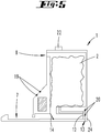
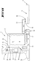
- FIG. 1 shows a schematic side view of a base station 1, which is formed, a vacuum cleaner 3, in particular a hand-held Stielstaubsauger, Ackusauger o.ä. take.
- the base station 1 has a first air inlet 7 and a first air outlet 8, which are adapted to be connected to an air outlet and an air inlet of the vacuum cleaner 3.
- At the base station 1 further contacts 19, 20 are arranged, which serve to make contact with the vacuum cleaner 3 to be connected to the base station 1, in particular they can also assume a support function for holding the vacuum cleaner 3 to the base station 1 or be equipped with sensors, to detect the docking of the vacuum cleaner 3.
- the base station 1 also has an interface 13, via which a second vacuum cleaner 4 can be connected to the base station 1.
- the interface 13 is covered in the figure with a cap 24.
- the base station 1 has a switch 22, with which the user can set certain cleaning operations.
- the switch 22 can assume different locking positions for the cleaning of the first vacuum cleaner 3 or the cleaning of the second vacuum cleaner 4.
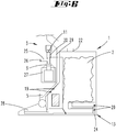
- FIG. 2 shows an adapter module 16, which can be connected to the interface 13 of the base station 1.
- the adapter module 16 has an adapter air outlet 17 for connection to the interface 13 and an adapter air inlet 18 for connection to a second vacuum cleaner 4.
- the adapter module 16 has a movable suction arm 23 which is pivotally mounted on a rotation axis and a second vacuum cleaner 4 to be connected can be lowered.
- the adapter module 16 can in particular to a specific Be adapted to vacuum cleaner type, which is to be connected to the base station 1. However, it is also possible that the adapter module 16 can connect several types of vacuum cleaner to the base station 1.
- FIG. 3 shows the base station 1 with a first vacuum cleaner connected thereto 3.
- the first vacuum cleaner 3 has at the usually resting on a floor to be cleaned side of a suction nozzle 28 which is connected here to the first air inlet 7 of the base station 1.
- the housing of the first vacuum cleaner 3 contacts the contacts 19 of the base station 1.
- the housing shape of the first vacuum cleaner 3 can be designed so that it correspondingly presses against the contacts 19 and distinguishes a particular type of vacuum cleaner from other vacuum cleaners.
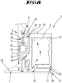
- FIG. 4 shows the base station 1 with the connected first vacuum cleaner 3, as already in FIG. 3 shown.
- the adapter module 16 is connected to the interface 13 of the base station 1.
- the covering cap 24 protecting the interface 13 has been removed from the base station 1.
- the adapter module 16 is connected with its adapter air outlet 17 to the interface 13.
- a second vacuum cleaner 4 designed here as a self-propelled vacuum robot.
- the pivotable suction arm 23 of the adapter module 16 can be pivoted into a position which corresponds to a docking position of the second vacuum cleaner 4 on the adapter module 16.
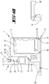
- FIG. 5 shows a cross section through the base station 1.
- the base station 1 has a base dust chamber 2, in which suction material 15 from the vacuum cleaners to be cleaned / emptied 3, 4 can be sucked.
- the base dust chamber 2 is connected to the first air inlet 7 and the first air outlet 8. Via this flow connection, air which is sucked from the first vacuum cleaner 3 through the first air inlet 7 into the base station 1 can flow through the base dust chamber 2 and subsequently leave the base station 1 again via the first air outlet 8 and, for example, a blower 11 of the first vacuum cleaner 3 are supplied.
- the interface 13, which provides a second air inlet 12, is also connected to the base dust chamber 2.
- the two flow paths from the first air inlet 7 to the first air outlet 8 and from the second air inlet 12 to the first air outlet 8 are separated by an inlet valve 14.
- the inlet valve 14 is designed here as a pivotable flap valve, but other designs are conceivable.
- the inlet valve 14 can be pivoted from a position closing the first air inlet 7 into a position closing the second air inlet 12, and vice versa.
- the base dust chamber 2 can be equipped in the usual way with a filter bag, which can be removed from the base station 1 and / or emptied when completely filled with suction material, for example. Dust and dirt.
- FIG. 6 shows a cross section through the in FIG. 5 illustrated base station 1 with a first vacuum cleaner connected thereto 3.
- the first vacuum cleaner 3 has a suction nozzle 28 which is connected to the first air inlet 7 of the base station 1. From the suction nozzle 28 to a blower 11 of the first vacuum cleaner 3, an air duct 9 runs inside the first vacuum cleaner 3.
- suction material 15 is sucked into the suction nozzle 28 from a floor to be cleaned by means of the blower 11, flows through the air duct 9 and thereby passes an air filter 27, which filters the sucked air, so that the suction material 15 contained therein adhere to the filter material of the air filter 27 and exclusively freed of suction material 15 air can flow further in the direction of the blower 11.
- a secondary air duct 25 is connected between the air filter 27 and the blower 11, which has a secondary air valve 26.
- secondary air channel 25 secondary air can flow into the air channel 9 of the first vacuum cleaner 3, which flows during a cleaning process of the first vacuum cleaner 3 in a flow direction, which the flow direction of the usual suction operation of the first vacuum cleaner 3 is opposite.
- the air duct 9 of the first vacuum cleaner 3 additionally has an inlet section 29 which connects the first air outlet 8 to the blower 11 of the first vacuum cleaner 3 in terms of flow.
- the inlet section 29 is associated with a valve 30 which can release or block a flow path from the base station 1 to the blower 11 of the first vacuum cleaner 3.
- the valve 30 is still in that position which is suitable for the usual suction operation of the first vacuum cleaner 3.
- the valve 30 closes the flow connection between the first air outlet 8 of the base station 1 and the air duct 9 of the first vacuum cleaner.
- FIG. 7 shows the base station 1 with the first vacuum cleaner 3 arranged thereon in a situation shortly before a cleaning process of the suction dust chamber 5 of the first vacuum cleaner 3.
- the switch 22 is pressed into a corresponding switching position.
- the valve 30 is pivoted to a position in which the air channel 9 between the fan 11 and the air filter 27 is fluidically separated.
- the inlet section 29 is released, which extends between the first air outlet 8 of the base station 1 and the blower 11 of the first vacuum cleaner 3.
- FIG. 8 shows a subsequent step in which the arranged on the secondary air passage 25 secondary air valve 26 is opened to admit secondary air for the cleaning process in the air duct 9 of the first vacuum cleaner 3.
- the inlet valve 14 arranged between the first air inlet 7 and the second air inlet 12 of the base station 1 is pivoted for the cleaning of the suction dust chamber 6 of the first vacuum cleaner 3 in a position in which the second air inlet 12 is closed, so that no air through the second air inlet 12 can flow into the base dust chamber 2. Accordingly, a flow path is between the first air inlet 7 and the first air outlet 8 via the base dust chamber 2 released.
- the cleaning process for the cleaning of the Saugerstaubraums 5 is now carried out so that the fan 11 via the first air outlet 8 successively generates a negative pressure in the base dust chamber 2, the suction nozzle 28, the Saugerstaubraum 5 and then the air filter 27 of the first vacuum cleaner 3.
- secondary air is sucked through the secondary air valve 26 into the secondary air channel 25, which flows through the air filter 27 in a direction opposite to a filter function of the air filter 27 flow direction.
- the outer wall of the air filter 27 is cleaned and the suction material 15 adhering thereto is sucked into the suction dust chamber 5.
- the total suction dust 15 located in the suction dust chamber 5 is then transferred through the suction nozzle 28 into the base dust chamber 2, where the suction material 15 is collected and can be disposed of during a subsequent cleaning process of the base dust chamber 2.
- the suction-laden air flowing through the base dust chamber 2 is thus cleaned and passes without suction material 15 via the first air outlet 8 to the blower 11 of the first vacuum cleaner 3.
- the first vacuum cleaner 3 is thus cleaned by means of its own blower 11, wherein in the suction dust chamber. 5 contained suction material 15 in the base dust chamber 2 of the base station 1 is transferred. It is not necessary that the base station 1 has its own fan, but the base station 1 may be formed as a passive station, which provides the corresponding flow paths and collects the suction material 15 within the base dust chamber 2.
- FIG. 9 shows the state of the base station 1 and the first vacuum cleaner 3 shortly after the successful cleaning of the first vacuum cleaner 3. This is the removed from the first vacuum cleaner 3 suction 15 in the base dust chamber 2 of the base station 1.
- the inlet valve 14 is pivoted back to its original position , which closes the first air inlet 7 of the base station 1, so that the suction material 15 contained in the base dust chamber 2 can not pass back into the first vacuum cleaner 3 through the suction nozzle 28.
- the adapter module 16 is connected to the interface 13 of the base station 1.
- the previously arranged on the interface 13 cap 24 is removed in order to connect an adapter air outlet 17 of the adapter module 16 to the second air inlet 12 of the base station 1 can.
- the arranged in the interface 13 contacts 20 may be formed so that they recognize the connection of the adapter module 16 to the base station 1 and, for example, a (additional) in the interface 13 arranged interface valve (not shown in the figure) share.
- the user can easily remove the cap 24 manually from the interface 13 and thus release the second air inlet 12 for the adapter module 16.
- the adapter module 16 is designed to provide a flow connection between the base station 1 and a second vacuum cleaner 4, for example a cleaning robot.
- the adapter module 16 has an air channel which connects the adapter air outlet 17 with the adapter air inlet 18.
- the position of the adapter air inlet 18 can be varied so that differently shaped and / or differently high second vacuum cleaner 4 can be connected.
- FIG. 11 shows the base station 1 with connected adapter module 16.
- the adapter air outlet 17 of the adapter module 16 is connected to the second air inlet 12 of the base station 1.
- the suction arm 23 is pivoted slightly downwardly to establish fluid communication with the air duct 10 of the second vacuum cleaner 4.
- the valve 30 is switched so that the blower 11 of the first vacuum cleaner 3 fluidly from the air filter 27 of the first vacuum cleaner 3 is separated.
- the inlet valve 14 is pivoted so that the first air inlet 7 of the base station 1 is closed and only the second air inlet 12 and the first air outlet 8 have a connection via the base dust chamber 2 to each other.
- the user of the base station 1 selects a corresponding cleaning program by means of the switch 22.
- the fan 11 is started, so that air from the second vacuum cleaner 4 flows into the adapter module 16 and thence through the base dust chamber 2 and finally to the blower 11 of the first vacuum cleaner 3.
- the air contained in the suction dust chamber 6 of the second vacuum cleaner 4 is guided via the adapter module 16 and the interface 13 into the base dust chamber 2 of the base station 1.
- a filter arranged in the base dust chamber 2 the air flowing in the direction of the blower 11 of the first vacuum cleaner 3 is cleaned of the suction material 15.
- the freed from the suction material 15 air can be discharged from the blower 11 into the environment.
- the invention provides a base station 1 to which one or more adapter modules 16 can be connected in a modular manner.
- the base station 1 has one or more interfaces 13, which are each designed for connection to adapter modules 16.
- the user of the base station 1 can choose which vacuum cleaner 3, 4 (suction dust chamber 5, 6) he would like to clean and which vacuum cleaner 3, 4 (blower 11) he wants to use for cleaning.
- the suction dust chamber 5 of the first vacuum cleaner 3 can be cleaned by means of the blower 11 of the first vacuum cleaner 3.
- the suction dust chamber 6 of the second vacuum cleaner 4 can also be cleaned by means of the blower 11 of the first vacuum cleaner 3.
- the second vacuum cleaner 4 which is connected to the base station 1 by means of the adapter module 16, is cleaned by means of its own blower.
- the second vacuum cleaner 4 is cleaned by means of its own blower.
- the second air outlet at the base station 1 through which air from the base dust chamber 2 in the Adapter module 16 can get to be sucked by the blower of the second vacuum cleaner 4.
Landscapes
- Engineering & Computer Science (AREA)
- Mechanical Engineering (AREA)
- Electric Vacuum Cleaner (AREA)
- Electric Suction Cleaners (AREA)
- Filters For Electric Vacuum Cleaners (AREA)
- Manipulator (AREA)
- Nozzles For Electric Vacuum Cleaners (AREA)
- Filtering Of Dispersed Particles In Gases (AREA)
Description
Die Erfindung betrifft eine Basisstation zum Reinigen und/oder Entleeren eines Saugerstaubraumes eines ersten Staubsaugers, welche Basisstation eine Basisstaubkammer, einen mit der Basisstaubkammer in Strömungsverbindung stehenden ersten Lufteintritt und einen mit der Basisstaubkammer in Strömungsverbindung stehenden ersten Luftaustritt aufweist, wobei der Lufteintritt und der Luftaustritt mit einem Luftkanal des ersten Staubsaugers verbindbar sind, sodass in dem Sauger-staubraum des ersten Staubsaugers enthaltenes Sauggut mittels eines Gebläses in die Basisstaubkammer förderbar ist. Das Gebläse kann ein Gebläse der Basisstation oder auch ein eigenes Gebläses des ersten Staubsaugers sein.The invention relates to a base station for cleaning and / or emptying a suction dust chamber of a first vacuum cleaner, which base station has a base dust chamber, a first air inlet in fluid communication with the base dust chamber and a first air outlet in fluid communication with the base dust chamber, wherein the air inlet and the air outlet with an air duct of the first vacuum cleaner can be connected, so that in the vacuum cleaner dust chamber of the first vacuum cleaner contained suction material is conveyed by means of a blower in the base dust chamber. The blower can be a blower of the base station or a separate blower of the first vacuum cleaner.
Basisstationen der vorgenannten Art sind im Stand der Technik hinreichend bekannt. Diese werden insbesondere in Kombination mit Staubsaugern verwendet, welche einen sogenannten Dauerfilter aufweisen, der bei vollständiger Füllung mit Sauggut nicht ausgewechselt wird, sondern mittels eines Spülluftstroms in einer der üblichen Saugrichtung entgegengesetzten Richtung von Staub befreit wird. Zu diesem Zweck kann der Saugerstaubraum des Staubsaugers an ein Gebläse der Basisstation oder an das eigene Gebläse des Staubsaugers angeschlossen werden.Base stations of the aforementioned type are well known in the art. These are used in particular in combination with vacuum cleaners, which have a so-called permanent filter, which is not replaced when completely filled with suction material, but is freed by means of a purge air flow in a direction opposite to the usual suction direction of dust. For this purpose, the suction dust chamber of the vacuum cleaner can be connected to a blower of the base station or to the own fan of the vacuum cleaner.
Die Druckschrift
Obwohl sich diese Art der Basisstation bewährt hat, ist diese nur zum Reinigen und/oder Entleeren eines einzigen Staubsaugers geeignet. Sofern ein Nutzer mehrere und/oder unterschiedliche Staubsauger benutzt, benötigt er mehrere Basisstationen.Although this type of base station has proven itself, it is only suitable for cleaning and / or emptying a single vacuum cleaner. If a user uses several and / or different vacuum cleaners, he needs several base stations.
Im Weiteren wird zum Stand der Technik auch auf die
Es ist Aufgabe der Erfindung, eine Basisstation zu schaffen, an welche mehrere Staubsauger gleichzeitig bzw. unterschiedliche Arten von Staubsaugern angeschlossen werden können. Die Basisstation soll darüber hinaus einen geringen Bauraum beanspruchen und möglichst geringe Kosten für den Kunden verursachen.It is an object of the invention to provide a base station to which a plurality of vacuum cleaners can be connected simultaneously or different types of vacuum cleaners. The base station should also take up a small space and cause the lowest possible cost for the customer.
Zur Lösung der vorgenannten Aufgabe schlägt die Erfindung vor, dass die Basisstation mindestens eine Schnittstelle zur lösbaren Verbindung mit einem Adaptermodul aufweist, welche Schnittstelle einen absperrbaren, mit der Basisstaubkammer in Strömungsverbindung stehenden zweiten Lufteintritt aufweist, über welchen bei Verbindung des Adaptermoduls mit einem zweiten Staubsauger in einem Sauger-staubraum des zweiten Staubsaugers enthaltenes Sauggut in die Basisstaubkammer förderbar ist.To achieve the above object, the invention proposes that the base station has at least one interface for detachable connection with an adapter module, which interface has a closable, with the base dust chamber in flow connection second air inlet, via which when connecting the adapter module with a second vacuum cleaner in a suction dust chamber of the second vacuum cleaner contained suction material is conveyed into the base dust chamber.
Durch die Erfindung wird eine modular erweiterbare Basisstation geschaffen, welche abhängig von der Art des oder der zu reinigenden Staubsauger um ein oder mehrere Adaptermodule ergänzt werden kann. Die Basisstation weist dafür eine oder mehrere Schnittstellen auf, an welche je nach Bedarf Adaptermodule angeschlossen werden können. Es ist somit nicht erforderlich, dass ein Nutzer zur Reinigung/ zum Entleeren zweier verschiedener Staubsauger, bspw. eines handgeführten Akkustaubsaugers und eines Saugroboters, zwei verschiedene Basisstationen anschafft. Vielmehr kann der Nutzer die Basisstation, welche bereits zum Reinigen/Entleeren eines bestimmten Staubsaugertypen ausgebildet ist, um Adaptermodule für weitere Staubsaugertypen ergänzen. Dadurch kann die Basisstation ganz nach den individuellen Bedürfnissen des Nutzers gestaltet werden. Zudem kann die Basisstation dadurch geringstmöglich klein ausgebildet werden. Darüber hinaus muss der Nutzer auch keine serienmäßig an der Basisstation angeordneten Schnittstellen für solche Staubsauger mitbezahlen, welche er ggf. gar nicht benötigt, da er den jeweiligen Staubsaugertyp nicht verwendet. Im Ergebnis ist es möglich, dass der Nutzer eine Basisstation und ein Adaptermodul oder mehrere Adaptermodule anschafft, welche zu den von ihm eingesetzten Staubsaugertypen korrespondieren.The invention provides a modular expandable base station is created, which can be supplemented by one or more adapter modules depending on the nature of the or to be cleaned vacuum cleaner. The base station has for this purpose one or more interfaces to which adapter modules can be connected as needed. It is thus not necessary for a user to purchase two different base stations for cleaning / emptying two different vacuum cleaners, for example a hand-held cordless vacuum cleaner and a vacuum robot. Instead, the user can supplement the base station, which is already designed for cleaning / emptying a specific type of vacuum cleaner, with adapter modules for further vacuum cleaner types. This allows the base station to be designed according to the individual needs of the user. In addition, the base station can thereby be formed as small as possible. In addition, the user does not pay any standard arranged at the base station interfaces for such vacuum cleaners, which he may not need, because he does not use the respective type of vacuum cleaner. As a result, it is possible for the user to purchase a base station and an adapter module or a plurality of adapter modules which correspond to the vacuum cleaner types used by him.
Es wird vorgeschlagen, dass das in dem Saugerstaubraum des zweiten Staubsaugers enthaltene Sauggut mittels eines Gebläses der Basisstation, mittels eines Gebläses des zweiten Staubsaugers oder mittels des Gebläses des ersten Staubsaugers in die Basis-staubkammer förderbar ist. Der zweite Lufteintritt der Basisstation kann somit via der Basisstaubkammer vorteilhaft auch mit einem eigenen Gebläse des abzusaugenden zweiten Staubsaugers oder mit einem Gebläse eines weiteren Staubsaugers (bspw. des ersten Staubsaugers) abgereinigt werden. Je nachdem, welche Staubsaugertypen an die Basisstation angeschlossen sind, kann der Nutzer vorteilhaft mittels eines Wahlschalters wählen, welcher Saugerstaubraum geleert werden soll und welches Staubsaugergebläse dazu verwendet werden soll. Vorteilhaft kann hierzu das jeweils leistungsstärkere Gebläse gewählt werden. Innerhalb der Basisstation werden die Strömungswege dann so miteinander verbunden, dass die Luft aus dem zu reinigenden Staubsauger entweder zu dem Gebläse dieses Staubsaugers oder zu dem Gebläse eines anderen Staubsaugers strömt. Sofern der Saugerstaubraum des zweiten Staubsaugers mittels des eigenen Gebläses des zweiten Staubsaugers gereinigt werden soll, korrespondiert der zweite Lufteintritt der Basisstation, an welchen das Adaptermodul und somit auch der zweite Staubsauger angeschlossen ist, strömungstechnisch mit einem zweiten Luftaustritt der Basisstation, welcher ebenfalls in Strömungsverbindung mit dem Adaptermodul bzw. dem zweiten Staubsauger steht.It is proposed that the suction material contained in the suction dust chamber of the second vacuum cleaner can be conveyed into the base dust chamber by means of a blower of the base station, by means of a blower of the second vacuum cleaner or by means of the blower of the first vacuum cleaner. The second air inlet of the base station can thus be cleaned via the base dust chamber advantageously also with its own blower of the second vacuum cleaner or with a blower of another vacuum cleaner (eg. The first vacuum cleaner). Depending on which types of vacuum cleaner are connected to the base station, the user can advantageously choose by means of a selector switch, which Saugerstaubraum should be emptied and which vacuum cleaner fan to be used. Advantageously, the more powerful fan can be selected for this purpose. Within the base station, the flow paths are then interconnected so that the air from the vacuum cleaner to be cleaned either flows to the blower of this vacuum cleaner or to the blower of another vacuum cleaner. If the suction dust space of the second vacuum cleaner is to be cleaned by means of its own blower of the second vacuum cleaner, the second air inlet of the base station to which the adapter module and thus the second vacuum cleaner is connected, fluidically with a second air outlet of the base station, which also in fluid communication with the adapter module or the second vacuum cleaner stands.
Vorteilhaft ist dem ersten Lufteintritt und/oder dem zweiten Lufteintritt der Basisstation ein Eintrittsventil zugeordnet, welches in Abhängigkeit von einer gewünschten Förderung von Sauggut aus dem Saugerstaubraum des ersten Staubsaugers oder aus dem Saugerstaubraum des zweiten Staubsaugers umschaltbar ist. Es können somit alternative Strömungswege innerhalb der Basisstation ausgebildet werden, je nachdem ob ein erster oder ein zweiter Staubsauger, welcher an die Basisstation angeschlossen ist, gereinigt werden soll.Advantageously, an inlet valve is assigned to the first air inlet and / or the second air inlet of the base station, which can be switched in dependence on a desired delivery of suction material from the suction dust chamber of the first vacuum cleaner or from the suction dust chamber of the second vacuum cleaner. Thus, alternative flow paths can be formed within the base station, depending on whether a first or a second vacuum cleaner, which is connected to the base station, to be cleaned.
Gemäß einer ersten Ausführungsform kann bspw. nur ein erster Staubsauger an die Basisstation angeschlossen sein, wobei grundsätzlich die Verbindung des zweiten Lufteintritts mit einem Adaptermodul überflüssig ist. Dabei wird die Basisstation in der einfachsten Ausführungsform verwendet. Die Reinigung des Saugerstaubraumes dieses Staubsaugers erfolgt so, dass der erste Lufteintritt und der erste Luftaustritt der Basisstation mit dem Luftkanal des ersten Staubsaugers verbunden werden, sodass in dem Saugerstaubraum enthaltenes Sauggut mittels des Gebläses des zu reinigenden ersten Staubsaugers in die Basisstaubkammer gefördert wird. Um eine Auswahl für einen Reinigungsvorgang zu schaffen, kann die Basisstation bspw. einen Schalter aufweisen, welchen der Nutzer der Basisstation manuell betätigen kann. Über den Schalter können mehrere Funktionen gewählt werden, wobei nur diejenigen Funktionen wählbar sein können, welche mittels der an die Basisstation angeschlossenen Staubsauger verfügbar sind. Zusätzlich kann der Schalter auch in mehreren Stufen betätigbar sein, bspw. für eine Aktivierung eines Gebläses durch ein lediglich leichtes Drücken des Schalters, und für das Schalten eines bestimmten Strömungsweges durch ein vollständiges Durchdrücken des Schalters. Wenn bspw. sowohl ein erster als auch ein zweiter Staubsauger an die Basisstation angeschlossen sind, kann der Nutzer eine Auswahl darüber treffen, ob er den zweiten Staubsauger mittels des Gebläses des zweiten Staubsaugers oder mittels des Gebläses des ersten Staubsaugers reinigen möchte. Die Auswahl, welcher Staubsauger gereinigt werden soll und welcher Staubsauger das Gebläse für die Reinigung zur Verfügung stellt, kann ebenfalls mittels Schalter gewählt werden.According to a first embodiment, for example, only a first vacuum cleaner may be connected to the base station, wherein in principle the connection of the second air inlet with an adapter module is superfluous. In this case, the base station is used in the simplest embodiment. The cleaning of the suction dust space of this vacuum cleaner is such that the first air inlet and the first air outlet of the base station are connected to the air duct of the first vacuum cleaner, so contained in the Saugerstaubraum Suction is conveyed by means of the blower of the first vacuum cleaner to be cleaned in the base dust chamber. In order to provide a selection for a cleaning process, the base station may, for example, have a switch which the user of the base station can manually operate. Several functions can be selected via the switch, whereby only those functions can be selected, which are available by means of the vacuum cleaner connected to the base station. In addition, the switch can also be actuated in several stages, for example for an activation of a blower by merely pressing the switch lightly, and for switching a specific flow path by completely pushing the switch. For example, if both a first and a second vacuum cleaner are connected to the base station, the user may make a choice as to whether to clean the second vacuum cleaner by means of the blower of the second vacuum cleaner or by means of the blower of the first vacuum cleaner. The choice of which vacuum cleaner to clean and which vacuum cleaner the blower provides for cleaning can also be selected by means of a switch.
Gemäß einer zweiten Ausführungsform kann die Schaltung der Luftwege elektromechanisch anstatt manuell durch den Nutzer erfolgen. Bei dieser Ausgestaltung erkennt die Basisstation selbstständig, welche Staubsauger an den ersten Lufteintritt, den zweiten Lufteintritt und ggf. weitere Lufteintritte angeschlossen sind und initiiert bei bestimmten Kombinationen von angeschlossenen Staubsaugern eine bestimmte Reinigungsvariante. Sofern bspw. nur ein erster Staubsauger an die Basisstation angeschlossen ist, werden die Strömungswege innerhalb der Basisstation so geschaltet, dass der Saugerstaubraum des ersten Staubsaugers mittels des Gebläses des ersten Staubsaugers gereinigt wird. Sofern stattdessen bspw. an den ersten Lufteintritt der Basisstation ein erster Staubsauger angeschlossen ist und an den zweiten Lufteintritt ein Adaptermodul mit einem zweiten Staubsauger, kann die Basisstation so ausgebildet sein, dass als Voreinstellung grundsätzlich eine Absaugung des zweiten Staubsaugers mittels des Gebläses des ersten Staubsaugers durchgeführt wird. Alternativ wäre es jedoch auch möglich, dass der Saugerstaubraum des zweiten Staubsaugers mittels des Gebläses des zweiten Staubsaugers abgereinigt wird. Zusätzlich können bspw. auch bestimmte Reinigungsabfolgen festgelegt sein, wonach mehrere an die Basisstation angeschlossene Staubsauger in einer festgelegten Reihenfolge nacheinander gereinigt werden. Bspw. kann vorgesehen sein, dass stets zuerst eine Reinigung des Saugerstaubraums des ersten Staubsaugers erfolgt und die Reinigungsvorgänge für die weiteren Staubsauger nachrangig sind. Vorteilhaft kann die Basisstation mittels im Bereich der Lufteintritte und ggf. auch Luftaustritte angeordneter Kontakte erkennen, ob Staubsauger und/oder Adaptermodule an die Basisstation angeschlossen sind. Ggf. kann über die Art der Kontakte auch eine Erkennung bestimmter Staubsaugertypen erfolgen.According to a second embodiment, the circuit of the airways can be done electromechanically rather than manually by the user. In this embodiment, the base station recognizes independently which vacuum cleaner is connected to the first air inlet, the second air inlet and possibly further air inlets and initiated in certain combinations of connected vacuum cleaners a certain cleaning variant. If, for example, only a first vacuum cleaner is connected to the base station, the flow paths within the base station are switched so that the suction dust chamber of the first vacuum cleaner is cleaned by means of the blower of the first vacuum cleaner. If instead, for example, at the first air inlet of the base station, a first vacuum cleaner is connected and to the second air inlet Adapter module with a second vacuum cleaner, the base station can be designed so that basically a suction of the second vacuum cleaner by means of the blower of the first vacuum cleaner is performed as a default. Alternatively, however, it would also be possible for the suction dust chamber of the second vacuum cleaner to be cleaned by means of the blower of the second vacuum cleaner. In addition, for example, certain cleaning sequences can also be defined, according to which a plurality of vacuum cleaners connected to the base station are cleaned one after the other in a fixed sequence. For example. It can be provided that always first a cleaning of the suction dust chamber of the first vacuum cleaner takes place and the cleaning operations for the other vacuum cleaners are subordinate. Advantageously, the base station can recognize by means of contacts arranged in the area of the air inlets and possibly also air outlets, whether vacuum cleaners and / or adapter modules are connected to the base station. Possibly. can be done on the nature of the contacts and a recognition of certain types of vacuum cleaner.
Vorgeschlagen wird bspw. eine Ausbildung, bei welcher das Eintrittsventil der Basisstation für eine Förderung von Sauggut aus dem Saugerstaubraum des zweiten Staubsaugers so umschaltbar ist, dass dieses den ersten Lufteintritt versperrt, und dass das Eintrittsventil für eine Förderung von Sauggut aus dem Saugerstaubraum des ersten Staubsaugers so umschaltbar ist, dass dieses den zweiten Lufteintritt versperrt. Das Eintrittsventil ist somit zwischen zwei verschiedenen Stellungen umschaltbar, von welchen eine erste Stellung einen Strömungsweg zu dem Adapter-modul herstellt, während eine zweite Stellung ausgebildet ist, Sauggut aus dem Saugerstaubraum des ersten Staubsaugers zu fördern. Je nach dem geschalteten Strömungsweg des Saugguts von dem ersten Lufteintritt bzw. dem zweiten Lufteintritt muss der jeweils andere Lufteintritt, d.h. entweder der zweite Lufteintritt oder der erste Lufteintritt, verschlossen werden, was vorteilhaft zeitgleich durch das Eintrittsventil erfolgt. Das Eintrittsventil erfüllt somit gleichzeitig die Funktion des Öffnens eines ersten Strömungsweges und die Funktion des Schließens eines zweiten Strömungsweges.It is proposed, for example, an embodiment in which the inlet valve of the base station for conveying suction material from the Saugerstaubraum the second vacuum cleaner is switchable so that this obstructs the first air inlet, and that the inlet valve for the promotion of suction material from the Saugstaubraum the first vacuum cleaner is switchable so that this obstructs the second air inlet. The inlet valve is thus switchable between two different positions, of which a first position produces a flow path to the adapter module, while a second position is formed to promote suction material from the suction dust chamber of the first vacuum cleaner. Depending on the switched flow path of the suction material from the first air inlet or the second air inlet of the other air inlet, ie either the second air inlet or the first air inlet, closed be, which is advantageously carried out at the same time by the inlet valve. The inlet valve thus simultaneously fulfills the function of opening a first flow path and the function of closing a second flow path.
Es wird vorgeschlagen, dass das Eintrittsventil einer Ventilsteuerung zugeordnet ist, welche eingerichtet ist, das Eintrittsventil bei Verbindung eines Adaptermoduls mit dem zweiten Lufteintritt automatisch so umzuschalten, dass der erste Lufteintritt versperrt ist. Gemäß dieser Ausgestaltung ist vorgeschlagen, dass die Ventilsteuerung als Grundeinstellung der Strömungswege bei einem mit der Basisstation verbundenen Adaptermodul automatisch den ersten Lufteintritt versperrt und den zweiten Lufteintritt freischaltet. Insofern wird ein ggf. noch existierender Strömungsweg, welcher für eine Reinigung des ersten Staubsaugers geeignet ist, getrennt und ein Strömungsweg, welcher für die Reinigung des zweiten Staubsaugers, der an das Adaptermodul angeschlossen ist, geeignet ist, freigeschaltet. Eine solche Voreinstellung bietet sich bspw. an, falls der erste Staubsauger ein netzbetriebener Bodenstaubsauger ist und der zweite Staubsauger ein Reinigungsroboter, dessen Saugerstaubraum grundsätzlich ein geringeres Staubfassungsvermögen hat als der Saugerstaubraum des netzbetriebenen Staubsaugers.It is proposed that the inlet valve is assigned to a valve control which is set up to automatically switch over the inlet valve upon connection of an adapter module to the second air inlet in such a way that the first air inlet is blocked. According to this embodiment, it is proposed that the valve control, as a basic setting of the flow paths in an adapter module connected to the base station, automatically blocks the first air inlet and releases the second air inlet. In this respect, a possibly still existing flow path, which is suitable for cleaning the first vacuum cleaner, separated and a flow path, which is suitable for the cleaning of the second vacuum cleaner, which is connected to the adapter module, unlocked. Such a presetting is, for example, on, if the first vacuum cleaner is a mains operated vacuum cleaner and the second vacuum cleaner is a cleaning robot, the vacuum cleaner space basically has a lower dust capacity than the vacuum cleaner space of the mains-powered vacuum cleaner.
Es kann vorgesehen sein, dass die Schnittstelle eine den zweiten Lufteintritt reversibel absperrende Abdeckkappe aufweist und/oder ein Schnittstellenventil, welches eingerichtet sein kann, den zweiten Lufteintritt bei dessen Verbindung mit einem Adaptermodul zu öffnen. Im zuerst vorgeschlagenen Fall, dass die Schnittstelle eine Abdeckkappe aufweist, kann die Abdeckkappe bspw. manuell betätigbar und/oder entfernbar an dem zweiten Lufteintritt der Basisstation angeordnet sein. Die Funktion der Abdeckkappe besteht dabei darin, dass diese bspw. bei einer Reinigung eines an dem ersten Lufteintritt angeordneten Staubsaugers einen Eintritt von Nebenluft durch den zweiten Lufteintritt in die Basisstation verhindert. Die Abdeckkappe kann grundsätzlich manuell oder elektromechanisch betätigbar sein und unterschiedliche Ausführungsformen aufweisen, bspw. als Klappe, Stopfen o.ä. ausgebildet sein. In dem zweitgenannten Fall, dass die Schnittstelle ein den zweiten Lufteintritt absperrendes Schnittstellenventil aufweist, ist insbesondere eine elektromechanische Betätigung bevorzugt, bei welcher das Ventil unmittelbar öffnet, wenn ein Adaptermodul an den zweiten Lufteintritt angeschlossen wird. Der Nutzer der Basisstation muss den zweiten Lufteintritt somit nicht mehr manuell öffnen, sondern lediglich das Adaptermodul mit der Schnittstelle verbinden, wodurch eine automatische Öffnung erfolgt. Die Schnittstelle ist analog ohne angebrachtes Adaptermodul - selbsttätig, hervorgerufen durch Abnahme - verschlossen.It may be provided that the interface has a cap which reversibly closes off the second air inlet and / or an interface valve which can be set up to open the second air inlet when it is connected to an adapter module. In the first case proposed that the interface has a cap, the cap can, for example, be arranged manually operable and / or removable at the second air inlet of the base station. The function of the cap is to that, for example, this prevents the ingress of secondary air through the second air inlet into the base station when cleaning a vacuum cleaner arranged at the first air inlet. The cap can in principle be manually or electromechanically actuated and have different embodiments, for example. As a flap, plug or the like. be educated. In the second-mentioned case that the interface has an interface valve shutting off the second air inlet, in particular an electromechanical actuation is preferred in which the valve opens directly when an adapter module is connected to the second air inlet. The user of the base station must therefore no longer manually open the second air inlet, but merely connect the adapter module to the interface, whereby an automatic opening is made. The interface is analog without attached adapter module - automatically, caused by acceptance - closed.
In diesem Zusammenhang wird des Weiteren vorgeschlagen, dass das Schnittstellenventil durch mechanische Einwirkung eines Teilbereiches des Adaptermoduls, insbesondere eines Adapterluftaustritts, öffenbar ist. Eine mit dem Schnittstellenventil verbundene Schnittstellensteuerung kann dabei einen mechanischen Kontakt zwischen der Schnittstelle und einem Adaptermodul erkennen, bspw. dadurch, dass ein Adapterluftaustritt des Adaptermoduls die Schnittstelle kontaktiert, bspw. indem ein Teilbereich eines Adapterluftkanals in einen Teilbereich des zweiten Lufteintritts hineinragt, ähnlich einer Steckverbindung. An der Schnittstelle angeordnete mechanische Kontakte können dabei einen Kontakt eines Adaptermoduls an der Basisstation im Bereich des zweiten Lufteintritts erkennen, ein entsprechendes Signal an die Ventilsteuerung senden, welche schließlich den Öffnungsbefehl ausgibt.In this context, it is further proposed that the interface valve can be opened by mechanical action of a partial region of the adapter module, in particular of an adapter air outlet. In this case, an interface controller connected to the interface valve can detect a mechanical contact between the interface and an adapter module, for example by an adapter air outlet of the adapter module contacting the interface, for example by a partial region of an adapter air duct projecting into a partial region of the second air inlet, similar to a plug connection , At the interface arranged mechanical contacts can detect a contact of an adapter module to the base station in the region of the second air inlet, send a corresponding signal to the valve control, which finally outputs the opening command.
Neben der vorangehend dargestellten erfindungsgemäßen Basisstation wird ebenso ein Basisstationssystem vorgeschlagen, welches eine Basisstation nach einer der vorgenannten Ausführungsformen und ein mit der Schnittstelle der Basisstation verbindbares Adaptermodul aufweist, wobei das Adaptermodul einen zu der Schnittstelle korrespondierenden Adapterluftaustritt sowie einen mit einem Luftkanal eines zweiten Staubsaugers verbindbaren Adapterlufteintritt aufweist. Das Adaptermodul funktioniert dabei als Adapter zwischen der Basisstation und einem zweiten Staubsauger, wobei das Adaptermodul einerseits einen zu der Schnittstelle korrespondierenden Adapterluftaustritt und andererseits einen mit einer Schnittstelle eines zweiten Staubsaugers korrespondierenden Adapterlufteintritt aufweist. Insgesamt wird somit ein Luftkanal geschaffen, welcher zum einen einen Saugerstaubraum des zweiten Staubsaugers via des durch das Adaptermodul bereitgestellten Luftkanals mit einem Strömungsweg der Basisstation zu einem Gebläse verbindet. Das Gebläse kann bspw. das Gebläse eines ersten Staubsaugers, das Gebläse des zweiten Staubsaugers oder auch das Gebläse der Basisstation sein. Bei jeder der genannten Alternativen führt der Strömungsweg über die Basisstaubkammer der Basisstation, sodass das in dem Saugerstaubraum des zu reinigenden Staubsaugers enthaltene Sauggut in der Basisstation gesammelt werden kann.In addition to the base station according to the invention shown above, a base station system is also proposed, which has a base station according to one of the aforementioned embodiments and connectable to the interface of the base station adapter module, the adapter module corresponding to the interface adapter air outlet and connectable to an air duct of a second vacuum cleaner adapter air inlet having. The adapter module functions as an adapter between the base station and a second vacuum cleaner, wherein the adapter module on the one hand has an adapter air outlet corresponding to the interface and on the other hand has an adapter air inlet corresponding to an interface of a second vacuum cleaner. Overall, thus, an air channel is created, which connects to a suction dust chamber of the second vacuum cleaner via the air duct provided by the adapter module with a flow path of the base station to a fan on the one hand. For example, the blower may be the blower of a first vacuum cleaner, the blower of the second vacuum cleaner or the blower of the base station. In each of the alternatives mentioned, the flow path leads via the base dust chamber of the base station, so that the suction material contained in the suction dust chamber of the vacuum cleaner to be cleaned can be collected in the base station.
Des Weiteren wird mit der Erfindung ein Adaptermodul zur lösbaren Verbindung mit einem Staubsauger und einer Basisstation, insbesondere einer erfindungsgemäßen Basisstation, vorgeschlagen, um Sauggut aus einem Saugerstaubraum des Staubsaugers in eine Basisstaubkammer der Basisstation zu fördern, wobei das Adaptermodul einen durch Formschluss, Kraftschluss und/oder Saugkraft eines Gebläses mit der Basisstation verbindbaren Adapterluftaustritt und einen durch Formschluss, Kraftschluss und/oder Saugkraft eines Gebläses mit dem Staubsauger verbindbaren Adapterlufteintritt aufweist. Beispielsweise kann das Adaptermodul im Bereich des Adapterluftaustritts und/oder Adapterlufteintritts entsprechende Verbindungsmittel aufweisen, beispielsweise Rastmittel, Klemmmittel oder ähnliches. Darüber hinaus ist bspw. auch eine Steckverbindung möglich, welche ggf. durch die Saugkraft des Gebläses verstärkt wird. Das Adaptermodul weist einen beweglichen Saugarm auf, welcher schwenkbeweglich an einer Rotationsachse angeordnet ist und mit dem eine Position des Adapterlufteintritts (18) variiert werden kann, so dass unterschiedlich geformte und/oder unterschiedlich hohe Staubsauger angeschlossen werden können.Furthermore, the invention proposes an adapter module for releasable connection to a vacuum cleaner and a base station, in particular a base station according to the invention, in order to convey suction material from a suction dust chamber of the vacuum cleaner into a base dust chamber of the base station, wherein the adapter module has a positive connection, adhesion and / or or suction power of a blower with the base station connectable adapter air outlet and a connectable by positive engagement, adhesion and / or suction of a blower with the vacuum cleaner adapter air inlet. For example, in the region of the adapter air outlet and / or adapter air inlet, the adapter module can have corresponding connection means, for example latching means, clamping means or the like. In addition, for example, a connector is possible, which is possibly reinforced by the suction force of the blower. The adapter module has a movable suction arm, which is arranged pivotably on a rotation axis and with which a position of the adapter air inlet (18) can be varied, so that differently shaped and / or different vacuum cleaner can be connected.
Des Weiteren wird mit der Erfindung ebenfalls ein Verfahren zum Reinigen und/oder Entleeren eines Saugerstaubraumes eines ersten Staubsaugers mittels einer Basisstation vorgeschlagen, insbesondere mittels einer erfindungsgemäßen Basisstation, wobei ein Luftkanal des ersten Staubsaugers mit einem mit einer Basisstaubkammer der Basisstation in Strömungsverbindung stehenden ersten Lufteintritt und ersten Luftaustritt der Basisstation verbunden wird, und wobei in dem Sauger-staubraum des ersten Staubsaugers enthaltenes Sauggut mittels eines Gebläses, insbesondere eines Gebläses des ersten Staubsaugers, in die Basisstaubkammer gefördert wird, und wobei mindestens eine einen zweiten Lufteintritt aufweisendeFurthermore, the invention also proposes a method for cleaning and / or emptying a suction dust chamber of a first vacuum cleaner by means of a base station, in particular by means of a base station according to the invention, wherein an air duct of the first vacuum cleaner with a first air inlet in fluid communication with a base dust chamber of the base station and the first air outlet of the base station is connected, and wherein in the vacuum cleaner room of the first vacuum cleaner suction material is conveyed by means of a blower, in particular a blower of the first vacuum cleaner in the base dust chamber, and wherein at least one second air inlet having
Schnittstelle der Basisstation mit einem Adaptermodul verbunden wird, wobei das Adaptermodul anschließend mit einem zweiten Staubsauger verbunden wird, und wobei in einem Saugerstaubraum des zweiten Staubsaugers enthaltenes Sauggut in die Basisstaubkammer gefördert wird.Interface of the base station is connected to an adapter module, wherein the adapter module is then connected to a second vacuum cleaner, and wherein suction material contained in a suction dust chamber of the second vacuum cleaner is conveyed into the base dust chamber.
Im Übrigen gelten die in Bezug auf die Basisstation bzw. das Basisstationssystem beschriebenen Vorteile und Ausführungsvarianten selbstverständlich auch für das erfindungsgemäße Verfahren.Incidentally, the advantages and variants described in relation to the base station or the base station system naturally also apply to the method according to the invention.
Insbesondere wird vorgeschlagen, dass das in dem Saugerstaubraum des zweiten Staubsaugers enthaltene Sauggut mittels eines Gebläses des zweiten Staubsaugers oder mittels eines Gebläses des ersten Staubsaugers in die Basisstaubkammer gefördert wird. Insbesondere kann sich bei dem Reinigungsvorgang und/oder Entleerungsvorgang des Saugerstaubraums auch eine Wahlmöglichkeit für den Nutzer der Basisstation ergeben, wobei er entscheiden kann, ob der Saugerstaubraum des zweiten Staubsaugers mittels des Gebläses des ersten oder zweiten Staubsaugers gereinigt/ entleert wird. Neben einer Wahlmöglichkeit durch den Nutzer kann das Verfahren alternativ eine automatische Wahl des verwendeten Gebläses vorsehen, insbesondere in Abhängigkeit einer aktuellen Kombination der an der Basisstation angeschlossenen Staubsaugertypen.In particular, it is proposed that the suction material contained in the suction dust chamber of the second vacuum cleaner is conveyed into the base dust chamber by means of a blower of the second vacuum cleaner or by means of a blower of the first vacuum cleaner. In particular, during the cleaning process and / or emptying process of the suction dust space can also be a choice for the user of the base station, where he can decide whether the Saugerstaubraum the second vacuum cleaner is cleaned / emptied by the blower of the first or second vacuum cleaner. In addition to a choice by the user, the method may alternatively provide an automatic choice of the blower used, in particular depending on a current combination of connected to the base station vacuum cleaner types.
Des Weiteren kann vorgesehen sein, dass ein dem ersten Lufteintritt und/oder dem zweiten Lufteintritt zugeordnetes Eintrittsventil in Abhängigkeit von einer gewünschten Förderung von Sauggut aus dem Saugerstaubraum des ersten Staubsaugers oder aus dem Saugerstaubraum des zweiten Staubsaugers umgeschaltet wird. Insbesondere kann das Eintrittsventil für eine Förderung von Sauggut aus dem Saugerstaubraum des zweiten Staubsaugers so umgeschaltet werden, dass dieses den ersten Lufteintritt versperrt, und kann das Eintrittsventil für eine Förderung von Sauggut aus dem Saugerstaubraum des ersten Staubsaugers so umgeschaltet werden, dass dieses den zweiten Lufteintritt versperrt. In jedem der genannten Fälle wird mittels der aktuellen Stellung des Eintrittsventils nicht nur die gewünschte Strömungsverbindung zu dem jeweiligen Lufteintritt hergestellt, sondern vielmehr auch ein Eindringen von Nebenluft durch den jeweils anderen (nicht verwendeten) Lufteintritt verhindert.Furthermore, it can be provided that an inlet valve assigned to the first air inlet and / or the second air inlet is switched over from the suction dust chamber of the first vacuum cleaner or from the suction dust chamber of the second vacuum cleaner depending on a desired delivery of suction material. In particular, the inlet valve for the promotion of suction material from the Saugstaubraum the second vacuum cleaner can be switched so that this obstructs the first air inlet, and the inlet valve for the promotion of suction material from the Saugerstaubraum the first vacuum cleaner can be switched so that this the second air inlet blocked. In each of the cases mentioned, the current position of the inlet valve not only the desired Flow connection made to the respective air inlet, but also prevents ingress of secondary air through the other (unused) air inlet.
Im Folgenden wird die Erfindung anhand eines Ausführungsbeispiels näher erläutert. Es zeigen:
- Figur 1:
- Eine Basisstation in einer schematischen Seitenansicht,
- Figur 2:
- ein Adaptermodul in einer schematischen Seitenansicht,
- Figur 3:
- die Basisstation mit einem ersten Staubsauger,
- Figur 4:
- die Basisstation mit dem ersten Staubsauger sowie dem Adaptermodul mit einem zweiten Staubsauger,
- Figur 5:
- die Basisstation in einer geschnittenen Ansicht,
- Figur 6:
- die Basisstation mit dem daran angeordneten ersten Staubsauger in einer geschnittenen Ansicht,
- Figur 7:
- die Basisstation mit dem ersten Staubsauger gemäß
Figur 6 mit einer ersten Stellung eines Eintrittsventils, - Figur 8:
- die Basisstation mit dem ersten Staubsauger mit einer zweiten Stellung des Eintrittsventils,
- Figur 9:
- die Basisstation mit dem ersten Staubsauger nach erfolgter Reinigung,
- Figur 10:
- die Basisstation mit dem ersten Staubsauger und dem Adaptermodul in einer geschnittenen Ansicht,
- Figur 11:
- die Basisstation mit dem ersten Staubsauger, dem Adaptermodul und dem zweiten Staubsauger in geschnittener Ansicht.
- FIG. 1:
- A base station in a schematic side view,
- FIG. 2:
- an adapter module in a schematic side view,
- FIG. 3:
- the base station with a first vacuum cleaner,
- FIG. 4:
- the base station with the first vacuum cleaner and the adapter module with a second vacuum cleaner,
- FIG. 5:
- the base station in a cutaway view,
- FIG. 6:
- the base station with the first vacuum cleaner arranged thereon in a sectional view,
- FIG. 7:
- the base station with the first vacuum cleaner according to
FIG. 6 with a first position of an inlet valve, - FIG. 8:
- the base station with the first vacuum cleaner with a second position of the inlet valve,
- FIG. 9:
- the base station with the first vacuum cleaner after cleaning,
- FIG. 10:
- the base station with the first vacuum cleaner and the adapter module in a sectional view,
- FIG. 11:
- the base station with the first vacuum cleaner, the adapter module and the second vacuum cleaner in a sectional view.
Die Basisstation 1 verfügt über einen Schalter 22, mit welchem der Nutzer bestimmte Reinigungsvorgänge einstellen kann. Bspw. kann der Schalter 22 unterschiedliche Raststellungen für die Reinigung des ersten Staubsaugers 3 oder die Reinigung des zweiten Staubsaugers 4 einnehmen.The
Die Basisstaubkammer 2 kann in üblicher Weise mit einem Filterbeutel ausgestattet sein, welcher bei vollständiger Füllung mit Sauggut, bspw. Staub und Schmutz, aus der Basisstation 1 entfernt und/oder geleert werden kann.The
An den Luftkanal 9 ist zwischen dem Luftfilter 27 und dem Gebläse 11 ein Nebenluftkanal 25 angeschlossen, welcher ein Nebenluftventil 26 aufweist. Durch den Nebenluftkanal 25 kann Nebenluft in den Luftkanal 9 des ersten Staubsaugers 3 einströmen, die während eines Reinigungsvorgangs des ersten Staubsaugers 3 in eine Strömungsrichtung strömt, welche der Strömungsrichtung des üblichen Saugbetriebs des ersten Staubsaugers 3 entgegengerichtet ist. Um den ersten Staubsauger 3 an den ersten Luftaustritt 8 der Basisstation 1 anschließen zu können, weist der Luftkanal 9 des ersten Staubsaugers 3 zusätzlich einen Eintrittsabschnitt 29 auf, welcher den ersten Luftaustritt 8 strömungstechnisch mit dem Gebläse 11 des ersten Staubsaugers 3 verbindet. Dem Eintrittsabschnitt 29 ist ein Ventil 30 zugeordnet, welches einen Strömungsweg von der Basisstation 1 zu dem Gebläse 11 des ersten Staubsaugers 3 freigeben oder sperren kann. In der Figur befindet sich das Ventil 30 noch in derjenigen Stellung, welche für den üblichen Saugbetrieb des ersten Staubsaugers 3 geeignet ist. Dabei verschließt das Ventil 30 die Strömungsverbindung zwischen dem ersten Luftaustritt 8 der Basisstation 1 und dem Luftkanal 9 des ersten Staubsaugers 3.To the
Das zwischen dem ersten Lufteintritt 7 und dem zweiten Lufteintritt 12 der Basisstation 1 angeordnete Eintrittsventil 14 ist für die Reinigung des Saugerstaubraums 6 des ersten Staubsaugers 3 in eine Stellung verschwenkt, bei welcher der zweite Lufteintritt 12 verschlossen ist, sodass durch den zweiten Lufteintritt 12 keine Luft in die Basisstaubkammer 2 strömen kann. Entsprechend ist ein Strömungsweg zwischen dem ersten Lufteintritt 7 und dem ersten Luftaustritt 8 via der Basisstaubkammer 2 freigegeben.The
Der Reinigungsvorgang für die Reinigung des Saugerstaubraums 5 erfolgt nun so, dass das Gebläse 11 via des ersten Luftaustritts 8 nacheinander einen Unterdruck in der Basisstaubkammer 2, der Saugdüse 28, dem Saugerstaubraum 5 und anschließend dem Luftfilter 27 des ersten Staubsaugers 3 erzeugt. Dadurch wird Nebenluft durch das Nebenluftventil 26 in den Nebenluftkanal 25 hineingesaugt, welche in für eine Filterfunktion des Luftfilters 27 entgegengesetzte Strömungsrichtung durch den Luftfilter 27 strömt. Dabei wird die Außenwand des Luftfilters 27 gereinigt und das daran anhaftende Sauggut 15 in den Saugerstaubraum 5 gesaugt. Das insgesamt in dem Saugerstaubraum 5 befindliche Sauggut 15 wird anschließend durch die Saugdüse 28 in die Basisstaubkammer 2 überführt, wo das Sauggut 15 gesammelt wird und bei einem späteren Reinigungsvorgang der Basisstaubkammer 2 entsorgt werden kann. Die durch die Basisstaubkammer 2 strömende sauggutbeladene Luft wird somit gereinigt und gelangt ohne Sauggut 15 via des ersten Luftaustritts 8 zu dem Gebläse 11 des ersten Staubsaugers 3. Insgesamt wird der erste Staubsauger 3 somit mittels seines eigenen Gebläses 11 gereinigt, wobei das in dem Saugerstaubraum 5 enthaltene Sauggut 15 in die Basisstaubkammer 2 der Basisstation 1 überführt wird. Es ist nicht erforderlich, dass die Basisstation 1 über ein eigenes Gebläse verfügt, vielmehr kann die Basisstation 1 als passive Station ausgebildet sein, welche die entsprechenden Strömungswege zur Verfügung stellt und das Sauggut 15 innerhalb der Basisstaubkammer 2 sammelt.The cleaning process for the cleaning of the
Die
Wie in den Figuren gezeigt, wird das Adaptermodul 16 an die Schnittstelle 13 der Basisstation 1 angeschlossen. Dazu wird die an der Schnittstelle 13 bisher angeordnete Abdeckkappe 24 entfernt, um einen Adapterluftaustritt 17 des Adaptermoduls 16 an den zweiten Lufteintritt 12 der Basisstation 1 anschließen zu können. Die im Bereich der Schnittstelle 13 angeordneten Kontakte 20 können so ausgebildet sein, dass diese die Verbindung des Adaptermoduls 16 zu der Basisstation 1 erkennen und bspw. ein (zusätzlich) im Bereich der Schnittstelle 13 angeordnetes Schnittstellenventil (in der Figur nicht dargestellt) freigeben. Alternativ kann der Nutzer die Abdeckkappe 24 auch einfach manuell von der Schnittstelle 13 entfernen und somit den zweiten Lufteintritt 12 für das Adaptermodul 16 freigeben.As shown in the figures, the
Das Adaptermodul 16 ist ausgebildet, eine Strömungsverbindung zwischen der Basisstation 1 und einem zweiten Staubsauger 4, bspw. einem Reinigungsroboter, zur Verfügung zu stellen. Dafür verfügt das Adaptermodul 16 über einen Luftkanal, welcher den Adapterluftaustritt 17 mit dem Adapterlufteintritt 18 verbindet. Mittels des schwenkbaren Saugarms 23 kann die Position des Adapterlufteintritts 18 variiert werden, sodass unterschiedlich geformte und/oder unterschiedlich hohe zweite Staubsauger 4 angeschlossen werden können.The
Insgesamt wird mit der Erfindung eine Basisstation 1 geschaffen, an welche modulartig ein oder mehrere Adaptermodule 16 angeschlossen werden können. Hierzu verfügt die Basisstation 1 über eine oder mehrere Schnittstellen 13, welche jeweils für eine Verbindung mit Adaptermodulen 16 ausgebildet sind. Über den Schalter 22 kann der Nutzer der Basisstation 1 wählen, welchen Staubsauger 3, 4 (Saugerstaubraum 5, 6) er reinigen möchte und welchen Staubsauger 3, 4 (Gebläse 11) er für die Reinigung verwenden möchte. Dabei kann bspw. - wie in den zuvor dargestellten Ausführungsformen - der Saugerstaubraum 5 des ersten Staubsaugers 3 mittels des Gebläses 11 des ersten Staubsaugers 3 gereinigt werden. Gemäß einer weiteren Ausführungsform kann der Saugerstaubraum 6 des zweiten Staubsaugers 4 ebenfalls mittels des Gebläses 11 des ersten Staubsaugers 3 gereinigt werden. Darüber hinaus existieren jedoch auch eine Vielzahl anderer Varianten zur Verwendung der Basisstation 1. Bspw. kann es auch vorgesehen sein, dass der mittels des Adaptermoduls 16 an die Basisstation 1 angeschlossene zweite Staubsauger 4 mittels seines eigenen Gebläses gereinigt wird. Hierzu ist entsprechend ein zweiter Luftaustritt an der Basisstation 1 auszubilden, durch welchen Luft aus der Basisstaubkammer 2 in das Adaptermodul 16 gelangen kann, um von dem Gebläse des zweiten Staubsaugers 4 angesaugt zu werden.Overall, the invention provides a
Claims (11)
- Base station (1) for cleaning and/or emptying a suction dust compartment (5) of a first vacuum cleaner (3), which base station (1) comprises a base dust chamber (2), a first air inlet (7) in fluid connection with the base dust chamber (2) and a first air outlet (8) in fluid connection with the base dust chamber (2), the air inlet (7) and the air outlet (8) being connectable to an air channel (9) of the first vacuum cleaner (3) such that suction material (15) contained in the suction dust compartment (5) of the first vacuum cleaner (3) can be conveyed into the base dust chamber (2) by means of a fan, in particular a fan (11) of the first vacuum cleaner (3), characterised in that the base station (1) comprises at least one interface (13) for detachable connection to an adapter module (16), which interface (13) comprises a closable second air inlet (12) which is in fluid connection with the base dust chamber (2), by means of which inlet suction material (15) contained in a suction dust compartment (6) of a second vacuum cleaner (4) can be conveyed into the base dust chamber (2) when the adapter module (16) is connected to the second vacuum cleaner (4).
- Base station (1) according to claim 1, characterised in that the suction material (15) contained in the suction dust compartment (6) of the second vacuum cleaner (4) can be conveyed into the base dust chamber (2) by means of a fan of the base station (1), by means of a fan of the second vacuum cleaner (4) or by means of the fan (11) of the first vacuum cleaner (3).
- Base station (1) according to either claim 1 or claim 2, characterised in that an inlet valve (14) is associated with the first air inlet (7) and/or with the second air inlet (12) and can be switched depending on a desired conveyance of suction material (15) out of the suction dust compartment (5) of the first vacuum cleaner (3) or out of the suction dust compartment (6) of the second vacuum cleaner (4).
- Base station (1) according to claim 3, characterised in that the inlet valve (14) can be switched for a conveyance of suction material (15) out of the suction dust compartment (6) of the second vacuum cleaner (4) such that said valve blocks the first air inlet (7), and in that the inlet valve (14) can be switched for a conveyance of suction material (15) out of the suction dust compartment (5) of the first vacuum cleaner (3) such that said valve blocks the second air inlet (12).
- Base station (1) according to any of the preceding claims, characterised in that the inlet valve (14) is associated with a valve controller which is designed to automatically switch the valve inlet (14) when an adapter module (16) is connected to the second valve inlet (12) such that the first air inlet (7) is blocked.
- Base station (1) according to any of the preceding claims, characterised in that the interface (13) comprises a cover (24) which reversibly closes the second air inlet (12) and/or an interface valve which is designed to open the second air inlet (12) when it is connected to an adapter module (16).
- Base station system comprising a base station (1) according to any of the preceding claims and comprising an adapter module (16) which can be connected to the interface (13) of the base station (1) and which has an adapter air outlet (17) corresponding to the interface (13) and an adapter air inlet (18) which can be connected to an air channel (10) of a second vacuum cleaner (4).
- Adapter module (16) for detachable connection to a vacuum cleaner (3, 4) and a base station (1), in particular a base station (1) according to any of claims 1 to 6, in order to convey suction material out of a suction dust compartment (5, 6) of the vacuum cleaner (3, 4) into a base dust chamber (2) of the base station (1), the adapter module (16) comprising an adapter air outlet (17) which can be connected to the base station (1) by a form-fit, by friction and/or by the suction force of a fan (11), and an adapter air inlet (18) which can be connected to the vacuum cleaner (3, 4) by a form-fit, by friction or by the suction force of a fan (11), characterised in that a movable suction arm (23) is provided which is pivotally arranged on an axis of rotation and by means of which a position of the adapter air inlet (18) can be varied such that vacuum cleaners of different shapes and/or of different heights can be connected.
- Method for cleaning and/or emptying a suction dust compartment (5) of a first vacuum cleaner (3) by means of a base station (1), in particular by means of a base station (1) according to any of claims 1 to 6, an air channel (9) of the first vacuum cleaner (3) being connected to a first air inlet (7) and first air outlet (8) of the base station (1) which are in fluid connection with a base dust chamber (2) of the base station (1), and suction material (15) contained in the suction dust compartment (5) of the first vacuum cleaner (3) being conveyed into the base dust chamber (2) by means of a fan, in particular a fan (11) of the first vacuum cleaner (3), characterised in that at least one interface (13) of the base station (1), which interface comprises a second air inlet (12), is connected to an adapter module (16), the adapter module (16) then being connected to a second vacuum cleaner (4), and suction material (15) contained in a suction dust compartment (6) of the second vacuum cleaner (4) being conveyed into the base dust chamber (2) in particular by means of a fan of the second vacuum cleaner (4) or by means of a fan (11) of the first vacuum cleaner (3).
- Method according to claim 9, characterised in that an inlet valve (14) associated with the first air inlet (7) and/or with the second air inlet (8) is switched depending on a desired conveyance of suction material (15) out of the suction dust compartment (5) of the first vacuum cleaner (3) or out of the suction dust compartment (6) of the second vacuum cleaner (4).
- Method according to claim 10, characterised in that the inlet valve (14) is switched for a conveyance of suction material (15) out of the suction dust compartment (6) of the second vacuum cleaner (4) such that said valve blocks the first air inlet (12), and in that the inlet valve (14) is switched for a conveyance of suction material (15) out of the suction dust compartment (5) of the first vacuum cleaner (3) such that said valve blocks the second air inlet (12).
Priority Applications (1)
| Application Number | Priority Date | Filing Date | Title |
|---|---|---|---|
| EP19161904.8A EP3517012B1 (en) | 2014-12-19 | 2015-12-01 | Base station for a vacuum cleaner |
Applications Claiming Priority (1)
| Application Number | Priority Date | Filing Date | Title |
|---|---|---|---|
| DE102014119191.9A DE102014119191A1 (en) | 2014-12-19 | 2014-12-19 | Base station for a vacuum cleaner |
Related Child Applications (1)
| Application Number | Title | Priority Date | Filing Date |
|---|---|---|---|
| EP19161904.8A Division EP3517012B1 (en) | 2014-12-19 | 2015-12-01 | Base station for a vacuum cleaner |
Publications (2)
| Publication Number | Publication Date |
|---|---|
| EP3033982A1 EP3033982A1 (en) | 2016-06-22 |
| EP3033982B1 true EP3033982B1 (en) | 2019-04-03 |
Family
ID=54754548
Family Applications (2)
| Application Number | Title | Priority Date | Filing Date |
|---|---|---|---|
| EP19161904.8A Active EP3517012B1 (en) | 2014-12-19 | 2015-12-01 | Base station for a vacuum cleaner |
| EP15197176.9A Active EP3033982B1 (en) | 2014-12-19 | 2015-12-01 | Base station for a vacuum cleaner |
Family Applications Before (1)
| Application Number | Title | Priority Date | Filing Date |
|---|---|---|---|
| EP19161904.8A Active EP3517012B1 (en) | 2014-12-19 | 2015-12-01 | Base station for a vacuum cleaner |
Country Status (6)
| Country | Link |
|---|---|
| EP (2) | EP3517012B1 (en) |
| JP (1) | JP6726453B2 (en) |
| CN (1) | CN105708389B (en) |
| DE (1) | DE102014119191A1 (en) |
| ES (2) | ES2919565T3 (en) |
| TW (1) | TWI685324B (en) |
Families Citing this family (59)
| Publication number | Priority date | Publication date | Assignee | Title |
|---|---|---|---|---|
| CN108024679A (en) * | 2015-09-14 | 2018-05-11 | 东芝生活电器株式会社 | Electric dust cleaner |
| JP6660738B2 (en) * | 2016-01-12 | 2020-03-11 | 東芝ライフスタイル株式会社 | Electric cleaning equipment |
| KR102603584B1 (en) * | 2016-05-09 | 2023-11-20 | 엘지전자 주식회사 | Stand for Cleaner |
| WO2017196000A1 (en) | 2016-05-09 | 2017-11-16 | 엘지전자 주식회사 | Vacuum stand |
| DE102016115320A1 (en) * | 2016-08-18 | 2018-02-22 | Vorwerk & Co. Interholding Gmbh | Wet cleaning device with a dirty liquid tank |
| JP6806545B2 (en) * | 2016-11-30 | 2021-01-06 | 東芝ライフスタイル株式会社 | Electric cleaning device |
| JP6820729B2 (en) * | 2016-11-30 | 2021-01-27 | 東芝ライフスタイル株式会社 | Electric cleaning device |
| JP6875837B2 (en) * | 2016-11-30 | 2021-05-26 | 東芝ライフスタイル株式会社 | Vacuum cleaner |
| JP6942463B2 (en) * | 2016-12-05 | 2021-09-29 | 東芝ライフスタイル株式会社 | Vacuum cleaner |
| DE102017126393A1 (en) * | 2017-11-10 | 2019-05-16 | Vorwerk & Co. Interholding Gmbh | Regenerative vacuum cleaner |
| JP7014657B2 (en) * | 2018-03-26 | 2022-02-01 | 東芝ライフスタイル株式会社 | Cleaning device |
| DE102018204990B4 (en) * | 2018-04-04 | 2023-08-31 | Vorwerk & Co. Interholding Gmbh | household cleaning station |
| US10595696B2 (en) * | 2018-05-01 | 2020-03-24 | Sharkninja Operating Llc | Docking station for robotic cleaner |
| KR102620360B1 (en) * | 2018-12-14 | 2024-01-04 | 삼성전자주식회사 | Robot cleaner, station and cleaning system |
| KR20200073966A (en) * | 2018-12-14 | 2020-06-24 | 삼성전자주식회사 | Cleaning device having vacuum cleaner and docking station |
| DE102019102382A1 (en) * | 2019-01-30 | 2020-07-30 | Vorwerk & Co. Interholding Gmbh | Suction material collection station and system consisting of a suction material collection station and a suction cleaning device |
| EP4233666A3 (en) | 2019-04-18 | 2023-09-20 | Vorwerk & Co. Interholding GmbH | Method for operating a cleaning system, base station and filter device |
| DE102019002827A1 (en) * | 2019-04-18 | 2020-10-22 | Vorwerk & Co. Interholding Gmbh | Base station and method of assembling a base station |
| CN111904323B (en) * | 2019-05-07 | 2022-11-25 | 江苏美的清洁电器股份有限公司 | Dust deposition base and cleaning equipment assembly with same |
| KR20210000397A (en) * | 2019-06-25 | 2021-01-05 | 삼성전자주식회사 | Robot cleaner, station and cleaning system |
| CN112168060A (en) * | 2019-07-01 | 2021-01-05 | 添可智能科技有限公司 | Base station for dust collection system, handheld cleaning device and dust collection system |
| EP3763272B1 (en) | 2019-07-11 | 2023-05-24 | Vorwerk & Co. Interholding GmbH | Base station for connecting a cleaning device and method for operating a cleaning system |
| CN110664321A (en) * | 2019-08-21 | 2020-01-10 | 深圳市无限动力发展有限公司 | Recycle bin and cleaning system |
| CN110507249A (en) * | 2019-08-30 | 2019-11-29 | 海尔优家智能科技(北京)有限公司 | A kind of combination of clean robot and clean method |
| KR102208334B1 (en) | 2019-09-05 | 2021-01-28 | 삼성전자주식회사 | Cleaning device having vacuum cleaner and docking station and control method thereof |
| KR20210019940A (en) * | 2020-06-22 | 2021-02-23 | 엘지전자 주식회사 | Station for cleaner and controlling method thereof |
| CN115243592B (en) | 2020-03-03 | 2024-03-08 | Lg电子株式会社 | Vacuum cleaner base station, vacuum cleaner system, and method for controlling vacuum cleaner base station |
| KR20210128783A (en) * | 2020-04-17 | 2021-10-27 | 엘지전자 주식회사 | Docking station and dust removal syatem inclduing the same |
| KR20210128786A (en) * | 2020-04-17 | 2021-10-27 | 엘지전자 주식회사 | Docking station and dust removal syatem inclduing the same |
| KR20210130461A (en) * | 2020-04-22 | 2021-11-01 | 엘지전자 주식회사 | Stand for Cleaner |
| KR20210130655A (en) * | 2020-04-22 | 2021-11-01 | 엘지전자 주식회사 | Station for Cleaner |
| CN113827132B (en) * | 2020-06-23 | 2023-08-01 | 添可智能科技有限公司 | Recovery device and recovery method |
| KR102566393B1 (en) * | 2020-07-03 | 2023-08-14 | 삼성전자주식회사 | Cleaning device having vacuum cleaner and docking station |
| AU2021306144A1 (en) * | 2020-07-09 | 2023-02-09 | Lg Electronics Inc. | Cleaner station |
| KR102354485B1 (en) * | 2020-08-07 | 2022-01-21 | 삼성전자주식회사 | Cleaning device having vacuum cleaner and docking station |
| EP4195990A4 (en) | 2020-08-14 | 2024-05-15 | Irobot Corp | Evacuation dock with fluid management |
| KR20220046860A (en) * | 2020-10-08 | 2022-04-15 | 엘지전자 주식회사 | Cleaner station, cleaner system including same |
| KR20220077608A (en) * | 2020-12-02 | 2022-06-09 | 삼성전자주식회사 | Cleaning device having vacuum cleaner and docking station |
| KR20220081703A (en) * | 2020-12-09 | 2022-06-16 | 엘지전자 주식회사 | Station for cleaner |
| KR20220081702A (en) * | 2020-12-09 | 2022-06-16 | 엘지전자 주식회사 | Cleaner system |
| DE102021116941A1 (en) * | 2021-07-01 | 2023-01-05 | Miele & Cie. Kg | Central unit, extension module and cleaning station for cleaning robots |
| US20230018167A1 (en) * | 2021-07-18 | 2023-01-19 | Ohc Ip Holdings, Llc | Modular vacuum cleaners |
| CN113558525A (en) * | 2021-07-19 | 2021-10-29 | 浙江欣奕华智能科技有限公司 | Dust collecting device and cleaning robot cleaning system |
| EP4137025A1 (en) | 2021-08-19 | 2023-02-22 | Vorwerk & Co. Interholding GmbH | Method for operating a base station for a cleaning device |
| KR102370649B1 (en) * | 2021-08-30 | 2022-03-07 | 이에스산업 주식회사 | Robotic cleaning system |
| KR20230082404A (en) * | 2021-12-01 | 2023-06-08 | 엘지전자 주식회사 | Cleaner station, cleaner system and controlling method thereof |
| CN114587213A (en) * | 2021-12-31 | 2022-06-07 | 北京石头世纪科技股份有限公司 | Automatically cleaning collection dirt seat and dust collecting system |
| CN115211754B (en) * | 2022-01-27 | 2023-06-09 | 苏州简单有为科技有限公司 | Cleaning system |
| KR20230133657A (en) * | 2022-03-11 | 2023-09-19 | 엘지전자 주식회사 | Cleaner station |
| KR20230133658A (en) * | 2022-03-11 | 2023-09-19 | 엘지전자 주식회사 | Cleaner station |
| KR20230133656A (en) * | 2022-03-11 | 2023-09-19 | 엘지전자 주식회사 | Cleaner station |
| KR20230133655A (en) * | 2022-03-11 | 2023-09-19 | 엘지전자 주식회사 | Cleaner station |
| CN114947654A (en) * | 2022-05-07 | 2022-08-30 | 湖南格兰博智能科技有限责任公司 | Floor sweeping robot base station with automatic dust exhaust function and control method |
| EP4285799A1 (en) * | 2022-06-03 | 2023-12-06 | Vorwerk & Co. Interholding GmbH | Base station for cleaning apparatus, cleaning apparatus and system |
| CN114886328B (en) * | 2022-07-11 | 2022-09-27 | 苏州简单有为科技有限公司 | Cleaning system |
| KR20240009277A (en) * | 2022-07-13 | 2024-01-22 | 삼성전자주식회사 | Cleaning device having cleaner and station |
| US20240041284A1 (en) * | 2022-08-03 | 2024-02-08 | Omachron Intellectual Property Inc. | Docking unit for a surface cleaning apparatus |
| JP2024035355A (en) * | 2022-09-02 | 2024-03-14 | 日立グローバルライフソリューションズ株式会社 | cleaning system |
| WO2024055224A1 (en) * | 2022-09-15 | 2024-03-21 | Sharkninja Operating Llc | Vacuum cleaner and docking station configured to cooperate with the same |
Family Cites Families (17)
| Publication number | Priority date | Publication date | Assignee | Title |
|---|---|---|---|---|
| DE10113789B4 (en) | 2001-03-21 | 2006-09-14 | BSH Bosch und Siemens Hausgeräte GmbH | Arrangement for the disposal of dirt with a mobile vacuum cleaner |
| JP4205466B2 (en) * | 2003-03-20 | 2009-01-07 | 日立アプライアンス株式会社 | Electric vacuum cleaner |
| ES2238196B1 (en) * | 2005-03-07 | 2006-11-16 | Electrodomesticos Taurus, S.L. | BASE STATION WITH VACUUM ROBOT. |
| US20070028574A1 (en) * | 2005-08-02 | 2007-02-08 | Jason Yan | Dust collector for autonomous floor-cleaning device |
| KR20070074146A (en) * | 2006-01-06 | 2007-07-12 | 삼성전자주식회사 | Cleaner system |
| KR20070099359A (en) * | 2006-04-04 | 2007-10-09 | 삼성전자주식회사 | Robot cleaner system having robot cleaner and docking station |
| EP2023788B1 (en) * | 2006-05-19 | 2011-09-07 | iRobot Corporation | Removing debris from cleaning robots |
| TWI308197B (en) * | 2006-09-15 | 2009-04-01 | Ind Tech Res Inst | Apparatus of centrifugal fan and a dust-collecting module of using the same |
| KR101330734B1 (en) * | 2007-08-24 | 2013-11-20 | 삼성전자주식회사 | Robot cleaner system having robot cleaner and docking station |
| DE102008011723B4 (en) * | 2008-02-28 | 2015-08-20 | Vorwerk & Co. Interholding Gmbh | Vacuum cleaners, in particular household vacuum cleaners, and methods for operating a vacuum cleaner |
| TWI369968B (en) * | 2009-02-09 | 2012-08-11 | Pegatron Corp | Vacuum cleaner |
| TWI435703B (en) * | 2010-03-17 | 2014-05-01 | Ind Tech Res Inst | Suction cleanning module |
| KR101483541B1 (en) * | 2010-07-15 | 2015-01-19 | 삼성전자주식회사 | Autonomous cleaning device, maintenance station and cleaning system having them |
| KR101467341B1 (en) * | 2011-04-04 | 2014-12-03 | 연세대학교 산학협력단 | Robot cleaner system having a sub-robot for corner cleaning |
| DE102011054162A1 (en) * | 2011-10-04 | 2013-04-04 | Vorwerk & Co. Interholding Gmbh | Assembled system of base station and automatic movable cleaning device e.g. household robotic vacuum cleaner, has base station with receptacle that is designed, so that self-positioning of dirt container in receptacle is achieved |
| CN202840553U (en) * | 2012-07-19 | 2013-03-27 | 烟台炅旼电器有限公司 | Multifunctional charging stand for wireless sweeper/manual cleaner |
| CN202751329U (en) * | 2012-07-27 | 2013-02-27 | 科沃斯机器人科技(苏州)有限公司 | Intelligent cleaning system |
-
2014
- 2014-12-19 DE DE102014119191.9A patent/DE102014119191A1/en not_active Withdrawn
-
2015
- 2015-11-26 JP JP2015230931A patent/JP6726453B2/en not_active Expired - Fee Related
- 2015-12-01 EP EP19161904.8A patent/EP3517012B1/en active Active
- 2015-12-01 ES ES19161904T patent/ES2919565T3/en active Active
- 2015-12-01 ES ES15197176T patent/ES2728661T3/en active Active
- 2015-12-01 EP EP15197176.9A patent/EP3033982B1/en active Active
- 2015-12-14 TW TW104141942A patent/TWI685324B/en not_active IP Right Cessation
- 2015-12-17 CN CN201510952584.7A patent/CN105708389B/en active Active
Non-Patent Citations (1)
| Title |
|---|
| None * |
Also Published As
| Publication number | Publication date |
|---|---|
| TW201633985A (en) | 2016-10-01 |
| JP6726453B2 (en) | 2020-07-22 |
| ES2919565T3 (en) | 2022-07-27 |
| DE102014119191A1 (en) | 2016-06-23 |
| JP2016116850A (en) | 2016-06-30 |
| TWI685324B (en) | 2020-02-21 |
| EP3033982A1 (en) | 2016-06-22 |
| ES2728661T3 (en) | 2019-10-28 |
| EP3517012B1 (en) | 2022-05-18 |
| CN105708389A (en) | 2016-06-29 |
| CN105708389B (en) | 2019-07-30 |
| EP3517012A1 (en) | 2019-07-31 |
Similar Documents
| Publication | Publication Date | Title |
|---|---|---|
| EP3033982B1 (en) | Base station for a vacuum cleaner | |
| EP3033983B1 (en) | Base station for a vacuum cleaner | |
| DE102016124786A1 (en) | Vacuum cleaner as well as system of a vacuum cleaner and a base station | |
| EP2866633A1 (en) | Combination of compact vacuum cleaner and upright vacuum cleaner frame to form an upright vacuum cleaner | |
| DE102014110940A1 (en) | Backwashable air filter | |
| WO2004100752A1 (en) | Vacuum cleaner comprising cleaning device for ceramic filters that is operated by compressed air | |
| DE2941874A1 (en) | METHOD AND DEVICE FOR COMPRESSING THE CONTENTS OF A FLEXIBLE DUST COLLECTION CONTAINER, IN PARTICULAR A DUST BAG | |
| EP2866631A1 (en) | Combination of compact vacuum cleaner and vacuum cleaner housing, and compact vacuum cleaner and vacuum cleaner housing | |
| EP0873075B1 (en) | Suction device for cleaning | |
| DE102015113189A1 (en) | suction device | |
| DE102009034955B4 (en) | Automatically movable floor dust collector | |
| DE102016123353A1 (en) | Vacuum cleaning device and method for operating a vacuum cleaning device | |
| DE102015108559A1 (en) | Backwashable air filter | |
| DE19738036B4 (en) | Suction head for vacuum cleaner | |
| DE102015108157A1 (en) | Suction nozzle for a vacuum cleaner | |
| DE102017127131A1 (en) | Regenerative vacuum cleaner | |
| DE102013104255A1 (en) | Method for operating a dust collecting chamber and dust collecting chamber for an electrically operated vacuum cleaner | |
| DE102016100820A1 (en) | vacuum cleaning | |
| DE102014111181A1 (en) | Kombisaugsystem | |
| DE102014100358A1 (en) | Self-propelled cleaning device | |
| DE102020116426A1 (en) | Vacuum cleaning device | |
| EP0126889B1 (en) | Examination and filling device for a powder extinguisher | |
| WO2023083631A1 (en) | Automatic floor vacuum cleaner | |
| DE102020116427A1 (en) | System consisting of a vacuum cleaning device and a base station | |
| AT505918B1 (en) | central vacuum |
Legal Events
| Date | Code | Title | Description |
|---|---|---|---|
| PUAI | Public reference made under article 153(3) epc to a published international application that has entered the european phase |
Free format text: ORIGINAL CODE: 0009012 |
|
| AK | Designated contracting states |
Kind code of ref document: A1 Designated state(s): AL AT BE BG CH CY CZ DE DK EE ES FI FR GB GR HR HU IE IS IT LI LT LU LV MC MK MT NL NO PL PT RO RS SE SI SK SM TR |
|
| AX | Request for extension of the european patent |
Extension state: BA ME |
|
| 17P | Request for examination filed |
Effective date: 20161019 |
|
| RBV | Designated contracting states (corrected) |
Designated state(s): AL AT BE BG CH CY CZ DE DK EE ES FI FR GB GR HR HU IE IS IT LI LT LU LV MC MK MT NL NO PL PT RO RS SE SI SK SM TR |
|
| GRAP | Despatch of communication of intention to grant a patent |
Free format text: ORIGINAL CODE: EPIDOSNIGR1 |
|
| STAA | Information on the status of an ep patent application or granted ep patent |
Free format text: STATUS: GRANT OF PATENT IS INTENDED |
|
| INTG | Intention to grant announced |
Effective date: 20181029 |
|
| GRAS | Grant fee paid |
Free format text: ORIGINAL CODE: EPIDOSNIGR3 |
|
| GRAA | (expected) grant |
Free format text: ORIGINAL CODE: 0009210 |
|
| STAA | Information on the status of an ep patent application or granted ep patent |
Free format text: STATUS: THE PATENT HAS BEEN GRANTED |
|
| AK | Designated contracting states |
Kind code of ref document: B1 Designated state(s): AL AT BE BG CH CY CZ DE DK EE ES FI FR GB GR HR HU IE IS IT LI LT LU LV MC MK MT NL NO PL PT RO RS SE SI SK SM TR |
|
| REG | Reference to a national code |
Ref country code: GB Ref legal event code: FG4D Free format text: NOT ENGLISH |
|
| REG | Reference to a national code |
Ref country code: CH Ref legal event code: EP Ref country code: AT Ref legal event code: REF Ref document number: 1114705 Country of ref document: AT Kind code of ref document: T Effective date: 20190415 |
|
| REG | Reference to a national code |
Ref country code: DE Ref legal event code: R096 Ref document number: 502015008535 Country of ref document: DE |
|
| REG | Reference to a national code |
Ref country code: IE Ref legal event code: FG4D Free format text: LANGUAGE OF EP DOCUMENT: GERMAN |
|
| REG | Reference to a national code |
Ref country code: NL Ref legal event code: MP Effective date: 20190403 |
|
| REG | Reference to a national code |
Ref country code: LT Ref legal event code: MG4D |
|
| PG25 | Lapsed in a contracting state [announced via postgrant information from national office to epo] |
Ref country code: NL Free format text: LAPSE BECAUSE OF FAILURE TO SUBMIT A TRANSLATION OF THE DESCRIPTION OR TO PAY THE FEE WITHIN THE PRESCRIBED TIME-LIMIT Effective date: 20190403 |
|
| REG | Reference to a national code |
Ref country code: ES Ref legal event code: FG2A Ref document number: 2728661 Country of ref document: ES Kind code of ref document: T3 Effective date: 20191028 |
|
| PG25 | Lapsed in a contracting state [announced via postgrant information from national office to epo] |
Ref country code: LT Free format text: LAPSE BECAUSE OF FAILURE TO SUBMIT A TRANSLATION OF THE DESCRIPTION OR TO PAY THE FEE WITHIN THE PRESCRIBED TIME-LIMIT Effective date: 20190403 Ref country code: FI Free format text: LAPSE BECAUSE OF FAILURE TO SUBMIT A TRANSLATION OF THE DESCRIPTION OR TO PAY THE FEE WITHIN THE PRESCRIBED TIME-LIMIT Effective date: 20190403 Ref country code: HR Free format text: LAPSE BECAUSE OF FAILURE TO SUBMIT A TRANSLATION OF THE DESCRIPTION OR TO PAY THE FEE WITHIN THE PRESCRIBED TIME-LIMIT Effective date: 20190403 Ref country code: AL Free format text: LAPSE BECAUSE OF FAILURE TO SUBMIT A TRANSLATION OF THE DESCRIPTION OR TO PAY THE FEE WITHIN THE PRESCRIBED TIME-LIMIT Effective date: 20190403 Ref country code: SE Free format text: LAPSE BECAUSE OF FAILURE TO SUBMIT A TRANSLATION OF THE DESCRIPTION OR TO PAY THE FEE WITHIN THE PRESCRIBED TIME-LIMIT Effective date: 20190403 Ref country code: NO Free format text: LAPSE BECAUSE OF FAILURE TO SUBMIT A TRANSLATION OF THE DESCRIPTION OR TO PAY THE FEE WITHIN THE PRESCRIBED TIME-LIMIT Effective date: 20190703 Ref country code: PT Free format text: LAPSE BECAUSE OF FAILURE TO SUBMIT A TRANSLATION OF THE DESCRIPTION OR TO PAY THE FEE WITHIN THE PRESCRIBED TIME-LIMIT Effective date: 20190803 |
|
| PG25 | Lapsed in a contracting state [announced via postgrant information from national office to epo] |
Ref country code: GR Free format text: LAPSE BECAUSE OF FAILURE TO SUBMIT A TRANSLATION OF THE DESCRIPTION OR TO PAY THE FEE WITHIN THE PRESCRIBED TIME-LIMIT Effective date: 20190704 Ref country code: LV Free format text: LAPSE BECAUSE OF FAILURE TO SUBMIT A TRANSLATION OF THE DESCRIPTION OR TO PAY THE FEE WITHIN THE PRESCRIBED TIME-LIMIT Effective date: 20190403 Ref country code: PL Free format text: LAPSE BECAUSE OF FAILURE TO SUBMIT A TRANSLATION OF THE DESCRIPTION OR TO PAY THE FEE WITHIN THE PRESCRIBED TIME-LIMIT Effective date: 20190403 Ref country code: RS Free format text: LAPSE BECAUSE OF FAILURE TO SUBMIT A TRANSLATION OF THE DESCRIPTION OR TO PAY THE FEE WITHIN THE PRESCRIBED TIME-LIMIT Effective date: 20190403 Ref country code: BG Free format text: LAPSE BECAUSE OF FAILURE TO SUBMIT A TRANSLATION OF THE DESCRIPTION OR TO PAY THE FEE WITHIN THE PRESCRIBED TIME-LIMIT Effective date: 20190703 |
|
| PG25 | Lapsed in a contracting state [announced via postgrant information from national office to epo] |
Ref country code: IS Free format text: LAPSE BECAUSE OF FAILURE TO SUBMIT A TRANSLATION OF THE DESCRIPTION OR TO PAY THE FEE WITHIN THE PRESCRIBED TIME-LIMIT Effective date: 20190803 |
|
| REG | Reference to a national code |
Ref country code: DE Ref legal event code: R097 Ref document number: 502015008535 Country of ref document: DE |
|
| PG25 | Lapsed in a contracting state [announced via postgrant information from national office to epo] |
Ref country code: RO Free format text: LAPSE BECAUSE OF FAILURE TO SUBMIT A TRANSLATION OF THE DESCRIPTION OR TO PAY THE FEE WITHIN THE PRESCRIBED TIME-LIMIT Effective date: 20190403 Ref country code: SK Free format text: LAPSE BECAUSE OF FAILURE TO SUBMIT A TRANSLATION OF THE DESCRIPTION OR TO PAY THE FEE WITHIN THE PRESCRIBED TIME-LIMIT Effective date: 20190403 Ref country code: EE Free format text: LAPSE BECAUSE OF FAILURE TO SUBMIT A TRANSLATION OF THE DESCRIPTION OR TO PAY THE FEE WITHIN THE PRESCRIBED TIME-LIMIT Effective date: 20190403 Ref country code: DK Free format text: LAPSE BECAUSE OF FAILURE TO SUBMIT A TRANSLATION OF THE DESCRIPTION OR TO PAY THE FEE WITHIN THE PRESCRIBED TIME-LIMIT Effective date: 20190403 |
|
| PGFP | Annual fee paid to national office [announced via postgrant information from national office to epo] |
Ref country code: CZ Payment date: 20191120 Year of fee payment: 5 |
|
| PLBE | No opposition filed within time limit |
Free format text: ORIGINAL CODE: 0009261 |
|
| STAA | Information on the status of an ep patent application or granted ep patent |
Free format text: STATUS: NO OPPOSITION FILED WITHIN TIME LIMIT |
|
| PG25 | Lapsed in a contracting state [announced via postgrant information from national office to epo] |
Ref country code: SM Free format text: LAPSE BECAUSE OF FAILURE TO SUBMIT A TRANSLATION OF THE DESCRIPTION OR TO PAY THE FEE WITHIN THE PRESCRIBED TIME-LIMIT Effective date: 20190403 |
|
| 26N | No opposition filed |
Effective date: 20200106 |
|
| PG25 | Lapsed in a contracting state [announced via postgrant information from national office to epo] |
Ref country code: TR Free format text: LAPSE BECAUSE OF FAILURE TO SUBMIT A TRANSLATION OF THE DESCRIPTION OR TO PAY THE FEE WITHIN THE PRESCRIBED TIME-LIMIT Effective date: 20190403 |
|
| PG25 | Lapsed in a contracting state [announced via postgrant information from national office to epo] |
Ref country code: SI Free format text: LAPSE BECAUSE OF FAILURE TO SUBMIT A TRANSLATION OF THE DESCRIPTION OR TO PAY THE FEE WITHIN THE PRESCRIBED TIME-LIMIT Effective date: 20190403 |
|
| REG | Reference to a national code |
Ref country code: CH Ref legal event code: PL |
|
| REG | Reference to a national code |
Ref country code: BE Ref legal event code: MM Effective date: 20191231 |
|
| PG25 | Lapsed in a contracting state [announced via postgrant information from national office to epo] |
Ref country code: MC Free format text: LAPSE BECAUSE OF FAILURE TO SUBMIT A TRANSLATION OF THE DESCRIPTION OR TO PAY THE FEE WITHIN THE PRESCRIBED TIME-LIMIT Effective date: 20190403 |
|
| GBPC | Gb: european patent ceased through non-payment of renewal fee |
Effective date: 20191201 |
|
| PG25 | Lapsed in a contracting state [announced via postgrant information from national office to epo] |
Ref country code: GB Free format text: LAPSE BECAUSE OF NON-PAYMENT OF DUE FEES Effective date: 20191201 Ref country code: IE Free format text: LAPSE BECAUSE OF NON-PAYMENT OF DUE FEES Effective date: 20191201 Ref country code: LU Free format text: LAPSE BECAUSE OF NON-PAYMENT OF DUE FEES Effective date: 20191201 |
|
| PG25 | Lapsed in a contracting state [announced via postgrant information from national office to epo] |
Ref country code: BE Free format text: LAPSE BECAUSE OF NON-PAYMENT OF DUE FEES Effective date: 20191231 Ref country code: CH Free format text: LAPSE BECAUSE OF NON-PAYMENT OF DUE FEES Effective date: 20191231 Ref country code: LI Free format text: LAPSE BECAUSE OF NON-PAYMENT OF DUE FEES Effective date: 20191231 |
|
| PG25 | Lapsed in a contracting state [announced via postgrant information from national office to epo] |
Ref country code: CY Free format text: LAPSE BECAUSE OF FAILURE TO SUBMIT A TRANSLATION OF THE DESCRIPTION OR TO PAY THE FEE WITHIN THE PRESCRIBED TIME-LIMIT Effective date: 20190403 |
|
| PG25 | Lapsed in a contracting state [announced via postgrant information from national office to epo] |
Ref country code: HU Free format text: LAPSE BECAUSE OF FAILURE TO SUBMIT A TRANSLATION OF THE DESCRIPTION OR TO PAY THE FEE WITHIN THE PRESCRIBED TIME-LIMIT; INVALID AB INITIO Effective date: 20151201 Ref country code: MT Free format text: LAPSE BECAUSE OF FAILURE TO SUBMIT A TRANSLATION OF THE DESCRIPTION OR TO PAY THE FEE WITHIN THE PRESCRIBED TIME-LIMIT Effective date: 20190403 Ref country code: CZ Free format text: LAPSE BECAUSE OF NON-PAYMENT OF DUE FEES Effective date: 20201201 |
|
| REG | Reference to a national code |
Ref country code: AT Ref legal event code: MM01 Ref document number: 1114705 Country of ref document: AT Kind code of ref document: T Effective date: 20201201 |
|
| PG25 | Lapsed in a contracting state [announced via postgrant information from national office to epo] |
Ref country code: AT Free format text: LAPSE BECAUSE OF NON-PAYMENT OF DUE FEES Effective date: 20201201 |
|
| PG25 | Lapsed in a contracting state [announced via postgrant information from national office to epo] |
Ref country code: MK Free format text: LAPSE BECAUSE OF FAILURE TO SUBMIT A TRANSLATION OF THE DESCRIPTION OR TO PAY THE FEE WITHIN THE PRESCRIBED TIME-LIMIT Effective date: 20190403 |
|
| PGFP | Annual fee paid to national office [announced via postgrant information from national office to epo] |
Ref country code: IT Payment date: 20221230 Year of fee payment: 8 |
|
| P01 | Opt-out of the competence of the unified patent court (upc) registered |
Effective date: 20230517 |
|
| PGFP | Annual fee paid to national office [announced via postgrant information from national office to epo] |
Ref country code: FR Payment date: 20231219 Year of fee payment: 9 Ref country code: DE Payment date: 20231214 Year of fee payment: 9 |
|
| PGFP | Annual fee paid to national office [announced via postgrant information from national office to epo] |
Ref country code: ES Payment date: 20240118 Year of fee payment: 9 |