EP2862510A1 - Light detecting apparatus and fluid measuring apparatus - Google Patents
Light detecting apparatus and fluid measuring apparatus Download PDFInfo
- Publication number
- EP2862510A1 EP2862510A1 EP20140194613 EP14194613A EP2862510A1 EP 2862510 A1 EP2862510 A1 EP 2862510A1 EP 20140194613 EP20140194613 EP 20140194613 EP 14194613 A EP14194613 A EP 14194613A EP 2862510 A1 EP2862510 A1 EP 2862510A1
- Authority
- EP
- European Patent Office
- Prior art keywords
- light
- current
- unit
- outputted
- signal
- Prior art date
- Legal status (The legal status is an assumption and is not a legal conclusion. Google has not performed a legal analysis and makes no representation as to the accuracy of the status listed.)
- Granted
Links
- 239000012530 fluid Substances 0.000 title claims description 18
- 238000006243 chemical reaction Methods 0.000 claims abstract description 81
- 230000003287 optical effect Effects 0.000 claims abstract description 44
- 230000001678 irradiating effect Effects 0.000 claims description 7
- 238000001514 detection method Methods 0.000 description 36
- 230000017531 blood circulation Effects 0.000 description 33
- 230000000875 corresponding effect Effects 0.000 description 20
- 238000010586 diagram Methods 0.000 description 18
- 239000004065 semiconductor Substances 0.000 description 11
- 239000008280 blood Substances 0.000 description 6
- 210000004369 blood Anatomy 0.000 description 6
- 239000000470 constituent Substances 0.000 description 5
- 101100434411 Saccharomyces cerevisiae (strain ATCC 204508 / S288c) ADH1 gene Proteins 0.000 description 4
- 101150102866 adc1 gene Proteins 0.000 description 4
- 101150042711 adc2 gene Proteins 0.000 description 4
- 230000003321 amplification Effects 0.000 description 4
- 238000003199 nucleic acid amplification method Methods 0.000 description 4
- 101100381996 Saccharomyces cerevisiae (strain ATCC 204508 / S288c) BRO1 gene Proteins 0.000 description 3
- 238000010248 power generation Methods 0.000 description 3
- 229920006395 saturated elastomer Polymers 0.000 description 3
- 230000005540 biological transmission Effects 0.000 description 2
- 238000004891 communication Methods 0.000 description 2
- 238000001228 spectrum Methods 0.000 description 2
- 102000001554 Hemoglobins Human genes 0.000 description 1
- 108010054147 Hemoglobins Proteins 0.000 description 1
- 238000005513 bias potential Methods 0.000 description 1
- 230000002596 correlated effect Effects 0.000 description 1
- 238000000034 method Methods 0.000 description 1
- 238000005070 sampling Methods 0.000 description 1
Images


Classifications
-
- A—HUMAN NECESSITIES
- A61—MEDICAL OR VETERINARY SCIENCE; HYGIENE
- A61B—DIAGNOSIS; SURGERY; IDENTIFICATION
- A61B5/00—Measuring for diagnostic purposes; Identification of persons
- A61B5/02—Detecting, measuring or recording pulse, heart rate, blood pressure or blood flow; Combined pulse/heart-rate/blood pressure determination; Evaluating a cardiovascular condition not otherwise provided for, e.g. using combinations of techniques provided for in this group with electrocardiography or electroauscultation; Heart catheters for measuring blood pressure
- A61B5/026—Measuring blood flow
- A61B5/0261—Measuring blood flow using optical means, e.g. infrared light
-
- G—PHYSICS
- G01—MEASURING; TESTING
- G01F—MEASURING VOLUME, VOLUME FLOW, MASS FLOW OR LIQUID LEVEL; METERING BY VOLUME
- G01F1/00—Measuring the volume flow or mass flow of fluid or fluent solid material wherein the fluid passes through a meter in a continuous flow
- G01F1/66—Measuring the volume flow or mass flow of fluid or fluent solid material wherein the fluid passes through a meter in a continuous flow by measuring frequency, phase shift or propagation time of electromagnetic or other waves, e.g. using ultrasonic flowmeters
- G01F1/661—Measuring the volume flow or mass flow of fluid or fluent solid material wherein the fluid passes through a meter in a continuous flow by measuring frequency, phase shift or propagation time of electromagnetic or other waves, e.g. using ultrasonic flowmeters using light
-
- G—PHYSICS
- G01—MEASURING; TESTING
- G01F—MEASURING VOLUME, VOLUME FLOW, MASS FLOW OR LIQUID LEVEL; METERING BY VOLUME
- G01F1/00—Measuring the volume flow or mass flow of fluid or fluent solid material wherein the fluid passes through a meter in a continuous flow
- G01F1/66—Measuring the volume flow or mass flow of fluid or fluent solid material wherein the fluid passes through a meter in a continuous flow by measuring frequency, phase shift or propagation time of electromagnetic or other waves, e.g. using ultrasonic flowmeters
- G01F1/663—Measuring the volume flow or mass flow of fluid or fluent solid material wherein the fluid passes through a meter in a continuous flow by measuring frequency, phase shift or propagation time of electromagnetic or other waves, e.g. using ultrasonic flowmeters by measuring Doppler frequency shift
-
- G—PHYSICS
- G01—MEASURING; TESTING
- G01F—MEASURING VOLUME, VOLUME FLOW, MASS FLOW OR LIQUID LEVEL; METERING BY VOLUME
- G01F1/00—Measuring the volume flow or mass flow of fluid or fluent solid material wherein the fluid passes through a meter in a continuous flow
- G01F1/66—Measuring the volume flow or mass flow of fluid or fluent solid material wherein the fluid passes through a meter in a continuous flow by measuring frequency, phase shift or propagation time of electromagnetic or other waves, e.g. using ultrasonic flowmeters
- G01F1/667—Arrangements of transducers for ultrasonic flowmeters; Circuits for operating ultrasonic flowmeters
-
- G—PHYSICS
- G01—MEASURING; TESTING
- G01P—MEASURING LINEAR OR ANGULAR SPEED, ACCELERATION, DECELERATION, OR SHOCK; INDICATING PRESENCE, ABSENCE, OR DIRECTION, OF MOVEMENT
- G01P5/00—Measuring speed of fluids, e.g. of air stream; Measuring speed of bodies relative to fluids, e.g. of ship, of aircraft
- G01P5/26—Measuring speed of fluids, e.g. of air stream; Measuring speed of bodies relative to fluids, e.g. of ship, of aircraft by measuring the direct influence of the streaming fluid on the properties of a detecting optical wave
-
- G—PHYSICS
- G01—MEASURING; TESTING
- G01S—RADIO DIRECTION-FINDING; RADIO NAVIGATION; DETERMINING DISTANCE OR VELOCITY BY USE OF RADIO WAVES; LOCATING OR PRESENCE-DETECTING BY USE OF THE REFLECTION OR RERADIATION OF RADIO WAVES; ANALOGOUS ARRANGEMENTS USING OTHER WAVES
- G01S17/00—Systems using the reflection or reradiation of electromagnetic waves other than radio waves, e.g. lidar systems
- G01S17/02—Systems using the reflection of electromagnetic waves other than radio waves
- G01S17/50—Systems of measurement based on relative movement of target
- G01S17/58—Velocity or trajectory determination systems; Sense-of-movement determination systems
Definitions
- the present invention relates to, for example, a light detecting apparatus for detecting a signal light component included in light which is reflected, scattered, or the like by a test object, a specimen, or an object to be examined, and a fluid measuring apparatus, such as a laser Doppler blood flowmeter, provided with the light detecting apparatus.
- a light detecting apparatus for detecting a signal light component included in light which is reflected, scattered, or the like by a test object, a specimen, or an object to be examined
- a fluid measuring apparatus such as a laser Doppler blood flowmeter
- the laser Doppler blood flowmeter irradiates the living body with light such as laser light, and calculates blood flow velocity or the like of the living body from a change in wavelength due to a Doppler shift in the light reflection or scattering.
- the light detecting apparatus used as the light receiving unit of the laser Doppler blood flowmeter is typically provided with: a photoelectric conversion element such as a photodiode; and a current/voltage conversion circuit including an operational amplifier (i.e. "operational amplification circuit”) for amplifying an output electric current of the photoelectric conversion element and converting it to a voltage signal.
- a patent document 3 discloses that on a light receiving circuit used for optical communication or the like, bias elements are connected to both ends of a photodiode and the both ends are connected to an input end of a differential amplifier (operational amplifier) via a condenser and that resistive elements are provided between a positive output and a negative input and between an inverted output and a positive input of the differential.
- this type of light detecting apparatus is used as the light receiving unit of the laser Doppler blood flowmeter as described above, there is such a technical problem that it is hard to accurately detect a signal light component because intensity of the signal light component included in the light reflected or scattered by the living body (i.e. a Doppler-shifted modulation component) is less than that of a fixed light component included in the light reflected or scattered by the living body (i.e. a component which is not changed by the reflection or scattering by the living body).
- a Doppler-shifted modulation component intensity of the signal light component included in the light reflected or scattered by the living body
- a fixed light component included in the light reflected or scattered by the living body i.e. a component which is not changed by the reflection or scattering by the living body.
- a light detecting apparatus for detecting a signal light component included in input light
- the light detecting apparatus provided with: an optical current transducer unit which includes first and second photoelectric conversion element units each converting the input light to an electric current and outputting it, and which outputs a differential current between an electric current outputted by the first photoelectric conversion element unit and an electric current outputted by the second photoelectric conversion element unit as a detected current; and a first current/voltage converting unit which amplifies the detected current outputted from the optical current transducer unit, converts it to a voltage signal, and outputs the voltage signal.
- a fluid measuring apparatus provided with: an irradiating unit for irradiating a test object with light; the light detecting apparatus of the present invention described above to which light from the test object due to the irradiated light is inputted as the input light; and a calculating unit for calculating fluid information about a fluid in the test object on the basis of the voltage signal outputted by the first current/voltage converting unit.
- a light detecting apparatus for detecting a signal light component included in input light
- the light detecting apparatus provided with: an optical current transducer unit which includes first and second photoelectric conversion element units each converting the input light to an electric current and outputting it, and which outputs a differential current between an electric current outputted by the first photoelectric conversion element unit and an electric current outputted by the second photoelectric conversion element unit as a detected current; and a first current/voltage converting unit which amplifies the detected current outputted from the optical current transducer unit, converts it to a voltage signal, and outputs the voltage signal.
- the light detecting apparatus in the first embodiment in its operation, for example, light which is reflected, scattered, or the like by a test object, a specimen, or an object to be examined is inputted to the optical current transducer unit as the input light.
- the input light inputted to the optical current transducer unit is transduced by the optical current transducer unit to the electric current and is outputted as the detected current.
- the detected current outputted from the optical current transducer unit is amplified with a predetermined gain by the first current/voltage converting unit including, for example, an operational amplifier and a negative feedback resistor, and is converted to the voltage signal.
- the signal light component included in the input light e.g. a modulation component by the reflection, scattering, or the like in the test object
- the signal light component included in the input light e.g. a modulation component by the reflection, scattering, or the like in the test object
- the optical current transducer unit includes the first and second photoelectric conversion element units each converting the input light to the electric current and outputting it, and outputs the differential current between the electric current outputted by the first photoelectric conversion element unit and the electric current outputted by the second photoelectric conversion element unit as the detected current.
- each of the first and second photoelectric conversion element units is composed of one or a plurality of photoelectric conversion element units (e.g. photodiodes, etc.) and outputs the electric current in accordance with amount of the input light.
- the optical current transducer unit outputs the differential current between the electric current outputted by the first photoelectric conversion element unit and the electric current outputted by the second photoelectric conversion element unit as the detected current.
- the first and second photoelectric conversion element units are connected in parallel such that a cathode of the first photoelectric conversion element unit and an anode of the second photoelectric conversion element unit are connected and such that an anode of the first photoelectric conversion element unit and a cathode of the second photoelectric conversion element unit are connected.
- the cathode of the first photoelectric conversion element unit means an electrode into which the electric current flows from the exterior when the input light is inputted to the first photoelectric conversion element unit
- the anode of the first photoelectric conversion element unit means an electrode from which the electric current flows out to the exterior when the input light is inputted to the first photoelectric conversion element unit
- the cathode of the second photoelectric conversion element unit means an electrode into which the electric current flows from the exterior when the input light is inputted to the second photoelectric conversion element unit
- the anode of the second photoelectric conversion element unit means an electrode from which the electric current flows out to the exterior when the input light is inputted to the second photoelectric conversion element unit.
- the first and second photoelectric conversion element units are connected in series such that cathodes thereof or anodes thereof are connected to each other.
- an electric current component corresponding to a fixed light component included in the input light (hereinafter referred to as a direct current (DC) component as occasion demands) can be reduced or eliminated, and an electric current component corresponding to the signal light component included in the input light (hereinafter referred to as an alternate or alternating current (AC) component as occasion demands) can be outputted as the detected current.
- DC direct current
- AC alternate or alternating current
- the embodiment since the DC component of the electric current outputted from the first photoelectric conversion element unit and the DC component of the electric current outputted from the second photoelectric conversion element unit are canceled and the detected current hardly includes or does not include the DC component at all, it is possible to increase the gain of the amplification by the first current/voltage converting unit while avoiding occurrence of a saturation phenomenon of the first current/voltage converting unit which can occur, for example, if the DC component included in the detected current is relatively large (e.g. a saturation phenomenon of an operational amplifier included in the first current/voltage converting unit).
- the saturation phenomenon of the first current/voltage converting unit means such a phenomenon that the voltage signal outputted by the first current/voltage converting unit becomes a constant saturation voltage determined in accordance with a power supply voltage of the first current/voltage converting unit regardless of a current value of the detected current if the current value of the detected current inputted to the first current/voltage converting unit is greater than a predetermined current value.
- the electric current mainly including the AC component corresponding to the signal light component included in the input light can be outputted as the detected current, it is possible to improve a signal-to-noise (S/N) ratio in the voltage signal outputted by the first current/voltage converting unit.
- S/N signal-to-noise
- the signal light component included in the input light can be detected, accurately.
- the first and second photoelectric conversion element units are connected in parallel such that a cathode of the first photoelectric conversion element unit and an anode of the second photoelectric conversion element unit are connected and such that an anode of the first photoelectric conversion element unit and a cathode of the second photoelectric conversion element unit are connected.
- the differential current between the electric current outputted by the first photoelectric conversion element unit and the electric current outputted by the second photoelectric conversion element unit can be certainly outputted as the detected current.
- the first and second photoelectric conversion element units are connected in series such that cathodes thereof or anodes thereof are connected to each other.
- the differential current between the electric current outputted by the first photoelectric conversion element unit and the electric current outputted by the second photoelectric conversion element unit can be certainly outputted as the detected current.
- the light detecting apparatus is further provided with a bias voltage applying device which is connected between the first and second photoelectric conversion element units connected in series and which can apply a bias voltage to each of the first and second photoelectric conversion element units, and the optical current transducer unit outputs each of the electric current outputted by the first photoelectric conversion element unit and the electric current outputted by the second photoelectric conversion element unit if the bias voltage is applied to each of the first and second photoelectric conversion element units by the bias voltage applying device.
- the light detecting apparatus in the first embodiment it is further provided with: a third photoelectric conversion element unit for converting the input light to an electric current and outputting it; and a second current/voltage converting unit for amplifying the electric current outputted from the third photoelectric conversion element unit and converting it to a voltage signal.
- the DC component of the electric current outputted by the third photoelectric conversion element unit can be detected.
- the optical current transducer unit has first and second terminals which are connected to both ends of the first and second photoelectric conversion element units, respectively, and the first current/voltage converting unit has: a fully differential amplifier having a positive input terminal connected to the first terminal, a negative input terminal connected to the second terminal, a negative output terminal for inverting, amplifying, and outputting a signal inputted to the positive input terminal, and a positive output terminal for inverting, amplifying, and outputting a signal inputted to the negative input terminal; a first negative feedback resistor connected between the positive input terminal and the negative output terminal; a second negative feedback resistor connected between the negative input terminal and the positive output terminal; and an amplifier for amplifying a difference between a signal outputted from the positive output terminal and a signal outputted from the negative output terminal and for outputting it as a voltage signal.
- the first and second photoelectric conversion element units such as photodiodes
- the first and second photoelectric conversion element units can be operated in a condition that a reverse bias voltage is hardly or not applied at all, i.e. in a so-called power generation mode.
- a dark current generated in the first and second photoelectric conversion element units i.e. an opposite direction current generated by the reverse bias voltage even without the input light inputted.
- This makes it possible to reduce a noise current due to fluctuation of the dark current and to improve the S/N ratio in the voltage signal outputted by the amplifier of the first current/voltage converting unit.
- the signal light component included in the input light can be detected, more accurately.
- the above object according to the first embodiment can be also achieved by a fluid measuring apparatus provided with: an irradiating unit for irradiating a test object with light; the light detecting apparatus according to the aforementioned embodiment (including its various aspects) to which light from the test object due to the irradiated light is inputted as the input light; and a calculating unit for calculating fluid information about a fluid in the test object on the basis of the voltage signal outputted by said first current/voltage converting unit.
- the fluid measuring apparatus in the embodiment since it is provided with the light detecting apparatus according to the aforementioned embodiment, it is possible to accurately calculate the fluid information about the fluid in the test object.
- a light detecting apparatus in a first example will be explained with reference to FIG. 1 to FIG. 3 .
- FIG. 1 is a block diagram conceptually showing an entire configuration of the light detecting apparatus in the first example.
- FIG. 2 is a block diagram showing a configuration of the light detecting apparatus in the first example.
- a light detecting apparatus 1 in the first example is a light detecting apparatus for detecting a signal light component included in input light inputted from the exterior, which is provided with: an optical current transducer unit 100; and a current/voltage converting unit 200.
- the input light is, for example, light obtained by that laser light is reflected, scattered, or the like by a test object, a specimen, or an object to be examined (e.g. a human finger, etc.) and includes the signal light component indicating information about the test object (e.g. a modulation component by the reflection, scattering, or the like in the test object).
- the optical current transducer unit 100 has light receiving elements 110 and 120 and terminals Pd1 and Pd2.
- the light receiving element 110 is one example of the "first photoelectric conversion element unit” of the present invention
- the light receiving element 120 is one example of the "second photoelectric conversion element unit” of the present invention.
- Each of the light receiving elements 110 and 120 is a photodiode such as a P-Intrinsic-N (PIN) diode, receives input light, and outputs an electric current in accordance with amount of the input light received.
- the light receiving elements 110 and 120 are connected in parallel such that a cathode of the light receiving element 110 (in other words, an N-type semiconductor of the light receiving element 110) and an anode of the light receiving element 120 (in other words, a P-type semiconductor of the light receiving element 120 ) are connected to each other and such that an anode of the light receiving element 110 (in other words, a P-type semiconductor of the light receiving element 110) and a cathode of the light receiving element 120 (in other words, an N-type semiconductor of the light receiving element 120) are connected to each other.
- a cathode of the light receiving element 110 in other words, an N-type semiconductor of the light receiving element 110
- an anode of the light receiving element 120 in other words, a ca
- the anode of the light receiving element 110 and the cathode of the light receiving element 120 are connected to the terminal Pd1, and the cathode of the light receiving element 110 and the anode of the light receiving element 120 are connected to the terminal Pd2. Since the light receiving elements 110 and 120 are connected in parallel in this manner, the optical current transducer unit 100 can output a differential current between an electric current Idt1 outputted by the light receiving element 110 and an electric current Idt2 outputted by the light receiving element 120 as a detected current Idt from the terminal Pd1.
- the terminals Pd1 and Pd2 are connected to input terminals In1 and In2 of the current/voltage converting unit 200 described later, respectively.
- the current/voltage converting unit 200 has: the input terminals In1 and In2; an operational amplifier 210; a feedback resistor Rf; and an output terminal Out.
- the current/voltage converting unit 200 is configured as a transimpedance amplifier (current-voltage conversion amplifier) for converting an electric current inputted to the input terminal In1 to a voltage signal and outputting it.
- the current/voltage converting unit 200 converts the detected current Idt, which is inputted to the input terminal In1 from the optical current transducer unit 100, to the voltage signal and outputs it as a light detection signal from the output terminal Out.
- the input terminal In1 is connected to an inverted input terminal (-) of the operational amplifier 210.
- the input terminal In2 is connected to a non-inverted input terminal (+) of the operational amplifier 210.
- the input terminal In2 and the non-inverted input terminal of the operational amplifier 210 are grounded (i.e. connected to a reference potential such as a ground (GND) potential).
- the feedback resistor Rf is connected between an output terminal of the operational amplifier 210 and the inverted input terminal of the operational amplifier 210, performs negative feedback, and converts an electric current to a voltage. Since the negative feedback is performed by the feedback resistor Rf, a potential difference between the inverted input terminal and the non-inverted input terminal of the operational amplifier 210 is almost zero (i.e. a so-called "imaginary short” is realized).
- the output terminal Out is connected to the output terminal of the operational amplifier 210.
- the output terminal Out outputs the voltage signal outputted from the operation amplifier 210 as the light detection signal.
- the differential current between the electric current Idt1 outputted from the light receiving element 110 and the electric current Idt2 outputted from the light receiving element 120 is outputted as the detected current Idt from the terminal Pd1.
- the input light includes the signal light component (e.g. the modulation component by the reflection, scattering, or the like in the test object) and a fixed light component (e.g. a noise component and a component according to the amount of the laser light applied or irradiated to the test object).
- a fixed light component e.g. a noise component and a component according to the amount of the laser light applied or irradiated to the test object.
- each of the electric current Idt1 outputted by the light receiving element 110 and the electric current Idt2 outputted by the light receiving element 120 includes an AC component which is an electric current component corresponding to the signal light component included in the input light and a DC component which is an electric current component corresponding to the fixed light component included in the input light.
- the signal light component of the input light inputted to the light receiving element 110 and the signal light component of the input light inputted to the light receiving element 120 have mutually different optical paths because a position at which the light receiving element 110 is placed and a position at which the light receiving element 120 is placed are different from each other.
- the electric current components corresponding to the signal light components are signals having a low correlation with each other.
- the AC component of the electric current Idt1 outputted by the light receiving element 110 i.e. the electric current component corresponding to the signal light component
- the AC component of the electric current Idt2 outputted by the light receiving element 120 have a low correlation with each other.
- the AC components of the electric currents Idt1 and Idt2 include many out-of-phase components having mutually different phases, amplitudes, and frequencies (in other words, uncorrelated components having a low correlation with one another).
- the DC component of the electric current Idt1 outputted by the light receiving element 110 i.e. the electric current component corresponding to the fixed light component
- the DC component of the electric current Idt2 outputted by the light receiving element 120 have substantially the same amplitude if light receiving areas are set to be the same.
- the DC components of the electric currents Idt1 and Idt2 have in-phase components (in other words, correlated components having a strong correlation with each other).
- the detected current Idt which is the differential current between the electric current Idt1 outputted from the light receiving element 110 and the electric current Idt2 outputted from the light receiving element 120, is an electric current which increases in comparison with the AC components of the electric currents Idt1 and Idt2 and in which the DC component is reduced or eliminated. Subtraction of signals including many uncorrelated components is equivalent to subtraction of random signals, and a signal power increases after the subtraction.
- FIG. 3 is a waveform chart showing one example of each of the detected current Idt and an output voltage Vout of the operational amplifier 210.
- the optical current transducer unit 100 it is possible to cancel the DC component of the electric current Idt1 outputted by the light receiving element 110 and the DC component of the electric current Idt2 outputted by the light receiving element 120, and it is possible to output the detected current Idt mainly including the AC component corresponding to the signal light component included in the input light.
- the detected current Idt is amplified and converted to the voltage signal by the current/voltage converting unit 200.
- the DC component of the electric current Idt1 outputted by the light receiving element 110 and the DC component of the electric current Idt2 outputted by the light receiving element 120 are canceled and the detected current Idt hardly includes or does not include the DC component at all, it is possible to increase the gain of the amplification by the current/voltage converting unit 200 while avoiding occurrence of a saturation phenomenon of the operational amplifier 210 included in the current/voltage converting unit 200 which can occur, for example, if the DC component included in the detected current Idt is relatively large.
- the optical current transducer unit 100 can output, as the detected current Idt, an electric current mainly including the AC component corresponding to the signal light component included in the input light, it is possible to improve an S/N ratio in the light detection signal outputted by the current/voltage converting unit 200.
- the DC component corresponding to the noise component included as the fixed light component in the input light e.g. the noise component due to fluctuation of a laser light source
- the detected current Idt mainly including the AC component corresponding to the signal light component is outputted.
- the S/N ratio in the light detection signal outputted by the current/voltage converting unit 200 it is possible to improve the S/N ratio in the light detection signal outputted by the current/voltage converting unit 200.
- the imaginary short is realized in which the potential difference between the inverted input terminal and the non-inverted input terminal of the operational amplifier 210 is almost zero.
- a potential difference between the terminal Pd1 connected to the inverted input terminal of the operational amplifier 210 via the input terminal In1 and the terminal Pd2 connected to the non-inverted input terminal of the operational amplifier 210 via the input terminal In2 is also almost zero, and each of the light receiving elements 110 and 120 can be operated in a zero bias condition (i.e. in a condition that a reverse bias voltage is hardly or not applied at all), i.e. in a so-called power generation mode. Therefore, it is possible to reduce or eliminate a dark current generated in the light receiving elements 110 and 120. This makes it possible to reduce a noise current due to fluctuation of the dark current and to improve the S/N ratio in the light detection signal outputted by the current/voltage converting unit 200.
- the DC component included as the fixed light component in the input light can be reduced or eliminated, and a ratio of the output voltage Vout as the output with respect to the detected current Idt as the input, i.e. a conversion gain, can be increased while the saturation phenomenon is avoided on the current/voltage converting unit 200.
- the S/N ratio can be improved.
- the saturation phenomenon of the operational amplifier 210 can be avoided.
- thermal noise of the feedback resistor Rf is well known.
- the thermal noise is proportional to the square root of the resistance value of the feedback resistor Rf.
- the conversion gain is proportional to the resistance value of the feedback resistor Rf, if the resistance value of the feedback resistor Rf is set high, the S/N ratio is improved in multiples of the square root of the resistance value of the feedback resistor Rf.
- the operational amplifier 210 is saturated by the DC component. If the operational amplifier 210 is saturated, the signal light component is not outputted, which causes fatal problems. On the other hand, according to the example, since the DC component can be reduced or eliminated at a stage of the detected current Idt, the operational amplifier 210 is not saturated even if the resistance value of the feedback resistor Rf is set high. Therefore, according to the example, it is possible to avoid the saturation of the operational amplifier 210 and to set the high S/N ratio by the high conversion gain at the same time.
- the light detecting apparatus 1 in the example it is possible to improve the S/N ratio in the light detection signal outputted by the current/voltage converting unit 200. As a result, the signal light component included in the input light can be detected accurately.
- a light detecting apparatus in a second example will be explained with reference to FIG. 4 .
- FIG. 4 is a block diagram showing a configuration of the light detecting apparatus in the second example.
- the same constituents as those in the first example shown in FIG. 2 will carry the same reference numerals, and the explanation thereof will be omitted, as occasion demands.
- a light detecting apparatus 1b in the second example is different from the light detecting apparatus 1 in the first example described above in that there is provided an optical current transducer unit 100b instead of the optical current transducer unit 100 in the first example described above; however, in other points, the light detecting apparatus 1b is configured in substantially the same manner as the light detecting apparatus 1 in the first example described above.
- the optical current transducer unit 100b has light receiving elements 110b and 120b and terminals Pd1b and Pd2b.
- the light receiving element 110b is one example of the "first photoelectric conversion element unit” of the present invention
- the light receiving element 120b is one example of the "second photoelectric conversion element unit” of the present invention.
- Each of the light receiving elements 110b and 120b is a photodiode such as a PIN diode, receives input light, and outputs an electric current in accordance with amount of the input light received.
- the light receiving elements 110b and 120b are connected in series such that cathodes thereof are connected to each other.
- An anode of the light receiving element 110b is connected to the terminal Pd1b, and an anode of the light receiving element 120b is connected to the terminal Pd2b.
- the optical current transducer unit 100b can output a differential current between an electric current Idt1b outputted by the light receiving element 110b and an electric current Idt2b outputted by the light receiving element 120b as a detected current Idtb from the terminal Pd1b.
- the terminals Pd1b and Pd2b are connected to input terminals In1 and In2 of the current/voltage converting unit 200, respectively.
- the light detecting apparatus 1b configured in this manner, it is possible to receive the same benefits as those obtained by the light detecting apparatus 1 in the first example described above. In other words, it is possible to cancel a DC component of the electric current Idt1b outputted by the light receiving element 110b and a DC component of the electric current Idt2b outputted by the light receiving element 120b, and it is possible to output the detected current Idtb mainly including an AC component corresponding to a signal light component included in the input light. As a result, it is possible to improve an S/N ratio in a light detection signal outputted by the current/voltage converting unit 200.
- a light detecting apparatus in a third example will be explained with reference to FIG. 5 and FIG. 6 .
- FIG. 5 is a block diagram showing a configuration of the light detecting apparatus in the third example.
- a light detecting apparatus 1c in the third example is a light detecting apparatus for detecting a signal light component included in input light inputted from the exterior, which is provided with: an optical current transducer unit 100c; and a current/voltage converting unit 200c.
- the input light is, for example, light obtained by that laser light is reflected, scattered, or the like by a test object, a specimen, or an object to be examined (e.g. a human finger, etc.) and includes the signal light component indicating information about the test object (e.g. a modulation component by the reflection, scattering, or the like in the test object).
- the optical current transducer unit 100c has light receiving elements 110c and 120c and terminals Pd1c and Pd2c.
- the light receiving element 110c is one example of the "first photoelectric conversion element unit” of the present invention
- the light receiving element 120c is one example of the "second photoelectric conversion element unit” of the present invention.
- Each of the light receiving elements 110c and 120c is a photodiode such as a PIN diode, receives the input light, and outputs an electric current in accordance with amount of the input light received.
- the light receiving elements 110c and 120c are connected in series such that anodes thereof are connected to each other.
- a cathode of the light receiving element 110c is connected to the terminal Pd1c, and a cathode of the light receiving element 120c is connected to the terminal Pd2c.
- the optical current transducer unit 100c can output a differential current (Idt2c-Idtlc) between an electric current Idt1c outputted by the light receiving element 110c and an electric current Idt2c outputted by the light receiving element 120c as a detected current Idtc from the terminal Pd1c. Moreover, the optical current transducer unit 100c can output from the terminal Pd2c an electric current (-Idtc) in which a polarity of the detected current Idtc outputted from the terminal Pd1c is reversed.
- the terminals Pd1c and Pd2c are connected to input terminals In1c and In2c of the current/voltage converting unit 200c, respectively.
- the current/voltage converting unit 200c configured in this manner, it is possible to cancel a DC component of the electric current Idt1c outputted by the light receiving element 110c and a DC component of the electric current Idt2c outputted by the light receiving element 120c, and it is possible to output the detected current Idtc mainly including an AC component corresponding to a signal light component included in the input light. As a result, it is possible to improve an S/N ratio in a light detection signal outputted by the current/voltage converting unit 200c.
- the current/voltage converting unit 200c has: the input terminals In1c and In2c; a fully differential amplifier 230 as one example of the "fully differential amplifier" of the present invention; feedback resistors Rf1 and Rf2; an amplifier 240; and an output terminal Out.
- the fully differential amplifier 230 converts the electric current Idtc, which is inputted to the input terminal In1c, to a voltage signal -Rf1*Idtc and outputs it from an output terminal Out-.
- the fully differential amplifier 230 converts the electric current -Idtc, which is inputted to the input terminal In2c, to a voltage signal Rf2*Idtc and outputs it from an output terminal Out+.
- the fully differential amplifier 230 is configured as a transimpedance amplifier for independently current/voltage-converting the electric currents inputted to the input terminals In1c and In2c and differentially outputting them.
- the current/voltage converting unit 200c converts the detected current Idtc, which is inputted to the input terminal In1 from the optical current transducer unit 100c, to the voltage signal and outputs it as the light detection signal from the output terminal Out.
- the fully differential amplifier 230 is a fully differential amplifier having: an input terminal In+ connected to the input terminal In1c; an input terminal Inconnected to the input terminal In2c; the output terminal Out-; and the output terminal Out+.
- a reference potential is inputted via a reference potential terminal Vref.
- the Output terminals Out- and Out+ are connected to input terminals In- and In+ of the amplifier 240 described later, respectively.
- the feedback resistor Rf1 is connected between the input terminal In+ of the fully differential amplifier 230 and the output terminal Out- of the fully differential amplifier 230, performs negative feedback and converts an electric current to a voltage.
- the feedback resistor Rf2 is connected between the input terminal In- of the fully differential amplifier 230 and the output terminal Out+ of the fully differential amplifier 230, performs negative feedback and converts an electric current to a voltage. Since the negative feedback is performed by the feedback resistors Rf1 and Rf2, a potential difference between the input terminal In+ and the reference potential terminal Vref of the fully differential amplifier 230 is almost zero. In the same manner, a potential difference between the input terminal In- and the reference potential terminal Vref is almost zero.
- the input terminal In+ and the input terminal In- have almost the same potential.
- a potential difference between the terminal Pd1c connected to the input terminal In+ of the fully differential amplifier 230 via the input terminal In1c and the terminal Pd2c connected to the input terminal In- of the fully differential amplifier 230 via the input terminal In2c is almost zero, and each of the light receiving elements 110c and 120c can be operated in a zero bias condition, i.e. in a so-called power generation mode. Therefore, it is possible to reduce or eliminate a dark current generated in the light receiving elements 110c and 120c. This makes it possible to reduce a noise current due to fluctuation of the dark current and to improve the S/N ratio in the light detection signal outputted by the current/voltage converting unit 200c.
- An output terminal of the amplifier 240 is connected to the output terminal Out of the current/voltage converting unit 200c.
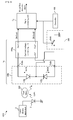
- FIG. 6 is a circuit diagram showing a configuration of the amplifier 240.
- the amplifier 240 is configured as an instrumentation amplifier, and it is provided with: operational amplifiers OP1, OP2, and OP3; feedback resistors R2, R3, and R6; a common input resistor R1; and input resistors R4, R5, and R7.
- the input terminal In- of the amplifier 240 is connected to a non-inverted input terminal (+) of the operational amplifier OP1.
- the input terminal In+ of the amplifier 240 is connected to a non-inverted input terminal (+) of the operational amplifier OP2.
- the operational amplifiers OP1 and OP2 are subject to negative feedback by the feedback resistors R2 and R3, respectively.
- the feedback resistors R2 and R3 are set to have an equal resistance value.
- the common input resistor R1 is connected between an inverted input terminal of the operational amplifier OP1 and an inverted input terminal of the operational amplifier OP2.
- the common input resistor R1 may function as a variable resistor for varying gain.
- An output terminal of the amplifier OP1 is connected to an inverted input terminal of the operational amplifier OP3 via the input resistor R4.
- An output terminal of the operational amplifier OP2 is connected to a non-inverted input terminal of the operational amplifier OP3 via the input resistor R5.
- One of terminals of the input resistor R7 is connected.
- the other terminal of the input resistor R7 is connected to the reference potential Vref, which is, for example, a GND potential.
- a voltage outputted from the operational amplifier OP2 is divided by the input resistors R5 and R7 and is inputted to the non-inverted input terminal of the operational amplifier OP3.
- the input resistors R4 and R5 are set to have an equal resistance value.
- the operational amplifier OP3 is subject to negative feedback by the feedback resistor R6.
- An output terminal of the operational amplifier OP3 is connected to the output terminal Out of the current/voltage converting unit 200c.
- the feedback resistor R6 and the input resistor R7 are set to have an equal resistance value.
- in-phase components e.g. hum noise
- the two voltage signals respectively outputted from the output terminal Out- and Out+ of the fully differential amplifier 230 are two differential signals which are differentially outputted in accordance with the detected current Idtc and which are different in polarity.
- the signal light component of the detected light is inputted in reverse phase.
- the signal light component of the detected light is reversed-phase, it is amplified by the amplifier 240 and is outputted as the light detection signal.
- the noise component can be reduced and the signal light component can be increased in the light detection signal, the S/N ratio can be significantly improved.
- a light detecting apparatus in a fourth example will be explained with reference to FIG. 7 .
- the light detecting apparatus in the fourth example is different from the light detecting apparatus 1c in the third example described above in that there is provided an amplifier 240d instead of the amplifier 240 in the third example described above with reference to FIG. 5 and FIG. 6 ; however, in other points, the light detecting apparatus in the fourth example is configured in substantially the same manner as the light detecting apparatus 1c in the third example described above.
- FIG. 7 is a circuit diagram showing a configuration of the amplifier in the fourth example.
- the same constituents as those in the third example shown in FIG. 5 and FIG. 6 will carry the same reference numerals, and the explanation thereof will be omitted, as occasion demands.
- the amplifier 240d is provided with: operational amplifiers OP1 and OP2; feedback resistors R2 and R3; a common input resistor R1; low pass filters (i.e. low-frequency pass filters) LPF1 and LPF2, and Analog to Digital (AD) converters ADC1 and ADC2.
- operational amplifiers OP1 and OP2 feedback resistors R2 and R3; a common input resistor R1; low pass filters (i.e. low-frequency pass filters) LPF1 and LPF2, and Analog to Digital (AD) converters ADC1 and ADC2.
- AD Analog to Digital
- the amplifier 240 in the third example described above with reference to FIG. 5 and FIG. 6 can output the light detection signal as a single end signal and as an analog signal.
- the amplifier 240d in the example is configured to output two differential signals which are different in polarity, as light detection signals DtOut1 and DtOut2.
- the light detection signals DtOut1 and DtOut2 are outputted as digital signals via the low pass filters LPF1 and LPF2 and the AD converters ADC1 and ADC2, respectively.
- an output signal of the operational amplifier OP1 is inputted to the AD converter ADC1 via the low pass filter LPF1 as an anti aliasing filter (i.e.
- a filter capable of removing aliasing noise generated by sampling performed by the AD converter and an output signal of the operational amplifier OP2 is inputted to the AD converter ADC2 via the low pass filter LPF2 as an anti aliasing filter.
- the S/N ratio can be increased in each of the light detection signals DtOut1 and DtOut2.
- a subtraction process may be performed by a signal processing apparatus (not illustrated) such as a digital signal processing apparatus like a Digital Signal Processor (DSP).
- DSP Digital Signal Processor
- the light detection signals DtOut1 and DtOut2 are quantized, it is resistant to noise from an outer world environment in the case of transmission performed via a communication network. Thus, it is possible to realize long distance transmission of the light detection signal.
- a blood flow measuring apparatus in a fifth example will be explained with reference to FIG. 8 .
- FIG. 8 is a block diagram showing a configuration of the blood flow measuring apparatus in the fifth example.
- the same constituents as those in the first example shown in FIG. 1 and FIG. 2 will carry the same reference numerals, and the explanation thereof will be omitted, as occasion demands.
- a blood flow measuring apparatus 1001 in the example is one example of the "fluid measuring apparatus" of the present invention, and is an apparatus for measuring volume of blood flow of a test object 900 which is a living body.
- the blood flow measuring apparatus 1001 is provided with: a laser driving apparatus 2; a semiconductor laser 3; the light detecting apparatus 1 in the first example described above with reference to FIG. 1 and FIG. 2 ; and a signal processing unit 5.
- the laser driving apparatus 2 and the semiconductor laser 3 are one example of the "irradiating unit” of the present invention
- the signal processing unit 5 is one example of the "calculating unit” of the present invention.
- the semiconductor laser 3 is driven by the laser driving apparatus 2, by which light from the semiconductor laser 3 is applied or irradiated to the test object 900.
- the light applied to the test object 900 is reflected or scattered by hemoglobin in blood capillaries of the test object 900.
- the light reflected or scattered in the test object 900 enters the optical current transducer unit 100 of the light detecting apparatus 1 (more specifically, the light receiving elements 110 and 120 described above with reference to FIG. 2 ).
- a detected current Idt is outputted from the optical current transducer unit 100.
- the detected current Idt is converted to a voltage signal by the current/voltage converting unit 200 and is inputted to the signal processing unit 5 as a light detection signal.
- the signal processing unit 5 calculates the volume of blood flow on the basis of the inputted light detection signal and outputs a digital signal including the volume of blood flow as a blood flow detection signal.
- the volume of blood flow can be calculated by the signal processing unit 5 on the basis of the light detection signal with a high S/N ratio.
- the volume of blood flow can be calculated accurately.
- the blood flow measuring apparatus may further provided with: two light detecting apparatuses each of which is configured in the same manner as the light detecting apparatus 1 in the first example described above; and a signal processing unit for calculating the volume of blood flow on the basis of a difference between light detection signals respectively outputted from the two light detecting apparatuses and for outputting a digital signal indicating the volume of blood flow as a blood flow detection signal.
- two light detecting apparatuses each of which is configured in the same manner as the light detecting apparatus 1 in the first example described above
- a signal processing unit for calculating the volume of blood flow on the basis of a difference between light detection signals respectively outputted from the two light detecting apparatuses and for outputting a digital signal indicating the volume of blood flow as a blood flow detection signal.
- a blood flow measuring apparatus in a sixth example will be explained with reference to FIG. 9 .
- FIG. 9 is a block diagram showing a configuration of the blood flow measuring apparatus in the sixth example.
- the same constituents as those in the second example shown in FIG. 4 and those in the fifth example shown in FIG. 8 will carry the same reference numerals, and the explanation thereof will be omitted, as occasion demands.
- a blood flow measuring apparatus 1002 in the example is one example of the "fluid measuring apparatus" of the present invention, and is an apparatus for measuring volume of blood flow of a test object 900 which is a living body.
- the blood flow measuring apparatus 1002 is provided with: a laser driving apparatus 2; a semiconductor laser 3; a light detecting apparatus 1g; and a signal processing unit 5g.
- the light detecting apparatus 1g is provided with: an optical current transducer unit 100b; and a current/voltage converting unit 200g.
- the optical current transducer unit 100b has light receiving elements 110b and 120b which are connected in series such that cathodes thereof are connected to each other.
- An anode of the light receiving element 110b is connected to an input terminal In1 of the current/voltage converting unit 200g via a terminal Pd1b
- an anode of the light receiving element 120b is connected to an input terminal In2 of the current/voltage converting unit 200g via a terminal Pd2b.
- a bias application selecting element 300 is connected between the light receiving elements 110b and 120b.
- the bias application selecting element 300 selects whether or not a bias voltage is applied to the light receiving elements 110b and 120b on the basis of a command from a controller 400.
- the bias application selecting element 300 is provided with an analog switch SW1.
- One end of the analog switch SW1 is connected between the light receiving elements 110b and 120b (i.e. at a connection point between the light receiving elements 110b and 120), and the other end of the analog switch SW1 is connected to a bias potential such as a GND potential.
- the bias application selecting element 300 switches between ON and OFF of the analog switch SW1 in accordance with the command from the controller 400, thereby selecting whether or not the bias voltage is applied to the light receiving elements 110b and 120b.
- the bias application selecting element 300 and the controller 400 are one example of the "bias application applying device" of the present invention.
- the current/voltage converting unit 200g is configured in substantially the same manner as the current/voltage converting unit provided for the light detecting apparatus described above with reference to FIG. 7 .
- the current/voltage converting unit 200g is provided with: a fully differential amplifier 230 (refer to FIG. 5 ); feedback resistors Rf1 and Rf2 (refer to FIG. 5 ); and an amplifier 240d (refer to FIG. 7 ).
- the current/voltage converting unit 200g outputs light detection signals DtOut1 and DtOut2 from output terminals Out1 and Out2.
- the signal processing unit 5g calculates the volume of blood flow on the basis of the inputted light detection signals DtOut1 and DtOut2 and outputs a digital signal indicating the volume of blood flow as a blood flow detection signal.
- the signal processing unit 5g changes the content of signal processing between at the time of bias application at which the bias voltage is applied to the light receiving elements 110b and 120b on the basis of the command from the controller 400 (i.e. when the analog switch SW1 is set to be ON) and at the time of opening at which the bias voltage is not applied to the light receiving elements 110b and 120b (when the analog switch SW1 is set to be OFF).
- the signal processing unit 5g adds the inputted light detection signals DtOut1 and DtOut2, thereby calculating a DC light power component.
- the signal processing unit 5g subtracts the inputted light detection signals DtOut1 and DtOut2, thereby calculating a power spectrum of a signal light component of a beat signal or the like and calculating the volume of blood flow of the test object 900 on the basis of the power spectrum.
- the signal processing unit 5g carries out standardization by dividing the volume of blood flow calculated at the time of opening by the DC light power component calculated at the time of bias application. This makes it possible to accurately measure the volume of blood flow of the test object 900 even if power fluctuation occurs in light emitted from the semiconductor laser 3.
- a blood flow measuring apparatus in a seventh example will be explained with reference to FIG. 10 .
- FIG. 10 is a block diagram showing a configuration of the blood flow measuring apparatus in the seventh example.
- the same constituents as those in the first example shown in FIG. 2 will carry the same reference numerals, and the explanation thereof will be omitted, as occasion demands.
- a light detecting apparatus 1h in the seventh example is different from the light detecting apparatus 1 in the first example described above in that there are further provided a light receiving element 130 and a current/voltage converting potion 203 for converting an electric current, which is outputted from the light receiving element 130, to a voltage; however, in other points, the light detecting apparatus 1h is configured in substantially the same manner as the light detecting apparatus 1 in the first example described above.
- the light receiving element 130 is one example of the "third photoelectric conversion element unit" of the present invention
- the current/voltage converting potion 203 is one example of the "second current/voltage converting unit" of the present invention.
- the light detecting apparatus 1h in the seventh example is provided with: an optical current transducer unit 100h; and a current/voltage converting unit 200h.
- the optical current transducer unit 100h has: light receiving elements 110 and 120 which are connected in parallel; and terminals Pd1 and Pd2, as in the optical current transducer unit 100 in the first example described above. Moreover, the optical current transducer unit 100h has: the light receiving element 130 provided separately from the light receiving elements 110 and 120; and terminals Pd1h and Pd2h.
- the light receiving element 130 is a photodiode such as a PIN diode, receives input light, and outputs an electric current in accordance with amount of the input light received.
- a cathode of the light receiving element 130 is connected to the terminal Pd1h, and an anode of the light receiving element 130 is connected to the terminal Pd2h.
- the terminals Pd1h and Pd2h are connected to input terminals In1 hand In2h of the current/voltage converting unit 200h described later, respectively.
- the current/voltage converting unit 200h has: input terminals In1 and In2; an operational amplifier 210; a feedback resistor Rf; and an output terminal OutA, in substantially the same manner as the current/voltage converting unit 200 in the first example described above.
- the output terminal OutA is connected to an output terminal of the operational amplifier 210.
- the output terminal OutA outputs a voltage signal outputted from the operational amplifier 210 as a light detection signal DtOutA.
- the current/voltage converting unit 200h has the current/voltage converting potion 203 for converting the electric current, which is outputted from the light receiving element 130, to the voltage.
- the current/voltage converting potion 203 has: the input terminals In1h and In2h; an operational amplifier 210h; a feedback resistor Rfh; and an output terminal OutB.
- the input terminal In1h is connected to an inverted input terminal (-) of the operational amplifier 210h.
- the input terminal In2h is connected to a non-inverted input terminal (+) of the operational amplifier 210h.
- the input terminal In2h and the non-inverted terminal of the operational amplifier 210h are grounded.
- the feedback resistor Rfh is connected between an output terminal of the operational amplifier 210h and the inverted input terminal of the operational amplifier 210h, performs negative feedback, and converts an electric current to a voltage. Since the negative feedback is performed by the feedback resistor Rfh, a potential difference between the inverted input terminal and the non-inverted input terminal of the operational amplifier 210h is almost zero (i.e. a so-called "imaginary short” is realized).
- the output terminal OutB is connected to the output terminal of the operational amplifier 210h.
- the output terminal OutB outputs a voltage signal outputted from the operational amplifier 210h as a light detection signal DtOutB.
- the light detecting apparatus 1h is provided with: the light receiving element 130; and the current/voltage converting portion 203 for converting the electric current, which is outputted from the light receiving element 130, to the voltage, a signal corresponding to a fixed light component of input light can be outputted as the light detection signal DtOutB on the basis of an electric current Idt3 outputted by the light receiving element 130.
- the light detection signal DtOutA it is possible to carry out signal standardization by dividing the light detection signal DtOutA based on a detected current Idt from the light receiving elements 110 and 120 which are connected in parallel (i.e.
- the light detection signal DtOutB (the signal corresponding to the fixed light component of the input light).
Abstract
Description
- The present invention relates to, for example, a light detecting apparatus for detecting a signal light component included in light which is reflected, scattered, or the like by a test object, a specimen, or an object to be examined, and a fluid measuring apparatus, such as a laser Doppler blood flowmeter, provided with the light detecting apparatus.
- As this type of light detecting apparatus, for example, there is an apparatus used as a light receiving unit for detecting light from a living body on a laser Doppler blood flowmeter (e.g. refer to
patent documents 1 and 2). The laser Doppler blood flowmeter irradiates the living body with light such as laser light, and calculates blood flow velocity or the like of the living body from a change in wavelength due to a Doppler shift in the light reflection or scattering. The light detecting apparatus used as the light receiving unit of the laser Doppler blood flowmeter is typically provided with: a photoelectric conversion element such as a photodiode; and a current/voltage conversion circuit including an operational amplifier (i.e. "operational amplification circuit") for amplifying an output electric current of the photoelectric conversion element and converting it to a voltage signal. - On the other hand, for example, a patent document 3 discloses that on a light receiving circuit used for optical communication or the like, bias elements are connected to both ends of a photodiode and the both ends are connected to an input end of a differential amplifier (operational amplifier) via a condenser and that resistive elements are provided between a positive output and a negative input and between an inverted output and a positive input of the differential.
-
- Patent document 1: Japanese Patent Application Laid Open No.
2007-175415 - Patent document 2: Japanese Patent No.
3313841 - Patent document 3: Japanese Patent Application Laid Open No.
Hei 6-224652 - If this type of light detecting apparatus is used as the light receiving unit of the laser Doppler blood flowmeter as described above, there is such a technical problem that it is hard to accurately detect a signal light component because intensity of the signal light component included in the light reflected or scattered by the living body (i.e. a Doppler-shifted modulation component) is less than that of a fixed light component included in the light reflected or scattered by the living body (i.e. a component which is not changed by the reflection or scattering by the living body).
- In view of the aforementioned problems, it is therefore an object of the present invention to provide a light detecting apparatus capable of accurately detecting a signal light component included in light which is reflected, scattered, or the like by a test object, and a fluid measuring apparatus provided with such a light detecting apparatus.
- The above object of the present invention can be achieved by a light detecting apparatus for detecting a signal light component included in input light, the light detecting apparatus provided with: an optical current transducer unit which includes first and second photoelectric conversion element units each converting the input light to an electric current and outputting it, and which outputs a differential current between an electric current outputted by the first photoelectric conversion element unit and an electric current outputted by the second photoelectric conversion element unit as a detected current; and a first current/voltage converting unit which amplifies the detected current outputted from the optical current transducer unit, converts it to a voltage signal, and outputs the voltage signal.
- The above object of the present invention can be also achieved by a fluid measuring apparatus provided with: an irradiating unit for irradiating a test object with light; the light detecting apparatus of the present invention described above to which light from the test object due to the irradiated light is inputted as the input light; and a calculating unit for calculating fluid information about a fluid in the test object on the basis of the voltage signal outputted by the first current/voltage converting unit.
- The operation and other advantages of the present invention will become more apparent from Mode for Carrying Out the Invention explained below.
-
- [
FIG. 1] FIG. 1 is a block diagram conceptually showing an entire configuration of a light detecting apparatus in a first example. - [
FIG. 2] FIG. 2 is a block diagram showing a configuration of the light detecting apparatus in the first example. - [
FIG. 3] FIG. 3 is a waveform chart showing one example of each of a detected current Idt outputted from an optical current transducer unit of the light detecting apparatus in the first example and an output voltage Vout of an operational amplifier provided for a current/voltage converting unit. - [
FIG. 4] FIG. 4 is a block diagram showing a configuration of a light detecting apparatus in a second example. - [
FIG. 5] FIG. 5 is a block diagram showing a configuration of a light detecting apparatus in a third example. - [
FIG. 6] FIG. 6 is a circuit diagram showing a configuration of an amplifier provided for the light detecting apparatus in the third example. - [
FIG. 7] FIG. 7 is a circuit diagram showing a configuration of an amplifier provided for a light detecting apparatus in a fourth example. - [
FIG. 8] FIG. 8 is a block diagram showing a configuration of a blood flow measuring apparatus in a fifth example. - [
FIG. 9] FIG. 9 is a block diagram showing a configuration of a blood flow measuring apparatus in a sixth example. - [
FIG. 10] FIG. 10 is a circuit diagram showing a configuration of a light detecting apparatus in a seventh example. - Hereinafter, embodiments of the present invention will be explained.
- The above object according to a first embodiment can be achieved by a light detecting apparatus for detecting a signal light component included in input light, the light detecting apparatus provided with: an optical current transducer unit which includes first and second photoelectric conversion element units each converting the input light to an electric current and outputting it, and which outputs a differential current between an electric current outputted by the first photoelectric conversion element unit and an electric current outputted by the second photoelectric conversion element unit as a detected current; and a first current/voltage converting unit which amplifies the detected current outputted from the optical current transducer unit, converts it to a voltage signal, and outputs the voltage signal.
- According to the light detecting apparatus in the first embodiment, in its operation, for example, light which is reflected, scattered, or the like by a test object, a specimen, or an object to be examined is inputted to the optical current transducer unit as the input light. The input light inputted to the optical current transducer unit is transduced by the optical current transducer unit to the electric current and is outputted as the detected current. The detected current outputted from the optical current transducer unit is amplified with a predetermined gain by the first current/voltage converting unit including, for example, an operational amplifier and a negative feedback resistor, and is converted to the voltage signal. On the basis of the voltage signal outputted by the first current/voltage converting unit, the signal light component included in the input light (e.g. a modulation component by the reflection, scattering, or the like in the test object) can be detected.
- Particularly in the embodiment, the optical current transducer unit includes the first and second photoelectric conversion element units each converting the input light to the electric current and outputting it, and outputs the differential current between the electric current outputted by the first photoelectric conversion element unit and the electric current outputted by the second photoelectric conversion element unit as the detected current.
- Specifically, each of the first and second photoelectric conversion element units is composed of one or a plurality of photoelectric conversion element units (e.g. photodiodes, etc.) and outputs the electric current in accordance with amount of the input light. The optical current transducer unit outputs the differential current between the electric current outputted by the first photoelectric conversion element unit and the electric current outputted by the second photoelectric conversion element unit as the detected current. For example, the first and second photoelectric conversion element units are connected in parallel such that a cathode of the first photoelectric conversion element unit and an anode of the second photoelectric conversion element unit are connected and such that an anode of the first photoelectric conversion element unit and a cathode of the second photoelectric conversion element unit are connected. Incidentally, the cathode of the first photoelectric conversion element unit means an electrode into which the electric current flows from the exterior when the input light is inputted to the first photoelectric conversion element unit, and the anode of the first photoelectric conversion element unit means an electrode from which the electric current flows out to the exterior when the input light is inputted to the first photoelectric conversion element unit. In the same manner, the cathode of the second photoelectric conversion element unit means an electrode into which the electric current flows from the exterior when the input light is inputted to the second photoelectric conversion element unit, and the anode of the second photoelectric conversion element unit means an electrode from which the electric current flows out to the exterior when the input light is inputted to the second photoelectric conversion element unit. Alternatively, for example, the first and second photoelectric conversion element units are connected in series such that cathodes thereof or anodes thereof are connected to each other.
- Thus, of the electric current outputted from each of the first and second photoelectric conversion element units, an electric current component corresponding to a fixed light component included in the input light (hereinafter referred to as a direct current (DC) component as occasion demands) can be reduced or eliminated, and an electric current component corresponding to the signal light component included in the input light (hereinafter referred to as an alternate or alternating current (AC) component as occasion demands) can be outputted as the detected current. In other words, it is possible to cancel the DC component of the electric current outputted from the first photoelectric conversion element unit and the DC component of the electric current outputted from the second photoelectric conversion element unit, and it is also possible to output the detected current mainly including the AC component corresponding to the signal light component included in the input light.
- Therefore, it is possible to increase the gain when the detected current is amplified and converted to the voltage signal by the first current/voltage converting unit. In other words, according to the embodiment, as described above, since the DC component of the electric current outputted from the first photoelectric conversion element unit and the DC component of the electric current outputted from the second photoelectric conversion element unit are canceled and the detected current hardly includes or does not include the DC component at all, it is possible to increase the gain of the amplification by the first current/voltage converting unit while avoiding occurrence of a saturation phenomenon of the first current/voltage converting unit which can occur, for example, if the DC component included in the detected current is relatively large (e.g. a saturation phenomenon of an operational amplifier included in the first current/voltage converting unit). Incidentally, the saturation phenomenon of the first current/voltage converting unit means such a phenomenon that the voltage signal outputted by the first current/voltage converting unit becomes a constant saturation voltage determined in accordance with a power supply voltage of the first current/voltage converting unit regardless of a current value of the detected current if the current value of the detected current inputted to the first current/voltage converting unit is greater than a predetermined current value.
- Moreover, according to the embodiment, as described above, since the electric current mainly including the AC component corresponding to the signal light component included in the input light can be outputted as the detected current, it is possible to improve a signal-to-noise (S/N) ratio in the voltage signal outputted by the first current/voltage converting unit. In other words, according to the embodiment, of the electric current outputted from each of the first and second photoelectric conversion element units, the DC component corresponding to a noise component included in the input light as the fixed light component is reduced or eliminated, and the detected current mainly including the AC component corresponding to the signal light component is outputted. Thus, it is possible to improve the S/N ratio in the voltage signal outputted by the first current/voltage converting unit.
- As a result, according to the light detecting apparatus in the embodiment, the signal light component included in the input light can be detected, accurately.
- In one aspect of the light detecting apparatus in the first embodiment, the first and second photoelectric conversion element units are connected in parallel such that a cathode of the first photoelectric conversion element unit and an anode of the second photoelectric conversion element unit are connected and such that an anode of the first photoelectric conversion element unit and a cathode of the second photoelectric conversion element unit are connected.
- According to this aspect, the differential current between the electric current outputted by the first photoelectric conversion element unit and the electric current outputted by the second photoelectric conversion element unit can be certainly outputted as the detected current.
- In another aspect of the light detecting apparatus in the first embodiment, the first and second photoelectric conversion element units are connected in series such that cathodes thereof or anodes thereof are connected to each other.
- According to this aspect, the differential current between the electric current outputted by the first photoelectric conversion element unit and the electric current outputted by the second photoelectric conversion element unit can be certainly outputted as the detected current.
- In the aspect in which the first and second photoelectric conversion element units are connected in series, the light detecting apparatus is further provided with a bias voltage applying device which is connected between the first and second photoelectric conversion element units connected in series and which can apply a bias voltage to each of the first and second photoelectric conversion element units, and the optical current transducer unit outputs each of the electric current outputted by the first photoelectric conversion element unit and the electric current outputted by the second photoelectric conversion element unit if the bias voltage is applied to each of the first and second photoelectric conversion element units by the bias voltage applying device.
- In this case, it is possible to detect the DC component of each of the electric current outputted by the first photoelectric conversion element unit and the electric current outputted by the second photoelectric conversion element unit. Thus, it is possible to calculate a ratio of the signal light component with respect to the fixed light component included in the input light. Therefore, the signal light component included in the input light can be detected, more accurately.
- In another aspect of the light detecting apparatus in the first embodiment, it is further provided with: a third photoelectric conversion element unit for converting the input light to an electric current and outputting it; and a second current/voltage converting unit for amplifying the electric current outputted from the third photoelectric conversion element unit and converting it to a voltage signal.
- According to this aspect, on the basis of the voltage signal outputted from the second current/voltage converting unit, the DC component of the electric current outputted by the third photoelectric conversion element unit can be detected. Thus, it is possible to calculate the ratio of the signal light component with respect to the fixed light component included in the input light. Therefore, the signal light component included in the input light can be detected, more accurately.
- In another aspect of the light detecting apparatus in the first embodiment, the optical current transducer unit has first and second terminals which are connected to both ends of the first and second photoelectric conversion element units, respectively, and the first current/voltage converting unit has: a fully differential amplifier having a positive input terminal connected to the first terminal, a negative input terminal connected to the second terminal, a negative output terminal for inverting, amplifying, and outputting a signal inputted to the positive input terminal, and a positive output terminal for inverting, amplifying, and outputting a signal inputted to the negative input terminal; a first negative feedback resistor connected between the positive input terminal and the negative output terminal; a second negative feedback resistor connected between the negative input terminal and the positive output terminal; and an amplifier for amplifying a difference between a signal outputted from the positive output terminal and a signal outputted from the negative output terminal and for outputting it as a voltage signal.
- According to this aspect, the first and second photoelectric conversion element units, such as photodiodes, can be operated in a condition that a reverse bias voltage is hardly or not applied at all, i.e. in a so-called power generation mode. Thus, it is possible to reduce or eliminate a dark current generated in the first and second photoelectric conversion element units (i.e. an opposite direction current generated by the reverse bias voltage even without the input light inputted). This makes it possible to reduce a noise current due to fluctuation of the dark current and to improve the S/N ratio in the voltage signal outputted by the amplifier of the first current/voltage converting unit. As a result, the signal light component included in the input light can be detected, more accurately.
- The above object according to the first embodiment can be also achieved by a fluid measuring apparatus provided with: an irradiating unit for irradiating a test object with light; the light detecting apparatus according to the aforementioned embodiment (including its various aspects) to which light from the test object due to the irradiated light is inputted as the input light; and a calculating unit for calculating fluid information about a fluid in the test object on the basis of the voltage signal outputted by said first current/voltage converting unit.
- According to the fluid measuring apparatus in the embodiment, since it is provided with the light detecting apparatus according to the aforementioned embodiment, it is possible to accurately calculate the fluid information about the fluid in the test object.
- Hereinafter, examples of the present invention will be explained with reference to the drawings.
- A light detecting apparatus in a first example will be explained with reference to
FIG. 1 to FIG. 3 . - Firstly, a configuration of the light detecting apparatus in the first example will be explained with reference to
FIG. 1 andFIG. 2 . -
FIG. 1 is a block diagram conceptually showing an entire configuration of the light detecting apparatus in the first example.FIG. 2 is a block diagram showing a configuration of the light detecting apparatus in the first example. - In
FIG. 1 andFIG. 2 , alight detecting apparatus 1 in the first example is a light detecting apparatus for detecting a signal light component included in input light inputted from the exterior, which is provided with: an opticalcurrent transducer unit 100; and a current/voltage converting unit 200. The input light is, for example, light obtained by that laser light is reflected, scattered, or the like by a test object, a specimen, or an object to be examined (e.g. a human finger, etc.) and includes the signal light component indicating information about the test object (e.g. a modulation component by the reflection, scattering, or the like in the test object). - In
FIG. 2 , the opticalcurrent transducer unit 100 haslight receiving elements light receiving element 110 is one example of the "first photoelectric conversion element unit" of the present invention, and thelight receiving element 120 is one example of the "second photoelectric conversion element unit" of the present invention. - Each of the
light receiving elements light receiving elements light receiving element 110 and the cathode of thelight receiving element 120 are connected to the terminal Pd1, and the cathode of thelight receiving element 110 and the anode of thelight receiving element 120 are connected to the terminal Pd2. Since thelight receiving elements current transducer unit 100 can output a differential current between an electric current Idt1 outputted by thelight receiving element 110 and an electric current Idt2 outputted by thelight receiving element 120 as a detected current Idt from the terminal Pd1. - The terminals Pd1 and Pd2 are connected to input terminals In1 and In2 of the current/
voltage converting unit 200 described later, respectively. - The current/
voltage converting unit 200 has: the input terminals In1 and In2; anoperational amplifier 210; a feedback resistor Rf; and an output terminal Out. The current/voltage converting unit 200 is configured as a transimpedance amplifier (current-voltage conversion amplifier) for converting an electric current inputted to the input terminal In1 to a voltage signal and outputting it. The current/voltage converting unit 200 converts the detected current Idt, which is inputted to the input terminal In1 from the opticalcurrent transducer unit 100, to the voltage signal and outputs it as a light detection signal from the output terminal Out. - The input terminal In1 is connected to an inverted input terminal (-) of the
operational amplifier 210. The input terminal In2 is connected to a non-inverted input terminal (+) of theoperational amplifier 210. The input terminal In2 and the non-inverted input terminal of theoperational amplifier 210 are grounded (i.e. connected to a reference potential such as a ground (GND) potential). - The feedback resistor Rf is connected between an output terminal of the
operational amplifier 210 and the inverted input terminal of theoperational amplifier 210, performs negative feedback, and converts an electric current to a voltage. Since the negative feedback is performed by the feedback resistor Rf, a potential difference between the inverted input terminal and the non-inverted input terminal of theoperational amplifier 210 is almost zero (i.e. a so-called "imaginary short" is realized). - The output terminal Out is connected to the output terminal of the
operational amplifier 210. The output terminal Out outputs the voltage signal outputted from theoperation amplifier 210 as the light detection signal. - Next, operations of the light detecting apparatus in the example will be explained with reference to
FIG. 2 . - In
FIG. 2 , in operation of thelight detecting apparatus 1, if the input light is received by each of thelight receiving elements light receiving elements light receiving element 110 outputs the electric current Idt1 in accordance with the amount of the input light received, and thelight receiving element 120 outputs the electric current Idt2 in accordance with the amount of the input light received. Then, as described above, since thelight receiving elements light receiving element 110 and the anode of thelight receiving element 120 are connected to each other and such that the anode of thelight receiving element 110 and the cathode of thelight receiving element 120 are connected to each other, the differential current between the electric current Idt1 outputted from thelight receiving element 110 and the electric current Idt2 outputted from thelight receiving element 120 is outputted as the detected current Idt from the terminal Pd1. - Here, the input light includes the signal light component (e.g. the modulation component by the reflection, scattering, or the like in the test object) and a fixed light component (e.g. a noise component and a component according to the amount of the laser light applied or irradiated to the test object). Thus, each of the electric current Idt1 outputted by the
light receiving element 110 and the electric current Idt2 outputted by thelight receiving element 120 includes an AC component which is an electric current component corresponding to the signal light component included in the input light and a DC component which is an electric current component corresponding to the fixed light component included in the input light. The signal light component of the input light inputted to thelight receiving element 110 and the signal light component of the input light inputted to thelight receiving element 120 have mutually different optical paths because a position at which thelight receiving element 110 is placed and a position at which thelight receiving element 120 is placed are different from each other. Thus, the electric current components corresponding to the signal light components are signals having a low correlation with each other. Thus, the AC component of the electric current Idt1 outputted by the light receiving element 110 (i.e. the electric current component corresponding to the signal light component) and the AC component of the electric current Idt2 outputted by thelight receiving element 120 have a low correlation with each other. In other words, the AC components of the electric currents Idt1 and Idt2 include many out-of-phase components having mutually different phases, amplitudes, and frequencies (in other words, uncorrelated components having a low correlation with one another). On the other hand, the DC component of the electric current Idt1 outputted by the light receiving element 110 (i.e. the electric current component corresponding to the fixed light component) and the DC component of the electric current Idt2 outputted by thelight receiving element 120 have substantially the same amplitude if light receiving areas are set to be the same. In other words, the DC components of the electric currents Idt1 and Idt2 have in-phase components (in other words, correlated components having a strong correlation with each other). - Thus, as shown in
FIG. 3 , the detected current Idt, which is the differential current between the electric current Idt1 outputted from thelight receiving element 110 and the electric current Idt2 outputted from thelight receiving element 120, is an electric current which increases in comparison with the AC components of the electric currents Idt1 and Idt2 and in which the DC component is reduced or eliminated. Subtraction of signals including many uncorrelated components is equivalent to subtraction of random signals, and a signal power increases after the subtraction. Incidentally,FIG. 3 is a waveform chart showing one example of each of the detected current Idt and an output voltage Vout of theoperational amplifier 210. - In other words, according to the optical
current transducer unit 100, it is possible to cancel the DC component of the electric current Idt1 outputted by thelight receiving element 110 and the DC component of the electric current Idt2 outputted by thelight receiving element 120, and it is possible to output the detected current Idt mainly including the AC component corresponding to the signal light component included in the input light. - Therefore, it is possible to increase gain when the detected current Idt is amplified and converted to the voltage signal by the current/
voltage converting unit 200. Saying it differently, according to the example, as described above, since the DC component of the electric current Idt1 outputted by thelight receiving element 110 and the DC component of the electric current Idt2 outputted by thelight receiving element 120 are canceled and the detected current Idt hardly includes or does not include the DC component at all, it is possible to increase the gain of the amplification by the current/voltage converting unit 200 while avoiding occurrence of a saturation phenomenon of theoperational amplifier 210 included in the current/voltage converting unit 200 which can occur, for example, if the DC component included in the detected current Idt is relatively large. In other words, inFIG. 3 , it is possible to increase the gain of the amplification by the current/voltage converting unit 200 while maintaining a relatively large difference ΔV1 between a maximum value of the output voltage Vout of theoperational amplifier 210 and a saturation voltage Vs of theoperational amplifier 210. - Moreover, according to the example, as described above, since the optical
current transducer unit 100 can output, as the detected current Idt, an electric current mainly including the AC component corresponding to the signal light component included in the input light, it is possible to improve an S/N ratio in the light detection signal outputted by the current/voltage converting unit 200. In other words, according to the example, the DC component corresponding to the noise component included as the fixed light component in the input light (e.g. the noise component due to fluctuation of a laser light source) is reduced or eliminated from the electric current Idt1 outputted by thelight receiving element 110 and the electric current Idt2 outputted by thelight receiving element 120, and the detected current Idt mainly including the AC component corresponding to the signal light component is outputted. Thus, it is possible to improve the S/N ratio in the light detection signal outputted by the current/voltage converting unit 200. - In addition, according to the example, as described above, the imaginary short is realized in which the potential difference between the inverted input terminal and the non-inverted input terminal of the
operational amplifier 210 is almost zero. Thus, a potential difference between the terminal Pd1 connected to the inverted input terminal of theoperational amplifier 210 via the input terminal In1 and the terminal Pd2 connected to the non-inverted input terminal of theoperational amplifier 210 via the input terminal In2 is also almost zero, and each of thelight receiving elements light receiving elements voltage converting unit 200. - According to the example, the DC component included as the fixed light component in the input light can be reduced or eliminated, and a ratio of the output voltage Vout as the output with respect to the detected current Idt as the input, i.e. a conversion gain, can be increased while the saturation phenomenon is avoided on the current/
voltage converting unit 200. Thus, the S/N ratio can be improved. - Specifically, even if a resistance value of the feedback resistor Rf in
FIG. 2 is set high, the saturation phenomenon of theoperational amplifier 210 can be avoided. As one of main components of noise generated by the current/voltage converting unit 200, thermal noise of the feedback resistor Rf is well known. The thermal noise is proportional to the square root of the resistance value of the feedback resistor Rf. On the other hand, since the conversion gain is proportional to the resistance value of the feedback resistor Rf, if the resistance value of the feedback resistor Rf is set high, the S/N ratio is improved in multiples of the square root of the resistance value of the feedback resistor Rf. However, if the resistance value of the feedback resistor Rf is set high in a conventional simple photodiode configuration, theoperational amplifier 210 is saturated by the DC component. If theoperational amplifier 210 is saturated, the signal light component is not outputted, which causes fatal problems. On the other hand, according to the example, since the DC component can be reduced or eliminated at a stage of the detected current Idt, theoperational amplifier 210 is not saturated even if the resistance value of the feedback resistor Rf is set high. Therefore, according to the example, it is possible to avoid the saturation of theoperational amplifier 210 and to set the high S/N ratio by the high conversion gain at the same time. - As explained above, according to the
light detecting apparatus 1 in the example, it is possible to improve the S/N ratio in the light detection signal outputted by the current/voltage converting unit 200. As a result, the signal light component included in the input light can be detected accurately. - A light detecting apparatus in a second example will be explained with reference to
FIG. 4 . -
FIG. 4 is a block diagram showing a configuration of the light detecting apparatus in the second example. Incidentally, inFIG. 4 , the same constituents as those in the first example shown inFIG. 2 will carry the same reference numerals, and the explanation thereof will be omitted, as occasion demands. - In
FIG. 4 , alight detecting apparatus 1b in the second example is different from thelight detecting apparatus 1 in the first example described above in that there is provided an opticalcurrent transducer unit 100b instead of the opticalcurrent transducer unit 100 in the first example described above; however, in other points, thelight detecting apparatus 1b is configured in substantially the same manner as thelight detecting apparatus 1 in the first example described above. - In
FIG. 4 , the opticalcurrent transducer unit 100b haslight receiving elements light receiving element 110b is one example of the "first photoelectric conversion element unit" of the present invention, and thelight receiving element 120b is one example of the "second photoelectric conversion element unit" of the present invention. - Each of the
light receiving elements light receiving elements light receiving element 110b is connected to the terminal Pd1b, and an anode of thelight receiving element 120b is connected to the terminal Pd2b. Since thelight receiving elements current transducer unit 100b can output a differential current between an electric current Idt1b outputted by thelight receiving element 110b and an electric current Idt2b outputted by thelight receiving element 120b as a detected current Idtb from the terminal Pd1b. - The terminals Pd1b and Pd2b are connected to input terminals In1 and In2 of the current/
voltage converting unit 200, respectively. - By virtue of the
light detecting apparatus 1b configured in this manner, it is possible to receive the same benefits as those obtained by thelight detecting apparatus 1 in the first example described above. In other words, it is possible to cancel a DC component of the electric current Idt1b outputted by thelight receiving element 110b and a DC component of the electric current Idt2b outputted by thelight receiving element 120b, and it is possible to output the detected current Idtb mainly including an AC component corresponding to a signal light component included in the input light. As a result, it is possible to improve an S/N ratio in a light detection signal outputted by the current/voltage converting unit 200. - A light detecting apparatus in a third example will be explained with reference to
FIG. 5 andFIG. 6 . -
FIG. 5 is a block diagram showing a configuration of the light detecting apparatus in the third example. - In
FIG. 5 , alight detecting apparatus 1c in the third example is a light detecting apparatus for detecting a signal light component included in input light inputted from the exterior, which is provided with: an opticalcurrent transducer unit 100c; and a current/voltage converting unit 200c. The input light is, for example, light obtained by that laser light is reflected, scattered, or the like by a test object, a specimen, or an object to be examined (e.g. a human finger, etc.) and includes the signal light component indicating information about the test object (e.g. a modulation component by the reflection, scattering, or the like in the test object). - In
FIG. 5 , the opticalcurrent transducer unit 100c haslight receiving elements light receiving element 110c is one example of the "first photoelectric conversion element unit" of the present invention, and thelight receiving element 120c is one example of the "second photoelectric conversion element unit" of the present invention. - Each of the
light receiving elements light receiving elements light receiving element 110c is connected to the terminal Pd1c, and a cathode of thelight receiving element 120c is connected to the terminal Pd2c. Since thelight receiving elements current transducer unit 100c can output a differential current (Idt2c-Idtlc) between an electric current Idt1c outputted by thelight receiving element 110c and an electric current Idt2c outputted by thelight receiving element 120c as a detected current Idtc from the terminal Pd1c. Moreover, the opticalcurrent transducer unit 100c can output from the terminal Pd2c an electric current (-Idtc) in which a polarity of the detected current Idtc outputted from the terminal Pd1c is reversed. - The terminals Pd1c and Pd2c are connected to input terminals In1c and In2c of the current/
voltage converting unit 200c, respectively. - According to the current/
voltage converting unit 200c configured in this manner, it is possible to cancel a DC component of the electric current Idt1c outputted by thelight receiving element 110c and a DC component of the electric current Idt2c outputted by thelight receiving element 120c, and it is possible to output the detected current Idtc mainly including an AC component corresponding to a signal light component included in the input light. As a result, it is possible to improve an S/N ratio in a light detection signal outputted by the current/voltage converting unit 200c. - The current/
voltage converting unit 200c has: the input terminals In1c and In2c; a fullydifferential amplifier 230 as one example of the "fully differential amplifier" of the present invention; feedback resistors Rf1 and Rf2; anamplifier 240; and an output terminal Out. The fullydifferential amplifier 230 converts the electric current Idtc, which is inputted to the input terminal In1c, to a voltage signal -Rf1*Idtc and outputs it from an output terminal Out-. At the same time, the fullydifferential amplifier 230 converts the electric current -Idtc, which is inputted to the input terminal In2c, to a voltage signal Rf2*Idtc and outputs it from an output terminal Out+. In other words, the fullydifferential amplifier 230 is configured as a transimpedance amplifier for independently current/voltage-converting the electric currents inputted to the input terminals In1c and In2c and differentially outputting them. - The current/
voltage converting unit 200c converts the detected current Idtc, which is inputted to the input terminal In1 from the opticalcurrent transducer unit 100c, to the voltage signal and outputs it as the light detection signal from the output terminal Out. - The fully
differential amplifier 230 is a fully differential amplifier having: an input terminal In+ connected to the input terminal In1c; an input terminal Inconnected to the input terminal In2c; the output terminal Out-; and the output terminal Out+. A reference potential is inputted via a reference potential terminal Vref. The Output terminals Out- and Out+ are connected to input terminals In- and In+ of theamplifier 240 described later, respectively. - The feedback resistor Rf1 is connected between the input terminal In+ of the fully
differential amplifier 230 and the output terminal Out- of the fullydifferential amplifier 230, performs negative feedback and converts an electric current to a voltage. The feedback resistor Rf2 is connected between the input terminal In- of the fullydifferential amplifier 230 and the output terminal Out+ of the fullydifferential amplifier 230, performs negative feedback and converts an electric current to a voltage. Since the negative feedback is performed by the feedback resistors Rf1 and Rf2, a potential difference between the input terminal In+ and the reference potential terminal Vref of the fullydifferential amplifier 230 is almost zero. In the same manner, a potential difference between the input terminal In- and the reference potential terminal Vref is almost zero. As a result, the input terminal In+ and the input terminal In- have almost the same potential. Thus, a potential difference between the terminal Pd1c connected to the input terminal In+ of the fullydifferential amplifier 230 via the input terminal In1c and the terminal Pd2c connected to the input terminal In- of the fullydifferential amplifier 230 via the input terminal In2c is almost zero, and each of thelight receiving elements light receiving elements voltage converting unit 200c. - The
amplifier 240 is an amplifier for amplifying and outputting apotential difference 2*Rf*Idtc (selected such that Rfl=Rf2=Rf) between the voltage signal -Rf1*Idtc inputted from the input terminal In- and the voltage signal Rf2*Idtc inputted from the input terminal In+. An output terminal of theamplifier 240 is connected to the output terminal Out of the current/voltage converting unit 200c. -
FIG. 6 is a circuit diagram showing a configuration of theamplifier 240. - In
FIG. 6 , theamplifier 240 is configured as an instrumentation amplifier, and it is provided with: operational amplifiers OP1, OP2, and OP3; feedback resistors R2, R3, and R6; a common input resistor R1; and input resistors R4, R5, and R7. - The input terminal In- of the
amplifier 240 is connected to a non-inverted input terminal (+) of the operational amplifier OP1. The input terminal In+ of theamplifier 240 is connected to a non-inverted input terminal (+) of the operational amplifier OP2. The operational amplifiers OP1 and OP2 are subject to negative feedback by the feedback resistors R2 and R3, respectively. - The feedback resistors R2 and R3 are set to have an equal resistance value.
- The common input resistor R1 is connected between an inverted input terminal of the operational amplifier OP1 and an inverted input terminal of the operational amplifier OP2. Incidentally, the common input resistor R1 may function as a variable resistor for varying gain.
- An output terminal of the amplifier OP1 is connected to an inverted input terminal of the operational amplifier OP3 via the input resistor R4. An output terminal of the operational amplifier OP2 is connected to a non-inverted input terminal of the operational amplifier OP3 via the input resistor R5. Between the input resistor R5 and the non-inverted input terminal of the operational amplifier OP3, one of terminals of the input resistor R7 is connected. The other terminal of the input resistor R7 is connected to the reference potential Vref, which is, for example, a GND potential. A voltage outputted from the operational amplifier OP2 is divided by the input resistors R5 and R7 and is inputted to the non-inverted input terminal of the operational amplifier OP3.
- The input resistors R4 and R5 are set to have an equal resistance value.
- The operational amplifier OP3 is subject to negative feedback by the feedback resistor R6. An output terminal of the operational amplifier OP3 is connected to the output terminal Out of the current/
voltage converting unit 200c. - The feedback resistor R6 and the input resistor R7 are set to have an equal resistance value.
- According to the
amplifier 240 configured in this manner, in-phase components (e.g. hum noise) in the two voltage signals respectively outputted from the output terminal Out- and Out+ of the fullydifferential amplifier 230 can be removed as noise. Moreover, the two voltage signals respectively outputted from the output terminal Out- and Out+ of the fullydifferential amplifier 230 are two differential signals which are differentially outputted in accordance with the detected current Idtc and which are different in polarity. Thus, to the input terminals In+ and In- of theamplifier 240, the signal light component of the detected light is inputted in reverse phase. By this, the in-phase components such as hum noise can be removed as the noise from a voltage signal outputted as a light detection signal by theamplifier 240. In addition, since the signal light component of the detected light is reversed-phase, it is amplified by theamplifier 240 and is outputted as the light detection signal. As a result, since the noise component can be reduced and the signal light component can be increased in the light detection signal, the S/N ratio can be significantly improved. - A light detecting apparatus in a fourth example will be explained with reference to
FIG. 7 . - The light detecting apparatus in the fourth example is different from the
light detecting apparatus 1c in the third example described above in that there is provided anamplifier 240d instead of theamplifier 240 in the third example described above with reference toFIG. 5 andFIG. 6 ; however, in other points, the light detecting apparatus in the fourth example is configured in substantially the same manner as thelight detecting apparatus 1c in the third example described above. -
FIG. 7 is a circuit diagram showing a configuration of the amplifier in the fourth example. Incidentally, inFIG. 7 , the same constituents as those in the third example shown inFIG. 5 andFIG. 6 will carry the same reference numerals, and the explanation thereof will be omitted, as occasion demands. - In
FIG. 7 , theamplifier 240d is provided with: operational amplifiers OP1 and OP2; feedback resistors R2 and R3; a common input resistor R1; low pass filters (i.e. low-frequency pass filters) LPF1 and LPF2, and Analog to Digital (AD) converters ADC1 and ADC2. - The
amplifier 240 in the third example described above with reference toFIG. 5 andFIG. 6 can output the light detection signal as a single end signal and as an analog signal. In contrast, as shown inFIG. 7 , theamplifier 240d in the example is configured to output two differential signals which are different in polarity, as light detection signals DtOut1 and DtOut2. In addition, the light detection signals DtOut1 and DtOut2 are outputted as digital signals via the low pass filters LPF1 and LPF2 and the AD converters ADC1 and ADC2, respectively. According to theamplifier 240d, an output signal of the operational amplifier OP1 is inputted to the AD converter ADC1 via the low pass filter LPF1 as an anti aliasing filter (i.e. a filter capable of removing aliasing noise generated by sampling performed by the AD converter) and an output signal of the operational amplifier OP2 is inputted to the AD converter ADC2 via the low pass filter LPF2 as an anti aliasing filter. Thus, the S/N ratio can be increased in each of the light detection signals DtOut1 and DtOut2. With regard to the light detection signals DtOut1 and DtOut2 which are output signals of the AD converters ADC1 and ADC2 and which are quantized, a subtraction process may be performed by a signal processing apparatus (not illustrated) such as a digital signal processing apparatus like a Digital Signal Processor (DSP). - As a result, according to the example, since the light detection signals DtOut1 and DtOut2 are quantized, it is resistant to noise from an outer world environment in the case of transmission performed via a communication network. Thus, it is possible to realize long distance transmission of the light detection signal.
- A blood flow measuring apparatus in a fifth example will be explained with reference to
FIG. 8 . -
FIG. 8 is a block diagram showing a configuration of the blood flow measuring apparatus in the fifth example. Incidentally, inFIG. 8 , the same constituents as those in the first example shown inFIG. 1 andFIG. 2 will carry the same reference numerals, and the explanation thereof will be omitted, as occasion demands. - In
FIG. 8 , a bloodflow measuring apparatus 1001 in the example is one example of the "fluid measuring apparatus" of the present invention, and is an apparatus for measuring volume of blood flow of atest object 900 which is a living body. - The blood
flow measuring apparatus 1001 is provided with: alaser driving apparatus 2; a semiconductor laser 3; thelight detecting apparatus 1 in the first example described above with reference toFIG. 1 andFIG. 2 ; and asignal processing unit 5. Incidentally, thelaser driving apparatus 2 and the semiconductor laser 3 are one example of the "irradiating unit" of the present invention, and thesignal processing unit 5 is one example of the "calculating unit" of the present invention. - In
FIG. 8 , the semiconductor laser 3 is driven by thelaser driving apparatus 2, by which light from the semiconductor laser 3 is applied or irradiated to thetest object 900. The light applied to thetest object 900 is reflected or scattered by hemoglobin in blood capillaries of thetest object 900. The light reflected or scattered in thetest object 900 enters the opticalcurrent transducer unit 100 of the light detecting apparatus 1 (more specifically, thelight receiving elements FIG. 2 ). In accordance with the entering light, a detected current Idt is outputted from the opticalcurrent transducer unit 100. The detected current Idt is converted to a voltage signal by the current/voltage converting unit 200 and is inputted to thesignal processing unit 5 as a light detection signal. Thesignal processing unit 5 calculates the volume of blood flow on the basis of the inputted light detection signal and outputs a digital signal including the volume of blood flow as a blood flow detection signal. - Here, in particular, since the blood
flow measuring apparatus 1001 is provided with thelight detecting apparatus 1 in the first example described above, the volume of blood flow can be calculated by thesignal processing unit 5 on the basis of the light detection signal with a high S/N ratio. Thus, the volume of blood flow can be calculated accurately. - Incidentally, the blood flow measuring apparatus may further provided with: two light detecting apparatuses each of which is configured in the same manner as the
light detecting apparatus 1 in the first example described above; and a signal processing unit for calculating the volume of blood flow on the basis of a difference between light detection signals respectively outputted from the two light detecting apparatuses and for outputting a digital signal indicating the volume of blood flow as a blood flow detection signal. By virtue of such a configuration, in-phase components such as hum noise can be removed more certainly, and the volume of blood flow can be calculated more accurately. - A blood flow measuring apparatus in a sixth example will be explained with reference to
FIG. 9 . -
FIG. 9 is a block diagram showing a configuration of the blood flow measuring apparatus in the sixth example. Incidentally, inFIG. 9 , the same constituents as those in the second example shown inFIG. 4 and those in the fifth example shown inFIG. 8 will carry the same reference numerals, and the explanation thereof will be omitted, as occasion demands. - In
FIG. 9 , a bloodflow measuring apparatus 1002 in the example is one example of the "fluid measuring apparatus" of the present invention, and is an apparatus for measuring volume of blood flow of atest object 900 which is a living body. - The blood
flow measuring apparatus 1002 is provided with: alaser driving apparatus 2; a semiconductor laser 3; alight detecting apparatus 1g; and asignal processing unit 5g. - The
light detecting apparatus 1g is provided with: an opticalcurrent transducer unit 100b; and a current/voltage converting unit 200g. - The optical
current transducer unit 100b haslight receiving elements light receiving element 110b is connected to an input terminal In1 of the current/voltage converting unit 200g via a terminal Pd1b, and an anode of thelight receiving element 120b is connected to an input terminal In2 of the current/voltage converting unit 200g via a terminal Pd2b. - In the example, in particular, one end of a bias
application selecting element 300 is connected between the light receivingelements application selecting element 300 selects whether or not a bias voltage is applied to thelight receiving elements controller 400. The biasapplication selecting element 300 is provided with an analog switch SW1. One end of the analog switch SW1 is connected between the light receivingelements elements 110b and 120), and the other end of the analog switch SW1 is connected to a bias potential such as a GND potential. The biasapplication selecting element 300 switches between ON and OFF of the analog switch SW1 in accordance with the command from thecontroller 400, thereby selecting whether or not the bias voltage is applied to thelight receiving elements application selecting element 300 and thecontroller 400 are one example of the "bias application applying device" of the present invention. - The current/
voltage converting unit 200g is configured in substantially the same manner as the current/voltage converting unit provided for the light detecting apparatus described above with reference toFIG. 7 . In other words, the current/voltage converting unit 200g is provided with: a fully differential amplifier 230 (refer toFIG. 5 ); feedback resistors Rf1 and Rf2 (refer toFIG. 5 ); and anamplifier 240d (refer toFIG. 7 ). The current/voltage converting unit 200g outputs light detection signals DtOut1 and DtOut2 from output terminals Out1 and Out2. - The
signal processing unit 5g calculates the volume of blood flow on the basis of the inputted light detection signals DtOut1 and DtOut2 and outputs a digital signal indicating the volume of blood flow as a blood flow detection signal. Thesignal processing unit 5g changes the content of signal processing between at the time of bias application at which the bias voltage is applied to thelight receiving elements light receiving elements - Specifically, at the time of bias application, the
signal processing unit 5g adds the inputted light detection signals DtOut1 and DtOut2, thereby calculating a DC light power component. On the other hand, at the time of opening, thesignal processing unit 5g subtracts the inputted light detection signals DtOut1 and DtOut2, thereby calculating a power spectrum of a signal light component of a beat signal or the like and calculating the volume of blood flow of thetest object 900 on the basis of the power spectrum. Moreover, thesignal processing unit 5g carries out standardization by dividing the volume of blood flow calculated at the time of opening by the DC light power component calculated at the time of bias application. This makes it possible to accurately measure the volume of blood flow of thetest object 900 even if power fluctuation occurs in light emitted from the semiconductor laser 3. - A blood flow measuring apparatus in a seventh example will be explained with reference to
FIG. 10 . -
FIG. 10 is a block diagram showing a configuration of the blood flow measuring apparatus in the seventh example. Incidentally, inFIG. 10 , the same constituents as those in the first example shown inFIG. 2 will carry the same reference numerals, and the explanation thereof will be omitted, as occasion demands. - In
FIG. 10 , alight detecting apparatus 1h in the seventh example is different from thelight detecting apparatus 1 in the first example described above in that there are further provided a light receiving element 130 and a current/voltage converting potion 203 for converting an electric current, which is outputted from the light receiving element 130, to a voltage; however, in other points, thelight detecting apparatus 1h is configured in substantially the same manner as thelight detecting apparatus 1 in the first example described above. Incidentally, the light receiving element 130 is one example of the "third photoelectric conversion element unit" of the present invention, and the current/voltage converting potion 203 is one example of the "second current/voltage converting unit" of the present invention. - In
FIG. 10 , thelight detecting apparatus 1h in the seventh example is provided with: an opticalcurrent transducer unit 100h; and a current/voltage converting unit 200h. - The optical
current transducer unit 100h has:light receiving elements current transducer unit 100 in the first example described above. Moreover, the opticalcurrent transducer unit 100h has: the light receiving element 130 provided separately from thelight receiving elements - The terminals Pd1h and Pd2h are connected to input terminals In1 hand In2h of the current/
voltage converting unit 200h described later, respectively. - The current/
voltage converting unit 200h has: input terminals In1 and In2; anoperational amplifier 210; a feedback resistor Rf; and an output terminal OutA, in substantially the same manner as the current/voltage converting unit 200 in the first example described above. Incidentally, the output terminal OutA is connected to an output terminal of theoperational amplifier 210. The output terminal OutA outputs a voltage signal outputted from theoperational amplifier 210 as a light detection signal DtOutA. - Moreover, the current/
voltage converting unit 200h has the current/voltage converting potion 203 for converting the electric current, which is outputted from the light receiving element 130, to the voltage. The current/voltage converting potion 203 has: the input terminals In1h and In2h; anoperational amplifier 210h; a feedback resistor Rfh; and an output terminal OutB. - The input terminal In1h is connected to an inverted input terminal (-) of the
operational amplifier 210h. The input terminal In2h is connected to a non-inverted input terminal (+) of theoperational amplifier 210h. The input terminal In2h and the non-inverted terminal of theoperational amplifier 210h are grounded. - The feedback resistor Rfh is connected between an output terminal of the
operational amplifier 210h and the inverted input terminal of theoperational amplifier 210h, performs negative feedback, and converts an electric current to a voltage. Since the negative feedback is performed by the feedback resistor Rfh, a potential difference between the inverted input terminal and the non-inverted input terminal of theoperational amplifier 210h is almost zero (i.e. a so-called "imaginary short" is realized). - The output terminal OutB is connected to the output terminal of the
operational amplifier 210h. The output terminal OutB outputs a voltage signal outputted from theoperational amplifier 210h as a light detection signal DtOutB. - As described above, particularly in the example, since the
light detecting apparatus 1h is provided with: the light receiving element 130; and the current/voltage converting portion 203 for converting the electric current, which is outputted from the light receiving element 130, to the voltage, a signal corresponding to a fixed light component of input light can be outputted as the light detection signal DtOutB on the basis of an electric current Idt3 outputted by the light receiving element 130. Thus, it is possible to carry out signal standardization by dividing the light detection signal DtOutA based on a detected current Idt from thelight receiving elements - The present invention is not limited to the aforementioned embodiments, but various changes may be made, if desired, without departing from the essence or spirit of the invention which can be read from the claims and the entire specification. A light detecting apparatus and a fluid measuring apparatus, which involve such changes, are also intended to be within the technical scope of the present invention.
-
- 1, 1b, 1c, 1g, 1h
- light detecting apparatus
- 2
- laser driving apparatus
- 3
- semiconductor laser
- 5, 5g
- signal processing unit
- 100, 100b, 100c, 100g, 100h
- optical current transducer unit
- 110, 120, 110b, 120b, 110c, 120c
- light receiving element
- 200, 200c, 200g, 200h
- current/voltage converting unit
- 210, 210h
- operational amplifier
- 230
- fully differential amplifier
- 240, 240d
- amplifier
- 300
- bias application selecting element
- 400
- controller
- 1001, 1002
- blood flow measuring apparatus
- Rf, Rfh, Rf1, Rf2
- feedback resistor
- SW1
- analog switch
Claims (3)
- A light detecting apparatus for detecting a signal light component included in input light, said light detecting apparatus comprising:an optical current transducer unit which includes first and second photoelectric conversion element units each converting the input light to an electric current and outputting it, and which outputs a differential current between an electric current outputted by the first photoelectric conversion element unit and an electric current outputted by the second photoelectric conversion element unit as a detected current;a first current/voltage converting unit which amplifies the detected current outputted from said optical current transducer unit, converts it to a voltage signal, and outputs the voltage signal;a third photoelectric conversion element unit for converting the input light to an electric current and outputting it; anda second current/voltage converting unit for amplifying the electric current outputted from said third photoelectric conversion element unit and converting it to a voltage signal, whereinan AC signal, which is an output of said first current/voltage converting unit, is standardized by a DC signal, which is an output of said second current/voltage converting unit.
- The light detecting apparatus according to any one of claim 1, wherein
said optical current transducer unit has first and second terminals which are connected to both ends of the first and second photoelectric conversion element units, respectively, and
said first current/voltage converting unit has:a fully differential amplifier having a positive input terminal connected to the first terminal, a negative input terminal connected to the second terminal, a negative output terminal for inverting, amplifying, and outputting a signal inputted to the positive input terminal, and a positive output terminal for inverting, amplifying, and outputting a signal inputted to the negative input terminal;a first negative feedback resistor connected between the positive input terminal and the negative output terminal;a second negative feedback resistor connected between the negative input terminal and the positive output terminal; andan amplifier for amplifying a difference between a signal outputted from the positive output terminal and a signal outputted from the negative output terminal and for outputting it as a voltage signal. - A fluid measuring apparatus comprising:an irradiating unit for irradiating a test object with light;said light detecting apparatus according to claims 1 or 2 to which light from the test object due to the irradiated light is inputted as the input light; anda calculating unit for calculating fluid information about a fluid in the test object on the basis of the voltage signal outputted by said first current/voltage converting unit.
Priority Applications (1)
| Application Number | Priority Date | Filing Date | Title |
|---|---|---|---|
| EP14194613.7A EP2862510B1 (en) | 2010-06-24 | 2010-06-24 | Light detecting apparatus and fluid measuring apparatus |
Applications Claiming Priority (3)
| Application Number | Priority Date | Filing Date | Title |
|---|---|---|---|
| PCT/JP2010/060765 WO2011161799A1 (en) | 2010-06-24 | 2010-06-24 | Photo-detection device and fluid measurement device |
| EP14194613.7A EP2862510B1 (en) | 2010-06-24 | 2010-06-24 | Light detecting apparatus and fluid measuring apparatus |
| EP10853659.0A EP2586366B1 (en) | 2010-06-24 | 2010-06-24 | Photo-detection device and fluid measurement device |
Related Parent Applications (2)
| Application Number | Title | Priority Date | Filing Date |
|---|---|---|---|
| EP10853659.0A Division EP2586366B1 (en) | 2010-06-24 | 2010-06-24 | Photo-detection device and fluid measurement device |
| EP10853659.0A Division-Into EP2586366B1 (en) | 2010-06-24 | 2010-06-24 | Photo-detection device and fluid measurement device |
Publications (2)
| Publication Number | Publication Date |
|---|---|
| EP2862510A1 true EP2862510A1 (en) | 2015-04-22 |
| EP2862510B1 EP2862510B1 (en) | 2018-02-28 |
Family
ID=45371012
Family Applications (2)
| Application Number | Title | Priority Date | Filing Date |
|---|---|---|---|
| EP14194613.7A Active EP2862510B1 (en) | 2010-06-24 | 2010-06-24 | Light detecting apparatus and fluid measuring apparatus |
| EP10853659.0A Active EP2586366B1 (en) | 2010-06-24 | 2010-06-24 | Photo-detection device and fluid measurement device |
Family Applications After (1)
| Application Number | Title | Priority Date | Filing Date |
|---|---|---|---|
| EP10853659.0A Active EP2586366B1 (en) | 2010-06-24 | 2010-06-24 | Photo-detection device and fluid measurement device |
Country Status (5)
| Country | Link |
|---|---|
| US (1) | US9237856B2 (en) |
| EP (2) | EP2862510B1 (en) |
| JP (1) | JP5244973B2 (en) |
| CN (1) | CN103002799B (en) |
| WO (1) | WO2011161799A1 (en) |
Families Citing this family (18)
| Publication number | Priority date | Publication date | Assignee | Title |
|---|---|---|---|---|
| CN102546013B (en) * | 2012-02-17 | 2014-08-13 | 华为技术有限公司 | Signal power detection method and equipment |
| EP2837327B1 (en) * | 2012-04-13 | 2023-10-18 | Air Water Biodesign Inc. | Fluid assessment device and method |
| WO2014087502A1 (en) | 2012-12-05 | 2014-06-12 | パイオニア株式会社 | Measurement device, probe portion and connection cable |
| JP2016007337A (en) * | 2014-06-24 | 2016-01-18 | ローム株式会社 | Pulse wave sensor |
| JPWO2016151787A1 (en) * | 2015-03-25 | 2018-01-11 | オリンパス株式会社 | Blood flow measurement method for blood vessel recognition |
| EP3087916B1 (en) * | 2015-04-28 | 2023-09-20 | Nokia Technologies Oy | Physiological measurement sensor |
| EP3317658B1 (en) * | 2015-07-03 | 2020-09-02 | Kamstrup A/S | Turbidity sensor based on ultrasound measurements |
| JP2017064115A (en) * | 2015-09-30 | 2017-04-06 | 株式会社東芝 | Biological body measurement device and biological body measurement system |
| WO2017145816A1 (en) * | 2016-02-24 | 2017-08-31 | ソニー株式会社 | Optical measuring instrument, flow cytometer and radiation counter |
| JP6323921B2 (en) * | 2016-11-08 | 2018-05-16 | Nttエレクトロニクス株式会社 | Optical receiver circuit |
| CN110140032B (en) * | 2016-11-29 | 2021-07-20 | 日本先锋公司 | Measuring device |
| CN109031393B (en) * | 2017-06-09 | 2020-07-28 | 京东方科技集团股份有限公司 | Photoelectric detection circuit and photoelectric detector |
| EP3686564B1 (en) * | 2017-09-21 | 2023-08-09 | Air Water Biodesign Inc. | Optical measurement device, optical measurement method, computer program, and recording medium |
| EP3581898B1 (en) * | 2018-06-13 | 2020-07-29 | E+E Elektronik Ges.M.B.H. | Electronic assembly, optical gas sensor comprising such an electronic assembly and method for combined photocurrent and temperature measuring using such an electronic assembly |
| WO2020157926A1 (en) * | 2019-01-31 | 2020-08-06 | パイオニア株式会社 | Flow rate specifying device |
| JP7386849B2 (en) * | 2019-03-29 | 2023-11-27 | 京セラ株式会社 | Measuring device, measuring system, measuring method and program |
| CN112806972B (en) * | 2019-11-18 | 2023-04-07 | Oppo广东移动通信有限公司 | PPG measuring circuit and method, and wearable electronic device |
| CN114366043A (en) * | 2020-10-15 | 2022-04-19 | Oppo广东移动通信有限公司 | PPG sensor, PPG testing method, electronic device and wearable device |
Citations (6)
| Publication number | Priority date | Publication date | Assignee | Title |
|---|---|---|---|---|
| WO1990011044A1 (en) * | 1989-03-29 | 1990-10-04 | National Research Development Corporation | Blood flow determination |
| JPH06224652A (en) | 1993-01-26 | 1994-08-12 | Toshiba Corp | Optical reception circuit |
| EP0941694A1 (en) * | 1997-09-05 | 1999-09-15 | Seiko Epson Corporation | Reflection photodetector and biological information measuring instrument |
| JP3313841B2 (en) | 1993-09-24 | 2002-08-12 | 興和株式会社 | Blood flow measurement device |
| WO2007009541A1 (en) * | 2005-07-16 | 2007-01-25 | Roche Diagnostics Gmbh | Medical test device and method for the optical determination of an analyte comprising means for compensating the ambient light background |
| JP2007175415A (en) | 2005-12-28 | 2007-07-12 | Nippon Telegr & Teleph Corp <Ntt> | Optical sensor and sensor part thereof |
Family Cites Families (20)
| Publication number | Priority date | Publication date | Assignee | Title |
|---|---|---|---|---|
| JPS5730499B2 (en) * | 1974-06-17 | 1982-06-29 | ||
| US4873989A (en) | 1984-03-08 | 1989-10-17 | Optical Technologies, Inc. | Fluid flow sensing apparatus for in vivo and industrial applications employing novel optical fiber pressure sensors |
| JPS60213804A (en) | 1984-04-06 | 1985-10-26 | Canon Inc | Light position detector utilizing semiconductor device |
| US5410145A (en) * | 1994-02-25 | 1995-04-25 | Coroy; Trenton G. | Light detector using reverse biased photodiodes with dark current compensation |
| US6459919B1 (en) * | 1997-08-26 | 2002-10-01 | Color Kinetics, Incorporated | Precision illumination methods and systems |
| US6584566B1 (en) | 1998-08-27 | 2003-06-24 | Nortel Networks Limited | Distributed group key management for multicast security |
| JP2000323940A (en) * | 1999-05-07 | 2000-11-24 | Matsushita Electric Ind Co Ltd | Whole differential amplifier |
| US6813714B1 (en) | 1999-08-17 | 2004-11-02 | Nortel Networks Limited | Multicast conference security architecture |
| US6400974B1 (en) * | 2000-06-29 | 2002-06-04 | Sensors For Medicine And Science, Inc. | Implanted sensor processing system and method for processing implanted sensor output |
| US7082200B2 (en) | 2001-09-06 | 2006-07-25 | Microsoft Corporation | Establishing secure peer networking in trust webs on open networks using shared secret device key |
| FI113515B (en) | 2002-01-18 | 2004-04-30 | Nokia Corp | Addressing in wireless LANs |
| JP2005123872A (en) | 2003-10-16 | 2005-05-12 | Sharp Corp | Light beam detector and printer |
| KR100698112B1 (en) | 2004-09-08 | 2007-03-26 | 엘지전자 주식회사 | A Push-To-Talk service system via LBS function and the method thereof |
| EP1727329A1 (en) | 2005-05-23 | 2006-11-29 | Siemens S.p.A. | Method and system for the remote management of a machine via IP links of an IP multimedia subsystem, IMS |
| DE102005045733A1 (en) | 2005-09-23 | 2007-04-05 | Nec Europe Ltd. | Method for transmitting messages |
| JP4642845B2 (en) | 2005-12-19 | 2011-03-02 | 日本電信電話株式会社 | Terminal identification method, server, terminal, and program |
| CN101229060A (en) * | 2007-01-24 | 2008-07-30 | 陈居阳 | Reflex type infra-red artery waveform collector and sensor |
| JP2008257340A (en) | 2007-04-02 | 2008-10-23 | Canon Inc | Information processing apparatus, information processing method, storage medium and program |
| US8870780B2 (en) * | 2008-10-15 | 2014-10-28 | The Board Of Trustees Of The Leland Stanford Junior University | Systems and methods for monitoring heart function |
| JP4393571B2 (en) * | 2008-11-21 | 2010-01-06 | 日本電信電話株式会社 | Biological information measuring device |
-
2010
- 2010-06-24 CN CN201080067519.1A patent/CN103002799B/en active Active
- 2010-06-24 EP EP14194613.7A patent/EP2862510B1/en active Active
- 2010-06-24 EP EP10853659.0A patent/EP2586366B1/en active Active
- 2010-06-24 JP JP2011517693A patent/JP5244973B2/en active Active
- 2010-06-24 WO PCT/JP2010/060765 patent/WO2011161799A1/en active Application Filing
- 2010-06-24 US US13/805,262 patent/US9237856B2/en active Active
Patent Citations (6)
| Publication number | Priority date | Publication date | Assignee | Title |
|---|---|---|---|---|
| WO1990011044A1 (en) * | 1989-03-29 | 1990-10-04 | National Research Development Corporation | Blood flow determination |
| JPH06224652A (en) | 1993-01-26 | 1994-08-12 | Toshiba Corp | Optical reception circuit |
| JP3313841B2 (en) | 1993-09-24 | 2002-08-12 | 興和株式会社 | Blood flow measurement device |
| EP0941694A1 (en) * | 1997-09-05 | 1999-09-15 | Seiko Epson Corporation | Reflection photodetector and biological information measuring instrument |
| WO2007009541A1 (en) * | 2005-07-16 | 2007-01-25 | Roche Diagnostics Gmbh | Medical test device and method for the optical determination of an analyte comprising means for compensating the ambient light background |
| JP2007175415A (en) | 2005-12-28 | 2007-07-12 | Nippon Telegr & Teleph Corp <Ntt> | Optical sensor and sensor part thereof |
Also Published As
| Publication number | Publication date |
|---|---|
| CN103002799A (en) | 2013-03-27 |
| JPWO2011161799A1 (en) | 2013-08-19 |
| EP2586366A1 (en) | 2013-05-01 |
| US20130090564A1 (en) | 2013-04-11 |
| US9237856B2 (en) | 2016-01-19 |
| JP5244973B2 (en) | 2013-07-24 |
| WO2011161799A1 (en) | 2011-12-29 |
| EP2862510B1 (en) | 2018-02-28 |
| CN103002799B (en) | 2017-02-08 |
| EP2586366B1 (en) | 2016-04-06 |
| EP2586366A4 (en) | 2014-06-11 |
Similar Documents
| Publication | Publication Date | Title |
|---|---|---|
| EP2862510B1 (en) | Light detecting apparatus and fluid measuring apparatus | |
| JP5806390B2 (en) | Fluid evaluation apparatus and method | |
| JP5897812B2 (en) | Photodetector and fluid measuring device | |
| US8742314B2 (en) | Light amount detecting apparatus, and light amount information processing apparatus | |
| CN111609918A (en) | Optical fiber distributed vibration sensing system based on envelope detection circuit | |
| CN105286793B (en) | Physiological signal conditioning circuit and physiological signal acquisition system | |
| WO2015198470A1 (en) | Measurement device and measurement method | |
| JP6291557B2 (en) | Fluid evaluation apparatus and method | |
| JP6033934B2 (en) | Fluid evaluation apparatus and method | |
| US6649900B2 (en) | Photoreceiver assembly for high-powered lasers | |
| JPWO2009031528A1 (en) | Signal detection device | |
| CN108534893B (en) | Photoelectric detection circuit for optical heterodyne detection | |
| JP2017064115A (en) | Biological body measurement device and biological body measurement system | |
| EP3550271B1 (en) | Fluid evaluation device and method, computer program, and recording medium | |
| EP3296761A1 (en) | Distance measuring device | |
| JP2021067696A (en) | Fluid evaluation device and method | |
| CN115127672A (en) | Device for detecting weak light by resonance balance zero-beat | |
| JP2019168465A (en) | Fluid evaluation device and method | |
| JP2004125626A (en) | Light quantity measuring device | |
| CN115248438A (en) | Distance measuring system | |
| CN114877993A (en) | Ambient light detection circuit, ambient light detection method and photoplethysmography measurement device | |
| JP2018105879A (en) | Fluid evaluation device and method | |
| JPH0324085B2 (en) |
Legal Events
| Date | Code | Title | Description |
|---|---|---|---|
| PUAI | Public reference made under article 153(3) epc to a published international application that has entered the european phase |
Free format text: ORIGINAL CODE: 0009012 |
|
| 17P | Request for examination filed |
Effective date: 20141124 |
|
| AC | Divisional application: reference to earlier application |
Ref document number: 2586366 Country of ref document: EP Kind code of ref document: P |
|
| AK | Designated contracting states |
Kind code of ref document: A1 Designated state(s): AL AT BE BG CH CY CZ DE DK EE ES FI FR GB GR HR HU IE IS IT LI LT LU LV MC MK MT NL NO PL PT RO SE SI SK SM TR |
|
| R17P | Request for examination filed (corrected) |
Effective date: 20151022 |
|
| RBV | Designated contracting states (corrected) |
Designated state(s): AL AT BE BG CH CY CZ DE DK EE ES FI FR GB GR HR HU IE IS IT LI LT LU LV MC MK MT NL NO PL PT RO SE SI SK SM TR |
|
| 17Q | First examination report despatched |
Effective date: 20161006 |
|
| RAP1 | Party data changed (applicant data changed or rights of an application transferred) |
Owner name: PIONEER CORPORATION |
|
| GRAP | Despatch of communication of intention to grant a patent |
Free format text: ORIGINAL CODE: EPIDOSNIGR1 |
|
| INTG | Intention to grant announced |
Effective date: 20170915 |
|
| RIC1 | Information provided on ipc code assigned before grant |
Ipc: A61B 5/0245 20060101ALI20170904BHEP Ipc: A61B 5/0285 20060101ALI20170904BHEP Ipc: G01P 5/26 20060101ALN20170904BHEP Ipc: G01S 17/58 20060101ALN20170904BHEP Ipc: G01S 17/02 20060101ALI20170904BHEP Ipc: A61B 5/026 20060101AFI20170904BHEP Ipc: G01F 1/66 20060101ALI20170904BHEP |
|
| GRAS | Grant fee paid |
Free format text: ORIGINAL CODE: EPIDOSNIGR3 |
|
| GRAA | (expected) grant |
Free format text: ORIGINAL CODE: 0009210 |
|
| AC | Divisional application: reference to earlier application |
Ref document number: 2586366 Country of ref document: EP Kind code of ref document: P |
|
| AK | Designated contracting states |
Kind code of ref document: B1 Designated state(s): AL AT BE BG CH CY CZ DE DK EE ES FI FR GB GR HR HU IE IS IT LI LT LU LV MC MK MT NL NO PL PT RO SE SI SK SM TR |
|
| REG | Reference to a national code |
Ref country code: GB Ref legal event code: FG4D Ref country code: CH Ref legal event code: EP |
|
| REG | Reference to a national code |
Ref country code: AT Ref legal event code: REF Ref document number: 973225 Country of ref document: AT Kind code of ref document: T Effective date: 20180315 |
|
| REG | Reference to a national code |
Ref country code: IE Ref legal event code: FG4D |
|
| REG | Reference to a national code |
Ref country code: DE Ref legal event code: R096 Ref document number: 602010048932 Country of ref document: DE Ref country code: DE Ref legal event code: R084 Ref document number: 602010048932 Country of ref document: DE |
|
| REG | Reference to a national code |
Ref country code: FR Ref legal event code: PLFP Year of fee payment: 9 |
|
| REG | Reference to a national code |
Ref country code: NL Ref legal event code: MP Effective date: 20180228 |
|
| REG | Reference to a national code |
Ref country code: LT Ref legal event code: MG4D |
|
| REG | Reference to a national code |
Ref country code: AT Ref legal event code: MK05 Ref document number: 973225 Country of ref document: AT Kind code of ref document: T Effective date: 20180228 |
|
| PG25 | Lapsed in a contracting state [announced via postgrant information from national office to epo] |
Ref country code: HR Free format text: LAPSE BECAUSE OF FAILURE TO SUBMIT A TRANSLATION OF THE DESCRIPTION OR TO PAY THE FEE WITHIN THE PRESCRIBED TIME-LIMIT Effective date: 20180228 Ref country code: FI Free format text: LAPSE BECAUSE OF FAILURE TO SUBMIT A TRANSLATION OF THE DESCRIPTION OR TO PAY THE FEE WITHIN THE PRESCRIBED TIME-LIMIT Effective date: 20180228 Ref country code: NO Free format text: LAPSE BECAUSE OF FAILURE TO SUBMIT A TRANSLATION OF THE DESCRIPTION OR TO PAY THE FEE WITHIN THE PRESCRIBED TIME-LIMIT Effective date: 20180528 Ref country code: LT Free format text: LAPSE BECAUSE OF FAILURE TO SUBMIT A TRANSLATION OF THE DESCRIPTION OR TO PAY THE FEE WITHIN THE PRESCRIBED TIME-LIMIT Effective date: 20180228 Ref country code: ES Free format text: LAPSE BECAUSE OF FAILURE TO SUBMIT A TRANSLATION OF THE DESCRIPTION OR TO PAY THE FEE WITHIN THE PRESCRIBED TIME-LIMIT Effective date: 20180228 Ref country code: CY Free format text: LAPSE BECAUSE OF FAILURE TO SUBMIT A TRANSLATION OF THE DESCRIPTION OR TO PAY THE FEE WITHIN THE PRESCRIBED TIME-LIMIT Effective date: 20180228 Ref country code: NL Free format text: LAPSE BECAUSE OF FAILURE TO SUBMIT A TRANSLATION OF THE DESCRIPTION OR TO PAY THE FEE WITHIN THE PRESCRIBED TIME-LIMIT Effective date: 20180228 |
|
| REG | Reference to a national code |
Ref country code: GB Ref legal event code: 746 Effective date: 20180719 |
|
| PG25 | Lapsed in a contracting state [announced via postgrant information from national office to epo] |
Ref country code: AT Free format text: LAPSE BECAUSE OF FAILURE TO SUBMIT A TRANSLATION OF THE DESCRIPTION OR TO PAY THE FEE WITHIN THE PRESCRIBED TIME-LIMIT Effective date: 20180228 Ref country code: SE Free format text: LAPSE BECAUSE OF FAILURE TO SUBMIT A TRANSLATION OF THE DESCRIPTION OR TO PAY THE FEE WITHIN THE PRESCRIBED TIME-LIMIT Effective date: 20180228 Ref country code: LV Free format text: LAPSE BECAUSE OF FAILURE TO SUBMIT A TRANSLATION OF THE DESCRIPTION OR TO PAY THE FEE WITHIN THE PRESCRIBED TIME-LIMIT Effective date: 20180228 Ref country code: BG Free format text: LAPSE BECAUSE OF FAILURE TO SUBMIT A TRANSLATION OF THE DESCRIPTION OR TO PAY THE FEE WITHIN THE PRESCRIBED TIME-LIMIT Effective date: 20180528 Ref country code: GR Free format text: LAPSE BECAUSE OF FAILURE TO SUBMIT A TRANSLATION OF THE DESCRIPTION OR TO PAY THE FEE WITHIN THE PRESCRIBED TIME-LIMIT Effective date: 20180529 |
|
| PG25 | Lapsed in a contracting state [announced via postgrant information from national office to epo] |
Ref country code: AL Free format text: LAPSE BECAUSE OF FAILURE TO SUBMIT A TRANSLATION OF THE DESCRIPTION OR TO PAY THE FEE WITHIN THE PRESCRIBED TIME-LIMIT Effective date: 20180228 Ref country code: RO Free format text: LAPSE BECAUSE OF FAILURE TO SUBMIT A TRANSLATION OF THE DESCRIPTION OR TO PAY THE FEE WITHIN THE PRESCRIBED TIME-LIMIT Effective date: 20180228 Ref country code: IT Free format text: LAPSE BECAUSE OF FAILURE TO SUBMIT A TRANSLATION OF THE DESCRIPTION OR TO PAY THE FEE WITHIN THE PRESCRIBED TIME-LIMIT Effective date: 20180228 Ref country code: EE Free format text: LAPSE BECAUSE OF FAILURE TO SUBMIT A TRANSLATION OF THE DESCRIPTION OR TO PAY THE FEE WITHIN THE PRESCRIBED TIME-LIMIT Effective date: 20180228 Ref country code: PL Free format text: LAPSE BECAUSE OF FAILURE TO SUBMIT A TRANSLATION OF THE DESCRIPTION OR TO PAY THE FEE WITHIN THE PRESCRIBED TIME-LIMIT Effective date: 20180228 |
|
| REG | Reference to a national code |
Ref country code: DE Ref legal event code: R097 Ref document number: 602010048932 Country of ref document: DE |
|
| PG25 | Lapsed in a contracting state [announced via postgrant information from national office to epo] |
Ref country code: SM Free format text: LAPSE BECAUSE OF FAILURE TO SUBMIT A TRANSLATION OF THE DESCRIPTION OR TO PAY THE FEE WITHIN THE PRESCRIBED TIME-LIMIT Effective date: 20180228 Ref country code: SK Free format text: LAPSE BECAUSE OF FAILURE TO SUBMIT A TRANSLATION OF THE DESCRIPTION OR TO PAY THE FEE WITHIN THE PRESCRIBED TIME-LIMIT Effective date: 20180228 Ref country code: CZ Free format text: LAPSE BECAUSE OF FAILURE TO SUBMIT A TRANSLATION OF THE DESCRIPTION OR TO PAY THE FEE WITHIN THE PRESCRIBED TIME-LIMIT Effective date: 20180228 Ref country code: DK Free format text: LAPSE BECAUSE OF FAILURE TO SUBMIT A TRANSLATION OF THE DESCRIPTION OR TO PAY THE FEE WITHIN THE PRESCRIBED TIME-LIMIT Effective date: 20180228 |
|
| PLBE | No opposition filed within time limit |
Free format text: ORIGINAL CODE: 0009261 |
|
| STAA | Information on the status of an ep patent application or granted ep patent |
Free format text: STATUS: NO OPPOSITION FILED WITHIN TIME LIMIT |
|
| REG | Reference to a national code |
Ref country code: CH Ref legal event code: PL |
|
| 26N | No opposition filed |
Effective date: 20181129 |
|
| PG25 | Lapsed in a contracting state [announced via postgrant information from national office to epo] |
Ref country code: SI Free format text: LAPSE BECAUSE OF FAILURE TO SUBMIT A TRANSLATION OF THE DESCRIPTION OR TO PAY THE FEE WITHIN THE PRESCRIBED TIME-LIMIT Effective date: 20180228 |
|
| REG | Reference to a national code |
Ref country code: BE Ref legal event code: MM Effective date: 20180630 |
|
| REG | Reference to a national code |
Ref country code: IE Ref legal event code: MM4A |
|
| PG25 | Lapsed in a contracting state [announced via postgrant information from national office to epo] |
Ref country code: LU Free format text: LAPSE BECAUSE OF NON-PAYMENT OF DUE FEES Effective date: 20180624 Ref country code: MC Free format text: LAPSE BECAUSE OF FAILURE TO SUBMIT A TRANSLATION OF THE DESCRIPTION OR TO PAY THE FEE WITHIN THE PRESCRIBED TIME-LIMIT Effective date: 20180228 |
|
| PG25 | Lapsed in a contracting state [announced via postgrant information from national office to epo] |
Ref country code: CH Free format text: LAPSE BECAUSE OF NON-PAYMENT OF DUE FEES Effective date: 20180630 Ref country code: LI Free format text: LAPSE BECAUSE OF NON-PAYMENT OF DUE FEES Effective date: 20180630 Ref country code: IE Free format text: LAPSE BECAUSE OF NON-PAYMENT OF DUE FEES Effective date: 20180624 |
|
| PG25 | Lapsed in a contracting state [announced via postgrant information from national office to epo] |
Ref country code: BE Free format text: LAPSE BECAUSE OF NON-PAYMENT OF DUE FEES Effective date: 20180630 |
|
| PG25 | Lapsed in a contracting state [announced via postgrant information from national office to epo] |
Ref country code: MT Free format text: LAPSE BECAUSE OF NON-PAYMENT OF DUE FEES Effective date: 20180624 |
|
| PG25 | Lapsed in a contracting state [announced via postgrant information from national office to epo] |
Ref country code: TR Free format text: LAPSE BECAUSE OF FAILURE TO SUBMIT A TRANSLATION OF THE DESCRIPTION OR TO PAY THE FEE WITHIN THE PRESCRIBED TIME-LIMIT Effective date: 20180228 |
|
| PG25 | Lapsed in a contracting state [announced via postgrant information from national office to epo] |
Ref country code: PT Free format text: LAPSE BECAUSE OF FAILURE TO SUBMIT A TRANSLATION OF THE DESCRIPTION OR TO PAY THE FEE WITHIN THE PRESCRIBED TIME-LIMIT Effective date: 20180228 |
|
| PG25 | Lapsed in a contracting state [announced via postgrant information from national office to epo] |
Ref country code: MK Free format text: LAPSE BECAUSE OF NON-PAYMENT OF DUE FEES Effective date: 20180228 Ref country code: HU Free format text: LAPSE BECAUSE OF FAILURE TO SUBMIT A TRANSLATION OF THE DESCRIPTION OR TO PAY THE FEE WITHIN THE PRESCRIBED TIME-LIMIT; INVALID AB INITIO Effective date: 20100624 |
|
| PG25 | Lapsed in a contracting state [announced via postgrant information from national office to epo] |
Ref country code: IS Free format text: LAPSE BECAUSE OF FAILURE TO SUBMIT A TRANSLATION OF THE DESCRIPTION OR TO PAY THE FEE WITHIN THE PRESCRIBED TIME-LIMIT Effective date: 20180628 |
|
| REG | Reference to a national code |
Ref country code: DE Ref legal event code: R081 Ref document number: 602010048932 Country of ref document: DE Owner name: AIR WATER BIODESIGN INC., KOBE-SHI, JP Free format text: FORMER OWNER: PIONEER CORPORATION, TOKYO, JP |
|
| P01 | Opt-out of the competence of the unified patent court (upc) registered |
Effective date: 20230428 |
|
| PGFP | Annual fee paid to national office [announced via postgrant information from national office to epo] |
Ref country code: FR Payment date: 20230510 Year of fee payment: 14 Ref country code: DE Payment date: 20230502 Year of fee payment: 14 |
|
| REG | Reference to a national code |
Ref country code: GB Ref legal event code: 732E Free format text: REGISTERED BETWEEN 20230706 AND 20230712 |
|
| PGFP | Annual fee paid to national office [announced via postgrant information from national office to epo] |
Ref country code: GB Payment date: 20230504 Year of fee payment: 14 |