EP2154008A1 - Pneumatic tire - Google Patents
Pneumatic tire Download PDFInfo
- Publication number
- EP2154008A1 EP2154008A1 EP08752554A EP08752554A EP2154008A1 EP 2154008 A1 EP2154008 A1 EP 2154008A1 EP 08752554 A EP08752554 A EP 08752554A EP 08752554 A EP08752554 A EP 08752554A EP 2154008 A1 EP2154008 A1 EP 2154008A1
- Authority
- EP
- European Patent Office
- Prior art keywords
- groove
- circumferential
- groove portion
- auxiliary
- tread
- Prior art date
- Legal status (The legal status is an assumption and is not a legal conclusion. Google has not performed a legal analysis and makes no representation as to the accuracy of the status listed.)
- Granted
Links
Images


Classifications
-
- B—PERFORMING OPERATIONS; TRANSPORTING
- B60—VEHICLES IN GENERAL
- B60C—VEHICLE TYRES; TYRE INFLATION; TYRE CHANGING; CONNECTING VALVES TO INFLATABLE ELASTIC BODIES IN GENERAL; DEVICES OR ARRANGEMENTS RELATED TO TYRES
- B60C11/00—Tyre tread bands; Tread patterns; Anti-skid inserts
- B60C11/03—Tread patterns
- B60C11/13—Tread patterns characterised by the groove cross-section, e.g. for buttressing or preventing stone-trapping
-
- B—PERFORMING OPERATIONS; TRANSPORTING
- B60—VEHICLES IN GENERAL
- B60C—VEHICLE TYRES; TYRE INFLATION; TYRE CHANGING; CONNECTING VALVES TO INFLATABLE ELASTIC BODIES IN GENERAL; DEVICES OR ARRANGEMENTS RELATED TO TYRES
- B60C11/00—Tyre tread bands; Tread patterns; Anti-skid inserts
- B60C11/03—Tread patterns
- B60C11/0304—Asymmetric patterns
-
- B—PERFORMING OPERATIONS; TRANSPORTING
- B60—VEHICLES IN GENERAL
- B60C—VEHICLE TYRES; TYRE INFLATION; TYRE CHANGING; CONNECTING VALVES TO INFLATABLE ELASTIC BODIES IN GENERAL; DEVICES OR ARRANGEMENTS RELATED TO TYRES
- B60C11/00—Tyre tread bands; Tread patterns; Anti-skid inserts
- B60C11/03—Tread patterns
- B60C11/0318—Tread patterns irregular patterns with particular pitch sequence
-
- B—PERFORMING OPERATIONS; TRANSPORTING
- B60—VEHICLES IN GENERAL
- B60C—VEHICLE TYRES; TYRE INFLATION; TYRE CHANGING; CONNECTING VALVES TO INFLATABLE ELASTIC BODIES IN GENERAL; DEVICES OR ARRANGEMENTS RELATED TO TYRES
- B60C11/00—Tyre tread bands; Tread patterns; Anti-skid inserts
- B60C11/03—Tread patterns
- B60C11/13—Tread patterns characterised by the groove cross-section, e.g. for buttressing or preventing stone-trapping
- B60C11/1376—Three dimensional block surfaces departing from the enveloping tread contour
- B60C11/1392—Three dimensional block surfaces departing from the enveloping tread contour with chamfered block edges
-
- B—PERFORMING OPERATIONS; TRANSPORTING
- B60—VEHICLES IN GENERAL
- B60C—VEHICLE TYRES; TYRE INFLATION; TYRE CHANGING; CONNECTING VALVES TO INFLATABLE ELASTIC BODIES IN GENERAL; DEVICES OR ARRANGEMENTS RELATED TO TYRES
- B60C11/00—Tyre tread bands; Tread patterns; Anti-skid inserts
- B60C11/03—Tread patterns
- B60C11/13—Tread patterns characterised by the groove cross-section, e.g. for buttressing or preventing stone-trapping
- B60C11/1307—Tread patterns characterised by the groove cross-section, e.g. for buttressing or preventing stone-trapping with special features of the groove walls
- B60C11/1323—Tread patterns characterised by the groove cross-section, e.g. for buttressing or preventing stone-trapping with special features of the groove walls asymmetric
-
- B—PERFORMING OPERATIONS; TRANSPORTING
- B60—VEHICLES IN GENERAL
- B60C—VEHICLE TYRES; TYRE INFLATION; TYRE CHANGING; CONNECTING VALVES TO INFLATABLE ELASTIC BODIES IN GENERAL; DEVICES OR ARRANGEMENTS RELATED TO TYRES
- B60C11/00—Tyre tread bands; Tread patterns; Anti-skid inserts
- B60C11/03—Tread patterns
- B60C2011/0337—Tread patterns characterised by particular design features of the pattern
- B60C2011/0339—Grooves
- B60C2011/0381—Blind or isolated grooves
- B60C2011/0383—Blind or isolated grooves at the centre of the tread
-
- B—PERFORMING OPERATIONS; TRANSPORTING
- B60—VEHICLES IN GENERAL
- B60C—VEHICLE TYRES; TYRE INFLATION; TYRE CHANGING; CONNECTING VALVES TO INFLATABLE ELASTIC BODIES IN GENERAL; DEVICES OR ARRANGEMENTS RELATED TO TYRES
- B60C11/00—Tyre tread bands; Tread patterns; Anti-skid inserts
- B60C11/03—Tread patterns
- B60C11/12—Tread patterns characterised by the use of narrow slits or incisions, e.g. sipes
- B60C11/1204—Tread patterns characterised by the use of narrow slits or incisions, e.g. sipes with special shape of the sipe
- B60C2011/1209—Tread patterns characterised by the use of narrow slits or incisions, e.g. sipes with special shape of the sipe straight at the tread surface
Definitions
- the present invention relates to a pneumatic tire reducing a columnar resonance due to a circumferential main groove formed in a tread pattern of the tire.
- the ratio of tire noise occupied in automobile noise becomes relatively large accompanied with further improvement of the silence in recent vehicles, the reduction of such a tire noise is a significant matter.
- the tire noise at about 1000 Hz easily hearing with the human ears becomes a main factor of the off-vehicle noise and the prompt counter-measures with respect to this noise are also demanded.from a viewpoint of the environmental problems.
- tire noise at a frequency range of approximately 800 to 1400 Hz is generated by a so-called columnar resonance, which is resulted from resonance in an air column defined between a circumferential groove formed in the tread and a road surface in the ground contact face of the tire.
- a tube having the same length as the ground contact length is formed between a groove wall of the circumferential main groove and the ground contact face.
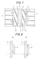
- WO2004/103737 discloses a tread pattern capable of restraining reduction of wet performance, maintaining driving stability and reducing a columnar resonance of a tire, in which a tread 1 is provided with two or more circumferential main grooves 2, 3 extending in a linear or zigzag form in the circumferential direction and a plurality of axial auxiliary grooves 5 formed to at least one circumferential main groove (circumferential main groove 2 in Fig. 7 ), wherein one end of the axial auxiliary grooves 5 is open into the circumferential main groove and the other terminates in the land portion and more than one axial auxiliary groove 5 is always completely included in a ground contact face as shown in Fig. 7 .
- auxiliary grooves branching from the circumferential main groove in this way, the frequency of a columnar resonance can be dispersed.
- the frequency is dispersed, one feels that an easily hearing sound is softened and there becomes silence. This effect is called change to white noise.
- a rib 12 between the circumferential main grooves 2, 3 is divided by the auxiliary groove 5 as shown in Fig. 7 since the auxiliary groove 5 has a certain degree of length.
- the portion of the rib 12 sandwiched between the auxiliary groove 5 and the circumferential main groove 3 extremely reduces its stiffness so that driving stability is deteriorated. Therefore, there is a problem that enough number of auxiliary grooves contributing to sound absorption cannot be provided.
- auxiliary groove it has been found that enough length of the auxiliary groove can be secured and reduction in noise level can be achieved without reduction of stiffness of the rib by making up the auxiliary groove of an axial groove portion open into the circumferential main groove and a circumferential groove portion and by folding this axial groove portion at an acute angle with respect to the circumferential groove portion. That is to say, the circumferential distance of the auxiliary groove 5 folded at an acute angle with respect to the circumferential groove portion as shown in Fig. 8a in comparison to that of the auxiliary groove 5 having the same length of the circumferential groove portion folded at an obtuse angle as shown in Fig. 8b is found to be short.
- an auxiliary groove folded at an acute angle is connected to a circumferential groove is provided so that a columnar resonance can be reduced.
- a circumferential groove provided in a tread central portion easily traps a stone. This is because an axial groove is deformed due to stepping-in and kicking-out deformation to be opened but a circumferential groove is not opened in the absence of such deformation.
- a portion having locally low stiffness for example, the top portion where the tread contact surface contacts the groove wall of the auxiliary groove traps a stone to be deformed and absorbs tire deformation due to stepping-in and kicking-out so that a stone is easily left in the auxiliary groove. It has been found that a stone is easily left especially in the portion where the auxiliary groove is bent at an acute angle.
- a columnar resonance arises from compressed air in the circumferential main groove which is liken to an air column as mentioned above and this columnar resonance symptom is easily generated in the circumferential main groove in the tread central portion.
- the inventors have found it preferable to provide the above-mentioned auxiliary groove branching from the circumferential main groove in the tread central portion, especially in the rib including the tire equator in order to reduce a columnar resonance in the circumferential main groove in the tread central portion.
- the auxiliary groove is provided in a tread side, driving stability may be deteriorated and uneven wear may be generated. Also based on such viewpoint, it is preferable to provide the auxiliary groove in tread central portion.
- the tread When the tread is provided with a plurality of circumferential main grooves, the tread is sectioned into tread sides and a tread central portion.
- the tread central portion as used herein means a region between a circumferential main groove adjacent to one tread edge of the tread and a circumferential main groove adjacent to the other tread edge.
- a center rib described below means a rib including the tire equator.
- an object of the present invention to solve the above-mentioned problems and to provide a pneumatic tire capable of reducing a columnar resonance generated in the circumferential main groove and improving drainage performance without sacrificing excellent driving stability.
- a pneumatic tire capable of reducing a columnar resonance generated in the circumferential main groove and improving drainage performance without sacrificing excellent driving stability by providing the auxiliary groove in the tread central portion in such a manner that the auxiliary groove has at least one end open into the circumferential main groove and is bent at an acute angle.
- a pneumatic tire capable of restraining stone strapping generated by forming the auxiliary groove in the tread central portion by providing the auxiliary groove with a chamfered portion.
- Fig. 1a is a development view of a tread pattern typically showing an embodiment of a pneumatic tire of the present invention
- Fig. 1b is a sectional view taken along line A-A line in Fig. 1a
- Fig. 1c is a partial enlarged view of Fig. 1a
- a tread 1 of a tire is provided with two circumferential main grooves 2, 3, which form a pair across a tire equator C and extend along the tire equator C and a center rib 4 between the circumferential main grooves 2, 3.
- this center rib 4 is provided with auxiliary grooves 5.
- Each of these auxiliary grooves 5 has a circumferential groove portion 5C extending along the tire equator C and an axial groove portion 5W extending from an end of the circumferential groove portion 5C towards the circumferential main groove 2, which is formed adjacent to the tire equator C among two circumferential main grooves 2, 3 and open into this circumferential main groove 2.
- the tread is preferably provided with a lot of grooves having a certain degree of length.
- the present invention has the advantage of keeping good driving stability, dispersing the frequency of a columnar resonance generated in the circumferential main groove and improving drainage performance by providing the auxiliary grooves 5 in the tread central portion, especially in the center rib 4.
- the whole auxiliary groove has to contact the ground in order to absorb a reflected sound wave. Also in this point, the whole auxiliary groove should be folded at an acute angle easily to contact the ground. Therefore, particularly a tire having a wide contact width and low oblateness preferably has a folded auxiliary groove.
- Fig. 1a shows an example that the auxiliary groove.5 is open into the circumferential main groove 2
- the auxiliary groove 5 may be open into the circumferential main groove 3.
- the auxiliary grooves 5 are preferably provided to as many circumferential main grooves as possible.
- the circumferential groove portion 5C of the auxiliary groove 5 has a tapered chamfered portion 5M inclined with respect to the surface of the tread 1 on its groove wall.
- Fig. 1b shows an example that the chamfered portion 5M is provided on the groove wall in the side of the tire equator C
- the chamfered portion 5M provided on the groove wall in the opposite side of the tire equator C can exert the similar effect.
- the inclination angle ⁇ is an angle formed by a line segment which is parallel to the tire axis and passing through an opening edge P of the circumferential groove portion 5C of the auxiliary groove 5 and the chamfered portion 5M of the circumferential groove portion 5C.
- the chamfered portion 5M in the circumferential groove portion 5C it is possible to cut off a portion of locally low stiffness and to improve stone strapping resistance.
- the volume of the auxiliary groove is increased due to the increase of the section area of the auxiliary groove 5 and the frequency dispersion effect is enhanced, which results in reduction of a columnar resonance as well as improvement of drainage performance.
- driving stability may be deteriorated since the ground contact area of the tread is decreased.
- a part of low stiffness is cut off and the area cut off is small, it is thought to have a negligible influence on driving stability.
- the effect of the present invention can be achieved by providing this chamfered portion in the auxiliary groove which is bent at an acute angle and terminates in the land portion.
- the effect of the present invention can be also achieved by providing the chamfered portion in the circumferential groove portion of the auxiliary groove which is bent more than three times although not shown.
- the axial direction as used herein means substantially perpendicular to the circumferential main groove and has a range of 30 degrees to 90 degrees with respect to the circumferential main groove.
- the circumferential direction has a range of 0 degree to 20 degrees with respect to the circumferential main groove.
- the circumferential groove portion does not have to have the angle of the above-mentioned range across its entire length with respect to the circumferential main groove and may be curved a little as described below. It is important to form an acute angle by the circumferential groove portion and the axial groove portion which respectively have an angle of the above-mentioned range.
- the inclination angle ⁇ is preferably within a range of 20 degrees to 60 degrees. When the angle is less than 20 degrees, a stone trapping improvement effect is small. On the other hand, when the angle is more than 60 degrees, the land portion is greatly cut off to reduce stiffness of the rib so that driving stability is degraded.
- the length LC of the circumferential groove portion 5C measured along its longitudinal direction is longer than the length LW of the axial groove portion 5W measured along its longitudinal direction.
- the reason is as follows. In order to achieve dispersion of a columnar resonance sufficiently, the entire length of the auxiliary groove should have a certain degree of length. However, since the rib having the auxiliary groove is thin, the circumferential groove portion 5C has to be lengthened. In Fig.
- the length LC of the circumferential groove portion 5C measured along its longitudinal direction is a length of a line segment passing through the center of the groove width W of the circumferential groove portion 5C, in which the chamfered portion is not included and the length LW of the axial groove portion 5W measured along its longitudinal direction is a length of a line segment passing through the center of the axial groove portion 5W.
- the entire length (LC+LW) of the auxiliary groove 5 obtained by adding the length LC of the circumferential groove portion 5C measured in its longitudinal direction and the length LW of the axial groove portion 5W measured in its longitudinal direction is preferably within a range of 40% to 60% of a ground contact length of the tread. This is because the inventors have studied to know that the frequency of a columnar resonance is well dispersed when the entire length of the auxiliary groove 5 is about half of the ground contact length of the tread.
- the tread is easily deformed in the tire axial direction more than in the tire circumferential direction.
- the depth of the circumferential groove portion 5C is preferably smaller than that of the axial groove portion 5W. With this, it is possible to increase stiffness of the land portion around the auxiliary groove and to obtain driving stability.
- the depth of the axial groove portion 5W at a region adjacent to an opening into the circumferential main groove 2 is smaller than that of the axial groove portion 5W at a region other than the adjacent region.
- the section area of the adjacent region of the axial groove portion 5W to the opening into the circumferential main groove 2 smaller than that of the section area of the axial groove portion 5W at the region other than the adjacent region, it is possible to further improve an interference effect of the axial groove portion 5W and to promote the change from a columnar resonance of the circumferential main groove 2 to white noise.
- the land portion divided by this adjacent region increases its stiffness in comparison to the land portion divided by the axial groove portion 5W at the region other than the adjacent region so as to enhance distortion resistance and driving stability.
- Fig. 2a shows a development view of an asymmetric tread pattern of an example tire of the present invention
- Fig. 2b shows a sectional view taken along line B-B in Fig. 2a
- the example tire shown in Fig. 2a has a similar basic configuration to the tread pattern described with reference to Fig. 1a . That is to say, a tread is provided with two circumferential main grooves 2, 3, which form a pair across a tire equator C and extend along the tire equator C and a center rib 4 between the circumferential main grooves 2, 3.
- this center rib 4 is provided with an auxiliary groove 5 consisting of a circumferential groove portion 5C and an axial groove portion 5W in such a manner that the axial groove portion 5W is bent at an acute angle and terminates in the center rib 4.
- the circumferential groove portion 5C has a tapered chamfered portion 5M inclined with respect to the surface of the tread on its groove wall in the side of the tire equator C.
- the inclination angle ⁇ is 45 degrees.
- the circumferential groove portion 5C of the example tire has the following dimensions; the groove width (the chamfered portion 5M is not included) is 1.5 mm, the groove depth is 4.6 mm, the width of the chamfered portion 5M is 1.6 mm, the depth of the chamfered portion 5M is 1.6 mm and the radius of curvature of the groove bottom is 0.7 mm.
- Conventional Example tires A to C and Example tires A to H have a tire size of 215/60R16.
- Figs. 3a to 3c respectively show a tread pattern of Conventional Example tires A to C.
- Conventional Example tire A is provided not with the auxiliary groove 5 in the center rib 4 of the example tire shown in Fig. 2a but with an auxiliary groove 7 open into the circumferential main groove 6 in a tread side as shown in Fig. 3a .
- Conventional Example tire B is provided not with the circumferential main groove 3 and the auxiliary groove 5 in the center rib 4 of the example tire shown in Fig. 2a but with an auxiliary groove 9 in the center rib 4, which is open into the circumferential main groove 6 and bent at an obtuse angle as shown in Fig. 3b .
- Conventional Example tire C is not provided with the auxiliary groove 5 in the center rib 4 of the example tire shown in Fig. 2a and any other additional auxiliary grooves.
- Figs. 4a to 4d respectively show a tread pattern of Example tires A to D
- Fig. 5a shows a tread pattern of Example tire E
- Fig. 6a shows a tread pattern of Example tire F.
- Example tire A is provided with an auxiliary groove 8 open into the circumferential main groove 3 in the center rib 4 as shown in Fig. 4a instead of the auxiliary groove 5 of the example tire shown in Fig. 2a .
- Example tire B is provided with the auxiliary groove 5 in the center rib 4 of the tread similarly to that of the example tire shown in Fig. 2a but the circumferential groove portion of auxiliary groove 5 does not have a chamfered portion.
- Example tire C which is the same as the example tire shown in Fig. 2a is shown in Fig. 4c for reference.
- Example tire C has a chamfered portion of the auxiliary groove in such a manner that the groove wall of the circumferential groove portion of the auxiliary groove 5 of Example tire B is cut down. All of the auxiliary grooves of Example tires A to C are extended in a linear manner.
- Example tire D is provided not with the auxiliary groove 5 in the center rib 4 of the example tire shown in Fig. 2a but with an auxiliary groove 10 open into the circumferential main groove 3 as shown in Fig. 4d .
- the auxiliary groove 10 has a circumferential portion open into the circumferential main groove 3 and an axial portion bent at an acute angle from the circumferential portion. The bending angle is larger than that of the other Example tires.
- the circumferential main groove 3 is thinner than that of the other Example tires.
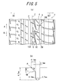
- Fig. 5a shows a development view of an asymmetric tread pattern of Example tire E and Fig. 5b shows a sectional view taken along line C-C in Fig. 5a .
- Example tire E shown in Fig. 5a is provided with two circumferential main grooves 2, 3, which form a pair across a tire equator C and extend along the tire equator C and a center rib 4 between the circumferential main grooves 2, 3.
- this center rib 4 is provided with auxiliary grooves 5 consisting of a circumferential groove portion 5C and an axial groove portion 5W open into the circumferential main groove 3.
- the auxiliary groove 5 is folded at an acute angle and terminates in the center rib 4.
- the circumferential main groove 2 is connected to the circumferential groove portion 5C through a sipe 15A and the circumferential main groove 3 is connected to the axial groove portion 5W through a sipe 15B.
- the circumferential groove portion 5C has a tapered chamfered portion 5M inclined with respect to the surface of the tread on its groove wall in the opposite side of the tire equator C.
- the inclination angle ⁇ is 31 degrees.
- the circumferential groove portion 5C of Example tire E has the following dimensions; the groove width (the chamfered portion 5M is not included) is 4.7 mm, the groove depth is 4.7 mm, the width of the chamfered portion 5M is 6.1 mm, the depth of the chamfered portion 5M is 3.6 mm and the radius of curvature of the groove bottom is 0.7 mm. Since a place where stone trapping is easily generated varies depending on the combination of a groove width, a groove depth and curvature of the circumferential groove portion 5C, a location where the chamfered portion 5M is provided in the circumferential groove portion 5C may be determined according to this place where stone trapping is easily generated.
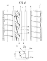
- Fig. 6a shows a development view of an asymmetric tread pattern of Example tire F and Fig. 6b shows a sectional view taken along line D-D in Fig. 6a .
- Example tire F shown in Fig. 6a is provided with a rib 12 between two circumferential main grooves 2, 11, which form a pair across a tire equator C and extend along the tire equator C and an auxiliary groove 5 consisting of a circumferential groove portion 5C and two axial groove portions 5W 1 , 5W 2 in the rib 12.
- the auxiliary groove 5 is folded at an acute angle and terminates in the rib 12.
- the circumferential main groove 2 is connected to the axial groove portion 5W 1 , the axial groove portion 5W 1 is connected to the circumferential groove portion 5C and the circumferential groove portion 5C is bent and folded at an acute angle to be connected to the axial groove portion 5W 2 .
- the circumferential groove portion 5C has a tapered chamfered portion 5M inclined with respect to the surface of the tread on its groove wall in the side of the tire equator C.
- the inclination angle ⁇ is 28 degrees.
- the circumferential groove portion 5C of Example tire F has the following dimensions; the groove width (the chamfered portion 5M is not included) is 2.4 mm, the groove depth is 6.1 mm, the width of the chamfered portion 5M is 3.8 mm, the depth of the chamfered portion 5M is 2.0 mm and the radius of curvature of the groove bottom is 0.7 mm.
- Example tire G which is the same as Example tire E except that the chamfered portion is not provided and Example tire H which is the same as Example tire F except that the chamfered portion is not provided are produced.
- Each of Conventional Example tires A to C and Example tires A to H is mounted on a rim having oblateness of 55 and 16x7J and then the tire/rim assembly is attached to 4 wheels of a passenger car as front and rear wheels.
- the tire internal pressure of 220 kPa is applied to the front and rear wheels.
- the load corresponding to two passengers is applied.
- Each of Conventional Example tires A to C and Example tires A to H is evaluated with regard to driving stability, drainage performance, change of a columnar resonance to white noise and stone strapping resistance.
- a vehicle having the above-mentioned condition is driven on a test course having a circling road including a long straight stretch and a handling evaluation road with many gentle curves at from a low speed to a speed of about 150 km/h and driving stability (handle responsiveness) is evaluated on the basis of the driver's feelings, with 10 points being full score.
- Driving stability is indexed with the value of Example tire A being defined as 0 and the results are shown in Table 2.
- the result of only Conventional Example tire C is +1, which may be because there is no auxiliary groove in the center rib 4.
- Other Conventional Example tires and Example tires A to D show the same results.
- driving stability the results of all of Example tires show that good driving stability is maintained.
- a vehicle having the above-mentioned condition is driven while accelerating on a straight road in water that is 10 mm depth and a speed when hydroplaning is generated is measured.
- the hydroplaning speed is defined in the following method.
- the running distance is measured with using a fifth wheel and the measurement results are plotted with revolutions per minute.
- the speed corresponding to the revolutions per minute when an inclination is suddenly changed is defined as speed of hydroplaning generation.
- the speed of hydroplaning generation is measured three times and the average value is defined as average generation speed.
- This average generation speed is indexed with the value of Example tire A being defined as 100 and drainage performance is evaluated.
- the results are shown in Table 2.
- Conventional Example tires B and C not having an auxiliary groove bent at an acute angle in the center rib 4 show bad results.
- Example tire D does not show its results in Table 2, it shows better results than those of Conventional Example tire C.
- As for drainage performance all of Example tires show the results of not less than index of 99, which are equal or better than
- a vehicle having the above-mentioned condition is driven in stone trapping mode and subsequent stone releasing mode and then the number of stones left in Conventional Example tires A to C and Example tires A to H are measured.
- Conditions of running in stone trapping mode and running in stone releasing mode are shown in Table 1 and their results are shown in Tables 2 and 3.
- the weather is fine and the temperature is 12 degrees C.
- Example tire C having a chamfered portion shows improved results in stone strapping resistance in comparison to those of Conventional Example tires A to C and the other Example tires.
- Example tires E, F having a chamfered portion show improved results in medium and large stone strapping resistance in comparison to those of Example tires G, H.
- improvement in stone trapping resistance is seen in a tire having other oblateness size, the effect of the present invention is remarkable especially in Comparative Example tire G, H, which does not have a chamfered portion and has oblateness of not more than 55 since a lot of stones are trapped.
- the present invention can provide a pneumatic tire capable of keeping driving stability well, changing a columnar resonance generated in the circumferential main groove to white noise to reduce the columnar resonance and improving drainage performance and stone strapping resistance.
Abstract
Description
- The present invention relates to a pneumatic tire reducing a columnar resonance due to a circumferential main groove formed in a tread pattern of the tire.
- As the ratio of tire noise occupied in automobile noise becomes relatively large accompanied with further improvement of the silence in recent vehicles, the reduction of such a tire noise is a significant matter. Particularly, the tire noise at about 1000 Hz easily hearing with the human ears becomes a main factor of the off-vehicle noise and the prompt counter-measures with respect to this noise are also demanded.from a viewpoint of the environmental problems.
- It is generally known that tire noise at a frequency range of approximately 800 to 1400 Hz is generated by a so-called columnar resonance, which is resulted from resonance in an air column defined between a circumferential groove formed in the tread and a road surface in the ground contact face of the tire.
In a state that a tire having a circumferential main groove contacts a ground, a tube having the same length as the ground contact length is formed between a groove wall of the circumferential main groove and the ground contact face. As a result that compression and release of air in this pipe are repeated with running of the tire, noise called a columnar resonance is generated. A frequency f0 of this columnar resonance is a constant frequency represented by
where a sonic speed is v and a length of the tube, that is, a length of a circumferential groove is L. - In order to suppress such a columnar resonance,
WO2004/103737 discloses a tread pattern capable of restraining reduction of wet performance, maintaining driving stability and reducing a columnar resonance of a tire, in which atread 1 is provided with two or more circumferentialmain grooves auxiliary grooves 5 formed to at least one circumferential main groove (circumferentialmain groove 2 inFig. 7 ), wherein one end of the axialauxiliary grooves 5 is open into the circumferential main groove and the other terminates in the land portion and more than one axialauxiliary groove 5 is always completely included in a ground contact face as shown inFig. 7 . - By providing the auxiliary grooves branching from the circumferential main groove in this way, the frequency of a columnar resonance can be dispersed. When the frequency is dispersed, one feels that an easily hearing sound is softened and there becomes silence. This effect is called change to white noise.
The dispersion effect of a frequency depends on a shape of the auxiliary groove. Specifically a frequency f of sound dispersed and newly generated is represented by
- n: oscillation degree (n=1,3,5...)
- In a pneumatic tire described in
WO2004/103737 the axial auxiliary groove continued into the circumferential main groove can disperse the frequency of a columnar resonance generated in the circumferential main groove and change it to white noise. However, there is still the following problem in order to enhance the effect of this technique.
In a pneumatic tire described inWO2004/103737 arib 12 between the circumferentialmain grooves auxiliary groove 5 as shown inFig. 7 since theauxiliary groove 5 has a certain degree of length. With this, the portion of therib 12 sandwiched between theauxiliary groove 5 and the circumferentialmain groove 3 extremely reduces its stiffness so that driving stability is deteriorated. Therefore, there is a problem that enough number of auxiliary grooves contributing to sound absorption cannot be provided. - It has been found that enough length of the auxiliary groove can be secured and reduction in noise level can be achieved without reduction of stiffness of the rib by making up the auxiliary groove of an axial groove portion open into the circumferential main groove and a circumferential groove portion and by folding this axial groove portion at an acute angle with respect to the circumferential groove portion.
That is to say, the circumferential distance of theauxiliary groove 5 folded at an acute angle with respect to the circumferential groove portion as shown inFig. 8a in comparison to that of theauxiliary groove 5 having the same length of the circumferential groove portion folded at an obtuse angle as shown inFig. 8b is found to be short. Therefore, even in a tire having a small tire size (outer diameter), an auxiliary groove folded at an acute angle is connected to a circumferential groove is provided so that a columnar resonance can be reduced.
In addition, it has been found that a circumferential groove provided in a tread central portion easily traps a stone. This is because an axial groove is deformed due to stepping-in and kicking-out deformation to be opened but a circumferential groove is not opened in the absence of such deformation. When an auxiliary groove is provided in a tread central portion, especially the land portions sandwiching a circumferential groove portion reduce their stiffness, which causes a problem that stone trapping is easily generated in the grooves.
In other words, a portion having locally low stiffness, for example, the top portion where the tread contact surface contacts the groove wall of the auxiliary groove traps a stone to be deformed and absorbs tire deformation due to stepping-in and kicking-out so that a stone is easily left in the auxiliary groove. It has been found that a stone is easily left especially in the portion where the auxiliary groove is bent at an acute angle. - A columnar resonance arises from compressed air in the circumferential main groove which is liken to an air column as mentioned above and this columnar resonance symptom is easily generated in the circumferential main groove in the tread central portion. The inventors have found it preferable to provide the above-mentioned auxiliary groove branching from the circumferential main groove in the tread central portion, especially in the rib including the tire equator in order to reduce a columnar resonance in the circumferential main groove in the tread central portion. In addition, in case that the auxiliary groove is provided in a tread side, driving stability may be deteriorated and uneven wear may be generated. Also based on such viewpoint, it is preferable to provide the auxiliary groove in tread central portion.
- When the tread is provided with a plurality of circumferential main grooves, the tread is sectioned into tread sides and a tread central portion. The tread central portion as used herein means a region between a circumferential main groove adjacent to one tread edge of the tread and a circumferential main groove adjacent to the other tread edge. In addition, a center rib described below means a rib including the tire equator.
- It is, therefore, an object of the present invention to solve the above-mentioned problems and to provide a pneumatic tire capable of reducing a columnar resonance generated in the circumferential main groove and improving drainage performance without sacrificing excellent driving stability.
In addition, it is another object of the present invention to provide a pneumatic tire improving stone trapping resistance. - The subject matter of the present invention is as follows.
- (1) A pneumatic tire comprising a tread provided with at least two circumferential main grooves and a rib defined in a tread central portion by the circumferential main grooves, wherein
an auxiliary groove is formed in the tread central portion, the auxiliary groove having a circumferential groove portion extending in a tire equator direction and an axial groove portion extending from an end of the circumferential groove portion in such a manner that the axial groove portion is bent at an acute angle to the circumferential groove portion, and
at least an end of the auxiliary groove is open into the circumferential main groove. - (2) The pneumatic tire according to the above (1), wherein the circumferential main grooves form a pair across the tire equator.
- (3) The pneumatic tire according to the above (1) or (2), wherein the circumferential groove portion of the auxiliary groove has a chamfered portion inclined with respect to a surface of the tread on at least one groove wall of both groove walls sectioning the circumferential groove portion.
- (4) The pneumatic tire according to the above (3), wherein the chamfered portion is formed on one groove wall of the circumferential groove portion in a side of the axial groove portion.
- (5) The pneumatic tire according to the above (3) or (4), wherein the chamfered portion formed on one groove wall of the circumferential groove portion of the auxiliary groove has an inclination angle within a range between 20 degrees and 60 degrees with respect to the surface of the tread.
- (6) The pneumatic tire according to any one of the above (3) to (5), wherein the chamfered portion is formed on one groove wall of the circumferential groove portion in a side of the axial groove portion and has a depth of 10% to 60% of that of the circumferential groove portion.
- (7) The pneumatic tire according to any one of the above (1) to (6), wherein
a length of the circumferential groove portion of the auxiliary groove measured along its longitudinal direction is longer than that of the axial groove portion of the auxiliary groove measured along its longitudinal direction and
an entire length of the auxiliary groove obtained by adding the length of the circumferential groove portion and the length of the axial groove portion is within a range of 40% to 60% of a ground contact length of the tread. - (8) The pneumatic tire according to any one of the above (1) to (7), wherein a depth of the circumferential groove portion of the auxiliary groove is smaller than that of the axial groove portion of the auxiliary groove.
- (9) The pneumatic tire according to any one of the above (1) to (8), wherein a depth of the axial groove portion of the auxiliary groove at a region adjacent to an opening into the circumferential main groove is smaller than that of the axial groove portion at a region other than the adjacent region.
- According to the present invention, it is possible to provide a pneumatic tire capable of reducing a columnar resonance generated in the circumferential main groove and improving drainage performance without sacrificing excellent driving stability by providing the auxiliary groove in the tread central portion in such a manner that the auxiliary groove has at least one end open into the circumferential main groove and is bent at an acute angle. In addition, it is possible to provide a pneumatic tire capable of restraining stone strapping generated by forming the auxiliary groove in the tread central portion by providing the auxiliary groove with a chamfered portion.
-
- [
Fig. 1] Fig. 1a is a development view of a tread pattern typically showing an embodiment of a pneumatic tire of the present invention,Fig. 1b is a sectional view taken along line A-A inFig. 1a and Fig. 1c is a partial enlarged view ofFig. 1a . - [
Fig. 2] Fig. 2a shows a development view of a tread pattern of an example tire of the present invention andFig. 2b shows a sectional view taken along line B-B inFig. 2a . - [
Fig. 3] Figs. 3a to 3c respectively show a tread pattern of Conventional Example tires A to C. - [
Fig. 4] Figs. 4a to 4c respectively show a tread pattern of Example tires A to D. - [
Fig. 5] Fig. 5a shows a development view of a tread pattern of Example tire E of the present invention andFig. 5b shows a sectional view taken along line C-C inFig. 5a . - [
Fig. 6] Fig. 6a shows a development view of a tread pattern of Example tire F of the present invention andFig. 6b shows a sectional view taken along line D-D inFig. 6a . - [
Fig. 7] Fig. 7 shows a development view of a tread pattern of a conventional pneumatic tire. - [
Fig. 8] Fig. 8a shows an example in which an auxiliary groove is bent at an acute angle andFig. 8b shows an example in which an auxiliary groove is bent at an obtuse angle. -
- 1
- tread
- 2,3,6
- circumferential main groove
- 4
- center rib
- 5,7,8,9,10
- auxiliary groove
- 12
- rib
- 15A,15B
- sipe
- 5C
- circumferential groove portion
- 5W,5W1,5W2
- axial groove portion
- 5M
- chamfered portion
- C
- tire equator
- P
- opening edge
- Hereinafter, embodiments of a pneumatic tire according to the present invention will be described in detail with reference to the drawings.
In addition, internal reinforcement structures and the like of this tire is not described since they are similar to those of a general radial tire. -
Fig. 1a is a development view of a tread pattern typically showing an embodiment of a pneumatic tire of the present invention,Fig. 1b is a sectional view taken along line A-A line inFig. 1a and Fig. 1c is a partial enlarged view ofFig. 1a .
As shown inFig. 1a , atread 1 of a tire is provided with two circumferentialmain grooves center rib 4 between the circumferentialmain grooves center rib 4 is provided withauxiliary grooves 5. Each of theseauxiliary grooves 5 has acircumferential groove portion 5C extending along the tire equator C and anaxial groove portion 5W extending from an end of thecircumferential groove portion 5C towards the circumferentialmain groove 2, which is formed adjacent to the tire equator C among two circumferentialmain grooves main groove 2.
By communicating theauxiliary groove 5 with the circumferentialmain groove 2 in this way, the frequency of a columnar resonance generated in the circumferential main groove can be dispersed as stated above.
In view of drainage performance in addition to sound absorption effect, the tread is preferably provided with a lot of grooves having a certain degree of length. Thus, by forming the auxiliary groove to be bent at an acute angle, it is possible to form a lot of grooves while assuring stiffness of the rib without dividing the rib.
It is preferable to provide grooves particularly in thecenter rib 4, wherein ground contact pressure is high so that drainage performance and calm characteristics can be improved by providing the above-mentionedauxiliary groove 5.
As stated above, the present invention has the advantage of keeping good driving stability, dispersing the frequency of a columnar resonance generated in the circumferential main groove and improving drainage performance by providing theauxiliary grooves 5 in the tread central portion, especially in thecenter rib 4. - From a viewpoint of the auxiliary groove itself, the whole auxiliary groove has to contact the ground in order to absorb a reflected sound wave. Also in this point, the whole auxiliary groove should be folded at an acute angle easily to contact the ground. Therefore, particularly a tire having a wide contact width and low oblateness preferably has a folded auxiliary groove.
- Although
Fig. 1a shows an example that the auxiliary groove.5 is open into the circumferentialmain groove 2, theauxiliary groove 5 may be open into the circumferentialmain groove 3. From a viewpoint of dispersion effect of a columnar resonance, theauxiliary grooves 5 are preferably provided to as many circumferential main grooves as possible. - It is important that, as shown in
Fig. 1b , thecircumferential groove portion 5C of theauxiliary groove 5 has a tapered chamferedportion 5M inclined with respect to the surface of thetread 1 on its groove wall. AlthoughFig. 1b shows an example that the chamferedportion 5M is provided on the groove wall in the side of the tire equator C, the chamferedportion 5M provided on the groove wall in the opposite side of the tire equator C can exert the similar effect. In particular, it is preferable to provide the chamfered portion on the groove wall in the side wall of tire equator C because the ground contact pressure is high in the tire equator C and stone trapping is easily generated.
The inclination angle θ is an angle formed by a line segment which is parallel to the tire axis and passing through an opening edge P of thecircumferential groove portion 5C of theauxiliary groove 5 and the chamferedportion 5M of thecircumferential groove portion 5C.
When theauxiliary groove 5 is provided in thecenter rib 4 of thetread 1 of the tire, particularly the land portions on the both sides of thecircumferential groove portion 5C reduce their stiffness so that thecircumferential groove portion 5C traps a stone. A portion having locally low stiffness, for example, the top portion where the tread contact surface contacts the groove wall traps a stone to be deformed and absorbs tire deformation due to stepping-in and kicking-out so that a stone is easily left in the groove. Therefore, by providing the chamferedportion 5M in thecircumferential groove portion 5C, it is possible to cut off a portion of locally low stiffness and to improve stone strapping resistance.
In addition, by providing the chamferedportion 5M in thecircumferential groove portion 5C, the volume of the auxiliary groove is increased due to the increase of the section area of theauxiliary groove 5 and the frequency dispersion effect is enhanced, which results in reduction of a columnar resonance as well as improvement of drainage performance. By providing the chamferedportion 5M in thecircumferential groove portion 5C, driving stability may be deteriorated since the ground contact area of the tread is decreased. However, since a part of low stiffness is cut off and the area cut off is small, it is thought to have a negligible influence on driving stability. - The effect of the present invention can be achieved by providing this chamfered portion in the auxiliary groove which is bent at an acute angle and terminates in the land portion. The effect of the present invention can be also achieved by providing the chamfered portion in the circumferential groove portion of the auxiliary groove which is bent more than three times although not shown.
The axial direction as used herein means substantially perpendicular to the circumferential main groove and has a range of 30 degrees to 90 degrees with respect to the circumferential main groove. In addition, the circumferential direction has a range of 0 degree to 20 degrees with respect to the circumferential main groove. The circumferential groove portion does not have to have the angle of the above-mentioned range across its entire length with respect to the circumferential main groove and may be curved a little as described below. It is important to form an acute angle by the circumferential groove portion and the axial groove portion which respectively have an angle of the above-mentioned range. - In addition, the inclination angle θ is preferably within a range of 20 degrees to 60 degrees. When the angle is less than 20 degrees, a stone trapping improvement effect is small. On the other hand, when the angle is more than 60 degrees, the land portion is greatly cut off to reduce stiffness of the rib so that driving stability is degraded.
- As shown in
Fig. 1c , the length LC of thecircumferential groove portion 5C measured along its longitudinal direction is longer than the length LW of theaxial groove portion 5W measured along its longitudinal direction. The reason is as follows. In order to achieve dispersion of a columnar resonance sufficiently, the entire length of the auxiliary groove should have a certain degree of length. However, since the rib having the auxiliary groove is thin, thecircumferential groove portion 5C has to be lengthened.
InFig. 1c the length LC of thecircumferential groove portion 5C measured along its longitudinal direction is a length of a line segment passing through the center of the groove width W of thecircumferential groove portion 5C, in which the chamfered portion is not included and the length LW of theaxial groove portion 5W measured along its longitudinal direction is a length of a line segment passing through the center of theaxial groove portion 5W. - In addition, the entire length (LC+LW) of the
auxiliary groove 5 obtained by adding the length LC of thecircumferential groove portion 5C measured in its longitudinal direction and the length LW of theaxial groove portion 5W measured in its longitudinal direction is preferably within a range of 40% to 60% of a ground contact length of the tread.
This is because the inventors have studied to know that the frequency of a columnar resonance is well dispersed when the entire length of theauxiliary groove 5 is about half of the ground contact length of the tread. - Next, a configuration further to improve stiffness of the
tread 1 will be explained.
The tread is easily deformed in the tire axial direction more than in the tire circumferential direction. In addition, when a groove is formed in the tread, the deeper the groove is, the lower stiffness of the tread is. Therefore, the depth of thecircumferential groove portion 5C is preferably smaller than that of theaxial groove portion 5W. With this, it is possible to increase stiffness of the land portion around the auxiliary groove and to obtain driving stability. - It is preferable for the
axial groove portion 5W of theauxiliary groove 5 that the depth of theaxial groove portion 5W at a region adjacent to an opening into the circumferentialmain groove 2 is smaller than that of theaxial groove portion 5W at a region other than the adjacent region.
In other words, by setting the section area of the adjacent region of theaxial groove portion 5W to the opening into the circumferentialmain groove 2 smaller than that of the section area of theaxial groove portion 5W at the region other than the adjacent region, it is possible to further improve an interference effect of theaxial groove portion 5W and to promote the change from a columnar resonance of the circumferentialmain groove 2 to white noise.
In addition, by setting the depth of the adjacent region of theaxial groove portion 5W to the opening into the circumferentialmain groove 2 smaller, the land portion divided by this adjacent region increases its stiffness in comparison to the land portion divided by theaxial groove portion 5W at the region other than the adjacent region so as to enhance distortion resistance and driving stability. - Next, tires according to the present invention are experimentally produced and evaluated for their performance. The results will be explained below.
Fig. 2a shows a development view of an asymmetric tread pattern of an example tire of the present invention andFig. 2b shows a sectional view taken along line B-B inFig. 2a .
The example tire shown inFig. 2a has a similar basic configuration to the tread pattern described with reference toFig. 1a . That is to say, a tread is provided with two circumferentialmain grooves center rib 4 between the circumferentialmain grooves center rib 4 is provided with anauxiliary groove 5 consisting of acircumferential groove portion 5C and anaxial groove portion 5W in such a manner that theaxial groove portion 5W is bent at an acute angle and terminates in thecenter rib 4. - As shown in
Fig. 2b , thecircumferential groove portion 5C has a tapered chamferedportion 5M inclined with respect to the surface of the tread on its groove wall in the side of the tire equator C. The inclination angle θ is 45 degrees.
Thecircumferential groove portion 5C of the example tire has the following dimensions; the groove width (the chamferedportion 5M is not included) is 1.5 mm, the groove depth is 4.6 mm, the width of the chamferedportion 5M is 1.6 mm, the depth of the chamferedportion 5M is 1.6 mm and the radius of curvature of the groove bottom is 0.7 mm. - Conventional Example tires A to C and Example tires A to H have a tire size of 215/60R16.
Figs. 3a to 3c respectively show a tread pattern of Conventional Example tires A to C.
Conventional Example tire A is provided not with theauxiliary groove 5 in thecenter rib 4 of the example tire shown inFig. 2a but with anauxiliary groove 7 open into the circumferentialmain groove 6 in a tread side as shown inFig. 3a .
Conventional Example tire B is provided not with the circumferentialmain groove 3 and theauxiliary groove 5 in thecenter rib 4 of the example tire shown inFig. 2a but with anauxiliary groove 9 in thecenter rib 4, which is open into the circumferentialmain groove 6 and bent at an obtuse angle as shown inFig. 3b .
Conventional Example tire C is not provided with theauxiliary groove 5 in thecenter rib 4 of the example tire shown inFig. 2a and any other additional auxiliary grooves. -
Figs. 4a to 4d respectively show a tread pattern of Example tires A to D,Fig. 5a shows a tread pattern of Example tire E andFig. 6a shows a tread pattern of Example tire F.
Example tire A is provided with an auxiliary groove 8 open into the circumferentialmain groove 3 in thecenter rib 4 as shown inFig. 4a instead of theauxiliary groove 5 of the example tire shown inFig. 2a .
Example tire B is provided with theauxiliary groove 5 in thecenter rib 4 of the tread similarly to that of the example tire shown inFig. 2a but the circumferential groove portion ofauxiliary groove 5 does not have a chamfered portion.
Example tire C which is the same as the example tire shown inFig. 2a is shown inFig. 4c for reference. Example tire C has a chamfered portion of the auxiliary groove in such a manner that the groove wall of the circumferential groove portion of theauxiliary groove 5 of Example tire B is cut down.
All of the auxiliary grooves of Example tires A to C are extended in a linear manner.
Example tire D is provided not with theauxiliary groove 5 in thecenter rib 4 of the example tire shown inFig. 2a but with anauxiliary groove 10 open into the circumferentialmain groove 3 as shown inFig. 4d . Theauxiliary groove 10 has a circumferential portion open into the circumferentialmain groove 3 and an axial portion bent at an acute angle from the circumferential portion. The bending angle is larger than that of the other Example tires. In addition, the circumferentialmain groove 3 is thinner than that of the other Example tires. -
Fig. 5a shows a development view of an asymmetric tread pattern of Example tire E andFig. 5b shows a sectional view taken along line C-C inFig. 5a .
Example tire E shown inFig. 5a is provided with two circumferentialmain grooves center rib 4 between the circumferentialmain grooves center rib 4 is provided withauxiliary grooves 5 consisting of acircumferential groove portion 5C and anaxial groove portion 5W open into the circumferentialmain groove 3. Theauxiliary groove 5 is folded at an acute angle and terminates in thecenter rib 4. The circumferentialmain groove 2 is connected to thecircumferential groove portion 5C through asipe 15A and the circumferentialmain groove 3 is connected to theaxial groove portion 5W through asipe 15B.
As shown inFig. 5b thecircumferential groove portion 5C has a tapered chamferedportion 5M inclined with respect to the surface of the tread on its groove wall in the opposite side of the tire equator C. The inclination angle θ is 31 degrees. Thecircumferential groove portion 5C of Example tire E has the following dimensions; the groove width (the chamferedportion 5M is not included) is 4.7 mm, the groove depth is 4.7 mm, the width of the chamferedportion 5M is 6.1 mm, the depth of the chamferedportion 5M is 3.6 mm and the radius of curvature of the groove bottom is 0.7 mm.
Since a place where stone trapping is easily generated varies depending on the combination of a groove width, a groove depth and curvature of thecircumferential groove portion 5C, a location where the chamferedportion 5M is provided in thecircumferential groove portion 5C may be determined according to this place where stone trapping is easily generated. -
Fig. 6a shows a development view of an asymmetric tread pattern of Example tire F andFig. 6b shows a sectional view taken along line D-D inFig. 6a .
Example tire F shown inFig. 6a is provided with arib 12 between two circumferentialmain grooves auxiliary groove 5 consisting of acircumferential groove portion 5C and twoaxial groove portions rib 12. Theauxiliary groove 5 is folded at an acute angle and terminates in therib 12. The circumferentialmain groove 2 is connected to theaxial groove portion 5W1, theaxial groove portion 5W1 is connected to thecircumferential groove portion 5C and thecircumferential groove portion 5C is bent and folded at an acute angle to be connected to theaxial groove portion 5W2.
As shown inFig. 6b , thecircumferential groove portion 5C has a tapered chamferedportion 5M inclined with respect to the surface of the tread on its groove wall in the side of the tire equator C. The inclination angle θ is 28 degrees. Thecircumferential groove portion 5C of Example tire F has the following dimensions; the groove width (the chamferedportion 5M is not included) is 2.4 mm, the groove depth is 6.1 mm, the width of the chamferedportion 5M is 3.8 mm, the depth of the chamferedportion 5M is 2.0 mm and the radius of curvature of the groove bottom is 0.7 mm. - In addition, Example tire G which is the same as Example tire E except that the chamfered portion is not provided and Example tire H which is the same as Example tire F except that the chamfered portion is not provided are produced.
- Each of Conventional Example tires A to C and Example tires A to H is mounted on a rim having oblateness of 55 and 16x7J and then the tire/rim assembly is attached to 4 wheels of a passenger car as front and rear wheels. The tire internal pressure of 220 kPa is applied to the front and rear wheels. The load corresponding to two passengers is applied.
Each of Conventional Example tires A to C and Example tires A to H is evaluated with regard to driving stability, drainage performance, change of a columnar resonance to white noise and stone strapping resistance. - A vehicle having the above-mentioned condition is driven on a test course having a circling road including a long straight stretch and a handling evaluation road with many gentle curves at from a low speed to a speed of about 150 km/h and driving stability (handle responsiveness) is evaluated on the basis of the driver's feelings, with 10 points being full score. Driving stability is indexed with the value of Example tire A being defined as 0 and the results are shown in Table 2.
The result of only Conventional Example tire C is +1, which may be because there is no auxiliary groove in thecenter rib 4. Other Conventional Example tires and Example tires A to D show the same results. As for driving stability, the results of all of Example tires show that good driving stability is maintained. - A vehicle having the above-mentioned condition is driven while accelerating on a straight road in water that is 10 mm depth and a speed when hydroplaning is generated is measured. The hydroplaning speed is defined in the following method. The running distance is measured with using a fifth wheel and the measurement results are plotted with revolutions per minute. The speed corresponding to the revolutions per minute when an inclination is suddenly changed is defined as speed of hydroplaning generation. The speed of hydroplaning generation is measured three times and the average value is defined as average generation speed. This average generation speed is indexed with the value of Example tire A being defined as 100 and drainage performance is evaluated. The results are shown in Table 2.
Conventional Example tires B and C not having an auxiliary groove bent at an acute angle in thecenter rib 4 show bad results. Although Example tire D does not show its results in Table 2, it shows better results than those of Conventional Example tire C. As for drainage performance, all of Example tires show the results of not less than index of 99, which are equal or better than those of Conventional Example tires. - Change of a columnar resonance to white noise is evaluated on the basis of the driver's feelings under the same condition as that of the above-mentioned driving stability. When there is a difference of not less than 1 in evaluation results, it means significantly different.
As for the change of a columnar resonance to white noise, the tires having the auxiliary groove open into the circumferential main groove in the tread central portion show good results. Although Example tire D does not show its results in Table 2, it shows better results than those of Conventional Example tire C. All of Example tires show not less than 1.6, which means improved results and significantly different from the results of Conventional Example tires except for Conventional Example tire B. - A vehicle having the above-mentioned condition is driven in stone trapping mode and subsequent stone releasing mode and then the number of stones left in Conventional Example tires A to C and Example tires A to H are measured. Conditions of running in stone trapping mode and running in stone releasing mode are shown in Table 1 and their results are shown in Tables 2 and 3. The weather is fine and the temperature is 12 degrees C.
-
[Table 1] Running in stone trapping mode Running in stone releasing mode Location Durable gravel road Durable circular road Running distance about 1 km about 2 km Speed 20 km/h 20→70→80→20 km/h (constant) (even running) Steering force Nearly zero Slalom corresponding 0.23G -
[Table 2] Reference figure Driving stability Drainage performance Change of a columnar resonance to white noise Number of stone left
(sum of four wheels)small medium large sum Conventional Example tire A Fig. 3a ±0 99 +1.0 2 40 0 42 Conventional Example tire B Fig. 3b ±0 95 +2.0 2 46 5 53 Conventional Example tire C Fig. 3c +1 95 -2.0 2 38 0 40 Example tire A Fig. 4a ±0 100 +1.6 2 49 4 55 Example tire B Fig. 4b ±0 99 +2.0 2 48 4 54 Example tire C Fig. 4c ±0 103 +2.0 2 38 0 40 -
[Table 3] Reference figure Number of stone left(sum of four wheels) small medium large sum Example tire E Fig. 5a 2 35 0 37 Example tire F Fig. 6a 2 38 0 40 Example tire G - 2 48 4 54 Example tire H - 2 50 5 57 - In Tables 2 and 3 "small" means that the diameter of a stone is less than 5 mm, "medium" means that the diameter thereof is not less than 5 mm and less than 10 mm and "large" means that the diameter thereof is not less than 10 mm.
- As for stone strapping resistance, Example tire C having a chamfered portion shows improved results in stone strapping resistance in comparison to those of Conventional Example tires A to C and the other Example tires.
Example tires E, F having a chamfered portion show improved results in medium and large stone strapping resistance in comparison to those of Example tires G, H.
Although improvement in stone trapping resistance is seen in a tire having other oblateness size, the effect of the present invention is remarkable especially in Comparative Example tire G, H, which does not have a chamfered portion and has oblateness of not more than 55 since a lot of stones are trapped. - As stated above, the present invention can provide a pneumatic tire capable of keeping driving stability well, changing a columnar resonance generated in the circumferential main groove to white noise to reduce the columnar resonance and improving drainage performance and stone strapping resistance.
Claims (9)
- A pneumatic tire comprising a tread provided with at least two circumferential main grooves and a rib defined in a tread central portion by the circumferential main grooves, wherein
an auxiliary groove is formed in the tread central portion, the auxiliary groove having a circumferential groove portion extending in a tire equator direction and an axial groove portion extending from an end of the circumferential groove portion in such a manner that the axial groove portion is bent at an acute angle to the circumferential groove portion, and
at least an end of the auxiliary groove is open into the circumferential main groove. - The pneumatic tire according to claim 1, wherein the circumferential main grooves form a pair across the tire equator.
- The pneumatic tire according to claim 1 or 2, wherein the circumferential groove portion of the auxiliary groove has a chamfered portion inclined with respect to a surface of the tread on at least one groove wall of both groove walls sectioning the circumferential groove portion.
- The pneumatic tire according to claim 3, wherein the chamfered portion is formed on one groove wall of the circumferential groove portion in a side of the axial groove portion.
- The pneumatic tire according to claim 3 or 4, wherein the chamfered portion formed on one groove wall of the circumferential groove portion of the auxiliary groove has an inclination angle within a range between 20 degrees and 60 degrees with respect to the surface of the tread.
- The pneumatic tire according to any one of claims 3 to 5, wherein the chamfered portion is formed on one groove wall of the circumferential groove portion in a side of the axial groove portion and has a depth of 10% to 60% of that of the circumferential groove portion.
- The pneumatic tire according to any one of claims 1 to 6, wherein
a length of the circumferential groove portion of the auxiliary groove measured along its longitudinal direction is longer than that of the axial groove portion of the auxiliary groove measured along its longitudinal direction and
an entire length of the auxiliary groove obtained by adding the length of the circumferential groove portion and the length of the axial groove portion is within a range of 40% to 60% of a ground contact length of the tread. - The pneumatic tire according to any one of claims 1 to 7, wherein a depth of the circumferential groove portion of the auxiliary groove is smaller than that of the axial groove portion of the auxiliary groove.
- The pneumatic tire according to any one of claims 1 to 8, wherein a depth of the axial groove portion of the auxiliary groove at a region adjacent to an opening into the circumferential main groove is smaller than that of the axial groove portion at a region other than the adjacent region.
Priority Applications (1)
| Application Number | Priority Date | Filing Date | Title |
|---|---|---|---|
| EP11184140.9A EP2404770B1 (en) | 2007-05-14 | 2008-05-09 | Pneumatic tire |
Applications Claiming Priority (3)
| Application Number | Priority Date | Filing Date | Title |
|---|---|---|---|
| JP2007127895 | 2007-05-14 | ||
| JP2007315116 | 2007-12-05 | ||
| PCT/JP2008/058671 WO2008143034A1 (en) | 2007-05-14 | 2008-05-09 | Pneumatic tire |
Related Child Applications (2)
| Application Number | Title | Priority Date | Filing Date |
|---|---|---|---|
| EP11184140.9A Division EP2404770B1 (en) | 2007-05-14 | 2008-05-09 | Pneumatic tire |
| EP11184140.9 Division-Into | 2011-10-06 |
Publications (3)
| Publication Number | Publication Date |
|---|---|
| EP2154008A1 true EP2154008A1 (en) | 2010-02-17 |
| EP2154008A4 EP2154008A4 (en) | 2011-05-11 |
| EP2154008B1 EP2154008B1 (en) | 2012-11-28 |
Family
ID=40031744
Family Applications (2)
| Application Number | Title | Priority Date | Filing Date |
|---|---|---|---|
| EP11184140.9A Not-in-force EP2404770B1 (en) | 2007-05-14 | 2008-05-09 | Pneumatic tire |
| EP08752554A Not-in-force EP2154008B1 (en) | 2007-05-14 | 2008-05-09 | Pneumatic tire |
Family Applications Before (1)
| Application Number | Title | Priority Date | Filing Date |
|---|---|---|---|
| EP11184140.9A Not-in-force EP2404770B1 (en) | 2007-05-14 | 2008-05-09 | Pneumatic tire |
Country Status (7)
| Country | Link |
|---|---|
| US (1) | US9174497B2 (en) |
| EP (2) | EP2404770B1 (en) |
| JP (1) | JP5231405B2 (en) |
| KR (2) | KR20120001813A (en) |
| CN (2) | CN102423993B (en) |
| ES (1) | ES2398403T3 (en) |
| WO (1) | WO2008143034A1 (en) |
Cited By (6)
| Publication number | Priority date | Publication date | Assignee | Title |
|---|---|---|---|---|
| CN103112320A (en) * | 2013-02-25 | 2013-05-22 | 上海轮胎橡胶(集团)股份有限公司轮胎研究所 | Low-noise tread pattern block |
| EP2537688A3 (en) * | 2011-06-20 | 2014-05-21 | Sumitomo Rubber Industries Limited | Pneumatic tire |
| WO2015197211A1 (en) * | 2014-06-26 | 2015-12-30 | Continental Reifen Deutschland Gmbh | Vehicle tires |
| EP2974887A4 (en) * | 2013-03-13 | 2016-01-20 | Bridgestone Corp | Pneumatic tire |
| EP2641753A4 (en) * | 2010-11-15 | 2016-08-03 | Bridgestone Corp | Pneumatic radial tire for use on passenger vehicle |
| CN112009178A (en) * | 2019-05-31 | 2020-12-01 | 住友橡胶工业株式会社 | Tyre for vehicle wheels |
Families Citing this family (16)
| Publication number | Priority date | Publication date | Assignee | Title |
|---|---|---|---|---|
| JP5086012B2 (en) * | 2007-09-12 | 2012-11-28 | 株式会社ブリヂストン | Pneumatic tire |
| JP4816675B2 (en) | 2008-04-22 | 2011-11-16 | 横浜ゴム株式会社 | Pneumatic tire |
| JP5346663B2 (en) * | 2009-04-16 | 2013-11-20 | 株式会社ブリヂストン | Pneumatic tire |
| JP4709303B2 (en) * | 2009-08-07 | 2011-06-22 | 株式会社ブリヂストン | tire |
| JP5396203B2 (en) * | 2009-09-03 | 2014-01-22 | 株式会社ブリヂストン | tire |
| US8899286B2 (en) * | 2009-12-25 | 2014-12-02 | Compagnie Generale Des Etablissements Michelin | Pneumatic tire tread |
| JP5475476B2 (en) * | 2010-01-07 | 2014-04-16 | 株式会社ブリヂストン | Pneumatic tire |
| EP2974885B1 (en) | 2010-03-29 | 2017-05-17 | Bridgestone Corporation | Tire |
| JP5820442B2 (en) * | 2013-08-23 | 2015-11-24 | 株式会社ブリヂストン | Pneumatic tire |
| JP6591149B2 (en) * | 2014-08-29 | 2019-10-16 | 株式会社ブリヂストン | Pneumatic tire |
| USD768396S1 (en) * | 2014-10-24 | 2016-10-11 | Under Armour, Inc. | Textile with deposited pattern |
| JP6834291B2 (en) * | 2016-09-21 | 2021-02-24 | 住友ゴム工業株式会社 | Pneumatic tires |
| CN111032373B (en) * | 2017-09-06 | 2022-07-12 | 横滨橡胶株式会社 | Pneumatic tire |
| JP6929188B2 (en) * | 2017-10-13 | 2021-09-01 | Toyo Tire株式会社 | Pneumatic tires |
| JP7102893B2 (en) * | 2018-04-17 | 2022-07-20 | 住友ゴム工業株式会社 | tire |
| JP7139288B2 (en) * | 2019-06-11 | 2022-09-20 | 株式会社ブリヂストン | tire |
Citations (4)
| Publication number | Priority date | Publication date | Assignee | Title |
|---|---|---|---|---|
| JPH0776203A (en) * | 1993-06-17 | 1995-03-20 | Sumitomo Rubber Ind Ltd | Pneumatic tire |
| EP1106395A2 (en) * | 1999-12-07 | 2001-06-13 | Sumitomo Rubber Industries Ltd. | Tyre |
| JP2003146018A (en) * | 2001-11-14 | 2003-05-21 | Sumitomo Rubber Ind Ltd | Pneumatic tire |
| JP2005022530A (en) * | 2003-07-02 | 2005-01-27 | Bridgestone Corp | Pneumatic tire |
Family Cites Families (27)
| Publication number | Priority date | Publication date | Assignee | Title |
|---|---|---|---|---|
| JPH02179508A (en) * | 1988-12-29 | 1990-07-12 | Yokohama Rubber Co Ltd:The | Pneumatic tire |
| JPH06191226A (en) * | 1992-12-25 | 1994-07-12 | Bridgestone Corp | Pneumatic tire |
| JPH0971106A (en) * | 1995-09-08 | 1997-03-18 | Bridgestone Corp | Pneumatic radial tire |
| JP3559378B2 (en) * | 1996-02-29 | 2004-09-02 | 株式会社ブリヂストン | Pneumatic tire pair |
| JP3017677B2 (en) * | 1996-06-10 | 2000-03-13 | 住友ゴム工業株式会社 | Winter passenger car tires |
| JPH1137617A (en) | 1997-07-15 | 1999-02-12 | Daikin Ind Ltd | Air conditioner using natural refrigerant |
| US6123130A (en) * | 1997-11-11 | 2000-09-26 | Bridgestone/Firestone, Inc. | Tire having improved wet stopping capability |
| EP0928707B1 (en) * | 1998-01-07 | 2003-05-14 | Bridgestone Corporation | Pneumatic radial tire for motorcycle |
| EP0989000A3 (en) * | 1998-09-24 | 2002-02-06 | Continental Aktiengesellschaft | Tyre with noise damping properties |
| ITMI991447A1 (en) * | 1999-06-30 | 2000-12-30 | Pirelli | HIGH PERFORMANCE TIRE FOR A VEHICLE |
| JP3308251B2 (en) * | 1999-12-07 | 2002-07-29 | 住友ゴム工業株式会社 | Pneumatic tire |
| US6514366B1 (en) * | 2000-02-10 | 2003-02-04 | Bridgestone/Firestone North American Tire, Llc | Method of developing tread pattern |
| US7484543B2 (en) | 2001-03-30 | 2009-02-03 | Pirelli Pneumatici S.P.A. | Tire with tread having continuous rib |
| JP4216545B2 (en) * | 2001-09-17 | 2009-01-28 | 株式会社ブリヂストン | Pneumatic tire |
| JP3954398B2 (en) * | 2002-01-25 | 2007-08-08 | 株式会社ブリヂストン | Pneumatic tire |
| JP4410453B2 (en) * | 2002-03-28 | 2010-02-03 | 住友ゴム工業株式会社 | Pneumatic tire |
| US9180738B2 (en) * | 2003-05-21 | 2015-11-10 | Bridgestone Corporation | Pneumatic tire with tread having lateral grooves |
| JP4413590B2 (en) | 2003-12-01 | 2010-02-10 | 株式会社ブリヂストン | Pneumatic tire |
| JP4511253B2 (en) | 2004-06-15 | 2010-07-28 | 株式会社ブリヂストン | Pneumatic tire |
| JP4505290B2 (en) | 2004-09-07 | 2010-07-21 | 株式会社ブリヂストン | Pneumatic tire |
| JP4359262B2 (en) * | 2005-05-13 | 2009-11-04 | 住友ゴム工業株式会社 | Pneumatic tire |
| JP4647432B2 (en) * | 2005-08-23 | 2011-03-09 | 株式会社ブリヂストン | Pneumatic tire |
| JP4785490B2 (en) | 2005-10-18 | 2011-10-05 | 株式会社ブリヂストン | Inclined groove structure of tire tread |
| JP2007237816A (en) | 2006-03-06 | 2007-09-20 | Bridgestone Corp | Pneumatic tire |
| JP5366539B2 (en) | 2006-03-31 | 2013-12-11 | 株式会社ブリヂストン | Pneumatic tire |
| EP2208622B1 (en) * | 2007-10-12 | 2012-07-11 | Bridgestone Corporation | Pneumatic tire |
| JP5255520B2 (en) * | 2009-05-28 | 2013-08-07 | 株式会社ブリヂストン | Pneumatic tire |
-
2008
- 2008-05-09 CN CN201110308297.4A patent/CN102423993B/en not_active Expired - Fee Related
- 2008-05-09 JP JP2009515154A patent/JP5231405B2/en not_active Expired - Fee Related
- 2008-05-09 US US12/600,127 patent/US9174497B2/en not_active Expired - Fee Related
- 2008-05-09 KR KR1020117028011A patent/KR20120001813A/en not_active Application Discontinuation
- 2008-05-09 EP EP11184140.9A patent/EP2404770B1/en not_active Not-in-force
- 2008-05-09 CN CN2008800233485A patent/CN101687442B/en not_active Expired - Fee Related
- 2008-05-09 WO PCT/JP2008/058671 patent/WO2008143034A1/en active Application Filing
- 2008-05-09 ES ES08752554T patent/ES2398403T3/en active Active
- 2008-05-09 EP EP08752554A patent/EP2154008B1/en not_active Not-in-force
- 2008-05-09 KR KR1020097025871A patent/KR101154773B1/en not_active IP Right Cessation
Patent Citations (4)
| Publication number | Priority date | Publication date | Assignee | Title |
|---|---|---|---|---|
| JPH0776203A (en) * | 1993-06-17 | 1995-03-20 | Sumitomo Rubber Ind Ltd | Pneumatic tire |
| EP1106395A2 (en) * | 1999-12-07 | 2001-06-13 | Sumitomo Rubber Industries Ltd. | Tyre |
| JP2003146018A (en) * | 2001-11-14 | 2003-05-21 | Sumitomo Rubber Ind Ltd | Pneumatic tire |
| JP2005022530A (en) * | 2003-07-02 | 2005-01-27 | Bridgestone Corp | Pneumatic tire |
Non-Patent Citations (1)
| Title |
|---|
| See also references of WO2008143034A1 * |
Cited By (12)
| Publication number | Priority date | Publication date | Assignee | Title |
|---|---|---|---|---|
| EP2641753A4 (en) * | 2010-11-15 | 2016-08-03 | Bridgestone Corp | Pneumatic radial tire for use on passenger vehicle |
| EP2537688A3 (en) * | 2011-06-20 | 2014-05-21 | Sumitomo Rubber Industries Limited | Pneumatic tire |
| CN103112320A (en) * | 2013-02-25 | 2013-05-22 | 上海轮胎橡胶(集团)股份有限公司轮胎研究所 | Low-noise tread pattern block |
| CN103112320B (en) * | 2013-02-25 | 2016-01-06 | 上海轮胎橡胶(集团)股份有限公司轮胎研究所 | Low-noise tread pattern block |
| EP2974887A4 (en) * | 2013-03-13 | 2016-01-20 | Bridgestone Corp | Pneumatic tire |
| AU2014230430B2 (en) * | 2013-03-13 | 2016-09-15 | Bridgestone Corporation | Pneumatic tire |
| US10532613B2 (en) | 2013-03-13 | 2020-01-14 | Bridgestone Corporation | Pneumatic tire |
| WO2015197211A1 (en) * | 2014-06-26 | 2015-12-30 | Continental Reifen Deutschland Gmbh | Vehicle tires |
| CN112009178A (en) * | 2019-05-31 | 2020-12-01 | 住友橡胶工业株式会社 | Tyre for vehicle wheels |
| EP3744537A1 (en) * | 2019-05-31 | 2020-12-02 | Sumitomo Rubber Industries, Ltd. | Tire |
| US11654721B2 (en) | 2019-05-31 | 2023-05-23 | Sumitomo Rubber Industries, Ltd. | Tire |
| CN112009178B (en) * | 2019-05-31 | 2024-03-08 | 住友橡胶工业株式会社 | Tire with a tire body |
Also Published As
| Publication number | Publication date |
|---|---|
| CN101687442B (en) | 2012-05-30 |
| EP2154008A4 (en) | 2011-05-11 |
| KR101154773B1 (en) | 2012-06-18 |
| CN101687442A (en) | 2010-03-31 |
| EP2404770B1 (en) | 2014-02-12 |
| CN102423993A (en) | 2012-04-25 |
| EP2154008B1 (en) | 2012-11-28 |
| KR20090132651A (en) | 2009-12-30 |
| US9174497B2 (en) | 2015-11-03 |
| KR20120001813A (en) | 2012-01-04 |
| JP5231405B2 (en) | 2013-07-10 |
| JPWO2008143034A1 (en) | 2010-08-05 |
| WO2008143034A1 (en) | 2008-11-27 |
| CN102423993B (en) | 2014-04-02 |
| ES2398403T3 (en) | 2013-03-15 |
| EP2404770A1 (en) | 2012-01-11 |
| US20100206445A1 (en) | 2010-08-19 |
Similar Documents
| Publication | Publication Date | Title |
|---|---|---|
| EP2154008B1 (en) | Pneumatic tire | |
| EP2011671B1 (en) | Pneumatic tire | |
| CN102837564B (en) | Pneumatic tyre | |
| EP2127905B1 (en) | Pneumatic tire | |
| EP2127909B1 (en) | Pneumatic tire | |
| EP2772370B1 (en) | Pneumatic tire | |
| JP5030753B2 (en) | Pneumatic tire | |
| EP2123486A1 (en) | Pneumatic tire | |
| EP3572243B1 (en) | Tire | |
| EP3208112B1 (en) | Tire | |
| EP2436534B1 (en) | A method of designing a resonator and pneumatic tire having the resonator | |
| JP5193549B2 (en) | Pneumatic tire | |
| EP0870630B1 (en) | Pneumatic tire | |
| EP1712377A1 (en) | Pneumatic tire | |
| EP3828011A1 (en) | Tyre tread | |
| EP3744536B1 (en) | Tyre | |
| EP3695987B1 (en) | Tyre | |
| EP3695986B1 (en) | Tyre | |
| EP4105040B1 (en) | Tire |
Legal Events
| Date | Code | Title | Description |
|---|---|---|---|
| PUAI | Public reference made under article 153(3) epc to a published international application that has entered the european phase |
Free format text: ORIGINAL CODE: 0009012 |
|
| 17P | Request for examination filed |
Effective date: 20091116 |
|
| AK | Designated contracting states |
Kind code of ref document: A1 Designated state(s): AT BE BG CH CY CZ DE DK EE ES FI FR GB GR HR HU IE IS IT LI LT LU LV MC MT NL NO PL PT RO SE SI SK TR |
|
| AX | Request for extension of the european patent |
Extension state: AL BA MK RS |
|
| DAX | Request for extension of the european patent (deleted) | ||
| A4 | Supplementary search report drawn up and despatched |
Effective date: 20110413 |
|
| GRAJ | Information related to disapproval of communication of intention to grant by the applicant or resumption of examination proceedings by the epo deleted |
Free format text: ORIGINAL CODE: EPIDOSDIGR1 |
|
| GRAP | Despatch of communication of intention to grant a patent |
Free format text: ORIGINAL CODE: EPIDOSNIGR1 |
|
| GRAP | Despatch of communication of intention to grant a patent |
Free format text: ORIGINAL CODE: EPIDOSNIGR1 |
|
| GRAS | Grant fee paid |
Free format text: ORIGINAL CODE: EPIDOSNIGR3 |
|
| GRAA | (expected) grant |
Free format text: ORIGINAL CODE: 0009210 |
|
| AK | Designated contracting states |
Kind code of ref document: B1 Designated state(s): AT BE BG CH CY CZ DE DK EE ES FI FR GB GR HR HU IE IS IT LI LT LU LV MC MT NL NO PL PT RO SE SI SK TR |
|
| REG | Reference to a national code |
Ref country code: GB Ref legal event code: FG4D |
|
| REG | Reference to a national code |
Ref country code: CH Ref legal event code: EP |
|
| REG | Reference to a national code |
Ref country code: AT Ref legal event code: REF Ref document number: 585949 Country of ref document: AT Kind code of ref document: T Effective date: 20121215 |
|
| REG | Reference to a national code |
Ref country code: IE Ref legal event code: FG4D |
|
| REG | Reference to a national code |
Ref country code: DE Ref legal event code: R096 Ref document number: 602008020435 Country of ref document: DE Effective date: 20130124 |
|
| REG | Reference to a national code |
Ref country code: ES Ref legal event code: FG2A Ref document number: 2398403 Country of ref document: ES Kind code of ref document: T3 Effective date: 20130315 |
|
| REG | Reference to a national code |
Ref country code: AT Ref legal event code: MK05 Ref document number: 585949 Country of ref document: AT Kind code of ref document: T Effective date: 20121128 |
|
| REG | Reference to a national code |
Ref country code: NL Ref legal event code: VDEP Effective date: 20121128 |
|
| REG | Reference to a national code |
Ref country code: LT Ref legal event code: MG4D |
|
| PG25 | Lapsed in a contracting state [announced via postgrant information from national office to epo] |
Ref country code: LT Free format text: LAPSE BECAUSE OF FAILURE TO SUBMIT A TRANSLATION OF THE DESCRIPTION OR TO PAY THE FEE WITHIN THE PRESCRIBED TIME-LIMIT Effective date: 20121128 Ref country code: SE Free format text: LAPSE BECAUSE OF FAILURE TO SUBMIT A TRANSLATION OF THE DESCRIPTION OR TO PAY THE FEE WITHIN THE PRESCRIBED TIME-LIMIT Effective date: 20121128 Ref country code: NO Free format text: LAPSE BECAUSE OF FAILURE TO SUBMIT A TRANSLATION OF THE DESCRIPTION OR TO PAY THE FEE WITHIN THE PRESCRIBED TIME-LIMIT Effective date: 20130228 Ref country code: FI Free format text: LAPSE BECAUSE OF FAILURE TO SUBMIT A TRANSLATION OF THE DESCRIPTION OR TO PAY THE FEE WITHIN THE PRESCRIBED TIME-LIMIT Effective date: 20121128 |
|
| PG25 | Lapsed in a contracting state [announced via postgrant information from national office to epo] |
Ref country code: SI Free format text: LAPSE BECAUSE OF FAILURE TO SUBMIT A TRANSLATION OF THE DESCRIPTION OR TO PAY THE FEE WITHIN THE PRESCRIBED TIME-LIMIT Effective date: 20121128 Ref country code: PT Free format text: LAPSE BECAUSE OF FAILURE TO SUBMIT A TRANSLATION OF THE DESCRIPTION OR TO PAY THE FEE WITHIN THE PRESCRIBED TIME-LIMIT Effective date: 20130328 Ref country code: BE Free format text: LAPSE BECAUSE OF FAILURE TO SUBMIT A TRANSLATION OF THE DESCRIPTION OR TO PAY THE FEE WITHIN THE PRESCRIBED TIME-LIMIT Effective date: 20121128 Ref country code: GR Free format text: LAPSE BECAUSE OF FAILURE TO SUBMIT A TRANSLATION OF THE DESCRIPTION OR TO PAY THE FEE WITHIN THE PRESCRIBED TIME-LIMIT Effective date: 20130301 Ref country code: PL Free format text: LAPSE BECAUSE OF FAILURE TO SUBMIT A TRANSLATION OF THE DESCRIPTION OR TO PAY THE FEE WITHIN THE PRESCRIBED TIME-LIMIT Effective date: 20121128 Ref country code: LV Free format text: LAPSE BECAUSE OF FAILURE TO SUBMIT A TRANSLATION OF THE DESCRIPTION OR TO PAY THE FEE WITHIN THE PRESCRIBED TIME-LIMIT Effective date: 20121128 |
|
| PG25 | Lapsed in a contracting state [announced via postgrant information from national office to epo] |
Ref country code: AT Free format text: LAPSE BECAUSE OF FAILURE TO SUBMIT A TRANSLATION OF THE DESCRIPTION OR TO PAY THE FEE WITHIN THE PRESCRIBED TIME-LIMIT Effective date: 20121128 |
|
| PG25 | Lapsed in a contracting state [announced via postgrant information from national office to epo] |
Ref country code: DK Free format text: LAPSE BECAUSE OF FAILURE TO SUBMIT A TRANSLATION OF THE DESCRIPTION OR TO PAY THE FEE WITHIN THE PRESCRIBED TIME-LIMIT Effective date: 20121128 Ref country code: BG Free format text: LAPSE BECAUSE OF FAILURE TO SUBMIT A TRANSLATION OF THE DESCRIPTION OR TO PAY THE FEE WITHIN THE PRESCRIBED TIME-LIMIT Effective date: 20130228 Ref country code: EE Free format text: LAPSE BECAUSE OF FAILURE TO SUBMIT A TRANSLATION OF THE DESCRIPTION OR TO PAY THE FEE WITHIN THE PRESCRIBED TIME-LIMIT Effective date: 20121128 Ref country code: CZ Free format text: LAPSE BECAUSE OF FAILURE TO SUBMIT A TRANSLATION OF THE DESCRIPTION OR TO PAY THE FEE WITHIN THE PRESCRIBED TIME-LIMIT Effective date: 20121128 Ref country code: SK Free format text: LAPSE BECAUSE OF FAILURE TO SUBMIT A TRANSLATION OF THE DESCRIPTION OR TO PAY THE FEE WITHIN THE PRESCRIBED TIME-LIMIT Effective date: 20121128 |
|
| PG25 | Lapsed in a contracting state [announced via postgrant information from national office to epo] |
Ref country code: NL Free format text: LAPSE BECAUSE OF FAILURE TO SUBMIT A TRANSLATION OF THE DESCRIPTION OR TO PAY THE FEE WITHIN THE PRESCRIBED TIME-LIMIT Effective date: 20121128 Ref country code: RO Free format text: LAPSE BECAUSE OF FAILURE TO SUBMIT A TRANSLATION OF THE DESCRIPTION OR TO PAY THE FEE WITHIN THE PRESCRIBED TIME-LIMIT Effective date: 20121128 |
|
| PLBE | No opposition filed within time limit |
Free format text: ORIGINAL CODE: 0009261 |
|
| STAA | Information on the status of an ep patent application or granted ep patent |
Free format text: STATUS: NO OPPOSITION FILED WITHIN TIME LIMIT |
|
| 26N | No opposition filed |
Effective date: 20130829 |
|
| PG25 | Lapsed in a contracting state [announced via postgrant information from national office to epo] |
Ref country code: CY Free format text: LAPSE BECAUSE OF FAILURE TO SUBMIT A TRANSLATION OF THE DESCRIPTION OR TO PAY THE FEE WITHIN THE PRESCRIBED TIME-LIMIT Effective date: 20121128 |
|
| REG | Reference to a national code |
Ref country code: DE Ref legal event code: R097 Ref document number: 602008020435 Country of ref document: DE Effective date: 20130829 |
|
| PG25 | Lapsed in a contracting state [announced via postgrant information from national office to epo] |
Ref country code: MC Free format text: LAPSE BECAUSE OF FAILURE TO SUBMIT A TRANSLATION OF THE DESCRIPTION OR TO PAY THE FEE WITHIN THE PRESCRIBED TIME-LIMIT Effective date: 20121128 |
|
| REG | Reference to a national code |
Ref country code: CH Ref legal event code: PL |
|
| PG25 | Lapsed in a contracting state [announced via postgrant information from national office to epo] |
Ref country code: HR Free format text: LAPSE BECAUSE OF FAILURE TO SUBMIT A TRANSLATION OF THE DESCRIPTION OR TO PAY THE FEE WITHIN THE PRESCRIBED TIME-LIMIT Effective date: 20130731 Ref country code: CH Free format text: LAPSE BECAUSE OF NON-PAYMENT OF DUE FEES Effective date: 20130531 Ref country code: LI Free format text: LAPSE BECAUSE OF NON-PAYMENT OF DUE FEES Effective date: 20130531 |
|
| REG | Reference to a national code |
Ref country code: IE Ref legal event code: MM4A |
|
| PG25 | Lapsed in a contracting state [announced via postgrant information from national office to epo] |
Ref country code: IE Free format text: LAPSE BECAUSE OF NON-PAYMENT OF DUE FEES Effective date: 20130509 |
|
| PGFP | Annual fee paid to national office [announced via postgrant information from national office to epo] |
Ref country code: GB Payment date: 20140521 Year of fee payment: 7 |
|
| PGFP | Annual fee paid to national office [announced via postgrant information from national office to epo] |
Ref country code: DE Payment date: 20140521 Year of fee payment: 7 Ref country code: IT Payment date: 20140527 Year of fee payment: 7 Ref country code: ES Payment date: 20140528 Year of fee payment: 7 Ref country code: FR Payment date: 20140527 Year of fee payment: 7 |
|
| REG | Reference to a national code |
Ref country code: FR Ref legal event code: CA Effective date: 20140812 |
|
| PG25 | Lapsed in a contracting state [announced via postgrant information from national office to epo] |
Ref country code: MT Free format text: LAPSE BECAUSE OF FAILURE TO SUBMIT A TRANSLATION OF THE DESCRIPTION OR TO PAY THE FEE WITHIN THE PRESCRIBED TIME-LIMIT Effective date: 20121128 |
|
| PG25 | Lapsed in a contracting state [announced via postgrant information from national office to epo] |
Ref country code: TR Free format text: LAPSE BECAUSE OF FAILURE TO SUBMIT A TRANSLATION OF THE DESCRIPTION OR TO PAY THE FEE WITHIN THE PRESCRIBED TIME-LIMIT Effective date: 20121128 |
|
| PG25 | Lapsed in a contracting state [announced via postgrant information from national office to epo] |
Ref country code: LU Free format text: LAPSE BECAUSE OF NON-PAYMENT OF DUE FEES Effective date: 20130509 Ref country code: HU Free format text: LAPSE BECAUSE OF FAILURE TO SUBMIT A TRANSLATION OF THE DESCRIPTION OR TO PAY THE FEE WITHIN THE PRESCRIBED TIME-LIMIT; INVALID AB INITIO Effective date: 20080509 |
|
| REG | Reference to a national code |
Ref country code: DE Ref legal event code: R119 Ref document number: 602008020435 Country of ref document: DE |
|
| GBPC | Gb: european patent ceased through non-payment of renewal fee |
Effective date: 20150509 |
|
| PG25 | Lapsed in a contracting state [announced via postgrant information from national office to epo] |
Ref country code: IT Free format text: LAPSE BECAUSE OF NON-PAYMENT OF DUE FEES Effective date: 20150509 |
|
| REG | Reference to a national code |
Ref country code: FR Ref legal event code: ST Effective date: 20160129 |
|
| PG25 | Lapsed in a contracting state [announced via postgrant information from national office to epo] |
Ref country code: DE Free format text: LAPSE BECAUSE OF NON-PAYMENT OF DUE FEES Effective date: 20151201 Ref country code: GB Free format text: LAPSE BECAUSE OF NON-PAYMENT OF DUE FEES Effective date: 20150509 |
|
| PG25 | Lapsed in a contracting state [announced via postgrant information from national office to epo] |
Ref country code: FR Free format text: LAPSE BECAUSE OF NON-PAYMENT OF DUE FEES Effective date: 20150601 |
|
| REG | Reference to a national code |
Ref country code: ES Ref legal event code: FD2A Effective date: 20160628 |
|
| PG25 | Lapsed in a contracting state [announced via postgrant information from national office to epo] |
Ref country code: IS Free format text: LAPSE BECAUSE OF FAILURE TO SUBMIT A TRANSLATION OF THE DESCRIPTION OR TO PAY THE FEE WITHIN THE PRESCRIBED TIME-LIMIT Effective date: 20121128 |
|
| PG25 | Lapsed in a contracting state [announced via postgrant information from national office to epo] |
Ref country code: ES Free format text: LAPSE BECAUSE OF NON-PAYMENT OF DUE FEES Effective date: 20150510 |