EP3744537A1 - Tire - Google Patents
Tire Download PDFInfo
- Publication number
- EP3744537A1 EP3744537A1 EP20174130.3A EP20174130A EP3744537A1 EP 3744537 A1 EP3744537 A1 EP 3744537A1 EP 20174130 A EP20174130 A EP 20174130A EP 3744537 A1 EP3744537 A1 EP 3744537A1
- Authority
- EP
- European Patent Office
- Prior art keywords
- inclined grooves
- outboard
- main groove
- grooves
- groove
- Prior art date
- Legal status (The legal status is an assumption and is not a legal conclusion. Google has not performed a legal analysis and makes no representation as to the accuracy of the status listed.)
- Granted
Links
- 230000003247 decreasing effect Effects 0.000 claims description 9
- 230000000052 comparative effect Effects 0.000 description 6
- 230000004323 axial length Effects 0.000 description 4
- 230000007423 decrease Effects 0.000 description 4
- 238000010008 shearing Methods 0.000 description 4
- 239000011324 bead Substances 0.000 description 3
- 230000006866 deterioration Effects 0.000 description 1
- 230000008520 organization Effects 0.000 description 1
- 230000002787 reinforcement Effects 0.000 description 1
- XLYOFNOQVPJJNP-UHFFFAOYSA-N water Substances O XLYOFNOQVPJJNP-UHFFFAOYSA-N 0.000 description 1
Images


Classifications
-
- B—PERFORMING OPERATIONS; TRANSPORTING
- B60—VEHICLES IN GENERAL
- B60C—VEHICLE TYRES; TYRE INFLATION; TYRE CHANGING; CONNECTING VALVES TO INFLATABLE ELASTIC BODIES IN GENERAL; DEVICES OR ARRANGEMENTS RELATED TO TYRES
- B60C11/00—Tyre tread bands; Tread patterns; Anti-skid inserts
- B60C11/03—Tread patterns
- B60C11/0302—Tread patterns directional pattern, i.e. with main rolling direction
-
- B—PERFORMING OPERATIONS; TRANSPORTING
- B60—VEHICLES IN GENERAL
- B60C—VEHICLE TYRES; TYRE INFLATION; TYRE CHANGING; CONNECTING VALVES TO INFLATABLE ELASTIC BODIES IN GENERAL; DEVICES OR ARRANGEMENTS RELATED TO TYRES
- B60C11/00—Tyre tread bands; Tread patterns; Anti-skid inserts
- B60C11/03—Tread patterns
- B60C11/0304—Asymmetric patterns
-
- B—PERFORMING OPERATIONS; TRANSPORTING
- B60—VEHICLES IN GENERAL
- B60C—VEHICLE TYRES; TYRE INFLATION; TYRE CHANGING; CONNECTING VALVES TO INFLATABLE ELASTIC BODIES IN GENERAL; DEVICES OR ARRANGEMENTS RELATED TO TYRES
- B60C11/00—Tyre tread bands; Tread patterns; Anti-skid inserts
- B60C11/03—Tread patterns
- B60C11/12—Tread patterns characterised by the use of narrow slits or incisions, e.g. sipes
- B60C11/1236—Tread patterns characterised by the use of narrow slits or incisions, e.g. sipes with special arrangements in the tread pattern
- B60C11/124—Tread patterns characterised by the use of narrow slits or incisions, e.g. sipes with special arrangements in the tread pattern inclined with regard to a plane normal to the tread surface
-
- B—PERFORMING OPERATIONS; TRANSPORTING
- B60—VEHICLES IN GENERAL
- B60C—VEHICLE TYRES; TYRE INFLATION; TYRE CHANGING; CONNECTING VALVES TO INFLATABLE ELASTIC BODIES IN GENERAL; DEVICES OR ARRANGEMENTS RELATED TO TYRES
- B60C11/00—Tyre tread bands; Tread patterns; Anti-skid inserts
- B60C11/03—Tread patterns
- B60C2011/0337—Tread patterns characterised by particular design features of the pattern
- B60C2011/0339—Grooves
- B60C2011/0358—Lateral grooves, i.e. having an angle of 45 to 90 degees to the equatorial plane
- B60C2011/0365—Lateral grooves, i.e. having an angle of 45 to 90 degees to the equatorial plane characterised by width
-
- B—PERFORMING OPERATIONS; TRANSPORTING
- B60—VEHICLES IN GENERAL
- B60C—VEHICLE TYRES; TYRE INFLATION; TYRE CHANGING; CONNECTING VALVES TO INFLATABLE ELASTIC BODIES IN GENERAL; DEVICES OR ARRANGEMENTS RELATED TO TYRES
- B60C11/00—Tyre tread bands; Tread patterns; Anti-skid inserts
- B60C11/03—Tread patterns
- B60C2011/0337—Tread patterns characterised by particular design features of the pattern
- B60C2011/0339—Grooves
- B60C2011/0358—Lateral grooves, i.e. having an angle of 45 to 90 degees to the equatorial plane
- B60C2011/0372—Lateral grooves, i.e. having an angle of 45 to 90 degees to the equatorial plane with particular inclination angles
-
- B—PERFORMING OPERATIONS; TRANSPORTING
- B60—VEHICLES IN GENERAL
- B60C—VEHICLE TYRES; TYRE INFLATION; TYRE CHANGING; CONNECTING VALVES TO INFLATABLE ELASTIC BODIES IN GENERAL; DEVICES OR ARRANGEMENTS RELATED TO TYRES
- B60C11/00—Tyre tread bands; Tread patterns; Anti-skid inserts
- B60C11/03—Tread patterns
- B60C2011/0337—Tread patterns characterised by particular design features of the pattern
- B60C2011/0339—Grooves
- B60C2011/0374—Slant grooves, i.e. having an angle of about 5 to 35 degrees to the equatorial plane
-
- B—PERFORMING OPERATIONS; TRANSPORTING
- B60—VEHICLES IN GENERAL
- B60C—VEHICLE TYRES; TYRE INFLATION; TYRE CHANGING; CONNECTING VALVES TO INFLATABLE ELASTIC BODIES IN GENERAL; DEVICES OR ARRANGEMENTS RELATED TO TYRES
- B60C11/00—Tyre tread bands; Tread patterns; Anti-skid inserts
- B60C11/03—Tread patterns
- B60C2011/0337—Tread patterns characterised by particular design features of the pattern
- B60C2011/0339—Grooves
- B60C2011/0381—Blind or isolated grooves
- B60C2011/0383—Blind or isolated grooves at the centre of the tread
Definitions
- the present invention relates to a tire, more particularly to a tire having a tread portion axially divided into four land regions.
- Patent Document 1 discloses a tire having a tread portion for which a mounting direction to a vehicle is specified. In this tread portion, there are formed an outboard shoulder land region, an outboard middle land region, an inboard middle land region, and an inboard shoulder land region. And in Patent Document 1, the arrangement of grooves disposed in the outboard middle land region is specifically defined with the view to improvement in on-snow performance, while suppressing a decrease in the rigidity of the outboard middle land region.
- the present invention was made in view of the above-described problems, and it is an objective of the present invention to proved a tire of which tread portion is axially divided into four land regions and which can exhibit excellent on-snow performance and steering stability on dry road surfaces.
- a tire whose mounting direction to a vehicle is specified comprises:
- a groove when expressed as being connected to another groove, it is intended to mean either the two grooves intersecting with each other to form a cross junction, or the two grooves one of which meets the other, without intersecting, to form a T or Y junction.
- a tire whose mounting direction to a vehicle is specified comprises:
- a tire whose mounting direction to a vehicle is specified comprises:
- the fourth inclined grooves respectively extend across the second inclined grooves.
- ends on the crown main groove side of the fourth inclined grooves are terminated within the outboard middle land region.
- the fourth inclined grooves are respectively connected to the first inclined grooves on the outboard shoulder main groove side than ends on the outboard shoulder main groove side of the second inclined grooves.
- the first inclined grooves each have a groove width decreasing from the outboard shoulder main groove toward the crown main groove.
- the second inclined grooves each have a groove width decreasing from the crown main groove toward the outboard shoulder main groove.
- each of the first inclined grooves and the second inclined grooves is curved, and the radius of curvature of the widthwise center line of the second inclined groove is smaller than the radius of curvature of the widthwise center line of the first inclined groove.
- the outboard middle land region is provided with third inclined grooves inclined to the above-said second direction with respect to the tire axial direction.
- each of the third inclined grooves extends from the outboard shoulder main groove to one of the second inclined grooves across one of the first inclined grooves.
- each of the first inclined grooves and the third inclined grooves is curved, and the radius of curvature of the widthwise center line of the third inclined groove is larger than the radius of curvature of the widthwise center line of the first inclined groove.
- the angle between the widthwise center line of the outboard shoulder main groove and the widthwise center line of each of the third inclined grooves is larger than the angle between the widthwise center line of the crown main groove and the widthwise center line of each of the first inclined grooves.
- the crown main groove is disposed between the tire equator and the inboard tread edge.
- the outboard middle land region is provided with fifth inclined grooves inclined to the above-said second direction with respect to the tire axial direction, and each of the fifth inclined grooves extends to one of the first inclined grooves to terminate without extending thereacross, and extends to one of the second inclined grooves to terminate without extending thereacross.
- outboard middle land region is provided with:
- outboard middle land region is provided with:
- the fifth inclined grooves are respectively connected to the first inclined grooves on the crown main groove side of the axial center line of the outboard middle land region.
- the fifth inclined grooves are respectively connected to the second inclined grooves on the outboard shoulder main groove side of the axial center line of the outboard middle land region.
- first inclined grooves, the second inclined grooves, and the fifth inclined grooves are each curved, and the radius of curvature of the widthwise center line of each of the fifth inclined grooves is larger than the radius of curvature of the widthwise center line of each of the first inclined grooves, and larger than the radius of curvature of the widthwise center line of each of the second inclined grooves.
- the present invention can be applied to various tiers such as pneumatic tires as well as non-pneumatic tires so called airless tire, for various vehicles. e.g. a passenger car and a heavy-duty vehicle such as truck and bus and the like.
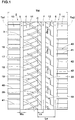
- Fig. 1 shows a tread portion 2 of a pneumatic tire 1 as an embodiment of the present invention.
- a pneumatic tire comprises a tread portion 2 whose radially outer surface defines the tread surface, a pair of axially spaced bead portions mounted on rim seats, a pair of sidewall portions extending between the tread edges and the bead portions, a carcass extending between the bead portions through the tread portion and the sidewall portions, and a tread reinforcement disposed radially outside the carcass in the tread portion.
- tread edges are the axial outermost edges of the ground contacting patch of the tire which occurs under a normally loaded condition when the camber angle of the tire is zero.
- the tread width TW is the width measured under a unloaded condition, as the axial distance between the tread edges determined as above.
- the unloaded condition of a pneumatic tire is such that the tire is mounted on a standard wheel rim and inflate to a standard pressure but loaded with no tire load.
- the normally loaded condition of a pneumatic tire is such that the tire is mounted on the standard wheel rim and inflated to the standard pressure and loaded with the standard tire load.
- the standard wheel rim is a wheel rim officially approved or recommended for the tire by standards organizations, i.e. JATMA (Japan and Asia), T&RA (North America), ETRTO (Europe), TRAA (Australia), STRO (Scandinavia), ALAPA (Latin America), ITTAC (India) and the like which are effective in the area where the tire is manufactured, sold or used.
- the standard pressure and the standard tire load are the maximum air pressure and the maximum tire load for the tire specified by the same organization in the Air-pressure/Maximum-load Table or similar list.
- the standard wheel rim is the "standard rim” specified in JATMA, the "Measuring Rim” in ETRTO, the "Design Rim” in TRA or the like.
- the standard pressure is the “maximum air pressure” in JATMA, the “Inflation Pressure” in ETRTO, the maximum pressure given in the “Tire Load Limits at various Cold Inflation Pressures” table in TRA or the like.
- the standard load is the "maximum load capacity" in JATMA, the “Load Capacity” in ETRTO, the maximum value given in the above-mentioned table in TRA or the like.
- the tread portion 2 of the tire is provided with a tread pattern of left-right asymmetry (asymmetry about the tire equator c).
- An example is shown in Fig. 1 .
- the mounting position of the tire with respect to a vehicle is specified.
- the sidewall portion (not shown) of the tire to be located on outside when installed on the vehicle is provided with an indication representing "outside”
- the sidewall portion (not shown) to be located on inside is provided with an indication representing "inside”.
- tread edges of the tread portion 2 are an outboard tread edge Te1 to be positioned away from the center of the vehicle body and an inboard tread edge Te2 to be positioned close to the center of the vehicle body.
- outboard and inboard are used toward the outboard tread edge and inboard tread edge, respectively, to refer relative positions in the tire axial direction.
- the tread portion 2 is provided, between the outboard tread edge Te1 and the inboard tread edge Te2, with three main grooves 3 extending continuously and circumferentially of the tire. Thereby, the tread portion 2 is axially divided into four annular land regions 4.
- the main grooves 3 are:
- the distance La in the tire axial direction from the tire equator C to the widthwise center line of the outboard shoulder main groove 5 is set in a range from 0.20 to 0.35 times the tread width TW.
- the distance La in the tire axial direction from the tire equator C to the widthwise center line of the inboard shoulder main groove 6 is set in a range from 0.20 to 0.35 times the tread width TW.
- the distance Lb in the tire axial direction from the tire equator C to the widthwise center line of the crown main groove 7 is set in a range of not more than 0.15 times the tread width TW.
- the crown main groove 7 is disposed on the inboard tread edge Te2 side of the tire equator C. However, it may be possible to dispose the crown main groove 7 at a different location.
- each of the three main grooves 3 is a straight groove parallel with the tire circumferential direction.
- the main groove 3 extends in a zigzag or wavy manner.
- the groove width Wa of each of the main grooves 3 is not less than 3.0 mm, preferably set in a range from 4.0% to 7.0% of the tread width TW, for example.
- a narrow groove whose groove width is less than 3.0 mm is not considered as a main groove.
- the groove width of a groove is a distance measured between the groove edges in a direction orthogonal to the widthwise center line.
- each of the main grooves 3 is set in a range from 5 to 10 mm, for example, in the case of a pneumatic tire for a passenger car.
- the four land regions 4 are an outboard middle land region 11, an inboard middle land region 12, an outboard shoulder land region 13, and a inboard shoulder land region 14.
- the outboard middle land region 11 is defined between the outboard shoulder main groove 5 and the crown main groove 7.
- the inboard middle land region 12 is defined between the inboard shoulder main groove 6 and the crown main groove 7.
- the outboard shoulder land region 13 is divided between the outboard shoulder main groove 5 and the outboard tread edge Te1.
- the inboard shoulder land region 14 is defined between the inboard shoulder main groove 6 and the inboard tread edge Te2.
- Fig. 2 shows a top view of a part of the outboard middle land region 11.
- the axial width w1 of the outboard middle land region 11 is largest among the four land regions 4.
- the outboard middle land region is subjected to a large ground contacting pressure during straight running and cornering.
- the outboard middle land region 11 has the largest axial width to have high rigidity, therefore, the outboard middle land region 11 in the present invention helps to improve the steering stability on dry road surfaces.
- the axial width w1 of the outboard middle land region 11 is set in a range from 0.25 to 0.35 times the tread width TW, for example.
- the outboard middle land region 11 is provided with first inclined grooves 16 and second inclined grooves 17 each inclined to a first direction with respect to the tire axial direction (downward to the right in Fig. 2 ).
- outboard middle land region 11 is provided with third inclined grooves 18 inclined to a second direction with respect to the tire axial direction (upward to the right in Fig. 2 ). which is opposite to the first direction,
- outboard middle land region 11 is provided with fourth inclined grooves 19 inclined to the second direction with respect to the tire axial direction.
- each inclined groove provided on the land region 11 can provide a large compacted snow block (snow column) and thereby can generate a larger shearing force when running on snow.
- the first inclined grooves 16 extend across the entire axial width of the outboard middle land region 11. Therefore, the first inclined groove 16 can produce an axially long snow block when running on snow, and thereby traction performance on snow can be improved.
- the second inclined grooves 17 extend from the crown main groove 7 toward the outboard shoulder main groove 5, but terminate within the outboard middle land region 11, without reaching the outboard shoulder main groove 5. Such second inclined grooves 17 can improve the performance on snow, while maintaining the rigidity of the outboard middle land region 11 and maintaining the steering stability on dry road surfaces.
- the angle of the widthwise center line of each of the first inclined grooves 16 with respect to the tire circumferential direction, and the angle of the widthwise center line of each of the second inclined grooves 17 with respect to the tire circumferential direction are gradually increased from the crown main groove 7 to the outboard tread edge Te1.
- the lateral rigidity of the outboard middle land region 11 is increased toward the outboard shoulder main groove 5, and the steering stability on dry road surfaces is improved.
- Each of the fourth inclined grooves 19 is connected to one of the second inclined grooves 17. Further, each of the fourth inclined grooves 19 is connected to one of the first inclined grooves 16 at a position on the outboard shoulder main groove 5 side of the midpoint of the length of the first inclined groove 16. During cornering, such fourth inclined grooves 19 form hard compacted snow blocks, particularly at the portions communicating with the first inclined grooves 16. This helps to improve the cornering performance on snowy road surfaces.
- the first inclined grooves 16 are each curved so that the widthwise center line curves to protrude toward one side in the tire circumferential direction (upward in Fig. 2 ) from a straight line drawn between both ends of the widthwise center line.
- the radius of curvature of the widthwise center line of the first inclined groove 16 is, for example, set in a range from 50 to 200 mm, and more preferably, 90 to 110 mm.
- the radius of curvature means that of an imaginary circular arc passing through three points at both ends of the widthwise center line and a midpoint of the length of the widthwise center line.
- the angle of the widthwise center line of the inclined groove 16 with respect to the tire circumferential direction is preferably, set in a range from 45 to 55 degrees, for example.
- Such first inclined grooves 16 can generate a snow block shearing force in multiple directions.
- the first inclined grooves 16 each have a groove width decreasing from the outboard shoulder main groove 5 toward the crown main groove 7, and the groove width at its end on the outboard shoulder main groove 5 side is larger than the groove width at its end on the crown main groove 7 side.
- the groove width at the end on the outboard shoulder main groove 5 side is set in a range from 6.0 to 8.0 mm, for example.
- the groove width at the end on the crown main groove 7 side is set in a range from 5.0 to 7.0 mm, for example.
- Fig. 3 is a cross-sectional view of the first inclined groove 16 taken along line A-A of Fig. 2 (widthwise center line).
- the first inclined groove 16 comprises an outer part 16a connected to the outboard shoulder main groove 5, and an inner part 16b connected to the crown main groove 7.
- the inner part 16b has a smaller depth than the outer part 16a.
- the depth d2 of the inner part 16b is set in a range from 0.40 to 0.70 times the depth d1 of the outer part 16a.
- the inner part 16b is formed on the crown main groove 7 side than the center in the tire axial direction of the outboard middle land region 11. Such inner parts 16b help to improve the steering stability on dry road surfaces.
- the second inclined grooves 17 extend across the axial or widthwise center line 11c of the outboard middle land region 11.
- the axial length L1 of the second inclined groove 17 is set in a range from 0.70 to 0.85 times the axial width w1 of the outboard middle land region 11, for example.
- Such second inclined grooves 17 help to improve the on-snow performance and the steering stability on dry road surfaces in a well-balanced manner.
- the second inclined grooves 17 are curved in the same direction as the first inclined grooves 16.
- the radius of curvature of the widthwise center line of each of the second inclined grooves 17 is smaller than the radius of curvature of the widthwise center line of each of the first inclined grooves 16.
- the difference in radius of curvature between the second inclined grooves 17 and the first inclined grooves 16 is in a range from 10 to 50 mm, for example.
- the radius of curvature of the second inclined grooves 17 is set in a range from 50 to 200 mm, and more preferably, 80 to 110 mm.
- the angle of the widthwise center line of each of the second inclined grooves 17 with respect to the tire circumferential direction is set in a range from 45 to 55 degrees, for example.
- the second inclined grooves 17 each have a groove width decreasing from the crown main groove 7 toward the outboard shoulder main groove 5, and the groove width at its end on the crown main groove 7 side is larger than the groove width at its terminal end positioned within the outboard middle land region 11.
- the groove width at the end on the crown main groove 7 side is set in a range from 10.0 to 12.0 mm, for example.
- the groove width at the terminal end is set in a range from 1.0 to 3.0 mm, for example.
- the groove width at the terminal end is measured at a position excluding the arc-shaped edge at the terminal end.
- the second inclined grooves 17 together with the first inclined grooves 16 provide a large snow block shearing force, while maintaining the rigidity of the outboard middle land region 11.
- each of the second inclined grooves 17 in the present embodiment is gradually decreased from the crown main groove 7 to its terminal end positioned within the outboard middle land region 11.
- Such second inclined grooves 17 can further suppress the decrease in the rigidity of the outboard middle land region 11.
- the opening width w5 of the second inclined groove 17 to the crown main groove 7 is larger than the opening width w4 of the first inclined groove 16 to the outboard shoulder main groove 5.
- the opening width w5 is in a range from 1.2 to 1.5 times the opening width w4. This makes it easier for water existing in the second inclined grooves 17 to be discharged toward the outboard shoulder main groove 5 through the first inclined grooves 16 during running in wet conditions.
- Fig. 4 is a cross sectional view of the second inclined groove 17 taken along line B-B of Fig. 2 (widthwise center line).
- each of the second inclined grooves 17 is gradually decreased from the crown main groove 7 toward the outboard shoulder main groove 5 as shown in Fig. 4 .
- Such second inclined grooves 17 together with the first inclined grooves 16 improve the performance on snow and the steering stability on dry road surfaces in a well-balanced manner.
- the second inclined groove 17 comprises a first constant depth portion 17a, a second constant depth portion 17b, and a variable depth portion 17c therebetween.
- the first constant depth portion 17a has a constant depth along its length and is connected to the crown main groove 7.
- the first constant depth portion 17a has the same depth as the outer part 16a of the first inclined groove 16 shown in Fig. 3 .
- the second constant depth portion 17b is disposed on the outboard shoulder main groove 5 side of the first constant depth portion 17a.
- the second constant depth portion 17b has a constant depth d4 along its length, and the constant depth d4 is a smaller depth than that of the first constant depth portion 17a.
- the second constant depth portion 17b has the same depth as the inner part 16b of the first inclined groove 16.
- the depth d4 of the second constant depth portion 17b is, for example, set in a range from 0.40 to 0.70 times the depth d3 of the first constant depth portion 17a.
- variable depth portion 17c has a bottom surface inclined with respect to the tire axial direction, and the depth gradually decreases from the first constant depth portion 17a to the second constant depth portion 17b.
- At least one of the third inclined grooves 18 is connected to one of the first inclined grooves 16 and one of the second inclined grooves 17.
- each of the third inclined grooves 18 extends from the outboard shoulder main groove 5 and intersects one of the first inclined grooves 16 and then meets intersects one of the second inclined grooves 17 without intersecting as shown in Fig. 2 .
- the third inclined grooves 18 respectively intersect the first inclined grooves 16 and meet the second inclined grooves 17 on the crown main groove 7 side of the axial or widthwise center line 11c of the outboard middle land region 11.
- the third inclined groove 18 intersects a variable depth portion (shown in Fig. 3 ) of the first inclined groove 16.
- the third inclined groove 18 is connected to the first constant depth portion 17a (shown in Fig. 4 ) of the second inclined groove 17. when running on snow, such third inclined grooves 18 can strongly compact the snow in the intersecting portions with the first inclined grooves 16 and the second inclined grooves 17 and can further improve the performance on snow.
- the third inclined grooves 18 extend from the outboard shoulder main groove 5 toward the crown main groove 7, and preferably extend across the axial center line 11c.
- the third inclined grooves 18 respectively cross the first inclined grooves 16 on the crown main groove 7 side of the axial center line 11c.
- the angle ⁇ 1 between the widthwise center line of the first inclined groove 16 and the widthwise center line of the third inclined groove 18 is set in a range from 40 to 55 degrees, for example.
- Each of the third inclined grooves 18 is connected to one of the second inclined grooves 17 near the end on the crown main groove side 7 of the second inclined groove 17, and terminates without crossing the second inclined groove 17.
- the third inclined groove 18 is curved so that the groove widthwise center line protrudes from a straight line drawn between both ends of the widthwise center line toward the other side in the tire circumferential direction than that of the first inclined grooves 16 (downward in Fig. 2 ).
- the radius of curvature of the widthwise center line of the third inclined groove 18 is larger than the radius of curvature of the widthwise center line of the first inclined groove 16.
- the difference in radius of curvature between the third inclined grooves 18 and the first inclined grooves 16 is, for example, 50 to 200 mm.
- the radius of curvature of the widthwise center line of the third inclined groove 18 is 150 to 450 mm, for example.
- the angle of the widthwise center line of the third inclined groove 18 with respect to the tire circumferential direction gradually decreases toward the crown main groove 7.
- the angle is set in a range from 60 to 80 degrees, for example.
- the angle between the widthwise center lines of the outboard shoulder main groove 5 and the third inclined groove 18 is larger than the angle between the widthwise center lined of the crown main groove 7 and the first inclined groove 16.
- the groove width of the third inclined groove 18 is constant along its length.
- the groove width is set in a range from 2.0 to 3.0 mm, for example.
- the depth of the third inclined groove 18 is constant along its length.
- the depth of the third inclined grooves 18 is smaller than the depth of the outer part 16a of the first inclined grooves 16 and the depth of the first constant depth portion 17a of the second inclined grooves 17.
- the depth of the third inclined grooves 18 is the same as the depth of the inner part 16b of the first inclined groove 16 and the depth of the second constant depth portion 17b of the second inclined groove 17.
- the bottom surface of the third inclined groove 18 may be provided with a sipe (not shown) extending along the length of the third inclined groove 18.
- the term "sipe” means a narrow groove having a width not more than 1.5 mm inclusive of a cut having no substantial width.
- the third inclined grooves 18 provided with the sipes can improve the steering stability on dry road surfaces while maintaining the performance on snow.
- the above-mentioned fourth inclined grooves 19 are respectively connected to the first inclined grooves 16 at an axial position on the outboard shoulder main groove 5 side than the ends on the outboard shoulder main groove 5 side of the second inclined grooves 17.
- the fourth inclined groove 19 is connected to the outer part 16a (shown in Fig. 3 ) of the first inclined groove 16.
- the axial distance L2 (shown in Fig. 2 ) from a position at which the widthwise center line of the fourth inclined groove 19 intersects the first inclined groove 16 (groove edge) to the outboard shoulder main groove 5 (groove edge), the axial distance L2 is preferably set in a range from 0.05 to 0.20 times the axial width w1 of the outboard middle land region 11.
- the fourth inclined grooves 19 extend across the axial center line 11c. And the fourth inclined grooves 19 respectively intersect with the second inclined grooves 17 on the crown main groove 7 side of the axial center line 11c. In the present embodiment, the fourth inclined groove 19 intersects the first constant depth portion 17a (shown in Fig. 4 ) of the second inclined groove 17. The ends on the crown main groove side 7 of the fourth inclined grooves 19 terminate within the outboard middle land region 11. Therefore, the fourth inclined grooves 19 intersect the deeper portions of the first inclined grooves 16 and the second inclined grooves 17, and can form hard snow blocks (columns) at the intersections of the grooves.
- the axial length of the fourth inclined groove 19 is smaller than the axial length of the third inclined groove 18. Such fourth inclined grooves 19 can improve the performance on snow, while maintaining the rigidity of the outboard middle land region 11.
- the fourth inclined grooves 19 are preferably convexly curved in the same direction as the third inclined grooves 18.
- the radius of curvature of the widthwise center line of the fourth inclined groove 19 is set in a range from 150 to 450 mm, for example.
- the radius of curvature of the fourth inclined grooves 19 is the same as that of the third inclined grooves 18.
- Such fourth inclined grooves 19 can further maintain the rigidity of the outboard middle land region 11.
- the angle between the fourth inclined groove 19 and the outboard shoulder main groove 5 is larger than the angle between the first inclined groove 16 and the crown main groove 7, and larger than the angle between the second inclined groove 17 and the crown main groove 7.
- the angle between the fourth inclined groove 19 and the outboard shoulder main groove 5 is set in a range from 60 to 80 degrees, for example.
- the angle ⁇ 2 between the first inclined groove 16 and the fourth inclined groove 19 is set in a range from 45 to 55 degrees, for example.
- each angle is between the grooves' widthwise center lines.
- the groove width of the fourth inclined groove 19 is constant along its length. It is preferable that the groove width of the fourth inclined grooves 19 is larger than the groove width of the third inclined grooves 18, and smaller than the maximum groove width of the first inclined grooves 16. It is preferable that the maximum depth of the fourth inclined grooves 19 is larger than the maximum depth of the third inclined grooves 18. Such fourth inclined grooves 19 can improve the on-snow performance and the steering stability on dry road surfaces in a well-balanced manner.
- the tip portion 19a on the crown main groove 7 side of the intersecting second inclined groove 17 is smaller in the groove depth than its main portion 19b on the outboard shoulder main groove 5 side of the second inclined groove 17.
- Such fourth inclined grooves 19 help to improve the steering stability on dry road surfaces.
- the outboard middle land region 11 in the present embodiment is provided with fifth inclined grooves 20.
- the fifth inclined grooves 20 meet the respective first inclined grooves 16 without intersecting, so as to form T-junctions. Further, the fifth inclined grooves 20 meet the respective second inclined grooves 17 without intersecting, so as to form T-junctions. However, the present invention is not limited to such T-junctions, and the fifth inclined grooves 20 may intersect the first inclined grooves 16 and/or the second inclined grooves 17 to form cross junctions.
- the fifth inclined grooves 20 meet the first inclined grooves 16 on the crown main groove 7 side of the axial center line 11c.
- the fifth inclined grooves 20 meet the second inclined grooves 17 on the outboard shoulder main groove 5 side of the axial center line 11c.
- the fifth inclined grooves 20 extend across the axial center line 11c.
- the fifth inclined groove 20 meets the inner part 16b (shown in Fig. 3 ) of the first inclined groove 16, and meets the second constant depth portion 17b (shown in Fig. 4 ) of the second inclined groove 17.
- each of the fifth inclined grooves 20 is smaller than that of the fourth inclined grooves 19.
- the fifth inclined grooves 20 are inclined to the above-said second direction with respect to the tire axial direction.
- the fifth inclined grooves 20 extend parallel with the fourth inclined grooves 19.
- the angle ⁇ 3 between the widthwise center lines of the second inclined groove 17 and the fifth inclined groove 20 is preferably set in a range from 45 to 55 degrees.
- the fifth inclined grooves 20 are curved in the same direction as the third inclined grooves 18.
- the radius of curvature of the widthwise center line of the fifth inclined groove 20 is larger than the radius of curvature of the widthwise center line of the first inclined groove 16 and the radius of curvature of the widthwise center line of the second inclined groove 17.
- the radius of curvature of the fifth inclined groove 20 is set in a range from 180 to 440 mm.
- the groove width of the fifth inclined grooves 20 is constant along its length. It is preferable that the groove width of the fifth inclined grooves 20 is larger than the groove width of the fourth inclined grooves 19 and smaller than the maximum groove width of the first inclined grooves 16. Further, it is preferable that the maximum depth of the fifth inclined grooves 20 is smaller than the maximum depth of the fourth inclined grooves 19.
- the outboard middle land region 11 in the present embodiment is preferably provided with sipes 25 in order to improve on-snow performance and wet performance.
- the width of the sipes 25 is set in a range from 0.4 to 1.0 mm, for example.
- the sipes 25 are inclined to the second direction with respect to the tire axial direction. Further, the sipes 25 are preferably convexly curved in the same direction as the third inclined grooves 18. Such sipes 25 provide large frictional force by their edges while maintaining the rigidity of the outboard middle land region 11.
- the sipes 25 in the present embodiment are:
- Each of the first sipes 26 extends from the outboard shoulder main groove 5, and intersects one of the first inclined grooves 16, and extends through between the adjacent third inclined groove 18 and fourth inclined groove 19, and then meets one of the second inclined grooves 17 without intersecting, on the crown main groove 7 side of the axial center line 11c.
- the first sipes 26 extend parallel with the third inclined grooves 18.
- Each of the second sipes 27 extends from the outboard shoulder main groove 5 through between the adjacent third inclined groove 18 and fourth inclined groove 19, and meets one of the second inclined grooves 17 without intersecting, on the outboard shoulder main groove 5 side of the axial center line 11c.
- the second sipe 27 meets an extension of the fifth inclined groove 20 toward the outboard shoulder main groove 5.
- the second sipes 27 extend parallel with the fourth inclined grooves 19.
- Each of the third sipes 28 is disposed between the adjacent first inclined groove 16 and second inclined groove 17, on the crown main groove 7 side of the axial center line 11c.
- Each of the third sipes 28 extends from the crown main groove 7 toward the outboard shoulder main groove 5 and meets one of the first inclined grooves 16 without intersecting.
- the third sipe 28 meets an extension of the fifth inclined groove 20 toward the crown main groove 7.
- the third sipes 28 extend parallel with the third inclined grooves 18.
- Each of the fourth sipes 29 is disposed on the crown main groove 7 side of the axial center line 11c and extends from one of the first inclined grooves 16 to the end of one the fourth inclined grooves 19.
- the fourth sipes 29 extend parallel with the fifth inclined grooves 20.
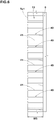
- Fig. 5 shows a part of the inboard middle land region 12.
- the axial width w2 of the inboard middle land region 12 is preferably set in a range from 0.10 to 0.20 times the tread width TW, for example.
- the inboard middle land region 12 in this example is provided with middle lateral grooves 30 extending from the crown main groove 7 and terminated within the inboard middle land region 12.
- the middle lateral groove 30 comprises
- the inboard middle land region 12 is further provided with first middle sipes 33 and second middle sipes 34.
- the first middle sipes 33 extend from the crown main groove 7 and terminate within the inboard middle land region 12.
- the second middle sipes 34 extend from the inboard shoulder main groove 6, and meet the respective middle lateral grooves 30.
- the inboard middle land region 12 in the present embodiment is further provided with a sipe combination 35 made up of two sipes 36 and multiple cuts extending between the two sipes 36.
- the two sipes 36 in this example extend from one of the first middle sipes 33 to the first portion 31 of one of the middle lateral grooves 30, while gradually decreasing the distance therebetween.
- the sipe combination 35 is provided for every other first middle sipe 33 as shown in Fig. 5 .
- Such sipe combination 35 helps to improve grip performance at the start of use of the tire.
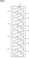
- Fig. 6 shows a part of the outboard shoulder land region 13.
- the axial width w3 of the outboard shoulder land region 13 is larger than the axial width w2 of the inboard middle land region 12 as shown in Fig. 1 .
- the axial width w3 is set in a range from 0.15 to 0.25 times the tread width TW, for example.
- the outboard shoulder land region 13 is provided with shoulder lateral grooves 40 extending in the tire axial direction, and shoulder sipes 41 extending in the tire axial direction.
- shoulder lateral grooves 40 and shoulder sipes 41 help to improve the performance on snow.
- the inboard shoulder land region 14 is also provided with shoulder lateral grooves 40 extending in the tire axial direction, and shoulder sipes 41 extending in the tire axial direction as shown in Fig. 1 .
- the inboard shoulder land region 14 is provided with a chamfer 42 extending between the ground contacting top surface of the inboard shoulder land region 14 (constituting a part of the tread surface) and the side surface on the inboard shoulder main groove 6 side of the inboard shoulder land region 14.
- the chamfer 42 is provided with narrow grooves (not shown) extending from the tread surface to the above-said side surface. Thereby, grip performance on snow can be further improved.
- Pneumatic tires of size 215/60R16 were experimentally manufactured as test tires including:
- test tire was tested for on-snow performance and steering stability on dry road surfaces as follows, using a 2500cc front wheel drive passenger car as a test car where the test tires were mounted on standard wheel rims of size 16x6.5 and inflated to 240 kPa.
- Table 1 Tire Com Ex.1 Ex.2 Ex.3 Ex.4 Ex.5 Ex.6 Ex.7 Ex.8 Ex.9 outboard middle land region (Fig.No.) 7 2 2 2 2 2 2 2 2 2 2 W1/TW 0.30 0.30 0.25 0.28 0.32 0.35 0.30 0.30 0.30 0.30 0.30 L2/W1 - 0.12 0.12 0.12 0.12 0.05 0.10 0.15 0.20 on-snow performance 100 107 107 107 106 105 108 107 107 105 steering stability 100 102 101 102 103 103 100 101 102 102 102
- Pneumatic tires of size 215/60R16 were experimentally manufactured as test tires including:
- test tire was tested for on-snow performance and steering stability on dry road surfaces in the same manner as described above.
- the test results are shown in Table 2 by an index based on the reference example tire Ref.1 being 100, wherein the larger the numerical value, the better the performance.
- Pneumatic tires of size 215/60R16 were experimentally manufactured as test tires including:
- test tire was tested for steering stability on dry road surfaces in the same manner as described above.
- the test results are shown in Table 3 by an index based on the reference example tire Ref.2 being 100, wherein the larger the numerical value, the better the performance.
- each test tire was tested for wet performance as follows.
Landscapes
- Engineering & Computer Science (AREA)
- Mechanical Engineering (AREA)
- Tires In General (AREA)
Abstract
Description
- The present invention relates to a tire, more particularly to a tire having a tread portion axially divided into four land regions.
- Japanese Patent Application Publication No.
2015-120380 Patent Document 1, the arrangement of grooves disposed in the outboard middle land region is specifically defined with the view to improvement in on-snow performance, while suppressing a decrease in the rigidity of the outboard middle land region. - In the tire of
Patent Document 1, however, the outboard middle land region has a tendency that the lateral rigidity thereof becomes insufficient. This leads to deterioration in the steering stability on dry road surfaces. Therefore, the tire is required to be improved in the steering stability on dry road surfaces. - The present invention was made in view of the above-described problems, and it is an objective of the present invention to proved a tire of which tread portion is axially divided into four land regions and which can exhibit excellent on-snow performance and steering stability on dry road surfaces.
- According to one aspect of the present invention, a tire whose mounting direction to a vehicle is specified, comprises:
- a tread portion having an outboard tread edge and an inboard tread edge to be located outboard and inboard of the vehicle, respectively, when the tire is mounted on the vehicle,
- the tread portion provided, between the inboard tread edge and the outboard tread edge, with three main grooves,
- the three main grooves extending continuously and circumferentially of the tire so that the tread portion is axially divided into four land regions,
- the three main grooves including
an outboard shoulder main groove disposed closest to the outboard tread edge among the three main grooves, and
a crown main groove disposed adjacently to the outboard shoulder main groove on the inboard tread edge side of the outboard shoulder main groove, and - the four land regions including
an outboard middle land region defined between the outboard shoulder main groove and the crown main groove,
wherein - the axial width of the outboard middle land region is the largest among the four land regions,
- the outboard middle land region is provided with
first inclined grooves each inclined to a first direction with respect to the tire axial direction,
second inclined grooves each inclined to the first direction with respect to the tire axial direction, and
fourth inclined groove inclined to a second direction with respect to the tire axial direction, the second direction being opposite to the first direction, - the first inclined grooves extend across the entire axial width of the outboard middle land region,
- the second inclined grooves extend from the crown main groove and are terminated within the outboard middle land region,
- an angle of each of the first inclined grooves with respect to the tire circumferential direction gradually increases from the crown main groove toward the outboard tread edge,
- an angle of each of the second inclined grooves with respect to the tire circumferential direction gradually increases from the crown main groove toward the outboard tread edge, and
- each of the fourth inclined grooves intersects one of the second inclined grooves, and intersects one of the adjacent first inclined grooves at a position on the outboard shoulder main groove side of the midpoint of the length of the first inclined groove.
- In this application, when a groove is expressed as being connected to another groove, it is intended to mean either the two grooves intersecting with each other to form a cross junction, or the two grooves one of which meets the other, without intersecting, to form a T or Y junction.
- According to another aspect of the present invention, a tire whose mounting direction to a vehicle is specified, comprises:
- a tread portion having an outboard tread edge and an inboard tread edge to be located outboard and inboard of the vehicle, respectively, when the tire is mounted on the vehicle,
- the tread portion provided, between the inboard tread edge and the outboard tread edge, with three main grooves,
- the three main grooves extending continuously and circumferentially of the tire so that the tread portion is axially divided into four land regions,
- the three main grooves including
an outboard shoulder main groove disposed closest to the outboard tread edge among the three main grooves, and
a crown main groove disposed adjacently to the outboard shoulder main groove on the inboard tread edge side of the outboard shoulder main groove, and - the four land regions including an outboard middle land region defined between the outboard shoulder main groove and the crown main groove,
wherein - the axial width of the outboard middle land region is the largest among the four land regions,
- the outboard middle land region is provided with
first inclined grooves each inclined to a first direction with respect to the tire axial direction,
second inclined grooves each inclined to the first direction with respect to the tire axial direction, and
third inclined groove inclined to a second direction with respect to the tire axial direction, the second direction being opposite to the first direction, - the first inclined grooves extend across the entire axial width of the outboard middle land region,
- the second inclined grooves extend from the crown main groove and are terminated within the outboard middle land region,
- an angle of each of the first inclined grooves with respect to the tire circumferential direction gradually increases from the crown main groove toward the outboard tread edge,
- an angle of each of the second inclined grooves with respect to the tire circumferential direction gradually increases from the crown main groove toward the outboard tread edge, and
- at least one of the third inclined grooves intersects with one of the first inclined grooves and then intersects one of the second inclined grooves.
- According to still another aspect of the present invention, a tire whose mounting direction to a vehicle is specified, comprises:
- a tread portion having an outboard tread edge and an inboard tread edge to be located outboard and inboard of the vehicle, respectively, when the tire is mounted on the vehicle,
- the tread portion provided, between the inboard tread edge and the outboard tread edge, with three main grooves,
- the three main grooves extending continuously and circumferentially of the tire so that the tread portion is axially divided into four land regions,
- the three main grooves including
an outboard shoulder main groove disposed closest to the outboard tread edge among the three main grooves, and
a crown main groove disposed adjacently to the outboard shoulder main groove on the inboard tread edge side of the outboard shoulder main groove, and - the four land regions including an outboard middle land region defined between the outboard shoulder main groove and the crown main groove,
wherein - the axial width of the outboard middle land region is the largest among the four land regions,
- the outboard middle land region is provided with
first inclined grooves each inclined to a first direction with respect to the tire axial direction,
second inclined grooves each inclined to the first direction with respect to the tire axial direction, and
fifth inclined groove inclined to a second direction with respect to the tire axial direction, the second direction being opposite to the first direction, - the first inclined grooves extend across the entire axial width of the outboard middle land region,
- the second inclined grooves extend from the crown main groove and are terminated within the outboard middle land region,
- an angle of each of the first inclined grooves with respect to the tire circumferential direction gradually increases from the crown main groove toward the outboard tread edge,
- an angle of each of the second inclined grooves with respect to the tire circumferential direction gradually increases from the crown main groove toward the outboard tread edge, and
- each of the fifth inclined grooves extends to one of the first inclined grooves to terminate without extending thereacross, and extends to one of the second inclined grooves to terminate without extending thereacross.
- It is preferable that the fourth inclined grooves respectively extend across the second inclined grooves.
- It is preferable that ends on the crown main groove side of the fourth inclined grooves are terminated within the outboard middle land region.
- It is preferable that the fourth inclined grooves are respectively connected to the first inclined grooves on the outboard shoulder main groove side than ends on the outboard shoulder main groove side of the second inclined grooves.
- It is preferable that the first inclined grooves each have a groove width decreasing from the outboard shoulder main groove toward the crown main groove.
- It is preferable that the second inclined grooves each have a groove width decreasing from the crown main groove toward the outboard shoulder main groove.
- It is preferable that each of the first inclined grooves and the second inclined grooves is curved, and the radius of curvature of the widthwise center line of the second inclined groove is smaller than the radius of curvature of the widthwise center line of the first inclined groove.
- It is preferable that the outboard middle land region is provided with third inclined grooves inclined to the above-said second direction with respect to the tire axial direction.
- It is preferable that each of the third inclined grooves extends from the outboard shoulder main groove to one of the second inclined grooves across one of the first inclined grooves.
- It is preferable that each of the first inclined grooves and the third inclined grooves is curved, and the radius of curvature of the widthwise center line of the third inclined groove is larger than the radius of curvature of the widthwise center line of the first inclined groove.
- It is preferable that the angle between the widthwise center line of the outboard shoulder main groove and the widthwise center line of each of the third inclined grooves is larger than the angle between the widthwise center line of the crown main groove and the widthwise center line of each of the first inclined grooves.
- It is preferable that the crown main groove is disposed between the tire equator and the inboard tread edge.
- It is preferable that the outboard middle land region is provided with fifth inclined grooves inclined to the above-said second direction with respect to the tire axial direction, and
each of the fifth inclined grooves extends to one of the first inclined grooves to terminate without extending thereacross, and extends to one of the second inclined grooves to terminate without extending thereacross. - It is preferable that the outboard middle land region is provided with:
- third inclined grooves inclined to the second direction with respect to the tire axial direction, wherein each of the third inclined grooves extends from the outboard shoulder main groove and intersects one of the first inclined grooves and then intersects one of the second inclined grooves; and
- fifth inclined grooves inclined to the second direction with respect to the tire axial direction, wherein each of the fifth inclined grooves extends to one of the first inclined grooves to terminate without extending thereacross, and extends to one of the second inclined grooves to terminate without extending thereacross.
- It is preferable that the outboard middle land region is provided with:
- third inclined grooves inclined to the second direction with respect to the tire axial direction, wherein each of the third inclined grooves extends from the outboard shoulder main groove and intersects one of the first inclined grooves and then intersects one of the second inclined grooves;
- fifth inclined grooves inclined to the second direction with respect to the tire axial direction, wherein each of the fifth inclined grooves extends to one of the first inclined grooves to terminate without extending thereacross, and extends to one of the second inclined grooves to terminate without extending thereacross, and
- the crown main groove is disposed between the tire equator and the inboard tread edge.
- It is preferable that the fifth inclined grooves are respectively connected to the first inclined grooves on the crown main groove side of the axial center line of the outboard middle land region.
- It is preferable that the fifth inclined grooves are respectively connected to the second inclined grooves on the outboard shoulder main groove side of the axial center line of the outboard middle land region.
- It is preferable that the first inclined grooves, the second inclined grooves, and the fifth inclined grooves are each curved, and
the radius of curvature of the widthwise center line of each of the fifth inclined grooves is larger than the radius of curvature of the widthwise center line of each of the first inclined grooves, and larger than the radius of curvature of the widthwise center line of each of the second inclined grooves. -
-
Fig. 1 is a developed partial view of the tread portion of a tire as an embodiment of the present invention. -
Fig. 2 is a top view of a part of the outboard middle land region shown inFig. 1 . -
Fig. 3 is a cross sectional view taken along line A-A ofFig. 2 . -
Fig. 4 is a cross sectional view taken along line B-B ofFig. 2 . -
Fig. 5 is a top view of a part of the inboard middle land region shown inFig. 1 . -
Fig. 6 is a top view of a part of the outboard shoulder land region shown inFig. 1 . -
Fig. 7 is a top view of a part of the tread portion of a tire as a comparative example. -
Fig. 8 is a top view of a part of the tread portion of a tire as a reference example 1. -
Fig. 9 is a top view of a part of the tread portion of a tire as a reference example 2. - The present invention can be applied to various tiers such as pneumatic tires as well as non-pneumatic tires so called airless tire, for various vehicles. e.g. a passenger car and a heavy-duty vehicle such as truck and bus and the like.
- Hereinafter, taking a pneumatic tire for a passenger car as an example, embodiments of the present invention will be described in detail conjunction with accompanying drawings.
-
Fig. 1 shows atread portion 2 of apneumatic tire 1 as an embodiment of the present invention. - As well known in the art, a pneumatic tire comprises a
tread portion 2 whose radially outer surface defines the tread surface, a pair of axially spaced bead portions mounted on rim seats, a pair of sidewall portions extending between the tread edges and the bead portions, a carcass extending between the bead portions through the tread portion and the sidewall portions, and a tread reinforcement disposed radially outside the carcass in the tread portion. - The tread edges are the axial outermost edges of the ground contacting patch of the tire which occurs under a normally loaded condition when the camber angle of the tire is zero.
- The tread width TW is the width measured under a unloaded condition, as the axial distance between the tread edges determined as above.
- The unloaded condition of a pneumatic tire is such that the tire is mounted on a standard wheel rim and inflate to a standard pressure but loaded with no tire load.
- The normally loaded condition of a pneumatic tire is such that the tire is mounted on the standard wheel rim and inflated to the standard pressure and loaded with the standard tire load.
- The standard wheel rim is a wheel rim officially approved or recommended for the tire by standards organizations, i.e. JATMA (Japan and Asia), T&RA (North America), ETRTO (Europe), TRAA (Australia), STRO (Scandinavia), ALAPA (Latin America), ITTAC (India) and the like which are effective in the area where the tire is manufactured, sold or used.
The standard pressure and the standard tire load are the maximum air pressure and the maximum tire load for the tire specified by the same organization in the Air-pressure/Maximum-load Table or similar list.
For example, the standard wheel rim is the "standard rim" specified in JATMA, the "Measuring Rim" in ETRTO, the "Design Rim" in TRA or the like. The standard pressure is the "maximum air pressure" in JATMA, the "Inflation Pressure" in ETRTO, the maximum pressure given in the "Tire Load Limits at various Cold Inflation Pressures" table in TRA or the like. The standard load is the "maximum load capacity" in JATMA, the "Load Capacity" in ETRTO, the maximum value given in the above-mentioned table in TRA or the like. - In this application including specification and claims, various dimensions, positions and the like of a pneumatic tire refer to those under the unloaded condition of the tire unless otherwise noted.
- According to the present invention, the
tread portion 2 of the tire is provided with a tread pattern of left-right asymmetry (asymmetry about the tire equator c). An example is shown inFig. 1 .
Thus, the mounting position of the tire with respect to a vehicle is specified. For example, the sidewall portion (not shown) of the tire to be located on outside when installed on the vehicle is provided with an indication representing "outside", and the sidewall portion (not shown) to be located on inside is provided with an indication representing "inside". - The above-said tread edges of the
tread portion 2 are an outboard tread edge Te1 to be positioned away from the center of the vehicle body and an inboard tread edge Te2 to be positioned close to the center of the vehicle body. - According thereto, in this application, the terms "outboard" and "inboard" are used toward the outboard tread edge and inboard tread edge, respectively, to refer relative positions in the tire axial direction.
- The terms "axially inner", "axially inward" and the like are used toward the tire equator, and the terms "axially outer", "axially outward" and the like are used toward the tread edge in order to refer relative positions in the tire axial direction.
- In order to form the tread pattern, the
tread portion 2 is provided, between the outboard tread edge Te1 and the inboard tread edge Te2, with threemain grooves 3 extending continuously and circumferentially of the tire. Thereby, thetread portion 2 is axially divided into fourannular land regions 4. - The
main grooves 3 are: - an outboard shoulder
main groove 5 disposed between the outboard tread edge Te1 and the tire equator C and being closest to the outboard tread edge Te1 among the threemain grooves 3; - an inboard shoulder
main groove 6 disposed between the inboard tread edge Te2 and the tire equator C and being closest to the inboard tread edge Te2 among the threemain grooves 3; and - a crown
main groove 7 disposed between the outboard shouldermain groove 5 and the inboard shouldermain groove 6. - It is preferable that the distance La in the tire axial direction from the tire equator C to the widthwise center line of the outboard shoulder
main groove 5 is set in a range from 0.20 to 0.35 times the tread width TW. - It is preferable that the distance La in the tire axial direction from the tire equator C to the widthwise center line of the inboard shoulder
main groove 6 is set in a range from 0.20 to 0.35 times the tread width TW. - It is preferable that the distance Lb in the tire axial direction from the tire equator C to the widthwise center line of the crown
main groove 7 is set in a range of not more than 0.15 times the tread width TW. - In the present embodiment, the crown
main groove 7 is disposed on the inboard tread edge Te2 side of the tire equator C. However, it may be possible to dispose the crownmain groove 7 at a different location. - In the present embodiment, each of the three
main grooves 3 is a straight groove parallel with the tire circumferential direction. However, it may be possible that themain groove 3 extends in a zigzag or wavy manner. - The groove width Wa of each of the
main grooves 3 is not less than 3.0 mm, preferably set in a range from 4.0% to 7.0% of the tread width TW, for example. - In the present invention, a narrow groove whose groove width is less than 3.0 mm is not considered as a main groove. Incidentally, the groove width of a groove is a distance measured between the groove edges in a direction orthogonal to the widthwise center line.
- It is preferable that the depth of each of the
main grooves 3 is set in a range from 5 to 10 mm, for example, in the case of a pneumatic tire for a passenger car. - The four
land regions 4 are an outboardmiddle land region 11, an inboardmiddle land region 12, an outboardshoulder land region 13, and a inboardshoulder land region 14. The outboardmiddle land region 11 is defined between the outboard shouldermain groove 5 and the crownmain groove 7. The inboardmiddle land region 12 is defined between the inboard shouldermain groove 6 and the crownmain groove 7. The outboardshoulder land region 13 is divided between the outboard shouldermain groove 5 and the outboard tread edge Te1. The inboardshoulder land region 14 is defined between the inboard shouldermain groove 6 and the inboard tread edge Te2. -
Fig. 2 shows a top view of a part of the outboardmiddle land region 11. - As shown in
Fig. 1 andFig. 2 , the axial width w1 of the outboardmiddle land region 11 is largest among the fourland regions 4. - In general, when the tread portion is made up of four land regions as in the present invention, the outboard middle land region is subjected to a large ground contacting pressure during straight running and cornering.
In the present invention, the outboardmiddle land region 11 has the largest axial width to have high rigidity, therefore, the outboardmiddle land region 11 in the present invention helps to improve the steering stability on dry road surfaces. - Preferably, the axial width w1 of the outboard
middle land region 11 is set in a range from 0.25 to 0.35 times the tread width TW, for example. - The outboard
middle land region 11 is provided with firstinclined grooves 16 and secondinclined grooves 17 each inclined to a first direction with respect to the tire axial direction (downward to the right inFig. 2 ). - Further, the outboard
middle land region 11 is provided with thirdinclined grooves 18 inclined to a second direction with respect to the tire axial direction (upward to the right inFig. 2 ). which is opposite to the first direction, - Further. the outboard
middle land region 11 is provided with fourthinclined grooves 19 inclined to the second direction with respect to the tire axial direction. - Since a large ground contacting pressure acts on the outboard
middle land region 11, each inclined groove provided on theland region 11 can provide a large compacted snow block (snow column) and thereby can generate a larger shearing force when running on snow. - The first
inclined grooves 16 extend across the entire axial width of the outboardmiddle land region 11. Therefore, the firstinclined groove 16 can produce an axially long snow block when running on snow, and thereby traction performance on snow can be improved. - The second
inclined grooves 17 extend from the crownmain groove 7 toward the outboard shouldermain groove 5, but terminate within the outboardmiddle land region 11, without reaching the outboard shouldermain groove 5.
Such secondinclined grooves 17 can improve the performance on snow, while maintaining the rigidity of the outboardmiddle land region 11 and maintaining the steering stability on dry road surfaces. - The angle of the widthwise center line of each of the first
inclined grooves 16 with respect to the tire circumferential direction, and
the angle of the widthwise center line of each of the secondinclined grooves 17 with respect to the tire circumferential direction
are gradually increased from the crownmain groove 7 to the outboard tread edge Te1. As a result, the lateral rigidity of the outboardmiddle land region 11 is increased toward the outboard shouldermain groove 5, and the steering stability on dry road surfaces is improved. - Each of the fourth
inclined grooves 19 is connected to one of the secondinclined grooves 17.
Further, each of the fourthinclined grooves 19 is connected to one of the firstinclined grooves 16 at a position on the outboard shouldermain groove 5 side of the midpoint of the length of the firstinclined groove 16. During cornering, such fourthinclined grooves 19 form hard compacted snow blocks, particularly at the portions communicating with the firstinclined grooves 16. This helps to improve the cornering performance on snowy road surfaces. - The first
inclined grooves 16 are each curved so that the widthwise center line curves to protrude toward one side in the tire circumferential direction (upward inFig. 2 ) from a straight line drawn between both ends of the widthwise center line. - The radius of curvature of the widthwise center line of the first
inclined groove 16 is, for example, set in a range from 50 to 200 mm, and more preferably, 90 to 110 mm. - If the widthwise center line of the inclined groove is not an accurate circular arc, the radius of curvature means that of an imaginary circular arc passing through three points at both ends of the widthwise center line and a midpoint of the length of the widthwise center line.
- The angle of the widthwise center line of the
inclined groove 16 with respect to the tire circumferential direction is preferably, set in a range from 45 to 55 degrees, for example. Such firstinclined grooves 16 can generate a snow block shearing force in multiple directions. - The first
inclined grooves 16 each have a groove width decreasing from the outboard shouldermain groove 5 toward the crownmain groove 7, and the groove width at its end on the outboard shouldermain groove 5 side is larger than the groove width at its end on the crownmain groove 7 side.
The groove width at the end on the outboard shouldermain groove 5 side is set in a range from 6.0 to 8.0 mm, for example.
The groove width at the end on the crownmain groove 7 side is set in a range from 5.0 to 7.0 mm, for example. -
Fig. 3 is a cross-sectional view of the firstinclined groove 16 taken along line A-A ofFig. 2 (widthwise center line). As shown inFig. 3 , the firstinclined groove 16 comprises anouter part 16a connected to the outboard shouldermain groove 5, and
aninner part 16b connected to the crownmain groove 7.
Theinner part 16b has a smaller depth than theouter part 16a. For example, the depth d2 of theinner part 16b is set in a range from 0.40 to 0.70 times the depth d1 of theouter part 16a. Theinner part 16b is formed on the crownmain groove 7 side than the center in the tire axial direction of the outboardmiddle land region 11.
Suchinner parts 16b help to improve the steering stability on dry road surfaces. - It is preferable that, as shown in
Fig. 2 , the secondinclined grooves 17 extend across the axial orwidthwise center line 11c of the outboardmiddle land region 11.
Preferably, the axial length L1 of the secondinclined groove 17 is set in a range from 0.70 to 0.85 times the axial width w1 of the outboardmiddle land region 11, for example.
Such secondinclined grooves 17 help to improve the on-snow performance and the steering stability on dry road surfaces in a well-balanced manner. - The second
inclined grooves 17 are curved in the same direction as the firstinclined grooves 16.
Preferably, the radius of curvature of the widthwise center line of each of the secondinclined grooves 17 is smaller than the radius of curvature of the widthwise center line of each of the firstinclined grooves 16.
The difference in radius of curvature between the secondinclined grooves 17 and the firstinclined grooves 16 is in a range from 10 to 50 mm, for example.
The radius of curvature of the secondinclined grooves 17 is set in a range from 50 to 200 mm, and more preferably, 80 to 110 mm. - Preferably, the angle of the widthwise center line of each of the second
inclined grooves 17 with respect to the tire circumferential direction is set in a range from 45 to 55 degrees, for example. - It is it is preferable that the second
inclined grooves 17 each have a groove width decreasing from the crownmain groove 7 toward the outboard shouldermain groove 5, and the groove width at its end on the crownmain groove 7 side is larger than the groove width at its terminal end positioned within the outboardmiddle land region 11.
The groove width at the end on the crownmain groove 7 side is set in a range from 10.0 to 12.0 mm, for example.
The groove width at the terminal end is set in a range from 1.0 to 3.0 mm, for example. Here, the groove width at the terminal end is measured at a position excluding the arc-shaped edge at the terminal end.
The secondinclined grooves 17 together with the firstinclined grooves 16 provide a large snow block shearing force, while maintaining the rigidity of the outboardmiddle land region 11. - More preferably, the groove width of each of the second
inclined grooves 17 in the present embodiment is gradually decreased from the crownmain groove 7 to its terminal end positioned within the outboardmiddle land region 11. Such secondinclined grooves 17 can further suppress the decrease in the rigidity of the outboardmiddle land region 11. - Preferably, the opening width w5 of the second
inclined groove 17 to the crownmain groove 7 is larger than the opening width w4 of the firstinclined groove 16 to the outboard shouldermain groove 5. For example, the opening width w5 is in a range from 1.2 to 1.5 times the opening width w4.
This makes it easier for water existing in the secondinclined grooves 17 to be discharged toward the outboard shouldermain groove 5 through the firstinclined grooves 16 during running in wet conditions. -
Fig. 4 is a cross sectional view of the secondinclined groove 17 taken along line B-B ofFig. 2 (widthwise center line). - Preferably, the depth of each of the second
inclined grooves 17 is gradually decreased from the crownmain groove 7 toward the outboard shouldermain groove 5 as shown inFig. 4 . Such secondinclined grooves 17 together with the firstinclined grooves 16 improve the performance on snow and the steering stability on dry road surfaces in a well-balanced manner. - The second
inclined groove 17 comprises a firstconstant depth portion 17a, a secondconstant depth portion 17b, and avariable depth portion 17c therebetween. - The first
constant depth portion 17a has a constant depth along its length and is connected to the crownmain groove 7.
Preferably, the firstconstant depth portion 17a has the same depth as theouter part 16a of the firstinclined groove 16 shown inFig. 3 . - The second
constant depth portion 17b is disposed on the outboard shouldermain groove 5 side of the firstconstant depth portion 17a.
The secondconstant depth portion 17b has a constant depth d4 along its length, and the constant depth d4 is a smaller depth than that of the firstconstant depth portion 17a.
Preferably, the secondconstant depth portion 17b has the same depth as theinner part 16b of the firstinclined groove 16. The depth d4 of the secondconstant depth portion 17b is, for example, set in a range from 0.40 to 0.70 times the depth d3 of the firstconstant depth portion 17a. - The
variable depth portion 17c has a bottom surface inclined with respect to the tire axial direction, and the depth gradually decreases from the firstconstant depth portion 17a to the secondconstant depth portion 17b. - At least one of the third
inclined grooves 18 is connected to one of the firstinclined grooves 16 and one of the secondinclined grooves 17.
Preferably, each of the thirdinclined grooves 18 extends from the outboard shouldermain groove 5 and intersects one of the firstinclined grooves 16 and then meets intersects one of the secondinclined grooves 17 without intersecting as shown inFig. 2 .
The thirdinclined grooves 18 respectively intersect the firstinclined grooves 16 and meet the secondinclined grooves 17 on the crownmain groove 7 side of the axial orwidthwise center line 11c of the outboardmiddle land region 11.
The thirdinclined groove 18 intersects a variable depth portion (shown inFig. 3 ) of the firstinclined groove 16.
Further, the thirdinclined groove 18 is connected to the firstconstant depth portion 17a (shown inFig. 4 ) of the secondinclined groove 17.
when running on snow, such thirdinclined grooves 18 can strongly compact the snow in the intersecting portions with the firstinclined grooves 16 and the secondinclined grooves 17 and can further improve the performance on snow. - The third
inclined grooves 18 extend from the outboard shouldermain groove 5 toward the crownmain groove 7, and preferably extend across theaxial center line 11c. The thirdinclined grooves 18 respectively cross the firstinclined grooves 16 on the crownmain groove 7 side of theaxial center line 11c.
Preferably, the angle θ1 between the widthwise center line of the firstinclined groove 16 and the widthwise center line of the thirdinclined groove 18 is set in a range from 40 to 55 degrees, for example.
Each of the thirdinclined grooves 18 is connected to one of the secondinclined grooves 17 near the end on the crownmain groove side 7 of the secondinclined groove 17, and terminates without crossing the secondinclined groove 17. - The third
inclined groove 18 is curved so that the groove widthwise center line protrudes from a straight line drawn between both ends of the widthwise center line toward the other side in the tire circumferential direction than that of the first inclined grooves 16 (downward inFig. 2 ).
Preferably, the radius of curvature of the widthwise center line of the thirdinclined groove 18 is larger than the radius of curvature of the widthwise center line of the firstinclined groove 16.
The difference in radius of curvature between the thirdinclined grooves 18 and the firstinclined grooves 16 is, for example, 50 to 200 mm.
Preferably, the radius of curvature of the widthwise center line of the thirdinclined groove 18 is 150 to 450 mm, for example. - It is preferable that the angle of the widthwise center line of the third
inclined groove 18 with respect to the tire circumferential direction gradually decreases toward the crownmain groove 7. Preferably, the angle is set in a range from 60 to 80 degrees, for example. - It is preferable that the angle between the widthwise center lines of the outboard shoulder
main groove 5 and the thirdinclined groove 18 is larger than the angle between the widthwise center lined of the crownmain groove 7 and the firstinclined groove 16.
Thereby, the rigidity of the outboardmiddle land region 11 near the outboard shouldermain groove 5 becomes relatively high, and thus the behavior of the vehicle when a large steering angle is given to the tires on dry road surfaces is stabilized. - It is preferable that the groove width of the third
inclined groove 18 is constant along its length. The groove width is set in a range from 2.0 to 3.0 mm, for example. - It is preferable that the depth of the third
inclined groove 18 is constant along its length.
In the present embodiment, the depth of the thirdinclined grooves 18 is smaller than the depth of theouter part 16a of the firstinclined grooves 16 and
the depth of the firstconstant depth portion 17a of the secondinclined grooves 17.
Preferably, the depth of the thirdinclined grooves 18 is the same as the depth of theinner part 16b of the firstinclined groove 16 and the depth of the secondconstant depth portion 17b of the secondinclined groove 17. - Further, the bottom surface of the third
inclined groove 18 may be provided with a sipe (not shown) extending along the length of the thirdinclined groove 18. - Here, the term "sipe" means a narrow groove having a width not more than 1.5 mm inclusive of a cut having no substantial width.
- The third
inclined grooves 18 provided with the sipes can improve the steering stability on dry road surfaces while maintaining the performance on snow. - Preferably, the above-mentioned fourth
inclined grooves 19 are respectively connected to the firstinclined grooves 16 at an axial position on the outboard shouldermain groove 5 side than the ends on the outboard shouldermain groove 5 side of the secondinclined grooves 17.
In the present embodiment, the fourthinclined groove 19 is connected to theouter part 16a (shown inFig. 3 ) of the firstinclined groove 16. - Given the axial distance L2 (shown in
Fig. 2 ) from a position at which the widthwise center line of the fourthinclined groove 19 intersects the first inclined groove 16 (groove edge) to the outboard shoulder main groove 5 (groove edge), the axial distance L2 is preferably set in a range from 0.05 to 0.20 times the axial width w1 of the outboardmiddle land region 11.
As a result, the on-snow performance and the steering stability on dry road surfaces are improved in a well-balanced manner. - The fourth
inclined grooves 19 extend across theaxial center line 11c. And the fourthinclined grooves 19 respectively intersect with the secondinclined grooves 17 on the crownmain groove 7 side of theaxial center line 11c. In the present embodiment, the fourthinclined groove 19 intersects the firstconstant depth portion 17a (shown inFig. 4 ) of the secondinclined groove 17.
The ends on the crownmain groove side 7 of the fourthinclined grooves 19 terminate within the outboardmiddle land region 11. Therefore, the fourthinclined grooves 19 intersect the deeper portions of the firstinclined grooves 16 and the secondinclined grooves 17, and can form hard snow blocks (columns) at the intersections of the grooves.
The axial length of the fourthinclined groove 19 is smaller than the axial length of the thirdinclined groove 18. Such fourthinclined grooves 19 can improve the performance on snow, while maintaining the rigidity of the outboardmiddle land region 11. - For example, the fourth
inclined grooves 19 are preferably convexly curved in the same direction as the thirdinclined grooves 18. Preferably, the radius of curvature of the widthwise center line of the fourthinclined groove 19 is set in a range from 150 to 450 mm, for example. In the present embodiment, the radius of curvature of the fourthinclined grooves 19 is the same as that of the thirdinclined grooves 18. Such fourthinclined grooves 19 can further maintain the rigidity of the outboardmiddle land region 11. - It is preferable that the angle between the fourth
inclined groove 19 and the outboard shouldermain groove 5 is larger than the angle between the firstinclined groove 16 and the crownmain groove 7, and larger than the angle between the secondinclined groove 17 and the crownmain groove 7. Preferably, the angle between the fourthinclined groove 19 and the outboard shouldermain groove 5 is set in a range from 60 to 80 degrees, for example.
Preferably, the angle θ2 between the firstinclined groove 16 and the fourthinclined groove 19 is set in a range from 45 to 55 degrees, for example.
Here, each angle is between the grooves' widthwise center lines. - It is preferable that the groove width of the fourth
inclined groove 19 is constant along its length.
It is preferable that the groove width of the fourthinclined grooves 19 is larger than the groove width of the thirdinclined grooves 18, and smaller than the maximum groove width of the firstinclined grooves 16. It is preferable that the maximum depth of the fourthinclined grooves 19 is larger than the maximum depth of the thirdinclined grooves 18.
Such fourthinclined grooves 19 can improve the on-snow performance and the steering stability on dry road surfaces in a well-balanced manner. - In the fourth
inclined groove 19 in the present embodiment, itstip portion 19a on the crownmain groove 7 side of the intersecting secondinclined groove 17 is smaller in the groove depth than itsmain portion 19b on the outboard shouldermain groove 5 side of the secondinclined groove 17.
Such fourthinclined grooves 19 help to improve the steering stability on dry road surfaces. - The outboard
middle land region 11 in the present embodiment is provided with fifthinclined grooves 20. - The fifth
inclined grooves 20 meet the respective firstinclined grooves 16 without intersecting, so as to form T-junctions. Further, the fifthinclined grooves 20 meet the respective secondinclined grooves 17 without intersecting, so as to form T-junctions.
However, the present invention is not limited to such T-junctions, and the fifthinclined grooves 20 may intersect the firstinclined grooves 16 and/or the secondinclined grooves 17 to form cross junctions. - The fifth
inclined grooves 20 meet the firstinclined grooves 16 on the crownmain groove 7 side of theaxial center line 11c. The fifthinclined grooves 20 meet the secondinclined grooves 17 on the outboard shouldermain groove 5 side of theaxial center line 11c. Thus, the fifthinclined grooves 20 extend across theaxial center line 11c.
Specifically, the fifthinclined groove 20 meets theinner part 16b (shown inFig. 3 ) of the firstinclined groove 16, and meets the secondconstant depth portion 17b (shown inFig. 4 ) of the secondinclined groove 17.
By being connected to the portions of the firstinclined grooves 16 and the secondinclined grooves 17 where the groove depths are small, the fifthinclined grooves 20 can maintain the rigidity of the land region. - It is preferable that the axial length of each of the fifth
inclined grooves 20 is smaller than that of the fourthinclined grooves 19.
The fifthinclined grooves 20 are inclined to the above-said second direction with respect to the tire axial direction.
The fifthinclined grooves 20 extend parallel with the fourthinclined grooves 19.
The angle θ3 between the widthwise center lines of the secondinclined groove 17 and the fifthinclined groove 20 is preferably set in a range from 45 to 55 degrees. - In the present embodiment, the fifth
inclined grooves 20 are curved in the same direction as the thirdinclined grooves 18.
Preferably, the radius of curvature of the widthwise center line of the fifthinclined groove 20 is larger than the radius of curvature of the widthwise center line of the firstinclined groove 16 and the radius of curvature of the widthwise center line of the secondinclined groove 17.
Specifically, the radius of curvature of the fifthinclined groove 20 is set in a range from 180 to 440 mm. - It is preferable that the groove width of the fifth
inclined grooves 20 is constant along its length.
It is preferable that the groove width of the fifthinclined grooves 20 is larger than the groove width of the fourthinclined grooves 19 and smaller than the maximum groove width of the firstinclined grooves 16.
Further, it is preferable that the maximum depth of the fifthinclined grooves 20 is smaller than the maximum depth of the fourthinclined grooves 19. - The outboard
middle land region 11 in the present embodiment is preferably provided withsipes 25 in order to improve on-snow performance and wet performance.
Preferably, the width of thesipes 25 is set in a range from 0.4 to 1.0 mm, for example.
Preferably, thesipes 25 are inclined to the second direction with respect to the tire axial direction.
Further, thesipes 25 are preferably convexly curved in the same direction as the thirdinclined grooves 18.
Such sipes 25 provide large frictional force by their edges while maintaining the rigidity of the outboardmiddle land region 11. - The
sipes 25 in the present embodiment are: - plural pairs of a
first sipe 26 and asecond sipe 27 each extending from the outboard shouldermain groove 5 to one of the secondinclined grooves 17, -
third sipes 28 extending from the crownmain groove 7 to the respective firstinclined grooves 16, and -
fourth sipes 29 respectively extending from the fourthinclined grooves 19 to the firstinclined grooves 16 as shown inFig. 2 . - Each of the
first sipes 26 extends from the outboard shouldermain groove 5, and intersects one of the firstinclined grooves 16, and extends through between the adjacent thirdinclined groove 18 and fourthinclined groove 19, and then meets one of the secondinclined grooves 17 without intersecting, on the crownmain groove 7 side of theaxial center line 11c. Preferably, thefirst sipes 26 extend parallel with the thirdinclined grooves 18. - Each of the
second sipes 27 extends from the outboard shouldermain groove 5 through between the adjacent thirdinclined groove 18 and fourthinclined groove 19, and meets one of the secondinclined grooves 17 without intersecting, on the outboard shouldermain groove 5 side of theaxial center line 11c. As to the meeting position of thesecond sipe 27 with the secondinclined groove 17, it is preferable that thesecond sipe 27 meets an extension of the fifthinclined groove 20 toward the outboard shouldermain groove 5.
Preferably, thesecond sipes 27 extend parallel with the fourthinclined grooves 19. - Each of the
third sipes 28 is disposed between the adjacent firstinclined groove 16 and secondinclined groove 17, on the crownmain groove 7 side of theaxial center line 11c. Each of thethird sipes 28 extends from the crownmain groove 7 toward the outboard shouldermain groove 5 and meets one of the firstinclined grooves 16 without intersecting.
As to the meeting position of thethird sipe 28 with the firstinclined groove 16, it is preferable that thethird sipe 28 meets an extension of the fifthinclined groove 20 toward the crownmain groove 7.
Preferably, thethird sipes 28 extend parallel with the thirdinclined grooves 18. - Each of the
fourth sipes 29 is disposed on the crownmain groove 7 side of theaxial center line 11c and extends from one of the firstinclined grooves 16 to the end of one the fourthinclined grooves 19.
Preferably, thefourth sipes 29 extend parallel with the fifthinclined grooves 20. -
Fig. 5 shows a part of the inboardmiddle land region 12. The axial width w2 of the inboardmiddle land region 12 is preferably set in a range from 0.10 to 0.20 times the tread width TW, for example. - The inboard
middle land region 12 in this example is provided with middlelateral grooves 30 extending from the crownmain groove 7 and terminated within the inboardmiddle land region 12. - As shown in
Fig. 5 , the middlelateral groove 30 comprises - a
first portion 31 extending from the crownmain groove 7 while inclining to the first direction with respect to the tire axial direction, and - a
second portion 32 extending continuously from thefirst portion 31 in the tire circumferential direction. Preferably, the depth of thesecond portion 32 is smaller than the depth of thefirst portion 31. - The inboard
middle land region 12 is further provided with firstmiddle sipes 33 and secondmiddle sipes 34. The firstmiddle sipes 33 extend from the crownmain groove 7 and terminate within the inboardmiddle land region 12. The secondmiddle sipes 34 extend from the inboard shouldermain groove 6, and meet the respective middlelateral grooves 30. - The inboard
middle land region 12 in the present embodiment is further provided with asipe combination 35 made up of twosipes 36 and multiple cuts extending between the twosipes 36.
The twosipes 36 in this example extend from one of the firstmiddle sipes 33 to thefirst portion 31 of one of the middlelateral grooves 30, while gradually decreasing the distance therebetween.
In this example, thesipe combination 35 is provided for every other firstmiddle sipe 33 as shown inFig. 5 .
Such sipe combination 35 helps to improve grip performance at the start of use of the tire. -
Fig. 6 shows a part of the outboardshoulder land region 13. - Preferably, the axial width w3 of the outboard
shoulder land region 13 is larger than the axial width w2 of the inboardmiddle land region 12 as shown inFig. 1 .
Preferably, the axial width w3 is set in a range from 0.15 to 0.25 times the tread width TW, for example. - The outboard
shoulder land region 13 is provided with shoulderlateral grooves 40 extending in the tire axial direction, and
shoulder sipes 41 extending in the tire axial direction. Such shoulderlateral grooves 40 andshoulder sipes 41 help to improve the performance on snow. - Similarly to the outboard
shoulder land region 13, the inboardshoulder land region 14 is also provided with shoulderlateral grooves 40 extending in the tire axial direction, and
shoulder sipes 41 extending in the tire axial direction as shown inFig. 1 . - Preferably, the inboard
shoulder land region 14 is provided with achamfer 42 extending between the ground contacting top surface of the inboard shoulder land region 14 (constituting a part of the tread surface) and the side surface on the inboard shouldermain groove 6 side of the inboardshoulder land region 14.
Preferably, thechamfer 42 is provided with narrow grooves (not shown) extending from the tread surface to the above-said side surface. Thereby, grip performance on snow can be further improved. - While detailed description has been made of a preferable embodiment of the present invention, the present invention can be embodied in various forms without being limited to the illustrated embodiment.
- Pneumatic tires of size 215/60R16 were experimentally manufactured as test tires including:
- embodiment tires (Ex.1-Ex.9) having tread patterns based on the tread pattern shown in
Fig. 1 ; and - a comparative example tire (Com) having a tread pattern substantially the same as that shown in
Fig. 1 except that, as shown inFig. 7 , the outboard middle land region (a) was provided with a fourth inclined groove (d) intersecting with the second inclined groove (c) and not intersecting with the first inclined groove (b). - Each test tire was tested for on-snow performance and steering stability on dry road surfaces as follows, using a 2500cc front wheel drive passenger car as a test car where the test tires were mounted on standard wheel rims of size 16x6.5 and inflated to 240 kPa.
- Snow performance of each test tire when the test car was running on a snowy road was evaluated by the test driver. The results are shown in Table 1 by an index based on the comparative example being 100, wherein the larger the numerical value, the better the on-snow performance.
- steering stability when the test car was running on a dry road surface was evaluated by the test driver.
- The results are shown in Table 1 by an index based on the comparative example being 100, wherein the larger the numerical value, the better the steering stability on dry road surfaces.
Table 1 Tire Com Ex.1 Ex.2 Ex.3 Ex.4 Ex.5 Ex.6 Ex.7 Ex.8 Ex.9 outboard middle land region (Fig.No.) 7 2 2 2 2 2 2 2 2 2 W1/TW 0.30 0.30 0.25 0.28 0.32 0.35 0.30 0.30 0.30 0.30 L2/W1 - 0.12 0.12 0.12 0.12 0.12 0.05 0.10 0.15 0.20 on-snow performance 100 107 107 107 106 105 108 107 107 105 steering stability 100 102 101 102 103 103 100 101 102 102 - From the test results, it was confirmed that the embodiment tires exhibited excellent on-snow performance and steering stability on dry road surfaces.
- Pneumatic tires of size 215/60R16 were experimentally manufactured as test tires including:
- embodiment tires (Ex.10-Ex.18) having tread patterns based on the tread pattern shown in
Fig. 1 , and - a reference example tire (Ref.1) having a tread pattern which was the substantially same as that shown in
Fig. 1 except that, as shown inFig. 8 , - Each test tire was tested for on-snow performance and steering stability on dry road surfaces in the same manner as described above.
The test results are shown in Table 2 by an index based on the reference example tire Ref.1 being 100, wherein the larger the numerical value, the better the performance.Table 2 Tire Ref.1 Ex.10 Ex.11 Ex.12 Ex.13 Ex.14 Ex.15 Ex.16 Ex.17 Ex.18 outboard middle land region (Fig.No.) 8 2 2 2 2 2 2 2 2 2 W1/TW 0.30 0.30 0.25 0.28 0.32 0.35 0.30 0.30 0.30 0.30 L1/W1 - 0.78 0.78 0.78 0.78 0.78 0.70 0.75 0.80 0.85 on-show performance 100 106 106 106 105 104 105 106 106 107 steering stability 100 103 101 102 103 102 103 103 102 101 - From the test results, it was confirmed that the embodiment tires exhibited excellent on-snow performance and steering stability on dry road surfaces.
- Pneumatic tires of size 215/60R16 were experimentally manufactured as test tires including:
- embodiment tires (Ex.19-Ex.27) having tread patterns based on the tread pattern shown in
Fig. 1 , and - a reference example tire (Ref.2) having a tread pattern which was the substantially same as that shown in
Fig. 1 except that, as shown inFig. 9 , the outboard middle land region (h) was provided with fifth inclined grooves (k) intersecting with respective second inclined grooves (j) and not connected to first inclined grooves (i). - Each test tire was tested for steering stability on dry road surfaces in the same manner as described above. The test results are shown in Table 3 by an index based on the reference example tire Ref.2 being 100, wherein the larger the numerical value, the better the performance.
- Further, each test tire was tested for wet performance as follows.
- Wet performance of each test tire when the test car was running on a wet road surface was evaluated by the test driver. The results are shown in Table 3 by an index based on the reference example tire Ref.2 being 100, wherein the larger the numerical value, the better the wet performance.
Table 3 Tire Ref.2 Ex.19 Ex.20 Ex.21 Ex.22 Ex.23 Ex.24 Ex.25 Ex.26 Ex.27 outboard middle land region (Fig.No.) 9 2 2 2 2 2 2 2 2 2 W1/TW 0.30 0.30 0.25 0.28 0.32 0.35 0.30 0.30 0.30 0.30 angle θ3 (deg.) 50 50 50 50 50 50 40 45 55 60 steering stability 100 102 101 102 103 103 101 102 102 101 wet performance 100 105 104 105 104 103 103 104 105 105 - From the test results, it was confirmed that the embodiment tires exhibited excellent wet performance while maintaining steering stability on dry road surfaces.
-
- 2
- tread portion
- 3
- main groove
- 4
- land portion
- 5
- outboard shoulder main groove
- 7
- crown main groove
- 11
- outboard middle land region
- 16
- first inclined groove
- 17
- second inclined groove
- 19
- fourth inclined groove
- Te1
- outboard tread edge
- Te2
- inboard tread edge
Claims (15)
- A tire comprising:a tread portion having an outboard tread edge and an inboard tread edge to be located outboard and inboard of a vehicle, respectively,the tread portion provided, between the inboard tread edge and the outboard tread edge, with three main grooves,the three main grooves extending continuously and circumferentially of the tire so that the tread portion is axially divided into four land regions,the three main grooves including
an outboard shoulder main groove disposed closest to the outboard tread edge among the three main grooves, and
a crown main groove disposed adjacently to the outboard shoulder main groove on the inboard tread edge side of the outboard shoulder main groove, andthe four land regions including an outboard middle land region defined between the outboard shoulder main groove and the crown main groove,
whereinthe axial width of the outboard middle land region is the largest among the four land regions,the outboard middle land region is provided with
first inclined grooves (16) each inclined to a first direction with respect to the tire axial direction,
second inclined grooves (17) each inclined to the first direction with respect to the tire axial direction, and
fourth inclined grooves (19) inclined to a second direction with respect to the tire axial direction, the second direction being opposite to the first direction,the first inclined grooves (16) extend across the entire axial width of the outboard middle land region,the second inclined grooves (17) extend from the crown main groove and are terminated within the outboard middle land region,an angle of each of the first inclined grooves (16) with respect to the tire circumferential direction gradually increases from the crown main groove toward the outboard tread edge,an angle of each of the second inclined grooves (17) with respect to the tire circumferential direction gradually increases from the crown main groove toward the outboard tread edge, andeach of the fourth inclined grooves (19) intersects one of the second inclined grooves (17), and intersects one of the adjacent first inclined grooves (16) at a position on the outboard shoulder main groove side of the midpoint of the length of the first inclined groove. - The tire according to claim 1, wherein
ends on the crown main groove side of the fourth inclined grooves (19) are terminated within the outboard middle land region. - The tire according to claim 1 or 2, wherein
the fourth inclined grooves (19) are respectively connected to the first inclined grooves (16) on the outboard shoulder main groove side than ends on the outboard shoulder main groove side of the second inclined grooves (17). - The tire according to any one of claims 1 to 3, wherein
the first inclined grooves (16) each have a groove width decreasing from the outboard shoulder main groove toward the crown main groove. - The tire according to any one of claims 1 to 4, wherein
the second inclined grooves (17) each have a groove width decreasing from the crown main groove toward the outboard shoulder main groove. - The tire according to any one of claims 1 to 5, wherein
each of the first inclined grooves (16) and the second inclined grooves (17) is curved, and the radius of curvature of the widthwise center line of the second inclined groove (17) is smaller than the radius of curvature of the widthwise center line of the first inclined groove (16). - The tire according to any one of claims 1 to 6, wherein
the outboard middle land region is provided with third inclined grooves (18) inclined to said second direction with respect to the tire axial direction. - The tire according to claim 7, wherein
each of the third inclined grooves (18) extends from the outboard shoulder main groove to one of the second inclined grooves (17) across one of the first inclined grooves (16). - The tire according to claim 7 or 8, wherein
each of the first inclined grooves (16) and the third inclined grooves (18) is curved, and the radius of curvature of the widthwise center line of the third inclined groove (18) is larger than the radius of curvature of the widthwise center line of the first inclined groove (16). - The tire according to any one of claims 7 to 9, wherein
the angle between the widthwise center line of the outboard shoulder main groove and the widthwise center line of each of the third inclined grooves is larger than the angle between the widthwise center line of the crown main groove and the widthwise center line of each of the first inclined grooves. - The tire according to any one of claims 1 to 10, wherein
the crown main groove is disposed between the tire equator and the inboard tread edge. - The tire according to any one of claims 1 to 11, wherein
the outboard middle land region is provided with fifth inclined grooves (20) inclined to said second direction with respect to the tire axial direction, and
each of the fifth inclined grooves (20) extends to one of the first inclined grooves (16) to terminate without extending thereacross, and extends to one of the second inclined grooves (17) to terminate without extending thereacross. - The tire according to claim 12, wherein
the fifth inclined grooves (20) are respectively connected to the first inclined grooves (16) on the crown main groove side of the axial center line of the outboard middle land region - The tire according to claim 12 or 13, wherein
the fifth inclined grooves (20) are respectively connected to the second inclined grooves (17) on the outboard shoulder main groove side of the axial center line of the outboard middle land region. - The tire according to any one of claims 12 to 14, wherein
each of the first inclined grooves (16), the second inclined grooves (17), and the fifth inclined grooves (20) is curved, and
the radius of curvature of the widthwise center line of each of the fifth inclined grooves (20) is larger than the radius of curvature of the widthwise center line of each of the first inclined grooves (16), and larger than the radius of curvature of the widthwise center line of each of the second inclined grooves (17).
Applications Claiming Priority (3)
| Application Number | Priority Date | Filing Date | Title |
|---|---|---|---|
| JP2019102097A JP7255363B2 (en) | 2019-05-31 | 2019-05-31 | tire |
| JP2019102091A JP7255361B2 (en) | 2019-05-31 | 2019-05-31 | tire |
| JP2019102096A JP7255362B2 (en) | 2019-05-31 | 2019-05-31 | tire |
Publications (2)
| Publication Number | Publication Date |
|---|---|
| EP3744537A1 true EP3744537A1 (en) | 2020-12-02 |
| EP3744537B1 EP3744537B1 (en) | 2021-12-08 |
Family
ID=70682607
Family Applications (1)
| Application Number | Title | Priority Date | Filing Date |
|---|---|---|---|
| EP20174130.3A Active EP3744537B1 (en) | 2019-05-31 | 2020-05-12 | Tire |
Country Status (3)
| Country | Link |
|---|---|
| US (1) | US11654721B2 (en) |
| EP (1) | EP3744537B1 (en) |
| CN (1) | CN112009178B (en) |
Families Citing this family (3)
| Publication number | Priority date | Publication date | Assignee | Title |
|---|---|---|---|---|
| USD925438S1 (en) * | 2019-12-11 | 2021-07-20 | Horizon Tire Inc. | Tire |
| USD955973S1 (en) * | 2020-08-04 | 2022-06-28 | Horizon Tire Inc. | Tire |
| JP1681059S (en) * | 2020-08-26 | 2021-03-15 |
Citations (8)
| Publication number | Priority date | Publication date | Assignee | Title |
|---|---|---|---|---|
| JPH0648120A (en) * | 1992-01-08 | 1994-02-22 | Bridgestone Corp | Pneumatic tire |
| JP2006076338A (en) * | 2004-09-07 | 2006-03-23 | Bridgestone Corp | Pneumatic tire |
| DE102007044435A1 (en) * | 2007-09-18 | 2009-03-19 | Continental Aktiengesellschaft | Vehicle tires |
| EP2154008A1 (en) * | 2007-05-14 | 2010-02-17 | Bridgestone Corporation | Pneumatic tire |
| JP2012218596A (en) * | 2011-04-08 | 2012-11-12 | Toyo Tire & Rubber Co Ltd | Pneumatic tire |
| EP2540526A1 (en) * | 2010-02-26 | 2013-01-02 | Bridgestone Corporation | Pneumatic tire |
| JP2015120380A (en) | 2013-12-20 | 2015-07-02 | 住友ゴム工業株式会社 | Pneumatic tire |
| EP3078507A1 (en) * | 2013-12-20 | 2016-10-12 | Sumitomo Rubber Industries, Ltd. | Pneumatic tire |
Family Cites Families (20)
| Publication number | Priority date | Publication date | Assignee | Title |
|---|---|---|---|---|
| JPH06143935A (en) * | 1992-11-09 | 1994-05-24 | Bridgestone Corp | Pneumatic tire |
| JP4738276B2 (en) * | 2006-08-03 | 2011-08-03 | 株式会社ブリヂストン | Pneumatic tire |
| JP4217267B1 (en) * | 2007-09-13 | 2009-01-28 | 住友ゴム工業株式会社 | Pneumatic tire |
| JP2009220628A (en) * | 2008-03-13 | 2009-10-01 | Bridgestone Corp | Pneumatic tire |
| JP4759044B2 (en) * | 2008-12-22 | 2011-08-31 | 住友ゴム工業株式会社 | Pneumatic tire |
| JP5461233B2 (en) * | 2010-02-26 | 2014-04-02 | 株式会社ブリヂストン | Pneumatic tire |
| JP5342622B2 (en) * | 2011-09-13 | 2013-11-13 | 住友ゴム工業株式会社 | Pneumatic tire |
| JP5503634B2 (en) * | 2011-12-28 | 2014-05-28 | 住友ゴム工業株式会社 | Pneumatic tire |
| AU2014227282B2 (en) * | 2013-03-06 | 2016-03-17 | The Yokohama Rubber Co., Ltd. | Pneumatic tire |
| JP5842885B2 (en) * | 2013-09-04 | 2016-01-13 | 横浜ゴム株式会社 | Pneumatic tire |
| JP6235985B2 (en) * | 2014-11-06 | 2017-11-22 | 住友ゴム工業株式会社 | Pneumatic tire |
| JP6423739B2 (en) * | 2015-02-19 | 2018-11-14 | 住友ゴム工業株式会社 | Pneumatic tire |
| JP6438344B2 (en) * | 2015-05-01 | 2018-12-12 | 住友ゴム工業株式会社 | Pneumatic tires for motorcycles |
| JP6582726B2 (en) * | 2015-08-20 | 2019-10-02 | 住友ゴム工業株式会社 | tire |
| JP6490542B2 (en) * | 2015-08-26 | 2019-03-27 | 住友ゴム工業株式会社 | Heavy duty tire |
| JP6891572B2 (en) * | 2016-04-12 | 2021-06-18 | 住友ゴム工業株式会社 | Pneumatic tires |
| JP6759929B2 (en) * | 2016-09-26 | 2020-09-23 | 住友ゴム工業株式会社 | Pneumatic tires |
| JP6822095B2 (en) * | 2016-11-24 | 2021-01-27 | 住友ゴム工業株式会社 | tire |
| CN108725101B (en) * | 2017-04-18 | 2021-12-03 | 住友橡胶工业株式会社 | Tyre for vehicle wheels |
| US11535066B2 (en) * | 2019-05-31 | 2022-12-27 | Sumitomo Rubber Industries, Ltd. | Tire |
-
2020
- 2020-05-12 EP EP20174130.3A patent/EP3744537B1/en active Active
- 2020-05-21 US US16/880,472 patent/US11654721B2/en active Active
- 2020-05-29 CN CN202010473926.8A patent/CN112009178B/en active Active
Patent Citations (8)
| Publication number | Priority date | Publication date | Assignee | Title |
|---|---|---|---|---|
| JPH0648120A (en) * | 1992-01-08 | 1994-02-22 | Bridgestone Corp | Pneumatic tire |
| JP2006076338A (en) * | 2004-09-07 | 2006-03-23 | Bridgestone Corp | Pneumatic tire |
| EP2154008A1 (en) * | 2007-05-14 | 2010-02-17 | Bridgestone Corporation | Pneumatic tire |
| DE102007044435A1 (en) * | 2007-09-18 | 2009-03-19 | Continental Aktiengesellschaft | Vehicle tires |
| EP2540526A1 (en) * | 2010-02-26 | 2013-01-02 | Bridgestone Corporation | Pneumatic tire |
| JP2012218596A (en) * | 2011-04-08 | 2012-11-12 | Toyo Tire & Rubber Co Ltd | Pneumatic tire |
| JP2015120380A (en) | 2013-12-20 | 2015-07-02 | 住友ゴム工業株式会社 | Pneumatic tire |
| EP3078507A1 (en) * | 2013-12-20 | 2016-10-12 | Sumitomo Rubber Industries, Ltd. | Pneumatic tire |
Also Published As
| Publication number | Publication date |
|---|---|
| CN112009178A (en) | 2020-12-01 |
| EP3744537B1 (en) | 2021-12-08 |
| CN112009178B (en) | 2024-03-08 |
| US20200376896A1 (en) | 2020-12-03 |
| US11654721B2 (en) | 2023-05-23 |
Similar Documents
| Publication | Publication Date | Title |
|---|---|---|
| EP3296127B1 (en) | Pneumatic tire | |
| EP3147139B1 (en) | Pneumatic tire | |
| EP3093162B1 (en) | Pneumatic tire | |
| EP3025879B1 (en) | Pneumatic tire | |
| EP3095623B1 (en) | Pneumatic tire | |
| EP2789481B1 (en) | Tread band of a pneumatic tire | |
| EP2239153B1 (en) | Pneumatic tire | |
| EP3064378B1 (en) | Pneumatic tire | |
| EP3263365B1 (en) | Tire | |
| US10486472B2 (en) | Pneumatic tire | |
| EP3744537B1 (en) | Tire | |
| EP3263366B1 (en) | Tire | |
| EP3572242A1 (en) | Tire | |
| US11535066B2 (en) | Tire | |
| EP3686035B1 (en) | Tire | |
| EP3822093B1 (en) | Tire | |
| EP3925796B1 (en) | Tire | |
| EP4122719B1 (en) | Tire |
Legal Events
| Date | Code | Title | Description |
|---|---|---|---|
| PUAI | Public reference made under article 153(3) epc to a published international application that has entered the european phase |
Free format text: ORIGINAL CODE: 0009012 |
|
| STAA | Information on the status of an ep patent application or granted ep patent |
Free format text: STATUS: THE APPLICATION HAS BEEN PUBLISHED |
|
| AK | Designated contracting states |
Kind code of ref document: A1 Designated state(s): AL AT BE BG CH CY CZ DE DK EE ES FI FR GB GR HR HU IE IS IT LI LT LU LV MC MK MT NL NO PL PT RO RS SE SI SK SM TR |
|
| AX | Request for extension of the european patent |
Extension state: BA ME |
|
| STAA | Information on the status of an ep patent application or granted ep patent |
Free format text: STATUS: REQUEST FOR EXAMINATION WAS MADE |
|
| 17P | Request for examination filed |
Effective date: 20210308 |
|
| RBV | Designated contracting states (corrected) |
Designated state(s): AL AT BE BG CH CY CZ DE DK EE ES FI FR GB GR HR HU IE IS IT LI LT LU LV MC MK MT NL NO PL PT RO RS SE SI SK SM TR |
|
| GRAP | Despatch of communication of intention to grant a patent |
Free format text: ORIGINAL CODE: EPIDOSNIGR1 |
|
| STAA | Information on the status of an ep patent application or granted ep patent |
Free format text: STATUS: GRANT OF PATENT IS INTENDED |
|
| RIC1 | Information provided on ipc code assigned before grant |
Ipc: B60C 11/03 20060101AFI20210528BHEP |
|
| INTG | Intention to grant announced |
Effective date: 20210629 |
|
| GRAS | Grant fee paid |
Free format text: ORIGINAL CODE: EPIDOSNIGR3 |
|
| GRAA | (expected) grant |
Free format text: ORIGINAL CODE: 0009210 |
|
| STAA | Information on the status of an ep patent application or granted ep patent |
Free format text: STATUS: THE PATENT HAS BEEN GRANTED |
|
| AK | Designated contracting states |
Kind code of ref document: B1 Designated state(s): AL AT BE BG CH CY CZ DE DK EE ES FI FR GB GR HR HU IE IS IT LI LT LU LV MC MK MT NL NO PL PT RO RS SE SI SK SM TR |
|
| REG | Reference to a national code |
Ref country code: GB Ref legal event code: FG4D |
|
| REG | Reference to a national code |
Ref country code: AT Ref legal event code: REF Ref document number: 1453495 Country of ref document: AT Kind code of ref document: T Effective date: 20211215 Ref country code: CH Ref legal event code: EP |
|
| REG | Reference to a national code |
Ref country code: DE Ref legal event code: R096 Ref document number: 602020001210 Country of ref document: DE |
|
| REG | Reference to a national code |
Ref country code: IE Ref legal event code: FG4D |
|
| REG | Reference to a national code |
Ref country code: LT Ref legal event code: MG9D |
|
| REG | Reference to a national code |
Ref country code: NL Ref legal event code: MP Effective date: 20211208 |
|
| PG25 | Lapsed in a contracting state [announced via postgrant information from national office to epo] |
Ref country code: RS Free format text: LAPSE BECAUSE OF FAILURE TO SUBMIT A TRANSLATION OF THE DESCRIPTION OR TO PAY THE FEE WITHIN THE PRESCRIBED TIME-LIMIT Effective date: 20211208 Ref country code: LT Free format text: LAPSE BECAUSE OF FAILURE TO SUBMIT A TRANSLATION OF THE DESCRIPTION OR TO PAY THE FEE WITHIN THE PRESCRIBED TIME-LIMIT Effective date: 20211208 Ref country code: FI Free format text: LAPSE BECAUSE OF FAILURE TO SUBMIT A TRANSLATION OF THE DESCRIPTION OR TO PAY THE FEE WITHIN THE PRESCRIBED TIME-LIMIT Effective date: 20211208 Ref country code: BG Free format text: LAPSE BECAUSE OF FAILURE TO SUBMIT A TRANSLATION OF THE DESCRIPTION OR TO PAY THE FEE WITHIN THE PRESCRIBED TIME-LIMIT Effective date: 20220308 |
|
| REG | Reference to a national code |
Ref country code: AT Ref legal event code: MK05 Ref document number: 1453495 Country of ref document: AT Kind code of ref document: T Effective date: 20211208 |
|
| PG25 | Lapsed in a contracting state [announced via postgrant information from national office to epo] |
Ref country code: SE Free format text: LAPSE BECAUSE OF FAILURE TO SUBMIT A TRANSLATION OF THE DESCRIPTION OR TO PAY THE FEE WITHIN THE PRESCRIBED TIME-LIMIT Effective date: 20211208 Ref country code: NO Free format text: LAPSE BECAUSE OF FAILURE TO SUBMIT A TRANSLATION OF THE DESCRIPTION OR TO PAY THE FEE WITHIN THE PRESCRIBED TIME-LIMIT Effective date: 20220308 Ref country code: LV Free format text: LAPSE BECAUSE OF FAILURE TO SUBMIT A TRANSLATION OF THE DESCRIPTION OR TO PAY THE FEE WITHIN THE PRESCRIBED TIME-LIMIT Effective date: 20211208 Ref country code: HR Free format text: LAPSE BECAUSE OF FAILURE TO SUBMIT A TRANSLATION OF THE DESCRIPTION OR TO PAY THE FEE WITHIN THE PRESCRIBED TIME-LIMIT Effective date: 20211208 Ref country code: GR Free format text: LAPSE BECAUSE OF FAILURE TO SUBMIT A TRANSLATION OF THE DESCRIPTION OR TO PAY THE FEE WITHIN THE PRESCRIBED TIME-LIMIT Effective date: 20220309 |
|
| PG25 | Lapsed in a contracting state [announced via postgrant information from national office to epo] |
Ref country code: NL Free format text: LAPSE BECAUSE OF FAILURE TO SUBMIT A TRANSLATION OF THE DESCRIPTION OR TO PAY THE FEE WITHIN THE PRESCRIBED TIME-LIMIT Effective date: 20211208 |
|
| PG25 | Lapsed in a contracting state [announced via postgrant information from national office to epo] |
Ref country code: SM Free format text: LAPSE BECAUSE OF FAILURE TO SUBMIT A TRANSLATION OF THE DESCRIPTION OR TO PAY THE FEE WITHIN THE PRESCRIBED TIME-LIMIT Effective date: 20211208 Ref country code: SK Free format text: LAPSE BECAUSE OF FAILURE TO SUBMIT A TRANSLATION OF THE DESCRIPTION OR TO PAY THE FEE WITHIN THE PRESCRIBED TIME-LIMIT Effective date: 20211208 Ref country code: RO Free format text: LAPSE BECAUSE OF FAILURE TO SUBMIT A TRANSLATION OF THE DESCRIPTION OR TO PAY THE FEE WITHIN THE PRESCRIBED TIME-LIMIT Effective date: 20211208 Ref country code: PT Free format text: LAPSE BECAUSE OF FAILURE TO SUBMIT A TRANSLATION OF THE DESCRIPTION OR TO PAY THE FEE WITHIN THE PRESCRIBED TIME-LIMIT Effective date: 20220408 Ref country code: ES Free format text: LAPSE BECAUSE OF FAILURE TO SUBMIT A TRANSLATION OF THE DESCRIPTION OR TO PAY THE FEE WITHIN THE PRESCRIBED TIME-LIMIT Effective date: 20211208 Ref country code: EE Free format text: LAPSE BECAUSE OF FAILURE TO SUBMIT A TRANSLATION OF THE DESCRIPTION OR TO PAY THE FEE WITHIN THE PRESCRIBED TIME-LIMIT Effective date: 20211208 Ref country code: CZ Free format text: LAPSE BECAUSE OF FAILURE TO SUBMIT A TRANSLATION OF THE DESCRIPTION OR TO PAY THE FEE WITHIN THE PRESCRIBED TIME-LIMIT Effective date: 20211208 |
|
| PG25 | Lapsed in a contracting state [announced via postgrant information from national office to epo] |
Ref country code: PL Free format text: LAPSE BECAUSE OF FAILURE TO SUBMIT A TRANSLATION OF THE DESCRIPTION OR TO PAY THE FEE WITHIN THE PRESCRIBED TIME-LIMIT Effective date: 20211208 Ref country code: AT Free format text: LAPSE BECAUSE OF FAILURE TO SUBMIT A TRANSLATION OF THE DESCRIPTION OR TO PAY THE FEE WITHIN THE PRESCRIBED TIME-LIMIT Effective date: 20211208 |
|
| REG | Reference to a national code |
Ref country code: DE Ref legal event code: R097 Ref document number: 602020001210 Country of ref document: DE |
|
| PG25 | Lapsed in a contracting state [announced via postgrant information from national office to epo] |
Ref country code: IS Free format text: LAPSE BECAUSE OF FAILURE TO SUBMIT A TRANSLATION OF THE DESCRIPTION OR TO PAY THE FEE WITHIN THE PRESCRIBED TIME-LIMIT Effective date: 20220408 |
|
| PLBE | No opposition filed within time limit |
Free format text: ORIGINAL CODE: 0009261 |
|
| STAA | Information on the status of an ep patent application or granted ep patent |
Free format text: STATUS: NO OPPOSITION FILED WITHIN TIME LIMIT |
|
| PG25 | Lapsed in a contracting state [announced via postgrant information from national office to epo] |
Ref country code: DK Free format text: LAPSE BECAUSE OF FAILURE TO SUBMIT A TRANSLATION OF THE DESCRIPTION OR TO PAY THE FEE WITHIN THE PRESCRIBED TIME-LIMIT Effective date: 20211208 Ref country code: AL Free format text: LAPSE BECAUSE OF FAILURE TO SUBMIT A TRANSLATION OF THE DESCRIPTION OR TO PAY THE FEE WITHIN THE PRESCRIBED TIME-LIMIT Effective date: 20211208 |
|
| 26N | No opposition filed |
Effective date: 20220909 |
|
| PG25 | Lapsed in a contracting state [announced via postgrant information from national office to epo] |
Ref country code: SI Free format text: LAPSE BECAUSE OF FAILURE TO SUBMIT A TRANSLATION OF THE DESCRIPTION OR TO PAY THE FEE WITHIN THE PRESCRIBED TIME-LIMIT Effective date: 20211208 |
|
| REG | Reference to a national code |
Ref country code: BE Ref legal event code: MM Effective date: 20220531 |
|
| PG25 | Lapsed in a contracting state [announced via postgrant information from national office to epo] |
Ref country code: MC Free format text: LAPSE BECAUSE OF FAILURE TO SUBMIT A TRANSLATION OF THE DESCRIPTION OR TO PAY THE FEE WITHIN THE PRESCRIBED TIME-LIMIT Effective date: 20211208 Ref country code: LU Free format text: LAPSE BECAUSE OF NON-PAYMENT OF DUE FEES Effective date: 20220512 |
|
| PG25 | Lapsed in a contracting state [announced via postgrant information from national office to epo] |
Ref country code: IE Free format text: LAPSE BECAUSE OF NON-PAYMENT OF DUE FEES Effective date: 20220512 |
|
| PG25 | Lapsed in a contracting state [announced via postgrant information from national office to epo] |
Ref country code: IT Free format text: LAPSE BECAUSE OF FAILURE TO SUBMIT A TRANSLATION OF THE DESCRIPTION OR TO PAY THE FEE WITHIN THE PRESCRIBED TIME-LIMIT Effective date: 20211208 Ref country code: BE Free format text: LAPSE BECAUSE OF NON-PAYMENT OF DUE FEES Effective date: 20220531 |
|
| P01 | Opt-out of the competence of the unified patent court (upc) registered |
Effective date: 20230510 |
|
| PGFP | Annual fee paid to national office [announced via postgrant information from national office to epo] |
Ref country code: FR Payment date: 20230411 Year of fee payment: 4 Ref country code: DE Payment date: 20230331 Year of fee payment: 4 |
|
| REG | Reference to a national code |
Ref country code: CH Ref legal event code: PL |
|
| PG25 | Lapsed in a contracting state [announced via postgrant information from national office to epo] |
Ref country code: LI Free format text: LAPSE BECAUSE OF NON-PAYMENT OF DUE FEES Effective date: 20230531 Ref country code: CH Free format text: LAPSE BECAUSE OF NON-PAYMENT OF DUE FEES Effective date: 20230531 |
|
| PG25 | Lapsed in a contracting state [announced via postgrant information from national office to epo] |
Ref country code: MK Free format text: LAPSE BECAUSE OF FAILURE TO SUBMIT A TRANSLATION OF THE DESCRIPTION OR TO PAY THE FEE WITHIN THE PRESCRIBED TIME-LIMIT Effective date: 20211208 Ref country code: CY Free format text: LAPSE BECAUSE OF FAILURE TO SUBMIT A TRANSLATION OF THE DESCRIPTION OR TO PAY THE FEE WITHIN THE PRESCRIBED TIME-LIMIT Effective date: 20211208 |