EP2086183B1 - Flow information restricting apparatus and method - Google Patents
Flow information restricting apparatus and method Download PDFInfo
- Publication number
- EP2086183B1 EP2086183B1 EP07832186A EP07832186A EP2086183B1 EP 2086183 B1 EP2086183 B1 EP 2086183B1 EP 07832186 A EP07832186 A EP 07832186A EP 07832186 A EP07832186 A EP 07832186A EP 2086183 B1 EP2086183 B1 EP 2086183B1
- Authority
- EP
- European Patent Office
- Prior art keywords
- flow
- aggregation
- condition
- records
- items
- Prior art date
- Legal status (The legal status is an assumption and is not a legal conclusion. Google has not performed a legal analysis and makes no representation as to the accuracy of the status listed.)
- Not-in-force
Links
- 238000000034 method Methods 0.000 title claims description 43
- 230000002776 aggregation Effects 0.000 claims description 241
- 238000004220 aggregation Methods 0.000 claims description 241
- 239000000872 buffer Substances 0.000 claims description 124
- 238000005259 measurement Methods 0.000 claims description 81
- 238000004891 communication Methods 0.000 claims description 48
- 230000005540 biological transmission Effects 0.000 claims description 43
- 238000012545 processing Methods 0.000 claims description 33
- 230000004931 aggregating effect Effects 0.000 claims description 26
- 230000006870 function Effects 0.000 description 99
- 238000010586 diagram Methods 0.000 description 22
- 238000012217 deletion Methods 0.000 description 18
- 230000037430 deletion Effects 0.000 description 18
- 238000007726 management method Methods 0.000 description 16
- 229920003266 Leaf® Polymers 0.000 description 14
- 238000010276 construction Methods 0.000 description 7
- 230000002159 abnormal effect Effects 0.000 description 5
- 230000008859 change Effects 0.000 description 4
- 230000007423 decrease Effects 0.000 description 4
- 230000008569 process Effects 0.000 description 4
- 230000000694 effects Effects 0.000 description 3
- 230000009467 reduction Effects 0.000 description 3
- 238000012546 transfer Methods 0.000 description 3
- 241000700605 Viruses Species 0.000 description 2
- 230000001172 regenerating effect Effects 0.000 description 2
- 235000015847 Hesperis matronalis Nutrition 0.000 description 1
- 240000004533 Hesperis matronalis Species 0.000 description 1
- 230000001174 ascending effect Effects 0.000 description 1
- 235000014121 butter Nutrition 0.000 description 1
- 230000015556 catabolic process Effects 0.000 description 1
- 238000013499 data model Methods 0.000 description 1
- 230000003247 decreasing effect Effects 0.000 description 1
- 239000006185 dispersion Substances 0.000 description 1
- 238000005516 engineering process Methods 0.000 description 1
- 208000015181 infectious disease Diseases 0.000 description 1
- 238000003780 insertion Methods 0.000 description 1
- 230000037431 insertion Effects 0.000 description 1
- 238000012986 modification Methods 0.000 description 1
- 230000004048 modification Effects 0.000 description 1
- 238000012544 monitoring process Methods 0.000 description 1
- KJONHKAYOJNZEC-UHFFFAOYSA-N nitrazepam Chemical compound C12=CC([N+](=O)[O-])=CC=C2NC(=O)CN=C1C1=CC=CC=C1 KJONHKAYOJNZEC-UHFFFAOYSA-N 0.000 description 1
- 238000012552 review Methods 0.000 description 1
Images


Classifications
-
- H—ELECTRICITY
- H04—ELECTRIC COMMUNICATION TECHNIQUE
- H04L—TRANSMISSION OF DIGITAL INFORMATION, e.g. TELEGRAPHIC COMMUNICATION
- H04L47/00—Traffic control in data switching networks
- H04L47/10—Flow control; Congestion control
- H04L47/30—Flow control; Congestion control in combination with information about buffer occupancy at either end or at transit nodes
-
- H—ELECTRICITY
- H04—ELECTRIC COMMUNICATION TECHNIQUE
- H04L—TRANSMISSION OF DIGITAL INFORMATION, e.g. TELEGRAPHIC COMMUNICATION
- H04L41/00—Arrangements for maintenance, administration or management of data switching networks, e.g. of packet switching networks
- H04L41/04—Network management architectures or arrangements
-
- H—ELECTRICITY
- H04—ELECTRIC COMMUNICATION TECHNIQUE
- H04L—TRANSMISSION OF DIGITAL INFORMATION, e.g. TELEGRAPHIC COMMUNICATION
- H04L41/00—Arrangements for maintenance, administration or management of data switching networks, e.g. of packet switching networks
- H04L41/34—Signalling channels for network management communication
- H04L41/344—Out-of-band transfers
-
- H—ELECTRICITY
- H04—ELECTRIC COMMUNICATION TECHNIQUE
- H04L—TRANSMISSION OF DIGITAL INFORMATION, e.g. TELEGRAPHIC COMMUNICATION
- H04L43/00—Arrangements for monitoring or testing data switching networks
- H04L43/02—Capturing of monitoring data
- H04L43/026—Capturing of monitoring data using flow identification
-
- H—ELECTRICITY
- H04—ELECTRIC COMMUNICATION TECHNIQUE
- H04L—TRANSMISSION OF DIGITAL INFORMATION, e.g. TELEGRAPHIC COMMUNICATION
- H04L43/00—Arrangements for monitoring or testing data switching networks
- H04L43/16—Threshold monitoring
-
- H—ELECTRICITY
- H04—ELECTRIC COMMUNICATION TECHNIQUE
- H04L—TRANSMISSION OF DIGITAL INFORMATION, e.g. TELEGRAPHIC COMMUNICATION
- H04L47/00—Traffic control in data switching networks
- H04L47/10—Flow control; Congestion control
-
- H—ELECTRICITY
- H04—ELECTRIC COMMUNICATION TECHNIQUE
- H04L—TRANSMISSION OF DIGITAL INFORMATION, e.g. TELEGRAPHIC COMMUNICATION
- H04L47/00—Traffic control in data switching networks
- H04L47/10—Flow control; Congestion control
- H04L47/12—Avoiding congestion; Recovering from congestion
-
- H—ELECTRICITY
- H04—ELECTRIC COMMUNICATION TECHNIQUE
- H04L—TRANSMISSION OF DIGITAL INFORMATION, e.g. TELEGRAPHIC COMMUNICATION
- H04L47/00—Traffic control in data switching networks
- H04L47/10—Flow control; Congestion control
- H04L47/19—Flow control; Congestion control at layers above the network layer
- H04L47/193—Flow control; Congestion control at layers above the network layer at the transport layer, e.g. TCP related
-
- H—ELECTRICITY
- H04—ELECTRIC COMMUNICATION TECHNIQUE
- H04L—TRANSMISSION OF DIGITAL INFORMATION, e.g. TELEGRAPHIC COMMUNICATION
- H04L47/00—Traffic control in data switching networks
- H04L47/10—Flow control; Congestion control
- H04L47/24—Traffic characterised by specific attributes, e.g. priority or QoS
- H04L47/2441—Traffic characterised by specific attributes, e.g. priority or QoS relying on flow classification, e.g. using integrated services [IntServ]
-
- H—ELECTRICITY
- H04—ELECTRIC COMMUNICATION TECHNIQUE
- H04L—TRANSMISSION OF DIGITAL INFORMATION, e.g. TELEGRAPHIC COMMUNICATION
- H04L47/00—Traffic control in data switching networks
- H04L47/10—Flow control; Congestion control
- H04L47/41—Flow control; Congestion control by acting on aggregated flows or links
-
- H—ELECTRICITY
- H04—ELECTRIC COMMUNICATION TECHNIQUE
- H04L—TRANSMISSION OF DIGITAL INFORMATION, e.g. TELEGRAPHIC COMMUNICATION
- H04L47/00—Traffic control in data switching networks
- H04L47/10—Flow control; Congestion control
- H04L47/12—Avoiding congestion; Recovering from congestion
- H04L47/129—Avoiding congestion; Recovering from congestion at the destination endpoint, e.g. reservation of terminal resources or buffer space
-
- H—ELECTRICITY
- H04—ELECTRIC COMMUNICATION TECHNIQUE
- H04L—TRANSMISSION OF DIGITAL INFORMATION, e.g. TELEGRAPHIC COMMUNICATION
- H04L63/00—Network architectures or network communication protocols for network security
- H04L63/14—Network architectures or network communication protocols for network security for detecting or protecting against malicious traffic
- H04L63/1408—Network architectures or network communication protocols for network security for detecting or protecting against malicious traffic by monitoring network traffic
-
- Y—GENERAL TAGGING OF NEW TECHNOLOGICAL DEVELOPMENTS; GENERAL TAGGING OF CROSS-SECTIONAL TECHNOLOGIES SPANNING OVER SEVERAL SECTIONS OF THE IPC; TECHNICAL SUBJECTS COVERED BY FORMER USPC CROSS-REFERENCE ART COLLECTIONS [XRACs] AND DIGESTS
- Y02—TECHNOLOGIES OR APPLICATIONS FOR MITIGATION OR ADAPTATION AGAINST CLIMATE CHANGE
- Y02D—CLIMATE CHANGE MITIGATION TECHNOLOGIES IN INFORMATION AND COMMUNICATION TECHNOLOGIES [ICT], I.E. INFORMATION AND COMMUNICATION TECHNOLOGIES AIMING AT THE REDUCTION OF THEIR OWN ENERGY USE
- Y02D30/00—Reducing energy consumption in communication networks
- Y02D30/50—Reducing energy consumption in communication networks in wire-line communication networks, e.g. low power modes or reduced link rate
Definitions
- the present invention relates to a network apparatus used in an open network environment as typified by the Internet. More particularly, the present invention relates to an information communication apparatus as typified by a node and the like that can collect information (Flow Records) for measuring traffic on the network.
- Flow Records information
- IP Internet Protocol
- source IP address information of protocol
- destination IP address information of source port and destination port is managed.
- Packets transmitted using these protocols include information managed by each protocol.
- Flow measurement is a method for classifying types of communications based on the information included in the packets.
- packets that have the same attributes are regarded as packets belonging to the same communication. For example, packets having the same information in each item of protocol, source IF address, destination IP address, source port and destination port are regarded as packets belonging to the same communication.
- a set of packets belonging to the same communication is called a flow.
- the Internet is constructed by interconnecting a plurality of networks each including a plurality of routers for performing routing.
- a packet transmitted from a source reaches a destination via some routers. Since the router transfers a packet by referring to the IP header of the packet or referring to a header of transport layer in some cases, the router is suitable as an apparatus for performing classification of flows.
- NetFlow As a technique for reporting Flow Records of packets passing through the router to another apparatus, there are NetFlow (refer to non-patent document 1) and IPFIX (IP Flow Information eXport) and the like.
- UDP User Datagram Protocol
- TCP Transmission Control Protocol
- SCTP Stream Control Transmission Protocol
- WO 02/13486A discloses receiving accounting information utilizing a packet-switched network. During use, at least one aspect of the received accounting information is monitored. In order to provide a defence against network attacks, dealing with heavy network traffic, or any other type of surge of network events, at least a portion of the accounting information is discarded and/or aggregated based on the monitored aspect. This prevents a system from being overloaded during the network accounting process.
- US 200210032717A discloses the profiling of network flows at a measurement point within a computer network to obtain flow statistics.
- Fig.20 shows an information communication system for performing packet communications via the Internet that includes a measurement network.
- the Internet 10 is formed by interconnecting a plurality of networks including a plurality of nodes 12-14 and 111 that perform packet transfer.
- the nodes 12-14 and 111 are connected such that they can communicate with each other.
- the node 111 is connected to a measurement terminal 20 and a terminal 30.
- a terminal 41 is connected to the node 12, a terminal 42 is connected to the node 13, and a terminal 43 is connected to the node 14.
- Each of the measurement terminal 20 and terminals 30 and 41-43 is a computer system including a communication function.
- the main part of the computer system includes a storage device for storing programs and the like, an input apparatus such as a keyboard and a mouse, a display apparatus such as a CRT and a LCD, a communication apparatus such as a modem for performing communication from/to the outside, an output apparatus such as a printer, and a control apparatus for controlling operation of the communication apparatus, the output apparatus and the display apparatus by receiving an input from the input apparatus.
- the terminals 41-43 are client terminals
- the terminal 30 is a server for providing communication services to clients. Communications are performed between the server and the clients.
- the terminals 41-43 are infected with a virus or a worm.
- invalid control may be performed for the terminale 41-43 by a third party.
- the terminals 41-43 perform network attacks for the terminal 30.
- the source addresses are distributed.
- source addresses are diversified due to source address spoofing. In this manner, a large amount of data in which source addresses are distributed arrive at the node so that abnormal traffic occurs.
- communications are performed by diversifying destination addresses irrespective of existence of the nodes, so that there is a case in which abnormal traffic occurs. Also in this case, source addresses may be diversified due to fraud and the like.
- the node 111 transmits measurement packets generated by packetizing Flow Records to the measurement terminal 20.
- UDP that does not perform congestion control
- transmission amount of the measurement packets also increases. Accordingly, congestion occurs in the measurement network between the node 111 and the measurement terminal 20, which means that secondary damage due to the attack occurs.
- the measurement terminal 20 is placed for discovering abnormal traffic when lines used for normal communications between the node 111 and the terminal 30 and between the node 111 and the Internet 10 become abnormal.
- congestion occurs in communications between the node 111 and the measurement terminal 20 due to abrupt increase of flows, loss of measurement packets increases so that it becomes difficult for the measurement terminal 20 to sufficiently perform measurement.
- the congestion affects the other communication.
- the measurement terminal 20 falls into a resource lacking state.
- the damage of the congestion further increases.
- the congestion control function when using TCP or SCTP that has a congestion control function as a transport protocol, congestion does not occur in the communication between the node 111 and the measurement terminal 20.
- the congestion control function due to the congestion control function, the number of output flows of the node 111 is limited.
- the number of flows that the node 111 can output becomes less than the number of flows observed in the abnormal state.
- the internal buffer of the node 111 overflows so that a part of measurement information drops.
- the node 111 cannot transmit the whole Information of the measured traffic to the measurement terminal 20 accurately.
- the invention is apparatus and a method as defined in claims 1 and 10.
- the present invention can solve the above-mentioned problems and provide a Flow Record restriction apparatus that can restrict the number of Flow Records to be transmitted while maintaining measurement information of the whole traffic.
- the number of Flow Records that are generated by the flow generation function unit increases.
- the Flow Record number restriction function unit aggregates currently stored Flow Records. By this aggregation of Flow Records, only equal to or less than a predetermined number of Flow Records are provided to the flow record transmission unit. Therefore, the number of Flow Records that the flow transmission function unit transmits over the measurement network per a predetermined time is also limited to equal to or less than a predetermined number.
- aggregation targets can be aggregated without reducing the number of items of aggregation condition more than necessary along with aggregation.
- Fig.1 is a diagram showing an example of an information communication system to which the present invention is applied. Except that the node 11 is provided instead of the node 111, the information communication system is the same as the system shown in Fig.20 .
- the Internet 10 is a network interconnecting a plurality of networks including the nodes 11-14 that perform packet transfer. The nodes 11-14 are connected such that they can communicate with each other.
- the measurement terminal 20 and the terminal 30 are connected to the node 11.
- the node 11 includes a Flow Record processing unit 200 having a Flow Record aggregation function.
- the information communication system is different form the information communication system shown in Fig.20 .
- Fig.2 shows a configuration of the Flow Record processing unit 200 of the node 11 according to an embodiment of the Flow Record restriction apparatus of the present invention.
- the Flow Record processing unit 200 includes a measurement network interface 201, a flow generation function unit 202, a Flow Record number restriction function unit 203, a flow transmission function unit 204 and an output network interface 205.
- the measurement network interface 201 includes a plurality of network interfaces each collecting packets that arrives from each terminal via the Internet.
- the packets collected by the measurement network interface 201 are supplied to the flow generation function unit 202.
- the flow generation function unit 202 is provided in an existing transmission apparatus that uses a flow reporting protocol such as NetFlow, IPFIX and the like, and generates Flow Records based on header information of packets collected via the measurement network interface 201. More particularly, the flow generation function unit 202 identifies packets in which information pieces included in the header of the packets such as protocol, source IP address, destination IP address, source port and destination port are the same, or information pieces determined from the header of the packets such as routing information are the same, and the flow generation function unit 202 regards the identified packets to be packets that belong to the same communication, and generates information (Flow Record) on flow that is a set of the packets.
- a flow reporting protocol such as NetFlow, IPFIX and the like
- Flow Records processing for updating time information based on a condition of generating a flow is also performed.
- a Flow Record includes information of protocol, source IP address, destination IP address, source port and destination port.
- the Flow Record generated by the flow generation function unit 202 is provided to the Flow Record number restriction function unit 203.
- the Flow Record number restriction function unit 203 includes a management buffer unit for temporarily storing and managing Flow Records input from the flow generation function unit 202.
- the Flow Record number restriction function unit 203 reads Flow Records from the management buffer unit and provides the Flow Records to the flow transmission function unit 204,
- An upper limit value of the number of Flow Records managed in the management buffer unit is configured beforehand.
- the Flow Record number restriction function unit 203 divides Flow Records stored in the management buffer unit into aggregation candidates and non-aggregation Flow Records, and performs aggregation processing for the aggregation candidates.
- the upper limit value is determined as a value by which the management buffer unit and the internal buffer of the flow transmission function unit 204 do not overflow and by which congestion does not occur in communication in the measurement network, in consideration of communication capability of the measurement network (communication capability of the network between the node 11 and the measurement terminal 20), processing capability of the flow transmission function unit 204, and reading speed from the management buffer unit and the like. Importance of measurement of traffic for the aggregation candidates is lower than that of the non-aggregation Flow Records.
- the flow transmission function unit 204 is provided in an existing transmission apparatus that uses a flow reporting protocol such as NetFlow, IPFIX and the like.
- the flow transmission function unit 204 is provided with an internal buffer for temporarily storing Flow Records provided from the Flow Record number restriction function unit 203, generates a measurement packet by packetizing. Flow Records read from the internal buffer in a proper size, and transmits the measurement packet with a specific header over the network from the output network interface 205.
- the measurement packet transmitted from the output network interface 205 is provided to the measurement terminal 20.
- the measurement network interface 201 and the output network interface 205 may be physically the same one.
- a buffer for storing the Flow Records generated by the flow generation function unit 202 the management buffer unit for performing management by the Flow Record restriction function unit 203 and a butter in which the flow transmission function unit 204 temporarily stores Flow Records
- a part or the whole of storage areas of the buffers may be independent with each other or may be shared.
- the Flow Record number restriction function unit 203 only sends Flow Records the number of which is equal to or less than a predetermined number to the flow transmission function unit 204 irrespective of the number of Flow Records input from the flow generation function unit 202.
- the amount of measurement packets transmitted from the node 11 to the measurement terminal 20 is also restricted to equal to or less than a predetermined amount.
- Fig.3 shows an example of a structure of the measurement buffer managed by the Flow Record number restriction function unit 203.
- the measurement buffer includes a buffer B1 in which Flow Records input from the flow generation function unit 202 are stored after being sorted based on ranking according to measurement purposes, and includes buffers B2-B7 provided by being associated with respective aggregation conditions each having different comparison items, wherein each aggregation condition includes a set of items of a corresponding flow generation condition.
- the buffer B1 includes a non-aggregation part B1-1 and an aggregation candidate part B1-2.
- Each Flow Record stored in the buffer B1 is a Flow Record satisfying a condition (flow generation condition) for identifying packets belonging to the same communication, in which the condition was used for generating the Flow Record in the flow generation function unit 202.
- the flow generation condition is a condition on five items of protocol, source IP address, destination IP address, source port and destination port.
- the flow generation condition is not limited to the above-mentioned five items.
- the system may use information based on packet header including MAC address, IP address and port number, or information on routing such as next hop and AS number which are determined from the information based on the packet header.
- the buffers for managing aggregated information are generated by deleting a part of the items of the original condition, conditions for the buffers B2-B7 are not limited to those shown in Fig.3 .
- Flow Records of measured traffic and data structure definition information (called Template) for defining a format of the Flow Record are sent to the measurement terminal 20.
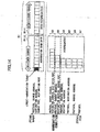
- Fig.4 shows examples of the Flow Record and the data structure definition information.
- a header of four bytes for definition information follows after a header of four bytes common to definition information and Flow Record. And after that, items that form a Flow Record are enumerated.
- SetID In the header of four bytes common to definition information and Flow Record, an ID called SetID is shown using two bytes, and the length of information is indicated by next two bytes. SetID is used for distinguishing among normal definition information, after-mentioned optional definition information, and Flow Record/optional information corresponding to the definition information.
- 0 corresponds to normal definition information
- 1 corresponds to option information
- a value equal to or greater than 256 corresponds to Flow Record/optional information.
- IPFIX 2 corresponds to normal definition information
- 3 corresponds to option information
- a value equal to or greater than 256 corresponds to Flow Record/optional information.
- the header for normal definition information following the header of four bytes common to definition information and Flow Records includes Template ID of two bytes and field count of two bytes.
- the Template ID of two bytes is for indicating which Flow Record for data structure to be defined, and is the same as SetID of corresponding Flow Record.
- the field count indicates the number of items following the Template ID.
- Each item constituting field information represents one piece of information every four bytes.
- the first half two bytes of the four bytes represent an ID of the item, and the latter half two bytes represents the size (the number of bytes) of the item.
- the first item represents that sourceIPv4Address (ID:8) indicating the source address of IPv4 is four bytes
- the next item shows that destinationIPv4Address (ID:12) indicating the destination address of IPv4 is four bytes. Accordingly, the data structure of the Flow Record is defined by the respective items.
- All of the items that form the field information shown in Fig.4 are not necessarily used as the flow generation condition.
- the counter packetetDeltaCount (ID:2), octetDeltaCount (ID:1) shown in Fig.4 )
- all of items other than these are not necessarily used as the flow generation condition.
- IPFIX items that become a flow generation condition are explicitly reported by separate option information.
- NetFlow since there is not such a function, the flow generation condition depends on implementation of the apparatus.
- an item that becomes the flow generation condition is called a Flow Key.
- Fig.5 schematically shows a reporting method using the option information.
- relationship between option data structure definition information and option information is the same as relationship between normal flow data structure definition information and Flow Record.
- the option information is provided with information called scope indicating a range of information.
- scope field count of two bytes is added, and after that, items are enumerated.
- items are enumerated.
- a first number to which the scope field count is added becomes the scope.
- TemplateId the usage is the same as that of the above-mentioned Template ID
- flowKeyIndicator that indicates the flow generation condition is defined.
- the format of the option information is generated according to the option data structure definition information, and concrete values are set as option information. For example, for generating option information corresponding to the Flow Record shown in Fig.4 , a value corresponding to TemplateID becomes 256.
- the flowKeyIndicator is formed as a bit map of 64 bits, and each bit indicates whether a corresponding item can be used as an item of a flow generation condition. That is, as to each of 64 items at the maximum from the top, flowKeyIndicator can indicate whether the item is used as a flow generation condition.
- sourceIPv4Address, destinationIPv4Address, protocolIdentifier, sourceTransportPort, and destinationTransportPort are items of a flow generation condition, since they are located at a first position, a second position, a sixth position, a seventh position, and an eighth position respectively, a first bit, a second bit, a sixth bit, a seventh bit and an eighth bit become 1 respectively in the data of flowKeylndicator.
- the user When using these Flow Record reporting protocols, the user specifies IDs and the sizes of items to be included in a Flow Record that the user wants to send.
- priorities set by the user are provided to conditions that are used as the flow generation condition. By deleting conditions from a low priority condition, a new set of conditions are generated.
- Fig.6 and Fig.7 show definition information having condition priorities and examples of conditions developed and used based on the definition information.
- different values are provided as condition priorities to five items of sourceIPv4Address, destinationIPv4Address, protocolIdentifier, sourceTransportPort and destinationTransportPort. According to these priorities, one set of conditions is generated for each of a case when the number of deletions is 0, a case when the number of deletions is 1, a case when the number of deletions is 2, a case when the number of deletions is 3, and a case when the number of deletions is 4. Thus, five sets of conditions are generated at the maximum.
- priority of each of the items of sourceIPv4Address and destinationIPv4Addreas is 2
- priority of the item of protocolIdentifier is 1
- priority of each of the items of sourceTransportPort and destinationTransportPort is 4.
- one set of conditions is generated when the number of deletions is 0
- two sets of conditions are generated when the number of deletions is 1
- three sets of conditions are generated when the number of deletions is 2
- two sets of conditions are generated when the number of deletions is 3
- one set of conditions is generated when the number of deletions is 4.
- a set of seven conditions is generated at the maximum.
- the Flow Record processing unit 200 may be configured as shown in Fig.8 .
- the Flow Record processing unit 200 shown in Fig.8 is provided with a control unit 206 in addition to the configuration shown in Fig.2 .
- Each of the flow generation function unit 202, the Flow Record number restriction function unit 203 and the flow transmission function unit 204 sends and receives information with the control unit 206,
- Input format of the definition information may be text format of cvs (comma delimited text) shown in Fig.9 or space/tab delimited text, or may be a text using descriptive language such as XML as shown in Fig.10 .
- Fig.10 is an format that is obtained by uniquely adding an element of flowKeyPrecedence indicating condition priorities to the description scheme of configuration Data Model for IPFIX and PSAMP" (http://tools.ietf.org/wg/ipfix/draft-muenz-ipfix-configuration-01.txt (obtained on May 15, 2006)) proposed in IETF.
- the information generated by the flow generation function unit 202 is provided to the Flow Record number restriction function unit 203.
- the Flow Record number restriction function unit 203 before the information generated by the flow generation function unit 202 is transmitted to the flow transmission function unit 204, items that are deleted from flow aggregation conditions are deleted from the Template, or the deleted items are excluded from the bit map of flowKeyIndicator. Since it is necessary to handle all of these as different Templates, each of them is provided with a different Template ID by the flow transmission function unit 204 and is transmitted via the output network interface 205.
- the Flow Record number restriction function unit 203 holds items corresponding to attributes of packets used for generation of Flow Records performed by the flow generation function unit 202 and holds priorities of the items, and the Flow Record number restriction function unit-203 repeats processes for deleting an item of the lowest priority from items for generating Flow Record, so that comparison items are changed in stages.
- Flow Records are sorted based on size relation of data amounts included in the Flow Records.
- Flow Records are sorted based on size relation of the number of messages such as SYN and the like included in the Flow Records.
- the measurement purpose includes a plurality of items, Flow Records are sorted after prioritizing and weighting for the number of pieces of data for each item included in Flow Records. Further, statistical values such as standard deviation and dispersion values of these values can be used as an index for sorting.
- the sorting method can be changed between descending order and ascending order according to the purposes.
- the non-aggregation part B1-1 stores, as non-aggregation Flow Records, the non-aggregation number of higher ranked Flow Records of the sorted Flow Records.
- the aggregation candidate part B1-2 stores, as aggregation candidates, Flow Records of the sorted Flow Records other than the non-aggregation Flow Records.
- the rank becomes lower toward the left side in the figure, and becomes higher toward the right side.
- the buffer B2 stores aggregated Flow Records each of which is obtained by aggregating Flow Records among which four items (aggregation condition) of protocol, source address, destination address and destination port in the flow generation condition agree.
- the buffer B3 stores aggregated Flow Records each of which is obtained by aggregating Flow Records among which four items (aggregation condition) of protocol, source address, destination address and source port in the flow generation condition agree.
- the buffer B4 stores aggregated Flow Records each of which is obtained by aggregating Flow Records among which three items (aggregation condition) of protocol, source address and destination address in the flow generation condition agree.
- the buffer B5 stores aggregated Flow Records each of which is obtained by aggregating Flow Records among which two items (aggregation condition) of protocol and destination address in the flow generation condition agree.
- the buffer B6 stores aggregated Flow Records each of which is obtained by aggregating Flow Records among which two items (aggregation condition) of protocol and source address in the flow generation condition agree.
- the buffer B7 stores aggregated Flow Records each of which is obtained by aggregating Flow Records among which protocol (aggregation condition) in the flow generation condition agrees.
- the aggregation conditions are arranged in the order of buffer B2, buffer B3, buffer B4, buffer B5, buffer B6, and buffer B7 starting from the buffer having the largest number of items forming the condition.
- the number of items forming the condition increases toward the upper side of the figure, and decreases toward the lower side of the figure.
- the Flow Record number restriction function unit 203 sequentially reads Flow Records from the buffer B1 and provides the Flow Records to the flow transmission function unit 204.
- the Flow Record number restriction function unit 203 sorts Flow Records stored in the buffer B1 according to measurement purposes so as to store the higher-ranked Flow Records into the non-aggregation part B1-1, and stores lower-ranked Flow Records in the aggregation candidate part B1-2. Then, Flow Record aggregation processing is executed for the Flow Records (aggregation candidates) stored in the aggregation candidate part B1-2.
- the Flow Records stored in the non-aggregation part B1-1 is sequentially read and provided to the flow transmission function unit 204 without being aggregated.
- sorting of Flow Records stored in the buffer B1 is performed when the number of managed Flow Records exceeds the upper limit value.
- the Flow Records provided from the flow generation function unit 202 may be sorted using an algorithm of insertion sort and the like, so that sorted Flow Records may be stored in the buffer B1.
- Flow Record aggregation processing performed by the Flow Record number restriction function unit 203 is described concretely.
- Fig. 11 shows a procedure of the Flow Record aggregation processing.
- step S1 it is determined whether the number of Flow Records stored and managed in the management buffer unit exceeds the upper limit value. This determination is performed at predetermined intervals or may be performed each time when a Flow Record is input from the flow generation function unit 202.
- the Flow Records stored in the buffer B1 are sorted so that they are divided into aggregation candidates and non-aggregation Flow Records (step S2).
- a lowest ranked Flow Record of the aggregation candidates is extracted as an aggregation target (step S3).
- an initial aggregation condition is set (step 4).
- the initial aggregation condition is a condition having items one less than the flow generation condition. More particularly, the initial aggregation condition is an aggregation condition on the buffer B2 shown in Fig.3 .
- a buffer corresponding to the aggregation condition is set as a search target buffer (step S5). When the aggregation condition on the buffer B2 shown in Fig.3 is set, the buffer B2 becomes the search target buffer.
- step S6 it is determined whether the search target buffer includes an aggregated Flow Record that agrees with the aggregation target in all items of the set aggregation condition.
- the aggregation target is aggregated into the aggregated Flow Record and is stored in a buffer corresponding to the currently set aggregation condition (step S7).
- step S7 When a plurality of aggregated Flow Records agreeing with the aggregation target in all items of the set aggregation condition are found, the aggregation target is aggregated to all of the aggregated Flow Records.
- step S8 When it is determined that there is no aggregated Flow Record that agrees with the aggregation target in all items of the set aggregation condition, it is determined whether the target buffer set in step S5 is the aggregation candidate part B1-2 (step S8). When the target buffer is not the aggregation candidate part B1-2, a buffer (having more items forming a condition) which is one level higher than a current buffer as the search target buffer (step S9), and the process goes to step S6.
- step S10 it is determined whether the currently set aggregation condition is a condition having the smallest number of items for constituting the condition.
- the aggregation condition is not the condition having the smallest number of items, the aggregation condition is changed to a condition having items one less than the current condition (step S11), and the process goes to step S5.
- the aggregation condition is a condition in which the number of items constituting the condition is the smallest, the aggregation target is stored in the buffer of the condition in which the number of items constituting the condition is the smallest (step S12).
- a lowest ranked Flow Record is extracted as an aggregation target from Flow Records stored in the aggregation candidate part B1-2.
- a Flow Record located at leftmost position becomes the aggregation target.
- step S4 as an initial aggregation condition, a condition (aggregation condition of the buffer B2) having items one less than the flow generation condition is set. That is, as the initial aggregation condition, four items of protocol, source address, destination address and destination port of the flow generation condition are set.
- step S5 a buffer corresponding to the set aggregation condition is set as a search target buffer, and the buffer is searched in step S6. At this stage, it is determined whether there exists an aggregated Flow Record that agrees with the aggregation target in all items of the initial aggregation condition in the buffer B2 corresponding to the initial aggregation condition set in step S4.
- Fig.12 shows a state in which the fourth aggregated Flow Record from the left in the buffer B2 agrees with the aggregation target.
- the aggregation target is aggregated to the fourth aggregated Flow Record.
- the aggregation target is deleted from the aggregation candidate part B1-2.
- step S6 it is determined whether the search target buffer is the aggregation candidate part B1-2 in step S8.
- a buffer one level higher than the current buffer is set to be a search target buffer, and then, going to step S6, it is determined whether there is the Flow Record.
- Fig.13 shows a state in which the fifth Flow Record from the left in the aggregation candidate part B1-2 agrees with the aggregation target. In this case, the aggregation target and the fifth Flow Record are aggregated so that the aggregated record is stored in the buffer B2 as aggregated flow information.
- the aggregation target and the fifth Flow Record are deleted from the aggregation candidate part B1-2. There may be a case where there are a plurality of Flow Records that agree with the aggregation target in the search of the higher buffer. In this case, all of the plurality of Flow Records are aggregated to the aggregation target.
- the aggregation condition is a condition (the aggregation condition corresponding to the buffer B7) having the smallest number of items for constituting the condition in step S10.
- the aggregation condition is changed to a condition having items one less than the current condition in step S11. Then, moving to step S5, a buffer corresponding to the changed aggregation condition is set to be a search target buffer.
- the aggregation condition of the buffer B2 is set to be the initial aggregation condition
- the aggregation condition is changed to an aggregation condition of the buffer B3 that is a condition having items one less than the current condition, and the aggregation target buffer is set to be the buffer B3.
- the buffer B3 is searched using the changed aggregation condition.
- Fig.14 shows a state of search for the buffer B3.
- the target buffer is changed in stages using the aggregation condition set in step S4 or step S11.
- aggregation condition is changed in stages.
- aggregation targets can be aggregated without reducing the number of items of aggregation condition more than necessary, and the number of Flow Records decreases along with aggregation.
- processing is performed while moving through a plurality of buffers in the example of the configuration of the buffers shown in Fig.3 and Figs.12-14 and in the example of the algorithm shown in Fig.11 , there is another method for using one buffer by recording ID in each Flow Record in the buffer for indicating and identifying aggregation condition.
- Templates that are transmitted by the flow transmission function unit are basically different, so that Template IDs are different.
- connection type protocol such as TCP in which when a message indicating an end (FIN, RST and the like for TCP) is observed, the flow is regarded to end.
- timeout period is provided for performing data transmission at predetermined intervals. In this case, a flow exceeding the timeout period terminates once, and is counted as different Flow Record having the same values of items used as flow generation/aggregation condition.
- the timeout period there are two kinds of timeout periods that are a non-continuation period (elapsed time after last packet) for connection less type protocol such as UDP and a continuation period (elapsed time from start packet) for connection type protocol such as TCP. Based on these conditions, there is a possibility that flows are separated as different flows even though items used as the flow generation and aggregation condition are the same between the flows.
- the aggregation condition (protocol, source address, destination address and destination port) of the buffer B2 and the aggregation condition (protocol, source address, destination address and source port) of the buffer B3 are the same in the number of items, and are exclusive with each other. Therefore, it is desirable to skip search for the buffer B2 in the search processing in the aggregation condition corresponding to the buffer B3.
- the initial aggregation condition set in step 4 is not limited to the four items of protocol, source address, destination address and source port.
- items of the aggregation condition becomes items constituting a condition (same as the flow generation condition) in which the number of deletions is 0, derived from condition and priority.
- items of the aggregation condition becomes items constituting a condition in which the number of deletions is 1.
- the above-mentioned method is a basic condition reduction method. It can be considered to generate an index for search in order to speed up processing in the condition reduction method. By using the search index, the number of times for search can be decreased.
- a binary tree algorithm For generating the search index, a binary tree algorithm can be used, for example. By using a balanced binary tree, it is possible to perform search at a speed of Log2N. For storing each Flow Record that has information for each of a plurality of items in the binary tree, there are two methods for constructing the binary tree. Generally, a method for constructing the binary tree includes steps of comparing between an element value that has been already stored and an element value to be newly inserted, and determining a storing position based on size relation of them.
- the first constructing method is a method for performing size comparison from an item of higher priority among a plurality of items.
- values are mapped to higher order digits in order to convert the values to one value, so that size comparison is performed using the converted value.
- Fig.15 is a diagram for describing the search index generated by the first constructing method.
- the example shown in Fig.15 is provided with five items of protocolIdentifier (priority is 1), destinationTransportPort (priority is 2), sourceIPv4Address (priority is 3), destinationIPv4Address (priority is 4) and sourceTransportPort (priority is 5) as items of each of Flow Records A-E, Among the Flow Records A-E, priorities are not established. Based on these items, the search index is generated based on the following procedure.
- a flow of B is added to the index. Then, sizes of items are compared between A and B in descending order of item priority starting from the item of highest priority.
- the item of protocolIdentifier of the first priority is the same between flows of A and B, and the item of destinationTransportPort of the second priority is the same between flows of A and B.
- the value "10.0.0.2" of the flow of B is greater than the value "10.0.0.1" of the flow of A.
- B is set to be the root instead of A, and A is set as a leaf of the left side.
- the flow of D is added to the index. Then, sizes of items are compared between B and D in descending order of item priority starting from the item of highest priority.
- a value "17" of the flow of D is greater than the value "6" in the flow of B.
- D is to be placed in the right side. Since C already exists in the right side, sizes of items are compared between C and D in descending order of item priority starting from the item of highest priority.
- the value "192.168.0.1" of the flow of C is greater than the value "10.0.0.1" of the flow of D.
- D is set to be a leaf of the left side of C.
- E is added to the index. Then, sizes of items are compared between B and E in descending order of item priority starting from the item of highest priority.
- a value "6" of the flow of B is greater than the value "1" in the flow of E.
- E is to be placed in the left side. Since A already exists in the left side, sizes of items are compared between A and E in descending order of item priority starting from the item of highest priority.
- the value "6" of the flow of A is greater than the value "1" , of the flow of E.
- E is set to be a leaf of the left side of A.
- the second constructing method is a method in which generation of a binary tree starts from the highest priority item, and, as to each of items of priority lower than the highest priority, a leaf of an higher priority item is set to be a root of lower priority item.
- Fig.16 is a diagram for explaining the search index generated by the second construction method. Also in the example shown in Fig.16 , as the items for the Flow Records A-E, five items having priorities similar to those of the example shown in Fig.15 are provided, and the search index is generated in the following procedure based on these items.
- An element (value : 6) of protocolIdentifier of the first priority is added as a pointer that is a root of the tree.
- the pointer of the root of the tree indicates the element.
- the element has a pointer specifying the second priority.
- the element (value ; 192.168.0.1) of destinationTransportPort of the second priority the element (value : 10.0.0.1) of sourceIPv4Addres of the third priority
- the element (value : 80) of destinationIPv4Address of the fourth priority and the element (value : 23456) of sourceTransportPort of the fifth priority are added, and an element indicating an element number (value : A) is added under the tree.
- the tree structure is simple, the tree does not become deep, and a balance (balanced tree) can be generated.
- a balance balanced tree
- the second construction method although the tree becomes deep, once the tree structure is generated, a part of leafs can be aggregated even though a condition is reduced unless there are overlapping priorities. Thus, it is not necessary to regenerate the tree structure again.
- it is possible to change handling method of information for each item for example, it is possible to exclude a particular port.
- the second construction method cannot be applied when priorities overlap.
- the flow generation function unit determines size relation among the Flow Records by repeating size comparison for each item held by the Flow Records based on priorities of the items input from the outside, and holds the result as the search index so as to generate Flow Records by referring to the search index. Accordingly, the number of times for comparing conditions (each being a combination of items) for generating Flow Records can be reduced. As a result, efficiency of processing can be improved.
- the Flow Record number restriction function unit determines size relation among the Flow Records by repeating size comparison for each item held by the Flow Records based on priorities of the items input from the outside, and holds the result as the search index so as to aggregate Flow Records by referring to the search index. Accordingly, the number of times for comparing conditions (each being a combination of items) for aggregating Flow Records can be reduced. As a result, efficiency of processing can be improved.
- the first construction method as a method for suppressing decrease of efficiency at a minimum when regenerating the tree structure for each condition, there is a method for having the number of aggregate candidates of a past same condition and having the number of held Flow Records for each condition.
- the Flow Record number restriction function unit recodes the number of aggregation candidates and the number of aggregation results which are calculated using the upper limit value and the non-aggregation number that are already held, and records histories of the number of flows for each item of the aggregation condition when performing flow Record restriction.
- the Flow Record number restriction function unit estimates the number of initial items used for generating the search index based on the recorded information so as to reduce the number of times for generating the search index.
- the upper limit value is a number (provided from the outside, or determined internally based on the capacity of the management buffer) of Flow Records to be finally provided to the flow transmission function unit by the Flow Record number restriction function unit.
- the non-aggregation number is a number (provided from the outside) of Flow Records, which are not aggregated, located at higher positions after sorting.
- the number of aggregation candidates is a value obtained by subtracting the non-aggregation number from the total number of Flow Records generated by the flow generation function unit.
- the number of aggregation results is a value of results of aggregation, that is, it is a value obtains by subtracting the non-aggregation number from the upper limit value.
- the Flow Record number restriction function unit holds the number of aggregation candidates that is obtained by subtracting the non-aggregation number from the total number of the generated Flow Records, the number of aggregation results obtained by subtracting the non-aggregation number from the upper limit value, the number of Flow Records for each item of information (Information Element) in the condition (Flow Key) used for aggregation.
- Fig.17 shows an example of information held by the Flow Record number restriction function unit.
- Fig.17 information of past five times are recorded for the number of aggregation candidates, the number of aggregation results, and each item such as protocolIdentifier (priority is 1), destinationTransportPort (priority is 2), sourceIPv4Address (priority is 3), destinationIPv4Address (priority is 4), and sourceTransportPort (priority is 5).
- the number of aggregation candidates is 120034, and the number of aggregation results is 20000.
- the number of flows of the results aggregated by using only protocolIdentifier is 4 in which protocolIdentifier is an aggregation condition including the item of the first priority
- the number of flows of the results aggregated by using an aggregation condition condition of number of deletions : 3 in Fig.6 ) including items up to the second priority
- the number of flows of the results aggregated by using an aggregation condition condition of number of deletions : 2 in Fig.6
- the number of flows of the results aggregated by using an aggregation condition condition of number of deletions : 1 in Fig.6
- the fourth priority is 1233, and the number of flows of the results aggregated by using an
- the aggregation in which the number of flow is 0 is regarded as unnecessary aggregation as a result. That is, in the first most recent aggregation, a condition including items up to the fifth priority is omitted, and generation of the index is started from the condition including items up to the fourth priority. Accordingly, the number of times of processing is reduced so that processing speed increases.
- the Flow Record number restriction function unit determines a case in which aggregation can be omitted based on past records.
- the number of flows is 0 when using a condition including items up to the fifth priority.
- the numbers of aggregation candidates are 120034, 93898, and 108270 respectively for the first, third and fifth aggregation.
- the index can be made from the condition including items up to the fourth priority (that is, a combination of items of protocolIdentifier, protocolIdentifier, destinationTransportPort, and destinationIPv4Address). In this case, since it becomes unnecessary to generate the index based on a condition including items up to the fifth priority, processing speed of the whole system can be increased.
- FIG.18 shows an example for aggregating ports.
- each of A and B is a Flow Record that is generated by a condition (flow generation condition) of five items of protocol, source address, destination address, source port and destination port.
- C is aggregated a Flow Record obtained by aggregating Flow Records A and B using items of the flow generation condition as an aggregation condition.
- source port is deleted from items constituting the aggregation condition.
- SA indicates source address
- DA indicates destination address
- SAMask indicates destination address
- DAMask are netmasks
- SP indicates source port
- DP indicates destination port
- Packets indicates the number of packets
- octets indicates the number of bytes
- First is a start time of flow
- “Last” is an end time of flow.
- the value of source port "SP" is set to be “0"
- the number of packets "Packets” and the number of bytes “octets” are set to be values obtained by adding corresponding values of Flow Records A and B, respectively.
- each of the start time “First” and the end time “Last” is set to be in a range of union of times corresponding to the Flow Records A and B.
- a start time “First” and an end time “Last” of the Flow Record A are set to be “134598098987” and “134598100384" respectively, and a start time “First” and an end time “Last” of the Flow Record B are set to be “134596098222” and “134598100001” respectively.
- a start time “First” and an end time “Last” of the Flow Record C are set to be "134598098222" and "134598100384" respectively.
- the aggregated Flow Record C can be obtained by aggregating the source port "SP", the number of packets "Packets", the start time "First", and the end time "Last".
- source port is set to be 0 in the aggregated Flow Record C.
- a source port number where the data amount is the greatest may be set.
- information of a head packet of a flow may be used as a representative value, and information indicating that aggregation has been performed may be added.
- Two schemes can be applied when deleting an item of aggregation condition. One scheme is to delete the item forming corresponding field information from the Template, and another scheme is to delete the item from the Flow Key without deleting the item from the Template. As to the former scheme, since the deleted item is not transmitted, any value may be set internally. In the latter case, a representative value of the deleted item is transmitted. According to the specification of IPFIX protocol, it is recommended to use a value observed first for an item that is not used as the Flow Key.
- Fig.19 shows an example for aggregating addresses.
- each of A and B is a Flow Record that is generated based on a condition (flow generation condition) of five items of protocol, source address, destination address, source port and destination port.
- C is an aggregated Flow Record obtained by aggregating the Flow Records A and B using three items of protocol, source address and destination address in the flow generation condition as an aggregation condition.
- the value of source port "SP" is set to be "0"
- each of the number of packets "Packets” and the number of bytes “octets” is one obtained by adding corresponding values of Flow Records A and B
- each of the start time "First” and the end time “Last” is set to be in a range of union of corresponding times of the Flow Records A and B.
- Each address is set to be a new value obtained as a product set of values of corresponding address of the Flow Records A and B.
- a new destination address "192.168.0.0" is obtained as a product set of the destination address '192.168.0.2” of the Flow Record A and the destination address "192.168.0.254" of the Flow Record B.
- the netmask "SAMask” is also changed to "24".
- the total number of possible values of items forming the aggregation condition in a state in which the number of deletions is largest becomes a minimum value as the upper limit value for ensuring that the number can be restricted to be equal to or less than a predetermined number.
- the Flow Record number restriction function unit aggregates a part (aggregation candidates) of the stored Flow Records.
- the number of Flow Records provided to the flow transmission function unit per a predetermined time can be restricted to be equal to or less than a predetermined number. Therefore, the number of Flow Records that the flow transmission function unit transmits over the measurement network per a predetermined time is also limited to equal to or less than a predetermined number.
- Flow Records that include important information in measurement of traffic are excluded from targets of aggregation, and unimportant Flow Records are aggregated.
- Flow Records that characterize traffic in a measurement purpose are maintained.
- Flow Record restriction apparatus (node) of the present embodiment described above is an example of the present invention, and variations and modifications may be made for the configuration and the operation without departing from the scope of the present invention.
- each of the flow generation function unit, the Flow Record number restriction function unit and the flow transmission function unit can be realized by executing a program stored in a storage apparatus by a control apparatus that forms a computer system.
- the program may be provided via a disk type recording medium such as a CD-ROM and a DVD, and the program may be provided by downloading via the Internet.
- Items for the flow generation condition and the aggregation condition may include items other than these or may include none of these items as long as each of the items include information based on header information.
- the information based on header information includes information determined from header information, even when it is not included in a header itself. As an example, routing information is included in the information based on the header information.
- the header information is not limited to the network layer and the transport layer, and includes protocols upper and lower of these.
- the number of items of the flow generation condition and the aggregation condition can be properly set within a range in which generation and aggregation of flows are available.
Landscapes
- Engineering & Computer Science (AREA)
- Computer Networks & Wireless Communication (AREA)
- Signal Processing (AREA)
- Data Exchanges In Wide-Area Networks (AREA)
Applications Claiming Priority (3)
| Application Number | Priority Date | Filing Date | Title |
|---|---|---|---|
| JP2006314299 | 2006-11-21 | ||
| JP2007199499A JP4658098B2 (ja) | 2006-11-21 | 2007-07-31 | フロー情報制限装置および方法 |
| PCT/JP2007/072456 WO2008062787A1 (fr) | 2006-11-21 | 2007-11-20 | Appareil et procédé de restriction d'informations de flux |
Publications (3)
| Publication Number | Publication Date |
|---|---|
| EP2086183A1 EP2086183A1 (en) | 2009-08-05 |
| EP2086183A4 EP2086183A4 (en) | 2010-01-06 |
| EP2086183B1 true EP2086183B1 (en) | 2013-01-30 |
Family
ID=39429717
Family Applications (1)
| Application Number | Title | Priority Date | Filing Date |
|---|---|---|---|
| EP07832186A Not-in-force EP2086183B1 (en) | 2006-11-21 | 2007-11-20 | Flow information restricting apparatus and method |
Country Status (6)
| Country | Link |
|---|---|
| US (1) | US8239565B2 (ja) |
| EP (1) | EP2086183B1 (ja) |
| JP (1) | JP4658098B2 (ja) |
| KR (1) | KR100997182B1 (ja) |
| CN (1) | CN101536437B (ja) |
| WO (1) | WO2008062787A1 (ja) |
Families Citing this family (16)
| Publication number | Priority date | Publication date | Assignee | Title |
|---|---|---|---|---|
| US9026674B1 (en) * | 2010-03-22 | 2015-05-05 | Satish K Kanna | System and method for accurately displaying communications traffic information |
| CN101563908B (zh) * | 2006-12-19 | 2013-01-09 | 国际商业机器公司 | 分析网络流的装置和方法 |
| US9258217B2 (en) * | 2008-12-16 | 2016-02-09 | At&T Intellectual Property I, L.P. | Systems and methods for rule-based anomaly detection on IP network flow |
| US8125920B2 (en) * | 2009-03-04 | 2012-02-28 | Cisco Technology, Inc. | System and method for exporting structured data in a network environment |
| US8443434B1 (en) * | 2009-10-06 | 2013-05-14 | Palo Alto Networks, Inc. | High availability security device |
| US8724487B1 (en) | 2010-02-15 | 2014-05-13 | Cisco Technology, Inc. | System and method for synchronized reporting in a network environment |
| CN102075412B (zh) * | 2010-10-22 | 2013-06-19 | 北京神州绿盟信息安全科技股份有限公司 | 一种网络数据传输速率控制设备及方法 |
| KR101433420B1 (ko) * | 2010-11-16 | 2014-08-28 | 한국전자통신연구원 | 플로우 기반 데이터 병렬 처리 장치 및 방법 |
| EP2530874B1 (en) * | 2011-06-03 | 2020-04-29 | AirMagnet, Inc. | Method and apparatus for detecting network attacks using a flow based technique |
| US9674207B2 (en) * | 2014-07-23 | 2017-06-06 | Cisco Technology, Inc. | Hierarchical attack detection in a network |
| US10536357B2 (en) | 2015-06-05 | 2020-01-14 | Cisco Technology, Inc. | Late data detection in data center |
| US10142353B2 (en) | 2015-06-05 | 2018-11-27 | Cisco Technology, Inc. | System for monitoring and managing datacenters |
| US10674394B2 (en) * | 2017-10-27 | 2020-06-02 | Futurewei Technologies, Inc. | Method and apparatus for reducing network latency |
| US10999167B2 (en) * | 2018-04-13 | 2021-05-04 | At&T Intellectual Property I, L.P. | Varying data flow aggregation period relative to data value |
| US11546185B2 (en) * | 2020-04-27 | 2023-01-03 | Hewlett Packard Enterprise Development Lp | Multicast route summarization |
| WO2023105647A1 (ja) * | 2021-12-07 | 2023-06-15 | 日本電信電話株式会社 | フロー情報収集システム、フロー情報収集方法、および、フロー情報収集プログラム |
Family Cites Families (19)
| Publication number | Priority date | Publication date | Assignee | Title |
|---|---|---|---|---|
| US7466703B1 (en) * | 1998-05-01 | 2008-12-16 | Alcatel-Lucent Usa Inc. | Scalable high speed router apparatus |
| US6570875B1 (en) * | 1998-10-13 | 2003-05-27 | Intel Corporation | Automatic filtering and creation of virtual LANs among a plurality of switch ports |
| US6671258B1 (en) * | 2000-02-01 | 2003-12-30 | Alcatel Canada Inc. | Dynamic buffering system having integrated random early detection |
| JP3994614B2 (ja) * | 2000-03-13 | 2007-10-24 | 株式会社日立製作所 | パケット交換機、ネットワーク監視システム及びネットワーク監視方法 |
| US6836466B1 (en) * | 2000-05-26 | 2004-12-28 | Telcordia Technologies, Inc. | Method and system for measuring IP performance metrics |
| AU2001281150A1 (en) * | 2000-08-07 | 2002-02-18 | Xacct Technologies Limited | System, method and computer program product for processing network accounting information |
| US20020035698A1 (en) | 2000-09-08 | 2002-03-21 | The Regents Of The University Of Michigan | Method and system for protecting publicly accessible network computer services from undesirable network traffic in real-time |
| US7039013B2 (en) * | 2001-12-31 | 2006-05-02 | Nokia Corporation | Packet flow control method and device |
| JP4234933B2 (ja) | 2002-02-15 | 2009-03-04 | 日本電信電話株式会社 | トラヒックデータ生成装置 |
| US7286482B2 (en) * | 2002-11-29 | 2007-10-23 | Alcatel Lucent | Decentralized SLS monitoring in a differentiated service environment |
| US7701863B2 (en) * | 2002-12-12 | 2010-04-20 | Alcatel Lucent | Decentralized SLS monitoring for throughput in a differentiated service environment |
| JP2005010756A (ja) | 2003-05-23 | 2005-01-13 | Olympus Corp | 光学系 |
| US7453806B2 (en) * | 2003-06-26 | 2008-11-18 | International Business Machines Corporation | Dynamic data packet flow control for packet switching node |
| US7385924B1 (en) * | 2003-09-30 | 2008-06-10 | Packeteer, Inc. | Enhanced flow data records including traffic type data |
| JP2006050442A (ja) * | 2004-08-06 | 2006-02-16 | Nippon Telegr & Teleph Corp <Ntt> | トラヒック監視方法及びシステム |
| US7515591B1 (en) * | 2004-08-31 | 2009-04-07 | Adtran, Inc. | Primary channel bank-resident mechanism for scheduling downstream data transmissions to ports of multiple channel banks |
| JP2005210756A (ja) | 2005-04-08 | 2005-08-04 | Hitachi Ltd | ネットワーク監視方法 |
| US7738375B1 (en) * | 2005-08-19 | 2010-06-15 | Juniper Networks, Inc. | Shared shaping of network traffic |
| US20070140282A1 (en) * | 2005-12-21 | 2007-06-21 | Sridhar Lakshmanamurthy | Managing on-chip queues in switched fabric networks |
-
2007
- 2007-07-31 JP JP2007199499A patent/JP4658098B2/ja active Active
- 2007-11-20 WO PCT/JP2007/072456 patent/WO2008062787A1/ja active Application Filing
- 2007-11-20 KR KR1020097009813A patent/KR100997182B1/ko active IP Right Grant
- 2007-11-20 EP EP07832186A patent/EP2086183B1/en not_active Not-in-force
- 2007-11-20 US US12/514,883 patent/US8239565B2/en active Active
- 2007-11-20 CN CN2007800423057A patent/CN101536437B/zh not_active Expired - Fee Related
Also Published As
| Publication number | Publication date |
|---|---|
| KR100997182B1 (ko) | 2010-11-29 |
| EP2086183A4 (en) | 2010-01-06 |
| CN101536437B (zh) | 2012-02-01 |
| JP4658098B2 (ja) | 2011-03-23 |
| KR20090079945A (ko) | 2009-07-22 |
| CN101536437A (zh) | 2009-09-16 |
| JP2008154204A (ja) | 2008-07-03 |
| WO2008062787A1 (fr) | 2008-05-29 |
| US20100070647A1 (en) | 2010-03-18 |
| EP2086183A1 (en) | 2009-08-05 |
| US8239565B2 (en) | 2012-08-07 |
Similar Documents
| Publication | Publication Date | Title |
|---|---|---|
| EP2086183B1 (en) | Flow information restricting apparatus and method | |
| US7580356B1 (en) | Method and system for dynamically capturing flow traffic data | |
| US7639613B1 (en) | Adaptive, flow-based network traffic measurement and monitoring system | |
| US7440409B2 (en) | Network traffic monitoring system and monitoring method | |
| CN1953392B (zh) | 异常通信量的检测方法和数据包中继装置 | |
| JP4759389B2 (ja) | パケット通信装置 | |
| US7742406B1 (en) | Coordinated environment for classification and control of network traffic | |
| US8358592B2 (en) | Network controller and control method with flow analysis and control function | |
| US8295198B2 (en) | Method for configuring ACLs on network device based on flow information | |
| US7623466B2 (en) | Symmetric connection detection | |
| JP4774357B2 (ja) | 統計情報収集システム及び統計情報収集装置 | |
| US8130767B2 (en) | Method and apparatus for aggregating network traffic flows | |
| Tammaro et al. | Exploiting packet‐sampling measurements for traffic characterization and classification | |
| CN101800707B (zh) | 建立流转发表项的方法及数据通信设备 | |
| US20070201359A1 (en) | Traffic information aggregating apparatus | |
| JP5017440B2 (ja) | ネットワーク制御装置およびその制御方法 | |
| Lu et al. | A novel path‐based approach for single‐packet IP traceback | |
| CN1767496B (zh) | 智能选择性的基于流的数据路径结构 | |
| Cho et al. | Aguri: An aggregation-based traffic profiler | |
| CN102480503B (zh) | P2p流量识别方法和装置 | |
| Pries et al. | On traffic characteristics of a broadband wireless internet access | |
| Cheng et al. | Identifying BT-like P2P traffic by the discreteness of remote hosts | |
| Bellaïche et al. | SYN flooding attack detection by TCP handshake anomalies | |
| JP4489714B2 (ja) | パケット集約方法、装置、およびプログラム | |
| Lan et al. | Passive overall packet loss estimation at the border of an ISP |
Legal Events
| Date | Code | Title | Description |
|---|---|---|---|
| PUAI | Public reference made under article 153(3) epc to a published international application that has entered the european phase |
Free format text: ORIGINAL CODE: 0009012 |
|
| 17P | Request for examination filed |
Effective date: 20090514 |
|
| AK | Designated contracting states |
Kind code of ref document: A1 Designated state(s): AT BE BG CH CY CZ DE DK EE ES FI FR GB GR HU IE IS IT LI LT LU LV MC MT NL PL PT RO SE SI SK TR |
|
| A4 | Supplementary search report drawn up and despatched |
Effective date: 20091207 |
|
| DAX | Request for extension of the european patent (deleted) | ||
| 17Q | First examination report despatched |
Effective date: 20100719 |
|
| GRAP | Despatch of communication of intention to grant a patent |
Free format text: ORIGINAL CODE: EPIDOSNIGR1 |
|
| GRAS | Grant fee paid |
Free format text: ORIGINAL CODE: EPIDOSNIGR3 |
|
| REG | Reference to a national code |
Ref country code: DE Ref legal event code: R079 Ref document number: 602007028330 Country of ref document: DE Free format text: PREVIOUS MAIN CLASS: H04L0012560000 Ipc: H04L0012801000 |
|
| GRAA | (expected) grant |
Free format text: ORIGINAL CODE: 0009210 |
|
| RIN1 | Information on inventor provided before grant (corrected) |
Inventor name: KATAYAMA, MASARU Inventor name: IRINO, HITOSHI |
|
| RIC1 | Information provided on ipc code assigned before grant |
Ipc: H04L 12/801 20130101AFI20121220BHEP |
|
| AK | Designated contracting states |
Kind code of ref document: B1 Designated state(s): AT BE BG CH CY CZ DE DK EE ES FI FR GB GR HU IE IS IT LI LT LU LV MC MT NL PL PT RO SE SI SK TR |
|
| REG | Reference to a national code |
Ref country code: GB Ref legal event code: FG4D |
|
| REG | Reference to a national code |
Ref country code: CH Ref legal event code: EP |
|
| REG | Reference to a national code |
Ref country code: AT Ref legal event code: REF Ref document number: 595884 Country of ref document: AT Kind code of ref document: T Effective date: 20130215 Ref country code: CH Ref legal event code: EP |
|
| REG | Reference to a national code |
Ref country code: IE Ref legal event code: FG4D |
|
| REG | Reference to a national code |
Ref country code: DE Ref legal event code: R096 Ref document number: 602007028330 Country of ref document: DE Effective date: 20130328 |
|
| REG | Reference to a national code |
Ref country code: AT Ref legal event code: MK05 Ref document number: 595884 Country of ref document: AT Kind code of ref document: T Effective date: 20130130 |
|
| REG | Reference to a national code |
Ref country code: LT Ref legal event code: MG4D |
|
| REG | Reference to a national code |
Ref country code: NL Ref legal event code: VDEP Effective date: 20130130 |
|
| PG25 | Lapsed in a contracting state [announced via postgrant information from national office to epo] |
Ref country code: ES Free format text: LAPSE BECAUSE OF FAILURE TO SUBMIT A TRANSLATION OF THE DESCRIPTION OR TO PAY THE FEE WITHIN THE PRESCRIBED TIME-LIMIT Effective date: 20130511 Ref country code: IS Free format text: LAPSE BECAUSE OF FAILURE TO SUBMIT A TRANSLATION OF THE DESCRIPTION OR TO PAY THE FEE WITHIN THE PRESCRIBED TIME-LIMIT Effective date: 20130530 Ref country code: BE Free format text: LAPSE BECAUSE OF FAILURE TO SUBMIT A TRANSLATION OF THE DESCRIPTION OR TO PAY THE FEE WITHIN THE PRESCRIBED TIME-LIMIT Effective date: 20130130 Ref country code: SE Free format text: LAPSE BECAUSE OF FAILURE TO SUBMIT A TRANSLATION OF THE DESCRIPTION OR TO PAY THE FEE WITHIN THE PRESCRIBED TIME-LIMIT Effective date: 20130130 Ref country code: LT Free format text: LAPSE BECAUSE OF FAILURE TO SUBMIT A TRANSLATION OF THE DESCRIPTION OR TO PAY THE FEE WITHIN THE PRESCRIBED TIME-LIMIT Effective date: 20130130 Ref country code: BG Free format text: LAPSE BECAUSE OF FAILURE TO SUBMIT A TRANSLATION OF THE DESCRIPTION OR TO PAY THE FEE WITHIN THE PRESCRIBED TIME-LIMIT Effective date: 20130430 Ref country code: AT Free format text: LAPSE BECAUSE OF FAILURE TO SUBMIT A TRANSLATION OF THE DESCRIPTION OR TO PAY THE FEE WITHIN THE PRESCRIBED TIME-LIMIT Effective date: 20130130 |
|
| PG25 | Lapsed in a contracting state [announced via postgrant information from national office to epo] |
Ref country code: SI Free format text: LAPSE BECAUSE OF FAILURE TO SUBMIT A TRANSLATION OF THE DESCRIPTION OR TO PAY THE FEE WITHIN THE PRESCRIBED TIME-LIMIT Effective date: 20130130 Ref country code: NL Free format text: LAPSE BECAUSE OF FAILURE TO SUBMIT A TRANSLATION OF THE DESCRIPTION OR TO PAY THE FEE WITHIN THE PRESCRIBED TIME-LIMIT Effective date: 20130130 Ref country code: PT Free format text: LAPSE BECAUSE OF FAILURE TO SUBMIT A TRANSLATION OF THE DESCRIPTION OR TO PAY THE FEE WITHIN THE PRESCRIBED TIME-LIMIT Effective date: 20130530 Ref country code: LV Free format text: LAPSE BECAUSE OF FAILURE TO SUBMIT A TRANSLATION OF THE DESCRIPTION OR TO PAY THE FEE WITHIN THE PRESCRIBED TIME-LIMIT Effective date: 20130130 Ref country code: PL Free format text: LAPSE BECAUSE OF FAILURE TO SUBMIT A TRANSLATION OF THE DESCRIPTION OR TO PAY THE FEE WITHIN THE PRESCRIBED TIME-LIMIT Effective date: 20130130 Ref country code: GR Free format text: LAPSE BECAUSE OF FAILURE TO SUBMIT A TRANSLATION OF THE DESCRIPTION OR TO PAY THE FEE WITHIN THE PRESCRIBED TIME-LIMIT Effective date: 20130501 Ref country code: FI Free format text: LAPSE BECAUSE OF FAILURE TO SUBMIT A TRANSLATION OF THE DESCRIPTION OR TO PAY THE FEE WITHIN THE PRESCRIBED TIME-LIMIT Effective date: 20130130 |
|
| PG25 | Lapsed in a contracting state [announced via postgrant information from national office to epo] |
Ref country code: RO Free format text: LAPSE BECAUSE OF FAILURE TO SUBMIT A TRANSLATION OF THE DESCRIPTION OR TO PAY THE FEE WITHIN THE PRESCRIBED TIME-LIMIT Effective date: 20130130 Ref country code: SK Free format text: LAPSE BECAUSE OF FAILURE TO SUBMIT A TRANSLATION OF THE DESCRIPTION OR TO PAY THE FEE WITHIN THE PRESCRIBED TIME-LIMIT Effective date: 20130130 Ref country code: EE Free format text: LAPSE BECAUSE OF FAILURE TO SUBMIT A TRANSLATION OF THE DESCRIPTION OR TO PAY THE FEE WITHIN THE PRESCRIBED TIME-LIMIT Effective date: 20130130 Ref country code: CZ Free format text: LAPSE BECAUSE OF FAILURE TO SUBMIT A TRANSLATION OF THE DESCRIPTION OR TO PAY THE FEE WITHIN THE PRESCRIBED TIME-LIMIT Effective date: 20130130 Ref country code: DK Free format text: LAPSE BECAUSE OF FAILURE TO SUBMIT A TRANSLATION OF THE DESCRIPTION OR TO PAY THE FEE WITHIN THE PRESCRIBED TIME-LIMIT Effective date: 20130130 |
|
| PG25 | Lapsed in a contracting state [announced via postgrant information from national office to epo] |
Ref country code: CY Free format text: LAPSE BECAUSE OF FAILURE TO SUBMIT A TRANSLATION OF THE DESCRIPTION OR TO PAY THE FEE WITHIN THE PRESCRIBED TIME-LIMIT Effective date: 20130130 |
|
| PLBE | No opposition filed within time limit |
Free format text: ORIGINAL CODE: 0009261 |
|
| STAA | Information on the status of an ep patent application or granted ep patent |
Free format text: STATUS: NO OPPOSITION FILED WITHIN TIME LIMIT |
|
| PG25 | Lapsed in a contracting state [announced via postgrant information from national office to epo] |
Ref country code: IT Free format text: LAPSE BECAUSE OF FAILURE TO SUBMIT A TRANSLATION OF THE DESCRIPTION OR TO PAY THE FEE WITHIN THE PRESCRIBED TIME-LIMIT Effective date: 20130130 |
|
| 26N | No opposition filed |
Effective date: 20131031 |
|
| REG | Reference to a national code |
Ref country code: DE Ref legal event code: R097 Ref document number: 602007028330 Country of ref document: DE Effective date: 20131031 |
|
| REG | Reference to a national code |
Ref country code: CH Ref legal event code: PL |
|
| PG25 | Lapsed in a contracting state [announced via postgrant information from national office to epo] |
Ref country code: LI Free format text: LAPSE BECAUSE OF NON-PAYMENT OF DUE FEES Effective date: 20131130 Ref country code: MC Free format text: LAPSE BECAUSE OF FAILURE TO SUBMIT A TRANSLATION OF THE DESCRIPTION OR TO PAY THE FEE WITHIN THE PRESCRIBED TIME-LIMIT Effective date: 20130130 Ref country code: CH Free format text: LAPSE BECAUSE OF NON-PAYMENT OF DUE FEES Effective date: 20131130 |
|
| REG | Reference to a national code |
Ref country code: IE Ref legal event code: MM4A |
|
| PG25 | Lapsed in a contracting state [announced via postgrant information from national office to epo] |
Ref country code: IE Free format text: LAPSE BECAUSE OF NON-PAYMENT OF DUE FEES Effective date: 20131120 |
|
| PG25 | Lapsed in a contracting state [announced via postgrant information from national office to epo] |
Ref country code: TR Free format text: LAPSE BECAUSE OF FAILURE TO SUBMIT A TRANSLATION OF THE DESCRIPTION OR TO PAY THE FEE WITHIN THE PRESCRIBED TIME-LIMIT Effective date: 20130130 |
|
| PG25 | Lapsed in a contracting state [announced via postgrant information from national office to epo] |
Ref country code: LU Free format text: LAPSE BECAUSE OF NON-PAYMENT OF DUE FEES Effective date: 20131120 Ref country code: HU Free format text: LAPSE BECAUSE OF FAILURE TO SUBMIT A TRANSLATION OF THE DESCRIPTION OR TO PAY THE FEE WITHIN THE PRESCRIBED TIME-LIMIT; INVALID AB INITIO Effective date: 20071120 |
|
| PG25 | Lapsed in a contracting state [announced via postgrant information from national office to epo] |
Ref country code: MT Free format text: LAPSE BECAUSE OF FAILURE TO SUBMIT A TRANSLATION OF THE DESCRIPTION OR TO PAY THE FEE WITHIN THE PRESCRIBED TIME-LIMIT Effective date: 20130130 |
|
| REG | Reference to a national code |
Ref country code: FR Ref legal event code: PLFP Year of fee payment: 9 |
|
| REG | Reference to a national code |
Ref country code: FR Ref legal event code: PLFP Year of fee payment: 10 |
|
| REG | Reference to a national code |
Ref country code: FR Ref legal event code: PLFP Year of fee payment: 11 |
|
| REG | Reference to a national code |
Ref country code: DE Ref legal event code: R079 Ref document number: 602007028330 Country of ref document: DE Free format text: PREVIOUS MAIN CLASS: H04L0012801000 Ipc: H04L0047100000 |
|
| PGFP | Annual fee paid to national office [announced via postgrant information from national office to epo] |
Ref country code: DE Payment date: 20211118 Year of fee payment: 15 Ref country code: GB Payment date: 20211119 Year of fee payment: 15 Ref country code: FR Payment date: 20211122 Year of fee payment: 15 |
|
| REG | Reference to a national code |
Ref country code: DE Ref legal event code: R119 Ref document number: 602007028330 Country of ref document: DE |
|
| GBPC | Gb: european patent ceased through non-payment of renewal fee |
Effective date: 20221120 |
|
| PG25 | Lapsed in a contracting state [announced via postgrant information from national office to epo] |
Ref country code: GB Free format text: LAPSE BECAUSE OF NON-PAYMENT OF DUE FEES Effective date: 20221120 Ref country code: DE Free format text: LAPSE BECAUSE OF NON-PAYMENT OF DUE FEES Effective date: 20230601 |
|
| PG25 | Lapsed in a contracting state [announced via postgrant information from national office to epo] |
Ref country code: FR Free format text: LAPSE BECAUSE OF NON-PAYMENT OF DUE FEES Effective date: 20221130 |