EP1944248A1 - Capsule, means for penetrating the bottom of a capsule and device for preparing a drink - Google Patents
Capsule, means for penetrating the bottom of a capsule and device for preparing a drink Download PDFInfo
- Publication number
- EP1944248A1 EP1944248A1 EP20070100520 EP07100520A EP1944248A1 EP 1944248 A1 EP1944248 A1 EP 1944248A1 EP 20070100520 EP20070100520 EP 20070100520 EP 07100520 A EP07100520 A EP 07100520A EP 1944248 A1 EP1944248 A1 EP 1944248A1
- Authority
- EP
- European Patent Office
- Prior art keywords
- capsule
- wall portion
- penetration
- lid
- zone
- Prior art date
- Legal status (The legal status is an assumption and is not a legal conclusion. Google has not performed a legal analysis and makes no representation as to the accuracy of the status listed.)
- Granted
Links
- 239000002775 capsule Substances 0.000 title claims abstract description 107
- 230000000149 penetrating effect Effects 0.000 title claims description 6
- 239000000126 substance Substances 0.000 claims abstract description 10
- 238000002360 preparation method Methods 0.000 claims abstract description 8
- 235000013361 beverage Nutrition 0.000 claims abstract description 6
- 230000035515 penetration Effects 0.000 claims description 53
- 230000006835 compression Effects 0.000 claims description 8
- 238000007906 compression Methods 0.000 claims description 8
- 239000007788 liquid Substances 0.000 claims description 5
- 238000005520 cutting process Methods 0.000 claims description 3
- 239000003795 chemical substances by application Substances 0.000 claims 3
- 239000011888 foil Substances 0.000 claims 1
- 230000002787 reinforcement Effects 0.000 abstract 1
- 239000000463 material Substances 0.000 description 6
- 230000000694 effects Effects 0.000 description 5
- 238000000605 extraction Methods 0.000 description 5
- XLYOFNOQVPJJNP-UHFFFAOYSA-N water Substances O XLYOFNOQVPJJNP-UHFFFAOYSA-N 0.000 description 5
- 238000000034 method Methods 0.000 description 4
- 239000000843 powder Substances 0.000 description 4
- 230000008569 process Effects 0.000 description 4
- 230000008901 benefit Effects 0.000 description 3
- 238000001914 filtration Methods 0.000 description 3
- 240000007594 Oryza sativa Species 0.000 description 2
- 235000007164 Oryza sativa Nutrition 0.000 description 2
- 238000001746 injection moulding Methods 0.000 description 2
- 238000004519 manufacturing process Methods 0.000 description 2
- 230000007246 mechanism Effects 0.000 description 2
- 230000002093 peripheral effect Effects 0.000 description 2
- 239000004033 plastic Substances 0.000 description 2
- 235000009566 rice Nutrition 0.000 description 2
- 239000004743 Polypropylene Substances 0.000 description 1
- 244000269722 Thea sinensis Species 0.000 description 1
- 238000005056 compaction Methods 0.000 description 1
- 235000013399 edible fruits Nutrition 0.000 description 1
- 239000011261 inert gas Substances 0.000 description 1
- 238000002347 injection Methods 0.000 description 1
- 239000007924 injection Substances 0.000 description 1
- 239000002245 particle Substances 0.000 description 1
- -1 polypropylene Polymers 0.000 description 1
- 229920001155 polypropylene Polymers 0.000 description 1
- 230000009467 reduction Effects 0.000 description 1
- 230000000717 retained effect Effects 0.000 description 1
- 238000007873 sieving Methods 0.000 description 1
- 239000002689 soil Substances 0.000 description 1
- 239000007787 solid Substances 0.000 description 1
- 239000000243 solution Substances 0.000 description 1
- 230000007704 transition Effects 0.000 description 1
- 238000003466 welding Methods 0.000 description 1
- 238000009736 wetting Methods 0.000 description 1
Images


Classifications
-
- A—HUMAN NECESSITIES
- A47—FURNITURE; DOMESTIC ARTICLES OR APPLIANCES; COFFEE MILLS; SPICE MILLS; SUCTION CLEANERS IN GENERAL
- A47J—KITCHEN EQUIPMENT; COFFEE MILLS; SPICE MILLS; APPARATUS FOR MAKING BEVERAGES
- A47J31/00—Apparatus for making beverages
- A47J31/40—Beverage-making apparatus with dispensing means for adding a measured quantity of ingredients, e.g. coffee, water, sugar, cocoa, milk, tea
-
- B—PERFORMING OPERATIONS; TRANSPORTING
- B65—CONVEYING; PACKING; STORING; HANDLING THIN OR FILAMENTARY MATERIAL
- B65D—CONTAINERS FOR STORAGE OR TRANSPORT OF ARTICLES OR MATERIALS, e.g. BAGS, BARRELS, BOTTLES, BOXES, CANS, CARTONS, CRATES, DRUMS, JARS, TANKS, HOPPERS, FORWARDING CONTAINERS; ACCESSORIES, CLOSURES, OR FITTINGS THEREFOR; PACKAGING ELEMENTS; PACKAGES
- B65D85/00—Containers, packaging elements or packages, specially adapted for particular articles or materials
- B65D85/70—Containers, packaging elements or packages, specially adapted for particular articles or materials for materials not otherwise provided for
- B65D85/804—Disposable containers or packages with contents which are mixed, infused or dissolved in situ, i.e. without having been previously removed from the package
- B65D85/8043—Packages adapted to allow liquid to pass through the contents
- B65D85/8052—Details of the outlet
-
- A—HUMAN NECESSITIES
- A47—FURNITURE; DOMESTIC ARTICLES OR APPLIANCES; COFFEE MILLS; SPICE MILLS; SUCTION CLEANERS IN GENERAL
- A47J—KITCHEN EQUIPMENT; COFFEE MILLS; SPICE MILLS; APPARATUS FOR MAKING BEVERAGES
- A47J31/00—Apparatus for making beverages
- A47J31/24—Coffee-making apparatus in which hot water is passed through the filter under pressure, i.e. in which the coffee grounds are extracted under pressure
- A47J31/34—Coffee-making apparatus in which hot water is passed through the filter under pressure, i.e. in which the coffee grounds are extracted under pressure with hot water under liquid pressure
- A47J31/36—Coffee-making apparatus in which hot water is passed through the filter under pressure, i.e. in which the coffee grounds are extracted under pressure with hot water under liquid pressure with mechanical pressure-producing means
- A47J31/3604—Coffee-making apparatus in which hot water is passed through the filter under pressure, i.e. in which the coffee grounds are extracted under pressure with hot water under liquid pressure with mechanical pressure-producing means with a mechanism arranged to move the brewing chamber between loading, infusing and ejecting stations
- A47J31/3623—Cartridges being employed
- A47J31/3633—Means to perform transfer from a loading position to an infusing position
-
- A—HUMAN NECESSITIES
- A47—FURNITURE; DOMESTIC ARTICLES OR APPLIANCES; COFFEE MILLS; SPICE MILLS; SUCTION CLEANERS IN GENERAL
- A47J—KITCHEN EQUIPMENT; COFFEE MILLS; SPICE MILLS; APPARATUS FOR MAKING BEVERAGES
- A47J31/00—Apparatus for making beverages
- A47J31/06—Filters or strainers for coffee or tea makers ; Holders therefor
-
- A—HUMAN NECESSITIES
- A47—FURNITURE; DOMESTIC ARTICLES OR APPLIANCES; COFFEE MILLS; SPICE MILLS; SUCTION CLEANERS IN GENERAL
- A47J—KITCHEN EQUIPMENT; COFFEE MILLS; SPICE MILLS; APPARATUS FOR MAKING BEVERAGES
- A47J31/00—Apparatus for making beverages
- A47J31/24—Coffee-making apparatus in which hot water is passed through the filter under pressure, i.e. in which the coffee grounds are extracted under pressure
- A47J31/34—Coffee-making apparatus in which hot water is passed through the filter under pressure, i.e. in which the coffee grounds are extracted under pressure with hot water under liquid pressure
- A47J31/36—Coffee-making apparatus in which hot water is passed through the filter under pressure, i.e. in which the coffee grounds are extracted under pressure with hot water under liquid pressure with mechanical pressure-producing means
- A47J31/3604—Coffee-making apparatus in which hot water is passed through the filter under pressure, i.e. in which the coffee grounds are extracted under pressure with hot water under liquid pressure with mechanical pressure-producing means with a mechanism arranged to move the brewing chamber between loading, infusing and ejecting stations
- A47J31/3623—Cartridges being employed
- A47J31/3638—Means to eject the cartridge after brewing
-
- B—PERFORMING OPERATIONS; TRANSPORTING
- B65—CONVEYING; PACKING; STORING; HANDLING THIN OR FILAMENTARY MATERIAL
- B65D—CONTAINERS FOR STORAGE OR TRANSPORT OF ARTICLES OR MATERIALS, e.g. BAGS, BARRELS, BOTTLES, BOXES, CANS, CARTONS, CRATES, DRUMS, JARS, TANKS, HOPPERS, FORWARDING CONTAINERS; ACCESSORIES, CLOSURES, OR FITTINGS THEREFOR; PACKAGING ELEMENTS; PACKAGES
- B65D85/00—Containers, packaging elements or packages, specially adapted for particular articles or materials
- B65D85/70—Containers, packaging elements or packages, specially adapted for particular articles or materials for materials not otherwise provided for
- B65D85/804—Disposable containers or packages with contents which are mixed, infused or dissolved in situ, i.e. without having been previously removed from the package
-
- Y—GENERAL TAGGING OF NEW TECHNOLOGICAL DEVELOPMENTS; GENERAL TAGGING OF CROSS-SECTIONAL TECHNOLOGIES SPANNING OVER SEVERAL SECTIONS OF THE IPC; TECHNICAL SUBJECTS COVERED BY FORMER USPC CROSS-REFERENCE ART COLLECTIONS [XRACs] AND DIGESTS
- Y10—TECHNICAL SUBJECTS COVERED BY FORMER USPC
- Y10T—TECHNICAL SUBJECTS COVERED BY FORMER US CLASSIFICATION
- Y10T83/00—Cutting
- Y10T83/929—Tool or tool with support
- Y10T83/9314—Pointed perforators
Definitions
- the invention relates to a capsule according to the preamble of claim 1.
- Such capsules are now widely used as sachets for the preparation of e.g. Coffee used. The consumer no longer has to worry about dosing the right amount of coffee and after the extraction process, the capsule and its contents are disposed of.
- the coffee powder also remains packed in the closed chamber aroma-tight and is protected from moisture.
- Comparable capsules are for example by the EP 1 101 430 or the EP 1 344 722 known.
- a problem with such capsules is penetration with means outside the capsule. These funds are usually associated with a machine for the preparation of a drink, the capsule only has to be inserted into the machine, the force required for the penetration of the capsule is done manually via a lever mechanism or the like.
- the capsule must be sufficiently robust to protect the contents from damage and to avoid deformation due to external forces. It has also been shown that it is much more advantageous to perforate the capsule at several places at the same time in order to achieve optimal wetting of the coffee powder and passage of the brewing water. These factors cause a relatively large amount of force for the penetration or a high tensile stress in the material until it comes to the actual penetration. Associated with this are material strains on the capsule wall, which can impair clean penetration.
- This object is achieved by a capsule, which has the features in claim 1.
- the substance for the preparation of the drink is directly on the bottom of the capsule, so it is not delimited by additional filter layers, which can further complicate a penetration.
- the bottom of the capsule has an annular groove, the inner wall portion forms a preferably tapered against the lid, preferably frusto-conical stiffening zone. This stiffening zone prevents the capsule bottom from unduly flexing during the development of the tear tension immediately before the penetration.
- a frustoconical stiffening zone has proven to be advantageous for manufacturing and strength reasons. Of course, depending on the design of the inner wall section, this stiffening zone could also have a different configuration.
- the height of the inner wall portion relative to the longitudinal center axis of the capsule may be smaller than the average diameter of the inner wall portion, whereby a sufficient ratio between height and diameter of the wall portion is achieved.
- Another advantage of the annular groove with the penetrable bottom area is that when passing the brewing water from the lid against the ground at a corresponding injection pressure, the liquid accumulates first in the gutter. Immediately before the discharge of the extract through the perforated sites takes place a kind of pre-extraction in the gutter.
- the outer wall portion of the gutter may also extend against the lid preferably frusto-conical and pass directly into the side wall of the capsule. But it is also conceivable that the outer wall portion of the groove against the lid preferably widens frustoconical and that it merges with a paragraph or with a radius in the side wall. With this paragraph or radius, a material stiffening is effected on the outside of the annular penetration zone, which favors the penetration. It may be expedient if the inner wall portion of the channel extends into the plane of the shoulder or the radius approach between the outer wall portion and the side wall.
- the ratio between penetration zone and stiffening zone can be designed particularly optimally if the wall thickness of the floor is less in the region of the penetratable zone than on the inner and / or on the outer wall section of the annular groove.
- the inner wall section merges at its lid-side end into a central bottom section, which runs parallel to the bottom of the channel.
- the central bottom portion may extend in the plane of the paragraph or the radius approach between the outer wall portion and the side wall.
- the inner wall portion can pass at its lid-side end but also in a concave inwardly curved central floor section.
- a dome-like effect is achieved, which stiffen the inner wall portion of the channel particularly advantageous.
- the inner wall section can just as well pass over at its lid-side end into a convexly outwardly curved central floor section. This achieves the same effect as with the concave curvature.
- the central floor section can also be designed so flexible that it can be turned concavely inwards by a force from the outside. As a result, for example, a reduction of the capsule volume and thus a compression of the substance contained therein could be achieved. Even a slight overpressure could be achieved with such a soil deformation, which could further promote the perforation.
- the invention also relates to a means for penetrating the bottom of a capsule described above, comprising a bottom plate having an annular penetration zone on which a plurality of penetration elements are arranged, wherein in the center of the penetration zone a preferably frusto-conical elevation is arranged.
- this central elevation penetrates into the central bottom recess on the capsule and thereby causes centering of the capsule during penetration.
- the penetration zone also preferably forms an annular trough, which corresponds to the annular groove of the capsule.
- the penetration elements may form into a tip or blade tapered body having a drainage channel extending through the base plate and opening against a side surface of the body.
- Such penetration elements serve not only the actual penetration of the capsule, but also directly the discharge of the liquid.
- the openings in the side surfaces of the body can be covered with a screen.
- the filtering or sieving effect during the discharge of the liquid is achieved directly at the penetration elements.
- the screen film can be provided with such fine openings that even the finest solid particles are retained. Instead of the screen film but it would also be conceivable, the penetration elements with a plurality to provide very fine holes, which lead from the outside into the drainage channel.
- the openings of the drainage channel can each be arranged in a side surface of the body, which faces the central elevation.
- the penetration elements can be about the same height as the preferably frusto-conical elevation in the center.
- On the preferably frusto-conical increase may also be arranged a helical compression spring, the free end of which can be applied to the bottom of a pressed against the bottom plate capsule.
- This helical compression spring causes a directed away from the bottom plate force which facilitates the detachment of the capsule from the bottom plate or from the penetration elements.
- the central increase in the capsule bottom inter alia, also serves to center this helical compression spring.
- the invention also relates to a device for the preparation of a beverage with the features in claim 18.
- This device allows simultaneous penetration of the capsule on the lid and on the floor, wherein the opening and closing of the two chamber parts can be done in different ways. Also, the relative position of the capsule at the time of penetration basically does not matter.
- a capsule generally designated 1 from a preferably rotationally symmetrical capsule body 2, consisting of a side wall 3, which merges seamlessly into a bottom 4.
- the capsule body 2 can be produced, for example, in a deep-drawing process or in an injection molding process, and it is preferably made of a plastic material such as polypropylene. Other materials or laminates are readily conceivable.
- the cup-shaped capsule body 2 is closed at its upper end with a cover 5, which preferably also consists of plastic material and which is welded or glued in the peripheral region of the capsule body.
- the capsule forms in this way a closed, hermetically sealed chamber 6, which is filled with a substance 7 for the preparation of a beverage is.
- the filling does not necessarily have to correspond to the maximum possible volume of the chamber 6.
- the chamber 6 may also be filled with an inert gas.
- the substance 7 may be, for example, coffee powder or tea, an extraction process taking place when the capsule flows through with hot water. In the case of the substance 7, however, it could also be, for example, a dry extract which completely passes into solution when flowing through with hot or cold water, so that no residues remain in the capsule at the end. It would be conceivable, for example, a dry extract for the production of a fruit drink or a bouillon.
- the substance 7 is without filter layers or the like directly on the bottom 4 of the capsule body 2.
- a prerequisite for this is the special type of penetration of the capsule base described below, or the design of the capsule base itself.
- This has an annular groove 8, the inner wall portion 9 of which tapers towards the cover, preferably in the shape of a truncated cone.
- the outer wall portion 12 of the channel 8 preferably widens with the same angle inclination relative to the longitudinal center axis 10 as the inner wall portion 9.
- the height hr of the channel 8 in the direction of the longitudinal central axis 10 is in any case smaller than the average diameter dm of the inner wall portion 9 and preferably also smaller than the average width of the channel.
- the inner wall portion 9 forms a stiffening zone, which opposes the penetration of the bottom 11 of the channel resistance.
- the same function can also exert the outer wall portion 12, wherein it is conceivable that the wall thickness of the inner wall portion 9 and the outer wall portion 12 is formed somewhat reinforced, in particular with respect to the bottom 11 of the channel.
- the lid-side upper end of the inner wall portion 9 merges into a central bottom portion 14, which runs parallel to the bottom 11 of the channel.
- the outer wall portion 12 merges with a radius 13 in the side wall 3.
- the transition could also be made with a paragraph that runs at right angles or obliquely to the longitudinal central axis 10.
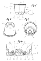
- a means 16 is shown, which is suitable for the penetration of the bottom 4 of the capsule 1.
- This means has a bottom plate 17 with a central, preferably frusto-conical elevation 20 and with a peripheral outer wall 37.
- an annular trough or penetration zone 18 is formed, in which preferably a plurality of penetration elements 19 are arranged in a circular manner. These have the form of obliquely cut cylinders or cones with a directed against the lid of the capsule tip or cutting edge 21.
- a drain channel 22 which also extends through the bottom plate 17.
- Each drainage channel opens against a side surface 23 of a penetration element which lies below or within a point or cutting edge 21. As shown in the exemplary embodiment, all side surfaces 23 face the center or the elevation 20.
- a helical compression spring 26 may be attached, which is compressed during the penetration process to block and which facilitates the subsequent detachment of the capsule.
- a continuous opening 27 can be arranged in the center of the elevation 20, which prevents an air cushion from being able to build up above the elevation 20.
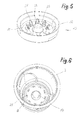
- FIG. 6 shows the same situation when penetrating the capsule bottom as FIG. 4 ie immediately after the tips of the penetration elements 19 have pierced the bottom 11 of the channel in the capsule, but not yet the entire cross-section of the openings 24 is exposed.
- the bottom 11 of the channel during the penetration process against the unloaded position ( Fig. 1 ) something raised.
- the bottom 11 remains plane-parallel due to the stiffening by the inner wall portion 9, whereby the penetration of a high resistance is opposed.
- the required for the penetration rice tension is achieved immediately and the bottom 11 suffers no inadmissible deflection.
- the bottom of the capsule is pressed in a form-fitting and pressure-tight manner against the bottom plate 17 and thus the maximum outflow cross-section at the openings 24 is reached.
- the extract then flows through the drainage channels 22 (FIG. Fig. 7 ), where it can be properly intercepted and channeled away.
- FIGS. 8 and 9 show a cross section through a brewing module of a coffee machine for a capsule according to FIG. 1 and using a penetrant 16 according to FIG. 5 ,
- the essential elements of this device 28 consist of a capsule holder 29, in the bottom of which the described penetration means 16 is installed.
- the capsule holder can be closed or sealed with a closure part 30 to a brewing chamber.
- the closure member is in turn provided with a plurality of penetration elements 31 which may be similarly configured and arranged as those on the penetration means 16.
- the closure member 30 is mounted on a support 36 which in a frame 34 by means of a lever mechanism 35 linearly against the capsule holder 29 or can be moved away from this.
- the capsule 1 When the brewing chamber is completely closed according to FIG. 9 the capsule 1 is penetrated at its lid and at its bottom. Brewing water is introduced via an inlet 32 via a pump, not shown here, or passed through the capsule from the lid against the ground. The extract, so for example, the finished coffee flows through a drain 33.
- the capsule 1 differs from that according to FIG. 1 in that the inner wall part 9 of the annular groove 8 merges at its cover-side end into a convexly curved central floor section.
- the outer wall portion 12 of the channel 8 merges seamlessly and without changing the diameter directly into the side wall 3.
- the central wall portion 15 is formed such that it can be slipped by a force from the outside against the lid 5, which evidently reduces the volume of the chamber 6 slightly.
- This process is in the device 28 according to the FIGS. 13 and 14 shown.
- the helical compression spring 26 is already at this bottom portion and exerts an increasing force on him.
- the elevation 20 in the penetration means 16 is not frustoconical in this case, but is formed like a dome.
- the stiffening zone forms a cylindrical body, which tapers conically towards the cover.
- the inner wall part of the channel 8 is thus obviously composed of a cylindrical portion 9a and a conical portion 9b.
- the stiffening zone is dome-shaped, which in the present case is a spherical cap.
- the inner wall section 9 forms a spherical section.
- the inner wall part could have different angles of inclination, curvatures or wall thicknesses.
- the stiffening zone in the center of the annular groove by additional wall sections, such as e.g. statisticalsteifen by star-shaped fins.
- the means for penetrating the bottom of the capsule is adapted in each case in the center of the annular penetration zone of the configuration of the stiffening zone in order to ensure optimum centering.
Landscapes
- Engineering & Computer Science (AREA)
- Mechanical Engineering (AREA)
- Food Science & Technology (AREA)
- Apparatus For Making Beverages (AREA)
- Supplying Of Containers To The Packaging Station (AREA)
- Packging For Living Organisms, Food Or Medicinal Products That Are Sensitive To Environmental Conditiond (AREA)
- Formation And Processing Of Food Products (AREA)
- Closures For Containers (AREA)
- Containers Opened By Tearing Frangible Portions (AREA)
Abstract
Description
Die Erfindung betrifft eine Kapsel gemäss dem Oberbegriff von Anspruch 1. Derartige Kapseln werden heute verbreitet als Portionenpackungen für die Zubereitung von z.B. Kaffee verwendet. Der Verbraucher muss sich nicht mehr um die Dosierung der richtigen Kaffeemenge kümmern und nach dem Extraktionsvorgang wird die Kapsel samt Inhalt entsorgt.The invention relates to a capsule according to the preamble of
Das Kaffeepulver bleibt ausserdem in der geschlossenen Kammer aromadicht verpackt und ist vor Feuchtigkeit geschützt.The coffee powder also remains packed in the closed chamber aroma-tight and is protected from moisture.
Vergleichbare Kapseln sind beispielsweise durch die
Es ist daher eine Aufgabe der Erfindung, eine Kapsel der eingangs genannten Art zu schaffen, die in einer eigens dafür vorgesehenen Zone möglichst durch eine Vielzahl von Penetrationsmitteln penetrierbar ist, ohne dass es zu unerwünschten Deformationen am Boden der Kapsel kommt. Diese Aufgabe wird durch eine Kapsel gelöst, welche die Merkmale in Anspruch 1 aufweist. Die Substanz für die Zubereitung des Getränks liegt unmittelbar auf dem Boden der Kapsel auf, ist also nicht durch zusätzliche Filterschichten abgegrenzt, welche eine Penetration zusätzlich erschweren können. Der Boden der Kapsel weist eine kreisringsförmige Rinne auf, deren innere Wandpartie eine vorzugsweise sich gegen den Deckel verjüngende, vorzugsweise kegelstumpfförmige Versteifungszone bildet. Diese Versteifungszone verhindert, dass sich der Kapselboden beim Aufbau der Reisspannung unmittelbar vor der Penetration unzulässig durchbiegen kann. Die erforderliche Reissspannung baut sich somit schlagartig auf, womit eine saubere Penetration des Kapselbodens an der penetrierbaren Zone am Boden der Rinne erzielt wird. Eine kegelstumpfförmige Versteifungszone hat sich aus fabrikationstechnischen und aus festigkeitsmässigen Gründen als vorteilhaft erwiesen. Selbstverständlich könnte diese Versteifungszone je nach Ausgestaltung der inneren Wandpartie auch eine andere Konfiguration aufweisen. Die Höhe der inneren Wandpartie bezogen auf die Längsmittelachse der Kapsel kann kleiner sein als der mittlere Durchmesser der inneren Wandpartie, womit ein ausreichendes Verhältnis zwischen Höhe und Durchmesser der Wandpartie erzielt wird.
Ein weiterer Vorteil der kreisringsförmigen Rinne mit dem penetrierbaren Bodenbereich besteht darin, dass sich beim Durchleiten des Brühwassers vom Deckel gegen den Boden bei entsprechendem Einpressdruck die Flüssigkeit zuerst in der Rinne aufstaut. Unmittelbar vor der Ableitung des Extrakts durch die perforierten Stellen findet dabei eine Art Vorextraktion in der Rinne statt.It is therefore an object of the invention to provide a capsule of the type mentioned, which is penetrated as possible in a specially designated zone by a variety of penetration means, without causing undesirable deformations at the bottom of the capsule. This object is achieved by a capsule, which has the features in
Another advantage of the annular groove with the penetrable bottom area is that when passing the brewing water from the lid against the ground at a corresponding injection pressure, the liquid accumulates first in the gutter. Immediately before the discharge of the extract through the perforated sites takes place a kind of pre-extraction in the gutter.
Die äussere Wandpartie der Rinne kann sich gegen den Deckel ebenfalls vorzugsweise kegelstumpfförmig erweitern und direkt in die Seitenwand der Kapsel übergehen. Es ist aber auch denkbar, dass sich die äussere Wandpartie der Rinne gegen den Deckel vorzugsweise kegelstumpfförmig erweitert und dass sie mit einem Absatz oder mit einem Radius in die Seitenwand übergeht. Mit diesem Absatz oder Radius wird auch auf der Aussenseite der kreisringförmigen Penetrationszone eine Materialversteifung bewirkt, welche die Penetration begünstigt. Es kann dabei zweckmässig sein, wenn die innere Wandpartie der Rinne bis in die Ebene des Absatzes bzw. des Radiusansatzes zwischen der äusseren Wandpartie und der Seitenwand reicht. Besonders optimal lässt sich das Verhältnis zwischen Penetrationszone und Versteifungszone gestalten, wenn die Wandstärke des Bodens im Bereich der penetrierbaren Zone geringer ist als an der inneren und/oder an der äusseren Wandpartie der kreisringförmigen Rinne.The outer wall portion of the gutter may also extend against the lid preferably frusto-conical and pass directly into the side wall of the capsule. But it is also conceivable that the outer wall portion of the groove against the lid preferably widens frustoconical and that it merges with a paragraph or with a radius in the side wall. With this paragraph or radius, a material stiffening is effected on the outside of the annular penetration zone, which favors the penetration. It may be expedient if the inner wall portion of the channel extends into the plane of the shoulder or the radius approach between the outer wall portion and the side wall. The ratio between penetration zone and stiffening zone can be designed particularly optimally if the wall thickness of the floor is less in the region of the penetratable zone than on the inner and / or on the outer wall section of the annular groove.
Weitere Vorteile können erreicht werden, wenn die innere Wandpartie an ihrem deckelseitigen Ende in einen zentralen Bodenabschnitt übergeht, der parallel zum Boden der Rinne verläuft. Der zentrale Bodenabschnitt kann dabei in der Ebene des Absatzes oder des Radiusansatzes zwischen der äusseren Wandpartie und der Seitenwand verlaufen.Further advantages can be achieved if the inner wall section merges at its lid-side end into a central bottom section, which runs parallel to the bottom of the channel. The central bottom portion may extend in the plane of the paragraph or the radius approach between the outer wall portion and the side wall.
Die innere Wandpartie kann an ihrem deckelseitigen Ende aber auch in einen konkav nach innen gewölbten zentralen Bodenabschnitt übergehen. Damit wird ein kuppelartiger Effekt erzielt, der die innere Wandpartie der Rinne besonders vorteilhaft versteift. Ebenso gut kann die innere Wandpartie aber an ihrem deckelseitigen Ende in einen konvex nach aussen gewölbten zentralen Bodenabschnitt übergehen. Damit wird der gleiche Effekt erzielt, wie mit der konkaven Wölbung. Der zentrale Bodenabschnitt kann ausserdem derart flexibel ausgestaltet sein, dass er durch eine Kraft von aussen konkav nach innen stülpbar ist. Dadurch könnte beispielsweise eine Reduktion des Kapselvolumens und damit eine Verdichtung der darin befindlichen Substanz erzielt werden. Auch ein geringer Überdruck liesse sich mit einer derartigen Bodendeformation erzielen, was die Perforation weiter begünstigen könnte.The inner wall portion can pass at its lid-side end but also in a concave inwardly curved central floor section. For a dome-like effect is achieved, which stiffen the inner wall portion of the channel particularly advantageous. But the inner wall section can just as well pass over at its lid-side end into a convexly outwardly curved central floor section. This achieves the same effect as with the concave curvature. The central floor section can also be designed so flexible that it can be turned concavely inwards by a force from the outside. As a result, for example, a reduction of the capsule volume and thus a compression of the substance contained therein could be achieved. Even a slight overpressure could be achieved with such a soil deformation, which could further promote the perforation.
Die Erfindung betrifft auch ein Mittel zum Penetrieren des Bodens einer vorstehend beschriebenen Kapsel, mit einer Bodenplatte, die eine kreisringförmige Penetrationszone aufweist, auf der mehrere Penetrationselemente angeordnet sind, wobei im Zentrum der Penetrationszone eine vorzugsweise kegelstumpfförmige Erhöhung angeordnet ist. Diese zentrale Erhöhung dringt ersichtlicherweise in die zentrale Bodenaussparung an der Kapsel und bewirkt dadurch ein Zentrieren der Kapsel während der Penetration.The invention also relates to a means for penetrating the bottom of a capsule described above, comprising a bottom plate having an annular penetration zone on which a plurality of penetration elements are arranged, wherein in the center of the penetration zone a preferably frusto-conical elevation is arranged. Evidently, this central elevation penetrates into the central bottom recess on the capsule and thereby causes centering of the capsule during penetration.
Die Penetrationszone bildet vorzugsweise ebenfalls eine kreisringförmige Wanne, welche mit der kreisringförmigen Rinne der Kapsel korrespondiert.The penetration zone also preferably forms an annular trough, which corresponds to the annular groove of the capsule.
Die Penetrationselemente können sich zu einer Spitze oder zu einer Schneide verjüngende Körper mit einem Ablaufkanal bilden, der sich durch die Bodenplatte erstreckt und der sich gegen eine Seitenfläche des Körpers öffnet. Ersichtlicherweise dienen derartige Penetrationselemente nicht nur der eigentlichen Penetration der Kapsel, sondern auch unmittelbar der Ableitung der Flüssigkeit. Die Öffnungen in den Seitenflächen der Körper können dabei mit einer Siebfolie bedeckt sein. Die Filter- oder Siebwirkung beim Ableiten der Flüssigkeit wird dabei unmittelbar an den Penetrationselementen erzielt. Die Siebfolie kann mit derart feinen Öffnungen versehen sein, dass selbst feinste Festpartikel zurückgehalten werden. Anstelle der Siebfolie wäre es aber auch denkbar, die Penetrationselemente mit einer Mehrzahl von sehr feinen Bohrungen zu versehen, welche von aussen in den Ablaufkanal führen.The penetration elements may form into a tip or blade tapered body having a drainage channel extending through the base plate and opening against a side surface of the body. Evidently, such penetration elements serve not only the actual penetration of the capsule, but also directly the discharge of the liquid. The openings in the side surfaces of the body can be covered with a screen. The filtering or sieving effect during the discharge of the liquid is achieved directly at the penetration elements. The screen film can be provided with such fine openings that even the finest solid particles are retained. Instead of the screen film but it would also be conceivable, the penetration elements with a plurality to provide very fine holes, which lead from the outside into the drainage channel.
Die Öffnungen des Ablaufkanals können jeweils in einer Seitenfläche der Körper angeordnet sein, welche der zentralen Erhöhung zugewandt ist. Damit wird beim Extraktionsvorgang in der Kapsel eine Strömung erzwungen, die vom Zentrum nach aussen gegen die Penetrationselemente verläuft.The openings of the drainage channel can each be arranged in a side surface of the body, which faces the central elevation. Thus, a flow is forced during the extraction process in the capsule, which runs from the center to the outside against the penetration elements.
Die Penetrationselemente können dabei etwa gleich hoch sein wie die vorzugsweise kegelstumpfförmige Erhöhung im Zentrum. Auf der vorzugsweise kegelstumpfförmigen Erhöhung kann ausserdem eine Schraubendruckfeder angeordnet sein, deren freies Ende an den Boden einer gegen die Bodenplatte pressbaren Kapsel anlegbar ist. Diese Schraubendruckfeder bewirkt eine von der Bodenplatte weggerichtete Kraft, welche das Ablösen der Kapsel von der Bodenplatte bzw. von den Penetrationselementen erleichtert. Ersichtlicherweise dient die zentrale Erhöhung am Kapselboden unter anderem auch der Zentrierung dieser Schraubendruckfeder.The penetration elements can be about the same height as the preferably frusto-conical elevation in the center. On the preferably frusto-conical increase may also be arranged a helical compression spring, the free end of which can be applied to the bottom of a pressed against the bottom plate capsule. This helical compression spring causes a directed away from the bottom plate force which facilitates the detachment of the capsule from the bottom plate or from the penetration elements. Evidently, the central increase in the capsule bottom, inter alia, also serves to center this helical compression spring.
Schliesslich betrifft die Erfindung auch eine Vorrichtung für die Zubereitung eines Getränks mit den Merkmalen im Anspruch 18. Diese Vorrichtung ermöglicht eine simultane Penetration der Kapsel am Deckel und am Boden, wobei das Öffnen und Schliessen der beiden Kammerteile auf unterschiedliche Weise erfolgen kann. Auch die Relativlage der Kapsel zum Zeitpunkt der Penetration spielt grundsätzlich keine Rolle.Finally, the invention also relates to a device for the preparation of a beverage with the features in
Weitere Vorteile und Einzelmerkmale der Erfindung ergeben sich aus den nachstehend beschriebenen Ausführungsbeispielen und aus den Zeichnungen. Es zeigen:
- Figur 1:
- Einen Querschnitt durch eine erste Ausführungsform einer erfindungsgemässen Kapsel,
- Figur 2:
- eine perspektivische Darstellung der Kapsel gemäss
Figur 1 - Figur 3:
- eine perspektivische Darstellung der Kapsel gemäss
Figur 1 - Figur 4:
- eine geschnittene, perspektivische Darstellung der Unterseite der Kapsel gemäss
Figur 1 - Figur 5:
- eine perspektivische Gesamtdarstellung des Penetrationsmittels gemäss
Figur 4 - Figur 6:
- eine perspektivische Darstellung mit Blick ins Innere der Kapsel gemäss
Figur 4 , - Figur 7:
- eine perspektivische Darstellung mit Blick auf den Boden des Penetrationsmittels gemäss
Figur 4 , - Figur 8:
- eine Brühvorrichtung für eine Kapsel gemäss
Figur 1 vor dem Schliessen der Kavität, - Figur 9:
- die
Vorrichtung gemäss Figur 8 bei geschlossener Kavität, - Figur 10:
- ein Querschnitt durch eine zweite Ausführungsform einer erfindungsgemässen Kapsel,
- Figur 11:
- eine perspektivische Darstellung der Kapsel gemäss
Figur 10 mit Blick auf den Boden, - Figur 12:
- eine perspektivische Darstellung der Kapsel gemäss
Figur 10 mit Blick ins Innere der Kapsel, - Figur 13:
- ein Querschnitt durch eine Brühvorrichtung zum Brühen der Kapsel gemäss
Figur 10 bei geöffneter Kavität, - Figur 14:
- die
Vorrichtung gemäss Figur 13 bei geschlossener Kavität, - Figur 15:
- einen Querschnitt durch einen Kapselboden mit kegelstumpfförmiger Versteifungszone,
- Figur 16:
- einen Querschnitt durch einen Kapselboden mit zylindrischer und kegelförmiger Versteifungszone und
- Figur 17:
- einen Querschnitt durch einen Kapselboden mit kalottenförmiger Versteifungszone.
- FIG. 1:
- A cross section through a first embodiment of a capsule according to the invention,
- FIG. 2:
- a perspective view of the capsule according to
FIG. 1 facing the ground, - FIG. 3:
- a perspective view of the capsule according to
FIG. 1 with a view of the capsule inside, - FIG. 4:
- a sectional perspective view of the underside of the capsule according to
FIG. 1 when penetrating a penetrant, - FIG. 5:
- an overall perspective view of the penetrant according to
FIG. 4 . - FIG. 6:
- a perspective view with a view into the interior of the capsule according
FIG. 4 . - FIG. 7:
- a perspective view overlooking the bottom of the penetrant according to
FIG. 4 . - FIG. 8:
- a brewing device for a capsule according to
FIG. 1 before closing the cavity, - FIG. 9:
- the device according to
FIG. 8 with closed cavity, - FIG. 10:
- a cross section through a second embodiment of a capsule according to the invention,
- FIG. 11:
- a perspective view of the capsule according to
FIG. 10 facing the ground, - FIG. 12:
- a perspective view of the capsule according to
FIG. 10 looking inside the capsule, - FIG. 13:
- a cross section through a brewing device for brewing the capsule according to
FIG. 10 with open cavity, - FIG. 14:
- the device according to
FIG. 13 with closed cavity, - FIG. 15:
- a cross section through a capsule bottom with frustoconical stiffening zone,
- FIG. 16:
- a cross section through a capsule bottom with cylindrical and conical stiffening zone and
- FIG. 17:
- a cross section through a capsule bottom with dome-shaped stiffening zone.
Wie aus den
Der topfartige Kapselkörper 2 ist an seinem oberen Ende mit einem Deckel 5 verschlossen, der vorzugsweise ebenfalls aus Kunststoffmaterial besteht und der im Umfangsbereich des Kapselkörpers angeschweisst oder angeklebt wird. Die Kapsel bildet auf diese Weise eine geschlossene, hermetisch dichte Kammer 6, die mit einer Substanz 7 für die Herstellung eines Getränks gefüllt ist. Die Füllung muss nicht zwingend dem maximal möglichen Volumen der Kammer 6 entsprechen. Zum Schutz der Füllung kann die Kammer 6 auch noch mit einem Inertgas gefüllt sein. Bei der Substanz 7 kann es sich beispielsweise um Kaffeepulver oder um Tee handeln, wobei beim Durchströmen der Kapsel mit heissem Wasser ein Extraktionsprozess stattfindet. Bei der Substanz 7 könnte es sich aber beispielsweise auch um einen Trockenextrakt handeln, der beim Durchströmen mit heissem oder mit kaltem Wasser vollständig in Lösung übergeht, so dass zuletzt keine Rückstände in der Kapsel verbleiben. Denkbar wäre z.B. ein Trockenextrakt für die Herstellung eines Fruchtgetränks oder einer Bouillon.The cup-shaped
Die Substanz 7 liegt ohne Filterschichten oder dergleichen unmittelbar auf dem Boden 4 des Kapselkörpers 2 auf. Voraussetzung dafür ist die nachstehend noch beschriebene, besondere Art der Penetration des Kapselbodens bzw. die Ausgestaltung des Kapselbodens selbst. Dieser weist eine kreisringförmige Rinne 8 auf, deren innere Wandpartie 9 sich gegen den Deckel hin vorzugsweise kegelstumpfförmig im Durchmesser verjüngt. Die äussere Wandpartie 12 der Rinne 8 erweitert sich vorzugsweise mit der gleichen Winkelneigung relativ zur Längsmittelachse 10 wie die innere Wandpartie 9. Die Höhe hr der Rinne 8 in Richtung der Längsmittelachse 10 ist in jedem Fall kleiner als der mittlere Durchmesser dm der inneren Wandpartie 9 und vorzugsweise auch kleiner als die mittlere Breite der Rinne. Die innere Wandpartie 9 bildet eine Versteifungszone, welche der Penetration am Boden 11 der Rinne einen Widerstand entgegensetzt. Die gleiche Funktion kann auch die äussere Wandpartie 12 ausüben, wobei es denkbar ist, dass die Wandstärke der inneren Wandpartie 9 und der äusseren Wandpartie 12 insbesondere gegenüber dem Boden 11 der Rinne etwas verstärkt ausgebildet ist.The
Das deckelseitige obere Ende der inneren Wandpartie 9 geht in einen zentralen Bodenabschnitt 14 über, der parallel zum Boden 11 der Rinne verläuft. Auf der gleichen Ebene des zentralen Bodenabschnitts 14 geht die äussere Wandpartie 12 mit einem Radius 13 in die Seitenwand 3 über. Der Übergang könnte auch mit einem Absatz erfolgen, der im rechten Winkel oder schräg zur Längsmittelachse 10 verläuft.The lid-side upper end of the
In den
Zum Erzielen einer Filterwirkung sind die Öffnungen 24 in den Seitenflächen 23 mit einer Siebfolie 25 (
Wie aus
Sobald der Druckaufbau in der Kapsel einsetzt, wird der Boden der Kapsel formschlüssig und druckdicht gegen die Bodenplatte 17 gepresst und damit der maximale Abflussquerschnitt an den Öffnungen 24 erreicht. Der Extrakt fliesst danach durch die Ablaufkanäle 22 (
As soon as the build-up of pressure in the capsule begins, the bottom of the capsule is pressed in a form-fitting and pressure-tight manner against the
Die
Bei vollständig geschlossener Brühkammer gemäss
Beim Ausführungsbeispiel gemäss den
Dieser Vorgang ist in der Vorrichtung 28 gemäss den
Noch vor Erreichen der Schliessstellung gemäss
Beim Ausführungsbeispiel gemäss
Beim Ausführungsbeispiel gemäss
Selbstverständlich sind alternative Ausführungsformen zur Bildung der zentralen Versteifungszone denkbar. Insbesondere könnte die innere Wandpartie unterschiedliche Neigungswinkel, Krümmungen oder Wandstärken haben. Bei Kapselkörpern, welche in einem Spritzgiessverfahren hergestellt werden, wäre es ausserdem denkbar, die Versteifungszone im Zentrum der kreisringförmigen Rinne durch zusätzliche Wandabschnitte wie z.B. durch sternförmige Lamellen auszusteifen. Das Mittel zum Penetrieren des Bodens der Kapsel ist jeweils im Zentrum der kreisringförmigen Penetrationszone der Konfiguration der Versteifungszone angepasst, um eine optimale Zentrierung zu gewährleisten.Of course, alternative embodiments for forming the central stiffening zone are conceivable. In particular, the inner wall part could have different angles of inclination, curvatures or wall thicknesses. In the case of capsule bodies which are produced in an injection molding process, it would also be conceivable to use the stiffening zone in the center of the annular groove by additional wall sections, such as e.g. auszusteifen by star-shaped fins. The means for penetrating the bottom of the capsule is adapted in each case in the center of the annular penetration zone of the configuration of the stiffening zone in order to ensure optimum centering.
Claims (19)
Priority Applications (17)
| Application Number | Priority Date | Filing Date | Title |
|---|---|---|---|
| DE200750004474 DE502007004474D1 (en) | 2007-01-15 | 2007-01-15 | Capsule, means for penetrating the bottom of a capsule and device for the preparation of a drink |
| ES07100520.1T ES2661027T3 (en) | 2007-01-15 | 2007-01-15 | Capsule, means of penetration of the bottom of a capsule and device for preparing a beverage |
| PL07100520T PL1944248T3 (en) | 2007-01-15 | 2007-01-15 | Capsule, means for penetrating the bottom of a capsule and device for preparing a drink |
| AT07100520T ATE474798T1 (en) | 2007-01-15 | 2007-01-15 | CAPSULE, MEANS FOR PENETRATING THE BOTTOM OF A CAPSULE AND DEVICE FOR PREPARING A BEVERAGE |
| PT71005201T PT1944248T (en) | 2007-01-15 | 2007-01-15 | Capsule, means for penetrating the bottom of a capsule and device for preparing a drink |
| EP07100520.1A EP1944248B1 (en) | 2007-01-15 | 2007-01-15 | Capsule, means for penetrating the bottom of a capsule and device for preparing a drink |
| US12/523,121 US9248955B2 (en) | 2007-01-15 | 2008-01-11 | Capsule, means for piercing the base of a capsule and device for preparing a beverage |
| AU2008207022A AU2008207022B2 (en) | 2007-01-15 | 2008-01-11 | Capsule, means for piercing the base of a capsule and device for preparing a beverage |
| CN2008800021392A CN101636333B (en) | 2007-01-15 | 2008-01-11 | Capsule, means for penetrating the bottom of a capsule and device for preparing a drink |
| CA 2674483 CA2674483C (en) | 2007-01-15 | 2008-01-11 | Capsule, means for piercing the base of a capsule and device for preparing a beverage |
| MX2009007587A MX2009007587A (en) | 2007-01-15 | 2008-01-11 | Capsule, means for piercing the base of a capsule and device for preparing a beverage. |
| PCT/EP2008/050271 WO2008087099A2 (en) | 2007-01-15 | 2008-01-11 | Capsule, means for piercing the base of a capsule and device for preparing a beverage |
| EP08701417A EP2102078A2 (en) | 2007-01-15 | 2008-01-11 | Capsule, means for piercing the base of a capsule and device for preparing a beverage |
| RU2009131052A RU2433077C2 (en) | 2007-01-15 | 2008-01-11 | Capsule, capsule bottom borer and device for drink preparation |
| BRPI0806569-1A BRPI0806569B1 (en) | 2007-01-15 | 2008-01-11 | CAPSULE, CAPSULE BODY FOR A CAPSULE, MEDIA FOR PENETRATION OF A CAPSULE BASE, AND DEVICE FOR PREPARING A DRINK BY USING A CAPSULE |
| KR1020097016819A KR101519933B1 (en) | 2007-01-15 | 2008-01-11 | Capsule, means for piercing the base of a capsule and device for preparing a beverage |
| JP2009545893A JP5205392B2 (en) | 2007-01-15 | 2008-01-11 | Capsule, capsule-based piercing means and beverage production device |
Applications Claiming Priority (1)
| Application Number | Priority Date | Filing Date | Title |
|---|---|---|---|
| EP07100520.1A EP1944248B1 (en) | 2007-01-15 | 2007-01-15 | Capsule, means for penetrating the bottom of a capsule and device for preparing a drink |
Publications (2)
| Publication Number | Publication Date |
|---|---|
| EP1944248A1 true EP1944248A1 (en) | 2008-07-16 |
| EP1944248B1 EP1944248B1 (en) | 2017-12-13 |
Family
ID=38564538
Family Applications (2)
| Application Number | Title | Priority Date | Filing Date |
|---|---|---|---|
| EP07100520.1A Active EP1944248B1 (en) | 2007-01-15 | 2007-01-15 | Capsule, means for penetrating the bottom of a capsule and device for preparing a drink |
| EP08701417A Withdrawn EP2102078A2 (en) | 2007-01-15 | 2008-01-11 | Capsule, means for piercing the base of a capsule and device for preparing a beverage |
Family Applications After (1)
| Application Number | Title | Priority Date | Filing Date |
|---|---|---|---|
| EP08701417A Withdrawn EP2102078A2 (en) | 2007-01-15 | 2008-01-11 | Capsule, means for piercing the base of a capsule and device for preparing a beverage |
Country Status (16)
| Country | Link |
|---|---|
| US (1) | US9248955B2 (en) |
| EP (2) | EP1944248B1 (en) |
| JP (1) | JP5205392B2 (en) |
| KR (1) | KR101519933B1 (en) |
| CN (1) | CN101636333B (en) |
| AT (1) | ATE474798T1 (en) |
| AU (1) | AU2008207022B2 (en) |
| BR (1) | BRPI0806569B1 (en) |
| CA (1) | CA2674483C (en) |
| DE (1) | DE502007004474D1 (en) |
| ES (1) | ES2661027T3 (en) |
| MX (1) | MX2009007587A (en) |
| PL (1) | PL1944248T3 (en) |
| PT (1) | PT1944248T (en) |
| RU (1) | RU2433077C2 (en) |
| WO (1) | WO2008087099A2 (en) |
Cited By (12)
| Publication number | Priority date | Publication date | Assignee | Title |
|---|---|---|---|---|
| DE102008041793A1 (en) * | 2008-09-03 | 2010-03-04 | BSH Bosch und Siemens Hausgeräte GmbH | Disposable beverage powder capsule i.e. used coffee capsule, opening device for recycling e.g. capsule material, has holding unit, where device moves capsule, which is provided in holding unit, to cutting unit, to cut-open cover |
| WO2010041179A3 (en) * | 2008-10-08 | 2010-09-02 | Ethical Coffee Company Sa | Capsule for preparing a beverage |
| WO2011035360A1 (en) * | 2009-09-28 | 2011-03-31 | Sunday Products Handels Gmbh & Co Kg | Coffee capsule |
| EP2368466A1 (en) | 2010-03-24 | 2011-09-28 | Delica AG | Device for preparing a drink |
| WO2012080501A1 (en) | 2010-12-17 | 2012-06-21 | Delica Ag | Capsule, system, and method for preparing a beverage |
| CN103327856A (en) * | 2011-01-24 | 2013-09-25 | 雀巢产品技术援助有限公司 | Capsule and method for the preparation of a beverage by centrifugation |
| CN104334472A (en) * | 2012-03-05 | 2015-02-04 | 马基雅维利有限责任公司 | Interchangeable capsule for the preparation of an infusion of a powdered product, and relative method for obtaining such an infusion |
| JP2015523881A (en) * | 2012-06-08 | 2015-08-20 | ルイジ ラバッツァ ソシエタ ペルアチオニLuigi Lavazza S.p.A. | Delivery assembly for a machine for preparing a liquid product using a capsule, a machine for preparing a liquid product with a capsule, and a system and method for preparing a liquid product |
| USD742221S1 (en) * | 2013-08-13 | 2015-11-03 | Caffitaly System S.P.A. | Capsule for making beverages |
| US9307857B2 (en) | 2009-06-17 | 2016-04-12 | Koninklijke Douwe Egberts B.V. | Capsule, system and method for preparing a predetermined quantity of beverage suitable for consumption |
| EP2782849B1 (en) | 2011-11-22 | 2016-06-01 | Tuttoespresso S.r.l. | Capsule and system for beverage preparation |
| CN107019430A (en) * | 2017-05-19 | 2017-08-08 | 肖亚莉 | Can constant structure of container, preparation method and its method for pouring for piercing through pressure |
Families Citing this family (141)
| Publication number | Priority date | Publication date | Assignee | Title |
|---|---|---|---|---|
| US8431175B2 (en) | 2007-06-05 | 2013-04-30 | Nestec S.A. | Method for preparing a beverage or food liquid and system using brewing centrifugal force |
| RU2479242C2 (en) * | 2007-06-05 | 2013-04-20 | Нестек С.А. | System for capsules, device and method for containerised food liquid preparation by way of centrifugation |
| EP2152607B1 (en) | 2007-06-05 | 2012-01-11 | Nestec S.A. | Single-use capsule for preparing a food liquid by centrifugation |
| BRPI0812449B1 (en) | 2007-06-05 | 2018-09-25 | Nestec Sa | capsule for the preparation of liquid food by centrifugation |
| DE602008006068D1 (en) | 2007-06-05 | 2011-05-19 | Nestec Sa | METHOD FOR PRODUCING A BEVERAGE OR LIQUID FOOD |
| US11832755B2 (en) * | 2007-07-13 | 2023-12-05 | Adrian Rivera | Brewing material container for a beverage brewer |
| WO2009084059A1 (en) * | 2008-01-03 | 2009-07-09 | Essence-Sbt Sa | System for delivering infusion beverages and infusion capsule |
| CA2734935C (en) | 2008-09-02 | 2015-02-10 | Nestec S.A. | Controlled beverage production device using centrifugal forces |
| EP2330953B1 (en) | 2008-09-02 | 2015-06-03 | Nestec S.A. | Method for preparing a food liquid contained in a capsule by centrifugation and system adapted for such method |
| WO2010028282A1 (en) * | 2008-09-04 | 2010-03-11 | Razbaby Innovative Baby Products, Inc. | Infant formula preparation apparatus and method |
| WO2010066736A1 (en) | 2008-12-09 | 2010-06-17 | Nestec S.A. | Liquid food preparation system for preparing a liquid food by centrifugation |
| EP2196407B2 (en) | 2008-12-10 | 2017-06-28 | Delica AG | Capsule and device for preparing a drink |
| IT1393936B1 (en) * | 2009-04-09 | 2012-05-17 | I T A Ca S R L Ora Mitaca S R L | CARTRIDGE FOR COFFEE AND SOLUBLE PRODUCTS FOR THE PREPARATION OF DRINKS |
| JP2012523861A (en) * | 2009-04-15 | 2012-10-11 | ルナ・テクノロジー・システムズ・エル・テー・エス・ゲゼルシャフト・ミット・べシュレンクテル・ハフツング | Device, puncture device, and extraction device for removing extraction product from portion package |
| KR101497773B1 (en) * | 2009-06-17 | 2015-03-02 | 코닌클리케 도우베 에그베르츠 비.브이. | System and method for preparing a predetermined quantity of beverage |
| IT1397068B1 (en) * | 2009-06-24 | 2012-12-28 | Swiss Caffe Asia Ltd | DRILLING DEVICE, PARTICULARLY FOR CAPSULES FOR THE PREPARATION OF BEVERAGES AND THE LIKE. |
| EP2308776B1 (en) * | 2009-08-19 | 2013-05-29 | Nestec S.A. | Capsule system comprising a capsule and a water injection device |
| US8658232B2 (en) | 2009-08-28 | 2014-02-25 | Nestec S.A. | Capsule system for the preparation of beverages by centrifugation |
| JP5722895B2 (en) | 2009-08-28 | 2015-05-27 | ネステク ソシエテ アノニム | Capsule system for beverage preparation by centrifugation |
| JP5763905B2 (en) * | 2009-10-30 | 2015-08-12 | ネステク ソシエテ アノニム | Capsule for producing coffee extract with structure facilitating perforation for water injection |
| DE102009058646A1 (en) * | 2009-12-16 | 2011-06-22 | Krüger GmbH & Co. KG, 51469 | Portion capsule and use of a portion capsule |
| ES2388892T3 (en) | 2009-12-18 | 2012-10-19 | Delica Ag | Device for preparing a drink and capsule |
| DE202010006556U1 (en) * | 2010-05-06 | 2010-08-05 | Mahlich, Gotthard | Brewing or preparation chamber for a beverage preparation device |
| US20130129876A1 (en) | 2010-05-20 | 2013-05-23 | Teatek Co., Ltd. | Beverage Substance Cartridge, Identifying Apparatus, Beverage Producing Equipment, Beverage Producing System and Beverage Producing Method |
| DE102010044945A1 (en) | 2010-05-28 | 2011-12-01 | Eugster/Frismag Ag | Brewing device for extracting a portion capsule, method for operating a brewing device, method for producing a brewing device and use of a brewing device |
| EP2394932B1 (en) * | 2010-06-11 | 2013-06-05 | Alain Frydman | Capsule with weakened area |
| WO2011159162A1 (en) * | 2010-06-18 | 2011-12-22 | Biserkon Holdings Ltd. | Capsule, device and method for preparing a beverage by extraction |
| PT2409609E (en) * | 2010-07-22 | 2013-01-07 | Nestec Sa | A capsule holder or an adapter for adapting a capsule in a capsule holder in a beverage preparation machine |
| PL3521207T3 (en) * | 2010-07-22 | 2020-06-15 | K-Fee System Gmbh | Portion capsule with barcode |
| IT1402818B1 (en) * | 2010-11-10 | 2013-09-27 | E T I S R L | CAPSULE TO CONTAIN A PREPARATION FOR HOT DRINK |
| ITPD20100358A1 (en) * | 2010-11-25 | 2012-05-26 | Michele Scapuccin | NESPRESSO COMPATIBLE CAPSULE TM |
| ITGE20100135A1 (en) * | 2010-12-10 | 2012-06-11 | Espressocap Srl | PRE-PACKAGING CHARGE FOR ESPRESSO COFFEE MACHINES AND DISPENSER GROUP SUITABLE FOR THE USE OF THIS CHARGE |
| IT1403914B1 (en) * | 2011-02-04 | 2013-11-08 | Technology For Beverage Srl | METHOD OF INTRODUCTION OF WATER INSIDE A CLOSED CAPSULE FOR THE INFUSION OF AN AROMATIC ESSENCE PUT INSIDE THE CAPSULE, CONTAINMENT CAPSULE OF AN AROMATIC ESSENCE THAT IS SUBJECT TO INFUSION, AND A PERFORATION DEVICE OF SUCH A CAPSULE |
| GB2488799A (en) | 2011-03-08 | 2012-09-12 | Kraft Foods R & D Inc | Drinks Pod without Piercing of Outer Shell |
| USD694620S1 (en) | 2011-03-08 | 2013-12-03 | Kraft Foods R&D, Inc. | Beverage cartridge |
| US9114902B2 (en) * | 2011-03-22 | 2015-08-25 | Polyone Designed Structures And Solutions Llc | Methods and systems for use in forming an article from a multi-layer sheet structure |
| GB2489409B (en) | 2011-03-23 | 2013-05-15 | Kraft Foods R & D Inc | A capsule and a system for, and a method of, preparing a beverage |
| PT105598B (en) | 2011-03-30 | 2020-01-17 | Novadelta Comercio E Ind De Cafes Lda | CONTROLLED OPENING CAPSULE, PROCESS AND OPERATING DEVICE OF THIS CAPSULE |
| CN102166096B (en) * | 2011-04-10 | 2012-11-21 | 九阳股份有限公司 | Beverage preparation method |
| EP2520202B1 (en) * | 2011-05-02 | 2014-07-23 | Mocoffee AG | Device and capsule for preparing a beverage |
| GB2491154B (en) | 2011-05-24 | 2013-07-10 | Kraft Foods R & D Inc | Beverage/food product preparation systems |
| ITMI20110923A1 (en) * | 2011-05-24 | 2012-11-25 | Brasilia Spa | DISPOSABLE CAPSULES PRESENTING A CONTAINMENT AREA OF AN AROMATIC ESSENCE FOR THE PRODUCTION OF A FOOD INFUSION |
| DE102011107690A1 (en) * | 2011-07-13 | 2013-01-17 | Eugster/Frismag Ag | Brewing device with a perforation means for generating a vent in a portion capsule |
| ITTV20110105A1 (en) | 2011-07-21 | 2013-01-22 | Hausbrandt Trieste 1829 Spa | DEVICE FOR THE DRILLING OF A SINGLE-DOSE CAPSULE FOR A POWDER AND SIMILAR SUBSTANCE |
| EP2562101A1 (en) * | 2011-08-22 | 2013-02-27 | Nestec S.A. | A capsule for use in a beverage preparation machine |
| ES1075815Y (en) * | 2011-10-25 | 2012-03-08 | Inventos Para Sist S Vending S L | MONODOSIS CAPSULE FOR ESPRESSO COFFEE MACHINES |
| US9492028B2 (en) * | 2012-01-25 | 2016-11-15 | Qbo Coffee Gmbh | Brewing module |
| ITTO20120061A1 (en) * | 2012-01-25 | 2013-07-26 | Lavazza Luigi Spa | SYSTEM AND MACHINE FOR THE PREPARATION OF DRINKS WITH THE USE OF CAPSULES |
| US9144342B2 (en) * | 2012-02-24 | 2015-09-29 | Main Power Electrical Factory, Ltd. | Pod disposal system |
| DE102012006414A1 (en) * | 2012-03-30 | 2013-10-02 | Eugster/Frismag Ag Elektrohaushaltgeräte | Brewing device for extracting a portion capsule and method for operating a brewing device |
| KR20150004390A (en) * | 2012-04-24 | 2015-01-12 | 네스텍 소시에테아노님 | A capsule holder for a beverage preparation machine |
| ITVR20120093A1 (en) * | 2012-05-15 | 2013-11-16 | Coffee Star S A | BEVANADE PRODUCTION SYSTEM |
| BR112015001040A2 (en) * | 2012-07-16 | 2017-06-27 | Tuttoespresso Srl | capsule for preparing a drink and system for preparing a drink |
| USD708057S1 (en) | 2012-09-10 | 2014-07-01 | Kraft Foods R & D, Inc. | Beverage cartridge |
| USD697797S1 (en) | 2012-09-12 | 2014-01-21 | Kraft Foods R&D, Inc. | Beverage cartridge |
| USD686916S1 (en) | 2012-10-26 | 2013-07-30 | Printpack Illinois, Inc. | Container with castle-shaped base |
| USD687297S1 (en) | 2012-10-26 | 2013-08-06 | Printpack Illinois, Inc. | Container with castle-shaped base |
| US9221204B2 (en) * | 2013-03-14 | 2015-12-29 | Kortec, Inc. | Techniques to mold parts with injection-formed aperture in gate area |
| PT106850A (en) * | 2013-03-25 | 2014-09-25 | Galv O E Noronha Lda | BREAKING SYSTEM APPLIED IN CAPSULES FOR EXPRESSED COFFEE MACHINES, TEA OR OTHER SOLUBLE, MADE IN PLASTICS, ALUMINUM OR SIMILAR MATERIALS |
| US9657155B2 (en) * | 2013-04-12 | 2017-05-23 | Printpack Illinois, Inc. | Containers and materials with improved punctureability |
| GB201308927D0 (en) | 2013-05-17 | 2013-07-03 | Kraft Foods R & D Inc | A beverage preparation system, a capsule and a method for forming a beverage |
| DE202014011368U1 (en) | 2013-05-17 | 2019-11-07 | Koninklijke Douwe Egberts B.V. | Beverage manufacturing system and capsule for making a beverage |
| USD746641S1 (en) * | 2013-05-23 | 2016-01-05 | JRAP Inc. | Bento box food container |
| RU2645651C2 (en) * | 2013-05-30 | 2018-02-26 | Туттоэспрессо С.Р.Л. | Capsule, system and method for beverage preparation |
| USD708904S1 (en) | 2013-06-24 | 2014-07-15 | George J. Coyle | Multipurpose plate |
| USD715649S1 (en) | 2013-07-09 | 2014-10-21 | Printpack Illinois, Inc. | Container |
| USD756785S1 (en) * | 2013-07-10 | 2016-05-24 | Sarong Societa' Per Azioni | Capsule |
| CN103417114B (en) * | 2013-07-31 | 2016-03-16 | 广东新宝电器股份有限公司 | Beverage machine and using method thereof |
| EP2850980A1 (en) * | 2013-09-20 | 2015-03-25 | Luna Technology Systems LTS GmbH | Perforation device for a brewing device |
| ITBO20130570A1 (en) * | 2013-10-17 | 2015-04-18 | Aroma System Srl | METHOD FOR THE PRODUCTION OF BEVENADE BY MEANS OF CAPSULES |
| RU2542559C1 (en) * | 2013-11-07 | 2015-02-20 | Общество с ограниченной ответственностью "Фонте Аква" | Beverages preparation capsule (versions) |
| KR101483252B1 (en) * | 2013-11-19 | 2015-01-22 | 주식회사 와이엠쉬핑 | Coffee capsules for a coffee machine |
| AU2013407942B2 (en) * | 2013-12-18 | 2019-09-12 | Tuttoespresso S.R.L. | Capsule and system for the beverage preparation |
| PT2904951T (en) * | 2014-02-06 | 2017-02-21 | Qbo Coffee Gmbh | System for preparing a brewed product |
| CN106572763A (en) * | 2014-03-28 | 2017-04-19 | 埃斯普莱索卡普有限公司 | Pre-packaged charge for espresso coffee making machines |
| WO2015162468A1 (en) * | 2014-04-23 | 2015-10-29 | Caffitaly System S.P.A. | Apparatus and method for making a beverage using a powdered food substance contained in a capsule |
| CN103976657A (en) * | 2014-05-05 | 2014-08-13 | 浙江宏泰锆业科技有限公司 | Ceramic threaded bayonet for coffee machine |
| CA2947914A1 (en) | 2014-06-10 | 2015-12-17 | Printpack Illinois, Inc. | Containers with improved punctureability |
| USD798718S1 (en) | 2014-06-10 | 2017-10-03 | Printpack Illinois, Inc. | Container with cone-shaped base |
| CN104083086B (en) * | 2014-06-20 | 2016-08-31 | 广东新宝电器股份有限公司 | Part is punctured for drinks extraction |
| JP6406933B2 (en) * | 2014-09-01 | 2018-10-17 | 東罐興業株式会社 | Cup for beverage cartridge |
| WO2016054213A1 (en) * | 2014-10-01 | 2016-04-07 | Kraft Foods Group Brands Llc | Coffee pod |
| USD757536S1 (en) | 2014-10-01 | 2016-05-31 | Kraft Foods Group Brands Llc | Container |
| GB201420262D0 (en) | 2014-11-14 | 2014-12-31 | Kraft Foods R & D Inc | A method of forming a cup-shaped body for a beverage capsule |
| WO2016089330A1 (en) * | 2014-12-03 | 2016-06-09 | Arcelik Anonim Sirketi | A capsule suitable to be used in coffee machines |
| EP3031750A1 (en) * | 2014-12-11 | 2016-06-15 | Qbo Coffee GmbH | Beverage capsule, beverage preparation system and method for identifying a beverage capsule |
| EP3031749A1 (en) * | 2014-12-11 | 2016-06-15 | Qbo Coffee GmbH | Beverage capsule, beverage preparation system and method for identifying a beverage capsule |
| EP3031748A1 (en) * | 2014-12-11 | 2016-06-15 | Qbo Coffee GmbH | Beverage capsule, beverage preparation system and method for identifying a beverage capsule |
| JP2018513064A (en) * | 2015-03-23 | 2018-05-24 | アルトリア クライアント サービシーズ エルエルシー | Disposable package for beverage production equipment |
| US10869502B2 (en) * | 2015-07-31 | 2020-12-22 | 14Th Round Inc. | Disposable assembly for vaporizing e-liquid and a method of using the same |
| US20170042362A1 (en) * | 2015-08-14 | 2017-02-16 | Berry Plastics Corporation | Beverage brewing package |
| US10258191B2 (en) | 2015-09-18 | 2019-04-16 | Starbucks Corporation | Beverage dispensing systems and methods |
| US10531761B2 (en) | 2015-09-18 | 2020-01-14 | Starbucks Corporation | Beverage preparation systems and methods |
| CN106562689B (en) * | 2015-10-10 | 2019-05-07 | 漳州灿坤实业有限公司 | The piercing mechanism of material-storing box |
| ITUB20155389A1 (en) * | 2015-11-09 | 2017-05-09 | Sarong Spa | CAPPULE FOR BEVERAGES |
| USD782876S1 (en) * | 2015-12-16 | 2017-04-04 | Ronald M. Rebmann | Communion cup |
| AU2017204680B2 (en) * | 2015-12-31 | 2022-03-24 | Tuttoespresso S.R.L. | A capsule assembly comprising a capsule and a conveyor cap configured to open said capsule |
| ES2939370T3 (en) | 2016-01-12 | 2023-04-21 | Freezio Ag | Dispensing system with cartridge holder |
| DE102016201498B4 (en) * | 2016-02-01 | 2017-08-17 | Norbert Kuhl | OXYGEN-CONTAINED FOOD CONTAINER |
| US11000148B2 (en) | 2016-06-28 | 2021-05-11 | Berry Plastics Corporation | Beverage-brewing package |
| CH712695A1 (en) | 2016-07-07 | 2018-01-15 | Mühlemann Ip Gmbh | One-serving pack for making a beverage from a beverage concentrate. |
| NL2017285B1 (en) | 2016-08-03 | 2018-02-14 | Douwe Egberts Bv | System, apparatus, method, capsule and kit of capsules for preparing a beverage |
| NL2017277B1 (en) | 2016-08-03 | 2018-02-14 | Douwe Egberts Bv | Apparatus and method for preparing a beverage and system comprising the apparatus and an exchangeable capsule |
| NL2017278B1 (en) | 2016-08-03 | 2018-02-14 | Douwe Egberts Bv | System, apparatus, method, capsule and kit of capsules for preparing a beverage |
| NL2017284B1 (en) | 2016-08-03 | 2018-02-14 | Douwe Egberts Bv | System and method for preparing a beverage field and background |
| NL2017280B1 (en) * | 2016-08-03 | 2018-02-14 | Douwe Egberts Bv | System for preparing a beverage |
| NL2019216B1 (en) * | 2016-08-03 | 2018-05-04 | Douwe Egberts Bv | System for preparing a quantity of beverage suitable for consumption |
| NL2017283B1 (en) | 2016-08-03 | 2018-02-14 | Douwe Egberts Bv | System and apparatus for preparing a beverage |
| NL2017281B1 (en) | 2016-08-03 | 2018-02-14 | Douwe Egberts Bv | System for preparing a beverage |
| NL2017279B1 (en) | 2016-08-03 | 2018-02-14 | Douwe Egberts Bv | System for preparing a beverage |
| DE102016116959A1 (en) | 2016-09-09 | 2018-03-15 | Xpressivo Ag | Capsule with arch shape between capsule wall and capsule bottom |
| US20190337713A1 (en) * | 2016-12-30 | 2019-11-07 | Whirlpool Corporation | Single-serving self-piercing pod for liquid and powdered and granular beverage concentrates |
| IT201700016167A1 (en) * | 2017-02-14 | 2018-08-14 | Imper Spa | DISPOSABLE CAPSULE FOR BEVERAGE DELIVERY MACHINES IN THE FORM OF INFUSED |
| USD849596S1 (en) * | 2017-03-24 | 2019-05-28 | Airlite Plastics Co. | Flower pot |
| USD853271S1 (en) * | 2017-03-24 | 2019-07-09 | Airlite Plastics Co. | Flower pot |
| USD852086S1 (en) * | 2017-03-24 | 2019-06-25 | Airlite Plastics Co. | Flower pot |
| USD854411S1 (en) * | 2017-04-05 | 2019-07-23 | Spartech Llc | Beverage pod |
| DE102017109632A1 (en) * | 2017-05-04 | 2018-11-08 | Coveris Rigid (Zell) Deutschland Gmbh | Cup or capsule |
| US11083328B2 (en) | 2017-06-22 | 2021-08-10 | Starbucks Corporation | Apparatus and method for foaming a beverage |
| US11607073B2 (en) | 2017-06-26 | 2023-03-21 | Freezio Ag | Device for producing a beverage |
| KR102481834B1 (en) * | 2017-08-03 | 2022-12-28 | 엘지전자 주식회사 | Beverage maker |
| DE202018106461U1 (en) * | 2017-10-27 | 2018-11-26 | Kiefel Packaging B.V. | Capsule body, brew capsule and container, mold and thermoforming tool |
| US11504898B2 (en) | 2017-10-27 | 2022-11-22 | Kiefel Gmbh | Method of thermoforming a foil, forming tool, thermoforming tool, installation for thermoforming, container and brewing container |
| USD927264S1 (en) * | 2017-11-16 | 2021-08-10 | Ascendo Medienagentur Ag | Capsule |
| WO2019172757A1 (en) * | 2018-03-07 | 2019-09-12 | Euro-Caps Holding B.V. | Capsules for containing a substance from which a beverage can be produced |
| US10696472B2 (en) | 2018-04-30 | 2020-06-30 | Joseph Borse | Single serve beverage container |
| IT201800005334A1 (en) * | 2018-05-14 | 2019-11-14 | Improved capsule. | |
| GB201809708D0 (en) * | 2018-06-13 | 2018-08-01 | Obrist Closures Switzerland | Beverage capsule |
| US11871874B2 (en) * | 2018-07-31 | 2024-01-16 | Moon Sik PARK | Tumbler for preparing beverage and additive-storing capsule therefor |
| CN112469639B (en) * | 2018-07-31 | 2022-06-03 | 朴文植 | Beverage-making cup and additive storage capsule therefor |
| DE102018008725A1 (en) * | 2018-09-18 | 2020-03-19 | Kiefel Packaging B.V. | METHOD FOR THERMOFORMING A FILM, MOLDING TOOL OR THERMOFORMING TOOL |
| IT201800003704U1 (en) * | 2018-11-06 | 2020-05-06 | Imper Spa | SINGLE-DOSE CAPSULE FOR DRINK DISPENSING MACHINES IN THE FORM OF INFUSION |
| IT202000006817A1 (en) * | 2020-04-01 | 2021-10-01 | Agostani S R L | CAPSULE FOR THE PREPARATION OF COFFEE |
| NL2025604B1 (en) | 2020-05-18 | 2021-12-03 | Apiqe Holdings Llc | cartridge for providing a liquid product |
| US11805934B1 (en) * | 2020-10-21 | 2023-11-07 | Adrian Rivera | Brewing material lid and container for a beverage brewer |
| US11083145B1 (en) * | 2020-11-21 | 2021-08-10 | Richard J Eisen | Planter system |
| USD990968S1 (en) | 2020-12-03 | 2023-07-04 | Trilliant Food And Nutrition, LLC | Cap for a cup |
| KR102353312B1 (en) * | 2021-05-10 | 2022-01-20 | 동서식품주식회사 | Apparatus for Preparing Beverage Comprising Shape Deforming Member and Method for Preparing Beverage Using Same |
| EP4116224A1 (en) * | 2021-07-09 | 2023-01-11 | Macchiavelli S.r.l. a Socio Unico | Capsule for infusion products |
| USD1015166S1 (en) | 2021-08-18 | 2024-02-20 | Trilliant Food And Nutrition, LLC | Packaging |
| USD1014250S1 (en) | 2021-09-22 | 2024-02-13 | Trilliant Food And Nutrition, LLC | Cap |
Citations (5)
| Publication number | Priority date | Publication date | Assignee | Title |
|---|---|---|---|---|
| US2899886A (en) * | 1959-08-18 | rodth | ||
| GB1256247A (en) * | 1968-11-02 | 1971-12-08 | Kantor Internat S A | Cartridge for containing substances adapted for the preparation of drinks |
| FR2617389A1 (en) * | 1987-06-30 | 1989-01-06 | Desaltera | FILTER CARTRIDGE AND MACHINE FOR THE PREPARATION OF AN EXPRESS BEVERAGE |
| US20020144603A1 (en) * | 2001-04-06 | 2002-10-10 | Jon Taylor | Two step puncturing and venting of single serve filter cartridge in a beverage brewer |
| WO2005066040A2 (en) * | 2003-12-29 | 2005-07-21 | Ilenaig S.A.S. Di Giannelli Giuseppe E C. | Capsule and method for the preparation of beverages |
Family Cites Families (21)
| Publication number | Priority date | Publication date | Assignee | Title |
|---|---|---|---|---|
| US3445237A (en) * | 1966-06-28 | 1969-05-20 | Lester Gidge | Preshaped cartridge for,and method of packaging,percolator ground coffee |
| US4158329A (en) * | 1978-04-24 | 1979-06-19 | Mcknight Robert J | Drip coffee brewer |
| CA1280903C (en) * | 1987-05-30 | 1991-03-05 | Hirosato Takeuchi | Dispenser |
| US5108768A (en) * | 1988-11-25 | 1992-04-28 | So Peter K L | Cartridge for beverage making |
| CA1269690A (en) * | 1989-03-14 | 1990-05-29 | Peter Klein | Electrical apparatus useful to prepare a hot beverage |
| AT400291B (en) * | 1990-10-31 | 1995-11-27 | Coffea Sa | METHOD FOR PRODUCING A LIQUID PRODUCT AND DEVICE FOR IMPLEMENTING THE SAME |
| TW199884B (en) * | 1991-05-08 | 1993-02-11 | Sociere Des Produits Nestle S A | |
| US5327815A (en) * | 1991-07-05 | 1994-07-12 | Nestec S.A. | Device for use in beverage extraction machines |
| ATE146749T1 (en) * | 1991-07-05 | 1997-01-15 | Nestle Sa | STURDY COFFEE CASSETTE AND METHOD FOR PRODUCING SAME |
| JP2000262405A (en) * | 1999-03-18 | 2000-09-26 | Soc Prod Nestle Sa | Sealed cartridge for drink extraction |
| CA2325978A1 (en) | 1999-11-16 | 2001-05-16 | Robert Hale | Beverage filter cartridge system |
| US6589577B2 (en) * | 2000-02-18 | 2003-07-08 | Keurig, Inc. | Disposable single serve beverage filter cartridge |
| PT1190959E (en) * | 2000-09-26 | 2004-06-30 | Nestle Sa | CLOSED PACKAGE FOR CONFECTIONING A DRINK INTENDED TO BE EXTRACTED UNDER PRESSURE |
| ITTO20010902A1 (en) * | 2001-09-21 | 2003-03-21 | Sgl Italia Srl | COFFEE MACHINE'. |
| DE20221780U1 (en) | 2002-03-14 | 2007-10-18 | Caffita System S.P.A., Gaggio Montano | Portion capsule with a particulate extractable by water substance for the preparation of a beverage |
| CA2421128C (en) * | 2002-03-14 | 2008-05-20 | Robert Hale | Beverage cartridge and filter assembly |
| KR100447781B1 (en) | 2002-04-13 | 2004-09-13 | 하나코비 주식회사 | Structure of steam vessel |
| ATE339141T1 (en) * | 2002-10-03 | 2006-10-15 | Tuttoespresso Spa | DISPENSING DEVICE FOR PREPARING DRINKS FROM DISSOLVABLE PRODUCTS |
| AU2002347622A1 (en) * | 2002-10-03 | 2004-04-23 | Tuttoespresso S.P.A. | A process and a device for preparing beverages from soluble products |
| DE60303629T2 (en) * | 2003-07-23 | 2006-12-14 | Monodor S.A. | A process for making a beverage from a capsule and apparatus for such process |
| EP1557373A1 (en) * | 2004-01-26 | 2005-07-27 | Tuttoespresso S.p.a. | A process, device and capsule for preparing beverages from a soluble composition |
-
2007
- 2007-01-15 DE DE200750004474 patent/DE502007004474D1/en active Active
- 2007-01-15 PT PT71005201T patent/PT1944248T/en unknown
- 2007-01-15 ES ES07100520.1T patent/ES2661027T3/en active Active
- 2007-01-15 AT AT07100520T patent/ATE474798T1/en active
- 2007-01-15 PL PL07100520T patent/PL1944248T3/en unknown
- 2007-01-15 EP EP07100520.1A patent/EP1944248B1/en active Active
-
2008
- 2008-01-11 MX MX2009007587A patent/MX2009007587A/en active IP Right Grant
- 2008-01-11 CA CA 2674483 patent/CA2674483C/en active Active
- 2008-01-11 CN CN2008800021392A patent/CN101636333B/en active Active
- 2008-01-11 KR KR1020097016819A patent/KR101519933B1/en active IP Right Grant
- 2008-01-11 RU RU2009131052A patent/RU2433077C2/en active
- 2008-01-11 WO PCT/EP2008/050271 patent/WO2008087099A2/en active Application Filing
- 2008-01-11 EP EP08701417A patent/EP2102078A2/en not_active Withdrawn
- 2008-01-11 AU AU2008207022A patent/AU2008207022B2/en active Active
- 2008-01-11 JP JP2009545893A patent/JP5205392B2/en active Active
- 2008-01-11 BR BRPI0806569-1A patent/BRPI0806569B1/en not_active IP Right Cessation
- 2008-01-11 US US12/523,121 patent/US9248955B2/en not_active Expired - Fee Related
Patent Citations (5)
| Publication number | Priority date | Publication date | Assignee | Title |
|---|---|---|---|---|
| US2899886A (en) * | 1959-08-18 | rodth | ||
| GB1256247A (en) * | 1968-11-02 | 1971-12-08 | Kantor Internat S A | Cartridge for containing substances adapted for the preparation of drinks |
| FR2617389A1 (en) * | 1987-06-30 | 1989-01-06 | Desaltera | FILTER CARTRIDGE AND MACHINE FOR THE PREPARATION OF AN EXPRESS BEVERAGE |
| US20020144603A1 (en) * | 2001-04-06 | 2002-10-10 | Jon Taylor | Two step puncturing and venting of single serve filter cartridge in a beverage brewer |
| WO2005066040A2 (en) * | 2003-12-29 | 2005-07-21 | Ilenaig S.A.S. Di Giannelli Giuseppe E C. | Capsule and method for the preparation of beverages |
Cited By (25)
| Publication number | Priority date | Publication date | Assignee | Title |
|---|---|---|---|---|
| DE102008041793A1 (en) * | 2008-09-03 | 2010-03-04 | BSH Bosch und Siemens Hausgeräte GmbH | Disposable beverage powder capsule i.e. used coffee capsule, opening device for recycling e.g. capsule material, has holding unit, where device moves capsule, which is provided in holding unit, to cutting unit, to cut-open cover |
| WO2010041179A3 (en) * | 2008-10-08 | 2010-09-02 | Ethical Coffee Company Sa | Capsule for preparing a beverage |
| JP2012505128A (en) * | 2008-10-08 | 2012-03-01 | エシカル コーヒー カンパニー ソシエテ アノニム | Packaging containers for preparing beverages |
| US11401106B2 (en) | 2009-06-17 | 2022-08-02 | Koninklijke Douwe Egberts B.V. | Capsule, system and method for preparing a predetermined quantity of beverage suitable for consumption |
| US9944456B2 (en) | 2009-06-17 | 2018-04-17 | Koninklijke Douwe Egberts B.V. | Capsule, system and method for preparing a predetermined quantity of beverage suitable for consumption |
| US9307857B2 (en) | 2009-06-17 | 2016-04-12 | Koninklijke Douwe Egberts B.V. | Capsule, system and method for preparing a predetermined quantity of beverage suitable for consumption |
| US10597224B2 (en) | 2009-06-17 | 2020-03-24 | Koninklijke Douwe Egberts B.V. | Capsule, system and method for preparing a predetermined quantity of beverage suitable for consumption |
| CN102596757A (en) * | 2009-09-28 | 2012-07-18 | 星期日产品汉德尔斯有限责任两合公司 | Coffee capsule |
| WO2011035360A1 (en) * | 2009-09-28 | 2011-03-31 | Sunday Products Handels Gmbh & Co Kg | Coffee capsule |
| WO2011117096A1 (en) | 2010-03-24 | 2011-09-29 | Delica Ag | Device for preparing a beverage |
| EP2368466A1 (en) | 2010-03-24 | 2011-09-28 | Delica AG | Device for preparing a drink |
| AU2011343219B2 (en) * | 2010-12-17 | 2017-02-02 | Delica Ag | Capsule, system, and method for preparing a beverage |
| EP2476633A1 (en) | 2010-12-17 | 2012-07-18 | Delica AG | Capsule, system and method for preparing a drink |
| WO2012080501A1 (en) | 2010-12-17 | 2012-06-21 | Delica Ag | Capsule, system, and method for preparing a beverage |
| US9260239B2 (en) | 2010-12-17 | 2016-02-16 | Delica Ag | Capsule and system for preparing a beverage |
| CN103327856A (en) * | 2011-01-24 | 2013-09-25 | 雀巢产品技术援助有限公司 | Capsule and method for the preparation of a beverage by centrifugation |
| CN103327856B (en) * | 2011-01-24 | 2016-06-22 | 雀巢产品技术援助有限公司 | Capsule and the method for beverage is prepared by centrifugal action |
| US10752431B2 (en) | 2011-11-22 | 2020-08-25 | Tuttoespresso S.R.L. | Capsule and system for beverage preparation |
| EP2782849B1 (en) | 2011-11-22 | 2016-06-01 | Tuttoespresso S.r.l. | Capsule and system for beverage preparation |
| CN104334472B (en) * | 2012-03-05 | 2016-12-28 | 马基雅维利有限责任公司 | Encapsulation and the method being used for obtaining the immersion of powder-product |
| US9309045B2 (en) | 2012-03-05 | 2016-04-12 | Macchiavelli S.R.L. | Interchangeable capsule for the preparation of an infusion of a powdered product, and relative method for obtaining such an infusion |
| CN104334472A (en) * | 2012-03-05 | 2015-02-04 | 马基雅维利有限责任公司 | Interchangeable capsule for the preparation of an infusion of a powdered product, and relative method for obtaining such an infusion |
| JP2015523881A (en) * | 2012-06-08 | 2015-08-20 | ルイジ ラバッツァ ソシエタ ペルアチオニLuigi Lavazza S.p.A. | Delivery assembly for a machine for preparing a liquid product using a capsule, a machine for preparing a liquid product with a capsule, and a system and method for preparing a liquid product |
| USD742221S1 (en) * | 2013-08-13 | 2015-11-03 | Caffitaly System S.P.A. | Capsule for making beverages |
| CN107019430A (en) * | 2017-05-19 | 2017-08-08 | 肖亚莉 | Can constant structure of container, preparation method and its method for pouring for piercing through pressure |
Also Published As
| Publication number | Publication date |
|---|---|
| ES2661027T3 (en) | 2018-03-27 |
| US9248955B2 (en) | 2016-02-02 |
| EP1944248B1 (en) | 2017-12-13 |
| EP2102078A2 (en) | 2009-09-23 |
| CN101636333A (en) | 2010-01-27 |
| RU2009131052A (en) | 2011-02-27 |
| JP5205392B2 (en) | 2013-06-05 |
| CN101636333B (en) | 2011-09-07 |
| BRPI0806569B1 (en) | 2018-04-03 |
| CA2674483A1 (en) | 2008-07-24 |
| WO2008087099A2 (en) | 2008-07-24 |
| KR20090107058A (en) | 2009-10-12 |
| CA2674483C (en) | 2015-02-10 |
| PT1944248T (en) | 2018-03-14 |
| PL1944248T3 (en) | 2018-05-30 |
| US20100064899A1 (en) | 2010-03-18 |
| RU2433077C2 (en) | 2011-11-10 |
| JP2010515556A (en) | 2010-05-13 |
| ATE474798T1 (en) | 2010-08-15 |
| DE502007004474D1 (en) | 2010-09-02 |
| BRPI0806569A2 (en) | 2014-05-06 |
| WO2008087099A3 (en) | 2009-04-09 |
| AU2008207022B2 (en) | 2013-08-29 |
| AU2008207022A1 (en) | 2008-07-24 |
| MX2009007587A (en) | 2009-07-22 |
| KR101519933B1 (en) | 2015-05-13 |
Similar Documents
| Publication | Publication Date | Title |
|---|---|---|
| EP1944248B1 (en) | Capsule, means for penetrating the bottom of a capsule and device for preparing a drink | |
| EP2284102B1 (en) | Single portion cartridge and system with a brewing machine and a single portion cartridge | |
| EP2196407B1 (en) | Capsule and device for preparing a drink | |
| EP2572610B1 (en) | Device for preparing a drink and capsule | |
| EP2384997B1 (en) | Single portion cartridge with ground coffee for producing a coffee drink | |
| EP2053950B1 (en) | Means for penetrating portion packaging containing extractable material, device for extracting the extractable material contained in the portion packaging, and method for the production of said means | |
| EP3107833B1 (en) | Capsule comprising a preferably rotationally symmetrical capsule body | |
| DE4192762C2 (en) | Apparatus and capsule for the production of a liquid product | |
| EP3131833B1 (en) | Portion capsule for the praparation of a beverage and process to produce such a beverage by using said capsule | |
| DE102009007553B4 (en) | Capsule for the preparation of a liquid, in particular a coffee beverage | |
| EP3107835B1 (en) | Capsule having a preferably rotationally symmetrical capsule body | |
| EP2712824A1 (en) | Portion package for espresso machines | |
| DE202009018811U1 (en) | System and capsule for preparing a drink | |
| DE202009018805U1 (en) | Capsule for containing beverage ingredients | |
| EP3052407A1 (en) | Capsule and system for preparing a liquid food | |
| EP3310693B1 (en) | Capsule for preparation of beverages | |
| DE102007038699A1 (en) | System with a brewing machine and a portion pack holder | |
| EP3118139B1 (en) | System and capsule with a capsule body, preferably formed in a rotationally symmetrical manner | |
| EP3137394A1 (en) | Capsule having a capsule body with a preferably rotationally-symmetrical design | |
| WO2012145854A1 (en) | Capsule for the extraction of dried foods | |
| DE102018124933A1 (en) | Sealing element for containers, in particular coffee capsules | |
| WO2024041963A1 (en) | Beverage preparation system for preparing a beverage using a portion capsule and use of portion capsules for preparing a beverage |
Legal Events
| Date | Code | Title | Description |
|---|---|---|---|
| PUAI | Public reference made under article 153(3) epc to a published international application that has entered the european phase |
Free format text: ORIGINAL CODE: 0009012 |
|
| AK | Designated contracting states |
Kind code of ref document: A1 Designated state(s): AT BE BG CH CY CZ DE DK EE ES FI FR GB GR HU IE IS IT LI LT LU LV MC NL PL PT RO SE SI SK TR |
|
| AX | Request for extension of the european patent |
Extension state: AL BA HR MK RS |
|
| 17P | Request for examination filed |
Effective date: 20081121 |
|
| AKX | Designation fees paid |
Designated state(s): AT BE BG CH CY CZ DE DK EE ES FI FR GB GR HU IE IS IT LI LT LU LV MC NL PL PT RO SE SI SK TR |
|
| 17Q | First examination report despatched |
Effective date: 20090305 |
|
| REG | Reference to a national code |
Ref country code: HK Ref legal event code: DE Ref document number: 1122258 Country of ref document: HK |
|
| RAP1 | Party data changed (applicant data changed or rights of an application transferred) |
Owner name: SWISS CAFFE ASIA LTD. |
|
| GRAP | Despatch of communication of intention to grant a patent |
Free format text: ORIGINAL CODE: EPIDOSNIGR1 |
|
| GRAS | Grant fee paid |
Free format text: ORIGINAL CODE: EPIDOSNIGR3 |
|
| GRAA | (expected) grant |
Free format text: ORIGINAL CODE: 0009210 |
|
| PUAC | Information related to the publication of a b1 document modified or deleted |
Free format text: ORIGINAL CODE: 0009299EPPU |
|
| PUAC | Information related to the publication of a b1 document modified or deleted |
Free format text: ORIGINAL CODE: 0009299EPPU |
|
| AK | Designated contracting states |
Kind code of ref document: B1 Designated state(s): AT BE BG CH CY CZ DE DK EE ES FI FR GB GR HU IE IS IT LI LT LU LV MC NL PL PT RO SE SI SK TR |
|
| REG | Reference to a national code |
Ref country code: GB Ref legal event code: FG4D Free format text: NOT ENGLISH |
|
| DB1 | Publication of patent cancelled | ||
| REG | Reference to a national code |
Ref country code: CH Ref legal event code: PK Free format text: BERICHTIGUNG. Ref country code: CH Ref legal event code: EP |
|
| REG | Reference to a national code |
Ref country code: NL Ref legal event code: GRER Effective date: 20100728 |
|
| DB1 | Publication of patent cancelled | ||
| REG | Reference to a national code |
Ref country code: IE Ref legal event code: FG4D |
|
| REF | Corresponds to: |
Ref document number: 502007004474 Country of ref document: DE Date of ref document: 20100902 Kind code of ref document: P |
|
| BERE | Be: lapsed |
Owner name: SWISS CAFFE ASIA LTD. Effective date: 20110131 |
|
| 19F | Resumption of proceedings before grant (after stay of proceedings) |
Effective date: 20171102 |
|
| GRAA | (expected) grant |
Free format text: ORIGINAL CODE: 0009210 |
|
| AK | Designated contracting states |
Kind code of ref document: B1 Designated state(s): AT BE BG CH CY CZ DE DK EE ES FI FR GB GR HU IE IS IT LI LT LU LV MC NL PL PT RO SE SI SK TR |
|
| REG | Reference to a national code |
Ref country code: GB Ref legal event code: FG4D Free format text: NOT ENGLISH |
|
| REG | Reference to a national code |
Ref country code: AT Ref legal event code: REF Ref document number: 954139 Country of ref document: AT Kind code of ref document: T Effective date: 20171215 Ref country code: CH Ref legal event code: EP Ref country code: CH Ref legal event code: PK Free format text: DIE ERTEILUNG VOM 21.07.2010 WURDE VOM EPA WIDERRUFEN |
|
| REG | Reference to a national code |
Ref country code: DE Ref legal event code: R096 Ref document number: 502007004474 Country of ref document: DE |
|
| REG | Reference to a national code |
Ref country code: FR Ref legal event code: PLFP Year of fee payment: 12 |
|
| REG | Reference to a national code |
Ref country code: NL Ref legal event code: FP Ref country code: PT Ref legal event code: SC4A Ref document number: 1944248 Country of ref document: PT Date of ref document: 20180314 Kind code of ref document: T Free format text: AVAILABILITY OF NATIONAL TRANSLATION Effective date: 20180307 |
|
| REG | Reference to a national code |
Ref country code: CH Ref legal event code: NV Representative=s name: PATENTANWAELTE SCHAAD, BALASS, MENZL AND PARTN, CH |
|
| REG | Reference to a national code |
Ref country code: ES Ref legal event code: FG2A Ref document number: 2661027 Country of ref document: ES Kind code of ref document: T3 Effective date: 20180327 Ref country code: SE Ref legal event code: TRGR |
|
| REG | Reference to a national code |
Ref country code: LT Ref legal event code: MG4D |
|
| PG25 | Lapsed in a contracting state [announced via postgrant information from national office to epo] |
Ref country code: LT Free format text: LAPSE BECAUSE OF FAILURE TO SUBMIT A TRANSLATION OF THE DESCRIPTION OR TO PAY THE FEE WITHIN THE PRESCRIBED TIME-LIMIT Effective date: 20171213 |
|
| PG25 | Lapsed in a contracting state [announced via postgrant information from national office to epo] |
Ref country code: LV Free format text: LAPSE BECAUSE OF FAILURE TO SUBMIT A TRANSLATION OF THE DESCRIPTION OR TO PAY THE FEE WITHIN THE PRESCRIBED TIME-LIMIT Effective date: 20171213 Ref country code: BG Free format text: LAPSE BECAUSE OF FAILURE TO SUBMIT A TRANSLATION OF THE DESCRIPTION OR TO PAY THE FEE WITHIN THE PRESCRIBED TIME-LIMIT Effective date: 20180313 |
|
| PGFP | Annual fee paid to national office [announced via postgrant information from national office to epo] |
Ref country code: PL Payment date: 20180202 Year of fee payment: 12 |
|
| PG25 | Lapsed in a contracting state [announced via postgrant information from national office to epo] |
Ref country code: EE Free format text: LAPSE BECAUSE OF FAILURE TO SUBMIT A TRANSLATION OF THE DESCRIPTION OR TO PAY THE FEE WITHIN THE PRESCRIBED TIME-LIMIT Effective date: 20171213 Ref country code: CZ Free format text: LAPSE BECAUSE OF FAILURE TO SUBMIT A TRANSLATION OF THE DESCRIPTION OR TO PAY THE FEE WITHIN THE PRESCRIBED TIME-LIMIT Effective date: 20171213 Ref country code: SK Free format text: LAPSE BECAUSE OF FAILURE TO SUBMIT A TRANSLATION OF THE DESCRIPTION OR TO PAY THE FEE WITHIN THE PRESCRIBED TIME-LIMIT Effective date: 20171213 |
|
| PG25 | Lapsed in a contracting state [announced via postgrant information from national office to epo] |
Ref country code: RO Free format text: LAPSE BECAUSE OF FAILURE TO SUBMIT A TRANSLATION OF THE DESCRIPTION OR TO PAY THE FEE WITHIN THE PRESCRIBED TIME-LIMIT Effective date: 20171213 |
|
| REG | Reference to a national code |
Ref country code: DE Ref legal event code: R097 Ref document number: 502007004474 Country of ref document: DE |
|
| PG25 | Lapsed in a contracting state [announced via postgrant information from national office to epo] |
Ref country code: MC Free format text: LAPSE BECAUSE OF FAILURE TO SUBMIT A TRANSLATION OF THE DESCRIPTION OR TO PAY THE FEE WITHIN THE PRESCRIBED TIME-LIMIT Effective date: 20171213 |
|
| REG | Reference to a national code |
Ref country code: HK Ref legal event code: GR Ref document number: 1122258 Country of ref document: HK |
|
| PLBE | No opposition filed within time limit |
Free format text: ORIGINAL CODE: 0009261 |
|
| STAA | Information on the status of an ep patent application or granted ep patent |
Free format text: STATUS: NO OPPOSITION FILED WITHIN TIME LIMIT |
|
| REG | Reference to a national code |
Ref country code: IE Ref legal event code: MM4A |
|
| REG | Reference to a national code |
Ref country code: BE Ref legal event code: MM Effective date: 20180131 |
|
| 26N | No opposition filed |
Effective date: 20180914 |
|
| PG25 | Lapsed in a contracting state [announced via postgrant information from national office to epo] |
Ref country code: BE Free format text: LAPSE BECAUSE OF NON-PAYMENT OF DUE FEES Effective date: 20180131 Ref country code: DK Free format text: LAPSE BECAUSE OF FAILURE TO SUBMIT A TRANSLATION OF THE DESCRIPTION OR TO PAY THE FEE WITHIN THE PRESCRIBED TIME-LIMIT Effective date: 20171213 |
|
| PG25 | Lapsed in a contracting state [announced via postgrant information from national office to epo] |
Ref country code: IE Free format text: LAPSE BECAUSE OF NON-PAYMENT OF DUE FEES Effective date: 20180115 |
|
| PG25 | Lapsed in a contracting state [announced via postgrant information from national office to epo] |
Ref country code: SI Free format text: LAPSE BECAUSE OF FAILURE TO SUBMIT A TRANSLATION OF THE DESCRIPTION OR TO PAY THE FEE WITHIN THE PRESCRIBED TIME-LIMIT Effective date: 20171213 |
|
| PG25 | Lapsed in a contracting state [announced via postgrant information from national office to epo] |
Ref country code: TR Free format text: LAPSE BECAUSE OF FAILURE TO SUBMIT A TRANSLATION OF THE DESCRIPTION OR TO PAY THE FEE WITHIN THE PRESCRIBED TIME-LIMIT Effective date: 20171213 |
|
| PG25 | Lapsed in a contracting state [announced via postgrant information from national office to epo] |
Ref country code: HU Free format text: LAPSE BECAUSE OF FAILURE TO SUBMIT A TRANSLATION OF THE DESCRIPTION OR TO PAY THE FEE WITHIN THE PRESCRIBED TIME-LIMIT; INVALID AB INITIO Effective date: 20070115 |
|
| PG25 | Lapsed in a contracting state [announced via postgrant information from national office to epo] |
Ref country code: CY Free format text: LAPSE BECAUSE OF FAILURE TO SUBMIT A TRANSLATION OF THE DESCRIPTION OR TO PAY THE FEE WITHIN THE PRESCRIBED TIME-LIMIT Effective date: 20171213 Ref country code: FI Free format text: LAPSE BECAUSE OF FAILURE TO SUBMIT A TRANSLATION OF THE DESCRIPTION OR TO PAY THE FEE WITHIN THE PRESCRIBED TIME-LIMIT Effective date: 20171213 Ref country code: GR Free format text: LAPSE BECAUSE OF FAILURE TO SUBMIT A TRANSLATION OF THE DESCRIPTION OR TO PAY THE FEE WITHIN THE PRESCRIBED TIME-LIMIT Effective date: 20171213 |
|
| PG25 | Lapsed in a contracting state [announced via postgrant information from national office to epo] |
Ref country code: LU Free format text: LAPSE BECAUSE OF FAILURE TO SUBMIT A TRANSLATION OF THE DESCRIPTION OR TO PAY THE FEE WITHIN THE PRESCRIBED TIME-LIMIT Effective date: 20171213 Ref country code: IS Free format text: LAPSE BECAUSE OF FAILURE TO SUBMIT A TRANSLATION OF THE DESCRIPTION OR TO PAY THE FEE WITHIN THE PRESCRIBED TIME-LIMIT Effective date: 20180413 |
|
| PG25 | Lapsed in a contracting state [announced via postgrant information from national office to epo] |
Ref country code: PL Free format text: LAPSE BECAUSE OF NON-PAYMENT OF DUE FEES Effective date: 20190115 |
|
| PGFP | Annual fee paid to national office [announced via postgrant information from national office to epo] |
Ref country code: FR Payment date: 20230104 Year of fee payment: 17 |
|
| PGFP | Annual fee paid to national office [announced via postgrant information from national office to epo] |
Ref country code: SE Payment date: 20230110 Year of fee payment: 17 Ref country code: PT Payment date: 20230104 Year of fee payment: 17 Ref country code: IT Payment date: 20230113 Year of fee payment: 17 Ref country code: GB Payment date: 20230104 Year of fee payment: 17 |
|
| PGFP | Annual fee paid to national office [announced via postgrant information from national office to epo] |
Ref country code: NL Payment date: 20230127 Year of fee payment: 17 |
|
| P01 | Opt-out of the competence of the unified patent court (upc) registered |
Effective date: 20230527 |
|
| PGFP | Annual fee paid to national office [announced via postgrant information from national office to epo] |
Ref country code: ES Payment date: 20240201 Year of fee payment: 18 |
|
| PGFP | Annual fee paid to national office [announced via postgrant information from national office to epo] |
Ref country code: AT Payment date: 20240112 Year of fee payment: 18 |
|
| PGFP | Annual fee paid to national office [announced via postgrant information from national office to epo] |
Ref country code: DE Payment date: 20240112 Year of fee payment: 18 Ref country code: CH Payment date: 20240202 Year of fee payment: 18 |