EP1632589A2 - Device and method for removing surface areas of a component - Google Patents
Device and method for removing surface areas of a component Download PDFInfo
- Publication number
- EP1632589A2 EP1632589A2 EP05024433A EP05024433A EP1632589A2 EP 1632589 A2 EP1632589 A2 EP 1632589A2 EP 05024433 A EP05024433 A EP 05024433A EP 05024433 A EP05024433 A EP 05024433A EP 1632589 A2 EP1632589 A2 EP 1632589A2
- Authority
- EP
- European Patent Office
- Prior art keywords
- current
- component
- electrode
- pulse
- electrolyte
- Prior art date
- Legal status (The legal status is an assumption and is not a legal conclusion. Google has not performed a legal analysis and makes no representation as to the accuracy of the status listed.)
- Granted
Links
Images
Classifications
-
- C—CHEMISTRY; METALLURGY
- C25—ELECTROLYTIC OR ELECTROPHORETIC PROCESSES; APPARATUS THEREFOR
- C25F—PROCESSES FOR THE ELECTROLYTIC REMOVAL OF MATERIALS FROM OBJECTS; APPARATUS THEREFOR
- C25F1/00—Electrolytic cleaning, degreasing, pickling or descaling
-
- C—CHEMISTRY; METALLURGY
- C25—ELECTROLYTIC OR ELECTROPHORETIC PROCESSES; APPARATUS THEREFOR
- C25F—PROCESSES FOR THE ELECTROLYTIC REMOVAL OF MATERIALS FROM OBJECTS; APPARATUS THEREFOR
- C25F5/00—Electrolytic stripping of metallic layers or coatings
Definitions
- the invention relates to a device and a method for removing surface areas of a component according to claim 1 or 3.
- components coated with coatings of the type MCrAlY or ZrO 2 for example, by acid stripping in combination with sand blasting or by high-pressure water jets stripped.
- EP 1 122 323 A1 and US 5,944,909 show examples of the chemical removal of surface areas.
- EP 1 941 34 A1, EP 1 010 782 A1 and US Pat. No. 6,165,345 disclose methods for the electrochemical removal of metallic coatings (stripping).
- the object of the invention is therefore to provide a device and a method in which the stripping runs faster and cheaper.
- the object is achieved by an apparatus and a method for removing surface areas of a component according to claim 1 or 3.
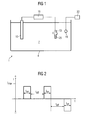
- FIG. 1 shows a device 1 according to the invention.
- the device 1 consists of a container 4, in which an electrolyte 7 is arranged.
- an electrode 10 and a component 13 is arranged in the electrolyte 7, an electrode 10 and a component 13 is arranged.
- the electrode 10 and the component 13 are electrically connected to a current / voltage pulse generator 16.
- the component 13 is, for example, a coated turbine blade, which has as a substrate a nickel- or cobalt-based superalloy on which a metallic layer is applied, which serves, for example, as a corrosion protection or anchoring layer.
- Such a layer has, in particular, the composition MCrAlY, where M represents an element iron, cobalt or nickel.
- the coating is corroded during use of the turbine blade 13.
- the resulting surface area 25 (indicated by dashed lines) is to be removed by the method according to the invention and the device 1 according to the invention.
- the current pulse generator 16 generates a pulsed current / voltage signal (FIG. 2).
- an ultrasonic probe 19 is arranged, which is operated by an ultrasonic source 22.
- the ultrasonic excitation improves the hydrodynamics of the process and thereby supports the electrochemical reaction.
- FIG. 2 shows an exemplary current / voltage curve of the current / voltage pulse generator 16.
- the current pulse signal or the voltage pulse is, for example, rectangular (pulse shape) and has a pulse duration t on . Between the individual impulses there is a break of the length t off . Furthermore, the current pulse signal is determined by its current level I max . The current flowing between the electrode 10 and the device 13 (I max ), the pulse duration (t on ) and the pulse pause (t off ) have a significant influence on the electrochemical reaction by accelerating it.
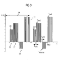
- FIG. 3 shows an example of a sequence of current pulses 40 that repeat themselves.
- a sequence 34 consists of at least two blocks 77.
- Each block 77 consists of at least one current pulse 40.
- a current pulse 40 is characterized by its duration t on , the height I max and its pulse shape (rectangle, triangle, ). Equally important as process parameters are the pauses between the individual current pulses 40 (t off ) and the pauses between the blocks 77.
- the sequence 34 consists, for example, of a first block 77 with three current pulses 40, between which in turn takes a break. This is followed by a second block 77, which has a greater current level and consists of six current pulses 40. After another pause, four current pulses 40 follow in the reverse direction, i. with changed polarity.
- sequence 34 is followed by another block 77 with four current pulses.
- the sequence 34 can be repeated several times.
- the individual pulse times t on are preferably of the order of magnitude of about 1 to 10 milliseconds.
- the duration of the block 77 is on the order of up to 10 seconds, so that up to 500 pulses are emitted in a block 77.
- a block 77 is matched with its parameters to a constituent of an alloy, which is to be stripped, for example, in order to achieve the best removal of this constituent. These can be determined in individual experiments.
Landscapes
- Chemical & Material Sciences (AREA)
- Engineering & Computer Science (AREA)
- Chemical Kinetics & Catalysis (AREA)
- Electrochemistry (AREA)
- Materials Engineering (AREA)
- Metallurgy (AREA)
- Organic Chemistry (AREA)
- Electroplating Methods And Accessories (AREA)
- Electrolytic Production Of Metals (AREA)
- Investigating Or Analyzing Materials By The Use Of Ultrasonic Waves (AREA)
Abstract
Description
Die Erfindung betrifft eine Vorrichtung und ein Verfahren zur Entfernung von Oberflächenbereichen eines Bauteils gemäß Anspruch 1 bzw. 3.The invention relates to a device and a method for removing surface areas of a component according to claim 1 or 3.
Bislang werden Bauteile, die mit Beschichtungen des Typs MCrAlY oder ZrO2 beschichtet sind, beispielsweise durch Säurestrippen in Kombination mit Sandstrahlen oder durch Hochdruckwasserstrahlen entschichtet.So far, components coated with coatings of the type MCrAlY or ZrO 2 , for example, by acid stripping in combination with sand blasting or by high-pressure water jets stripped.
Die EP 1 122 323 Al und die US 5,944,909 zeigen Beispiele für das chemische Entfernen von Oberflächenbereichen.EP 1 122 323 A1 and US 5,944,909 show examples of the chemical removal of surface areas.
Die EP 1 941 34 Al, die EP 1 010 782 Al sowie die US-PS 6,165,345 offenbaren Methoden zum elektrochemischen Entfernen von metallischen Beschichtungen (Strippen).EP 1 941 34 A1, EP 1 010 782 A1 and US Pat. No. 6,165,345 disclose methods for the electrochemical removal of metallic coatings (stripping).
Die oben aufgelisteten Verfahren sind zeit- und damit kostenintensiv.The above-listed methods are time-consuming and thus cost-intensive.
Aufgabe der Erfindung ist es daher, eine Vorrichtung und ein Verfahren aufzuzeigen, bei denen die Entschichtung schneller und preiswerter abläuft.The object of the invention is therefore to provide a device and a method in which the stripping runs faster and cheaper.
Die Aufgabe wird durch eine Vorrichtung und ein Verfahren zur Entfernung von Oberflächenbereichen eines Bauteils gemäß Anspruch 1 bzw. 3 gelöst.The object is achieved by an apparatus and a method for removing surface areas of a component according to claim 1 or 3.
Weitere vorteilhafte Ausgestaltungen und Verfahrensschritte sind in den jeweiligen Unteransprüchen aufgelistet.Further advantageous embodiments and method steps are listed in the respective subclaims.
Es zeigen
- Figur 1
- eine erfindungsgemäße Vorrichtung,
- Figur 2
- einen zeitlichen Verlauf eines Stromes eines Strompulsgebers und
- Figur 3
- einen weiteren zeitlichen Verlauf eines Stromes eines Strompulsgebers.
- FIG. 1
- a device according to the invention,
- FIG. 2
- a time course of a current of a current pulse generator and
- FIG. 3
- a further time course of a current of a current pulse generator.
Die Figur 1 zeigt eine erfindungsgemäße Vorrichtung 1.
Die Vorrichtung 1 besteht aus einem Behälter 4, in dem ein Elektrolyt 7 angeordnet ist.
In dem Elektrolyt 7 ist eine Elektrode 10 und ein Bauteil 13 angeordnet. Die Elektrode 10 und das Bauteil 13 sind elektrisch mit einem Strom/Spannungspulsgeber 16 verbunden.
Das Bauteil 13 ist beispielsweise eine beschichtete Turbinenschaufel, die als Substrat eine Nickel- oder Kobalt-basierte Superlegierung aufweist, auf der eine metallische Schicht aufgebracht ist, die beispielsweise als Korrosionsschutz- oder Verankerungsschicht dient. Eine solche Schicht weist insbesondere die Zusammensetzung MCrAlY, wobei M für ein Element Eisen, Kobalt oder Nickel steht, auf.FIG. 1 shows a device 1 according to the invention.
The device 1 consists of a
In the
The
Die Beschichtung ist während des Einsatzes der Turbinenschaufel 13 korrodiert. Der so entstandene Oberflächenbereich 25 (gestrichelt angedeutet) soll durch das erfindungsgemäße Verfahren und die erfindungsgemäße Vorrichtung 1 entfernt werden. Ebenso können von einem Bauteil 13, das keine Beschichtung aufweist, aber im oberflächennahen Bereich durch Korrosion, Oxidation oder sonstige Arten der Degradation entstandene Schichtbereiche 25 entfernt werden.
Der Strompulsgeber 16 erzeugt ein gepulstes Strom/Spannungssignal (Figur 2) .The coating is corroded during use of the
The
Optional ist in dem Elektrolyt 7 eine Ultraschallsonde 19 angeordnet, die durch eine Ultraschallquelle 22 betrieben wird.Optionally, in the
Die Ultraschallanregung verbessert die Hydrodynamik des Prozesses und unterstützt dadurch die elektrochemische Reaktion.The ultrasonic excitation improves the hydrodynamics of the process and thereby supports the electrochemical reaction.
Figur 2 zeigt einen beispielhaften Strom/Spannungsverlauf des Strom/Spannungspulsgebers 16.FIG. 2 shows an exemplary current / voltage curve of the current /
Das Strompulssignal oder der Spannungspuls ist beispielsweise rechteckig (Pulsform) und hat eine Pulsdauer ton. Zwischen den einzelnen Impulsen besteht eine Pause der Länge toff. Weiterhin wird das Strompulssignal durch seine Stromhöhe Imax bestimmt.
Der Strom, der zwischen der Elektrode 10 und dem Bauteil 13 fließt (Imax), die Pulsdauer (ton) und die Pulspause (toff) haben einen wesentlichen Einfluss auf die elektrochemische Reaktion, indem diese beschleunigt wird.The current pulse signal or the voltage pulse is, for example, rectangular (pulse shape) and has a pulse duration t on . Between the individual impulses there is a break of the length t off . Furthermore, the current pulse signal is determined by its current level I max .
The current flowing between the
Figur 3 zeigt eine beispielhafte Aneinanderreihung von Strompulsen 40, die sich wiederholen.
Eine Sequenz 34 besteht aus zumindest zwei Blöcken 77. Jeder Block 77 besteht aus zumindest einem Strompuls 40.
Ein Strompuls 40 ist charakterisiert durch seine Dauer ton, die Höhe Imax und seine Pulsform (Rechteck, Dreieck, ...). Ebenso wichtig als Prozessparameter sind die Pausen zwischen den einzelnen Strompulsen 40 (toff) und die Pausen zwischen den Blöcken 77.FIG. 3 shows an example of a sequence of
A
A
Die Sequenz 34 besteht bspw. aus einem ersten Block 77 mit drei Strompulsen 40, zwischen denen wiederum eine Pause stattfindet. Darauf folgt ein zweiter Block 77, der eine größere Stromhöhe aufweist und aus sechs Strompulsen 40 besteht. Nach einer weiteren Pause folgen vier Strompulse 40 in umgekehrter Richtung, d.h. mit geänderter Polarität.The
Als Abschluss der Sequenz 34 folgt ein weiterer Block 77 mit vier Strompulsen.
Die Sequenz 34 kann mehrfach wiederholt werden.The conclusion of the
The
Die Einzelpulszeiten ton betragen vorzugsweise größenordnungsmäßig etwa 1 bis 10 Millisekunden. Die zeitliche Dauer des Blocks 77 liegt in der Größenordnung bis zu 10 Sekunden, so dass bis zu 500 Pulse in einem Block 77 ausgesendet werden.The individual pulse times t on are preferably of the order of magnitude of about 1 to 10 milliseconds. The duration of the
Die Belegung sowohl während der Pulsabfolgen als auch in der Pausenzeit mit einem geringen Potenzial (Basisstrom) ist optional möglich.The assignment both during the pulse sequences as well as in the pause time with a low potential (base current) is optionally possible.
Ein Block 77 ist mit seinen Parametern auf ein Bestandteil einer Legierung abgestimmt, die bspw. entschichtet werden soll, um das beste Entfernen dieses Bestandteils zu erreichen. Diese können in Einzelversuchen bestimmt werden.A
Claims (10)
die einen Behälter aufweist,
in dem ein Elektrolyt angeordnet ist,
in der das Bauteil einbringbar ist,
die eine Elektrode aufweist,
wobei die Elektrode und das Bauteil elektrisch miteinander verbindbar sind und
wobei die Elektrode zumindest teilweise in dem Elektrolyten angeordnet ist,
dadurch gekennzeichnet,
dass die Vorrichtung einen elektrischen Strompulsgeber (16) aufweist,
der elektrisch zwischen Elektrode (10) und Bauteil (13) schaltbar ist und
dass der Strompulsgeber (16) Strompulse und einen Basisstrom erzeugen kann.Device for removing surface areas of a component,
which has a container,
in which an electrolyte is arranged,
in which the component is introduced,
having an electrode,
wherein the electrode and the component are electrically connectable to each other and
wherein the electrode is at least partially disposed in the electrolyte,
characterized,
in that the device has an electrical current pulse generator (16),
the electrically between the electrode (10) and component (13) is switchable and
can that the current pulse generator generating (16) current pulses and a base current.
dadurch gekennzeichnet, dass
die Vorrichtung (1) eine Ultraschallsonde (14) aufweist, die im Behälter (4) angeordnet ist, und
die vom Elektrolyten (10) umgeben ist.Device according to claim 1,
characterized in that
the device (1) comprises an ultrasonic probe (14) which is arranged in the container (4), and
which is surrounded by the electrolyte (10).
bei dem eine Elektrode
und das Bauteil in einem Elektrolyten angeordnet sind,
wobei die Elektrode und das Bauteil elektrisch leitend miteinander und mit einem Stromgeber (16) verbunden sind, und wobei der Stromgeber (16) einen gepulsten Strom oder eine gepulste Spannung erzeugt,
dadurch gekennzeichnet, dass
an dem Bauteil (13) ein positives oder ein negatives Potenzial anliegt,
um einen Basisstrom oder Basisspannung zu erzeugen.Process for removing a surface area of a component,
in which an electrode
and the component are arranged in an electrolyte,
wherein the electrode and the component are electrically conductively connected to each other and to a current generator (16), and wherein the current generator (16) generates a pulsed current or a pulsed voltage,
characterized in that
on the component (13) has a positive or a negative potential,
to generate a base current or base voltage.
dadurch gekennzeichnet, dass
in dem Elektrolyten (7) eine Ultraschallsonde (19) betrieben wird.Method according to claim 3,
characterized in that
in the electrolyte (7) an ultrasonic probe (19) is operated.
dadurch gekennzeichnet, dass
zum elektrolytischen Entschichten ein Strom/Spannungspuls (40) verwendet wird,
wobei sowohl positive als auch negative Strom/Spannungspulse (40) verwendet werden.Method according to claim 3,
characterized in that
for electrolytic stripping a current / voltage pulse (40) is used,
where both positive and negative current / voltage pulses (40) are used.
dadurch gekennzeichnet, dass
für das elektrolytische Entschichten wiederholt mehrere Strom/Spannungspulse (40) verwendet werden,
die in einer Sequenz (34) zusammengefasst sind,
wobei die Sequenz (34) von zumindest zwei verschiedenen Blöcken (77) gebildet wird,
wobei ein Block (77) aus zumindest einem Strompuls (40) besteht.Method according to claim 3,
characterized in that
for the electrolytic stripping repeated several current / voltage pulses (40) are used
which are summarized in a sequence (34),
wherein the sequence (34) is formed by at least two different blocks (77),
wherein a block (77) consists of at least one current pulse (40).
dadurch gekennzeichnet, dass
ein Block (77) bestimmt ist durch eine Anzahl von Strompulsen (40), Pulsdauer (ton), Pulspause (toff), Stromhöhe (Imax) und Pulsform.Method according to claim 6,
characterized in that
a block (77) is determined by a number of current pulses (40), pulse duration (t on ), pulse pause (t off ), current level (I max ) and pulse shape.
dadurch gekennzeichnet, dass
ein Block (77) jeweils auf einen Bestandteil einer Legierung abgestimmt ist, die entfernt werden soll,
um das Entschichten des Bestandteils der Legierung zu verstärken.Method according to claim 6,
characterized in that
a block (77) is each tuned to a constituent of an alloy which is to be removed,
to enhance the stripping of the constituent of the alloy.
dadurch gekennzeichnet, dass
eine Legierungsschicht der Art MCrAlY entschichtet wird,
wobei M ein Element der Gruppe Eisen, Kobalt oder Nickel ist.Method according to claim 3,
characterized in that
an alloy layer of the type MCrAlY is stripped,
where M is an element of the group iron, cobalt or nickel.
dadurch gekennzeichnet, dass
ein Basisstrom den Strompulsen (40) und/oder den Pausen überlagert ist.Method according to claim 6,
characterized in that
a base current is superimposed on the current pulses (40) and / or the pauses.
Applications Claiming Priority (3)
| Application Number | Priority Date | Filing Date | Title |
|---|---|---|---|
| DE10215374 | 2002-04-08 | ||
| DE10259365A DE10259365A1 (en) | 2002-04-08 | 2002-12-18 | Device and method for removing surface areas of a component |
| EP03727147A EP1507901B1 (en) | 2002-04-08 | 2003-03-21 | Device and method for removing surface areas of a component |
Related Parent Applications (1)
| Application Number | Title | Priority Date | Filing Date |
|---|---|---|---|
| EP03727147A Division EP1507901B1 (en) | 2002-04-08 | 2003-03-21 | Device and method for removing surface areas of a component |
Publications (3)
| Publication Number | Publication Date |
|---|---|
| EP1632589A2 true EP1632589A2 (en) | 2006-03-08 |
| EP1632589A3 EP1632589A3 (en) | 2006-04-05 |
| EP1632589B1 EP1632589B1 (en) | 2008-12-31 |
Family
ID=28792820
Family Applications (2)
| Application Number | Title | Priority Date | Filing Date |
|---|---|---|---|
| EP05024433A Expired - Fee Related EP1632589B1 (en) | 2002-04-08 | 2003-03-21 | Method for removing surface areas of a component |
| EP03727147A Expired - Fee Related EP1507901B1 (en) | 2002-04-08 | 2003-03-21 | Device and method for removing surface areas of a component |
Family Applications After (1)
| Application Number | Title | Priority Date | Filing Date |
|---|---|---|---|
| EP03727147A Expired - Fee Related EP1507901B1 (en) | 2002-04-08 | 2003-03-21 | Device and method for removing surface areas of a component |
Country Status (6)
| Country | Link |
|---|---|
| US (2) | US7569133B2 (en) |
| EP (2) | EP1632589B1 (en) |
| CN (1) | CN100379900C (en) |
| DE (3) | DE10259365A1 (en) |
| ES (2) | ES2292967T3 (en) |
| WO (1) | WO2003085174A2 (en) |
Cited By (1)
| Publication number | Priority date | Publication date | Assignee | Title |
|---|---|---|---|---|
| WO2008017559A1 (en) * | 2006-08-08 | 2008-02-14 | Siemens Aktiengesellschaft | Method for producing a wear layer |
Families Citing this family (20)
| Publication number | Priority date | Publication date | Assignee | Title |
|---|---|---|---|---|
| DE10259362A1 (en) * | 2002-12-18 | 2004-07-08 | Siemens Ag | Process for depositing an alloy on a substrate |
| EP1473387A1 (en) * | 2003-05-02 | 2004-11-03 | Siemens Aktiengesellschaft | Method for stripping a coating from a part |
| EP1612299B1 (en) * | 2004-06-30 | 2008-03-19 | Siemens Aktiengesellschaft | Method and apparatus for surface treatment of a component |
| EP1860210A1 (en) * | 2006-05-22 | 2007-11-28 | Siemens Aktiengesellschaft | Method for electrolytic treatment of a workpiece |
| EP1870497A1 (en) | 2006-06-23 | 2007-12-26 | Siemens Aktiengesellschaft | Method for the electrochemical stripping of a metallic coating from an element |
| DE102006044416A1 (en) * | 2006-09-18 | 2008-03-27 | Siemens Ag | Process for the electrochemical coating or stripping of components |
| FR2937054B1 (en) * | 2008-10-13 | 2010-12-10 | Commissariat Energie Atomique | METHOD AND DEVICE FOR DECONTAMINATING A METAL SURFACE |
| DE102009036221A1 (en) * | 2009-08-05 | 2011-02-17 | Extrude Hone Gmbh | Method for the electrochemical machining of a workpiece |
| EA201500017A1 (en) * | 2009-11-23 | 2015-07-30 | МЕТКОН, ЭлЭлСи | ELECTROLYTE SOLUTION AND METHOD OF ELECTROLYTIC POLISHING |
| US8580103B2 (en) | 2010-11-22 | 2013-11-12 | Metcon, Llc | Electrolyte solution and electrochemical surface modification methods |
| CN103088398B (en) * | 2011-10-31 | 2016-05-11 | 通用电气公司 | Multi-channel electrochemical removes metallic coating system and control circuit thereof |
| DE102012012419A1 (en) | 2012-06-25 | 2014-04-24 | OT Oberflächentechnik GmbH & Co. KG Schwerin | Device useful for local stripping of coated metal components, in particular coated turbine blades, comprises a brush for mechanical machining of the component to be stripped and for applying an electrolyte solution |
| JP6440814B2 (en) | 2014-03-18 | 2018-12-19 | プラティット・アクチエンゲゼルシャフト | Film removal method for ceramic hard material layer of steel and cemented carbide substrate |
| DE202014010831U1 (en) | 2014-03-18 | 2016-11-23 | Platit Ag | Holder for stripping ceramic hard coatings of steel and carbide substrates |
| US10227708B2 (en) | 2014-11-18 | 2019-03-12 | St. Jude Medical, Cardiology Division, Inc. | Systems and methods for cleaning medical device electrodes |
| CN104611759B (en) * | 2015-02-12 | 2017-03-08 | 广州市精源电子设备有限公司 | Variable Polarity pulse pickling control method |
| US10357839B1 (en) | 2015-10-08 | 2019-07-23 | The United States Of America As Represented By The Secretary Of The Army | Method for electrochemical machining using sympathetic waveform interactions |
| MD1448Z (en) * | 2019-06-25 | 2021-02-28 | Сп Завод Топаз Ао | Process for removing heat-resistant coatings from a surface of hard alloys |
| CN113106532B (en) * | 2021-04-07 | 2023-04-11 | 江苏源清动力技术有限公司 | Process for removing thermal barrier coating of thermal component of aero-engine and gas turbine |
| EP4309811A1 (en) | 2022-07-18 | 2024-01-24 | Hammann GmbH | Method for the electromechanical removal of deposits in pipelines or apparatus |
Citations (8)
| Publication number | Priority date | Publication date | Assignee | Title |
|---|---|---|---|---|
| GB190813666A (en) * | 1908-06-27 | 1908-12-31 | Alfred Levy | Process for Removing the Electrolytic Nickel or other Metallic Coating of Metallic Surfaces. |
| US2408220A (en) * | 1943-02-05 | 1946-09-24 | Westinghouse Electric Corp | Stripping of copper from zinc |
| DE1043008B (en) * | 1955-07-01 | 1958-11-06 | Othmar Ruthner | Process and device for the electrolytic removal of steel sand residues from sandblasted surfaces from metal strips |
| US4664763A (en) * | 1985-05-08 | 1987-05-12 | M&T Chemicals Inc. | Process for stripping nickel or nickel-alloy plating in a chromic acid solution |
| WO1991013191A1 (en) * | 1990-02-23 | 1991-09-05 | Gordon Roy G | Electrolytic removal of tin oxide or titanium nitride from a coater |
| WO2000017422A1 (en) * | 1998-09-18 | 2000-03-30 | Hoffman Industries International, Ltd. | Electrolytic cleaning of conductive bodies |
| EP1010782A1 (en) * | 1998-12-18 | 2000-06-21 | United Technologies Corporation | Feedback controlled electrochemical stripping of gas turbine airfoils |
| WO2000042242A1 (en) * | 1999-01-14 | 2000-07-20 | Chromalloy Gas Turbine Corporation | Electrochemical stripping of turbine blades |
Family Cites Families (17)
| Publication number | Priority date | Publication date | Assignee | Title |
|---|---|---|---|---|
| US2744860A (en) * | 1951-11-13 | 1956-05-08 | Robert H Rines | Electroplating method |
| US3616346A (en) * | 1967-03-20 | 1971-10-26 | Inoue K | Ion-control method for electrochemical machining |
| US3519543A (en) * | 1967-10-27 | 1970-07-07 | Talon Inc | Process for electrolytically cleaning and polishing electrical contacts |
| US4004992A (en) * | 1975-01-08 | 1977-01-25 | Trw Inc. | Power supply for electrochemical machining |
| US4174261A (en) * | 1976-07-16 | 1979-11-13 | Pellegrino Peter P | Apparatus for electroplating, deplating or etching |
| US4155816A (en) * | 1978-09-29 | 1979-05-22 | The Goodyear Tire & Rubber Company | Method of electroplating and treating electroplated ferrous based wire |
| GB2111530B (en) * | 1981-12-08 | 1985-07-03 | Standard Telephones Cables Ltd | Selective electro plating or etching process |
| US4466864A (en) * | 1983-12-16 | 1984-08-21 | At&T Technologies, Inc. | Methods of and apparatus for electroplating preselected surface regions of electrical articles |
| IL110297A0 (en) * | 1993-07-21 | 1994-10-21 | Dynamotive Corp | A method for removal of certain oxide films from metal surfaces |
| DE19547948C1 (en) * | 1995-12-21 | 1996-11-21 | Atotech Deutschland Gmbh | Mfg. unipolar or bipolar pulsed current for plating esp. of circuit boards at high current |
| US5944909A (en) | 1998-02-02 | 1999-08-31 | General Electric Company | Method for chemically stripping a cobalt-base substrate |
| US6402931B1 (en) * | 1998-05-18 | 2002-06-11 | Faraday Technology Marketing Group, Llc | Electrochemical machining using modulated reverse electric fields |
| US6056869A (en) * | 1998-06-04 | 2000-05-02 | International Business Machines Corporation | Wafer edge deplater for chemical mechanical polishing of substrates |
| TW533249B (en) * | 1999-09-07 | 2003-05-21 | Nat Science Council | Method and apparatus for electropolishing |
| US6352636B1 (en) | 1999-10-18 | 2002-03-05 | General Electric Company | Electrochemical system and process for stripping metallic coatings |
| US6428602B1 (en) | 2000-01-31 | 2002-08-06 | General Electric Company | Method for recovering platinum from platinum-containing coatings on gas turbine engine components |
| US6599416B2 (en) * | 2001-09-28 | 2003-07-29 | General Electric Company | Method and apparatus for selectively removing coatings from substrates |
-
2002
- 2002-12-18 DE DE10259365A patent/DE10259365A1/en not_active Withdrawn
-
2003
- 2003-03-12 US US10/511,251 patent/US7569133B2/en not_active Expired - Fee Related
- 2003-03-21 ES ES03727147T patent/ES2292967T3/en not_active Expired - Lifetime
- 2003-03-21 EP EP05024433A patent/EP1632589B1/en not_active Expired - Fee Related
- 2003-03-21 DE DE50311030T patent/DE50311030D1/en not_active Expired - Lifetime
- 2003-03-21 WO PCT/DE2003/000953 patent/WO2003085174A2/en active IP Right Grant
- 2003-03-21 EP EP03727147A patent/EP1507901B1/en not_active Expired - Fee Related
- 2003-03-21 ES ES05024433T patent/ES2317127T3/en not_active Expired - Lifetime
- 2003-03-21 CN CNB038077264A patent/CN100379900C/en not_active Expired - Fee Related
- 2003-03-21 DE DE50308417T patent/DE50308417D1/en not_active Expired - Lifetime
-
2009
- 2009-06-25 US US12/491,499 patent/US20090255828A1/en not_active Abandoned
Patent Citations (8)
| Publication number | Priority date | Publication date | Assignee | Title |
|---|---|---|---|---|
| GB190813666A (en) * | 1908-06-27 | 1908-12-31 | Alfred Levy | Process for Removing the Electrolytic Nickel or other Metallic Coating of Metallic Surfaces. |
| US2408220A (en) * | 1943-02-05 | 1946-09-24 | Westinghouse Electric Corp | Stripping of copper from zinc |
| DE1043008B (en) * | 1955-07-01 | 1958-11-06 | Othmar Ruthner | Process and device for the electrolytic removal of steel sand residues from sandblasted surfaces from metal strips |
| US4664763A (en) * | 1985-05-08 | 1987-05-12 | M&T Chemicals Inc. | Process for stripping nickel or nickel-alloy plating in a chromic acid solution |
| WO1991013191A1 (en) * | 1990-02-23 | 1991-09-05 | Gordon Roy G | Electrolytic removal of tin oxide or titanium nitride from a coater |
| WO2000017422A1 (en) * | 1998-09-18 | 2000-03-30 | Hoffman Industries International, Ltd. | Electrolytic cleaning of conductive bodies |
| EP1010782A1 (en) * | 1998-12-18 | 2000-06-21 | United Technologies Corporation | Feedback controlled electrochemical stripping of gas turbine airfoils |
| WO2000042242A1 (en) * | 1999-01-14 | 2000-07-20 | Chromalloy Gas Turbine Corporation | Electrochemical stripping of turbine blades |
Cited By (3)
| Publication number | Priority date | Publication date | Assignee | Title |
|---|---|---|---|---|
| WO2008017559A1 (en) * | 2006-08-08 | 2008-02-14 | Siemens Aktiengesellschaft | Method for producing a wear layer |
| EP1890004A1 (en) * | 2006-08-08 | 2008-02-20 | Siemens Aktiengesellschaft | Method for the production of a deposited layer from recycled layer material |
| US8673405B2 (en) | 2006-08-08 | 2014-03-18 | Siemens Aktiengesellschaft | Method for producing a wear layer |
Also Published As
| Publication number | Publication date |
|---|---|
| ES2317127T3 (en) | 2009-04-16 |
| US20090255828A1 (en) | 2009-10-15 |
| ES2292967T3 (en) | 2008-03-16 |
| EP1507901A2 (en) | 2005-02-23 |
| WO2003085174A2 (en) | 2003-10-16 |
| CN1646735A (en) | 2005-07-27 |
| DE10259365A1 (en) | 2003-10-30 |
| US7569133B2 (en) | 2009-08-04 |
| US20050224367A1 (en) | 2005-10-13 |
| DE50308417D1 (en) | 2007-11-29 |
| EP1632589A3 (en) | 2006-04-05 |
| CN100379900C (en) | 2008-04-09 |
| EP1507901B1 (en) | 2007-10-17 |
| EP1632589B1 (en) | 2008-12-31 |
| WO2003085174A3 (en) | 2004-12-23 |
| DE50311030D1 (en) | 2009-02-12 |
Similar Documents
| Publication | Publication Date | Title |
|---|---|---|
| EP1507901B1 (en) | Device and method for removing surface areas of a component | |
| AT519430A1 (en) | ELECTROCHEMICAL PULSE POLISHING | |
| DE835972C (en) | Process for the continuous electrolytic oxidation of wires, bands and similar metal objects | |
| DE3505318C2 (en) | ||
| DE102005032738B3 (en) | Electrochemical treatment of multiple workpieces comprises connecting units comprising a workpiece and a counterelectrode in series | |
| EP1743053B1 (en) | Method for production of a coating | |
| EP1573090A2 (en) | Method for the deposition of an alloy on a substrate | |
| DE59904197D1 (en) | METHOD AND DEVICE FOR PERMEATION OF BIOLOGICAL OBJECTS | |
| DE19819772A1 (en) | Method of testing corrosion resistance of object made of metal and coating | |
| EP1625244B1 (en) | Method for removing layers from a component | |
| DE3036348A1 (en) | METHOD AND DEVICE FOR CLEANING CATHODES WITH ULTRASOUND | |
| EP1590101B1 (en) | Methods and device for removing cross-linked polymers from metal structures | |
| EP0101922B1 (en) | Method and device for treating ferromagnetic materials | |
| DE10259366A1 (en) | Method for finishing a through hole of a component | |
| DE2152222A1 (en) | Process for removing gold | |
| DE132935T1 (en) | ELECTROEROSIVE MACHINING USING HYDROCARBON AND HYDROGEN LIQUIDS. | |
| DE1286311B (en) | Method and device for the identification of defects in elongated metal bodies detected by means of ultrasound | |
| DE10238593A1 (en) | Production of a semiconductor wafer from a semiconducting workpiece comprises subjecting a conducting tool as electrode to an electrical current from a direct voltage source, and applying to the workpiece in the presence of an electrolyte | |
| DE19548198A1 (en) | Method and device for repairing and / or repairing small surface damage in a large-format press plate or an endless belt made of sheet metal with a structured surface for embossing plastic-coated wood-based panels or leminate plates | |
| DE102021122584A1 (en) | Production device for the electrochemical processing of a component, in particular a turbine component, method for the electrochemical processing of a component and component | |
| DE10259360A1 (en) | Method for improving the interaction between a liquid and a component | |
| EP1535687A3 (en) | Electro-erosion method and apparatus | |
| DE10259361A1 (en) | Method and device for filling material separations on a surface | |
| WO2004054699A2 (en) | Method for improving the interaction between a medium and a structural component | |
| EP1573095A1 (en) | Method for removing at least one surface area of at least two components |
Legal Events
| Date | Code | Title | Description |
|---|---|---|---|
| PUAI | Public reference made under article 153(3) epc to a published international application that has entered the european phase |
Free format text: ORIGINAL CODE: 0009012 |
|
| PUAL | Search report despatched |
Free format text: ORIGINAL CODE: 0009013 |
|
| AC | Divisional application: reference to earlier application |
Ref document number: 1507901 Country of ref document: EP Kind code of ref document: P |
|
| AK | Designated contracting states |
Kind code of ref document: A2 Designated state(s): DE ES FR GB IT |
|
| AK | Designated contracting states |
Kind code of ref document: A3 Designated state(s): DE ES FR GB IT |
|
| 17P | Request for examination filed |
Effective date: 20060425 |
|
| AKX | Designation fees paid |
Designated state(s): DE ES FR GB IT |
|
| 17Q | First examination report despatched |
Effective date: 20061212 |
|
| GRAP | Despatch of communication of intention to grant a patent |
Free format text: ORIGINAL CODE: EPIDOSNIGR1 |
|
| RTI1 | Title (correction) |
Free format text: METHOD FOR REMOVING SURFACE AREAS OF A COMPONENT |
|
| GRAS | Grant fee paid |
Free format text: ORIGINAL CODE: EPIDOSNIGR3 |
|
| GRAA | (expected) grant |
Free format text: ORIGINAL CODE: 0009210 |
|
| AC | Divisional application: reference to earlier application |
Ref document number: 1507901 Country of ref document: EP Kind code of ref document: P |
|
| AK | Designated contracting states |
Kind code of ref document: B1 Designated state(s): DE ES FR GB IT |
|
| REG | Reference to a national code |
Ref country code: GB Ref legal event code: FG4D Free format text: NOT ENGLISH |
|
| REF | Corresponds to: |
Ref document number: 50311030 Country of ref document: DE Date of ref document: 20090212 Kind code of ref document: P |
|
| REG | Reference to a national code |
Ref country code: ES Ref legal event code: FG2A Ref document number: 2317127 Country of ref document: ES Kind code of ref document: T3 |
|
| PLBE | No opposition filed within time limit |
Free format text: ORIGINAL CODE: 0009261 |
|
| STAA | Information on the status of an ep patent application or granted ep patent |
Free format text: STATUS: NO OPPOSITION FILED WITHIN TIME LIMIT |
|
| 26N | No opposition filed |
Effective date: 20091001 |
|
| PGFP | Annual fee paid to national office [announced via postgrant information from national office to epo] |
Ref country code: FR Payment date: 20110321 Year of fee payment: 9 |
|
| PGFP | Annual fee paid to national office [announced via postgrant information from national office to epo] |
Ref country code: GB Payment date: 20110310 Year of fee payment: 9 Ref country code: ES Payment date: 20110411 Year of fee payment: 9 |
|
| PGFP | Annual fee paid to national office [announced via postgrant information from national office to epo] |
Ref country code: IT Payment date: 20110329 Year of fee payment: 9 |
|
| PG25 | Lapsed in a contracting state [announced via postgrant information from national office to epo] |
Ref country code: DE Free format text: LAPSE BECAUSE OF NON-PAYMENT OF DUE FEES Effective date: 20111001 |
|
| PGFP | Annual fee paid to national office [announced via postgrant information from national office to epo] |
Ref country code: DE Payment date: 20110520 Year of fee payment: 9 |
|
| GBPC | Gb: european patent ceased through non-payment of renewal fee |
Effective date: 20120321 |
|
| REG | Reference to a national code |
Ref country code: FR Ref legal event code: ST Effective date: 20121130 |
|
| REG | Reference to a national code |
Ref country code: DE Ref legal event code: R119 Ref document number: 50311030 Country of ref document: DE Effective date: 20121002 |
|
| PG25 | Lapsed in a contracting state [announced via postgrant information from national office to epo] |
Ref country code: GB Free format text: LAPSE BECAUSE OF NON-PAYMENT OF DUE FEES Effective date: 20120321 Ref country code: FR Free format text: LAPSE BECAUSE OF NON-PAYMENT OF DUE FEES Effective date: 20120402 |
|
| PG25 | Lapsed in a contracting state [announced via postgrant information from national office to epo] |
Ref country code: IT Free format text: LAPSE BECAUSE OF NON-PAYMENT OF DUE FEES Effective date: 20120321 |
|
| REG | Reference to a national code |
Ref country code: ES Ref legal event code: FD2A Effective date: 20131023 |
|
| PG25 | Lapsed in a contracting state [announced via postgrant information from national office to epo] |
Ref country code: ES Free format text: LAPSE BECAUSE OF NON-PAYMENT OF DUE FEES Effective date: 20120322 |