EP1469656A2 - Mobile phone having a rotational camera lens housing - Google Patents
Mobile phone having a rotational camera lens housing Download PDFInfo
- Publication number
- EP1469656A2 EP1469656A2 EP04008781A EP04008781A EP1469656A2 EP 1469656 A2 EP1469656 A2 EP 1469656A2 EP 04008781 A EP04008781 A EP 04008781A EP 04008781 A EP04008781 A EP 04008781A EP 1469656 A2 EP1469656 A2 EP 1469656A2
- Authority
- EP
- European Patent Office
- Prior art keywords
- housing
- camera lens
- hinge
- hinge axis
- mobile phone
- Prior art date
- Legal status (The legal status is an assumption and is not a legal conclusion. Google has not performed a legal analysis and makes no representation as to the accuracy of the status listed.)
- Withdrawn
Links
Images


Classifications
-
- H—ELECTRICITY
- H04—ELECTRIC COMMUNICATION TECHNIQUE
- H04N—PICTORIAL COMMUNICATION, e.g. TELEVISION
- H04N1/00—Scanning, transmission or reproduction of documents or the like, e.g. facsimile transmission; Details thereof
- H04N1/00127—Connection or combination of a still picture apparatus with another apparatus, e.g. for storage, processing or transmission of still picture signals or of information associated with a still picture
- H04N1/00281—Connection or combination of a still picture apparatus with another apparatus, e.g. for storage, processing or transmission of still picture signals or of information associated with a still picture with a telecommunication apparatus, e.g. a switched network of teleprinters for the distribution of text-based information, a selective call terminal
- H04N1/00307—Connection or combination of a still picture apparatus with another apparatus, e.g. for storage, processing or transmission of still picture signals or of information associated with a still picture with a telecommunication apparatus, e.g. a switched network of teleprinters for the distribution of text-based information, a selective call terminal with a mobile telephone apparatus
-
- H—ELECTRICITY
- H04—ELECTRIC COMMUNICATION TECHNIQUE
- H04M—TELEPHONIC COMMUNICATION
- H04M1/00—Substation equipment, e.g. for use by subscribers
- H04M1/02—Constructional features of telephone sets
- H04M1/0202—Portable telephone sets, e.g. cordless phones, mobile phones or bar type handsets
- H04M1/0206—Portable telephones comprising a plurality of mechanically joined movable body parts, e.g. hinged housings
- H04M1/0208—Portable telephones comprising a plurality of mechanically joined movable body parts, e.g. hinged housings characterized by the relative motions of the body parts
- H04M1/021—Portable telephones comprising a plurality of mechanically joined movable body parts, e.g. hinged housings characterized by the relative motions of the body parts using combined folding and rotation motions
-
- H—ELECTRICITY
- H04—ELECTRIC COMMUNICATION TECHNIQUE
- H04M—TELEPHONIC COMMUNICATION
- H04M1/00—Substation equipment, e.g. for use by subscribers
- H04M1/02—Constructional features of telephone sets
- H04M1/0202—Portable telephone sets, e.g. cordless phones, mobile phones or bar type handsets
- H04M1/026—Details of the structure or mounting of specific components
- H04M1/0264—Details of the structure or mounting of specific components for a camera module assembly
-
- H—ELECTRICITY
- H04—ELECTRIC COMMUNICATION TECHNIQUE
- H04N—PICTORIAL COMMUNICATION, e.g. TELEVISION
- H04N23/00—Cameras or camera modules comprising electronic image sensors; Control thereof
- H04N23/50—Constructional details
- H04N23/55—Optical parts specially adapted for electronic image sensors; Mounting thereof
-
- H—ELECTRICITY
- H04—ELECTRIC COMMUNICATION TECHNIQUE
- H04N—PICTORIAL COMMUNICATION, e.g. TELEVISION
- H04N23/00—Cameras or camera modules comprising electronic image sensors; Control thereof
- H04N23/57—Mechanical or electrical details of cameras or camera modules specially adapted for being embedded in other devices
-
- H—ELECTRICITY
- H04—ELECTRIC COMMUNICATION TECHNIQUE
- H04N—PICTORIAL COMMUNICATION, e.g. TELEVISION
- H04N23/00—Cameras or camera modules comprising electronic image sensors; Control thereof
- H04N23/58—Means for changing the camera field of view without moving the camera body, e.g. nutating or panning of optics or image sensors
-
- H—ELECTRICITY
- H04—ELECTRIC COMMUNICATION TECHNIQUE
- H04N—PICTORIAL COMMUNICATION, e.g. TELEVISION
- H04N7/00—Television systems
- H04N7/14—Systems for two-way working
- H04N7/141—Systems for two-way working between two video terminals, e.g. videophone
- H04N7/142—Constructional details of the terminal equipment, e.g. arrangements of the camera and the display
-
- H—ELECTRICITY
- H04—ELECTRIC COMMUNICATION TECHNIQUE
- H04M—TELEPHONIC COMMUNICATION
- H04M1/00—Substation equipment, e.g. for use by subscribers
- H04M1/02—Constructional features of telephone sets
- H04M1/0202—Portable telephone sets, e.g. cordless phones, mobile phones or bar type handsets
- H04M1/0206—Portable telephones comprising a plurality of mechanically joined movable body parts, e.g. hinged housings
- H04M1/0208—Portable telephones comprising a plurality of mechanically joined movable body parts, e.g. hinged housings characterized by the relative motions of the body parts
- H04M1/0214—Foldable telephones, i.e. with body parts pivoting to an open position around an axis parallel to the plane they define in closed position
- H04M1/0216—Foldable in one direction, i.e. using a one degree of freedom hinge
- H04M1/0218—The hinge comprising input and/or output user interface means
-
- H—ELECTRICITY
- H04—ELECTRIC COMMUNICATION TECHNIQUE
- H04M—TELEPHONIC COMMUNICATION
- H04M2250/00—Details of telephonic subscriber devices
- H04M2250/20—Details of telephonic subscriber devices including a rotatable camera
-
- H—ELECTRICITY
- H04—ELECTRIC COMMUNICATION TECHNIQUE
- H04N—PICTORIAL COMMUNICATION, e.g. TELEVISION
- H04N7/00—Television systems
- H04N7/14—Systems for two-way working
- H04N7/141—Systems for two-way working between two video terminals, e.g. videophone
- H04N7/142—Constructional details of the terminal equipment, e.g. arrangements of the camera and the display
- H04N2007/145—Handheld terminals
-
- H—ELECTRICITY
- H04—ELECTRIC COMMUNICATION TECHNIQUE
- H04N—PICTORIAL COMMUNICATION, e.g. TELEVISION
- H04N2101/00—Still video cameras
-
- H—ELECTRICITY
- H04—ELECTRIC COMMUNICATION TECHNIQUE
- H04N—PICTORIAL COMMUNICATION, e.g. TELEVISION
- H04N2201/00—Indexing scheme relating to scanning, transmission or reproduction of documents or the like, and to details thereof
- H04N2201/0008—Connection or combination of a still picture apparatus with another apparatus
- H04N2201/0063—Constructional details
Definitions
- the present invention relates generally to a mobile phone for performing audio or video communications, and in particular, to a mobile phone having a rotational camera lens housing to facilitate photographing an object.
- a mobile phone In general, a mobile phone is a device that a user carries with to communicate wirelessly with another party. For portability, the trend of the mobile phone is toward small size, lightweight, and diverse functions. Thus, future mobile phones will be small and lightweight, and used for multiple functions and purposes. They will also be modified adaptively according to a variety of multimedia or Internet environments.
- the mobile phone is an electronic device commonly used all over the world, irrespective of age and gender, and people now consider it a necessity to daily living.
- the bar-type phone has a bar-shaped single housing, the flip-type one has a flip rotatable with respect to a hinge device in a housing, and the folder-type is configured that a bar-type housing is rotatably folded by a hinge device.
- Mobile phones are also categorized into a neck wearable type or a wrist type according to the ways of carrying them. As their names imply, the neck wearable phone is worn around a neck using a string, and the wrist type is worn around a wrist.
- mobile phones are divided into a rotation type or a sliding type.
- a rotation-type mobile phone two facing housings are rotatably connected and opened/closed correspondingly.
- the sliding-type mobile phone is opened/closed by the lengthwise sliding movement of two housings.
- the mobile phones transmit video signals by adopting camera lenses.
- the existing camera lens modules are in-built or attached to the mobile phone to perform a video call or photograph an object.
- a mobile phone To photograph an object from two or more directions, a mobile phone must be equipped with as many camera lens modules. Therefore, product cost is increased.
- an object of the present invention to provide a mobile phone including a camera lens that can be exposed in three axis-directions.
- a mobile phone including a rotational camera lens housing and a camera lens assembly.
- the mobile phone includes a first housing and a second housing.
- a hinge housing rotatably connects the first housing to the second housing, a rotational camera lens housing is contained in the hinge housing, and an exposurer in the hinge housing exposes a camera lens at least twice according to the rotation of the camera lens housing.
- the mobile phone includes a first housing and a second housing.
- the second housing rotates in an advancing or receding direction to or from the first housing around a first hinge axis, facing the first housing, and turns crosswise to the first housing around a second hinge axis perpendicular to the first hinge axis.
- a hinge housing is extended along the first hinge axis between the first and second hinge housings.
- a rotational camera lens housing is rotatably contained in the hinge housing and rotates around a third hinge axis perpendicular to the first hinge axis and spaced from the second hinge axis.
- An exposurer is formed in the hinge housing and exposes a camera lens at least twice according to the rotation of the camera lens housing around the third hinge axis.
- a cylindrical camera lens hinge arm is formed at a side portion of the mobile phone, and provides a first hinge axis defined lengthwise and a third hinge axis perpendicular to the first hinge axis.
- a camera lens housing is included in the camera lens hinge arm, and rotates around the respective first and third hinge axes.
- a first control knob is rotatably engaged with an end of the camera lens hinge arm, and rotates the camera lens housing around the first hinge axis.
- a second control knob is rotatably engaged on the outer circumferential surface of the camera lens hinge arm, and rotates the camera lens housing around the third hinge axis.
- a cylindrical camera lens hinge arm is formed at a side portion of the mobile phone, and provides a first hinge axis defined lengthwise and a third hinge axis perpendicular to the first hinge axis.
- a first rotational member is engaged rotatably around the first hinge axis in the camera lens hinge arm.
- a camera lens housing is engaged with the first rotational member rotatably around the third hinge axis.
- a second rotational member is linked to the first rotational member via the camera lens housing, moves along the first hinge axis, and rotates the camera lens housing around the third hinge axis.
- the mobile phone includes a first housing and a second housing, which is connected to the first housing rotatably around a hinge axis extended in one direction.
- a hinge housing rotatably connects the first housing to the second housing.
- a rotational camera lens housing is contained in the hinge housing. The camera lens housing rotates within the hinge housing in the manner that allows photographing along the hinge axis and in a direction perpendicular to the hinge axis.
- a mobile phone includes a first housing 10, a second housing 20 rotatably connected to the first housing 10 so that the second housing 20 can recede from the first housing 10 or rotate crosswise to the first housing 10, a hinge housing 30 rotatably connecting the first and second housings 10 and 20 to each other, a rotational camera lens housing 40 contained at an end of the hinge housing 30, and an exposurer in the camera lens housing 40, for exposing a camera lens at least twice.
- An angle controller for manually adjusting the rotational angle of the camera lens housing 40 around a predetermined hinge axis is also included.
- the second housing 20 is rotatably connected to the first housing such that the second housing 20 can recede away from the facing first housing 10 or advance toward the first housing 10 around a first hinge axis A1.
- the second housing 20 can be turned crosswise to the first housing 10 around a second hinge axis A2 perpendicular to the first hinge axis A1.
- the hinge housing 30 is extended in the form of a cylinder to define the first and second hinge axes A1 and A2 and rotatably holds the camera lens housing 40 inside.
- the camera lens housing 40 is rotatable within the hinge housing 30 around a third hinge axis A3.
- the second hinge axis A2 rotates around the first hinge axis A1 and is perpendicular to the first hinge axis A1.
- the third hinge axis A3 is perpendicular to the first hinge axis A1, while it is parallel, perpendicular, or tilted to the second hinge axis A2.
- first, second and third hinge axes A1, A2, and A3 will be described in more detail with reference to FIGs. 1 to 4.
- the second hinge axis A2 when the second housing 20 is closed to the first housing 10, the second hinge axis A2 is parallel to the third hinge axis A3, while the second and third hinge axes A2 and A3 are perpendicular to the first hinge axis A1.
- the second hinge axis A2 when the second housing 20 is fully opened from the first housing 10, the second hinge axis A2 is tilted to the third hinge axis A3.
- the second hinge axis A2 is perpendicular to the third hinge axis A3, apart from each other, and also perpendicular to the first hinge axis A1.
- the first, second, and third hinge axes A1, A2, and A3 are in the same relationship as illustrated in FIG. 1.
- first and second housings 10 and 20 the hinge housing 30, and the camera lens housing 40 will be described in more detail.
- the first housing 10 has a key array 11 with a plurality of keys and a nearby microphone 12 on its top surface 10a.
- a battery pack 14 is detachably installed on the bottom surface 10b of the first housing 10.
- the second housing 20 has an auxiliary display 23 on its top surface 20a and a main display 22 on its bottom surface 20b.
- a speaker 21 is positioned near the main display 22.
- An auxiliary frame 25 is interposed between the second housing 20 and the hinge housing 30.
- the second housing 20 is connected to the auxiliary frame 25 rotatably around the second hinge axis A2.
- the auxiliary frame 25 extends in the direction of the first hinge axis A1.
- the hinge housing 30 comprises a pair of side hinge arms 31 and 32 integrally connected to the first housing 10, a center hinge arm 33 integrally connected to the second housing 20, specifically the auxiliary frame 25 between the side hinge arms 31 and 32, and a camera lens hinge arm 34 at one side of the side hinge arm 31, for containing the camera lens housing 40 therein.
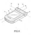
- a hinge module (not shown) is installed in the center hinge arm 33 and the auxiliary frame 25 to enable the second housing 20 to rotate around the first and second hinge axes A1 and A2. By rotating around the first and second hinge axes A1 and A2, the second housing 20 can be brought into close contact with the first housing 10 with the main display 22 exposed, as is illustrated in FIG. 6.
- the camera lens hinge arm 34 has the exposurer for exposing a camera lens (41 in FIG. 7) in the camera lens housing 40.
- the exposurer is comprised of first, second, and third openings 35, 36, and 37 formed in the camera lens hinge arm 34.
- the first opening 35 is formed on a side surface 34a of the camera lens hinge arm 34 along the first hinge axis A1.
- the second opening 36 is formed on a surface of the camera lens hinge arm 34 facing a user when the second housing 20 is closed to the first housing 10 as illustrated in FIG. 1.
- the third opening 37 is formed in a position opposite to the second opening 36 with respect to the third hinge axis A3.
- the second and third openings 36 and 37 are on the outer surface of the camera lens hinge arm 34.
- the first opening 35 is larger in diameter than the second and third openings 36 and 37.
- the second and third openings 36 and 37 of the same shape are apart from each other, symmetrically with respect to the third hinge axis A3.
- the camera lens housing 40 may be cylindrical, though it is shown as spherical.
- the camera lens housing 40 is installed to be rotatable with respect to the third hinge axis A3, having the camera lens 41 exposed from its outer circumferential surface.
- the outer circumferential surface of the camera lens housing 40 is partially exposed from the first opening 35 and the camera lens 41 can be positioned in any of the first, second, and third openings 35, 36, and 37.
- the camera lens housing 40 rotates around the third hinge axis A3 within a predetermined first angle.
- the first angle can be 180° or less. It is shown as 180°. However, if the second and third openings 36 and 37 are formed in different positions, the first angle may be changed.
- an angle controller 50 for manually controlling the camera lens housing 40 will be described below with reference to FIG. 7.
- the angle controller 50 is formed at an edge 10c of the bottom surface of the first housing 10, particularly, near the camera lens hinge arm 34.
- the angle controller 50 includes a teeth gear 51 partially protruding from a through hole formed at the edge 10c of the bottom surface of the first housing 10, and one or more gears 42 and 52 for transferring the rotational force of the teeth gear 51 to the camera lens housing 40.
- the teeth gear 51 rotates with respect to a fourth hinge axis A4 by a user's manual manipulation.
- the third hinge axis A3 and the fourth hinge axis A4 are parallel to each other.
- the second gear 52 is at en end of a rotational shaft S1 of the teeth gear 51.
- a rotational shaft S2 is extended along the third hinge axis A3 and the third gear 42 is on the rotational shaft S2.
- the second gear 52 is engaged with the third gear 42.
- the third gear 42 rotates, which in turn rotates the camera lens housing 40.
- the rotation of the camera lens housing 40 displaces the camera lens 41 coaxially with a selected one of the first, second, and third openings 35, 36, and 37. At the position, the camera lens 41 captures an object.
- a CCD Charge Coupled Device: not shown
- the FPCB is directed to the first housing 10 via a through opening 38 and the side hinge arm 32.
- a mobile phone 100 includes a first housing 101, a second housing 102, which is connected to the first housing 101 in such a manner that it can be rotated in a receding direction from the first housing 101 or turned crosswise to the first housing 101, and a camera lens assembly 200 at a portion of the mobile phone 100.
- the camera lens assembly 200 comprises a rotational camera lens housing 202 in FIG. 13, a camera lens hinge arm 201 at a portion, specifically, at an upper portion of the mobile phone 100, for holding the camera lens housing 202 therein, and exposurers 235, 213, and 217 defined on the camera lens hinge arm 201, for exposing the camera lens housing 202 at least twice.
- the camera lens assembly 200 includes angle controllers 203 and 204 for controlling the rotational angle of the camera lens housing 202 around predetermined hinge axes by user manipulation.
- a key array 111 having a plurality of keys is installed on the top surface of the first housing 101.
- a 2-way key 113 is provided on a side of the first housing 101.
- the 2-way key 113 can be used for menu selection or volume adjustment in a speech mode or standby mode. It can also provide a zoom-in/zoom-out functionality during photographing a still image or a moving picture.
- a pair of side hinge arms 115 face each other, spaced by a predetermined distance on the upper end of the first housing 101, and the camera lens hinge arm 201 is extended from one of the side hinge arms 115.
- the second housing 102 has an auxiliary display 125 on its top surface and a main display 121 on its bottom surface.
- a speaker 123 is disposed above the main display 121.
- the second housing 102 is connected to the first housing 101 in such a manner that it can be rotated face to face in a receding/advancing direction from/toward the first housing 101 and turned crosswise to the first housing 101.
- the connection is made by means of a predetermined connection member 103.
- connection member 103 has a center hinge arm 131 between the side hinge arms 115. It rotates around a first hinge axis A1 extended widthwise from the first housing 101.
- the connection member 103 also has an auxiliary frame 133 at a portion of the center hinge arm 131, thus defining a second hinge axis A2 perpendicular to the first hinge axis A1.
- An end portion of the second housing 102 is engaged with the auxiliary frame 122 to rotate around the second hinge axis A2.
- the camera lens hinge arm 201 is extended in the direction of the first hinge axis A1 from the side hinge arm 115 and contains the camera lens housing 202 therein.
- the camera lens housing 202 is rotatable around the first hinge axis A1 within the camera lens hinge arm 201. At the same time, it is rotatable around a third hinge axis A3 perpendicular to the first hinge axis A1.
- the camera lens hinge arm 201 includes the angle controllers 203 and 204 for adjusting the rotational angle of the camera lens housing 202.
- the angle controllers 203 and 204 are rotatably engaged with the camera lens hinge arm 201.
- the angle controller 203 is a first control knob for rotating the camera lens housing 202 around the first hinge axis A1.
- the angle controller 204 rotatably engaged at a predetermined position of the outer circumferential surface of the camera lens hinge arm 201, is a second knob for rotating the camera lens housing 202 around the third hinge axis A3.
- the exposurers 235, 213, and 217 are a first opening (exposurer 235) in FIG. 13 for exposing the camera lens housing 202 in a side direction of the camera lens hinge arm 201, a second opening (exposurer 213) for exposing the camera lens housing 202 in a frontal direction of the mobile phone 100, and a third opening (exposurer 217) for exposing the camera lens housing 202 in a rear direction of the mobile phone 200. That is, the camera lens housing 202 is rotated around the first, second, and third hinge axes A1, A2, and A3 within the camera lens hinge arm 201 to enable photography of a still image or a moving picture through the first, second, or third exposurer 235, 213, or 217.
- the second exposurer 213 has a pair of holes that enables a user to select a photograph angle according to the angle at which the second housing 102 is opened.
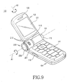
- FIGs. 9 and 10 are perspective views of the mobile phone 100 with the second housing 102 fully opened in a receding direction from the first housing 101. With the second housing 102 fully opened from the first housing 101, the main display 121 is directed toward the front of the mobile phone 100. If the user intends to photograph a still image or moving picture, he rotates the camera lens housing 202 is rotated in a manner that exposes the camera lens housing 202 through the second or third exposurer 213 or 217.
- FIGs. 11 and 12 are perspective views of the mobile phone 100 where the second housing 102 is opened at a predetermined angle from the first housing 101 and then turned crosswise to the first housing 101.
- the second housing 101 When the second housing 101 is opened at a predetermined angle, specifically about 90° or above from the first housing 101, it can rotate around the second hinge axis A2.
- the main display 121 faces in a selected one of both directions of the mobile phone 100.
- the user rotates the camera lens housing 202 in the manner that exposes the camera lens housing 202 through the first exposurer 235. With the camera lens housing 202 exposed through the first exposurer 235 and the main display 121 positioned as illustrated in FIG. 11, the user can manipulate the mobile phone 100 in the same manner as a camcorder.
- the main display 121 can be exposed outward while the second housing 102 is in close contact with the first housing 101.
- FIGs. 13 to 15 illustrate the camera lens assembly 200 for the mobile phone illustrated in FIG. 8.
- the camera lens assembly 200 comprises the camera lens hinge arm 201, the camera lens housing 202, the first and second control knobs 203 and 204, and the exposurers 235, 213, and 217.
- the camera lens hinge arm 201 is integrally formed with one side hinge arm 115 of the first housing 101 and provides a space 211 opened in a side direction of the mobile phone 100.
- the camera lens housing 202 is held in the space 211 to rotate around the first hinge axis A1 and the third hinge axis A3 perpendicular to the first hinge axis A1.
- the opened side portion of the camera lens hinge arm 201 is closed with the first control knob 203.
- the first control knob 203 rotates around the first hinge axis A1, which in turn rotates the camera lens housing 202 around the first hinge axis A1.
- the second control knob 204 is rotatably installed at a predetermined position of the outer circumferential surface of the camera lens housing 202, specifically on the third hinge axis A3.
- the second control knob 204 rotates around the third hinge axis A3, which in turn rotates the camera lens housing 202 around the third hinge axis A3.
- a pair of guide grooves 223 are formed circumferentially on the outer circumferential surface of the camera lens housing 202 to provide a rotation trajectory to the camera lens housing 202.
- the guide grooves 223 cross each other at predetermined positions and the intersections (not shown) are symmetrical with respect to the respective first and third hinge axes A1 and A3.
- the guide grooves 223 are perpendicular to each other at the intersection.
- the first and second control knobs 203 and 204 are provided with guide protrusions 233 and 243 in correspondence with the guide grooves 223.
- the first control knob 203 includes the first guide protrusion 233 which is extended in a diameter direction on its inner side surface facing the camera lens housing 202, protruding in the direction of the first hinge axis A1, for fitting into one of the guide grooves 223, and a plurality of protrusions 231 on its outer circumferential surface.
- the second control knob 204 is formed on the outer circumferential surface of the camera lens hinge arm 201 so that its inner surface faces the camera lens housing 202.
- the second guide protrusions 243 are extended in a diameter direction on the inner surface of the second control knob 204, protruding in the direction of the third hinge axis A3, for fitting into the other guide groove 223.
- the guide protrusion 233 or 243 in engagement with the guide groove 223 rotates the camera lens housing 202.
- the first or second guide protrusion 233 or 243 guides the rotation of the camera lens housing 202.
- the first guide protrusion 233 in engagement with the guide groove 223 rotates the camera lens housing 202 around the first hinge axis A1.
- the second guide protrusions 243 guide the rotation of the camera lens housing 202 because the guide groove 223 is in engagement with the second guide protrusions 243.
- a mounting groove 215a is formed to a predetermined depth from the outer circumferential surface of the camera lens hinge arm 201 and rotation holes 215b are formed in the mounting groove 215a in order to position the second guide protrusions 243 of the second control knob 204 within the space 211.
- the mounting groove 215a is centered on the third hinge axis A3, and the rotation holes 215b can be formed within a predetermined angular range with respect to rotation around the third hinge axis A3. That is, the rotation holes 215b can limit the rotational range of the second control knob 204.
- the exposurers 235, 213, and 217 are means for exposing a camera lens 221 in the camera lens housing 201 in a photograph direction. They are the first opening directed along the first hinge axis A1, the second opening directed toward the front of the mobile phone 100, and the third opening directed toward the rear of the mobile phone 100, respectively.
- the first 235 is formed through the first control knob 203 along the first hinge axis A1.
- the second exposurer 213 can be a pair of through holes spaced from each other by a predetermined distance on the outer circumferential surface of the camera lens hinge arm 201.
- the third exposurer 217 is positioned symmetrically with the second exposurer 213 on the outer circumferential surface of the camera lens hinge arm 201.
- the second and third exposurers 213 and 217 are symmetrical on the camera lens hinge arm 201 with respect to the respective hinge axes A1 and A3. Because the second exposurer 213 has the pair of adjacent through holes along the circumferential direction of the camera lens hinge arm 201, the user can photograph an object at various angles using the mobile phone 100.
- the exposurers 235, 213, and 217 are preferably sealed with transparent acryl or glass covers 291, 293, and 295.
- a tension plate 205 is fixed within the camera lens hinge arm 201 to prevent the movement of the camera lens housing 202 after rotation.
- the tension plate 205 is brought into close contact with a surface of the camera lens housing 202 by its accumulated elastic force and thus prevents the unintended movement of the camera lens housing 202.
- a stopper protrusion 225 is formed on the surface of the camera lens housing 202 facing the tension plate 205 and stopper holes 251 are formed at a predetermined interval on the tension plate 205 along the rotation trajectory of the stopper protrusion 225 to thereby stop the rotation of the camera lens housing 202 at the predetermined interval.
- the stopper protrusion 225 can be formed on the tension plate 205 and the stopper holes 251 are formed at the predetermined interval on the outer circumferential surface of the camera lens housing 202.
- the thus-constituted camera lens assembly 200 is so configured that the camera lens housing 202 can rotate within the camera lens hinge arm 201 with respect to the respective hinge axes A1 and A3. Therefore, photography can be carried out not only in various directions but also in the same manner as with a camcorder by directing the main display 121 in a side direction of the mobile phone 100.
- FIGs. 16 to 19 illustrate a camera lens assembly 300 for the mobile phone 100 illustrated in FIG. 8 according to another embodiment of the present invention.
- the camera lens assembly 300 comprises a camera lens hinge arm 301, first and second rotational members 304 and 305, a camera lens housing 302, and a control knob 303.
- the camera lens hinge arm 301 extends along the first hinge axis A1 from one side hinge arm 115, opened at one side and thus providing a space 311.
- a second opening 3 13 having a pair of through holes is formed on the outer circumferential surface of the camera lens hinge arm 301, and a third opening (not shown) is formed symmetrically with the second opening 313 with respect to the first and third hinge axes A1 and A3.
- the exposurers for the camera lens hinge arm 301 will be apparent by referring to the above-described embodiment.
- the first rotational member 304 is contained in the camera lens hinge arm 301 rotatably around the first hinge axis A1.
- One or more first link arms 341 are protruded along the first hinge axis A1 from one surface of the first rotational member 304.
- a link hole 343 is formed at an end portion of each of the first link arms 341.
- the second rotational member 305 is contained in the camera lens hinge arm 301 rotatably around the first hinge axis A1. It is linked to the first rotational member 304 in the manner that enables the second rotational member 305 to make a linear reciprocal movement along the first hinge axis A1.
- One or more second link arms 351 protrude along the first hinge axis A1 from one surface of the second rotational member 305, facing the first link arms 341.
- a link hole 353 is formed at an end portion of each of the second link arms 351. It is to be noted here that the link holes 343 or 353 are elongated in a direction in which the second rotational member 305 moves linearly, that is, in a direction perpendicular to the first hinge axis A1. Referring to FIG.
- the link holes 353 are shown elongated in the embodiment of the present invention.
- the second rotational member 305 is provided with exposing holes 355 and 357 respectively at an end portion and at a predetermined position of the outer circumferential surface.
- Guide slopes 354a and 354b are also defined on the outer circumferential surface of the second rotational member 305.
- the guide slops 354a and 354b are steep and slow respectively to an end of the second rotational member 305.
- the guide slopes 354a and 354b restrict the rotational ranges of the first and second rotational members 304 and 305, or prevent the movement of the first and second rotational members 304 and 305 away from the camera lens hinge arm 301.
- the camera lens housing 302 is like a cylinder extended along the third hinge axis A3. It has a camera lens 321 at a predetermined position of its outer circumferential surface and a pair of link protrusions 323 on both ends.
- the link protrusions 323 are selectively inserted into the link holes 343 and 353. That is, the first and second rotational members 304 and 305 are linked to each other via the camera lens housing 302 and the first and second link arms 341 and 351 are formed preferably in pairs to stabilize the link connection.
- the camera lens housing 302 rotates around the third hinge axis A3.
- the camera lens 321 is exposed from the hole 355. If the second rotational member 305 moves in an arrowed direction "a", the camera lens 321 is exposed from the hole 357. That is, as the second rotational member 305 moves linearly along the first hinge axis A1, the camera lens housing 302 rotates around the third hinge axis A3. Because the link holes 353 of the second link arms 351 are elongated, it provides room in which the link protrusions 323 move by the rotation of the camera lens housing 302.
- One or more engagement protrusion 359 is formed on the other end surface of the second rotational member 305 to be engaged with the control knob 303.
- the control knob 303 is engaged with the end of the second rotational member 305.
- the control knob 303 has a first opening 335 penetrating there through, and a plurality of protrusions 331 on its outer circumferential surface.
- the first opening 335 is used to expose the camera lens 321. That is, the camera lens 321 in the camera lens housing 302 can capture an object through one of the first, second, and third openings 335 and 313 according to user selection.
- the first, second, and third openings 335 and 313 are sealed with transparent acryl or glass covers 391, 393, and 395.
- a guide ring 397 is fit around the end of the camera lens hinge arm 301 to prevent the movement of the first and second rotational members 304 and 305 and the camera lens housing 302 away from the camera lens hinge arm 301.
- the guide ring 397 has a guide rib 397a protruding from its inner surface.
- the guide rib 397a is formed in correspondence with the guide slopes 354a and 354b formed on the outer circumferential surface of the second rotational member 305.
- the guide rib 397a restricts an excessive movement of the second rotational member 305. Also, as the second rotational member 305 rotates, the guide rib 397a moves along the slow slope 354b, moving the second rotational member 305 toward the first rotational member 304.
- a coil spring 399 is positioned within the camera lens hinge arm 301 to provide elastic force to the first rotational member 304.
- the first and second rotational members 304 and 305 and the camera lens housing 302 are rotated smoothly around the first hinge axis A1.
- the camera lens housing 302 In the camera lens assembly 300, as the second rotational member 305 moves linearly along the first hinge axis A1, the camera lens housing 302 is directed to the first or second opening 335 or 313. By rotating the control knob 303 with respect to the first hinge axis A1, the camera lens housing 302 is directed to the second opening 313 or the third opening. When the control knob 303 is rotated with the camera lens housing 302 directed to the first opening 335, the camera lens 321 is directed to the third opening by the guide rib 397a and the slow guide slope 354b.
- the mobile phone of the present invention is user-friendly and cost-effective because two or more photograph directions are available by use of one camera lens module.
Landscapes
- Engineering & Computer Science (AREA)
- Signal Processing (AREA)
- Multimedia (AREA)
- Human Computer Interaction (AREA)
- Telephone Set Structure (AREA)
- Studio Devices (AREA)
- Camera Bodies And Camera Details Or Accessories (AREA)
- Structure And Mechanism Of Cameras (AREA)
Abstract
Description
- The present invention relates generally to a mobile phone for performing audio or video communications, and in particular, to a mobile phone having a rotational camera lens housing to facilitate photographing an object.
- In general, a mobile phone is a device that a user carries with to communicate wirelessly with another party. For portability, the trend of the mobile phone is toward small size, lightweight, and diverse functions. Thus, future mobile phones will be small and lightweight, and used for multiple functions and purposes. They will also be modified adaptively according to a variety of multimedia or Internet environments. The mobile phone is an electronic device commonly used all over the world, irrespective of age and gender, and people now consider it a necessity to daily living.
- Existing mobile phones are categorized according to their looks. For example, there are a bar type, a flip type, and a folder type. The bar-type phone has a bar-shaped single housing, the flip-type one has a flip rotatable with respect to a hinge device in a housing, and the folder-type is configured that a bar-type housing is rotatably folded by a hinge device.
- Mobile phones are also categorized into a neck wearable type or a wrist type according to the ways of carrying them. As their names imply, the neck wearable phone is worn around a neck using a string, and the wrist type is worn around a wrist.
- According to their opening or closing ways, mobile phones are divided into a rotation type or a sliding type. For the rotation-type mobile phone, two facing housings are rotatably connected and opened/closed correspondingly. The sliding-type mobile phone is opened/closed by the lengthwise sliding movement of two housings. These classified mobile phones are known to those skilled in the art.
- Besides voice communications, the conventional mobile phones have been developed to further provide a high-rate data communication. Along with increasing user demands, high-rate data transmission is serviced using radio communication technology.
- Currently, the mobile phones transmit video signals by adopting camera lenses. The existing camera lens modules are in-built or attached to the mobile phone to perform a video call or photograph an object. To photograph an object from two or more directions, a mobile phone must be equipped with as many camera lens modules. Therefore, product cost is increased.
- It is, therefore, an object of the present invention to provide a mobile phone including a camera lens that can be exposed in three axis-directions.
- It is another object of the present invention to provide a cost-effective mobile phone including a single camera lens module.
- The above objects are achieved by a mobile phone including a rotational camera lens housing and a camera lens assembly.
- According to one aspect of the present invention, the mobile phone includes a first housing and a second housing. A hinge housing rotatably connects the first housing to the second housing, a rotational camera lens housing is contained in the hinge housing, and an exposurer in the hinge housing exposes a camera lens at least twice according to the rotation of the camera lens housing.
- According to another aspect of the present invention, the mobile phone includes a first housing and a second housing. The second housing rotates in an advancing or receding direction to or from the first housing around a first hinge axis, facing the first housing, and turns crosswise to the first housing around a second hinge axis perpendicular to the first hinge axis. A hinge housing is extended along the first hinge axis between the first and second hinge housings. A rotational camera lens housing is rotatably contained in the hinge housing and rotates around a third hinge axis perpendicular to the first hinge axis and spaced from the second hinge axis. An exposurer is formed in the hinge housing and exposes a camera lens at least twice according to the rotation of the camera lens housing around the third hinge axis.
- According to a further aspect of the present invention, in the camera lens assembly, a cylindrical camera lens hinge arm is formed at a side portion of the mobile phone, and provides a first hinge axis defined lengthwise and a third hinge axis perpendicular to the first hinge axis. A camera lens housing is included in the camera lens hinge arm, and rotates around the respective first and third hinge axes. A first control knob is rotatably engaged with an end of the camera lens hinge arm, and rotates the camera lens housing around the first hinge axis. A second control knob is rotatably engaged on the outer circumferential surface of the camera lens hinge arm, and rotates the camera lens housing around the third hinge axis.
- According to still another aspect of the present invention, in the camera lens assembly for a mobile phone, a cylindrical camera lens hinge arm is formed at a side portion of the mobile phone, and provides a first hinge axis defined lengthwise and a third hinge axis perpendicular to the first hinge axis. A first rotational member is engaged rotatably around the first hinge axis in the camera lens hinge arm. A camera lens housing is engaged with the first rotational member rotatably around the third hinge axis. A second rotational member is linked to the first rotational member via the camera lens housing, moves along the first hinge axis, and rotates the camera lens housing around the third hinge axis.
- According to yet another aspect of the present invention, the mobile phone includes a first housing and a second housing, which is connected to the first housing rotatably around a hinge axis extended in one direction. A hinge housing rotatably connects the first housing to the second housing. A rotational camera lens housing is contained in the hinge housing. The camera lens housing rotates within the hinge housing in the manner that allows photographing along the hinge axis and in a direction perpendicular to the hinge axis.
- The above and other objects, features, and advantages of the present invention will become more apparent from the following detailed description when taken in conjunction with the accompanying drawings in which:
- FIG. 1 is a perspective view of a mobile phone with a second housing closed to a first housing according to a preferred embodiment of the present invention;
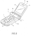
- FIG. 2 is a perspective view of the mobile phone illustrated in FIG. 1 with the second housing fully opened from the first housing around a first hinge axis;
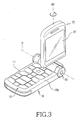
- FIG. 3 is a perspective view of the mobile phone illustrated in FIG. 1 with the second housing turned at 90° crosswise to the first housing around a second hinge axis;
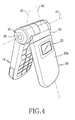
- FIG. 4 is a side perspective view of the mobile phone illustrated in FIG. 1 with the second housing slightly opened;
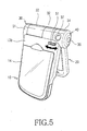
- FIG. 5 is a rear perspective view of the mobile phone illustrated in FIG. 1 with the second housing slightly opened;
- FIG. 6 is a perspective view of the mobile phone illustrated in FIG. 1 with the second housing closed to the first housing after the second housing is turned around at 180° around the second hinge axis;
- FIG. 7 is a partial cut-away rear view of a rotational camera lens housing with an angle controller for manually controlling the rotational angle of the camera lens housing, when the second housing is fully opened from the first housing in the mobile phone illustrated in FIG. 1;
- FIG. 8 is a perspective view of a mobile phone with a second housing closed to a first housing according to another preferred embodiment of the present invention;
- FIG. 9 is a perspective view of the mobile phone illustrated in FIG. 8 with the second housing fully opened from the first housing around the first hinge axis;
- FIG. 10 is a rear perspective view of the mobile phone illustrated in FIG. 8 with the second housing fully opened from the first housing around the first hinge axis;
- FIG. 11 is a perspective view of the mobile phone illustrated in FIG 8 with the second housing turned at 90° crosswise to the first housing around the second hinge axis in a first direction;
- FIG. 12 is a perspective view of the mobile phone illustrated in FIG 8 with the second housing turned at 90° crosswise to the first housing around the second hinge axis in a second direction;
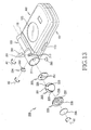
- FIG. 13 is an exploded perspective view of a camera lens assembly for the mobile phone illustrated in FIG. 8;
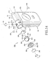
- FIG. 14 is an exploded perspective view of the camera lens assembly illustrated in FIG. 13, viewed at a different angle;
- FIG. 15 is a view depicting assembly of the camera lens assembly illustrated in FIG. 13;
- FIG. 16 is an exploded perspective view illustrating another embodiment of a camera lens assembly for the mobile phone illustrated in FIG. 8;
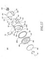
- FIG. 17 is an exploded perspective view of an enlargement of the camera lens assembly illustrated in FIG. 16;
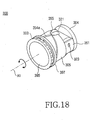
- FIG. 18 is a perspective view of the camera lens assembly illustrated in FIG. 16 in an assembled state; and
- FIG. 19 is a perspective view of a camera lens housing rotated around a third hinge axis in the camera lens assembly illustrated in FIG. 13.
-
- Preferred embodiments of the present invention will be described herein below with reference to the accompanying drawings. In the following description, well-known functions or constructions are not described in detail because they would obscure the invention in unnecessary detail.
- Referring to FIGs. 1 to 5, a mobile phone according to an embodiment of the present invention includes a
first housing 10, asecond housing 20 rotatably connected to thefirst housing 10 so that thesecond housing 20 can recede from thefirst housing 10 or rotate crosswise to thefirst housing 10, ahinge housing 30 rotatably connecting the first andsecond housings camera lens housing 40 contained at an end of thehinge housing 30, and an exposurer in thecamera lens housing 40, for exposing a camera lens at least twice. An angle controller for manually adjusting the rotational angle of thecamera lens housing 40 around a predetermined hinge axis is also included. - The
second housing 20 is rotatably connected to the first housing such that thesecond housing 20 can recede away from the facingfirst housing 10 or advance toward thefirst housing 10 around a first hinge axis A1. Thesecond housing 20 can be turned crosswise to thefirst housing 10 around a second hinge axis A2 perpendicular to the first hinge axis A1. Thehinge housing 30 is extended in the form of a cylinder to define the first and second hinge axes A1 and A2 and rotatably holds thecamera lens housing 40 inside. Thecamera lens housing 40 is rotatable within thehinge housing 30 around a third hinge axis A3. - With regard to the relationship among the first, second, and third hinge axes A1, A2, and A3, the second hinge axis A2 rotates around the first hinge axis A1 and is perpendicular to the first hinge axis A1. The third hinge axis A3 is perpendicular to the first hinge axis A1, while it is parallel, perpendicular, or tilted to the second hinge axis A2.
- The relationship among the first, second and third hinge axes A1, A2, and A3 will be described in more detail with reference to FIGs. 1 to 4. Referring to FIG. 1, when the
second housing 20 is closed to thefirst housing 10, the second hinge axis A2 is parallel to the third hinge axis A3, while the second and third hinge axes A2 and A3 are perpendicular to the first hinge axis A1. Referring to FIG. 2, when thesecond housing 20 is fully opened from thefirst housing 10, the second hinge axis A2 is tilted to the third hinge axis A3. Referring to FIG. 3, when thesecond housing 20 is opened at 90° from thefirst housing 10, the second hinge axis A2 is perpendicular to the third hinge axis A3, apart from each other, and also perpendicular to the first hinge axis A1. When the mobile phone is placed in the state illustrated in FIG. 4, the first, second, and third hinge axes A1, A2, and A3 are in the same relationship as illustrated in FIG. 1. - Hereinbelow, the structures of the first and
second housings hinge housing 30, and thecamera lens housing 40 will be described in more detail. - Referring to FIGs. 2 and 5, the
first housing 10 has akey array 11 with a plurality of keys and anearby microphone 12 on itstop surface 10a. Abattery pack 14 is detachably installed on thebottom surface 10b of thefirst housing 10. - Referring to FIGs. 2 and 4, the
second housing 20 has anauxiliary display 23 on itstop surface 20a and amain display 22 on itsbottom surface 20b. Aspeaker 21 is positioned near themain display 22. Anauxiliary frame 25 is interposed between thesecond housing 20 and thehinge housing 30. Thesecond housing 20 is connected to theauxiliary frame 25 rotatably around the second hinge axis A2. Theauxiliary frame 25 extends in the direction of the first hinge axis A1. - Referring to FIGs. 1 and 4, the
hinge housing 30 comprises a pair of side hingearms first housing 10, acenter hinge arm 33 integrally connected to thesecond housing 20, specifically theauxiliary frame 25 between the side hingearms lens hinge arm 34 at one side of theside hinge arm 31, for containing thecamera lens housing 40 therein. A hinge module (not shown) is installed in thecenter hinge arm 33 and theauxiliary frame 25 to enable thesecond housing 20 to rotate around the first and second hinge axes A1 and A2. By rotating around the first and second hinge axes A1 and A2, thesecond housing 20 can be brought into close contact with thefirst housing 10 with themain display 22 exposed, as is illustrated in FIG. 6. - The camera lens hinge
arm 34 has the exposurer for exposing a camera lens (41 in FIG. 7) in thecamera lens housing 40. The exposurer is comprised of first, second, andthird openings arm 34. Thefirst opening 35 is formed on aside surface 34a of the camera lens hingearm 34 along the first hinge axis A1. Thesecond opening 36 is formed on a surface of the camera lens hingearm 34 facing a user when thesecond housing 20 is closed to thefirst housing 10 as illustrated in FIG. 1. Thethird opening 37 is formed in a position opposite to thesecond opening 36 with respect to the third hinge axis A3. The second andthird openings arm 34. - The
first opening 35 is larger in diameter than the second andthird openings third openings - The
camera lens housing 40 may be cylindrical, though it is shown as spherical. Thecamera lens housing 40 is installed to be rotatable with respect to the third hinge axis A3, having thecamera lens 41 exposed from its outer circumferential surface. The outer circumferential surface of thecamera lens housing 40 is partially exposed from thefirst opening 35 and thecamera lens 41 can be positioned in any of the first, second, andthird openings - Preferably, the
camera lens housing 40 rotates around the third hinge axis A3 within a predetermined first angle. The first angle can be 180° or less. It is shown as 180°. However, if the second andthird openings - The structure of an
angle controller 50 for manually controlling thecamera lens housing 40 will be described below with reference to FIG. 7. In FIG. 7, theangle controller 50 is formed at anedge 10c of the bottom surface of thefirst housing 10, particularly, near the camera lens hingearm 34. - The
angle controller 50 includes ateeth gear 51 partially protruding from a through hole formed at theedge 10c of the bottom surface of thefirst housing 10, and one ormore gears camera lens housing 40. The teeth gear 51 rotates with respect to a fourth hinge axis A4 by a user's manual manipulation. The third hinge axis A3 and the fourth hinge axis A4 are parallel to each other. - Part of the teeth gear 51 protrudes outward, while its remaining part is held in the
first housing 10. Thesecond gear 52 is at en end of a rotational shaft S1 of theteeth gear 51. In thecamera lens housing 40, a rotational shaft S2 is extended along the third hinge axis A3 and thethird gear 42 is on the rotational shaft S2. Thesecond gear 52 is engaged with thethird gear 42. As theteeth gear 51 rotates, thesecond gear 52 rotates. Simultaneously, thethird gear 42 rotates, which in turn rotates thecamera lens housing 40. The rotation of thecamera lens housing 40 displaces thecamera lens 41 coaxially with a selected one of the first, second, andthird openings camera lens 41 captures an object. - A CCD (Charged Coupled Device: not shown) is installed in the
camera lens housing 40 and connected to a main board (not shown) of thefirst housing 10 by an FPCB (Flexible Printed Circuit Board). The FPCB is directed to thefirst housing 10 via a throughopening 38 and theside hinge arm 32. - Referring to FIGs. 8 to 12, a
mobile phone 100 according to another embodiment of the present invention includes afirst housing 101, asecond housing 102, which is connected to thefirst housing 101 in such a manner that it can be rotated in a receding direction from thefirst housing 101 or turned crosswise to thefirst housing 101, and acamera lens assembly 200 at a portion of themobile phone 100. Thecamera lens assembly 200 comprises a rotationalcamera lens housing 202 in FIG. 13, a cameralens hinge arm 201 at a portion, specifically, at an upper portion of themobile phone 100, for holding thecamera lens housing 202 therein, andexposurers arm 201, for exposing thecamera lens housing 202 at least twice. Further, thecamera lens assembly 200 includesangle controllers camera lens housing 202 around predetermined hinge axes by user manipulation. - A
key array 111 having a plurality of keys is installed on the top surface of thefirst housing 101. A 2-way key 113 is provided on a side of thefirst housing 101. The 2-way key 113 can be used for menu selection or volume adjustment in a speech mode or standby mode. It can also provide a zoom-in/zoom-out functionality during photographing a still image or a moving picture. A pair of side hingearms 115 face each other, spaced by a predetermined distance on the upper end of thefirst housing 101, and the camera lens hingearm 201 is extended from one of the side hingearms 115. - The
second housing 102 has anauxiliary display 125 on its top surface and amain display 121 on its bottom surface. Aspeaker 123 is disposed above themain display 121. Thesecond housing 102 is connected to thefirst housing 101 in such a manner that it can be rotated face to face in a receding/advancing direction from/toward thefirst housing 101 and turned crosswise to thefirst housing 101. The connection is made by means of apredetermined connection member 103. - The
connection member 103 has acenter hinge arm 131 between the side hingearms 115. It rotates around a first hinge axis A1 extended widthwise from thefirst housing 101. Theconnection member 103 also has anauxiliary frame 133 at a portion of thecenter hinge arm 131, thus defining a second hinge axis A2 perpendicular to the first hinge axis A1. An end portion of thesecond housing 102 is engaged with the auxiliary frame 122 to rotate around the second hinge axis A2. - The camera lens hinge
arm 201 is extended in the direction of the first hinge axis A1 from theside hinge arm 115 and contains thecamera lens housing 202 therein. Thecamera lens housing 202 is rotatable around the first hinge axis A1 within the camera lens hingearm 201. At the same time, it is rotatable around a third hinge axis A3 perpendicular to the first hinge axis A1. The camera lens hingearm 201 includes theangle controllers camera lens housing 202. Theangle controllers arm 201. Theangle controller 203 is a first control knob for rotating thecamera lens housing 202 around the first hinge axis A1. Theangle controller 204, rotatably engaged at a predetermined position of the outer circumferential surface of the camera lens hingearm 201, is a second knob for rotating thecamera lens housing 202 around the third hinge axis A3. - The
exposurers camera lens housing 202 in a side direction of the camera lens hingearm 201, a second opening (exposurer 213) for exposing thecamera lens housing 202 in a frontal direction of themobile phone 100, and a third opening (exposurer 217) for exposing thecamera lens housing 202 in a rear direction of themobile phone 200. That is, thecamera lens housing 202 is rotated around the first, second, and third hinge axes A1, A2, and A3 within the camera lens hingearm 201 to enable photography of a still image or a moving picture through the first, second, orthird exposurer second exposurer 213 has a pair of holes that enables a user to select a photograph angle according to the angle at which thesecond housing 102 is opened. - FIGs. 9 and 10 are perspective views of the
mobile phone 100 with thesecond housing 102 fully opened in a receding direction from thefirst housing 101. With thesecond housing 102 fully opened from thefirst housing 101, themain display 121 is directed toward the front of themobile phone 100. If the user intends to photograph a still image or moving picture, he rotates thecamera lens housing 202 is rotated in a manner that exposes thecamera lens housing 202 through the second orthird exposurer - FIGs. 11 and 12 are perspective views of the
mobile phone 100 where thesecond housing 102 is opened at a predetermined angle from thefirst housing 101 and then turned crosswise to thefirst housing 101. When thesecond housing 101 is opened at a predetermined angle, specifically about 90° or above from thefirst housing 101, it can rotate around the second hinge axis A2. Thus, themain display 121 faces in a selected one of both directions of themobile phone 100. In photographing a still image or moving picture, the user rotates thecamera lens housing 202 in the manner that exposes thecamera lens housing 202 through thefirst exposurer 235. With thecamera lens housing 202 exposed through thefirst exposurer 235 and themain display 121 positioned as illustrated in FIG. 11, the user can manipulate themobile phone 100 in the same manner as a camcorder. - As in the first embodiment of the present invention, since the
second housing 102 can rotate around the respective first and second hinge axes A1 and A2, themain display 121 can be exposed outward while thesecond housing 102 is in close contact with thefirst housing 101. - FIGs. 13 to 15 illustrate the
camera lens assembly 200 for the mobile phone illustrated in FIG. 8. Thecamera lens assembly 200 comprises the camera lens hingearm 201, thecamera lens housing 202, the first andsecond control knobs exposurers - The camera lens hinge
arm 201 is integrally formed with oneside hinge arm 115 of thefirst housing 101 and provides aspace 211 opened in a side direction of themobile phone 100. Thecamera lens housing 202 is held in thespace 211 to rotate around the first hinge axis A1 and the third hinge axis A3 perpendicular to the first hinge axis A1. The opened side portion of the camera lens hingearm 201 is closed with thefirst control knob 203. Thefirst control knob 203 rotates around the first hinge axis A1, which in turn rotates thecamera lens housing 202 around the first hinge axis A1. Thesecond control knob 204 is rotatably installed at a predetermined position of the outer circumferential surface of thecamera lens housing 202, specifically on the third hinge axis A3. Thesecond control knob 204 rotates around the third hinge axis A3, which in turn rotates thecamera lens housing 202 around the third hinge axis A3. - A pair of
guide grooves 223 are formed circumferentially on the outer circumferential surface of thecamera lens housing 202 to provide a rotation trajectory to thecamera lens housing 202. Theguide grooves 223 cross each other at predetermined positions and the intersections (not shown) are symmetrical with respect to the respective first and third hinge axes A1 and A3. Preferably, theguide grooves 223 are perpendicular to each other at the intersection. The first andsecond control knobs guide protrusions guide grooves 223. - The
first control knob 203 includes thefirst guide protrusion 233 which is extended in a diameter direction on its inner side surface facing thecamera lens housing 202, protruding in the direction of the first hinge axis A1, for fitting into one of theguide grooves 223, and a plurality ofprotrusions 231 on its outer circumferential surface. Thesecond control knob 204 is formed on the outer circumferential surface of the camera lens hingearm 201 so that its inner surface faces thecamera lens housing 202. Thesecond guide protrusions 243 are extended in a diameter direction on the inner surface of thesecond control knob 204, protruding in the direction of the third hinge axis A3, for fitting into theother guide groove 223. - When the user rotates the first or
second control knob guide protrusion guide groove 223 rotates thecamera lens housing 202. In turn, the first orsecond guide protrusion camera lens housing 202. - For example, if the user rotates the
first control knob 203, thefirst guide protrusion 233 in engagement with theguide groove 223 rotates thecamera lens housing 202 around the first hinge axis A1. At the same time, thesecond guide protrusions 243 guide the rotation of thecamera lens housing 202 because theguide groove 223 is in engagement with thesecond guide protrusions 243. - To install the
second control knob 204, a mountinggroove 215a is formed to a predetermined depth from the outer circumferential surface of the camera lens hingearm 201 androtation holes 215b are formed in the mountinggroove 215a in order to position thesecond guide protrusions 243 of thesecond control knob 204 within thespace 211. The mountinggroove 215a is centered on the third hinge axis A3, and the rotation holes 215b can be formed within a predetermined angular range with respect to rotation around the third hinge axis A3. That is, the rotation holes 215b can limit the rotational range of thesecond control knob 204. - The
exposurers camera lens 221 in thecamera lens housing 201 in a photograph direction. They are the first opening directed along the first hinge axis A1, the second opening directed toward the front of themobile phone 100, and the third opening directed toward the rear of themobile phone 100, respectively. The first 235 is formed through thefirst control knob 203 along the first hinge axis A1. Thesecond exposurer 213 can be a pair of through holes spaced from each other by a predetermined distance on the outer circumferential surface of the camera lens hingearm 201. Thethird exposurer 217 is positioned symmetrically with thesecond exposurer 213 on the outer circumferential surface of the camera lens hingearm 201. That is, the second and third exposurers 213 and 217 are symmetrical on the camera lens hingearm 201 with respect to the respective hinge axes A1 and A3. Because thesecond exposurer 213 has the pair of adjacent through holes along the circumferential direction of the camera lens hingearm 201, the user can photograph an object at various angles using themobile phone 100. Theexposurers - A
tension plate 205 is fixed within the camera lens hingearm 201 to prevent the movement of thecamera lens housing 202 after rotation. Thetension plate 205 is brought into close contact with a surface of thecamera lens housing 202 by its accumulated elastic force and thus prevents the unintended movement of thecamera lens housing 202. Astopper protrusion 225 is formed on the surface of thecamera lens housing 202 facing thetension plate 205 andstopper holes 251 are formed at a predetermined interval on thetension plate 205 along the rotation trajectory of thestopper protrusion 225 to thereby stop the rotation of thecamera lens housing 202 at the predetermined interval. Thestopper protrusion 225 can be formed on thetension plate 205 and the stopper holes 251 are formed at the predetermined interval on the outer circumferential surface of thecamera lens housing 202. - The thus-constituted
camera lens assembly 200 is so configured that thecamera lens housing 202 can rotate within the camera lens hingearm 201 with respect to the respective hinge axes A1 and A3. Therefore, photography can be carried out not only in various directions but also in the same manner as with a camcorder by directing themain display 121 in a side direction of themobile phone 100. - FIGs. 16 to 19 illustrate a
camera lens assembly 300 for themobile phone 100 illustrated in FIG. 8 according to another embodiment of the present invention. As illustrated, thecamera lens assembly 300 comprises a cameralens hinge arm 301, first and secondrotational members camera lens housing 302, and acontrol knob 303. - The camera lens hinge
arm 301 extends along the first hinge axis A1 from oneside hinge arm 115, opened at one side and thus providing aspace 311. A second opening 3 13 having a pair of through holes is formed on the outer circumferential surface of the camera lens hingearm 301, and a third opening (not shown) is formed symmetrically with thesecond opening 313 with respect to the first and third hinge axes A1 and A3. The exposurers for the camera lens hingearm 301 will be apparent by referring to the above-described embodiment. - The first
rotational member 304 is contained in the camera lens hingearm 301 rotatably around the first hinge axis A1. One or morefirst link arms 341 are protruded along the first hinge axis A1 from one surface of the firstrotational member 304. Alink hole 343 is formed at an end portion of each of thefirst link arms 341. - The second
rotational member 305 is contained in the camera lens hingearm 301 rotatably around the first hinge axis A1. It is linked to the firstrotational member 304 in the manner that enables the secondrotational member 305 to make a linear reciprocal movement along the first hinge axis A1. One or moresecond link arms 351 protrude along the first hinge axis A1 from one surface of the secondrotational member 305, facing thefirst link arms 341. Alink hole 353 is formed at an end portion of each of thesecond link arms 351. It is to be noted here that the link holes 343 or 353 are elongated in a direction in which the secondrotational member 305 moves linearly, that is, in a direction perpendicular to the first hinge axis A1. Referring to FIG. 17, the link holes 353 are shown elongated in the embodiment of the present invention. To expose thecamera lens 321 in thecamera lens housing 302, the secondrotational member 305 is provided with exposingholes -
Guide slopes rotational member 305. The guide slops 354a and 354b are steep and slow respectively to an end of the secondrotational member 305. As described later in more detail, the guide slopes 354a and 354b restrict the rotational ranges of the first and secondrotational members rotational members arm 301. - The
camera lens housing 302 is like a cylinder extended along the third hinge axis A3. It has acamera lens 321 at a predetermined position of its outer circumferential surface and a pair oflink protrusions 323 on both ends. The link protrusions 323 are selectively inserted into the link holes 343 and 353. That is, the first and secondrotational members camera lens housing 302 and the first andsecond link arms - Accordingly, as the second
rotational member 305 moves linearly along the first hinge axis A1, thecamera lens housing 302 rotates around the third hinge axis A3. Referring to FIGs. 18 and 19, with the first and secondrotational members camera lens 321 is exposed from thehole 355. If the secondrotational member 305 moves in an arrowed direction "a", thecamera lens 321 is exposed from thehole 357. That is, as the secondrotational member 305 moves linearly along the first hinge axis A1, thecamera lens housing 302 rotates around the third hinge axis A3. Because the link holes 353 of thesecond link arms 351 are elongated, it provides room in which thelink protrusions 323 move by the rotation of thecamera lens housing 302. - One or
more engagement protrusion 359 is formed on the other end surface of the secondrotational member 305 to be engaged with thecontrol knob 303. - The
control knob 303 is engaged with the end of the secondrotational member 305. Thecontrol knob 303 has afirst opening 335 penetrating there through, and a plurality ofprotrusions 331 on its outer circumferential surface. Thefirst opening 335 is used to expose thecamera lens 321. That is, thecamera lens 321 in thecamera lens housing 302 can capture an object through one of the first, second, andthird openings third openings - A
guide ring 397 is fit around the end of the camera lens hingearm 301 to prevent the movement of the first and secondrotational members camera lens housing 302 away from the camera lens hingearm 301. Theguide ring 397 has aguide rib 397a protruding from its inner surface. Theguide rib 397a is formed in correspondence with the guide slopes 354a and 354b formed on the outer circumferential surface of the secondrotational member 305. - As illustrated in FIG. 19, as the second
rotational member 305 moves linearly along the first hinge axis A1, theguide rib 397a restricts an excessive movement of the secondrotational member 305. Also, as the secondrotational member 305 rotates, theguide rib 397a moves along theslow slope 354b, moving the secondrotational member 305 toward the firstrotational member 304. - A
coil spring 399 is positioned within the camera lens hingearm 301 to provide elastic force to the firstrotational member 304. Thus, the first and secondrotational members camera lens housing 302 are rotated smoothly around the first hinge axis A1. - In the
camera lens assembly 300, as the secondrotational member 305 moves linearly along the first hinge axis A1, thecamera lens housing 302 is directed to the first orsecond opening control knob 303 with respect to the first hinge axis A1, thecamera lens housing 302 is directed to thesecond opening 313 or the third opening. When thecontrol knob 303 is rotated with thecamera lens housing 302 directed to thefirst opening 335, thecamera lens 321 is directed to the third opening by theguide rib 397a and theslow guide slope 354b. - As described above, the mobile phone of the present invention is user-friendly and cost-effective because two or more photograph directions are available by use of one camera lens module.
- While the present invention has been shown and described with reference to certain preferred embodiments thereof, it will be understood by those skilled in the art that various changes in form and details may be made therein without departing from the spirit and scope of the invention as defined by the appended claims.
Claims (34)
- A mobile phone comprising:a first housing;a second housing;a hinge housing for rotatably connecting the first housing to the second housing;a rotational camera lens housing contained in the hinge housing, andan exposurer formed in the hinge housing, for exposing a camera lens in a plurality of positions according to the rotation of the camera lens housing.
- The mobile phone of claim 1, characterized by said second housing for rotating in an advancing and receding direction to and from the first housing around a first hinge axis, facing the first housing, and turning cross wise to the first housing around a second hinge axis, which is perpendicular to the first hinge axis;
said hinge housing extending along the first hinge axis between the first and second housing; and
said rotational camera lens contained in the hinge housing for rotating around the third hinge axis perpendicular to the first hinge axis and spaced a predetermined distance from the second hinge axis. - The mobile phone according to claim 1 or 2, wherein the exposurer comprises:a first opening formed on a first side surface of the hinge housing;a second opening formed on an outer circumferential surface of the hinge housing; anda third opening spaced a predetermined distance from the second opening.
- The mobile phone according to claim 3, wherein the second opening is spaced a predetermined distance from the third hinge axis.
- The mobile phone according to claim 3 or 4, wherein the first opening is larger than the second and third openings, and the second and third openings are identical in shape.
- The mobile phone according to one of the previous claims,
characterized by an angle controller for manually controlling a rotational angle of the camera lens housing. - The mobile phone according to claim 6, wherein the angle controller is formed on an edge of a bottom surface of the first housing, adjacent to the camera lens housing.
- The mobile phone according to claim 6 or 7, wherein the angle controller comprises:a teeth gear partially protruding from an edge of the first housing, for rotating with respect to a hinge axis parallel to a hinge axis of the camera lens housing; andat least one gear installed in the hinge housing, for transferring rotational force of the teeth gear to the camera lens housing.
- The mobile phone according to one of the previous claims, wherein the camera lens housing is spherical in shape.
- The mobile phone according to one of the previous claims, wherein the first housing comprises:a key array including a plurality of keys arranged on a top surface of the first housing;a microphone; anda battery pack attached to a bottom surface of the first housing.
- The mobile phone according to one of the previous claims, wherein the second housing comprises:an auxiliary display on a top surface of the second housing;a main display on a bottom surface of the second housing; and a speaker.
- The mobile phone according to one of the previous claims, wherein the hinge housing comprises:a pair of side hinge arms integrally formed with the first housing; a center hinge arm between the side hinge arms, integrally formed with the second housing; anda camera lens hinge arm formed along a hinge axis of the side hinge arms.
- The mobile phone according to one of the previous claims, wherein the camera lens housing is contained in the hinge housing to be rotatable within a predetermined first angle around a predetermined rotational axis.
- The mobile phone according to claim 13, wherein the predetermined first angle is 180°.
- The mobile phone according to one of the previous claims, wherein when the second housing is closed to the first housing, the second hinge axis is parallel to the third hinge axis, when the second housing is fully opened from the first housing, the second hinge axis is tilted to the third hinge axis, and when the second housing is opened at 90° from the first housing, the second hinge axis is perpendicular to the third hinge axis.
- The mobile phone according to one of the previous claims, wherein the second hinge axis rotates around the first hinge axis and is perpendicular to the first hinge axis, and the third hinge axis is one of parallel, perpendicular, and tilted to the second hinge axis.
- The mobile phone according to claim 13, wherein the angle is between 90° and 180°.
- The mobile phone according to claim 7, wherein the angle controller comprises:a teeth gear partially protruding from an edge of the first housing, for rotating around a fourth hinge axis parallel to the third hinge axis of the camera lens housing; and at least one gear installed in the first housing, for transferring a rotational force of the teeth gear to the camera lens housing.
- A camera lens assembly for a mobile phone, comprising:a cylindrical camera lens hinge arm at a side portion of the mobile phone, for providing a first hinge axis defined lengthwise and a third hinge axis perpendicular to the first hinge axis;a camera lens housing contained in the camera lens hinge arm, for rotating around the first and third hinge axes;a first control knob rotatably engaged with an end of the camera lens hinge arm, for rotating the camera lens housing around the first hinge axis; anda second control knob rotatably engaged on an outer circumferential surface of the camera lens hinge arm, for rotating the camera lens housing around the third hinge axis.
- The camera lens assembly of claim 19, wherein the first control knob is positioned on the first hinge axis and rotates around the first hinge axis, and the second control knob is positioned on the third hinge axis and rotates around the third hinge axis.
- The camera lens assembly of claim 19, wherein the first control knob has a first opening penetrating along the first hinge axis.
- The camera lens assembly of claim 19, wherein the camera lens hinge arm comprises a pair of second openings adjacently positioned on an outer circumferential surface of the camera lens hinge arm, and a third opening opposite to the second openings with respect to the third hinge axis.
- The camera lens assembly of claim 19, further comprising:a pair of guide grooves formed circumferentially on the outer circumferential surface of the camera lens housing to provide a rotation trajectory to the camera lens housing, and crossing each other at predetermined positions, the intersections of the guide grooves being symmetrical with respect to the respective first and third hinge axes;a first guide protrusion protruding along the first hinge axis from an inner surface of the first control knob and fit into one of the guide grooves; anda second guide protrusion protruding along the third hinge axis from the inner surface of the second control knob and fit into the other guide groove.
- The camera lens assembly of claim 23, further comprising:wherein the second control knob is symmetrical with respect to the third hinge axis and the rotation hole is formed within a predetermined angular range with respect to the rotation of the second control knob around the third hinge axis.a mounting groove sunk from the outer circumferential surface of the camera lens hinge arm; anda rotation hole formed in the mounting groove, in correspondence with the second guide protrusion, for protruding the second guide protrusion inward the camera lens hinge arm,
- The camera lens assembly of claim 19, further comprising:a stopper protrusion protruding along the first hinge axis from a surface of the camera lens housing, spaced a predetermined distance from the first hinge axis;a tension plate fixed within the camera lens hinge arm, facing the camera lens housing, and brought into close contact with the camera lens housing by elastic force; andat least one stopper hole formed on the tension plate along a rotation trajectory of the stopper protrusion.
- A camera lens assembly for a mobile phone, comprising:a cylindrical camera lens hinge arm at a side portion of the mobile phone, for providing a first hinge axis defined lengthwise and a third hinge axis perpendicular to the first hinge axis;a first rotational member engaged rotatably around the first hinge axis in the camera lens hinge arm;a camera lens housing engaged with the first rotational member rotatably around the third hinge axis; anda second rotational member linked to the first rotational member via the camera lens housing, for moving along the first hinge axis and rotating the camera lens housing around the third hinge axis.
- The camera lens assembly of claim 26, further comprising:at least one first link arm extended along the first hinge axis from the first rotational member;at least one second link arm extended along the first hinge axis from the second rotational member, facing the first link arm; andat least one pair of link protrusions formed on the camera lens housing and rotatably engaged with ends of the first and second link arms.
- The camera lens assembly of claim 27, wherein the camera lens housing is cylindrical and includes a pair of link protrusions at each of both ends of the camera lens housing.
- The camera lens assembly of claim 27, further comprising a pair of first link arms and a pair of second link arms and link holes are formed on ends of the first and second link arms, in correspondence with the link protrusions.
- The camera lens assembly of claim 29, wherein the link holes on the ends of the second link arms are elongated in a direction perpendicular to the first hinge axis.
- The camera lens assembly of claim 26, wherein the second rotational member comprises an exposing opening formed along the first hinge axis.
- The camera lens assembly of claim 26, further comprising a knob engaged with an end of the second rotational member, for rotating the first rotational member, the camera lens housing, and the second rotational member around the first hinge axis.
- The camera lens assembly of claim 26, wherein the camera lens hinge arm comprises a pair of second openings adjacently positioned on the outer circumferential surface of the camera lens hinge arm, and a first opening opposite to the second openings with respect to the third hinge axis.
- A mobile phone comprising:wherein the camera lens housing rotates within the hinge housing to enable photographing along the hinge axis and in a direction perpendicular to the hinge axis.a first housing;a second housing connected to the first housing rotatably around a hinge axis extended in one direction;a hinge housing for rotatably connecting the first housing to the second housing; anda rotational camera lens housing contained in the hinge housing,
Applications Claiming Priority (4)
| Application Number | Priority Date | Filing Date | Title |
|---|---|---|---|
| KR20030023301 | 2003-04-14 | ||
| KR2003023301 | 2003-04-14 | ||
| KR2003056031 | 2003-08-13 | ||
| KR1020030056031A KR100557065B1 (en) | 2003-04-14 | 2003-08-13 | Mobile phone with rotational camera lens housing |
Publications (2)
| Publication Number | Publication Date |
|---|---|
| EP1469656A2 true EP1469656A2 (en) | 2004-10-20 |
| EP1469656A3 EP1469656A3 (en) | 2006-02-01 |
Family
ID=32911525
Family Applications (1)
| Application Number | Title | Priority Date | Filing Date |
|---|---|---|---|
| EP04008781A Withdrawn EP1469656A3 (en) | 2003-04-14 | 2004-04-13 | Mobile phone having a rotational camera lens housing |
Country Status (4)
| Country | Link |
|---|---|
| US (1) | US20040203535A1 (en) |
| EP (1) | EP1469656A3 (en) |
| JP (1) | JP4188867B2 (en) |
| CN (1) | CN100409649C (en) |
Cited By (5)
| Publication number | Priority date | Publication date | Assignee | Title |
|---|---|---|---|---|
| EP1511312A1 (en) * | 2003-08-21 | 2005-03-02 | Samsung Electronics Co., Ltd. | Cameralens assembly for portable wireless terminals |
| WO2006006023A1 (en) * | 2004-06-29 | 2006-01-19 | Nokia Corporation | A mobile terminal concept with a slide and twist mechanism |
| WO2006079694A1 (en) * | 2005-01-31 | 2006-08-03 | Elcoteq Se | Mobile communications device |
| US8073502B2 (en) | 2005-03-18 | 2011-12-06 | Sony Ericsson Mobile Communications Ab | Hinged portable radio communication equipment with a double action hinge |
| EP3984826A1 (en) * | 2020-10-19 | 2022-04-20 | Veoneer Sweden AB | Driver monitoring system and method for manufacturing a driver monitoring system |
Families Citing this family (55)
| Publication number | Priority date | Publication date | Assignee | Title |
|---|---|---|---|---|
| US7155266B2 (en) * | 2004-04-21 | 2006-12-26 | Nokia Corporation | Hinge for fold phone |
| US7426406B2 (en) * | 2003-04-23 | 2008-09-16 | Nokia Corporation | Mobile communications device with synchronising hinge |
| US7512426B2 (en) * | 2003-04-23 | 2009-03-31 | Nokia Corporation | Mobile communications device with synchronising hinge |
| US20060034601A1 (en) * | 2003-04-23 | 2006-02-16 | Tage Andersson | Multi-function two panel electronic device with 360° relative motion |
| TW588902U (en) * | 2003-04-25 | 2004-05-21 | Hon Hai Prec Ind Co Ltd | Lens module for a communication unit |
| KR100739564B1 (en) * | 2003-07-31 | 2007-07-16 | 엘지전자 주식회사 | A Camera Mounted Mobile Phone |
| JP2005054890A (en) * | 2003-08-04 | 2005-03-03 | Kato Electrical Mach Co Ltd | Hinge for portable terminal |
| JP4048435B2 (en) * | 2003-10-23 | 2008-02-20 | ソニー株式会社 | Electronics |
| KR100617688B1 (en) * | 2004-05-19 | 2006-08-28 | 삼성전자주식회사 | Hinge apparatus for mobile phone |
| JP4778207B2 (en) * | 2004-06-08 | 2011-09-21 | 日本電気株式会社 | HINGE MECHANISM, ELECTRONIC DEVICE INCLUDING THE HINGE MECHANISM, AND METHOD FOR ASSEMBLING THE SAME |
| US20060023411A1 (en) * | 2004-07-27 | 2006-02-02 | Samsung Electronics Co., Ltd. | Swing hinge apparatus and portable terminal with the same |
| KR100606073B1 (en) * | 2004-10-25 | 2006-07-28 | 삼성전자주식회사 | Portable communication device |
| KR100735266B1 (en) * | 2004-10-26 | 2007-07-03 | 삼성전자주식회사 | Mobile phone for multimedia |
| JP2006135385A (en) * | 2004-11-02 | 2006-05-25 | Canon Inc | Camera |
| US7565183B2 (en) * | 2004-11-15 | 2009-07-21 | Sony Ericsson Mobile Communications Ab | Mobile device with selectable camera position |
| TWM268831U (en) | 2004-11-19 | 2005-06-21 | Lite On Technology Corp | Portable electronic apparatus |
| TWM269695U (en) * | 2004-12-22 | 2005-07-01 | Lite On Technology Corp | Hand-held-type electronic data processor |
| KR100689472B1 (en) * | 2005-01-11 | 2007-03-08 | 삼성전자주식회사 | Portable communication device |
| KR100630068B1 (en) * | 2005-01-25 | 2006-09-27 | 삼성전자주식회사 | Hinge device for display rotation type mobile phone |
| US7528885B2 (en) * | 2005-02-07 | 2009-05-05 | Ensky Technology Co., Ltd. | Portable electronic device with lens rotation positioning structure |
| USD524785S1 (en) * | 2005-02-07 | 2006-07-11 | Li Huang | Mobile-phone thermal imager |
| CN100559839C (en) * | 2005-03-30 | 2009-11-11 | 皇家飞利浦电子股份有限公司 | Portable electron device with rotary camera unit |
| US7414834B2 (en) * | 2005-04-21 | 2008-08-19 | Nokia Corporation | Mobile communications device with synchronising hinge |
| KR100901860B1 (en) * | 2005-06-15 | 2009-06-09 | (주)케이티에프테크놀로지스 | Mobile communication termimal |
| US20070060216A1 (en) * | 2005-09-12 | 2007-03-15 | Cheng-Wen Huang | Portable communication apparatus |
| TWI276340B (en) * | 2005-09-16 | 2007-03-11 | Asustek Comp Inc | Electronic device having a housing capable of being rotated horizontally and moved vertically |
| EP1768387B1 (en) * | 2005-09-22 | 2014-11-05 | Samsung Electronics Co., Ltd. | Image capturing apparatus with image compensation and method therefor |
| US20070071438A1 (en) * | 2005-09-27 | 2007-03-29 | Universal Scientific Industrial Co., Ltd. | Handheld electronic device including a rotatable camera unit |
| KR100728926B1 (en) * | 2006-03-20 | 2007-06-15 | 삼성전자주식회사 | Electronic machine having 3 axis hinge structure |
| US20080058008A1 (en) * | 2006-08-02 | 2008-03-06 | Jae-Woong Yoon | Mobile telecommunication apparatus with a built-in camera and the camera therein |
| TWI386009B (en) * | 2007-01-22 | 2013-02-11 | Hon Hai Prec Ind Co Ltd | A portable electronic device having a function for photo-taking |
| JP4586175B2 (en) * | 2007-10-15 | 2010-11-24 | Necカシオモバイルコミュニケーションズ株式会社 | Terminal device |
| US9003315B2 (en) | 2008-04-01 | 2015-04-07 | Litl Llc | System and method for streamlining user interaction with electronic content |
| US20090322790A1 (en) * | 2008-04-01 | 2009-12-31 | Yves Behar | System and method for streamlining user interaction with electronic content |
| US8624844B2 (en) | 2008-04-01 | 2014-01-07 | Litl Llc | Portable computer with multiple display configurations |
| US8612888B2 (en) * | 2008-04-01 | 2013-12-17 | Litl, Llc | Method and apparatus for managing digital media content |
| US8577957B2 (en) * | 2008-04-01 | 2013-11-05 | Litl Llc | System and method for streamlining user interaction with electronic content |
| CN101750698A (en) | 2008-12-10 | 2010-06-23 | 深圳富泰宏精密工业有限公司 | Lens module and electronic device applying lens module |
| CN101750853B (en) * | 2008-12-17 | 2012-10-10 | 鸿富锦精密工业(深圳)有限公司 | Electronic device and image-getting module |
| US8938753B2 (en) | 2010-05-12 | 2015-01-20 | Litl Llc | Configurable computer system |
| US9436219B2 (en) | 2010-05-12 | 2016-09-06 | Litl Llc | Remote control to operate computer system |
| USD669587S1 (en) * | 2010-09-06 | 2012-10-23 | FotoFinder Systems GmbH | External lens for cell phones |
| JP2012119851A (en) * | 2010-11-30 | 2012-06-21 | Brother Ind Ltd | Terminal apparatus |
| KR101390392B1 (en) * | 2011-11-24 | 2014-04-30 | 안성기 | Case for digital assistants of keyboard type |
| EP2610856A1 (en) * | 2011-12-29 | 2013-07-03 | Samsung Electronics Co., Ltd | Display device |
| CN102905062B (en) * | 2012-10-17 | 2015-12-09 | 歌尔声学股份有限公司 | The implementation method of a kind of built-in camera and built-in camera |
| KR20140145301A (en) * | 2013-06-13 | 2014-12-23 | 삼성전자주식회사 | Method for performing a function while being on the call mode and portable electronic device implementing the same |
| US9122455B2 (en) * | 2013-11-22 | 2015-09-01 | Dell Products L.P. | Information handling system housing lid with synchronized motion provided by unequal gears |
| US20150185704A1 (en) * | 2013-12-30 | 2015-07-02 | Tau-Jeng Hsu | Electronic watch structure capable of selectively mounting a camera lens |
| WO2015143694A1 (en) * | 2014-03-28 | 2015-10-01 | Intel Corporation | Rotation sensor device |
| USD816666S1 (en) | 2015-10-30 | 2018-05-01 | Lenovo (Beijing) Co., Ltd. | Tablet computer |
| CN105704356A (en) * | 2016-03-25 | 2016-06-22 | 北京亮亮视野科技有限公司 | Multi-freedom image photographing system applied on wearable device |
| US10955268B2 (en) * | 2018-08-20 | 2021-03-23 | Ford Global Technologies, Llc | Methods and apparatus to facilitate active protection of peripheral sensors |
| CN209105228U (en) * | 2018-10-31 | 2019-07-12 | Oppo广东移动通信有限公司 | Folding mobile terminal |
| TWI789562B (en) * | 2019-06-04 | 2023-01-11 | 仁寶電腦工業股份有限公司 | Electronic device |
Citations (4)
| Publication number | Priority date | Publication date | Assignee | Title |
|---|---|---|---|---|
| US20010004269A1 (en) * | 1999-12-14 | 2001-06-21 | Junichiro Shibata | Portable terminal |
| US20010036845A1 (en) * | 2000-01-10 | 2001-11-01 | Jun-Sang Park | Radiotelephone for visual communication |
| EP1267576A2 (en) * | 2001-06-12 | 2002-12-18 | Lg Electronics Inc. | Portable phone with camera |
| US20030044001A1 (en) * | 2001-09-06 | 2003-03-06 | Samsung Electronics Co., Ltd. | Apparatus for mounting a rotational lens housing in a folder-type telephone |
Family Cites Families (10)
| Publication number | Priority date | Publication date | Assignee | Title |
|---|---|---|---|---|
| US6639625B1 (en) * | 1997-07-16 | 2003-10-28 | Minolta Co., Ltd. | Image sensing device |
| JP2000253124A (en) * | 1999-03-01 | 2000-09-14 | Matsushita Electric Ind Co Ltd | Information portable terminal provided with image- pickup function |
| JP2001094840A (en) * | 1999-09-27 | 2001-04-06 | Matsushita Electric Ind Co Ltd | Monitoring camera device |
| JP2001352380A (en) * | 2000-06-08 | 2001-12-21 | Minolta Co Ltd | Mobile terminal |
| US6532035B1 (en) * | 2000-06-29 | 2003-03-11 | Nokia Mobile Phones Ltd. | Method and apparatus for implementation of close-up imaging capability in a mobile imaging system |
| JP4520009B2 (en) * | 2000-10-02 | 2010-08-04 | 株式会社ケンウッド | Folding mobile phone device |
| JP3483144B2 (en) * | 2001-05-31 | 2004-01-06 | 松下電器産業株式会社 | Mobile terminal with camera |
| JP3704496B2 (en) * | 2001-11-02 | 2005-10-12 | Necアクセステクニカ株式会社 | Mobile terminal device |
| JP3675430B2 (en) * | 2002-09-20 | 2005-07-27 | 株式会社日立製作所 | Mobile phone |
| US20040192220A1 (en) * | 2003-03-24 | 2004-09-30 | Inventec Appliances Corp. | Mechanism for switching cellular phone to digital camera |
-
2004
- 2004-03-29 JP JP2004097017A patent/JP4188867B2/en not_active Expired - Fee Related
- 2004-04-07 US US10/819,430 patent/US20040203535A1/en not_active Abandoned
- 2004-04-13 EP EP04008781A patent/EP1469656A3/en not_active Withdrawn
- 2004-04-14 CN CNB2004100329871A patent/CN100409649C/en not_active Expired - Fee Related
Patent Citations (4)
| Publication number | Priority date | Publication date | Assignee | Title |
|---|---|---|---|---|
| US20010004269A1 (en) * | 1999-12-14 | 2001-06-21 | Junichiro Shibata | Portable terminal |
| US20010036845A1 (en) * | 2000-01-10 | 2001-11-01 | Jun-Sang Park | Radiotelephone for visual communication |
| EP1267576A2 (en) * | 2001-06-12 | 2002-12-18 | Lg Electronics Inc. | Portable phone with camera |
| US20030044001A1 (en) * | 2001-09-06 | 2003-03-06 | Samsung Electronics Co., Ltd. | Apparatus for mounting a rotational lens housing in a folder-type telephone |
Cited By (8)
| Publication number | Priority date | Publication date | Assignee | Title |
|---|---|---|---|---|
| EP1511312A1 (en) * | 2003-08-21 | 2005-03-02 | Samsung Electronics Co., Ltd. | Cameralens assembly for portable wireless terminals |
| EP1843589A2 (en) * | 2003-08-21 | 2007-10-10 | Samsung Electronics Co., Ltd. | Camera lens assembly for portable wireless terminals |
| EP1843589A3 (en) * | 2003-08-21 | 2009-09-30 | Samsung Electronics Co., Ltd. | Camera lens assembly for portable wireless terminals |
| WO2006006023A1 (en) * | 2004-06-29 | 2006-01-19 | Nokia Corporation | A mobile terminal concept with a slide and twist mechanism |
| WO2006079694A1 (en) * | 2005-01-31 | 2006-08-03 | Elcoteq Se | Mobile communications device |
| US8073502B2 (en) | 2005-03-18 | 2011-12-06 | Sony Ericsson Mobile Communications Ab | Hinged portable radio communication equipment with a double action hinge |
| EP3984826A1 (en) * | 2020-10-19 | 2022-04-20 | Veoneer Sweden AB | Driver monitoring system and method for manufacturing a driver monitoring system |
| WO2022084101A1 (en) * | 2020-10-19 | 2022-04-28 | Veoneer Sweden Ab | Vision module for monitoring a driver of a vehicle and method for manufacturing a vision module for monitoring a driver of a vehicle |
Also Published As
| Publication number | Publication date |
|---|---|
| JP2004320742A (en) | 2004-11-11 |
| CN1538715A (en) | 2004-10-20 |
| CN100409649C (en) | 2008-08-06 |
| JP4188867B2 (en) | 2008-12-03 |
| EP1469656A3 (en) | 2006-02-01 |
| US20040203535A1 (en) | 2004-10-14 |
Similar Documents
| Publication | Publication Date | Title |
|---|---|---|
| EP1469656A2 (en) | Mobile phone having a rotational camera lens housing | |
| US7692717B2 (en) | Portable terminal having digital camera function | |
| KR100842529B1 (en) | Portable terminal with hinge apparatus | |
| KR100703402B1 (en) | Mobile phone having camera lens module with multi-direction | |
| KR100703495B1 (en) | Bi-directional sliding-type portable phone | |
| KR100663573B1 (en) | Tri-hinge folder type portable communication apparatus | |
| EP1630331B1 (en) | Biaxial hinge device for mobile terminal and mounting mechanism thereof | |
| KR20050105790A (en) | Portable wireless terminal | |
| EP1650934B1 (en) | Foldable phone with a 3d hinge and a camera in the hinge | |
| KR100557065B1 (en) | Mobile phone with rotational camera lens housing | |
| EP1484921B1 (en) | Camera lens assembly for a portable terminal | |
| KR100703512B1 (en) | Camera lens assembly for portable terminal | |
| KR100790089B1 (en) | Mobile phone having stopper device | |
| KR20050100745A (en) | A macro lens rotating apparatus of a camera for a mobile communication terminal | |
| KR20050080336A (en) | Portable digital communication device with improved grip | |
| KR100469855B1 (en) | Portable communication device | |
| KR20040102483A (en) | Camera door opening and shutting apparatus for folder type mobile phone | |
| KR100531936B1 (en) | Folder type mobile communication terminal having camera | |
| KR100548424B1 (en) | Zoom camera of slide type mobile phone | |
| KR100790169B1 (en) | Swing hinge apparatus for portable terminal | |
| KR100467847B1 (en) | Flip Type Mobile Phone Having Camera | |
| KR100619869B1 (en) | Apparatus to adjust close range photography for portable terminal | |
| KR20050041632A (en) | Portable digital radiotelephone | |
| KR20050003824A (en) | Camera apparatus in mobile phone | |
| KR20050013444A (en) | Camera apparatus capable of rotating in mobile phone |
Legal Events
| Date | Code | Title | Description |
|---|---|---|---|
| PUAI | Public reference made under article 153(3) epc to a published international application that has entered the european phase |
Free format text: ORIGINAL CODE: 0009012 |
|
| 17P | Request for examination filed |
Effective date: 20040413 |
|
| AK | Designated contracting states |
Kind code of ref document: A2 Designated state(s): AT BE BG CH CY CZ DE DK EE ES FI FR GB GR HU IE IT LI LU MC NL PL PT RO SE SI SK TR |
|
| AX | Request for extension of the european patent |
Extension state: AL HR LT LV MK |
|
| PUAL | Search report despatched |
Free format text: ORIGINAL CODE: 0009013 |
|
| AK | Designated contracting states |
Kind code of ref document: A3 Designated state(s): AT BE BG CH CY CZ DE DK EE ES FI FR GB GR HU IE IT LI LU MC NL PL PT RO SE SI SK TR |
|
| AX | Request for extension of the european patent |
Extension state: AL HR LT LV MK |
|
| RIC1 | Information provided on ipc code assigned before grant |
Ipc: H04N 1/00 20060101ALI20051213BHEP Ipc: H04M 1/02 20060101AFI20040621BHEP |
|
| AKX | Designation fees paid |
Designated state(s): DE FR GB |
|
| STAA | Information on the status of an ep patent application or granted ep patent |
Free format text: STATUS: THE APPLICATION IS DEEMED TO BE WITHDRAWN |
|
| 18D | Application deemed to be withdrawn |
Effective date: 20091218 |