EP3984826A1 - Driver monitoring system and method for manufacturing a driver monitoring system - Google Patents
Driver monitoring system and method for manufacturing a driver monitoring system Download PDFInfo
- Publication number
- EP3984826A1 EP3984826A1 EP20202497.2A EP20202497A EP3984826A1 EP 3984826 A1 EP3984826 A1 EP 3984826A1 EP 20202497 A EP20202497 A EP 20202497A EP 3984826 A1 EP3984826 A1 EP 3984826A1
- Authority
- EP
- European Patent Office
- Prior art keywords
- assembly
- housing
- camera sub
- retainer ring
- indexing
- Prior art date
- Legal status (The legal status is an assumption and is not a legal conclusion. Google has not performed a legal analysis and makes no representation as to the accuracy of the status listed.)
- Pending
Links
- 238000012544 monitoring process Methods 0.000 title claims abstract description 65
- 238000000034 method Methods 0.000 title claims abstract description 20
- 238000004519 manufacturing process Methods 0.000 title claims abstract description 14
- 230000003287 optical effect Effects 0.000 claims abstract description 59
- 239000003292 glue Substances 0.000 claims description 29
- 239000000463 material Substances 0.000 claims description 11
- 229910052751 metal Inorganic materials 0.000 description 6
- 239000002184 metal Substances 0.000 description 6
- 239000004411 aluminium Substances 0.000 description 4
- 229910052782 aluminium Inorganic materials 0.000 description 4
- XAGFODPZIPBFFR-UHFFFAOYSA-N aluminium Chemical compound [Al] XAGFODPZIPBFFR-UHFFFAOYSA-N 0.000 description 4
- 238000011161 development Methods 0.000 description 4
- 238000009434 installation Methods 0.000 description 4
- 238000010200 validation analysis Methods 0.000 description 4
- 238000001816 cooling Methods 0.000 description 3
- 238000003780 insertion Methods 0.000 description 3
- 230000037431 insertion Effects 0.000 description 3
- 238000010276 construction Methods 0.000 description 2
- 238000003384 imaging method Methods 0.000 description 2
- 239000004033 plastic Substances 0.000 description 2
- 229920003023 plastic Polymers 0.000 description 2
- RYGMFSIKBFXOCR-UHFFFAOYSA-N Copper Chemical compound [Cu] RYGMFSIKBFXOCR-UHFFFAOYSA-N 0.000 description 1
- 229910001209 Low-carbon steel Inorganic materials 0.000 description 1
- 239000004676 acrylonitrile butadiene styrene Substances 0.000 description 1
- 238000007664 blowing Methods 0.000 description 1
- 230000008602 contraction Effects 0.000 description 1
- 229910052802 copper Inorganic materials 0.000 description 1
- 239000010949 copper Substances 0.000 description 1
- 230000010339 dilation Effects 0.000 description 1
- 229920002457 flexible plastic Polymers 0.000 description 1
- 238000002844 melting Methods 0.000 description 1
- 230000008018 melting Effects 0.000 description 1
- 150000002739 metals Chemical class 0.000 description 1
- 239000004417 polycarbonate Substances 0.000 description 1
- 229920000515 polycarbonate Polymers 0.000 description 1
- 238000012545 processing Methods 0.000 description 1
- 229920001169 thermoplastic Polymers 0.000 description 1
Images


Classifications
-
- H—ELECTRICITY
- H04—ELECTRIC COMMUNICATION TECHNIQUE
- H04N—PICTORIAL COMMUNICATION, e.g. TELEVISION
- H04N23/00—Cameras or camera modules comprising electronic image sensors; Control thereof
- H04N23/57—Mechanical or electrical details of cameras or camera modules specially adapted for being embedded in other devices
-
- H—ELECTRICITY
- H04—ELECTRIC COMMUNICATION TECHNIQUE
- H04N—PICTORIAL COMMUNICATION, e.g. TELEVISION
- H04N23/00—Cameras or camera modules comprising electronic image sensors; Control thereof
- H04N23/50—Constructional details
- H04N23/51—Housings
-
- H—ELECTRICITY
- H04—ELECTRIC COMMUNICATION TECHNIQUE
- H04N—PICTORIAL COMMUNICATION, e.g. TELEVISION
- H04N23/00—Cameras or camera modules comprising electronic image sensors; Control thereof
- H04N23/60—Control of cameras or camera modules
- H04N23/695—Control of camera direction for changing a field of view, e.g. pan, tilt or based on tracking of objects
-
- H—ELECTRICITY
- H04—ELECTRIC COMMUNICATION TECHNIQUE
- H04N—PICTORIAL COMMUNICATION, e.g. TELEVISION
- H04N23/00—Cameras or camera modules comprising electronic image sensors; Control thereof
- H04N23/50—Constructional details
- H04N23/54—Mounting of pick-up tubes, electronic image sensors, deviation or focusing coils
Definitions
- the invention relates to a driver monitoring system.
- the driver monitoring system comprises at least a camera sub-assembly which is positioned in an outer housing.
- the optical axis of the camera sub-assembly is pointing to an outside of the outer housing.
- the outer housing is defined by a housing cover and a housing base.
- the driver monitoring system comprises at least a camera sub-assembly positioned in an outer housing, so that its optical axis is pointing to an outside of the outer housing.
- the outer housing is defined by a housing cover and a housing base.
- An outer housing for the camera module comprises a front shell with a window and a rear shell.
- the camera core includes a lens assembly, a sensor assembly, and a sensor housing.
- the sensor assembly is disposed within the sensor housing, and the sensor housing is fixed to the lens assembly.
- the camera module for a motor vehicle.
- the camera module is used for driver monitoring in the passenger compartment.
- the camera module has at least one printed circuit board and a shield for enclosing said printed circuit board.
- the shield comprises at least a first shielding part and a second shielding part.
- U.S. patent application US 2019/208091 A1 discloses a camera module for a vehicular vision system.
- the camera module includes a metal front housing, a lens holder and a metal rear housing.
- the front housing houses a printed circuit board having an imager disposed thereat.
- the lens holder is attached at a front portion of the housing so that a lens assembly is optically aligned with the imager.
- U.S. patent application US 2018/222402 A1 discloses a camera housing portion which has an imaging sensor at a base portion of the camera housing portion.
- a lens system is at a first portion of the camera housing portion.
- a first circuit board is provided that includes circuitry associated with the imaging sensor, which is disposed at a second circuit board that is in board-to-board electrical connection with the first circuit board.
- the camera housing portion and a connector portion are joined together to encase the first and second circuit boards.
- vision cameras are more and more present in vehicles. They are used for scanning the environment of the vehicle and also the driver and passengers, sending the data to an ECU (electronic control unit) that is processing the data and sending out warnings to the driver or acting on the vehicle brakes.
- ECU electronic control unit
- the most advance vision cameras use two cameras working in stereo configuration to output also the distance.
- An algorithm is used and the ECU receives the distance to the object.
- the vision camera is calibrated during installation with regards to relative positioning imager sensor on the.
- the vision camera is fixed by a fixing glue, which fixes camera housing to printed circuit board after curing.
- the vision camera and the printed circuit board are temporarily fixed together by an external fixture until glue is cured.
- the sub-assembly of the camera and the printed circuit board are afterwards fixed to the housing.
- the required position of an infrared module in the vehicle may differ from car line to car line, in order to keep focus on the driver.
- the installation position of the infrared module, included in the driver monitoring system is made at different angles as well as inside the electronic control unit (ECU) of the driver monitoring system.
- ECU electronice control unit
- This is due to the necessity of mounting of the driver monitoring system's ECU in different positions in the vehicle, also if it is mounted on vehicles with steering on the left or right side, but not limited to it.
- ECUs with identical functions and printed circuit boards are different in construction due to that. Consequently, the development, validation and manufacturing cost is therefore high for such a driver monitoring system.
- driver monitoring system which can be used for a wide variety of car lines. Additionally, the inventive driver monitoring system should save costs and reduce the variety of parts of the driver monitoring system.
- a housing part for the camera sub-assembly has a spherical outer topology.
- a mounting structure is positioned at least in relation to a receptacle of the housing base. The mounting structure allows an angular adjustment of the optical axis of the camera sub-assembly.
- the advantage of the driver monitoring system is it can be used with different car lines. Furthermore, the driver monitoring system can reflect as well the various needs of the drivers. With the present invention the diversity of housing parts and cover parts is reduced and the development, validation and manufacturing cost are reduced as well, because the inventive embodiment of the driver monitoring system can serve multiple carlines.
- the mounting structure is a retainer ring with a spheroidal inner topology.
- the spheroidal inner topology of the retainer ring matches the spherical outer contour of the housing part of the camera sub-assembly.
- the advantage is that the orientation of the optical axis of the camera sub-assembly can be set before the camera sub-assembly is mounted in the outer housing (the same outer housing for various car lies or needs). Additionally, the match of the spheroidal inner topology of the retainer ring and the spherical outer contour of the housing part of the camera sub-assembly allow a rotation of the housing part of camera sub-assembly. Consequently, multiple relative positions of the retainer ring and the camera sub-assembly are possible, which is due to the nature of the spherical joint.
- the spherical inner topology of the retainer ring is centred in a middle plane of the retainer ring. Consequently, the spherical inner topology of the retainer ring matches the spherical outer contour of the housing part of the camera sub-assembly at a position of a maximal diameter of the housing part of the camera sub-assembly.
- the maximal diameter is perpendicular to the optical axis.
- this embodiment is that as well multiple relative positions of the retainer ring and the camera sub-assembly are possible, which is due to the nature of the spherical joint. Furthermore, this embodiment achieves an additional robustness against a failure case that the camera sub-assembly could fall out of the lock with the retainer ring or lose the relative position to it.
- the set spatial orientation of the optical axes is fixed by a glue.
- the glue is provided such that a relative movement of the retainer ring and the spherical outer contour of the housing part of the camera sub-assembly is blocked.
- the glue is applied as a seam at a boundary between the retainer ring and the housing part of the camera sub-assembly and/or in at least one window of the retainer ring.
- the advantage of the cured glue is that it locks the position of the housing part of the camera sub-assembly relative to the retainer ring and thereby fixes the orientation of the optical axis for further mounting.
- the retainer ring is centred with is spherical inner topology of in a middle plane of the retainer ring and the retainer ring matches the spherical outer contour of the housing part of the camera sub-assembly. After spatial orientation of the optical axis the retainer ring is in tight fit contact with the housing part of the camera sub-assembly.
- the advantage of the embodiment is that the spatial orientation of the optical axis can be maintained without a glue.
- the retainer ring warmed up so the interference is reduced.
- the retainer ring is to be cooled down by itself or via a special operation (blowing of cold air over the retainer ring etc.) and the tight fit is achieved.
- Unintended rotation of the camera sub-assembly in the field is prevented, therefore.
- the housing part of the camera sub-assembly and the retainer ring shall be manufactured out of metal. The same material is needed so that dilation and contraction of fit maintains clamping.
- the mounting structure is defined by an indexing pivot and a spherical topology of the housing cover.
- the indexing pivot is positioned in the receptacle of the housing base and a pivot shaft of the indexing pivot is sitting in the housing base.
- the indexing pivot has a plurality of indexing teeth, which are in contact with set of indexing holes in the spherical outer topology of the housing part of the camera sub-assembly.
- the spherical topology of the housing cover is in form fitting contact with the spherical outer topology of the housing part of the camera sub-assembly.
- the indexing pivot has indexing fins at a bottom side. The indexing fins interact with grooves of an indexing and sitting recess, which is positioned on the receptacle of the housing base.
- the advantage of the inventive embodiment is that with the indexing pivot an angular adjustment solution can be glue free for a spherical camera for a housing part of the camera sub-assembly.
- an angular adjustment solution can be glue free for a spherical camera for a housing part of the camera sub-assembly.
- the angular adjustment of field of view direction is possible at any moment, with a chosen Increment.
- the cost of development, validation and manufacturing new modules is reduced with the invention across a family of products serving multiple carlines.
- One single product type can be manufactured, which serves multiple carlines. A customer may simply adjust the field of view direction to the needed angle, without effort or intervention of manufacturer.
- a method for manufacturing a driver monitoring system is characterized in that a housing part of the camera sub-assembly is positioned in cooperation with at least part of a mounting structure in a receptacle of the housing base.
- the mounting of the housing cover to the housing base holds the housing part of the camera sub-assembly held by the outer housing cover.
- the camera sub-assembly is positioned in the outer housing so that its optical axis is pointing to an outside of the outer housing
- the mounting structure is a retainer ring which surrounds the spherical outer topology of the housing part of the camera sub-assembly.
- An orientation of the optical axis of the camera sub-assembly is adjusted by a gripping tool prior to positioning the retainer ring on the receptacle of the housing base.
- the adjusted orientation of the optical axis of the camera sub-assembly is maintained by a glue applied as a seam between the retainer ring and the spherical outer topology of the housing part and/or by a glue filled in at least one window of the retainer ring.
- the adjusted orientation of the optical axis of the camera sub-assembly is maintained by a tight fit contact of the retainer ring with the housing part of the camera sub-assembly after a spatial orientation of the optical axes.
- the advantage of the above described embodiment is an angular adjustment concept for an optical axis of the camera sub-assembly, so that one concept of a driver monitoring system can be used in different types of vehicles.
- the cost of development, validation and manufacturing new modules of a driver monitoring system is reduced with the invention.
- the mounting structure is defined by a spherical topology of the housing cover and an indexing pivot, sitting in the receptacle of the housing base.
- An orientation of the optical axis of the camera sub-assembly is adjusted by a gripping tool after the spherical topology of the housing cover is in form fitting contact with the spherical outer topology of the housing part of the camera sub-assembly.
- An orientation of the optical axis of the camera sub-assembly is maintained in a first rotating direction by indexing teeth of the indexing pivot which get into contact with another set of indexing holes in the spherical outer topology of the housing part of the camera sub-assembly.
- An orientation of the optical axis of the camera sub-assembly is maintained in a second rotating direction by indexing fins of the indexing pivot, which get into contact with a set of indexing grooves of an indexing and sitting recess on the receptable of the housing base.
- the advantage of the above embodiment is that a re-adjustment of the orientation of the optical axis of the camera sub-assembly can be carried out in two directions at any moment.
- a scenario may be that an original equipment manufacturer has a stock of driver monitoring systems or electronic control units with camera, however different car lines are assembled. Same driver monitoring systems or electronic control units are taken from logistic and, during mounting on the vehicle assembly line, the angles are adjusted according to the particular angular position requirement of each car line. If desired, the adjustment moment (torque) may be tuned so that change of angle may be done by hand by an operator, or the opposite is possible if desired. If desired, the screws close to the sandwich of the housing part of the camera sub-assembly and the mounting structure can bring additional clamping to the package.
- Fig. 1 shows the arrangement of a driver monitoring system 1 inside a motor vehicle 2 according to an embodiment of the prior art.
- the driver monitoring system 1 is mounted at or close to a windshield 3 of the motor vehicle 2, so that at least one vision device 10 (see Fig. 2 ) of the driver monitoring system 1 is looking at a driver 5 of the motor vehicle 2.
- a lens 4 of the vision device 10, which is, for example, a vision camera 11, is pointing at the driver 5.
- Fig. 2 is sliced view of an exemplary model of a state of the art vision camera 100.
- the vision camera 100 is calibrated during installation with regards to relative positioning an imager sensor 102 on a printed circuit board 103.
- the vision camera 100 is fixed by a fixing glue 105, which fixes camera housing 101 to the printed circuit board 103 after curing.
- the vision camera 100 and the printed circuit board 103 are temporarily fixed together by external fixture (not shown) until the fixing glue 105 is cured.
- the assembly of the vision camera 100 and the printed circuit board 103 is afterwards fixed to the camera housing 101.
- the camera barrel 106 and the printed circuit board 103 are seated by 3 spheres on the camera on prismatic grooves (not shown) on the camera housing 101.
- a retainer ring 107 is slipped over the lens barrel 106 with rubber sector being compressed between the camera housing 101 and vision camera 10, from the other side.
- the retainer ring 107 is made from flexible plastic and rubber.
- Fig. 3 is a perspective view of a state of the art housing part 110 of the vision camera 100 and the printed circuit board (not shown here).
- Fig. 4 is an exemplary sliced perspective view of a state of the art module of the vision camera 100.
- the printed circuit board 103 is attached with a fixing glue 105 to the camera housing 101.
- Fig. 5 is a detailed view of a state of the art mounting of a vison camera 100 to an outer housing 7 of a driver monitoring system 1.
- the printed circuit board 103 is attached to the camera housing 101.
- the vision camera 100 is mounted in the outer housing 101, so that the optical axis 11 of the vision camera 100 is arranged at an angle in relation with the driver of the vehicle 2.
- Fig. 6 is a perspective view of a driver monitoring system 1 according to an embodiment of the prior art.
- the driver monitoring system 1 has a vision camera 100 and an infrared module 12.
- the vision camera 100 defines a camera window (not shown).
- the infrared module 12 defines an IR window (not shown).
- the infrared module 12 of the prior art driver monitoring system 1 has two infrared diodes 17. The number of diodes 17 should not be regarded as a limitation.
- the driver monitoring system 1 has an outer housing 7 which is composed of a housing cover 8 and a housing base 9.
- the housing base 9 has at least one mounting ear 6 for fixing the driver monitoring system 1 in the vehicle 2.
- the driver monitoring system 1 is positioned inside the vehicle 2 in such a manner that the driver's 5 face is predictably in the middle of the vision camera's 100 field of view.
- the infrared module 12 is positioned in the vicinity of the vision camera 100 so that if natural light is insufficient, the driver is lit in a non-distracting manner by infrared light.
- the infrared diodes 17 are populated on a printed circuit board which is further attached, for example with thermal paste, to the cooling dome 14. According to the prior art, the cooling dome14 is made of metal.
- Figs. 7A to 7C are various views of one embodiment of the camera sub-assembly 10.
- the camera sub-assembly 10 comprises a lens barrel 106 which is surrounded by a housing part 20 that has a spherical outer topology 21 (or spheroidal topology).
- the housing part 20 of the camera sub-assembly 10 has formed a gripping base 22, which is utilized for gripping camera sub-assembly 10 to achieve a desired orientation of an optical axis 11.
- a printed circuit board 103 with an image sensor 102 is attached to the gripping base 22.
- the lens barrel 106 defines the optical axis 11 which is perpendicular on the image sensor 102.
- Figs. 8A to 8C show various views of the camera sub-assembly 10 with a mounting structure 30 for adjusting and fixing various orientations of the optical axis 11 of the camera sub-assembly 10.
- the mounting structure 30 is a retainer ring 31.
- Fig. 8A shows the situation that the spherical outer topology 21 of the housing part 20 is surrounded by the retainer ring 31.
- the optical axis 11 of the camera sub-assembly 10 is parallel to an axis of the cartesian coordinate system (exemplary the optical axis 11 is parallel to the Z-axis of the coordinate system).
- FIG. 8B shows the situation that the optical axis 11 of the camera sub-assembly 10 is tilted by an angle ⁇ in a plane of the cartesian coordinate system (exemplary the optical axis 11 is tilted in the X/Z-plane of the coordinate system).
- Fig. 8C shows the situation that the optical axis 11 of the camera sub-assembly 10 is tilted by an angle ⁇ in a plane of the cartesian coordinate system (exemplary the optical axis 11 is tilted in the Y/Z-plane of the coordinate system).
- the maximum tilt can be in a range of - ⁇ to + ⁇ or - ⁇ to + ⁇ , wherein the maximum value of ⁇ and ⁇ is 20°.
- Figs. 9A to 9C show various views of the retainer ring 31 which is used as the mounting structure 30 for the camera sub-assembly 10.
- the retainer ring 31 has formed a spheroidal inner topology 32.
- the spheroidal inner topology 32 of the retainer ring 31 matches the spherical outer contour 21 of the housing part 20 of the camera sub-assembly 10.
- the camera sub-assembly 10 when surrounded by the retainer ring 31 (see Figs. 8A-8C ) can be set at a desired angle.
- the retainer ring 31 has two lugs 33 with centring holes 35.
- the centring holes 35 of the retainer ring 31 provide an exact seating of the camera sub-assembly 10 on the housing base 9 (see Fig. 10 ).
- Another, optional function of the retainer ring 31 is to facilitate access of glue 39 (see Fig. 11E ) to the interface between the retainer ring 31 and the spherical outer contour 21 of the housing part 20 of the camera sub-assembly 10. Therefore, the embodiment of the retainer ring 31 shown here has two windows 34, which are used to apply the glue 39.
- Fig. 10 is a partial sectional view of a portion of the housing base 9 with the receptacle 16 for the retainer ring 31 of the camera sub-assembly 10.
- a wall 9W of housing base 9 separated the receptacle form the inner portion 9I of housing base 9.
- the receptacle 16 for the retainer ring 31 has two guiding pins 18 help to locate the retainer ring 31 at the housing base 9.
- the guiding pins 18 reach into the centring holes 35 of the lugs 33 of the retainer ring 31 (see Fig. 9A-9C ).
- the guiding pins 18 can be located on the housing cover 8, instead.
- Figs. 11A to 11E provide an insight of the stages of mounting and orienting the camera sub-assembly 10 with respect to the retainer ring 31.
- the step of the mounting process is shown that the retainer ring 31 is fixed inside a jig 25.
- the jig 25 grasps the retainer ring 31 by the two lugs 33.
- the housing part 20 of the camera sub-assembly 10 is gripped by a gripping tool 26 at the gripping base 22 of the housing part 20 of the camera sub-assembly 10.
- the housing part 20 is positioned in a nominal position wherein the optical axis 11 is perpendicular to the retainer ring 31.
- the housing part 20 of the camera sub-assembly 10 is rotated to the angle or angles imposed by the application.
- the gripping tool 26 is still in contact with the at the gripping base 22 and the jig 25 still holds the retainer ring 31.
- the housing part 20 is positioned such that the optical axis 11 is angled with respect to the retainer ring 31.
- the cooperation of the spherical outer topology 21 of the housing part 20 of the camera sub-assembly 10 and the spheroidal inner topology 32 (see Fig. 9A ) of the retainer ring 31 allow the free rotation 29.
- FIG. 11D shows the process step wherein a glue 39 is applied at the boundary between the housing part 20 of the camera sub-assembly 10 and the retainer ring 31.
- the gripping tool 26 and the jig 25 are still active.
- the glue 39 is applied as a seam 38 at the boundary between the retainer ring 31 and the housing part 20 of the camera sub-assembly 10.
- Fig. 11E shows an alternate or additional step.
- the glue 39 is filled in at least one window 34 of the retainer ring 31.
- the gripping tool 26 and the jig 25 are still active. After glue 39 is cured, the gripping tool 26 and the jig 25 grippers are removed and the camera sub-assembly 10 is ready for mounting.
- FIG. 12 A perspective view of the housing base 9 with the camera sub-assembly 10 mounted in the receptacle 16 of the housing base 9, is shown in Fig. 12 .
- the mounting structure 30 is the retainer ring 31 which holds the oriented and fixed camera sub-assembly 10.
- a preferred, cost effective solution, is to clamp the camera sub-assembly 10 with dedicated guiding pins 18 at the housing base 9. The guiding pins 18 reach into the centring holes 35 see Fig. 9C ) of the retainer ring 31 lugs 33.
- Fig. 13 is a sectional and enlarged view of the camera sub-assembly 10 mounted to the housing base 9.
- the dedicated guiding pins 18 of the receptacle 16 of the housing base 9 reach into the centring holes 35 of the lugs 33 when the retainer ring 31 is pressed with a force 19, acting on the lugs 33, towards the receptacle 16.
- the retainer ring 31 and consequently the camera sub-assembly 10 is firmly mounted to the housing base 9.
- centring pins 18, likely together with entire housing base 9 are made of plastic. Then a centring, intermediate fit of pins (sometimes called stakes) on the centring holes 35 is possible.
- a specific "hot staking head” is lowered on the tips of guiding pins 18 (centring pins) and warms them up over to the point of slight melting. The flowing material is pushed down so that a "rivet head” is created on top of lugs 33, thus locking the camera sub-assembly 10 and the housing base 9 together.
- An alternate mounting method is "riveting". This mounting method is used once the centring pins 18, likely together with entire housing base 9. are made of metal, for example aluminium, low-carbon steel or copper, or other ductile materials.
- a centring and intermediate fit of pins 18 on centring holes is carried out.
- a specific press head (not shown) is lowered on the tips of centring pins 18
- a specific stress with respect to the flow characteristic of a respective material is induced inside the tips of centring pins 18.
- the flowing material is pushed down so that a "rivet head” is created on top of lugs 33, thus locking the camera sub-assembly 10 and the housing base 9 together.
- the press may use a special die geometry to form the rivet head.
- a further, alternate mounting method is a fixation by nuts, provided the tip of centring pins 18 are threaded.
- a centring and intermediate fit of pins 18 on centring holes is carried out.
- a specific screwing machine brings a nut to each threaded centring pin 18 and tightens it.
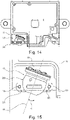
- Fig. 14 is top view of the housing base 9 wherein the oriented camera sub-assembly 10 is mounted to the housing base 9 with the retainer ring 31.
- Fig. 15 is an enlarged view of the area marked with the rectangle R in Fig. 14 .
- the retainer ring 31 with the camera sub-assembly 10 is attached to the housing base 9 with the guiding pins 18.
- the fixed orientation of the optical axis 11 of the camera sub-assembly 10 depends on the particular application of the driver monitoring system 1.
- the angle ⁇ of the optical axis 11 of camera sub-assembly 10 can be selected between -20° and +20° to the nominal position 15.
- Fig. 16 is an enlarged and partial side view of the housing base 9 with the mounted camera sub-assembly 10.
- the retainer ring 31 with the camera sub-assembly 10 is attached to the housing base 9 with the guiding pins 18.
- the fixed orientation of the optical axis 11 of the camera sub-assembly 10 depends on the particular application of the driver monitoring system 1.
- the angle ⁇ of the optical axis 11 of camera sub-assembly 10 can be selected between -20° and +20° to the nominal position 15. Here the optical axis 11 is pointing down.
- Fig 17 is a front view of the housing base 9 with the mounted camera sub-assembly showing an example of extreme adjustment of the camera sub assembly 10. As shown here, an aperture opening 13 of the camera sub assembly 10 is pointing to the upper left. This is only one of several adjustments of the camera sub-assembly 10 and should not be regarded as a limiting factor of the invention.
- Fig. 18 is a perspective view of the outer housing 7 of the driver monitoring system 1.
- the outer housing 7 is composed of the housing base 9 and a housing cover 8.
- the driver monitoring system 1 holds the camera sub-assembly 10 and an infrared module 12.
- the outer housing 7 partly encloses the camera sub-assembly 10 and with the housing cover 8 and the housing base 9 the camera sub-assembly 10 is held in position in the driver monitoring system 1.
- the housing base 9 has at least one mounting ear 6 for fixing the driver monitoring system 1 in the vehicle 2 (see Fig. 1 ).
- Figs. 19A and 19B show various views of a further embodiment of the retainer ring 31.
- the retainer ring 31 has the same general topology as the embodiment shown in Figs 9A to 9C .
- the retainer ring 31, shown here, has ability to retain camera sub-assembly 10 before glue 29 is applied.
- the spheroidal inner topology 32 of the retainer ring 31 is centred in the middle plane 36 of the retainer ring 31.
- the housing part 20 of the camera sub-assembly 10 has a spherical topology 21 to match the spheroidal inner topology 32 (counter-topology) on the retainer ring 31.
- Figs. 20A to 20B show the stages of mounting the camera sub-assembly 10 and the retainer ring 31 as shown in the embodiment of Figs. 19A and 19B .
- the housing part 20 of the camera sub-assembly 10 has the gripping base 22 which in contact with the gripping tool 26, which is used for gripping during the assembly of the camera sub-assembly 10 with the retainer ring 31.
- the jig 25 grasps the retainer ring 31 by the two lugs 33.
- the housing part 20 of the camera sub-assembly 10 is inserted into the retainer ring 31.
- an additional insertion force 19 is applied so that housing part 20 of the camera sub-assembly 10.
- the insertion force 19 is necessary that the housing part 20 of the camera sub-assembly 10 gets over the initial interference with retainer ring 31.
- the insertion force 19 is parallel to the optical axis 11.
- the gripping tool 26 is in contact with the gripping base 22 and applies the required adjustment torques to change the orientation of the optical axis 11.
- the gripping tool 26 is in contact with the gripping base 22 of the housing part 20 of the camera sub-assembly 10 until the glue (not shown here) is cured.
- Fig. 21 is an enlarged sectional view of the camera sub-assembly 10 in the nominal position 23, wherein the camera sub-assembly 10 is held by the retainer ring 31.
- the retainer ring 31 mounted according to the steps shown in Figure 20A to 20B .
- the spherical outer topology 21 of the housing part 20 of the camera sub-assembly is in contact with the spheroidal inner topology 32 of the retainer ring 31.
- the retainer ring 31 matches the spherical outer contour 21 of the housing part 20 of the camera sub-assembly 10 at a position 23 of a maximal diameter of the housing part 20 of the camera sub-assembly 10. The diameter is perpendicular to the optical axis 11.
- Fig. 22 is a side view of the camera sub-assembly 10, showing the possible orientations.
- the marking 27 in Fig. 22 shows the limitation of the rotational movement of the housing part 20 of the camera sub-assembly 10 in the retainer ring 31. The rotational movement is limited by the gripping base 22 of the housing part 20.
- Fig. 23A and 23B show a further embodiment of the camera sub-assembly 10.
- the housing part 20 of the camera sub-assembly 10 has a spherical outer topology 21.
- the housing part 20 with the spherical outer topology 21 hosts a pattern of indexing holes 40 (recesses), which are arranged along one generatrix 41.
- the number of indexing holes 40 shall be chosen according to the desired increment of the adjustment angle.
- Fig. 24 is a schematic view of embodiment of a mounting structure 30 for a camera sub-assembly 10 in an outer housing 7 of the driver monitoring system 1.
- the mounting structure 30 according to the embodiment shown here is defined by a spherical topology 8S of the housing cover 8 and an indexing pivot 50 sitting in the receptacle 16 of the housing base 9 of the outer housing 7.
- the housing cover 8 and the housing base 9 are made of aluminium.
- the spherical topology 8S of the housing cover 8 is in form fitting contact with the spherical outer topology 21 of the housing part 20 of the camera sub-assembly 10.
- the generatrix 41 of the housing part 20 with the indexing holes 40 is in contact with indexing teeth 52 of the indexing pivot 50.
- the indexing teeth 52 are arranged on a spherical sitting area 51.
- a bottom side 53 of the indexing pivot 50 has indexing fins 54.
- the indexing pivot 50 is fit to be manufactured out of a thermoplastic polymer (for example Polybutylenterephthalat (PBT), Acrylonitrile butadiene styrene (ABS), Polycarbonate (PC) etc.).
- a thermoplastic polymer for example Polybutylenterephthalat (PBT), Acrylonitrile butadiene styrene (ABS), Polycarbonate (PC) etc.
- Fig. 25 is an enlarged view of the area marked with A in Fig. 24 .
- the indexing pivot 50 has the spherical sitting area 51 with a groove 55 inside it.
- the groove 55 is as deep as needed in order to allow flexibility to indexing teeth 52.
- three indexing teeth 52 are located inside the groove 55 and are slightly projected outside.
- the indexing pivot 50 has a pivot shaft 58 which is sitting in the housing base 9.
- An air gap 59 is between the bottom side 53 and the housing base 9.
- Spring leaves 56 and stopper 57 are in the air gap 59 and ensure the stable positioning and movement of the indexing pivot 50.
- Fig. 26 is a schematic top view of the indexing pivot 50 of the mounting structure as shown in Fig. 24 .
- the indexing fins 54 (indicated with dashed lines), on the bottom side 53 (see Figs. 24 or 25 ) of the indexing pivot. In the embodiment shown here four indexing fins 54 are provided.
- the groove 55 of the spherical sitting area 51 has formed the indexing teeth 52. In the embodiment shown here three indexing teeth 52 are provided.
- the pivot shaft 58 of the indexing pivot 50 is arranged below the central indexing teeth 52.
- Fig. 27 is a schematic top view of a rotational area of the mounting structure of Fig. 24 .
- the housing base 9 has a special formed receptacle 16. Additionally, the receptacle 16 holds an indexing and sitting recess 60. As needed by application, the indexing and sitting recess 60 is positioned on the receptacle 16 of the housing base 9.
- the indexing and sitting recess 60 features a rotational area 62.
- the rotational area 62 has formed a rotational pattern of grooves 64.
- a central flat area 66 of the sitting recess 60 is used as a counter topology of for the indexing pivot 50 (see Fig. 25 ).
- the central flat area 66 has formed a hole 68 for fixation of the pivot shaft 58.
- the number of grooves 68 shall be chosen in accordance to the desired increment of adjustment angle.
- the sitting recess 60 is fit for manufacturing out of aluminium. It is obvious for any person skilled in the art that other material, like other metals or plastic materials, can be used instead of aluminium.
- Fig. 28 is a schematic representation of the angular adjustment of the camera sub-assembly 10 with the mounting structure 30 as shown in Fig. 24 .
- a preferred, cost effective solution is to clamp the housing part 20 of the camera sub-assembly 10 with its spherical outer topology 21 in cooperation with the spherical topology 8S of the housing cover 8.
- Existing screws can be used secure the housing cover 8 to the housing base 9.
- the indexing pivot 50 and the camera sub-assembly 10 are sandwiched between the housing cover 8 to the housing base 9.
- the spring leaves 56 are provided in the air gap 59 (see Fig. 25 ).
- the tolerance to be compensated is estimated to be less than 1 mm.
- the spring leaves 56 will be stiff enough so that the camera sub-assembly 10 will not rattle.
- the assembly of the camera sub-assembly 10 to the outer housing 7 comprises several steps. First, the camera sub-assembly 10 is gripped by the assembly jig 25. Next, the indexing pivot 50 is lowered toward the housing base9 and the pivot shaft 58 being pushed through the hole 68 of the central flat area 66 (see Fig. 27 ). Thereby the pivot shaft 58 is fixed the housing base 9. As pivot shaft 58 shaft is pushed in, the pivot shaft 58 becomes captive while the spring leaves 56 become tense (see Fig. 25 ).
- the camera sub-assembly 10 is lowered onto the indexing pivot 50, in a way so that the indexing teeth 52 of the indexing pivot 50 reach the respective indexing holes 40 inside the housing part 20 of the camera sub-assembly 10.
- the spherical sitting area 51 of indexing pivot 50 gets in contact with the spherical outer topology 21 housing part 20 of the camera sub-assembly 10 camera (except for the groove 55).
- the housing cover 8 is lowered onto the housing base 9 and becomes fully in contact with the housing base 9.
- the spring leaves 58 of the indexing pivot 50 accommodate the overlap and the spherical topology 8S of the housing cover 8 gets into contact with the spherical outer topology 21 of the housing part 20 of the camera sub-assembly 10.
- the two adjustment angles are adjusted to the functional position of the assembly, as required by the parameters of the vehicle 2.
- the adjustment is carried out with the help of the gripping tool 26.
- the solutions for gripping may vary and the solution shown in Fig. 28 should not be regarded as a limitation of the invention.
- the indexing teeth 52 on the indexing pivot 50 will get into contact with another set of indexing holes 40 in the spherical outer topology 21 of the housing part 20 of the camera sub-assembly 10. Due to the indexing, the angular adjustment shall be done in steps equal to the angular ratio of hole pattern. Only the housing part 20 of the camera sub-assembly 10 is rotated.
- the indexing fins 54 on the indexing pivot 50 will get into contact with the set of indexing grooves 64 of the indexing and sitting recess 60 (see Fig. 27 ).
- the housing part 20 of the camera sub-assembly 10 and the indexing pivot 50 rotate together. Due to the indexing, the angular adjustment shall be done in steps equal to the angular ratio of groove pattern of the indexing and sitting recess 60.
- the rotation moment is transferred from the griping tool 26 to the housing part 20 of the camera sub-assembly 10 to the indexing teeth 52 of the indexing pivot 50 and to the indexing fins 54 of the indexing pivot 50.
- the set of the angular adjustment of the housing part 20 of the camera sub-assembly 10 can be carried out optionally in the manufacturer's plant.
- the elasticity of the indexing teeth 52 and the indexing fins 54 ensure an easy position change.
Landscapes
- Engineering & Computer Science (AREA)
- Multimedia (AREA)
- Signal Processing (AREA)
- Fittings On The Vehicle Exterior For Carrying Loads, And Devices For Holding Or Mounting Articles (AREA)
- Studio Devices (AREA)
Abstract
Description
- The invention relates to a driver monitoring system. Especially, the driver monitoring system comprises at least a camera sub-assembly which is positioned in an outer housing. The optical axis of the camera sub-assembly is pointing to an outside of the outer housing. The outer housing is defined by a housing cover and a housing base.
- Furthermore invention relates to a method for manufacturing a driver monitoring system. The driver monitoring system comprises at least a camera sub-assembly positioned in an outer housing, so that its optical axis is pointing to an outside of the outer housing. The outer housing is defined by a housing cover and a housing base.
- International patent application
WO 2019/164724 A1 discloses a camera module assembly. An outer housing for the camera module comprises a front shell with a window and a rear shell. The camera core includes a lens assembly, a sensor assembly, and a sensor housing. The sensor assembly is disposed within the sensor housing, and the sensor housing is fixed to the lens assembly. - International patent application
WO 2018/219951 A1 relates to a camera module for a motor vehicle. The camera module is used for driver monitoring in the passenger compartment. The camera module has at least one printed circuit board and a shield for enclosing said printed circuit board. The shield comprises at least a first shielding part and a second shielding part. - U.S. patent application
US 2019/208091 A1 discloses a camera module for a vehicular vision system. The camera module includes a metal front housing, a lens holder and a metal rear housing. The front housing houses a printed circuit board having an imager disposed thereat. The lens holder is attached at a front portion of the housing so that a lens assembly is optically aligned with the imager. - U.S. patent application
US 2018/222402 A1 discloses a camera housing portion which has an imaging sensor at a base portion of the camera housing portion. A lens system is at a first portion of the camera housing portion. A first circuit board is provided that includes circuitry associated with the imaging sensor, which is disposed at a second circuit board that is in board-to-board electrical connection with the first circuit board. The camera housing portion and a connector portion are joined together to encase the first and second circuit boards. - In general, vision cameras are more and more present in vehicles. They are used for scanning the environment of the vehicle and also the driver and passengers, sending the data to an ECU (electronic control unit) that is processing the data and sending out warnings to the driver or acting on the vehicle brakes. The most advance vision cameras use two cameras working in stereo configuration to output also the distance. An algorithm is used and the ECU receives the distance to the object.
- In existing prior art systems, the vision camera is calibrated during installation with regards to relative positioning imager sensor on the. The vision camera is fixed by a fixing glue, which fixes camera housing to printed circuit board after curing. The vision camera and the printed circuit board are temporarily fixed together by an external fixture until glue is cured. The sub-assembly of the camera and the printed circuit board are afterwards fixed to the housing.
- With different car lines, the required position of an infrared module in the vehicle may differ from car line to car line, in order to keep focus on the driver. In order to function properly, the installation position of the infrared module, included in the driver monitoring system, is made at different angles as well as inside the electronic control unit (ECU) of the driver monitoring system. This is due to the necessity of mounting of the driver monitoring system's ECU in different positions in the vehicle, also if it is mounted on vehicles with steering on the left or right side, but not limited to it. This brings about a diversity of housing and cover parts, so that similar projects do not share the same housings and covers. It may be that ECUs with identical functions and printed circuit boards are different in construction due to that. Consequently, the development, validation and manufacturing cost is therefore high for such a driver monitoring system.
- It is an object of the present invention to provide a driver monitoring system which can be used for a wide variety of car lines. Additionally, the inventive driver monitoring system should save costs and reduce the variety of parts of the driver monitoring system.
- The above object is achieved by a driver monitoring system which comprises the features of
claim 1. - It is a further object of the present invention to provide a method for manufacturing driver monitoring system which allows a safe and secure orientation of an optical axis of a vision camera of the driver monitoring system and can be used for a wide variety of car lines. Additionally, the inventive method should save costs and reduce the variety of parts of the driver monitoring system.
- The above object is achieved by a method for manufacturing a driver monitoring system which comprises the features of
claim 11. - According to the invention a housing part for the camera sub-assembly has a spherical outer topology. A mounting structure is positioned at least in relation to a receptacle of the housing base. The mounting structure allows an angular adjustment of the optical axis of the camera sub-assembly.
- The advantage of the driver monitoring system is it can be used with different car lines. Furthermore, the driver monitoring system can reflect as well the various needs of the drivers. With the present invention the diversity of housing parts and cover parts is reduced and the development, validation and manufacturing cost are reduced as well, because the inventive embodiment of the driver monitoring system can serve multiple carlines.
- According to an embodiment of the present invention, the mounting structure is a retainer ring with a spheroidal inner topology. The spheroidal inner topology of the retainer ring matches the spherical outer contour of the housing part of the camera sub-assembly.
- The advantage is that the orientation of the optical axis of the camera sub-assembly can be set before the camera sub-assembly is mounted in the outer housing (the same outer housing for various car lies or needs). Additionally, the match of the spheroidal inner topology of the retainer ring and the spherical outer contour of the housing part of the camera sub-assembly allow a rotation of the housing part of camera sub-assembly. Consequently, multiple relative positions of the retainer ring and the camera sub-assembly are possible, which is due to the nature of the spherical joint.
- According to a further embodiment of the present invention the spherical inner topology of the retainer ring is centred in a middle plane of the retainer ring. Consequently, the spherical inner topology of the retainer ring matches the spherical outer contour of the housing part of the camera sub-assembly at a position of a maximal diameter of the housing part of the camera sub-assembly. The maximal diameter is perpendicular to the optical axis.
- The advantage of this embodiment is that as well multiple relative positions of the retainer ring and the camera sub-assembly are possible, which is due to the nature of the spherical joint. Furthermore, this embodiment achieves an additional robustness against a failure case that the camera sub-assembly could fall out of the lock with the retainer ring or lose the relative position to it.
- According to an embodiment of the invention the set spatial orientation of the optical axes is fixed by a glue. The glue is provided such that a relative movement of the retainer ring and the spherical outer contour of the housing part of the camera sub-assembly is blocked. The glue is applied as a seam at a boundary between the retainer ring and the housing part of the camera sub-assembly and/or in at least one window of the retainer ring.
- The advantage of the cured glue is that it locks the position of the housing part of the camera sub-assembly relative to the retainer ring and thereby fixes the orientation of the optical axis for further mounting.
- According to an embodiment of the invention, the retainer ring is centred with is spherical inner topology of in a middle plane of the retainer ring and the retainer ring matches the spherical outer contour of the housing part of the camera sub-assembly. After spatial orientation of the optical axis the retainer ring is in tight fit contact with the housing part of the camera sub-assembly.
- The advantage of the embodiment is that the spatial orientation of the optical axis can be maintained without a glue. In order to position the optical axis of the camera sub-assembly in the nominal position, the retainer ring warmed up so the interference is reduced. After the camera sub-assembly is positioned in the retainer ring, it can be as well oriented to achieve the final angular orientation of the optical axis. Immediately afterwards, the retainer ring is to be cooled down by itself or via a special operation (blowing of cold air over the retainer ring etc.) and the tight fit is achieved. Unintended rotation of the camera sub-assembly in the field is prevented, therefore. Ideally, the housing part of the camera sub-assembly and the retainer ring shall be manufactured out of metal. The same material is needed so that dilation and contraction of fit maintains clamping.
- According to an embodiment of the invention, the mounting structure is defined by an indexing pivot and a spherical topology of the housing cover. The indexing pivot is positioned in the receptacle of the housing base and a pivot shaft of the indexing pivot is sitting in the housing base.
- According to a further embodiment of the invention, the indexing pivot has a plurality of indexing teeth, which are in contact with set of indexing holes in the spherical outer topology of the housing part of the camera sub-assembly. The spherical topology of the housing cover is in form fitting contact with the spherical outer topology of the housing part of the camera sub-assembly. Additionally, the indexing pivot has indexing fins at a bottom side. The indexing fins interact with grooves of an indexing and sitting recess, which is positioned on the receptacle of the housing base.
- The advantage of the inventive embodiment is that with the indexing pivot an angular adjustment solution can be glue free for a spherical camera for a housing part of the camera sub-assembly. With the invention it is possible to accommodate multiple installation angles of the optical axis of the camera sub-assembly. There is no need of redesign and revalidate concepts when a new carline is imposing a different position of driver monitoring system inside the vehicle. The angular adjustment of field of view direction is possible at any moment, with a chosen Increment. There is no need of providing a glue or other fixation element in order to fix and maintain the orientation of the optical axis of the camera sub-assembly. The cost of development, validation and manufacturing new modules is reduced with the invention across a family of products serving multiple carlines. One single product type can be manufactured, which serves multiple carlines. A customer may simply adjust the field of view direction to the needed angle, without effort or intervention of manufacturer.
- A method for manufacturing a driver monitoring system is characterized in that a housing part of the camera sub-assembly is positioned in cooperation with at least part of a mounting structure in a receptacle of the housing base. The mounting of the housing cover to the housing base holds the housing part of the camera sub-assembly held by the outer housing cover. The camera sub-assembly is positioned in the outer housing so that its optical axis is pointing to an outside of the outer housing
- According to one embodiment, the mounting structure is a retainer ring which surrounds the spherical outer topology of the housing part of the camera sub-assembly. An orientation of the optical axis of the camera sub-assembly is adjusted by a gripping tool prior to positioning the retainer ring on the receptacle of the housing base. The adjusted orientation of the optical axis of the camera sub-assembly is maintained by a glue applied as a seam between the retainer ring and the spherical outer topology of the housing part and/or by a glue filled in at least one window of the retainer ring. According to a further embodiment the adjusted orientation of the optical axis of the camera sub-assembly is maintained by a tight fit contact of the retainer ring with the housing part of the camera sub-assembly after a spatial orientation of the optical axes.
- The advantage of the above described embodiment is an angular adjustment concept for an optical axis of the camera sub-assembly, so that one concept of a driver monitoring system can be used in different types of vehicles. The cost of development, validation and manufacturing new modules of a driver monitoring system is reduced with the invention.
- According to a further embodiment of the invention, the mounting structure is defined by a spherical topology of the housing cover and an indexing pivot, sitting in the receptacle of the housing base. An orientation of the optical axis of the camera sub-assembly is adjusted by a gripping tool after the spherical topology of the housing cover is in form fitting contact with the spherical outer topology of the housing part of the camera sub-assembly. An orientation of the optical axis of the camera sub-assembly is maintained in a first rotating direction by indexing teeth of the indexing pivot which get into contact with another set of indexing holes in the spherical outer topology of the housing part of the camera sub-assembly. An orientation of the optical axis of the camera sub-assembly is maintained in a second rotating direction by indexing fins of the indexing pivot, which get into contact with a set of indexing grooves of an indexing and sitting recess on the receptable of the housing base.
- The advantage of the above embodiment is that a re-adjustment of the orientation of the optical axis of the camera sub-assembly can be carried out in two directions at any moment. A scenario may be that an original equipment manufacturer has a stock of driver monitoring systems or electronic control units with camera, however different car lines are assembled. Same driver monitoring systems or electronic control units are taken from logistic and, during mounting on the vehicle assembly line, the angles are adjusted according to the particular angular position requirement of each car line. If desired, the adjustment moment (torque) may be tuned so that change of angle may be done by hand by an operator, or the opposite is possible if desired. If desired, the screws close to the sandwich of the housing part of the camera sub-assembly and the mounting structure can bring additional clamping to the package.
- The numerous advantages of the disclosure may be better understood by those skilled in the art by reference to the accompanying figures in which:
-
Figure 1 is a schematic representation of the placement of a driver monitoring system camera according to an embodiment of the prior art. -
Figure 2 is sliced view of an exemplary model of a state of the art vision camera. -
Figure 3 is a perspective view of a state of the art housing of the vision camera and the printed circuit board. -
Figure 4 is a sliced perspective view exemplary a state of the art module of the vision camera. -
Figure 5 is a detailed view of a state of the art mounting of a camera a driver monitoring system. -
Figure 6 is a perspective view driver monitoring system with a vision camera module and an infrared module according to the prior art. -
Figures 7A to 7C are various views of one embodiment of the camera sub-assembly. -
Figures 8A to 8C are various views of the camera sub-assembly with a mounting structure for adjusting various orientations of the camera sub-assembly. -
Figure 9A and 9 are various views of an embodiment of the mounting structure in the form of a retainer ring. -
Figure 10 is a partial sectional view of a portion of the housing base with the receptacle for the camera sub-assembly. -
Figure 11A to 11E show the stages of mounting and orienting the camera sub-assembly with respect to the retainer ring. -
Figure 12 is a perspective view of the housing base with the mounted camera sub-assembly. -
Figure 13 is a sectional and enlarged view of the camera sub-assembly mounted to the housing base. -
Figure 14 is top view of the housing base wherein the oriented camera sub-assembly is mounted to the housing base with the retainer ring. -
Figure 15 is an enlarged view of the area marked with the rectangle R inFig. 14 . -
Figure 16 is an enlarged and partial side view of the housing base with the mounted camera sub-assembly. -
Figure 17 is a front view of the housing base with the mounted camera sub-assembly showing an example of extreme adjustment of the camera sub-assembly about two axes. -
Figure 18 is a perspective view of the outer housing, which is composed of a housing base and a housing cover. -
Figure 19A-19B show various views of a further embodiment of the retainer ring. -
Figure 20A-20B show the stages of mounting the camera sub-assembly and the retainer ring as shown in the embodiment ofFigs. 19A and 19B . -
Figure 21 is an enlarged sectional view of the camera sub-assembly in the nominal position mounted according to the steps shown inFigure 20A-20B . -
Figure 22 is a side view of the camera sub-assembly, showing the possible orientations. -
Figure 23A-23B are various views of a further embodiment of the camera sub-assembly. -
Figure 24 is a schematic view of embodiment of a mounting structure for a camera sub-assembly in an outer housing of the driver monitoring system. -
Figure 25 is an enlarged view of the area marked with A ofFig. 24 . -
Figure 26 is a schematic top view of the indexing pivot of the mounting structure ofFig. 24 . -
Figure 27 is a schematic top view of a rotational area of the mounting structure ofFig. 24 . -
Figure 28 is a schematic representation of the angular adjustment camera sub-assembly with the mounting structure ofFig. 24 . - In the ensuing description, numerous specific details are provided to enable maximum understanding of the embodiments that are provided by way of example. The embodiments may be implemented with or without specific details, or else with other methods, components, materials, etc. In other circumstances, well-known structures, materials, or operations are not illustrated or described in detail so that various aspects of the embodiments will not be obscured. Reference in the course of the present description to "an embodiment" or "one embodiment" means that a particular structure, peculiarity, or characteristic described in connection with its implementation is comprised in at least one embodiment. Hence, phrases such as "in an embodiment" or "in one embodiment" that may recur in various points of the present description do not necessarily refer to one and the same embodiment. Furthermore, the particular structures, peculiarities, or characteristics may be combined in any convenient way in one or more embodiments
- Same reference numerals refer to same elements or elements of similar function throughout the various figures. Furthermore, only reference numerals necessary for the description of the respective figure are shown in the figures. The shown embodiments represent only examples of how the invention can be carried out. This should not be construed as a limitation of the invention.
-
Fig. 1 shows the arrangement of adriver monitoring system 1 inside amotor vehicle 2 according to an embodiment of the prior art. Thedriver monitoring system 1 is mounted at or close to awindshield 3 of themotor vehicle 2, so that at least one vision device 10 (seeFig. 2 ) of thedriver monitoring system 1 is looking at adriver 5 of themotor vehicle 2. Especially, alens 4 of thevision device 10, which is, for example, avision camera 11, is pointing at thedriver 5. -
Fig. 2 is sliced view of an exemplary model of a state of theart vision camera 100. Thevision camera 100 is calibrated during installation with regards to relative positioning animager sensor 102 on a printedcircuit board 103. Thevision camera 100 is fixed by a fixingglue 105, which fixescamera housing 101 to the printedcircuit board 103 after curing. Thevision camera 100 and the printedcircuit board 103 are temporarily fixed together by external fixture (not shown) until the fixingglue 105 is cured. The assembly of thevision camera 100 and the printedcircuit board 103 is afterwards fixed to thecamera housing 101. Thecamera barrel 106 and the printedcircuit board 103 are seated by 3 spheres on the camera on prismatic grooves (not shown) on thecamera housing 101. Aretainer ring 107 is slipped over thelens barrel 106 with rubber sector being compressed between thecamera housing 101 andvision camera 10, from the other side. Theretainer ring 107 is made from flexible plastic and rubber. -
Fig. 3 is a perspective view of a state of theart housing part 110 of thevision camera 100 and the printed circuit board (not shown here). -
Fig. 4 is an exemplary sliced perspective view of a state of the art module of thevision camera 100. The printedcircuit board 103 is attached with a fixingglue 105 to thecamera housing 101. -
Fig. 5 is a detailed view of a state of the art mounting of avison camera 100 to anouter housing 7 of adriver monitoring system 1. The printedcircuit board 103 is attached to thecamera housing 101. Thevision camera 100 is mounted in theouter housing 101, so that theoptical axis 11 of thevision camera 100 is arranged at an angle in relation with the driver of thevehicle 2. -
Fig. 6 is a perspective view of adriver monitoring system 1 according to an embodiment of the prior art. Thedriver monitoring system 1 has avision camera 100 and aninfrared module 12. Thevision camera 100 defines a camera window (not shown). Theinfrared module 12 defines an IR window (not shown). Theinfrared module 12 of the prior artdriver monitoring system 1 has twoinfrared diodes 17. The number ofdiodes 17 should not be regarded as a limitation. Thedriver monitoring system 1 has anouter housing 7 which is composed of ahousing cover 8 and ahousing base 9. Thehousing base 9 has at least one mountingear 6 for fixing thedriver monitoring system 1 in thevehicle 2. - The
driver monitoring system 1 is positioned inside thevehicle 2 in such a manner that the driver's 5 face is predictably in the middle of the vision camera's 100 field of view. Theinfrared module 12 is positioned in the vicinity of thevision camera 100 so that if natural light is insufficient, the driver is lit in a non-distracting manner by infrared light. Theinfrared diodes 17 are populated on a printed circuit board which is further attached, for example with thermal paste, to the coolingdome 14. According to the prior art, the cooling dome14 is made of metal. -
Figs. 7A to 7C are various views of one embodiment of thecamera sub-assembly 10. Thecamera sub-assembly 10 comprises alens barrel 106 which is surrounded by ahousing part 20 that has a spherical outer topology 21 (or spheroidal topology). Thehousing part 20 of thecamera sub-assembly 10 has formed a grippingbase 22, which is utilized for grippingcamera sub-assembly 10 to achieve a desired orientation of anoptical axis 11. A printedcircuit board 103 with animage sensor 102 is attached to the grippingbase 22. Thelens barrel 106 defines theoptical axis 11 which is perpendicular on theimage sensor 102. -
Figs. 8A to 8C show various views of thecamera sub-assembly 10 with a mountingstructure 30 for adjusting and fixing various orientations of theoptical axis 11 of thecamera sub-assembly 10. In the embodiment shown here the mountingstructure 30 is aretainer ring 31.Fig. 8A shows the situation that the sphericalouter topology 21 of thehousing part 20 is surrounded by theretainer ring 31. Theoptical axis 11 of thecamera sub-assembly 10 is parallel to an axis of the cartesian coordinate system (exemplary theoptical axis 11 is parallel to the Z-axis of the coordinate system).Fig. 8B shows the situation that theoptical axis 11 of thecamera sub-assembly 10 is tilted by an angle α in a plane of the cartesian coordinate system (exemplary theoptical axis 11 is tilted in the X/Z-plane of the coordinate system).Fig. 8C shows the situation that theoptical axis 11 of thecamera sub-assembly 10 is tilted by an angle β in a plane of the cartesian coordinate system (exemplary theoptical axis 11 is tilted in the Y/Z-plane of the coordinate system). The maximum tilt can be in a range of - α to + α or -β to +β, wherein the maximum value of α and β is 20°. -
Figs. 9A to 9C show various views of theretainer ring 31 which is used as the mountingstructure 30 for thecamera sub-assembly 10. Theretainer ring 31 has formed a spheroidalinner topology 32. The spheroidalinner topology 32 of theretainer ring 31 matches the sphericalouter contour 21 of thehousing part 20 of thecamera sub-assembly 10. Thecamera sub-assembly 10, when surrounded by the retainer ring 31 (seeFigs. 8A-8C ) can be set at a desired angle. Theretainer ring 31 has twolugs 33 with centring holes 35. The centring holes 35 of theretainer ring 31 provide an exact seating of thecamera sub-assembly 10 on the housing base 9 (seeFig. 10 ).Another, optional function of theretainer ring 31 is to facilitate access of glue 39 (seeFig. 11E ) to the interface between theretainer ring 31 and the sphericalouter contour 21 of thehousing part 20 of thecamera sub-assembly 10. Therefore, the embodiment of theretainer ring 31 shown here has twowindows 34, which are used to apply theglue 39. -
Fig. 10 is a partial sectional view of a portion of thehousing base 9 with thereceptacle 16 for theretainer ring 31 of thecamera sub-assembly 10. Awall 9W ofhousing base 9 separated the receptacle form the inner portion 9I ofhousing base 9. In addition, thereceptacle 16 for theretainer ring 31 has two guidingpins 18 help to locate theretainer ring 31 at thehousing base 9. The guiding pins 18 reach into the centring holes 35 of thelugs 33 of the retainer ring 31 (seeFig. 9A-9C ). As needed by application, the guiding pins 18 can be located on thehousing cover 8, instead. -
Figs. 11A to 11E provide an insight of the stages of mounting and orienting thecamera sub-assembly 10 with respect to theretainer ring 31. InFig. 11A the step of the mounting process is shown that theretainer ring 31 is fixed inside ajig 25. Thejig 25 grasps theretainer ring 31 by the two lugs 33. In the next step as shown inFig. 11B thehousing part 20 of thecamera sub-assembly 10 is gripped by a grippingtool 26 at the grippingbase 22 of thehousing part 20 of thecamera sub-assembly 10. Thehousing part 20 is positioned in a nominal position wherein theoptical axis 11 is perpendicular to theretainer ring 31. In the step as shown inFig. 11C thehousing part 20 of thecamera sub-assembly 10 is rotated to the angle or angles imposed by the application. The grippingtool 26 is still in contact with the at the grippingbase 22 and thejig 25 still holds theretainer ring 31. As a result of therotation 29 thehousing part 20 is positioned such that theoptical axis 11 is angled with respect to theretainer ring 31. The cooperation of the sphericalouter topology 21 of thehousing part 20 of thecamera sub-assembly 10 and the spheroidal inner topology 32 (seeFig. 9A ) of theretainer ring 31 allow thefree rotation 29.Fig. 11D shows the process step wherein aglue 39 is applied at the boundary between thehousing part 20 of thecamera sub-assembly 10 and theretainer ring 31. The grippingtool 26 and thejig 25 are still active. Preferably, theglue 39 is applied as aseam 38 at the boundary between theretainer ring 31 and thehousing part 20 of thecamera sub-assembly 10.Fig. 11E shows an alternate or additional step. Here, theglue 39 is filled in at least onewindow 34 of theretainer ring 31. The grippingtool 26 and thejig 25 are still active. Afterglue 39 is cured, the grippingtool 26 and thejig 25 grippers are removed and thecamera sub-assembly 10 is ready for mounting. - A perspective view of the
housing base 9 with thecamera sub-assembly 10 mounted in thereceptacle 16 of thehousing base 9, is shown inFig. 12 . Here the mountingstructure 30 is theretainer ring 31 which holds the oriented and fixedcamera sub-assembly 10. A preferred, cost effective solution, is to clamp thecamera sub-assembly 10 with dedicated guiding pins 18 at thehousing base 9. The guiding pins 18 reach into the centring holes 35 seeFig. 9C ) of theretainer ring 31 lugs 33. -
Fig. 13 is a sectional and enlarged view of thecamera sub-assembly 10 mounted to thehousing base 9. The dedicated guiding pins 18 of thereceptacle 16 of thehousing base 9 reach into the centring holes 35 of thelugs 33 when theretainer ring 31 is pressed with aforce 19, acting on thelugs 33, towards thereceptacle 16. Theretainer ring 31 and consequently thecamera sub-assembly 10 is firmly mounted to thehousing base 9. - This is an economically fixation method, wherein the retainer ring is fixed to the housing base, with no additional fixation part or operation. A guaranteed interference is needed between pins and holes, however one which does not lead to cracks in either part or need of high assembly forces. As interference would be variable with common part manufacturing precision, so will be the required assembly force, which may further mean a manufacturing challenge in making sure the final retainer ring position was reached.
- It may as well be desirable to have no residual mechanical stress in the resulting assembly.
- An alternate mounting method is "hot staking". Here the centring pins 18, likely together with
entire housing base 9, are made of plastic. Then a centring, intermediate fit of pins (sometimes called stakes) on the centring holes 35 is possible. After theretainer ring 31 together withcamera sub-assembly 10 has reached its final position on thehousing base 9, a specific "hot staking head" is lowered on the tips of guiding pins 18 (centring pins) and warms them up over to the point of slight melting. The flowing material is pushed down so that a "rivet head" is created on top oflugs 33, thus locking thecamera sub-assembly 10 and thehousing base 9 together. - An alternate mounting method is "riveting". This mounting method is used once the centring pins 18, likely together with
entire housing base 9. are made of metal, for example aluminium, low-carbon steel or copper, or other ductile materials. In the beginning a centring and intermediate fit ofpins 18 on centring holes is carried out. After theretainer ring 31 together the withcamera sub-assembly 10 have reached its final position onhousing base 9, a specific press head (not shown) is lowered on the tips of centring pins 18 A specific stress with respect to the flow characteristic of a respective material is induced inside the tips of centring pins 18. The flowing material is pushed down so that a "rivet head" is created on top oflugs 33, thus locking thecamera sub-assembly 10 and thehousing base 9 together. The press may use a special die geometry to form the rivet head. - A further, alternate mounting method is a fixation by nuts, provided the tip of centring pins 18 are threaded. In the beginning a centring and intermediate fit of
pins 18 on centring holes is carried out. After theretainer ring 31 together withcamera sub-assembly 10 has reached its final position onhousing base 9, a specific screwing machine (not shown) brings a nut to each threadedcentring pin 18 and tightens it. -
Fig. 14 is top view of thehousing base 9 wherein the orientedcamera sub-assembly 10 is mounted to thehousing base 9 with theretainer ring 31.Fig. 15 is an enlarged view of the area marked with the rectangle R inFig. 14 . Theretainer ring 31 with thecamera sub-assembly 10 is attached to thehousing base 9 with the guiding pins 18. The fixed orientation of theoptical axis 11 of thecamera sub-assembly 10 depends on the particular application of thedriver monitoring system 1. The angle α of theoptical axis 11 ofcamera sub-assembly 10 can be selected between -20° and +20° to thenominal position 15. -
Fig. 16 is an enlarged and partial side view of thehousing base 9 with the mountedcamera sub-assembly 10. Theretainer ring 31 with thecamera sub-assembly 10 is attached to thehousing base 9 with the guiding pins 18. The fixed orientation of theoptical axis 11 of thecamera sub-assembly 10 depends on the particular application of thedriver monitoring system 1. The angle β of theoptical axis 11 ofcamera sub-assembly 10 can be selected between -20° and +20° to thenominal position 15. Here theoptical axis 11 is pointing down. - It is noted, that the
glue 39 required for fixing the set orientation of theoptical axis 11 is not shown inFigs. 14, 15 and16 . -
Fig 17 is a front view of thehousing base 9 with the mounted camera sub-assembly showing an example of extreme adjustment of thecamera sub assembly 10. As shown here, anaperture opening 13 of thecamera sub assembly 10 is pointing to the upper left. This is only one of several adjustments of thecamera sub-assembly 10 and should not be regarded as a limiting factor of the invention. -
Fig. 18 is a perspective view of theouter housing 7 of thedriver monitoring system 1. Theouter housing 7 is composed of thehousing base 9 and ahousing cover 8. Thedriver monitoring system 1 holds thecamera sub-assembly 10 and aninfrared module 12. Theouter housing 7 partly encloses thecamera sub-assembly 10 and with thehousing cover 8 and thehousing base 9 thecamera sub-assembly 10 is held in position in thedriver monitoring system 1. Thehousing base 9 has at least one mountingear 6 for fixing thedriver monitoring system 1 in the vehicle 2 (seeFig. 1 ). -
Figs. 19A and 19B show various views of a further embodiment of theretainer ring 31. Theretainer ring 31 has the same general topology as the embodiment shown inFigs 9A to 9C . Theretainer ring 31, shown here, has ability to retaincamera sub-assembly 10 beforeglue 29 is applied. The spheroidalinner topology 32 of theretainer ring 31 is centred in themiddle plane 36 of theretainer ring 31. As mentioned in the description with regard toFig. 7A to 7C thehousing part 20 of thecamera sub-assembly 10 has aspherical topology 21 to match the spheroidal inner topology 32 (counter-topology) on theretainer ring 31. -
Figs. 20A to 20B show the stages of mounting thecamera sub-assembly 10 and theretainer ring 31 as shown in the embodiment ofFigs. 19A and 19B . Thehousing part 20 of thecamera sub-assembly 10 has the grippingbase 22 which in contact with the grippingtool 26, which is used for gripping during the assembly of thecamera sub-assembly 10 with theretainer ring 31. Thejig 25 grasps theretainer ring 31 by the two lugs 33. Thehousing part 20 of thecamera sub-assembly 10 is inserted into theretainer ring 31. - Additionally, as shown in
Fig. 20B anadditional insertion force 19 is applied so thathousing part 20 of thecamera sub-assembly 10. Theinsertion force 19 is necessary that thehousing part 20 of thecamera sub-assembly 10 gets over the initial interference withretainer ring 31. Theinsertion force 19 is parallel to theoptical axis 11. After theretainer ring 31 has reached the final position the angular adjustment can be carried out. The grippingtool 26 is in contact with the grippingbase 22 and applies the required adjustment torques to change the orientation of theoptical axis 11. The grippingtool 26 is in contact with the grippingbase 22 of thehousing part 20 of thecamera sub-assembly 10 until the glue (not shown here) is cured. -
Fig. 21 is an enlarged sectional view of thecamera sub-assembly 10 in thenominal position 23, wherein thecamera sub-assembly 10 is held by theretainer ring 31. Theretainer ring 31 mounted according to the steps shown inFigure 20A to 20B . The sphericalouter topology 21 of thehousing part 20 of the camera sub-assembly is in contact with the spheroidalinner topology 32 of theretainer ring 31. Theretainer ring 31 matches the sphericalouter contour 21 of thehousing part 20 of thecamera sub-assembly 10 at aposition 23 of a maximal diameter of thehousing part 20 of thecamera sub-assembly 10. The diameter is perpendicular to theoptical axis 11. -
Fig. 22 is a side view of thecamera sub-assembly 10, showing the possible orientations. Theretainer ring 31, as positioned in the embodiment shown inFig. 21 , limits the variety of the angle α around the nominal position of 15°. The marking 27 inFig. 22 shows the limitation of the rotational movement of thehousing part 20 of thecamera sub-assembly 10 in theretainer ring 31. The rotational movement is limited by the grippingbase 22 of thehousing part 20. -
Fig. 23A and23B show a further embodiment of thecamera sub-assembly 10. Thehousing part 20 of thecamera sub-assembly 10 has a sphericalouter topology 21. Thehousing part 20 with the sphericalouter topology 21 hosts a pattern of indexing holes 40 (recesses), which are arranged along onegeneratrix 41. The number of indexing holes 40 shall be chosen according to the desired increment of the adjustment angle. -
Fig. 24 is a schematic view of embodiment of a mountingstructure 30 for acamera sub-assembly 10 in anouter housing 7 of thedriver monitoring system 1. The mountingstructure 30 according to the embodiment shown here is defined by aspherical topology 8S of thehousing cover 8 and anindexing pivot 50 sitting in thereceptacle 16 of thehousing base 9 of theouter housing 7. Thehousing cover 8 and thehousing base 9 are made of aluminium. Thespherical topology 8S of thehousing cover 8 is in form fitting contact with the sphericalouter topology 21 of thehousing part 20 of thecamera sub-assembly 10. Thegeneratrix 41 of thehousing part 20 with the indexing holes 40 is in contact withindexing teeth 52 of theindexing pivot 50. Theindexing teeth 52 are arranged on a spherical sittingarea 51. Abottom side 53 of theindexing pivot 50 hasindexing fins 54. Theindexing pivot 50 is fit to be manufactured out of a thermoplastic polymer (for example Polybutylenterephthalat (PBT), Acrylonitrile butadiene styrene (ABS), Polycarbonate (PC) etc.). -
Fig. 25 is an enlarged view of the area marked with A inFig. 24 . Theindexing pivot 50 has the spherical sittingarea 51 with agroove 55 inside it. Thegroove 55 is as deep as needed in order to allow flexibility to indexingteeth 52. According to the embodiment as shown inFig. 24 threeindexing teeth 52 are located inside thegroove 55 and are slightly projected outside. Theindexing pivot 50 has apivot shaft 58 which is sitting in thehousing base 9. Anair gap 59 is between thebottom side 53 and thehousing base 9. Spring leaves 56 andstopper 57 are in theair gap 59 and ensure the stable positioning and movement of theindexing pivot 50. -
Fig. 26 is a schematic top view of theindexing pivot 50 of the mounting structure as shown inFig. 24 . The indexing fins 54 (indicated with dashed lines), on the bottom side 53 (seeFigs. 24 or25 ) of the indexing pivot. In the embodiment shown here fourindexing fins 54 are provided. Thegroove 55 of the spherical sittingarea 51 has formed theindexing teeth 52. In the embodiment shown here three indexingteeth 52 are provided. Thepivot shaft 58 of theindexing pivot 50 is arranged below thecentral indexing teeth 52. -
Fig. 27 is a schematic top view of a rotational area of the mounting structure ofFig. 24 . Thehousing base 9 has a special formedreceptacle 16. Additionally, thereceptacle 16 holds an indexing and sittingrecess 60. As needed by application, the indexing and sittingrecess 60 is positioned on thereceptacle 16 of thehousing base 9. The indexing and sittingrecess 60 features arotational area 62. Therotational area 62 has formed a rotational pattern ofgrooves 64. A centralflat area 66 of the sittingrecess 60 is used as a counter topology of for the indexing pivot 50 (seeFig. 25 ). The centralflat area 66 has formed ahole 68 for fixation of thepivot shaft 58. The number ofgrooves 68 shall be chosen in accordance to the desired increment of adjustment angle. The sittingrecess 60 is fit for manufacturing out of aluminium. It is obvious for any person skilled in the art that other material, like other metals or plastic materials, can be used instead of aluminium. -
Fig. 28 is a schematic representation of the angular adjustment of thecamera sub-assembly 10 with the mountingstructure 30 as shown inFig. 24 . A preferred, cost effective solution, is to clamp thehousing part 20 of thecamera sub-assembly 10 with its sphericalouter topology 21 in cooperation with thespherical topology 8S of thehousing cover 8. Existing screws (not shown) can be used secure thehousing cover 8 to thehousing base 9. Theindexing pivot 50 and thecamera sub-assembly 10 are sandwiched between thehousing cover 8 to thehousing base 9. For tolerance compensation on assembly direction the spring leaves 56 are provided in the air gap 59 (seeFig. 25 ). The tolerance to be compensated is estimated to be less than 1 mm. The spring leaves 56 will be stiff enough so that thecamera sub-assembly 10 will not rattle. - The assembly of the
camera sub-assembly 10 to the outer housing 7 (housing cover 8 and housing base 9) comprises several steps. First, thecamera sub-assembly 10 is gripped by theassembly jig 25. Next, theindexing pivot 50 is lowered toward the housing base9 and thepivot shaft 58 being pushed through thehole 68 of the central flat area 66 (seeFig. 27 ). Thereby thepivot shaft 58 is fixed thehousing base 9. Aspivot shaft 58 shaft is pushed in, thepivot shaft 58 becomes captive while the spring leaves 56 become tense (seeFig. 25 ). Then thecamera sub-assembly 10 is lowered onto theindexing pivot 50, in a way so that theindexing teeth 52 of theindexing pivot 50 reach the respective indexing holes 40 inside thehousing part 20 of thecamera sub-assembly 10. As this is accomplished, the spherical sittingarea 51 ofindexing pivot 50 gets in contact with the sphericalouter topology 21housing part 20 of thecamera sub-assembly 10 camera (except for the groove 55). Next thehousing cover 8 is lowered onto thehousing base 9 and becomes fully in contact with thehousing base 9. The spring leaves 58 of theindexing pivot 50 accommodate the overlap and thespherical topology 8S of thehousing cover 8 gets into contact with the sphericalouter topology 21 of thehousing part 20 of thecamera sub-assembly 10. The two adjustment angles are adjusted to the functional position of the assembly, as required by the parameters of thevehicle 2. The adjustment is carried out with the help of the grippingtool 26. The solutions for gripping may vary and the solution shown inFig. 28 should not be regarded as a limitation of the invention. - When the
housing part 20 of thecamera sub-assembly 10 is rotated in afirst direction 70, the indexingteeth 52 on theindexing pivot 50 will get into contact with another set of indexing holes 40 in the sphericalouter topology 21 of thehousing part 20 of thecamera sub-assembly 10. Due to the indexing, the angular adjustment shall be done in steps equal to the angular ratio of hole pattern. Only thehousing part 20 of thecamera sub-assembly 10 is rotated. - When the
housing part 20 of thecamera sub-assembly 10 is in asecond direction 80, theindexing fins 54 on theindexing pivot 50 will get into contact with the set ofindexing grooves 64 of the indexing and sitting recess 60 (seeFig. 27 ). Thehousing part 20 of thecamera sub-assembly 10 and theindexing pivot 50 rotate together. Due to the indexing, the angular adjustment shall be done in steps equal to the angular ratio of groove pattern of the indexing and sittingrecess 60. The rotation moment is transferred from the gripingtool 26 to thehousing part 20 of thecamera sub-assembly 10 to theindexing teeth 52 of theindexing pivot 50 and to theindexing fins 54 of theindexing pivot 50. - The set of the angular adjustment of the
housing part 20 of thecamera sub-assembly 10 can be carried out optionally in the manufacturer's plant. The elasticity of theindexing teeth 52 and theindexing fins 54 ensure an easy position change. - It is believed that the present disclosure and many of its attendant advantages will be understood by the foregoing description, and it will be apparent that various changes may be made in the form, construction and arrangement of the components without departing from the disclosed subject matter or without sacrificing all of its material advantages. The form described is merely explanatory, and it is the intention of the following claims to encompass and include such changes. Accordingly, the scope of the invention should be limited only by the claims appended hereto.
-
- 1
- Driver monitoring system
- 2
- Vehicle
- 3
- Windshield
- 4
- Lens
- 5
- Driver
- 6
- Mounting ear
- 7
- Outer housing
- 8
- Housing cover
- 8S
- Spherical topology
- 9
- Housing base
- 9I
- Inner portion
- 9W
- Wall
- 10
- Camera sub-assembly
- 11
- Optical axis
- 12
- Infrared module
- 13
- Aperture opening
- 14
- Cooling dome
- 15
- Nominal position
- 16
- Receptacle
- 17
- Infrared diode
- 18
- Guiding pin
- 19
- Force
- 20
- Housing part of the camera sub-assembly
- 21
- Spherical outer topology
- 22
- Gripping base
- 23
- Position
- 25
- Jig
- 26
- Gripping tool
- 27
- Marking
- 29
- Rotation
- 30
- Mounting structure
- 31
- Retainer ring
- 32
- Spheroidal inner topology
- 33
- Lug
- 34
- Window
- 35
- Centring holes
- 36
- Middle plane
- 38
- Seam
- 39
- Glue
- 40
- Indexing hole
- 41
- Generatrix
- 50
- Indexing pivot
- 51
- Spherical sitting area
- 52
- Indexing tooth
- 53
- Bottom side
- 54
- Indexing fin
- 55
- Groove
- 56
- Spring leave
- 57
- Stopper
- 58
- Pivot shaft
- 59
- Air gap
- 60
- Indexing and sitting recess
- 62
- Rotational area
- 64
- Groove
- 66
- Central flat area
- 68
- Hole
- 70
- First direction
- 80
- Second direction
- 100
- Vision camera
- 101
- Camera housing
- 102
- Imager sensor
- 103
- Printed circuit board
- 105
- Fixing glue
- 106
- Lens barrel
- 107
- Electronic device
- 110
- Housing part
Claims (15)
- A driver monitoring system (1), comprising
at least a camera sub-assembly (10) positioned in an outer housing (7) so that its optical axis (11) is pointing to an outside of the outer housing (7), wherein the outer housing (7) is defined by a housing cover (8) and a housing base (9),
characterized by
a housing part (20) for the camera sub-assembly (10) has a spherical outer topology (21); and
a mounting structure (30) is positioned at least in relation to a receptacle (16) of the housing base (9), wherein the mounting structure (30) allows an angular adjustment of the optical axis (11) of the camera sub-assembly (10). - The driver monitoring system (1) as claimed in claim 1, wherein the mounting structure (30) is a retainer ring (31) with a spheroidal inner topology (32), which matches the spherical outer contour (21) of the housing part (20) of the camera sub-assembly (10).
- The driver monitoring system (1) as claimed in claim 2, wherein the spherical inner topology (32) of the retainer ring (31) is centred in a middle plane (36) of the retainer ring (31) and the spherical inner topology (32) of the retainer ring (31) matches the spherical outer contour (21) of the housing part (20) of the camera sub-assembly (10) at a position (23) of a maximal diameter of the housing part (20) of the camera sub-assembly (10) which is perpendicular to the optical axis (11).
- The driver monitoring system (1) as claimed in the preceding claims 2-3, wherein a spatial orientation of the optical axes (11) is fixed by a glue (39) provided such that a relative movement of the retainer ring (31) and the spherical outer contour (21) of the housing part (20) of the camera sub-assembly (10) is blocked.
- The driver monitoring system (1) as claimed in claim 4, wherein the glue (39) is applied as a seam (38) at a boundary between the retainer ring (31) and the housing part (20) of the camera sub-assembly (10) and/or in at least one window (34) of the retainer ring (31).
- The driver monitoring system (1) as claimed in claim 2, wherein the retainer ring (31) is centred with is spherical inner topology (32) of in a middle plane (36) of the retainer ring (31) and the retainer ring (31) matches the spherical outer contour (21) of the housing part (20) of the camera sub-assembly (10) and after spatial orientation of the optical axis (11) the retainer ring (31) is in tight fit contact with the housing part (20) of the camera sub-assembly (10).
- The driver monitoring system (1) as claimed in claim 6, wherein the housing part (20) of the camera sub-assembly (10) and the retainer ring (31) are manufactured from the same material.
- The driver monitoring system (1) as claimed in claim 1, wherein the mounting structure (30) is defined by an indexing pivot (50), positioned in the receptacle (16) of the housing base (9) and a spherical topology (8S) of the housing cover (8), wherein a pivot shaft (58) of the indexing pivot (50) is sitting in the housing base (9).
- The driver monitoring system (1) as claimed in claim 8, wherein the indexing pivot (50) has a plurality of indexing teeth (52) which are in contact with set of indexing holes (40) in the spherical outer topology (21) of the housing part (20) of the camera sub-assembly (10) and wherein the spherical topology (8S) of the housing cover (8) is in form fitting contact with the spherical outer topology (21) of the housing part (20) of the camera sub-assembly (10).
- The driver monitoring system (1) as claimed in any of the claims 8 to 9, wherein the indexing pivot (50) has indexing fins (54) at a bottom side (53), wherein the indexing fins (54) interact with grooves (68) of an indexing and sitting recess (60) which is positioned on the receptacle (16) of the housing base (9).
- A method for manufacturing a driver monitoring system (1) wherein the driver monitoring system (1) comprises at least a camera sub-assembly (10) positioned in an outer housing (7) so that its optical axis (11) is pointing to an outside of the outer housing (7), and the outer housing (7) is defined by a housing cover (8) and a housing base (9),
comprising the steps of:• positioning a housing part (20) of the camera sub-assembly (10) in cooperation with at least part of a mounting structure (30) in a receptacle (16) of the housing base (9); and• mounting the housing cover (8) to the housing base (9) so that the housing part (20) of the camera sub-assembly (10) held by the outer housing cover (7). - The method as claimed in claim 11, wherein the mounting structure (30) is a retainer ring (31) which surrounds the a spherical outer topology (21) of the housing part (20) of the camera sub-assembly (10) and an orientation of the optical axis (11) of the camera sub-assembly (10) is adjusted by a gripping tool (26) prior to positioning the retainer ring (31) on the receptacle (16) of the housing base (9).
- The method as claimed in claim 12, wherein the adjusted orientation of the optical axis (11) of the camera sub-assembly (10) is maintained by a glue (39) applied as a seam (38) between the retainer ring (31) and the spherical outer topology (21) of the housing part (20) and/or by a glue (39) filled in at least one window (34) of the retainer ring (31) or by a tight fit contact the retainer ring (31) with the housing part (20) of the camera sub-assembly (10) after a spatial orientation of the optical axes (11).
- The method as claimed in claim 11, wherein the mounting structure (30) is defined by a spherical topology (8S) of the housing cover (8) and an indexing pivot (50) sitting in the receptacle (16) of the housing base (9) and an orientation of the optical axis (11) of the camera sub-assembly (10) is adjusted by a gripping tool (26) after the spherical topology (8S) of the housing cover (8) is in form fitting contact with the spherical outer topology (21) of the housing part (20) of the camera sub-assembly (10).
- The method as claimed in claim 14, wherein an orientation of the optical axis (11) of the camera sub-assembly (10) in a first rotating direction (70) is maintained by indexing teeth (52) of the indexing pivot (50) which get into contact with another set of indexing holes (40) in the spherical outer topology (21) of the housing part (20) of the camera sub-assembly (10) and an orientation of the optical axis (11) of the camera sub-assembly (10) in a second rotating direction (80) is maintained by indexing fins (54) of the indexing pivot (50) which get into contact with a set of indexing grooves (64) of an indexing and sitting recess (60) on the receptable (16).
Priority Applications (4)
| Application Number | Priority Date | Filing Date | Title |
|---|---|---|---|
| EP20202497.2A EP3984826A1 (en) | 2020-10-19 | 2020-10-19 | Driver monitoring system and method for manufacturing a driver monitoring system |
| PCT/EP2021/078141 WO2022084101A1 (en) | 2020-10-19 | 2021-10-12 | Vision module for monitoring a driver of a vehicle and method for manufacturing a vision module for monitoring a driver of a vehicle |
| CN202180065522.8A CN116194337A (en) | 2020-10-19 | 2021-10-12 | Visual module for monitoring a driver of a vehicle and method for manufacturing a visual module for monitoring a driver of a vehicle |
| US18/248,969 US20230396862A1 (en) | 2020-10-19 | 2021-10-12 | Vision module for monitoring a driver of a vehicle and method for manufacturing a vision module for monitoring a driver of a vehicle |
Applications Claiming Priority (1)
| Application Number | Priority Date | Filing Date | Title |
|---|---|---|---|
| EP20202497.2A EP3984826A1 (en) | 2020-10-19 | 2020-10-19 | Driver monitoring system and method for manufacturing a driver monitoring system |
Publications (1)
| Publication Number | Publication Date |
|---|---|
| EP3984826A1 true EP3984826A1 (en) | 2022-04-20 |
Family
ID=72943934
Family Applications (1)
| Application Number | Title | Priority Date | Filing Date |
|---|---|---|---|
| EP20202497.2A Pending EP3984826A1 (en) | 2020-10-19 | 2020-10-19 | Driver monitoring system and method for manufacturing a driver monitoring system |
Country Status (4)
| Country | Link |
|---|---|
| US (1) | US20230396862A1 (en) |
| EP (1) | EP3984826A1 (en) |
| CN (1) | CN116194337A (en) |
| WO (1) | WO2022084101A1 (en) |
Citations (8)
| Publication number | Priority date | Publication date | Assignee | Title |
|---|---|---|---|---|
| EP1469656A2 (en) * | 2003-04-14 | 2004-10-20 | Samsung Electronics Co., Ltd. | Mobile phone having a rotational camera lens housing |
| CN203327131U (en) * | 2013-06-29 | 2013-12-04 | 广州敏视数码科技有限公司 | Vehicle-mounted street lamp type camera |
| US20180222402A1 (en) | 2002-11-14 | 2018-08-09 | Magna Electronics Inc. | Method for assembling camera for vehicle vision system |
| WO2018219951A1 (en) | 2017-05-30 | 2018-12-06 | Veoneer Sweden Ab | Camera module for a motor vehicle, method of using, and method of assembling a camera module |
| US20190208091A1 (en) | 2015-11-05 | 2019-07-04 | Magna Electronics Inc. | Camera for vehicular vision system |
| EP3531685A1 (en) * | 2018-02-26 | 2019-08-28 | Canon Kabushiki Kaisha | Image capturing apparatus |
| WO2019164724A1 (en) | 2018-02-23 | 2019-08-29 | Veoneer Us, Inc. | Camera module assembly for a motor vehicle |
| CN210016543U (en) * | 2019-08-12 | 2020-02-04 | 深圳市互通信息科技有限公司 | Intelligent network camera device with automatic plug |
Family Cites Families (1)
| Publication number | Priority date | Publication date | Assignee | Title |
|---|---|---|---|---|
| KR100846045B1 (en) * | 2007-01-26 | 2008-07-11 | 이스턴 마스텍 주식회사 | A monitering apparatus |
-
2020
- 2020-10-19 EP EP20202497.2A patent/EP3984826A1/en active Pending
-
2021
- 2021-10-12 WO PCT/EP2021/078141 patent/WO2022084101A1/en active Application Filing
- 2021-10-12 US US18/248,969 patent/US20230396862A1/en active Pending
- 2021-10-12 CN CN202180065522.8A patent/CN116194337A/en active Pending
Patent Citations (8)
| Publication number | Priority date | Publication date | Assignee | Title |
|---|---|---|---|---|
| US20180222402A1 (en) | 2002-11-14 | 2018-08-09 | Magna Electronics Inc. | Method for assembling camera for vehicle vision system |
| EP1469656A2 (en) * | 2003-04-14 | 2004-10-20 | Samsung Electronics Co., Ltd. | Mobile phone having a rotational camera lens housing |
| CN203327131U (en) * | 2013-06-29 | 2013-12-04 | 广州敏视数码科技有限公司 | Vehicle-mounted street lamp type camera |
| US20190208091A1 (en) | 2015-11-05 | 2019-07-04 | Magna Electronics Inc. | Camera for vehicular vision system |
| WO2018219951A1 (en) | 2017-05-30 | 2018-12-06 | Veoneer Sweden Ab | Camera module for a motor vehicle, method of using, and method of assembling a camera module |
| WO2019164724A1 (en) | 2018-02-23 | 2019-08-29 | Veoneer Us, Inc. | Camera module assembly for a motor vehicle |
| EP3531685A1 (en) * | 2018-02-26 | 2019-08-28 | Canon Kabushiki Kaisha | Image capturing apparatus |
| CN210016543U (en) * | 2019-08-12 | 2020-02-04 | 深圳市互通信息科技有限公司 | Intelligent network camera device with automatic plug |
Also Published As
| Publication number | Publication date |
|---|---|
| US20230396862A1 (en) | 2023-12-07 |
| WO2022084101A1 (en) | 2022-04-28 |
| CN116194337A (en) | 2023-05-30 |
Similar Documents
| Publication | Publication Date | Title |
|---|---|---|
| US11052833B2 (en) | Camera mounting structure, camera apparatus, and jacket | |
| EP1602117B2 (en) | Automatic vehicle exterior light control system assemblies | |
| US20170155808A1 (en) | Camera, in particular usable in a vehicle, and a method for producing such a camera | |
| US8500486B2 (en) | Electrical plug connector | |
| US7438774B2 (en) | Method and device for fastening and aligning a sensor | |
| US8123420B2 (en) | Lens stack, mounted in a gas-tight manner, for a camera housing | |
| EP2942937B1 (en) | Camera module for a motor vehicle and method of mounting a camera module | |
| EP3582486A1 (en) | Camera device | |
| US20150326760A1 (en) | Imaging system for a motor vehicle and method of mounting an imaging system | |
| CN106476716A (en) | The manufacture method of vehicle | |
| EP3984826A1 (en) | Driver monitoring system and method for manufacturing a driver monitoring system | |
| JP2017114471A (en) | On-vehicle camera and production method thereof | |
| US7147334B2 (en) | Vehicle mirror assembly and method for assembling the same | |
| CN113825674A (en) | Device for mounting an optical system on a body element of a vehicle | |
| CN108263298A (en) | In-vehicle camera holder, manufacturing method and installation method | |
| US20240004269A1 (en) | Camera assembly comprising a rotation blocking pin | |
| EP3883230B1 (en) | Vehicle onboard camera | |
| US20220091270A1 (en) | Vehicle-integrated lidar system | |
| JP4116807B2 (en) | Vehicle side mirror and method for manufacturing vehicle side mirror | |
| EP3988396A1 (en) | Driver monitoring system | |
| EP3982197A1 (en) | Driver monitoring system based on vision camera | |
| EP4167558A1 (en) | Camera module and assembling method | |
| KR20040082447A (en) | Method and Device for Fastening a Sensor | |
| US11835846B2 (en) | Camera module | |
| EP4269176A1 (en) | Vision device and vision apparatus for a motor vehicle |
Legal Events
| Date | Code | Title | Description |
|---|---|---|---|
| PUAI | Public reference made under article 153(3) epc to a published international application that has entered the european phase |
Free format text: ORIGINAL CODE: 0009012 |
|
| STAA | Information on the status of an ep patent application or granted ep patent |
Free format text: STATUS: THE APPLICATION HAS BEEN PUBLISHED |
|
| AK | Designated contracting states |
Kind code of ref document: A1 Designated state(s): AL AT BE BG CH CY CZ DE DK EE ES FI FR GB GR HR HU IE IS IT LI LT LU LV MC MK MT NL NO PL PT RO RS SE SI SK SM TR |
|
| STAA | Information on the status of an ep patent application or granted ep patent |
Free format text: STATUS: REQUEST FOR EXAMINATION WAS MADE |
|
| 17P | Request for examination filed |
Effective date: 20221013 |
|
| RBV | Designated contracting states (corrected) |
Designated state(s): AL AT BE BG CH CY CZ DE DK EE ES FI FR GB GR HR HU IE IS IT LI LT LU LV MC MK MT NL NO PL PT RO RS SE SI SK SM TR |
|
| RAP3 | Party data changed (applicant data changed or rights of an application transferred) |
Owner name: MAGNA ELECTRONICS SWEDEN AB |