EP1122973B1 - Digital pulse-width-modulation generator - Google Patents
Digital pulse-width-modulation generator Download PDFInfo
- Publication number
- EP1122973B1 EP1122973B1 EP01108918A EP01108918A EP1122973B1 EP 1122973 B1 EP1122973 B1 EP 1122973B1 EP 01108918 A EP01108918 A EP 01108918A EP 01108918 A EP01108918 A EP 01108918A EP 1122973 B1 EP1122973 B1 EP 1122973B1
- Authority
- EP
- European Patent Office
- Prior art keywords
- digital
- input
- counter
- output
- bit
- Prior art date
- Legal status (The legal status is an assumption and is not a legal conclusion. Google has not performed a legal analysis and makes no representation as to the accuracy of the status listed.)
- Expired - Lifetime
Links
- 230000003068 static effect Effects 0.000 claims description 6
- 230000001360 synchronised effect Effects 0.000 claims 1
- 238000007493 shaping process Methods 0.000 description 14
- 238000000034 method Methods 0.000 description 7
- 238000006243 chemical reaction Methods 0.000 description 4
- 239000002131 composite material Substances 0.000 description 3
- 230000000694 effects Effects 0.000 description 3
- 230000007704 transition Effects 0.000 description 3
- 238000013016 damping Methods 0.000 description 2
- 238000005516 engineering process Methods 0.000 description 2
- 238000001914 filtration Methods 0.000 description 2
- 230000005236 sound signal Effects 0.000 description 2
- 230000003321 amplification Effects 0.000 description 1
- 238000007796 conventional method Methods 0.000 description 1
- 230000007423 decrease Effects 0.000 description 1
- 238000006073 displacement reaction Methods 0.000 description 1
- 238000004519 manufacturing process Methods 0.000 description 1
- 238000003199 nucleic acid amplification method Methods 0.000 description 1
- 230000035485 pulse pressure Effects 0.000 description 1
- 238000005070 sampling Methods 0.000 description 1
- 239000000725 suspension Substances 0.000 description 1
Images

Classifications
-
- H—ELECTRICITY
- H03—ELECTRONIC CIRCUITRY
- H03K—PULSE TECHNIQUE
- H03K7/00—Modulating pulses with a continuously-variable modulating signal
- H03K7/08—Duration or width modulation ; Duty cycle modulation
-
- H—ELECTRICITY
- H04—ELECTRIC COMMUNICATION TECHNIQUE
- H04R—LOUDSPEAKERS, MICROPHONES, GRAMOPHONE PICK-UPS OR LIKE ACOUSTIC ELECTROMECHANICAL TRANSDUCERS; DEAF-AID SETS; PUBLIC ADDRESS SYSTEMS
- H04R1/00—Details of transducers, loudspeakers or microphones
- H04R1/005—Details of transducers, loudspeakers or microphones using digitally weighted transducing elements
-
- H—ELECTRICITY
- H04—ELECTRIC COMMUNICATION TECHNIQUE
- H04R—LOUDSPEAKERS, MICROPHONES, GRAMOPHONE PICK-UPS OR LIKE ACOUSTIC ELECTROMECHANICAL TRANSDUCERS; DEAF-AID SETS; PUBLIC ADDRESS SYSTEMS
- H04R1/00—Details of transducers, loudspeakers or microphones
- H04R1/20—Arrangements for obtaining desired frequency or directional characteristics
- H04R1/22—Arrangements for obtaining desired frequency or directional characteristics for obtaining desired frequency characteristic only
- H04R1/227—Arrangements for obtaining desired frequency or directional characteristics for obtaining desired frequency characteristic only using transducers reproducing the same frequency band
-
- H—ELECTRICITY
- H04—ELECTRIC COMMUNICATION TECHNIQUE
- H04R—LOUDSPEAKERS, MICROPHONES, GRAMOPHONE PICK-UPS OR LIKE ACOUSTIC ELECTROMECHANICAL TRANSDUCERS; DEAF-AID SETS; PUBLIC ADDRESS SYSTEMS
- H04R1/00—Details of transducers, loudspeakers or microphones
- H04R1/20—Arrangements for obtaining desired frequency or directional characteristics
- H04R1/32—Arrangements for obtaining desired frequency or directional characteristics for obtaining desired directional characteristic only
- H04R1/40—Arrangements for obtaining desired frequency or directional characteristics for obtaining desired directional characteristic only by combining a number of identical transducers
- H04R1/403—Arrangements for obtaining desired frequency or directional characteristics for obtaining desired directional characteristic only by combining a number of identical transducers loud-speakers
-
- H—ELECTRICITY
- H04—ELECTRIC COMMUNICATION TECHNIQUE
- H04R—LOUDSPEAKERS, MICROPHONES, GRAMOPHONE PICK-UPS OR LIKE ACOUSTIC ELECTROMECHANICAL TRANSDUCERS; DEAF-AID SETS; PUBLIC ADDRESS SYSTEMS
- H04R3/00—Circuits for transducers, loudspeakers or microphones
- H04R3/12—Circuits for transducers, loudspeakers or microphones for distributing signals to two or more loudspeakers
-
- H—ELECTRICITY
- H04—ELECTRIC COMMUNICATION TECHNIQUE
- H04R—LOUDSPEAKERS, MICROPHONES, GRAMOPHONE PICK-UPS OR LIKE ACOUSTIC ELECTROMECHANICAL TRANSDUCERS; DEAF-AID SETS; PUBLIC ADDRESS SYSTEMS
- H04R2203/00—Details of circuits for transducers, loudspeakers or microphones covered by H04R3/00 but not provided for in any of its subgroups
- H04R2203/12—Beamforming aspects for stereophonic sound reproduction with loudspeaker arrays
-
- H—ELECTRICITY
- H04—ELECTRIC COMMUNICATION TECHNIQUE
- H04R—LOUDSPEAKERS, MICROPHONES, GRAMOPHONE PICK-UPS OR LIKE ACOUSTIC ELECTROMECHANICAL TRANSDUCERS; DEAF-AID SETS; PUBLIC ADDRESS SYSTEMS
- H04R2430/00—Signal processing covered by H04R, not provided for in its groups
- H04R2430/20—Processing of the output signals of the acoustic transducers of an array for obtaining a desired directivity characteristic
-
- H—ELECTRICITY
- H04—ELECTRIC COMMUNICATION TECHNIQUE
- H04R—LOUDSPEAKERS, MICROPHONES, GRAMOPHONE PICK-UPS OR LIKE ACOUSTIC ELECTROMECHANICAL TRANSDUCERS; DEAF-AID SETS; PUBLIC ADDRESS SYSTEMS
- H04R27/00—Public address systems
Definitions
- This invention relates to a digital pulse-width-modulation generator which may be used in a loudspeaker for providing sound from electrical signals.
- PWM pulse width modulation
- analogue or digital input signal is converted into a two-level (binary in some sense) digital waveform whose instantaneous mark-space ratio is proportional to the instantaneous value of the input signal, with 50% mark-space ratio corresponding to zero input signal.
- the frequency of the PWM waveform may or may not be constant, but needs to be much higher than the highest input frequency, and for audio applications this implies it must in practice be greater than about 40KHz. So long as that criterion is satisfied, the actual frequency is not critical. With a digital input signal, it is possible to produce a PWM waveform entirely digitally.
- the PWM signal is applied to conventional linear transducers (e.g. moving coil loudspeakers).
- linear transducers e.g. moving coil loudspeakers
- the inertia of the transducer causes it to respond to the average value of the PWM waveform (which instantaneously is the same as the mark-space ratio) which in turn is equal to the instantaneous value of the input signal. Sound is then produced corresponding to the input audio signal.
- this system has all of the disadvantages of analogue loudspeakers plus some extra ones related to the PWM conversion process, and so is really a "digital amplifier” technology, not a "digital loudspeaker” technology. It does have the virtue of higher efficiency than linear amplification.
- US-A-4,773,096 disclosed a pulse width modulation generator for pulse width modulating a multi-bit binary digital input signal, comprising a digital counter clocked continuously by a constant rate clock signal and a magnitude comparator which compares an output of the use counter with the digital input signal.
- a digit is a single symbol representing a unique integer number.
- a decimal digit can take on any of the ten values 0, 1, 2, 3, ..., 8, 9.
- a binary digit can take on either of the two values 0, 1.
- Binary integer positional notation is similar to decimal integer positional notation except powers of two are used instead of powers of ten.
- a unary digit can also take on any of the two values 0, 1 or alternatively can be defined to take on only the single value 1, and its absence is then used to represent 0 somewhat as in Roman Numeral notation.
- Unary integer positional notation is similar to binary or decimal positional notation except that integer powers of one are used instead of powers of 2 or 10. As all positive integer powers of 1 are equal to 1, it is clear that with a unary representation, all digits have equal weight, and that weight is unity and that the position of a unary digit in a unary positional notation number is irrelevant, only its value of 1 or 0, or alternatively, its presence or absence, having any significance.
- digit position becomes irrelevant in unary numbers. It is for this reason that the 0 is not needed since its use as place-keeper in positional notations is irrelevant in the unary case.
- Unary numbers are simply a formal name for the marks people frequently use for tallying when, e.g. counting items. It is important to realize that in unary representation it is the number of one-digits that matters, not the position of the one-digits.
- an unsigned N digit unary code can represent N+1 different values, because zero is represented by all the unary digits being 0 or absent and does not need an additional unary digit.
- a signed N digit unary code where one particular digit is reserved to represent the sign of the number (e.g. 0 for positive, 1 for negative) can represent 2N-1 values (i.e.
- decimal digits There is no special name for decimal digits. It is conventional to abbreviate the phrase binary digit to bit. Similarly, it is conventional to abbreviate unary digit to unit. However, as the word unit is easily confused in this unfamiliar role with its more conventional meaning, we use the phrase unary digit.
- a digital pulse width modulation generator for pulse width modulating a digital input signal comprising a single data bit and a sign bit, comprising: an up/down digital counter, the up/down input of the up/down counter being controlled by the sign bit of the digital input signal; an AND gate having a first input which is clocked continuously by a first clock signal, a second input which receives the data bit of the digital input signal, and an output connected to the clock input of the up/down counter; a second digital counter clocked continuously by a constant rate, second clock signal; a digital magnitude comparator which compares the outputs of the two counters so that the greater-than or less-than output of the magnitude comparator provides a pulse width modulation output signal, whereby the value represented by the pulse width modulation output signal is a ramp when the data bit of the digital input signal is at logic one and is a static value when the data bit of the digital input signal is at logic zero, the slope of the ramp being determined by the polarity of the sign bit of the
- the output of the up/down counter is connected to an input of the magnitude comparator with the bits of the output of the up/down digital counter connected to the bits of the input of the magnitude comparator in bit significance sequence
- the output of the second counter is connected to an input of the magnitude comparator with the bits in an order other than in bit significance sequence.
- the output of the second counter is connected to an input of the magnitude comparator with the bits of the output of the second counter connected to the bits of the input of the magnitude comparator in reverse bit significance sequence.
- the pulse width modulated output from the comparator now makes many more transitions per total count cycle of the second counter whilst still maintaining the required average mark:space ratio, thus easing the usually required low pass filtering of the pulse width modulated output.
- the digital pulse-width-modulation generator may be employed as a pulse shaping means to control the shape of the driving waveform to a transducer in a loudspeaker comprising a plurality of substantially identical transducers each capable of converting an electrical signal into a sound wave, wherein the transducers are capable of being driven each independently of all the others by unary encoded signals representative of the sound to be produced by the loudspeaker, as described in detail in European Patent Application No. 96907605.8 published as EP-0,818,122 (WO-96/31086) from which this divisional application is divided.
- the pulse shaping means may allow the electrical drive pulse shape to each transducer compensates for its electroacoustic transfer function in such a way as to optimise the pulse shape of its acoustic output pulse, such pulse shaping means including but not being restricted to producing linear ramps, square pulses, bipolar impulse pairs and linear combinations thereof, for the compensation of restoring-force dominated, resistance dominated and mass dominated transducers.
- transducers are such that over the range of speeds of operation appropriate to use as elements of a digital loudspeaker their dynamics are dominated by resistive or viscous drag forces, then a square drive pulse will provide approximately constant velocity operation while the pulse is on and thus approximately constant pulse output pressure will result.
- the pulse shaping means may provide linear ramp shaped driving pulses which then also result in constant velocity operation for the duration of the input pulse and approximately constant pulse output pressure.
- the pulse shaping means may provide bipolar impulse shaped driving pulses comprising a short pulse coincident with the leading edge of the input pulse and a second short pulse of reverse polarity coincident with the trailing edge of the input pulse, which then also results in essentially constant velocity operation for the duration of the input pulse (because the initial impulse from the pulse shaper gives the transducer moving parts some initial momentum after which they effectively "coast” for the duration of the input pulse at constant velocity until the reverse impulse from the pulse shaper removes the momentum at the end of the input pulse) and approximately constant pulse output pressure.
- the pulse shaping means may provide a driving pulse waveform such as to produce essentially constant pulse output pressure for the duration of each input pulse.
- the pulse shaping means may in all cases cited above be combined directly with the transducer driving means into a composite structure.
- the pulse shaping means may be interposed between the unary encoder means and the transducer driver means.
- Another alternative is to interpose the pulse shaping means between the transducer driver means and the transducers.
- the digital pulse-width-modulation generator means in accordance with the present invention may be employed as a pulse shaping means for transducers having dynamics such that spring-like restoring forces dominate.
- the waveform 36 encompasses a period of zero pressure demand between time O and time A, a constant positive pressure demand from time A to time B , a further period of zero pressure demand from B to C, followed by a period of constant negative pressure demand from C to D, and thereafter zero pressure demand.
- the transducer diaphragm must move with constant velocity to produce constant pressure, and zero velocity to produce zero pressure, and therefore waveform 37 is illustrative of the required velocity profile with time for a transducer to produce the pressure profile shown in 36.
- waveform 37 is illustrative of the required velocity profile with time for a transducer to produce the pressure profile shown in 36.
- a composite drive waveform comprising some suitable linear combination of waveforms 37, 38 and 39 may be applied to produce square-form acoustic pulse pressure output as required.
- the k -bit parallel binary output QI of up/down counter 46 is connected to the parallel binary input A of comparator 43, such that the comparator continuously determines the magnitude of the output QI of 46 relative to the magnitude of the output QR of 42, output A>B of comparator 43 then being at logic high whenever QI > QR . Details of data synchronization are not shown for simplicity.
- counter 46 starts from this state, when U n goes to logic high, then depending on the state of the Sign input, counter 46 either counts up or down from its initial half full count at a constant rate determined by the divided clock signal 51 so that its instantaneous output value V available in parallel binary at QI from counter 46 is linearly varying with time at a rate of f / D counts per sec, where D is the division ratio of clock divider 44. If the clock rate f of counter 42 is large compared with f / D (i.e.
- V may be assumed substantially constant over a counter 42 period P , in which case the PWM signal 50 will be high for the fraction V /(2 k -1) of the period P where 0 ⁇ V ⁇ (2 k -1), which is exactly the condition required for the signal 50 to be a linear pulse width modulated representation of value V . It can be shown that even when the condition f » f / D does not hold, that the circuit still produces linear pulse width modulated signals at output 50.
- the effective value of the PWM output 50 (which is just the time average of output 50 during a period as long as or longer than the period P ) is a linear ramp while U n is on and a static value when U n is off, which is precisely the condition required to generate the type of waveform illustrated at 38 in Fig. 1, for driving spring-limited transducers to produce clean square digital acoustic pulse outputs.
- a common requirement of PWM systems is a low pass filter system to reduce the high frequency switching noise in the final output drive waveform.
- Such low pass filters are more complex and expensive to construct, the closer the PWM clock rate is to the highest modulation frequency required to be reproduced in the low pass filtered output.
- a method, which uses no extra components, of maximizing this frequency ratio for a PWM generator of the kind illustrated in Fig. 2 is now described.
Landscapes
- Otolaryngology (AREA)
- Physics & Mathematics (AREA)
- Engineering & Computer Science (AREA)
- Acoustics & Sound (AREA)
- Signal Processing (AREA)
- Health & Medical Sciences (AREA)
- General Health & Medical Sciences (AREA)
- Circuit For Audible Band Transducer (AREA)
- Analogue/Digital Conversion (AREA)
- Amplifiers (AREA)
- Stereophonic System (AREA)
- Diaphragms For Electromechanical Transducers (AREA)
- Piezo-Electric Transducers For Audible Bands (AREA)
- Details Of Audible-Bandwidth Transducers (AREA)
- Transmission Systems Not Characterized By The Medium Used For Transmission (AREA)
- Details Of Television Scanning (AREA)
- Oscillators With Electromechanical Resonators (AREA)
- Dc-Dc Converters (AREA)
Abstract
Description
- This invention relates to a digital pulse-width-modulation generator which may be used in a loudspeaker for providing sound from electrical signals.
- This is a divisional application divided from European Patent Application No. 96907605.8 published as EP-0,818,122 (WO-96/31086) which relates to a loudspeaker including transducers capable of being driven by unary encoded signals.
- Previously, pulse width modulation (PWM) has been used in the context of "digital loudspeakers". In particularly, analogue or digital input signal is converted into a two-level (binary in some sense) digital waveform whose instantaneous mark-space ratio is proportional to the instantaneous value of the input signal, with 50% mark-space ratio corresponding to zero input signal. The frequency of the PWM waveform may or may not be constant, but needs to be much higher than the highest input frequency, and for audio applications this implies it must in practice be greater than about 40KHz. So long as that criterion is satisfied, the actual frequency is not critical. With a digital input signal, it is possible to produce a PWM waveform entirely digitally. However, when it comes to producing sound output, the PWM signal is applied to conventional linear transducers (e.g. moving coil loudspeakers). The result is that the inertia of the transducer causes it to respond to the average value of the PWM waveform (which instantaneously is the same as the mark-space ratio) which in turn is equal to the instantaneous value of the input signal. Sound is then produced corresponding to the input audio signal. As the device relies on the linearity of the transducer, this system has all of the disadvantages of analogue loudspeakers plus some extra ones related to the PWM conversion process, and so is really a "digital amplifier" technology, not a "digital loudspeaker" technology. It does have the virtue of higher efficiency than linear amplification.
- US-A-4,773,096 disclosed a pulse width modulation generator for pulse width modulating a multi-bit binary digital input signal, comprising a digital counter clocked continuously by a constant rate clock signal and a magnitude comparator which compares an output of the use counter with the digital input signal.
- To assist in understanding, first an explanation of some of the terms used in the description and claims of this application will be given.
- A digit is a single symbol representing a unique integer number. A decimal digit can take on any of the ten
values - A binary digit can take on either of the two
values times 23. So, e.g. - A unary digit can also take on any of the two
values single value 1, and its absence is then used to represent 0 somewhat as in Roman Numeral notation. Unary integer positional notation is similar to binary or decimal positional notation except that integer powers of one are used instead of powers of 2 or 10. As all positive integer powers of 1 are equal to 1, it is clear that with a unary representation, all digits have equal weight, and that weight is unity and that the position of a unary digit in a unary positional notation number is irrelevant, only its value of 1 or 0, or alternatively, its presence or absence, having any significance. Thus the 4th unary digit from the right in a unary positional integer represents a factor of 1 or 0times 13 = 1, and the first unary digit at the right represents a factor of 1 or 0times 10 = 1. So, e.g.decimal value 310. Unary numbers are simply a formal name for the marks people frequently use for tallying when, e.g. counting items. It is important to realize that in unary representation it is the number of one-digits that matters, not the position of the one-digits. Note also that an unsigned N digit unary code can represent N+1 different values, because zero is represented by all the unary digits being 0 or absent and does not need an additional unary digit. A signed N digit unary code where one particular digit is reserved to represent the sign of the number (e.g. 0 for positive, 1 for negative) can represent 2N-1 values (i.e. 0 and ± 1 to ±N-1). It follows, that where a digital signal is to be represented in unary code, that a unipolar signal that can take on N distinct levels can be represented by N-1 unary digits. This is to be compared with binary notation where N-1 binary digits are able to represent as many as 2N-1 distinct levels. Unary representation therefore requires many more digits than binary representation to represent a given range of values, just as binary representation requires many more digits than decimal representation to represent a given range of values. - There is no special name for decimal digits. It is conventional to abbreviate the phrase binary digit to bit. Similarly, it is conventional to abbreviate unary digit to unit. However, as the word unit is easily confused in this unfamiliar role with its more conventional meaning, we use the phrase unary digit.
- According to the present invention, there is provided a digital pulse width modulation generator for pulse width modulating a digital input signal comprising a single data bit and a sign bit, comprising: an up/down digital counter, the up/down input of the up/down counter being controlled by the sign bit of the digital input signal; an AND gate having a first input which is clocked continuously by a first clock signal, a second input which receives the data bit of the digital input signal, and an output connected to the clock input of the up/down counter; a second digital counter clocked continuously by a constant rate, second clock signal; a digital magnitude comparator which compares the outputs of the two counters so that the greater-than or less-than output of the magnitude comparator provides a pulse width modulation output signal, whereby the value represented by the pulse width modulation output signal is a ramp when the data bit of the digital input signal is at logic one and is a static value when the data bit of the digital input signal is at logic zero, the slope of the ramp being determined by the polarity of the sign bit of the digital input signal.
- In one type of embodiment, wherein the outputs of the two counters are connected to the inputs of the magnitude comparator with the bits of the outputs of the two counters connected to the bits of the inputs of the magnitude comparator in bit significance sequence.
- In another type of embodiment, wherein the output of the up/down counter is connected to an input of the magnitude comparator with the bits of the output of the up/down digital counter connected to the bits of the input of the magnitude comparator in bit significance sequence, and the output of the second counter is connected to an input of the magnitude comparator with the bits in an order other than in bit significance sequence. In this type of embodiment, preferably the output of the second counter is connected to an input of the magnitude comparator with the bits of the output of the second counter connected to the bits of the input of the magnitude comparator in reverse bit significance sequence.
- As a result of the bit reversed order, the pulse width modulated output from the comparator now makes many more transitions per total count cycle of the second counter whilst still maintaining the required average mark:space ratio, thus easing the usually required low pass filtering of the pulse width modulated output.
- The digital pulse-width-modulation generator may be employed as a pulse shaping means to control the shape of the driving waveform to a transducer in a loudspeaker comprising a plurality of substantially identical transducers each capable of converting an electrical signal into a sound wave, wherein the transducers are capable of being driven each independently of all the others by unary encoded signals representative of the sound to be produced by the loudspeaker, as described in detail in European Patent Application No. 96907605.8 published as EP-0,818,122 (WO-96/31086) from which this divisional application is divided.
- In such a loudspeaker, according to the dynamics of the transducers to be driven from the unary output signals from unary encoder means, possibly via transducer drivers, there may additionally be pulse shaping means controlling the shape of the driving waveform to the transducers, and in particular the pulse shaping means may provide driving pulses deviating from the nominal square shape of a standard digital pulse. In general, the pulse shaping means may allow the electrical drive pulse shape to each transducer compensates for its electroacoustic transfer function in such a way as to optimise the pulse shape of its acoustic output pulse, such pulse shaping means including but not being restricted to producing linear ramps, square pulses, bipolar impulse pairs and linear combinations thereof, for the compensation of restoring-force dominated, resistance dominated and mass dominated transducers.
- Where the transducers are such that over the range of speeds of operation appropriate to use as elements of a digital loudspeaker their dynamics are dominated by resistive or viscous drag forces, then a square drive pulse will provide approximately constant velocity operation while the pulse is on and thus approximately constant pulse output pressure will result.
- Where the transducer dynamics are such that spring-like restoring forces (compliance) dominate, generally the case with transducers operating below their resonant frequencies and with low damping, then the pulse shaping means may provide linear ramp shaped driving pulses which then also result in constant velocity operation for the duration of the input pulse and approximately constant pulse output pressure.
- Where the transducer dynamics are such that inertial forces dominate, generally the case with transducers operating above their resonant frequencies and with low damping, then the pulse shaping means may provide bipolar impulse shaped driving pulses comprising a short pulse coincident with the leading edge of the input pulse and a second short pulse of reverse polarity coincident with the trailing edge of the input pulse, which then also results in essentially constant velocity operation for the duration of the input pulse (because the initial impulse from the pulse shaper gives the transducer moving parts some initial momentum after which they effectively "coast" for the duration of the input pulse at constant velocity until the reverse impulse from the pulse shaper removes the momentum at the end of the input pulse) and approximately constant pulse output pressure.
- Where the dynamics of the transducers are composites of these three cases the pulse shaping means may provide a driving pulse waveform such as to produce essentially constant pulse output pressure for the duration of each input pulse. The pulse shaping means may in all cases cited above be combined directly with the transducer driving means into a composite structure. Alternatively, the pulse shaping means may be interposed between the unary encoder means and the transducer driver means. Another alternative is to interpose the pulse shaping means between the transducer driver means and the transducers.
- Thus, the digital pulse-width-modulation generator means in accordance with the present invention may be employed as a pulse shaping means for transducers having dynamics such that spring-like restoring forces dominate.
- By the implementation of the pulse shaping means using pulse width modulation techniques (PWM) wherein the effective shape of the drive pulse to the transducer is the mean value of a rapidly changing square waveform with many cycles occurring within the duration of one unary input pulse and whose mark:space ratio is varied continuously as required in order to produce the desired effective pulse shape suited to the transducer dynamics it is possible to preserve the generally high power efficiency high power efficiency of digital pulse drive electronics when producing square drive pulses.
- Embodiments of the present invention will now be described by way of non-limatitive example with reference to the accompanying drawings in which:
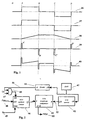
- Fig. 1 illustrates an example unary signal waveform and associated suitable drive waveforms for acoustic transducers with various dynamical properties in order to produce acoustic pulses of approximately square shape;
- Fig. 2 illustrates simplified logic for a digital pulse width modulation (PWM) system for producing linear ramp PWM waveforms from a unary signal and a sign (polarity) signal;
- Fig. 3 illustrates the conventional manner of interconnecting the counters and the magnitude comparator that are components of the system shown in Fig. 2;
- Fig. 4 illustrates typical PWM waveforms produced by the circuit of Fig. 2 with the interconnection pattern shown in Fig. 13;
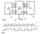
- Fig.5 illustrates an improved method of interconnecting the counters and magnitude comparator of Fig.2; and
- Fig. 6 illustrates the improved PWM waveforms produced by the interconnection pattern of Fig. 5 when applied to the circuit of Fig. 2;
-
- Fig. 1 shows five
electrical waveforms waveform 36 encompasses a period of zero pressure demand between time O and time A, a constant positive pressure demand from time A to time B, a further period of zero pressure demand from B to C, followed by a period of constant negative pressure demand from C to D, and thereafter zero pressure demand. To a first approximation, the transducer diaphragm must move with constant velocity to produce constant pressure, and zero velocity to produce zero pressure, and thereforewaveform 37 is illustrative of the required velocity profile with time for a transducer to produce the pressure profile shown in 36. We make the simplifying assumption here, that is generally true for common transducers, that the input drive voltage or current waveform to the transducer corresponds to the force produced on the transducer diaphragm. - For a transducer where the dominant reaction force on the diaphragm is resistive or viscous due to the resistance of the air being moved in the production of sound, then waveform 37 (which is substantially the same as 36 apart from perhaps scale) represents a suitable force-time profile to achieve the desired pressure waveshape in 36, and in turn is also a suitable electrical drive waveshape, so essentially no pulse shaping is required in this case.
- For a transducer where the dominant reaction force on the diaphragm is a restoring force proportional to the deflection of the diaphragm, as might be produced by a diaphragm suspension, then waveform 38 represents a suitable force-time profile to achieve the desired pressure waveshape in 36, where it will be seen to consist of constant ramp rate sections between A and B, and C and D, of opposite slope, and constant levels of zero slope elsewhere, since such constant ramp rates correspond to linear increases of force, and thus displacement with time, resulting in approximately constant pressure output for these periods.
- For a transducer where the dominant reaction force on the diaphragm is inertial due to the mass of the moving parts of the transducer and entrained air, then waveform 39 represents a suitable force-time profile to achieve the desired pressure waveshape in 36, where at time A a short duration positive driving force terminating at time A' is produced to give a positive impulse of momentum to the transducer's moving mass, after which the mass coasts at approximately constant positive velocity until time B, where it is given a short negative impulse until time B' to bring it quickly to rest again, whereafter at time C a further short negative impulse is given until time C' to give the moving mass a negative impulse of momentum, followed by a further coasting period at substantially constant negative velocity until time D at which a short positive impulse until time D' is applied once more bringing the moving mass to rest.
- For a transducer with mixed dynamics where the dominant forces are some combination of the three identified above, a composite drive waveform, an example of which is shown at 40, comprising some suitable linear combination of
waveforms -
Waveform 38 may be produced with high electrical efficiency by means of pulse-width-modulation (PWM) of a suitably high frequency pulse waveform by a digital pulse width modulation ramp generator, as illustrated in Fig. 2 and which embodies the present invention. - The digital pulse width modulator ramp generator of Fig. 2 comprises a high
frequency clock generator 41, which feeds into the clock input of a k-bitbinary counter 42 with parallel binary output QR at 52 which in turn feeds into one of the two parallel binary inputs (B in this case) of a k-bitbinary magnitude comparator 43. There is also adigital divider 44 connected to theclock 41, the output d of 44 shown as 51 being connected to one of two inputs of an AND-gate 45. - The unary signal Un shown at 47 which is to be shaped as a ramp as shown for example at 38 in Fig. 1, is connected to the other input of the AND
gate 45 with the result that whenever Un is at logic one, clock pulses from d ofdivider 44 issue from the output of the ANDgate 45 from where they are connected to the clock input of k-bit binary up/downcounter 46, and otherwise the output of the AND gate is at logic low. Up/down counter 46 has its up/down control input connected to the sign-bit (or unary sign signal) shown at 48 of the digital loudspeaker circuitry and determines whethercounter 46 will count up when a clock pulse arrives at its input, or count down. - The reset input of
counter 46 is arranged to set the counter to half full count when activated (e.g. if k were equal to 10, so that 46 had a maximum count of 102310 = 11111111112 (binary), then reset might be arranged to set the counter to 51110 = 01111111112) and is connected to an external signal Res shown at 49 which might be issued at times when the desired output signal from the unary output Un is zero. - The k-bit parallel binary output QI of up/down
counter 46 is connected to the parallel binary input A ofcomparator 43, such that the comparator continuously determines the magnitude of the output QI of 46 relative to the magnitude of the output QR of 42, output A>B ofcomparator 43 then being at logic high whenever QI > QR. Details of data synchronization are not shown for simplicity. - The effect of this logic circuitry is that after reset time (i.e. after a Res pulse has been sent to 49 from outside the circuit block) and while Un remains at logic low, the
counter 46 stays static at half-full count while counter 42 cycles throughout its k-bit count range with period P = 2 k /f where f is the frequency ofdigital clock 41, and thus output PWM shown at 50 derived from output A>B of 43, spends precisely half its time at logic low and half at logic high. Thisoutput 50 therefore has period P and mark-space ratio of 1:1. - Starting from this state, when Un goes to logic high, then depending on the state of the Sign input, counter 46 either counts up or down from its initial half full count at a constant rate determined by the divided
clock signal 51 so that its instantaneous output value V available in parallel binary at QI fromcounter 46 is linearly varying with time at a rate of f/D counts per sec, where D is the division ratio ofclock divider 44. If the clock rate f ofcounter 42 is large compared with f/D (i.e. if D»1) then V may be assumed substantially constant over acounter 42 period P, in which case thePWM signal 50 will be high for the fraction V/(2 k -1) of the period P where 0≤V≤(2 k -1), which is exactly the condition required for thesignal 50 to be a linear pulse width modulated representation of value V. It can be shown that even when the condition f » f/D does not hold, that the circuit still produces linear pulse width modulated signals atoutput 50. As the value V increases or decreases linearly with time when Un is at logic one (depending on whether Sign is at logic high or low), the effective value of the PWM output 50 (which is just the time average ofoutput 50 during a period as long as or longer than the period P) is a linear ramp while Un is on and a static value when Un is off, which is precisely the condition required to generate the type of waveform illustrated at 38 in Fig. 1, for driving spring-limited transducers to produce clean square digital acoustic pulse outputs. - In practice additional circuit refinements are useful, one of which is to configure counter 46 as a dead-end counter so that when it reaches either maximum or minimum count it will not roll-over, but instead remain at its terminal count value until the count direction (up or down) reverses and the next clock pulse arrives. This adds significant stability to the PWM generator. It is not essential that the clock input clk on
counter 46 be derived from thesame clock 41 as used forcounter 42 as shown, although this again assists with stability. Additional stability can be achieved in the digital loudspeaker application of this circuit by synchronizingclock 41 with the digital loudspeaker input-data sampling clock, and separately, by driving theRes input 49 high, whenever the input data word value on the control bus represents zero. - Also, for the digital loudspeaker application, it is essential that the full-count period of
counter 46, which is T = 2 k D/f is greater than or equal to the half-period of the lowest frequency audio signal that it is desired to be faithfully reproduced by the speaker, typically 25ms for a 20Hz lower cut-off frequency. In the application of this PWM generator for a digital loudspeaker it should be noted thatcircuit components - It should be noted that this digital method of creating pulse width modulated (PWM) waveforms has applications outside of digital loudspeakers wherever PWM is useful.
- A common requirement of PWM systems is a low pass filter system to reduce the high frequency switching noise in the final output drive waveform. Such low pass filters are more complex and expensive to construct, the closer the PWM clock rate is to the highest modulation frequency required to be reproduced in the low pass filtered output. A method, which uses no extra components, of maximizing this frequency ratio for a PWM generator of the kind illustrated in Fig. 2 is now described.
- Fig. 3 shows in some more detail the conventional method of interconnecting the two
counters magnitude comparator 43, where it will be seen that the least significant bit outputs of thecounters comparator 43 shown as A 0 , A 1 , A 2 , ... and B 0 , B 1 , B 2 , ... and the rest of the bits are connected in the same sequence right through to the most significant bits q k-1 connected to A k-1 and B k-1. This method of connection results in a PWM output waveform at 50 that has a pulse period of 2 k /f where f is the clock frequency ofcounter 42 and k is the number of bits in that counter. As an example, for the simple case where k=3, and where the value (assumed static) represented by the output ofcounter 46 is 1012 = 510 then Fig. 4 shows at 53 the expected waveform atoutput 50 with mark:space ratio of 5:3, and at 51 the clock input signal to counter 42 and marks thecounter 42's count state above each clock pulse as 0, 1, 2, ... 7, 0, etc..Waveform 53 results because whilecounter 42 is in the first fivestates 0 to 4 its output is less than that ofcounter 46 assumed static atvalue 5 in this example, and so the A>B output of the comparator is at logic high for these states, after which it goes low for the rest of thecounter 42's cycle. - In the improved version of the circuit, shown in Fig. 5, it will be seen that the bit order of the connections between the bit outputs of
counter 42 and the bit inputs ofcomparator 43 have been reversed so that the most significant output bit of the counter q k-1 is now connected to the least significant bit input B 0 ofcomparator 43 and this bit-order reversal is carried through for the other bit connections between these devices right through to q 0 connected to B k-1. The effect of this bit reversal is to alter the count sequence seen on the B i (0≤i<k) inputs ofcomparator 43 when viewed in the conventional bit order, with B 0 being the least significant bit of this comparator input. The actual count sequence seen for the previously given example (with k = 3, and wherecounter 46 hasvalue 5 on its outputs) is shown at 54 in Fig. 6. The resulting PWM output from 50 in the modified circuit is shown at 55 in Fig. 6, where it will be seen that whilst it still has the same required average mark-space ratio as the previous arrangement (shown at 53 in Fig. 4) of 5:3, it now consists of three cycles during one period ofcounter 42 rather than just one. This is precisely the effect required to reduce the effort of low pass filtering. - It will be apparent to those versed in the art that this novel technique of raising the effective pulse rate of the PWM output waveform is generally applicable to all applications of pulse width modulation and is not restricted to use in the digital loudspeaker invention presented here.
- Other reorderings of the bit connections between 42 and 43 than the one shown here are useful in this respect but it can be shown that the bit-reversal ordering gives the maximum number of output transitions over the full range of PWM output states. In particular, the bit-reversed ordering produces an output at 50 that transitions on each clock pulse to counter 42 when the
counter 46 is at half-full count, which is the maximum possible output frequency from such a circuit, with 50% or 1:1 mark:space ratio.
Claims (9)
- A digital pulse width modulation generator for pulse width modulating a digital input signal comprising a single data bit and a sign bit, comprising:an up/down digital counter (46), the up/down input of the up/down counter (46) being controlled by the sign bit of the digital input signal;an AND gate (45) having a first input which is clocked continuously by a first clock signal, a second input which receives the data bit of the digital input signal, and an output connected to the clock input of the up/down counter (46);a second digital counter (42) clocked continuously by a constant rate, second clock signal;a digital magnitude comparator (43) which compares the parallel binary outputs of the two counters (42, 46) so that the greater-than or less-than output of the magnitude comparator (43) provides a pulse width modulation output signal, whereby the value represented by the pulse width modulation output signal is a ramp when the data bit of the digital input signal is at logic one and is a static value when the data bit of the digital input signal is at logic zero, the slope of the ramp being determined by the polarity of the sign bit of the digital input signal.
- A digital pulse width modulation generator according to claim 1, wherein the outputs of the two counters (42, 46) are connected to the inputs of the magnitude comparator (43) with the bits of the outputs of the two counters (42, 46) connected to the bits of the inputs of the magnitude comparator (43) in bit significance sequence.
- A digital pulse width modulation generator according to claim 1, wherein
the output of the up/down counter (46) is connected to an input of the magnitude comparator (43) with the bits of the output of the up/down digital counter (46) connected to the bits of the input of the magnitude comparator (43) in bit significance sequence, and
the output of the second counter (42) is connected to an input of the magnitude comparator (43) with the bits in an order other than in bit significance sequence. - A digital pulse width modulation generator according to claim 1,wherein
the output of the up/down counter (46) is connected to an input of the magnitude comparator (43) with the bits of the output of the up/down digital counter (46) connected to the bits of the input of the magnitude comparator (43) in bit significance sequence, and
the output of the second counter (42) is connected to an input of the magnitude comparator (43) with the bits of the output of the second counter (42) connected to the bits of the input of the magnitude comparator (43) in reverse bit significance sequence. - A digital pulse width modulation generator according to any one of the preceding claims, wherein the up/down counter (46) is a dead-end counter.
- A digital pulse width modulation generator according to any one of the preceding claims, wherein the first clock signal is the second clock signal in frequency-divided form.
- A digital pulse width modulation generator according to claim 6, wherein the digital input signal is synchronized with said second clock signal.
- A digital pulse width modulation generator according to any one of claims 1 to 5, wherein the first and second clock signals are derived from different clocks.
- A digital pulse width modulation generator according to any one of the preceding claims, wherein the up/down digital counter (46) has a reset input arranged to set the up/down digital counter (46) to half of the full count.
Applications Claiming Priority (3)
| Application Number | Priority Date | Filing Date | Title |
|---|---|---|---|
| GB9506725 | 1995-03-31 | ||
| GBGB9506725.2A GB9506725D0 (en) | 1995-03-31 | 1995-03-31 | Improvements in or relating to loudspeakers |
| EP96907605A EP0818122B1 (en) | 1995-03-31 | 1996-03-27 | Improvements in or relating to loudspeakers |
Related Parent Applications (1)
| Application Number | Title | Priority Date | Filing Date |
|---|---|---|---|
| EP96907605A Division EP0818122B1 (en) | 1995-03-31 | 1996-03-27 | Improvements in or relating to loudspeakers |
Publications (3)
| Publication Number | Publication Date |
|---|---|
| EP1122973A2 EP1122973A2 (en) | 2001-08-08 |
| EP1122973A3 EP1122973A3 (en) | 2002-09-04 |
| EP1122973B1 true EP1122973B1 (en) | 2005-10-12 |
Family
ID=10772301
Family Applications (2)
| Application Number | Title | Priority Date | Filing Date |
|---|---|---|---|
| EP01108918A Expired - Lifetime EP1122973B1 (en) | 1995-03-31 | 1996-03-27 | Digital pulse-width-modulation generator |
| EP96907605A Expired - Lifetime EP0818122B1 (en) | 1995-03-31 | 1996-03-27 | Improvements in or relating to loudspeakers |
Family Applications After (1)
| Application Number | Title | Priority Date | Filing Date |
|---|---|---|---|
| EP96907605A Expired - Lifetime EP0818122B1 (en) | 1995-03-31 | 1996-03-27 | Improvements in or relating to loudspeakers |
Country Status (10)
| Country | Link |
|---|---|
| US (3) | US6373955B1 (en) |
| EP (2) | EP1122973B1 (en) |
| JP (1) | JP3492698B2 (en) |
| CN (2) | CN1147207C (en) |
| AT (2) | ATE306801T1 (en) |
| AU (1) | AU5117096A (en) |
| DE (2) | DE69618183T2 (en) |
| DK (1) | DK0818122T3 (en) |
| GB (1) | GB9506725D0 (en) |
| WO (1) | WO1996031086A1 (en) |
Cited By (1)
| Publication number | Priority date | Publication date | Assignee | Title |
|---|---|---|---|---|
| US11522448B2 (en) | 2019-05-29 | 2022-12-06 | Alpha And Omega Semiconductor (Cayman) Limited | Autonomous current sharing for power stages |
Families Citing this family (109)
| Publication number | Priority date | Publication date | Assignee | Title |
|---|---|---|---|---|
| GB9506725D0 (en) * | 1995-03-31 | 1995-05-24 | Hooley Anthony | Improvements in or relating to loudspeakers |
| FR2765765B1 (en) * | 1997-07-07 | 2002-12-06 | Pierre Piccaluga | METHOD AND APPARATUS FOR FORMATTING THE DIGITAL AUDIO SIGNAL FOR THE USE OF SOUND REPRODUCTION |
| FR2790353B1 (en) * | 1999-02-25 | 2002-11-15 | Olivier Viacava | AUDIO-DIGITAL SPEAKER CONDUCTING DIGITAL TO ANALOG DIRECTLY INTO THE AIR |
| DE19923170A1 (en) * | 1999-05-21 | 2000-11-23 | Florian M Koenig | Fully digital sound signal supply to sound transducers e.g. for headsets, supplies transducer from digital-to-analogue converter directly and/or via computer-supported digital sound signal processing unit |
| EP1063866B1 (en) * | 1999-05-28 | 2008-11-26 | Texas Instruments Inc. | Digital loudspeaker |
| ATE442705T1 (en) * | 1999-07-19 | 2009-09-15 | Texas Instruments Inc | DIFFERENTIAL MONADIC CODING FOR DIGITAL AUDIO SIGNAL |
| EP1224037B1 (en) * | 1999-09-29 | 2007-10-31 | 1... Limited | Method and apparatus to direct sound using an array of output transducers |
| GB9926489D0 (en) * | 1999-11-10 | 2000-01-12 | New Transducers Ltd | Digital loudspeaker |
| GB0009133D0 (en) * | 2000-04-14 | 2000-05-31 | New Transducers Ltd | Acoustic device and method for driving it |
| DE10026474B4 (en) * | 2000-05-27 | 2005-06-09 | Sennheiser Electronic Gmbh & Co. Kg | Transducer with semiconducting membrane |
| US6895378B1 (en) * | 2000-09-22 | 2005-05-17 | Meyer Sound Laboratories, Incorporated | System and method for producing acoustic response predictions via a communications network |
| US20020055827A1 (en) * | 2000-10-06 | 2002-05-09 | Chris Kyriakakis | Modeling of head related transfer functions for immersive audio using a state-space approach |
| EP1206160A1 (en) * | 2000-11-09 | 2002-05-15 | Texas Instruments Incorporated | Digital loudspeaker |
| US7284256B2 (en) * | 2000-12-04 | 2007-10-16 | Sony Corporation | Method and system to maintain relative statistics for creating automatically a list of favorites |
| US7058463B1 (en) | 2000-12-29 | 2006-06-06 | Nokia Corporation | Method and apparatus for implementing a class D driver and speaker system |
| GB0102865D0 (en) | 2001-02-06 | 2001-03-21 | Secr Defence Brit | Panel form loudspeaker |
| US20020131608A1 (en) * | 2001-03-01 | 2002-09-19 | William Lobb | Method and system for providing digitally focused sound |
| US7515719B2 (en) | 2001-03-27 | 2009-04-07 | Cambridge Mechatronics Limited | Method and apparatus to create a sound field |
| GB0200291D0 (en) * | 2002-01-08 | 2002-02-20 | 1 Ltd | Digital loudspeaker system |
| SE0101720D0 (en) * | 2001-05-16 | 2001-05-16 | Bang & Olufsen Powerhouse As | Apparatus for electric to acoustic conversion |
| GB0124352D0 (en) | 2001-10-11 | 2001-11-28 | 1 Ltd | Signal processing device for acoustic transducer array |
| US7130430B2 (en) * | 2001-12-18 | 2006-10-31 | Milsap Jeffrey P | Phased array sound system |
| JP3671910B2 (en) * | 2002-01-16 | 2005-07-13 | 日産自動車株式会社 | Connection method of rotating electric machine |
| GB0203895D0 (en) * | 2002-02-19 | 2002-04-03 | 1 Ltd | Compact surround-sound system |
| US7184480B1 (en) * | 2002-09-25 | 2007-02-27 | O2Micro International Limited | Digital PWM generator |
| GB0301093D0 (en) * | 2003-01-17 | 2003-02-19 | 1 Ltd | Set-up method for array-type sound systems |
| US20040166817A1 (en) * | 2003-01-20 | 2004-08-26 | Mehran Mokhtari | System, method and apparatus for burst communications |
| US7216248B2 (en) * | 2003-03-20 | 2007-05-08 | Sun Microsystems, Inc. | On-chip clock generator allowing rapid changes of on-chip clock frequency |
| US7929718B1 (en) * | 2003-05-12 | 2011-04-19 | D2Audio Corporation | Systems and methods for switching and mixing signals in a multi-channel amplifier |
| US7684574B2 (en) * | 2003-05-27 | 2010-03-23 | Harman International Industries, Incorporated | Reflective loudspeaker array |
| US7826622B2 (en) * | 2003-05-27 | 2010-11-02 | Harman International Industries, Incorporated | Constant-beamwidth loudspeaker array |
| JP4007255B2 (en) | 2003-06-02 | 2007-11-14 | ヤマハ株式会社 | Array speaker system |
| GB0321676D0 (en) * | 2003-09-16 | 2003-10-15 | 1 Ltd | Digital loudspeaker |
| US8170233B2 (en) * | 2004-02-02 | 2012-05-01 | Harman International Industries, Incorporated | Loudspeaker array system |
| US6822588B1 (en) * | 2004-04-15 | 2004-11-23 | Agilent Technologies, Inc. | Pulse width modulation systems and methods |
| GB0415626D0 (en) * | 2004-07-13 | 2004-08-18 | 1 Ltd | Directional microphone |
| GB0415625D0 (en) * | 2004-07-13 | 2004-08-18 | 1 Ltd | Miniature surround-sound loudspeaker |
| US20070269071A1 (en) * | 2004-08-10 | 2007-11-22 | 1...Limited | Non-Planar Transducer Arrays |
| US7492233B2 (en) * | 2005-04-29 | 2009-02-17 | Honeywell International Inc. | Precision modulated controller output |
| GB0514361D0 (en) * | 2005-07-12 | 2005-08-17 | 1 Ltd | Compact surround sound effects system |
| EP1941729B8 (en) | 2005-10-26 | 2018-10-24 | InterDigital Madison Patent Holdings | A system and method for compensating for a satellite gateway failure |
| US7676049B2 (en) * | 2006-05-12 | 2010-03-09 | Cirrus Logic, Inc. | Reconfigurable audio-video surround sound receiver (AVR) and method |
| US7804972B2 (en) * | 2006-05-12 | 2010-09-28 | Cirrus Logic, Inc. | Method and apparatus for calibrating a sound beam-forming system |
| US7606380B2 (en) * | 2006-04-28 | 2009-10-20 | Cirrus Logic, Inc. | Method and system for sound beam-forming using internal device speakers in conjunction with external speakers |
| US7606377B2 (en) * | 2006-05-12 | 2009-10-20 | Cirrus Logic, Inc. | Method and system for surround sound beam-forming using vertically displaced drivers |
| CN102684699B (en) | 2006-05-21 | 2015-03-18 | 株式会社特瑞君思半导体 | Data conversion apparatus for sound representation |
| WO2007135678A2 (en) * | 2006-05-22 | 2007-11-29 | Audio Pixels Ltd. | Direct digital speaker apparatus having a desired directivity pattern |
| EP2033480B1 (en) * | 2006-05-22 | 2012-07-11 | Audio Pixels Ltd. | Volume and tone control in direct digital speakers |
| US8457338B2 (en) | 2006-05-22 | 2013-06-04 | Audio Pixels Ltd. | Apparatus and methods for generating pressure waves |
| US7570037B2 (en) * | 2006-11-17 | 2009-08-04 | Virginia Tech Intellectual Properties, Inc. | Hybrid control methods for digital pulse width modulator (DPWM) |
| KR101411183B1 (en) * | 2007-05-21 | 2014-06-23 | 오디오 픽셀즈 리미티드 | Direct digital speaker apparatus having a desired directivity pattern |
| DE102007029959A1 (en) * | 2007-06-28 | 2009-01-02 | Robert Bosch Gmbh | Method and device for detecting an environment |
| KR101292206B1 (en) * | 2007-10-01 | 2013-08-01 | 삼성전자주식회사 | Array speaker system and the implementing method thereof |
| EP2846557B1 (en) | 2007-11-21 | 2019-04-10 | Audio Pixels Ltd. | Improved speaker apparatus |
| JP5552620B2 (en) | 2008-06-16 | 2014-07-16 | 株式会社 Trigence Semiconductor | A car equipped with a digital speaker driving device and a centralized control device |
| DE102008038340B4 (en) * | 2008-08-19 | 2010-04-22 | Austriamicrosystems Ag | Circuit arrangement for controlling a light source and method for generating a drive signal for the same |
| EP2326108B1 (en) * | 2009-11-02 | 2015-06-03 | Harman Becker Automotive Systems GmbH | Audio system phase equalizion |
| CN104901693B (en) | 2009-12-09 | 2018-07-10 | 株式会社特瑞君思半导体 | Selection device |
| EP2515555A4 (en) | 2009-12-16 | 2013-08-28 | Trigence Semiconductor Inc | Acoustic system |
| US9391541B2 (en) | 2010-03-11 | 2016-07-12 | Audio Pixels Ltd. | Electrostatic parallel plate actuators whose moving elements are driven only by electrostatic force and methods useful in conjunction therewith |
| CN102316400A (en) * | 2010-07-02 | 2012-01-11 | 英业达股份有限公司 | Horn and portable electronic device adopting same |
| US8693708B2 (en) * | 2010-08-24 | 2014-04-08 | Star Headlight & Lantern Co., Inc. | System for operating a device for producing an audible alarm |
| CN101986721B (en) | 2010-10-22 | 2014-07-09 | 苏州上声电子有限公司 | Fully digital loudspeaker device |
| DK2643982T3 (en) | 2010-11-26 | 2022-07-04 | Audio Pixels Ltd | DEVICE FOR GENERATING A PHYSICAL MEASUREMENT POWER AND METHOD OF MANUFACTURING THE DEVICE |
| DE102011003168A1 (en) * | 2011-01-26 | 2012-07-26 | Robert Bosch Gmbh | Speaker System |
| US20120244969A1 (en) | 2011-03-25 | 2012-09-27 | May Patents Ltd. | System and Method for a Motion Sensing Device |
| TWI461884B (en) * | 2011-04-06 | 2014-11-21 | Himax Imagimg Inc | Clock generating circuit and associated method for generating output clock signal |
| GB2491130B (en) * | 2011-05-23 | 2013-07-10 | Sontia Logic Ltd | Reducing distortion |
| US8897465B2 (en) | 2011-06-01 | 2014-11-25 | Robert Bosch Gmbh | Class D micro-speaker |
| US20130039431A1 (en) * | 2011-08-12 | 2013-02-14 | Electronics And Telecommunications Research Institute | Power-scalable encoding/decoding apparatus and method |
| JP5838927B2 (en) * | 2011-10-14 | 2016-01-06 | Tdk株式会社 | Multilayer ceramic electronic components |
| CN102404672B (en) | 2011-10-27 | 2013-12-18 | 苏州上声电子有限公司 | Method and device for controlling channel equalization and beam of digital loudspeaker array system |
| CN103152673B (en) * | 2011-12-07 | 2015-07-08 | 中国科学院声学研究所 | Digital loudspeaker drive method and device based on quaternary code dynamic mismatch reshaping |
| US9240776B2 (en) * | 2012-01-26 | 2016-01-19 | Rf Micro Devices, Inc. | Analog-digital pulse width modulator (ADPWM) |
| CN103248981B (en) * | 2012-02-06 | 2016-06-01 | 王永明 | A kind of speaker |
| CN102684701B (en) | 2012-04-27 | 2014-07-09 | 苏州上声电子有限公司 | Method and device for driving digital speaker based on code conversion |
| US9880533B2 (en) | 2012-05-25 | 2018-01-30 | Audio Pixels Ltd. | System, a method and a computer program product for controlling a group of actuator arrays for producing a physical effect |
| WO2013175477A1 (en) | 2012-05-25 | 2013-11-28 | Audio Pixels Ltd. | A system, a method and a computer program product for controlling a set of actuator elements |
| US20160050492A1 (en) * | 2013-02-26 | 2016-02-18 | The University Of Akron | Direct-drive digital audio amplifier for electrostatic loudspeakers |
| US8934654B2 (en) | 2013-03-13 | 2015-01-13 | Aliphcom | Non-occluded personal audio and communication system |
| WO2014210530A1 (en) * | 2013-06-28 | 2014-12-31 | Kopin Corporation | Digital voice processing method and system for headset computer |
| US9350336B2 (en) * | 2014-02-05 | 2016-05-24 | Texas Instruments Incorporated | Timing compensation using the system clock |
| CN104022758B (en) * | 2014-05-29 | 2016-09-28 | 中国人民解放军国防科学技术大学 | A kind of band resets the power consumption equilibrium trigger of set port |
| KR102197230B1 (en) * | 2014-10-06 | 2020-12-31 | 한국전자통신연구원 | Audio system and method for predicting acoustic feature |
| KR20170137810A (en) | 2015-04-15 | 2017-12-13 | 오디오 픽셀즈 리미티드 | Method and system for detecting at least the position of an object in space |
| KR102340202B1 (en) | 2015-06-25 | 2021-12-17 | 한국전자통신연구원 | Audio system and method for extracting reflection characteristics |
| US9621040B2 (en) * | 2015-08-20 | 2017-04-11 | Sanken Electric Co., Ltd. | PWM signal generator and switching power supply device having same |
| US10030961B2 (en) | 2015-11-27 | 2018-07-24 | General Electric Company | Gap measuring device |
| EP3390838B1 (en) * | 2015-12-17 | 2021-07-14 | Venturedyne, Ltd | Environmental sensor |
| US10557472B2 (en) | 2015-12-17 | 2020-02-11 | Venturedyne, Ltd. | Environmental sensor and method of operating the same |
| US9857285B2 (en) | 2015-12-17 | 2018-01-02 | Venturedyne, Ltd. | Environmental sensor and method of operating the same |
| US9983596B2 (en) | 2015-12-17 | 2018-05-29 | Venturedyne, Ltd. | Environmental sensor and method of operating the same |
| US9813803B1 (en) * | 2016-05-04 | 2017-11-07 | Wu-Hsu Lin | Electrical speaker assembly |
| US10103928B2 (en) * | 2016-05-23 | 2018-10-16 | National Instruments Corporation | Nyquist and square root nyquist filters for pulse shaping in wireless communications |
| US10014869B1 (en) * | 2017-03-08 | 2018-07-03 | Qualcomm Incorporated | Fractional clock generator with ramp control including fixed time interval and coarse/fine frequency change steps |
| WO2018164438A1 (en) * | 2017-03-10 | 2018-09-13 | Samsung Electronics Co., Ltd. | Method and apparatus for in-room low-frequency sound power optimization |
| US20180315453A1 (en) * | 2017-04-28 | 2018-11-01 | Tymphany Worldwide Enterprises Limited | Audio integrated circuit |
| DE102017221738A1 (en) * | 2017-12-03 | 2019-06-06 | Audi Ag | Method for adjusting power electronics |
| CN107948808A (en) * | 2018-01-12 | 2018-04-20 | 上海联影医疗科技有限公司 | Earphone and magnetic resonance system applied to magnetic resonance system |
| US10951204B2 (en) * | 2018-08-30 | 2021-03-16 | Maxim Integrated Products, Inc. | Digital pulse width modulation driver system |
| US10484784B1 (en) * | 2018-10-19 | 2019-11-19 | xMEMS Labs, Inc. | Sound producing apparatus |
| US10681488B1 (en) | 2019-03-03 | 2020-06-09 | xMEMS Labs, Inc. | Sound producing apparatus and sound producing system |
| US10623882B1 (en) * | 2019-04-03 | 2020-04-14 | xMEMS Labs, Inc. | Sounding system and sounding method |
| US10841136B1 (en) | 2019-08-14 | 2020-11-17 | National Instruments Corporation | Asymmetric factorization of generalized raised cosine filters for improved selectivity |
| US10840895B1 (en) | 2019-09-06 | 2020-11-17 | International Business Machines Corporation | Fine-grained programmable delay and pulse shaping circuit |
| CN111162741B (en) * | 2019-12-23 | 2023-07-25 | 上海船舶电子设备研究所(中国船舶重工集团公司第七二六研究所) | Digital power amplifier and matched filtering method |
| CN111782049B (en) * | 2020-07-02 | 2023-12-01 | 瑞声科技(新加坡)有限公司 | Method and device for evaluating motor application frequency bandwidth and storage medium |
| CN112601155A (en) * | 2020-12-10 | 2021-04-02 | 南京汉得利智能科技有限公司 | Method and system for digital parametric array loudspeaker |
| CN112865731B (en) * | 2021-01-13 | 2023-03-24 | 上海艾为电子技术股份有限公司 | Class D audio amplifier, mixed modulation method thereof and electronic equipment |
Family Cites Families (97)
| Publication number | Priority date | Publication date | Assignee | Title |
|---|---|---|---|---|
| DE966384C (en) | 1949-05-29 | 1957-08-01 | Siemens Ag | Electroacoustic transmission system with a loudspeaker arrangement in a playback room |
| US3996561A (en) * | 1974-04-23 | 1976-12-07 | Honeywell Information Systems, Inc. | Priority determination apparatus for serially coupled peripheral interfaces in a data processing system |
| US3992586A (en) * | 1975-11-13 | 1976-11-16 | Jaffe Acoustics, Inc. | Boardroom sound reinforcement system |
| US4042778A (en) * | 1976-04-01 | 1977-08-16 | Clinton Henry H | Collapsible speaker assembly |
| GB1603201A (en) | 1977-03-11 | 1981-11-18 | Ard Tech Ass Eng | Sound reproduction systems |
| GB1571714A (en) | 1977-04-13 | 1980-07-16 | Kef Electronics Ltd | Loudspeakers |
| US4190739A (en) * | 1977-04-27 | 1980-02-26 | Marvin Torffield | High-fidelity stereo sound system |
| EP0025118A1 (en) | 1979-08-18 | 1981-03-18 | Riedlinger, Rainer, Dr.-Ing. | Arrangement for the acoustic reproduction of signals, presented by means of a right and a left stereo-channel |
| US4330691A (en) * | 1980-01-31 | 1982-05-18 | The Futures Group, Inc. | Integral ceiling tile-loudspeaker system |
| US4305296B2 (en) * | 1980-02-08 | 1989-05-09 | Ultrasonic imaging method and apparatus with electronic beam focusing and scanning | |
| US4769848A (en) * | 1980-05-05 | 1988-09-06 | Howard Krausse | Electroacoustic network |
| JPS5768991A (en) * | 1980-10-16 | 1982-04-27 | Pioneer Electronic Corp | Speaker system |
| DE3142462A1 (en) | 1980-10-28 | 1982-05-27 | Hans-Peter 7000 Stuttgart Pfeiffer | Loudspeaker device |
| US4388493A (en) * | 1980-11-28 | 1983-06-14 | Maisel Douglas A | In-band signaling system for FM transmission systems |
| US4515997A (en) * | 1982-09-23 | 1985-05-07 | Stinger Jr Walter E | Direct digital loudspeaker |
| JPS59179743A (en) | 1983-03-31 | 1984-10-12 | Showa Electric Wire & Cable Co Ltd | Copper alloy for electric conduction with superior bending resistance |
| JPS59186498A (en) | 1983-04-07 | 1984-10-23 | Nippon Columbia Co Ltd | Parametric array microphone |
| JPS60249946A (en) * | 1984-05-25 | 1985-12-10 | 株式会社東芝 | Ultrasonic tissue diagnostic method and apparatus |
| JPH0728463B2 (en) | 1984-08-28 | 1995-03-29 | 松下電器産業株式会社 | Parametric speaker |
| JPS61253996A (en) | 1985-05-02 | 1986-11-11 | Matsushita Electric Ind Co Ltd | Parametric speaker |
| JPH0239997B2 (en) | 1984-12-26 | 1990-09-07 | Takao Shishido | NIJIKYOKUSENSOSEIGU |
| DE3533264A1 (en) | 1985-09-18 | 1987-03-26 | Meier F Victoria Pinsel | DEVICE FOR DENTAL CARE |
| JPH0815288B2 (en) | 1985-09-30 | 1996-02-14 | 株式会社東芝 | Audio transmission system |
| JPS62103315A (en) | 1985-10-30 | 1987-05-13 | Yoshikawa Kogyo Co Ltd | Hearth roll for heat treating furnace |
| JPH0679195B2 (en) | 1985-12-04 | 1994-10-05 | 大日本印刷株式会社 | Hologram transfer sheet with picture |
| JPS639300A (en) | 1986-06-27 | 1988-01-14 | Matsushita Electric Ind Co Ltd | Speaker system |
| JPS6314588A (en) | 1986-07-07 | 1988-01-21 | Toshiba Corp | Electronic conference system |
| JP2713402B2 (en) | 1987-03-23 | 1998-02-16 | 松下電器産業株式会社 | Sound field correction device |
| US4773096A (en) * | 1987-07-20 | 1988-09-20 | Kirn Larry J | Digital switching power amplifier |
| GB2209229B (en) | 1987-08-28 | 1991-12-04 | Tasco Ltd | Remote control system |
| KR910007182B1 (en) | 1987-12-21 | 1991-09-19 | 마쯔시다덴기산교 가부시기가이샤 | Screen apparatus |
| FR2628335B1 (en) | 1988-03-09 | 1991-02-15 | Univ Alsace | INSTALLATION FOR PROVIDING THE CONTROL OF SOUND, LIGHT AND / OR OTHER PHYSICAL EFFECTS OF A SHOW |
| NL8800858A (en) | 1988-04-05 | 1989-11-01 | Philips Nv | CALCULATOR SYSTEM EQUIPPED WITH A MAIN BUS AND BETWEEN PROCESSOR AND MEMORY CONTAINING CONNECTED EXTRA COMMUNICATION LINE. |
| JPH01297716A (en) | 1988-05-26 | 1989-11-30 | Toyobo Co Ltd | Optical coordinate input device |
| US5016258A (en) * | 1988-06-10 | 1991-05-14 | Matsushita Electric Industrial Co., Ltd. | Digital modulator and demodulator |
| JPH0213097A (en) | 1988-06-29 | 1990-01-17 | Toa Electric Co Ltd | Drive control device for loudspeaker system |
| FI81471C (en) * | 1988-11-08 | 1990-10-10 | Timo Tarkkonen | HOEGTALARE GIVANDE ETT TREDIMENSIONELLT STEREOLJUDINTRYCK. |
| US4984273A (en) * | 1988-11-21 | 1991-01-08 | Bose Corporation | Enhancing bass |
| US4961432A (en) | 1989-01-10 | 1990-10-09 | Cancer Diagnostics, Inc. | Modular fluid sample preparation assembly |
| US5051799A (en) * | 1989-02-17 | 1991-09-24 | Paul Jon D | Digital output transducer |
| JP2610991B2 (en) | 1989-03-13 | 1997-05-14 | ティーオーエー株式会社 | Directivity control type speaker system |
| JPH034842A (en) | 1989-05-31 | 1991-01-10 | Aloka Co Ltd | Ultrasonic doppler diagnostic device |
| US4980871A (en) * | 1989-08-22 | 1990-12-25 | Visionary Products, Inc. | Ultrasonic tracking system |
| US4972381A (en) * | 1989-09-29 | 1990-11-20 | Westinghouse Electric Corp. | Sonar testing apparatus |
| AT394124B (en) | 1989-10-23 | 1992-02-10 | Goerike Rudolf | TELEVISION RECEIVER WITH STEREO SOUND PLAYBACK |
| JP2665007B2 (en) | 1989-11-16 | 1997-10-22 | 三菱重工業株式会社 | Super directional speaker system |
| JP3067140B2 (en) | 1989-11-17 | 2000-07-17 | 日本放送協会 | 3D sound reproduction method |
| JPH0736866B2 (en) * | 1989-11-28 | 1995-04-26 | ヤマハ株式会社 | Hall sound field support device |
| JPH03252315A (en) | 1990-02-27 | 1991-11-11 | Osaka Titanium Co Ltd | Production of high-purity titanium oxide |
| GB2243040A (en) | 1990-04-09 | 1991-10-16 | William Stuart Hickie Taylor | Radio / sonic transponder location system |
| JPH048975A (en) | 1990-04-24 | 1992-01-13 | Tokimec Inc | Controller loading type electromagnetic control valve |
| JP2848918B2 (en) | 1990-05-14 | 1999-01-20 | 住友ベークライト株式会社 | Resin for double-sided flexible printed circuit boards. |
| JPH04214144A (en) | 1990-07-10 | 1992-08-05 | Mitsui Constr Co Ltd | Damper for exhaust gas duct |
| JPH04127700A (en) | 1990-09-18 | 1992-04-28 | Matsushita Electric Ind Co Ltd | Image controller |
| US5287531A (en) * | 1990-10-31 | 1994-02-15 | Compaq Computer Corp. | Daisy-chained serial shift register for determining configuration of removable circuit boards in a computer system |
| EP0492015A1 (en) | 1990-12-28 | 1992-07-01 | Uraco Impex Asia Pte Ltd. | Method and apparatus for navigating an automatic guided vehicle |
| JP3052384B2 (en) | 1991-01-21 | 2000-06-12 | 三菱電機株式会社 | Multi-amplifier speaker system |
| JPH051321A (en) | 1991-06-24 | 1993-01-08 | Daido Steel Co Ltd | Production of high strength bolt excellent in delayed fracture resistance and fatigue characteristic |
| JPH0510123A (en) | 1991-06-28 | 1993-01-19 | Kubota Corp | Forcibly air cooling device for engine |
| JPH0541897A (en) * | 1991-08-07 | 1993-02-19 | Pioneer Electron Corp | Speaker equipment and directivity control method |
| EP0598809B1 (en) | 1991-08-15 | 1999-02-24 | Hein-Werner Corporation | Vehicle shape determination system |
| JP3369200B2 (en) | 1991-09-30 | 2003-01-20 | 日本放送協会 | Multi-channel stereo playback system |
| US5166905A (en) * | 1991-10-21 | 1992-11-24 | Texaco Inc. | Means and method for dynamically locating positions on a marine seismic streamer cable |
| JP3211321B2 (en) | 1992-01-20 | 2001-09-25 | 松下電器産業株式会社 | Directional speaker device |
| JP2827652B2 (en) | 1992-01-22 | 1998-11-25 | 松下電器産業株式会社 | Sound reproduction system |
| JPH05301465A (en) | 1992-02-26 | 1993-11-16 | Ricoh Co Ltd | Sublimation type thermal transfer image receiving material |
| JPH05344584A (en) | 1992-06-12 | 1993-12-24 | Matsushita Electric Ind Co Ltd | Acoustic device |
| US5313300A (en) * | 1992-08-10 | 1994-05-17 | Commodore Electronics Limited | Binary to unary decoder for a video digital to analog converter |
| JPH0662488A (en) | 1992-08-11 | 1994-03-04 | Pioneer Electron Corp | Speaker equipment |
| US5550726A (en) | 1992-10-08 | 1996-08-27 | Ushio U-Tech Inc. | Automatic control system for lighting projector |
| JPH06178379A (en) | 1992-12-10 | 1994-06-24 | Sony Corp | Video visuality system |
| US5313172A (en) * | 1992-12-11 | 1994-05-17 | Rockwell International Corporation | Digitally switched gain amplifier for digitally controlled automatic gain control amplifier applications |
| FR2699205B1 (en) * | 1992-12-11 | 1995-03-10 | Decaux Jean Claude | Improvements to methods and devices for protecting a given volume from outside noise, preferably located inside a room. |
| JP3205625B2 (en) | 1993-01-07 | 2001-09-04 | パイオニア株式会社 | Speaker device |
| JPH06225379A (en) | 1993-01-25 | 1994-08-12 | Matsushita Electric Ind Co Ltd | Directional speaker device |
| JPH077788A (en) * | 1993-03-19 | 1995-01-10 | Ford Motor Co | Sound reproduction system and sound reproduction method |
| WO1994023351A1 (en) | 1993-04-03 | 1994-10-13 | Cat Systems Limited | Localising system |
| JPH06318087A (en) | 1993-05-07 | 1994-11-15 | Mitsui Constr Co Ltd | Method and device for controlling sound for stage |
| JP3293240B2 (en) | 1993-05-18 | 2002-06-17 | ヤマハ株式会社 | Digital signal processor |
| JP2702876B2 (en) | 1993-09-08 | 1998-01-26 | 株式会社石川製作所 | Sound source detection device |
| DE4428500C2 (en) | 1993-09-23 | 2003-04-24 | Siemens Ag | Ultrasonic transducer array with a reduced number of transducer elements |
| US5751821A (en) * | 1993-10-28 | 1998-05-12 | Mcintosh Laboratory, Inc. | Speaker system with reconfigurable, high-frequency dispersion pattern |
| JPH07154893A (en) | 1993-12-01 | 1995-06-16 | Nippon Hoso Kyokai <Nhk> | Speaker system |
| DE4343807A1 (en) * | 1993-12-22 | 1995-06-29 | Guenther Nubert Elektronic Gmb | Digital loudspeaker array for electric-to-acoustic signal conversion |
| JPH07203581A (en) | 1993-12-29 | 1995-08-04 | Matsushita Electric Ind Co Ltd | Directional speaker system |
| GB2290380A (en) | 1994-05-13 | 1995-12-20 | Gd Eng Ass | Shot tracking device |
| US5517200A (en) * | 1994-06-24 | 1996-05-14 | The United States Of America As Represented By The Secretary Of The Air Force | Method for detecting and assessing severity of coordinated failures in phased array antennas |
| NL9401860A (en) * | 1994-11-08 | 1996-06-03 | Duran Bv | Loudspeaker system with controlled directivity. |
| GB9506725D0 (en) * | 1995-03-31 | 1995-05-24 | Hooley Anthony | Improvements in or relating to loudspeakers |
| US5763785A (en) * | 1995-06-29 | 1998-06-09 | Massachusetts Institute Of Technology | Integrated beam forming and focusing processing circuit for use in an ultrasound imaging system |
| GB2320351B (en) | 1995-09-05 | 1999-09-29 | Ryford Ltd | Flow control means |
| US5832097A (en) * | 1995-09-19 | 1998-11-03 | Gennum Corporation | Multi-channel synchronous companding system |
| US6205224B1 (en) | 1996-05-17 | 2001-03-20 | The Boeing Company | Circularly symmetric, zero redundancy, planar array having broad frequency range applications |
| DE19920307A1 (en) * | 1999-05-03 | 2000-11-16 | St Microelectronics Gmbh | Electrical circuit for controlling a load |
| US7260235B1 (en) | 2000-10-16 | 2007-08-21 | Bose Corporation | Line electroacoustical transducing |
| US7515719B2 (en) * | 2001-03-27 | 2009-04-07 | Cambridge Mechatronics Limited | Method and apparatus to create a sound field |
| GB0203895D0 (en) * | 2002-02-19 | 2002-04-03 | 1 Ltd | Compact surround-sound system |
-
1995
- 1995-03-31 GB GBGB9506725.2A patent/GB9506725D0/en active Pending
-
1996
- 1996-03-27 WO PCT/GB1996/000736 patent/WO1996031086A1/en active IP Right Grant
- 1996-03-27 AT AT01108918T patent/ATE306801T1/en not_active IP Right Cessation
- 1996-03-27 CN CNB96193039XA patent/CN1147207C/en not_active Expired - Fee Related
- 1996-03-27 CN CN200410006846.2A patent/CN1575037A/en active Pending
- 1996-03-27 JP JP52907696A patent/JP3492698B2/en not_active Expired - Fee Related
- 1996-03-27 DK DK96907605T patent/DK0818122T3/en active
- 1996-03-27 DE DE69618183T patent/DE69618183T2/en not_active Expired - Fee Related
- 1996-03-27 EP EP01108918A patent/EP1122973B1/en not_active Expired - Lifetime
- 1996-03-27 US US08/930,360 patent/US6373955B1/en not_active Expired - Lifetime
- 1996-03-27 AT AT96907605T patent/ATE211345T1/en not_active IP Right Cessation
- 1996-03-27 DE DE69635286T patent/DE69635286D1/en not_active Expired - Lifetime
- 1996-03-27 EP EP96907605A patent/EP0818122B1/en not_active Expired - Lifetime
- 1996-03-27 AU AU51170/96A patent/AU5117096A/en not_active Abandoned
-
2001
- 2001-05-02 US US09/848,752 patent/US6967541B2/en not_active Expired - Fee Related
-
2005
- 2005-08-18 US US11/207,110 patent/US7215788B2/en not_active Expired - Fee Related
Cited By (1)
| Publication number | Priority date | Publication date | Assignee | Title |
|---|---|---|---|---|
| US11522448B2 (en) | 2019-05-29 | 2022-12-06 | Alpha And Omega Semiconductor (Cayman) Limited | Autonomous current sharing for power stages |
Also Published As
| Publication number | Publication date |
|---|---|
| CN1180470A (en) | 1998-04-29 |
| EP1122973A3 (en) | 2002-09-04 |
| DE69618183T2 (en) | 2002-08-14 |
| GB9506725D0 (en) | 1995-05-24 |
| DE69618183D1 (en) | 2002-01-31 |
| ATE211345T1 (en) | 2002-01-15 |
| DE69635286D1 (en) | 2006-02-23 |
| US6967541B2 (en) | 2005-11-22 |
| EP0818122B1 (en) | 2001-12-19 |
| US20060049889A1 (en) | 2006-03-09 |
| US20010043652A1 (en) | 2001-11-22 |
| US7215788B2 (en) | 2007-05-08 |
| WO1996031086A1 (en) | 1996-10-03 |
| JPH11502981A (en) | 1999-03-09 |
| ATE306801T1 (en) | 2005-10-15 |
| CN1147207C (en) | 2004-04-21 |
| JP3492698B2 (en) | 2004-02-03 |
| DK0818122T3 (en) | 2002-03-18 |
| CN1575037A (en) | 2005-02-02 |
| EP0818122A1 (en) | 1998-01-14 |
| AU5117096A (en) | 1996-10-16 |
| US6373955B1 (en) | 2002-04-16 |
| EP1122973A2 (en) | 2001-08-08 |
Similar Documents
| Publication | Publication Date | Title |
|---|---|---|
| EP1122973B1 (en) | Digital pulse-width-modulation generator | |
| CN1608393B (en) | High efficiency driver for miniature loudspeakers | |
| US5198818A (en) | Oversampled digital-to-analog converter for multilevel data transmission | |
| US5337338A (en) | Pulse density modulation circuit (parallel to serial) comparing in a nonsequential bit order | |
| JP3577321B2 (en) | Digital-to-analog converter with multiple output stages | |
| US6429737B1 (en) | Method and apparatus for multi-channel digital amplification | |
| EP1985018B1 (en) | Systems and methods for pulse width modulating asymmetric signal levels | |
| US5243346A (en) | Digital-to-analog converting device using decoders and parallel-to-serial converters | |
| US7215272B2 (en) | Schemes to implement multi-level PWM in digital system | |
| TW453045B (en) | Multi-level pulse width modulation device and its control structure | |
| US20040223545A1 (en) | Multi-level pulse width modulation in digital system | |
| EP0367522A2 (en) | Closed loop pulse width analog-to-digital converter | |
| US5270633A (en) | Ternary energy supply circuit with a high frequency rejection filter | |
| GB2177565A (en) | Digital signal processing device working with continuous bit streams | |
| JP3029625B2 (en) | Pulse width modulation circuit | |
| US5357248A (en) | Sampling rate converter | |
| CN102823128B (en) | Digital amplifier | |
| JP2674648B2 (en) | Pulse width modulation signal generator | |
| JPS60100830A (en) | Digital/analog converter | |
| JP2000134944A (en) | Phase locked loop and digital pulse-width modulation power controller | |
| JPH0222927A (en) | Noise reduction circuit for digital modulation | |
| JPH06311038A (en) | Feedback pulse width modulation a/d converter | |
| JPS6387017A (en) | Demodulator for pulse modulation data | |
| JPH07123061A (en) | Transmission method for audio signal and transmitter-receiver | |
| JPS62128213A (en) | Digital-analog converter |
Legal Events
| Date | Code | Title | Description |
|---|---|---|---|
| PUAI | Public reference made under article 153(3) epc to a published international application that has entered the european phase |
Free format text: ORIGINAL CODE: 0009012 |
|
| AC | Divisional application: reference to earlier application |
Ref document number: 818122 Country of ref document: EP |
|
| AK | Designated contracting states |
Kind code of ref document: A2 Designated state(s): AT BE CH DE DK ES FI FR GB GR IE IT LI LU MC NL PT SE |
|
| RAP1 | Party data changed (applicant data changed or rights of an application transferred) |
Owner name: 1... LIMITED |
|
| RAP1 | Party data changed (applicant data changed or rights of an application transferred) |
Owner name: 1... LIMITED |
|
| PUAL | Search report despatched |
Free format text: ORIGINAL CODE: 0009013 |
|
| AK | Designated contracting states |
Kind code of ref document: A3 Designated state(s): AT BE CH DE DK ES FI FR GB GR IE IT LI LU MC NL PT SE |
|
| RIC1 | Information provided on ipc code assigned before grant |
Free format text: 7H 04R 5/04 A, 7H 04R 1/40 B, 7H 04R 1/00 B |
|
| 17P | Request for examination filed |
Effective date: 20030303 |
|
| AKX | Designation fees paid |
Designated state(s): AT BE CH DE DK ES FI FR GB GR IE IT LI LU MC NL PT SE |
|
| 17Q | First examination report despatched |
Effective date: 20030714 |
|
| GRAP | Despatch of communication of intention to grant a patent |
Free format text: ORIGINAL CODE: EPIDOSNIGR1 |
|
| GRAS | Grant fee paid |
Free format text: ORIGINAL CODE: EPIDOSNIGR3 |
|
| GRAA | (expected) grant |
Free format text: ORIGINAL CODE: 0009210 |
|
| AC | Divisional application: reference to earlier application |
Ref document number: 0818122 Country of ref document: EP Kind code of ref document: P |
|
| AK | Designated contracting states |
Kind code of ref document: B1 Designated state(s): AT BE CH DE DK ES FI FR GB GR IE IT LI LU MC NL PT SE |
|
| PG25 | Lapsed in a contracting state [announced via postgrant information from national office to epo] |
Ref country code: IT Free format text: LAPSE BECAUSE OF FAILURE TO SUBMIT A TRANSLATION OF THE DESCRIPTION OR TO PAY THE FEE WITHIN THE PRESCRIBED TIME-LIMIT;WARNING: LAPSES OF ITALIAN PATENTS WITH EFFECTIVE DATE BEFORE 2007 MAY HAVE OCCURRED AT ANY TIME BEFORE 2007. THE CORRECT EFFECTIVE DATE MAY BE DIFFERENT FROM THE ONE RECORDED. Effective date: 20051012 Ref country code: NL Free format text: LAPSE BECAUSE OF FAILURE TO SUBMIT A TRANSLATION OF THE DESCRIPTION OR TO PAY THE FEE WITHIN THE PRESCRIBED TIME-LIMIT Effective date: 20051012 Ref country code: LI Free format text: LAPSE BECAUSE OF FAILURE TO SUBMIT A TRANSLATION OF THE DESCRIPTION OR TO PAY THE FEE WITHIN THE PRESCRIBED TIME-LIMIT Effective date: 20051012 Ref country code: BE Free format text: LAPSE BECAUSE OF FAILURE TO SUBMIT A TRANSLATION OF THE DESCRIPTION OR TO PAY THE FEE WITHIN THE PRESCRIBED TIME-LIMIT Effective date: 20051012 Ref country code: AT Free format text: LAPSE BECAUSE OF FAILURE TO SUBMIT A TRANSLATION OF THE DESCRIPTION OR TO PAY THE FEE WITHIN THE PRESCRIBED TIME-LIMIT Effective date: 20051012 Ref country code: FI Free format text: LAPSE BECAUSE OF FAILURE TO SUBMIT A TRANSLATION OF THE DESCRIPTION OR TO PAY THE FEE WITHIN THE PRESCRIBED TIME-LIMIT Effective date: 20051012 Ref country code: CH Free format text: LAPSE BECAUSE OF FAILURE TO SUBMIT A TRANSLATION OF THE DESCRIPTION OR TO PAY THE FEE WITHIN THE PRESCRIBED TIME-LIMIT Effective date: 20051012 |
|
| REG | Reference to a national code |
Ref country code: GB Ref legal event code: FG4D |
|
| REG | Reference to a national code |
Ref country code: CH Ref legal event code: EP |
|
| REG | Reference to a national code |
Ref country code: IE Ref legal event code: FG4D |
|
| PG25 | Lapsed in a contracting state [announced via postgrant information from national office to epo] |
Ref country code: GR Free format text: LAPSE BECAUSE OF FAILURE TO SUBMIT A TRANSLATION OF THE DESCRIPTION OR TO PAY THE FEE WITHIN THE PRESCRIBED TIME-LIMIT Effective date: 20060112 Ref country code: DK Free format text: LAPSE BECAUSE OF FAILURE TO SUBMIT A TRANSLATION OF THE DESCRIPTION OR TO PAY THE FEE WITHIN THE PRESCRIBED TIME-LIMIT Effective date: 20060112 Ref country code: SE Free format text: LAPSE BECAUSE OF FAILURE TO SUBMIT A TRANSLATION OF THE DESCRIPTION OR TO PAY THE FEE WITHIN THE PRESCRIBED TIME-LIMIT Effective date: 20060112 |
|
| PG25 | Lapsed in a contracting state [announced via postgrant information from national office to epo] |
Ref country code: DE Free format text: LAPSE BECAUSE OF FAILURE TO SUBMIT A TRANSLATION OF THE DESCRIPTION OR TO PAY THE FEE WITHIN THE PRESCRIBED TIME-LIMIT Effective date: 20060113 |
|
| PG25 | Lapsed in a contracting state [announced via postgrant information from national office to epo] |
Ref country code: ES Free format text: LAPSE BECAUSE OF FAILURE TO SUBMIT A TRANSLATION OF THE DESCRIPTION OR TO PAY THE FEE WITHIN THE PRESCRIBED TIME-LIMIT Effective date: 20060123 |
|
| REF | Corresponds to: |
Ref document number: 69635286 Country of ref document: DE Date of ref document: 20060223 Kind code of ref document: P |
|
| PG25 | Lapsed in a contracting state [announced via postgrant information from national office to epo] |
Ref country code: PT Free format text: LAPSE BECAUSE OF FAILURE TO SUBMIT A TRANSLATION OF THE DESCRIPTION OR TO PAY THE FEE WITHIN THE PRESCRIBED TIME-LIMIT Effective date: 20060313 |
|
| PG25 | Lapsed in a contracting state [announced via postgrant information from national office to epo] |
Ref country code: IE Free format text: LAPSE BECAUSE OF NON-PAYMENT OF DUE FEES Effective date: 20060327 |
|
| PG25 | Lapsed in a contracting state [announced via postgrant information from national office to epo] |
Ref country code: MC Free format text: LAPSE BECAUSE OF NON-PAYMENT OF DUE FEES Effective date: 20060331 Ref country code: LU Free format text: LAPSE BECAUSE OF NON-PAYMENT OF DUE FEES Effective date: 20060331 |
|
| NLV1 | Nl: lapsed or annulled due to failure to fulfill the requirements of art. 29p and 29m of the patents act | ||
| REG | Reference to a national code |
Ref country code: CH Ref legal event code: PL |
|
| PLBE | No opposition filed within time limit |
Free format text: ORIGINAL CODE: 0009261 |
|
| STAA | Information on the status of an ep patent application or granted ep patent |
Free format text: STATUS: NO OPPOSITION FILED WITHIN TIME LIMIT |
|
| 26N | No opposition filed |
Effective date: 20060713 |
|
| PG25 | Lapsed in a contracting state [announced via postgrant information from national office to epo] |
Ref country code: FR Free format text: LAPSE BECAUSE OF FAILURE TO SUBMIT A TRANSLATION OF THE DESCRIPTION OR TO PAY THE FEE WITHIN THE PRESCRIBED TIME-LIMIT Effective date: 20061020 |
|
| EN | Fr: translation not filed | ||
| REG | Reference to a national code |
Ref country code: IE Ref legal event code: MM4A |
|
| PG25 | Lapsed in a contracting state [announced via postgrant information from national office to epo] |
Ref country code: FR Free format text: LAPSE BECAUSE OF FAILURE TO SUBMIT A TRANSLATION OF THE DESCRIPTION OR TO PAY THE FEE WITHIN THE PRESCRIBED TIME-LIMIT Effective date: 20051012 |
|
| REG | Reference to a national code |
Ref country code: GB Ref legal event code: 732E Free format text: REGISTERED BETWEEN 20130905 AND 20130911 |
|
| PGFP | Annual fee paid to national office [announced via postgrant information from national office to epo] |
Ref country code: GB Payment date: 20140326 Year of fee payment: 19 |
|
| GBPC | Gb: european patent ceased through non-payment of renewal fee |
Effective date: 20150327 |
|
| PG25 | Lapsed in a contracting state [announced via postgrant information from national office to epo] |
Ref country code: GB Free format text: LAPSE BECAUSE OF NON-PAYMENT OF DUE FEES Effective date: 20150327 |