EP0766477A2 - Système de transmission avec dispositifs de tranfert pour réduire les effets d'interférence - Google Patents
Système de transmission avec dispositifs de tranfert pour réduire les effets d'interférence Download PDFInfo
- Publication number
- EP0766477A2 EP0766477A2 EP96440074A EP96440074A EP0766477A2 EP 0766477 A2 EP0766477 A2 EP 0766477A2 EP 96440074 A EP96440074 A EP 96440074A EP 96440074 A EP96440074 A EP 96440074A EP 0766477 A2 EP0766477 A2 EP 0766477A2
- Authority
- EP
- European Patent Office
- Prior art keywords
- connection
- signal
- signals
- transmission system
- transfer device
- Prior art date
- Legal status (The legal status is an assumption and is not a legal conclusion. Google has not performed a legal analysis and makes no representation as to the accuracy of the status listed.)
- Ceased
Links
Images
Classifications
-
- H—ELECTRICITY
- H04—ELECTRIC COMMUNICATION TECHNIQUE
- H04N—PICTORIAL COMMUNICATION, e.g. TELEVISION
- H04N7/00—Television systems
- H04N7/16—Analogue secrecy systems; Analogue subscription systems
- H04N7/173—Analogue secrecy systems; Analogue subscription systems with two-way working, e.g. subscriber sending a programme selection signal
- H04N7/17309—Transmission or handling of upstream communications
Definitions
- the invention relates to a transmission system according to the preamble of claim 1.
- the invention also relates to a transfer device for such a transmission system and a device for directionally dependent attenuation of signals.
- the transfer device is the subject of claim 7 and the device for direction-dependent attenuation of signals is the subject of claim 8.
- a transmission system is e.g. B. a broadband distribution network, which is known from H. Hessenmüller et al, "Access Network Structures for Interactive Video Services", Part 1, The Telecommunications Engineer, Volume 48, August 1994.
- BK networks broadband distribution networks, which are also referred to as BK networks.
- BK repeater station In a higher-level BK repeater station, all television and radio programs are combined into a uniform range of programs and distributed to the user-supplied BK repeater stations, which are usually located in local exchanges. From the BK repeater stations, the television and radio programs are distributed downwards to the participants.
- Such a BK network represents a public network that ends at transfer facilities, which are also referred to as house transfer points.
- transfer facilities which are also referred to as house transfer points.
- One or more subscriber terminals can be connected to each transfer device that is usually located in a house via a private internal network.
- SoD Service-on-Demand
- VoD video-on-demand
- back channels are provided in a BK network for signal transmission in the upward direction. This enables subscribers to the SoD exchange to send user data in order to, for. B. Request information.
- the subscriber terminals have additional devices for interactive services, such additional devices are also referred to as set-top boxes.
- a frequency range of approx. 5 - 30 MHz is defined for the return channels (upward signals) and a frequency range of approx. 40 - 300 MHz (450 MHz, hyperband) for the television and radio signals (downward signals).
- the private in-house network is exposed to numerous disruptions, e.g. B. caused by short wave broadcast transmitters, amateur radio equipment and electrical machines.
- some of the cables in the in-house network are designed regardless of such sources of interference.
- the upward signals are particularly disturbed by the interference.
- This problem is known, e.g. B. from N. De Muynck et al, "CATV-cables, they can do more!, International Television Symposium, Montreux, Switzerland, June 15, 1991, pages 179 to 195.
- By a combination of high and low pass filters prevents upward signals with a high signal level from interfering with the downward signals. This is also to prevent the interference superimposed on the uplink signals in the in-house network, ie within the house, from influencing or even interrupting the transmission.
- the invention is based on the object of specifying a transmission system in which upward signals can be received and evaluated by a center, although interference has been superimposed on the upward signals in private in-house networks.
- a transmission system that solves the problem is the subject of claim 1.
- a transfer device for such a transmission system is the subject of claim 7 and a device for directionally dependent attenuation of signals is the subject of claim 8.
- Advantageous embodiments of the invention are specified in the subclaims.
- An advantage of the invention is that the transfer device is a passive device, so that no voltage supply is necessary at the location of the transfer device. It is also advantageous that the transfer device without great effort to local conditions, such. B. can be adjusted to the amount of the local interference level.
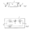
- the device 1 shows a basic circuit diagram of a device 1 for direction-dependent attenuation of signals in order to explain the basic idea of the invention. Following this, the use of such a device 1 for directionally dependent attenuation of signals in a transmission system is explained.
- the device 1 has two connections 2, 3 through which the device 1 can be inserted into a line section L. 3, the line section L is a transmission path, a coaxial cable is preferably used for this.
- a signal can be supplied to connection 2, which is referred to as downward signal AB for the following description.
- a signal can also be fed to the terminal 3, which is referred to below as an upward signal UP.
- the downward signal AB is supplied to the terminal 3 as undamped as possible, and the upward signal UP is supplied to the terminal 2 in an attenuated manner with a fixed damping factor a.
- Fig. 1 the directions of propagation of the up and down signal UP, DOWN are indicated by arrows.
- FIG. 2 shows a block diagram of the device 1 shown in FIG. 1 for direction-dependent attenuation of signals.
- a first branch which is connected at one end to connection 2 and at a second end to connection 3, there are frequency-selective elements, preferably two low-pass filters 4, 6, which are part of a crossover network, and an adjustable attenuator 5 is connected in series.
- two low-pass filters 4, 6, it is possible to insert only a single low-pass filter in the first branch.
- a second branch which is connected in parallel with the first branch and is therefore also connected to the two connections 2, 3, there is a high-pass filter 7 which is part of a crossover network.
- the up signal UP and the down signal AB usually occupy different frequency ranges: the down signal AB (television and radio signals) has frequencies in the range between 40-300 MHz (450 MHz, hyperband) and the up signal UP has frequencies in the range between 5 - 30 MHz.
- the high-pass filter 7 is designed so that the frequency range of the down signal AB is let through almost undamped; the frequency range of the up signal UP is blocked.
- the low-pass filters 4, 6 are designed so that the frequency range of the up signal UP is passed and the frequency range of the down signal AB is blocked. According to the requirements for the filters 4, 5, 7 with regard to the filter characteristics (e.g. cut-off frequencies and filter steepness), filters of an appropriate order are to be selected. The choice and design of appropriate filters are known to a person skilled in the art.
- the device 1 for directional attenuation of signals can be used extensively, for. B. wherever a direction-dependent attenuation of signals is necessary. This can e.g. B. be the case within circuit arrangements or transmission systems. The location at which the device 1 for direction-dependent attenuation of signals is inserted can differ from case to case.
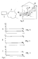
- a transmission system is shown schematically, in which the device 1 for attenuating signals forms a termination of a public network 9, i. H.
- the device 1 for attenuating signals represents a transfer device (also referred to as a "house transfer point") present in a house 10, to which a private internal network 13 is connected.
- the device 1 for attenuating signals is therefore referred to below for the description of the transmission system as a transfer device, for which the same reference number is used.
- Subscriber terminals 11 for example television and radio devices in connection with devices for interactive services
- the z. B. is a broadband network designed for interactive services, a center 8 is connected.
- Fig. 3 only one house 10 is shown with a transfer device 1, but it goes without saying that a plurality of transfer devices 1 are connected to the public network 9.
- the subscriber terminals 11 can send upward signals UP to the control center 8. Since an up signal UP by a transfer device 1 with a fixed damping factor, for. B. 20 dB, is attenuated, the signal level of the up signal UP in the private in-house network 13 is increased by an individually adjustable value. This is done in that each subscriber terminal 11 sends up signals UP with a signal level increased by a certain amount. This amount can be set individually for each house 10, depending on how big the disturbances are.
- the upward signals again have a signal level defined for the public network 9 after the attenuation or are within a level provided for this Range, ie the up signals UP only have a higher signal level where the disturbances mentioned at the beginning can occur, namely in the private in-house network 13.
- the public network 9 no increase in the signal level is necessary, since this is more complex to lay and better maintained than that Private in-house network 13.
- FIG. 3 to show that the disturbances occur in the house 10, a source of interference 12 connected to the private in-house network 13 is shown.
- the interference source 12 is shown here as a source localized at one location, which ideally provides the sum of all interference.
- the transfer device 1 ensures, according to the invention, that interference which is superimposed on an up signal UP in the private in-house network 13 is damped, so that a secure evaluation of the up signal UP is ensured in the control center 8. By contrast, the transfer device 1 does not prevent the interference from being superimposed on an upward signal UP.
- the situation described above is shown in three diagrams, which show average noise and signal levels as (ideal: constant) function of time t.
- the level P is plotted on the ordinate in normalized units from 0 to 4.
- the signal level has the reference symbol SP and the interference level has the reference symbol NP, in each case with an index for reference to the corresponding diagram.
- the levels shown in diagram A correspond to a situation which is present without the application of the invention.
- a "C" is drawn in front of the transfer device 1 in the public network 9 in order to indicate that the upward signal OPEN in Diagram C (Fig. 4) has the signal-to-noise ratio CNR C shown .
- both can be adapted to the local conditions, that is, the filters used can be plugged modules be carried out so that other frequency ranges can be passed and blocked by simply replacing the modules.
- This can e.g. B. become necessary if the frequency distribution of the up and down signals changes due to frequency plan changes or due to modernizations of the public network 9.
- the adjustability of the attenuator 5 shown in FIG. 2 to any attenuation factor has already been pointed out.
- This attenuator 5 can also be designed as a pluggable assembly.
- each high-pass filter 7, low-pass filter 4, 6 and attenuator 5 it is also possible for each high-pass filter 7, low-pass filter 4, 6 and attenuator 5 to have at least one corresponding further element with different properties. With the help of a switch, other filter characteristics and damping factors can be easily defined.
- this attenuation can be adapted, if necessary, to attenuations and amplifications occurring in the public network and in the private in-house network. This enables better and interference-free transmission of signals in multiple access, using types of modulation that are not specially optimized for occurring disturbances.
Applications Claiming Priority (2)
| Application Number | Priority Date | Filing Date | Title |
|---|---|---|---|
| DE19536682A DE19536682A1 (de) | 1995-09-30 | 1995-09-30 | Übertragungssystem mit Übergabeeinrichtungen, die Auswirkungen von Störungen reduzieren |
| DE19536682 | 1995-09-30 |
Publications (2)
| Publication Number | Publication Date |
|---|---|
| EP0766477A2 true EP0766477A2 (fr) | 1997-04-02 |
| EP0766477A3 EP0766477A3 (fr) | 1997-12-17 |
Family
ID=7773824
Family Applications (1)
| Application Number | Title | Priority Date | Filing Date |
|---|---|---|---|
| EP96440074A Ceased EP0766477A3 (fr) | 1995-09-30 | 1996-09-27 | Système de transmission avec dispositifs de tranfert pour réduire les effets d'interférence |
Country Status (3)
| Country | Link |
|---|---|
| US (1) | US6006066A (fr) |
| EP (1) | EP0766477A3 (fr) |
| DE (1) | DE19536682A1 (fr) |
Families Citing this family (6)
| Publication number | Priority date | Publication date | Assignee | Title |
|---|---|---|---|---|
| US6622304B1 (en) * | 1996-09-09 | 2003-09-16 | Thomas W. Carhart | Interface system for computing apparatus and communications stations |
| US6615407B1 (en) * | 1999-02-19 | 2003-09-02 | Masprodenkoh Kabushikikaisha | In-building CATV system, and up-converter and down-converter for use therein |
| JP4066446B2 (ja) * | 1999-05-11 | 2008-03-26 | ソニー株式会社 | 受信装置および方法 |
| US7047555B1 (en) * | 1999-07-23 | 2006-05-16 | Masprodenkoh Kabushikikaisha | In-building CATV system, down-converter, up-converter and amplifier |
| US8132222B2 (en) * | 2007-11-20 | 2012-03-06 | Commscope, Inc. Of North Carolina | Addressable tap units for cable television networks and related methods of remotely controlling bandwidth allocation in such networks |
| US9154180B2 (en) | 2014-03-07 | 2015-10-06 | Thomason Broadband Supply | Signal conditioner for bi-directional radio frequency signals in a telecommunications network |
Citations (4)
| Publication number | Priority date | Publication date | Assignee | Title |
|---|---|---|---|---|
| US3750022A (en) * | 1972-04-26 | 1973-07-31 | Hughes Aircraft Co | System for minimizing upstream noise in a subscriber response cable television system |
| US3924187A (en) * | 1974-05-14 | 1975-12-02 | Magnavox Co | Two-way cable television system with enhanced signal-to-noise ratio for upstream signals |
| JPS6037839A (ja) * | 1983-08-10 | 1985-02-27 | Dx Antenna Co Ltd | 自動利得制御器付双方向増幅器 |
| US5361394A (en) * | 1989-12-19 | 1994-11-01 | Kabushiki Kaisha Toshiba | Upstream signal control apparatus for cable television system |
Family Cites Families (11)
| Publication number | Priority date | Publication date | Assignee | Title |
|---|---|---|---|---|
| US31639A (en) * | 1861-03-05 | Mode of operating reflectors of solar cameras | ||
| US3835393A (en) * | 1972-04-17 | 1974-09-10 | Jerrold Electronics Corp | Duplex cable communications network employing automatic gain control utilizing a band limited noise agc pilot |
| US4633462A (en) * | 1983-07-18 | 1986-12-30 | The Board Of Trustees Of The University Of Illinois | Multiple access communication on a CATV reverse channel |
| DE3404525C1 (de) * | 1984-02-09 | 1985-06-05 | Kurt Wolf & Co Kg, 7547 Wildbad | Anschlußkasten zum Verbinden einer koaxialen Speiseleitung eines Breitbandkabelnetzes mit einer koaxialen Hausanschlußleitung |
| US4633202A (en) * | 1984-12-24 | 1986-12-30 | Rca Corporation | Local area network system with constant tap level |
| US5390337A (en) * | 1992-05-01 | 1995-02-14 | Scientific-Atlanta, Inc. | Combination surge and diplex filter for CATV distribution systems |
| FR2697118B1 (fr) * | 1992-10-19 | 1995-01-06 | Telediffusion Fse | Dispositif de mesure et de réglage des signaux en voie de retour d'un réseau câblé de communication bidirectionnelle, et son utilisation. |
| US5488413A (en) * | 1994-06-14 | 1996-01-30 | Xel Communications, Inc. | CATV telephony system using subsplit band for both directions of transmission |
| US5835844A (en) * | 1995-12-29 | 1998-11-10 | General Instrument Corporation | Bidirectional CATV system having losses for equalizing upstream communication gain |
| US5819159A (en) * | 1996-07-25 | 1998-10-06 | At&T Corp | Method for asymmetrically attenuating signals in a transmission system |
| US5799239A (en) * | 1996-08-26 | 1998-08-25 | At&T Corp | Asymmetric coupling method for attenuating upstream and downstream signals by different amounts to reduce ingress noise |
-
1995
- 1995-09-30 DE DE19536682A patent/DE19536682A1/de not_active Withdrawn
-
1996
- 1996-09-27 EP EP96440074A patent/EP0766477A3/fr not_active Ceased
- 1996-09-30 US US08/724,183 patent/US6006066A/en not_active Expired - Lifetime
Patent Citations (4)
| Publication number | Priority date | Publication date | Assignee | Title |
|---|---|---|---|---|
| US3750022A (en) * | 1972-04-26 | 1973-07-31 | Hughes Aircraft Co | System for minimizing upstream noise in a subscriber response cable television system |
| US3924187A (en) * | 1974-05-14 | 1975-12-02 | Magnavox Co | Two-way cable television system with enhanced signal-to-noise ratio for upstream signals |
| JPS6037839A (ja) * | 1983-08-10 | 1985-02-27 | Dx Antenna Co Ltd | 自動利得制御器付双方向増幅器 |
| US5361394A (en) * | 1989-12-19 | 1994-11-01 | Kabushiki Kaisha Toshiba | Upstream signal control apparatus for cable television system |
Non-Patent Citations (2)
| Title |
|---|
| PATENT ABSTRACTS OF JAPAN vol. 009, no. 159 (E-326), 4.Juli 1985 & JP 60 037839 A (DEIETSUKUSU ANTENA KK), 27.Februar 1985, * |
| UNGER H.G.: 'Hochfrequenztechnik in Funk und Radar', 1972, B.G. TEUBNER, STUTTGART * |
Also Published As
| Publication number | Publication date |
|---|---|
| US6006066A (en) | 1999-12-21 |
| DE19536682A1 (de) | 1997-04-03 |
| EP0766477A3 (fr) | 1997-12-17 |
Similar Documents
| Publication | Publication Date | Title |
|---|---|---|
| DE69532076T2 (de) | Verbesserter, adsl-kompatibler dmt-einrichtung | |
| DE19654173A1 (de) | Vorrichtung und Verfahren zur schnellen Datenübertragung über eine Abzweigleitung eines Nachrichtenübertragungssystems auf Hochspannungsleitungen | |
| DE19505578A1 (de) | Optisches Übertragungssystem für Kabelfernsehsignale und Video- und Telekommunikationssignale | |
| DE60215222T2 (de) | Hybrider faseroptischer und koaxialkabelnetzwerkknoten mit einem kabelmodemabschlusssystem | |
| DE4438942A1 (de) | Optisches Nachrichtenübertragungssystem für Kabelfernsehsignale und für teilnehmerindividuelle Signale | |
| EP0380945A2 (fr) | Système optique de transmission de communications à large bande, en particulier dans la région de branchement d'abonnés | |
| DE19718945C2 (de) | Verfahren und Filter für das Isolieren eines stromaufwärtigen Eindringrauschens in einem bidirektionalen Kabelsystem | |
| EP0795994A2 (fr) | Méthode pour la mise à disposition d'un système de câbles dans la région domestique | |
| DE10061587B4 (de) | Anordnung und Verfahren zur Datenkommunikation in einem Energieverteilungsnetz | |
| EP0766477A2 (fr) | Système de transmission avec dispositifs de tranfert pour réduire les effets d'interférence | |
| DE69814469T2 (de) | Passives kabelfernsehbauelement mit hf-verteiler und anschlussbuchse zur hinzufügung und wegnahme von leistung | |
| DE69630468T2 (de) | Verteilungssystem für breitbandsignale | |
| EP0760584B1 (fr) | Système de transmission électrique avec un réseau de distribution à large bande pour signaux TV et audio et avec une possibilité pour des services interactifs | |
| EP0786176B1 (fr) | Reseau de raccordement d'abonnes hybride a fibres optiques et a cable coaxial | |
| DE4342775C2 (de) | Informationsabrufsystem | |
| DE69730785T2 (de) | Verfahren für die asymmetrische Dämpfung von Signalen in einem Übertragungssystem | |
| DE19701888A1 (de) | System zur optischen Übertragung von Informationen | |
| DE4407831C2 (de) | Verfahren für den Zugriff auf passive Koaxialkabelnetze | |
| EP0701351A2 (fr) | Transmission de signaux numériques en mode paquet sur une fréquence porteuse | |
| DE2648743C2 (de) | Kabelfernsehsystem | |
| EP0905993B1 (fr) | Procédé de transmission sans fil de trains de données dans des réseaux à large bande | |
| DE4405460C1 (de) | Anschlußleitungsnetz | |
| EP0663786B1 (fr) | Procédé de transmission de données numériques | |
| EP0928076B1 (fr) | Système de transmission hybride avec une solution de repliement pour des connections exigeant haute disponibilité | |
| DE4435767A1 (de) | Breitbandinformationssystem für Verteildienste und interaktive Dienste |
Legal Events
| Date | Code | Title | Description |
|---|---|---|---|
| PUAI | Public reference made under article 153(3) epc to a published international application that has entered the european phase |
Free format text: ORIGINAL CODE: 0009012 |
|
| AK | Designated contracting states |
Kind code of ref document: A2 Designated state(s): CH DE ES FR GB IT LI SE |
|
| PUAL | Search report despatched |
Free format text: ORIGINAL CODE: 0009013 |
|
| AK | Designated contracting states |
Kind code of ref document: A3 Designated state(s): CH DE ES FR GB IT LI SE |
|
| 17P | Request for examination filed |
Effective date: 19980401 |
|
| RAP3 | Party data changed (applicant data changed or rights of an application transferred) |
Owner name: ALCATEL |
|
| RAP3 | Party data changed (applicant data changed or rights of an application transferred) |
Owner name: ALCATEL |
|
| 17Q | First examination report despatched |
Effective date: 20010123 |
|
| STAA | Information on the status of an ep patent application or granted ep patent |
Free format text: STATUS: THE APPLICATION HAS BEEN REFUSED |
|
| 18R | Application refused |
Effective date: 20021219 |
|
| P01 | Opt-out of the competence of the unified patent court (upc) registered |
Effective date: 20230520 |