EP0766477A2 - Transmission system with transfer devices which reduce effects of interference - Google Patents
Transmission system with transfer devices which reduce effects of interference Download PDFInfo
- Publication number
- EP0766477A2 EP0766477A2 EP96440074A EP96440074A EP0766477A2 EP 0766477 A2 EP0766477 A2 EP 0766477A2 EP 96440074 A EP96440074 A EP 96440074A EP 96440074 A EP96440074 A EP 96440074A EP 0766477 A2 EP0766477 A2 EP 0766477A2
- Authority
- EP
- European Patent Office
- Prior art keywords
- connection
- signal
- signals
- transmission system
- transfer device
- Prior art date
- Legal status (The legal status is an assumption and is not a legal conclusion. Google has not performed a legal analysis and makes no representation as to the accuracy of the status listed.)
- Ceased
Links
Images
Classifications
-
- H—ELECTRICITY
- H04—ELECTRIC COMMUNICATION TECHNIQUE
- H04N—PICTORIAL COMMUNICATION, e.g. TELEVISION
- H04N7/00—Television systems
- H04N7/16—Analogue secrecy systems; Analogue subscription systems
- H04N7/173—Analogue secrecy systems; Analogue subscription systems with two-way working, e.g. subscriber sending a programme selection signal
- H04N7/17309—Transmission or handling of upstream communications
Definitions
- the invention relates to a transmission system according to the preamble of claim 1.
- the invention also relates to a transfer device for such a transmission system and a device for directionally dependent attenuation of signals.
- the transfer device is the subject of claim 7 and the device for direction-dependent attenuation of signals is the subject of claim 8.
- a transmission system is e.g. B. a broadband distribution network, which is known from H. Hessenmüller et al, "Access Network Structures for Interactive Video Services", Part 1, The Telecommunications Engineer, Volume 48, August 1994.
- BK networks broadband distribution networks, which are also referred to as BK networks.
- BK repeater station In a higher-level BK repeater station, all television and radio programs are combined into a uniform range of programs and distributed to the user-supplied BK repeater stations, which are usually located in local exchanges. From the BK repeater stations, the television and radio programs are distributed downwards to the participants.
- Such a BK network represents a public network that ends at transfer facilities, which are also referred to as house transfer points.
- transfer facilities which are also referred to as house transfer points.
- One or more subscriber terminals can be connected to each transfer device that is usually located in a house via a private internal network.
- SoD Service-on-Demand
- VoD video-on-demand
- back channels are provided in a BK network for signal transmission in the upward direction. This enables subscribers to the SoD exchange to send user data in order to, for. B. Request information.
- the subscriber terminals have additional devices for interactive services, such additional devices are also referred to as set-top boxes.
- a frequency range of approx. 5 - 30 MHz is defined for the return channels (upward signals) and a frequency range of approx. 40 - 300 MHz (450 MHz, hyperband) for the television and radio signals (downward signals).
- the private in-house network is exposed to numerous disruptions, e.g. B. caused by short wave broadcast transmitters, amateur radio equipment and electrical machines.
- some of the cables in the in-house network are designed regardless of such sources of interference.
- the upward signals are particularly disturbed by the interference.
- This problem is known, e.g. B. from N. De Muynck et al, "CATV-cables, they can do more!, International Television Symposium, Montreux, Switzerland, June 15, 1991, pages 179 to 195.
- By a combination of high and low pass filters prevents upward signals with a high signal level from interfering with the downward signals. This is also to prevent the interference superimposed on the uplink signals in the in-house network, ie within the house, from influencing or even interrupting the transmission.
- the invention is based on the object of specifying a transmission system in which upward signals can be received and evaluated by a center, although interference has been superimposed on the upward signals in private in-house networks.
- a transmission system that solves the problem is the subject of claim 1.
- a transfer device for such a transmission system is the subject of claim 7 and a device for directionally dependent attenuation of signals is the subject of claim 8.
- Advantageous embodiments of the invention are specified in the subclaims.
- An advantage of the invention is that the transfer device is a passive device, so that no voltage supply is necessary at the location of the transfer device. It is also advantageous that the transfer device without great effort to local conditions, such. B. can be adjusted to the amount of the local interference level.
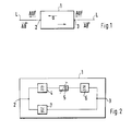
- the device 1 shows a basic circuit diagram of a device 1 for direction-dependent attenuation of signals in order to explain the basic idea of the invention. Following this, the use of such a device 1 for directionally dependent attenuation of signals in a transmission system is explained.
- the device 1 has two connections 2, 3 through which the device 1 can be inserted into a line section L. 3, the line section L is a transmission path, a coaxial cable is preferably used for this.
- a signal can be supplied to connection 2, which is referred to as downward signal AB for the following description.
- a signal can also be fed to the terminal 3, which is referred to below as an upward signal UP.
- the downward signal AB is supplied to the terminal 3 as undamped as possible, and the upward signal UP is supplied to the terminal 2 in an attenuated manner with a fixed damping factor a.
- Fig. 1 the directions of propagation of the up and down signal UP, DOWN are indicated by arrows.
- FIG. 2 shows a block diagram of the device 1 shown in FIG. 1 for direction-dependent attenuation of signals.
- a first branch which is connected at one end to connection 2 and at a second end to connection 3, there are frequency-selective elements, preferably two low-pass filters 4, 6, which are part of a crossover network, and an adjustable attenuator 5 is connected in series.
- two low-pass filters 4, 6, it is possible to insert only a single low-pass filter in the first branch.
- a second branch which is connected in parallel with the first branch and is therefore also connected to the two connections 2, 3, there is a high-pass filter 7 which is part of a crossover network.
- the up signal UP and the down signal AB usually occupy different frequency ranges: the down signal AB (television and radio signals) has frequencies in the range between 40-300 MHz (450 MHz, hyperband) and the up signal UP has frequencies in the range between 5 - 30 MHz.
- the high-pass filter 7 is designed so that the frequency range of the down signal AB is let through almost undamped; the frequency range of the up signal UP is blocked.
- the low-pass filters 4, 6 are designed so that the frequency range of the up signal UP is passed and the frequency range of the down signal AB is blocked. According to the requirements for the filters 4, 5, 7 with regard to the filter characteristics (e.g. cut-off frequencies and filter steepness), filters of an appropriate order are to be selected. The choice and design of appropriate filters are known to a person skilled in the art.
- the device 1 for directional attenuation of signals can be used extensively, for. B. wherever a direction-dependent attenuation of signals is necessary. This can e.g. B. be the case within circuit arrangements or transmission systems. The location at which the device 1 for direction-dependent attenuation of signals is inserted can differ from case to case.
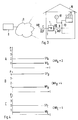
- a transmission system is shown schematically, in which the device 1 for attenuating signals forms a termination of a public network 9, i. H.
- the device 1 for attenuating signals represents a transfer device (also referred to as a "house transfer point") present in a house 10, to which a private internal network 13 is connected.
- the device 1 for attenuating signals is therefore referred to below for the description of the transmission system as a transfer device, for which the same reference number is used.
- Subscriber terminals 11 for example television and radio devices in connection with devices for interactive services
- the z. B. is a broadband network designed for interactive services, a center 8 is connected.
- Fig. 3 only one house 10 is shown with a transfer device 1, but it goes without saying that a plurality of transfer devices 1 are connected to the public network 9.
- the subscriber terminals 11 can send upward signals UP to the control center 8. Since an up signal UP by a transfer device 1 with a fixed damping factor, for. B. 20 dB, is attenuated, the signal level of the up signal UP in the private in-house network 13 is increased by an individually adjustable value. This is done in that each subscriber terminal 11 sends up signals UP with a signal level increased by a certain amount. This amount can be set individually for each house 10, depending on how big the disturbances are.
- the upward signals again have a signal level defined for the public network 9 after the attenuation or are within a level provided for this Range, ie the up signals UP only have a higher signal level where the disturbances mentioned at the beginning can occur, namely in the private in-house network 13.
- the public network 9 no increase in the signal level is necessary, since this is more complex to lay and better maintained than that Private in-house network 13.
- FIG. 3 to show that the disturbances occur in the house 10, a source of interference 12 connected to the private in-house network 13 is shown.
- the interference source 12 is shown here as a source localized at one location, which ideally provides the sum of all interference.
- the transfer device 1 ensures, according to the invention, that interference which is superimposed on an up signal UP in the private in-house network 13 is damped, so that a secure evaluation of the up signal UP is ensured in the control center 8. By contrast, the transfer device 1 does not prevent the interference from being superimposed on an upward signal UP.
- the situation described above is shown in three diagrams, which show average noise and signal levels as (ideal: constant) function of time t.
- the level P is plotted on the ordinate in normalized units from 0 to 4.
- the signal level has the reference symbol SP and the interference level has the reference symbol NP, in each case with an index for reference to the corresponding diagram.
- the levels shown in diagram A correspond to a situation which is present without the application of the invention.
- a "C" is drawn in front of the transfer device 1 in the public network 9 in order to indicate that the upward signal OPEN in Diagram C (Fig. 4) has the signal-to-noise ratio CNR C shown .
- both can be adapted to the local conditions, that is, the filters used can be plugged modules be carried out so that other frequency ranges can be passed and blocked by simply replacing the modules.
- This can e.g. B. become necessary if the frequency distribution of the up and down signals changes due to frequency plan changes or due to modernizations of the public network 9.
- the adjustability of the attenuator 5 shown in FIG. 2 to any attenuation factor has already been pointed out.
- This attenuator 5 can also be designed as a pluggable assembly.
- each high-pass filter 7, low-pass filter 4, 6 and attenuator 5 it is also possible for each high-pass filter 7, low-pass filter 4, 6 and attenuator 5 to have at least one corresponding further element with different properties. With the help of a switch, other filter characteristics and damping factors can be easily defined.
- this attenuation can be adapted, if necessary, to attenuations and amplifications occurring in the public network and in the private in-house network. This enables better and interference-free transmission of signals in multiple access, using types of modulation that are not specially optimized for occurring disturbances.
Abstract
Description
Die Erfindung betrifft ein Übertragungssystem gemäß dem Oberbegriff des Anspruchs 1. Außerdem betrifft die Erfindung eine Übergabeeinrichtung für ein solches Übertragungssystem und eine Einrichtung zum richtungsabhängigen Dämpfen von Signalen. Die Übergabeeinrichtung ist Gegenstand des Anspruchs 7 und die Einrichtung zum richtungsabhängigen Dämpfen von Signalen ist Gegenstand des Anspruchs 8.The invention relates to a transmission system according to the preamble of
Ein Übertragungssystem ist z. B. ein Breitbandverteilnetz, das aus H. Hessenmüller et al, "Zugangsnetzstrukturen für interaktive Videodienste", Teil 1, Der Fernmeldeingenieur, 48. Jahrgang, August 1994, bekannt ist. Darin sind in einer Übersicht Breitbandverteilnetze beschrieben, die auch als BK-Netze bezeichnet werden. In einer übergeordneten BK-Verstärkerstelle werden alle Fernseh- und Rundfunkprogramme zu einem einheitlichen Programmangebot zusammengefaßt und an die benutzerseitigen BK-Verstärkerstellen verteilt, die sich üblicherweise in Ortsvermittlungsstellen befinden. Von den BK-Verstärkerstellen aus, werden die Fernseh- und Rundfunkprogramme in Abwärtsrichtung zu den Teilnehmern verteilt.A transmission system is e.g. B. a broadband distribution network, which is known from H. Hessenmüller et al, "Access Network Structures for Interactive Video Services",
Ein solches BK-Netz stellt ein öffentliches Netz dar, das an Übergabeeinrichtungen endet, die auch als Hausübergabepunkte bezeichnet werden. An jede Übergabeeinrichtung, die sich üblicherweise in einem Haus befindet, können über ein privates hausinternes Netz ein oder mehrere Teilnehmerendgeräte angeschlossen werden.Such a BK network represents a public network that ends at transfer facilities, which are also referred to as house transfer points. One or more subscriber terminals can be connected to each transfer device that is usually located in a house via a private internal network.
Um in einem BK-Netz neben den unidirektionalen Diensten in Abwärtsrichtung (Fernseh- und Rundfunksignale) auch die Möglichkeit für interaktive Dienste, d. h. sogenannte Service-on-Demand (SoD) Dienste wie z. B. Video-on-Demand (VoD), zu schaffen, sind in einem BK-Netz Rückkanäle für eine Signalübertragung in Aufwärtsrichtung vorgesehen. Dadurch können Teilnehmer der SoD-Vermittlungsstelle Nutzdaten senden, um z. B. Information anzufordern. Die Teilnehmerendgeräte haben dafür Zusatzeinrichtungen für interaktive Dienste, solche Zusatzeinrichtungen werden auch als Set-Top Boxen bezeichnet.In order to provide the possibility for interactive services in a BK network in addition to the unidirectional services in the downward direction (television and radio signals). H. So-called Service-on-Demand (SoD) services such as B. video-on-demand (VoD), back channels are provided in a BK network for signal transmission in the upward direction. This enables subscribers to the SoD exchange to send user data in order to, for. B. Request information. The subscriber terminals have additional devices for interactive services, such additional devices are also referred to as set-top boxes.
Bei derzeitigen BK-Netzen ist für die Rückkanäle (Aufwärtssignale) ein Frequenzbereich von ca. 5 - 30 MHz und für die Fernseh- und Rundfunksignale (Abwärtssignale) ein Frequenzbereich von ca. 40 - 300 MHz (450 MHz, Hyperband) festgelegt.In current BK networks, a frequency range of approx. 5 - 30 MHz is defined for the return channels (upward signals) and a frequency range of approx. 40 - 300 MHz (450 MHz, hyperband) for the television and radio signals (downward signals).
Das private hausinterne Netz ist zahlreichen Störungen ausgesetzt, die z. B. von Kurzwellenrundfunksendern, Amateurfunkgeräten und elektrischen Maschinen verursacht werden. Hinzukommt, daß die Kabel des hausinternen Netzes zum Teil ungeachtet solcher Störquellen ausgeführt sind. Durch die Störungen werden besonders die Aufwärtssignale gestört. Diese Problematik ist bekannt, z. B. aus N. De Muynck et al, "CATV-cables, they can do more!", International Television Symposium, Montreux, Schweiz, 15. Juni 1991, Seiten 179 bis 195. Durch eine Kombination von Hoch- und Tiefpaßfiltern wird dort verhindert, daß Aufwärtssignale mit einem hohen Signalpegel die Abwärtssignale stören. Dadurch soll auch verhindert werden, daß die im hausinternen Netz, also innerhalb des Hauses den Aufwärtssignalen überlagerten Störungen die Übertragung beeinflussen oder sogar unterbrechen.The private in-house network is exposed to numerous disruptions, e.g. B. caused by short wave broadcast transmitters, amateur radio equipment and electrical machines. In addition, some of the cables in the in-house network are designed regardless of such sources of interference. The upward signals are particularly disturbed by the interference. This problem is known, e.g. B. from N. De Muynck et al, "CATV-cables, they can do more!", International Television Symposium, Montreux, Switzerland, June 15, 1991, pages 179 to 195. By a combination of high and low pass filters prevents upward signals with a high signal level from interfering with the downward signals. This is also to prevent the interference superimposed on the uplink signals in the in-house network, ie within the house, from influencing or even interrupting the transmission.
Der Erfindung liegt die Aufgabe zugrunde, ein Übertragungssystem anzugeben, bei dem Aufwärtssignale von einer Zentrale empfangen und ausgewertet werden können, obwohl den Aufwärtssignalen in privaten hausinternen Netzen Störungen überlagert wurden. Ein die Aufgabe lösendes Übertragungssystem ist Gegenstand des Anspruchs 1. Eine Übergabeeinrichtung für ein solches Übertragungssystem ist Gegenstand des Anspruchs 7 und eine Einrichtung zum richtungsabhängigen Dämpfen von Signalen ist Gegenstand des Anspruchs 8. Vorteilhafte Ausgestaltungen der Erfindung sind in den Unteransprüchen angegeben.The invention is based on the object of specifying a transmission system in which upward signals can be received and evaluated by a center, although interference has been superimposed on the upward signals in private in-house networks. A transmission system that solves the problem is the subject of
Ein Vorteil der Erfindung ist, daß die Übergabeeinrichtung eine passive Einrichtung ist, so daß am Ort der Übergabeeinrichtung keine Spannungsversorgung notwendig ist. Außerdem ist es von Vorteil, daß die Übergabeeinrichtung ohne großen Aufwand an örtliche Gegebenheiten, z. B. an den Betrag des lokalen Störpegels, angepaßt werden kann.An advantage of the invention is that the transfer device is a passive device, so that no voltage supply is necessary at the location of the transfer device. It is also advantageous that the transfer device without great effort to local conditions, such. B. can be adjusted to the amount of the local interference level.
Die Erfindung wird im folgenden beispielhaft anhand von Zeichnungen erklärt. Es zeigen:
- Fig. 1
- ein Prinzipschaltbild einer Einrichtung zum richtungsabhängigen Dämpfen von Signalen,
- Fig. 2
- ein Blockschaltbild der in Fig. 1 gezeigten Einrichtung zum richtungsabhängigen Dämpfen von Signalen,
- Fig. 3
- ein übertragungssystem mit einer in einem Haus vorhandenen Übergabeeinrichtung, und
- Fig. 4
- drei Diagramme, in denen mittlere Signal- und Störpegel als Funktion der Zeit gezeigt sind.
- Fig. 1
- 2 shows a basic circuit diagram of a device for direction-dependent attenuation of signals,
- Fig. 2
- 1 shows a block diagram of the device for direction-dependent attenuation of signals shown in FIG. 1,
- Fig. 3
- a transmission system with a transfer device present in a house, and
- Fig. 4
- three diagrams showing average signal and noise levels as a function of time.
In Fig. 1 ist ein Prinzipschaltbild einer Einrichtung 1 zum richtungsabhängigen Dämpfen von Signalen gezeigt, um die Grundidee der Erfindung zu erläutern. Im Anschluß daran wird eine Verwendung einer solchen Einrichtung 1 zum richtungsabhängigen Dämpfen von Signalen in einem Übertragungssystem erläutert. Die Einrichtung 1 hat zwei Anschlüsse 2, 3, durch die die Einrichtung 1 in einen Leitungsabschnitt L eingefügt werden kann. Bei einem noch zu erläuternden Übertragungssystem gemäß Fig. 3 ist der Leitungsabschnitt L eine Übertragungsstrecke, vorzugsweise wird dafür ein Koaxialkabel verwendet.1 shows a basic circuit diagram of a
Dem Anschluß 2 kann ein Signal zugeführt werden, das für die folgende Beschreibung als Abwärtssignal AB bezeichnet wird. Auch dem Anschluß 3 kann ein Signal zugeführt werden, das im folgenden als Aufwärtssignal AUF bezeichnet wird. Gemäß der Grundidee der Erfindung wird das Abwärtssignal AB möglichst ungedämpft dem Anschluß 3 zugeführt, und das Aufwärtssignal AUF wird mit einem festgelegten Dämpfungsfaktor a gedämpft dem Anschluß 2 zugeführt. In Fig. 1 sind zur Verdeutlichung die Ausbreitungsrichtungen des Auf- und Abwärtssignals AUF,AB durch Pfeile angedeutet.A signal can be supplied to
In Fig. 2 ist ein Blockschaltbild der in Fig. 1 gezeigten Einrichtung 1 zum richtungsabhängigen Dämpfen von Signalen gezeigt. In einem ersten Zweig, der an einem Ende mit dem Anschluß 2 und an einem zweiten Ende mit dem Anschluß 3 verbunden ist, sind frequenzselektive Elemente, vorzugsweise zwei Tiefpaßfilter 4, 6, die Teil einer Frequenzweiche sind, und ein einstellbares Dämpfungsglied 5 in Serienschaltung vorhanden. Anstatt der beiden Tiefpaßfilter 4, 6 ist es möglich, nur ein einziges Tiefpaßfilter in den ersten Zweig einzufügen. In einem zweiten Zweig, der dem ersten Zweig parallel geschaltet ist und deshalb ebenfalls mit den beiden Anschlüssen 2, 3 verbunden ist, ist ein Hochpaßfilter 7 vorhanden, der Teil einer Frequenzweiche ist.FIG. 2 shows a block diagram of the
In dem bereits erwähnten Übertragungssystem (Fig. 3) belegen das Aufwärtssignal AUF und das Abwärtssignal AB üblicherweise unterschiedliche Frequenzbereiche: Das Abwärtssignal AB (Fernseh- und Rundfunksignale) hat Frequenzen im Bereich zwischen 40 - 300 MHz (450 MHz, Hyperband) und das Aufwärtssignal AUF hat Frequenzen im Bereich zwischen 5 - 30 MHz. Das Hochpaßfilter 7 ist so ausgelegt, daß der Frequenzbereich des Abwärtssignals AB nahezu ungedämpft durchgelassen wird; der Frequenzbereich des Aufwärtssignals AUF wird dagegen gesperrt. Die Tiefpaßfilter 4, 6 sind so ausgelegt, daß der Frequenzbereich des Aufwärtssignals AUF durchgelassen wird und der Frequenzbereich des Abwärtssignals AB gesperrt wird. Entsprechend den Anforderungen an die Filter 4, 5, 7 hinsichtlich der Filtercharakteristiken (z. B. Grenzfrequenzen und Filtersteilheiten), sind Filter entsprechender Ordnung zu wählen. Die Wahl und die Ausführung entsprechender Filter sind einem Fachmann bekannt.In the transmission system already mentioned (FIG. 3), the up signal UP and the down signal AB usually occupy different frequency ranges: the down signal AB (television and radio signals) has frequencies in the range between 40-300 MHz (450 MHz, hyperband) and the up signal UP has frequencies in the range between 5 - 30 MHz. The high-
Die Einrichtung 1 zum richtungsabhängigen Dämpfen von Signalen kann umfangreich verwendet werden, z. B. überall dort, wo eine richtungsabhängige Dämpfung von Signalen notwendig ist. Dies kann z. B. innerhalb von Schaltungsanordnungen oder von Übertragungssystemen der Fall sein. Die Stelle, an der die Einrichtung 1 zum richtungsabhängigen Dämpfen von Signalen eingefügt wird, kann von Fall zu Fall verschieden sein.The
In Fig. 3 ist schematisch ein übertragungssystem gezeigt, bei dem die Einrichtung 1 zum Dämpfen von Signalen einen Abschluß eines öffentlichen Netzes 9 bildet, d. h. die Einrichtung 1 zum Dämpfen von Signalen stellt eine in einem Haus 10 vorhandene Übergabeeinrichtung (auch als "Hausübergabepunkt" bezeichnet) dar, an die ein privates hausinternes Netz 13 angeschlossen ist. Die Einrichtung 1 zum Dämpfen von Signalen wird deshalb im folgenden für die Beschreibung des Übertragungssystems als Übergabeeinrichtung bezeichnet, für die das gleiche Bezugszeichen verwendet wird. An das private hausinterne Netz 13 können Teilnehmerendgeräte 11 (z. B. Fernseh- und Rundfunkgeräte in Verbindung mit Einrichtungen für interaktive Dienste) angeschlossen werden, die die Möglichkeit zum Senden von Aufwärtssignalen besitzen.In Fig. 3 a transmission system is shown schematically, in which the
Mit dem öffentlichen Netz 9, das z. B. ein für interaktive Dienste ausgelegtes Breitbandverteilnetz ist, ist eine Zentrale 8 verbunden. In Fig. 3 ist nur ein Haus 10 mit einer Übergabeeinrichtung 1 eingezeichnet, es ist jedoch selbstverständlich, daß eine Vielzahl von Übergabeeinrichtungen 1 mit dem öffentlichen Netz 9 verbunden sind.With the
Die Teilnehmerendgeräte 11 können Aufwärtswärtssignale AUF zur Zentrale 8 senden. Da ein Aufwärtssignal AUF durch eine Übergabeeinrichtung 1 mit einem festgelegten Dämpfungsfaktor, z. B. 20 dB, gedämpft wird, wird der Signalpegel des Aufwärtssignals AUF im privaten hausinternen Netz 13 um einen individuell einstellbaren Wert erhöht. Dies erfolgt dadurch, daß jedes Teilnehmerendgerät 11 Aufwärtssignale AUF mit einem um einen bestimmten Betrag erhöhten Signalpegel aussendet. Dieser Betrag kann für jedes Haus 10 individuell festgelegt werden, je nach dem wie groß die Störungen sind. Im öffentlichen Netz 9 haben die Aufwärtssignale nach der Dämpfung wieder einen für das öffentliche Netz 9 festgelegten Signalpegel oder liegen innerhalb eines dafür vorgesehenen Bereichs, d. h. die Aufwärtssignale AUF haben nur dort einen höheren Signalpegel, wo die eingangs genannten Störungen auftreten können, nämlich im privaten hausinternen Netz 13. Im öffentlichen Netz 9 ist keine Erhöhung der Signalpegel notwendig, da dieses aufwendiger verlegt und besser gewartet ist, als das private hausinterne Netz 13. In Fig. 3 ist zur Darstellung dessen, daß die Störungen im Haus 10 auftreten eine mit dem privaten hausinternen Netz 13 verbundene Störquelle 12 eingezeichnet. Die Störquelle 12 ist hier als eine an einem Ort lokalisierte Quelle dargestellt, die idealisiert die Summe aller Störungen liefert.The
Durch die Erhöhung des Signalpegels des Aufwärtssignals AUF wird bei unverändertem Pegel der auftretenden Störungen das Signal-Rauschleistungsverhältnis verbessert. Die Übergabeeinrichtung 1 sorgt erfindungsgemäß dafür, daß Störungen, die im privaten hausinternen Netz 13 einem Aufwärtssignal AUF überlagert werden, gedämpft werden, so daß eine gesicherte Auswertung des Aufwärtssignals AUF in der Zentrale 8 gewährleistet ist. Durch die Übergabeeinrichtung 1 wird dagegen nicht verhindert, daß sich die Störungen einem Aufwärtssignal AUF überlagern.By increasing the signal level of the up signal UP, the signal-to-noise ratio is improved while the level of the occurring disturbances remains unchanged. The
In Fig. 4 ist der im vorhergehenden beschriebene Sachverhalt in drei Diagrammen dargestellt, die mittlere Stör- und Signalpegel als (ideal: konstante) Funktion der Zeit t zeigen. An der Ordinate ist der Pegel P in normierten Einheiten von 0 bis 4 aufgetragen. Für die Beschreibung der Diagramme A, B, C hat der Signalpegel das Bezugszeichen SP und der Störpegel das Bezugszeichen NP, jeweils mit einem Index zum Verweis auf das entsprechende Diagramm. Im Diagramm A hat der Störpegel NPA den Pegel 1 und der Signalpegel SPA den Pegel 2, es besteht somit ein Signal-Rauschleistungsverhältnis CNRA = 2. Die im Diagramm A gezeigten Pegel entsprechen einer Situation, wie sie ohne Anwendung der Erfindung vorliegt.4, the situation described above is shown in three diagrams, which show average noise and signal levels as (ideal: constant) function of time t. The level P is plotted on the ordinate in normalized units from 0 to 4. For the description of the diagrams A, B, C, the signal level has the reference symbol SP and the interference level has the reference symbol NP, in each case with an index for reference to the corresponding diagram. In diagram A, the interference level NP A has level 1 and the signal level SP A has level 2, so there is a signal-to-noise ratio CNR A = 2. The levels shown in diagram A correspond to a situation which is present without the application of the invention.
Im Diagramm B ist erfindungsgemäß der Signalpegel SPA um einen Faktor 2 auf einen Pegel 4 erhöht worden, der Störpegel NPB ist unverändert. Hier besteht somit ein Signal-Rauschleistungsverhältnis CNRB = 4, d. h. CNRA < CNRB. In Fig. 3 ist im privaten hausinternen Netz 13 vor der Übergabeeinrichtung ein "B" eingezeichnet, um anzudeuten, daß an dieser Stelle das Aufwärtssignal AUF das in Diagramm C (Fig. 4) dargestellte Signal-Rauschleistungsverhältnis CNRB hat.In diagram B, the signal level SP A has been increased by a factor of 2 to a
Das Diagramm C ergibt sich nach einer Dämpfung der in Diagramm B gezeigten Pegel durch die Übergabeeinrichtung 1 (Fig. 3): Der Signalpegel SPC hat wieder den Pegel 2 und der Störpegel NPC den Pegel 0,5: Das Signal-Rauschleistungsverhältnis CNRC = 2 ist im Vergleich zum Diagramm B unverändert, d. h. CNRB = CNRC = 2. In Fig. 3 ist im öffentlichen Netz 9 vor der Übergabeeinrichtung 1 ein "C" eingezeichnet, um anzudeuten, daß an dieser Stelle das Aufwärtssignal AUF das in Diagramm C (Fig. 4) dargestellte Signal-Rauschleistungsverhältnis CNRC hat.Diagram C is obtained after attenuation of the levels shown in diagram B by transfer device 1 (FIG. 3): signal level SP C is again
Sowohl für die Einrichtung 1 zum richtungsabhängigen Dämpfen von Signalen (Fig. 1 und Fig. 2) als auch für die Übergabeeinrichtung 1 (Fig. 3) gilt, daß beide an die lokalen Gegebenheiten angepaßt werden können, d. h. die verwendeten Filter können als steckbare Baugruppen ausgeführt sein, so daß durch einfaches Austauschen der Baugruppen andere Frequenzbereiche durchgelassen und gesperrt werden können. Dies kann z. B. dann erforderlich werden, wenn sich die Frequenzaufteilung der Auf- und Abwärtssignale aufgrund von Frequenzplanänderungen oder aufgrund von Modernisierungen des öffentlichen Netzes 9 ändert. Auf die Einstellbarkeit des in Fig. 2 gezeigten Dämpfungsglieds 5 auf einen beliebigen Dämpfungsfaktor wurde bereits hingewiesen. Auch dieses Dämpfungsglied 5 kann als steckbare Baugruppe ausgeführt sein.Both for the
Alternativ zu den steckbaren Baugruppen ist es auch möglich, daß zu jedem Hochpaßfilter 7, Tiefpaßfilter 4, 6 und Dämpfungsglied 5 mindestens ein entsprechendes weiteres Element mit unterschiedlichen Eigenschaften vorhanden ist. Mit Hilfe eines Schalters können damit auf einfache Weise andere Filtercharakteristiken und Dämpfungsfaktoren festgelegt werden.As an alternative to the plug-in assemblies, it is also possible for each high-
Durch die Dämpfung des Dämpfungsglieds 5 (Fig. 2) kann gegebenenfalls eine Anpassung dieser Dämpfung an im öffentlichen Netz und im privaten hausinternen Netz vorkommende Dämpfungen und Verstärkungen erfolgen. Dies ermöglicht eine bessere und störsichere Übertragung von Signalen im Mehrfachzugriff, unter Verwendung von Modulationsarten, die nicht speziell für vorkommende Störungen optimiert sind.By damping the attenuator 5 (FIG. 2), this attenuation can be adapted, if necessary, to attenuations and amplifications occurring in the public network and in the private in-house network. This enables better and interference-free transmission of signals in multiple access, using types of modulation that are not specially optimized for occurring disturbances.
Claims (8)
dadurch gekennzeichnet, daß jeweils in einer Übergabeeinrichtung (1) erste Mittel (4, 5, 6) vorhanden sind, die ein dem zweiten Anschluß (3) zugeführtes Aufwärtssignal (AUF) mit einem festgelegten Dämpfungsfaktor (a) dämpfen und dem ersten Anschluß (2) zuführen, und daß das dem zweiten Anschluß (3) zugeführte Aufwärtssignal (AUF) einen Signalpegel hat, der so gewählt ist, daß das Aufwärtssignal (AUF) nach der Dämpfung einen im Verteilnetz (9) festgelegten Pegel hat.Transmission system in which a center (8) is connected to a distribution network (9) which has a plurality of transfer devices (1), each of which is connected to the distribution network (9) by a first connection (2), and in which each transfer device (1) can be connected by a second connection (3) to subscriber terminals (11), which can receive signals (AB) emitted by the control center (8) and which can send up signals (UP) to the control center (8),
characterized in that first means (4, 5, 6) are present in a transfer device (1), which attenuate an upward signal (UP) fed to the second connection (3) with a fixed damping factor (a) and the first connection (2 ) and that the upward signal (UP) fed to the second connection (3) has a signal level which is selected such that the upward signal (UP) has a level defined in the distribution network (9) after attenuation.
dadurch gekennzeichnet, daß die Übergabeeinrichtung (1) erste Mittel (4, 5, 6) hat, die ein dem zweiten Anschluß (3) zugeführtes Aufwärtssignal (AUF) mit einem festgelegten Dämpfungsfaktor (a) dämpfen und dem ersten Anschluß (2) zuführen, und daß das dem zweiten Anschluß (3) zugeführte Aufwärtssignal (AUF) einen Signalpegel hat, der so gewählt ist, daß das Aufwärtssignal (AUF) nach der Dämpfung einen im Verteilnetz (9) festgelegten Pegel hat.Transfer device (1) for a transmission system in which a center (8) is connected to a distribution network (9) and the transfer device (1) is connected to the distribution network (9) by a first connection (2), and in which the Transfer device (1) can be connected by a second connection (3) to subscriber terminal devices (11), which can receive signals (AB) emitted by the control center (8) and which can send up signals (UP) to the control center (8),
characterized in that the transfer device (1) has first means (4, 5, 6) which attenuate an upward signal (UP) fed to the second connection (3) with a fixed damping factor (a) and feed it to the first connection (2), and that the upward signal (UP) fed to the second connection (3) has a signal level which is selected such that the upward signal (UP) has a level defined in the distribution network (9) after attenuation.
Applications Claiming Priority (2)
| Application Number | Priority Date | Filing Date | Title |
|---|---|---|---|
| DE19536682 | 1995-09-30 | ||
| DE19536682A DE19536682A1 (en) | 1995-09-30 | 1995-09-30 | Transmission system with transfer devices that reduce the effects of interference |
Publications (2)
| Publication Number | Publication Date |
|---|---|
| EP0766477A2 true EP0766477A2 (en) | 1997-04-02 |
| EP0766477A3 EP0766477A3 (en) | 1997-12-17 |
Family
ID=7773824
Family Applications (1)
| Application Number | Title | Priority Date | Filing Date |
|---|---|---|---|
| EP96440074A Ceased EP0766477A3 (en) | 1995-09-30 | 1996-09-27 | Transmission system with transfer devices which reduce effects of interference |
Country Status (3)
| Country | Link |
|---|---|
| US (1) | US6006066A (en) |
| EP (1) | EP0766477A3 (en) |
| DE (1) | DE19536682A1 (en) |
Families Citing this family (6)
| Publication number | Priority date | Publication date | Assignee | Title |
|---|---|---|---|---|
| US6622304B1 (en) * | 1996-09-09 | 2003-09-16 | Thomas W. Carhart | Interface system for computing apparatus and communications stations |
| US6615407B1 (en) * | 1999-02-19 | 2003-09-02 | Masprodenkoh Kabushikikaisha | In-building CATV system, and up-converter and down-converter for use therein |
| JP4066446B2 (en) * | 1999-05-11 | 2008-03-26 | ソニー株式会社 | Receiving apparatus and method |
| US7047555B1 (en) * | 1999-07-23 | 2006-05-16 | Masprodenkoh Kabushikikaisha | In-building CATV system, down-converter, up-converter and amplifier |
| US8132222B2 (en) * | 2007-11-20 | 2012-03-06 | Commscope, Inc. Of North Carolina | Addressable tap units for cable television networks and related methods of remotely controlling bandwidth allocation in such networks |
| US9154180B2 (en) | 2014-03-07 | 2015-10-06 | Thomason Broadband Supply | Signal conditioner for bi-directional radio frequency signals in a telecommunications network |
Citations (4)
| Publication number | Priority date | Publication date | Assignee | Title |
|---|---|---|---|---|
| US3750022A (en) * | 1972-04-26 | 1973-07-31 | Hughes Aircraft Co | System for minimizing upstream noise in a subscriber response cable television system |
| US3924187A (en) * | 1974-05-14 | 1975-12-02 | Magnavox Co | Two-way cable television system with enhanced signal-to-noise ratio for upstream signals |
| JPS6037839A (en) * | 1983-08-10 | 1985-02-27 | Dx Antenna Co Ltd | Two-way amplifier with automatic gain controller |
| US5361394A (en) * | 1989-12-19 | 1994-11-01 | Kabushiki Kaisha Toshiba | Upstream signal control apparatus for cable television system |
Family Cites Families (11)
| Publication number | Priority date | Publication date | Assignee | Title |
|---|---|---|---|---|
| US31639A (en) * | 1861-03-05 | Mode of operating reflectors of solar cameras | ||
| US3835393A (en) * | 1972-04-17 | 1974-09-10 | Jerrold Electronics Corp | Duplex cable communications network employing automatic gain control utilizing a band limited noise agc pilot |
| US4633462A (en) * | 1983-07-18 | 1986-12-30 | The Board Of Trustees Of The University Of Illinois | Multiple access communication on a CATV reverse channel |
| DE3404525C1 (en) * | 1984-02-09 | 1985-06-05 | Kurt Wolf & Co Kg, 7547 Wildbad | Connecting box for connecting a coaxial supply line of a broadband cable network to a coaxial domestic connecting line |
| US4633202A (en) * | 1984-12-24 | 1986-12-30 | Rca Corporation | Local area network system with constant tap level |
| US5390337A (en) * | 1992-05-01 | 1995-02-14 | Scientific-Atlanta, Inc. | Combination surge and diplex filter for CATV distribution systems |
| FR2697118B1 (en) * | 1992-10-19 | 1995-01-06 | Telediffusion Fse | Device for measuring and adjusting signals in the return path of a two-way wired communication network, and its use. |
| US5488413A (en) * | 1994-06-14 | 1996-01-30 | Xel Communications, Inc. | CATV telephony system using subsplit band for both directions of transmission |
| US5835844A (en) * | 1995-12-29 | 1998-11-10 | General Instrument Corporation | Bidirectional CATV system having losses for equalizing upstream communication gain |
| US5819159A (en) * | 1996-07-25 | 1998-10-06 | At&T Corp | Method for asymmetrically attenuating signals in a transmission system |
| US5799239A (en) * | 1996-08-26 | 1998-08-25 | At&T Corp | Asymmetric coupling method for attenuating upstream and downstream signals by different amounts to reduce ingress noise |
-
1995
- 1995-09-30 DE DE19536682A patent/DE19536682A1/en not_active Withdrawn
-
1996
- 1996-09-27 EP EP96440074A patent/EP0766477A3/en not_active Ceased
- 1996-09-30 US US08/724,183 patent/US6006066A/en not_active Expired - Lifetime
Patent Citations (4)
| Publication number | Priority date | Publication date | Assignee | Title |
|---|---|---|---|---|
| US3750022A (en) * | 1972-04-26 | 1973-07-31 | Hughes Aircraft Co | System for minimizing upstream noise in a subscriber response cable television system |
| US3924187A (en) * | 1974-05-14 | 1975-12-02 | Magnavox Co | Two-way cable television system with enhanced signal-to-noise ratio for upstream signals |
| JPS6037839A (en) * | 1983-08-10 | 1985-02-27 | Dx Antenna Co Ltd | Two-way amplifier with automatic gain controller |
| US5361394A (en) * | 1989-12-19 | 1994-11-01 | Kabushiki Kaisha Toshiba | Upstream signal control apparatus for cable television system |
Non-Patent Citations (2)
| Title |
|---|
| PATENT ABSTRACTS OF JAPAN vol. 009, no. 159 (E-326), 4.Juli 1985 & JP 60 037839 A (DEIETSUKUSU ANTENA KK), 27.Februar 1985, * |
| UNGER H.G.: 'Hochfrequenztechnik in Funk und Radar', 1972, B.G. TEUBNER, STUTTGART * |
Also Published As
| Publication number | Publication date |
|---|---|
| US6006066A (en) | 1999-12-21 |
| DE19536682A1 (en) | 1997-04-03 |
| EP0766477A3 (en) | 1997-12-17 |
Similar Documents
| Publication | Publication Date | Title |
|---|---|---|
| DE69532076T2 (en) | IMPROVED ADSL COMPATIBLE DMT DEVICE | |
| DE19654173A1 (en) | Device and method for fast data transmission via a branch line of a communication system on high-voltage lines | |
| DE19505578A1 (en) | Optical transmission system for cable television signals and video and telecommunication signals | |
| DE60215222T2 (en) | HYBRID FIBER OPTIC AND COAXIAL CABLE NETWORK NODES WITH A CABLE MODEM CLOSURE SYSTEM | |
| DE4438942A1 (en) | Optical communication system for cable television signals and for subscriber-specific signals | |
| EP0380945A2 (en) | Optical broad-band communication transmission system, especially in the subscriber access area | |
| DE19718945C2 (en) | Method and filter for isolating upstream intrusion noise in a bidirectional cable system | |
| EP0795994A2 (en) | Method for providing a system of cables in the domestic area | |
| DE10061587B4 (en) | Arrangement and method for data communication in a power distribution network | |
| EP0766477A2 (en) | Transmission system with transfer devices which reduce effects of interference | |
| DE69814469T2 (en) | PASSIVE CABLE TELEVISION COMPONENT WITH RF DISTRIBUTOR AND CONNECTING SOCKET FOR ADDING AND TAKING OFF PERFORMANCE | |
| DE69630468T2 (en) | DISTRIBUTION SYSTEM FOR BROADBAND SIGNALS | |
| EP0760584B1 (en) | Electrical transmission system with a wide-band distribution system for TV and audio signals and with a possibility for interactive services | |
| EP0786176B1 (en) | Hybrid optical waveguide and coaxial cable subscriber connection network | |
| DE69730785T2 (en) | Method for the asymmetric attenuation of signals in a transmission system | |
| DE19701888A1 (en) | System for the optical transmission of information | |
| DE4407831C2 (en) | Procedure for accessing passive coaxial cable networks | |
| EP0701351A2 (en) | Carrier frequency transmission of digital signals in burst mode | |
| DE2648743C2 (en) | Cable television system | |
| EP0905993B1 (en) | Method for wireless transmission of data streams in broadband networks | |
| DE4405460C1 (en) | Connection network | |
| EP0663786B1 (en) | Method of digital data transmission | |
| EP0928076B1 (en) | Hybrid transmission system having a fallback solution for connections with high availability requirements | |
| DE4435767A1 (en) | Broadband information system for distribution and interactive services | |
| DE19637070B4 (en) | Additional circuit for multimedia communication |
Legal Events
| Date | Code | Title | Description |
|---|---|---|---|
| PUAI | Public reference made under article 153(3) epc to a published international application that has entered the european phase |
Free format text: ORIGINAL CODE: 0009012 |
|
| AK | Designated contracting states |
Kind code of ref document: A2 Designated state(s): CH DE ES FR GB IT LI SE |
|
| PUAL | Search report despatched |
Free format text: ORIGINAL CODE: 0009013 |
|
| AK | Designated contracting states |
Kind code of ref document: A3 Designated state(s): CH DE ES FR GB IT LI SE |
|
| 17P | Request for examination filed |
Effective date: 19980401 |
|
| RAP3 | Party data changed (applicant data changed or rights of an application transferred) |
Owner name: ALCATEL |
|
| RAP3 | Party data changed (applicant data changed or rights of an application transferred) |
Owner name: ALCATEL |
|
| 17Q | First examination report despatched |
Effective date: 20010123 |
|
| STAA | Information on the status of an ep patent application or granted ep patent |
Free format text: STATUS: THE APPLICATION HAS BEEN REFUSED |
|
| 18R | Application refused |
Effective date: 20021219 |
|
| P01 | Opt-out of the competence of the unified patent court (upc) registered |
Effective date: 20230520 |