EP0124331B1 - Dispositif émetteur de télécommande d'un ou plusieurs appareils de télévision - Google Patents
Dispositif émetteur de télécommande d'un ou plusieurs appareils de télévision Download PDFInfo
- Publication number
- EP0124331B1 EP0124331B1 EP84302714A EP84302714A EP0124331B1 EP 0124331 B1 EP0124331 B1 EP 0124331B1 EP 84302714 A EP84302714 A EP 84302714A EP 84302714 A EP84302714 A EP 84302714A EP 0124331 B1 EP0124331 B1 EP 0124331B1
- Authority
- EP
- European Patent Office
- Prior art keywords
- remote control
- transmitter
- input
- data
- type
- Prior art date
- Legal status (The legal status is an assumption and is not a legal conclusion. Google has not performed a legal analysis and makes no representation as to the accuracy of the status listed.)
- Expired - Lifetime
Links
Images


Classifications
-
- H—ELECTRICITY
- H04—ELECTRIC COMMUNICATION TECHNIQUE
- H04B—TRANSMISSION
- H04B1/00—Details of transmission systems, not covered by a single one of groups H04B3/00 - H04B13/00; Details of transmission systems not characterised by the medium used for transmission
- H04B1/06—Receivers
- H04B1/16—Circuits
- H04B1/20—Circuits for coupling gramophone pick-up, recorder output, or microphone to receiver
- H04B1/202—Circuits for coupling gramophone pick-up, recorder output, or microphone to receiver by remote control
Definitions
- the present invention concerns an arrangement which can be used in the manufacture of individual remote control transmitters for controlling a television receiver, a video tape recorder or a video disc player, or in a single, unified remote control transmitter for controlling the devices.
- EP-A-0002434 discloses a computer-controlled remote control transmitter with which many different functions can be controlled remotely, the range of functions possibly covering more than one remote device, while the transmitter has a simple keypad.
- the function to be controlled may be determined by a control key inserted into the transmitter. It is not clear how the transmitter computer is enabled to generate signals appropriate to whichever function is selected.
- the control key is a magnetically readable data carrier, on which a fixed program, operands and the like are stored. It appears from this that maybe the computer is programmed appropriately for the function the transmitter is to control, by reading the program from the data carrier which, on insertion into the transmitter, specifies that function.
- EP-A-0122548 which was published after the filing date of the present application but which has an earlier priority date than the priority date of the present application, discloses a remote control transmitter which can be trained to transmit the signal codes appropriate to one particular model or brand of a device type out of a plurality of possible models or brands.
- the transmitter is for controlling a VCR, it has pre-stored in it the signal codes appropriate for operation of various models and manufacturers' brands of VCRs.
- the learning mode it learns unambiguously which particular model or brand of VCR it is to control, and then later transmits only the codes appropriate for the single unambiguously learnt model or brand of VCR.
- a television receiver (TV) 10 receives television signals from video cassette recorder player (VCR) 12 and video disc player (VD) 14 for reproduction.
- VCR video cassette recorder player
- VD video disc player
- An RF source 16 (which may be an antenna, as shown, or a cable distribution network) provides RF signals to VCR 12.
- TV 10 and VCR 12 include respective tuners.
- a switching arrangement is included within VCR 12 for selectively coupling the signals to only the tuner of TV 10 or to both the tuner of TV 10 and the tuner of VCR 12. In the latter state, one channel can be reproduced by TV 10 while another is being recorded by VCR 12.
- Individual remote control transmitters 10a, 12a and 14a are provided for controlling various functions of TV 10, VCR 12 and VD 14.
- the remote control messages generated by individual remote control transmitters 10a, 12a and 14a are provided for controlling various functions of TV 10, VCR 12 and VD 14.
- the remote control messages generated by individual remote control transmitters 10a, 12a and 14a are received and processed by remote control receiver (RCRCVR) sections 10b, 12b and 14b of TV 10, CVR 12 and VD 14, respectively, to control the devices in accordance with the remote control messages.
- RCRCVR remote control receiver
- the remote control messages are generated when a user depresses respective keys of a remote control transmitter.
- the following tables indicate the functions of TV 10, VCR 12 and VD 14 which are controlled when respective keys of transmitters 10a, 12a and 14a are depressed.
- a unified remote control transmitter 20 for controlling TV 10, VCR 12 and VD 14 shown in Figure 1, is shown in Figure 2. Since many of the keys are used to control more than one device, unified remote control transmitter 20 includes device selection keys TV, VCR and VD for determining which one of TV 10, VCR 12 or VD 24 is to be controlled.
- the following table indicates the function or functions of the keys of unified remote control transmitter 20. As is indicated, some functions depend on which device key has been previously depressed while others unconditionally control a particular device independent of which device key has been previously depressed. Still other functions depend on which device and function keys have been previously depressed. It will also be noted that there is no ON key. This is so because the selection of a device key will automatically cause the respective device to be turned on.
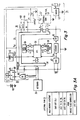
- FIG 3 is a schematic of a remote control arrangement which can be used in any of the individual remote control transmitters shown in Figure 1 or in the unified remote control transmitter shown in Figure 2.
- a remote control arrangement which can be used in any of the individual remote control transmitters shown in Figure 1 or in the unified remote control transmitter shown in Figure 2.
- Microcontroller 32 operates under the control of a stored program which is always the same, i.e., is independent of the type of remote control transmitter.
- Driver section 34 is also always the same. Accordingly, a significant part of all the remote control transmitters is the same. This reduces the parts inventory and testing required to manufacture the four different types of remote control transmitters and consequently the cost to both the manufacturer and consumer.
- Keyboard 30 is selected in accordance with the type of remote control transmitter. However, the key codes for keys common to both an individual remote control transmitter and the unified remote control transmitter are the same.
- certain input and output terminals of microcontroller 32 are selectively connected, i.e., "strapped", by the manufacturer either to each other, to the supply voltage (VDD) conductor, or to the reference voltage (ground) conductor in a strap configuration 36.
- Strap configuration 36 is examined, i.e., "read", by microcontroller 32 to determine the action to be taken in response to the activation of the keys.
- the remote control messages include a preamble portion which identifies the device to be controlled and a data portion which identifies the function to be controlled. If the transmitter is an individual one (10a, 12a or 14a in Figure 1), strap configuration 36 determines the preamble portion of the remote control message.
- strap configuration 36 determines the preamble, and possibly the data portion, in accordance with the contents of an external memory 38.
- External memory 37 also stores information, such as the skip list referred to above.
- the switches of the various keys of keyboard 30 are coupled to a power supply switching circuit 38, in addition to microcontroller 32.
- power supply switching circuit 38 is caused to couple a supply voltage from a battery 40 to the rest of the remote control transmitter, including microcontroller 32.
- Microcontroller 32 responds to the depressed key by generating a digital word representing the appropriate remote control message.
- a carrier signal is modulated in accordance with the remote control message representative word within microcontroller 32, in the manner to be described below, and coupled to a driver-amplifier 42 of driver section 34.
- the modulated carrier is amplified by a driver-amplifier 48 and applied to a transducer 44.
- Transducer 50 which may comprise an infrared light emitting diode, transmits the modulated carrier.
- Power supply switching circuit 38 includes an "OR" function gate 46, a set-reset flip-flop (S-R FF) 48 and an electronic switch 50.
- S-R FF 48 When any one of the keys of keyboard 10 is depressed, S-R FF 48 is “set” whereby a high logic level (or logic “1") is developed at its Q output.
- Normally non-conductive electronic switch 50 is rendered conductive in response to logic "1" produced at the Q output of S-R FF 48.
- the supply voltage provided by a battery 40 is coupled to a supply voltage input (labeled V c c) of microcontroller 32 and to respective supply voltage inputs of driver-amplifier 42.
- microprocessor 12 After microprocessor 12 has caused the remote control message corresponding to a depressed key to be transmitted, it generates a "power off” signal (a logic “1") which causes S-R FF 48 to be “reset” whereby a logic "0" is developed at its Q output. In response, switch 50 is rendered “non-conductive” and the supply voltage from battery 40 is decoupled from microcontroller 32 and driver-amplifier 42. Thus, the transmitter is only energized long enough for the remote control command to be transmitted after a key is depressed. This increases the lifetime of battery 40.
- switch 50 is also coupled to a "power up” detector 52 which in turn has an output coupled to a "reset” input of microcontroller 32.
- power up detector 30 When a key of keyboard 30 is depressed and switch 50 is, as a result, rendered conductive to couple supply voltage to microprocessor 32, power up detector 30 generates a "reset" pulse. In response to the reset pulse, the control program for micro controller 32 is initiated as will be described below.
- Microcontroller 32 includes input and output (I/O) ports 54 by which data (in digital form) is received from and coupled to external devices.
- a central processing unit (CPU) 56 controls the transfer and processing of data under the control of a program stored in a read-only memory (ROM) 58.
- ROM read-only memory
- CPU 56 addresses ROM 58, reads the instruction stored at the addressed memory location and processes or transfers data according to the instruction.
- memory locations of an internal volatile random access memory (RAM) 60 are used to temporarily store data as it is processed.
- CPU 54 addresses RAM 40 and transfers data to and from the addressed memory location of RAM 40.
- Timing signals for microcontroller 32 are derived from the output signal of a crystal oscillator 62.
- the frequency of oscillator 62 is also divided by counter 64 to derive the carrier signal.
- the carrier signal is coupled to an electronic switch 66 the conduction of which controlled by the bits (binary digits) of the remote control message representative word to derive the modulated carrier which is coupled to driver-amplifier 42.
- External RAM 37 is included in the individual remote control transmitters (10a and 12b of Figure 1) for the television receiver and the video cassette recorder and in the unified remote control transmitter (20 of Figure 2) but not in the individual remote control transmitter (14a of Figure 1) for the video disc player and is therefore indicated with phantom lines.
- External RAM 37 is used to store a list of preferred and non-preferred channels, i.e., a "skip list", the last device selected for control in the case of the unified remote control transmitter, and other data as well as other data indicated in Figure 3A. This will be discussed in greater detail with respect to the flow chart of the control program stored shown in Figures 5A-B and 6A-E.
- CPU 56 addresses RAM 37 and transfers data to and from the addressed memory location.
- Battery 40 is directly connected to the supply voltage input (Vee) of RAM 37 rather than through switch 50 so that the contents of RAM 37 are maintained when the remote control transmitter is off, i.e., when none of its keys are depressed.
- the COP 420L microprocessor available from National Semiconductor Corp., Santa Clara, California, is a suitable choice for microcontroller 32 and the COP 499 RAM, also available from National Semiconductor Corp., is a suitable choice for RAM 37.
- the COP 420L microprocessor is constructed with CMOS (complementary metal-oxide semiconductor) devices and therefore is particularly well suited since CMOS devices use relatively small amounts of energy.
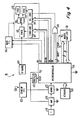
- FIG. 1 A schematic of remote control receiver section 10b of TV 10 shown in Figure 1 is shown in Figure 4. While remote control sections of VCR 12 and 14b of VD 14 are generally similar, the television remote control section has been illustrated so that the function of certain complex remote control messages discussed with respect to Figures 5A-C and 6A-D will be better understood.
- television receiver 10 includes a signal processing section 102 including a voltage controlled tuner 102 for converting the RF signal for a selected channel received from an RF source 104 (such as antenna 16 or VCR 14 shown in Figure 1) to a corresponding IF signal.
- the IF signal is demodulated by a demodulator 106 to produce video and audio signals which are processed in respective sections 108 and 110.
- a tuner control unit 110 generates a tuning control voltage for tuner 102 in accordance with the channel number the selected channel stored, in digital form, in an internal register.
- a volume control unit 112 generates a volume control voltage for controlling the audio volume level in accordance with a volume level representative digital word stored in an internal register. The volume may be "muted” in response to a "mute” command signal.
- a main power supply 116 selectively provides operating voltages to signal processing section 100 in response to "on" and "off" command signals.
- Remote control receiver section 10b includes a transducer 118 from converting received remote control messages to a corresponding electrical signal and an amplifier 120 for amplifying these signals.
- a demodulator which may simply comprise an envelop detector, produces a digital word representing in serial form the remote control message in response to the electrical signal provided by amplifier 120.
- the remote control message is examined by a microcontroller to generate the "on", "off” and “mute” command signals and the channel number and volume representative digital words.
- microcontroller 124 examines the preamble of the remote control message to determine if it is correct and if it is thereafter decodes the data portion of the remote control message to produce the various command and control level representative digital word signals.
- a standby power supply 126 continually provides supply voltages to the various portions of remote control receiver section 102 so that remote control receiver 10b is always in a condition to receive remote control messages and so that the on, off and mute commands and the channel number and volume level representative digital words are maintained when signal processing section 100 is "off".
- the remote control message when a television channel is selected by means of the CU and CD keys, the remote control message has a complex form including both the channel number and either the channel up or channel down command (depending on whether the CU or the CD key was depressed). The purpose of this is to enable the audio to be muted while a channel is being changed.
- the complex remote control message is decoded by microcontroller 124 of TV remote control section 10b to derive the channel number and the appropriate one of a CU or CD signal.
- the CU or CD signal is coupled through an OR function circuit 126 (the function of which may be performed by microcontroller 124) to the mute control input of volume control unit 114.
- microcontroller 124 When a television channel is selected by means of the digit keys, the digits of the channel number are transmitted one at a time and the complete channel number is formed by microcontroller 124 when both digits have been received. At that time microcontroller 112 itself generates a mute signal which is coupled through OR function gate 126 to volume control unit 114. The mute signal generated when the MUTE key of the remote control transmitter is depressed is also coupled to the mute control input of volume control unit 114 through OR function circuit 126. The latter allows audio to be muted at anytime as desired.
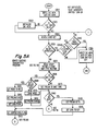
- the control program is initiated when a key is depressed and a reset signal is applied to the reset input of microcontroller 32.
- the contents of the memory location of external RAM 37 are read into corresponding memory locations of internal RAM 60 (001).
- the contents of a particular memory location (identified as VALID MEMORY in Figure 3A) in which a predetermined validity constant should have been stored, if the supply voltage to external RAM 37 was not disturbed, are examined to determine if the contents of external RAM 37 have been maintained (002). If the contents of external RAM 37 have not been maintained, certain initialization data is loaded into the memory locations of internal RAM 60 corresponding to those of external RAM 37 (003) as follows:
- external RAM 37 The contents of external RAM 37 are read into internal RAM 60 at the beginning of the program to increase the speed at which data can be processed since it takes considerably more time to read and write data from and into external RAM 37 than from and into internal RAM 60.
- strap configuration 36 is examined to identify the type of remote control transmitter (007). This portion of the program is shown in detail in Figure 6A.
- the remote control transmitter is a unified one (008)
- an examination is made to determine if the key that was depressed is a device key, i.e., a TV, VCR or VD key (009). If key was a device key, the mode is set to the corresponding device and stored in its corresponding memory location (010), the preamble portion of the remote control message is also set to the corresponding device (011) and the data portion ofthe remote control message is set to the "on" function (012). Then, after clearing a flag register (013) the contents of which are used to indicate whether or not a complex remote control message is to be transmitted as described below, the remote control message is caused to be transmitted (starting at point B) in the portion of the program shown in detail in Figure 6B. This causes the device selected to be turned on. Thereafter, the program returns to point A to wait for the next key to be depressed.
- a device key i.e., a TV, VCR or VD key (009). If key was a device key, the
- the mode of operation is determined by the last device key which was depressed which is stored in the mode memory location. Accordingly, the contents of the mode memory location (014) are read and the preamble is set in accordance with the contents (015). Thereafter an examination is begun (at 016) to determine which function key was depressed in order to generate the data portion of the remote control message.
- the preamble is set in accordance with the type of the transmitter, i.e., TV, VCR or VD (017) as identified by strap configuration 36 and an examination is begun (starting at 016) to determine which function key was depressed to generate the data portion of the remote control message.
- the type of the transmitter i.e., TV, VCR or VD (017) as identified by strap configuration 36 and an examination is begun (starting at 016) to determine which function key was depressed to generate the data portion of the remote control message.
- the determination of which function key was depressed begins with a determination of whether the function key was the mute key (016). If it was the mute key, the preamble is set to TV (018) and the data is set in accordance to the depressed key (019), i.e., mute. After the complex message flag is cleared (013) the remote control message is transmitted (starting at point B). Thus, when the mute key is depressed the audio output of the television receiver is unconditionally muted.
- the mode and transmitter type are examined to determine if either corresponds to VCR (021). If not, the preamble is set to TV (022) and the data is set in accordance with the depressed key, i.e., VU or VD (023). After the complex message flag is cleared (024) the remote control message is transmitted (starting at point B).
- the depressed key was VU or VD (020) and the mode or type is VCR (021) the last key (before the present one) is examined (025). If it was the SM (slow motion) key, the preamble is set to VCR (026) and the data is set to TU (track up) or TD (track down) depending on whether the VU or VD was depressed (027). After the complex message flag is cleared (024) the remote message control message is transmitted (starting at point B).
- a direct entry portion of the program (029) shown in detail in Figure 6C is executed (029) to form the two digit channel number of the desired channel and the data is set in accordance with the depressed key, i.e., the particular digit key.
- the complex message flag is cleared (024)
- a remote control message with the preamble set to either TV or VCR (in accordance with step 015 or 017) and with the data set to the particular digit of the channel number corresponding to the. depressed key is transmitted (starting at point B).
- the next channel in the skip list is located by executing a channel scanning portion of the program (031) shown in detail in Figure 6D. Thereafter a remote control message with the preamble set to either TV or VCR and the data set to the channel number of next channel in the skip list is transmitted (starting at point B).
- the remote control message will be a complex message including either CU or CD (depending on whether CU or CD was depressed). As earlier noted, if the selected device was the television receiver, this causes the audio to be muted while the new channel is being tuned.
- the last channel selected is added or removed from the skip list by executing a channel skip list set up portion of the program (033) shown in detail in Figure 6E. Thereafter, the remote control message with the preamble set to either TV or VCR and the data set to the channel number of the last channel selected is transmitted. In response to this remote control message generated, the last channel is again tuned. If the last device selected was the television receiver, the image will temporarily disappear and then reappear as the last channel is returned. This indicates to a user that the desired action (i.e., either the addition of removal of the selected channel from the skip list) has taken place.
- the desired action i.e., either the addition of removal of the selected channel from the skip list
- the remote message When a channel is added or deleted, the remote message is complex and it includes, in addition to the channel number, the command "add” or "erase". This is desirable since it allows a skip memory included in television receiver or video cassette recorder to be set up when the skip list in the remote control transmitter is set up.
- the inclusion of a skip memory in the television receiver or video cassette recorder allows channels to be selected at the device itself in the same manner as with the remote control transmitter.
- a keyboard 128 for entering channel selection commands, as well as other function commands such as “on”, “off”, “volume up” and “volume down” and a memory 130 for storing the skip list are coupled to microcontroller 124. Since supply voltage is always provided by standby power supply 126, memory 130 may be included within microcontroller 124 if desired.
- the data is set in accordance with the depressed key (023), the complex message flag is cleared (024) and the remote control message is transmitted (starting at point B).
- an input terminal (IN) can be connected either to the supply voltage (V cc ) conductor (a logic "1"), the reference voltage (ground) conductor (a logic "0"), to first output terminal (OUT 1) or to a second output terminal (OUT 2).
- V cc supply voltage
- ground ground
- OUT 1 first output terminal
- OUT 2 second output terminal
- the number of remote control types that can be defined by such a strap configuration where an input terminal is tied to either the supply voltage conductor, the reference voltage conductor or to an output terminal is:
- output terminals OUT 1 and OUT 2 are sequentially set to different logic states and the state of input terminal IN is examined at each logic state.
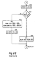
- the flow chart for the portion of program for forming and transmitting the remote control message is shown in Figure 6B.
- the key that was depressed is stored in a memory location of internal RAM 60 identified as LAST KEY (034).
- LAST KEY (034)
- the contents of a complex message flag register are examined (035) to determine the type of remote control message to be transmitted.
- the contents of the LAST KEY memory location are transferred to a corresponding memory location of external RAM 37 before the program ends (see 006 of Figure 5A) for future reference in determining the preamble and data of a remote control message (see 025 of Figure 5B).
- the remote control message has the form: where the "bars" indicate that each bit of the corresponding digital word is complemented.
- Such type remote control message in which the preamble and data are repeated in complemented form is conventionally used in remote control systems to reduce the possibility of error.
- the remote control message has the form:
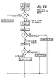
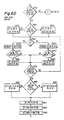
- the flow chart portion for transmitting the tens and units digits of a channel number when a channel is directly selected is shown in Figure 6C. If the transmitter type or mode (device to be controlled) is TV or VCR (039), if a digit key has been depressed, "z entry" flag register is examined (040). If the entry flag is not set, indicating that the depressed digit key corresponds to the tens digit, the digit key is stored in a memory location for the tens digit of the channel number (041). The entry flag is then set (042) and a timer comprising an internal counter, is started (043).
- the digit corresponding to the depressed key is transmitted as the data portion (see 023 of Figure 5B) of a remote control message having a preamble set to either TV or VCR in accordance with the device selected for control in the case of a unified transmitter (see 015 of Figure 5A) or the transmitter type (see 017 of Figure 5A).
- the entry flag will have been previously set (040) to indicate that the second depressed digit key corresponds to the tens digit of the channel number of the desired channel.
- the digit corresponding to the depressed digit key is stored in a memory location for the units digit of the channel number (045), the entry flag is cleared (046) and the timer is cleared (047).
- the channel number is stored in the memory location for the last TV channel if the transmitter type or more (device to be controlled) is TV (048 and 049) or in the memory location for the last VCR channel if the transmitter type or mode is VCR (049 and 050).
- the units digit is transmitted in the same manner as the tens digit of the channel number.
- the channel number for the last TV channel selected is used as the starting point for the channel scanning operation to locate next TV channel and the channel number for the last VCR channel selected is used as the starting point for the channel scanning operation to locate the next VCR channel.
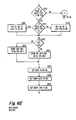
- the transmitter type or mode (device to be controlled) is TV or VCR (051 )
- the transmitter type or mode is TV or VCR (051 )
- the channel number is set to the last TV channel number (053).
- the transmitter type or mode is VCR, the channel number is set to the last VCR channel number (054).
- the channel number is increased by one (056U). If the highest channel number has been exceeded (057U), the channel number is set to the lowest channel number (058U) to continue the scanning operation within the range of legitimate channel numbers. Thereafter, the memory location of the skip list for the present channel number, indicated in the flow chart by SL (CH.NO.), is examined to determine if it contains a "skip" indication, e.g., a logic "0" (059). If the memory location of the skip list for the present channel number contains a skip indication, the channel number is again increased until a "no skip” indication, e.g., a logic "1", is found. Essentially, the same operation occurs if the CD key was depressed, except, of course, that the channel number is decreased (see 055, 056D, 057D, 058D and 059).
- the corresponding channel number is stored in the memory location for the last TV channel if the transmitter type or mode is TV (060 and 061) or stored in the memory location for the last VCR channel if the transmitter type or mode is VCR (060 and 062). Then, the data is set to the channel number (063), the complex data is set to the depressed key, i.e., either CU or CD (064) and the complex message flag is set (065). Thereafter, the complex remote control message is transmitted with the appropriate preamble, i.e., either TV or VCR.
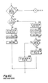
- the flow chart for the add and erase portion of the program is shown in Figure 6E. If the transmitter type or mode is TV or VCR (066) if one of the ADD or ERASE keys has been depressed, the channel number is set to the last TV channel if the transmitter type or mode is TV (067 and 068) or set to the last VCR channel of the transmitter type or mode is VCR (067 and 069). If the ADD key was depressed (070), a "no skip" indication is stored in the memory location of the skip list for the present channel number (071). If the ERASE key was depressed (070), a "skip” indication is stored in the memory location of the skip list for the present channel (072). Then, the data is set to the present channel number (073), the complex data is set to the depressed key, i.e., either ADD or ERASE, (074) the complex message flag is set (075). Thereafter, the complex remote control message is transmitted.
- FIG. 7 The flow chart for the program for processing received remote control messages in the remote control receiver portion of the television receiver shown in Figure 4 is shown in Figures 7 and 8.
- the program is started when supply voltage is initially provided from standby power supply 126 and a reset signal is generated by a power up detector 132 and applied to the reset input of microcontroller 124.
- the input terminals of microcontroller 124 coupled to keyboard 128 are monitored to determine if a keyboard entry has been made (076) and if this is the case, executes the appropriate function (077).
- the input terminal of microcontroller 124 coupled to the output of demodulator 122 is monitored to determine if a remote control message has been received (078).
- a remote control message If a remote control message has been received, it is decoded (079) to determine the preamble, data and complex data, if any. The validity of the remote control message is determined by comparing the complemented and uncomplemented portions (080). The preamble is examined to determine if it corresponds to the device being controlled (081). If the message is not valid (080) or the preamble is incorrect (081) the program returns (to point A) to wait for the next keyboard entry or remote control message.
- the channel number is formed similar to that in which the channel number is formed in the remote control transmitter (085-095).
- a mute signal is generated for a predetermined time long enough for the new channel to be tuned (093) and the channel number is applied to tuner control unit 112 in order to cause the corresponding channel to be tuned (094).
- the portion of the program for executing complex remote control messages is shown in Figure 8. Since the data portion of a complex remote control message represents a channel number, the channel number is set to the data (097).
- a mute signal is generated for the predetermined time (099) and thereafter the channel corresponding to the channel number is caused to be tuned (100).
- the respective "skip” or “no skip” indication is stored in the memory location for the channel number (101-103). Thereafter the channel corresponding to the channel number is caused to be tuned (100).
- the program for processing remote control messages for the video cassette recorder and video disc player are similar to that for the television receiver except in the case of the video cassette recorder the mute signal need not be generated and in the case of the video disc both the mute signal and the channel tuning commands need not be generated.
- the same program may be used for all the devices.
- the preambles serve to route the program to portions for executing commands with which the particular device is concerned.
Claims (8)
caractérisé en ce que
Applications Claiming Priority (2)
| Application Number | Priority Date | Filing Date | Title |
|---|---|---|---|
| US490721 | 1983-05-02 | ||
| US06/490,721 US4566034A (en) | 1983-05-02 | 1983-05-02 | Remote control transmitter arrangement for one or more television devices |
Publications (4)
| Publication Number | Publication Date |
|---|---|
| EP0124331A2 EP0124331A2 (fr) | 1984-11-07 |
| EP0124331A3 EP0124331A3 (en) | 1986-02-05 |
| EP0124331B1 true EP0124331B1 (fr) | 1990-02-21 |
| EP0124331B2 EP0124331B2 (fr) | 1999-03-03 |
Family
ID=23949192
Family Applications (1)
| Application Number | Title | Priority Date | Filing Date |
|---|---|---|---|
| EP84302714A Expired - Lifetime EP0124331B2 (fr) | 1983-05-02 | 1984-04-19 | Dispositif émetteur de télécommande d'un ou plusieurs appareils de télévision |
Country Status (6)
| Country | Link |
|---|---|
| US (1) | US4566034A (fr) |
| EP (1) | EP0124331B2 (fr) |
| JP (1) | JPS59219096A (fr) |
| CA (1) | CA1214860A (fr) |
| DE (1) | DE3481397D1 (fr) |
| HK (1) | HK17895A (fr) |
Families Citing this family (127)
| Publication number | Priority date | Publication date | Assignee | Title |
|---|---|---|---|---|
| US4965825A (en) | 1981-11-03 | 1990-10-23 | The Personalized Mass Media Corporation | Signal processing apparatus and methods |
| USRE47642E1 (en) | 1981-11-03 | 2019-10-08 | Personalized Media Communications LLC | Signal processing apparatus and methods |
| US7831204B1 (en) | 1981-11-03 | 2010-11-09 | Personalized Media Communications, Llc | Signal processing apparatus and methods |
| US5692214A (en) * | 1981-12-14 | 1997-11-25 | Levine; Michael R. | System for unattended recording of video programs by remote control code transmitter module which receives user selections from a personal computer |
| JPS6184989A (ja) * | 1984-10-02 | 1986-04-30 | Sony Corp | タイマ−装置 |
| US6256034B1 (en) | 1986-06-27 | 2001-07-03 | Sture Olsson | Device for marking edges of shelves |
| US5019811A (en) * | 1984-10-15 | 1991-05-28 | Unigrafic Ag | Device for marking edges of shelves |
| FR2575573B1 (fr) * | 1984-12-28 | 1987-02-06 | Radiotechnique | Dispositif recepteur de telecommande utilisant une onde porteuse modulee |
| US4751578A (en) * | 1985-05-28 | 1988-06-14 | David P. Gordon | System for electronically controllably viewing on a television updateable television programming information |
| US4703359A (en) * | 1985-05-30 | 1987-10-27 | Nap Consumer Electronics Corp. | Universal remote control unit with model identification capability |
| US4774511A (en) * | 1985-05-30 | 1988-09-27 | Nap Consumer Electronics Corp. | Universal remote control unit |
| US5872562A (en) * | 1985-05-30 | 1999-02-16 | U.S. Philips Corporation | Universal remote control transmitter with simplified device identification |
| US4746919A (en) * | 1986-03-28 | 1988-05-24 | Rca Licensing Corporation | Remote control system with key function display provisions |
| JP2580137B2 (ja) | 1986-11-12 | 1997-02-12 | ソニー株式会社 | リモ−トコマンダ− |
| US4962466A (en) * | 1987-03-27 | 1990-10-09 | Viscom Systems, Inc. | Electronic product information display system |
| US4888709A (en) * | 1987-03-27 | 1989-12-19 | Viscom Systems, Inc. | Electronic product information display system |
| US6014092A (en) | 1987-10-14 | 2000-01-11 | Universal Electronics Inc. | Key mover |
| US4959810A (en) * | 1987-10-14 | 1990-09-25 | Universal Electronics, Inc. | Universal remote control device |
| US5255313A (en) * | 1987-12-02 | 1993-10-19 | Universal Electronics Inc. | Universal remote control system |
| US4856081A (en) * | 1987-12-09 | 1989-08-08 | North American Philips Consumer Electronics Corp. | Reconfigurable remote control apparatus and method of using the same |
| JPH01218296A (ja) * | 1988-02-26 | 1989-08-31 | Nec Home Electron Ltd | 学習機能付きリモコン受信器 |
| US5614885A (en) * | 1988-12-05 | 1997-03-25 | Prince Corporation | Electrical control system for vehicle options |
| US5475366A (en) * | 1988-12-05 | 1995-12-12 | Prince Corporation | Electrical control system for vehicle options |
| US4866434A (en) * | 1988-12-22 | 1989-09-12 | Thomson Consumer Electronics, Inc. | Multi-brand universal remote control |
| US5128987A (en) * | 1989-01-23 | 1992-07-07 | John Sheridan | Telephone-responsive device for muting the sound output of a television set |
| US5047867A (en) * | 1989-06-08 | 1991-09-10 | North American Philips Corporation | Interface for a TV-VCR system |
| US5038211A (en) * | 1989-07-05 | 1991-08-06 | The Superguide Corporation | Method and apparatus for transmitting and receiving television program information |
| US5157496A (en) * | 1989-09-25 | 1992-10-20 | Casio Computer Co., Ltd. | Portable television receiver equipped with remote controller |
| US5455716A (en) * | 1990-08-14 | 1995-10-03 | Prince Corporation | Vehicle mirror with electrical accessories |
| US7210159B2 (en) * | 1994-02-18 | 2007-04-24 | Starsight Telecast, Inc. | System and method for transmitting and utilizing electronic programs guide information |
| WO1992005641A1 (fr) * | 1990-09-24 | 1992-04-02 | Universal Electronics, Inc. | Systeme de telecommande universelle |
| KR930006423B1 (ko) * | 1990-10-26 | 1993-07-14 | 삼성전자 주식회사 | 재편성원격제어송신기의 자기 및 상호검사방법 |
| US5243430A (en) * | 1991-07-24 | 1993-09-07 | Mitsubishi Electronics America, Inc. | Remote control apparatus and method for omnidirectional signal transmission |
| KR940004503B1 (ko) * | 1991-10-16 | 1994-05-25 | 삼성전자 주식회사 | 비데오 카세트 레코더에서의 타이머 예약 모드 자동 설정방법 |
| US5253068A (en) * | 1992-01-31 | 1993-10-12 | Crook Michael W | Gun shaped remote control unit for a television |
| US5488427A (en) * | 1993-04-16 | 1996-01-30 | Matsushita Electric Industrial Co., Ltd. | Television system including television set, and accessory devices controlled by a single remote control device |
| US6239794B1 (en) * | 1994-08-31 | 2001-05-29 | E Guide, Inc. | Method and system for simultaneously displaying a television program and information about the program |
| US6418556B1 (en) | 1993-09-09 | 2002-07-09 | United Video Properties, Inc. | Electronic television program guide schedule system and method |
| US5781246A (en) * | 1993-09-09 | 1998-07-14 | Alten; Jerry | Electronic television program guide schedule system and method |
| US5841365A (en) * | 1993-09-22 | 1998-11-24 | Seattle Silicon Corporation | Method and apparatus for communicating with a product label |
| US5481251A (en) * | 1993-11-29 | 1996-01-02 | Universal Electronics Inc. | Minimal function remote control without digit keys and with a power toggle program and with a channel rotation program |
| DE4414009C1 (de) * | 1994-04-22 | 1995-09-21 | Loewe Opta Gmbh | Fernbedienungssystem mit einem Universalfernbedienungsgeber |
| US8793738B2 (en) | 1994-05-04 | 2014-07-29 | Starsight Telecast Incorporated | Television system with downloadable features |
| US6661468B2 (en) * | 1994-05-20 | 2003-12-09 | United Video Properties, Inc. | Electronic television program guide schedule system and method |
| US6204796B1 (en) | 1994-07-01 | 2001-03-20 | Gemstar Development Corporation | Apparatus and methods for generating codes for controlling appliances from a remote controller |
| US20050204384A1 (en) * | 1994-08-31 | 2005-09-15 | Gemstar Development Corporation | Method and apparatus for displaying television programs and related text |
| US5854594A (en) * | 1994-09-14 | 1998-12-29 | Winbond Electronics Corporation | Remote controller for controlling a plurality of electric appliances |
| US6769128B1 (en) * | 1995-06-07 | 2004-07-27 | United Video Properties, Inc. | Electronic television program guide schedule system and method with data feed access |
| DE19530638C1 (de) * | 1995-08-21 | 1997-03-06 | Gerd Seidenberg | Infrarot Schaltgerät |
| US6002394A (en) * | 1995-10-02 | 1999-12-14 | Starsight Telecast, Inc. | Systems and methods for linking television viewers with advertisers and broadcasters |
| US6323911B1 (en) * | 1995-10-02 | 2001-11-27 | Starsight Telecast, Inc. | System and method for using television schedule information |
| DE19548776A1 (de) * | 1995-12-23 | 1997-06-26 | Thomson Brandt Gmbh | Verfahren zur Fernbedienung von elektronischen Geräten und Vorrichtung zur Fernbedienung von elektronischen Geräten sowie elektronisches Gerät |
| US5940073A (en) * | 1996-05-03 | 1999-08-17 | Starsight Telecast Inc. | Method and system for displaying other information in a TV program guide |
| US5986650A (en) | 1996-07-03 | 1999-11-16 | News America Publications, Inc. | Electronic television program guide schedule system and method with scan feature |
| US6687906B1 (en) | 1996-12-19 | 2004-02-03 | Index Systems, Inc. | EPG with advertising inserts |
| US8635649B2 (en) * | 1996-12-19 | 2014-01-21 | Gemstar Development Corporation | System and method for modifying advertisement responsive to EPG information |
| BRPI9812104B1 (pt) | 1997-07-21 | 2016-12-27 | Guide E Inc | método para navegar por um guia de programa interativo |
| US6665869B1 (en) * | 1997-09-05 | 2003-12-16 | United Video Properties, Inc. | Program guide application interface system |
| US6604240B2 (en) * | 1997-10-06 | 2003-08-05 | United Video Properties, Inc. | Interactive television program guide system with operator showcase |
| US6285414B1 (en) * | 1997-10-29 | 2001-09-04 | Sony Corporation | Television remote controller with programmable channel deselection |
| JP3694237B2 (ja) | 1997-12-01 | 2005-09-14 | スターサイト テレキャスト インコーポレイテッド | ポップアップに広告メッセージを伴う電子番組ガイドシステム |
| JPH11195094A (ja) * | 1998-01-05 | 1999-07-21 | Nec Corp | 微弱電波通信システム |
| US7185355B1 (en) | 1998-03-04 | 2007-02-27 | United Video Properties, Inc. | Program guide system with preference profiles |
| US6564379B1 (en) * | 1998-04-30 | 2003-05-13 | United Video Properties, Inc. | Program guide system with flip and browse advertisements |
| US20020095676A1 (en) | 1998-05-15 | 2002-07-18 | Robert A. Knee | Interactive television program guide system for determining user values for demographic categories |
| US6563515B1 (en) | 1998-05-19 | 2003-05-13 | United Video Properties, Inc. | Program guide system with video window browsing |
| US6442755B1 (en) | 1998-07-07 | 2002-08-27 | United Video Properties, Inc. | Electronic program guide using markup language |
| AR019458A1 (es) * | 1998-07-23 | 2002-02-20 | United Video Properties Inc | Una disposicion de guia de programacion televisiva interactiva que sirve como entrada |
| US6233389B1 (en) | 1998-07-30 | 2001-05-15 | Tivo, Inc. | Multimedia time warping system |
| US7558472B2 (en) | 2000-08-22 | 2009-07-07 | Tivo Inc. | Multimedia signal processing system |
| US8577205B2 (en) * | 1998-07-30 | 2013-11-05 | Tivo Inc. | Digital video recording system |
| US8380041B2 (en) * | 1998-07-30 | 2013-02-19 | Tivo Inc. | Transportable digital video recorder system |
| US6898762B2 (en) | 1998-08-21 | 2005-05-24 | United Video Properties, Inc. | Client-server electronic program guide |
| US20100257553A1 (en) * | 1998-11-18 | 2010-10-07 | Gemstar Development Corporation | Systems and methods for advertising traffic control and billing |
| US6732367B1 (en) * | 1998-11-30 | 2004-05-04 | United Video Properties, Inc. | Interactive television program guide system with title and description blocking |
| US6865746B1 (en) * | 1998-12-03 | 2005-03-08 | United Video Properties, Inc. | Electronic program guide with related-program search feature |
| US6850691B1 (en) | 1999-03-30 | 2005-02-01 | Tivo, Inc. | Automatic playback overshoot correction system |
| MXPA01013446A (es) * | 1999-06-28 | 2002-08-06 | Index Systems Inc | Sistema y metodo para utilizar bases de datos de guia electronica de programas para modificar anuncios. |
| WO2001001689A1 (fr) * | 1999-06-29 | 2001-01-04 | United Video Properties, Inc. | Procede et systeme pour un affichage interactif associe a une video a la demande dans une application de television interactive |
| US6796555B1 (en) | 1999-07-19 | 2004-09-28 | Lucent Technologies Inc. | Centralized video controller for controlling distribution of video signals |
| US20060242665A1 (en) * | 1999-07-20 | 2006-10-26 | United Video Properties, Inc. | Interactive television program guide systems with initial channel tuning |
| WO2001022729A1 (fr) | 1999-09-20 | 2001-03-29 | Tivo, Inc. | Systeme ferme de reperes |
| US6567011B1 (en) * | 1999-10-14 | 2003-05-20 | Universal Electronics Inc. | Media system and remote control for same |
| US20050177850A1 (en) | 1999-10-29 | 2005-08-11 | United Video Properties, Inc. | Interactive television system with programming-related links |
| DE19961737B4 (de) * | 1999-12-21 | 2008-03-27 | Grundig Multimedia B.V. | Vorrichtung zur Fernbedienung eines Fernsehempfängers oder Videorecorders |
| US7283059B2 (en) * | 2000-03-15 | 2007-10-16 | Logitech Europe S.A. | Remote control multimedia content listing system |
| US8531276B2 (en) * | 2000-03-15 | 2013-09-10 | Logitech Europe S.A. | State-based remote control system |
| US6784805B2 (en) * | 2000-03-15 | 2004-08-31 | Intrigue Technologies Inc. | State-based remote control system |
| US20010033243A1 (en) | 2000-03-15 | 2001-10-25 | Harris Glen Mclean | Online remote control configuration system |
| CA2401373A1 (fr) * | 2000-03-31 | 2001-10-11 | United Video Properties, Inc. | Systeme et procede pour produire des publicites liees a des metadonnees |
| US20020029384A1 (en) * | 2000-07-20 | 2002-03-07 | Griggs Theodore L. | Mechanism for distributing content data |
| US20020053081A1 (en) * | 2000-10-31 | 2002-05-02 | Digitaldeck, Inc. | Adaptable programming guide for networked devices |
| US20060259926A1 (en) | 2000-07-20 | 2006-11-16 | Digital Deck, Inc. | Adaptable programming guide for networked devices |
| US20070230921A1 (en) * | 2001-04-05 | 2007-10-04 | Barton James M | Multimedia time warping system |
| US20100175084A1 (en) * | 2001-07-12 | 2010-07-08 | Ellis Michael D | Interactive television system with messaging and related promotions |
| US6748462B2 (en) * | 2001-12-20 | 2004-06-08 | Koninklijke Philips Electronics N.V. | Activity-based remote control device |
| FR2845192B1 (fr) * | 2002-09-27 | 2005-02-25 | Thomson Licensing Sa | Procede de commande de plusieurs appareils a l'aide d'un dispositif deporte, et dispositif deporte mettant en oeuvre le procede |
| US20040255327A1 (en) * | 2003-06-12 | 2004-12-16 | Digital Deck, Inc. | Media content distribution system and method |
| US8281339B1 (en) | 2004-01-12 | 2012-10-02 | United Video Properties, Inc. | Customizable flip and browse overlays in an interactive television system |
| US8051458B2 (en) * | 2004-04-13 | 2011-11-01 | Intel Corporation | System and method for dynamic channel management of a television based on media center set-top box tuner availability |
| CA2588630C (fr) | 2004-11-19 | 2013-08-20 | Tivo Inc. | Procede et appareil de transfert securise d'un contenu diffuse precedemment |
| DE102006018238A1 (de) * | 2005-04-20 | 2007-03-29 | Logitech Europe S.A. | System und Verfahren zur adaptiven Programmierung einer Fernbedienung |
| US8640166B1 (en) | 2005-05-06 | 2014-01-28 | Rovi Guides, Inc. | Systems and methods for content surfing |
| US8387089B1 (en) | 2005-05-06 | 2013-02-26 | Rovi Guides, Inc. | Systems and methods for providing a scan |
| KR100710258B1 (ko) * | 2005-06-01 | 2007-04-20 | 엘지전자 주식회사 | 디스플레이 장치의 계조 조절 장치 및 방법 |
| US8606950B2 (en) * | 2005-06-08 | 2013-12-10 | Logitech Europe S.A. | System and method for transparently processing multimedia data |
| US20070052549A1 (en) * | 2005-08-22 | 2007-03-08 | Contec Corporation | Apparatus and method for updating encoded signal information stored in a remote control unit through direct key entry |
| US9113107B2 (en) * | 2005-11-08 | 2015-08-18 | Rovi Guides, Inc. | Interactive advertising and program promotion in an interactive television system |
| JP4604984B2 (ja) * | 2005-11-25 | 2011-01-05 | 株式会社デンソー | 車載機器制御システム |
| US20070156521A1 (en) | 2005-12-29 | 2007-07-05 | United Video Properties, Inc. | Systems and methods for commerce in media program related merchandise |
| US7657526B2 (en) | 2006-03-06 | 2010-02-02 | Veveo, Inc. | Methods and systems for selecting and presenting content based on activity level spikes associated with the content |
| US8316394B2 (en) | 2006-03-24 | 2012-11-20 | United Video Properties, Inc. | Interactive media guidance application with intelligent navigation and display features |
| US7844237B2 (en) * | 2006-04-27 | 2010-11-30 | Microsoft Corporation | Radio frequency signal for determining location |
| EP2475166A1 (fr) * | 2006-07-31 | 2012-07-11 | United Video Properties, Inc. | Systèmes et procédés de fourniture de planificateurs de guidage de média |
| CN101536520B (zh) * | 2006-09-29 | 2011-08-17 | 联合视频制品公司 | 交互式媒体指南应用程序的配置文件的管理 |
| US8832742B2 (en) | 2006-10-06 | 2014-09-09 | United Video Properties, Inc. | Systems and methods for acquiring, categorizing and delivering media in interactive media guidance applications |
| US7801888B2 (en) | 2007-03-09 | 2010-09-21 | Microsoft Corporation | Media content search results ranked by popularity |
| US20080301732A1 (en) * | 2007-05-31 | 2008-12-04 | United Video Properties, Inc. | Systems and methods for personalizing an interactive media guidance application |
| US8407737B1 (en) | 2007-07-11 | 2013-03-26 | Rovi Guides, Inc. | Systems and methods for providing a scan transport bar |
| US9166714B2 (en) | 2009-09-11 | 2015-10-20 | Veveo, Inc. | Method of and system for presenting enriched video viewing analytics |
| US8359616B2 (en) * | 2009-09-30 | 2013-01-22 | United Video Properties, Inc. | Systems and methods for automatically generating advertisements using a media guidance application |
| US8508401B1 (en) | 2010-08-31 | 2013-08-13 | Logitech Europe S.A. | Delay fixing for command codes in a remote control system |
| WO2012094564A1 (fr) | 2011-01-06 | 2012-07-12 | Veveo, Inc. | Procédés et systèmes de recherche de contenu basée sur un échantillonnage de l'environnement |
| US8918544B2 (en) | 2011-03-31 | 2014-12-23 | Logitech Europe S.A. | Apparatus and method for configuration and operation of a remote-control system |
| US9239837B2 (en) | 2011-04-29 | 2016-01-19 | Logitech Europe S.A. | Remote control system for connected devices |
| US9147198B2 (en) | 2013-01-10 | 2015-09-29 | Rovi Technologies Corporation | Systems and methods for providing an interface for data driven media placement |
| US9848276B2 (en) | 2013-03-11 | 2017-12-19 | Rovi Guides, Inc. | Systems and methods for auto-configuring a user equipment device with content consumption material |
Family Cites Families (11)
| Publication number | Priority date | Publication date | Assignee | Title |
|---|---|---|---|---|
| DE2305931C3 (de) * | 1972-02-10 | 1979-07-19 | Sanyo Electric Co., Ltd., Moriguchi, Osaka (Japan) | Fernsteuersender |
| GB1582563A (en) * | 1977-06-21 | 1981-01-14 | Texas Instruments Ltd | Digital control system and a method of transmitting control data in such a system |
| EP0002434A1 (fr) * | 1977-09-30 | 1979-06-27 | Siegfried R. Ruppertsberg | Dispositif de télécommande pour la commande, la mise en service et la commutation de fonctions et de grandeurs de réglage dans des équipements de télécommunication |
| DE2755633C2 (de) * | 1977-12-14 | 1982-04-01 | Siegfried R. Dipl.-Math. 7000 Stuttgart Ruppertsberg | Fernsteuerung zum Steuern, Ein- und Umschalten von variablen und festen Gerätefunktionen und Funktionsgrößen in nachrichtentechn. Geräten |
| JPS56119596A (en) * | 1980-02-26 | 1981-09-19 | Nec Corp | Control signal generator |
| JPS56136054A (en) * | 1980-03-26 | 1981-10-23 | Hitachi Ltd | Function assigning circuit |
| US4431988A (en) * | 1981-01-23 | 1984-02-14 | Bristol Babcock Inc. | Microprocessor-based keyboard/display unit for configuring control instruments |
| US4392022A (en) * | 1981-01-30 | 1983-07-05 | Rca Corporation | Television remote control system for selectively controlling a plurality of external apparatus |
| US4386436A (en) * | 1981-02-27 | 1983-05-31 | Rca Corporation | Television remote control system for selectively controlling external apparatus through the AC power line |
| US4356509A (en) * | 1981-03-12 | 1982-10-26 | Zenith Radio Corporation | Microcomputer-controlled television/telephone system and method therefore |
| DE3313493A1 (de) * | 1983-04-14 | 1984-10-18 | Telefunken Fernseh Und Rundfunk Gmbh, 3000 Hannover | Fernbedienungsgeraet zur drahtlosen steuerung verschiedener geraete |
-
1983
- 1983-05-02 US US06/490,721 patent/US4566034A/en not_active Expired - Lifetime
-
1984
- 1984-04-19 EP EP84302714A patent/EP0124331B2/fr not_active Expired - Lifetime
- 1984-04-19 DE DE8484302714T patent/DE3481397D1/de not_active Expired - Lifetime
- 1984-04-19 CA CA000452547A patent/CA1214860A/fr not_active Expired
- 1984-05-01 JP JP59089202A patent/JPS59219096A/ja active Granted
-
1995
- 1995-02-09 HK HK17895A patent/HK17895A/xx not_active IP Right Cessation
Also Published As
| Publication number | Publication date |
|---|---|
| CA1214860A (fr) | 1986-12-02 |
| EP0124331A3 (en) | 1986-02-05 |
| EP0124331A2 (fr) | 1984-11-07 |
| DE3481397D1 (de) | 1990-03-29 |
| US4566034A (en) | 1986-01-21 |
| EP0124331B2 (fr) | 1999-03-03 |
| JPH0241237B2 (fr) | 1990-09-17 |
| JPS59219096A (ja) | 1984-12-10 |
| HK17895A (en) | 1995-02-17 |
Similar Documents
| Publication | Publication Date | Title |
|---|---|---|
| EP0124331B1 (fr) | Dispositif émetteur de télécommande d'un ou plusieurs appareils de télévision | |
| US4999622A (en) | Remote commander having a ROM read-out pre-programmed codes therefrom | |
| US4495654A (en) | Remote controlled receiver with provisions for automatically programming a channel skip list | |
| US4746919A (en) | Remote control system with key function display provisions | |
| US5321846A (en) | Signal transmission system with quicker response and with parallel and serial outputs | |
| JP4568753B2 (ja) | 汎用リモートコントローラ用自動設定機構 | |
| US4626848A (en) | Programmable functions for reconfigurable remote control | |
| US6344817B1 (en) | Method of displaying manufacturer/model code and programmable universal remote control employing same | |
| US5028919A (en) | Learning remote control device | |
| KR0185394B1 (ko) | 신호 선택 시스템 | |
| EP0917767B1 (fr) | Procede permettant d'utiliser un seul dispositif de telecommande pour commander a distance plusieurs appareils | |
| US5291343A (en) | Audio/video system for television receiver, video cassette recorder, and so forth | |
| US6127961A (en) | Remote control brand code identification system and method | |
| US4539711A (en) | Tuning control system for a pair of tuners employing a common channel skip memory | |
| US5237319A (en) | Remote control device with learning function | |
| US20050151886A1 (en) | Remote controller | |
| JPH10506771A (ja) | Irコード選択のために圧縮コードを使用するvpsに適合する装置及び方法 | |
| US6650247B1 (en) | System and method for configuring a home appliance communications network | |
| US6602001B1 (en) | Remote control system and remote control transmitter for use in the same | |
| JPS61201571A (ja) | リモ−トコントロ−ル装置 | |
| US5557421A (en) | Apparatus for programming a video tape recorder | |
| JPH0652664A (ja) | 制御装置 | |
| US20070083636A1 (en) | Remote control transmits xml-document | |
| JPS61145996A (ja) | リモコン送信装置 | |
| KR100584415B1 (ko) | 원격조정코드수용장치및방법 |
Legal Events
| Date | Code | Title | Description |
|---|---|---|---|
| PUAI | Public reference made under article 153(3) epc to a published international application that has entered the european phase |
Free format text: ORIGINAL CODE: 0009012 |
|
| AK | Designated contracting states |
Designated state(s): DE FR GB |
|
| RAP1 | Party data changed (applicant data changed or rights of an application transferred) |
Owner name: RCA CORPORATION |
|
| PUAL | Search report despatched |
Free format text: ORIGINAL CODE: 0009013 |
|
| AK | Designated contracting states |
Designated state(s): DE FR GB |
|
| 17P | Request for examination filed |
Effective date: 19860721 |
|
| 17Q | First examination report despatched |
Effective date: 19880122 |
|
| RAP1 | Party data changed (applicant data changed or rights of an application transferred) |
Owner name: RCA LICENSING CORPORATION |
|
| GRAA | (expected) grant |
Free format text: ORIGINAL CODE: 0009210 |
|
| AK | Designated contracting states |
Kind code of ref document: B1 Designated state(s): DE FR GB |
|
| REF | Corresponds to: |
Ref document number: 3481397 Country of ref document: DE Date of ref document: 19900329 |
|
| ET | Fr: translation filed | ||
| PLBI | Opposition filed |
Free format text: ORIGINAL CODE: 0009260 |
|
| 26 | Opposition filed |
Opponent name: INTERESSENGEMEINSCHAFT FUER RUNDFUNKSCHUTZRECHTE E Effective date: 19901122 |
|
| PLAW | Interlocutory decision in opposition |
Free format text: ORIGINAL CODE: EPIDOS IDOP |
|
| PLAW | Interlocutory decision in opposition |
Free format text: ORIGINAL CODE: EPIDOS IDOP |
|
| PUAH | Patent maintained in amended form |
Free format text: ORIGINAL CODE: 0009272 |
|
| STAA | Information on the status of an ep patent application or granted ep patent |
Free format text: STATUS: PATENT MAINTAINED AS AMENDED |
|
| 27A | Patent maintained in amended form |
Effective date: 19990303 |
|
| AK | Designated contracting states |
Kind code of ref document: B2 Designated state(s): DE FR GB |
|
| ET3 | Fr: translation filed ** decision concerning opposition | ||
| REG | Reference to a national code |
Ref country code: GB Ref legal event code: 732E |
|
| REG | Reference to a national code |
Ref country code: GB Ref legal event code: IF02 |
|
| PGFP | Annual fee paid to national office [announced via postgrant information from national office to epo] |
Ref country code: DE Payment date: 20030304 Year of fee payment: 20 |
|
| PGFP | Annual fee paid to national office [announced via postgrant information from national office to epo] |
Ref country code: GB Payment date: 20030306 Year of fee payment: 20 |
|
| PGFP | Annual fee paid to national office [announced via postgrant information from national office to epo] |
Ref country code: FR Payment date: 20030423 Year of fee payment: 20 |
|
| PG25 | Lapsed in a contracting state [announced via postgrant information from national office to epo] |
Ref country code: GB Free format text: LAPSE BECAUSE OF EXPIRATION OF PROTECTION Effective date: 20040418 |
|
| REG | Reference to a national code |
Ref country code: GB Ref legal event code: PE20 |