EP0067516A1 - Tastaturshiftkontrollvorrichtung - Google Patents
Tastaturshiftkontrollvorrichtung Download PDFInfo
- Publication number
- EP0067516A1 EP0067516A1 EP82302295A EP82302295A EP0067516A1 EP 0067516 A1 EP0067516 A1 EP 0067516A1 EP 82302295 A EP82302295 A EP 82302295A EP 82302295 A EP82302295 A EP 82302295A EP 0067516 A1 EP0067516 A1 EP 0067516A1
- Authority
- EP
- European Patent Office
- Prior art keywords
- shift
- key
- matrix
- codes
- keys
- Prior art date
- Legal status (The legal status is an assumption and is not a legal conclusion. Google has not performed a legal analysis and makes no representation as to the accuracy of the status listed.)
- Granted
Links
Images


Classifications
-
- H—ELECTRICITY
- H03—ELECTRONIC CIRCUITRY
- H03M—CODING; DECODING; CODE CONVERSION IN GENERAL
- H03M11/00—Coding in connection with keyboards or like devices, i.e. coding of the position of operated keys
- H03M11/20—Dynamic coding, i.e. by key scanning
-
- H—ELECTRICITY
- H03—ELECTRONIC CIRCUITRY
- H03M—CODING; DECODING; CODE CONVERSION IN GENERAL
- H03M11/00—Coding in connection with keyboards or like devices, i.e. coding of the position of operated keys
- H03M11/02—Details
- H03M11/04—Coding of multifunction keys
- H03M11/14—Coding of multifunction keys by using additional keys, e.g. shift keys, which determine the function performed by the multifunction key
- H03M11/18—Coding of multifunction keys by using additional keys, e.g. shift keys, which determine the function performed by the multifunction key wherein the shift keys are operated before the operation of the multifunction keys
Definitions
- This invention relates to shift control systems for keyboards, and more particularly to a shift control system suitable for general keyboards, wherein the shift keys are disposed in a common matrix arrangement with the general keys.
- keyboards of the scan type sense the ON and OFF condition of the key switches arranged as a matrix by means of a central processing unit or an LSI controller as shown in Figure 1.
- the prior art keyboard has a keyboard controller 1, scan lines 2, a decoder 3, return lines 4, a keyboard matrix-5, and sense lines 6 for the ON and OFF states of the shift keys.
- the keyboard controller 1 scans the matrix of key switches to sense the ON and OFF states, and if one of the key switches is "ON", the controller repeats the scan to confirm the "ON" state of the switch and stores the address X and Y of the "ON" switch in a buffer memory and requires an interrupt to the CPU.
- most keyboards have fifty key switches.
- the above method restricts the possibility of reducing the number of key switches to display the same number of characters and has the disadvantage of complicated operation if the number of keys are increased to accommodate more display characters.
- this invention seeks to provide a new and improved shift control system for a keyboard in which the shift keys are arranged in a common matrix with the normal keys to simplify the circuitry.
- This invention also seeks to provide a new and improved general use shift control system for a keyboard which enables the arrangement of the keys to be easily changed.
- the invention also seeks to provide a new and improved shift control system for a keyboard in which the shift keys can be arranged anywhere in the matrix, making it unnecessary to modify the keyboard itself to effect an operational change.
- the invention further seeks to provide a new and improved shift control system for a keyboard which is easy to standardise.
- the invention provides a shift control system for a keyboard having plural character keys arranged in a key matrix, and at least one shift key, wherein the positions of said character keys in said matrix are defined by respective matrix codes, and wherein a keyboard controller controls the operation of the keyboard and a central processing unit controls operation of the keyboard controller, including scanning means for scanning said key matrix and for producing matrix codes corresponding to the positions of any keys in said matrix which are depressed; and characterised in that the or each shift key is also arranged in the matrix, and its position being defined by a respective matrix code.
- the shift control system of the invention includes notifying means for identifying the matrix code of at least one shift key and for storing the matrix code thereof, whereby the location of said shift key in said key matrix is defined; comparison means for comparing the matrix codes produced by said scanning means with the matrix code of said at least one shift key as identified by said notifying means to determine a depression of said at least one shift key, said comparison means producing a shift signal upon determining a coincidence between said matrix codes produced by said scanning means and said matrix codes identified as that of said shift key; and keycode forming means for forming keycodes based on the matrix codes produced by said scanning means and said shift signal and for sending said key codes to said CPU for use thereby.
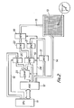
- the shift control system for the keyboard includes a central processing unit (CPU) 11, a keyboard controller 12 and a scan type keyboard 13.
- the keyboard controller 12 is a programmable interface device designed to interface the keyboard 13 and the CPU 11.
- the keyboard controller 12 includes a scanning counter to count the number of the keys.
- the key matrix of the keyboard 13 includes at least one shift key in addition to plural character keys.
- the scan lines 14 provide scanning signals to the encoder 21 via the register 17.
- the return lines 15 provide raw key data to the encoder 22 via the register 18.
- the control line 16 provides a control signal to the register 20 from the CPU 11.
- the outputs of the encoders 21 and 22 are coupled to the comparator 23 and the keyboard controller 12 through the register 19.
- the comparator 23 has another input from the register 20.
- the CPU 11 writes the matrix code identifying the matrix position of the shift-key into the register 20.
- the comparator 23 compares the return data with the matrix code of the shift key to determine if the shift key has just been operated.
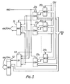
- FIG 3 another embodiment of the invention is shown in block diagram form.
- the difference between the embodiments of Figure 2 and Figure 3 is that in the Figure 2 embodiment there is one shift key, however, in the embodiment in Figure 3 there are plural shift keys.
- registers 20 1 - 20 n and comparators 23 1 - 23 n there are provided respective registers 20 1 - 20 n and comparators 23 1 - 23 n .
- the outputs of the comparators are applied as inputs to the OR gate 33.
- the register 31 is a status register provided to indicate the status of each of the shift keys.
- the output of the OR gate 33 is supplied to the register 32 along with the outputs of the register 19 which instantly latches the outputs of the encoders 21 and 22.
- register 32 stores not only the contents latched in the register 19 but also stores an output of the OR gate 33, such that if one of the shift keys has been operated the most significant bit of the register 32 is "1".
- the CPU 11 preliminarily writes the matrix code of the shift key designated by the programs into the register 20.
- the writing of the shift key matrix code is controlled by the control signal 16 and defines the position of the shift key in the key matrix.
- the keyboard controller 12 begins to scan the key matrix 13. If there are any keys pushed down, the return lines 15 transfer the signals.
- the return signals are stored in the register 18 and are coded by the encoder 22. While the codes of the return lines are being made, the scan lines 14 are stored in the register 17 and are coded by the encoder 21.
- the outputs of both encoders 21 and 22 are stored in the register 19.
- the keyboard controller 12 transmits the keycodes including the status of the shift key to the CPU.
- the keyboard controller controls the registers 17, 18 and 19 and the comparator 23 by the control timing signals 24.
- the register 31 is provided to indicate the status of the shift keys, that is, which shift key is depressed.
- the bit corresponding to a respective depressed shift key is set to "I".
- the register 31 must have a number of bits equal to the number of shift keys.
- the register 32 stores the keycodes and is designed such that if one of the shift keys is operated the most significant bit becomes "1".
- the keyboard controller 12 operates to make its most significant output bit "1". If the most significant bit of the register 32 is "1", the keyboard controller sends the data of register 32 to the CPU and then also sends the contents of the register 31 to the CPU 11.
- the keyboard controller does not send the register 31 data to the CPU since no shift key is depressed. If the CPU 11 receives the date of register 32 in which the most significant bit is "1" from the keyboard controller 12, the CPU 11 only generates the keycodes after receiving the corresponding shift status data. If the CPU 11 receives the data of register 37 in which the most significant bit is "0” the CPU 11 generates the keycodes immediately, concluding that no shift key is depressed.
- the operation of any of the shift keys is indicated by the most significant bit of the register 32, others of the bits can be used for this purpose, for example, the least significant bit or another intermediate bit. Further, it is a simple design task to employ negative logic in the control operations. These alternatives can be accommodated under control of the CPU.
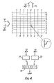
- each of the scan lines 14 (0 - 11) and the return lines 15 (0 - 7) are "1". If the scan line 4 becomes "0", the return lines 3 becomes "0" at the depressed key.
- the encoders 21 and 22 read the number 4 (0100) of the scan lines 14 and the number 3 (011) of the return lines 15 and make their respective coding.
- the register 19 has eight bits for the convenience of the keyboard controller 12, the number of bits can be selected based on user convenience. Namely in the embodiment although the number of scan lines is sixteen and there are eight return lines, if more lines are needed, the additional lines can be accommodated by increasing the number of bits of the register 19.
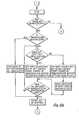
- the keyboard controller employs a single chip microprocessor 41. Operation of this embodiment is explained next referring to the flow chart of the firmware operations shown in Figure 6.
- the keyboard controller itself compares the shift codes with the scanned codes, whereby the hardware is simplified.
- the CPU When the CPU is initiallised by being provided with a source program, it send the matrix codes of the shift key preliminarily determined by the source program to the microprocessor 41.
- the microprocessor 41 stores the data in its memory.
- the microprocessor 41 scans the key matrix and finds a depressed key, the microprocessor 41 compares the codes of the depressed key with the matrix codes of the shift key stored in memory.
- the processor 41 If the microprocessor 41 detects a comparison coincidence, the processor 41 turns on a shift bit in the status area of the memory and scans the depressed keys. If plural shift keys are depressed, the microprocessor 41 turns on the corresponding shift bits of the status area allocated in the memory to the shift keys. Then as shown in Figure 3 the microprocessor reads the data other than the shift keys and makes the most significant bit of the data sent to the CPU "1", and after this operation the microprocessor sends this data to the CPU 11 and then also sends the contents of the shift status area to the CPU. The CPU 11 generates the corresponding keycodes based on the two sets of data.
- the microprocessor makes the most significant bit of the data sent to the CPU "0" and then sends this data to the CPU without any data from the status area.
- the CPU 11 can then determine whether or not a shift key is depressed and can thereby ascertain proper keycodes. If only shift keys are depressed, the microprocessor 41 does not send the key data.
- the keyboard coantroller makes the most significant bit of the matrix code "1" when the shift key is depressed and sends them to the CPU 11 with the shift status data
- the microprocessor initially notifies the CPU which shift key is depressed and thereafter sends only the matrix codes.
- a keyboard controller is necessary in order to send the data to the CPU 11 when the shift key is released.
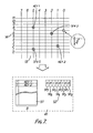
- FIG. 7 the processing of the embodiment in Figure 5 is described next in more detail.
- the shift keys SFK 2 and SFK 5 and keys KEY 1 and KEY 2 of the key matrix 13 are shown depressed.
- the memory of the microprocessor 41 shown schematically encircled by a dashed line, provides a buffer 51 for transmission and a buffer 52 for the shift key status as shown in the memory map.
- the microprocessor 41 scans the key matrix 13 and confirms the four keys depressed.
- the microprocessor compares the scanned key matrix codes with the shift key matrix code data preliminarily sent from the CPU to.detect a shift key depression and to set the particular bit of the buffer 52 indicative of the shift key status.
- the processor sets the bits corresponding to SF 2 and SF S .
- the processor stores the key matrix codes KEY 1 and KEY 2 in the buffer 51 for transmission without the shift matrix codes.
- the processor 41 transmits this data to the CPU 11 with the transmission states shown in the Figure 8.
- the keycodes KEY 1 and KEY 2 are coded as explained in Figure 4.
- the microprocessor 41 transmits the matrix codes of the KEY 1 first with the most significant bit set to indicate shift key depression and then sends the shift status.
- the microprocessor 41 then notifies the CPU of the matrix codes and the shift status of the other depressed keys in successive operations.
- the CPU preliminarily notifies the KBC of the matrix codes of the shift keys.
Applications Claiming Priority (2)
| Application Number | Priority Date | Filing Date | Title |
|---|---|---|---|
| JP56071443A JPS57187732A (en) | 1981-05-14 | 1981-05-14 | Shift control system for keyboard |
| JP71443/81 | 1981-05-14 |
Publications (2)
| Publication Number | Publication Date |
|---|---|
| EP0067516A1 true EP0067516A1 (de) | 1982-12-22 |
| EP0067516B1 EP0067516B1 (de) | 1986-08-27 |
Family
ID=13460681
Family Applications (1)
| Application Number | Title | Priority Date | Filing Date |
|---|---|---|---|
| EP82302295A Expired EP0067516B1 (de) | 1981-05-14 | 1982-05-05 | Tastaturshiftkontrollvorrichtung |
Country Status (4)
| Country | Link |
|---|---|
| US (1) | US4470038A (de) |
| EP (1) | EP0067516B1 (de) |
| JP (1) | JPS57187732A (de) |
| DE (1) | DE3272843D1 (de) |
Cited By (3)
| Publication number | Priority date | Publication date | Assignee | Title |
|---|---|---|---|---|
| EP0232862A2 (de) * | 1986-02-11 | 1987-08-19 | Wilhelm Ruf KG | Universell programmierbare Tastatur |
| EP0254387A2 (de) * | 1986-04-14 | 1988-01-27 | Christopher L. Wolf | Vorrichtung zur Betriebsänderung einer Computertastatur |
| EP0292238A2 (de) * | 1987-05-19 | 1988-11-23 | Brother Kogyo Kabushiki Kaisha | Dateneinführungsvorrichtung mit Matrixabtastungsmitteln |
Families Citing this family (11)
| Publication number | Priority date | Publication date | Assignee | Title |
|---|---|---|---|---|
| JPS5949633A (ja) * | 1982-09-14 | 1984-03-22 | Toshiba Corp | リピ−ト制御方式 |
| JPS61107417A (ja) * | 1984-10-30 | 1986-05-26 | Toshiba Corp | キ−ボ−ド制御方式 |
| US4706068A (en) * | 1985-01-30 | 1987-11-10 | Wyse Technology, Inc. | Four wire keyboard interface |
| US4896290A (en) * | 1987-08-24 | 1990-01-23 | Wang Laboratories, Inc. | Method for routing events from key strokes in a multi-processing computer systems |
| US5034598A (en) * | 1989-12-29 | 1991-07-23 | Hewlett-Packard Company | Keyboard emulation system providing audible feedback without a built-in transducer |
| US5309566A (en) * | 1992-02-04 | 1994-05-03 | International Business Machines Corporation | System and method for character translation |
| US5613135A (en) * | 1992-09-17 | 1997-03-18 | Kabushiki Kaisha Toshiba | Portable computer having dedicated register group and peripheral controller bus between system bus and peripheral controller |
| KR960008975B1 (en) * | 1994-02-03 | 1996-07-10 | Lg Electronics Inc | Encode key input apparatus for microwave oven |
| KR0142370B1 (ko) * | 1995-01-20 | 1998-07-01 | 김광호 | 휴대용 컴퓨터에서 하드웨어 커서를 이용한 피엠에스 레벨표시 장치 및 그 방법 |
| US5659308A (en) * | 1995-06-09 | 1997-08-19 | Vlsi Technology, Inc. | Keyboard scan code translation system and method |
| US5862320A (en) * | 1995-12-22 | 1999-01-19 | Cirrus Logic, Inc. | SDRAM DIMM presence detect interface |
Citations (2)
| Publication number | Priority date | Publication date | Assignee | Title |
|---|---|---|---|---|
| US4200913A (en) * | 1977-04-13 | 1980-04-29 | International Business Machines Corporation | Operator controlled programmable keyboard apparatus |
| EP0011307A2 (de) * | 1978-11-21 | 1980-05-28 | International Business Machines Corporation | Verfahren und Vorrichtung zur Erzeugung von Zeichenkoden |
Family Cites Families (5)
| Publication number | Priority date | Publication date | Assignee | Title |
|---|---|---|---|---|
| US3742137A (en) * | 1970-07-29 | 1973-06-26 | Teletype Corp | Case shifting code generator |
| FR2144094A5 (de) * | 1971-06-30 | 1973-02-09 | Honeywell Bull Soc Ind | |
| US3778819A (en) * | 1972-11-17 | 1973-12-11 | Ibm | Keyboard with four character set shift |
| US4121048A (en) * | 1977-07-28 | 1978-10-17 | Ncr Corporation | Multiple shift electronic keyboard |
| JPS569827A (en) * | 1979-07-02 | 1981-01-31 | Ricoh Co Ltd | Key input control system |
-
1981
- 1981-05-14 JP JP56071443A patent/JPS57187732A/ja active Pending
-
1982
- 1982-03-24 US US06/361,247 patent/US4470038A/en not_active Expired - Fee Related
- 1982-05-05 DE DE8282302295T patent/DE3272843D1/de not_active Expired
- 1982-05-05 EP EP82302295A patent/EP0067516B1/de not_active Expired
Patent Citations (2)
| Publication number | Priority date | Publication date | Assignee | Title |
|---|---|---|---|---|
| US4200913A (en) * | 1977-04-13 | 1980-04-29 | International Business Machines Corporation | Operator controlled programmable keyboard apparatus |
| EP0011307A2 (de) * | 1978-11-21 | 1980-05-28 | International Business Machines Corporation | Verfahren und Vorrichtung zur Erzeugung von Zeichenkoden |
Non-Patent Citations (1)
| Title |
|---|
| IBM TECHNICAL DISCLOSURE BULLETIN, vol. 23, no. 7A, December 1980, pages 2937-2939, New York, (USA) * |
Cited By (6)
| Publication number | Priority date | Publication date | Assignee | Title |
|---|---|---|---|---|
| EP0232862A2 (de) * | 1986-02-11 | 1987-08-19 | Wilhelm Ruf KG | Universell programmierbare Tastatur |
| EP0232862A3 (de) * | 1986-02-11 | 1990-01-31 | Wilhelm Ruf KG | Universell programmierbare Tastatur |
| EP0254387A2 (de) * | 1986-04-14 | 1988-01-27 | Christopher L. Wolf | Vorrichtung zur Betriebsänderung einer Computertastatur |
| EP0254387A3 (de) * | 1986-04-14 | 1989-11-15 | Christopher L. Wolf | Vorrichtung zur Betriebsänderung einer Computertastatur |
| EP0292238A2 (de) * | 1987-05-19 | 1988-11-23 | Brother Kogyo Kabushiki Kaisha | Dateneinführungsvorrichtung mit Matrixabtastungsmitteln |
| EP0292238A3 (en) * | 1987-05-19 | 1990-02-14 | Brother Kogyo Kabushiki Kaisha | Data input device having switch matrix scanning means |
Also Published As
| Publication number | Publication date |
|---|---|
| DE3272843D1 (en) | 1986-10-02 |
| JPS57187732A (en) | 1982-11-18 |
| US4470038A (en) | 1984-09-04 |
| EP0067516B1 (de) | 1986-08-27 |
Similar Documents
| Publication | Publication Date | Title |
|---|---|---|
| EP0067516B1 (de) | Tastaturshiftkontrollvorrichtung | |
| CA1073554A (en) | Keyboard circuit | |
| US4502038A (en) | Keyboard scanning and interface method and circuit | |
| US4680572A (en) | Chord entry keying of data fields | |
| EP0352028B1 (de) | Vorrichtung für die Datenübertragung zwischen einem Zentralprozessor und entfernen Peripheriegeräten | |
| US4922248A (en) | Key output method for keyboards | |
| EP0055560A2 (de) | Dateneingabevorrichtung | |
| GB2125199A (en) | Input device | |
| US5220323A (en) | Keyboard apparatus having ghost key sensing function | |
| US3706973A (en) | Dynamic keyboard data entry system | |
| US4121048A (en) | Multiple shift electronic keyboard | |
| US3952289A (en) | Controller for linking a typewriter console to a processor unit | |
| EP0325884B1 (de) | Tastatur mit Geistertasten-Feststellung | |
| US6831630B2 (en) | Key input device having Braille input function | |
| EP0229695B1 (de) | Matrixumschaltvorrichtung mit Beseitigung von falschen Eingängen | |
| JPH07504775A (ja) | キーボードインターフェースを介しての入力装置の制御方法 | |
| KR20010108593A (ko) | 한글 입출력 장치 및 방법 | |
| EP0039233A2 (de) | Dateneingabegerät | |
| US4374429A (en) | Information transfer system wherein bidirectional transfer is effected utilizing unidirectional bus in conjunction with key depression signal line | |
| JPS6155725A (ja) | キ−ボ−ド装置 | |
| GB2263990A (en) | Method for detecting ghost keys | |
| KR100196665B1 (ko) | 무선 키 보드의 시스템 스캔 데이타 송신 방법 | |
| JP2699752B2 (ja) | キーボード装置 | |
| GB2078617A (en) | Keyboard terminal unit | |
| KR900000604B1 (ko) | 키 입력 데이타 처리회로 |
Legal Events
| Date | Code | Title | Description |
|---|---|---|---|
| PUAI | Public reference made under article 153(3) epc to a published international application that has entered the european phase |
Free format text: ORIGINAL CODE: 0009012 |
|
| AK | Designated contracting states |
Designated state(s): DE FR GB |
|
| 17P | Request for examination filed |
Effective date: 19830603 |
|
| RAP1 | Party data changed (applicant data changed or rights of an application transferred) |
Owner name: KABUSHIKI KAISHA TOSHIBA |
|
| GRAA | (expected) grant |
Free format text: ORIGINAL CODE: 0009210 |
|
| DET | De: translation of patent claims | ||
| AK | Designated contracting states |
Kind code of ref document: B1 Designated state(s): DE FR GB |
|
| ET | Fr: translation filed | ||
| REF | Corresponds to: |
Ref document number: 3272843 Country of ref document: DE Date of ref document: 19861002 |
|
| PLBE | No opposition filed within time limit |
Free format text: ORIGINAL CODE: 0009261 |
|
| STAA | Information on the status of an ep patent application or granted ep patent |
Free format text: STATUS: NO OPPOSITION FILED WITHIN TIME LIMIT |
|
| 26N | No opposition filed | ||
| PGFP | Annual fee paid to national office [announced via postgrant information from national office to epo] |
Ref country code: GB Payment date: 19940426 Year of fee payment: 13 |
|
| PGFP | Annual fee paid to national office [announced via postgrant information from national office to epo] |
Ref country code: FR Payment date: 19940511 Year of fee payment: 13 Ref country code: DE Payment date: 19940511 Year of fee payment: 13 |
|
| PG25 | Lapsed in a contracting state [announced via postgrant information from national office to epo] |
Ref country code: GB Effective date: 19950505 |
|
| GBPC | Gb: european patent ceased through non-payment of renewal fee |
Effective date: 19950505 |
|
| PG25 | Lapsed in a contracting state [announced via postgrant information from national office to epo] |
Ref country code: DE Effective date: 19960201 |
|
| PG25 | Lapsed in a contracting state [announced via postgrant information from national office to epo] |
Ref country code: FR Effective date: 19960229 |
|
| REG | Reference to a national code |
Ref country code: FR Ref legal event code: ST |
|
| REG | Reference to a national code |
Ref country code: FR Ref legal event code: ST |