CN107438404B - Electromechanical pill device with positioning capability - Google Patents
Electromechanical pill device with positioning capability Download PDFInfo
- Publication number
- CN107438404B CN107438404B CN201580063563.8A CN201580063563A CN107438404B CN 107438404 B CN107438404 B CN 107438404B CN 201580063563 A CN201580063563 A CN 201580063563A CN 107438404 B CN107438404 B CN 107438404B
- Authority
- CN
- China
- Prior art keywords
- ingestible device
- radial
- reflectance
- data set
- axial
- Prior art date
- Legal status (The legal status is an assumption and is not a legal conclusion. Google has not performed a legal analysis and makes no representation as to the accuracy of the status listed.)
- Active
Links
- 239000006187 pill Substances 0.000 title description 5
- 238000005286 illumination Methods 0.000 claims abstract description 241
- 210000001035 gastrointestinal tract Anatomy 0.000 claims abstract description 143
- 230000003287 optical effect Effects 0.000 claims abstract description 56
- 230000007704 transition Effects 0.000 claims description 120
- 210000002784 stomach Anatomy 0.000 claims description 103
- 238000012545 processing Methods 0.000 claims description 96
- 210000001198 duodenum Anatomy 0.000 claims description 37
- 238000005070 sampling Methods 0.000 claims description 34
- 238000001228 spectrum Methods 0.000 claims description 34
- 230000008859 change Effects 0.000 claims description 33
- 210000001630 jejunum Anatomy 0.000 claims description 28
- 210000004534 cecum Anatomy 0.000 claims description 25
- 238000002329 infrared spectrum Methods 0.000 claims description 12
- 210000003405 ileum Anatomy 0.000 claims description 9
- 210000003041 ligament Anatomy 0.000 claims description 7
- 238000000034 method Methods 0.000 abstract description 141
- 239000002245 particle Substances 0.000 abstract description 30
- 239000003814 drug Substances 0.000 abstract description 19
- 239000012530 fluid Substances 0.000 abstract description 8
- 210000000056 organ Anatomy 0.000 abstract description 8
- 238000002310 reflectometry Methods 0.000 description 146
- 210000000813 small intestine Anatomy 0.000 description 95
- 238000004422 calculation algorithm Methods 0.000 description 80
- 238000004891 communication Methods 0.000 description 80
- 238000001514 detection method Methods 0.000 description 50
- 210000002429 large intestine Anatomy 0.000 description 46
- 230000015654 memory Effects 0.000 description 45
- 230000008569 process Effects 0.000 description 41
- 239000000463 material Substances 0.000 description 39
- 239000000126 substance Substances 0.000 description 38
- 238000003860 storage Methods 0.000 description 36
- 238000010586 diagram Methods 0.000 description 31
- 238000012384 transportation and delivery Methods 0.000 description 28
- MTLMVEWEYZFYTH-UHFFFAOYSA-N 1,3,5-trichloro-2-phenylbenzene Chemical compound ClC1=CC(Cl)=CC(Cl)=C1C1=CC=CC=C1 MTLMVEWEYZFYTH-UHFFFAOYSA-N 0.000 description 27
- 230000002093 peripheral effect Effects 0.000 description 25
- 230000004044 response Effects 0.000 description 25
- 210000001519 tissue Anatomy 0.000 description 24
- 230000006870 function Effects 0.000 description 22
- 238000001727 in vivo Methods 0.000 description 18
- 230000033001 locomotion Effects 0.000 description 18
- 238000011022 operating instruction Methods 0.000 description 16
- NDVLTYZPCACLMA-UHFFFAOYSA-N silver oxide Chemical compound [O-2].[Ag+].[Ag+] NDVLTYZPCACLMA-UHFFFAOYSA-N 0.000 description 16
- 238000001579 optical reflectometry Methods 0.000 description 15
- 230000002183 duodenal effect Effects 0.000 description 14
- 238000004519 manufacturing process Methods 0.000 description 13
- 230000002496 gastric effect Effects 0.000 description 12
- 238000012360 testing method Methods 0.000 description 12
- 230000007423 decrease Effects 0.000 description 11
- 238000013461 design Methods 0.000 description 11
- 239000007788 liquid Substances 0.000 description 11
- 230000000694 effects Effects 0.000 description 9
- 229910001923 silver oxide Inorganic materials 0.000 description 9
- 230000005540 biological transmission Effects 0.000 description 8
- 230000004807 localization Effects 0.000 description 8
- 238000010521 absorption reaction Methods 0.000 description 7
- 229920005573 silicon-containing polymer Polymers 0.000 description 7
- 230000036760 body temperature Effects 0.000 description 6
- 208000037265 diseases, disorders, signs and symptoms Diseases 0.000 description 6
- 239000010410 layer Substances 0.000 description 6
- 230000000670 limiting effect Effects 0.000 description 6
- 238000005259 measurement Methods 0.000 description 6
- 239000008177 pharmaceutical agent Substances 0.000 description 6
- 239000000853 adhesive Substances 0.000 description 5
- 230000001070 adhesive effect Effects 0.000 description 5
- 238000003556 assay Methods 0.000 description 5
- 238000009529 body temperature measurement Methods 0.000 description 5
- 235000013305 food Nutrition 0.000 description 5
- 210000001187 pylorus Anatomy 0.000 description 5
- 230000002829 reductive effect Effects 0.000 description 5
- 229940124597 therapeutic agent Drugs 0.000 description 5
- 238000011282 treatment Methods 0.000 description 5
- 238000001429 visible spectrum Methods 0.000 description 5
- 230000006399 behavior Effects 0.000 description 4
- 230000008901 benefit Effects 0.000 description 4
- -1 but not limited to Substances 0.000 description 4
- 239000002775 capsule Substances 0.000 description 4
- 210000001072 colon Anatomy 0.000 description 4
- 201000010099 disease Diseases 0.000 description 4
- 238000001914 filtration Methods 0.000 description 4
- 239000006260 foam Substances 0.000 description 4
- 230000003993 interaction Effects 0.000 description 4
- 210000004347 intestinal mucosa Anatomy 0.000 description 4
- 230000037361 pathway Effects 0.000 description 4
- 239000002861 polymer material Substances 0.000 description 4
- 239000003826 tablet Substances 0.000 description 4
- 241000252983 Caecum Species 0.000 description 3
- 229920001651 Cyanoacrylate Polymers 0.000 description 3
- MWCLLHOVUTZFKS-UHFFFAOYSA-N Methyl cyanoacrylate Chemical compound COC(=O)C(=C)C#N MWCLLHOVUTZFKS-UHFFFAOYSA-N 0.000 description 3
- 108010001267 Protein Subunits Proteins 0.000 description 3
- 238000012952 Resampling Methods 0.000 description 3
- 238000000692 Student's t-test Methods 0.000 description 3
- 230000005856 abnormality Effects 0.000 description 3
- 238000002835 absorbance Methods 0.000 description 3
- 230000003213 activating effect Effects 0.000 description 3
- 238000004458 analytical method Methods 0.000 description 3
- 239000003990 capacitor Substances 0.000 description 3
- 210000003608 fece Anatomy 0.000 description 3
- 230000005055 memory storage Effects 0.000 description 3
- 238000012544 monitoring process Methods 0.000 description 3
- 210000000214 mouth Anatomy 0.000 description 3
- 210000004872 soft tissue Anatomy 0.000 description 3
- 238000012353 t test Methods 0.000 description 3
- XLYOFNOQVPJJNP-UHFFFAOYSA-N water Substances O XLYOFNOQVPJJNP-UHFFFAOYSA-N 0.000 description 3
- 230000005355 Hall effect Effects 0.000 description 2
- VEXZGXHMUGYJMC-UHFFFAOYSA-N Hydrochloric acid Chemical compound Cl VEXZGXHMUGYJMC-UHFFFAOYSA-N 0.000 description 2
- WHXSMMKQMYFTQS-UHFFFAOYSA-N Lithium Chemical compound [Li] WHXSMMKQMYFTQS-UHFFFAOYSA-N 0.000 description 2
- 239000004698 Polyethylene Substances 0.000 description 2
- 239000012491 analyte Substances 0.000 description 2
- 210000003484 anatomy Anatomy 0.000 description 2
- 230000001580 bacterial effect Effects 0.000 description 2
- 239000000560 biocompatible material Substances 0.000 description 2
- 239000003124 biologic agent Substances 0.000 description 2
- 238000004364 calculation method Methods 0.000 description 2
- 229910052799 carbon Inorganic materials 0.000 description 2
- 239000003153 chemical reaction reagent Substances 0.000 description 2
- 239000003795 chemical substances by application Substances 0.000 description 2
- 235000020965 cold beverage Nutrition 0.000 description 2
- 239000003086 colorant Substances 0.000 description 2
- 238000011960 computer-aided design Methods 0.000 description 2
- 238000010276 construction Methods 0.000 description 2
- 230000001276 controlling effect Effects 0.000 description 2
- 239000004205 dimethyl polysiloxane Substances 0.000 description 2
- 238000007599 discharging Methods 0.000 description 2
- 208000035475 disorder Diseases 0.000 description 2
- 230000037406 food intake Effects 0.000 description 2
- 230000030136 gastric emptying Effects 0.000 description 2
- 238000003384 imaging method Methods 0.000 description 2
- 230000003100 immobilizing effect Effects 0.000 description 2
- 230000000977 initiatory effect Effects 0.000 description 2
- 230000010354 integration Effects 0.000 description 2
- 230000002452 interceptive effect Effects 0.000 description 2
- 230000000968 intestinal effect Effects 0.000 description 2
- 229910052744 lithium Inorganic materials 0.000 description 2
- 239000000203 mixture Substances 0.000 description 2
- 239000000178 monomer Substances 0.000 description 2
- 210000003097 mucus Anatomy 0.000 description 2
- OTCVAHKKMMUFAY-UHFFFAOYSA-N oxosilver Chemical compound [Ag]=O OTCVAHKKMMUFAY-UHFFFAOYSA-N 0.000 description 2
- 229920003023 plastic Polymers 0.000 description 2
- 239000004033 plastic Substances 0.000 description 2
- 229920000435 poly(dimethylsiloxane) Polymers 0.000 description 2
- 229920003229 poly(methyl methacrylate) Polymers 0.000 description 2
- 239000004417 polycarbonate Substances 0.000 description 2
- 229920000515 polycarbonate Polymers 0.000 description 2
- 229920000573 polyethylene Polymers 0.000 description 2
- 229920000642 polymer Polymers 0.000 description 2
- 239000004926 polymethyl methacrylate Substances 0.000 description 2
- 229920001296 polysiloxane Polymers 0.000 description 2
- 229920001343 polytetrafluoroethylene Polymers 0.000 description 2
- 239000004810 polytetrafluoroethylene Substances 0.000 description 2
- 239000000843 powder Substances 0.000 description 2
- 210000000664 rectum Anatomy 0.000 description 2
- 230000009467 reduction Effects 0.000 description 2
- 238000000926 separation method Methods 0.000 description 2
- 238000012546 transfer Methods 0.000 description 2
- 238000007514 turning Methods 0.000 description 2
- RVCKCEDKBVEEHL-UHFFFAOYSA-N 2,3,4,5,6-pentachlorobenzyl alcohol Chemical compound OCC1=C(Cl)C(Cl)=C(Cl)C(Cl)=C1Cl RVCKCEDKBVEEHL-UHFFFAOYSA-N 0.000 description 1
- ZCJJIQHVZCFSGZ-UHFFFAOYSA-N 2,8-bis(diphenylphosphoryl)dibenzothiophene Chemical compound C=1C=CC=CC=1P(C=1C=C2C3=CC(=CC=C3SC2=CC=1)P(=O)(C=1C=CC=CC=1)C=1C=CC=CC=1)(=O)C1=CC=CC=C1 ZCJJIQHVZCFSGZ-UHFFFAOYSA-N 0.000 description 1
- 238000010146 3D printing Methods 0.000 description 1
- 238000012935 Averaging Methods 0.000 description 1
- 208000015943 Coeliac disease Diseases 0.000 description 1
- 206010010774 Constipation Diseases 0.000 description 1
- 208000011231 Crohn disease Diseases 0.000 description 1
- 208000002699 Digestive System Neoplasms Diseases 0.000 description 1
- 206010021518 Impaired gastric emptying Diseases 0.000 description 1
- 206010061218 Inflammation Diseases 0.000 description 1
- 239000004944 Liquid Silicone Rubber Substances 0.000 description 1
- 241001465754 Metazoa Species 0.000 description 1
- 208000012868 Overgrowth Diseases 0.000 description 1
- 208000032366 Oversensing Diseases 0.000 description 1
- 229920012266 Poly(ether sulfone) PES Polymers 0.000 description 1
- 241000550081 Renata Species 0.000 description 1
- YZSKZXUDGLALTQ-UHFFFAOYSA-N [Li][C] Chemical compound [Li][C] YZSKZXUDGLALTQ-UHFFFAOYSA-N 0.000 description 1
- 230000002159 abnormal effect Effects 0.000 description 1
- 230000009471 action Effects 0.000 description 1
- 230000004913 activation Effects 0.000 description 1
- 238000001994 activation Methods 0.000 description 1
- 230000002411 adverse Effects 0.000 description 1
- 210000000436 anus Anatomy 0.000 description 1
- 238000013459 approach Methods 0.000 description 1
- 210000001142 back Anatomy 0.000 description 1
- 210000000941 bile Anatomy 0.000 description 1
- 238000012742 biochemical analysis Methods 0.000 description 1
- 230000004071 biological effect Effects 0.000 description 1
- 239000000090 biomarker Substances 0.000 description 1
- 239000008280 blood Substances 0.000 description 1
- 210000004369 blood Anatomy 0.000 description 1
- 239000005388 borosilicate glass Substances 0.000 description 1
- 238000005266 casting Methods 0.000 description 1
- 230000015556 catabolic process Effects 0.000 description 1
- 238000001311 chemical methods and process Methods 0.000 description 1
- 235000021270 cold food Nutrition 0.000 description 1
- 206010009887 colitis Diseases 0.000 description 1
- 230000006835 compression Effects 0.000 description 1
- 238000007906 compression Methods 0.000 description 1
- 238000004590 computer program Methods 0.000 description 1
- 239000000470 constituent Substances 0.000 description 1
- 238000007796 conventional method Methods 0.000 description 1
- 238000012937 correction Methods 0.000 description 1
- 230000008878 coupling Effects 0.000 description 1
- 238000010168 coupling process Methods 0.000 description 1
- 238000005859 coupling reaction Methods 0.000 description 1
- 238000012864 cross contamination Methods 0.000 description 1
- 238000013480 data collection Methods 0.000 description 1
- 230000003247 decreasing effect Effects 0.000 description 1
- 238000006731 degradation reaction Methods 0.000 description 1
- 238000011161 development Methods 0.000 description 1
- 238000003745 diagnosis Methods 0.000 description 1
- 230000035622 drinking Effects 0.000 description 1
- 229940079593 drug Drugs 0.000 description 1
- 230000009977 dual effect Effects 0.000 description 1
- 229920001971 elastomer Polymers 0.000 description 1
- 239000000806 elastomer Substances 0.000 description 1
- 238000005516 engineering process Methods 0.000 description 1
- 230000002255 enzymatic effect Effects 0.000 description 1
- 210000003238 esophagus Anatomy 0.000 description 1
- 238000000605 extraction Methods 0.000 description 1
- 239000004744 fabric Substances 0.000 description 1
- 239000011152 fibreglass Substances 0.000 description 1
- 229920002457 flexible plastic Polymers 0.000 description 1
- 239000004811 fluoropolymer Substances 0.000 description 1
- 229920002313 fluoropolymer Polymers 0.000 description 1
- 210000004051 gastric juice Anatomy 0.000 description 1
- 210000001156 gastric mucosa Anatomy 0.000 description 1
- 210000003736 gastrointestinal content Anatomy 0.000 description 1
- 208000001288 gastroparesis Diseases 0.000 description 1
- 239000011521 glass Substances 0.000 description 1
- 239000000383 hazardous chemical Substances 0.000 description 1
- 230000036541 health Effects 0.000 description 1
- 230000002209 hydrophobic effect Effects 0.000 description 1
- 210000003692 ilium Anatomy 0.000 description 1
- 239000007943 implant Substances 0.000 description 1
- 239000012535 impurity Substances 0.000 description 1
- 230000006698 induction Effects 0.000 description 1
- 230000004054 inflammatory process Effects 0.000 description 1
- 238000001746 injection moulding Methods 0.000 description 1
- 238000009434 installation Methods 0.000 description 1
- 230000001788 irregular Effects 0.000 description 1
- 230000031700 light absorption Effects 0.000 description 1
- 238000012886 linear function Methods 0.000 description 1
- 238000010801 machine learning Methods 0.000 description 1
- 238000003754 machining Methods 0.000 description 1
- 239000003550 marker Substances 0.000 description 1
- 235000012054 meals Nutrition 0.000 description 1
- 230000007246 mechanism Effects 0.000 description 1
- 230000004060 metabolic process Effects 0.000 description 1
- 229910052751 metal Inorganic materials 0.000 description 1
- 239000002184 metal Substances 0.000 description 1
- 150000002739 metals Chemical class 0.000 description 1
- 238000003801 milling Methods 0.000 description 1
- 238000012986 modification Methods 0.000 description 1
- 230000004048 modification Effects 0.000 description 1
- 230000004899 motility Effects 0.000 description 1
- 238000000465 moulding Methods 0.000 description 1
- 230000004118 muscle contraction Effects 0.000 description 1
- 235000015097 nutrients Nutrition 0.000 description 1
- 210000004789 organ system Anatomy 0.000 description 1
- 230000001575 pathological effect Effects 0.000 description 1
- 230000002572 peristaltic effect Effects 0.000 description 1
- 210000003800 pharynx Anatomy 0.000 description 1
- 108091008695 photoreceptors Proteins 0.000 description 1
- 230000001766 physiological effect Effects 0.000 description 1
- 238000000678 plasma activation Methods 0.000 description 1
- 229920000058 polyacrylate Polymers 0.000 description 1
- 239000004814 polyurethane Substances 0.000 description 1
- 239000004800 polyvinyl chloride Substances 0.000 description 1
- 238000013105 post hoc analysis Methods 0.000 description 1
- 230000001681 protective effect Effects 0.000 description 1
- 239000011241 protective layer Substances 0.000 description 1
- 108090000623 proteins and genes Proteins 0.000 description 1
- 102000004169 proteins and genes Human genes 0.000 description 1
- 230000007420 reactivation Effects 0.000 description 1
- 230000001105 regulatory effect Effects 0.000 description 1
- 230000002787 reinforcement Effects 0.000 description 1
- 238000011160 research Methods 0.000 description 1
- 238000012552 review Methods 0.000 description 1
- 238000007789 sealing Methods 0.000 description 1
- 229910052710 silicon Inorganic materials 0.000 description 1
- 239000010703 silicon Substances 0.000 description 1
- 229920002379 silicone rubber Polymers 0.000 description 1
- 210000002460 smooth muscle Anatomy 0.000 description 1
- 239000007787 solid Substances 0.000 description 1
- 210000005070 sphincter Anatomy 0.000 description 1
- 239000010935 stainless steel Substances 0.000 description 1
- 229910001220 stainless steel Inorganic materials 0.000 description 1
- 239000003351 stiffener Substances 0.000 description 1
- 230000000153 supplemental effect Effects 0.000 description 1
- 230000001360 synchronised effect Effects 0.000 description 1
- 230000001839 systemic circulation Effects 0.000 description 1
- 229920001169 thermoplastic Polymers 0.000 description 1
- 239000004416 thermosoftening plastic Substances 0.000 description 1
- 231100000331 toxic Toxicity 0.000 description 1
- 230000002588 toxic effect Effects 0.000 description 1
- 230000001052 transient effect Effects 0.000 description 1
- 239000012780 transparent material Substances 0.000 description 1
- 238000002211 ultraviolet spectrum Methods 0.000 description 1
- 230000002618 waking effect Effects 0.000 description 1
- 239000002699 waste material Substances 0.000 description 1
Images


Classifications
-
- A—HUMAN NECESSITIES
- A61—MEDICAL OR VETERINARY SCIENCE; HYGIENE
- A61B—DIAGNOSIS; SURGERY; IDENTIFICATION
- A61B1/00—Instruments for performing medical examinations of the interior of cavities or tubes of the body by visual or photographical inspection, e.g. endoscopes; Illuminating arrangements therefor
- A61B1/04—Instruments for performing medical examinations of the interior of cavities or tubes of the body by visual or photographical inspection, e.g. endoscopes; Illuminating arrangements therefor combined with photographic or television appliances
- A61B1/041—Capsule endoscopes for imaging
-
- A—HUMAN NECESSITIES
- A61—MEDICAL OR VETERINARY SCIENCE; HYGIENE
- A61B—DIAGNOSIS; SURGERY; IDENTIFICATION
- A61B5/00—Measuring for diagnostic purposes; Identification of persons
- A61B5/0002—Remote monitoring of patients using telemetry, e.g. transmission of vital signals via a communication network
- A61B5/0015—Remote monitoring of patients using telemetry, e.g. transmission of vital signals via a communication network characterised by features of the telemetry system
- A61B5/0017—Remote monitoring of patients using telemetry, e.g. transmission of vital signals via a communication network characterised by features of the telemetry system transmitting optical signals
-
- A—HUMAN NECESSITIES
- A61—MEDICAL OR VETERINARY SCIENCE; HYGIENE
- A61B—DIAGNOSIS; SURGERY; IDENTIFICATION
- A61B5/00—Measuring for diagnostic purposes; Identification of persons
- A61B5/0002—Remote monitoring of patients using telemetry, e.g. transmission of vital signals via a communication network
- A61B5/0015—Remote monitoring of patients using telemetry, e.g. transmission of vital signals via a communication network characterised by features of the telemetry system
- A61B5/002—Monitoring the patient using a local or closed circuit, e.g. in a room or building
-
- A—HUMAN NECESSITIES
- A61—MEDICAL OR VETERINARY SCIENCE; HYGIENE
- A61B—DIAGNOSIS; SURGERY; IDENTIFICATION
- A61B5/00—Measuring for diagnostic purposes; Identification of persons
- A61B5/0059—Measuring for diagnostic purposes; Identification of persons using light, e.g. diagnosis by transillumination, diascopy, fluorescence
- A61B5/0082—Measuring for diagnostic purposes; Identification of persons using light, e.g. diagnosis by transillumination, diascopy, fluorescence adapted for particular medical purposes
- A61B5/0084—Measuring for diagnostic purposes; Identification of persons using light, e.g. diagnosis by transillumination, diascopy, fluorescence adapted for particular medical purposes for introduction into the body, e.g. by catheters
- A61B5/0086—Measuring for diagnostic purposes; Identification of persons using light, e.g. diagnosis by transillumination, diascopy, fluorescence adapted for particular medical purposes for introduction into the body, e.g. by catheters using infrared radiation
-
- A—HUMAN NECESSITIES
- A61—MEDICAL OR VETERINARY SCIENCE; HYGIENE
- A61B—DIAGNOSIS; SURGERY; IDENTIFICATION
- A61B5/00—Measuring for diagnostic purposes; Identification of persons
- A61B5/06—Devices, other than using radiation, for detecting or locating foreign bodies ; determining position of probes within or on the body of the patient
- A61B5/065—Determining position of the probe employing exclusively positioning means located on or in the probe, e.g. using position sensors arranged on the probe
-
- A—HUMAN NECESSITIES
- A61—MEDICAL OR VETERINARY SCIENCE; HYGIENE
- A61B—DIAGNOSIS; SURGERY; IDENTIFICATION
- A61B5/00—Measuring for diagnostic purposes; Identification of persons
- A61B5/07—Endoradiosondes
- A61B5/073—Intestinal transmitters
-
- A—HUMAN NECESSITIES
- A61—MEDICAL OR VETERINARY SCIENCE; HYGIENE
- A61B—DIAGNOSIS; SURGERY; IDENTIFICATION
- A61B5/00—Measuring for diagnostic purposes; Identification of persons
- A61B5/68—Arrangements of detecting, measuring or recording means, e.g. sensors, in relation to patient
- A61B5/6846—Arrangements of detecting, measuring or recording means, e.g. sensors, in relation to patient specially adapted to be brought in contact with an internal body part, i.e. invasive
- A61B5/6847—Arrangements of detecting, measuring or recording means, e.g. sensors, in relation to patient specially adapted to be brought in contact with an internal body part, i.e. invasive mounted on an invasive device
- A61B5/6861—Capsules, e.g. for swallowing or implanting
-
- A—HUMAN NECESSITIES
- A61—MEDICAL OR VETERINARY SCIENCE; HYGIENE
- A61B—DIAGNOSIS; SURGERY; IDENTIFICATION
- A61B5/00—Measuring for diagnostic purposes; Identification of persons
- A61B5/72—Signal processing specially adapted for physiological signals or for diagnostic purposes
- A61B5/7235—Details of waveform analysis
- A61B5/7264—Classification of physiological signals or data, e.g. using neural networks, statistical classifiers, expert systems or fuzzy systems
-
- H—ELECTRICITY
- H04—ELECTRIC COMMUNICATION TECHNIQUE
- H04B—TRANSMISSION
- H04B10/00—Transmission systems employing electromagnetic waves other than radio-waves, e.g. infrared, visible or ultraviolet light, or employing corpuscular radiation, e.g. quantum communication
-
- H—ELECTRICITY
- H04—ELECTRIC COMMUNICATION TECHNIQUE
- H04B—TRANSMISSION
- H04B10/00—Transmission systems employing electromagnetic waves other than radio-waves, e.g. infrared, visible or ultraviolet light, or employing corpuscular radiation, e.g. quantum communication
- H04B10/11—Arrangements specific to free-space transmission, i.e. transmission through air or vacuum
- H04B10/114—Indoor or close-range type systems
- H04B10/1143—Bidirectional transmission
-
- H—ELECTRICITY
- H04—ELECTRIC COMMUNICATION TECHNIQUE
- H04B—TRANSMISSION
- H04B13/00—Transmission systems characterised by the medium used for transmission, not provided for in groups H04B3/00 - H04B11/00
-
- A—HUMAN NECESSITIES
- A61—MEDICAL OR VETERINARY SCIENCE; HYGIENE
- A61B—DIAGNOSIS; SURGERY; IDENTIFICATION
- A61B10/00—Other methods or instruments for diagnosis, e.g. instruments for taking a cell sample, for biopsy, for vaccination diagnosis; Sex determination; Ovulation-period determination; Throat striking implements
- A61B10/0045—Devices for taking samples of body liquids
- A61B2010/0061—Alimentary tract secretions, e.g. biliary, gastric, intestinal, pancreatic secretions
-
- A—HUMAN NECESSITIES
- A61—MEDICAL OR VETERINARY SCIENCE; HYGIENE
- A61B—DIAGNOSIS; SURGERY; IDENTIFICATION
- A61B2560/00—Constructional details of operational features of apparatus; Accessories for medical measuring apparatus
- A61B2560/04—Constructional details of apparatus
- A61B2560/0443—Modular apparatus
-
- A—HUMAN NECESSITIES
- A61—MEDICAL OR VETERINARY SCIENCE; HYGIENE
- A61B—DIAGNOSIS; SURGERY; IDENTIFICATION
- A61B2560/00—Constructional details of operational features of apparatus; Accessories for medical measuring apparatus
- A61B2560/04—Constructional details of apparatus
- A61B2560/0462—Apparatus with built-in sensors
-
- A—HUMAN NECESSITIES
- A61—MEDICAL OR VETERINARY SCIENCE; HYGIENE
- A61B—DIAGNOSIS; SURGERY; IDENTIFICATION
- A61B2562/00—Details of sensors; Constructional details of sensor housings or probes; Accessories for sensors
- A61B2562/16—Details of sensor housings or probes; Details of structural supports for sensors
- A61B2562/162—Capsule shaped sensor housings, e.g. for swallowing or implantation
-
- G—PHYSICS
- G16—INFORMATION AND COMMUNICATION TECHNOLOGY [ICT] SPECIALLY ADAPTED FOR SPECIFIC APPLICATION FIELDS
- G16H—HEALTHCARE INFORMATICS, i.e. INFORMATION AND COMMUNICATION TECHNOLOGY [ICT] SPECIALLY ADAPTED FOR THE HANDLING OR PROCESSING OF MEDICAL OR HEALTHCARE DATA
- G16H50/00—ICT specially adapted for medical diagnosis, medical simulation or medical data mining; ICT specially adapted for detecting, monitoring or modelling epidemics or pandemics
- G16H50/20—ICT specially adapted for medical diagnosis, medical simulation or medical data mining; ICT specially adapted for detecting, monitoring or modelling epidemics or pandemics for computer-aided diagnosis, e.g. based on medical expert systems
Landscapes
- Health & Medical Sciences (AREA)
- Life Sciences & Earth Sciences (AREA)
- Engineering & Computer Science (AREA)
- Physics & Mathematics (AREA)
- Surgery (AREA)
- Biophysics (AREA)
- Animal Behavior & Ethology (AREA)
- Public Health (AREA)
- Molecular Biology (AREA)
- General Health & Medical Sciences (AREA)
- Medical Informatics (AREA)
- Heart & Thoracic Surgery (AREA)
- Veterinary Medicine (AREA)
- Pathology (AREA)
- Biomedical Technology (AREA)
- Computer Networks & Wireless Communication (AREA)
- Signal Processing (AREA)
- Artificial Intelligence (AREA)
- Human Computer Interaction (AREA)
- Physiology (AREA)
- Psychiatry (AREA)
- Computer Vision & Pattern Recognition (AREA)
- Mathematical Physics (AREA)
- Nuclear Medicine, Radiotherapy & Molecular Imaging (AREA)
- Optics & Photonics (AREA)
- Radiology & Medical Imaging (AREA)
- Fuzzy Systems (AREA)
- Evolutionary Computation (AREA)
- Electromagnetism (AREA)
- Measurement Of The Respiration, Hearing Ability, Form, And Blood Characteristics Of Living Organisms (AREA)
- Endoscopes (AREA)
- Investigating Or Analysing Materials By Optical Means (AREA)
- Medicines Containing Antibodies Or Antigens For Use As Internal Diagnostic Agents (AREA)
- Infusion, Injection, And Reservoir Apparatuses (AREA)
Abstract
Various embodiments of devices, systems, and methods for identifying a location of an ingestible device within a gastrointestinal tract of a body are described. In certain embodiments, the ingestible device includes a sensing unit having an axial optical sensing sub-unit proximal to at least one end of the device and a radial optical sensing sub-unit proximal to a radial wall of the device, and the ingestible device may independently and autonomously identify a location within the gastrointestinal tract. In certain embodiments, the ingestible device includes an optical illumination source and a detector that operates at a plurality of different wavelengths, and the ingestible device may distinguish regions of the gastrointestinal tract by using the reflective properties of organ tissue and occasional particles. In certain embodiments, the ingestible device may sample fluid or release a medicament based on the detected device location.
Description
Background
The Gastrointestinal (GI) tract generally contains rich information about an individual's body. For example, content in the GI tract may provide information about an individual's metabolism. Analysis of the content of the GI tract may also provide information for identifying the relationship between GI content composition (e.g., the relationship between bacterial content and biochemical content) and certain diseases or disorders.
Present methods and devices for analyzing the GI tract are limited in certain aspects, such as the accuracy of the data retrieved from the GI tract. The data retrieved from the GI tract may include physical samples and/or measurements. The value of the retrieved data may depend to some extent on how accurately the location of the retrieved data may be identified. However, in vivo location detection within the GI tract can be difficult. Different segments within the GI tract may sometimes include certain substances (e.g., blood) that may affect in vivo location detection, and may also differ among different individuals in the GI tract.
Disclosure of Invention
In certain aspects, provided herein is an ingestible device for identifying a location within a Gastrointestinal (GI) tract of a body. The ingestible device includes a housing defined by a first end, a second end substantially opposite the first end, and a radial wall extending longitudinally from the first end to the second end; a sensing unit within the housing, the sensing unit comprising: an axial optical sensing sub-unit located proximal to at least one of the first end and the second end, the axial optical sensing sub-unit configured to transmit axial illumination toward an environment external to the housing and to detect axial reflectance caused by the axial illumination from the environment; and a radial optical sensing sub-unit located proximal to the radial wall, the radial optical sensing sub-unit configured to transmit radial illumination toward an environment external to the housing and to detect radial reflectance from the environment caused by the radial illumination, the radial illumination being substantially perpendicular to the axial illumination; wherein the processing module is configured to identify a location of the ingestible device based on at least the detected radial and axial reflectivities.
In at least some embodiments, the processing module may be an external processing module, and the apparatus may further include a communication module configured to transmit one or more radial reflectance values corresponding to the detected radial reflectance and one or more axial reflectance values corresponding to the detected axial reflectance to the external processing module.
In at least some embodiments, the apparatus can include a processing module.
In at least certain embodiments, the axial optical sensing sub-unit can include at least one axial sensor having an axial illuminator configured to transmit axial illumination and an axial detector configured to detect axial reflectance.
In at least certain embodiments, the radial optical sensing sub-unit can include at least one radial sensor having a radial illuminator configured to transmit radial illumination and a radial detector configured to detect radial reflectivity.
In at least some embodiments, the radial optical sensing sub-unit may include three radial sensors, the radial illuminator and the radial detector of a given radial sensor being arranged at about 60 degrees from each other along the circumference of the radial wall.
In at least some embodiments, the radial optical sensing sub-unit further comprises four radial sensors, each positioned substantially equidistant from each other along a circumference of the radial wall.
In at least some embodiments, the axial optical sensing sub-unit can include a first axial sensor located proximal to the first end of the ingestible device, the first axial sensor configured to transmit first axial illumination toward the environment and detect a first axial reflectance from the environment caused by the first axial illumination; and a second axial sensor located proximal to the second end of the ingestible device, the second axial sensor configured to transmit a second axial illumination toward the environment and detect a second axial reflectance from the environment caused by the second axial illumination, the second axial illumination being in a substantially opposite direction as the first axial illumination.
In at least some embodiments, the radial optical sensing sub-unit can include a first radial sensor located proximal to a first wall portion of the radial wall, the first radial sensor configured to transmit a first radial illumination toward the environment and detect a first radial reflectance from the environment caused by the first radial illumination; and a second radial sensor located proximal to a second wall portion of the radial wall, the second radial sensor configured to transmit a second radial illumination toward the environment and to detect a second radial reflectance from the environment caused by the second radial illumination, the second wall portion spaced at least 60 degrees from the first wall portion along a circumference of the radial wall, and the second radial illumination being along a different radial direction than the first radial illumination.
In at least some embodiments, the first wall portion can be spaced about 180 degrees from the second wall portion along the circumference of the radial wall.
In at least some embodiments, the radial optical sensing sub-unit can further include a third radial sensor located proximal to a third wall portion of the radial wall, the third radial sensor configured to transmit a third radial illumination toward the environment and detect a third radial reflectance from the environment caused by the third radial illumination, the third wall portion spaced apart from each of the first wall portion and the second wall portion by about 60 degrees along a circumference of the radial wall, and the third radial illumination is along another radial direction different from the first radial illumination and the second radial illumination.
In at least some embodiments, the axial optical sensing sub-unit can include an infrared Light Emitting Diode (LED).
In at least some embodiments, the radial optical sensing sub-unit can include an LED emitting light having a wavelength of about 571 nm.
In at least some embodiments, the radial optical sensing sub-unit can include an RGB LED package.
In at least some embodiments, the housing is capsule-like.
In certain aspects, provided herein is a method for identifying a location within a GI tract of a body. The method comprises the following steps: using an ingestible device, the ingestible device comprising: a housing having a first end, a second end substantially opposite the first end, and a radial wall extending longitudinally from the first end to the second end; and a sensing unit within the housing, the sensing unit comprising: an axial optical sensing sub-unit located proximal to at least one of the first end and the second end, the axial optical sensing sub-unit configured to transmit axial illumination toward an environment external to the housing and to detect axial reflectance caused by the axial illumination from the environment; and a radial optical sensing sub-unit located proximal to the radial wall, the radial optical sensing sub-unit configured to transmit radial illumination toward an environment external to the housing and to detect radial reflectance from the environment caused by the radial illumination, the radial illumination being substantially perpendicular to the axial illumination; and operating the processing module to identify the location based on at least the detected radial and axial reflectivities.
The ingestible device may also be defined in accordance with any of the teachings herein.
In certain aspects, provided herein is a system for identifying a location within a GI tract of a body. The system comprises: an ingestible device, the ingestible device comprising: a housing having a first end, a second end substantially opposite the first end, and a radial wall extending longitudinally from the first end to the second end; and a sensing unit within the housing, the sensing unit comprising: an axial optical sensing sub-unit located proximal to at least one of the first end and the second end, the axial optical sensing sub-unit configured to transmit axial illumination toward an environment external to the housing and to detect axial reflectance caused by the axial illumination from the environment; and a radial optical sensing sub-unit located proximal to the radial wall, the radial optical sensing sub-unit configured to transmit radial illumination toward an environment external to the housing and to detect radial reflectance from the environment caused by the radial illumination, the radial illumination being substantially perpendicular to the axial illumination; and a processing module configured to identify a location of the ingestible device based on the detected radial and axial reflectivities at least during transport within the body.
The ingestible device may also be defined in accordance with any of the teachings herein.
In certain aspects, provided herein is another method for identifying a location within the GI tract of a body. The method comprises the following steps: there is provided an ingestible device having a sensing unit to acquire reflectance data, the sensing unit including: an axial optical sensing sub-unit operable to transmit axial illumination towards an environment external to the ingestible device and to detect an axial reflectance caused by the axial illumination from the environment; and a radial optical sensing sub-unit operable to transmit radial illumination towards an environment external to the ingestible device and to detect a radial reflectance from the environment caused by the radial illumination, the radial illumination being substantially perpendicular to the axial illumination; operating a sensing unit to at least acquire a reflectance data series as the ingestible device is transported through the body, the reflectance data series comprising an axial reflectance data series and a radial reflectance data series, each of the axial reflectance data series and the radial reflectance data series comprising one or more reflectance values corresponding to respective axial reflectance and radial reflectance detected by the sensing unit during at least part of the transport; and operating a processing module to identify the location using the reflectivity data series, the processing module in electronic communication with the sensing unit, the processing module configured to: determining a quality of an environment external to the ingestible device based on the axial reflectance data series and the radial reflectance data series; and indicating the location based on the determined quality of the environment external to the ingestible device.
In at least some embodiments, the determining the quality of the environment external to the ingestible device based on each of the series of axial reflectance data and the series of radial reflectance data may include: generating an axial standard deviation for the series of axial reflectivity data and a radial standard deviation for the series of radial reflectivity data; determining whether each of the axial standard deviation and the radial standard deviation satisfies a corresponding deviation threshold; and, in response to determining that the axial standard deviation and the radial standard deviation satisfy the deviation threshold, defining the quality of the environment as homogenous.
In at least some embodiments, the deviation threshold may include an axial deviation threshold for the series of axial reflectivity data and a radial deviation threshold for the series of radial reflectivity data, the radial deviation threshold having a different value than the axial deviation threshold.
In at least some embodiments, in response to determining that the axial standard deviation and the radial standard deviation satisfy the deviation threshold and prior to defining the quality of the environment as homogenous, the method may further comprise: generating an axial average value from a portion of the axial reflectivity data series and a radial average value from a portion of the radial reflectivity data series; determining whether the radial average is less than the axial average; and, in response to determining that the radial average is less than the axial average, defining the quality of the environment as homogenous.
In at least some embodiments, the determining whether the radial average is less than the axial average may include determining whether the radial average is less than the axial average by a minimum difference.
In at least some embodiments, generating the axial average from the portion of the axial reflectance data series and generating the radial average from the portion of the radial reflectance data series can include selecting a plurality of reflectance values from each of the axial reflectance data series and the radial reflectance data series, the plurality of reflectance values being selected from a most recent portion of the respective axial reflectance data series and the radial reflectance data series.
In at least some embodiments, the sensing unit can further comprise a temperature sensor for acquiring a series of temperature data as the ingestible device is transported through the body; and prior to correlating the quality of the environment as homogeneous, the method may further comprise: the determining whether a portion of the series of temperature data includes a temperature change that exceeds a temperature threshold; and, in response to determining that the portion of the series of temperature data does not include a temperature change that exceeds the temperature threshold, associating the quality of the environment as homogenous.
In at least some embodiments, the processing module may be operative to indicate that the location is the small intestine in response to determining that the quality of the environment external to the ingestible device is homogenous.
In certain aspects, provided herein is another ingestible device for identifying a location within a GI tract of a body. The ingestible device may include a sensing unit configured to collect reflectance data, the sensing unit comprising: an axial optical sensing sub-unit operable to transmit axial illumination towards an environment external to the ingestible device and to detect an axial reflectance caused by the axial illumination from the environment; and a radial optical sensing sub-unit operable to transmit radial illumination towards an environment external to the ingestible device and to detect a radial reflectance from the environment caused by the radial illumination, the radial illumination being substantially perpendicular to the axial illumination; wherein the processing module is configured to: operating a sensing unit to at least acquire a reflectance data series as the ingestible device is transported through the body, the reflectance data series comprising an axial reflectance data series and a radial reflectance data series, each of the axial reflectance data series and the radial reflectance data series comprising one or more reflectance values corresponding to respective axial reflectance and radial reflectance detected by the sensing unit during at least part of the transport; determining a quality of an environment external to the ingestible device based on the axial reflectance data series and the radial reflectance data series; and indicating the location based on the determined quality of the environment external to the ingestible device.
The processing module may be configured to perform at least one of the methods according to the teachings herein.
In at least some embodiments, the processing module can be an external processing module, and the device can further include a communication module in electronic communication with the external processing module.
In at least some embodiments, the processing module may be located within the device.
In certain aspects, provided herein is yet another method for identifying a location within the GI tract of a body. The method comprises the following steps: operating an axial optical sensing sub-unit to transmit axial illumination toward an environment within the GI tract and to detect an axial reflectance from the environment caused by the axial illumination; operating a radial optical sensing sub-unit to transmit radial illumination toward an environment within the GI tract and to detect radial reflectance from the environment caused by the radial illumination, the radial illumination being substantially perpendicular to the axial illumination; and operating the processing module to identify the location using the detected axial reflectivity and the detected radial reflectivity, the processing module configured to: determining a quality of an environment within the GI tract based on the detected axial reflectance and the detected radial reflectance; and indicating the location based on the determined quality of the environment within the GI tract.
In at least one embodiment, the method may further include acquiring at least a series of reflectivity data over a period of time, the series of reflectivity data including an axial reflectivity data series and a radial reflectivity data series, each of the axial reflectivity data series and the radial reflectivity data series including one or more reflectivity values corresponding to respective axial and radial reflectivities detected by respective axial and radial optical sensing sub-units during the period of time.
In at least one embodiment, the determining the quality of the environment within the GI tract based on the detected axial reflectance and the detected radial reflectance may include generating an axial standard deviation for the series of axial reflectance data and a radial standard deviation for the series of radial reflectance data; determining whether each of the axial standard deviation and the radial standard deviation satisfies a corresponding deviation threshold; and, in response to determining that the axial standard deviation and the radial standard deviation satisfy the deviation threshold, defining the quality of the environment as homogenous.
In at least one embodiment, the deviation threshold may include an axial deviation threshold for the series of axial reflectivity data and a radial deviation threshold for the series of radial reflectivity data, the radial deviation threshold having a different value than the axial deviation threshold.
In at least one embodiment, the method may further include, in response to determining that the axial standard deviation and the radial standard deviation satisfy the deviation threshold and prior to defining the quality of the environment as homogenous: generating an axial average value from a portion of the axial reflectivity data series and a radial average value from a portion of the radial reflectivity data series; determining whether the radial average is less than the axial average; and, in response to determining that the radial average is less than the axial average, defining the quality of the environment as homogenous.
In at least one embodiment, the determining whether the radial average is less than the axial average may include determining whether the radial average is less than the axial average by a minimum difference.
In at least one embodiment, the generating the axial average from the portion of the axial reflectance data series and the generating the radial average from the portion of the radial reflectance data series may include selecting a plurality of reflectance values from each of the axial reflectance data series and the radial reflectance data series, the plurality of reflectance values selected from a most recent portion of the respective axial reflectance data series and the radial reflectance data series.
In at least one embodiment, the method may further comprise operating the temperature sensor to collect a series of temperature data; and prior to correlating the quality of the environment as homogenous, the method further comprises said determining whether a portion of the temperature data series includes a temperature change that exceeds a temperature threshold; and, in response to determining that the portion of the series of temperature data does not include a temperature change that exceeds the temperature threshold, associating the quality of the environment as homogenous.
In at least one embodiment, the processing module may be operative to indicate that the GI location is the small intestine in response to determining that the quality of the environment external to the ingestible device is homogenous.
In certain aspects, provided herein is a computer-readable medium having a plurality of instructions executable on a processing module of a device for adapting the device to implement any of the methods for identifying a location within a GI tract of a body as described.
In certain aspects, provided herein is yet another method for determining a location of an ingestible device within a gastrointestinal tract of a body. The method comprises the following steps: transmitting a first illumination at a first wavelength toward an environment external to a housing of an ingestible device; detecting a first reflectance caused by the first illumination from the environment and storing a first reflectance value in the first data set, wherein the first reflectance value is indicative of an amount of light in the first reflectance; transmitting a second illumination at a second wavelength toward an environment external to the housing of the ingestible device, wherein the second wavelength is different from the first wavelength; detecting a second reflectance caused by the second illumination from the environment and storing a second reflectance value in a second data set, wherein the second reflectance value is indicative of an amount of light in the second reflectance; identifying a state of an ingestible device, wherein the state is a known or estimated location of the ingestible device; and determining a change in position of the ingestible device within the gastrointestinal tract of the body by detecting whether a state transition has occurred, the state transition being detected by comparing the first data set with the second data set.
In certain embodiments, comparing the first data set to the second data set includes taking a difference between a first reflectance value stored in the first data set and a second reflectance value stored in the second data set.
In certain embodiments, comparing the first data set to the second data set comprises integrating at least one of (i) a difference between reflectance values stored in the first data set and reflectance values stored in the second data set or (ii) a difference between a moving average of the first data set and a moving average of the second data set.
In certain embodiments, comparing the first data set to the second data set includes taking a first average from reflectance values stored in the first data set, taking a second average from reflectance values stored in the second data set, and taking a difference between the first average and the second average.
In certain embodiments, comparing the first data set to the second data set comprises incrementing a count when the mean of the first data set minus a multiple of the standard deviation of the first data set is greater than the mean of the second data set plus a multiple of the standard deviation of the second data set.
In certain embodiments, the first wavelength is in at least one of the red and infrared spectra and the second wavelength is in at least one of the blue and green spectra.
In certain embodiments, the identified state is the stomach, and wherein a state transition has occurred when the comparison indicates that the first data set and the second data set have diverged in a statistically significant manner, wherein the state transition is a pyloric transition.
In certain embodiments, the identified state is the duodenum, and wherein a state transition has occurred when the comparison indicates that the difference between the first data set and the second data set is constant in a statistically significant manner, wherein the state transition is a flexor ligament transition.
In certain embodiments, the first wavelength is in the infrared spectrum and the second wavelength is in at least one of the green spectrum and the blue spectrum.
In certain embodiments, the identified state is the jejunum, and wherein a state transition has occurred when the comparison indicates that the first data set and the second data set have converged in a statistically significant manner, wherein the state transition is a ileocecal transition.
In certain embodiments, the first wavelength is in the red spectrum and the second wavelength is in at least one of the green spectrum and the blue spectrum.
In certain embodiments, the identified state is a cecum, and wherein a state transition has occurred when the comparison indicates that the first data set and the second data set have converged in a statistically significant manner, wherein the state transition is a cecum transition.
In certain embodiments, the method further comprises measuring a change in temperature of an environment external to the housing of the ingestible device.
In certain embodiments, the identified state is external to the body, and wherein the measured temperature change is above a threshold, a state transition has occurred, wherein the state transition is entering the stomach.
In certain embodiments, the identified state is the large intestine, and wherein the measured temperature change is above a threshold, a state transition has occurred, wherein the state transition is exiting the body.
In certain embodiments, the method further comprises: deactivating a function of the ingestible device for a predetermined period of time after detecting whether a state transition has occurred; re-enabling functionality of the ingestible device after the predetermined period of time; transmitting third illumination at the first wavelength toward an environment external to the housing of the ingestible device; detecting a third reflectance caused by a third illumination from the environment and storing a third reflectance value in the first data set, wherein the third reflectance value is indicative of an amount of light detected by the ingestible device from the third reflectance; transmitting fourth illumination at the second wavelength toward an environment external to the housing of the ingestible device; detecting a fourth reflectance caused by a fourth illumination from the environment and storing a fourth reflectance value in the second data set, wherein the fourth reflectance value is indicative of an amount of light detected by the ingestible device from the fourth reflectance; identifying a state of an ingestible device; and determining a change in position of the ingestible device within the gastrointestinal tract of the body by detecting whether a state transition has occurred, the state transition being detected by comparing the first data set with the second data set.
In some embodiments, the state of the ingestible device is selected from one of: outside the body; the stomach; pylorus; the small intestine; the duodenum; jejunum; the ileum; the large intestine; the cecum; and the colon.
In some embodiments, the state transition is selected from one of: entering the body; entering the stomach; pyloric transition; ligament transition of flexor; ileocecal transition; cecum transition; and away from the body.
In certain aspects, provided herein is yet another ingestible device comprising a housing defined by a first end, a second end opposite the first end, and a radial wall extending longitudinally from the first end to the second end; a sensing unit within the housing, the sensing unit comprising: a first optical sensing sub-unit configured to transmit first illumination at a first wavelength towards an environment external to the enclosure and to detect a first reflectance caused by the first illumination from the environment; a second optical sensing sub-unit configured to transmit second illumination at a second wavelength toward an environment external to the enclosure, wherein the second wavelength is different from the first wavelength, and to detect a second reflectance caused by the second illumination from the environment; and a processing module located within the ingestible device, the processing module configured to: storing a first reflectance value in a first data set, wherein the first reflectance value is indicative of an amount of light detected by the device from the first reflectance; storing a second reflectance value in a second data set, wherein the second reflectance value is indicative of an amount of light detected by the device from the second reflectance; identifying a state of the device, wherein the state is a known or estimated location of the ingestible device; and determining a change in position of the ingestible device within the gastrointestinal tract of the body by detecting whether a state transition has occurred, the state transition being detected by comparing the first data set with the second data set.
In certain embodiments, the ingestible device may also be defined in accordance with any of the teachings herein.
In certain embodiments, provided herein is another system for determining a location of an ingestible device within a gastrointestinal tract of a body. The system includes means for transmitting a first illumination at a first wavelength toward an environment external to a housing of an ingestible device; means for detecting a first reflectance caused by the first illumination from the environment, and means for storing a first reflectance value in the first data set, wherein the first reflectance value is indicative of an amount of light in the first reflectance; means for transmitting a second illumination at a second wavelength toward an environment external to the housing of the ingestible device, wherein the second wavelength is different from the first wavelength; means for detecting a second reflectance caused by a second illumination from the environment, and means for storing a second reflectance value in a second data set, wherein the second reflectance value is indicative of an amount of light in the second reflectance; means for identifying a state of an ingestible device, wherein the state is a known or estimated location of the ingestible device; and means for determining a change in position of the ingestible device within the gastrointestinal tract of the body by detecting whether a state transition has occurred, the state transition being detected by comparing the first data set with the second data set.
In certain embodiments, the system may also be defined in accordance with any of the teachings herein.
In certain aspects, provided herein is yet another method for sampling the gastrointestinal tract with an ingestible device. The method includes transmitting a first illumination at a first wavelength toward an environment external to a housing of an ingestible device; detecting a first reflectance caused by the first illumination from the environment; transmitting a second illumination at a second wavelength toward an environment external to the housing of the ingestible device; detecting a second reflectance caused by the second illumination from the environment; determining a location of the ingestible device within a gastrointestinal tract of a body based on the first reflectance and the second reflectance; and sampling the gastrointestinal tract when the determined location matches a predetermined location.
In certain embodiments, sampling the gastrointestinal tract comprises moving a portion of a housing of the ingestible device from an orientation that does not allow the sample to enter the sample chamber from the gastrointestinal tract to an orientation that allows the sample to enter the sample chamber.
In certain embodiments, the method further comprises determining an amount of time after sampling the gastrointestinal tract; and, resampling the gastrointestinal tract when the determined amount of time is greater than the threshold.
In certain embodiments, the method further comprises determining a second location of the ingestible device within the gastrointestinal tract based on the detected third reflectance; and, resampling the gastrointestinal tract when the determined location matches the second predetermined location.
In certain embodiments, the resampling the gastrointestinal tract comprises moving a portion of a housing of the ingestible device from an orientation that does not allow the second sample to enter the second sample chamber from the gastrointestinal tract to an orientation that allows the second sample to enter the second sample chamber.
In certain aspects, provided herein is yet another ingestible device. The ingestible device includes a housing defined by a first end, a second end opposite the first end, and a radial wall extending longitudinally from the first end to the second end; a sampling chamber located proximal to the housing; a sensing unit within the housing, the sensing unit comprising: a first optical sensing sub-unit configured to transmit first illumination at a first wavelength towards an environment external to the enclosure and to detect a first reflectance caused by the first illumination from the environment; a second optical sensing sub-unit configured to transmit second illumination at a second wavelength toward an environment external to the enclosure and to detect a second reflectance caused by the second illumination from the environment; a processing module located within an ingestible device, the processing module configured to: determining a location of the ingestible device within a gastrointestinal tract of a body based on the first reflectance and the second reflectance; and sampling the gastrointestinal tract when the identified location matches the predetermined location by actuating at least one of the portion of the housing and the sampling chamber.
In certain embodiments, the ingestible device may also be defined in accordance with any of the teachings herein.
In certain aspects, provided herein is yet another system for sampling the gastrointestinal tract with an ingestible device. The system includes means for transmitting a first illumination at a first wavelength toward an environment external to a housing of an ingestible device; means for detecting a first reflectance caused by the first illumination from the environment; means for transmitting a second illumination at a second wavelength toward an environment external to the housing of the ingestible device; means for detecting a second reflectivity from the environment caused by the second illumination; means for determining a location of the ingestible device within a gastrointestinal tract of a body based on the first reflectance and the second reflectance; and means for sampling the gastrointestinal tract when the determined location matches a predetermined location.
In certain embodiments, the system may also be defined in accordance with any of the teachings herein.
In certain aspects, provided herein is yet another method for releasing a substance into the gastrointestinal tract with an ingestible device. The method includes transmitting a first illumination at a first wavelength toward an environment external to a housing of an ingestible device; detecting a first reflectance caused by the first illumination from the environment; transmitting a second illumination at a second wavelength toward an environment external to the housing of the ingestible device; detecting a second reflectance caused by the second illumination from the environment; determining a location of the ingestible device within a gastrointestinal tract of a body based on the first reflectance and the second reflectance; and releasing the substance into the gastrointestinal tract when the determined location matches the predetermined location.
Drawings
The above and other objects and advantages will become apparent upon consideration of the following detailed description, taken in conjunction with the accompanying drawings, in which like reference characters refer to like parts throughout, and in which:
fig. 1A is a diagram of an exemplary embodiment of an ingestible device.
Fig. 1B is an exploded view of the ingestible device of fig. 1A.
Fig. 2A is an exemplary block diagram of electrical components that may be used with the ingestible device of fig. 1A.
Fig. 2B and 2C are exemplary embodiments of circuit designs that may be used in the ingestible device of fig. 1A.
Fig. 2D is a top view of a circuit design of a flexible PCB that may be used in the ingestible device of fig. 1A.
Fig. 2E is a bottom view of the circuit design of fig. 2D.
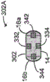
Fig. 3A and 3B are diagrams of exemplary sensor configurations for an ingestible device.
Fig. 4A and 4B are diagrams of another exemplary sensor configuration for an ingestible device.
Fig. 5A and 5B are diagrams of yet another exemplary sensor configuration for an ingestible device.
Fig. 6A and 6B are diagrams of yet another exemplary sensor configuration for an ingestible device.
Fig. 7A-7C show diagrams of the ingestible device of fig. 3A in exemplary operation.
Fig. 8A is a cross-sectional view of an exemplary embodiment of an ingestible device, illustrating regions for light that may be capable of being transmitted and detected during operation.
Fig. 8B and 8C are diagrams of the ingestible device of fig. 8A in an exemplary operation.
Fig. 9A is a flow chart of an exemplary embodiment of a method of operation for an ingestible device as described herein.
Fig. 9B is a flow diagram of an exemplary embodiment of a method of determining a quality of an environment external to an ingestible device as described herein.
Fig. 10A-10C are diagrammatic views of the ingestible device of fig. 3A during an exemplary transit through the Gastrointestinal (GI) tract of an individual.
Fig. 11A-11C are diagrammatic views of the ingestible device of fig. 4A during an exemplary transit through the GI tract of an individual.
Fig. 12A-12C are diagrams of the ingestible device of fig. 5A during an exemplary delivery through the GI tract of an individual.
Fig. 13A-13C are plots illustrating data collected during exemplary operation of the ingestible device of fig. 3A.
Fig. 14A is an exploded view of another exemplary embodiment of an ingestible device.
Fig. 14B is a cross-sectional view of the ingestible device of fig. 14A.
Fig. 15 is an exemplary block diagram of electrical components that may be used with the ingestible device of fig. 14A.
Fig. 16 is a flow chart of an exemplary embodiment of a method of operation for the ingestible device of fig. 14A.
Fig. 17A-17C are different views of an exemplary embodiment of a base station that may be used with an ingestible device.
Fig. 18A-18C are screenshots of an exemplary embodiment of a user interface for interacting with an ingestible device as described herein.
Fig. 19 is a diagram of another exemplary embodiment of an ingestible device.
Fig. 20 is a simplified top and side view of the apparatus of fig. 19.
Fig. 21 illustrates how light wavelengths may be used in some embodiments of devices that interact with different environments.
Fig. 22 shows the reflectance characteristics of different regions of the gastrointestinal tract when associated with the device.
Fig. 23 shows how different types of reflected light can be detected in different regions of the gastrointestinal tract.
Fig. 24 shows the measured reflectance in different regions of the gastrointestinal tract and the processing used to localize the device.
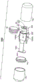
Fig. 25 is an external view of another embodiment of an ingestible device that may be used to sample the gastrointestinal tract or release a pharmaceutical agent.
Fig. 26 is an exploded view of the ingestible device of fig. 25.
Fig. 27 illustrates the main electrical sub-units corresponding to certain embodiments of the device.
FIG. 28 illustrates firmware corresponding to certain embodiments of a device.
FIG. 29 is a flow diagram that illustrates "fast loop" operation of the device that may allow for high speed processing at shorter intervals, according to some embodiments of the device.
Fig. 30A and 30B show a flow diagram illustrating a "slow-loop" operation of a device, according to some embodiments of the device.
FIG. 31 is a flow chart illustrating operational states of a device in an exemplary application according to some embodiments of the device.
Fig. 32 is a flow chart illustrating a cecum detection algorithm used in certain embodiments of the apparatus.
FIG. 33 is a flow chart illustrating a duodenal detection algorithm used in certain embodiments of the device.
Fig. 34 is data from an ingestible device administered to a patient during a trial.
FIG. 35 is a color chart showing the degree of change in reflected light detected by the device in thirteen different tests.
Detailed Description
Various systems, devices, and methods are described herein to provide examples for at least one embodiment of the claimed subject matter. The embodiments do not limit any of the claimed subject matter, and any of the claimed subject matter may cover systems, apparatus, and methods other than those described herein. It is possible that the claimed subject matter is not limited to systems, apparatuses, and methods having all of the features of any of the systems, apparatuses, and methods described herein or to features common to many or all of the systems, apparatuses, and methods described herein. It is intended that the systems, apparatus, or methods described herein are not embodiments of any claimed subject matter. Any subject matter disclosed in the systems, apparatus, and methods described herein and not claimed in this document can be subject to another protective device, e.g., successive patent applications, inventors, or owners with the intent to forego, disclaim, or dedicate any such subject matter disclosed herein with respect to the disclosure in this document.
It will be appreciated that for simplicity and clarity of illustration, where considered appropriate, reference numerals may be repeated among the figures to indicate corresponding or analogous elements. In addition, numerous specific details are set forth in order to provide a thorough understanding of the embodiments described herein. However, it will be understood by those skilled in the art that the embodiments described herein may be practiced without these specific details. In other instances, well-known methods, procedures, and components have not been described in detail so as not to obscure the embodiments described herein. Moreover, this description is not to be taken as limiting the scope of the embodiments described herein.
It should be noted that terms of degree such as "substantially", "about" and "approximately" as used herein mean a reasonable amount of deviation of the modified term such that the end result is not significantly changed. These terms of degree should be construed as including a deviation of the modified term if this deviation would not negate the meaning of the item it modifies.
Additionally, as used herein, the term "and/or" is intended to mean a logical or that may be doubled. That is, "X and/or Y" is intended to mean either X or Y or both, for example. As another example, "X, Y and/or Z" is intended to mean X or Y or Z or any combination thereof.
As used herein, the term "coupled" indicates that two elements may be coupled to each other directly or through one or more intermediate elements.
As used herein, the term "body" refers to the body of a patient, subject, or individual that receives an ingestible device. The patient or subject is typically a human or other animal.
Various embodiments described herein relate generally to an ingestible device for identifying one or more locations within the Gastrointestinal (GI) tract, and in certain embodiments, for collecting data and/or releasing substances, including pharmaceutical and therapeutic agents, at the identified locations. As used herein, the term "gastrointestinal tract" or "GI tract" refers to all parts of the organ system responsible for consuming and digesting food, absorbing nutrients, and discharging waste products. This includes orifices and organs, such as the mouth, throat, esophagus, stomach, small intestine, large intestine, rectum, anus, and the like, as well as the various flow passages and sphincters that connect the above components.
As used herein, the term "reflectivity" refers to a value derived from light emitted by the device, reflected back to the device, and received by a detector in or on the device. For example, in certain embodiments, this relates to light emitted by the device, wherein a portion of the light is reflected by a surface external to the device and the light is received by a detector located in or on the device.
As used herein, the term "illumination" relates to any electromagnetic emission. In certain embodiments, the illumination may be in the Infrared (IR), visible, and Ultraviolet (UV) ranges, and the illumination may have a majority of its power centered at a particular wavelength in the range of 100nm to 1000 nm. In certain embodiments, it may be advantageous to use illumination whose power is mostly limited to one of the infrared spectrum (750nm to 1000nm), the red spectrum (620nm to 750nm), the green spectrum (495nm to 570nm), the blue spectrum (450nm to 495nm), or the ultraviolet spectrum (100nm to 400 nm). In some embodiments, multiple illuminations with different wavelengths may be used.
Referring now to fig. 1A, shown therein is a view of an exemplary embodiment of an ingestible device 10, wherein a portion of a housing 12 of the ingestible device 10 has been removed. The ingestible device 10 may be used to independently and autonomously identify a location within a body, for example, a portion of the gastrointestinal tract. In certain embodiments, the ingestible device 10 may discern whether it is located in the stomach, in the small intestine, or in the large intestine. In certain embodiments, the ingestible device may also be capable of discerning what portion of the small intestine is located, e.g., the duodenum, jejunum, or ileum. The ingestible device 10 may generally have the shape of a capsule, like a conventional pill. Thus, the ingestible device 10 is shaped for easy ingestion and is familiar to health care practitioners and patients.
Unlike conventional pills, the ingestible device 10 is designed to withstand the chemical and mechanical environment of the GI tract (e.g., the effects of muscle contraction forces and high concentrations of hydrochloric acid in the stomach). However, unlike other devices (e.g., medical implants) that are intended to remain within the body of a patient, the ingestible device 10 may be designed to travel temporarily within the body. Accordingly, the normative rules governing the materials and manufacture of the ingestible device 10 may be less stringent than those for devices intended to remain within the body. However, because the ingestible device 10 enters the body, the materials used to manufacture the ingestible device 10 are typically selected to at least comply with standards for biocompatibility (e.g., ISO 10993). Furthermore, the components within the ingestible device 10 are free of any restricted and/or toxic metals and are lead-free in accordance with the directive 2002/95/EC of the european parliament, which directive 2002/95/EC is also known as the hazardous substances disable directive (RoHS).
A wide range of materials may be used to manufacture the ingestible device 10. Different materials may be used for each of the different components of the ingestible device 10. Examples of such materials include, but are not limited to, thermoplastics, fluoropolymers, elastomers, stainless steel, and glass that comply with ISO 10993 and USP class six specifications for biocompatibility; as well as any other suitable materials and combinations thereof . In some embodiments, these materials may also include: liquid silicone rubber material having properties such as using a durometer (e.g., manufactured by NuSil)TMManufactured MED-4942TM) The determined hardness rating of 10 to 90; soft biocompatible polymeric materials such as, but not limited to, polyvinyl chloride (PVC), Polyethersulfone (PES), Polyethylene (PE), Polyurethane (PU), or Polytetrafluoroethylene (PTFE); and a rigid polymeric material coated with a biocompatible material that is soft or flexible (e.g., a silicone polymer coated poly (methyl methacrylate) (PMMA) material). Using different materials for different components may enable some surfaces to be functionalized for interaction with proteins, antibodies, and other biomarkers. For example, may be used as a material for the movable components in the
 ingestible device 10 in order to reduce friction between these components. Other exemplary materials may include other materials commonly used in microfabrication, such as Polydimethylsiloxane (PDMS), borosilicate glass, and/or silicon. Although we may refer to the specific materials being used to construct the device for purposes of illustration, the listed materials are not intended to be limiting, and one skilled in the art can readily adapt the device for use with any number of different materials without affecting the overall operation or functionality of the device.
In certain embodiments, the housing 12 of the ingestible device 10 may be made of one type of plastic, for example, a photo-acrylic polymer material or an inert polycarbonate material. The housing 12 may also be formed using a material that can be sterilized by chemicals.
The housing 12 may be formed by coupling two enclosure portions together. For example, the two capsule parts may be mated and fused together by means of an adhesive material, such as a cyanoacrylate variant. In effect, the housing 12 protects the interior of the ingestible device 10 from its external environment, and also protects the external environment (e.g., the gastrointestinal tract) from components within the ingestible device 10.
Further, the ingestible device 10 may include one or more additional protective layers. Additional protection may protect the patient or individual against adverse effects caused by any structural issues associated with the enclosure 12 (e.g., the collapse of two enclosure portions in the enclosure 12 or the development of cracks). For example, the power source within the ingestible device 10 may be coated with an inert and flexible material (e.g., a thin layer of silicone polymer) such that only the electrical contacts on the power source are exposed. This additional protection of the power source may prevent the chemicals within the ingestible device 10 from infiltrating the patient's body.
In certain embodiments, the surface of the ingestible device 10 and the surface of different components in the ingestible device 10 may receive different treatments that vary depending on the intended use of the ingestible device 10. For example, the surface of ingestible device 10 may receive plasma activation for increasingly hydrophilic behavior. In another example, to minimize cross-contamination in the collected samples and/or substances for release, some storage components that may be in contact with these samples and/or substances may receive a hydrophilic treatment while some other components may receive a hydrophobic treatment.
The components of the ingestible device 10 may be too small and complex to manufacture with conventional tools (e.g., machine tools, hand milling machines, press drills, and the like), but too large for efficient construction using microfabrication techniques. Fabrication techniques that fall between conventional and microfabrication techniques may be used, including, but not limited to, 3D printing (e.g., 3D multi-nozzle modeling (MJM)), mechanical computer-aided design (CAD). SolidWorksTMAnd/or AlibrTMIs an example of CAD software that may be used to design some of the components of the ingestible device 10, although any suitable CAD software may be used.
In certain embodiments, the components of the ingestible device 10 may be manufactured using different conventional manufacturing techniques, such as injection molding, Computer Numerical Control (CNC) machining, and by using a multi-axial lathe. For example, the housing 12 of the ingestible device 10 may be fabricated from CNC machined polycarbonate material, and the storage component may be fabricated by applying a biocompatible material, such as a silicone polymer, to a 3D printed mold or casting.
The silicone polymer may provide certain advantages to the manufacturing process of the ingestible device 10. For example, components formed using silicone polymer materials in the ingestible device 10 may be manufactured using conventional methods, e.g., molding techniques. Silicone polymer materials are also flexible materials. Accordingly, components of the ingestible device 10 formed from silicone polymer materials may accommodate a range of design variations during the manufacturing stage and may also be adapted for compression fitting.
Still referring to fig. 1A, an ingestible device 10 is shown according to an exemplary embodiment. The ingestible device 10 includes a housing 12 for providing an enclosure for various electronic and mechanical components. The housing 12 includes a first end portion 16a, a second end portion 16b, and a radial wall 14 extending from the first end portion 16a to the second end portion 16 b.
The radial wall 14 may be formed from one or more components. In the example of fig. 1A, the radial wall includes a first wall portion 14a, a second wall portion 14b, and a connecting wall portion 14c for connecting the first wall portion 14a with the second wall portion 14 b. Other configurations of the radial wall 14 may be used depending on the application of the ingestible device 10.
Referring now to fig. 1B, shown therein is an exploded view of the components of ingestible device 10 in one exemplary embodiment. Enclosed within the first wall portion 14a, as shown in fig. 1A and 1B, are a Printed Circuit Board (PCB)30, a battery 18, sensing sub-units 32, 42 and a communication sub-unit 120. Various components within the ingestible device 10 are described with reference to fig. 2A-2E.
Fig. 2A is a block diagram 100 of an exemplary embodiment of electrical components that may be used with the ingestible device 10. As shown in block diagram 100, ingestible device 10 may include a microcontroller 110, a communication subunit 120, a sensing subunit 130, a power supply 160, and a memory subunit 140. At least some of the electronic components may be embedded on the PCB 30.
In certain embodiments, the microcontroller 110 includes programming, controlAnd memory circuits for holding and executing firmware or software and coordinating all functions of the ingestible device 10, as well as other peripherals embedded on the PCB 30. For example, the microcontroller 110 may be implemented using a 32-bit microcontroller, e.g., from STMicroelectronics TMSTM32 series, but any suitable microcontroller may be used.
The microcontroller 110 provided in fig. 2A may include a general purpose input/output (I/O) interface 112, an SPI or universal asynchronous receiver/transmitter (UART) interface 114, and an analog-to-digital converter (a/D converter) 116. The microcontroller 110 may consider the a/D converter 116 as a peripheral device.
The general purpose I/O interface 112 includes a fixed number of general purpose input/output pins (GPIOs). These GPIOs may be grouped into sets of two-pin or three-pin pins for implementing various communication protocols, such as single-wire interfaces (SWIs), two-wire interfaces (e.g., inter-integrated circuits or I-pins)2C) And/or a Serial Peripheral Interface (SPI). Sets of GPIOs delegated to these communication protocols may be used as buses for connecting the microcontroller 110 with one or more peripheral devices.
Using any of the communication protocols listed above, or using any other suitable communication protocol, the microcontroller 110 may send a series of requests to the address associated with a particular GPIO group for detecting which, if any, peripherals are present on the bus. If any of the peripherals are present on the bus, the present peripheral returns an acknowledge signal to the microcontroller 110 within a specified timeframe. If no response is received within the specified timeframe, the peripheral is considered absent.
The a/D converter 116 may be coupled with any one of the sensors in the sensing sub-unit 130. In certain embodiments, the ingestible device 10 may communicate by receiving and/or transmitting infrared light, in which case an Infrared (IR) sensitive phototransistor and resistor coupled to the a/D converter 116 are included in the communication subunit 120. Additionally, in certain embodiments, the ingestible device 10 may include an Infrared (IR) Light Emitting Diode (LED) coupled to the microcontroller 110 to communicate signals to the outside of the device.
In some embodiments, the communication sub-unit 120 may receive operating instructions from an external device, such as a base station (e.g., an infrared transmitter and/or receiver on a base station (dock)). The base station may be used to initially program the ingestible device 10 with operating instructions and/or communicate with the ingestible device 10 in real time during operation or after retrieving the ingestible device 10 from a body. In some embodiments, the communication sub-unit 120 does not receive any operating instructions from an external device, and instead the ingestible device 10 operates autonomously within the body.
In some embodiments, the communication sub-unit 120 may include an optical encoder 20, such as an infrared transmitter and receiver. The IR transmitter and receiver may be configured to operate using modulated infrared light, i.e. light in the wavelength range of the phases 850nm to 930 nm. Further, an IR receiver may be included in the ingestible device 10 for receiving programming instructions from an IR transmitter at a base station, and an IR transmitter may be included in the ingestible device 10 for transmitting data to the IR receiver at the base station. Accordingly, two-way IR communication can be set between the ingestible device 10 and the base station. It will be appreciated that other types of optical encoders or communication sub-units may be used in some embodiments; for example, some communication sub-units may utilize bluetooth, Radio Frequency (RF) communication, near field communication, and the like, rather than (or in addition to) optical signals.
The sensing sub-unit 130 may include various sensors to acquire in-vivo information while the ingestible device 10 is being transported in the body. Various sensors, such as the radial sensor 32 and the axial sensor 42, may be provided at different locations of the ingestible device 10 to help identify where the ingestible device 10 may be located within the body. In certain embodiments, the data provided by the sensors 32, 42 may be used to trigger operation of the ingestible device 10. For example, in certain embodiments, the ingestible device 10 may be adapted to include a sampling chamber capable of taking a sample from the gastrointestinal tract from a region surrounding the device, and the data provided by the sensors 32, 42 may trigger the device to take the sample. Each sensor 32, 42 may include an illuminator 32i and 42i and a detector 32d and 42 d. The sensors 32, 42 are further described with reference to fig. 3A-8C. As another example, in certain embodiments, the ingestible device 10 may be adapted to deliver substances including medicaments and therapeutic agents, and the data provided by the sensors 32, 34 may trigger the device to deliver the substances.
The memory sub-unit 140 may be provided with a memory storage unit 142, such as a flash memory, an EEPROM and the like. The memory sub-unit 140 may be used to store instructions received from the base station and to store various other operational data, such as transportation data and sensor data collected by the sensing sub-unit 130. In certain embodiments, microcontroller 110 may be operative to execute instructions stored at memory sub-unit 140 that may be related to operating other components of ingestible device 10, such as sensing sub-unit 130, communication sub-unit 120, and power supply 160.
In certain embodiments, the power source 160 may include one or more batteries 18 formed of different chemistries, such as lithium polymer, lithium carbon, silver oxide, alkaline, and the like. This may help accommodate different power requirements of various components in the ingestible device 10. In certain embodiments, power source 160 may include a silver oxide cell for supplying power to various components in ingestible device 10. The battery cell supplying power to the power supply 160 may operate at 1.55V. For example, the method of Renata may be usedTMSilver oxide button cell type batteries were manufactured because button cell type batteries had discharge characteristics suitable for the operation of the ingestible device 10. In some embodiments, other types of cells may be used.
In certain embodiments, one or more battery cells can be included for power supply 160. For example, multiple button cells may be used to provide higher voltages for operation of the ingestible device. It may also be possible for the power supply 160 to include one or more different types of cells.
Also, the power supply 160 may be divided into one or more cell groups to prevent temporary interruptions or variations at the power supply 160 from affecting the overall operation of the ingestible device 10. For example, the exemplary power supply 160 may include three cells, and each cell may be operable to provide 1.55 volts. In one exemplary embodiment, three cells may be arranged as a cell group operable to provide 4.65 volts as full voltage. The voltage regulator may control the voltage provided by the cell stack. The voltage regulator may operate to provide a regulated voltage, e.g., 3.3 volts, to the microcontroller 110 while simultaneously operating to provide a full voltage to the sensing subunit 130. In another exemplary embodiment, three cells may be provided as two different sets of cells, a first set of cells including two cells and a second set of cells including one cell. Thus, the first monomer set may provide 3.1 volts, while the second monomer set may provide 1.55 volts. The first cell set may be operable to provide 3.1 volts to the microcontroller 110 to prevent voltage variations. The first cell set and the second cell set may then combine to provide 4.65 volts to the sensing subunit 130.
In certain embodiments, the power supply 160 may include a magnetic switch 162 for operating as an 'ON'/'OFF' mechanism for the ingestible device 10. When exposed to a stronger magnetic field, the magnetic switch 162 may be maintained in an 'OFF' position in which the ingestible device 10 is not activated. The stronger magnetic field may effectively stop the current in the ingestible device 10, causing an open circuit to occur. This may prevent, for example, the ingestible device 10 from consuming energy and discharging the battery 18 prior to administration to a patient. However, when the magnetic switch 162 is no longer exposed to a strong magnetic field, the magnetic switch 162 may be switched to the 'ON' position to activate the ingestible device 10. The current may then flow through an electrical pathway (e.g., a pathway on PCB 30) in the ingestible device 10.
In certain embodiments, from MEDERTMAn electronic MK24 magnetic loop inductor may be used as the magnetic switch 162, but any suitable magnetic switch may be used. For example, in certain embodiments, the magnetic switch 162 may be magnetically actuated, normally closed, single pole, single throw(SPST to NC) switch. In certain embodiments, for example, by MEMSCAPTMA fabricated micro-electromechanical system (MEMS) magnetic switch may be used as the magnetic switch 162. In some embodiments, the magnetic switch 162 may be a hall effect sensor.
In some embodiments, power supply 160 may be removed from ingestible device 10 to be recharged by a charging circuit external to ingestible device 10. In some embodiments, when the charging circuit is included on the PCB 30, the power supply 160 may be recharged while in the ingestible device 10; for example, by providing circuitry that allows the ingestible device 10 to be inductively coupled to a base station and wirelessly charged.
Fig. 2B is an exemplary circuit design 102 of certain electrical components of the ingestible device 10. It will be appreciated that circuit design 102 is merely an example and that other configurations and designs may similarly be used. FIG. 2C is an exemplary circuit design 104 of sensing subcell 130.
As described above, some of the electronic components may be embedded on the PCB 30. Fig. 2D and 2E show a top view 106t and a bottom view 106b, respectively, of the circuit design of the flexible PCB 30.
The PCB 30 may be composed of a flexible printed circuit. The flexible printed circuit may maximize space utilization within the ingestible device 10 by being able to more easily conform to size constraints of the ingestible device 10. The increased flexibility allows the PCB or certain components of the PCB to be more twisted, bent and shaped, ultimately resulting in smaller pills that are more robust to vibratory or torsional forces.
The PCB 30 in this example includes a communication sub-unit 120, a microcontroller 110, a sensing sub-unit 130, and other peripheral components that will be described below. The electronic components located on the PCB 30 are electrically coupled to other components by one or more electronic signal paths, traces or tracks.
The flexible PCB 30 may be manufactured using a combination of flexible plastic material and rigid material, for example, woven fiberglass cloth material, or any other suitable material. Thus, the resulting flexible PCB 30 may exhibit both a pliable mass and a rigid mass. The pliable quality of the flexible PCB 30 enables the electronic components located on the flexible PCB 30 to conform to the size constraints of the ingestible device 10. In particular, as generally shown in fig. 1A, the flexible PCB 30 may be inserted into the first wall portion 14 a. At the same time, the rigid mass of the flexible PCB 30 can stiffen areas that may be susceptible to higher physical stress levels. For example, in some embodiments, the contact terminals (e.g., 218b) used to connect the flexible PCB 30 to the power supply 160 may have added reinforcement.
As shown in fig. 2D and 2E, the flexible PCB 30 includes one or more separate but connected segments. For example, the flexible PCB 30 may include a main PCB section 202 and one or more smaller PCB sections 204, e.g., smaller PCB sections 204a and 204 b. The smaller PCB section 204 may be directly or indirectly connected to the main PCB section 202. The main PCB section 202 may be rolled into a generally cylindrical shape to conform to the structural dimensions of the ingestible device 10.
As shown in fig. 1B, the smaller PCB segments 204a and 204B may be folded into one or more overlapping layers and fit into the ingestible device 10. In some embodiments, the smaller PCB segments 204a and 204b may be layered around the battery 18. It will be appreciated that the flexible PCB30 may have different configurations, e.g., different shapes and sizes and/or different numbers of segments.
The electronic components may be located on either the main PCB section 202 or the smaller PCB sections 204a and 204 b. For example, as shown in fig. 2D and 2E, the main PCB section 202 may include the microcontroller 110, the magnetic switch 162, and the radial sensor 32. The smaller PCB section 204a may include the optical encoder 20 and the axial sensor 42. The smaller PCB segments 204a and 204b may also include respective power contact terminals 218a and 218b for engaging the battery 18. In some embodiments, other arrangements of these components are possible on the flexible PCB 30.
Referring again to fig. 1A, the first end portion 16a generally encloses components at the first wall portion 14a of the ingestible device 10. The first end portion 16a and the first wall portion 14a may be made of optically and radio translucent or transparent materials. This type of material allows for transmission and reception of light, for example, by the sensors 32, 42. In certain embodiments, the first end portion 16a and the first wall portion 14a may be made of plastic.
In some embodiments, sensing sub-unit 130 may be oriented or disposed relative to housing 12 so as to reduce internal reflections caused by the output of sensing sub-unit 130. For example, sensing sub-unit 130 may be oriented at an angle relative to the circumference of housing 12 so that minimal internal reflections are caused by housing 12 when the output of sensing sub-unit 130 reaches housing 12. In some embodiments, a transition medium, such as a quantity of oily substance, may be disposed between the sensing sub-unit 130 and the housing 12 so that the refractive indices of the transition medium and the sensing sub-unit 130 may match the refractive index of the housing 12, reducing reflections and scattering. In some embodiments, the illuminator and the detector of each sensor (e.g., illuminator 32i and detector 32d of sensor 32) may be physically separated around the circumference of the device. For example, in the embodiments discussed in fig. 8A-8C, 19, and 20, the separate illuminator 32i and detector 32d may also reduce internal reflections.
In certain embodiments, the sensing sub-unit 130 includes an axial sensing sub-unit 42 and a radial sensing sub-unit 32 at different locations of the ingestible device 10 to facilitate estimating the location of the ingestible device 10 within the body. The ingestible devices 10, 300 move within the body at variable speeds. Within the gastrointestinal tract, for example, the varying size, shape, and environment of different gastrointestinal tract segments can make location identification difficult.
Referring now to fig. 3A and 3B, shown therein are diagrams of an exemplary ingestible device 300. Fig. 3A and 3B generally illustrate an exemplary configuration of the sensors 332, 342 relative to certain components of the housing 12. Fig. 3A is a cross-sectional view 300A of ingestible device 300, and fig. 3B is a three-dimensional side view 300B of ingestible device 300.
An axial sensing sub-unit 42 is located proximal to at least one of the first and second end portions 16a, 16 b. As shown in fig. 3A, the axial sensor 342 is located proximal to the first end portion 16 a. It will be appreciated that, depending on the configuration of ingestible device 300, axial sensor 342 may instead be located proximal to second end portion 16 b. The radial sensing sub-unit 32 is generally located proximal to the radial wall 14. For example, as shown in fig. 3A and 3B, the radial sensor 332 is located proximal to a portion of the radial wall 14.
An exemplary conveyance of ingestible device 300 is shown in fig. 10A-10C. The transport of the ingestible device 300 through the stomach 452, small intestine 454, and then large intestine 456 is shown generally at 450A, 450B, and 450C, respectively. The movement of the ingestible device 300 substantially changes depending on its location. As shown in fig. 10A, the stomach 452 is a large, open, and cavernous organ, and thus the ingestible device 300 may have a large range of motion. On the other hand, as shown in fig. 10B, the small intestine 454 has a tubular structure, and the ingestible device 300 is generally limited to longitudinal motion. Similar to the stomach 452, the large intestine 456 is a larger open structure, and the ingestible device 300 may have a larger range of motion, as compared to being transported through the small intestine 454. By providing the axial sensing sub-unit 42 and the radial sensing sub-unit 32, different degrees and types of reflectivity data may be obtained depending on the shape and/or size of the transport location. The varying reflectivity data is further illustrated in fig. 13A, 13B, and 13C.
In certain embodiments, each axial sensor 342 and each radial sensor 332 may include an illuminator for directing illumination toward the environment external to the housing 12 and a detector for detecting reflectance caused by illumination from the environment. Illumination may include any electromagnetic emission in the Infrared (IR), visible, and Ultraviolet (UV) ranges. Exemplary operation of the sensors 342, 332 is described below with reference to fig. 7A-7C.
Fig. 7A-7C illustrate the operation of the axial sensor 342 and the radial sensor 332 in different environments. In each of fig. 7A-7C, the illuminators and detectors of sensors 332 and 342 are shown for ingestible device 300. The axial sensor 342 includes an axial illuminator 342i for transmitting axial illumination to the external environment and an axial detector 342d for detecting axial reflectance from the external environment (i.e., outside the ingestible device 300). The axial reflectivity may be caused by different illumination depending on the external environment.
Similarly, the radial sensor 332 comprises a radial illuminator 332i for transmitting radial illumination to the external environment and a radial detector 332d for detecting radial reflectivity from the external environment. Like the axial reflectivity, the radial reflectivity may be caused by different illumination depending on the external environment. For example, in certain embodiments, there may be multiple radial illuminations, and the detected radial reflectivity may be caused by multiple radial illuminations reflected from the external environment and scattered in multiple directions. As shown in fig. 7A-7C, the radial illuminator 332i is positioned such that the resulting radial illumination is in a different direction than the axial illumination produced by the axial illuminator 342 i. In certain embodiments, the radial illumination is substantially perpendicular to the axial illumination.
Fig. 7A illustrates the transport of ingestible device 300 through opaque liquid 410. The opaque liquid 410 contacts the radial wall 14 of the ingestible device 300 as it is transported through the gastrointestinal tract under certain conditions, similar to the manner in which an opaque fluid within the large intestine (e.g., large intestine 456 of fig. 10C) may contact the ingestible device 300. Thus, the radial illumination transmitted by the radial illuminator 332i is almost entirely internally reflected and detected by the radial detector 332d, causing a greater reflectivity to be being detected. In this example, the axial detector 342d does not detect any reflectivity because no material or tissue is disposed in front of the axial illuminator 342 i.
Fig. 7B illustrates the transport of ingestible device 300 in proximity to tissue 412. The radial illumination transmitted by the radial illuminator 332i is partially reflected (and partially absorbed by the tissue 412) and detected by the radial detector 332d, similar to the manner in which the radial illumination may interact with tissue of a small intestine (e.g., the small intestine 454 of fig. 10B) or other organ under conditions. Similar to fig. 7A, in this example, the axial detector 342d also does not detect any reflectivity because no material or tissue is disposed within the range of the axial detector 342 d. The amount of illumination reflected and absorbed by the tissue 412 may depend on the wavelength of the illumination. For example, red tissue may reflect illumination having wavelengths in the red spectrum (i.e., 620nm to 750nm) well, causing the ingestible device 300 to be detecting higher reflectivities. In contrast, illumination having wavelengths in the green spectrum (495nm to 570nm) or the blue spectrum (450nm to 495nm) may be absorbed by tissue, causing the ingestible device 300 to be detecting a lower reflectance. In certain embodiments, multiple radial or axial illuminations with different respective wavelengths may be used to help identify the location of ingestible device 300 within the gastrointestinal tract, given that different organs and portions of the gastrointestinal tract have different reflective characteristics.
Fig. 7C illustrates the transport of ingestible device 300 through a transparent liquid with particles 414. This type of environment may be similar to the environment found in the stomach (e.g., stomach 452 of fig. 10A) under certain conditions. As shown, the axial illumination and the radial illumination are reflected by the particles 414 a-414 d within the range of the respective axial illuminator 342i and radial illuminator 332 i. It is also possible for some of the illumination to reflect from one particle to another, such as from particle 414c to particle 414 b. The reflectivity detected by each of the axial detector 342d and the radial detector 332d may not be limited to the illumination produced by the respective axial illuminator 342i and radial illuminator 332 i. The reflectivity caused by radial illumination can be detected for the axial detector 342 d. Similarly, the reflectivity caused by axial illumination can be detected for the radial detector 332 d. In certain embodiments, this effect can be reduced by having the axial sensor 342 and the radial sensor 332 use illumination having two different wavelengths. For example, if the radial sensor 332 has an illuminator 332i and a detector 332d that transmit and detect wavelengths in the red spectrum and the axial sensor 342 has an illuminator 342i and a detector 342d that transmit and detect wavelengths in the infrared spectrum, the effect of the axial illuminator 342i on the radial detector 332d is reduced.
Various embodiments of the sensors 32, 42 are described below with reference to fig. 4A-8C.
Referring now to fig. 4A and 4B, shown therein are diagrams of another exemplary ingestible device 302. Fig. 4A is a cross-sectional view 302A of the ingestible device 302, and fig. 4B is a three-dimensional side view 302B of the ingestible device 302. Ingestible device 302 includes an axial sensing sub-unit 42 having two axial sensors 342 and 344 and a radial sensing sub-unit 32 having two radial sensors 332 and 334, 42 and 32.
As described with reference to fig. 3A and 3B, the axial sensor 342, or first axial sensor, is located proximal to the first end portion 16 a. The axial sensor 344 or second axial sensor is located proximal to the second end portion 16 b. As shown in fig. 4A and 4B, the first and second axial sensors 342 and 344 are substantially opposite each other relative to the housing 12. Thus, the first axial illumination produced by the first axial sensor 342 will be in a substantially opposite axial direction from the second axial illumination produced by the second axial sensor 344.
The radial sensor 332 or first radial sensor of the ingestible device 302 is located proximal to the first wall portion 14 of the radial wall, while the radial sensor 334 or second radial sensor is located proximal to the second wall portion. As shown in fig. 4A and 4B, the first wall portion is spaced about 180 degrees from the second wall portion along the circumference of the radial wall 14. The first and second radial illuminations generated by the respective first and second radial sensors 332, 334 are along different radial directions. As a result, the first radial illumination and the second radial illumination are transmitted in substantially opposite directions.
Generally, in embodiments where the radial sensing sub-unit 32 is comprised of two or more radial sensors 332, 334, the radial sensors 332 and 334 may be spaced at least 60 degrees apart along the circumference of the radial wall 14 so as to cause the resulting first and second radial illuminations to be in substantially different radial directions from one another. Also, the separation between the radial sensor 332 and the radial sensor 334 may help to minimize internal reflections.
When more sensors are provided in the ingestible devices 10, 300, 302, more reflectance data will become available. As described with reference to fig. 10A-12C, the reflectance data may increase the accuracy with which the location of the ingestible device 10, 300, 302 within the body may be identified.
Referring now to fig. 5A and 5B, shown therein are diagrams of yet another exemplary ingestible device 304. Fig. 5A is a cross-sectional view 304A of the ingestible device 304, and fig. 5B is a three-dimensional side view 304B of the ingestible device 304. Similar to ingestible device 300, ingestible device 304 includes axial sensing sub-unit 42 having one axial sensor 342. However, unlike ingestible devices 300 and 302, radial sensing sub-unit 32 of ingestible device 304 includes four radial sensors 332, 334, 336, and 338.
As described above, the radial sensors 332, 334, 336 and 338 are generally disposed such that they are spaced at least 60 degrees apart along the circumference of the radial wall 14. In the ingestible device 304, the radial sensors 332, 334, 336, and 338 may be positioned substantially equidistant from each other along the circumference of the radial wall 14. Note that, similar to ingestible device 300, but unlike ingestible device 302, ingestible device 304 has a single axial sensor 342 near first end portion 16 a. In certain embodiments, the ingestible device (e.g., ingestible devices 300, 304) may have a sampling chamber located proximal to the second end portion 16b that is substantially opposite the location of the axial sensor 342. This embodiment is shown in fig. 14A, 14B and 25. In certain embodiments, an ingestible device (e.g., ingestible devices 700, 2500) may have a chamber for storing a substance that is delivered to the gastrointestinal tract. These embodiments are shown in fig. 14A to 14B and fig. 25.
Referring now to fig. 6A and 6B, shown therein are diagrams of yet another exemplary ingestible device 306. Fig. 6A is a cross-sectional view 306A of the ingestible device 306, and fig. 6B is a three-dimensional side view 306B of the ingestible device 306. The ingestible device 306 includes an axial sensing sub-unit 42 having two axial sensors 342 and 344 similar to the ingestible device 302 of fig. 4A and 4B and a radial sensing sub-unit 32 having four radial sensors 332, 334, 336, and 338 similar to the ingestible device 304 of fig. 5A and 5B.
Referring now to fig. 8A, shown therein is a cross-sectional view of yet another exemplary embodiment of an ingestible device 308. For ease of illustration, the axial sensing sub-unit 42 of the ingestible device 308 is not shown in fig. 8A. The radial sensing subunit 32 includes three radial sensors 352, 354, and 356. In the ingestible device 308, the illuminator and the detector of each of the respective radial sensors 352, 354, and 356 are separated from each other by about 60 degrees. With this configuration, each of the radial illuminators 352i, 354i, and 356i has a respective illumination area 362i, 364i, and 366i of about 120 degrees relative to the circumference of the radial wall 14. Similarly, each of the radial detectors 352d, 354d, and 356d has a respective detection zone 362d, 364d, and 366d that is about 120 degrees relative to the circumference of the radial wall 14.
The separation between the radial sensors 352, 354, and 356 may help to minimize internal reflections. For example, when the radial sensors 352, 354, and 356 in the ingestible device 308 are separated from each other by approximately 60 degrees, the radial sensors 352, 354, and 356 are approximately equidistant from each other along the circumference of the ingestible device 308 and are also separated from each other by a maximum distance. As a result, internal reflections at the interface of the housing 12 may be minimized.
Fig. 8B and 8C illustrate exemplary operation of radial sensors 352, 354, and 356 in different environments. Fig. 8B shows the ingestible device 308 being transported through the small intestine 454 at 402A. Due to the tubular structure of the small intestine 454, the wall of the small intestine 454 closely surrounds the ingestible device 308. Fig. 8C shows the ingestible device 308 being transported through a larger space, such as the stomach 452, at 402B. By physically separating the radial illuminators 352i, 354i and 356i and the radial detectors 352d, 354d and 356d in the manner shown in fig. 8A, a more variable reflectivity can be detected as shown in fig. 8B and 8C.
For ingestible devices 10, 300, 302, 304, 306, and 308 described herein, the axial sensing sub-unit 42 may include one or more axial sensors. At least one of the axial sensors may have an infrared light emitting diode (IR-LED) as an illuminator and a detector sensitive to illumination in the infrared spectrum. The radial sensing sub-unit 32 may also include one or more radial sensors. In some embodiments, the radial sensor may comprise a yellow-green LED emitting light having a wavelength of about 571nm as the illuminator. In certain embodiments, the radial sensor may include a green LED emitting light having a wavelength of about 517nm and a red LED emitting light having a wavelength of about 632 nm. In some embodiments, the radial sensor may include an RGB LED package capable of emitting illumination at a plurality of different wavelengths.
When the radial sensor comprises an RGB LED package, the ingestible device 10 may emit different wavelengths sequentially. Some tissues and fluids may have different absorbencies for different wavelengths of illumination. With RGB LEDs, a larger range of reflectance data can be collected and analyzed.
For example, an RGB LED package may transmit red illumination having a wavelength at about 632nm and detect the reflectance caused by the red illumination. The RGB LED package may then transmit green illumination having a wavelength at about 518nm and detect the reflectance caused by the green illumination. The RGB LED package may then transmit blue illumination having a wavelength at about 465nm and detect the reflectance caused by the blue illumination. To determine the corresponding position of the ingestible device 10 based on the reflectance data acquired by the RGB LED package at various frequencies, the microcontroller 110 and/or an external processing module may compare each series of reflectance data to one another. It may be possible that one or more portions of the series of reflectance data at a particular wavelength may be excluded from consideration. Embodiments that determine the location of a device by comparing reflectance data from different wavelengths are shown in fig. 19-24.
The detected reflectivities from each of the different types of illumination may be stored in the memory sub-unit 140 for subsequent processing by the microcontroller 110. Additionally, in certain embodiments, the processing may be performed by an external processing module.
In certain embodiments, the axial sensor and the radial sensor may comprise collimated light sources. The collimated light source may be oriented to reflect light so as to maximize reflectivity from certain external environments, such as a circular shaped anatomical structure. For example, illumination may be provided by a collimated light source, which may be provided using an LED package (binning) or a supplemental lens, or illumination may be provided by a combination of collimated and non-collimated light sources.
In certain embodiments, after the sensing sub-unit 130 of the various ingestible devices 10, 300, 302, 304, and 306 described herein collects reflectance data, the communication sub-unit 120 may transmit the detected radial and axial reflectance data to an external processing module. In certain embodiments, a device processing module (not shown) is provided in the ingestible devices 10, 300, 302, 304, and 306, and the reflectance data may be provided to the device processing module for processing. The processing module, whichever it is, may then identify the location of the respective ingestible devices 10, 300, 302, 304, and 306 according to the methods described herein. In some embodiments, the microcontroller 110 may function as a processing module.
As described above, the processing module may be the microcontroller 110 disposed on the PCB 30 or an external processing module. When the detected data is provided to the external processing module for analysis, the communication sub-unit 120 may store the detected data in the memory sub-unit 140 and then provide the detected data to the external processing module (e.g., after the ingestible devices 10, 300, 302, 304, and 306 are removed from the body), or the communication sub-unit 120 may provide the detected data in real time using a wireless communication component, e.g., a Radio Frequency (RF) transmitter. It should be noted, however, that some or all of the processing for determining the location of the device may be performed within the device by the microcontroller 110.
As described above, the reflectance data collected by the sensing sub-unit 130 may be used to infer the in-vivo location of the ingestible device 10. As described with reference to fig. 9-12C, the axial reflectance data and the radial reflectance data may be used to identify different organs and/or delivery points. For example, the levels of axial reflectivity and radial reflectivity may indicate the type of external environment.
Also, different materials may have different refractive indices, and thus the resulting absorption properties may vary. For example, fluids tend to have a lower refractive index than tissue. Depending on the type of organ, different materials may be present. For example, in the stomach, certain liquids and food particles may be present. On the other hand, in the small intestine, there is limited liquid, but there may be bubbles or gas. Based on the reflectivity data, the processing module may determine some characteristic of the environment in which the reflectivity data is detected.
Reference is now made to fig. 9A, which is a flowchart of an exemplary method 500 or another embodiment described herein for operation of ingestible devices 10, 300, 302, 304, 306, and 308. To illustrate the operation of the ingestible devices 10, 300, 302, 304, 306, and 308, reference is also made to fig. 10A-12C.
At step 510, any of the ingestible devices described herein, e.g., 10, 300, 302, 304, 306, and 308, may be set up. As described above, sensing sub-unit 130 may transmit illumination and collect reflectance data caused by the illumination interacting with the external environment.
At step 520, the sensing sub-unit 130 is operated to acquire a reflectivity data series as the ingestible devices 10, 300, 302, 304, 306, and 308 are transported through the body.
The reflectivity data series may include an axial reflectivity data series and a radial reflectivity data series. Each of the series of axial reflectivity data and the series of radial reflectivity data may include one or more reflectivity values indicative of the respective axial reflectivity and radial reflectivity detected by the sensing sub-unit 130 during at least a portion of the transport. In some embodiments, the processing module may receive the reflectivity data series in real time and operate to identify the in-vivo location in real time, and thus the processing module will only be able to utilize portions of the reflectivity data series. In certain embodiments, the processing module may receive the reflectance data after the ingestible devices 10, 300, 302, 304, 306, and 308 have left the body, and thus a complete series of reflectance data is available to the processing module.
Fig. 10A-10C generally illustrate transport of the ingestible device 300 through the stomach 452, through the small intestine 454, and then through the large intestine 456.
As shown at 450A, the stomach 452 is a larger space. Thus, ingestible device 300 may move along all axes. The motion of the ingestible device 300 may cause higher deviations in the reflectance data series. Moreover, the contents of the stomach 452 may include not only relatively clear liquid, but also particulates if an individual has not fasted or not sufficiently fasted prior to ingesting the ingestible device 300. Thus, some reflectivity data may be caused by the presence of the particles.
In the example of fig. 10A, the ingestible device 300 rotates several times as it is transported through the stomach 452. It will be understood that the path and orientation of ingestible device 300 is merely an example, and that other paths and orientations are possible. At position "I", both the axial sensor 342 and the radial sensor 332 face the wall of the stomach 452, but at different distances. The resulting reflectivity detected by the axial sensor 342 and the radial sensor 332 will likely change due to the different absorption caused by the different distances. Axial and radial reflectivity will likely result from interaction of the walls of the stomach 452 with the particles 414 within the stomach 452. It is also possible for the axial sensor 342 to detect the reflectivity resulting from the illumination produced by the radial sensor 332, and vice versa. The axial and radial reflectance values may be altered by the contents that would be present in the stomach 452. If the individual has sufficiently fasted, there may be a smaller amount of particles 414 in the stomach 452, and therefore, the resulting reflectance value may be lower.
At position "II", the axial sensor 342 faces the wall of the stomach 452 more closely than at position "I". The axial sensor 342 will detect a higher reflectance value from the wall of the stomach due to the close proximity to the wall of the stomach 452. The radial sensor 332 does not directly face the wall of the stomach 452. However, because the radial sensor 332 is exposed to the contents of the stomach 452, the radial sensor 332 will detect the reflectance caused by any particles 414 present within the stomach 452.
The axial and radial reflectivities detected by the axial sensor 342 and the radial sensor 332 at location "III" are similar to the reflectivities detected at location "I". The values may vary due to the contents of the stomach 452 being absorbed by different amounts.
However, at location "IV", the ingestible device 300 begins to be transported through the pylorus, which is a significantly narrower structure compared to the stomach 452. As shown in fig. 10A, the axial sensor 342 faces the small intestine 454, and thus will continue to detect reflectance caused by the contents that may be present in the small intestine 454. However, the radial sensor 332 is in close contact with the pyloric wall and will detect higher reflectance values caused by illumination of the pyloric wall. Due to the close contact between the pyloric wall and the radial sensor 332, the axial sensor 342 will detect very little, if any, reflectivity caused by the illumination transmitted by the radial sensor 332.
Fig. 10B illustrates transport of the ingestible device 300 through the small intestine 454. As described above, the small intestine 454 has a tubular structure, and thus, the ingestible device 300 is limited to longitudinal and rotational movement along its longitudinal axis. Also, the small intestine 454 typically includes limited liquid, but may include a wet mucus layer and bubbles or gas.
The axial and radial reflectivities detected by ingestible device 300 at locations "V" and "VI" are similar to the reflectivities detected at location "IV". The axial sensor 342 faces one end of the small intestine 454 and will detect the reflectivity caused by the particles 414 (if present) or bends in the small intestine 454. However, the radial sensor 332 is in close contact with the wall of the small intestine 454 and will detect a higher reflectance value caused by illumination of the wall of the small intestine 454. Due to the close contact between the wall of the small intestine 454 and the radial sensor 332, the axial sensor 342 will detect very little, if any, reflectivity caused by the illumination transmitted by the radial sensor 332.
After the ingestible device 300 is transported through the small intestine 454, the ingestible device 300 enters the large intestine 456. Generally, the large intestine 456 is characterized by having an opaque brown content due to the presence of fecal matter. Opaque contents may include liquids and/or solids. Depending on the type of illumination being generated, the detected reflectivities at locations "VII", "VIII" and "IX" will change. For example, it can be that when the illumination is in the visible spectrum (as shown in fig. 7A for the radial sensor 332), the detected reflectivities at locations "VII", "VIII", and "IX" can be primarily internal reflectivities. When the illumination is IR illumination or green illumination, the detected reflectivities at positions "VII", "VIII" and "IX" may be associated with rather high values due to the content of the brown color.
The transport of the ingestible device 302 through the stomach 452, through the small intestine 454, and then through the large intestine 456 is described with reference to fig. 11A-11C. As shown in fig. 4A and 4B, ingestible device 302 includes two radial sensors 332 and 334 and two axial sensors 342 and 344. Thus, additional reflectance values may be detected.
Referring first to fig. 11A, the reflectance values detected by sensors 332, 334, 342, and 344 in ingestible device 302 at location "I" are similar to the reflectance values detected by sensors 332 and 342 in ingestible device 300. The axial sensors 342, 344 and radial sensors 332, 334 are typically exposed to the contents of the stomach 452 (if any).
At position "II", the first axial sensor 342 detects a first axial reflectance that is different from a second axial reflectance detected by the second axial sensor 344. The first axial sensor 342 is in close proximity to the wall of the stomach 452, while the second axial sensor 344 is further from the wall of the stomach 452. Thus, the first axial sensor 342 will detect a higher reflectance value due to proximity to the stomach wall, but the second axial sensor 344 will detect a reflectance value depending only on the type of contents present in the stomach 452. Based on the comparison of the first and second substantially varying axial reflectivities, the processing module may determine that the ingestible device 302 has not yet reached the small intestine 454.
At position "III", the second radial sensor 334 will detect a higher reflectance value due to its proximity to the wall of the stomach 452. However, the first radial sensor 332 detects a reflectance value that varies with the amount of particulate 414 as described with reference to FIG. 10A. Again, the processing module may determine that the ingestible device 304 has not yet reached the small intestine 454.
As the ingestible device 302 moves into the pylorus, the first radial sensor 332 and the second radial sensor 334 begin to detect higher reflectance values due to close contact with the pyloric wall. The processing module may determine from the radial reflectance values that a transition is occurring. The reflectance values detected by the first and second axial sensors 342 and 344, respectively, will continue to depend on the contents of the small intestine 454 and stomach 452, respectively, due to their orientation.
Fig. 11B illustrates transport of the ingestible device 302 through the small intestine 454. The radial reflectance values detected by the ingestible device 302 will generally be similar to the radial reflectance values detected by the ingestible device 300 in fig. 10B, due to the close proximity of the radial sensors 332 and 334 to the wall of the small intestine 454. The axial reflectance values detected by the axial sensors 342 and 344 will again vary depending on the contents that may be present in the small intestine 454.
As noted above, the large intestine 456 is characterized by having opaque, brown contents. Thus, when the illumination is within the visible spectrum, the reflectivities detected at locations "VII," "VIII," and "IX" as the ingestible device 302 travels through the large intestine 456 (an example of which is shown in fig. 11C) may be primarily internal reflectivities, and may include higher reflectance values due to the brown color when the illumination is IR illumination or green illumination.
Another exemplary transport through the GI tract is now described with reference to fig. 12A-12C for ingestible device 304. Ingestible device 304 includes four radial sensors 332, 334, 336, and 338 (as shown in fig. 5A and 5B) and an axial sensor 342.
The axial reflectance values detected in the examples shown in fig. 12A-12C are generally similar to the axial reflectance values detected in the examples shown in fig. 10A-10C. Therefore, the axial reflectance values will not be explained with reference to fig. 12A to 12C. It is possible that the axial sensor 342 may detect a greater amount of reflectivity caused by illumination generated from one of the radial sensors 332, 334, 336, and 338 in certain locations within the GI tract.
In fig. 12A, the radial reflectance values detected by the radial sensors 332, 334, 336, and 338 at locations "I" and "II" will generally be similar to the radial reflectance values detected by the ingestible devices 300 and 302 in fig. 10A and 11A, respectively. The radial reflectance values detected by the radial sensors 336 and 338 will vary depending on the width of the stomach 452. At position "III", the radial reflectance values detected by the radial sensors 336 and 338 will be similar to the radial reflectance values detected by the radial sensor 332. Thus, from the radial reflectance values acquired at locations "I", "II", and "III", the processing module may determine that the ingestible device 304 has not yet entered the small intestine 454 because the radial reflectance data from the various radial sensors 332, 334, 336, and 338 may be inconsistent values due to their dependence on the contents of the stomach 452 and the direction in which they change.
Similar to the delivery of the ingestible devices 300 and 302 shown in fig. 10A and 11A, the radial reflectance value acquired at location "IV" will also indicate that pyloric delivery is occurring. In the example shown in fig. 12, since four different radial sensors 332, 334, 336, and 338 are in the ingestible device 304, a greater amount of reflectance values are provided, and thus, the processing module may more easily determine that transport to the small intestine 454 is occurring. Similarly, the transport of the ingestible device 304 in fig. 12B through the small intestine 454 produces radial reflectance values similar to the configuration of the sensing sub-unit 130 of fig. 10B and 11B. However, as described above, the ingestible device 304 provides a greater amount of reflectance values and, therefore, more reliable location detection.
Finally, as described above, the transport of the ingestible device 304 through the large intestine 456 may result in a predominantly internal reflectance due to the presence of predominantly opaque contents in the large intestine 456 when the illumination is within the visible spectrum, and may result in a higher reflectance value due to brown when the illumination is IR illumination or green illumination.
In some embodiments, sensing sub-unit 130 may include a temperature sensor. The temperature sensor may be operable to collect a series of temperature data as the ingestible device 10 is transported through the body. The temperature sensor may operate while the sensors 32, 42 are in operation or may operate in response to a trigger provided by the microcontroller 110 or by an external device (e.g., a base station) via the communication subunit 120. In certain embodiments, the temperature may be used to determine when the ingestible device has entered or exited the gastrointestinal tract. For example, the temperature measured by the ingestible device 10 may reflect a value that is close to body temperature as the ingestible device enters the stomach from an environment outside the body. Similarly, the temperature measured by the ingestible device 10 may change to ambient room temperature as the ingestible device naturally leaves the body.
In certain embodiments, the temperature value may be used to determine the in-vivo location of the ingestible device 10. The temperature value in the stomach 452 may vary due to liquid and/or food that may have been ingested. For example, a greater decrease in temperature value may generally indicate that the ingestible device 10 is still within the stomach 452.
Referring again to fig. 9A, at step 530, the processing module may determine the quality of the environment external to the ingestible device 10 using the reflectance data series collected by the sensing sub-unit 130. The reflectivity data series will comprise an axial reflectivity data series comprising axial reflectivity values and a radial reflectivity data series comprising radial reflectivity values. Exemplary reflectivity data series are explained with reference to fig. 13A to 13C.
Different segments of the GI tract are typically associated with different characteristics. The quality of the environment within the stomach 452 is generally inconsistent as the environment varies with the particles 414, which may or may not be present. The larger space in the stomach 452 also allows for constant velocity motion for the particles 414 and ingestible device 10, which further increases the variability of the environment of the stomach 452. The small intestine 454, on the other hand, is a narrower space and typically includes a consistent content type. Thus, the small intestine 454 may be associated with a more homogenous mass. Similar to the stomach 452, the large intestine 456 is a larger space than the small intestine 454, and thus allows for more variable speed movement for its contents and the ingestible device 10.
Fig. 13A is a plot 600A illustrating a series of reflectance data acquired by the ingestible device 300 of fig. 3A during transit through the GI tract of a subject. The y-axis of plot 600A is set to the raw ADC values representing reflectance values, and the x-axis of plot 600A is set in terms of time (hours). Plot 600A shows a series of radial reflectivity data 602A acquired by radial sensor 332 and a series of axial reflectivity data 604A acquired by axial sensor 342.
The series of radial reflectivity data 602A is particularly aggressive between 0 and 3 hours or during the shipping period 610A. As described with reference to fig. 10A, the ingestible device 300 may be transported through the stomach 452 during the transport period 610A, as the stomach 452 provides more space for movement of the ingestible device 300, and thus the resulting reflectance data series may vary significantly.
At about 3 hours or at delivery point 620A, the value of the reflectance data series decreases. The reflectance data series appears to be relatively stable between 3 hours to about 7 hours or during the shipping period 612A. The reflectance value at delivery point 620A decreases and thereafter is more consistent until delivery point 622A, which delivery point 622A is generally indicative of delivery within the small intestine 454.
The length of transit time through the small intestine 454 of a healthy adult is about four hours. Also, as described with reference to fig. 10B, as the ingestible device 300 is transported through the pylorus to the small intestine 454, the reflectance data series acquired by the ingestible device 300 increases in stability. In particular, because the ingestible device 300 is in close proximity to the wall of the small intestine 454, the series of radial reflectance data 602A may include consistently higher reflectance values as the ingestible device 300 is transported through the small intestine 454.
Fig. 13B is another plot 600B illustrating a series of reflectance data acquired by the ingestible device 300 of fig. 3A during another transit through the GI tract of a subject. Plot 600B shows a series of radial reflectivity data 602B acquired by radial sensor 332 and a series of axial reflectivity data 604B acquired by axial sensor 342.
Similar to the reflectance data series shown in plot 600A, plot 600B shows a transit point 620B between the stomach 452 and the small intestine 454, and a transit point 622B between the small intestine 454 and the large intestine 456. The transit period 612B through the small intestine 454 is about four hours, which is typical for a healthy adult. However, transit period 610B through the stomach 452 is substantially longer than transit period 610A. The variation between delivery periods 610A and 610B may depend on various factors such as, but not limited to, whether an individual has sufficiently fasted prior to ingestion of device 300 and other possible events.
Fig. 13C shows yet another plot 600C illustrating a series of reflectance data acquired by the ingestible device 300 of fig. 3A during yet another delivery through the GI tract of a subject. Plot 600C shows a series of radial reflectivity data 602C acquired by radial sensor 332 and a series of axial reflectivity data 604C acquired by axial sensor 342. Unlike plots 600A and 600B, plot 600C also includes a series of temperature data 606.
As shown, at about 2.5 hours (at delivery point 620C), the temperature in temperature data series 606 is slightly elevated and maintained at an elevated temperature for most of delivery periods 612C and 614C. An increase in temperature at the delivery point 620C may indicate delivery from the stomach 452 to the small intestine 454.
The reflectivity data series shown in the exemplary plots 600A-600C are set to raw ADC values. As shown in fig. 6A-6C, it is possible for the processing module to approximately identify delivery points 620, 622 within the GI tract based on the raw ADC values. In certain embodiments, when determining the quality of the environment external to the ingestible device 10, the processing module may analyze the raw ADC values in order to infer the in-vivo location of the ingestible device 10. An exemplary method 550 of determining the quality of an environment external to ingestible device 10 is described with reference to fig. 9B.
It will be understood that the steps and descriptions of the flow chart of the present disclosure, including fig. 9B, are illustrative only. Any of the steps and descriptions of the flow chart including fig. 9B may be modified, omitted, rearranged, rotated, or performed in parallel, two or more of the steps may be combined, or any additional steps may be added without departing from the scope of the present disclosure. For example, in certain embodiments, the ingestible device may calculate the standard deviation and mean simultaneously to speed up the total calculation time. Further, it should be noted that the steps and descriptions of fig. 9B can be combined with any other system, device, or method described herein, and any of the ingestible devices or systems discussed herein can be used to perform one or more of the steps in fig. 9B.
To infer the in-vivo location of the ingestible device 10, the processing module may determine a standard deviation for each of the axial reflectance data series 604 and the radial reflectance data series 602 at step 560.
Typically, the axial and radial standard deviation values are high due to the changing environment of the stomach 452. The axial and radial standard deviation values decrease as the ingestible device 10 is transported through the pylorus into the small intestine 454 due to the more homogenous environment of the small intestine 454. To identify a transit point 620 between the stomach 452 and the small intestine 454, the processing module may determine whether each of the axial and radial standard deviation values satisfy a deviation threshold. When each of the axial standard deviation value and the radial standard deviation value is equal to or less than the deviation threshold value, each of the axial standard deviation value and the radial standard deviation value may satisfy the deviation threshold value.
The deviation threshold may comprise different values for the series of axial reflectivity data and the series of radial reflectivity data or the same value for the series of axial reflectivity data and the series of radial reflectivity data. The deviation threshold is a value that can be used to indicate that the standard deviation of the corresponding portion of the data series has reached a level indicative of the environment of the small intestine 454. The deviation threshold may vary depending on various factors, such as for addressing certain characteristics or requirements of an individual, when the ingestible device 10 is first activated. The deviation threshold may be predetermined and/or may vary during use based on reflectivity data acquired by the sensing subunit 130 over a predetermined period of time.
In some embodiments, the deviation threshold may be adjusted during use based on certain of the reflectivity data. For example, an average may be determined for the reflectance data collected during a predetermined period of time. When the determined average indicates that the reflectance data value is generally below the desired value, the processing module may decrease the deviation threshold accordingly to accommodate the lower reflectance data value. Similarly, when the determined average indicates that the reflectance data value is generally higher than the expected value, the processing module may increase the deviation threshold accordingly to accommodate the higher reflectance data value.
When the processing module determines at step 562 that both the axial and radial standard deviation values satisfy the deviation threshold, the processing module may indicate that the quality of the environment external to the ingestible device 10 is homogenous (at step 582), and thus that the ingestible device 10 may have arrived in the small intestine 454. Otherwise, the processing module may indicate that the ingestible device 10 is unlikely to be in a homogenous environment (at 580). In certain embodiments, the processing module may further verify the determination at step 562 and generate an average for the portion of the reflectivity data series at step 566 before determining the quality of the external environment at step 564 to further verify the determination at step 562.
In some embodiments, a comparison between the axial standard deviation value and the radial standard deviation value may be performed. For ease of comparison, the processing module may use an average of the corresponding reflectance data values to adjust the axial and radial standard deviation values.
While determining that the axial and radial standard deviation values satisfy the deviation threshold may refer to transport into the small intestine 454 (at 582 step), there may be applications in which the accuracy of the position of the ingestible device 10 may be significant. For example, when the ingestible device 10 is operated to specifically take a sample from the small intestine 454, the ingestible device 10 should be within the small intestine 454 prior to any sample taking, particularly because there is limited space in the ingestible device 10 for receiving the sample.
To verify the in vivo location, the processing module may compare portions of the axial reflectance data series to portions of the radial reflectance data series. For example, at step 566, an average may be generated for a portion of the axial reflectivity data series to obtain an axial average and another average may be generated for the radial reflectivity data series to obtain a radial average. As described with reference to at least fig. 10B and 13A, the radial reflectance value generally decreases significantly as the ingestible device is transported through the small intestine 454, as compared to the axial reflectance value, due to the greater absorption. Thus, when the ingestible device 10 is within the small intestine 454, the radial average should be less than the axial average. In certain embodiments, when the radial average is determined to be less than the axial average by the minimum difference at step 568, the processing module may indicate that the quality of the external environment is homogenous (at step 582). Otherwise, the processing module may indicate that the ingestible device 10 is unlikely to be in a homogenous environment (at 580).
Similar to the deviation threshold, the minimum difference may vary for various factors, such as some characteristic or requirement for presenting the individual, when the ingestible device 10 is first activated. The minimum difference may be predetermined and/or may vary during use based on data collected during transport.
In certain embodiments, the processing module may vary the minimum difference based on a sum of the acquired reflectance data and/or based on an absolute value of a sum of the axial reflectance data series and/or the radial reflectance data series.
The portion used to compare the selected reflectance values may also vary. In some embodiments, after initially detecting the delivery point 620 based on the standard deviation value, the processing module may select a plurality of reflectance values after the delivery point 620. In certain embodiments, the plurality of reflectance values may be adjusted during use based on data acquired during transport.
In certain embodiments, the plurality of reflectance values may be adjusted based on a total axial standard deviation (which is a sum of axial standard deviation values) and a total radial standard deviation (which is a sum of radial standard deviation values). For example, when both the total axial standard deviation and the radial standard deviation are less than the detectable deviation threshold, the plurality of reflectance values may be reduced because the total axial standard deviation and the radial standard deviation may be considered negligible when below the detectable deviation threshold. The detectable deviation threshold generally indicates a lowest level of deviation in reflectance values that may alter the determination of in vivo location for the ingestible device 10.
As described with reference to fig. 13C, the sensing subunit 130 may further include a temperature sensor for acquiring a temperature value. In certain embodiments, the temperature sensor may be disposed at the microcontroller 110 of the ingestible device 10.
The collected temperature values may be used by the processing module to further verify the in-vivo location at steps 570 and 572. Since the temperature within the stomach 452 is more variable than the temperature within the small intestine 454, any significant change in temperature may indicate that the ingestible device 10 has not yet entered the small intestine 454. For example, the processing module may indicate a temperature change that exceeds a temperature threshold, as determined at step 572, which may be a maximum allowable change in value indicating that the environment is heterogeneous (at step 580) and that the ingestible device 10 is not in the small intestine 454. The temperature value may also be indicative of entering into the body (e.g., the temperature may increase the body when entering into the body) and/or exiting from the body (e.g., the temperature may decrease when exiting from the body).
In certain embodiments, the temperature value may be used in temperature correction for a biological clock to improve time accuracy. The temperature value may be determined using a look-up table or formula whether the time recorded at each wake-up cycle of the microcontroller 110 should be corrected during use of the ingestible device 10 due to the changing temperature.
In certain embodiments, when not in use (e.g., outside the body), the temperature sensor may detect a temperature value from the ambient environment to indicate a storage condition of the ingestible device 10.
Referring again to fig. 9A, at step 540, the processing module may identify a location of the ingestible device 10 based on the quality of the external environment determined at step 530.
Different segments of the GI tract are associated with different characteristics. Thus, the processing module can identify the in-vivo location using data collected from the environment external to the ingestible device 10 as described herein. For example, the small intestine 454 is typically associated with a more homogenous environment due to restricted structure and consistent contents. Thus, when the quality of the external environment is determined to be homogenous, the processing module may indicate that the in vivo location of the ingestible device 10 is likely to be the small intestine 454.
With the location detection methods described herein, such as method 500, for example, the in-vivo location of the ingestible device 10 may be identified with a higher degree of accuracy. As a result, the ingestible device 10 may have greater control over when to perform some tasks.
It will be understood that the steps and descriptions of the flow chart of the present disclosure, including fig. 9A, are illustrative only. Any of the steps and descriptions of the flow chart including fig. 9A may be modified, omitted, rearranged, rotated, or performed in parallel, two or more of the steps may be combined, or any additional steps may be added without departing from the scope of the present disclosure. For example, in certain embodiments, the ingestible device may begin determining the quality of the environment using existing data while simultaneously operating the axial sensing sub-cell and the radial sensing sub-cell to collect new data. Further, it should be noted that the steps and descriptions of fig. 9A can be combined with any other system, device, or method described herein, and any of the ingestible devices or systems discussed herein can be used to perform one or more of the steps in fig. 9A.
As described above, any of the ingestible devices described herein, such as ingestible devices 10, 300, 302, 304, 306, and 308, may be used for different tasks. In some cases, the ingestible device 10 may be used to collect a usable sample (e.g., a 100 μ Ι _ sized sample) from the contents of the GI tract, and maintain each sample isolated from the other until the sample is extracted. In certain embodiments, the ingestible device 10 may be used to release a substance into the body in a controlled manner. In this case, at least one chamber in the ingestible device 10 may be loaded with a substance in liquid form or in dry powder form prior to introduction of the ingestible device 10 into the body.
In certain embodiments, an ingestible device (e.g., ingestible device 700) for identifying a location within the GI tract of a body contains a medicament and a means for controllably administering the medicament for treating a disease, the medicament including a therapeutic agent. In certain aspects, a device for controlled administration may include a control means for dispensing a medicament to a specific region of the GI tract according to the location of the device in the GI tract as determined by the methods provided herein. For example, in the case of ileal colitis, one of the most common types of crohn's disease that distributes the agent at the site of inflammation, such as the ileum, will be readily available to the inflamed diseased tissue while minimizing the concentration in the systemic circulation. As a result, ingestible devices for delivering medicaments may reduce potential side effects. Similar methods may be used to treat other GI diseases where local delivery provides a benefit. For example, treatment of gastrointestinal tumors or treatment of celiac disease can be effectively targeted.
In certain embodiments, ingestible devices for identifying locations within the GI tract of a body (e.g., ingestible devices 10, 300, 302, 304, 306, and 700) collect data (e.g., transit times) regarding transit from one location to another location in the GI tract. For example, the device may measure transit time through different regions of the GI tract, such as the stomach, small intestine, and large intestine. Such transit times can be used to detect pathological states of motility, such as gastroparesis and slow transit constipation. By recognizing a particular anatomical location and by determining transit times as described herein, the apparatus provides an accurate method of measuring total intestinal transit time (WGTT), Gastric Emptying Time (GET), small intestinal transit time (SBTT), and Colon Transit Time (CTT). In certain embodiments, this may lead to a great deal of additional knowledge, as compared to ingestible devices that rely on pH or imaging data to determine location.
In certain embodiments, the ingestible device 10 may be configured to take a sample after releasing one or more substances into the body (in a predetermined order with respect to the plurality of reagents), and the ingestible device 10 may then take the resulting physical sample from the body. For example, substances that may inhibit enzymatic and chemical processes may be released into the body prior to collection of the sample (e.g., to prevent potential degradation of the collected sample in order to obtain a "snap-shot" of the environment in which the sample was collected).
An exemplary ingestible device 700 configured to independently and autonomously implement the location detection methods described herein and carry a substance is described with reference to fig. 14A, 14B, and 15. As can be seen from fig. 14A, 14B, and 15, some components of the ingestible device 700 correspond to components of the ingestible device 10 (see, e.g., fig. 1A, 1B, and 2A). Accordingly, similar components in the ingestible devices 10 and 700 will not be described again.
Fig. 14A and 14B show an exploded view 700A and a cross-sectional view 700B, respectively, of an ingestible device 700. Ingestible device 700 is configured in a similar manner as ingestible device 10, but ingestible device 700 is configured to store a substance (e.g., a sample, a reagent, a medicament, or a therapeutic agent). Similar to the ingestible device 10, the ingestible device 700 includes a battery 18 and a PCB 30. The PCB 30 has at least an axial sensing sub-unit 42 and a radial sensing sub-unit 32 embedded thereon. The battery 18 and the PCB 30 are enclosed by the first wall portion 14a and the first end portion 16 a. However, unlike ingestible device 10, ingestible device 700 includes motor 704 and storage sub-unit 702, the motor 704 and storage sub-unit 702 being enclosed by second wall portion 714b and second end portion 716b, the second end portion 716b being configured to receive an end of motor 704. The second wall portion 714b may also serve as a chamber enclosure.
The storage sub-unit 702 includes a chamber, e.g., 706, for storing a substance. The substance may be collected from the body as a sample during transport and/or released to the body during transport. In some cases, the substance may be loaded into the ingestible medical device 700 prior to use so that the substance may be released in the body during transport. An access port 718 is provided on the second wall portion 714b to accommodate the entry of a substance into the chamber 706 or the exit of a substance from the chamber 706. The second wall portion 714b may be referred to as a chamber enclosure.
The chamber 706 is a generally elongated rectangular recess along the length of the cylindrical storage sub-unit 702. However, it will be understood that the chamber 706 may take any shape, and that the shape may vary depending on the intended application of the ingestible device 700. Each of the chambers 706 may be isolated from one another so that one or more discrete substances may be stored to be sampled during operation or stored prior to use for release during operation. Typically, each of the chambers 706 has a size specification to store available sample sizes, e.g., a capacity of about 100 μ L, for example.
Each chamber 706 has a corresponding chamber opening 708. The chamber opening 708 may span an arc of about 60 °. Accordingly, non-recessed regions (e.g., each having a span of about 60 °) may be provided between each of the chamber openings 708 on the storage sub-unit 702. In certain embodiments, the chamber openings 708 and corresponding chambers 706 are not evenly distributed around the circumference of the storage sub-unit 702. For example, when it is not desirable for the ingestible device 700 to stop between each acquisition or release of a substance, the chamber opening 708 and the corresponding chamber 706 may be disposed closer together. In some embodiments, the chamber opening 708 may span an arc having a different circumferential extent.
As described above, chamber 706 in storage subunit 702 may be used to store samples taken from the GI tract and/or to store substances for release into the GI tract. Thus, both the chamber opening 708 and the access port 718 are large enough to accommodate movement of a substance into or out of the chamber 706 by peristaltic movement.
The operation of the memory subcell 702 is further described with reference to FIG. 15.
Similar to the ingestible device 10, the connecting wall portion 14c may connect the first wall portion 14a with the second wall portion 714 b. The housing 712 is formed by a first end portion 16a, a second end portion 716b and a radial wall 14, the radial wall 14 being formed by a first wall portion 14a, a connecting wall portion 14c and a second wall portion 714 b. As shown in fig. 14B, the radial wall 714 extends from the first end portion 16a to the second end portion 716B.
Due to the storage sub-unit 702 and the motor 704, the axial sensing sub-unit 42 is limited to an axial sensor located proximal to the first end portion 16 a. However, the radial sensing sub-unit 32 may include any number of radial sensors as described herein. For example, the ingestible device 700 may include a radial sensing subunit 32 configured in a manner similar to that shown in fig. 5A, 4A, and 8A.
Also, the storage sub-unit 702 and the chamber enclosure 714b may be configured differently. For example, the storage sub-unit 702 may instead rotate and the chamber enclosure 714b may be stationary. Other embodiments of the storage sub-unit 702 and the chamber enclosure 714b may be used.
Fig. 15 is a block diagram 750 of an exemplary embodiment of electrical components that may be used with the ingestible device 700 of fig. 14A.
The communication sub-unit 720 in the ingestible device 700, like the ingestible device 10, includes the optical encoder 20, and the communication sub-unit 720 also includes the RF transceiver 722. It is possible for the ingestible device 10 to also include an RF transceiver 722 for implementing wireless communication with an external processing module.
RF transceiver 722 may be considered a peripheral to microcontroller 710. Thus, microcontroller 710 may initiate RF communications by sending RF transceiver 722 data, which RF transceiver 722 data specifies the channel over which RF transceiver 722 will transmit, as well as power, frequency, and other parameters for RF communications, as well as data for the operation of ingestible device 700.
In certain embodiments, RF transceiver 722 in ingestible device 700 may facilitate real-time telemetry during the acquisition and/or release of a substance. For example, the RF transceiver 722 may transmit data associated with the operation of the ingestible device 700 and/or the collected sample to a base station in real-time.
The microcontroller 710 may be configured using a similar process as the microcontroller 110. However, microcontroller 710 in ingestible device 700 will be configured to handle additional functions, such as those provided by motor control subunit 740 and positioning subunit 730.
For most of the time that the ingestible device 700 is operating, the microcontroller 710 may simply be the component that draws power from the power supply 160. Most of the other components may be powered down when microcontroller 710 is not in use.
The positioning sub-unit 730 and the microcontroller 710 can operate together to determine the position of the access port 718 relative to each of the chamber openings 708. The positioning sub-unit 730 may comprise a magnetic sensor or sensors.
When a magnetic sensor is used to determine the location of the access port 718, a coded magnet arrangement 734 is also included in the ingestible device 700. As the magnet in the coded magnet assembly 734 rotates past the magnetic sensor, the magnetic sensor senses the magnet and generates a corresponding positioning signal, which may be a quasi-sinusoidal wave or a square wave, depending on the particular embodiment.
The motor control subunit 740 includes a motor driver 742 and a motor 704. The motor driver 742 may be a dual full bridge driver including DPDT switches and protection circuits including resistor-diode combinations in a single unitary form.
When the motor 704 receives power, it will rotate the chamber enclosure 714b a distance corresponding to the received power. Because the coded magnet assembly 734 is embedded in the chamber enclosure 714b, the coded magnet assembly 734 rotates with the chamber enclosure 714 b. As the magnet is rotated past the magnetic sensor, the magnetic sensor senses the changing magnetic induction from the magnet and encodes this information in a positioning signal, which is then sent to the microcontroller 710 through the a/D converter 116.
Unlike microcontroller 710, in certain aspects, motor 704 may have a higher discharge capacity. For example, at a 3V operating voltage, a 6mm pager gear motor may draw 120mA of current when unloaded and 230mA of current when stalled. It will be understood that a 6mm motor is merely an example of a motor that may be used in the ingestible device 700, and that other types of motors having similar operating features and different dimensions may be used.
The power supply 160 may need to supply a higher energy density and discharge a higher current as required (e.g., to discharge a higher level of current over a brief period of time). An example of such a power source may be a plurality of silver oxide batteries (e.g., two 30mAh batteries, each of which operates at 1.55V, totaling a combined 3.1V). Silver oxide chemistry provides a higher energy density and can discharge sufficient current as required (e.g., 150 millicoulombs/second, up to 250 millicoulombs/second). The higher energy density of the silver oxide chemistry also indicates that the silver oxide battery has a longer battery life, a lower self-discharge rate of about 5%/yr. Batteries formed using silver oxide chemistry can also have a compact form and this form exists as a standard button cell forming factor. Other exemplary battery chemistries that possess higher energy densities, longer lifetimes, and higher required discharge rates may include lithium polymers.
As shown in fig. 14B, two concentric layers are formed around the motor 704. To maximize space within the ingestible device 700, the storage sub-unit 702 and the chamber enclosure 714b are constructed to fit concentrically around the motor 704. The first layer around the motor 704 is the storage sub-unit 702 and the second layer around the motor 704 is the chamber enclosure 714 b.
Referring now to fig. 16, shown therein is a flow diagram of an exemplary method 800 of operating an ingestible device 700.
At step 810, ingestible device 700 is activated. Ingestible device 700 may be activated by activating magnetic switch 162. For example, the ingestible device 700 may be removed from the magnetic field to switch the magnetic switch 162 to the ON' position. The current may then flow through an electrical pathway (e.g., a pathway on PCB 30) in ingestible device 700.
In response to ingestible device 700 being activated, microcontroller 710 may begin detecting and initializing peripheral components and/or devices. Microcontroller 710 can detect, for example, whether one or more peripheral devices are present on the bus by general purpose I/O112 by sending a series of requests to a particular address associated with general purpose I/O112. In response, any peripheral devices present then send an acknowledgement signal to microcontroller 710. If microcontroller 710 does not receive a response within a specified timeframe, microcontroller 710 operates as if no peripheral devices are present. The specified time frame may vary. An exemplary time frame may be 20 seconds. Microcontroller 710 then initializes the peripherals present. The initialization process may vary from peripheral to peripheral.
After microcontroller 710 initializes the peripheral, microcontroller 710 typically places the peripheral in a low power state, or may even completely power down the peripheral with non-volatile memory in order to avoid unnecessary power consumption.
At step 820, microcontroller 710 receives operating instructions for ingestible device 700.
After initializing the peripheral devices, microcontroller 710 may poll communication subunit 720, e.g., RF transceiver 722, for a start signal from a base station. The start signal may typically be followed by operating instructions from the base station. The initiation signal and the operating instructions may be provided wirelessly via IR or RF transmission depending on the particular embodiment of the ingestible device 700.
The base station may include a base that acts as a peripheral to an external computer and may communicate with the external computer through a COM port of the external computer using the SPI protocol. In certain embodiments, the base station includes a microcontroller, such as a processing module for identifying the in-vivo location of the ingestible device described herein, and a transceiver. The transceivers are selected to facilitate communication between the ingestible device 700 and a base station.
Referring now to fig. 17A-17C, shown are different views of an exemplary embodiment of a base station 950.
The base station 950 includes a programming and charging base 952, a magnetized region 960 at a top surface 950t, and a Universal Serial Bus (USB) connection port 962 at a front surface 950 f. The magnetized area 960 may be used to activate the magnetic switch 162. When the magnetic switch 162 is activated, the magnetic switch 162 may reset the microcontroller 110 in order for the microcontroller 110 to continue activating the ingestible device 700. After being activated by the microcontroller 110, the ingestible device 700 may interface with the programming and charging base 952 to receive operating instructions. The operational instructions may be received via the USB connection port 962 or wirelessly.
In certain embodiments, the base station 950 may also include a chamber engagement base for retrieving a sample from the ingestible device 700 or inserting a substance into the ingestible device 700.
In some embodiments, the base station 950 may include LEDs for indicating the status of the programming and charging base 952 and certain commands received from an external computer. For example, LEDs may be used to indicate emergency stops and override commands from a computer when a substance is extracted or inserted into the ingestible device 700.
The programming and charging base 952 may include one or more electrical contacts for connecting to a programming and charging connector on the PCB 30. The power supply 160 may also be charged via electrical contacts on the programming and charging base 952. It will be appreciated that the number of electrical contacts may vary for different applications.
Although programming and charging base 952 is shown in fig. 17A, it should be understood that in some embodiments there may be a charging base for charging the ingestible device 700 and a separate programming component for programming the ingestible device. The programming component may be a radio transceiver or an Infrared (IR) transceiver. For example, the IR transceiver may operate using modulated infrared light (e.g., between the wavelength phases 850nm to 930 nm). The wireless transceiver may use Zigbee depending on the particular type of transceiver at the base station 950TMProtocol or ANTTMThe protocol operates.
The USB connection port 962 may connect to an external computing device via a USB data line. The external computing device may be a desktop computer, a laptop computer, a tablet computer, and the like. A graphical user interface may be provided via an external computing device to enable interaction with the ingestible device 700 by an administrator. The interaction may include various operations such as data transfer, control communication, and other similar functions.
The operating instructions may include data identifying an operating mode (e.g., a type of task, e.g., collecting a sample and/or releasing a substance), operating parameters (e.g., a sampling time, a sampling interval, an error log, and a sampling location), parameters for managing peripheral devices in the ingestible device 700, and operating parameters associated with performing a particular test or therapy program with respect to the personal ingestible device 700.
Referring now to fig. 18A-18C, shown therein are screenshots of exemplary embodiments of user interfaces 900, 932 and 942, respectively, for interacting with an ingestible device 700. It will be appreciated that similar interfaces 900, 932, and 942 may be used to interact with ingestible devices 10, 300, 302, 304, 306, and 308, but may provide different functionality, as ingestible devices 10, 300, 302, 304, 306, and 308 do not include storage sub-units 702. For example, a user interface for interacting with ingestible devices 10, 300, 302, 304, 306, and 308 may include additional control over sensing sub-unit 130 and may not necessarily include control over the operation of storage sub-unit 702.
Fig. 18A illustrates a main user interface 900 for configuring an ingestible device 700. As shown, the main user interface 900 includes a status component 910, a communication component 920, a data retrieval component 922, a programming definition component 930, and a motor control component 940.
The status component 910 can display information corresponding to the operational status of the ingestible device 700. For example, the operating state may include the state of peripheral components on the ingestible device 700, the battery state 916 of the power supply 160, and/or the measurement 914 detected by the sensing subunit 130. The real-time in-vivo location 912 may also be displayed.
Using the communication component 920, the administrator can select a communication port and begin connecting with the selected communication port. The administrator may also begin retrieving data from ingestible device 700 (e.g., from memory storage component 142) via data retrieval component 922.
The program definition component 930 may provide a program interface 932 as shown in fig. 18B. The program interface 932 may provide a sample acquisition control 934 for defining a sample acquisition algorithm and a data acquisition control 936 for defining a data acquisition algorithm. In the example shown in fig. 18B, the sample acquisition control 934 includes three sample acquisition definitions 934(a), 934(B), and 934 (c).
In first sample collection definition 934(a), ingestible device 700 collects a first sample 60 minutes after detecting entry into the stomach, and ingestible device 700 exposes chamber opening 708 for 10 minutes. In the second sample acquisition definition 934(b), the ingestible device 700 acquires a second sample sixty minutes after detecting entry into the small intestine 454 (duodenum), and the ingestible device 700 exposes the chamber opening 708 for ten minutes. In the third sample acquisition definition 934(c), sampling is shown to have been inhibited.
In this example, the data acquisition control 936 directs that reflectance data be acquired immediately after the ingestible device 700 is ingested. The reflectivity data may be recorded every 15 seconds rather than continuously. This helps reduce the amount of data collected and subsequently processed, which may also reduce the energy required from the battery 18 during operation.
Referring again to fig. 18A, the motor control component 940 can provide a motor control interface 942 shown in fig. 18C. The configuration of the chamber 706 may be shown in a motor control interface 942. In the example shown, ingestible device 700 has three chambers, namely, 706(a) -706 (c). Controls may also be provided such as, for example, a motion type control 946 and a corresponding pulse duration control 944.
Referring again to fig. 16, at step 840, ingestible device 700 is ingested by an individual.
After being ingested, microcontroller 710 can place ingestible device 700 into a low energy state (e.g., sleep state) for a predetermined wait period. During this time, RF transceiver 722 may be intermittently turned on to poll for new instructions from base station 950 (e.g., new instructions override previously received instructions) and/or transmit data to base station 950. In some embodiments, the placing into the low energy state may include disabling or deactivating functionality of the device for a predetermined period of time. For example, turning off individual sensors, encoders, analog to digital converters, entire sub-units (e.g., communication sub-unit 120 (fig. 2A) or sensing sub-unit 130 (fig. 2A)), and the like may conserve energy and avoid draining battery 18. In some embodiments, the predetermined wait period may be a predetermined period of time programmed into memory (e.g., memory storage component 142). This may be set as part of the manufacturing process or as part of programming by the base station, for example.
The predetermined waiting period may be set as part of the operation instruction. For example, as indicated in data acquisition control 936 of fig. 18C, microcontroller 710 may initialize operation of ingestible device 700 immediately after ingesting ingestible device 700 or after a certain amount of time has elapsed since ingesting ingestible device 700 (e.g., so that ingestible device 700 may have time to travel to a target location within the individual's body).
For example, once a predetermined wait period has elapsed, or if there is no predetermined wait period, microcontroller 710 may turn on sensing subunit 130 to detect reflectance from the external environment at step 850 to identify the in-vivo location of ingestible device 700 according to various methods described herein, such as method 500.
At step 860, microcontroller 710 determines whether ingestible device 700 has reached a target location, as identified, for example, in operating instructions, e.g., from sample acquisition control 934. If microcontroller 710 determines that ingestible device 700 has not reached the target location, microcontroller 710 returns to step 850.
In response to detection that the ingestible device 700 has reached the target location, the microcontroller 710 may initialize operation of the ingestible device 700 according to the operating instructions at step 870.
For example, according to the specimen collection definition 934(a), the ingestible device 700 collects a specimen after detecting entry into the stomach. Accordingly, microcontroller 710 begins collecting the first sample in response to the processing module indicating arrival in the stomach based on the reflectance data collected by sensing sub-unit 130 according to the methods described herein.
After the ingestible device 700 completes the task associated with the sample acquisition definition 934(a), the microcontroller 710 determines at step 880 whether all operational instructions have been completed.
If the operation instruction has not been completed, the microcontroller 710 returns to step 850. For example, after the ingestible device 700 collects a first sample, the microcontroller 710 may continue to collect the remaining samples according to the operating instructions. With respect to the second sample, microcontroller 710 will begin to acquire the second sample in response to the processing module indicating arrival in the small intestine 454 according to sample acquisition definition 934(b) (at step 860). After the ingestible device 700 takes a second sample, the microcontroller 710 will return to step 850.
If the operating instructions have completed or the ingestible device is unable to continue its operations, ingestible device 700 may be retrieved (at step 890). Microcontroller 710 can place all peripherals in a low power state to conserve power.
After retrieval, ingestible device 700 may undergo further analysis depending on its programmed task. For example, if the ingestible device 700 is programmed to take a sample from an individual, the ingestible device 700 may be retrieved such that the sample it takes is further analyzed. In general, the sample in the ingestible device 700 may be extracted by manual pipetting or another suitable technique, which may be automated, as known by those skilled in the art. The extracted sample may be analyzed using various techniques such as, but not limited to, biochemical analysis, for example.
It will be understood that the steps and descriptions of the flow chart of the present disclosure, including fig. 16, are illustrative only. Any of the steps and descriptions of the flow chart including fig. 16 may be modified, omitted, rearranged, rotated, or performed in parallel, two or more of the steps may be combined, or any additional steps may be added without departing from the scope of the present disclosure. For example, the ingestible device may be provided with default programming during the manufacturing process, or the operating instructions may be encoded onto the device prior to activation. Further, it should be noted that the steps and descriptions of fig. 16 can be combined with any other system, device, or method described herein, and any of the ingestible devices or systems discussed herein can be used to perform one or more of the steps in fig. 16.
Referring now to fig. 19, shown therein is a view of another exemplary embodiment of an ingestible device 1900. Similar to other ingestible devices (e.g., ingestible devices 10, 300, 302, 304, 306, 700, and 2500), ingestible device 1900 may be used to identify a location within the gastrointestinal tract. Embodiments of ingestible device 1900 are configured to independently and autonomously determine whether it is located in the stomach, small intestine, or large intestine by utilizing sensors that operate with different wavelengths of light. Additionally, ingestible device 1900 may recognize whether it is located in certain portions of the small or large intestine, e.g., the duodenum, jejunum, or cecum.
For example, the ingestible device 1900 may have a housing that includes a first end portion 14a, a second end portion 14b, and a connecting wall portion 14c, substantially similar to the ingestible device 10. Ingestible device 1900 may also utilize similar electrical systems or components, such as those discussed with regard to ingestible device 10. Ingestible device 1900 employs a sensing array constructed from sensing sub-units, including illuminators 1906a and 1906b and detector 1904. Although not all of them are shown in the figures, the ingestible device 1900 has three sets of radial illuminators and detectors arranged around the circumference of the PCB 1902. In some embodiments, other numbers or configurations of sensing units may be used. Ingestible device 1900 may also have a top axial sensing subunit 42 at an axial end of PCB 1902. In general, PCB 1902 can be made and constructed similarly to other circuits discussed in this application, and with the type of PCB sections (e.g., PCB sections 202 and 204) similar to other devices, there is slight variation in illuminator and detector locations. Although not visible, ingestible device 1900 may also include a bottom axial sensing sub-unit located on PCB segment 204 of PCB 1902, substantially opposite a top axial sensing sub-unit.
Fig. 20 is a simplified top and side view of an ingestible device illustrating exemplary illuminator or detector locations. Fig. 20 may correspond to any number of ingestible devices, but for purposes of illustration we will refer to ingestible device 1900. The ingestible device 1900 as shown features a sensor array, shown to include three radial detectors 2002a, 2002b, and 2002c, along with three radial illuminators 2004a, 2004b, and 2004c that produce illumination. A similarly configured detector and illuminator are shown in fig. 8A. Each of the radial illuminator and the radial sensor are evenly spaced about 60 degrees apart along the circumference of the ingestible device 1900. This positioning has been found to reduce internal reflections from the illuminator due to the housing of ingestible device 1900. However, in some embodiments, other arrangements of illuminators and detectors may be used for similar effects, such as the arrangements described by ingestible devices 10, 300, 302, 304, and 306.
The radial illuminators 2004a, 2004b, and 2004c are capable of producing illumination at a plurality of different wavelengths, and in some embodiments of the ingestible device 1900, they may be implemented using a red-green-blue light emitting diode package (RGB-LED). These types of RGB-LED packages are capable of transmitting red, blue or green illumination. The radial illuminators 2004a, 2004b, and 2004c of the ingestible device 1900 are each configured to transmit a particular wavelength simultaneously, sending illumination from the device along a plurality of different radial directions. For example, when ingestible device 1900 is configured to transmit red light, all three radial illuminators may transmit red light simultaneously. Based on the environment surrounding the ingestible device 1900, a portion of the light may be reflected from the environment, and the resulting reflectivity may be detected by the radial sensors 2002a, 2002b, and 2002 c.
Similar to the sensors discussed with respect to the ingestible device 10, the radial sensors 2002a, 2002b, and 2002c may include optical detectors that convert received light into electrical signals. The signal may then be transmitted to an analog-to-digital converter (ADC), and the resulting digital signal may be manipulated by a processor or microcontroller (e.g., microcontroller 110 located on PCB 30).
In some embodiments, the radial illuminators may each transmit light of a different wavelength, or they may be operated to transmit light at different times. For example, operating each of the radial luminaires independently may allow the device to detect features about an environment located at a particular side of the device.
Fig. 20 also shows a pair of axial detectors 2006a and 2006b and a pair of axial illuminators 2008a and 2008b, which may be included on certain variations of the ingestible device at substantially opposite ends of the ingestible device. These axial detectors and axial illuminators may be provided in a manner similar to that of the axial illuminators 42i and axial detectors 42d described with reference to the axial sensing subunits 42 of the ingestible device 10. Axial illuminators 2008a and 2008b are operated to transmit illumination in substantially opposite directions. In certain embodiments, the axial illuminators 2008a and 2008b are configured to transmit illumination in the infrared spectrum, but in certain embodiments, other wavelengths of light may be used, for example, white light containing a range of wavelengths that covers the entire visible spectrum.
Similar to radial illuminators 2004a, 2004b, and 2004c, axial illuminators 2008a and 2008b may be configured to transmit light simultaneously, but in some embodiments they may be adapted to transmit light at different wavelengths or at different times or in an alternating manner. Depending on the environment surrounding the ingestible device 1900, portions of the illumination transmitted by axial illuminators 2008a and 2008b may be detected by various detectors located on the device, such as axial detectors 2006a and 2006 b.
During transit of ingestible device 1900 through the gastrointestinal tract, ingestible device 1900 is configured to periodically obtain a sensor data set. This is achieved by flashing the different types of illumination in a predetermined sequence and by acquiring reflectivity data for each flash. Each time sensor data is obtained, the ingestible device 1900 may first transmit a signal to transmit red illumination from the illuminators 2004a, 2004b, and 2004c and detect the resulting reflectivity from the detectors 2002a, 2002b, 2002 c. The amount of light detected in the reflectance is then quantified (e.g., by using an analog-to-digital converter 116) and stored in a memory within the ingestible device. Ingestible device 1900 may then repeat the process for the blue illumination and the green illumination. In certain embodiments, the ingestible device may complete the data set by transmitting white or infrared illumination from an axial illuminator (e.g., axial illuminators 2008a and 2008b), detecting the resulting reflectance using an axial or radial detector (e.g., axial detectors 2006a and 2006b), quantifying the data and storing it in the device memory. In certain embodiments, other types of temperature, pH, voltage, or other sensors may be provided to the ingestible device, and measurements of the sensor outputs may also be included in the sensor data set.
Fig. 21 illustrates the wavelengths of light used in certain embodiments of the device and how different wavelengths of light may interact with the environment surrounding the ingestible device according to certain embodiments. As an ingestible device (e.g., ingestible device 1900) is transported through the gastrointestinal tract, each portion of the gastrointestinal tract will have a different environment with different absorption and reflection characteristics for different wavelengths of light. For example, the stomach is typically characterized by a mixture of water, occasional particles, loose tissue contact, and naturally occurring mucus. In contrast, the small intestine is characterized by a more confined environment, the ingestible device comes into close contact with smooth muscle, and the colon may be characterized by opaque brown fecal matter. These different environments can result in variations in the absolute value of the illumination detected by the various sensors on the ingestible device, and can also result in divergent signals from the different wavelengths of light.
By providing light at least two wavelengths, ingestible device 1900 may also be able to reduce variations in detected reflectance due to patient-to-patient variations. In certain aspects, ingestible device 1900 may also account for the effects of manufacturing variability (e.g., cannula opacity, photoreceptor response, mounting distance) and fluctuations in battery voltage levels by comparing response levels of light from multiple wavelengths together rather than querying for changes in absolute levels.
It is known in the art that absorbance values for tissues containing higher fat and/or water diverge from normal tissues at wavelengths above about 600nm and above (see "Optical properties of biological properties: a review" physics, journal of medicine, edition 27, volume 2, pages 149 to 52, 11 months 2013). Additionally, a sharp decrease in absorbance from-575 nm to-700 nm (i.e., light close to the red spectrum) was also observed (see id.). By using illumination with substantially different absorption characteristics at two different wavelengths, as disclosed herein, it can be discerned when the environment surrounding the device is composed of biological tissue. For example, graph 2100 illustrates different absorption characteristics of blue illumination 2106, green illumination 2108, red illumination 2110, and infrared illumination 2112, similar to the illumination used by some embodiments of the device.
When the environment surrounding the ingestible device 1900 causes illumination to be predominantly reflected from biological tissue, as in the enclosed space of the small intestine, the lower absorbance value for the red illumination 2110 causes a greater amount of red illumination 2110 being reflected by the biological tissue. As a result, higher levels of red reflectance are detected in the small intestine by the radial sensors 2002a, 2002b, and 2002c of the ingestible device 1900, as compared to blue or green reflectance.
Those skilled in the art will also recognize that soft tissue in general affects the scattering of light of different wavelengths. As shown on graph 2104, soft tissue generally has a lower level of scattering for the increased wavelengths. The scattering of light, in turn, also affects the number of photons that return to the photodetector. Additionally, the scattering characteristics of soft tissue are different from alternative reflective media (e.g., gastric fluid in the stomach versus fecal matter in the large intestine). As described herein, an ingestible device 1900 that uses different wavelengths of light (e.g., blue illumination 2106, green illumination 2108, and red illumination 2110) can take advantage of these different scattering characteristics as it determines location within the gastrointestinal tract.
Due to the above factors, ingestible device 1900 may be able to collect data at a plurality of different wavelengths and reliably distinguish different locations within the gastrointestinal tract as it passes through the gastrointestinal tract, among other factors, for example, slightly different colors in gastric juices, bile located in the small intestine, and humic-decomposing substances near the ileocecal portion leading to the large intestine.
In certain embodiments, ingestible device 1900 may be implemented using a suitable RGB LED package for a radial illuminator. In certain embodiments, the radially mounted illuminator in the ingestible device 1900 may comprise a SML-LX0404 sieupgusb RGB LED. In certain embodiments, additional LEDs may be mounted alongside the RDB LED package to allow for additional wavelengths, and in certain embodiments, IR LEDs or multi-colored white light LEDs may be mounted in axial locations of the ingestible device 1900 (e.g., to implement axial illuminators 2008a or 2008 b).
Fig. 22 shows the reflection characteristics of different regions of the gastrointestinal tract as related to the device. As ingestible devices (e.g., ingestible device 1900) are transported through the gastrointestinal tract, different circumstances affect the total amount of reflectance measured by the various radial sensors in different circumstances. These changes in the absolute level of detected light do not take into account additional variations between different wavelengths of light. Although fig. 22 is illustrated using an embodiment of an ingestible device 1900 equipped with radial and axial illuminators, the discussion applies to any ingestible device (e.g., ingestible devices 10, 300, 302, 304, 306, and 700) described in this application, which may have a different number or different orientation of illuminators and detectors. Additionally, in certain embodiments, ingestible devices having radial-only sensors may be used to implement certain of the localization techniques described herein.
For example, image 2200 shows a longitudinal view of an ingestible device (e.g., ingestible device 1900) in the stomach and shows how the amount of light detected by various radial sensors on ingestible device 1900 from various radial illuminators varies under different conditions. Illumination 2202 being transmitted from a distance slightly less from the stomach wall is reflected by the wall into the acceptance angle of the adjacent radial detector. This causes a large amount of total reflectivity at the positive sense electrode. By comparison, illumination 2204 directed away from any tissue or particle causes minimal reflection of light back into the detector. Illumination 2206 indicates that when ingestible device 1900 is too close to the surrounding wall or tissue, very little light is reflected in a manner that will be detected by the radial detector. Finally, illumination 2208 indicates that the presence of particles will allow light to reflect and scatter such that a larger signal is received by the radial detector. These different types of behaviors encourage different absolute levels of light to be detected by the ingestible device 1900 while it is in the stomach. As described with reference to fig. 8 to 13, this also causes a greatly varying amount of light to be detected by the ingestible device 1900.
As another example, image 2210 shows a side view of an ingestible device (e.g., ingestible device 1900) in the stomach and shows the amount of light detected from axial illumination by various radial sensors on ingestible device 1900. The axial illumination reflects from the nearby stomach wall, and the resulting reflections scatter in multiple directions. The reflection 2212 directed into the gastric fluid can be easily detected by the radial sensor. By comparison, the reflection 2214 directed into the tissue on the side of the stomach is not easily detected by the radial sensor.
As another example, image 2216 shows a longitudinal view of an ingestible device (e.g., ingestible device 1900) in the small intestine and shows how light amounts are detected from various radial illuminators by various radial sensors on ingestible device 1900 under different conditions. The closed enclosure of the small intestine prevents a significant amount of radial illumination from being reflected back into the detector. Similar to illumination 2206, because ingestible device 1900 is too close to the wall of the small intestine, very little illumination can be reflected directly back into the radial detector, causing a lower overall level of illumination to be detected. However, due to the wavelength absorption properties of the small intestinal mucosa, this effect can be mitigated when using red light.
As yet another example, image 2218 shows a side view of an ingestible device (e.g., ingestible device 1900) in the small intestine and shows how the environment changes the amount of light detected from the axial illuminator by various radial sensors on ingestible device 1900. Typically, the small enclosed space of the small intestine will cause the ingestible device 1900 to be oriented along the longitudinal axis of the capsule-like ingestible device. The axial illumination transmitted from the end of the device causes minimal tissue or particles to reflect from and in combination with the enclosed space, very little of which can be detected by the radial sensor. As a result, minimal light from the axial illuminator can be detected by the radial sensor of the ingestible device 1900 in the small intestine. In contrast, in the environment of the stomach or large intestine, axial illumination will cause a greater reflectance to be detected. In certain embodiments, the axial illuminator of ingestible device 1900 may be configured to transmit light of a wavelength that may be detected by the radial detector, such as white light. In some embodiments, the radial detector and the axial illuminator may be designed such that light transmitted by the axial illuminator cannot be easily detected by the radial illuminator. For example, the axial illuminator may be configured to transmit light in the infrared wavelength and the radial detector may be configured to receive light in the visible spectrum.
Fig. 23 illustrates detected light reflected from different regions of the gastrointestinal tract as related to an ingestible device (e.g., ingestible device 1900). In particular, fig. 23 shows how radial illumination may be reflected by the environment and received by various radial detectors. This description may be combined with or supplemented by the description with reference to fig. 8A to 8C and fig. 22, which describes similar subject matter. In certain aspects, radial illuminators on the ingestible device (e.g., radial illuminators 2002a, 2002b, and 2002c (fig. 20) of ingestible device 1900 (fig. 19)) transmit illumination 2308 away from the housing of the device in an arc of about 120 degrees. In certain embodiments, the arc may be greater or smaller depending on the materials and components used to construct the ingestible device. Similarly, the radial detectors (e.g., radial detectors 2002a, 2002b, and 2002c (fig. 20)) will have a detector acceptance range 2310, and light traveling toward the radial detectors of the ingestible device (e.g., radial detectors 2002a, 2002b, and 2002c (fig. 20)) within the detector acceptance range 2310 will be detectable by the radial detectors. In certain aspects, the acceptable range is about 120 degrees of arc, but those skilled in the art will appreciate that this depends on a number of factors, including the configuration of the internal components of the ingestible device and optical considerations, such as the refractive index of the device housing, the refractive index of the immediate surrounding environment, and the resulting acceptance angle of the interface between the device housing and the surrounding environment.
The open environment 2300, which lacks any type of reflective surface or particles, cannot deflect light transmitted as part of the illumination 2308. As a result, the light travels in a straighter path away from the device and substantially none of the illumination 2308 will be detected by the radial detector.
The environment with the particles 2302 may cause illumination to be received by the radial detector after reflection from the smaller particles. The presence of small irregular particles around the device may cause the illumination to be reflected in multiple directions, causing portions of the illumination to be redirected into the acceptance angle of the radial detector. Based on the distance between the radial illuminator and the particle, a varying amount of illumination may be detected by the radial detector. For example, the particle 2316 is within an arc of the illumination 2308 and closer to the source of the illumination 2308. As a result, a portion of the light contained in the illumination 2308 will be reflected from the particle 2316 and redirected into the radial detector acceptable range 2310. By comparison, the particle 2318 is still within the arc of the illumination 2308, but it is farther away from the source of the illumination 2308. As such, a lesser amount of light will be reflected from the particle 2318, diverted into the detector acceptable range 2310, and detected by the radial detector. This may be due, for example, to both reduced light intensity as the light travels farther from the illumination source, and possible shadowing caused by other particles (e.g., particle 2316 in the path between the illumination source and particle 2318) or shadows in the fluid or other matter surrounding the device.
The environment near the stomach wall 2304 indicates how illumination may be received by the radial detector after reflection from stomach tissue at a slight distance from the device. Although this is illustrated with reference to stomach tissue, this may be applied to any type of organ tissue at a sufficient distance from the device. At a sufficient distance from the stomach, a large amount of illumination 2308 will be reflected from the gastric mucosa 2312 and diverted into the detector acceptable range 2310. As a result, a larger portion of the illumination 2308 can be detected by the radial detector. It will be apparent that in the actual stomach the position of the ingestible device will move and change, causing a large change in the detected amount of light, and that a large amount of light is received on average. In certain embodiments (e.g., ingestible devices 10, 300, 302, 304, 306, 700, 1900), both a large change in the detected absolute amount of light or the detected average amount of light may be used to determine that the ingestible device is located in the stomach.
The small intestine environment 2306 may cause a lesser amount of illumination to be received by the radial detector. Typically, the enclosed space of the small intestinal mucosa 2320 will prevent the illumination 2308 from reaching the radial detector. The illumination 2308 is reflected by the small intestinal mucosa 2320, but because of the positioning, very little light in the illumination 2308 can be reflected directly into the radial detector acceptable range 2310. The lesser amount of light will continue to reflect back and forth between the small intestinal mucosa 2320 and the housing of the ingestible device and will eventually reach a suitable acceptable range 2310 where it can be detected, but this typically results in the detection of a very small amount of overall light. However, due to the reddish color of the small intestine, as compared to green or blue light, the red illumination will be better able to reflect multiple times and reach the radial detector.
Fig. 24 shows typical reflectance measured in different regions of the gastrointestinal tract. The functionality of ingestible device 1900 is primarily to track the current region of the gastrointestinal tract around the device and monitor the environment around the device to determine changes from one region to another. In certain embodiments, ingestible device 1900 may independently and autonomously identify the location of the device within the gastrointestinal tract of the body by monitoring changes from one region to another. In certain embodiments, ingestible device 1900 functions as a state machine that tracks the current portion of the gastrointestinal tract in which ingestible device 1900 is disposed. Ingestible device 1900 may distinguish various locations including an initiation point 2402 outside the body, a stomach 2404, a duodenum 2406, a jejunum 2408, a cecum 2410, a large intestine 2412, and an exit point 2414 outside the body. In certain embodiments, the ingestible device 1900 may only distinguish between the stomach 2404, the small intestine (e.g., the small intestine, which may include the duodenum 2406 and the jejunum 2408), and the large intestine (e.g., the large intestine, which may include the cecum 241 and the large intestine 2412). In some embodiments, ingestible device 1900 may distinguish a subset of the above locations and/or a combination of the above and other locations, e.g., mouth, ileum, or rectum.
In certain embodiments, ingestible device 1900 may transmit illumination at a first wavelength toward an environment external to a housing of the ingestible device, detect a resulting reflectance, and store a reflectance value in a dataset based on the first reflectance. For example, the ingestible device may transmit illumination at a red wavelength, detect red light reflectance, and store the reflectance values in a red dataset that indicates how much light was measured in the red reflectance. The ingestible device 1900 may repeat this process for a number of other types of illumination at other wavelengths, such as blue, green, or infrared wavelengths. Ingestible device 1900 may track reflectance data collected from reflectance sensors (i.e., radial detectors) in each of the red, green, blue, and IR spectra.
This data may then be used by an on-board microprocessor to execute a localization algorithm that identifies a pyloric transition 2416 from the stomach 2404 to the duodenal segment of the small intestine 2406; a flexor ligament transition 2418 from the duodenum 2406 to the jejunum 2408; a ileocecal transition 2420 from the ileum (i.e., the region at the end of the jejunum 2408) to the cecum 2410; and a cecal transition 2422 from the cecum 2410 to the rest of the large intestine 2412. This may be achieved by using a plurality of different wavelengths of light, measuring different amounts of light reflected by the environment surrounding the device, and determining the position of the device in view of the different light absorption characteristics of different regions of the gastrointestinal tract. Ingestible device 1900 may collect this data at regular intervals, and in some embodiments these intervals may be spaced one second to 10 minutes apart. For example, ingestible device 1900 may take new data samples several times a minute until it detects a location in the small intestine, and then may take new data samples every few minutes. While no sample is being taken, ingestible device 1900 may enter a sleep or standby state to conserve energy reserves.
In certain embodiments, the ingestible device 1900 may detect the various locations and transitions identified in fig. 24 by using a suitable sensor array (e.g., as shown in fig. 20) comprised of a plurality of radial and axial Light Emitting Diode (LED)/phototransistor pairs that function as reflectivity sensors. In some embodiments, ingestible device 1900 may also include a temperature sensor and an internal real-time clock (RTC) oscillator for time keeping. Those skilled in the electrical arts will appreciate that the temperature sensor and oscillator are readily available components that may be integrated into the circuitry of the PCBA (e.g., PCBA202) using known techniques.
The ingestible device 1900 described with reference to fig. 24 has a set of radial illuminators (e.g., illuminators 2004a, 2004b, and 2004c (fig. 20)) capable of transmitting light in the red, green, and blue spectrums, and an axial illuminator (e.g., axial illuminator 2008a (fig. 20)) capable of transmitting light in the infrared spectrum. Ingestible device 1900 may, in turn, have a set of detectors (e.g., radial detectors 2002a, 2002b, and 2002c (fig. 20)) that are capable of measuring the reflectivity of these different types of light. However, in some embodiments, a particular transition may use light detection of only two different wavelengths, and the hardware used to implement the illuminator and the detector may be suitably varied. For example, the identification of pyloric, flexor and cecal transitions may be accomplished by comparing the red reflectance to the green or blue reflectance.
As ingestible device 1900 travels through different regions of the gastrointestinal tract as shown in fig. 24, ingestible device 1900 may collect sensor data over time. Device software stored in memory (e.g., stored on memory sub-unit 140 (fig. 2A)) and executed by a processor or microcontroller (e.g., microcontroller 110 (fig. 2A)) tracks all measurements and events. Onboard algorithms, described further below, are then applied to determine the ingestible device 1900 location by monitoring various locations and transitions. The algorithm has been designed to traverse states representing anatomical locations of the ingestible device 1900 (e.g., origin 2402, stomach 2404, duodenum 2406, jejunum 2408, cecum 2410, large intestine 2412, and exit 2414) by identifying anatomical transitions (e.g., entry into the stomach, pyloric transition 2416, flexor ligament transition 2418, ileocecal transition 2420, cecum transition 2422, and exit 2414 out of the body) using sub-algorithms. In some embodiments, ingestible device 1900 will have a state corresponding to a known or estimated location of the device, and based on the current state, ingestible device 1900 may run an algorithm to search for the next state transition. For example, when ingestible device 1900 knows it is in the STOMACH (e.g., STOMACH 2404), it will recognize the current state as a "STOMACH" state. The ingestible device 1900 will then execute an algorithm to identify a pyloric transition (e.g., pyloric transition 2416). Once a pyloric transition is identified, the ingestible device 1900 may determine that it is now located in the duodenal portion of the small intestine (e.g., DUODENUM 2406), and the status will switch to "DUODENUM". In some embodiments, the ingestible device may determine the state by inferring or inferring the current location of the device. For example, in some embodiments, ingestible device 1900 may assume that in the absence of a detected state transition, the location of the device remains unchanged and maintains the same state at all times. As another example, when the device is first activated, it may assume an initial on state outside the body (e.g., start point 2402).
Fig. 24 also shows a plot of the detected reflectance due to illumination at different wavelengths and temperature measured by the device over time. Temperature 2424 changes to a temperature near body temperature shortly after ingestible device 1900 enters the body and changes back to a different ambient temperature once ingestible device 1900 leaves the body. The detected green light reflectance 2426 and blue light reflectance 2428 behave similarly with lower responses throughout the duodenum 2406, jejunum 2408, cecum 2410, and large intestine 2412. For purposes of the algorithm described with reference to the ingestible device 1900, the detected green light reflectance 2426 and the detected blue light reflectance 2428 are largely interchangeable, but for simplicity we may refer to only the detected green light reflectance 2426.
The detected red light reflectivity 2430 has a more variable response over time than the detected green light reflectivity 2426 and blue light reflectivity 2428. The detected red light reflectance 2430 is lower in the stomach 2404 and rises as the ingestible device 1900 enters the duodenal segment of the small intestine 2406 during the pyloric transition 2416. The detected red light reflectance 2430 rises as it progresses through the duodenum, reaching its apex near the ligamentum dorsiflexae transition 2418 as the ingestible device 1900 approaches the jejunum 2408. As the ingestible device 1900 passes through the jejunum 2408 and the cecum 2410, the detected red light reflectance 2430 decreases, reaching a local minimum near the cecum transition 2422.
The detected infrared reflectivity 2432 shown in fig. 24 is the result of the axial illuminator and axial detector, as opposed to other detected reflectivities 2426, 2428 and 2430, which are typically measured by radial detectors. During transit through the stomach, duodenum and jejunum, the detected infrared reflectance 2432 has a similar behavior as the detected red reflectance 2430. However, the detected infrared reflectance 2432 reaches a lower point near the ileocecal transition 2420 and the detected infrared reflectance increases before reaching a greater value in the cecum 2410 during transit through the large intestine 2412.
In certain embodiments, ingestible device 1900 may determine when a state transition has occurred by comparing a reflectivity (e.g., red reflectivity 2430) to another reflectivity (e.g., green reflectivity 2426 and blue reflectivity 2428). For example, a pyloric transition (e.g., pyloric transition 2416) may be detected when the red reflectance 2430 or the infrared reflectance 2432 has diverged in a statistically significant manner from the green reflectance 2426 or the blue reflectance 2428. In certain embodiments, the determining whether the two reflectivities (e.g., the red light reflectivity 2430 and the green light reflectivity 2426) have diverged in a statistically significant manner may include determining whether the sample average of the red light reflectivity data and the sample average of the green light reflectivity data are statistically different using suitable statistical techniques. This can be accomplished, for example, by performing a t-test and determining if the two sample averages are statistically different at a significance level of p <. 05. In some embodiments, the test may be performed on the most recent value recorded in the reflectivity data set. In some embodiments, the data set may be cleaned up (e.g., by detecting and removing outliers) before being used for statistical comparisons. One skilled in the art will appreciate that various test statistics and statistical techniques may be used to determine statistical significance. These techniques may include, but are not limited to, comparisons of mean, standard deviation, and variance, t-tests, f-tests, data cleansing methods, machine learning techniques, feature extraction, and the like, or any combination thereof.
Those skilled in the art will also appreciate that various known statistical or specific techniques may be used to identify the relationship between one or more reflectivities, such as determining when two reflectivities converge or diverge or when each reflectivity reaches a local maximum or minimum. For example, one particular method may determine a statistically significant divergence by estimating when the simple moving average line of red reflectivity 2430 is twice the simple moving average line of green reflectivity 2426. As another example, in some embodiments, ingestible device 1900 may integrate the difference between weighted or simply moving average lines and determine when the integration is greater than a threshold to determine that the two reflectivities have diverged in a statistically significant manner. The threshold itself may be a multiple of one of the simple moving average lines, for example, ten times the simple moving average line of the last 50 data points in the green reflectance data set 2426. In certain embodiments, the ingestible device 1900 may determine statistical significance when the measured red light reflectance 2430 is, for example, 10 times greater or greater than the measured green light reflectance 2426. In certain embodiments, the ingestible device may increment the counter by one when the measured first reflectivity (e.g., red reflectivity 2430) is greater than the measured second reflectivity (e.g., green reflectivity 2426). In certain embodiments, the counter may be incremented when the mean of the first data set (e.g., red reflectance 2430) minus a multiple of the standard deviation of the first data set is greater than the mean of the second data set (e.g., green reflectance 2430) plus a multiple of the standard deviation of the second data set. For example, in certain embodiments, the duodenal detection algorithm can increment a counter by one when the standard deviation of the average of the red light reflectance 2430 minus the red light reflectance 2430 is greater than the standard deviation of the average of the green light reflectance 2430 minus the green light reflectance 2430, and detect the pyloric transition 2416 when the counter is greater than 7000. In certain embodiments, the cecal detection algorithm may increment a counter by one when the standard deviation of the average of the infrared reflectance 2432 minus the infrared reflectance 2432 is greater than the standard deviation of the average of the green reflectance 2430 minus the green reflectance 2430, and detect a ileocecal transition 2420 when the counter is greater than 1000. In some embodiments, ingestible device 1900 may reset the counter periodically. In some embodiments, because the counter is unitless and the count may depend on the frequency with which samples are taken by the device, ingestible device 1900 may detect the transition when the count reaches a different threshold. For example, in certain embodiments, ingestible device 1900 may fetch new data at a faster rate and when the counter is greater than 700, the duodenal detection algorithm may detect a state transition.
As ingestible device 1900 is transported through portions of the gastrointestinal tract, ingestible device 1900 utilizes a localization algorithm to determine its location. In certain aspects, this is achieved by selecting among various states of the device corresponding to the overall anatomy of the gastrointestinal tract stored in the device. States tracked by ingestible device 1900 and sub-algorithms implemented to track state transitions are described in accordance with certain embodiments below.
GI status: START _ exterior. This state is entered when the device is programmed and a recording operation is started. For example, at START point 2402, ingestible device 1900 may be set to a START _ exterior state prior to administering the device to a patient. In some embodiments, ingestible device 1900 may include a communication sub-unit, such as communication sub-unit 120 (fig. 2A) described with reference to embodiments of ingestible device 10 (fig. 1), and may communicate with a base station, such as base station 950 (fig. 17A-17C). Ingestible device 1900 may be set to START _ exterior state by default when ingestible device 1900 connects with a base station. In some embodiments, the START _ exterior state may also be a default state whenever ingestible device 1900 is first activated.
GI status: STOMACH. This state is entered once ingestible device 1900 determines that stomach 2404 has been entered. In certain embodiments, ingestible device 1900 may include a temperature sensor for measuring the temperature of the environment surrounding the device. Once the measured temperature is close to the in vivo body temperature of the patient, the ingestible device 1900 may determine that a transition into the stomach has occurred. For example, for a typical human patient, the internal body temperature is close to 37 degrees celsius, and the ingestible device 1900 may then determine that the stomach has been entered when the temperature sensor measures a temperature in the range of 30 to 40 degrees. In some embodiments, the temperature range may be set manually by programming ingestible device 1900 with a base station. In certain embodiments, ingestible device 1900 may also be adapted to use radial and axial detectors (e.g., detectors 2002a, 2002b, 2002c, 2006a, and 2006b) to determine changes in ambient light levels in the environment. Upon measuring a reduction in light in the ambient environment, which would typically engulf the ingestible device, ingestible device 1900 may determine that it has entered the body and automatically determine that it has transitioned from START _ exit to the STOMACH state. This may be particularly useful when ingestible device 1900 does not include a temperature sensor or when the temperature of the surrounding environment is similar to the internal body temperature.
GI status: DUODENUM. This state is entered once the ingestible device 1900 detects the pyloric transition 2416 from the stomach 2404 to the duodenum 2406. This may be accomplished by using a duodenal detection sub-algorithm that operates automatically whenever the ingestible device 1900 is in the STOMACH state. In certain aspects, the duodenal-detection sub-algorithm can determine when the red light reflectance 2430 or the infrared reflectance 2432 diverges from the green light reflectance 2426 or the blue light reflectance 2428 in a statistically significant manner. Those skilled in the art will appreciate that various statistical, filtering, or specific techniques may be used to identify the point. This may be calculated using various known statistical or specific techniques, for example, performing a t-test using, for example, the last 30 data points, or by determining when the red 2430 or infrared 2432 reflectivities are, for example, twice the value of the green 2426 or blue 2428 reflectivities. In certain aspects, the duodenal detection sub-algorithm compares the difference between the detected red spectrum 2430 versus the detected green or blue spectrum and marks a transition when the difference is greater than a threshold. In certain aspects, the algorithm uses an average of a plurality of data points in the detected red reflectance data and the detected green reflectance data, takes a difference between the two averages, and compares the difference to a threshold. For example, ingestible device 1900 may be configured to take a new data sample every 15 seconds and take a simple moving average of the last 40 samples to determine the average red and green reflectance. In certain embodiments, the duodenal detection algorithm may include taking an integral of the difference between the average of the red reflectance and the average of the green reflectance. For example, in certain aspects, taking an average of the difference between two simple moving average lines may help ingestible device 1900 avoid false transitions or help detect transitions early. Other aspects of the duodenal detection algorithm are shown in fig. 33. Although the above discussion uses a detected red light reflectance 2430 and a detected green light reflectance 2426, in certain embodiments, a similar algorithm may be performed using a detected infrared reflectance 2432 instead of a detected red light reflectance 2430 or by using a detected blue light reflectance 2428 instead of a detected green light reflectance 2426.
GI status: JEJUNUM. This state is entered upon detection of a ligamentum dorsum transition 2418 between the duodenum 2406 and jejunum 2408. In certain aspects, this may be detected by using a jejunum detection sub-algorithm, which may be automatically executed once the ingestible device 1900 is in the DUODENUM state. In certain aspects, the jejunal detection sub-algorithm may determine when the red 2430 or infrared 2432 reflectance reaches a local maximum or when the difference between the red 2430 or infrared 2432 reflectance and the green 2426 or blue 2428 reflectance is constant in a statistically significant manner (e.g., due to the red 2430 reflectance reaching a local maximum). Those skilled in the art will appreciate that various statistical, filtering, or specific techniques may be used to identify the point. This may be calculated, for example, by finding when the derivative or finite difference of the red reflectance 2430 or infrared reflectance 2432 reaches zero or changes signs. In certain aspects, the jejunal detection sub-algorithm identifies a point of maximum reflected light in the red spectrum versus the green spectrum and the blue spectrum. In certain aspects, the jejunal detection sub-algorithm may compare the detected red light reflectance value to a threshold value, and in certain aspects, the algorithm estimates the difference between a simple moving average of the detected red light reflectance 2430 and a simple moving average of the detected green light reflectance 2426 or the detected blue light reflectance 2428. In certain embodiments, a detected infrared reflectance 2432 can be used in place of a detected red reflectance 2430.
GI status: CAECUM. This state is entered once the ingestible device 1900 detects a ileocecal transition 2420 from the ileum (i.e., the portion of the gastrointestinal tract at the end of the jejunum 2408) to the cecum 2410. In certain aspects, this may be detected by using a cecal detection sub-algorithm. In certain aspects, the cecal detection sub-algorithm may determine when the infrared reflectivity 2430 reaches a local minimum or when the infrared reflectivities 2430, 2432 converge in a statistically significant manner with the green light reflectivity 2426 or the blue light reflectivity 2428 (e.g., due to the red light reflectivity 2430 reaching a local maximum). Those skilled in the art will appreciate that various statistical, filtering, or specific techniques may be used to identify the point. For example, in some embodiments, this may be calculated by finding when the derivative or finite difference of the infrared reflectivity 2432 reaches zero or finding when the simple moving average of the difference between the infrared reflectivity 2430 and the green reflectivity 2426 is statistically equal to zero. The sub-algorithm may be automatically executed when the ingestible device 1900 is in the JEJUNUM state. In certain aspects, the cecal detection sub-algorithm may compare the detected red reflectance 2430 or the detected infrared reflectance 2432 to the detected green reflectance 2326 or the detected blue reflectance 2328 to find a point at which the difference is less than the first threshold. Similar to our discussion of other sub-algorithms, in some aspects the algorithm may use a simple moving average, as opposed to the original data points. In certain aspects, the cecal detection sub-algorithm may integrate the difference between the average reflected light in the infrared spectrum versus the average reflected light in the green spectrum and test for differences less than a detection threshold. In certain embodiments, other techniques may be incorporated into the cecal detection sub-algorithm, such as those shown in fig. 32.
GI status: LARGE INTESTINE are provided. This state is entered once the ingestible device 1900 detects a cecal transition 2422 from the cecum 2410 to the rest of the large intestine 2412. In certain aspects, this may be detected by using a large intestine detection sub-algorithm. The sub-algorithm may be automatically executed when the ingestible device 1900 is in the CAECUM state. In certain aspects, the large intestine detection sub-algorithm may determine when the red reflectance 2430 reaches a minimum and converges with the green reflectance 2426 or the blue reflectance 2428 in a statistically significant manner or when the infrared reflectance 2432 rises in a statistically significant manner and levels off at a sufficiently large value. Those skilled in the art will appreciate that various statistical, filtering, or specific techniques may be used to identify the point. For example, in certain embodiments, this may be calculated by finding when the sample average of the red reflectivity 2430 is statistically the same as the blue or green reflectivities 2426, 2428. In certain embodiments, this may be accomplished by calculating when the infrared reflectivity 2432 is, for example, orders of magnitude greater than the other reflectivities or when the finite difference or derivative of the infrared reflectivity 2432 has, for example, decreased to 20% of its maximum value. In certain aspects, the large intestine detection sub-algorithm may compare the detected red light reflectivity 2430 to the detected green light reflectivity 2426 to determine when the difference is below a threshold. Similar to our discussion of other sub-algorithms, in some aspects the algorithm uses a simple moving average, as opposed to the original data points. In certain embodiments, an advanced version of the algorithm integrates the difference between the simple moving average line of detected red reflectance 2430 and detected green reflectance 2426 and tests for differences less than a threshold. For example, as each new data set is fetched, ingestible device 1900 may calculate an updated simple moving average. A prudent integral may then be calculated by summing the differences between a predetermined number of the most recent simple moving averages. It will be apparent to those skilled in the art that the integral may be calculated in a number of different ways, some of which may be more or less computationally efficient than others. For example, taking the difference between appropriately weighted moving average lines or adding and subtracting the latest and oldest simple moving average lines to the integration of the previous calculation may yield equivalent results. In certain embodiments, the detected infrared reflectance 2432 above the threshold may be incorporated into the large intestine detection sub-algorithm.
GI status: END exterior. This state is entered after ingestible device 1900 detects a transition from large intestine 2412 to outlet 2414. In certain aspects, ingestible device 1900 may detect the transition through an exit detection sub-algorithm, which may run automatically when the ingestible device is in LARGE INTESTINE state. In some embodiments, the ingestible device 1900 may be equipped with a temperature detector, and the exit detection sub-algorithm may simply check for changes in the measured temperature away from the internal body temperature of the patient. For example, if ingestible device 1900 detects a temperature below 30 degrees celsius or outside of the range of 30 degrees celsius to 40 degrees celsius, ingestible device 1900 may determine that it has naturally left the body of the patient.
In some embodiments, ingestible device 1900 may measure the total amount of time that has elapsed since ingestible device 1900 was first activated in the START state. In certain aspects, the measured amount of time may be incorporated into an exit detection sub-algorithm. For example, by determining that a significantly longer period of time (e.g., fifteen hours) has elapsed, the ingestible device may determine that the changing temperature reading is a result of a natural exit from the body rather than a transient disturbance (e.g., stuck in the stomach, such as a patient drinking cold water). In certain embodiments, ingestible device 1900 may also use a radial or axial detector (e.g., detectors 2002a, 2002b, 2002c, 2006a, or 2006b) to measure ambient light to help determine exit from the body. In certain embodiments, ingestible device 1900 may also enter the END EXTERNAL state and be in a sleep state after a very long period of time has elapsed. In certain aspects, this may serve as both a means for conserving energy and as fault protection. For example, ingestible device 1900, regardless of other indicators, may enter the END EXTERNAL state and be in a sleep state after seven days have elapsed.
It will be understood that the locations and transitions discussed with reference to fig. 24 are for illustrative purposes and should not be considered limiting. Further, the systems, devices, and methods described herein may be used to identify a number of other locations or transitions (e.g., the ileum and the transition between the duodenum and ileum by comparing different wavelengths of light to a threshold). Additionally, some embodiments of the device may reduce the number of states by merging DUODENUM, JEJUNUM, and CAECUM into a single SMALL INTESTINE state. In this case, the duodenum detection sub-algorithm determines when the ingestible device transitions into the small intestine state, and the cecal detection sub-algorithm determines when the ingestible device transitions away from the SMALL INTESTINE state into the LARGE INTESTINE state. In some embodiments, other states, such as the MOUTH, ILIUM, or COLON states may also be used by the device.
While we describe ingestible devices 1900 with specific reference to fig. 24, it will be understood that any of the ingestible devices may be used in the present application. This includes, for example, ingestible devices 10, 300, 302, 304, 306, 700, as well as ingestible devices 2500 discussed with reference to fig. 26-28, as well as other ingestible devices having various combinations of features found on the aforementioned devices.
Fig. 25 illustrates an external view of another embodiment of an ingestible device that may be used to independently autonomously identify a location within a gastrointestinal tract and independently autonomously sample or release a pharmaceutical agent from or into the gastrointestinal tract. Similar to the example ingestible device 700, the example ingestible device 2500 shown in fig. 25 is configured to perform the location detection methods described herein and to obtain a sample and/or carry a substance including a pharmaceutical agent and a therapeutic agent. During transit through the gastrointestinal tract, ingestible device 2500 may take multiple samples based on the determined location of the device or at a predetermined time after the location of the device has been established. Systems, devices, and methods used by ingestible device 2500 are described with reference to fig. 25-35, but features of ingestible device 2500 may be combined with any other portion of this application. The various components of ingestible device 2500 may be interchanged with the components described for use in ingestible devices 10, 300, 302, 304, 306, 700, and 1900. Accordingly, components similar to the ingestible device already described will not be discussed in more detail and will instead focus on the distinctive features of this embodiment. It will also be understood that any of the ingestible devices described herein (e.g., ingestible devices 10, 300, 302, 304, 306, 700, and 1900) may be modified to include the systems, devices, and methods described with reference to ingestible device 2500.
An external view of the ingestible device 2500 is shown in fig. 25. Ingestible device 2500 is shown having a housing that includes a first wall portion 2502 connected to a first end portion 2504 and a second wall portion 2512 connected to a second end portion 2514. First wall portion 2502 and second wall portion 2512 are connected by connecting portion 2 step 510.
The first wall portion 2502 is shown as having an optically transparent or translucent window 2506. The window 2506 may have different optical properties than the rest of the first wall portion 2502, and may be more transparent or translucent to visible and infrared light than other portions of the first wall portion 2502. However, in certain embodiments, ingestible device 2500 may be adapted to use first wall portion 14a and first end portion 16a from ingestible device 10 of fig. 1 in place of first wall portion 2502 and first end portion 2504. The first end portion 2504 is substantially similar to the first end portion 16a shown in fig. 1; however, the first end portion 2504 may have a window located at the end of the device. In certain aspects, the window may have different optical properties than the rest of the first end portion 2504 and be configured to allow illumination into and out of the end at which the axial sensor sub-unit may be disposed.
The second wall portion 2512 has an opening 2518 and is configured to rotate about the longitudinal axis of the device. Opening 2518 serves as a passageway for a sample to enter the housing of ingestible device 2500 from the gastrointestinal tract or as a passageway for a medicament stored within ingestible device 2500 to be released into the gastrointestinal tract. In certain embodiments, samples taken by ingestible device 2500 may be analyzed. The gear motor 704 within the ingestible device 2500 is capable of rotating and causing movement of the second wall portion 2512. In certain embodiments, this is accomplished by using a motor pinion connected to the interior of the second wall portion 2512. The motor pinion may be attached using cyanoacrylate, or any other suitable adhesive material or adhesive. The second end portion 2514 is connected to the second wall portion 2512 and contains a small opening 2516. A small opening 2516 may be used to anchor the end of the gear motor 704. The end of the gear motor 704 may be positioned within a small opening 2516, allowing it to be locked into place. In some embodiments, the second end portion 2514 will rotate with the second wall portion 2512, but in some embodiments the second end portion 2514 will remain stationary as the second wall portion 2512 moves. As the second wall portion 2512 moves, the opening 2518 will move therewith. In some configurations, there will be one or more chambers (e.g., chamber 706 (fig. 14A)) below the second wall portion 2512. As opening 2518 moves, the chamber may become alternately exposed to or closed from the environment surrounding ingestible device 2500.
The PCB2508 used in the ingestible device 2500 has similar features and functionality as the PCB 30 discussed with reference to fig. 2A-2E. However, the PCB2508 may have a slightly different electrical and mechanical system as described later in fig. 27 and slightly different firmware as discussed in fig. 28. The PCB2508 may also be programmed to perform the positioning algorithms described with reference to other embodiments of the device or to additionally or alternatively perform other algorithms discussed with reference to fig. 29-33. The PCB2508 can also have axial sensing subunits (e.g., axial sensing subunits 42 of fig. 1A), and the PCB2508 can feature a radial sensor array that utilizes radial illuminators and radial detectors (e.g., illuminators 1906a and 1906B and detector 1904 of fig. 19) to determine the location of devices similar to other ingestible devices (e.g., ingestible devices 10, 300, 302, 304, 306, and 1900 of fig. 1A-1B, 3A-6B, and 19). To accommodate other sampling components in the ingestible device 2500, in some embodiments, the PCB2508 can extend in only one direction and fit into the first wall portion 14 a.
Fig. 26 shows an exploded view of ingestible device 2500. The magnetic ring 2600 is connected to the second wall portion 5212 and rotates along with the second wall portion 5212. In certain embodiments, the magnetic ring 2600 may be adhered to the second wall portion 2512 using cyanoacrylate, or any other suitable adhesive material or adhesive. In some embodiments, the interior of the magnetic ring 2600 may interlock with the gear motor 704 causing the magnetic ring 2600, the second wall portion 2512, and the second end portion 2514 to rotate as the gear motor 704 rotates. In certain embodiments, the second wall portion 2512 or the second end portion 2514 will be directly connected to the gear motor. For example, the gear motor may interlock with the second end portion 2514 at the small opening 2516. To aid in the operation of the device, the PCB2508 may feature additional magnetic sensors 2602, which additional magnetic sensors 2602 may determine the orientation of the magnetic ring 2600. For example, the magnetic ring 2600 may contain a series of magnets positioned such that the magnets are closest to the magnetic sensor 2602 when the opening 2518 is aligned with the chamber 706. The PCB2508 may then use the detected signal from the magnetic sensor 2602 as part of feedback to adjust the position of the opening 2518 by controlling the gear motor 704. Generally, PCB2508 may include a gear motor controller, and PCB2508 may transmit an electrical DC or AC signal to move gear motor 704. The locking end 2606 of the second wall portion 2512 is configured to work with the connection portion 2 step 510. The locking end 2606 is designed to allow the second wall portion 2512 to rotate freely relative to the first wall portion 2502 while also remaining connected to the first wall portion 2502.
The storage sub-unit 2604 is similar to the storage sub-unit 702 (fig. 14A) and is enclosed by a second wall portion 2512. Storage sub-unit 2604 includes a chamber, e.g., chamber 706. Each chamber 706 on the storage sub-unit 2604 is accessible when the corresponding chamber opening 708 is aligned with the opening 2518 in the second wall portion 2512. As second wall portion 2512 moves, the chambers may become accessible to the environment surrounding ingestible device 2500, or they may become inaccessible to the environment surrounding ingestible device 2500. Each chamber 706 may also contain a hydrophilic foam or sponge to aid in taking the sample. Alternatively, the hydrophilic foam or sponge may be provided with or without a biological agent for immobilizing or detecting a target analyte, modifying the chamber 706 to be a sampling and diagnostic chamber. This can be combined with other diagnostic and assay techniques to diagnose or detect different conditions that affect specific portions of the gastrointestinal tract.
As described with reference to ingestible device 2500, storage sub-unit 2604 includes two chambers (e.g., replicas of chambers 706) that are dispersed around about two-thirds of the circumference of storage sub-unit 2604. The last portion of the storage sub-unit 2604 is a dead space 2608, which forms a protrusion that blocks the opening 2518. In certain aspects, the inactive chambers 2608 may be fabricated from silicone, and in other aspects the inactive chambers 2608 may be fabricated from silicone having a shore a durometer of about 45. In some embodiments, the last portion of storage sub-unit 2604 may contain a third compartment that is unused or susceptible to constant contact with the environment surrounding ingestible device 2500. In certain embodiments, the first chamber may be used to sample the gastrointestinal tract, and the second chamber may be used to resample the gastrointestinal tract for taking a second sample. For example, in certain embodiments, ingestible device 2500 may resample the gastrointestinal tract a fixed period of time after the first sample because the second sample was taken. In certain embodiments, ingestible device 2500 may resample the gastrointestinal tract at a second location that is different from the first location. For example, ingestible device 2500 may be programmed with two different predetermined locations (duodenum and jejunum) to be sampled. In this case, ingestible device 2500 may take a first sample when ingestible device 2500 determines that it is located in the duodenum, and ingestible device 2500 may take a second sample when ingestible device 2500 determines that it is located in the jejunum. In certain embodiments, after each of the samples is taken, the ingestible device prevents the sample from leaving the chamber (e.g., a replica of the chamber 706) by moving the second wall portion 2512 to a position that aligns the opening 2518 with the inactive chamber 2608.
In some embodiments, the storage sub-unit 2604 remains stationary as the second wall portion 2512 rotates, but in some embodiments, the storage sub-unit 2604 may rotate as the second wall portion 2512 is stationary. In some embodiments, the opening 2518 may be covered by a sliding door that may be moved to the side that uncovers the opening 2518. This may be particularly effective in maximizing the available space within the storage sub-unit when used in conjunction with a rotating storage sub-unit 2604. In certain embodiments, the storage sub-unit may also be adapted to include sample diagnostics, e.g., assays. The storage sub-unit may alternatively isolate a new sample, perform a diagnosis on the sample and release the sample back into the gastrointestinal tract. In certain embodiments, the back wall of the chamber 706 may include an electromechanical actuator to push the sample out of the chamber. In certain embodiments, a similar electromechanical actuator may be used to draw the sample or fluid into the chamber by suction. In certain embodiments, once ingestible device 2500 reaches a particular position by reconfiguring second wall portion 2512 relative to storage compartment 2604, ingestible device 2500 may also isolate the sample in chamber 706, test the sample using a diagnostic, e.g., an assay, and, based on the results of the diagnostic, reconfigure second wall portion 2512 relative to storage compartment 2604 to release the medicament stored in a different one of chambers 706.
Fig. 27 illustrates various electrical sub-units corresponding to certain embodiments of the apparatus. In particular, fig. 27 shows an electrical sub-unit that may be implemented in PCB 2508 in relation to ingestible device 2500, although any of the systems, devices, and methods discussed with reference to fig. 27 may be combined with any other system, device, or method in the present application. For example, the systems, devices, and methods shown in fig. 2A through 2E and fig. 15 may be implemented in addition to or alternatively to the systems, devices, and methods in fig. 27, and vice versa. In some embodiments, PCB 2508 is a flexible PCB with rigid stiffeners, which is powered by three silver oxide 370 cells. The electrical system of PCB 2508 is controlled by microcontroller 2700, which microcontroller 2700 may be similar to microcontroller 110 (fig. 2A) in some embodiments. In certain embodiments of ingestible device 2500, microcontroller 2700 is STM32L051k8, which has a low power ARM Coretex core. Microcontroller 2700 features memory sub-unit 2702, which can include both flash memory 2704 and EEPROM memory 2706 for storing both instructions and data retrieved from various sensors.
The electrical system includes a top axial sensing sub-unit 2708, a radial sensing sub-unit 2710, and in some embodiments may include an additional bottom axial sensing sub-unit 2712, which may all be similar to the sensing sub-units discussed with reference to fig. 2A and 15, and in some embodiments, each sub-unit may include an LED/photosensor pair. Microcontroller 2700 can communicate with these sensing sub-units using a general purpose input-output interface (e.g., general purpose I/O112) in conjunction with an analog-to-digital converter (e.g., analog-to-digital converter 116) for converting and quantizing the signals detected by the light sensors included in sensing sub-units 2708, 2710, 2712. The electrical system may also include an IR light receiver/transmitter 2714, which may be used to aid in positioning or may be used to transmit and receive signals. This may be used, for example, in conjunction with communication subunit 120 and optical encoder 20 (fig. 2A) to communicate with a base station and allow ingestible device 2500 to be programmed. In some embodiments, the PCB 2508 may also include an RF transceiver for use in communications (e.g., RF transceiver 722). The IR optical receiver transmitter 2714 may communicate with the microcontroller 2700 using a general purpose I/O112 or a UART, such as a universal asynchronous receiver/transmitter (UART) interface 114 (fig. 2A).
In certain embodiments, the PCB 2508 includes a Real Time Clock (RTC) oscillator 2716 operating at 32.768 kHz. This clock communicates directly with the microcontroller 2700 and can be used to quantify capsule transit time with real-time accuracy, or can be used to track time as the ingestible device enters a temporary sleep state and awaken itself at regular intervals. The power supply for microcontroller 2700 features a power regulator 2718 that controls and filters the voltage delivered by battery 18, and a power-off protection circuit 2720 that prevents or substantially prevents small variations in voltage from interfering with device functions. For example, in certain aspects, a power-off protection circuit may mitigate possible voltage drops as battery 18 is used to move motor 2722. The motor 2722 may be substantially similar to the gear motor 704, but the circuitry would be readily adapted to move other types of motors or actuators. In some embodiments, the power down protection circuit 2720 may include a schottky diode connected between the battery 18 and the microcontroller 2700, and the power down protection circuit 2720 may additionally include a bulk capacitor (bulk capacitor) on the side having the schottky diode of the microcontroller 2700. In certain embodiments, the voltage drop in the battery 18 due to moving the motor 2722 may cause a schottky diode to electrically isolate the microcontroller 2700 from the battery 18 while allowing the microcontroller 2700 to maintain operation by drawing stored energy from the bulk capacitance. In some embodiments, microcontroller 2700 can also suspend the function of some devices while motor 2722 is in motion. For example, microcontroller 2700 may suspend use of sensing subunits 2708, 2710 and 2712 and draw less energy from the bulk capacitance while motor 2722 is in motion. In certain aspects, this power-down protection circuit may allow ingestible device 2500 to operate both motor 2722 and microcontroller 2700 using the same battery 18. In certain embodiments, the power down protection circuit may also include a voltage sensor for sensing a voltage level of battery 18 and/or a bulk capacitance, and ingestible device 2500 may not move motor 2722 unless one or both of the sensed voltage levels is above a threshold. For example, ingestible device 2500 will prevent motor 2722 from moving unless the voltage on the bulk capacitor is sufficient for the duration of motor motion to maintain the operation of microcontroller 2700.
In certain embodiments, the PCB 2508 also has a motor position sensor 2724 and a motor direction control 2726, which communicate with the microcontroller 2700 over a GPIO, the motor position sensor 2724 and motor direction control 2726 used in combination to operate the motor 2722 (e.g., the gear motor 704). The motor direction control 2726 is a motor direction H-bridge circuit that can alternate whether a DC-motor (e.g., motors 2722, 704) rotates clockwise or counterclockwise. This may be used in combination with a motor driver (e.g., motor driver 742 (fig. 15)) or a motor control subunit (e.g., motor control subunit 740 (fig. 15)). This ensures that the openings 2518 can be aligned with a particular chamber opening 708 without interfering with other chambers.
In certain embodiments, the motor position sensor 2724 is a magnetic sensor, e.g., a hall effect sensor, that can detect the orientation of the magnetic ring 2600, the magnetic ring 2600 being connected to the second wall portion 2512 that includes the opening 2518. The combination of motor position sensor 2724, microcontroller 2700, and motor direction control 2726 can act as a simple feedback circuit to ensure that motor 2722 is oriented correctly. In certain embodiments, PCB 2508 may also include other sensors, such as temperature sensors, and may be adapted to include optical, electrical, or chemical diagnostics for samples taken in research room 706. In certain embodiments, microcontroller 2700 can also be adapted to sense a position of a chamber (e.g., chamber 706). For example, by using magnetic sensing sub-unit 2602 in combination with a magnet embedded in the wall of the chamber.
Figure 28 illustrates firmware corresponding to certain embodiments of a device. In particular, fig. 28 illustrates firmware 2800 and software systems that may be used in some embodiments to control the operation of PCB 2508 and ingestible device 2500. Firmware 2800 is installed into internal non-volatile flash memory 2704 of microcontroller 2700 at the time of manufacture or during authorized service times and typically does not change or be reprogrammed after installation on ingestible device 2500. In certain aspects, this may be accomplished by having the programming leads (i.e., physically connected to write or re-write the flash memory 2704) housed within the housing of the ingestible device 2500, or having the programming leads printed onto portions of a flexible circuit board for construction of the PCB 2508, which PCB 2508 is physically severed after the firmware 2800 has been installed.
Internal EEPROM memory control 2808 contains drivers to allow microcontroller 2700 to interact with EEPROM memory 2706. Internal flash control 2810 contains similar drivers for allowing microcontroller 2700 to interact with flash memory 2704. Reflectance sensor control 2812 contains instructions for microcontroller 2700 to acquire and quantify the light detected by the light sensors (e.g., light sensing halves of sensing subunits 2708, 2710, and 2712 or detector 1904). In some embodiments, any reflectivity (i.e., light reflected onto the detector) will cause the detector to produce a voltage or current that is directly proportional to the amount of light detected. This is passed into the ADC and the resulting digital signal can be used by the microcontroller 2700 to quantify the amount of light received in reflection. Reflectance sensor LED control 2814 contains instructions for microcontroller 2700 to operate the various illuminators of ingestible device 2500 (e.g., LED halves of sensing subunits 2708, 2710, 2712 or illuminators 1902a and 1902 b). By using GPIOs, microcontroller 1700 can control when the LEDs are emitting light or, in the case of RGB-LED packets, the color of the light being generated (i.e., choosing different wavelengths for illumination). Serial communications control 2816 contains instructions for operating IR light receiver/transmitter 2714 to transmit signals to and from a device using a universal asynchronous receiver/transmitter (UART). For example, microcontroller 2700 may encode a sequence of digital pulses onto an IR transmitter (e.g., using optical encoder 20) to communicate with a base station (e.g., base station 950). Similarly, an IR receiver may be used to receive signals from a base station, allowing a physician to set device parameters or reprogram selected features of ingestible device 2500.
Although firmware 2800 is discussed primarily with reference to the electrical subsystem described with respect to fig. 27, similar firmware may be used to control other electrical systems in the ingestible device (e.g., the systems described with respect to fig. 2A-2E and 15). As described above with reference to RTC and power cycle control 2802, the firmware may contain instructions to conserve device power and take samples and perform full-scale device functions at regular intervals by setting the ingestible device 2500 to spend a significant fraction of time in sleep mode. In these embodiments, firmware 2800 has two main execution paths, a main program slow loop and a timer-based fast loop. The main program slow loop is shown in fig. 30A to 30B, and it can run a list of predetermined tasks. Each task in the main program slow loop may be executed at a fixed rate and in response to an indeterminate external event, such as new data retrieved from a light sensor (e.g., from sensing sub-units 2708, 2710, 2712). In contrast, a timer-based fast loop will periodically interrupt the main program slow loop and care for processes that require high speed processing at frequent intervals.
Fig. 29 is a flow chart illustrating certain embodiments and processes for waking up an ingestible device from a sleep or standby state and operating the ingestible device. In certain aspects, wake process 2975 controls operation of the device and sets the interval to interrupt the sleep or standby state of ingestible device 2500, causing it to wake up and perform the slow-loop processes shown in fig. 30A-30B, and fast-loop process 2950. The fast loop process 2950 may periodically interrupt the slow loop process and care about processes that require high speed processing at frequent intervals. For example, after ingestible device 2500 wakes up, slow-loop processing may track which task needs to be completed next (e.g., collecting data or running a positioning algorithm), while fast-loop processing 2950 may monitor external communications (e.g., communications from base station 950 (fig. 17A-17C)) and operate sensors.
At step 2900 of fast loop process 2950, ingestible device 2500 interrupts the slow loop process through fast loop process 2950. To perform high speed processing, fast loop process 2950 may interrupt and take control of ingestible device 2500 at frequencies above 6 kHz.
At step 2902, ingestible device 2500 checks for external communications. For example, the ingestible device 2500 may check whether a signal is received by the IR light receiver 2714 from the base station 950. In certain embodiments, ingestible device 2500 may also be equipped with other types of wireless communication means, such as bluetooth, near field communication, RF transceivers, and the like. In these cases, ingestible device 2500 may monitor any type of communication at step 2902. In certain embodiments, if a communication is detected, ingestible device 2500 may continue to monitor the communication until the communication is completed.
At step 2904, ingestible device 2500 checks whether one millisecond has elapsed since the last time the time counter was incremented at step 2906. In certain aspects, this may allow the ingestible device 2500 to check for communications at step 2902 at a higher frequency and perform other operations at a lower frequency (e.g., servicing sensors at steps 2910, 2912, 2914, and 2916). In certain embodiments, ingestible device 2500 may count out (count out) an interval of one millisecond by decrementing a counter at step 2904 and resetting the counter at step 2906. For example, if process 2950 is repeated at a frequency of 6kHz, the counter will initially be set to "6" and fast loop process 2950 will be repeated 6 times before the ingestible device enters step 2906, causing ingestible device 2500 to enter step 2906 at one millisecond intervals. If one millisecond has elapsed since the last time the counter was incremented at step 2906, ingestible device 2500 proceeds to step 2906, otherwise ingestible device 2500 proceeds to step 2918.
At step 2906, ingestible device 2500 will increment a time counter, tracking the number of milliseconds since the device was awake. In certain aspects, a time counter may be used by the ingestible device to determine how long a particular step of the slow-loop process has been entered. For example, in certain embodiments, slow-cycle processing may indicate when ingestible device 2500 moves a motor (e.g., motor 2720 or 704) to open chamber 706 and take a sample, and a time counter may be used by the slow-cycle processing to determine how long chamber 706 has been open.
At step 2908, ingestible device 2500 picks up a sensor to sample. In certain embodiments, ingestible device 2500 will sample the sensors in a sequence, picking the sensors to sample every millisecond. For example, the ingestible device 2500 may enter step 2910 during a first iteration, step 2912 during a second iteration, step 2914 during a third iteration and step 2916 during a fourth iteration, and then repeat the sequence after all sensors have been sampled. In some embodiments, some sensors may often sample more or less than other sensors. For example, the temperature sensor may be ignored while the ingestible device is in the small intestine, and the ingestible device 2500 may not proceed to step 2912 at all. In certain embodiments, ingestible device 2500 communicates data with a sensor while the sensor is being sampled, but the sensor will continue to operate while not being sampled. For example, each time the ingestible device 2500 samples a radial sensing sub-unit, it may determine whether a particular radial LED should be turned on or turned off or left in its current state, and the radial LED will persist in the current state while being sensed. In some embodiments of ingestible device 2500, selecting a sensor to sample may additionally include using a multiplexer.
At step 2910, the ingestible device 2500 uses the voltage sensor to diagnose a possible fault within an electrical system (e.g., the electrical system described by fig. 27). For example, ingestible device 2500 may use GPIO to test communications to various sub-units (e.g., motor 2722), and the ingestible device may determine the current voltage supplied by battery 18. In certain embodiments, ingestible device 2500 may only operate a motor (e.g., motor 704 or 2722) when the sensed voltage of battery 18 is above a threshold.
At step 2912, ingestible device 2500 collects temperature measurements using a temperature sensor. For example, ingestible device 2500 may collect temperature measurements to determine entry into or exit from the body. In certain embodiments, the temperature measurements may also be used to infer other locations within the gastrointestinal tract. For example, in certain embodiments, ingestible device 2500 may determine that a sudden change in temperature (e.g., due to a patient ingesting a hot meal or cold drink) indicates that the ingestible device may be located in the stomach.
At step 2914, the ingestible device 2500 collects radial reflectance data using radial sensors (e.g., radial sensing subunits 32 and 2710). For example, ingestible device 2500 may use microcontroller 2700 to direct radial sensing subunit 2710 to flash light of a particular wavelength and measure the resulting reflectance. Doing so may collect radial reflectivity data (e.g., for the series of radial reflectivity data 602 (fig. 13A-13B), or detected red light reflectivity 2426, green light reflectivity 2428, or blue light reflectivity 2430 (fig. 24)). Additionally, in certain embodiments, ingestible device 2500 may test a radial sensing subunit to detect device failure. For example, if a first radial illuminator does not produce the induced signal in any of the radial detectors, but the other radial illuminators do so, the ingestible device 2500 may determine that the first radial illuminator is not functioning properly.
At step 2916, in certain embodiments, the ingestible device 2500 collects axial reflectance data using an axial sensor (e.g., axial sensing subunits 42, 2708, and 2712). Doing so may collect axial reflectance data (e.g., for the axial reflectance data series 604 (fig. 13A-13B) or the detected infrared reflectance 2432 (fig. 24)). Additionally, in certain embodiments, ingestible device 2500 may use these data to detect abnormalities or possible device failures within gastrointestinal tract devices. For example, if ingestible device 2500 measures multiple abnormal data points due to a medical abnormality, ingestible device 2500 may use fast loop process 2950 to collect more data points near the abnormality.
At step 2918, ingestible device 2500 terminates the fast loop process 2950 and returns to the sleep state. However, in some embodiments, the fast loop process 2950 may be restarted almost immediately thereafter.
The RTC wakeup process 2975 is distinct from the fast loop method step 2900, and in certain aspects the RTC wakeup process 2975 may control operation of the device based on the power saving means (e.g., as part of the RTC and power loop control 2802 (FIG. 28)). When the ingestible device 2500 temporarily enters a sleep state, the RTC oscillator 2716 continues to run and tracks the passage of time. The microcontroller 2700 is configured to wake up the ingestible device 2500 at regular intervals based on the RTC oscillator 2716 output and perform the primary sampling and data collection functions of the device.
At step 2920, ingestible device 2500 receives a signal from RTC oscillator 2716 to wake up. In certain aspects, this may occur at intervals between one second and 10 minutes, and in other aspects, the intervals may depend on the current location of the ingestible device as well as the ingestible device settings and energy reserves. For example, while in the stomach (e.g., in the starting point 2402 or the stomach 2404 (fig. 24)), the ingestible device 2500 may wake up and take data samples every second. In the small intestine (e.g., in the duodenum 2406 and jejunum 2408 (fig. 24)), there is less variability in the environment surrounding the ingestible device 2500, and the device may wake up and instead take data samples every 30 seconds.
At step 2922, ingestible device 2500 wakes up and begins performing the fast/slow loop operations of the device, described with reference to fig. 30A-30B and process 2950.
At step 2924, ingestible device 2500 has completed collecting the new data set and executing the positioning algorithm, and ingestible device 2500 returns to a sleep or standby state. Depending on the device settings, ingestible device 2500 may again configure the RTC oscillator to wake up the device after a predetermined period of time.
It is contemplated that the steps or descriptions of fig. 29 may be utilized with any other embodiment of the present application. Additionally, the steps and descriptions described with reference to fig. 29 may be implemented in an alternative order or further in parallel with the objectives of the present application. For example, performing the steps described by steps 2910, 2912, 2914, and 2916 in parallel may reduce latency or allow collected data points to be synchronized to a particular time. Further, it should be noted that any of the ingestible devices or systems discussed in this application may be used to perform one or more of the steps in fig. 29.
Fig. 30A-30B are flow diagrams illustrating various aspects of slow-loop operation of an ingestible device, according to certain embodiments of the devices. An ingestible device (e.g., ingestible device 2500) may spend a significant portion of its time in a sleep or standby state in order to conserve energy reserves. In certain aspects, whenever ingestible device 2500 wakes, fast loop process 2950 and slow loop process 3050 will run to collect data, run a positioning algorithm to determine the position of the device, and take samples as needed.
The slow loop process 3050 begins at step 3000. At step 3000, ingestible device 2500 is awakened by a real-time clock (e.g., at step 2922 of wakeup process 2975), a magnet (e.g., from activating magnetic switch 162 (fig. 2A)), through a watchdog algorithm. In some aspects, the watchdog algorithm will guard against errors that halt program execution. In certain embodiments, the watchdog algorithm will include a separate hardware timer that will periodically check various device functions, sensors, and/or hardware/software systems, and that will allow the ingestible device 2500 to operate only if the checked functions and/or systems are all operating correctly. For example, if ingestible device 2500 is unable to establish a connection with a sensor, ingestible device 2500 may reset itself by setting an RTC alarm and going to a sleep or standby state.
At step 3002, the system state is read from memory. For example, the current state of ingestible device 2500 may be stored in flash memory 2704. The status may indicate a current location of ingestible device 2500 within the gastrointestinal tract. The status may also indicate whether ingestible device 2500 has been programmed and initialized appropriately. For example, the status may indicate whether the doctor or technician is properly fitting the ingestible device 2500 prior to administering the ingestible device 2500 to a patient.
At step 3004, ingestible device 2500 determines whether it has been properly programmed. If ingestible device 2500 has been programmed, the flow may proceed to step 3006, and if ingestible device 2500 has not been programmed, the flow may instead proceed to step 3030.
At step 3006, ingestible device 2500 determines whether it has been awakened by a real-time clock (e.g., at step 2922 of wakeup process 2975). If the ingestible device 2500 has been awakened by the real-time clock, the flow may proceed to step 3008, and otherwise to step 3024.
At step 3008, ingestible device 2500 collects data from various sensors on the device, e.g., from axial and radial sensing subunits 2708, 2710, and 2712 (fig. 27). The sensing mode and data acquisition mode may differ based on the intended use of the ingestible device 2500, but in certain embodiments, the ingestible device will collect red, green, blue, and infrared reflectance data samples, as well as temperature measurements.
At step 3010, ingestible device 2500 records the sensor data collected at step 3008 to internal memory (e.g., to memory sub-unit 2702 (fig. 27)). In ingestible device 2500, the data log is logged to 50kB of internal flash memory (e.g., flash memory 2704 (fig. 27)) and can be retrieved when requested by an external system, although in some embodiments different amounts of memory may be available. In certain aspects, the data log will include the capsule transit time derived by the algorithm or retrieved from the RTC oscillator 2716 and a complete set of sensor data corresponding to red, green, blue and infrared reflectivity along with temperature measurements.
At step 3012, ingestible device 2500 runs a positioning algorithm (e.g., as described with respect to fig. 9-13 or fig. 24) to determine the location of the device. In certain aspects, ingestible device 2500 does so by analyzing the sensor data retrieved at step 3008 or using a dataset of last and current sensor data stored in a flash memory (e.g., flash memory 2704). For example, the ingestible device may determine a pyloric transition (e.g., pyloric transition 2416 (fig. 24)) from the stomach (e.g., stomach 2404 (fig. 24)) into the duodenum (e.g., duodenum 2406 (fig. 24)) using a duodenal detection algorithm.
At step 3014, the ingestible device 2500 determines whether a physical sample is to be collected. For example, ingestible device 2500 may be programmed to collect a sample whenever a particular region of the gastrointestinal tract is identified at step 3012. Ingestible device 2500 may also be programmed to collect a sample a certain amount of time after a particular region of the gastrointestinal tract is identified at step 3012. For example, ingestible device 2500 may be programmed to collect a sample as soon as the jejunum is detected or 10 minutes after the duodenum is detected. Ingestible device 2500 may proceed to step 3016 if a sample is to be collected by ingestible device 2500, and otherwise proceed to step 3018.
At step 3016, the ingestible device 2500 collects a physical sample using a motor motion algorithm. This may be achieved by causing the device to change from one configuration in which material is not allowed to enter the sample chamber to a second configuration in which material is allowed to enter the sample chamber. For example, ingestible device 2500 may use microcontroller 2700 to transmit a signal to motor 2722 to move second wall portion 2512 and align opening 2518 with chamber opening 708. After a predetermined period of time, e.g., 10 minutes, ingestible device 2500 may also cause motor 2722 to rotate opening 2518 away from chamber opening 708, sealing chamber 706 with the sample inside.
At step 3018, ingestible device 2500 may determine whether a maximum number of sensor logs has been reached. In certain embodiments, ingestible device 2500 will have 50kB of flash memory available to store sensor data. In certain embodiments, this is sufficient for recording about 5000 to 10000 samples, depending on the number of sensors, the data format, and the accuracy used. In some embodiments, ingestible device 2500 may also remove or store data samples in a compressed format. For example, ingestible device 2500 may remove all other data samples after they are no longer needed for localization, leaving sufficient resolution for the physician or physician to interpret the data at a later time. For data that is more redundant or linear (e.g., temperature data taken within the body), ingestible device 2500 may approximate portions of a data set as a linear function, store a start point and an end point, and reduce the total amount of memory required. If the maximum number of logs has been reached, ingestible device 2500 may proceed to step 3022, otherwise ingestible device 2500 may proceed to step 3020.
At step 3020, ingestible device 2500 sets a real-time clock wake alarm. In some embodiments, ingestible device 2500 may be configured to set an alarm to wake up the device and collect a new data set at a later time. In certain aspects, the interval between sleep and wake is between one second and 10 minutes. When an alarm sounds (e.g., at step 2920 of process 2975), ingestible device 2500 interrupts from a sleep or standby state, and process 3050 will repeat.
At step 3022, ingestible device 2500 will enter a deep sleep or standby state. In some embodiments, if the RTC wake alarm is not set, ingestible device 2500 will go into deep sleep by default and suspend certain device functions. In some embodiments, ingestible device 2500 turns off certain device functions in the standby state, but will continue to monitor the real-time clock (e.g., RTC oscillator 2716 (fig. 27)) to determine when ingestible device 2500 resumes operation.
At step 3024, ingestible device 2500 will be able to communicate. In certain embodiments, ingestible device 2500 may disable communication to conserve energy reserves and avoid draining battery 18. However, in some embodiments, in the event that ingestible device 2500 wakes up by something other than an RTC alarm, ingestible device 2500 will check for external communications (e.g., from base station 950 via IR light receiver 2714). This may be accomplished by powering and operating the IR light receiver 2714 or the communication subunit 120. In some embodiments, ingestible device 2500 may use other types of communications, for example, Radio Frequency (RF), bluetooth, or other Near Field Communication (NFC) that may be turned on and off as desired.
At step 3026, ingestible device 2500 checks for external communications. For example, in certain embodiments, after ingestible device 2500 activates communication (e.g., communication subunit 120), ingestible device 2500 may monitor IR light receiver 2714 for communication from base station 950.
At step 3028, ingestible device 2500 will wait for an incoming communication within 20 seconds. If no communication is detected within 20 seconds, ingestible device 2500 will turn off the communication to conserve energy. In some embodiments, ingestible device 2500 may wait for different periods of time, or may reset a 20 second timer whenever an incoming communication is received.
In step 3030, ingestible device 2500 will be able to communicate by default in the event that ingestible device 2500 has not yet been programmed. In certain embodiments, ingestible device 2500 needs to be programmed or initialized by a physician or technician prior to administering the device to a patient. If no programming is found on ingestible device 2500, it will be able to communicate and wait for programming instructions by default.
At step 3032, ingestible device 2500 will wait for programming instructions from the user. In some embodiments, the user may be provided with a computer, cell phone, tablet or monitoring application, radio transceiver, base station, or the like for communicating with ingestible device 2500. For example, the user may be provided with a base station 950, which base station 950 is capable of transmitting infrared signals to the ingestible device 2500, which infrared signals are to be detected and interpreted (e.g., signals detected by the IR light receiver 2714 and interpreted by the communication subunit 120).
At step 3034, ingestible device 2500 will wait for sensor acquisition to complete. After ingestible device 2500 begins receiving incoming communication signals, ingestible device 2500 will wait until a complete communication has been received. For example, it may take several minutes for a user to program ingestible device 2500, and ingestible device 2500 will keep the communication channel clear while receiving instructions.
At step 3036, ingestible device 2500 will check whether a communication has been received within the last 20 seconds. Similar to step 3028, if no communication is detected within 20 seconds, ingestible device 2500 will shut down to conserve energy. In some embodiments, ingestible device 2500 may wait for different periods of time.
It will be understood that the steps and descriptions of the flow diagrams of the present disclosure, including fig. 30A-30B, are illustrative only. Any of the steps and descriptions of the flowcharts including fig. 30A-30B may be modified, omitted, rearranged, rotated, or performed in parallel, two or more of the steps may be combined, or any additional steps may be added without departing from the scope of the present disclosure. For example, the ingestible device 2500 may continue to collect new data samples and run the localization algorithm concurrently with the sample being collected. Further, it should be noted that the steps and descriptions of fig. 30A-30B can be combined with any other system, device, or method described herein, and any of the ingestible devices or systems discussed herein can be used to perform one or more of the steps in fig. 30A-30B.
Fig. 31 is a flow chart illustrating the overall operation of the device according to some embodiments of the device. In certain aspects, the sample manipulation process 3150 describes the use of an ingestible device to produce a sample from a gastrointestinal tract of a patient. Although fig. 31 may be illustrated with reference to ingestible device 2500 for purposes of illustration, this is not intended to be limiting, and any portion or all of the processing described in fig. 31 may be applied to any device discussed in this application (e.g., ingestible devices 10, 300, 302, 304, 306, 700, and 1900), and any of the ingestible devices may be used to perform one or more portions of the processing described in fig. 31. Furthermore, the features of fig. 31 may be combined with any other system, method, or process described herein. For example, the processing described by fig. 31 may utilize the hardware and electrical systems of fig. 2, 15, 27, and 28 or the positioning methods of fig. 8-13, 21-24, or 32-33.
At step 3100, ingestible device 2500 will detect whether it has been activated by detaching from the magnet. As depicted in fig. 2A, an ingestible device (e.g., ingestible device 2500) may have a magnetic switch 162 for turning the device on or off. After manufacture, the ingestible device may be placed in a dedicated container near the magnet and the resulting magnetic field holds the magnetic switch 162 in the "Off" position. When ingestible device 2500 is ready to be programmed by a user and is to be administered to a patient, ingestible device 2500 is moved away from the magnet and magnetic switch 162 will change to the "On" position. Once ingestible device 2500 is turned on for the first time, it may attempt to establish communication.
At step 3102, ingestible device 2500 will wait for a user input via a UART. The ingestible device is provided with a communication sub-unit (e.g., communication sub-unit 120) that may be used to communicate with ingestible device 2500 via a UART (e.g., universal asynchronous receiver/transmitter (UART) interface 114). Ingestible device 2500 will then provide the user with an opportunity to program the device. In some embodiments, ingestible device 2500 may be provided along with a base station or base that may be connected to a computer, tablet, handheld device, smartphone, or smartwatch; for example, for a user to program ingestible device 2500. In some embodiments, ingestible device 2500 may also communicate using other means, e.g., radio frequency, bluetooth, near field communication, and the like, all of which may be used to program ingestible device 2500 or retrieve information from ingestible device 2500. In certain aspects, ingestible device 2500 is administered to a patient after being programmed and initialized by a user.
At step 3104, ingestible device 2500 will perform sensing, record data, and perform positioning algorithms to determine the device's location. After being administered to a patient, ingestible device 2500 will continue to collect data from sensors, record the data, and execute positioning algorithms to identify the location of the device based on the collected data. For example, ingestible device 2500 may collect a set of axial and radial data as it is transported through the gastrointestinal tract and perform a localization algorithm as described with reference to fig. 8-13. As another example, ingestible device 2500 may collect reflectance data sets at different wavelengths from the illumination and perform the localization algorithm described with reference to fig. 24. In certain aspects, the ingestible device 2500 will attempt to identify a pyloric transition (e.g., pyloric transition 2416 (fig. 24)) as it enters the duodenal portion of the small intestine (e.g., duodenum 2406). Once the ingestible device 2500 determines that it is located in the duodenum, the ingestible device may take the sample or wait a predetermined period of time (e.g., 10 minutes) before taking the sample.
At step 3106, ingestible device 2500 will collect the sample and continue to collect and record sensor data. After positioning the duodenum, the ingestible device may take a sample from the gastrointestinal tract in the environment surrounding the device by providing access to a sampling chamber (e.g., chamber 706). For example, ingestible device 2500 may use a motor (e.g., motors 704, 2722) to change the device from one configuration that does not allow a sample to enter the sampling chamber from the gastrointestinal tract to another configuration that allows a sample to enter the sampling chamber from the gastrointestinal tract. This may be accomplished by transmitting a signal from microcontroller 2700 to motor 2722 to move second wall portion 2512 so that opening 2518 is aligned with chamber opening 708 for the sampling chamber. Similarly, after waiting a certain period of time, the ingestible device 2500 may move the second wall portion 2512 back to seal off the sampling chamber after a sample has been obtained. As the sample is being collected, and later, the ingestible device 2500 will continue to measure and record sensor data.
In certain embodiments, ingestible device 2500 will be configured to release a pharmaceutical agent rather than collect a sample. For example, the chamber 706 may be provided with a medication, powder, liquid, or other medicament before the ingestible device 2500 is administered to a patient. In certain embodiments, the user may have the ability to load a medicament into the chamber 706. For example, during the time that ingestible device 2500 is being programmed (e.g., by a user using base station 950), the user may have the ability to transmit instructions to ingestible device 2500 to expose chamber 706 by rotating second wall portion 2512.
In certain embodiments, ingestible device 2500 will be configured to study a captured sample using diagnostics. For example, each chamber 706 may also contain a hydrophilic foam or sponge to aid in the collection of the sample. Additionally, the hydrophilic foam or sponge may be provided with or without a biological agent for immobilizing or detecting a target analyte, effectively modifying the chamber 706 to be a sampling and diagnostic chamber. This can be combined with other diagnostic and assay techniques to diagnose or detect different conditions that affect specific portions of the gastrointestinal tract.
At step 3108, ingestible device 2500 will continue to collect and record sensor data even after one or more samples have been obtained. In certain aspects, ingestible device 2500 will continue to record sensor data until a maximum number of data logs have been collected.
At step 3110, ingestible device 2500 will enter a deep sleep state after reaching a maximum operating time, detecting exit from the body, or recording a maximum number of data samples. In certain aspects, ingestible device 2500 turns off some device functions in the deep sleep state until the ingestible device wakes up. In some embodiments, the ingestible device 2500 may be awakened using a magnet or base station provided to the user. In certain embodiments, the patient may retrieve the ingestible device 2500 after having left the body, and the collected samples and data logs may be collected from the retrieved device. In some embodiments, the ingestible device may use wireless communication technology, e.g., RF, bluetooth, or near field communication, internally to transmit the collected data to a computer, base station, tablet, cell phone, smart watch, or other similar device.
At step 3112, ingestible device 2500 may wake up via UART after retrieval by a user. In those embodiments in which the device has been retrieved by the user, the retrieved device may be brought back to a base station (e.g., base station 950) or similarly equipped computer for data and sample retrieval. In certain embodiments, ingestible device 2500 will also wake from its deep sleep by exposure to a magnet; for example, a magnet that may be provided as part of base station 950.
At step 3114, ingestible device 2500 will have completed its operation and will provide the user with the ability to retrieve the entity sample. After retrieval and reactivation from the deep sleep state, ingestible device 2500 may automatically communicate the collected data back to the user and the ingestible device may provide access to chamber 706. In some embodiments, the user or authenticated technician may be provided with means for collecting physical memory and samples directly from the ingestible device 2500. For example, by providing a specialized tool for detaching ingestible device 2500 to an authorized individual, any potentially sensitive data or sample may be protected from access by an unauthorized user.
It will be understood that the steps and descriptions of the flow diagrams of the present disclosure, including fig. 31, are illustrative only. Any of the steps and descriptions of the flow diagrams including fig. 31 may be modified, omitted, rearranged, rotated, or performed in parallel, two or more of the steps may be combined, or any additional steps may be added without departing from the scope of the present disclosure. For example, ingestible device 2500 may enter a deep sleep state immediately after a sample is collected in order to conserve energy. Further, it should be noted that the steps and descriptions of fig. 31 can be combined with any other system, device, or method described herein, and any of the ingestible devices or systems discussed herein can be used to perform one or more of the steps in fig. 31.
Fig. 32 is a flow diagram illustrating certain aspects of a cecum detection algorithm used by the device. Although fig. 32 may be described with reference to ingestible device 2500 for purposes of illustration, this is not intended to be limiting, and any portion or all of the cecal detection process 3250 described in fig. 31 may be applied to any device discussed in this application (e.g., ingestible devices 10, 300, 302, 304, 306, 700, and 1900), and any of the ingestible devices may be used to perform one or more portions of the process described in fig. 32. Furthermore, the features of fig. 32 may be combined with any other system, method, or process described herein. For example, portions of the algorithm described by fig. 32 may be integrated into any of the algorithms described by fig. 24.
At step 3200, ingestible device 2500 wakes up. This is accomplished due to the previously set RTC alarm set by the ingestible device 2500.
At step 3202, ingestible device 2500 collects and stores new sensor data points. Ingestible device 2500 begins by flashing different color LEDs (e.g., illuminators 1902a and 1902b) to produce illumination at red and green wavelengths and by detecting (e.g., by detector 1904) the resulting reflectance from the environment surrounding ingestible device 2500. These data points are then stored in flash memory.
At step 3204, ingestible device 2500 determines whether the duodenum has been detected. For example, if the current state of the ingestible device 2500 is a DUODENUM or JEJUNUM state, or if the duodenal-detection algorithm has determined that a pyloric transition (e.g., pyloric transition 2416) has occurred.
At step 3206, ingestible device 2500 will load the last "n" stored light sensor values from a flash memory (e.g., flash memory 2704). The number of points "n" should be large enough to calculate a statistically significant mean and standard deviation, but in many aspects a value of 30 is chosen.
At step 3208, ingestible device 2500 calculates the standard deviation within the group (intra-set).
At step 3210, ingestible device 2500 calculates an average value within the group.
At step 3212, ingestible device 2500 compares the red data to the green data. In certain embodiments, this may involve subtracting a multiple of the standard deviation of red from the mean of the red data and subtracting a multiple of the standard deviation of green from the mean of the green data. In certain embodiments, the multiple "k" is selected to be about 1.5. In some embodiments, the multiple may be programmed by a user prior to administering the device to the patient, or the multiple may be changed based on measured sensor data. If the condition in step 3212 is not met, ingestible device 2500 considers the data point to be unreliable and the data point is not considered.
At step 3214, ingestible device 2500 increases the value of the integrator. In certain embodiments, ingestible device 2500 adds the difference between the average of the green data and the average of the red data to the integrator. In some embodiments, ingestible device 2500 may normalize the difference by averaging the green data before adding the difference to the integrator. In some embodiments, the integrator will increment by one instead of adding the difference between the green and red data. In some embodiments, the integrator may also be reset to zero periodically or reduced by a certain proportion each time the algorithm is executed. Ingestible device 2500 stores the value of the integrator and uses that value to determine when a transition to the cecum has occurred.
At step 3216, ingestible device 2500 compares the integrator to a detection threshold to determine whether a transition has occurred. In certain embodiments, the threshold will be a multiple of the average green or blue measurement, e.g., ten times the average green measurement. In certain embodiments, the threshold may be a predetermined number when the integrator is incremented by one at step 3214 or when the value added to the integrator at step 3214 has been normalized. In some embodiments, the predetermined number may be based on how frequently sensor data is collected, or the predetermined number may be programmed into the device prior to administering the device to the patient.
At step 3218, ingestible device 2500 determines that a ileocecal transition has occurred and that the device is now in the cecum. This is accomplished after the algorithm determines that the integrated difference between the average red reflectance data and the average green reflectance data is above a threshold.
At step 3220, ingestible device 2500 enters a deep sleep state. However, in certain aspects, the ingestible device 2500 may set an RTC oscillator alarm that wakes the ingestible device 2500 from its sleep to take other data samples and execute additional positioning algorithms as needed.
It will be understood that the steps and descriptions of the flow diagrams of the present disclosure, including fig. 32, are illustrative only. Any of the steps and descriptions of the flow diagrams including fig. 32 may be modified, omitted, rearranged, rotated, or performed in parallel, two or more of the steps may be combined, or any additional steps may be added without departing from the scope of the present disclosure. For example, ingestible device 2500 may compute the mean and standard deviation of multiple data sets in parallel in order to speed up overall computation time. Further, it should be noted that the steps and descriptions of fig. 32 can be combined with any other system, device, or method described herein, and any of the ingestible devices or systems discussed herein can be used to perform one or more of the steps in fig. 32.
FIG. 33 is a flow diagram illustrating certain aspects of a duodenal detection algorithm used by the device. Although fig. 33 may be described with reference to ingestible device 2500 for purposes of illustration, this is not intended to be limiting, and any portion or all of the duodenal detection process 3350 described in fig. 33 may be applied to any of the devices discussed in this application (e.g., ingestible devices 10, 300, 302, 304, 306, 700, and 1900), and any of the ingestible devices may be used to perform one or more portions of the process described in fig. 33. Furthermore, the features of fig. 33 may be combined with any other system, method, or process described in this application. For example, portions of the algorithm described by fig. 33 may be integrated into any of the algorithms described by fig. 24.
At step 3300, ingestible device 2500 wakes. Ingestible device 2500 will wake up normally at regular intervals based on the RTC oscillator. Once ingestible device 2500 wakes up, the ingestible device will continue with the rest of the processing.
At step 3302, ingestible device 2500 collects and stores the new sensor data points. Ingestible device 2500 begins by flashing different color LEDs (e.g., illuminators 1902a and 1902b) to produce illumination at red and green wavelengths. Ingestible device 2500 then detects (e.g., by detector 1904) the resulting reflectivity and stores the data in memory.
At step 3304, ingestible device 2500 will load the last "n" stored light sensor values from a flash memory (e.g., flash memory 2704). The number of points "n" should be large enough to calculate a statistically significant mean and standard deviation, but in many aspects a value above 30 is chosen.
At step 3306, ingestible device 2500 calculates the standard deviation within the group.
At step 3308, ingestible device 2500 calculates an average value within the group.
At step 3310, ingestible device 2500 compares the red data to the green data. Similar to step 3212 (fig. 32), in certain embodiments, this may involve subtracting a multiple of the red standard deviation from the mean of the red data and subtracting a multiple of the green flag deviation from the mean of the green data. If the condition in step 3310 is not met, ingestible device 2500 may not consider the data point further.
At step 3312, ingestible device 2500 increases the value of the integrator. Similar to step 3214 (fig. 32), in certain embodiments ingestible device 2500 adds the difference between the average of the green data and the average of the red data to an integrator, and in certain embodiments, the integrator will increment by one instead of adding the difference between the green data and the red data. Ingestible device 2500 may then use the stored value in the integrator to determine when a transition to the duodenum has occurred.
At step 3314, ingestible device 2500 compares the integrator to a detection threshold to determine whether a transition has occurred. The threshold may depend on a number of factors, such as those described with reference to step 3216 (fig. 32). Additionally, the threshold may depend on the components used in the ingestible device 2500, and may vary based on the magnitude of the detected signal.
At step 3316, the ingestible device 2500 determines that a pyloric transition has occurred and is currently located in the duodenum. This is accomplished after the algorithm determines that the integrated difference between the average red reflectance data and the average green reflectance data is above a threshold.
At step 3318, ingestible device 2500 enters a deep sleep state. However, in certain aspects, the ingestible device 2500 may set an RTC oscillator alarm that wakes the ingestible device 2500 from its sleep to take other data samples and execute additional positioning algorithms as needed.
At step 3320, ingestible device 2500 resets the integrator to 0. In certain aspects, this is done when ingestible device 2500 determines that the newly acquired data is not reliable.
It will be understood that the steps and descriptions of the flow chart of the present disclosure, including fig. 33, are illustrative only. Any of the steps and descriptions of the flow diagrams including fig. 33 may be modified, omitted, rearranged, rotated, or performed in parallel, two or more of the steps may be combined, or any additional steps may be added without departing from the scope of the present disclosure. For example, ingestible device 2500 may compute the mean and standard deviation of multiple data sets in parallel in order to speed up overall computation time. Further, it should be noted that the steps and descriptions of fig. 33 can be combined with any other system, device, or method described herein, and any of the ingestible devices or systems discussed herein can be used to perform one or more of the steps in fig. 33.
Fig. 34 is data from an example of a quick transit through the GI tract of an individual according to some embodiments of the device. Graph 3400 shows a sample data set collected by an ingestible device that flashes different wavelengths of light as the ingestible device is transported through the gastrointestinal tract. This raw data shows the actual delivery by an ingestible device configured similarly to ingestible device 1900 and collecting data similarly to the method described with reference to fig. 21-24. Fig. 34 also shows that eating cold beverages and/or food for more than 30 minutes after ingesting the device does not change the temperature reading of the device, indicating that the device has exited the stomach before 30 minutes.
Similar to the behavior shown in the green light reflectance data 2426 and the blue light reflectance data 2428 of fig. 24, it can be seen that the radial green and radial blue data sets closely follow each other and follow similar patterns with flatter detection values. Also, similar to the red reflectance data 2430 of fig. 24, it can be seen that as the ingestible device 1900 experiences a pyloric transition (e.g., pyloric transition 2416 (fig. 24)), near the mark of the first hour, the red data set begins to diverge rapidly from the blue and green data sets. Between the second hour and the third hour, the response to red wavelength illumination and axial infrared illumination substantially increased, culminating near the third hour mark. This corresponds to transit through the duodenum (e.g., duodenum 2406 (fig. 24)) to the flexor ligament transition in the jejunum (e.g., to flexor ligament transition 2418 in jejunum 2408 (fig. 24)). From the third hour to the fifth hour, the decrease in detected red and axial infrared reflectance is consistent with transport through the jejunum, and a ileocecal transition occurs near the fifth hour marker (e.g., ileocecal transition 2420 (fig. 24)). From the fifth hour mark to the seventh hour mark, the increase in response to the detected infrared reflectance relative to the red light reflectance similarly coincides with a cecal transition into the large intestine (e.g., cecal transition 2422 into large intestine 2412 (fig. 24)).
Figure 35 is a colour graph showing the level of change in reflected light detected by the device in 13 different attempts. This corresponds to a set of tests performed using an ingestible device similar to ingestible device 1900. In fig. 35, after the ingestible devices have been retrieved and data has been extracted from the devices, the data collected from the red, green and blue sensors is normalized and post-incident combined into a single color. Each data set collected from the detector is mapped to a single hexadecimal color code, which represents the relative sizes of the measured red, green, and blue data in each data set. After each data set is mapped to a single representative color, a graph 3400 is generated to show the differences in the measured data as the device is transported through the gastrointestinal tract. Graph 3400 shows data collected by an ingestible device in multiple human trials, where p1t3, p1t4, p2t1, p2t2, p2t5, p3t1, p3t3, p3t4 show rapid delivery, and p1t1, p1t2, p2t3, p2t4, p3t2 show feeding delivery (i.e., the subject has recently consumed food). Note that the device itself does not function as a color imaging device, and the presence of the chart 3400 is for illustrative purposes only.
In fig. 35, higher samples are shown at the top of the graph, and later samples are shown towards the top. Generally, a red shift is observed in almost all cases of pyloric transition. Some instances of gastric emptying disorders indicate a yellow-green color, and unidentified foods of p2t3 show a varying purple/blue color between samples 100 to 700. The color transfer due to the exit from the body is shown from sample steps 5400 to 5500 of p3t2, such that a substantially bluish color is detected. The determined location of the pyloric transition from the stomach to the small intestine (e.g., pyloric transition 2416 (fig. 24)) is shown in small circles and it has been generally found that ingestible devices can reliably identify portions of the gastrointestinal tract.
For purposes of illustration, the examples presented herein focus primarily on a number of different exemplary embodiments of ingestible devices. However, the possible ingestible devices that may be configured are not limited to these embodiments, and the overall shape and design may be changed without significantly changing the function and operation of the device. For example, certain embodiments of ingestible devices may feature a sampling chamber substantially towards the middle of the device, along with two sets of axial sensing subunits, each set located on substantially opposite ends of the device. Moreover, the use of ingestible devices is not limited to merely collecting data, sampling and testing portions of the gastrointestinal tract or delivering a pharmaceutical agent. For example, in certain embodiments, the ingestible device may be adapted to include a plurality of chemical, electrical, or optical diagnostics for diagnosing a plurality of diseases. Similarly, a plurality of different sensors for measuring physical phenomena or other physiological properties may be included on the ingestible device. For example, ingestible devices may be adapted to measure elevated levels of certain chemical constituents or impurities in the gastrointestinal tract, or a combination of localization, sampling and appropriate diagnostic and assay techniques incorporated into a sampling chamber may be particularly well suited to determine the presence of Small Intestine Bacterial Overgrowth (SIBO).
At least some of the elements of the various embodiments of the ingestible devices described herein, implemented via software, may be written in a high-level program language, such as object-oriented programming, a scripting language, or both. Thus, program code may be written C, C++Or any other suitable programming language and may include modules or classes, as known to those skilled in the art of object-oriented programming. Alternatively or additionally via softwareAt least some of the elements implementing the various embodiments of the ingestible devices described herein may be written in assembly language, machine language, or firmware as desired. In either case, the language may be a compiled or interpreted language.
At least some of the program code for implementing the ingestible devices may be stored on a storage medium or computer readable medium, which is read by a general-purpose or special-purpose programmable computing device having a processor, operating system, and associated hardware and software necessary for the functionality of at least one of the embodiments described herein. The program code, when read by the computing device, configures the computing device to operate in a novel, specific, and predefined manner in order to perform at least one of the methods described herein.
Furthermore, at least some of the programs associated with the systems, apparatus, and methods of the example embodiments described herein can be distributed in a computer program product that includes a computer-readable medium bearing computer-usable instructions for one or more processors. The medium may be provided in various forms, including non-transitory forms, such as, but not limited to, one or more magnetic disks, optical disks, tapes, chips, and magnetic and electronic memories. In certain embodiments, the medium may be transitory in nature, such as, but not limited to, wire transmission, satellite transmission, network transmission (e.g., download), media, digital and analog signals, and the like. The computer-useable instructions can also be in a variety of formats, including compiled and uncompiled code.
Various embodiments of systems, processes and devices have been described herein by way of example only. It is contemplated that features and limitations described in any embodiment may be applied to any other embodiment herein, and that flows or examples relating to one embodiment may be combined with any other embodiment in an appropriate manner, in a different order, or in parallel. It should be noted that the systems and/or methods described above can be applied to or used in accordance with other systems and/or methods. Various modifications and variations may be made to these exemplary embodiments without departing from the spirit and scope of the embodiments, which are limited only by the claims that follow. The appended claims should be accorded the broadest interpretation generally consistent with the description.
Claims (13)
1. An ingestible device, comprising:
a housing;
a first optical sensing sub-unit in the housing configured to transmit first illumination at a first wavelength towards an environment external to the housing located within a gastrointestinal tract of a body and to detect a first reflectance caused by the first illumination from the environment;
a second optical sensing sub-unit in the housing configured to transmit a second illumination at a second wavelength toward an environment external to the housing, the second wavelength different from the first wavelength, and to detect a second reflectance caused by the second illumination from the environment; and
a processing module located within the housing, the processing module configured to:
storing a first reflectance value in a first data set, wherein the first reflectance value is indicative of an amount of light detected by the ingestible device from the first reflectance, and storing a second reflectance value in a second data set, wherein the second reflectance value is indicative of an amount of light detected by the ingestible device from the second reflectance;
identifying a state of the ingestible device, wherein the state is a known or estimated location of the ingestible device; and
Determining a change in position of the ingestible device within the gastrointestinal tract of the body by detecting whether a state transition has occurred, the state transition being detected by comparing the first data set with the second data set.
2. The ingestible device of claim 1, wherein the processing module is configured such that comparing the first data set to the second data set comprises integrating at least one of (i) a difference between reflectance values stored in the first data set and reflectance values stored in the second data set and (ii) a difference between a moving average of the first data set and a moving average of the second data set.
3. The ingestible device of claim 1, wherein the processing module is configured to cause:
comparing the first data set and the second data set comprises taking a first average from reflectance values stored in the first data set;
taking a second average value from reflectance values stored in the second data set; and
taking a difference between the first average and the second average.
4. The ingestible device of claim 1, wherein the processing module is configured such that comparing the first data set to the second data set comprises incrementing a count when a multiple of a mean of the first data set minus a standard deviation of the first data set is greater than a multiple of a mean of the second data set plus a standard deviation of the second data set.
5. The ingestible device of claim 1, wherein:
the first wavelength is in at least one of a red spectrum and an infrared spectrum;
the second wavelength is in at least one of a blue spectrum and a green spectrum;
the identified state is the stomach; and is
When comparing the first data set and the second data set indicates that the first data set and the second data set have diverged in a statistically significant manner, a state transition has occurred, and the state transition is a pyloric transition.
6. The ingestible device of claim 1, wherein:
the first wavelength is in at least one of a red spectrum and an infrared spectrum;
the second wavelength is in at least one of a blue spectrum and a green spectrum;
the identified state is the duodenum; and is
When comparing the first data set with the second data set indicates that the difference between the first data set and the second data set is constant in a statistically significant manner, a state transition has occurred, and the state transition is a flexor ligament transition.
7. The ingestible device of claim 1, wherein:
the first wavelength is in the infrared spectrum;
The second wavelength is in at least one of a green spectrum and a blue spectrum;
the identified state is jejunum; and is
When comparing the first data set and the second data set indicates that the first data set and the second data set have converged in a statistically significant manner, a state transition has occurred, and the state transition is a ileocecal transition.
8. The ingestible device of claim 1, wherein:
the first wavelength is in the red spectrum;
the second wavelength is in at least one of a green spectrum and a blue spectrum;
the identified state is the cecum; and is
When the comparison indicates that the first data set and the second data set have converged in a statistically significant manner, a state transition has occurred, and the state transition is a cecal transition.
9. The ingestible device of claim 1, further comprising a temperature sensor configured to measure a change in temperature of the environment, wherein: the identified state is external to the body; when the measured temperature change is above a threshold, a state transition has occurred, and the state transition is entering the stomach.
10. The ingestible device of claim 1, wherein the identified state is the ileum; and is
When comparing the first data set and the second data set indicates that the first data set and the second data set have converged in a statistically significant manner, a state transition has occurred, and the state transition is a ileocecal transition.
11. The ingestible device of claim 10, wherein the first wavelength is in the red spectrum; the second wavelength is in the green spectrum.
12. An ingestible device, comprising:
a housing;
a first optical sensing sub-unit configured to transmit first illumination at a first wavelength towards an environment external to the enclosure and to detect a first reflectance caused by the first illumination from the environment;
a second optical sensing sub-unit configured to transmit second illumination at a second wavelength toward an environment external to the enclosure, the second wavelength being different from the first wavelength, and to detect a second reflectance caused by the second illumination from the environment;
a processing module located within the housing, the processing module configured to:
determining a change in position of the ingestible device within a gastrointestinal tract of a body based on comparing the first reflectance and the second reflectance; and
Sampling the gastrointestinal tract when the identified location matches a predetermined location by actuating at least one of a portion of the housing and a sampling chamber.
13. The ingestible device of claim 12, wherein sampling the gastrointestinal tract by actuating at least one of the portion of the housing and the sampling chamber comprises moving at least one of the portion of the housing and the sampling chamber from an orientation that does not allow a sample to enter a sample chamber from the gastrointestinal tract to an orientation that allows the sample to enter the sample chamber.
Applications Claiming Priority (3)
| Application Number | Priority Date | Filing Date | Title |
|---|---|---|---|
| US201462055244P | 2014-09-25 | 2014-09-25 | |
| US62/055,244 | 2014-09-25 | ||
| PCT/US2015/052500 WO2016049602A1 (en) | 2014-09-25 | 2015-09-25 | Electromechanical pill device with localization capabilities |
Publications (2)
| Publication Number | Publication Date |
|---|---|
| CN107438404A CN107438404A (en) | 2017-12-05 |
| CN107438404B true CN107438404B (en) | 2021-07-20 |
Family
ID=54261135
Family Applications (1)
| Application Number | Title | Priority Date | Filing Date |
|---|---|---|---|
| CN201580063563.8A Active CN107438404B (en) | 2014-09-25 | 2015-09-25 | Electromechanical pill device with positioning capability |
Country Status (15)
| Country | Link |
|---|---|
| US (2) | US10835152B2 (en) |
| EP (2) | EP3799776A1 (en) |
| JP (3) | JP6648120B2 (en) |
| KR (1) | KR102397233B1 (en) |
| CN (1) | CN107438404B (en) |
| AU (2) | AU2015319850B2 (en) |
| BR (1) | BR112017006235A2 (en) |
| CA (1) | CA2964900C (en) |
| DK (1) | DK3197336T3 (en) |
| EA (1) | EA201790706A1 (en) |
| HK (1) | HK1243305A1 (en) |
| IL (1) | IL251363B (en) |
| MX (1) | MX2017003919A (en) |
| SG (2) | SG11201702308TA (en) |
| WO (1) | WO2016049602A1 (en) |
Families Citing this family (65)
| Publication number | Priority date | Publication date | Assignee | Title |
|---|---|---|---|---|
| US20160037755A1 (en) * | 2013-03-15 | 2016-02-11 | Dvm Systems, Llc | Automated monitoring of ruminant health and breeding parameters |
| KR102397233B1 (en) | 2014-09-25 | 2022-05-12 | 프로제너티, 인크. | Electromechanical pill device with localization capabilities |
| US10769562B2 (en) | 2016-03-16 | 2020-09-08 | Triax Technologies, Inc. | Sensor based system and method for authorizing operation of worksite equipment using a locally stored access control list |
| US10528902B2 (en) * | 2016-03-16 | 2020-01-07 | Triax Technologies, Inc. | System and interfaces for managing workplace events |
| US11810032B2 (en) | 2016-03-16 | 2023-11-07 | Triax Technologies, Inc. | Systems and methods for low-energy wireless applications using networked wearable sensors |
| US11170616B2 (en) | 2016-03-16 | 2021-11-09 | Triax Technologies, Inc. | System and interfaces for managing workplace events |
| US10500127B2 (en) * | 2016-04-18 | 2019-12-10 | Ankon Medical Technologies (Shanghai) Co., Ltd. | Vivo device and method of using the same |
| US10478373B2 (en) * | 2016-04-18 | 2019-11-19 | Ankon Medical Technologies (Shanghai) Co., Ltd | In vivo device and method of using the same |
| US10314514B2 (en) * | 2016-05-29 | 2019-06-11 | Ankon Medical Technologies (Shanghai) Co., Ltd. | System and method for using a capsule device |
| CN109843182A (en) | 2016-08-18 | 2019-06-04 | 普罗根尼蒂公司 | The system for obtaining sample using Ingestible device |
| KR102417504B1 (en) | 2016-09-09 | 2022-07-07 | 프로제너티, 인크. | Electromechanical Ingestible Device for Delivery of Dispensable Substances |
| EP3551034A1 (en) | 2016-12-07 | 2019-10-16 | Progenity, Inc. | Gastrointestinal tract detection methods, devices and systems |
| WO2018111327A1 (en) * | 2016-12-14 | 2018-06-21 | Progenity Inc. | Methods and ingestible devices for the regio-specific release of jak inhibitors at the site of gastrointestinal tract disease |
| WO2018111322A1 (en) * | 2016-12-14 | 2018-06-21 | Progenity Inc. | Methods and ingestible devices for the regio-specific release of integrin inhibitors at the site of gastrointestinal tract disease |
| US10980739B2 (en) | 2016-12-14 | 2021-04-20 | Progenity, Inc. | Treatment of a disease of the gastrointestinal tract with a chemokine/chemokine receptor inhibitor |
| WO2018111329A1 (en) * | 2016-12-14 | 2018-06-21 | Progenity Inc. | Methods and ingestible devices for the regio-specific release of il-1 inhibitors at the site of gastrointestinal tract disease |
| CN116869457A (en) * | 2016-12-14 | 2023-10-13 | 比奥拉治疗股份有限公司 | Treatment of gastrointestinal disorders and devices using JAK inhibitors |
| CA3046023A1 (en) * | 2016-12-14 | 2018-06-21 | Progenity, Inc. | Treatment of a disease of the gastrointestinal tract with an immunosuppressant |
| WO2018111321A1 (en) * | 2016-12-14 | 2018-06-21 | Progenity Inc. | Methods and ingestible devices for the regio-specific release of il-12/il-23 inhibitors at the site of gastrointestinal tract disease |
| WO2018111323A1 (en) * | 2016-12-14 | 2018-06-21 | Progenity Inc. | Methods and ingestible devices for the regio-specific release of smad7 inhibitors at the site of gastrointestinal tract disease |
| WO2018111324A1 (en) * | 2016-12-14 | 2018-06-21 | Progenity Inc. | Methods and ingestible devices for the regio-specific release of tlr agonists at the site of gastrointestinal tract disease |
| US11134889B2 (en) | 2016-12-14 | 2021-10-05 | Progenity, Inc. | Treatment of a disease of the gastrointestinal tract with a SMAD7 inhibitor |
| JP7150723B2 (en) * | 2016-12-14 | 2022-10-11 | ビオラ・セラピューティクス・インコーポレイテッド | Treatment of gastrointestinal diseases with integrin inhibitors |
| WO2018111328A1 (en) * | 2016-12-14 | 2018-06-21 | Progenity Inc. | Methods and ingestible devices for the regio-specific release of tnf inhibitors at the site of gastrointestinal tract disease |
| EP3554344A1 (en) | 2016-12-14 | 2019-10-23 | Progenity, Inc. | Treatment of a disease of the gastrointestinal tract with a tlr modulator |
| CN110430801B (en) * | 2016-12-14 | 2024-04-30 | 比奥拉治疗股份有限公司 | Treatment of gastrointestinal disorders with TNF inhibitors |
| KR20190095931A (en) * | 2016-12-14 | 2019-08-16 | 프로제너티, 인크. | Treatment of Gastrointestinal Disease with Released IL-12 / IL-23 Inhibitors Using Ingestible Devices |
| WO2018183931A1 (en) * | 2017-03-30 | 2018-10-04 | Progenity Inc. | Treatment of a disease of the gastrointestinal tract with il-10 or an il-10 agonist |
| WO2018182623A1 (en) * | 2017-03-30 | 2018-10-04 | Progenity Inc. | Methods and ingestible devices for the regio-specific release of chst15 inhibitors at the site of gastrointestinal tract disease |
| WO2018182612A1 (en) * | 2017-03-30 | 2018-10-04 | Progenity Inc. | Methods and ingestible devices for the regio-specific release of stem cells at the site of gastrointestinal tract disease |
| US20210401895A1 (en) * | 2017-03-30 | 2021-12-30 | Progenity, Inc. | Treatment of a disease of the gastrointestinal tract with live biotherapeutics |
| WO2018183932A1 (en) * | 2017-03-30 | 2018-10-04 | Progenity Inc. | Treatment of a disease of the gastrointestinal tract with a il-13 inhibitor |
| WO2018182641A1 (en) * | 2017-03-30 | 2018-10-04 | Progenity Inc. | Methods and ingestible devices for the regio-specific release of il-13 inhibitors at the site of gastrointestinal tract disease |
| WO2018183934A1 (en) * | 2017-03-30 | 2018-10-04 | Progenity Inc. | Treatment of a disease of the gastrointestinal tract with a chst15 inhibitor |
| EP4108183A1 (en) * | 2017-03-30 | 2022-12-28 | Biora Therapeutics, Inc. | Treatment of a disease of the gastrointestinal tract with an immune modulatory agent released using an ingestible device |
| IL268900B2 (en) | 2017-03-31 | 2023-11-01 | Biora Therapeutics Inc | Localization systems and methods for an ingestible device |
| US11541015B2 (en) | 2017-05-17 | 2023-01-03 | Massachusetts Institute Of Technology | Self-righting systems, methods, and related components |
| CN110996878B (en) | 2017-05-17 | 2022-11-15 | 麻省理工学院 | Self-righting system, method and related assembly |
| US20200306516A1 (en) * | 2017-08-14 | 2020-10-01 | Progenity, Inc. | Treatment of a disease of the gastrointestinal tract with glatiramer or a pharmaceutically acceptable salt thereof |
| EP3668544A1 (en) * | 2017-08-15 | 2020-06-24 | Progenity, Inc. | Treatment of inflammatory disease using ingestible device to release immune modulator |
| WO2019093787A2 (en) * | 2017-11-08 | 2019-05-16 | 서울바이오시스주식회사 | Medical capsule device |
| US20210228157A1 (en) * | 2017-12-06 | 2021-07-29 | James Phillip Jones | Sampling capsule system and methods |
| CA3085330A1 (en) * | 2017-12-14 | 2019-06-20 | Progenity, Inc. | Treatment of a disease of the gastrointestinal tract with a s1p modulator |
| WO2019147824A1 (en) * | 2018-01-26 | 2019-08-01 | Progenity, Inc. | Treatment of a disease of the gastrointestinal tract with a pde4 inhibitor |
| KR20200140283A (en) * | 2018-03-30 | 2020-12-15 | 바이브런트 리미티드 | Gastrointestinal treatment system comprising vibrating capsule, and method of use |
| US11202903B2 (en) | 2018-05-17 | 2021-12-21 | Massachusetts Institute Of Technology | Systems for electrical stimulation |
| US20230009902A1 (en) | 2018-06-20 | 2023-01-12 | Progenity, Inc. | Treatment of a disease or condition in a tissue orginating from the endoderm |
| EP3810094A1 (en) * | 2018-06-20 | 2021-04-28 | Progenity, Inc. | Treatment of a disease of the gastrointestinal tract with a jak or other kinase inhibitor |
| EP3810085A1 (en) * | 2018-06-20 | 2021-04-28 | Progenity, Inc. | Treatment of a disease of the gastrointestinal tract with an integrin inhibitor |
| EP3810268A1 (en) * | 2018-06-20 | 2021-04-28 | Progenity, Inc. | Treatment of a disease of the gastrointestinal tract with an il-12/il-23 inhibitor |
| US20230312700A1 (en) * | 2018-06-20 | 2023-10-05 | Progenity, Inc. | Treatment of a disease of the gastrointestinal tract with a tnf inhibitor |
| US20230041197A1 (en) * | 2018-06-20 | 2023-02-09 | Progenity, Inc. | Treatment of a disease of the gastrointestinal tract with an immunomodulator |
| CN113348011B (en) | 2018-11-19 | 2023-04-18 | 比奥拉治疗股份有限公司 | Method and apparatus for treating disease with biotherapeutic agents |
| ES2867895T3 (en) * | 2018-11-30 | 2021-10-21 | Phytobiotics Futterzusatzstoffe Gmbh | System for the analysis of images of animal excrement |
| EP3906086A4 (en) * | 2019-01-03 | 2022-10-19 | Vibrant Ltd. | Device and method for delivering an ingestible medicament into the gastrointestinal tract of a user |
| US11771829B2 (en) | 2019-02-01 | 2023-10-03 | Massachusetts Institute Of Technology | Systems and methods for liquid injection |
| GB201901470D0 (en) * | 2019-02-04 | 2019-03-27 | Vibrant Ltd | Vibrating capsule for gastrointestinal treatment, and method of use thereof |
| WO2020257017A1 (en) | 2019-06-18 | 2020-12-24 | Progenity, Inc. | Ingestible device with component capable of residing in the gastrointestinal tract |
| AU2020302753B2 (en) * | 2019-06-28 | 2023-10-05 | Endiatx, Inc. | Ingestible device with manipulation capabilities |
| EP4041085A4 (en) * | 2019-10-10 | 2023-03-15 | Check-Cap Ltd. | Fail safe radiation concealment mechanism |
| US11541216B2 (en) | 2019-11-21 | 2023-01-03 | Massachusetts Institute Of Technology | Methods for manufacturing tissue interfacing components |
| CN115666704A (en) | 2019-12-13 | 2023-01-31 | 比奥拉治疗股份有限公司 | Ingestible device for delivery of therapeutic agents to the gastrointestinal tract |
| US11152664B2 (en) * | 2019-12-24 | 2021-10-19 | Anexa Labs Llc | Compact electronics with optical sensors |
| US11327443B1 (en) | 2020-10-23 | 2022-05-10 | Anexa Labs Llc | Wearable device for monitoring health metrics |
| US20230284929A1 (en) * | 2022-03-14 | 2023-09-14 | Massachusetts Institute Of Technology | Vibrating Ingestible Capsule |
Citations (6)
| Publication number | Priority date | Publication date | Assignee | Title |
|---|---|---|---|---|
| CN1819795A (en) * | 2004-03-25 | 2006-08-16 | 奥林巴斯株式会社 | In-vivo information acquisition apparatus and in-vivo information acquisition apparatus system |
| JP2008109954A (en) * | 2006-10-27 | 2008-05-15 | Matsushita Electric Works Ltd | Capsule type imaging apparatus |
| WO2009104110A1 (en) * | 2008-02-18 | 2009-08-27 | Koninklijke Philips Electronics N.V. | Administration of drugs to a patient |
| CN102186401A (en) * | 2008-10-17 | 2011-09-14 | 奥林巴斯株式会社 | Image generating device, endoscopic system, and image generating method |
| WO2012066553A1 (en) * | 2010-11-16 | 2012-05-24 | Given Imaging Ltd. | In-vivo imaging device and method for performing spectral analysis |
| CN103356152A (en) * | 2013-07-15 | 2013-10-23 | 中国人民解放军第二军医大学 | Capsule endoscope system with portable positioning device |
Family Cites Families (116)
| Publication number | Priority date | Publication date | Assignee | Title |
|---|---|---|---|---|
| US1058860A (en) | 1912-05-01 | 1913-04-15 | George Hames | Warp stop-motion for looms. |
| CH337989A (en) | 1957-04-09 | 1959-04-30 | Perrenoud Jean Pierre Dr | Capsule |
| US3057344A (en) | 1957-05-21 | 1962-10-09 | Abella Carlos Alberto | Capsule for the study of the digestive tract and method of using the same |
| US3315660A (en) | 1963-08-08 | 1967-04-25 | Carlos A Abella | Capsule for insertion in the digestive track |
| US3485235A (en) | 1967-12-04 | 1969-12-23 | Ronald Felson | Capsule for the study and treatment of the digestive tract |
| US4239040A (en) | 1976-10-19 | 1980-12-16 | Kabushiki Kaisha Daini Seikosha | Capsule for medical use |
| US4281645A (en) | 1977-06-28 | 1981-08-04 | Duke University, Inc. | Method and apparatus for monitoring metabolism in body organs |
| JPS5588732A (en) * | 1978-12-26 | 1980-07-04 | Olympus Optical Co | Endoscope |
| DE2928477C3 (en) | 1979-07-14 | 1982-04-15 | Battelle-Institut E.V., 6000 Frankfurt | Device for the release of substances at defined locations in the digestive tract |
| JPS57163309A (en) | 1981-04-01 | 1982-10-07 | Olympus Optical Co Ltd | Capsule apparatus for medical use |
| GB2129557A (en) | 1982-11-03 | 1984-05-16 | Gec Xpelair Ltd | Actuator |
| US4573447A (en) | 1985-02-19 | 1986-03-04 | Sunbelt America Corporation | Chemical heater |
| US4844076A (en) | 1988-08-26 | 1989-07-04 | The Johns Hopkins University | Ingestible size continuously transmitting temperature monitoring pill |
| US5170801A (en) | 1990-10-02 | 1992-12-15 | Glaxo Inc. | Medical capsule device actuated by radio-frequency (rf) signal |
| US5395366A (en) | 1991-05-30 | 1995-03-07 | The State University Of New York | Sampling capsule and process |
| US5279607A (en) | 1991-05-30 | 1994-01-18 | The State University Of New York | Telemetry capsule and process |
| IL108352A (en) | 1994-01-17 | 2000-02-29 | Given Imaging Ltd | In vivo video camera system |
| DE19532676C1 (en) | 1995-09-05 | 1997-05-07 | Inst Physikalische Hochtech Ev | Arrangement for determining the position of a marker in a cavity within the organism of a living being |
| US5858001A (en) | 1995-12-11 | 1999-01-12 | Elan Medical Technologies Limited | Cartridge-based drug delivery device |
| US5951538A (en) | 1997-08-07 | 1999-09-14 | Ceramatec, Inc. | Gas generating device for delivering beneficial agents to a body cavity |
| IL122602A0 (en) | 1997-12-15 | 1998-08-16 | Tally Eitan Zeev Pearl And Co | Energy management of a video capsule |
| US5984860A (en) | 1998-03-25 | 1999-11-16 | Shan; Yansong | Pass-through duodenal enteroscopic device |
| US8636648B2 (en) * | 1999-03-01 | 2014-01-28 | West View Research, Llc | Endoscopic smart probe |
| US6576429B1 (en) | 1999-10-26 | 2003-06-10 | Alimenta Diagnostics Ab | Apparatus for intestinal sampling and use thereof |
| US6344027B1 (en) | 1999-12-08 | 2002-02-05 | Scimed Life Systems, Inc. | Needle-less injection apparatus and method |
| GB9930001D0 (en) | 1999-12-21 | 2000-02-09 | Phaeton Research Ltd | An ingestible device |
| GB9930000D0 (en) | 1999-12-21 | 2000-02-09 | Phaeton Research Ltd | An ingestible device |
| IL134017A (en) * | 2000-01-13 | 2008-04-13 | Capsule View Inc | Camera for viewing inside intestines |
| KR100798048B1 (en) | 2000-03-08 | 2008-01-24 | 기븐 이미징 리미티드 | A capsule for in vivo imaging |
| US20020099310A1 (en) | 2001-01-22 | 2002-07-25 | V-Target Ltd. | Gastrointestinal-tract sensor |
| US7553276B2 (en) | 2001-01-16 | 2009-06-30 | Given Imaging Ltd. | Method and device for imaging body lumens |
| JP2004521680A (en) | 2001-01-22 | 2004-07-22 | ヴイ−ターゲット テクノロジーズ リミテッド | Ingestible device |
| IL157892A0 (en) | 2001-03-14 | 2004-03-28 | Given Imaging Ltd | Method and system for detecting colorimetric abnormalities |
| EP1243524A3 (en) | 2001-03-16 | 2004-04-07 | Pfizer Products Inc. | Pharmaceutical kit for oxygen-sensitive drugs |
| US7160258B2 (en) * | 2001-06-26 | 2007-01-09 | Entrack, Inc. | Capsule and method for treating or diagnosing the intestinal tract |
| GB0118266D0 (en) | 2001-07-26 | 2001-09-19 | Powderject Res Ltd | Silencing device and method for needleless syringe |
| US7615234B2 (en) | 2001-09-11 | 2009-11-10 | Glide Pharmaceutical Technologies Limited | Drug delivery technology |
| CA2373854A1 (en) | 2002-02-28 | 2003-08-28 | Alain Moreau | Methods of diagnosing and counteracting adolescent idiopathic scoliosis |
| US7797033B2 (en) | 2002-04-08 | 2010-09-14 | Smart Pill Corporation | Method of using, and determining location of, an ingestible capsule |
| US20040254455A1 (en) | 2002-05-15 | 2004-12-16 | Iddan Gavriel J. | Magneic switch for use in a system that includes an in-vivo device, and method of use thereof |
| CN1774239A (en) | 2003-01-29 | 2006-05-17 | 埃-皮尔制药公司 | Active drug delivery in the gastrointestinal tract |
| US7611480B2 (en) | 2003-04-24 | 2009-11-03 | Levy Mark M | Gastrointestinal bioreactor |
| CA2523501A1 (en) | 2003-04-25 | 2004-11-11 | Janssen Pharmaceutica N.V. | Preservation of rna in a biological sample |
| WO2005000101A2 (en) | 2003-06-12 | 2005-01-06 | University Of Utah Research Foundation | Apparatus, systems and methods for diagnosing carpal tunnel syndrome |
| JP4445732B2 (en) * | 2003-08-29 | 2010-04-07 | オリンパス株式会社 | In-subject introduction apparatus and wireless in-subject information acquisition system |
| US20050065441A1 (en) * | 2003-08-29 | 2005-03-24 | Arkady Glukhovsky | System, apparatus and method for measurement of motion parameters of an in-vivo device |
| JP2005074031A (en) * | 2003-09-01 | 2005-03-24 | Pentax Corp | Capsule endoscope |
| JP4733918B2 (en) | 2003-10-01 | 2011-07-27 | オリンパス株式会社 | Capsule dosing system |
| EP1530950A1 (en) | 2003-11-12 | 2005-05-18 | Färgklämman AB | Sampling device and method of producing thereof |
| WO2005062716A2 (en) | 2003-12-31 | 2005-07-14 | Given Imaging Ltd. | Apparatus, system and method to indicate in-vivo device location |
| US8206285B2 (en) * | 2003-12-31 | 2012-06-26 | Given Imaging Ltd. | Apparatus, system and method to indicate in-vivo device location |
| US7970455B2 (en) | 2004-05-20 | 2011-06-28 | Spectrum Dynamics Llc | Ingestible device platform for the colon |
| AU2005245224A1 (en) * | 2004-05-21 | 2005-12-01 | Given Imaging Ltd. | Device, system and method for in-vivo sampling |
| US7938775B2 (en) | 2004-06-28 | 2011-05-10 | Given Imaging, Ltd. | Device, system, and method for in-vivo analysis |
| CN101208039A (en) | 2005-01-18 | 2008-06-25 | 皇家飞利浦电子股份有限公司 | Electronically controlled ingestible capsule for sampling fluids in alimentary tract |
| WO2006077528A2 (en) * | 2005-01-18 | 2006-07-27 | Koninklijke Philips Electronics, N.V. | Electronically controlled capsule |
| US8852083B2 (en) | 2005-02-04 | 2014-10-07 | Uti Limited Partnership | Self-stabilized encapsulated imaging system |
| US20070043320A1 (en) | 2005-02-09 | 2007-02-22 | Kenany Saad A | Microstream injector |
| US20070027362A1 (en) * | 2005-07-27 | 2007-02-01 | Olympus Medical Systems Corp. | Infrared observation system |
| WO2007040269A1 (en) | 2005-10-05 | 2007-04-12 | Olympus Medical Systems Corp. | Capsule type medical device, its guidance system and guidance method and examinee insertion device |
| US20070092401A1 (en) | 2005-10-26 | 2007-04-26 | Feier Liao | Devices and methods for sample collection and analysis |
| WO2007061305A2 (en) | 2005-11-22 | 2007-05-31 | Stichting Top Institute Food And Nutrition | Sampling device for in vivo sampling of liquids from the gastrointestinal tract, process for the production thereof and mould or mask for use in the production process |
| US20090131784A1 (en) | 2005-12-29 | 2009-05-21 | Ido Betesh | System and method of in-vivo magnetic position determination |
| IL182332A (en) | 2006-03-31 | 2013-04-30 | Given Imaging Ltd | System and method for assessing a patient condition |
| EP1867360B1 (en) | 2006-06-15 | 2009-02-11 | Ela Medical | Active implantable medical device, in particular a stimulation, resynchronisation, defibrillation and/or cardioversion device comprising predictive means for warning of an aggravation of the patient's clinical status |
| KR100846565B1 (en) * | 2006-10-13 | 2008-07-15 | 경북대학교 산학협력단 | Apparatus and control method for endoscope capsule that capsule movement velocity is linked with image transmission velocity |
| KR100853516B1 (en) * | 2006-11-15 | 2008-08-21 | 충북대학교 산학협력단 | method for an intestine modeling and orientation tracking of an capsule endoscope and the system performing the same methode |
| US9730573B2 (en) * | 2007-03-20 | 2017-08-15 | Given Imaging Ltd. | Narrow band in-vivo imaging device |
| JP4932588B2 (en) | 2007-05-08 | 2012-05-16 | オリンパス株式会社 | Image processing apparatus and image processing program |
| US20100285475A1 (en) | 2007-10-22 | 2010-11-11 | Agency For Science, Technology And Research | Fused genes |
| ES2620816T3 (en) | 2007-11-12 | 2017-06-29 | Novineon Healthcare Technology Partners Gmbh | Device for bleeding detection |
| EP2259714B1 (en) | 2008-02-22 | 2019-09-11 | NanoMed Diagnostics B.V. | Device for detecting a medical condition or disease |
| US20100111763A1 (en) | 2008-03-18 | 2010-05-06 | Kahn Laurence H | Examination Device for Blood Detection |
| WO2010004555A1 (en) | 2008-07-10 | 2010-01-14 | Given Imaging Ltd. | Localization of capsule with a synthetic source of quadrupoles and dipoles |
| US8911368B2 (en) | 2009-01-29 | 2014-12-16 | Given Imaging, Ltd. | Device, system and method for detection of bleeding |
| DE102009009165B4 (en) | 2009-02-16 | 2018-12-27 | Siemens Healthcare Gmbh | Method and device for determining a path traveled by an endoscopy capsule in a patient |
| AU2010217160C1 (en) | 2009-02-25 | 2015-07-02 | Diagnocure Inc. | Method for detecting metastasis of GI cancer |
| EP2413786B1 (en) | 2009-03-31 | 2015-05-20 | Given Imaging, Inc., | Method of determining body exit of an ingested capsule |
| KR100931946B1 (en) | 2009-06-10 | 2009-12-15 | 주식회사 인트로메딕 | Method of transfer processing image data in server-client system with easily and promptly ensuring images of concern from server which stores image data photographed by capsule endoscope |
| WO2010146588A2 (en) | 2009-06-16 | 2010-12-23 | Technion- Research And Development Foundation Ltd. | Miniature disease diagnostic system |
| JP6030956B2 (en) * | 2009-08-05 | 2016-11-24 | テル ハショマー メディカル リサーチ インフラストラクチャー アンド サーヴィシーズ リミテッド | Methods and equipment to provide information that can be used to diagnose gastrointestinal abnormalities |
| US20130018279A1 (en) | 2009-09-01 | 2013-01-17 | Pathway Genomics | "blood sample collection apparatus and kits" |
| KR20110034265A (en) * | 2009-09-28 | 2011-04-05 | 엘지전자 주식회사 | Capsule endoscope having biopsy function and method for controling the same |
| EP2494351B1 (en) | 2009-10-26 | 2016-06-08 | Externautics S.p.A. | Colon and rectal tumor markers and methods of use thereof |
| US9026192B2 (en) | 2009-11-24 | 2015-05-05 | Given Imaging Ltd | Device and method for in vivo imaging |
| US20130013031A1 (en) * | 2010-03-17 | 2013-01-10 | Photopill Medical Ltd. | Capsule phototherapy |
| CN103209634B (en) | 2011-04-01 | 2016-02-03 | 奥林巴斯株式会社 | Receiving system and capsule-type endoscope system |
| US8586384B2 (en) | 2011-04-05 | 2013-11-19 | Olympus Corporation | Method of collecting duodenal specimen to detect upper digestive system disease without using pancreatic or bile stimulant |
| US20140206956A1 (en) | 2011-08-04 | 2014-07-24 | Elisha Rabinovitz | Device, system and method for in-vivo immunoassay |
| JP2014526682A (en) | 2011-09-12 | 2014-10-06 | クリエイティクス エルエルシー | Non-invasive method for detecting target molecules |
| US8801630B2 (en) | 2011-09-30 | 2014-08-12 | Olympus Medical Systems Corp. | Method of taking out liquid present inside subject therefrom |
| JP2015509744A (en) | 2011-12-15 | 2015-04-02 | ギブン イメージング リミテッドGiven Imaging Ltd. | Apparatus, system and method for in vivo detection of bleeding in the gastrointestinal tract |
| US9795330B2 (en) | 2011-12-15 | 2017-10-24 | Given Imaging Ltd. | Device, system and method for in-vivo detection of bleeding in the gastrointestinal tract |
| WO2013120184A1 (en) | 2012-02-17 | 2013-08-22 | Micropharma Limited | Ingestible medical device |
| US9131842B2 (en) | 2012-08-16 | 2015-09-15 | Rock West Solutions, Inc. | System and methods for locating relative positions of multiple patient antennas |
| DE102012025143A1 (en) | 2012-11-07 | 2014-05-08 | Heraeus Medical Gmbh | Method of drug release and drug release systems |
| AU2014236184B2 (en) | 2013-03-14 | 2017-10-19 | Spot On Sciences, Inc. | Biological sample collection and preservation |
| GB201304738D0 (en) | 2013-03-15 | 2013-05-01 | Mars Inc | Sampling Device |
| WO2014210226A1 (en) | 2013-06-25 | 2014-12-31 | Public Service Solutions, Inc. | Side-scan infrared imaging devices |
| US9324145B1 (en) | 2013-08-08 | 2016-04-26 | Given Imaging Ltd. | System and method for detection of transitions in an image stream of the gastrointestinal tract |
| EP3750590A1 (en) | 2013-09-26 | 2020-12-16 | Progenity Inc. | Delivery capsule with threshold release |
| CN105848557B (en) | 2013-12-27 | 2018-09-28 | 王康怀 | Capsule camera device with multispectral light source |
| WO2015147305A1 (en) | 2014-03-28 | 2015-10-01 | テルモ株式会社 | Packaged drug-filled container |
| US20160066855A1 (en) | 2014-09-05 | 2016-03-10 | Elwha LLC, a limited liability company of the State of Delaware | Systems, methods, and devices addressing the gastro-intestinal tract |
| KR102397233B1 (en) | 2014-09-25 | 2022-05-12 | 프로제너티, 인크. | Electromechanical pill device with localization capabilities |
| US10729895B2 (en) | 2014-09-30 | 2020-08-04 | The Regents Of The University Of California | Active agent delivery devices and methods of using the same |
| CN105877685B (en) | 2015-01-26 | 2019-03-15 | 香港中文大学 | Capsule endoscope and endoscopic system |
| CN107683107B (en) | 2015-06-02 | 2021-06-04 | 基文影像公司 | Devices, systems, and methods for in vivo immunoassays |
| EP3108810A1 (en) | 2015-06-23 | 2016-12-28 | Valtronic Technologies (Holding) SA | Ingestible device for measuring glucose concentration |
| EP3316873B1 (en) | 2015-06-30 | 2021-04-28 | Entrega Inc. | Device for oral delivery of active agents |
| JP2017012395A (en) | 2015-06-30 | 2017-01-19 | 富士フイルム株式会社 | Endoscope system and method of operating endoscope system |
| US10610351B2 (en) | 2016-03-08 | 2020-04-07 | Picocyl | Gas canisters and methods for making them |
| CN109843182A (en) | 2016-08-18 | 2019-06-04 | 普罗根尼蒂公司 | The system for obtaining sample using Ingestible device |
| KR102417504B1 (en) | 2016-09-09 | 2022-07-07 | 프로제너티, 인크. | Electromechanical Ingestible Device for Delivery of Dispensable Substances |
| US20190223846A1 (en) | 2016-09-15 | 2019-07-25 | Progenity, Inc. | Fluid Sampling Device |
| IL268900B2 (en) | 2017-03-31 | 2023-11-01 | Biora Therapeutics Inc | Localization systems and methods for an ingestible device |
-
2015
- 2015-09-25 KR KR1020177011055A patent/KR102397233B1/en active IP Right Grant
- 2015-09-25 BR BR112017006235A patent/BR112017006235A2/en not_active Application Discontinuation
- 2015-09-25 SG SG11201702308TA patent/SG11201702308TA/en unknown
- 2015-09-25 DK DK15775911.9T patent/DK3197336T3/en active
- 2015-09-25 EA EA201790706A patent/EA201790706A1/en unknown
- 2015-09-25 CN CN201580063563.8A patent/CN107438404B/en active Active
- 2015-09-25 WO PCT/US2015/052500 patent/WO2016049602A1/en active Application Filing
- 2015-09-25 MX MX2017003919A patent/MX2017003919A/en unknown
- 2015-09-25 AU AU2015319850A patent/AU2015319850B2/en active Active
- 2015-09-25 SG SG10201902347RA patent/SG10201902347RA/en unknown
- 2015-09-25 JP JP2017516962A patent/JP6648120B2/en active Active
- 2015-09-25 US US15/514,413 patent/US10835152B2/en active Active
- 2015-09-25 EP EP20207295.5A patent/EP3799776A1/en active Pending
- 2015-09-25 CA CA2964900A patent/CA2964900C/en active Active
- 2015-09-25 EP EP15775911.9A patent/EP3197336B1/en active Active
-
2017
- 2017-03-23 IL IL251363A patent/IL251363B/en unknown
-
2018
- 2018-02-28 HK HK18102924.7A patent/HK1243305A1/en unknown
-
2019
- 2019-10-07 JP JP2019184384A patent/JP6820991B2/en active Active
- 2019-12-20 AU AU2019284013A patent/AU2019284013A1/en not_active Abandoned
-
2020
- 2020-01-31 JP JP2020014958A patent/JP2020096867A/en active Pending
- 2020-09-24 US US17/030,533 patent/US20210015398A1/en active Pending
Patent Citations (7)
| Publication number | Priority date | Publication date | Assignee | Title |
|---|---|---|---|---|
| CN1819795A (en) * | 2004-03-25 | 2006-08-16 | 奥林巴斯株式会社 | In-vivo information acquisition apparatus and in-vivo information acquisition apparatus system |
| JP2008109954A (en) * | 2006-10-27 | 2008-05-15 | Matsushita Electric Works Ltd | Capsule type imaging apparatus |
| WO2009104110A1 (en) * | 2008-02-18 | 2009-08-27 | Koninklijke Philips Electronics N.V. | Administration of drugs to a patient |
| CN101945613A (en) * | 2008-02-18 | 2011-01-12 | 皇家飞利浦电子股份有限公司 | Administration of drugs to a patient |
| CN102186401A (en) * | 2008-10-17 | 2011-09-14 | 奥林巴斯株式会社 | Image generating device, endoscopic system, and image generating method |
| WO2012066553A1 (en) * | 2010-11-16 | 2012-05-24 | Given Imaging Ltd. | In-vivo imaging device and method for performing spectral analysis |
| CN103356152A (en) * | 2013-07-15 | 2013-10-23 | 中国人民解放军第二军医大学 | Capsule endoscope system with portable positioning device |
Also Published As
| Publication number | Publication date |
|---|---|
| HK1243305A1 (en) | 2018-07-13 |
| KR20170084031A (en) | 2017-07-19 |
| US20170296092A1 (en) | 2017-10-19 |
| AU2015319850A1 (en) | 2017-04-13 |
| EP3197336B1 (en) | 2020-12-23 |
| EP3799776A1 (en) | 2021-04-07 |
| AU2015319850B2 (en) | 2019-09-26 |
| MX2017003919A (en) | 2018-08-09 |
| BR112017006235A2 (en) | 2017-12-12 |
| SG10201902347RA (en) | 2019-04-29 |
| JP6648120B2 (en) | 2020-02-14 |
| KR102397233B1 (en) | 2022-05-12 |
| AU2019284013A1 (en) | 2020-01-23 |
| EA201790706A1 (en) | 2017-09-29 |
| WO2016049602A1 (en) | 2016-03-31 |
| CA2964900A1 (en) | 2016-03-31 |
| DK3197336T3 (en) | 2021-01-18 |
| IL251363B (en) | 2021-07-29 |
| JP6820991B2 (en) | 2021-01-27 |
| US20210015398A1 (en) | 2021-01-21 |
| CN107438404A (en) | 2017-12-05 |
| JP2017532125A (en) | 2017-11-02 |
| IL251363A0 (en) | 2017-05-29 |
| CA2964900C (en) | 2023-02-21 |
| EP3197336A1 (en) | 2017-08-02 |
| JP2020096867A (en) | 2020-06-25 |
| JP2020014890A (en) | 2020-01-30 |
| SG11201702308TA (en) | 2017-04-27 |
| US10835152B2 (en) | 2020-11-17 |
Similar Documents
| Publication | Publication Date | Title |
|---|---|---|
| CN107438404B (en) | Electromechanical pill device with positioning capability | |
| US20190083073A1 (en) | Ingestible Medical Device | |
| JP4709836B2 (en) | Autonomous internal device | |
| CN101010114B (en) | Electronically and remotely controlled pill and system for delivering at least one medicament | |
| CA3084006A1 (en) | Sensor monitoring system for in-dwelling catheter based treatments | |
| US20130237774A1 (en) | Device and Method for Continuous Chemical Sensing | |
| US20100130837A1 (en) | Modular ingestible capsule | |
| JP2017534324A (en) | apparatus | |
| CN104971423B (en) | A kind of physiological parameter radio pill | |
| JP2009504322A (en) | Handheld controller device for infusion pump | |
| CN108348197A (en) | External member for determining analyte concentration | |
| JP2009504323A (en) | Controller device for infusion pump | |
| JP2017534323A (en) | apparatus | |
| US20110152639A1 (en) | Tethering capsule system | |
| CN101352343A (en) | Intelligent medicine releasing capsule system for digestive canal and method | |
| CN112834499A (en) | Urine analysis device and method and closestool | |
| JP2017533003A (en) | apparatus | |
| CN205698555U (en) | A kind of small-sized storage medicine device assisting raising patient's oral drug compliance | |
| US20170261462A1 (en) | Sensor detection pads with integrated fuse | |
| CN114554973A (en) | Sampling device | |
| AG | Medical Assistive Robot (MAR) | |
| Amoako-Tuffour | Design of an automated ingestible gastrointestinal sampling device | |
| CN109932404A (en) | A kind of online body fluid detection device and baby's oral secretion on-line measuring device | |
| JP2010029673A (en) | Fluid conveyance system and fluid conveyance device |
Legal Events
| Date | Code | Title | Description |
|---|---|---|---|
| PB01 | Publication | ||
| PB01 | Publication | ||
| SE01 | Entry into force of request for substantive examination | ||
| SE01 | Entry into force of request for substantive examination | ||
| REG | Reference to a national code |
Ref country code: HK Ref legal event code: DE Ref document number: 1243305 Country of ref document: HK |
|
| GR01 | Patent grant | ||
| GR01 | Patent grant | ||
| CP03 | Change of name, title or address |
Address after: California, USA Patentee after: Biola Therapeutics Inc. Address before: California, USA Patentee before: PROGENITY Inc. |
|
| CP03 | Change of name, title or address |