CN102548357A - Data machine room - Google Patents
Data machine room Download PDFInfo
- Publication number
- CN102548357A CN102548357A CN2011103347265A CN201110334726A CN102548357A CN 102548357 A CN102548357 A CN 102548357A CN 2011103347265 A CN2011103347265 A CN 2011103347265A CN 201110334726 A CN201110334726 A CN 201110334726A CN 102548357 A CN102548357 A CN 102548357A
- Authority
- CN
- China
- Prior art keywords
- chamber
- machine room
- data machine
- condenser
- cooling line
- Prior art date
- Legal status (The legal status is an assumption and is not a legal conclusion. Google has not performed a legal analysis and makes no representation as to the accuracy of the status listed.)
- Granted
Links
- 238000001704 evaporation Methods 0.000 claims abstract description 33
- 230000008020 evaporation Effects 0.000 claims abstract description 31
- 238000001816 cooling Methods 0.000 claims description 72
- 239000012809 cooling fluid Substances 0.000 claims description 16
- 238000007710 freezing Methods 0.000 claims description 14
- 230000008014 freezing Effects 0.000 claims description 14
- 239000007921 spray Substances 0.000 claims description 5
- 239000007788 liquid Substances 0.000 claims description 4
- 230000005494 condensation Effects 0.000 abstract 4
- 238000009833 condensation Methods 0.000 abstract 4
- 239000003570 air Substances 0.000 description 50
- 230000000694 effects Effects 0.000 description 11
- 230000012447 hatching Effects 0.000 description 8
- 239000003507 refrigerant Substances 0.000 description 6
- 238000004378 air conditioning Methods 0.000 description 4
- 230000007423 decrease Effects 0.000 description 4
- XLYOFNOQVPJJNP-UHFFFAOYSA-N water Substances O XLYOFNOQVPJJNP-UHFFFAOYSA-N 0.000 description 4
- OKTJSMMVPCPJKN-UHFFFAOYSA-N Carbon Chemical compound [C] OKTJSMMVPCPJKN-UHFFFAOYSA-N 0.000 description 2
- 229910052799 carbon Inorganic materials 0.000 description 2
- 230000005855 radiation Effects 0.000 description 2
- UCKMPCXJQFINFW-UHFFFAOYSA-N Sulphide Chemical compound [S-2] UCKMPCXJQFINFW-UHFFFAOYSA-N 0.000 description 1
- 238000003915 air pollution Methods 0.000 description 1
- 239000012080 ambient air Substances 0.000 description 1
- 239000000498 cooling water Substances 0.000 description 1
- 238000004134 energy conservation Methods 0.000 description 1
- 238000005516 engineering process Methods 0.000 description 1
- 230000007613 environmental effect Effects 0.000 description 1
- 230000005484 gravity Effects 0.000 description 1
- 230000017525 heat dissipation Effects 0.000 description 1
- 239000012535 impurity Substances 0.000 description 1
- 238000007689 inspection Methods 0.000 description 1
- 238000000034 method Methods 0.000 description 1
- 150000004767 nitrides Chemical class 0.000 description 1
- 238000005086 pumping Methods 0.000 description 1
- 238000012797 qualification Methods 0.000 description 1
- 230000000630 rising effect Effects 0.000 description 1
- 238000007789 sealing Methods 0.000 description 1
- 238000010792 warming Methods 0.000 description 1
Images


Classifications
-
- H—ELECTRICITY
- H05—ELECTRIC TECHNIQUES NOT OTHERWISE PROVIDED FOR
- H05K—PRINTED CIRCUITS; CASINGS OR CONSTRUCTIONAL DETAILS OF ELECTRIC APPARATUS; MANUFACTURE OF ASSEMBLAGES OF ELECTRICAL COMPONENTS
- H05K7/00—Constructional details common to different types of electric apparatus
- H05K7/20—Modifications to facilitate cooling, ventilating, or heating
- H05K7/20709—Modifications to facilitate cooling, ventilating, or heating for server racks or cabinets; for data centers, e.g. 19-inch computer racks
- H05K7/208—Liquid cooling with phase change
-
- H—ELECTRICITY
- H05—ELECTRIC TECHNIQUES NOT OTHERWISE PROVIDED FOR
- H05K—PRINTED CIRCUITS; CASINGS OR CONSTRUCTIONAL DETAILS OF ELECTRIC APPARATUS; MANUFACTURE OF ASSEMBLAGES OF ELECTRICAL COMPONENTS
- H05K7/00—Constructional details common to different types of electric apparatus
- H05K7/20—Modifications to facilitate cooling, ventilating, or heating
- H05K7/20709—Modifications to facilitate cooling, ventilating, or heating for server racks or cabinets; for data centers, e.g. 19-inch computer racks
- H05K7/20754—Air circulating in closed loop within cabinets
-
- H—ELECTRICITY
- H05—ELECTRIC TECHNIQUES NOT OTHERWISE PROVIDED FOR
- H05K—PRINTED CIRCUITS; CASINGS OR CONSTRUCTIONAL DETAILS OF ELECTRIC APPARATUS; MANUFACTURE OF ASSEMBLAGES OF ELECTRICAL COMPONENTS
- H05K7/00—Constructional details common to different types of electric apparatus
- H05K7/20—Modifications to facilitate cooling, ventilating, or heating
- H05K7/20709—Modifications to facilitate cooling, ventilating, or heating for server racks or cabinets; for data centers, e.g. 19-inch computer racks
- H05K7/208—Liquid cooling with phase change
- H05K7/20827—Liquid cooling with phase change within rooms for removing heat from cabinets, e.g. air conditioning devices
Landscapes
- Engineering & Computer Science (AREA)
- Computer Hardware Design (AREA)
- General Engineering & Computer Science (AREA)
- Physics & Mathematics (AREA)
- Thermal Sciences (AREA)
- Microelectronics & Electronic Packaging (AREA)
- Cooling Or The Like Of Electrical Apparatus (AREA)
Abstract
A data machine room is used for radiating heat of a heat source. The data machine room comprises a first cavity, a second cavity and a heat pipe. A heat source is located within the first chamber. The second chamber is adjacent to the first chamber. In addition, the heat pipe is provided with an evaporation end and a condensation end, the evaporation end is positioned in the first cavity, and the condensation end is positioned in the second cavity. The heat pipe absorbs the heat energy of the first chamber through the evaporation end, transfers the heat energy to the condensation end and removes the heat energy through the condensation end.
Description
Technical field
The present invention relates to a kind of data machine room (heat radiation machine room), particularly a kind of electronic equipment of avoiding receives air-polluting data machine room.
Background technology
The cooling means of traditional data machine room, major part are to utilize the air-conditioning system of general dwelling house or office block, or quote the design in cold and hot road.With the air-conditioning system is example, and it is by a compressor one refrigerant to be compressed into the cold media gas of HTHP, sends in the condenser.Then cooperate a pump that cooling fluid is sent into by a cooling tower again and carry out heat exchange in the condenser, make the cold media gas of HTHP condense into high pressure refrigerant liquid and get in the accumulator.Then again high pressure refrigerant liquid is delivered to an expansion valve expanding by a pipeline, and get into and form low pressure refrigerant gas in the evaporator, use and reduce indoor temperature to absorb heat.But general data machine room system is highdensity heat load operation place, and the power of the rack of single modem maybe be at 20~40 kilowatts, even also high.Meaning promptly will be full of the rack of several or dozens of golf calorific value in the whole machine room, therefore make the required air-conditioning power consumption of data machine room continue high.Thus, this mode of utilizing air-conditioning system to dispel the heat will consume extremely many energy.(Power Usage Effectiveness PUE), generally is between 2 to 2.5 to the power consumption efficiency of just present general data machine room.Anticipate promptly, the data machine room often need spend extra 1 to 1.5 times electric power, and to be used for cooling system, this is undoubtedly expending on the cost.And, the new line of environmental consciousness in recent years, for the trend of keeping away the face global warming constantly promotes, the idea of energy-conservation inspection carbon is the target that the personnel of each side are pursued always.
Therefore, for the spent energy of the cooling means that reduces the traditional data machine room, prior art develops and a kind of type of cooling of introducing outer gas.Its principle system makes the data machine room be arranged at the area of high latitude, carries out heat exchange in the cold air entering data machine room through external environment.But exist such as impurity such as sulfide or nitride in the extraneous air, the way of this simple introducing outside air is with making the electronic component in the data machine room receive the pollution of outside air.Thus, this cooling way will cause the electronic component in the data machine room to damage because of contaminated easily.
Summary of the invention
In view of above problem, the object of the present invention is to provide a kind of data machine room, use the electronic component that solves in the existing data machine room of prior art and be vulnerable to the outside air pollution problems.
The data machine room that the present invention disclosed is in order to dispel the heat to many modems at least one data rack.The data machine room comprises one first chamber, one second chamber and a heat pipe.The data rack is positioned at first chamber.Contiguous first chamber of second chamber.In addition, heat pipe has an evaporation ends and a condenser, and evaporation ends is positioned at first chamber, and condenser is positioned at second chamber.Wherein, heat pipe absorbs the heat energy of being discharged by the data rack in first chamber through evaporation ends, and thermal energy transfer is to condenser, and through condenser heat energy is got rid of.
According to the data machine room that the invention described above disclosed, the heat energy in first chamber is expelled to second chamber through heat pipe.And, first chamber that the data rack is positioned at.Therefore, under the situation that outside air does not need directly with the data rack contacts, can reach radiating effect.So such data machine room can avoid the electronic component in the data rack to receive the pollution of outside air.
Describe the present invention below in conjunction with accompanying drawing and specific embodiment, but not as to qualification of the present invention.
Description of drawings
Fig. 1 is the sketch map of data machine room according to an embodiment of the invention;
Fig. 2 A be according to an embodiment of the invention the data machine room along the cutaway view of the 2A-2A hatching of Fig. 1;
Fig. 2 B is the cutaway view of data machine room according to another embodiment of the present invention;
Fig. 2 C is the cutaway view of data machine room according to another embodiment of the present invention;
Fig. 2 D is the cutaway view of data machine room according to another embodiment of the present invention;
Fig. 3 is the cutaway view of data machine room according to another embodiment of the present invention;
Fig. 4 is the cutaway view of data machine room according to another embodiment of the present invention;
Fig. 5 is the cutaway view of data machine room according to another embodiment of the present invention;
Fig. 6 is the cutaway view of data machine room according to another embodiment of the present invention;
Fig. 7 is the cutaway view of data machine room according to another embodiment of the present invention;
Fig. 8 is the cutaway view of data machine room according to another embodiment of the present invention;
Fig. 9 A is the structural perspective of data machine room according to another embodiment of the present invention;
Fig. 9 B is according to the cutaway view of the data machine room of the 9B-9B hatching of Fig. 9 A;
Fig. 9 C is according to the cutaway view of the data machine room of the 9C-9C hatching of Fig. 9 A;
Fig. 9 D is according to the cutaway view of the data machine room of the 9D-9D hatching of Fig. 9 A.
Wherein, Reference numeral
100 data machine rooms
110 first chambers
120 second chambers
122 ventilating openings
130 heat pipes
132 condenser
134 evaporation ends
150 cooling towers
152 cooling lines
154 nozzles
156 heat exchangers
160 freezing equipments
170 fan apparatus
180 first fans
190 second fans
200 data racks
Embodiment
Below in conjunction with accompanying drawing structural principle of the present invention and operation principle are done concrete description:
Please with reference to Fig. 1 and Fig. 2 A, Fig. 1 is the sketch map of data machine room according to an embodiment of the invention, Fig. 2 A be according to an embodiment of the invention the data machine room along the cutaway view of the 2A-2A hatching of Fig. 1.
The data machine room 100 of one embodiment of the invention is in order to dispel the heat to the modem in the data rack 200.Data machine room of the present invention promptly is meant the heat radiation machine room of a kind of main frame or calculating and setting etc.
Wherein, the air in first chamber 110 can be not circulate mutually with the air of external environment.Data rack 200 is positioned at first chamber 110.Heat pipe 130 is arranged between first chamber 110 and one second chamber 120.Wherein, heat pipe 130 can be a circulating heat pipe (Loop Heat Pipe, LHP), but not as limit.Also can be the general single formula heat pipe shown in Fig. 2 C for example, its external form be a long strip type.
In addition, second chamber 120 can also have at least one ventilating opening 122, and ventilating opening 122 is communicated with external environment.Meaning promptly, the exchange that can circulate with the air of external environment of the air in second chamber 120.Therefore, after heat energy is expelled to second chamber 120 by condenser 132, can the hot-air in second chamber 120 and the cold air of external environment be carried out heat exchange, so that heat energy is got rid of.In addition, because evaporation ends 134 absorbs heat energy, can make that near the hot-air cooling it is cold air.Shown in Fig. 2 A, data rack 200 is discharged the heat energy that modem produced through fan inside by data rack 200 outsides, makes hot-air by rising (being hot road) on the space in two data racks, 200 outsides.Cold air is then descended by the aisle between the two data racks 200 (being cold road), and then constitutes a gas flow loop and form convection current.Thus, also promote radiating effect in first chamber 110 relatively.Be worth mentioning, under actual conditions, the temperature in hot road can be up to 5-60 degree Celsius, so personnel pass in and out the cold road (with this example, cold road is the aisle between the data rack 200) that must walk in gas flow loop.
If when data rack 200 fan insides are discharged the heat energy that modem produced by the aisle between the data rack 200, hot-air is then risen by the aisle (being hot road) of 200 of two data racks.Cold air is then descended by the space (being cold road) in data rack 200 outsides, and then constitutes a gas flow loop and form convection current, shown in Fig. 2 D.
Please continue the B with reference to Fig. 2, in the embodiment of Fig. 2 B, the end face of second chamber 120 in left side and side wall surface can be offered a plurality of ventilating openings 122.Outside air is discharged by the ventilating opening 122 of end face after carrying out heat exchange by 122 entering of a plurality of ventilating openings on the side wall surface, second chamber 120.In addition, another kind of air draft mode also can be the form like second chamber 120 on right side, promptly only offers a plurality of ventilating openings 122 at the side wall surface of second chamber 120.Outside air is discharged force air by fan apparatus 170 after carrying out heat exchange by below ventilating opening 122 entering second chamber 120.Also can force air be sucked second chamber 120 and carry out heat exchange by fan apparatus 170.Be noted that outside air gets into second chamber 120, and to carry out the pattern of heat exchange very multiple, the present invention is that to lift wherein several kinds be example, but non-in order to limit the present invention.
Be noted that the data machine room 100 of present embodiment can be arranged at high height above sea level or high latitude area, meaning is that the temperature of cold air of external environment is lower.Thus, the air in the cold air through external environment and second chamber 120 carry out free convection, can make cold air and condenser 132 carry out heat exchange and heat energy is removed.Therefore, the data machine room 100 of present embodiment need not expend the extra energy, can make first chamber 110 of sealing reach cool effect.So such data machine room 100 both can avoid making data machine room 100 interior electronic components to receive the pollution of outside air, also fully met the spirit of carbon reduction.
The foregoing description system is arranged at high height above sea level with data machine room 100 or high latitude area is an example, but non-in order to limit the present invention.For instance, also can data machine room 100 be arranged at the limit, rivers and creeks, utilize the natural flows in rivers and creeks to reach the effect of the heat energy that removes condenser 132.Below will explain to the method for utilizing water-cooled to remove heat energy.
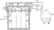
Please with reference to Fig. 1 and Fig. 3, Fig. 3 is the cutaway view of data machine room according to another embodiment of the present invention.Because the embodiment of present embodiment and Fig. 2 A is similar, therefore describe to different place.
Can be that one first chamber 110 and one second chamber, 120, the second chambers 120 are the tops that are positioned at first chamber 110 by district's lattice in the data machine room 100 of present embodiment.Wherein, first chamber 110 is a confined space, and meaning i.e. air in first chamber 110 does not circulate mutually with the air of external environment.Data rack 200 is positioned at first chamber 110.Heat pipe 130 has an evaporation ends 134 and a condenser 132, and the evaporation ends 134 of heat pipe 130 is positioned at first chamber 110, and the condenser 132 of heat pipe 130 is positioned at second chamber 120.In addition, data machine room 100 also can comprise a cooling line 152, and cooling line 152 combines with condenser 132, and cooling line 152 is in order to remove the heat energy of condenser 132.In addition, a cooling line 152 and an external cooling tower 150, cooling line 152 can circulate cooling fluid (for example cold water) through motor and pumping equipment in cooling line 152.In other words, the data machine room 100 of present embodiment can remove the heat energy of condenser 132 through the circulation of cooling fluid, makes first chamber 110 can have the good cooling effect.
Be noted that present embodiment is to be example with cooling line 152 collocation cooling towers 150, but non-in order to limit the present invention.For instance, can general rivers and creeks be replaced cooling tower 150, the kinetic energy that water flows is provided with the earth gravity that utilizes the Nature or pump is so that cooling fluid circulates in cooling line 152.
Please with reference to Fig. 1 and Fig. 4, Fig. 4 is the cutaway view of data machine room according to another embodiment of the present invention.Because the embodiment of present embodiment and Fig. 2 A is similar, therefore describe to different place.
Can be that one first chamber 110 and one second chamber, 120, the second chambers 120 are the top that is positioned at first chamber 110 by district's lattice in the data machine room 100 of present embodiment.Wherein, first chamber 110 is a confined space, and meaning i.e. air in first chamber 110 does not circulate mutually with the air of external environment.Data rack 200 is positioned at first chamber 110.Heat pipe 130 has an evaporation ends 134 and a condenser 132, and the evaporation ends 134 of heat pipe 130 is positioned at first chamber 110, and the condenser 132 of heat pipe 130 is positioned at second chamber 120.In addition, data machine room 100 also can comprise a cooling line 152, and cooling line 152 can an external cooling tower 150.One end of cooling line 152 also has a nozzle 154, and nozzle 154 is arranged at second chamber 120.Nozzle 154 can be with the cooling fluid in the cooling line 152, sprays condenser 132 or ventilating opening 122 places to heat pipe 130 with the appearance attitude of atomized drop.When evaporated by natural convection air, can absorb a large amount of heat owing to atomized drop.Therefore, the setting of such nozzle 154 can promote the efficient of the heat energy that removes condenser 132, and then promotes the system benefit of overall data machine room 100.
Please with reference to Fig. 1 and Fig. 5, Fig. 5 is the cutaway view of data machine room 100 according to another embodiment of the present invention.Because the embodiment of present embodiment and Fig. 3 A is similar, therefore describe to different place.
Can be the top that one first chamber 110 and one second chamber, 120, the second chambers 120 are positioned at first chamber 110 by district's lattice in the data machine room 100 of present embodiment.Wherein, first chamber 110 is a confined space, and meaning i.e. air in first chamber 110 does not circulate mutually with the air of external environment.Data rack 200 is positioned at first chamber 110.Heat pipe 130 has an evaporation ends 134 and a condenser 132, and the evaporation ends 134 of heat pipe 130 is positioned at first chamber 110, and the condenser 132 of heat pipe 130 is positioned at second chamber 120.Data machine room 100 also can comprise a cooling line 152, cooling line 152 external cooling towers 150.And cooling line 152 combines with condenser 132, and cooling line 152 is in order to remove the heat energy of condenser 132.In addition, data machine room 100 also comprises a heat exchanger 156, and heat exchanger 156 is arranged in first chamber 110.Can have runner in the heat exchanger 156, heat exchanger 156 combines with cooling line 152, and cooling fluid is flow in the heat exchanger 156.Through above-mentioned principle, can make the temperature decline of heat exchanger 156 and become a low-temperature receiver.Heat exchanger 156 can carry out heat exchange with the hot-air in first chamber 110, to reach the effect that reduces the temperature in first chamber 110.
In the present embodiment, be to set up heat exchanger 156 extra heat dissipation is provided.Thus, can also add the integral heat sink effect that promotes data machine room 10.
Please with reference to Fig. 1 and Fig. 6, Fig. 6 is the cutaway view of data machine room according to another embodiment of the present invention.Because present embodiment is the embodiment that the embodiment of Fig. 4 A is combined the relevant heat exchanger 156 of Fig. 5, therefore describe to different place.
Can be the top that one first chamber 110 and one second chamber, 120, the second chambers 120 are positioned at first chamber 110 by district's lattice in the data machine room 100 of present embodiment.Wherein, first chamber 110 is a confined space, and meaning i.e. air in first chamber 110 does not circulate mutually with the air of external environment.Data rack 200 is positioned at first chamber 110.Heat pipe 130 has an evaporation ends 134 and a condenser 132, and the evaporation ends 134 of heat pipe 130 is positioned at first chamber 110, and the condenser 132 of heat pipe 130 is positioned at second chamber 120.In addition, data machine room 100 also can comprise a cooling line 152, and cooling line 152 can an external cooling tower 150.One end of cooling line 152 also has a nozzle 154, and nozzle 154 is arranged at second chamber 120.Nozzle 154 can be with the cooling fluid in the cooling line 152, sprays condenser 132 or ventilating opening 122 places to heat pipe 130 with the appearance attitude of atomized drop.Atomized drop receives natural convection air and when evaporating, can absorb a large amount of heat to remove the heat energy of condenser 132.In addition, data machine room 100 also comprises a heat exchanger 156, and heat exchanger 156 is arranged in first chamber 110.Can have runner in the heat exchanger 156, heat exchanger 156 combines with cooling line 152, and cooling fluid is flow in the heat exchanger 156.Through above-mentioned principle, can make the temperature decline of heat exchanger 156 and become a low-temperature receiver.Heat exchanger 156 can carry out heat exchange with the hot-air in first chamber 110, to reach the effect that reduces the temperature in first chamber 110.Therefore, be with the setting of such nozzle 154 with heat exchanger 156, can promote the system benefit of overall data machine room 100.
Please with reference to Fig. 1 and Fig. 7, Fig. 7 is the cutaway view of data machine room according to another embodiment of the present invention.Because the embodiment of present embodiment and Fig. 5 is similar, therefore describe to different place.
Can be the top that one first chamber 110 and one second chamber, 120, the second chambers 120 are positioned at first chamber 110 by district's lattice in the data machine room 100 of present embodiment.Wherein, first chamber 110 is a confined space, and meaning i.e. air in first chamber 110 does not circulate mutually with the air of external environment.Data rack 200 is positioned at first chamber 110.Heat pipe 130 has an evaporation ends 134 and a condenser 132, and the evaporation ends 134 of heat pipe 130 is positioned at first chamber 110, and the condenser 132 of heat pipe 130 is positioned at second chamber 120.Data machine room 100 also can comprise a cooling line 152, cooling line 152 external cooling towers 150.And cooling line 152 combines with condenser 132, and cooling line 152 is in order to remove the heat energy of condenser 132.In addition, data machine room 100 also comprises a heat exchanger 156, and heat exchanger 156 is arranged in first chamber 110.Can have runner in the heat exchanger 156, heat exchanger 156 combines with cooling line 152, and cooling fluid is flow in the heat exchanger 156.Through above-mentioned principle, can make the temperature decline of heat exchanger 156 and become a low-temperature receiver.And the data machine room 100 of present embodiment also can comprise a freezing equipment 160, and freezing equipment 160 connects heat exchanger 156 and cooling tower 150 respectively through cooling line 152.Freezing equipment 160 can comprise a compressor, a condenser, an expansion valve and an evaporator.Liquid vapour two phase change of freezing equipment 160 refrigerants capable of using and reduce the cooling fluid temperature in the cooling line 152 make the cooling fluid cooling in the frozen water inflow heat exchanger 156.Thus, the thermal source more than heat exchanger 156 can absorb in first chamber 110.
Please with reference to Fig. 1 and Fig. 8, Fig. 8 is the cutaway view of data machine room according to another embodiment of the present invention.Because the embodiment of present embodiment and Fig. 6 is similar, therefore describe to different place.
Can be the top that one first chamber 110 and one second chamber, 120, the second chambers 120 are positioned at first chamber 110 by district's lattice in the data machine room 100 of present embodiment.Wherein, first chamber 110 is a confined space, and meaning i.e. air in first chamber 110 does not circulate mutually with the air of external environment.Data rack 200 is positioned at first chamber 110.Heat pipe 130 has an evaporation ends 134 and a condenser 132, and the evaporation ends 134 of heat pipe 130 is positioned at first chamber 110, and the condenser 132 of heat pipe 130 is positioned at second chamber 120.In addition, data machine room 100 also can comprise a cooling line 152, and cooling line 152 can an external cooling tower 150.One end of cooling line 152 also has a nozzle 154, and nozzle 154 is arranged at second chamber 120.Nozzle 154 can be with the cooling fluid in the cooling line 152, sprays condenser 132 or ventilating opening 122 places to heat pipe 130 with the appearance attitude of atomized drop.Atomized drop receives natural convection air and when evaporating, can absorb a large amount of heat to remove the heat energy of condenser 132.
In addition, data machine room 100 also comprises a heat exchanger 156, and heat exchanger 156 is arranged in first chamber 110.Can have runner in the heat exchanger 156, heat exchanger 156 combines with cooling line 152, and cooling fluid is flow in the heat exchanger 156.Through above-mentioned principle, can make the temperature decline of heat exchanger 156 and become a low-temperature receiver.And the data machine room 100 of present embodiment also can comprise a freezing equipment 160, and freezing equipment 160 connects heat exchanger 156 and cooling tower 150 respectively through cooling line 152.Freezing equipment 160 can comprise a compressor, a condenser, an expansion valve and an evaporator.Two phase change of freezing equipment 160 refrigerants capable of using and reduce the cooling fluid temperature in the cooling line 152 make the cooling fluid cooling in the frozen water inflow heat exchanger 156.Thus, the thermal source more than heat exchanger 156 can absorb in first chamber 110.
Please with reference to Fig. 9 A to Fig. 9 D, Fig. 9 A is the structural perspective of data machine room according to another embodiment of the present invention.Fig. 9 B is the cutaway view according to the data machine room of the 9B-9B hatching of Fig. 9 A, and Fig. 9 C is the cutaway view according to the data machine room of the 9C-9C hatching of Fig. 9 A, and Fig. 9 D is according to the cutaway view of another embodiment of the present invention along the data machine room of the 9D-9D hatching of Fig. 9 A.Because the embodiment of present embodiment and Fig. 2 A is similar, therefore describe to different place.
The evaporation ends 134 of the data machine room 100 of present embodiment can be extended to the below in first chamber 110 by the top in first chamber 110, and evaporation ends 134 can be between two data racks 200, shown in Fig. 9 A and Fig. 9 B.
Also can set up one first fan 180 and one second fan 190 in the data machine room 10.First fan 180 is arranged in first chamber 110, and the air outlet of first fan 180 is towards evaporation ends 134.First fan 180 turns round and produces the distinguished and admirable evaporation ends 134 that blows, and uses and in first chamber 110, produces forced convertion, shown in Fig. 9 C, to promote the heat exchanger effectiveness in first chamber 110.In addition, second fan 190 is arranged in second chamber 120, and contiguous condenser 132.Second fan 190 turns round and produces forced convertion, the heat energy on the condenser 132 can be removed faster, shown in Fig. 9 D by cool ambient air.
Be noted that the data machine room 100 of present embodiment is to set up first fan 180 and second fan 190, to reach the effect of forced convertion.Yet when utilizing fan to carry out forced convertion, the position that fan is put, ventilating opening 122 are offered the example that the appearance attitude institute matched combined of position and the circulation of air flow of position, heat pipe 130 comes out can be very multiple.The accompanying drawing of present embodiment is to take wherein an example to explain, but non-in order to limitation the present invention, can reach the effect of forced draft circulation as long as set up fan, all within the scope of the invention.
According to the data machine room that the invention described above one embodiment is disclosed, be the heat energy in first chamber to be expelled to second chamber through heat pipe.And first chamber that thermal source was positioned at is a confined space.Therefore, under the situation that outside air does not need directly with thermal source contacts, can reach radiating effect.So such data machine room can avoid thermal source to receive the pollution of outside air.And the data machine room of present embodiment can also be aided with the setting that nozzle sprays atomized drop and cooling water pipe, heat exchanger, freezing equipment and fan, promotes the cooling effectiveness of data machine room.
Certainly; The present invention also can have other various embodiments; Under the situation that does not deviate from spirit of the present invention and essence thereof; Those of ordinary skill in the art work as can make various corresponding changes and distortion according to the present invention, but these corresponding changes and distortion all should belong to the protection range of the appended claim of the present invention.
Claims (12)
1. a data machine room in order to many modems at least one data rack are dispelled the heat, is characterized in that, this data machine room comprises:
One first chamber, this data rack is positioned at this first chamber;
One second chamber, contiguous this first chamber; And
One heat pipe has an evaporation ends and a condenser, and this evaporation ends is positioned at this first chamber, and this condenser is positioned at this second chamber;
Wherein, this heat pipe absorbs the heat energy of being discharged by this data rack in this first chamber through this evaporation ends, and with thermal energy transfer to this condenser, and heat energy is got rid of through this condenser.
2. data machine room according to claim 1 is characterized in that, this second chamber also has at least one ventilating opening, and this ventilating opening is communicated with external environment, and the gas of this second chamber and the gas of external environment produce free convection and the heat energy of this condenser is got rid of.
3. data machine room according to claim 1 is characterized in that, also comprises a cooling line, and an end of this cooling line has a nozzle, and this nozzle is arranged at this second chamber, this nozzles spray atomized liquid to this condenser or a ventilating opening place.
4. data machine room according to claim 3 is characterized in that, also comprises a heat exchanger, and this heat exchanger is arranged in this first chamber, and this heat exchanger connects this cooling line.
5. data machine room according to claim 4 is characterized in that, also comprises a freezing equipment, and this freezing equipment connects this heat exchanger through this cooling line.
6. data machine room according to claim 1 is characterized in that, also comprises a cooling line, and this cooling line combines with this condenser of this heat pipe, and this cooling line is got rid of the heat energy of this condenser.
7. data machine room according to claim 6 is characterized in that, also comprises a heat exchanger, and this heat exchanger is arranged in this first chamber, and this heat exchanger connects this cooling line.
8. data machine room according to claim 7 is characterized in that, also comprises a freezing equipment, and this freezing equipment connects this heat exchanger through this cooling line.
9. data machine room according to claim 1 is characterized in that, also comprises one first fan, is arranged in this first chamber, and in this first chamber, produces forced convertion.
10. data machine room according to claim 1 is characterized in that, also comprises one second fan, is arranged in this second chamber, and in this second chamber, produces forced convertion.
11., it is characterized in that this cooling line is connected with a cooling tower according to claim 3,4,5,6,7 or 8 described data machine rooms.
12. according to claim 3,4,5,6,7 or 8 described data machine rooms, it is characterized in that this cooling line is connected with a pump, a cooling fluid circulated in this cooling line.
Applications Claiming Priority (2)
| Application Number | Priority Date | Filing Date | Title |
|---|---|---|---|
| TW099137335 | 2010-10-29 | ||
| TW099137335A TWI422318B (en) | 2010-10-29 | 2010-10-29 | Data center module |
Publications (2)
| Publication Number | Publication Date |
|---|---|
| CN102548357A true CN102548357A (en) | 2012-07-04 |
| CN102548357B CN102548357B (en) | 2015-01-21 |
Family
ID=45996527
Family Applications (1)
| Application Number | Title | Priority Date | Filing Date |
|---|---|---|---|
| CN201110334726.5A Active CN102548357B (en) | 2010-10-29 | 2011-10-26 | Data machine room |
Country Status (3)
| Country | Link |
|---|---|
| US (2) | US8441789B2 (en) |
| CN (1) | CN102548357B (en) |
| TW (1) | TWI422318B (en) |
Cited By (4)
| Publication number | Priority date | Publication date | Assignee | Title |
|---|---|---|---|---|
| CN102905507A (en) * | 2012-10-17 | 2013-01-30 | 深圳市英维克科技有限公司 | Hot environment controlling system |
| CN104501326A (en) * | 2014-11-12 | 2015-04-08 | 北京百度网讯科技有限公司 | Heat-dissipating system and method |
| CN105805866A (en) * | 2014-12-31 | 2016-07-27 | 中国移动通信集团公司 | Air cooling system for machine room |
| CN109163398A (en) * | 2018-10-09 | 2019-01-08 | 郑州云海信息技术有限公司 | A kind of high density single cabinet formula data center |
Families Citing this family (54)
| Publication number | Priority date | Publication date | Assignee | Title |
|---|---|---|---|---|
| US9496200B2 (en) | 2011-07-27 | 2016-11-15 | Coolit Systems, Inc. | Modular heat-transfer systems |
| US9943014B2 (en) | 2013-03-15 | 2018-04-10 | Coolit Systems, Inc. | Manifolded heat exchangers and related systems |
| DE102008030308A1 (en) | 2008-06-30 | 2009-12-31 | Lindenstruth, Volker, Prof. | Building for a data center with facilities for efficient cooling |
| JP2013509709A (en) * | 2009-11-02 | 2013-03-14 | テレフオンアクチーボラゲット エル エム エリクソン(パブル) | Passive cabinet cooling |
| FR2954670B1 (en) * | 2009-12-22 | 2017-06-09 | Atrium Data | METHOD AND DEVICE FOR REDUCING THE ENERGY CONSUMPTION OF A CENTER COMPRISING ENERGY EQUIPMENT. |
| US8472181B2 (en) | 2010-04-20 | 2013-06-25 | Cray Inc. | Computer cabinets having progressive air velocity cooling systems and associated methods of manufacture and use |
| CN103069246B (en) | 2010-06-24 | 2016-02-03 | 北狄空气应对加拿大公司 | Liquid-to-air membrane energy exchanger |
| TW201210454A (en) * | 2010-08-24 | 2012-03-01 | Hon Hai Prec Ind Co Ltd | Server cabinet and liquid cooling system thereof |
| WO2012027319A1 (en) | 2010-08-26 | 2012-03-01 | Asetek A/S | Liquid cooling system for a server |
| TW201221034A (en) * | 2010-11-05 | 2012-05-16 | Inventec Corp | Cooling system of server and cooling method thereof |
| US8915092B2 (en) | 2011-01-19 | 2014-12-23 | Venmar Ces, Inc. | Heat pump system having a pre-processing module |
| WO2014141162A1 (en) | 2013-03-15 | 2014-09-18 | Coolit Systems, Inc. | Sensors, multiplexed communication techniques, and related systems |
| US10365667B2 (en) | 2011-08-11 | 2019-07-30 | Coolit Systems, Inc. | Flow-path controllers and related systems |
| US9810439B2 (en) | 2011-09-02 | 2017-11-07 | Nortek Air Solutions Canada, Inc. | Energy exchange system for conditioning air in an enclosed structure |
| CN103931279B (en) * | 2011-11-08 | 2016-08-17 | 松下知识产权经营株式会社 | The chiller of cooler rack server and the data center possessing this chiller |
| TWI445493B (en) * | 2011-11-11 | 2014-07-11 | Inventec Corp | Heat dissipation system |
| US9155230B2 (en) | 2011-11-28 | 2015-10-06 | Asetek Danmark A/S | Cooling system for a server |
| TWI459893B (en) * | 2012-01-20 | 2014-11-01 | Delta Electronics Inc | Cabinet system and air-exhausting equipment thereof |
| EP2663172A1 (en) * | 2012-05-11 | 2013-11-13 | eCube Computing GmbH | Method for operating a data centre with efficient cooling means |
| CN103596297B (en) * | 2012-08-13 | 2017-04-12 | 华为技术有限公司 | Radio remote unit devices and assemblies thereof |
| US9816760B2 (en) | 2012-08-24 | 2017-11-14 | Nortek Air Solutions Canada, Inc. | Liquid panel assembly |
| US9772124B2 (en) | 2013-03-13 | 2017-09-26 | Nortek Air Solutions Canada, Inc. | Heat pump defrosting system and method |
| US9109808B2 (en) | 2013-03-13 | 2015-08-18 | Venmar Ces, Inc. | Variable desiccant control energy exchange system and method |
| US10352628B2 (en) | 2013-03-14 | 2019-07-16 | Nortek Air Solutions Canada, Inc. | Membrane-integrated energy exchange assembly |
| US10584884B2 (en) | 2013-03-15 | 2020-03-10 | Nortek Air Solutions Canada, Inc. | Control system and method for a liquid desiccant air delivery system |
| US11408681B2 (en) * | 2013-03-15 | 2022-08-09 | Nortek Air Solations Canada, Iac. | Evaporative cooling system with liquid-to-air membrane energy exchanger |
| US9351430B2 (en) * | 2013-06-13 | 2016-05-24 | Microsoft Technology Licensing, Llc | Renewable energy based datacenter cooling |
| KR101511053B1 (en) * | 2014-01-23 | 2015-04-10 | 김광수 | Ventilation of hygienic carriage container for livestock |
| AU2015306040A1 (en) | 2014-08-19 | 2017-04-06 | Nortek Air Solutions Canada, Inc. | Liquid to air membrane energy exchangers |
| CN104244681B (en) * | 2014-09-29 | 2017-02-15 | 中国移动通信集团广东有限公司 | Cooling system of heat-pipe external-circulation type secondary coolant loop server cabinet |
| CN104780746A (en) * | 2015-04-30 | 2015-07-15 | 唐佳 | Water-cooled cabinets and underwater water-cooled system with same |
| US9445531B1 (en) * | 2015-05-01 | 2016-09-13 | Baidu Usa Llc | Air washing for open air cooling of data centers |
| EP3985322A3 (en) | 2015-05-15 | 2022-08-31 | Nortek Air Solutions Canada, Inc. | Air conditioning system with a liquid to air membrane energy exchanger |
| US11092349B2 (en) | 2015-05-15 | 2021-08-17 | Nortek Air Solutions Canada, Inc. | Systems and methods for providing cooling to a heat load |
| US10808951B2 (en) | 2015-05-15 | 2020-10-20 | Nortek Air Solutions Canada, Inc. | Systems and methods for providing cooling to a heat load |
| AU2016281963A1 (en) | 2015-06-26 | 2018-02-15 | Nortek Air Solutions Canada, Inc. | Three-fluid liquid to air membrane energy exchanger |
| TWI620899B (en) * | 2016-12-05 | 2018-04-11 | 誼昌空調工程有限公司 | Ventilation system for data room |
| CN107257608A (en) * | 2017-01-18 | 2017-10-17 | 惠科股份有限公司 | The waterproof construction of cold passage rack |
| EP3612771B1 (en) | 2017-04-18 | 2023-03-22 | Nortek Air Solutions Canada, Inc. | Desiccant enhanced evaporative cooling systems and methods |
| CN107333458A (en) * | 2017-09-06 | 2017-11-07 | 合肥同诺文化科技有限公司 | Communication apparatus heat exchanger |
| CN107801362B (en) * | 2017-11-29 | 2019-11-22 | 北京百度网讯科技有限公司 | Cooling system for data center |
| CN108990396A (en) * | 2018-09-21 | 2018-12-11 | 深圳绿色云图科技有限公司 | Liquid cooling cabinet and liquid cooling base station |
| CN109661150B (en) * | 2018-12-28 | 2020-09-11 | 杭州龙云水利机械制造有限公司 | Control cabinet |
| US11662037B2 (en) | 2019-01-18 | 2023-05-30 | Coolit Systems, Inc. | Fluid flow control valve for fluid flow systems, and methods |
| US11473860B2 (en) | 2019-04-25 | 2022-10-18 | Coolit Systems, Inc. | Cooling module with leak detector and related systems |
| EP4003620A4 (en) * | 2019-08-19 | 2023-08-16 | Roth, Jason Todd | Data center cooling system and related methods |
| CN110602930A (en) * | 2019-10-08 | 2019-12-20 | 广州同方瑞风节能科技股份有限公司 | Data center machine room system |
| US11076508B2 (en) * | 2019-11-14 | 2021-07-27 | Baidu Usa Llc | Cooling systems for immersion cooled IT equipment |
| US10980154B1 (en) * | 2019-12-23 | 2021-04-13 | Baidu Usa Llc | Cooling design for PCIE mounted server peripheral electronics |
| US11672105B2 (en) * | 2020-01-16 | 2023-06-06 | Meta Platforms, Inc. | Data center cooling using a heat pipe |
| EP4150216A4 (en) | 2020-05-11 | 2023-11-01 | Coolit Systems, Inc. | Liquid pumping units, and related systems and methods |
| CN112399758B (en) * | 2020-11-25 | 2021-12-10 | 内蒙古大唐国际托克托发电有限责任公司 | Electric power detection device with good heat dissipation effect |
| CN112954974B (en) * | 2021-02-08 | 2022-05-10 | 浙江佳环工程技术有限公司 | Working method of high-voltage frequency converter spray cooling system |
| CN113163689B (en) * | 2021-04-21 | 2022-07-12 | 西安交通大学 | Low-power consumption natural evaporation cooling server rack |
Citations (4)
| Publication number | Priority date | Publication date | Assignee | Title |
|---|---|---|---|---|
| CN201039641Y (en) * | 2007-04-13 | 2008-03-19 | 南京师范大学 | Air conditioner for machine room |
| US20090161312A1 (en) * | 2006-02-16 | 2009-06-25 | Liebert Corporation | Liquid cooling systems for server applications |
| CN101509684A (en) * | 2009-03-10 | 2009-08-19 | 尹宏文 | Communication equipment room energy-conserving system |
| CN101713578A (en) * | 2009-11-04 | 2010-05-26 | 中节能(北京)空调节能科技有限公司 | Uncompressed integrated air conditioning equipment |
Family Cites Families (28)
| Publication number | Priority date | Publication date | Assignee | Title |
|---|---|---|---|---|
| AU674057B2 (en) | 1993-04-23 | 1996-12-05 | Liebert Corporation | Modular floor sub-structure for the operational support of computer systems |
| US5718117A (en) | 1996-04-10 | 1998-02-17 | Motorola, Inc. | Apparatus and method for spray-cooling an electronic module |
| US6557624B1 (en) | 2000-08-09 | 2003-05-06 | Liebert Corporation | Configurable system and method for cooling a room |
| US6574104B2 (en) | 2001-10-05 | 2003-06-03 | Hewlett-Packard Development Company L.P. | Smart cooling of data centers |
| US6700785B2 (en) * | 2002-01-04 | 2004-03-02 | Intel Corporation | Computer system which locks a server unit subassembly in a selected position in a support frame |
| US7500911B2 (en) | 2002-11-25 | 2009-03-10 | American Power Conversion Corporation | Exhaust air removal system |
| US6775137B2 (en) | 2002-11-25 | 2004-08-10 | International Business Machines Corporation | Method and apparatus for combined air and liquid cooling of stacked electronics components |
| JP4199018B2 (en) * | 2003-02-14 | 2008-12-17 | 株式会社日立製作所 | Rack mount server system |
| US6859366B2 (en) | 2003-03-19 | 2005-02-22 | American Power Conversion | Data center cooling system |
| US6819563B1 (en) * | 2003-07-02 | 2004-11-16 | International Business Machines Corporation | Method and system for cooling electronics racks using pre-cooled air |
| TWM251439U (en) * | 2003-08-07 | 2004-11-21 | Cq Inc | Electronic equipment cabinet |
| US7345877B2 (en) * | 2005-01-06 | 2008-03-18 | The Boeing Company | Cooling apparatus, system, and associated method |
| US7315448B1 (en) * | 2005-06-01 | 2008-01-01 | Hewlett-Packard Development Company, L.P. | Air-cooled heat generating device airflow control system |
| US7403393B2 (en) * | 2005-12-28 | 2008-07-22 | International Business Machines Corporation | Apparatus and system for cooling heat producing components |
| TWM295763U (en) * | 2006-03-07 | 2006-08-11 | Giga Byte Tech Co Ltd | Water-cooling heat dissipation module device |
| US7511960B2 (en) | 2006-09-13 | 2009-03-31 | Sun Microsystems, Inc. | Balanced chilled fluid cooling system for a data center in a shipping container |
| TWM311709U (en) | 2006-09-29 | 2007-05-11 | Chang-Ren Chen | Ceiling structure capable of heat-absorbing |
| US8395896B2 (en) * | 2007-02-24 | 2013-03-12 | Hewlett-Packard Development Company, L.P. | Redundant cooling systems and methods |
| US7430118B1 (en) * | 2007-06-04 | 2008-09-30 | Yahoo! Inc. | Cold row encapsulation for server farm cooling system |
| TWM326135U (en) | 2007-06-08 | 2008-01-21 | Nat Chin Yi University Of Tech | Air conditioning structure capable of promoting cold air efficiency with nebulized water |
| DE102007045733B3 (en) * | 2007-09-25 | 2009-02-05 | Qimonda Ag | Memory module comprises board with two sides, where memory chips are arranged on former and latter side, where longitudinally proceeding heat pipe module is arranged on former side |
| US7626820B1 (en) * | 2008-05-15 | 2009-12-01 | Sun Microsystems, Inc. | Thermal transfer technique using heat pipes with integral rack rails |
| TWM346849U (en) * | 2008-07-10 | 2008-12-11 | de-yin Xie | Iced water circulation type cooling device for server |
| CN101902895A (en) * | 2009-05-27 | 2010-12-01 | 鸿富锦精密工业(深圳)有限公司 | Cooling system |
| US8582298B2 (en) * | 2009-06-22 | 2013-11-12 | Xyber Technologies | Passive cooling enclosure system and method for electronics devices |
| CN102577654B (en) * | 2009-09-29 | 2015-02-11 | 日本电气株式会社 | Heat conveying structure for electronic device |
| TWM383280U (en) * | 2009-12-28 | 2010-06-21 | Chunghwa Telecom Co Ltd | Mechanic cabinet |
| US8385069B2 (en) * | 2010-05-24 | 2013-02-26 | International Business Machines Corporation | Liquid coolant conduit secured in an unused socket for memory module cooling |
-
2010
- 2010-10-29 TW TW099137335A patent/TWI422318B/en active
- 2010-12-29 US US12/981,124 patent/US8441789B2/en active Active
-
2011
- 2011-10-26 CN CN201110334726.5A patent/CN102548357B/en active Active
-
2013
- 2013-03-07 US US13/789,285 patent/US9137931B2/en active Active
Patent Citations (4)
| Publication number | Priority date | Publication date | Assignee | Title |
|---|---|---|---|---|
| US20090161312A1 (en) * | 2006-02-16 | 2009-06-25 | Liebert Corporation | Liquid cooling systems for server applications |
| CN201039641Y (en) * | 2007-04-13 | 2008-03-19 | 南京师范大学 | Air conditioner for machine room |
| CN101509684A (en) * | 2009-03-10 | 2009-08-19 | 尹宏文 | Communication equipment room energy-conserving system |
| CN101713578A (en) * | 2009-11-04 | 2010-05-26 | 中节能(北京)空调节能科技有限公司 | Uncompressed integrated air conditioning equipment |
Cited By (6)
| Publication number | Priority date | Publication date | Assignee | Title |
|---|---|---|---|---|
| CN102905507A (en) * | 2012-10-17 | 2013-01-30 | 深圳市英维克科技有限公司 | Hot environment controlling system |
| CN102905507B (en) * | 2012-10-17 | 2013-08-28 | 深圳市英维克科技有限公司 | Hot environment controlling system |
| CN104501326A (en) * | 2014-11-12 | 2015-04-08 | 北京百度网讯科技有限公司 | Heat-dissipating system and method |
| CN104501326B (en) * | 2014-11-12 | 2017-08-11 | 北京百度网讯科技有限公司 | A kind of cooling system and method |
| CN105805866A (en) * | 2014-12-31 | 2016-07-27 | 中国移动通信集团公司 | Air cooling system for machine room |
| CN109163398A (en) * | 2018-10-09 | 2019-01-08 | 郑州云海信息技术有限公司 | A kind of high density single cabinet formula data center |
Also Published As
| Publication number | Publication date |
|---|---|
| CN102548357B (en) | 2015-01-21 |
| TW201218935A (en) | 2012-05-01 |
| US9137931B2 (en) | 2015-09-15 |
| US8441789B2 (en) | 2013-05-14 |
| US20130182388A1 (en) | 2013-07-18 |
| TWI422318B (en) | 2014-01-01 |
| US20120106073A1 (en) | 2012-05-03 |
Similar Documents
| Publication | Publication Date | Title |
|---|---|---|
| CN102548357B (en) | Data machine room | |
| Yuan et al. | Phase change cooling in data centers: A review | |
| FI119705B (en) | Phase change heat exchanger | |
| KR102502979B1 (en) | air conditioning system | |
| CN103175324A (en) | Concurrent flow evaporative type condensation refrigerating unit with heat recovery | |
| CN204285886U (en) | Semiconductor refrigerating heating cycle system | |
| CN101266104A (en) | Low energy consumption or entirely passive type heat quantity transfer device | |
| CN105135739A (en) | Multifunctional heat pump type evaporative condensing air-conditioning unit | |
| CN102705927B (en) | A kind of ice conserve cold accumulation of heat super low temperature heat pump air-conditioning | |
| CN201497089U (en) | Evaporative condensing computer room air conditioner | |
| US11297742B2 (en) | Thermal containment system with integrated cooling unit for waterborne or land-based data centers | |
| US9448001B2 (en) | Indirect cooling unit | |
| CN203824158U (en) | Multifunctional ground source heat pump unit | |
| CN102467202A (en) | Cooling system of server and method for cooling electronic device | |
| CN201909410U (en) | Semiconductor air conditioner | |
| KR102174983B1 (en) | Artificial intelligence in the outdoor resetis remarkebly low cooling systems | |
| CN103105019A (en) | Vermicelli drying process heat recovery heat pump air-conditioning system | |
| CN213514496U (en) | Self-descaling double-cooling heat pump unit | |
| CN205481611U (en) | Cooling device and possess this cooling device's air conditioner | |
| CN107182188B (en) | Outdoor airtight cabinet and heat abstractor thereof | |
| CN106931565A (en) | Cooling device and has the air-conditioning of the cooling device | |
| CN103697623A (en) | Heat-accumulating-type refrigerator | |
| CN205227634U (en) | Ice source how online group of heat pump | |
| CN104582419A (en) | Heat exchanger for communication cabinet | |
| CN205138006U (en) | Sleeve pipe evaporative condenser |
Legal Events
| Date | Code | Title | Description |
|---|---|---|---|
| C06 | Publication | ||
| PB01 | Publication | ||
| C10 | Entry into substantive examination | ||
| SE01 | Entry into force of request for substantive examination | ||
| C14 | Grant of patent or utility model | ||
| GR01 | Patent grant |