WO2025142410A1 - 構造部材の製造方法、構造部材、及び金型セット - Google Patents
構造部材の製造方法、構造部材、及び金型セット Download PDFInfo
- Publication number
- WO2025142410A1 WO2025142410A1 PCT/JP2024/043312 JP2024043312W WO2025142410A1 WO 2025142410 A1 WO2025142410 A1 WO 2025142410A1 JP 2024043312 W JP2024043312 W JP 2024043312W WO 2025142410 A1 WO2025142410 A1 WO 2025142410A1
- Authority
- WO
- WIPO (PCT)
- Prior art keywords
- top plate
- continuous flange
- vertical wall
- molding
- mold
- Prior art date
- Legal status (The legal status is an assumption and is not a legal conclusion. Google has not performed a legal analysis and makes no representation as to the accuracy of the status listed.)
- Pending
Links
Images








Classifications
-
- B—PERFORMING OPERATIONS; TRANSPORTING
- B21—MECHANICAL METAL-WORKING WITHOUT ESSENTIALLY REMOVING MATERIAL; PUNCHING METAL
- B21D—WORKING OR PROCESSING OF SHEET METAL OR METAL TUBES, RODS OR PROFILES WITHOUT ESSENTIALLY REMOVING MATERIAL; PUNCHING METAL
- B21D22/00—Shaping without cutting, by stamping, spinning, or deep-drawing
- B21D22/20—Deep-drawing
- B21D22/26—Deep-drawing for making peculiarly, e.g. irregularly, shaped articles
Definitions
- Patent Document 3 discloses a method for manufacturing a structural member having a T-shape in plan view.
- the manufacturing method of Patent Document 3 includes a first forming step in which a metal plate is formed into an intermediate shaped member by drawing, a trimming step in which the intermediate shaped member is trimmed, and a second forming step in which the trimmed intermediate shaped member is formed into a structural member by foam molding.
- a structural member of the target shape is press-formed using a mold including an upper mold and a lower mold.
- the objective of this disclosure is to provide a manufacturing method for structural components that can suppress the occurrence of cracks in continuous flanges.
- the manufacturing method disclosed herein is a method for manufacturing a structural member including a member body and a continuous flange.
- the member body includes a first top plate and a first vertical wall.
- the first vertical wall is connected to the first top plate via a first ridge portion.
- the continuous flange includes a second top plate and a second vertical wall.
- the second top plate is provided continuous with the first top plate.
- the second vertical wall is connected to the second top plate via a second ridge portion and is provided continuous with the first vertical wall.
- the structural member has a corner portion between the first ridge portion and the second ridge portion.
- the manufacturing method includes a first step of bending a material using a first mold to form a continuous flange, and a second step of further bending the continuous flange using a second mold so that the angle between the second top plate and the second vertical wall when viewed from the edge of the continuous flange is smaller than that in the first step.
- a plane that passes through the intersection of the second top plate and the second vertical wall and is perpendicular to the opening and closing direction of the first mold is taken as the reference horizontal plane
- the second top plate is inclined so as to open to the opposite side of the second vertical wall relative to the reference horizontal plane.
- the manufacturing method for structural components disclosed herein can prevent cracks from occurring in continuous flanges.
- FIG. 1 is a perspective view of a structural member according to a first embodiment.
- FIG. 2A is a diagram showing a mold set according to the first embodiment.
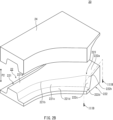
- FIG. 2B is a diagram showing a mold set according to the first embodiment.
- FIG. 3A is a cross-sectional view taken along line IIIA-IIIA of FIG. 2A.
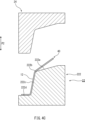
- FIG. 3B is a cross-sectional view taken along line IIIB-IIIB of FIG. 2B.
- FIG. 4A is a schematic diagram for explaining the manufacturing method of the structural member according to the first embodiment.
- FIG. 4B is a schematic diagram for explaining the manufacturing method of the structural member according to the first embodiment.
- FIG. 4C is a schematic view for explaining the manufacturing method of the structural member according to the first embodiment.
- FIG. 4D is a schematic diagram for explaining the manufacturing method of the structural member according to the first embodiment.
- FIG. 4E is a schematic diagram for explaining the manufacturing method of a structural member according to the first embodiment.
- FIG. 4F is a schematic diagram for explaining the manufacturing method of the structural member according to the first embodiment.
- FIG. 4G is a schematic view for explaining the manufacturing method of a structural member according to the first embodiment.
- FIG. 4H is a schematic diagram for explaining the manufacturing method of the structural member according to the first embodiment.
- FIG. 5 is a partial enlarged view of the structural member shown in FIG.
- FIG. 6 is a diagram for explaining a mold set according to the second embodiment.
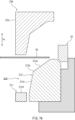
- FIG. 7A is a schematic diagram for explaining a manufacturing method of a structural member according to the second embodiment.
- the manufacturing method according to the embodiment is a method for manufacturing a structural member including a member body and a continuous flange.
- the member body includes a first top plate and a first vertical wall.
- the first vertical wall is connected to the first top plate via a first ridge portion.
- the continuous flange includes a second top plate and a second vertical wall.
- the second top plate is provided continuous with the first top plate.
- the second vertical wall is connected to the second top plate via the second ridge portion and is provided continuous with the first vertical wall.
- the structural member has a corner portion between the first ridge portion and the second ridge portion.
- the material is bent to form a continuous flange
- the continuous flange after the first step is further bent.
- the continuous flange is formed so that the angle between the top plate (second top plate) and the vertical wall (second vertical wall) of the continuous flange is larger than in the second step, and in the second step, the continuous flange is bent so that the angle is smaller.
- the second top plate is inclined so as to open to the opposite side of the second vertical wall with respect to the reference horizontal plane.
- the flow of material from the second top plate to the second vertical wall side can be promoted, and the degree of thickness reduction in the continuous flange can be mitigated.
- the strain generated in the continuous flange can be dispersed.
- the occurrence of cracks in the continuous flange can be suppressed. For example, even if the radius of curvature of the corner between the component body and the continuous flange is small, cracks are less likely to occur in the continuous flange.
- the forming process may be performed with excess material provided in advance on the metal plate (blank) to prevent cracks, and the unnecessary excess material may be removed by performing a trimming process after the forming process.
- the continuous flange is formed by a two-stage bending process so that the bending angle in the second process is smaller than that in the first process, thereby suppressing cracks in the continuous flange. Therefore, it is not necessary to provide excess material to the material to prevent cracks in the continuous flange, and the trimming process of the excess material after the forming process can be omitted.
- the amount of material input to the forming process can be reduced compared to when the trimming process is performed. Therefore, the yield rate in the manufacturing of structural members can be improved. In addition, the amount of material input is reduced and the trimming process is not performed, which reduces the amount of transportation and electricity required in the manufacturing of structural members, and therefore reduces greenhouse gas emissions.
- ⁇ 1- ⁇ 2 may be 10° or more (second configuration).
- the angle (bending angle) ⁇ 1 between the second top plate and the second vertical wall of the continuous flange in the first step is 10° or more larger than the bending angle ⁇ 2 in the second step.
- the flow of material from the second top plate to the second vertical wall side is more likely to be promoted in the first step. This makes it possible to further reduce the degree of thickness reduction in the continuous flange, making it even less likely for cracks to occur in the continuous flange.
- ⁇ 1- ⁇ 2 may be 70° or less (third configuration).
- the first mold can include a member body molding section for molding the member body, and a continuous flange molding section for molding the continuous flange.
- the continuous flange molding section may be separate from the member body molding section.
- the continuous flange molding section can start molding the continuous flange after the member body molding section starts molding the member body (fourth configuration).
- the forming of the main body of the component begins prior to the forming of the continuous flange.
- the continuous flange is not constrained by the first mold. This makes it easier for material to flow from the second top plate to the second vertical wall in the continuous flange, and makes it possible to further suppress reduction in plate thickness. This makes it less likely for cracks to occur in the continuous flange.
- A1 When the maximum thickness reduction rate based on the thickness of the first top plate measured along the edge of the continuous flange in an area 10.0 mm toward the second top plate from the boundary between the second ridge line portion and the second top plate is A1, and the maximum thickness reduction rate based on the thickness of the first top plate measured along the edge of the continuous flange in an area 50.0 mm toward the second vertical wall from the boundary between the second ridge line portion and the second vertical wall is A2, A1 and A2 satisfy 0.80 ⁇ A1/A2 ⁇ 1.25 (fifth configuration).
- First Embodiment [Structural member configuration] 1 is a perspective view of a structural member 10 according to a first embodiment.
- the structural member 10 is typically used in a vehicle body of an automobile.
- the structural member 10 may be, for example, a rocker rear inner.
- the top plate 111 includes a flat surface 111a on its surface.
- the flat surface 111a is the portion of the top plate 111 that serves as a reference surface for work, for example, when attaching or assembling the structural member 10 to the body of an automobile.
- the flat surface 111a has a flat shape and does not substantially include a curved surface.
- the periphery of the through hole 111b that penetrates the top plate 111 in the plate thickness direction forms the flat surface 111a.
- the vertical wall 114 is connected to the top plate 111 via a ridge portion 112.
- the vertical wall 115 is connected to the top plate 111 via a ridge portion 113 on the opposite side of the vertical wall 114.
- the vertical walls 114, 115 may be substantially perpendicular to the flat surface 111a of the top plate 111, or may be inclined with respect to a direction perpendicular to the flat surface 111a.
- the vertical walls 114, 115 may be spaced apart from each other as they move away from the top plate 111.
- the flange portion 116 is connected to one vertical wall 114 on the opposite side of the top plate 111.
- the flange portion 117 is connected to the other vertical wall 115 on the opposite side of the top plate 111.
- the flange portions 116, 117 protrude from the vertical walls 114, 115, respectively, toward the outside of the structural member 10.
- the flange portions 116, 117 extend along the vertical walls 114, 115, respectively.
- the continuous flange 12 includes a top plate 121, a ridge portion 122, and a vertical wall 123.
- the continuous flange 12 further includes a flange portion 124.
- the top plate 121 is provided continuous with the top plate 111 of the member body 11.
- the top plate 121 is continuous with the top plate 111 of the member body 11 on the outside of the bend of the corner portion 13.
- the ridge portion 122 is provided continuously with the top plate 121.
- the ridge portion 122 extends along the edge of the top plate 121.
- the ridge portion 122 can have a substantially arc shape.
- a corner portion 13 is provided between one ridge portion 112 of the member body 11 and the ridge portion 122 of the continuous flange 12.
- the ridge portion 122 of the continuous flange 12 is connected to the ridge portion 112 of the member body 11 via the corner portion 13.
- the ridge portion 122 of the continuous flange 12 is positioned so as to be bent relative to the ridge portion 112 of the member body 11.
- substantially straight line includes not only a completely straight line, but also a curve that can be considered to be a straight line due to its large radius of curvature.
- a curve that extends with a radius of curvature of 200 mm or more is considered to be a straight line.
- the extension length of the ridge portion 122 in a planar view of the structural member 10 may be, for example, 15 mm or more.
- the vertical wall 123 is connected to the top plate 121 via the ridge portion 122.
- the vertical wall 123 is arranged so as to bend relative to one of the vertical walls 114 of the member body 11.
- the vertical wall 123 is provided continuous with the vertical wall 114 of the member body 11.
- the flange portion 124 is connected to the vertical wall 123 on the opposite side of the top plate 121.
- the flange portion 124 protrudes from the vertical wall 123 toward the outside of the structural member 10.
- the flange portion 124 is provided contiguous with one of the flange portions 116 of the member body 11.
- the steel plate When the structural member 10 configured in this manner is formed of a steel plate, the steel plate preferably has a tensile strength of 590 MPa or more.
- the steel plate more preferably has a tensile strength of 980 MPa or more, and even more preferably has a tensile strength of 1180 MPa or more.
- the tensile strength of the structural member 10 can be measured by obtaining a test piece from the top plate 111 of the member body 11 and performing a tensile test on this test piece in accordance with JIS Z 2241.
- the test piece for the tensile test is obtained from the central part of the top plate 111, which has a flat shape.
- the test piece can be obtained, for example, from the ridges 112, 113, and from parts of the top plate 111 that are 30.0 mm or more away from the longitudinal ends of the top plate 111. If the top plate 111 has steps, ridges, or through holes, the test specimens can be obtained not only from the ridges 112, 113, and the longitudinal ends of the top plate 111, but also from portions of the top plate 111 that are 30.0 mm or more away from the steps, ridges, and through holes.
- the tensile strength of the structural member 10 may be obtained by a Vickers hardness test. Specifically, a Vickers hardness test conforming to JIS Z 2244 is performed on the top plate 111 of the member body 11 of the structural member 10 with a test force of 0.49 N to measure the Vickers hardness (HV). The position for measuring the Vickers hardness on the top plate 111 is the same as the position for obtaining the test piece for the tensile test.
- the Vickers hardness can be measured on the ridges 112 and 113, the longitudinal ends of the top plate 111, steps, protuberances, and parts of the top plate 111 that are 30.0 mm or more away from the through holes and have a flat shape.
- the measured Vickers hardness can be multiplied by 3.3 to obtain the tensile strength of the structural member 10.
- [Mold set configuration] 2A and 2B are diagrams showing a die set 20 for manufacturing the structural member 10.
- a portion of the die set 20 for molding one side in the width direction of the structural member 10 (the side of the continuous flange 12) will be mainly described.
- a portion of the die set 20 for molding the other side in the width direction of the structural member 10 (the opposite side of the continuous flange 12) is not particularly different from a general die for press molding a structural member having a hat shape in cross section, for example, and therefore will not be described in this embodiment.
- the mold set 20 includes a mold 21 and a mold 22.
- the mold set 20 may further include a mold 23 and a mold 24.
- die 21 is typically used in pairs with die 23.
- die 21 is a punch
- die 23 is a die that corresponds to die 21.
- Die 23 has a molding surface that corresponds to die 21.
- dies 21 and 23 may be attached to, for example, a known press machine (not shown). Die 21 can approach and move away (open and close) relatively to die 23.
- press direction P1 the opening and closing direction of die 21 relative to die 23 may be referred to as press direction P1.
- the structural member 10 can exhibit good crashworthiness when used, for example, in the body of an automobile.
- the plate thickness is reduced in both region X1 on the top plate 121 side and region X2 on the vertical wall 123 side, and the continuous flange 12 hardens relatively uniformly, which makes it easier to suppress concentrated deformation of the continuous flange 12 during a crash.
- the improved hardness (strength) of the edge 125 of the continuous flange 12 makes it easier to ensure a strong joint with the other member, and good load transmission can be achieved between the structural member 10 and the other member.
- the continuous flange molding portion 212 is separate from the member body molding portion 211.
- the continuous flange molding portion 212 is separated from the member body molding portion 211, for example, at the position of the corner portion 213.
- the continuous flange molding portion 212 which is separate from the member body molding portion 211, includes at least a top surface 212a, a shoulder portion 212b, and a side surface 212c.
- the flange surface 212d is included in the member body molding portion 211.
- the continuous flange molding portion 212 can operate independently from the member body molding portion 211.
- the continuous flange molding section 212 starts molding the continuous flange 12 (Fig. 4E).
- the continuous flange molding section 212 starts molding the continuous flange 12
- the continuous flange molding section 212 starts moving toward a position where the continuous flange 12 can be molded, that is, a position where the material 30 can be clamped together with the body section 232 of the mold 23A.
- the continuous flange forming portion 212 of the die 21A is moved by, for example, the cam mechanism 25.
- the continuous flange forming portion 212 moves toward the flange surface 212d of the member body forming portion 211 so that the material 30 can be sandwiched between the body portion 232 of the die 23A.
- the movement direction of the continuous flange forming portion 212 may be perpendicular to the press direction P1, or may be inclined within a range of ⁇ 30° from the direction perpendicular to the press direction P1. As shown in FIG.
- FIG. 9 is a perspective view of a structural member 10A according to the third embodiment.
- the structural member 10A according to this embodiment has a similar configuration to the structural member 10 (Fig. 1) according to the other embodiments.
- the structural member 10A differs from the structural members 10 according to the other embodiments in that the member body 11 does not include the ridge portion 113, the vertical wall 115, and the flange portion 117.
- the member body 11 includes the ridge portion 112, the vertical wall 114, and the flange portion 116 on the continuous flange 12 side.
- Such a structural member 10A can be manufactured by either of the manufacturing methods described in the first and second embodiments. Furthermore, the structural member 10A has the same characteristics as the structural members 10 according to the other embodiments in terms of the distribution of the plate thickness reduction rate of the continuous flange 12.
- the mold 22 used in the second step may be disposed below or above the mating mold 24.
- the positional relationship between the mold 22 and the mold 24 is not particularly limited.
- the mold 22 only needs to be able to be opened and closed relative to the mold 24.
- the mold 22 and the mold 24 may be opened and closed by moving the mold 24, or the mold 22 and the mold 24 may be opened and closed by moving the mold 22.
- the top plate angle ⁇ 1 is the angle that the top plate 121 of the continuous flange 12 formed in the first process makes with the reference horizontal plane H3 at the edge 125.
- the vertical wall top plate angle ⁇ 1 is the angle that the top plate 121 and the vertical wall 123 make with the edge 125 of the continuous flange 12 formed in the first process.
- the top plate angle ⁇ 2 is the angle that the top plate 121 of the continuous flange 12 formed in the second process makes with the reference horizontal plane H4 at the edge 125.
- the vertical wall top plate angle ⁇ 2 is the angle that the top plate 121 and the vertical wall 123 make with the edge 125 of the continuous flange 12 formed in the second process.
- the angle that the vertical wall 123 of the continuous flange 12 makes with the reference vertical plane at the edge 125 was set to be the same in the first and second processes.
- the radius of curvature of the ridge 122 at the edge 125 of the continuous flange 12 after the second process is common to all examples and comparative examples and is set to 10.0 mm.
- the plate thickness reduction mitigation amount relative to the comparative example is the difference between the maximum plate thickness reduction rate of the continuous flange 12 in the comparative example and the maximum plate thickness reduction rate of the continuous flange 12 in each example.
- Figure 10 shows the thickness reduction rate measured along the edge 125 of the continuous flange 12 after the second process from the R start of the ridgeline portion 122 to the top plate 121 side for Examples 1 to 3 and the comparative example.
- Figure 11 shows the thickness reduction rate measured along the edge 125 of the continuous flange 12 after the second process from the R end of the ridgeline portion 122 to the vertical wall 123 side for Examples 1 to 3 and the comparative example.
- Figures 10 and 11 show the distribution of thickness reduction rates obtained from the forming analysis results with random element sizes for Examples 1 to 3 and the comparative example.
- Table 2 also shows the maximum value A1 in the area X1 10.0 mm from the R start of the ridgeline portion 122 to the top plate 121 side and the maximum value A2 in the area X2 50.0 mm from the R end of the ridgeline portion 122 to the vertical wall 123 side.
- the thickness reduction rate of the edge 125 of the continuous flange 12 is large from the end of the R of the ridgeline 122 to the vertical wall 123 side, but the thickness reduction rate of the edge 125 of the continuous flange 12 is small from the start of the R of the ridgeline 122 to the top plate 121 side. Therefore, as shown in Table 2, in the comparative example, the ratio of the maximum thickness reduction rate A1 of the region X1 on the top plate 121 side to the maximum thickness reduction rate A2 of the region X2 on the vertical wall 123 side at the edge 125 of the continuous flange 12 is 0.52.
- the thickness reduction of the edge 125 of the continuous flange 12 occurs to the same extent not only from the end of the R of the ridgeline 122 to the vertical wall 123 side, but also from the beginning of the R of the ridgeline 122 to the top plate 121 side.
- A1 and A2 satisfy 0.80 ⁇ A1 / A2 ⁇ 1.25. That is, in Examples 1 to 3, the ratio of the smaller value to the larger value of the maximum thickness reduction rate A1 of the region X1 on the top plate 121 side and the maximum thickness reduction rate A2 of the region X2 on the vertical wall 123 side at the edge 125 of the continuous flange 12 is 80% or more.
- the thickness reduction portion (strain) is distributed on both the top plate 121 side and the vertical wall 123 side at the edge 125 of the continuous flange 12, so that the maximum thickness reduction rate of the entire continuous flange 12 is significantly smaller than that of the comparative example (Table 1).
Landscapes
- Engineering & Computer Science (AREA)
- Mechanical Engineering (AREA)
- Body Structure For Vehicles (AREA)
Priority Applications (1)
| Application Number | Priority Date | Filing Date | Title |
|---|---|---|---|
| JP2025566462A JPWO2025142410A1 (https=) | 2023-12-28 | 2024-12-06 |
Applications Claiming Priority (2)
| Application Number | Priority Date | Filing Date | Title |
|---|---|---|---|
| JP2023222259 | 2023-12-28 | ||
| JP2023-222259 | 2023-12-28 |
Publications (1)
| Publication Number | Publication Date |
|---|---|
| WO2025142410A1 true WO2025142410A1 (ja) | 2025-07-03 |
Family
ID=96217714
Family Applications (1)
| Application Number | Title | Priority Date | Filing Date |
|---|---|---|---|
| PCT/JP2024/043312 Pending WO2025142410A1 (ja) | 2023-12-28 | 2024-12-06 | 構造部材の製造方法、構造部材、及び金型セット |
Country Status (2)
| Country | Link |
|---|---|
| JP (1) | JPWO2025142410A1 (https=) |
| WO (1) | WO2025142410A1 (https=) |
Citations (3)
| Publication number | Priority date | Publication date | Assignee | Title |
|---|---|---|---|---|
| JP7273355B1 (ja) * | 2022-11-14 | 2023-05-15 | 日本製鉄株式会社 | 構造部材及びその製造方法 |
| JP7525817B1 (ja) * | 2022-12-26 | 2024-07-31 | 日本製鉄株式会社 | 構造部材及びその製造方法 |
| JP2024147803A (ja) * | 2022-10-07 | 2024-10-16 | Jfeスチール株式会社 | プレス成形品の製造方法 |
-
2024
- 2024-12-06 JP JP2025566462A patent/JPWO2025142410A1/ja active Pending
- 2024-12-06 WO PCT/JP2024/043312 patent/WO2025142410A1/ja active Pending
Patent Citations (3)
| Publication number | Priority date | Publication date | Assignee | Title |
|---|---|---|---|---|
| JP2024147803A (ja) * | 2022-10-07 | 2024-10-16 | Jfeスチール株式会社 | プレス成形品の製造方法 |
| JP7273355B1 (ja) * | 2022-11-14 | 2023-05-15 | 日本製鉄株式会社 | 構造部材及びその製造方法 |
| JP7525817B1 (ja) * | 2022-12-26 | 2024-07-31 | 日本製鉄株式会社 | 構造部材及びその製造方法 |
Also Published As
| Publication number | Publication date |
|---|---|
| JPWO2025142410A1 (https=) | 2025-07-03 |
Similar Documents
| Publication | Publication Date | Title |
|---|---|---|
| EP1792671B1 (en) | Press-formed workpiece with an increased corner portion thickness and apparatus and method for manufacture thereof | |
| KR101999944B1 (ko) | 자동차 차체용 프레스 성형 부품 및 그 제조 방법 | |
| CN112313020B (zh) | 冲压成形品的制造方法 | |
| US11020785B2 (en) | Method and apparatus for manufacturing press component | |
| WO2016194963A1 (ja) | プレス成形品、プレス成形方法、およびプレス成形装置 | |
| TWI590885B (zh) | A method of manufacturing a press-formed product and a press-formed product, and a manufacturing apparatus of the press-formed product | |
| CN117751020A (zh) | 构造构件及其制造方法 | |
| KR20140131391A (ko) | 폐단면 구조 부품의 제조 방법 및 장치 | |
| JP7273355B1 (ja) | 構造部材及びその製造方法 | |
| WO2020105647A1 (ja) | 湾曲部材の製造方法 | |
| US11130163B2 (en) | Press molding method and press molding apparatus | |
| WO2025142410A1 (ja) | 構造部材の製造方法、構造部材、及び金型セット | |
| JP7525817B1 (ja) | 構造部材及びその製造方法 | |
| JP7173847B2 (ja) | プレス成形方法 | |
| JP7594225B2 (ja) | プレス成形装置、およびプレス成形品の製造方法 | |
| CN114603017B (zh) | 冲压零件的制造方法 | |
| JP2025091461A (ja) | 金属缶の製造方法及び金型セット | |
| JP7616504B1 (ja) | 構造部材の製造方法 | |
| US20250339890A1 (en) | Method of manufacturing formed product | |
| JP7794118B2 (ja) | プレス成形品の製造方法 | |
| JP7718617B1 (ja) | 接合部材、プレス成形金型、接合方法および接合部材の製造方法 | |
| US12168477B2 (en) | Method for manufacturing press-formed product, press forming die, and press-formed product | |
| JP7593385B2 (ja) | プレス成形方法及びプレス成形品の製造方法 | |
| WO2025141972A1 (ja) | 構造部材の製造方法 | |
| WO2026054008A1 (ja) | 構造部材及びその製造方法 |
Legal Events
| Date | Code | Title | Description |
|---|---|---|---|
| 121 | Ep: the epo has been informed by wipo that ep was designated in this application |
Ref document number: 24912299 Country of ref document: EP Kind code of ref document: A1 |
|
| ENP | Entry into the national phase |
Ref document number: 2025566462 Country of ref document: JP Kind code of ref document: A |
|
| WWE | Wipo information: entry into national phase |
Ref document number: 2025566462 Country of ref document: JP |