WO2025142204A1 - コア、および回転電機 - Google Patents
コア、および回転電機 Download PDFInfo
- Publication number
- WO2025142204A1 WO2025142204A1 PCT/JP2024/040999 JP2024040999W WO2025142204A1 WO 2025142204 A1 WO2025142204 A1 WO 2025142204A1 JP 2024040999 W JP2024040999 W JP 2024040999W WO 2025142204 A1 WO2025142204 A1 WO 2025142204A1
- Authority
- WO
- WIPO (PCT)
- Prior art keywords
- core
- yoke
- teeth
- length
- axis
- Prior art date
- Legal status (The legal status is an assumption and is not a legal conclusion. Google has not performed a legal analysis and makes no representation as to the accuracy of the status listed.)
- Pending
Links
Images




Classifications
-
- H—ELECTRICITY
- H02—GENERATION; CONVERSION OR DISTRIBUTION OF ELECTRIC POWER
- H02K—DYNAMO-ELECTRIC MACHINES
- H02K1/00—Details of the magnetic circuit
- H02K1/02—Details of the magnetic circuit characterised by the magnetic material
Definitions
- the present disclosure relates to a core and a rotating electric machine.
- This application claims priority based on Japanese Patent Application No. 2023-219625 dated December 26, 2023, and incorporates all of the contents of the above-mentioned Japanese application by reference.
- Patent Document 1 discloses a core used in an axial gap type rotating electric machine. This core has a circular yoke and multiple columnar teeth protruding from the surface of the yoke. The yoke and each of the multiple teeth are integrated into a powder compact.
- soft magnetic powder is pressure-molded to produce a powder compact including a yoke and multiple teeth, and then the end faces of each tooth in the powder compact are ground. By grinding the end faces of each tooth, the variation in height from the back surface of the yoke to the end faces of each of the multiple teeth is reduced.
- the core of the present disclosure is a core used in an axial gap type rotating electric machine, and comprises an annular yoke and a plurality of columnar teeth spaced around the axis of the yoke.
- the yoke and the plurality of teeth are formed as an integral powder compact.
- the yoke comprises a first surface having a boundary with the plurality of teeth, a second surface opposite to the first surface, and an outer peripheral surface and an inner peripheral surface connecting the first surface and the second surface.
- Each of the plurality of teeth comprises an outer region located outside a first enveloping circle formed by the outer peripheral surface when the core is viewed from a first direction parallel to the axis.
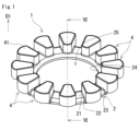
- FIG. 1 is a schematic perspective view showing an example of a core according to an embodiment.
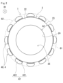
- FIG. 2 is a schematic bottom view of the core of FIG.
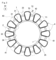
- FIG. 3 is a schematic plan view of the core of FIG.
- FIG. 4 is an enlarged view showing one of the teeth provided on the core of FIG.
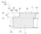
- FIG. 5 is a cross-sectional view taken along line VV of FIG.
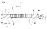
- FIG. 6 is a cross-sectional view taken along line VI-VI of FIG.
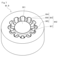
- FIG. 7 is a schematic perspective view of a die used to manufacture the core of the embodiment.
- FIG. 8 is a schematic perspective view of a lower punch used to manufacture the core of the embodiment.
- FIG. 9 is a schematic perspective view of an upper punch used to manufacture the core of the embodiment.
- FIG. 10 is a schematic top view of the cavity formed by the die of FIG. 7 and the lower punch of FIG. 8 filled with powder.
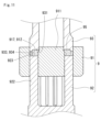
- FIG. 11 is a schematic cross-sectional view showing a part of the die of FIG. 7, the lower punch of FIG. 8, and the upper punch of FIG. 9 in a combined state.
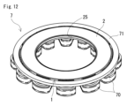
- FIG. 12 is a schematic perspective view showing an example of a stator including the core of FIG.
- FIG. 13 is a schematic perspective view showing an example of a rotating electric machine including the stator shown in FIG.
- a powder compact is produced by filling a cavity formed in a die with powder and pressurizing the filled powder. Powder is fed into the cavity using a powder box having an opening at the bottom. The powder box moves back and forth linearly on the die. When the powder box moves above the cavity, the powder in the powder box falls into the cavity from the opening of the powder box due to gravity. The bottom surface of the powder box drags some of the powder filled in the cavity as the powder box moves back and forth. Therefore, the area of the cavity near the start point of powder feeding from the powder box tends to be filled with more powder than the area near the turnaround point of powder feeding. If there is a bias in the amount of powder filled, there may be variation in the length from the back surface of the yoke to each end face of the multiple teeth in the powder compact obtained after pressurization.
- Patent Document 1 In the technology of Patent Document 1, a powder compact with the above-mentioned length variation is produced, and then grinding is performed on the end faces of each tooth in the powder compact.
- the technology of Patent Document 1 requires a grinding process, which requires a large number of steps, and there is a need to improve productivity.
- One of the objectives of this disclosure is to provide a core that has little variation in the length from the reference surface of the yoke to the end face of each of the multiple teeth and is highly manufacturable.
- the core of the present disclosure has small variation in the length from the reference surface of the yoke to the end face of each of the multiple teeth, and is highly productive.
- the yoke axis is the axis of rotational symmetry of the annular yoke. That is, the yoke axis is a straight line that passes through the center of the annular circle and is perpendicular to the first surface of the yoke.
- a powder compact is produced by filling a cavity formed in a die with powder and then pressure-molding the filled powder.
- the cavity has a shape corresponding to the core.
- the cavity has a shape in which the first surface of the yoke faces downward and the second surface faces upward.
- the second surface of the yoke is, for example, a flat surface.
- a powder box that supplies powder to the cavity moves back and forth over the powder that constitutes the second surface of the yoke.
- each tooth when the core is viewed from a first direction, each tooth does not have an area located outside the first enveloping circle formed by the outer peripheral surface of the yoke.
- the opening shape of the cavity is the shape of the yoke, that is, annular. If the opening is annular, the outline of the powder group arranged on the opening surface of the cavity is circular. If the outline of the powder group arranged on the opening surface of the cavity is circular, some of the powder is likely to be dragged by the powder box as it moves back and forth.
- each tooth when the core is viewed from the first direction, each tooth has an external region located outside the first enveloping circle formed by the outer peripheral surface of the yoke.
- the opening shape of the cavity is a shape that combines the yoke and the external region, and has an uneven contour. If the opening has an uneven contour, the powder group arranged on the opening surface of the cavity has an intermittent portion around the axis of the yoke. If there is an intermittent portion, the powder is less likely to be dragged by the powder box even when the powder box moves back and forth.
- the amount of powder filled into the cavity is less likely to be uneven. If the amount of powder filled is less likely to be uneven, the length from the reference surface of the yoke to the end surface of each of the multiple teeth is less likely to vary in the powder compact obtained after pressure molding. Therefore, in the core according to the embodiment of the present disclosure, the variation in the length from the reference surface of the yoke to the end surface of each of the multiple teeth is small.
- the core according to the embodiment of the present disclosure when the powder is pressurized to produce a powder compact, there is little variation in the length from the reference surface of the yoke to the end face of each of the multiple teeth. Therefore, after producing the powder compact, there is no need to perform grinding on the end face of each tooth. Therefore, the core according to the embodiment of the present disclosure has excellent productivity.
- the molding pressure applied to the outer region 40 by the upper punch 93 (FIG. 9) of the mold 9 is large. If the ratio of the second length L2 to the first length L1 is 60% or more and 90% or less, the above stress is easily reduced. If the ratio of the second length L2 to the first length L1 is 90% or less, the gap A1 can be provided and the wiring space according to this gap A1 can be secured. If the ratio is 60% or more, the magnetic flux that flows from the magnet 84 of the rotor 80 described below into the external area 40 can easily flow efficiently into the yoke 2. The ratio of the second length L2 to the first length L1 may be 65% or more and 85% or less, or 70% or more and 80% or less.
- the second surface 22 of the yoke 2 is used as a reference surface, and the variation in the length from this reference surface to the first end surface 41 of each of the multiple teeth 4 is small.
- the variation in the first length L1 from the second surface 22 to the first end surface 41 of each tooth 4 is 0.05 mm or less.
- the core 1 is manufactured using a powder box (not shown) that advances from the bottom to the top of the drawing in Fig. 2 and then folds back from the top to the bottom of Fig. 2. Even in this case, as shown in Fig. 6, the variation in the first length L1 of the multiple teeth 4 is 0.05 mm or less.
- the variation in the first length L1 of the multiple teeth 4 is obtained as follows. First, for each tooth 4, the first length L1 from the second surface 22 of the yoke 2 to the first end surface 41 of the tooth 4 is measured. The measurement is performed by using a height gauge equipped with a class 0 surface plate, and placing the core 1 on the surface plate so that the first end surface 41 of the tooth 4 faces upward. Multiple measurement points are selected on the first end surface 41 of each tooth 4. The measurement points are set on a straight line drawn through the center of gravity of the tooth 4 and the axis of the yoke 2. Three or more measurement points are selected on the above straight line.
- the measurement points on the above straight line include the center of gravity of the tooth 4, the edge of the tooth 4 close to the axis of the yoke 2, and the edge of the tooth 4 far from the axis of the yoke 2.
- the first length L1 of each tooth 4 is determined by measuring the length from the surface plate to each measurement point, and the average value of the lengths obtained by the measurement. Next, the maximum length and the minimum length are selected from the first lengths L1 of the multiple teeth 4.
- the variation in the first length L1 of the multiple teeth 4 is found by calculating the difference between the maximum length and the minimum length. It is preferable that the variation in the first length L1 of the multiple teeth 4 is small.
- the variation in the first length L1 of the multiple teeth 4 is, for example, 0.04 mm or less, or 0.03 mm or less.
- the core 1 is composed of a powder compact containing soft magnetic powder.
- the soft magnetic powder has a plurality of iron-based particles made of, for example, pure iron or an iron-based alloy.
- the pure iron has a purity of 99% or more, that is, the content of iron (Fe) is 99% by mass or more.
- Pure iron has the effects of high saturation magnetic flux density, excellent moldability, and easy densification by pressure molding. Therefore, when the core 1 contains iron-based particles made of pure iron, it is possible to obtain a core 1 having a high saturation magnetic flux density, a dense core 1 having a high relative density, a core 1 that is easy to mold during the manufacturing process, and a core 1 that is excellent in manufacturability.
- the iron-based alloy contains an additive element, and the remainder is made of Fe and inevitable impurities.
- the iron-based alloy contains one or more additive elements.
- the additive elements are, for example, silicon (Si), aluminum (Al), and chromium (Cr).
- the electrical resistance of the iron-based alloy is greater than that of pure iron. Therefore, when iron-based particles made of an iron-based alloy are included, iron loss such as eddy current loss can be reduced, resulting in a low-loss core 1.
- the core 1 may include both iron-based particles made of pure iron and iron-based particles made of an iron-based alloy.
- the relative density of the core 1 is, for example, 90% or more.
- a core 1 with a relative density of 90% or more has a high saturation magnetic flux density and excellent strength.
- the relative density of the core 1 may be 93% or more, or 95% or more.
- the relative density here is the ratio (%) of the actually measured density of the powder compact constituting the core 1 to the theoretical density of the powder compact constituting the core 1.
- the theoretical density can be used as an equivalent value to the true density of the soft magnetic powder constituting the powder compact.
- the relative density of the outer region 40 is higher than the relative density of any portion other than the outer region 40.
- the relative density of the outer region 40 is, for example, 93% or more, 95% or more, or 96% or more.
- the core 1 of the embodiment can be manufactured using a mold 9 shown in Figures 7 to 11.
- the mold 9 includes a die 91 shown in Figure 7, a lower punch 92 shown in Figure 8, and an upper punch 93 shown in Figure 9.
- the die 91 is a cylindrical member.
- the die 91 has a central portion 911 and an outer peripheral portion 912.
- the central portion 911 is a solid body that constitutes a central region including the axis of the die 91 and extends to both end faces of the die 91.
- the central portion 911 is for forming the axial hole 25 of the yoke 2 in the core 1.
- the outer peripheral portion 912 is located on the outer periphery of the central portion 911.
- the outer peripheral portion 912 has a recess 913 and a through hole 917 that open to the upper surface of the die 91.
- the recess 913 and the through hole 917 are arranged alternately around the axis of the die 91.
- the recess 913 has a bottom portion 914, an inner surface 915, and an outer surface 916.
- the inner surface 915 is also a side surface of the central portion 911.
- the outer surface 916 is provided to face the inner surface 915.
- the bottom portion 914 connects the inner surface 915 and the outer surface 916.
- the recess 913 is for forming the majority of the yoke 2 in the core 1.
- the bottom 914 forms the first surface 21 of the yoke 2.
- the outer surface 916 forms the outer peripheral surface 23 of the yoke 2.
- the inner surface 915 forms the inner peripheral surface 24 of the yoke 2.
- the through hole 917 penetrates the die 91 from top to bottom.
- the through hole 917 is for forming the teeth 4 in the core 1.
- the through hole 917 has the same cross-sectional shape and size as the first end surface 41 of the teeth 4.
- the envelope circle surrounding the multiple through holes 917 is larger than the envelope circle surrounding the multiple recesses 913.
- the envelope circle surrounding the multiple recesses 913 is formed by the outer surface 916 of the recesses 913.
- the contour forming the outer peripheral portion 912 is uneven.
- the lower punch 92 is inserted into the through hole 917.
- the lower punch 92 has a base 921 and multiple columnar portions 922.
- the base 921 is a cylindrical member.
- the multiple columnar portions 922 are arranged at intervals around the axis of the base 921.
- Each columnar portion 922 is inserted into a through hole 917 of the die 91.
- the end face 923 of each columnar portion 922 has the same shape and size as the first end face 41 of the tooth 4.
- the end face 923 constitutes the first end face 41 of the tooth 4.
- the upper punch 93 is a cylindrical member.
- the upper punch 93 has a first end surface 931 that is annular.
- the first end surface 931 constitutes the second surface 22 of the yoke 2.
- the upper punch 93 has a plurality of bulges 932 on its outer peripheral surface.
- the plurality of bulges 932 are arranged at intervals around the axis of the upper punch 93.
- Each bulge 932 extends along the top and bottom of the upper punch 93.
- a convex portion 934 is provided at the tip of each bulge 932.
- the convex portion 934 is provided at the location of the bulge 932 that is the furthest from the axis of the upper punch 93.
- the bulge 932 has a second end surface 933 having two surfaces that constitute a step by the convex portion 934.
- the second end surface 933 constitutes the second end surface 42 of the outer region 40 of the tooth 4.
- the surface located proximal to the first end surface 931 constitutes the proximal surface 421
- the surface located further distal from the first end surface 931 constitutes the distal surface 422.
- a cavity is formed in which powder 95 is filled.
- Powder is fed into the cavity using a powder box (not shown).
- the powder box has an opening at the bottom.
- the powder box moves back and forth linearly above the die 91.
- the powder in the powder box falls into the cavity from the opening of the powder box due to gravity.
- Figure 10 shows the state in which the cavity is filled with powder 95. After the powder 95 is filled into the cavity, the powder box is folded back. When this folding back occurs, the bottom surface of the powder box tends to drag some of the powder 95 filled in the cavity.
- the cavity opening shape has an uneven contour corresponding to the contour of the outer periphery 912 of the die 91, as shown in FIG. 10.
- the powder 95 arranged on the opening surface of the cavity has discontinuous portions around the axis of the die 91. If there are discontinuous portions, the powder 95 is less likely to be dragged by the powder box even when it moves back and forth. If the powder 95 is less likely to be dragged when the powder box moves back and forth, unevenness in the amount of powder 95 filled into the cavity is less likely to occur.
- the powder 95 is pressed by a lower punch 92 and an upper punch 93. If there is little bias in the amount of powder 95 filled into the cavity, there is little variation in the length from the second surface 22 of the yoke 2 to the first end surface 41 of each of the multiple teeth 4 in the powder compact obtained after pressure molding.
- the second end surface 42 of each tooth 4 is formed by transferring the shape of a convex portion 934 provided on the upper punch 93. If the upper punch 93 has a convex portion 934, a relatively large stress is generated at the corner between the bottom 914 and the outer surface 916 of the recess 913 provided in the die 91. This corner forms the first corner portion 31 of the yoke 2. If the second end surface 933 has a step formed by two surfaces, it is easier to reduce the above-mentioned stress generated in the die 91.
- the corners between the bottom 914 and the outer surface 916 of the recess 913 provided in the die 91, and the corners between the bottom 914 and the inner surface 915 may be rounded.
- the radius of curvature of the corners between the bottom 914 and the outer surface 916 may be larger than the radius of curvature of the angle between the bottom 914 and the inner surface 915.
- the core 1 obtained with the above-mentioned die 9 has a small variation in length from the second surface 22 of the yoke 2 to the first end surface 41 of each of the multiple teeth 4 when the powder 95 is pressurized to produce a powder compact. Therefore, after producing the powder compact, there is no need to perform grinding on the first end surface 41 of each tooth 4. Therefore, the core 1 obtained with the above-mentioned die 9 has excellent productivity.
- the rotating electric machine 8 includes a rotor 80 and a stator 7.
- the stator 7 faces the rotor 80 in a direction along the rotation axis of the rotor 80.
- the rotating electric machine 8 can be used as a motor or a generator.
- Fig. 13 is a cross-sectional view taken along a plane parallel to the rotation axis 81 of the rotating electric machine 8.
- Fig. 13 illustrates a single rotor and a double stator type in which one rotor 80 is assembled so as to be sandwiched between two stators 7.
- the rotating electric machine 8 may include one rotor 80 and one stator 7, or may include one stator 7 assembled so as to be sandwiched between two rotors 80.
- the rotating electric machine 8 of the embodiment is easy to assemble because it includes the core 1 of the embodiment.
- the core 1 has a small variation in length from the second surface 22 of the yoke 2 to the first end surface 41 of each of the multiple teeth 4. Therefore, when the stator 7 and rotor 80 are stored in the case 82, the core 1, coil 70, and rotor 80 are precisely positioned. Furthermore, because the rotating electric machine 8 of the embodiment includes the core 1 of the embodiment, torque ripple can be reduced, and noise and vibration are reduced.
Landscapes
- Engineering & Computer Science (AREA)
- Power Engineering (AREA)
- Iron Core Of Rotating Electric Machines (AREA)
Priority Applications (2)
| Application Number | Priority Date | Filing Date | Title |
|---|---|---|---|
| JP2025514863A JP7716046B1 (ja) | 2023-12-26 | 2024-11-19 | コア、および回転電機 |
| JP2025120483A JP2025134058A (ja) | 2023-12-26 | 2025-07-17 | ステータ、および回転電機 |
Applications Claiming Priority (2)
| Application Number | Priority Date | Filing Date | Title |
|---|---|---|---|
| JP2023-219625 | 2023-12-26 | ||
| JP2023219625 | 2023-12-26 |
Publications (1)
| Publication Number | Publication Date |
|---|---|
| WO2025142204A1 true WO2025142204A1 (ja) | 2025-07-03 |
Family
ID=96217380
Family Applications (1)
| Application Number | Title | Priority Date | Filing Date |
|---|---|---|---|
| PCT/JP2024/040999 Pending WO2025142204A1 (ja) | 2023-12-26 | 2024-11-19 | コア、および回転電機 |
Country Status (2)
| Country | Link |
|---|---|
| JP (2) | JP7716046B1 (https=) |
| WO (1) | WO2025142204A1 (https=) |
Families Citing this family (1)
| Publication number | Priority date | Publication date | Assignee | Title |
|---|---|---|---|---|
| KR102913123B1 (ko) * | 2024-02-20 | 2026-01-15 | 주식회사농심 | 홍조류 유래의 색소 성분을 추출하는 방법 |
Citations (2)
| Publication number | Priority date | Publication date | Assignee | Title |
|---|---|---|---|---|
| JP2020108323A (ja) * | 2018-12-28 | 2020-07-09 | 住友電気工業株式会社 | コア、ステータ、及び回転電機 |
| JP2022173587A (ja) * | 2018-10-26 | 2022-11-18 | 住友電気工業株式会社 | コア、ステータ、及び回転電機 |
-
2024
- 2024-11-19 WO PCT/JP2024/040999 patent/WO2025142204A1/ja active Pending
- 2024-11-19 JP JP2025514863A patent/JP7716046B1/ja active Active
-
2025
- 2025-07-17 JP JP2025120483A patent/JP2025134058A/ja active Pending
Patent Citations (2)
| Publication number | Priority date | Publication date | Assignee | Title |
|---|---|---|---|---|
| JP2022173587A (ja) * | 2018-10-26 | 2022-11-18 | 住友電気工業株式会社 | コア、ステータ、及び回転電機 |
| JP2020108323A (ja) * | 2018-12-28 | 2020-07-09 | 住友電気工業株式会社 | コア、ステータ、及び回転電機 |
Also Published As
| Publication number | Publication date |
|---|---|
| JPWO2025142204A1 (https=) | 2025-07-03 |
| JP2025134058A (ja) | 2025-09-11 |
| JP7716046B1 (ja) | 2025-07-31 |
Similar Documents
| Publication | Publication Date | Title |
|---|---|---|
| JP7524419B2 (ja) | コア、ステータ、及び回転電機 | |
| JP7195920B2 (ja) | コア、ステータ、及び回転電機 | |
| JP7572411B2 (ja) | コア、ステータ、及び回転電機 | |
| JP7716046B1 (ja) | コア、および回転電機 | |
| JP2025039857A (ja) | 部材、ステータコア、ステータ、および回転電機 | |
| JP7749075B2 (ja) | 回転電機 | |
| WO2022270135A1 (ja) | ステータコア、ステータ、回転電機、及びステータコアの製造方法 | |
| JP7362656B2 (ja) | コア、ステータ、及び回転電機 | |
| US11791672B2 (en) | Core, stator, and rotating electric machine | |
| JP2021100329A (ja) | ステータコア、ステータ、回転電機、及びステータコアの製造方法 | |
| WO2024019077A1 (ja) | コア片、ステータコア、ステータ、及び回転電機 | |
| WO2026053493A1 (ja) | コア片、およびアキシャルギャップ型の回転電機 |
Legal Events
| Date | Code | Title | Description |
|---|---|---|---|
| ENP | Entry into the national phase |
Ref document number: 2025514863 Country of ref document: JP Kind code of ref document: A |
|
| WWE | Wipo information: entry into national phase |
Ref document number: 2025514863 Country of ref document: JP |
|
| 121 | Ep: the epo has been informed by wipo that ep was designated in this application |
Ref document number: 24912097 Country of ref document: EP Kind code of ref document: A1 |