WO2025142148A1 - 動力変換装置 - Google Patents
動力変換装置 Download PDFInfo
- Publication number
- WO2025142148A1 WO2025142148A1 PCT/JP2024/039779 JP2024039779W WO2025142148A1 WO 2025142148 A1 WO2025142148 A1 WO 2025142148A1 JP 2024039779 W JP2024039779 W JP 2024039779W WO 2025142148 A1 WO2025142148 A1 WO 2025142148A1
- Authority
- WO
- WIPO (PCT)
- Prior art keywords
- gear
- axis
- output member
- driving force
- way clutch
- Prior art date
- Legal status (The legal status is an assumption and is not a legal conclusion. Google has not performed a legal analysis and makes no representation as to the accuracy of the status listed.)
- Pending
Links
Images


Classifications
-
- B—PERFORMING OPERATIONS; TRANSPORTING
- B62—LAND VEHICLES FOR TRAVELLING OTHERWISE THAN ON RAILS
- B62K—CYCLES; CYCLE FRAMES; CYCLE STEERING DEVICES; RIDER-OPERATED TERMINAL CONTROLS SPECIALLY ADAPTED FOR CYCLES; CYCLE AXLE SUSPENSIONS; CYCLE SIDECARS, FORECARS, OR THE LIKE
- B62K5/00—Cycles with handlebars, equipped with three or more main road wheels
- B62K5/02—Tricycles
-
- B—PERFORMING OPERATIONS; TRANSPORTING
- B62—LAND VEHICLES FOR TRAVELLING OTHERWISE THAN ON RAILS
- B62M—RIDER PROPULSION OF WHEELED VEHICLES OR SLEDGES; POWERED PROPULSION OF SLEDGES OR SINGLE-TRACK CYCLES; TRANSMISSIONS SPECIALLY ADAPTED FOR SUCH VEHICLES
- B62M1/00—Rider propulsion of wheeled vehicles
- B62M1/24—Rider propulsion of wheeled vehicles with reciprocating levers, e.g. foot levers
- B62M1/26—Rider propulsion of wheeled vehicles with reciprocating levers, e.g. foot levers characterised by rotary cranks combined with reciprocating levers
-
- B—PERFORMING OPERATIONS; TRANSPORTING
- B62—LAND VEHICLES FOR TRAVELLING OTHERWISE THAN ON RAILS
- B62M—RIDER PROPULSION OF WHEELED VEHICLES OR SLEDGES; POWERED PROPULSION OF SLEDGES OR SINGLE-TRACK CYCLES; TRANSMISSIONS SPECIALLY ADAPTED FOR SUCH VEHICLES
- B62M17/00—Transmissions characterised by use of rotary shaft, e.g. cardan shaft
-
- F—MECHANICAL ENGINEERING; LIGHTING; HEATING; WEAPONS; BLASTING
- F16—ENGINEERING ELEMENTS AND UNITS; GENERAL MEASURES FOR PRODUCING AND MAINTAINING EFFECTIVE FUNCTIONING OF MACHINES OR INSTALLATIONS; THERMAL INSULATION IN GENERAL
- F16H—GEARING
- F16H31/00—Other gearings with freewheeling members or other intermittently driving members
Definitions
- the present invention relates to a power conversion device that converts a driving force input as a reciprocating oscillation into a unidirectional rotational driving force and outputs it.
- Patent Document 1 JP 2008-018885 A discloses a power conversion device that transmits human force applied to a pedal (18) to a pedal pulley (24) via a crank arm (21) and a belt (25), and then transmits the force from the pedal pulley (24) to the rear wheel (19), which is the driving wheel, via a differential gear unit (70).
- the differential gears (65a, 65b) in the differential gear unit (70) are held in a differential gear box (60) via one-way clutch bearings (66a, 66b), thereby realizing a structure that converts the driving force input as a reciprocating oscillation into a one-way rotational driving force.
- the left and right crank arms are connected by a belt to allow the pedals to rotate in the opposite direction, and the driving force transmitted from this belt to the pedal pulley is converted into a one-way rotational driving force using a differential gear and a one-way clutch bearing.
- the power conversion device of Patent Document 1 has a complex structure, which can lead to problems such as a large number of parts.
- the power conversion device comprises a first gear and a second gear which are a pair of gears supported to be rotatable about a first axis, a third gear and a fourth gear which are a pair of gears supported to be rotatable about a second axis which intersects the first axis when viewed in a first direction perpendicular to the first axis, a first input member which transmits a driving force to the first gear, a second input member which transmits a driving force to the second gear, an output member supported to be rotatable about the second axis, a first one-way clutch, and a second one-way clutch, wherein the first gear and the second gear are disposed on opposite sides of the second axis when viewed in the first direction, the third gear meshes with both the first gear and the second gear, and the fourth gear is disposed in a front-to-rear direction.
- the first one-way clutch is disposed on the opposite side of the third gear across the first axis when viewed in the first direction, meshes with both the first gear and the second gear, and has one side of the rotation direction around the second axis as the first rotation side and the other side as the second rotation side.
- the first one-way clutch is provided in a power transmission path between the third gear and the output member, and is configured to restrict the relative rotation of the first rotation side of the third gear with respect to the output member and allow the relative rotation of the second rotation side.
- the second one-way clutch is provided in a power transmission path between the fourth gear and the output member, and is configured to restrict the relative rotation of the first rotation side of the fourth gear with respect to the output member and allow the relative rotation of the second rotation side.
- the first gear and the second gear rotate in opposite directions, when a state in which a driving force that rotates the first gear in one direction is input to the first input member and a state in which a driving force that rotates the second gear in the same direction is input to the second input member alternately occur, the first gear and the second gear are oscillated back and forth by these driving forces, and the driving force of this reciprocating oscillation can be converted into a unidirectional rotational driving force of the output member via the third gear and the first one-way clutch, and the fourth gear and the second one-way clutch, and output. Therefore, it is easy to make a power conversion device that converts the driving force input as a reciprocating oscillation into a unidirectional rotational driving force and outputs it with a simple structure.
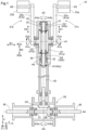
- FIG. 1 is a top view showing an example of a power conversion device in a state in which a first gear rotates toward a first input rotation side
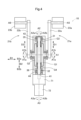
- FIG. 1 is a top view showing an example of a power conversion device in a state in which a first gear rotates toward a second input rotation side
- FIG. 2 is a side view showing an example of a vehicle equipped with the power conversion device of FIG.
- FIG. 1 is a top view showing an example of a power generating device including a power conversion device;
- FIG. 1 is a top view of the power conversion device 10.
- the power conversion device 10 includes a first gear G1 and a second gear G2.
- the first gear G1 and the second gear G2 are a pair of gears supported to be rotatable around a first axis A1.
- the first gear G1 and the second gear G2 are supported by a non-rotating member. Examples of the "non-rotating member" include a case, a housing, a frame, etc.
- the first gear G1 and the second gear G2 are arranged on opposite sides of the second axis A2 when viewed in a first direction perpendicular to the first axis A1.
- the first direction is the vertical direction Z, but the first direction may be a direction different from the vertical direction Z.
- the direction along the first axis A1 is defined as the first axis direction B1.
- the first gear G1 and the second gear G2 are arranged so that their gear teeth face each other in the first axis direction B1, but the gear teeth do not have to face each other in the first axial direction B1.
- the power conversion device 10 includes a first input member 21a that transmits a driving force to the first gear G1.
- the first input member 21a includes a first crank member 22a that is disposed so as to extend in a direction perpendicular to the first axis A1.
- the first crank member 22a is connected so as to rotate integrally with the first gear G1.
- a first input axis A5 is set at a position in the first crank member 22a that is spaced apart from the first axis A1.
- the first input member 21a includes a first pedal 23a.
- the first pedal 23a is connected to the first crank member 22a so as to be rotatable around the first input axis A5 relative to the first crank member 22a.
- the first axis A1 and the first input axis A5 are parallel to each other, but they do not have to be parallel to each other.
- the power conversion device 10 includes a second input member 21b that transmits a driving force to the second gear G2.
- the second input member 21b includes a second crank member 22b that is disposed so as to extend in a direction perpendicular to the first axis A1.
- the second crank member 22b is connected to the second gear G2 so as to rotate integrally with the second gear G2.
- a second input axis A6 is set at a position in the second crank member 22b that is spaced apart from the first axis A1.
- the second input member 21b includes a second pedal 23b.
- the second pedal 23b is connected to the second crank member 22b so as to be rotatable around the second input axis A6 relative to the second crank member 22b.
- the first axis A1 and the second input axis A6 are parallel, but they do not have to be parallel.
- extending in a certain direction does not mean that the direction is a reference direction and the extending direction of the member is parallel to the reference direction, but may be a direction in which the extending direction of the whole or part of the member intersects the reference direction, and is used as a concept including a shape in which the extending direction of the whole member is within a predetermined range with respect to the reference direction, for example, 60 degrees or less, 45 degrees or less, 20 degrees or less, 10 degrees or less, etc.
- the extending direction of the first crank member 22a is the first radial direction D1
- the extending direction of the second crank member 22b is the second radial direction D2.
- first crank member 22a and the second crank member 22b are arranged so that there is a phase in which the first radial direction D1 and the second radial direction D2 are parallel to each other, but there does not have to be a phase in which they are parallel to each other.
- the power conversion device 10 includes a pair of gears, a third gear G3 and a fourth gear G4, supported for free rotation around a second axis A2.
- the second axis A2 intersects with the first axis A1 when viewed in a first direction perpendicular to the first axis A1.
- the second axis A2 and the first axis A1 are perpendicular to each other when viewed in the first direction.
- the second axis A2 and the first axis A1 have an intersection.
- one side of the direction of rotation around the first axis A1 is the first input rotation side A1a
- the other side is the second input rotation side A1b.
- the third gear G3 meshes with both the first gear G1 and the second gear G2.
- the fourth gear G4 meshes with both the first gear G1 and the second gear G2.
- the second gear G2 is disposed on the opposite side of the first gear G1 across the second axis A2 when viewed in the first direction.
- the fourth gear G4 is disposed on the opposite side of the first axis A1 across the third gear G3 when viewed in the first direction.
- the direction along the second axis A2 is defined as the second axis direction B2.
- One side of the direction of rotation around the second axis A2 is defined as the first rotation side A2a, and the other side is defined as the second rotation side A2b.
- the number of teeth of the first gear G1 is the same as the number of teeth of the second gear G2.
- the number of teeth of the third gear G3 is the same as the number of teeth of the fourth gear G4.
- the number of teeth of the first gear G1 is greater than the number of teeth of the third gear G3.
- the number of teeth of the second gear G2 is greater than the number of teeth of the fourth gear G4.
- Examples of the first gear G1 to the fourth gear G4 include straight bevel gears, spiral bevel gears, face gears, hypoid gears (registered trademark), etc.
- the power conversion device 10 includes a first one-way clutch 31, a second one-way clutch 32, and an output member 41 supported for free rotation about the third axis A3.
- one side of the direction of rotation about the third axis A3 is the first output rotation side A3a
- the other side is the second output rotation side A3b.
- the second axis A2 and the third axis A3 are parallel when viewed in the first direction, but they do not have to be parallel.
- the second axis A2 and the third axis A3 are the same axis. Therefore, the first rotation side A2a and the first output rotation side A3a are the same, and the second rotation side A2b and the second output rotation side A3b are the same.
- the first one-way clutch 31 is provided in the power transmission path between the third gear G3 and the output member 41.
- the first one-way clutch 31 is configured to rotate the output member 41 to the first output rotation side A3a when the third gear G3 rotates to the first rotation side A2a, and to rotate the third gear G3 idly with respect to the output member 41 when the third gear G3 rotates to the second rotation side A2b.
- the first one-way clutch 31 is configured to restrict the relative rotation of the first rotation side A2a of the third gear G3 with respect to the output member 41, and to allow the relative rotation of the second rotation side A2b.
- the second one-way clutch 32 is provided in the power transmission path between the fourth gear G4 and the output member 41.
- the second one-way clutch 32 is configured to rotate the output member 41 to the first output rotation side A3a when the fourth gear G4 rotates to the first rotation side A2a, and to rotate the fourth gear G4 idly with respect to the output member 41 when the fourth gear G4 rotates to the second rotation side A2b.
- the second one-way clutch 32 is configured to restrict the relative rotation of the first rotation side A2a of the fourth gear G4 with respect to the output member 41, and to allow the relative rotation of the second rotation side A2b.
- the third gear G3 is connected to the first outer wheel support portion 35, which supports one of the outer wheel or inner wheel of the first one-way clutch 31, so as to rotate integrally with it.
- the other of the outer wheel or inner wheel of the first one-way clutch 31 is supported by the output member 41.
- the first outer wheel support portion 35 is a cylindrical member, and the outer wheel of the first one-way clutch 31 is disposed on its inner circumferential surface.
- the fourth gear G4 is connected to the second outer wheel support portion 36, which supports one of the outer wheel or inner wheel of the second one-way clutch 32, so as to rotate integrally with the second outer wheel support portion 36.
- the other of the outer wheel or inner wheel of the second one-way clutch 32 is supported by the output member 41.
- the second outer wheel support portion 36 is a cylindrical member, and the outer wheel of the second one-way clutch 32 is disposed on its inner circumferential surface.
- rotate integrally refers to a state in which two members or two parts are connected so that they always rotate at the same speed. This includes a configuration in which two parts are integrally formed from the same member, and a configuration in which two separate members are connected so that they rotate integrally.
- the first gear G1 rotates to the first input rotation side A1a
- the third gear G3 rotates to the first rotation side A2a
- the fourth gear G4 rotates to the second rotation side A2b.
- the first one-way clutch 31 is configured to transmit the rotational driving force of the first rotation side A2a of the third gear G3 to the output member 41.
- the second one-way clutch 32 is configured not to transmit the rotational driving force of the second rotation side A2b of the fourth gear G4 to the output member 41.
- the third gear G3 rotates to the second rotation side A2b
- the fourth gear G4 rotates to the first rotation side A2a.
- the first one-way clutch 31 is configured not to transmit the rotational driving force of the second rotation side A2b of the third gear G3 to the output member 41.
- the second one-way clutch 32 is configured to transmit the rotational driving force of the first rotation side A2a of the fourth gear G4 to the output member 41.
- the output member 41 is formed in an axial shape and passes through the third gear G3 and the fourth gear G4.
- the third gear G3 is disposed between the first gear G1 and the second gear G2 in the first axial direction B1.
- the fourth gear G4 is disposed between the first gear G1 and the second gear G2 in the first axial direction B1.
- the output member 41 is disposed so that it has a portion sandwiched between the first gear G1 and the second gear G2 in the first axial direction B1.
- the direction along the first axis A1 is the first axis direction B1
- the direction along the second axis A2 is the second axis direction B2.
- the side of the second axis direction B2 where the third gear G3 is located relative to the fourth gear G4 is the second axis direction first side B2a
- the opposite side is the second axis direction second side B2b.
- the power conversion device 10 includes a first bearing 43.
- the first bearing 43 supports a portion of the output member 41 that is closer to the first side B2a in the second axial direction than the third gear G3.
- the power conversion device 10 includes a second bearing 44.
- the second bearing 44 supports a portion of the output member 41 that is closer to the second side B2b in the second axial direction than the fourth gear G4.
- FIG. 3 is a side view showing a vehicle 60 equipped with a power conversion device 10.
- a portion of the body 61 of the vehicle 60 is cut away to show the power conversion device 10.
- the power conversion device 10 is mounted on the vehicle 60, which is equipped with wheels 66.
- Examples of the vehicle 60 include two-wheeled vehicles, four-wheeled vehicles, track bicycles, water bicycles, ice bicycles, mopeds, and motorcycles.
- the vehicle 60 is a three-wheeled bicycle.
- the front-rear direction of the vehicle 60 is referred to as the front-rear direction X
- the width direction of the vehicle 60 is referred to as the width direction Y
- the up-down direction of the vehicle 60 is referred to as the up-down direction Z.
- the wheels 66 and the axles 65 are arranged in pairs, spaced apart in the width direction Y of the vehicle 60.
- the above-mentioned first axis direction B1 is parallel to the width direction Y.
- the above-mentioned second axis direction B2 is parallel to the front-rear direction X.
- both the first pedal 23a and the second pedal 23b are arranged so that they are always above the first axis center A1, Z1.
- the driving force transmitted from the output member 41 to the wheels 66 in a direction that accelerates the vehicle 60 is defined as the acceleration driving force
- the driving force transmitted from the output member 41 to the wheels 66 in a direction that decelerates the vehicle 60 is defined as the deceleration driving force
- the power conversion device 10 includes a power transmission mechanism 50 that transmits driving force between the output member 41 and the wheels 66.
- the power transmission mechanism 50 includes a third one-way clutch 51.
- the third one-way clutch 51 is configured to transmit acceleration driving force but not deceleration driving force.
- the power transmission mechanism 50 transmits driving force to the rear wheels 66.
- the power transmission mechanism 50 includes a fifth gear G5 and a sixth gear G6 that meshes with the fifth gear G5.
- the fifth gear G5 is configured to transmit at least the acceleration driving force from the output member 41.
- the fifth gear G5 and the output member 41 are connected to rotate integrally, but they do not have to rotate integrally.
- the output member 41 and the fifth gear G5 are connected via an intermediate shaft member 42.
- the sixth gear G6 transmits the acceleration driving force to the wheels 66 via the axles 65.
- the sixth gear G6 is disposed between a pair of axles 65 in the width direction Y of the vehicle 60.
- the wheels 66 and the axles 65 rotate around the fourth axis A4.
- the sixth gear G6 rotates around the fourth axis A4.
- the third one-way clutch 51 is provided in the power transmission path between the sixth gear G6 and the axles 65.
- the third one-way clutch 51 is provided in each of the power transmission path between the sixth gear G6 and one axle 65 and the power transmission path between the sixth gear G6 and the other axle 65.
- the fourth axis A4 is parallel to the first axis A1, but it does not have to be parallel.
- the power transmission mechanism 50 is configured so that when the first pedal 23a moves away from the seat 67 of the vehicle 60 and the first gear G1 rotates to the first input rotation side A1a, the vehicle 60 moves forward.
- the first crank member 22a is arranged so that when the first pedal 23a approaches the seat 67 of the vehicle 60, the first gear G1 rotates to the second input rotation side A1b.
- the power transmission mechanism 50 is configured so that when the second pedal 23b moves away from the seat 67 of the vehicle 60 and the second gear G2 rotates to the first input rotation side A1a, the vehicle 60 moves forward.
- the second crank member 22b is arranged so that when the second pedal 23b approaches the seat 67 of the vehicle 60, the second gear G2 rotates to the second input rotation side A1b.
- the power conversion device 10 is mounted on a vehicle 60.
- the present invention is not limited to such an example, and for example, the power conversion device 10 may be provided in a power generation device as shown in FIG. 4.
- the power generation device shown in FIG. 4 includes a speed increaser 71 and a rotating electric machine 72, and the driving force output from the output member 41 of the power conversion device 10 is input to the speed increaser 71.
- the number of teeth of the first gear G1 and the second gear G2 is greater than the number of teeth of the third gear G3 and the fourth gear G4.
- the number of teeth of the first gear G1 and the second gear G2 may be the same as or less than the number of teeth of the third gear G3 and the fourth gear G4.
- the number of teeth of the first gear G1 and the number of teeth of the second gear G2 may be different.
- the number of teeth of the third gear G3 and the number of teeth of the fourth gear G4 may be different.
- the output member 41 is disposed so as to penetrate the third gear G3 and the fourth gear G4 and to have a portion sandwiched between the first gear G1 and the second gear G2 in the first axial direction B1.
- the present invention is not limited to such an example, and may be configured such that the output member 41 penetrates only one of the third gear G3 and the fourth gear G4.
- the first one-way clutch 31 may be provided between the gear meshing with the third gear G3 and the output member 41.
- the second one-way clutch 32 may be provided between the gear meshing with the fourth gear G4 and the output member 41.
- the output member 41 may not have a portion sandwiched between the first gear G1 and the second gear G2 in the first axial direction B1.
- the present invention is not limited to such an example, and may be configured, for example, such that the first input member 21a does not include the first crank member 22a or the first pedal 23a. Also, for example, the second input member 21b may not include the second crank member 22b or the second pedal 23b.
- the power conversion device 10 includes a power transmission mechanism 50 having a third one-way clutch 51.
- the present invention is not limited to such an example, and for example, the power transmission mechanism 50 does not need to include the third one-way clutch 51.
- the first axis A1 and the second axis A2 have an intersection and are perpendicular when viewed in the first direction.
- the present invention is not limited to such an example, and for example, the second axis A2 and the first axis A1 do not have to have an intersection. Also, for example, the first axis A1 and the second axis A2 do not have to be perpendicular when viewed in the first direction. Also, for example, the first axis A1 and the second axis A2 do not have to be perpendicular.
- the power conversion device 10 is described as having a first bearing 43, a second bearing 44, and a power transmission mechanism 50.
- the present invention is not limited to such an example, and for example, the power conversion device 10 may not have any or all of the first bearing 43, the second bearing 44, and the power transmission mechanism 50.
- the power conversion device (10) includes a first gear (G1) and a second gear (G2) that are a pair of gears supported to be freely rotatable around a first axis (A1), a third gear (G3) and a fourth gear (G4) that are a pair of gears supported to be freely rotatable around a second axis (A2) that intersects with the first axis (A1) when viewed in a first direction perpendicular to the first axis (A1), a first input member (21a) that transmits a driving force to the first gear (G1), and a second gear (G2) that is a pair of gears supported to be freely rotatable around a second axis (A2) that intersects with the first axis (A1) when viewed in a first direction perpendicular to the first axis (A1).
- a first input member (21a) that transmits a driving force to the first gear (G1)
- a second gear (G2) that is a pair
- the second input member (21b) that transmits a driving force to the second gear (G2)
- an output member (41) supported so as to be rotatable about a second axis (A2), a first one-way clutch (31), and a second one-way clutch (32)
- the first gear (G1) and the second gear (G2) being disposed on opposite sides of the second axis (A2) when viewed in the first direction
- the third gear (G3) meshes with both the first gear (G1) and the second gear (G2)
- the fourth gear (G4) is disposed on the opposite side of the third gear (G3) across the first axis (A1) when viewed in the first direction, and meshes with both the first gear (G1) and the second gear (G2).
- the first one-way clutch (31) is provided in a power transmission path between the third gear (G3) and the output member (41), and the fourth gear (G4) is disposed on the opposite side of the direction of rotation around the second axis (A2) as the first rotation side (A2a) and the other side is the second rotation side (A2b).
- the second one-way clutch (32) is provided in the power transmission path between the fourth gear (G4) and the output member (41) and is configured to restrict the relative rotation of the first rotating side (A2a) of the fourth gear (G4) to the output member (41) and allow the relative rotation of the second rotating side (A2b).
- the first gear (G1) and the second gear (G2) rotate in opposite directions, when a state in which a driving force for rotating the first gear (G1) in one direction is input to the first input member (21a) and a state in which a driving force for rotating the second gear (G2) in the same direction is input to the second input member (21b) alternately occur, the first gear (G1) and the second gear (G2) are reciprocally oscillated by these driving forces, and the driving force of the reciprocating oscillation can be converted and outputted into a one-way rotational driving force of the output member (41) via the third gear (G3) and the first one-way clutch (31) and the fourth gear (G4) and the second one-way clutch (32). Therefore, it is easy to make the power conversion device (10) that converts the driving force inputted as a reciprocating oscillation into a one-way rotational driving force and outputs it into a simple structure.
- the number of teeth of the first gear (G1) is the same as the number of teeth of the second gear (G2)
- the number of teeth of the third gear (G3) is the same as the number of teeth of the fourth gear (G4)
- the number of teeth of the first gear (G1) and the second gear (G2) is greater than the number of teeth of the third gear (G3) and the fourth gear (G4).
- the direction along the first axis (A1) is defined as the first axis direction (B1)
- the output member (41) is formed in a shaft shape, and is disposed so as to penetrate the third gear (G3) and the fourth gear (G4) and have a portion sandwiched between the first gear (G1) and the second gear (G2) in the first axis direction (B1)
- the direction along the second axis (A2) is defined as the second axis direction (B2)
- the direction along the second axis (A2) is defined as the second axis direction (B2) with respect to the fourth gear (G4) in the second axis direction (B2).
- the side where the third gear (G3) is arranged is the second axial first side (B2a), and the opposite side is the second axial second side (B2b).
- the power conversion device (10) is equipped with a first bearing (43) that supports a portion of the output member (41) that is closer to the second axial first side (B2a) than the third gear (G3), and a second bearing (44) that supports a portion of the output member (41) that is closer to the second axial second side (B2b) than the fourth gear (G4).
- the output member (41) can be properly supported, and the output member (41) can properly support the third gear (G3) and the fourth gear (G4).
- the first input member (21a) is arranged to extend in a direction perpendicular to the first axis (A1) and includes a first crank member (22a) connected to the first gear (G1) so as to rotate integrally with the first gear (G1); a first input axis (A5) is set at a position in the first crank member (22a) spaced apart from the first axis (A1); and a first pedal (23a) connected to the first crank member (22a) so as to be freely rotatable around the first input axis (A5) relative to the first crank member (22a);
- the second input member (21b) is arranged to extend in a direction perpendicular to the first axis (A1) and includes a second crank member (22b) connected to the second gear (G2) so as to rotate integrally with the second gear (G2), and a second input axis (A6) is set at a position in the second crank member (22b) spaced apart from the first axis (A1),
- the power conversion device (10) is mounted on a vehicle (60) equipped with wheels (66) and further includes a power transmission mechanism (50) that transmits driving force between the output member (41) and the wheels (66).
- the power transmission mechanism (50) includes a third one-way clutch (51).
- the driving force transmitted from the output member (41) to the wheels (66) in a direction that accelerates the vehicle (60) is defined as an acceleration driving force
- the driving force transmitted from the output member (41) to the wheels (66) in a direction that decelerates the vehicle (60) is defined as a deceleration driving force.
- the third one-way clutch (51) is configured to transmit the acceleration driving force but not to transmit the deceleration driving force.
- the acceleration driving force for accelerating the vehicle (60) while the vehicle (60) is moving forward can be appropriately transmitted to the wheels (66), and the vehicle (60) can be allowed to move forward by inertia even when the driving force is not transmitted to the first input member (21a) and the second input member (21b). Therefore, it becomes easy to run the vehicle (60) efficiently.
- the power conversion device according to the present disclosure is required to achieve at least one of the effects described above.
Landscapes
- Engineering & Computer Science (AREA)
- Mechanical Engineering (AREA)
- Chemical & Material Sciences (AREA)
- Combustion & Propulsion (AREA)
- Transportation (AREA)
- General Engineering & Computer Science (AREA)
- Automatic Cycles, And Cycles In General (AREA)
- Transmission Devices (AREA)
- Gear Transmission (AREA)
Abstract
第1ギヤ(G1)に駆動力を伝達する第1入力部材(21a)と、第2ギヤ(G2)に駆動力を伝達する第2入力部材(21b)と、第3ギヤ(G3)と、第4ギヤ(G4)と、出力部材(41)と、第1ワンウェイクラッチ(31)と、第2ワンウェイクラッチ(32)と、を備え、第1ワンウェイクラッチ(31)は、第3ギヤ(G3)と出力部材(41)との動力伝達経路に設けられ、出力部材(41)に対する第3ギヤ(G3)の第1回転側(A2a)の相対回転を規制し、第2回転側(A2b)の相対回転を許容するように構成され、第2ワンウェイクラッチ(32)は、第4ギヤ(G4)と出力部材(41)との動力伝達経路に設けられ、出力部材(41)に対する第4ギヤ(G4)の第1回転側(A2a)の相対回転を規制し、第2回転側(A2b)の相対回転を許容するように構成されている。
Description
本発明は、往復揺動として入力された駆動力を一方向の回転駆動力に変換して出力する動力変換装置に関する。
特開2008-018885号公報(特許文献1)には、ペダル(18)に加えられた人力踏力をクランクアーム(21)及びベルト(25)を介してペダルプーリ(24)へと伝え、そのペダルプーリ(24)から差動歯車部(70)を介して駆動輪である後輪(19)に伝える動力変換装置が開示されている。また、差動歯車部(70)において差動歯車(65a、65b)が一方向クラッチベアリング(66a、66b)を介して差動歯車箱(60)に保持されることで、往復揺動として入力された駆動力を一方向の回転駆動力に変換する構造を実現している。
特許文献1の動力変換装置では、ペダルの反転のために左右のクランクアームがベルトで連結され、このベルトからペダルプーリに伝えられた駆動力を、差動歯車及び一方向クラッチベアリングを用いて一方向の回転駆動力に変換している。このため、特許文献1の動力変換装置は、構造が複雑であり、これに起因して例えば部品の数が多くなり易い等の問題があった。
そこで、簡素な構造とし易い動力変換装置の実現が望まれる。
本開示に係る動力変換装置は、第1軸心回りに回転自在に支持された一対のギヤである第1ギヤ及び第2ギヤと、前記第1軸心に直交する第1方向視で前記第1軸心に交差する第2軸心回りに回転自在に支持された一対のギヤである第3ギヤ及び第4ギヤと、前記第1ギヤに駆動力を伝達する第1入力部材と、前記第2ギヤに駆動力を伝達する第2入力部材と、前記第2軸心回りに回転自在に支持された出力部材と、第1ワンウェイクラッチと、第2ワンウェイクラッチと、を備え、前記第1ギヤと前記第2ギヤとは、互いに前記第1方向視で前記第2軸心を挟んだ反対側に配置され、前記第3ギヤは、前記第1ギヤと前記第2ギヤとの双方に噛み合い、前記第4ギヤは、前記第1方向視で前記第3ギヤに対して前記第1軸心を挟んだ反対側に配置され、前記第1ギヤと前記第2ギヤとの双方に噛み合い、前記第2軸心回りの回転の向きのうちの一方側を第1回転側、他方側を第2回転側として、前記第1ワンウェイクラッチは、前記第3ギヤと前記出力部材との動力伝達経路に設けられ、前記出力部材に対する前記第3ギヤの前記第1回転側の相対回転を規制し、前記第2回転側の相対回転を許容するように構成され、前記第2ワンウェイクラッチは、前記第4ギヤと前記出力部材との動力伝達経路に設けられ、前記出力部材に対する前記第4ギヤの前記第1回転側の相対回転を規制し、前記第2回転側の相対回転を許容するように構成されている。
本構成によれば、第1ギヤと第2ギヤとが互いに反対側に回転するため、第1ギヤを一方側に回転させる駆動力が第1入力部材に入力される状態と、第2ギヤを同じ側に回転させる駆動力が第2入力部材に入力される状態とが交互に発生するような場合に、それらの駆動力によって第1ギヤと第2ギヤとを往復揺動させ、当該往復揺動の駆動力を第3ギヤ及び第1ワンウェイクラッチと第4ギヤ及び第2ワンウェイクラッチとを介して、出力部材の一方向の回転駆動力に変換して出力することができる。従って、往復揺動として入力された駆動力を一方向の回転駆動力に変換して出力する動力変換装置を、簡素な構造とし易い。
以下、動力変換装置の実施形態について図面を参照して説明する。
図1は、動力変換装置10の上面図である。動力変換装置10は、第1ギヤG1及び第2ギヤG2を備えている。第1ギヤG1及び第2ギヤG2は、第1軸心A1回りに回転自在に支持された一対のギヤである。第1ギヤG1及び第2ギヤG2は、非回転部材に支持されている。「非回転部材」の例としては、ケース、ハウジング、フレーム、等が挙げられる。第1ギヤG1と第2ギヤG2とは、互いに第1軸心A1に直交する第1方向視で第2軸心A2を挟んだ反対側に配置されている。本実施形態では、第1方向が上下方向Zであるが、第1方向が上下方向Zと異なる方向であってもよい。
ここで、第1軸心A1に沿う方向を第1軸方向B1とする。本実施形態では、第1ギヤG1と第2ギヤG2とは、互いのギヤ歯が第1軸方向B1に対向するように配置されているが、互いのギヤ歯が第1軸方向B1に対向しなくてもよい。
動力変換装置10は、第1ギヤG1に駆動力を伝達する第1入力部材21aを備えている。第1入力部材21aは、第1軸心A1に直交する方向に延在するように配置された第1クランク部材22aを備えている。第1クランク部材22aは、第1ギヤG1と一体的に回転するように連結されている。第1クランク部材22aにおける第1軸心A1から離間した位置には、第1入力軸心A5が設定されている。第1入力部材21aは、第1ペダル23aを備えている。第1ペダル23aは、第1クランク部材22aに対して第1入力軸心A5回りに回転自在に第1クランク部材22aに連結されている。本実施形態では、第1軸心A1と第1入力軸心A5とが平行であるが、平行でなくてもよい。
動力変換装置10は、第2ギヤG2に駆動力を伝達する第2入力部材21bを備えている。第2入力部材21bは、第1軸心A1に直交する方向に延在するように配置された第2クランク部材22bを備えている。第2クランク部材22bは、第2ギヤG2と一体的に回転するように連結されている。第2クランク部材22bにおける第1軸心A1から離間した位置には、第2入力軸心A6が設定されている。第2入力部材21bは、第2ペダル23bを備えている。第2ペダル23bは、第2クランク部材22bに対して第2入力軸心A6回りに回転自在に第2クランク部材22bに連結されている。本実施形態では、第1軸心A1と第2入力軸心A6とが平行であるが、平行でなくてもよい。
ここで、部材の形状に関し、「ある方向に延在する」とは、当該方向を基準方向として、部材の延在方向が前記基準方向に平行な形状に限らず、部材の全体又は一部の延在方向が前記基準方向に交差する方向となっていてもよく、部材の全体としての延在方向が前記基準方向に対して予め定められた範囲内、例えば60度以下、45度以下、20度以下、10度以下、等である形状も含む概念として用いている。ここで、第1クランク部材22aの延在方向を第1径方向D1とし、第2クランク部材22bの延在方向を第2径方向D2とする。本実施形態では、第1径方向D1と第2径方向D2とが互いに平行となる位相が存在するように、第1クランク部材22aと第2クランク部材22bとが配置されているが、互いに平行となる位相が存在しなくてもよい。
動力変換装置10は、第2軸心A2回りに回転自在に支持された一対のギヤである第3ギヤG3及び第4ギヤG4を備えている。第2軸心A2は、第1軸心A1に直交する第1方向視で第1軸心A1に交差する。図示の例では、第2軸心A2と第1軸心A1とが第1方向視で直交する。本実施形態では、第2軸心A2と第1軸心A1とが交点を有している。ここで、第1軸心A1回りの回転の向きのうちの一方側を第1入力回転側A1aとし、他方側を第2入力回転側A1bとする。
第3ギヤG3は、第1ギヤG1と第2ギヤG2との双方に噛み合う。第4ギヤG4は、第1ギヤG1と第2ギヤG2との双方に噛み合う。第2ギヤG2は、第1方向視で第1ギヤG1に対して第2軸心A2を挟んだ反対側に配置されている。第4ギヤG4は、第1方向視で第3ギヤG3に対して第1軸心A1を挟んだ反対側に配置されている。ここで、第2軸心A2に沿う方向を第2軸方向B2とする。第2軸心A2回りの回転の向きのうちの一方側を第1回転側A2aとし、他方側を第2回転側A2bとする。
第1ギヤG1の歯数は、第2ギヤG2の歯数と同じである。第3ギヤG3の歯数は、第4ギヤG4の歯数と同じである。第1ギヤG1の歯数は、第3ギヤG3の歯数よりも多い。第2ギヤG2の歯数は、第4ギヤG4の歯数よりも多い。第1ギヤG1から第4ギヤG4の例としては、すぐばかさ歯車、まがりばかさ歯車、フェースギヤ、ハイポイドギヤ(登録商標)、等が挙げられる。
動力変換装置10は、第1ワンウェイクラッチ31と、第2ワンウェイクラッチ32と、第3軸心A3回りに回転自在に支持された出力部材41を備えている。ここで、第3軸心A3回りの回転の向きのうちの一方側を第1出力回転側A3aとし、他方側を第2出力回転側A3bとする。本実施形態では、第2軸心A2と第3軸心A3とが第1方向視で平行であるが、平行でなくてもよい。図示の例では、第2軸心A2と第3軸心A3とは同一の軸心である。よって、第1回転側A2aと第1出力回転側A3aとが同一であり、第2回転側A2bと第2出力回転側A3bとが同一である。
第1ワンウェイクラッチ31は、第3ギヤG3と出力部材41との動力伝達経路に設けられている。第1ワンウェイクラッチ31は、第3ギヤG3が第1回転側A2aに回転すると出力部材41を第1出力回転側A3aに回転させ、第3ギヤG3が第2回転側A2bに回転すると出力部材41に対して第3ギヤG3を空転させるように構成されている。本実施形態では、第1ワンウェイクラッチ31は、出力部材41に対する第3ギヤG3の第1回転側A2aの相対回転を規制し、第2回転側A2bの相対回転を許容するように構成されている。
第2ワンウェイクラッチ32は、第4ギヤG4と出力部材41との動力伝達経路に設けられている。第2ワンウェイクラッチ32は、第4ギヤG4が第1回転側A2aに回転すると出力部材41を第1出力回転側A3aに回転させ、第4ギヤG4が第2回転側A2bに回転すると出力部材41に対して第4ギヤG4を空転させるように構成されている。本実施形態では、第2ワンウェイクラッチ32は、出力部材41に対する第4ギヤG4の第1回転側A2aの相対回転を規制し、第2回転側A2bの相対回転を許容するように構成されている。
第3ギヤG3は、第1ワンウェイクラッチ31の外輪又は内輪の一方を支持する第1外輪支持部35と一体的に回転するように連結されている。第1ワンウェイクラッチ31の外輪又は内輪の他方は、出力部材41に支持されている。図示の例では、第1外輪支持部35は筒状部材であり、その内周面に第1ワンウェイクラッチ31の外輪が配置されている。
第4ギヤG4は、第2ワンウェイクラッチ32の外輪又は内輪の一方を支持する第2外輪支持部36と一体的に回転するように連結されている。第2ワンウェイクラッチ32の外輪又は内輪の他方は、出力部材41に支持されている。図示の例では、第2外輪支持部36は筒状部材であり、その内周面に第2ワンウェイクラッチ32の外輪が配置されている。
ここで、「一体的に回転する」とは、2つの部材又は2つの部分が、常時同じ速度で回転するように連結された状態を指す。2つの部分が同一部材により一体的に形成された構成と、互いに別体である2つの部材が一体的に回転するように連結された構成と、を含む。
図1に示す例では、第1ギヤG1が第1入力回転側A1aに回転すると、第3ギヤG3が第1回転側A2aに回転し、第4ギヤG4が第2回転側A2bに回転する。第1ワンウェイクラッチ31は、第3ギヤG3の第1回転側A2aの回転駆動力を出力部材41に伝達するように構成されている。第2ワンウェイクラッチ32は、第4ギヤG4の第2回転側A2bの回転駆動力を出力部材41に伝達しないように構成されている。第3ギヤG3が第1回転側A2aに回転すると、第4ギヤG4が第2回転側A2bに回転しても、出力部材41が第1出力回転側A3a(図1に示す例では、第1回転側A2a)に回転する。第4ギヤG4が第2回転側A2bに回転すると、第2ギヤG2と第2クランク部材22bと第2ペダル23bとが第2入力回転側A1bに回転する。
図2に示す例では、第2ギヤG2が第1入力回転側A1aに回転すると、第3ギヤG3が第2回転側A2bに回転し、第4ギヤG4が第1回転側A2aに回転する。第1ワンウェイクラッチ31は、第3ギヤG3の第2回転側A2bの回転駆動力を出力部材41に伝達しないように構成されている。第2ワンウェイクラッチ32は、第4ギヤG4の第1回転側A2aの回転駆動力を出力部材41に伝達するように構成されている。第4ギヤG4が第1回転側A2aに回転すると、第3ギヤG3が第2回転側A2bに回転しても、出力部材41が第1出力回転側A3a(図2に示す例では、第1回転側A2a)に回転する。第3ギヤG3が第2回転側A2bに回転すると、第1ギヤG1と第1クランク部材22aと第1ペダル23aとが第2入力回転側A1bに回転する。
出力部材41は、軸状に形成され、第3ギヤG3及び第4ギヤG4を貫通する。第3ギヤG3は、第1ギヤG1と第2ギヤG2との第1軸方向B1の間に配置されている。第4ギヤG4は、第1ギヤG1と第2ギヤG2との第1軸方向B1の間に配置されている。出力部材41は、第1ギヤG1と第2ギヤG2との第1軸方向B1の間に挟まれた部分を有するように配置されている。
ここで、第1軸心A1に沿う方向を第1軸方向B1とし、第2軸心A2に沿う方向を第2軸方向B2とする。また、第2軸方向B2における第4ギヤG4に対して第3ギヤG3が配置された側を第2軸方向第1側B2aとし、その反対側を第2軸方向第2側B2bとする。
動力変換装置10は第1軸受43を備える。第1軸受43は、出力部材41における第3ギヤG3よりも第2軸方向第1側B2aの部分を支持する。動力変換装置10は第2軸受44を備える。第2軸受44は、出力部材41における第4ギヤG4よりも第2軸方向第2側B2bの部分を支持する。
図3は、動力変換装置10が搭載された車両60を示す側面図である。図3では、車両60の車体61の一部を切り欠いて動力変換装置10を示している。動力変換装置10は、車輪66を備えた車両60に搭載される。車両60の例としては、二輪車、四輪車、軌道自転車、水上自転車、氷上自転車、原動機付自転車、自動二輪車等が挙げられる。本実施形態では、車両60は三輪の自転車である。
ここで、車両60の前後方向を前後方向Xとし、車両60の幅方向を幅方向Yとし、車両60の上下方向を上下方向Zとする。本実施形態では、車輪66及び車軸65は車両60の幅方向Yに離間してそれぞれ一対配置されている。上述の第1軸方向B1は、幅方向Yと平行である。上述の第2軸方向B2は、前後方向Xと平行である。本実施形態では、第1ペダル23a及び第2ペダル23bの両方が、常に第1軸心A1よりも上側Z1となるように配置されている。
ここで、車両60の前進中に、車両60を加速させる向きに出力部材41から車輪66へ伝達される駆動力を加速駆動力とし、車両60を減速させる向きに出力部材41から車輪66へ伝達される駆動力を減速駆動力とする。
動力変換装置10は、出力部材41と車輪66との間で駆動力を伝達する動力伝達機構50を備えている。動力伝達機構50は、第3ワンウェイクラッチ51を備えている。第3ワンウェイクラッチ51は、加速駆動力を伝達し、減速駆動力を伝達しないように構成されている。本実施形態では、動力伝達機構50は後方側の車輪66に駆動力を伝達する。
動力伝達機構50は、第5ギヤG5と、第5ギヤG5に噛み合う第6ギヤG6と、を備えている。第5ギヤG5は、少なくとも加速駆動力を出力部材41から伝達されるように構成されている。本実施形態では、第5ギヤG5と出力部材41とが一体的に回転するように連結されているが、一体的に回転しなくてもよい。図示の例では、出力部材41と第5ギヤG5とが中間軸部材42を介して連結されている。
第6ギヤG6は、車軸65を介して車輪66に加速駆動力を伝達する。第6ギヤG6は、車両60の幅方向Yにおける一対の車軸65の間に配置されている。車輪66及び車軸65は、第4軸心A4回りに回転する。第6ギヤG6は、第4軸心A4回りに回転する。本実施形態では、第3ワンウェイクラッチ51は、第6ギヤG6と車軸65との動力伝達経路に設けられている。図示の例では、第3ワンウェイクラッチ51は、第6ギヤG6と一方の車軸65との動力伝達経路と、第6ギヤG6と他方の車軸65との動力伝達経路とのそれぞれに設けられている。本実施形態では、第4軸心A4は、第1軸心A1と平行であるが、平行でなくてもよい。
本実施形態では、動力伝達機構50は、第1ペダル23aが車両60の座席67から離間し、第1ギヤG1が第1入力回転側A1aに回転すると、車両60が前進するように構成されている。第1クランク部材22aは、第1ペダル23aが車両60の座席67に接近すると、第1ギヤG1が第2入力回転側A1bに回転するように配置されている。
本実施形態では、動力伝達機構50は、第2ペダル23bが車両60の座席67から離間し、第2ギヤG2が第1入力回転側A1aに回転すると、車両60が前進するように構成されている。第2クランク部材22bは、第2ペダル23bが車両60の座席67に接近すると、第2ギヤG2が第2入力回転側A1bに回転するように配置されている。
〔その他の実施形態〕
次に、動力変換装置10のその他の実施形態について説明する。
次に、動力変換装置10のその他の実施形態について説明する。
(1)上記の実施形態では、動力変換装置10が車両60に搭載されている構成を例として説明した。しかし、そのような例に限定されることなく、例えば、図4に示すように動力変換装置10が発電装置に備えられていてもよい。図4に示す発電装置は、増速機71と回転電機72とを備え、動力変換装置10の出力部材41から出力された駆動力が増速機71に入力されている。
(2)上記の実施形態では、第1ギヤG1及び第2ギヤG2の歯数が、第3ギヤG3及び第4ギヤG4の歯数よりも多い構成を例として説明した。しかし、そのような例に限定されることなく、例えば、第1ギヤG1及び第2ギヤG2の歯数が、第3ギヤG3及び第4ギヤG4の歯数と同じ又は少なくてもよい。また、例えば、第1ギヤG1の歯数と第2ギヤG2の歯数とが異なっていてもよい。また、例えば、第3ギヤG3の歯数と第4ギヤG4の歯数とが異なっていてもよい。
(3)上記の実施形態では、出力部材41が第3ギヤG3及び第4ギヤG4を貫通すると共に第1ギヤG1と第2ギヤG2との第1軸方向B1の間に挟まれた部分を有するように配置されている構成を例として説明した。しかし、そのような例に限定されることなく、例えば、出力部材41が第3ギヤG3及び第4ギヤG4の一方のみを貫通する構成であってもよい。また、例えば、第3ギヤG3と噛み合うギヤと出力部材41との間に第1ワンウェイクラッチ31が設けられる構成であってもよい。また、例えば、第4ギヤG4と噛み合うギヤと出力部材41との間に第2ワンウェイクラッチ32が設けられる構成であってもよい。また、例えば、出力部材41が第1ギヤG1と第2ギヤG2との第1軸方向B1の間に挟まれた部分を有していなくてもよい。
(4)上記の実施形態では、第1入力部材21aが第1クランク部材22aと第1ペダル23aとを備え、第2入力部材21bが第2クランク部材22bと第2ペダル23bとを備える構成を例として説明した。しかし、そのような例に限定されることなく、例えば、第1入力部材21aが第1クランク部材22a又は第1ペダル23aを備えない構成であってもよい。また、例えば、第2入力部材21bが第2クランク部材22b又は第2ペダル23bを備えない構成であってもよい。
(5)上記の実施形態では、動力変換装置10が第3ワンウェイクラッチ51を備えた動力伝達機構50を備えている構成を例として説明した。しかし、そのような例に限定されることなく、例えば、動力伝達機構50が第3ワンウェイクラッチ51を備えていなくてもよい。
(6)上記の実施形態では、本実施形態では、第1軸心A1と第2軸心A2とが交点を有し、且つ、第1方向視で直交する構成を例として説明した。しかし、そのような例に限定されることなく、例えば、第2軸心A2と第1軸心A1とが交点を有していなくてもよい。また、例えば、第1軸心A1と第2軸心A2とが第1方向視で直交していなくてもよい。また、例えば、第1軸心A1と第2軸心A2とが直交していなくてもよい。
(7)上記の実施形態では、本実施形態では、動力変換装置10が第1軸受43と第2軸受44と動力伝達機構50とを備える構成を例として説明した。しかし、そのような例に限定されることなく、例えば、動力変換装置10が第1軸受43、第2軸受44、動力伝達機構50の何れか又は全部を備えていなくてもよい。
(8)なお、上述した実施形態で開示された構成は、矛盾が生じない限り、他の実施形態で開示された構成と組み合わせて適用することも可能である。その他の構成に関しても、本明細書において開示された実施形態は全ての点で単なる例示に過ぎない。従って、本開示の趣旨を逸脱しない範囲内で、適宜、種々の改変を行うことが可能である。
〔上記実施形態のまとめ〕
以下、本開示に係る動力変換装置について説明する。
以下、本開示に係る動力変換装置について説明する。
一態様として、動力変換装置(10)は、第1軸心(A1)回りに回転自在に支持された一対のギヤである第1ギヤ(G1)及び第2ギヤ(G2)と、第1軸心(A1)に直交する第1方向視で第1軸心(A1)に交差する第2軸心(A2)回りに回転自在に支持された一対のギヤである第3ギヤ(G3)及び第4ギヤ(G4)と、第1ギヤ(G1)に駆動力を伝達する第1入力部材(21a)と、第2ギヤ(G2)に駆動力を伝達する第2入力部材(21b)と、第2軸心(A2)回りに回転自在に支持された出力部材(41)と、第1ワンウェイクラッチ(31)と、第2ワンウェイクラッチ(32)と、を備え、第1ギヤ(G1)と第2ギヤ(G2)とは、互いに第1方向視で第2軸心(A2)を挟んだ反対側に配置され、第3ギヤ(G3)は、第1ギヤ(G1)と第2ギヤ(G2)との双方に噛み合い、第4ギヤ(G4)は、第1方向視で第3ギヤ(G3)に対して第1軸心(A1)を挟んだ反対側に配置され、第1ギヤ(G1)と第2ギヤ(G2)との双方に噛み合い、第2軸心(A2)回りの回転の向きのうちの一方側を第1回転側(A2a)、他方側を第2回転側(A2b)として、第1ワンウェイクラッチ(31)は、第3ギヤ(G3)と出力部材(41)との動力伝達経路に設けられ、出力部材(41)に対する第3ギヤ(G3)の第1回転側(A2a)の相対回転を規制し、第2回転側(A2b)の相対回転を許容するように構成され、第2ワンウェイクラッチ(32)は、第4ギヤ(G4)と出力部材(41)との動力伝達経路に設けられ、出力部材(41)に対する第4ギヤ(G4)の第1回転側(A2a)の相対回転を規制し、第2回転側(A2b)の相対回転を許容するように構成されている。
このようにすれば、第1ギヤ(G1)と第2ギヤ(G2)とが互いに反対側に回転するため、第1ギヤ(G1)を一方側に回転させる駆動力が第1入力部材(21a)に入力される状態と、第2ギヤ(G2)を同じ側に回転させる駆動力が第2入力部材(21b)に入力される状態とが交互に発生するような場合に、それらの駆動力によって第1ギヤ(G1)と第2ギヤ(G2)とを往復揺動させ、当該往復揺動の駆動力を第3ギヤ(G3)及び第1ワンウェイクラッチ(31)と第4ギヤ(G4)及び第2ワンウェイクラッチ(32)とを介して、出力部材(41)の一方向の回転駆動力に変換して出力することができる。従って、往復揺動として入力された駆動力を一方向の回転駆動力に変換して出力する動力変換装置(10)を、簡素な構造とし易い。
一態様として、第1ギヤ(G1)の歯数と第2ギヤ(G2)の歯数とが同じであり、第3ギヤ(G3)の歯数と第4ギヤ(G4)の歯数とが同じであり、第1ギヤ(G1)及び第2ギヤ(G2)の歯数が、第3ギヤ(G3)及び第4ギヤ(G4)の歯数よりも多い。
このようにすれば、第1ギヤ(G1)及び第2ギヤ(G2)の回転を増速して出力部材(41)に伝達することができる。
一態様として、第1軸心(A1)に沿う方向を第1軸方向(B1)として、出力部材(41)は、軸状に形成され、第3ギヤ(G3)及び第4ギヤ(G4)を貫通すると共に第1ギヤ(G1)と第2ギヤ(G2)との第1軸方向(B1)の間に挟まれた部分を有するように配置され、第2軸心(A2)に沿う方向を第2軸方向(B2)とし、第2軸方向(B2)における第4ギヤ(G4)に対して第3ギヤ(G3)が配置された側を第2軸方向第1側(B2a)とし、その反対側を第2軸方向第2側(B2b)として、出力部材(41)における第3ギヤ(G3)よりも第2軸方向第1側(B2a)の部分を支持する第1軸受(43)と、出力部材(41)における第4ギヤ(G4)よりも第2軸方向第2側(B2b)の部分を支持する第2軸受(44)と、を動力変換装置(10)が備える。
このようにすれば、出力部材(41)を適切に支持することができると共に、当該出力部材(41)により第3ギヤ(G3)及び第4ギヤ(G4)を適切に支持することができる。
一態様として、第1入力部材(21a)は、第1軸心(A1)に直交する方向に延在するように配置されると共に、第1ギヤ(G1)と一体的に回転するように連結された第1クランク部材(22a)と、第1クランク部材(22a)における第1軸心(A1)から離間した位置に第1入力軸心(A5)が設定され、第1クランク部材(22a)に対して第1入力軸心(A5)回りに回転自在に第1クランク部材(22a)に連結された第1ペダル(23a)と、を備え、第2入力部材(21b)は、第1軸心(A1)に直交する方向に延在するように配置されると共に、第2ギヤ(G2)と一体的に回転するように連結された第2クランク部材(22b)と、第2クランク部材(22b)における第1軸心(A1)から離間した位置に第2入力軸心(A6)が設定され、第2クランク部材(22b)に対して第2入力軸心(A6)回りに回転自在に第2クランク部材(22b)に連結された第2ペダル(23b)と、を備える。
このようにすれば、第1ペダル(23a)が押されて第1ギヤ(G1)が一方側に回転した場合には第2ギヤ(G2)が反対側に回転して第2ペダル(23b)が戻り、第2ペダル(23b)が押されて第2ギヤ(G2)が一方側に回転した場合には第1ギヤ(G1が)反対側に回転して第1ペダル(23a)が戻るという動作を繰り返し行うことができる。従って、人力によるペダルの往復操作(ペダリング)を出力部材(41)の一方向の回転駆動力に変換して出力することができる。
一態様として、動力変換装置(10)は、車輪(66)を備えた車両(60)に搭載され、出力部材(41)と車輪(66)との間で駆動力を伝達する動力伝達機構(50)を更に備え、動力伝達機構(50)は、第3ワンウェイクラッチ(51)を備え、車両(60)の前進中に、車両(60)を加速させる向きに出力部材(41)から車輪(66)へ伝達される駆動力を加速駆動力とし、車両(60)を減速させる向きに出力部材(41)から車輪(66)へ伝達される駆動力を減速駆動力として、第3ワンウェイクラッチ(51)は、加速駆動力を伝達し、減速駆動力を伝達しないように構成されている。
このようにすれば、車両(60)の前進中に当該車両(60)を加速させる加速駆動力を車輪(66)に適切に伝達することができると共に、第1入力部材(21a)及び第2入力部材(21b)に駆動力が伝達されていない状態でも、車両(60)が惰性で前進することを許容することができる。従って、車両(60)を効率的に走行させることが容易となる。
本開示に係る動力変換装置は、上述した各効果のうち、少なくとも1つを奏することができればよい。
10:動力変換装置、21a:第1入力部材、21b:第2入力部材、22a:第1クランク部材、22b:第2クランク部材、23a:第1ペダル、23b:第2ペダル、31:第1ワンウェイクラッチ、32:第2ワンウェイクラッチ、41:出力部材、43:第1軸受、44:第2軸受、50:動力伝達機構、51:第3ワンウェイクラッチ、60:車両、66:車輪、A1:第1軸心、A2:第2軸心、A2a:第1回転側、A2b:第2回転側、A5:第1入力軸心、A6:第2入力軸心、B1:第1軸方向、B2:第2軸方向、B2a:第2軸方向第1側、B2b:第2軸方向第2側、G1:第1ギヤ、G2:第2ギヤ、G3:第3ギヤ、G4:第4ギヤ
Claims (5)
- 第1軸心回りに回転自在に支持された一対のギヤである第1ギヤ及び第2ギヤと、
前記第1軸心に直交する第1方向視で前記第1軸心に交差する第2軸心回りに回転自在に支持された一対のギヤである第3ギヤ及び第4ギヤと、
前記第1ギヤに駆動力を伝達する第1入力部材と、
前記第2ギヤに駆動力を伝達する第2入力部材と、
前記第2軸心回りに回転自在に支持された出力部材と、
第1ワンウェイクラッチと、
第2ワンウェイクラッチと、
を備え、
前記第1ギヤと前記第2ギヤとは、互いに前記第1方向視で前記第2軸心を挟んだ反対側に配置され、
前記第3ギヤは、前記第1ギヤと前記第2ギヤとの双方に噛み合い、
前記第4ギヤは、前記第1方向視で前記第3ギヤに対して前記第1軸心を挟んだ反対側に配置され、前記第1ギヤと前記第2ギヤとの双方に噛み合い、
前記第2軸心回りの回転の向きのうちの一方側を第1回転側、他方側を第2回転側として、
前記第1ワンウェイクラッチは、前記第3ギヤと前記出力部材との動力伝達経路に設けられ、前記出力部材に対する前記第3ギヤの前記第1回転側の相対回転を規制し、前記第2回転側の相対回転を許容するように構成され、
前記第2ワンウェイクラッチは、前記第4ギヤと前記出力部材との動力伝達経路に設けられ、前記出力部材に対する前記第4ギヤの前記第1回転側の相対回転を規制し、前記第2回転側の相対回転を許容するように構成されている、動力変換装置。 - 前記第1ギヤの歯数と前記第2ギヤの歯数とが同じであり、
前記第3ギヤの歯数と前記第4ギヤの歯数とが同じであり、
前記第1ギヤ及び前記第2ギヤの歯数が、前記第3ギヤ及び前記第4ギヤの歯数よりも多い、請求項1に記載の動力変換装置。 - 前記第1軸心に沿う方向を第1軸方向として、
前記出力部材は、軸状に形成され、前記第3ギヤ及び前記第4ギヤを貫通すると共に前記第1ギヤと前記第2ギヤとの前記第1軸方向の間に挟まれた部分を有するように配置され、
前記第2軸心に沿う方向を第2軸方向とし、前記第2軸方向における前記第4ギヤに対して前記第3ギヤが配置された側を第2軸方向第1側とし、その反対側を第2軸方向第2側として、
前記出力部材における前記第3ギヤよりも前記第2軸方向第1側の部分を支持する第1軸受と、前記出力部材における前記第4ギヤよりも前記第2軸方向第2側の部分を支持する第2軸受と、を更に備える、請求項1又は2に記載の動力変換装置。 - 前記第1入力部材は、前記第1軸心に直交する方向に延在するように配置されると共に、前記第1ギヤと一体的に回転するように連結された第1クランク部材と、前記第1クランク部材における前記第1軸心から離間した位置に第1入力軸心が設定され、前記第1クランク部材に対して前記第1入力軸心回りに回転自在に前記第1クランク部材に連結された第1ペダルと、を備え、
前記第2入力部材は、前記第1軸心に直交する方向に延在するように配置されると共に、前記第2ギヤと一体的に回転するように連結された第2クランク部材と、前記第2クランク部材における前記第1軸心から離間した位置に第2入力軸心が設定され、前記第2クランク部材に対して前記第2入力軸心回りに回転自在に前記第2クランク部材に連結された第2ペダルと、を備える、請求項1又は2に記載の動力変換装置。 - 車輪を備えた車両に搭載され、
前記出力部材と前記車輪との間で駆動力を伝達する動力伝達機構を更に備え、
前記動力伝達機構は、第3ワンウェイクラッチを備え、
前記車両の前進中に、前記車両を加速させる向きに前記出力部材から前記車輪へ伝達される駆動力を加速駆動力とし、前記車両を減速させる向きに前記出力部材から前記車輪へ伝達される駆動力を減速駆動力として、
前記第3ワンウェイクラッチは、前記加速駆動力を伝達し、前記減速駆動力を伝達しないように構成されている、請求項1又は2に記載の動力変換装置。
Applications Claiming Priority (2)
| Application Number | Priority Date | Filing Date | Title |
|---|---|---|---|
| JP2023222338A JP2025104496A (ja) | 2023-12-28 | 2023-12-28 | 動力変換装置 |
| JP2023-222338 | 2023-12-28 |
Publications (1)
| Publication Number | Publication Date |
|---|---|
| WO2025142148A1 true WO2025142148A1 (ja) | 2025-07-03 |
Family
ID=96217370
Family Applications (1)
| Application Number | Title | Priority Date | Filing Date |
|---|---|---|---|
| PCT/JP2024/039779 Pending WO2025142148A1 (ja) | 2023-12-28 | 2024-11-08 | 動力変換装置 |
Country Status (2)
| Country | Link |
|---|---|
| JP (1) | JP2025104496A (ja) |
| WO (1) | WO2025142148A1 (ja) |
Citations (2)
| Publication number | Priority date | Publication date | Assignee | Title |
|---|---|---|---|---|
| JP2009067111A (ja) * | 2007-09-11 | 2009-04-02 | Tokyo Institute Of Technology | 車両 |
| US9115785B1 (en) * | 2012-11-27 | 2015-08-25 | Radu Kramer | Compact drive mechanism with selective reverse power output |
-
2023
- 2023-12-28 JP JP2023222338A patent/JP2025104496A/ja active Pending
-
2024
- 2024-11-08 WO PCT/JP2024/039779 patent/WO2025142148A1/ja active Pending
Patent Citations (2)
| Publication number | Priority date | Publication date | Assignee | Title |
|---|---|---|---|---|
| JP2009067111A (ja) * | 2007-09-11 | 2009-04-02 | Tokyo Institute Of Technology | 車両 |
| US9115785B1 (en) * | 2012-11-27 | 2015-08-25 | Radu Kramer | Compact drive mechanism with selective reverse power output |
Also Published As
| Publication number | Publication date |
|---|---|
| JP2025104496A (ja) | 2025-07-10 |
Similar Documents
| Publication | Publication Date | Title |
|---|---|---|
| CN1966334B (zh) | 车轴间转矩产生装置 | |
| CN107792291A (zh) | 轮毂及包含该轮毂的动力轮 | |
| JP7454790B2 (ja) | 電動アシスト自転車の駆動ユニットおよび電動アシスト自転車 | |
| JP3012417B2 (ja) | 動力伝達装置 | |
| CN106394798B (zh) | 电动自行车动力系统 | |
| JP2023126597A (ja) | モータユニット及び電動自転車 | |
| JP2018090209A (ja) | 鞍乗型電動車両および電動パワーユニット | |
| US7090611B2 (en) | Power transmission device | |
| CN218317116U (zh) | 电动辅助自行车 | |
| JP2025104496A (ja) | 動力変換装置 | |
| JP2015105012A (ja) | 電動車両の駆動装置 | |
| US10583894B2 (en) | Motor power transmission device | |
| CN114929570A (zh) | 带侧装车轮的前电机驱动自行车 | |
| JP2026513625A (ja) | モータ付きミッドドライブユニット | |
| EP4665639A1 (en) | Bi-cycloidal gear power-split mechanism and e-bike hybrid powertrain having such mechanism | |
| JP2015093627A (ja) | 鞍乗型車両 | |
| JP2008224020A (ja) | 三輪車の差動装置 | |
| JP2014019336A (ja) | 車両用駆動装置 | |
| JP2025054621A (ja) | 車両用トルクベクタリング装置 | |
| JPH04262149A (ja) | 動力伝達装置 | |
| JP7143748B2 (ja) | 転舵機能付き車両駆動装置 | |
| JPH08244673A (ja) | 補助動力アシスト式自転車 | |
| JP2025171650A (ja) | 車両 | |
| JP2025101967A (ja) | 電動アシスト自転車用駆動装置 | |
| CN223187617U (zh) | 双电机驱动系统和电助力载具 |
Legal Events
| Date | Code | Title | Description |
|---|---|---|---|
| 121 | Ep: the epo has been informed by wipo that ep was designated in this application |
Ref document number: 24912041 Country of ref document: EP Kind code of ref document: A1 |