WO2025142124A1 - グラファイト複合体、およびグラファイト複合体の製造方法 - Google Patents
グラファイト複合体、およびグラファイト複合体の製造方法 Download PDFInfo
- Publication number
- WO2025142124A1 WO2025142124A1 PCT/JP2024/039240 JP2024039240W WO2025142124A1 WO 2025142124 A1 WO2025142124 A1 WO 2025142124A1 JP 2024039240 W JP2024039240 W JP 2024039240W WO 2025142124 A1 WO2025142124 A1 WO 2025142124A1
- Authority
- WO
- WIPO (PCT)
- Prior art keywords
- graphite
- metal layer
- layer
- anisotropic
- plane
- Prior art date
- Legal status (The legal status is an assumption and is not a legal conclusion. Google has not performed a legal analysis and makes no representation as to the accuracy of the status listed.)
- Pending
Links
Images

Classifications
-
- C—CHEMISTRY; METALLURGY
- C01—INORGANIC CHEMISTRY
- C01B—NON-METALLIC ELEMENTS; COMPOUNDS THEREOF; METALLOIDS OR COMPOUNDS THEREOF NOT COVERED BY SUBCLASS C01C
- C01B32/00—Carbon; Compounds thereof
- C01B32/20—Graphite
- C01B32/21—After-treatment
-
- H—ELECTRICITY
- H10—SEMICONDUCTOR DEVICES; ELECTRIC SOLID-STATE DEVICES NOT OTHERWISE PROVIDED FOR
- H10W—GENERIC PACKAGES, INTERCONNECTIONS, CONNECTORS OR OTHER CONSTRUCTIONAL DETAILS OF DEVICES COVERED BY CLASS H10
- H10W40/00—Arrangements for thermal protection or thermal control
- H10W40/10—Arrangements for heating
-
- H—ELECTRICITY
- H10—SEMICONDUCTOR DEVICES; ELECTRIC SOLID-STATE DEVICES NOT OTHERWISE PROVIDED FOR
- H10W—GENERIC PACKAGES, INTERCONNECTIONS, CONNECTORS OR OTHER CONSTRUCTIONAL DETAILS OF DEVICES COVERED BY CLASS H10
- H10W40/00—Arrangements for thermal protection or thermal control
- H10W40/20—Arrangements for cooling
- H10W40/25—Arrangements for cooling characterised by their materials
Definitions
- the present invention relates to a graphite composite and a method for producing a graphite composite.
- Graphite is widely used as an element that transfers and dissipates heat generated by electronic equipment and devices.
- anisotropic graphite which has a graphite structure in which six-membered rings of carbon atoms are connected by covalent bonds and in which the graphite structures are bonded together by van der Waals forces, has high thermal conductivity.
- anisotropic graphite is attracting attention as an element that effectively transfers and dissipates heat generated by electronic equipment and electronic devices.
- Patent Document 1 discloses anisotropic graphite and anisotropic graphite composites that have excellent heat transfer performance and long-term reliability as heat transfer elements, and a manufacturing method thereof.
- a titanium-containing metal layer and an inorganic material layer are formed on the main surface of the anisotropic graphite.
- the conventional technology described above is excellent. However, there is room for improvement in the conventional technology in terms of simultaneously improving the thermal diffusion ability, making the anisotropic graphite less likely to crack, improving the heat resistance, and reducing the degree of warping.
- One aspect of the present invention aims to realize a graphite composite that has excellent thermal diffusion capabilities, anisotropic graphite that is less likely to crack, excellent heat resistance, and a small degree of warping.
- a graphite complex includes an anisotropic graphite having a first main surface parallel to the X-Y plane and a second main surface opposed to the first main surface, the anisotropic graphite having a crystal orientation plane of a graphite layer arranged parallel to the X-Z plane, where the X-axis is an X axis, the Y-axis is perpendicular to the X-axis, and the Z-axis is perpendicular to the X-Y plane; a first metal layer disposed on a first major surface of the anisotropic graphite; a second metal layer disposed on a second major surface of the anisotropic graphite;
- the anisotropic graphite has an adhesive layer and a reinforcing layer provided on at least one of the surfaces parallel to the YZ plane, the first metal layer and the second metal layer have a thickness of 2 ⁇ m to 50 ⁇ m;
- the adhesive layer is a resin-containing graphite composite.
- a method for producing a graphite composite is a method for producing a graphite composite comprising anisotropic graphite, in which a crystal orientation plane of a graphite layer is arranged parallel to the X-Z plane, where the X-axis is an X axis, a Y axis perpendicular to the X axis, and a Z axis perpendicular to the X-Y plane are defined, and the graphite composite has a first main surface parallel to the X-Y plane and a second main surface opposite to the first main surface, a reinforcing step of forming a reinforcing layer on at least one of the surfaces of the anisotropic graphite parallel to the YZ plane, the reinforcing layer being bonded to the anisotropic graphite via an adhesive layer; a metal layer forming step of forming a first metal layer and a second metal layer on a first main surface and a second main surface of the anis
- a graphite composite that has excellent thermal diffusion ability, anisotropic graphite that is less likely to crack, excellent heat resistance, and a small degree of warping.
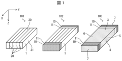
- FIG. 1 is a diagram showing a configuration of a graphite complex according to one embodiment of the present invention.
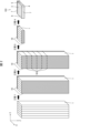
- FIG. 2 is a diagram showing steps of a method for producing a graphite composite according to one embodiment of the present invention.
- FIG. 2 is a diagram showing the configuration of a test sample and a test device used in an evaluation test of heat transfer performance in an embodiment of the present invention.
- a titanium-containing metal layer, an inorganic material layer, and the like are formed on the main surface of the anisotropic graphite.
- the inorganic material layer disposed on the main surface of the anisotropic graphite tends to inhibit the excellent heat diffusion ability of the anisotropic graphite.
- the anisotropic graphite has a property of being easily cracked along the crystal orientation plane of the graphite layer.
- the layer surrounding the anisotropic graphite can be made thinner and the structure of the layer surrounding the anisotropic graphite can be simplified, thereby improving the thermal diffusion capacity of the graphite composite.
- the unique geometry and composition of the adhesive layer reduces the degree of warping of the anisotropic graphite.
- the layer covering the periphery of the anisotropic graphite is, for example, a metal layer such as a first metal layer and a second metal layer.
- simplifying the configuration of the layer covering the periphery of the anisotropic graphite means, for example, that the configuration provided on the main surface of the anisotropic graphite is limited to only the first metal layer and the second metal layer.
- Fig. 1 is a diagram showing the configuration of a graphite composite according to one embodiment of the present invention.
- the graphite composite 103 is a graphite composite comprising anisotropic graphite 1 having a first main surface 30 parallel to the X-Y plane and a second main surface 31 opposite to the first main surface 30, in which the crystal orientation plane 20 of the graphite layer is arranged parallel to the X-Z plane when the X-axis, the Y-axis perpendicular to the X-axis, and the Z-axis perpendicular to the X-Y plane are taken as the X-axis, the first metal layer 3 provided on the first main surface 30 of the anisotropic graphite 1, the second metal layer 4 provided on the second main surface 31 of the anisotropic graphite 1, and an adhesive layer 11 and a reinforcing layer 10 provided on at least one of the surfaces of the anisotropic graphite 1 parallel to the Y-Z plane, the first metal layer 3 and the second metal layer 4 having thicknesses of 2 ⁇ m to 50 ⁇ m, and the adhesive layer 11
- a graphite composite according to one embodiment of the present invention includes anisotropic graphite 1.
- the anisotropic graphite 1 has a crystal orientation plane 20 of the graphite layer arranged parallel to the X-Z plane, and has a first main surface 30 parallel to the X-Y plane and a second main surface 31 opposite the first main surface 30.
- Anisotropic graphite 1 may have a block shape (e.g., a cube, a rectangular parallelepiped) in which a large number of layers (in other words, graphite layers) having a graphite structure in which hexagons are connected by covalent bonds are stacked. Note that anisotropic graphite 1 may be stacked so that the layers having the graphite structure are in direct contact with each other, or may be stacked via an adhesive member (e.g., adhesive, double-sided tape). Block-shaped anisotropic graphite has high thermal conductivity in directions parallel to the crystal orientation plane 20 of the graphite layer (e.g., the X-axis direction and the Z-axis direction).
- anisotropy of anisotropic graphite 1 means that the thermal conductivity of anisotropic graphite 1 is significantly different in each of the directions parallel to the crystal orientation plane 20 of the graphite layer (e.g., the X-axis direction and the Z-axis direction) and the direction perpendicular to the crystal orientation plane 20 of the graphite layer, since the graphite layer is oriented.
- Such anisotropic graphite 1 can be suitably produced using a known method, such as the method described in Patent Document 1 mentioned above.
- the thermal conductivity of anisotropic graphite 1 in the X-axis direction and Z-axis direction may be, for example, 1000 W/mK or more.
- the upper limit of the thermal conductivity of anisotropic graphite 1 in the X-axis direction and Z-axis direction is not particularly limited, but may be 2000 W/mK or less.
- the thermal conductivity of anisotropic graphite 1 in the Y-axis direction may be, for example, 0.3 W/mK or more and 20 W/mK or less.
- the first main surface 30 is a surface parallel to the X-Y plane
- the second main surface 31 is a surface opposite the first main surface 30 which is parallel to the X-Y plane (in other words, a surface parallel to the X-Y plane). Therefore, in anisotropic graphite 1, heat can be efficiently transported along the Z-axis direction (e.g., from the first main surface 30 to the second main surface 31) and/or along the X-axis direction.
- the thickness of the anisotropic graphite 1 is not limited, but is preferably 0.3 mm to 5.0 mm, more preferably 0.5 mm to 3.0 mm, and most preferably 0.7 mm to 2.0 mm. With this configuration, it is possible to realize a thin heat transfer element that can efficiently transport heat.
- the thickness of the anisotropic graphite 1 in the X-axis direction and the Y-axis direction is not limited and can be set appropriately according to the purpose of use.
- the thickness of the anisotropic graphite in the X-axis direction and the Y-axis direction can be, for example, 10 mm to 80 mm, or 10 mm to 50 mm.
- a graphite composite 103 according to one embodiment of the present invention comprises a first metal layer 3 provided on a first main surface 30 of anisotropic graphite 1, and a second metal layer 4 provided on a second main surface 31 of anisotropic graphite 1.
- anisotropic graphite 1 heat is efficiently transported along the Z-axis direction, so the first metal layer 3 and the second metal layer 4 can efficiently transfer the heat of anisotropic graphite 1 to other components.
- the anisotropic graphite 1 since at least a portion of the surface of the anisotropic graphite 1 is covered by the first metal layer 3 and the second metal layer 4, it is possible to prevent graphite powder from falling off the anisotropic graphite 1. If it is possible to prevent graphite powder from falling off the anisotropic graphite 1, it is possible to prevent a short circuit in an electronic circuit caused by graphite powder when, for example, a graphite composite according to one embodiment of the present invention is placed in an electronic device.
- first metal layer 3 and the second metal layer 4 make the anisotropic graphite 1 even less likely to crack.
- the first metal layer 3 and the second metal layer 4 may be provided so as to be in direct contact with the anisotropic graphite 1, or may be provided so as not to be in direct contact with the anisotropic graphite 1. It is preferable that the first metal layer 3 and the second metal layer 4 are provided so as to be in direct contact with the anisotropic graphite 1. With this configuration, heat can be directly transferred between the anisotropic graphite 1 and the first metal layer 3 and the second metal layer 4, so that a thin heat transfer element capable of efficient heat transport can be realized. Furthermore, with this configuration, the first metal layer 3 and the second metal layer 4 can more reliably cover at least a portion of the surface of the anisotropic graphite 1, and can more reliably make the anisotropic graphite 1 less likely to crack.
- the configuration of the first metal layer 3 and the second metal layer 4 is not particularly limited, but is preferably a metal vapor deposition layer, a metal layer formed by sputtering, a metal layer formed by thermal spraying, a plating layer, or a metal layer containing a metal-based brazing material, and is more preferably a plating layer.
- the plating layer may be a metal layer integrated with an inorganic material layer.
- the materials of the first metal layer 3 and the second metal layer 4 are not particularly limited, but preferably contain at least one selected from the group consisting of copper, nickel, and gold. Of these materials, copper is more preferable. With this configuration, it is possible to realize a heat transfer element that is both cost-effective and provides efficient heat transport.
- the thickness (thickness in the Z-axis direction) of the first metal layer 3 and the second metal layer 4 can be 2 ⁇ m to 50 ⁇ m, preferably 3 ⁇ m to 30 ⁇ m, and more preferably 5 ⁇ m to 10 ⁇ m. With this configuration, a heat transfer element that can transport heat more efficiently can be realized.
- a third metal layer 5 and a fourth metal layer 6 are preferably provided on both sides of the outermost layer of the anisotropic graphite 1 that is parallel to the X-Z plane.
- the third metal layer 5 and the fourth metal layer 6 make the anisotropic graphite 1 even less likely to crack.
- the third metal layer 5 and the fourth metal layer 6 may be provided so as to be in direct contact with the anisotropic graphite 1, or may be provided so as not to be in direct contact with the anisotropic graphite 1. It is preferable that the third metal layer 5 and the fourth metal layer 6 are provided so as to be in direct contact with the anisotropic graphite 1. With this configuration, the third metal layer 5 and the fourth metal layer 6 can more reliably cover at least a portion of the surface of the anisotropic graphite 1, and can more reliably make the anisotropic graphite 1 less likely to crack.
- the configuration of the third metal layer 5 and the fourth metal layer 6 may be similar to that of the first metal layer 3 and the second metal layer 4.
- the thickness (thickness in the Y-axis direction) of the third metal layer 5 and the fourth metal layer 6 is not particularly limited, but is preferably 2 ⁇ m to 50 ⁇ m, more preferably 3 ⁇ m to 30 ⁇ m, and most preferably 5 ⁇ m to 10 ⁇ m. This configuration not only prevents graphite powder from falling off the anisotropic graphite 1, but also allows for the realization of a thin heat transfer element.
- a graphite composite 103 includes a reinforcing layer 10 provided on at least one of the surfaces of the anisotropic graphite 1 that are parallel to the Y-Z plane.
- the reinforcing layer 10 is provided on both of the surfaces of the anisotropic graphite 1 that are parallel to the Y-Z plane.
- 102 in FIG. 1 shows a schematic configuration in which the first metal layer 3, the second metal layer 4, the third metal layer 5, and the fourth metal layer 6 are not provided.
- Anisotropic graphite has the property of being easily cracked along the X-Z plane (crystal orientation plane 20). For this reason, by providing a reinforcing layer 10 on at least one of the faces parallel to the Y-Z plane, the anisotropic graphite 1 can be made less likely to crack.
- the reinforcing layer may also be formed on the X-Z plane.
- the graphite composite according to one embodiment of the present invention may have a reinforcing layer provided on at least one of the faces of the anisotropic graphite that are parallel to the X-Z plane (or on both faces that are parallel to the X-Z plane).
- the configuration outside the X-Z plane of the anisotropic graphite can be the same as the configuration outside the Y-Z plane of the anisotropic graphite.
- the configuration includes a reinforcing layer 10, a reinforcing layer 10 and an adhesive layer 11, or a reinforcing layer 10, an adhesive layer 11, and a seventh metal layer.
- the thickness of the reinforcing layer 10 is not limited, but is preferably 50 ⁇ m to 500 ⁇ m, more preferably 100 ⁇ m to 400 ⁇ m, and most preferably 150 ⁇ m to 300 ⁇ m. This configuration not only makes it difficult for the anisotropic graphite 1 to crack, but also makes it possible to realize a thin heat transfer element.
- the thickness of the reinforcing layer 10 in the Y-axis direction and the Z-axis direction are not limited and can be set appropriately according to the size of the anisotropic graphite 1.
- the material of the reinforcing layer 10 is not particularly limited, but preferably includes at least one selected from the group consisting of resin, metal, and ceramic.
- the resin include acrylic resin, polypropylene, polyethylene, polyethylene terephthalate, polycarbonate, modified resin with various additives, and elastomer.
- the metal include gold, silver, copper, nickel, aluminum, molybdenum, tungsten, alloys containing these, and metal-based brazing materials.
- the ceramic include alumina, zirconia, silicon carbide, silicon nitride, boron nitride, and aluminum nitride. With this configuration, it is possible to obtain the advantage that the anisotropic graphite 1 can be made less likely to crack. From the viewpoint of obtaining this advantage better, polycarbonate and polyethylene terephthalate are more preferable among the resins, copper and aluminum are more preferable among the metals, and alumina and silicon carbide are more preferable among the ceramics.
- a graphite composite according to one embodiment of the present invention includes an adhesive layer 11 between anisotropic graphite 1 and reinforcing layer 10. This configuration allows anisotropic graphite 1 and reinforcing layer 10 to be bonded together via adhesive layer 11.
- the adhesive layer 11 contains a resin.
- the resin is not limited, and may be, for example, at least one selected from the group consisting of a thermosetting resin and a thermoplastic resin. More specifically, the resin may be at least one selected from the group consisting of an acrylic resin, a silicone resin, an epoxy resin, an ester resin, a phenolic resin, a polyimide resin, and a urethane resin. The resin may also be at least one selected from the group consisting of an acrylic resin, a silicone resin, and an epoxy resin.
- the adhesive layer 11 may contain components other than resin.
- the thickness of the adhesive layer 11 is not limited, but is preferably 5 ⁇ m to 500 ⁇ m, more preferably 8 ⁇ m to 100 ⁇ m, and most preferably 8 ⁇ m to 50 ⁇ m. This configuration not only allows the anisotropic graphite 1 and the reinforcing layer 10 to be firmly bonded together, but also allows a thin heat transfer element to be realized.
- the thickness of the adhesive layer 11 in the Y-axis direction and the Z-axis direction are not limited and can be set appropriately according to the size of the anisotropic graphite 1.
- the graphite composite 103 may have a fifth metal layer 7 on the outside of the reinforcing layer 10 (in other words, on the side of the reinforcing layer 10 opposite the adhesive layer 11).
- the fifth metal layer 7 covers at least a portion of the surface of the reinforcing layer 10 (in other words, at least a portion of the surface of the anisotropic graphite 1), which can better prevent graphite powder from falling off the anisotropic graphite 1.
- the fifth metal layer 7 makes the anisotropic graphite 1 even less likely to crack.
- the configuration of the fifth metal layer 7 is not particularly limited, but may be the same as the first metal layer 3 and the second metal layer 4.
- the thickness of the fifth metal layer 7 is not particularly limited, but is preferably 2 ⁇ m to 50 ⁇ m, more preferably 3 ⁇ m to 50 ⁇ m, and most preferably 5 ⁇ m to 10 ⁇ m. This configuration not only prevents graphite powder from falling off the anisotropic graphite 1, but also allows for a thin heat transfer element to be realized.
- the thickness of the fifth metal layer 7 in the Y-axis direction and the Z-axis direction is not limited and can be set appropriately according to the size of the anisotropic graphite 1.
- a manufacturing method of a graphite composite 103 is a manufacturing method of a graphite composite 103 comprising anisotropic graphite 1 having a first main surface 30 parallel to the X-Y plane and a second main surface 31 opposite the first main surface 30, in which the crystal orientation plane 20 of the graphite layer is arranged parallel to the X-Z plane when the X-axis, the Y-axis perpendicular to the X-axis, and the Z-axis perpendicular to the X-Y plane are taken as the X-axis, the Y-axis perpendicular to the X-Y plane, and the first main surface 30 parallel to the X-Y plane and the second main surface 31 opposite the first main surface 30, the manufacturing method of the graphite composite 10 includes a reinforcing step of forming a reinforcing layer 10 on at least one of the surfaces of the anisotropic graphite 1 parallel to the Y-Z plane, in which the anisotropic
- the reinforcing step is a step of forming a reinforcing layer 10 on at least one of the faces of the anisotropic graphite 1 that are parallel to the Y-Z plane (or on both faces of the anisotropic graphite 1 that are parallel to the Y-Z plane) (see step 1 in Figure 2).
- the specific configuration of the reinforcement process is not particularly limited, and for example, the anisotropic graphite 1 and the reinforcing layer 10 may be bonded together via the adhesive layer 11.
- a known method may be used as appropriate depending on the raw material of the adhesive layer 11.
- the adhesive layer 11 contains a resin.
- the resin is not limited, and may be, for example, at least one selected from the group consisting of a thermosetting resin and a thermoplastic resin. More specifically, the resin may be at least one selected from the group consisting of an acrylic resin, a silicone resin, an epoxy resin, an ester resin, a phenolic resin, a polyimide resin, and a urethane resin. The resin may also be at least one selected from the group consisting of an acrylic resin, a silicone resin, and an epoxy resin.
- the adhesive layer 11 may contain components other than resin.
- the manufacturing method of the graphite composite 103 preferably includes a cutting step of cutting the reinforcing layer 10 and the anisotropic graphite 1 (in other words, the composite of the reinforcing layer 10 and the anisotropic graphite 1) after the reinforcing step.
- the composite of the reinforcing layer 10 and the anisotropic graphite 1 can be cut along a cutting surface 50 parallel to the XY plane (see steps 2 and 3 in FIG. 2).
- a cutting surface 50 parallel to the XY plane see steps 2 and 3 in FIG. 2.
- the specific steps of the cutting process are not particularly limited, and examples include cutting with a wire saw, cutting with a mold, and cutting with a laser. Of these, cutting with a wire saw is preferred because of the advantage of productivity.
- the metal layer formation process is a process of forming a first metal layer 3 and a second metal layer 4 on the first main surface 30 and the second main surface 31, respectively, of the anisotropic graphite 1 on which the reinforcing layer 10 is formed (see process 4 in Figure 2).
- the metal layer formation process it is preferable to simultaneously form the first metal layer 3 and the second metal layer 4. This configuration allows for efficient production of a graphite composite.
- the first metal layer 3, the second metal layer 4, the third metal layer 5, and the fourth metal layer 6 may be formed simultaneously.
- the fifth metal layer 7 may also be formed simultaneously in the metal layer forming process.
- the fifth metal layer may be formed simultaneously with the first metal layer and the second metal layer without forming the third metal layer and/or the fourth metal layer. This configuration makes it possible to efficiently manufacture a graphite composite that can better prevent graphite powder from falling off the anisotropic graphite 1.
- the method for forming the first metal layer 3, the second metal layer 4, the third metal layer 5, the fourth metal layer 6, and the fifth metal layer 7 is not particularly limited, and any known method can be used as appropriate according to the raw materials of these metal layers. Examples of such methods include plating, attachment of a metal film with adhesive, metal vapor deposition, and sputtering. With this configuration, metal layers such as the first metal layer 3 and the second metal layer 4 can be formed directly on a configuration such as anisotropic graphite 1.
- anisotropic graphite 1 When forming a metal layer on anisotropic graphite 1 by plating or the like and then providing reinforcing layer 10 on said anisotropic graphite 1, it is necessary to place anisotropic graphite 1 in a plating tank while being held by a holding tool when plating.
- the metal layer include first metal layer 3, second metal layer 4, third metal layer 5, fourth metal layer 6, and fifth metal layer 7.
- the metal layer include first metal layer 3, second metal layer 4, third metal layer 5, fourth metal layer 6, and fifth metal layer 7.
- graphite powder is likely to fall off anisotropic graphite 1.
- anisotropic graphite 1 is likely to crack due to vibrations that occur when forming the metal layer.
- One embodiment of the present invention includes the inventions described in [1] to [50] below.
- Anisotropic graphite in which a crystal orientation plane of a graphite layer is arranged parallel to the X-Z plane, where the X-axis is an X axis, the Y-axis is perpendicular to the X-axis, and the Z-axis is perpendicular to the X-Y plane, and the graphite layer has a first main surface parallel to the X-Y plane and a second main surface opposite to the first main surface; a first metal layer disposed on a first major surface of the anisotropic graphite; a second metal layer disposed on a second major surface of the anisotropic graphite;
- the anisotropic graphite has an adhesive layer and a reinforcing layer provided on at least one of the surfaces parallel to the YZ plane, the first metal layer and the second metal layer have a thickness of 2 ⁇ m to 50 ⁇ m;
- the graphite composite wherein the adhesive layer comprises a resin.
- [4] A graphite composite according to any one of [1] to [3], in which the thickness of the reinforcing layer is 50 ⁇ m to 500 ⁇ m.
- the graphite composite described in any one of [1] to [19] further includes a fifth metal layer on the outside of the reinforcing layer.
- a method for producing a graphite composite comprising anisotropic graphite, the graphite layer having a crystal orientation plane arranged parallel to the X-Z plane, the graphite layer having a first main surface parallel to the X-Y plane, and a second main surface opposed to the first main surface, the method comprising the steps of: a reinforcing step of forming a reinforcing layer on at least one of the surfaces of the anisotropic graphite parallel to the YZ plane, the reinforcing layer being bonded to the anisotropic graphite via an adhesive layer; a metal layer forming step of forming a first metal layer and a second metal layer on a first main surface and a second main surface of the anisotropic graphite having the reinforcing layer formed thereon, the first metal layer and the second metal layer have a thickness of 2 ⁇ m to 50 ⁇ m;
- the method for producing a graphite composite wherein the adhesive layer contains a resin.
- [28] A method for producing a graphite composite according to any one of [24] to [27], comprising a cutting step of cutting the reinforcing layer and the anisotropic graphite after the reinforcing step.
- [38] A method for producing a graphite composite according to any one of [24] to [37], in which the thickness of the first metal layer and the second metal layer in the Z-axis direction is 2 ⁇ m to 50 ⁇ m.
- [41] A method for producing a graphite composite according to any one of [24] to [40], in which the thickness of the reinforcing layer in the X-axis direction is 50 ⁇ m to 500 ⁇ m.
- [46] A method for producing a graphite composite according to any one of [42] to [45], wherein the thickness of the third metal layer and the fourth metal layer in the Y-axis direction is 2 ⁇ m to 50 ⁇ m.
- Graphite Composite (A) Example 1 4,500 sheets of polyimide films, each measuring 100 mm x 100 mm x 25 ⁇ m thick, were laminated. Then, the laminate was heat-treated to 2,900° C. in an argon atmosphere while being pressed at a pressure of 40 kg/cm 2 to produce a graphite block (90 mm x 90 mm, thickness 45 mm). The thermal conductivity of the obtained graphite block in a direction parallel to the crystal orientation plane was 1,500 W/mK, and the thermal conductivity in a direction perpendicular to the crystal orientation plane was 5 W/mK.
- Example 4 A graphite composite (Q) was obtained in the same manner as in Example 1, except that, instead of the copper plating, a 50 ⁇ m-thick double-sided acrylic tape was used on the main surface as well, and an oxygen-free copper plate was attached at room temperature.
- thermal diffusivity of the test samples in the thickness direction was measured using a xenon flash analyzer LFA467 manufactured by Netzsch. Thermal diffusivity of 7 cm 2 /s or more was judged as “excellent”, thermal diffusivity of 4 cm 2 /s or more was judged as “good”, and thermal diffusivity of less than 4 cm 2 /s was judged as “poor”.
- the thermal diffusivity evaluation results are "poor” meaning not good, "good” meaning better than “poor”, and "excellent” meaning better than "good”, i.e., the best.
- Warpage evaluation> Using a VR-5000 manufactured by Keyence Corporation, the difference between the maximum height and the minimum height of the main surface of the test sample (maximum height - minimum height) was measured and determined as the warpage of the test sample. Warpage of less than 0.05 mm was judged as “excellent”, warpage of less than 0.1 mm as “good”, warpage of less than 0.15 mm as “passable”, and warpage of 0.15 mm or more as “failable”.
- the evaluation results for warpage are as follows: “failable” means not good, “passable” means better than “failable”, “good” means better than "passable”, and "excellent” means better than "good”, i.e., the best.
Landscapes
- Chemical & Material Sciences (AREA)
- Organic Chemistry (AREA)
- Life Sciences & Earth Sciences (AREA)
- General Life Sciences & Earth Sciences (AREA)
- Geology (AREA)
- Inorganic Chemistry (AREA)
- Cooling Or The Like Of Semiconductors Or Solid State Devices (AREA)
Abstract
熱拡散能力に優れ、異方性グラファイトが割れ難く、耐熱性に優れ、かつ、反りの度合いが小さいグラファイト複合体を実現するために、XYZ空間にて、グラファイト層の結晶配向面(20)がXZ平面に平行に配置し、XY平面に平行な第1主面(30)と第2主面(31)とを有する異方性グラファイト(1)と、特定の厚さの第1主面上の第1金属層(3)および第2主面上の第2金属層(4)と、YZ平面に平行な接着層(11)と補強層(10)と、を備える、グラファイト複合体(103)を用いる。
Description
本発明は、グラファイト複合体、およびグラファイト複合体の製造方法に関する。
電子機器および電子デバイスから発生する熱を移動させて放熱する素子として、グラファイトが広く利用されている。
とりわけ、炭素原子の六員環同士が共有結合で繋がってなるグラファイト構造を備え、かつ、グラファイト構造同士がファンデルワールス力で結合してなる異方性グラファイトは、高い熱伝導率を有する。そのため、異方性グラファイトは、電子機器および電子デバイスから発生する熱を効果的に移動させて放熱する素子として、注目されている。
例えば、特許文献1には、熱伝達素子として優れた熱伝達性能と長期信頼性とを備える異方性グラファイト、異方性グラファイト複合体、およびその製造方法が開示されている。特許文献1に記載の技術では、異方性グラファイトの主面の上に、チタン含有金属層、および無機材質層などが形成されている。
しかしながら、上述のような従来技術は優れたものではある。しかしながら、当該従来技術には、熱拡散能力を向上させることと、異方性グラファイトを割れ難くすることと、耐熱性を向上させることと、および反りの度合いを小さくすることと、を両立させるという面において、改善の余地があった。
本発明の一態様は、熱拡散能力に優れ、異方性グラファイトが割れ難く、耐熱性に優れ、かつ、反りの度合いが小さいグラファイト複合体を実現することを目的とする。
本発明の一実施形態に係るグラファイト複合体は、X軸、X軸に直交するY軸、X-Y平面に垂直なZ軸とした場合、グラファイト層の結晶配向面がX-Z平面に平行に配置してなり、X-Y平面に平行な第1主面と、当該第1主面に対向する第2主面と、を有する異方性グラファイトと、
前記異方性グラファイトの第1主面に設けられた第1金属層と、
前記異方性グラファイトの第2主面に設けられた第2金属層と、
前記異方性グラファイトにおける、Y-Z平面に平行な面の少なくとも一方の面に設けられた、接着層と補強層と、を備え、
前記第1金属層および前記第2金属層の厚さが2μm~50μmであり、
前記接着層は、樹脂を含む、グラファイト複合体である。
前記異方性グラファイトの第1主面に設けられた第1金属層と、
前記異方性グラファイトの第2主面に設けられた第2金属層と、
前記異方性グラファイトにおける、Y-Z平面に平行な面の少なくとも一方の面に設けられた、接着層と補強層と、を備え、
前記第1金属層および前記第2金属層の厚さが2μm~50μmであり、
前記接着層は、樹脂を含む、グラファイト複合体である。
本発明の一実施形態に係るグラファイト複合体の製造方法は、X軸、X軸に直交するY軸、X-Y平面に垂直なZ軸とした場合、グラファイト層の結晶配向面がX-Z平面に平行に配置してなり、X-Y平面に平行な第1主面と、当該第1主面に対向する第2主面と、を有する異方性グラファイトを備えるグラファイト複合体の製造方法であって、
前記異方性グラファイトのY-Z平面に平行な面の少なくとも一方の面に補強層を形成する補強工程であって、接着層を介して前記異方性グラファイトと前記補強層とを接着させる補強工程と、
前記補強層を形成した異方性グラファイトの第1主面および第2主面に、それぞれ第1金属層および第2金属層を形成する金属層形成工程と、を含み、
前記第1金属層および前記第2金属層の厚さが2μm~50μmであり、
前記接着層は、樹脂を含む、グラファイト複合体の製造方法である。
前記異方性グラファイトのY-Z平面に平行な面の少なくとも一方の面に補強層を形成する補強工程であって、接着層を介して前記異方性グラファイトと前記補強層とを接着させる補強工程と、
前記補強層を形成した異方性グラファイトの第1主面および第2主面に、それぞれ第1金属層および第2金属層を形成する金属層形成工程と、を含み、
前記第1金属層および前記第2金属層の厚さが2μm~50μmであり、
前記接着層は、樹脂を含む、グラファイト複合体の製造方法である。
本発明の一態様によれば、熱拡散能力に優れ、異方性グラファイトが割れ難く、耐熱性に優れ、かつ、反りの度合いが小さいグラファイト複合体を提供することができる。
本発明の一実施形態について以下に説明するが、本発明はこれに限定されるものではない。本発明は、以下に説明する各構成に限定されるものではなく、請求の範囲に示した範囲で種々の変更が可能である。また、異なる実施形態または実施例にそれぞれ開示された技術的手段を組み合わせて得られる実施形態または実施例についても、本発明の技術的範囲に含まれる。さらに、各実施形態にそれぞれ開示された技術的手段を組み合わせることにより、新しい技術的特徴を形成することができる。なお、本明細書中に記載された学術文献および特許文献の全てが、本明細書中において参考文献として援用される。また、本明細書において特記しない限り、数値範囲を表す「A~B」は、「A以上(Aを含みかつAより大きい)B以下(Bを含みかつBより小さい)」を意図する。
〔1.本発明の基本原理〕
上述したように、特許文献1に記載の技術では、異方性グラファイトの主面の上に、チタン含有金属層、および無機材質層などが形成されている。異方性グラファイトの主面の上に配置された無機材質層は、異方性グラファイトの優れた熱拡散能力を阻害する傾向を示す。更に、異方性グラファイトは、グラファイト層の結晶配向面に沿って割れやすいという性質を有する。
上述したように、特許文献1に記載の技術では、異方性グラファイトの主面の上に、チタン含有金属層、および無機材質層などが形成されている。異方性グラファイトの主面の上に配置された無機材質層は、異方性グラファイトの優れた熱拡散能力を阻害する傾向を示す。更に、異方性グラファイトは、グラファイト層の結晶配向面に沿って割れやすいという性質を有する。
本発明者は、以下の(i)~(iv)に示す事項を見出し、本発明を完成させるに至った。
(i)独自の配置を有する補強層によって、異方性グラファイトを割れ難くできること。
(ii)補強層を備えるが故に、異方性グラファイトの周囲を覆う層を薄くでき、かつ、異方性グラファイトの周囲を覆う層の構成を簡略化でき、これによって、グラファイト複合体の熱拡散能力を向上できること。
(iii)異方性グラファイトの周囲を覆う薄い層によって、異方性グラファイトをさらに割れ難くできること。
(iv)独自の配置および組成を有する接着層によって、異方性グラファイトの反りの度合いを小さくできること。
ここで、前記異方性グラファイトの周囲を覆う層は、例えば、第1金属層、および第2金属層などの金属層である。また、前記異方性グラファイトの周囲を覆う層の構成を簡略化することは、例えば、異方性グラファイトの主面に設ける構成を、第1金属層、および第2金属層のみとすることである。
ここで、前記異方性グラファイトの周囲を覆う層は、例えば、第1金属層、および第2金属層などの金属層である。また、前記異方性グラファイトの周囲を覆う層の構成を簡略化することは、例えば、異方性グラファイトの主面に設ける構成を、第1金属層、および第2金属層のみとすることである。
本発明の一態様によれば、熱拡散能力に優れ、異方性グラファイトが割れ難く、耐熱性に優れ、かつ、反りの度合いが小さいグラファイト複合体を提供することができる。本発明の一態様に係るこのような効果は、例えば、国際連合が提唱する持続可能な開発目標(SDGs)の目標12「持続可能な生産消費形態を確保する」等の達成にも貢献する可能性がある。
〔2.グラファイト複合体〕
図1を参照しながら、本発明の一実施形態に係るグラファイト複合体について説明する。なお、図1は、本発明の一実施形態に係るグラファイト複合体の構成を示す図である。
図1を参照しながら、本発明の一実施形態に係るグラファイト複合体について説明する。なお、図1は、本発明の一実施形態に係るグラファイト複合体の構成を示す図である。
本発明の一実施形態に係るグラファイト複合体103は、X軸、X軸に直交するY軸、X-Y平面に垂直なZ軸とした場合、グラファイト層の結晶配向面20がX-Z平面に平行に配置してなり、X-Y平面に平行な第1主面30と、第1主面30に対向する第2主面31と、を有する異方性グラファイト1と、異方性グラファイト1の第1主面30に設けられた第1金属層3と、異方性グラファイト1の第2主面31に設けられた第2金属層4と、異方性グラファイト1における、Y-Z平面に平行な面の少なくとも一方の面に設けられた、接着層11と補強層10と、を備え、第1金属層3および第2金属層4の厚さが2μm~50μmであり、接着層11は樹脂を含む、グラファイト複合体である。
図1の101に示すように、本発明の一実施形態に係るグラファイト複合体は、異方性グラファイト1を備えている。当該異方性グラファイト1は、図1の101に示すように、グラファイト層の結晶配向面20がX-Z平面に平行に配置してなり、X-Y平面に平行な第1主面30と、第1主面30に対向する第2主面31と、を有する。
異方性グラファイト1は、六員環が共有結合で繋がったグラファイト構造を有する層(換言すれば、グラファイト層)が多数積層した、ブロック状の形状(例えば、立方体、直方体)を有し得る。なお、異方性グラファイト1は、グラファイト構造を有する層が互いに直接接するように積層されたものであってもよいし、グラファイト構造を有する層が接着部材(例えば、接着剤、両面テープ)を介して積層されたものであってもよい。ブロック状の異方性グラファイトは、グラファイト層の結晶配向面20と平行な方向(例えば、X軸方向およびZ軸方向)に高い熱伝導性を有する。異方性グラファイト1の「異方性」とは、グラファイト層が配向していることから、グラファイト層の結晶配向面20と平行な方向(例えば、X軸方向およびZ軸方向)および垂直な方向(例えば、Y軸方向)のそれぞれにおいて、異方性グラファイト1の熱伝導性が大きく異なることを意味する。かかる異方性グラファイト1は、例えば、上述した特許文献1に記載の方法等の公知の手法を用いて好適に作製し得る。
異方性グラファイト1のX軸方向およびZ軸方向の熱伝導率は、例えば、1000W/mK以上であり得る。異方性グラファイト1のX軸方向およびZ軸方向の熱伝導率の上限は、特に限定されないが、2000W/mK以下であり得る。一方、異方性グラファイト1のY軸方向の熱伝導率は、例えば、0.3W/mK以上、20W/mK以下であり得る。
第1主面30は、X-Y平面に平行な面であり、第2主面31は、X-Y平面に平行な第1主面30に対向する面(換言すれば、X-Y平面に平行な面)である。それ故に、異方性グラファイト1では、Z軸方向に沿って(例えば、第1主面30から第2主面31に向かって)、および/または、X軸方向に沿って、効率よく熱輸送することができる。
異方性グラファイト1の厚さ(Z軸方向への厚さ)は、限定されないが、0.3mm~5.0mmであることが好ましく、0.5mm~3.0mmであることがより好ましく、0.7mm~2.0mmであることが最も好ましい。当該構成であれば、薄く、かつ、効率よく熱輸送することができる熱伝達素子を実現することができる。
異方性グラファイト1のX軸方向への厚さ、および、Y軸方向の厚さは、限定されず、利用目的に合わせて、適宜、設定することができる。異方性グラファイトのX軸方向への厚さ、および、Y軸方向の厚さは、例えば、10mm~80mm、または、10mm~50mmであり得る。
図1に示すように、本発明の一実施形態に係るグラファイト複合体103は、異方性グラファイト1の第1主面30上に設けられた第1金属層3と、異方性グラファイト1の第2主面31上に設けられた第2金属層4と、を備えている。
上述のとおり異方性グラファイト1では、Z軸方向に沿って、効率よく熱輸送されるため、第1金属層3および第2金属層4によって、異方性グラファイト1の熱を他の構成へ効率よく伝えることができる。
また、第1金属層3および第2金属層4によって異方性グラファイト1の表面の少なくとも一部を覆っているので、異方性グラファイト1からのグラファイト粉末の粉落ちを防ぐことができる。異方性グラファイト1からのグラファイト粉末の粉落ちを防ぐことができる場合、例えば、本発明の一実施形態に係るグラファイト複合体を電子機器内に配置したときに、グラファイト粉末によって生じる電子回路の短絡を防ぐことができる。
また、第1金属層3および第2金属層4によって、異方性グラファイト1をさらに割れ難くすることができる。
第1金属層3および第2金属層4は、異方性グラファイト1に直接接するように設けられていてもよいし、異方性グラファイト1に直接接しないように設けられていてもよい。第1金属層3および第2金属層4は、異方性グラファイト1に直接接するように設けられていることが好ましい。当該構成であれば、異方性グラファイト1と、第1金属層3および第2金属層4との間で、直接熱を受け渡しできるので、薄く、かつ、効率よく熱輸送することができる熱伝達素子を実現することができる。また、当該構成であれば、第1金属層3および第2金属層4によって、異方性グラファイト1の表面の少なくとも一部をより確実に覆うことができるとともに、異方性グラファイト1をより確実に割れ難くすることができる。
第1金属層3および第2金属層4の構成は、特に限定されないが、金属蒸着層、スパッタ処理による金属層、溶射による金属層、メッキ層、または金属系ろう材を含む金属層であることが好ましく、メッキ層であることがより好ましい。なお、メッキ層は、金属層と無機材質層とが一体になったものであってもよい。当該構成であれば、第1金属層3および第2金属層4を薄く構成することができるので、薄く、かつ、効率よく熱輸送することができる熱伝達素子を実現することができる。また、当該構成であれば、異方性グラファイト1の上に、他の構成を介することなく、第1金属層3および第2金属層4を形成することができる。
第1金属層3および第2金属層4の材料は、特に限定されないが、銅、ニッケル、および金からなる群より選択される少なくとも1種を含むことが好ましい。これらの材料の中では、銅がより好ましい。当該構成であれば、コストと、効率よい熱輸送とが両立した熱伝達素子を実現することができる。
第1金属層3および第2金属層4の厚さ(Z軸方向への厚さ)は、2μm~50μmであり得、3μm~30μmであることが好ましく、5μm~10μmであることがより好ましい。当該構成であれば、より効率よく熱輸送することができる熱伝達素子を実現することができる。
図1に示すように、本発明の一実施形態に係るグラファイト複合体103は、異方性グラファイト1における、X-Z平面に平行な面の最外層の両面に、それぞれ第3金属層5と第4金属層6とが設けられていることが好ましい。
第3金属層5および第4金属層6によって異方性グラファイト1の表面の少なくとも一部が覆われているので、異方性グラファイト1からのグラファイト粉末の粉落ちを防ぐことができる。
また、第3金属層5および第4金属層6によって、異方性グラファイト1をさらに割れ難くすることができる。
第3金属層5および第4金属層6は、異方性グラファイト1に直接接するように設けられていてもよいし、異方性グラファイト1に直接接しないように設けられていてもよい。第3金属層5および第4金属層6は、異方性グラファイト1に直接接するように設けられていることが好ましい。当該構成であれば、第3金属層5および第4金属層6によって、異方性グラファイト1の表面の少なくとも一部をより確実に覆うことができるとともに、異方性グラファイト1をより確実に割れ難くすることができる。
第3金属層5および第4金属層6の構成は、第1金属層3および第2金属層4と同様であり得る。
第3金属層5および第4金属層6の厚さ(Y軸方向への厚さ)は、特に限定されないが、2μm~50μmであることが好ましく、3μm~30μmであることがより好ましく、5μm~10μmであることが最も好ましい。当該構成であれば、異方性グラファイト1からのグラファイト粉末の粉落ちを防ぐことができるのみならず、薄い熱伝達素子を実現することができる。
図1に示すように、本発明の一実施形態に係るグラファイト複合体103は、異方性グラファイト1における、Y-Z平面に平行な面の少なくとも一方の面に設けられた補強層10を備えている。本発明の一実施形態に係るグラファイト複合体103では、補強層10は、異方性グラファイト1における、Y-Z平面に平行な面の両方の面に設けられていることが好ましい。図1の102は、第1金属層3、第2金属層4、第3金属層5および第4金属層6を設けていない構成を模式的に示す。
異方性グラファイトは、X-Z平面(結晶配向面20)に沿って割れやすいという性質を有する。このため、Y-Z平面に平行な面の少なくとも一方の面に補強層10を設けることにより、異方性グラファイト1を割れ難くすることができる。
なお、補強層は、X-Z面にも形成されていてもよい。つまり、本発明の一実施形態に係るグラファイト複合体は、異方性グラファイトにおける、X-Z平面に平行な面の少なくとも一方の面(または、X-Z平面に平行な面の両方の面)に設けられた補強層を備えていてもよい。
異方性グラファイトのX-Z平面よりも外側の構成は、異方性グラファイトのY-Z平面の外側の構成と同様の構成にすることができる。当該構成は、例えば、補強層10を含む構成、補強層10および接着層11を含む構成、または、補強層10、接着層11および第7金属層を含む構成である。
補強層10の厚さ(X軸方向への厚さ)は、限定されないが、50μm~500μmであることが好ましく、100μm~400μmであることがより好ましく、150μm~300μmであることが最も好ましい。当該構成であれば、異方性グラファイト1を割れ難くすることができるのみならず、薄い熱伝達素子を実現することができる。
補強層10のY軸方向への厚さ、および、Z軸方向の厚さは、限定されず、異方性グラファイト1のサイズに合わせて、適宜、設定することができる。
補強層10の材料は、特に限定されないが、樹脂、金属およびセラミックからなる群より選択される少なくとも1種を含むことが好ましい。前記樹脂としては、例えば、アクリル樹脂、ポリプロピレン、ポリエチレン、ポリエチレンテレフタラート、ポリカーボネート、各種添加物を加えた改質樹脂およびエラストマーを挙げることができる。前記金属としては、例えば、金、銀、銅、ニッケル、アルミニウム、モリブデン、タングステン、これらを含む合金、および金属系ろう材を挙げることができる。前記セラミックとしては、例えば、アルミナ、ジルコニア、炭化珪素、窒化珪素、窒化ホウ素、および窒化アルミを挙げることができる。当該構成であれば、異方性グラファイト1を割れ難くすることができるとの利点を得ることができる。当該利点をより良く得るという観点から、前記樹脂の中では、ポリカーボネートおよびポリエチレンテレフタラートが更に好ましく、前記金属の中では、銅およびアルミニウムが更に好ましく、前記セラミックの中では、アルミナおよび炭化珪素が更に好ましい。
図1に示すように、本発明の一実施形態に係るグラファイト複合体は、異方性グラファイト1と補強層10との間に、接着層11を備えている。当該構成によれば、接着層11を介して、異方性グラファイト1と補強層10とを接着させることができる。
接着層11は、樹脂を含むものである。当該樹脂は、限定されず、例えば、熱硬化性樹脂、および、熱可塑性樹脂からなる群から選択される少なくとも1つであり得る。より具体的に、当該樹脂は、アクリル樹脂、シリコン樹脂、エポキシ樹脂、エステル樹脂、フェノール樹脂、ポリイミド樹脂、および、ウレタン樹脂からなる群から選択される少なくとも1つであり得る。また、当該樹脂は、アクリル樹脂、シリコン樹脂、および、エポキシ樹脂からなる群から選択される少なくとも1つであってもよい。接着層11は、樹脂以外の成分を含むものであり得る。
接着層11の厚さ(X軸方向への厚さ)は、限定されないが、5μm~500μmであることが好ましく、8μm~100μmであることがより好ましく、8μm~50μmあることが最も好ましい。当該構成であれば、異方性グラファイト1と補強層10とを強固に接着させることができるのみならず、薄い熱伝達素子を実現することができる。
接着層11のY軸方向への厚さ、および、Z軸方向の厚さは、限定されず、異方性グラファイト1のサイズに合わせて、適宜、設定することができる。
本発明の一実施形態に係るグラファイト複合体103は、補強層10の外側(換言すれば、補強層10の、接着層11とは反対側)に、第5金属層7を備えていてもよい。
第5金属層7によって補強層10の表面の少なくとも一部(換言すれば、異方性グラファイト1の表面の少なくとも一部)を覆っているので、異方性グラファイト1からのグラファイト粉末の粉落ちを、より良く防ぐことができる。
また、第5金属層7によって、異方性グラファイト1をさらに割れ難くすることができる。
第5金属層7の構成は、特に限定されないが、第1金属層3および第2金属層4と同様であり得る。
第5金属層7の厚さ(X軸方向への厚さ)は、特に限定されないが、2μm~50μmであることが好ましく、3μm~50μmであることがより好ましく、5μm~10μmであることが最も好ましい。当該構成であれば、異方性グラファイト1からのグラファイト粉末の粉落ちを防ぐことができるのみならず、薄い熱伝達素子を実現することができる。
第5金属層7のY軸方向への厚さ、および、Z軸方向の厚さは、限定されず、異方性グラファイト1のサイズに合わせて、適宜、設定することができる。
〔2.グラファイト複合体の製造方法〕
図1および図2を参照しながら、本発明の一実施形態に係るグラファイト複合体103の製造方法について説明する。なお、上述した〔1.グラファイト複合体〕欄で既に説明した内容については、ここでは、その説明を省略する。
図1および図2を参照しながら、本発明の一実施形態に係るグラファイト複合体103の製造方法について説明する。なお、上述した〔1.グラファイト複合体〕欄で既に説明した内容については、ここでは、その説明を省略する。
本発明の一実施形態に係るグラファイト複合体103の製造方法は、X軸、X軸に直交するY軸、X-Y平面に垂直なZ軸とした場合、グラファイト層の結晶配向面20がX-Z平面に平行に配置してなり、X-Y平面に平行な第1主面30と、第1主面30に対向する第2主面31と、を有する異方性グラファイト1を備えるグラファイト複合体103の製造方法であって、異方性グラファイト1のY-Z平面に平行な面の少なくとも一方の面に補強層10を形成する補強工程であって、接着層11を介して異方性グラファイト1と補強層10とを接着させる補強工程と、補強層10を形成した異方性グラファイト1の第1主面30および第2主面31に、それぞれ第1金属層3および第2金属層4を形成する金属層形成工程と、を含み、第1金属層3および第2金属層4の厚さが2μm~50μmであり、接着層11は、樹脂を含む。
補強工程は、異方性グラファイト1のY-Z平面に平行な面の少なくとも一方の面(または、異方性グラファイト1のY-Z平面に平行な面の両方の面)に補強層10を形成する工程である(図2の工程1を参照)。
補強工程の具体的な構成は、特に限定されず、例えば、接着層11を介して、異方性グラファイト1と補強層10とを接着させてもよい。なお、接着層11を介して、異方性グラファイト1と補強層10とを接着させる方法としては、接着層11の原料に応じて、適宜、公知の方法を用いればよい。
接着層11は、樹脂を含むものである。当該樹脂は、限定されず、例えば、熱硬化性樹脂、および、熱可塑性樹脂からなる群から選択される少なくとも1つであり得る。より具体的に、当該樹脂は、アクリル樹脂、シリコン樹脂、エポキシ樹脂、エステル樹脂、フェノール樹脂、ポリイミド樹脂、および、ウレタン樹脂からなる群から選択される少なくとも1つであり得る。また、当該樹脂は、アクリル樹脂、シリコン樹脂、および、エポキシ樹脂からなる群から選択される少なくとも1つであってもよい。接着層11は、樹脂以外の成分を含むものであり得る。
本発明の一実施形態に係るグラファイト複合体103の製造方法は、前記補強工程の後に補強層10および異方性グラファイト1(換言すれば、補強層10および異方性グラファイト1の複合体)を切断する切断工程を含むことが好ましい。
切断工程では、例えば、補強層10および異方性グラファイト1の複合体を、X-Y平面に平行な切断面50に沿って切断することができる(図2の工程2~工程3を参照)。当該構成によれば、1つの大きなブロックから、グラファイト複合体103の前駆体を、複数得ることができる。更に、当該前駆体から、効率よく複数のグラファイト複合体103を製造することができる。
切断工程の具体的な工程は、特に限定されず、例えば、ワイヤーソーによる切断、金型による切断、およびレーザーによる切断を挙げることができる。生産性という利点が得られることから、これらの中では、ワイヤーソーによる切断が好ましい。
金属層形成工程は、補強層10が形成された異方性グラファイト1の第1主面30および第2主面31に、それぞれ第1金属層3および第2金属層4を形成する工程である(図2の工程4を参照)。
前記金属層形成工程では、第1金属層3と第2金属層4とを同時に形成することが好ましい。当該構成によれば、効率よくグラファイト複合体を製造することができる。
前記金属層形成工程において、第1金属層3と第2金属層4と第3金属層5と第4金属層6とを同時に形成してもよい。また、前記金属層形成工程において、第1金属層3~第4金属層6に加えて、さらに第5金属層7も同時に形成してもよい。さらに、前記金属層形成工程において、第1金属層と第2金属層と同時に、第3金属層および/または第4金属層を形成することなく、第5金属層を形成してもよい。当該構成によれば、異方性グラファイト1からのグラファイト粉末の粉落ちをより良く防ぐことができるグラファイト複合体を、効率よく製造することができる。
第1金属層3、第2金属層4、第3金属層5、第4金属層6、および第5金属層7を形成する方法は、特に限定されず、これらの金属層の原料に合わせて、適宜、公知の方法を用いることができる。当該方法としては、例えば、メッキ処理、接着剤のついた金属フィルムの貼り付け、金属蒸着、およびスパッタ処理を挙げることができる。当該構成によれば、異方性グラファイト1などの構成の上に、第1金属層3および第2金属層4などの金属層を、直接、形成することができる。
異方性グラファイト1に金属層をメッキ処理などによって形成した後で当該異方性グラファイト1に補強層10を設ける場合、異方性グラファイト1をメッキ処理する際に把持具により把持した状態でメッキ槽に入れる必要がある。ここで、当該金属層としては、例えば、第1金属層3、第2金属層4、第3金属層5、第4金属層6および第5金属層7を挙げることができる。その際、異方性グラファイト1の表面の把持具と接触している箇所に、金属層が形成されない箇所が生じやすい。この場合、異方性グラファイト1からのグラファイト粉末の粉落ちが生じやすくなるとの問題点が発生する。また、金属層を形成するときに生じる振動などによって、異方性グラファイト1が割れやすいとの問題点も発生する。
補強工程の後で金属層形成工程を行うことによって、上述した問題点を解決することができる。
本発明の一実施形態は、以下の〔1〕~〔50〕に記載の発明を包含する。
〔1〕X軸、X軸に直交するY軸、X-Y平面に垂直なZ軸とした場合、グラファイト層の結晶配向面がX-Z平面に平行に配置してなり、X-Y平面に平行な第1主面と、当該第1主面に対向する第2主面と、を有する異方性グラファイトと、
前記異方性グラファイトの第1主面に設けられた第1金属層と、
前記異方性グラファイトの第2主面に設けられた第2金属層と、
前記異方性グラファイトにおける、Y-Z平面に平行な面の少なくとも一方の面に設けられた、接着層と補強層と、を備え、
前記第1金属層および前記第2金属層の厚さが2μm~50μmであり、
前記接着層は、樹脂を含む、グラファイト複合体。
前記異方性グラファイトの第1主面に設けられた第1金属層と、
前記異方性グラファイトの第2主面に設けられた第2金属層と、
前記異方性グラファイトにおける、Y-Z平面に平行な面の少なくとも一方の面に設けられた、接着層と補強層と、を備え、
前記第1金属層および前記第2金属層の厚さが2μm~50μmであり、
前記接着層は、樹脂を含む、グラファイト複合体。
〔2〕前記異方性グラファイトのX軸方向への厚さおよびY軸方向の厚さは10mm~80mmである〔1〕に記載のグラファイト複合体。
〔3〕前記異方性グラファイトのZ軸方向への厚さは0.3mm~5.0mmである〔1〕または〔2〕に記載のグラファイト複合体。
〔4〕前記補強層の厚さが、50μm~500μmである、〔1〕~〔3〕の何れか1つに記載のグラファイト複合体。
〔5〕前記接着層に含まれる前記樹脂が、熱硬化性樹脂、および、熱可塑性樹脂からなる群から選択される少なくとも1つである、〔1〕~〔4〕の何れか1つに記載のグラファイト複合体。
〔6〕前記接着層に含まれる前記樹脂が、アクリル樹脂、シリコン樹脂、エポキシ樹脂、エステル樹脂、フェノール樹脂、ポリイミド樹脂、および、ウレタン樹脂からなる群から選択される少なくとも1つである、〔1〕~〔5〕の何れか1つに記載のグラファイト複合体。
〔7〕前記接着層に含まれる前記樹脂が、アクリル樹脂、シリコン樹脂、および、エポキシ樹脂からなる群から選択される少なくとも1つである、〔1〕~〔6〕の何れか1つに記載のグラファイト複合体。
〔8〕前記第1金属層および前記第2金属層が、前記異方性グラファイトに直接接している、〔1〕~〔7〕の何れか1つに記載のグラファイト複合体。
〔9〕前記第1金属層および前記第2金属層が、金属蒸着層、スパッタ処理による金属層、溶射による金属層、メッキ層、または金属系ろう材を含む金属層である、〔1〕~〔8〕の何れか1つに記載のグラファイト複合体。
〔10〕前記第1金属層および前記第2金属層が、銅、ニッケル、および金からなる群より選択される少なくとも1種を含む、〔1〕~〔9〕の何れか1つに記載のグラファイト複合体。
〔11〕前記第1金属層および前記第2金属層のZ軸方向への厚さが、2μm~50μmである、〔1〕~〔10〕の何れか1つに記載のグラファイト複合体。
〔12〕前記補強層は、樹脂、金属、およびセラミックからなる群より選択される少なくとも1種を含む、〔1〕~〔11〕の何れか1つに記載のグラファイト複合体。
〔13〕前記補強層は、前記異方性グラファイトにおける、Y-Z平面に平行な面の両方の面に設けられている、〔1〕~〔12〕の何れか1つに記載のグラファイト複合体。
〔14〕前記補強層のX軸方向への厚さは、50μm~500μmである、〔1〕~〔13〕の何れか1つに記載のグラファイト複合体。
〔15〕前記異方性グラファイトにおける、X-Z平面に平行な面の最外層の両面に、それぞれ第3金属層と第4金属層とが設けられている、〔1〕~〔14〕の何れか1つに記載のグラファイト複合体。
〔16〕前記第3金属層および前記第4金属層が、前記異方性グラファイトに直接接している、〔15〕に記載のグラファイト複合体。
〔17〕前記第3金属層および前記第4金属層が、金属蒸着層、スパッタ処理による金属層、溶射による金属層、メッキ層、または金属系ろう材を含む金属層である、〔15〕または〔16〕に記載のグラファイト複合体。
〔18〕前記第3金属層および前記第4金属層が、銅、ニッケル、および金からなる群より選択される少なくとも1種を含む、〔15〕~〔17〕の何れか1つに記載のグラファイト複合体。
〔19〕前記第3金属層および前記第4金属層のY軸方向への厚さが、2μm~50μmである、〔15〕~〔18〕の何れか1つに記載のグラファイト複合体。
〔20〕さらに、前記補強層の外側に第5金属層を含む、〔1〕~〔19〕の何れか1つに記載のグラファイト複合体。
〔21〕前記第5金属層が、金属蒸着層、スパッタ処理による金属層、溶射による金属層、メッキ層、または金属系ろう材を含む金属層である、〔20〕に記載のグラファイト複合体。
〔22〕前記第5金属層が、銅、ニッケル、および金からなる群より選択される少なくとも1種を含む、〔20〕または〔21〕に記載のグラファイト複合体。
〔23〕前記第5金属層のX軸方向への厚さが、2μm~50μmである、〔20〕~〔22〕の何れか1つに記載のグラファイト複合体。
〔24〕X軸、X軸に直交するY軸、X-Y平面に垂直なZ軸とした場合、グラファイト層の結晶配向面がX-Z平面に平行に配置してなり、X-Y平面に平行な第1主面と、当該第1主面に対向する第2主面と、を有する異方性グラファイトを備えるグラファイト複合体の製造方法であって、
前記異方性グラファイトのY-Z平面に平行な面の少なくとも一方の面に補強層を形成する補強工程であって、接着層を介して前記異方性グラファイトと前記補強層とを接着させる補強工程と、
前記補強層を形成した異方性グラファイトの第1主面および第2主面に、それぞれ第1金属層および第2金属層を形成する金属層形成工程と、を含み、
前記第1金属層および前記第2金属層の厚さが2μm~50μmであり、
前記接着層は、樹脂を含む、グラファイト複合体の製造方法。
前記異方性グラファイトのY-Z平面に平行な面の少なくとも一方の面に補強層を形成する補強工程であって、接着層を介して前記異方性グラファイトと前記補強層とを接着させる補強工程と、
前記補強層を形成した異方性グラファイトの第1主面および第2主面に、それぞれ第1金属層および第2金属層を形成する金属層形成工程と、を含み、
前記第1金属層および前記第2金属層の厚さが2μm~50μmであり、
前記接着層は、樹脂を含む、グラファイト複合体の製造方法。
〔25〕前記異方性グラファイトのX軸方向への厚さおよびY軸方向の厚さは10mm~80mmである〔24〕に記載のグラファイト複合体の製造方法。
〔26〕前記異方性グラファイトのZ軸方向への厚さは0.3mm~5.0mmである〔24〕または〔25〕に記載のグラファイト複合体の製造方法。
〔27〕前記補強層の厚さが、50μm~500μmである、〔24〕~〔26〕の何れか1つに記載のグラファイト複合体の製造方法。
〔28〕前記補強工程の後に前記補強層および前記異方性グラファイトを切断する切断工程を含む、〔24〕~〔27〕の何れか1つに記載のグラファイト複合体の製造方法。
〔29〕前記切断工程は、前記補強層および前記異方性グラファイトを、X-Y平面に平行な切断面に沿って切断する工程である、〔28〕の何れか1つに記載のグラファイト複合体の製造方法。
〔30〕前記切断工程は、ワイヤーソーによる切断、金型による切断およびレーザーによる切断からなる群から選択される方法によって、前記補強層および前記異方性グラファイトを切断する工程である、〔28〕または〔29〕の何れか1つに記載のグラファイト複合体の製造方法。
〔31〕前記接着層に含まれる前記樹脂が、熱硬化性樹脂、および、熱可塑性樹脂からなる群から選択される少なくとも1つである、〔24〕~〔30〕の何れか1つに記載のグラファイト複合体の製造方法。
〔32〕前記接着層に含まれる前記樹脂が、アクリル樹脂、シリコン樹脂、エポキシ樹脂、エステル樹脂、フェノール樹脂、ポリイミド樹脂、および、ウレタン樹脂からなる群から選択される少なくとも1つである、〔24〕~〔31〕の何れか1つに記載のグラファイト複合体の製造方法。
〔33〕前記接着層に含まれる前記樹脂が、アクリル樹脂、シリコン樹脂、および、エポキシ樹脂からなる群から選択される少なくとも1つである、〔24〕~〔32〕の何れか1つに記載のグラファイト複合体の製造方法。
〔34〕前記金属層形成工程では、前記第1金属層と前記第2金属層とを同時に形成する、〔24〕~〔33〕の何れか1つに記載のグラファイト複合体の製造方法。
〔35〕前記金属層形成工程では、前記第1金属層および前記第2金属層を、前記異方性グラファイトに直接接するように形成する、〔24〕~〔34〕の何れか1つに記載のグラファイト複合体の製造方法。
〔36〕前記第1金属層および前記第2金属層が、金属蒸着層、スパッタ処理による金属層、溶射による金属層、メッキ層、または金属系ろう材を含む金属層である、〔24〕~〔35〕の何れか1つに記載のグラファイト複合体の製造方法。
〔37〕前記第1金属層および前記第2金属層が、銅、ニッケル、および金からなる群より選択される少なくとも1種を含む、〔24〕~〔36〕の何れか1つに記載のグラファイト複合体の製造方法。
〔38〕前記第1金属層および前記第2金属層のZ軸方向への厚さが、2μm~50μmである、〔24〕~〔37〕の何れか1つに記載のグラファイト複合体の製造方法の製造方法。
〔39〕前記補強層は、樹脂、金属、およびセラミックからなる群より選択される少なくとも1種を含む、〔24〕~〔38〕の何れか1つに記載のグラファイト複合体の製造方法。
〔40〕前記補強工程では、前記補強層を、前記異方性グラファイトにおける、Y-Z平面に平行な面の両方の面に設ける、〔24〕~〔39〕の何れか1つに記載のグラファイト複合体の製造方法。
〔41〕前記補強層のX軸方向への厚さは、50μm~500μmである、〔24〕~〔40〕の何れか1つに記載のグラファイト複合体の製造方法。
〔42〕前記金属層形成工程において、さらに、前記異方性グラファイトにおけるX-Z平面に平行な面の最外層の両面に第3金属層および第4金属層を形成する、〔24〕~〔41〕の何れか1つに記載のグラファイト複合体の製造方法。
〔43〕前記金属層形成工程において、前記第3金属層および前記第4金属層を、前記異方性グラファイトに直接接するように形成する、〔42〕に記載のグラファイト複合体の製造方法。
〔44〕前記第3金属層および前記第4金属層が、金属蒸着層、スパッタ処理による金属層、溶射による金属層、メッキ層、または金属系ろう材を含む金属層である、〔42〕または〔43〕に記載のグラファイト複合体の製造方法。
〔45〕前記第3金属層および前記第4金属層が、銅、ニッケル、および金からなる群より選択される少なくとも1種を含む、〔42〕~〔44〕の何れか1つに記載のグラファイト複合体の製造方法。
〔46〕前記第3金属層および前記第4金属層のY軸方向への厚さが、2μm~50μmである、〔42〕~〔45〕の何れか1つに記載のグラファイト複合体の製造方法。
〔47〕前記金属層形成工程において、さらに、前記補強層の外側に第5金属層を形成する、〔42〕~〔46〕の何れか1つに記載のグラファイト複合体の製造方法。
〔48〕前記第5金属層が、金属蒸着層、スパッタ処理による金属層、溶射による金属層、メッキ層、または金属系ろう材を含む金属層である、〔47〕に記載のグラファイト複合体の製造方法。
〔49〕前記第5金属層が、銅、ニッケル、および金からなる群より選択される少なくとも1種を含む、〔47〕または〔48〕に記載のグラファイト複合体の製造方法。
〔50〕前記第5金属層のX軸方向への厚さが、2μm~50μmである、〔47〕~〔49〕の何れか1つに記載のグラファイト複合体の製造方法。
以下、実施例および比較例によって本発明の一実施形態をより詳細に説明するが、本発明はこれらに限定されるものではない。
<異方性グラファイト、およびグラファイト複合体の製造>
(グラファイト複合体(A):実施例1)
100mm×100mm×厚さ25μmのポリイミドフィルムを、4500枚積層した。その後、40kg/cm2の圧力でプレス加圧しながら、アルゴン雰囲気下、2900℃まで熱処理することにより、グラファイトブロック(90mm×90mm、厚さ45mm)を作製した。得られたグラファイトブロックの結晶配向面に平行な方向の熱伝導率は1500W/mKであり、結晶配向面に垂直な方向の熱伝導率は5W/mKであった。
(グラファイト複合体(A):実施例1)
100mm×100mm×厚さ25μmのポリイミドフィルムを、4500枚積層した。その後、40kg/cm2の圧力でプレス加圧しながら、アルゴン雰囲気下、2900℃まで熱処理することにより、グラファイトブロック(90mm×90mm、厚さ45mm)を作製した。得られたグラファイトブロックの結晶配向面に平行な方向の熱伝導率は1500W/mKであり、結晶配向面に垂直な方向の熱伝導率は5W/mKであった。
得られたグラファイトブロック(90mm×90mm、厚さ45mm)を、ワイヤーソーにて切断して異方性グラファイト1を得た。異方性グラファイト1の寸法は、異方性グラファイト1の結晶配向面をX-Z平面に平行に配置したときに、X軸に平行な辺の長さが39.6mm、Y軸に平行な辺の長さが29.99mm、Z軸に平行な辺の長さが80mmであった。
次に、異方性グラファイト1のY-Z平面に平行な面の両面に接着層11である29.99mm×80mm×50μmのアクリル両面テープを介して、補強層10である29.99mm×80mm×厚さ150μmの無酸素銅を接着させた。
当該方法により、X軸に平行な辺の長さが40mm、Y軸に平行な辺の長さが29.99mm、Z軸に平行な辺の長さが80mmである複合体を得た。
その後、複合体をワイヤーソーによってX-Y平面に平行に切断することによって、任意の厚みの複合体を得た。得られた複合体をメッキ処理して、表面に5μmの厚さの銅を析出させることによって、金属で被膜されたグラファイト複合体(A)を得た。当該被膜は、第1金属層3、第2金属層4に相当する。
図3の301の中央に、グラファイト複合体(A)の構成の概略を示すとともに、以下に、グラファイト複合体(A)の寸法を記載する:
・異方性グラファイト1のX-Y平面のサイズ:39.6mm×29.99mm、
・異方性グラファイト1のZ軸方向への厚さ:0.99mm、
・第1金属層3および第2金属層4のZ軸方向への厚さ:5μm、
・接着層11のX軸方向への厚さ:50μm、
・接着層11のZ軸方向への厚さ:0.99mm、
・接着層11の熱伝導率:0.2W/mK、
・補強層10のX軸方向への厚さ:150μm、
・補強層10のZ軸方向への厚さ:0.99mm。
・異方性グラファイト1のX-Y平面のサイズ:39.6mm×29.99mm、
・異方性グラファイト1のZ軸方向への厚さ:0.99mm、
・第1金属層3および第2金属層4のZ軸方向への厚さ:5μm、
・接着層11のX軸方向への厚さ:50μm、
・接着層11のZ軸方向への厚さ:0.99mm、
・接着層11の熱伝導率:0.2W/mK、
・補強層10のX軸方向への厚さ:150μm、
・補強層10のZ軸方向への厚さ:0.99mm。
(実施例2)
アクリル両面テープに代えて、シリコン両面テープを用いたこと以外は、実施例1と同様にして、グラファイト複合体(B)を得た。
アクリル両面テープに代えて、シリコン両面テープを用いたこと以外は、実施例1と同様にして、グラファイト複合体(B)を得た。
(実施例3)
アクリル両面テープに代えて、エポキシ樹脂テープを用い、銅板を180℃で接着したこと以外は、実施例1と同様にして、グラファイト複合体(C)を得た。
アクリル両面テープに代えて、エポキシ樹脂テープを用い、銅板を180℃で接着したこと以外は、実施例1と同様にして、グラファイト複合体(C)を得た。
(実施例4)
補強層に、無酸素銅板に代えて、アクリル板を用いたこと以外は、実施例1と同様にして、グラファイト複合体(D)を得た。
補強層に、無酸素銅板に代えて、アクリル板を用いたこと以外は、実施例1と同様にして、グラファイト複合体(D)を得た。
(実施例5)
補強層に、無酸素銅板に代えて、アクリル板を用いたこと以外は、実施例2と同様にして、グラファイト複合体(E)を得た。
補強層に、無酸素銅板に代えて、アクリル板を用いたこと以外は、実施例2と同様にして、グラファイト複合体(E)を得た。
(実施例6)
補強層に、無酸素銅板に代えて、アクリル板を用いたこと以外は、実施例3と同様にして、グラファイト複合体(F)を得た。
補強層に、無酸素銅板に代えて、アクリル板を用いたこと以外は、実施例3と同様にして、グラファイト複合体(F)を得た。
(実施例7)
以下の(i)に示すこと以外は、実施例1と同様にして、グラファイト複合体(G)を得た。
以下の(i)に示すこと以外は、実施例1と同様にして、グラファイト複合体(G)を得た。
(i)厚み36μmの株式会社カネカ製グラファイトシートと、厚み5μmのアクリル両面テープとを交互に積層し、グラファイトブロック(200mm×200mm、厚さ40mm)を作製したこと。
なお、得られたグラファイトブロックの結晶配向面に平行な方向の熱伝導率は1500W/mKであり、結晶配向面に垂直な方向の熱伝導率は3W/mKであった。
なお、得られたグラファイトブロックの結晶配向面に平行な方向の熱伝導率は1500W/mKであり、結晶配向面に垂直な方向の熱伝導率は3W/mKであった。
(実施例8)
アクリル両面テープに代えて、シリコン両面テープを用いたこと以外は、実施例7と同様にして、グラファイト複合体(H)を得た。
アクリル両面テープに代えて、シリコン両面テープを用いたこと以外は、実施例7と同様にして、グラファイト複合体(H)を得た。
(実施例9)
アクリル両面テープに代えて、エポキシ樹脂テープを用い、銅板を180℃で接着したこと以外は、実施例7と同様にして、グラファイト複合体(I)を得た。
アクリル両面テープに代えて、エポキシ樹脂テープを用い、銅板を180℃で接着したこと以外は、実施例7と同様にして、グラファイト複合体(I)を得た。
(実施例10)
以下の(ii)に示すこと以外は、実施例1と同様にして、グラファイト複合体(J)を得た。
以下の(ii)に示すこと以外は、実施例1と同様にして、グラファイト複合体(J)を得た。
(ii)厚み36μmの株式会社カネカ製グラファイトシートと、厚み5μmのポリエステル接着剤を交互に積層し、260℃-5MPa-5分熱プレスすることで、グラファイトブロック(200mm×200mm、厚さ40mm)を作製したこと。
なお、得られたグラファイトブロックの結晶配向面に平行な方向の熱伝導率は1500W/mKであり、結晶配向面に垂直な方向の熱伝導率は5W/mKであった。
なお、得られたグラファイトブロックの結晶配向面に平行な方向の熱伝導率は1500W/mKであり、結晶配向面に垂直な方向の熱伝導率は5W/mKであった。
(実施例11)
アクリル両面テープに代えて、シリコン両面テープを用いたこと以外は、実施例10と同様にして、グラファイト複合体(K)を得た。
アクリル両面テープに代えて、シリコン両面テープを用いたこと以外は、実施例10と同様にして、グラファイト複合体(K)を得た。
(実施例12)
アクリル両面テープに代えて、エポキシ樹脂テープを用い、銅板を180℃で接着したこと以外は、実施例10と同様にして、グラファイト複合体(L)を得た。
アクリル両面テープに代えて、エポキシ樹脂テープを用い、銅板を180℃で接着したこと以外は、実施例10と同様にして、グラファイト複合体(L)を得た。
(実施例13)
銅メッキ厚みを20μmにしたこと以外は、実施例1と同様にして、グラファイト複合体(M)を得た。
銅メッキ厚みを20μmにしたこと以外は、実施例1と同様にして、グラファイト複合体(M)を得た。
(比較例1)
以下の(iii)および(iv)に示すこと以外は、実施例1と同様にして、グラファイト複合体(N)を得た。
以下の(iii)および(iv)に示すこと以外は、実施例1と同様にして、グラファイト複合体(N)を得た。
(iii)アクリル両面テープに代えて、厚み10μmのチタン系活性銀ろうを用いたこと。
(iv)両面の補強層10の側から100kg/m2の加重を加えた状態で、異方性グラファイト1と接着層11と補強層10との複合体を、1×10-3Paの真空環境下、850℃にて30分間加熱して接着したこと。
(比較例2)
補強板として銅板を接着せず、側面上に直接、銅メッキを析出させたこと以外は、実施例1と同様にして、グラファイト複合体(O)を得た。
補強板として銅板を接着せず、側面上に直接、銅メッキを析出させたこと以外は、実施例1と同様にして、グラファイト複合体(O)を得た。
(比較例3)
以下の(v)に示すこと以外は、比較例1と同様にして、グラファイト複合体(P)を得た。
以下の(v)に示すこと以外は、比較例1と同様にして、グラファイト複合体(P)を得た。
(v)銅メッキに代えて、主面にも厚み10μmのチタン系活性銀ろうを用いて、無酸素銅板を100kg/m2の加重を加えた状態で、1×10-3Paの真空環境下、850℃にて30分間加熱して接着したこと。
(比較例4)
銅メッキに代えて、主面にも厚み50μmのアクリル両面テープを用い、室温で無酸素銅板を接着したこと以外は、実施例1と同様にして、グラファイト複合体(Q)を得た。
銅メッキに代えて、主面にも厚み50μmのアクリル両面テープを用い、室温で無酸素銅板を接着したこと以外は、実施例1と同様にして、グラファイト複合体(Q)を得た。
<強度の評価>
3点曲げ装置(IMADA社製)を用いて、50mm/minにて3点曲げ試験を行い、試験サンプルが破断する時点の応力を測定した。応力が20N以上のものを「優」、応力が12N以上のものを「良」、応力が8N以上のものを「可」、応力が8N未満のものを「不可」と判定した。ここで、強度の評価結果は、「不可」が良好ではないことを意味し、「可」が「不可」よりも良好であることを意味し、「良」が「可」よりも良好であることを意味し、「優」が「良」よりも良好、すなわち最も良好であることを意味する。
3点曲げ装置(IMADA社製)を用いて、50mm/minにて3点曲げ試験を行い、試験サンプルが破断する時点の応力を測定した。応力が20N以上のものを「優」、応力が12N以上のものを「良」、応力が8N以上のものを「可」、応力が8N未満のものを「不可」と判定した。ここで、強度の評価結果は、「不可」が良好ではないことを意味し、「可」が「不可」よりも良好であることを意味し、「良」が「可」よりも良好であることを意味し、「優」が「良」よりも良好、すなわち最も良好であることを意味する。
<耐熱性の評価>
試験サンプルをオーブンで30分加熱し、外形の変化がある温度を測定した。500℃でも変化のないものを「優」、300℃でも変化が無いものを「良」、200℃でも変化が無いものを「可」と判定した。ここで、耐熱性の評価結果は、「可」が良好であることを意味し、「良」が「可」よりも良好であることを意味し、「優」が「良」よりも良好、すなわち最も良好であることを意味する。
試験サンプルをオーブンで30分加熱し、外形の変化がある温度を測定した。500℃でも変化のないものを「優」、300℃でも変化が無いものを「良」、200℃でも変化が無いものを「可」と判定した。ここで、耐熱性の評価結果は、「可」が良好であることを意味し、「良」が「可」よりも良好であることを意味し、「優」が「良」よりも良好、すなわち最も良好であることを意味する。
<熱拡散率の評価>
ネッチ社製キセノンフラッシュアナライザーLFA467を用いて、試験サンプルの厚み方向の熱拡散率を測定した。熱拡散率7cm2/s以上のものを「優」、熱拡散率4cm2/s以上のものを「良」、熱拡散率4cm2/s未満のものを「不良」と判定した。ここで、熱拡散率の評価結果は、「不良」が良好ではないことを意味し、「良」が「不良」よりも良好であることを意味し、「優」が「良」よりも良好、すなわち最も良好であることを意味する。
ネッチ社製キセノンフラッシュアナライザーLFA467を用いて、試験サンプルの厚み方向の熱拡散率を測定した。熱拡散率7cm2/s以上のものを「優」、熱拡散率4cm2/s以上のものを「良」、熱拡散率4cm2/s未満のものを「不良」と判定した。ここで、熱拡散率の評価結果は、「不良」が良好ではないことを意味し、「良」が「不良」よりも良好であることを意味し、「優」が「良」よりも良好、すなわち最も良好であることを意味する。
<反りの評価>
キーエンス社製VR―5000を用いて、試験サンプルの主面の最大高さと最小高さとの差((最大高さ)-(最小高さ))を測定し、試験サンプルの反りとした。反りが0.05mm未満のものを「優」、反りが0.1mm未満のものを「良」、反りが0.15mm未満のものを「可」、反りが0.15mm以上のものを「不可」と判定した。ここで、反りの評価結果は、「不可」が良好ではないことを意味し、「可」が「不可」よりも良好であることを意味し、「良」が「可」よりも良好であることを意味し、「優」が「良」よりも良好、すなわち最も良好であることを意味する。
キーエンス社製VR―5000を用いて、試験サンプルの主面の最大高さと最小高さとの差((最大高さ)-(最小高さ))を測定し、試験サンプルの反りとした。反りが0.05mm未満のものを「優」、反りが0.1mm未満のものを「良」、反りが0.15mm未満のものを「可」、反りが0.15mm以上のものを「不可」と判定した。ここで、反りの評価結果は、「不可」が良好ではないことを意味し、「可」が「不可」よりも良好であることを意味し、「良」が「可」よりも良好であることを意味し、「優」が「良」よりも良好、すなわち最も良好であることを意味する。
〔試験結果〕
以下の表1に試験結果を示す。表1から明らかなように、本発明のグラファイト複合体は、「強度」、「耐熱性」、「熱拡散率」および「反り」の全ての評価が良好であった。すなわち、本発明のグラファイト複合体は、熱拡散能力に優れ、異方性グラファイトが割れ難く、耐熱性に優れ、かつ、反りの度合いが小さいことが示された。

以下の表1に試験結果を示す。表1から明らかなように、本発明のグラファイト複合体は、「強度」、「耐熱性」、「熱拡散率」および「反り」の全ての評価が良好であった。すなわち、本発明のグラファイト複合体は、熱拡散能力に優れ、異方性グラファイトが割れ難く、耐熱性に優れ、かつ、反りの度合いが小さいことが示された。
本発明は、熱伝達素子、より具体的に、電子機器および電子デバイスに用いる熱伝達素子に利用することができる。
1 異方性グラファイト
3 第1金属層
4 第2金属層
5 第3金属層
6 第4金属層
7 第5金属層
10 補強層
11 接着層
15 銅板
20 結晶配向面
30 第1主面
31 第2主面
50 切断面
100 熱源
103 グラファイト複合体
110 接着剤
120 試験サンプル
130 はんだ層
140 銅板
150 熱伝達係数
3 第1金属層
4 第2金属層
5 第3金属層
6 第4金属層
7 第5金属層
10 補強層
11 接着層
15 銅板
20 結晶配向面
30 第1主面
31 第2主面
50 切断面
100 熱源
103 グラファイト複合体
110 接着剤
120 試験サンプル
130 はんだ層
140 銅板
150 熱伝達係数
Claims (17)
- X軸、X軸に直交するY軸、X-Y平面に垂直なZ軸とした場合、グラファイト層の結晶配向面がX-Z平面に平行に配置してなり、X-Y平面に平行な第1主面と、当該第1主面に対向する第2主面と、を有する異方性グラファイトと、
前記異方性グラファイトの第1主面に設けられた第1金属層と、
前記異方性グラファイトの第2主面に設けられた第2金属層と、
前記異方性グラファイトにおける、Y-Z平面に平行な面の少なくとも一方の面に設けられた、接着層と補強層と、を備え、
前記第1金属層および前記第2金属層の厚さが2μm~50μmであり、
前記接着層は、樹脂を含む、グラファイト複合体。 - 前記異方性グラファイトのX軸方向への厚さおよびY軸方向の厚さは10mm~80mmであり、
Z軸方向への厚さは0.3mm~5.0mmである請求項1に記載のグラファイト複合体。 - 前記補強層の厚さが、50μm~500μmである、請求項1に記載のグラファイト複合体。
- 前記接着層に含まれる前記樹脂が、アクリル樹脂、シリコン樹脂、および、エポキシ樹脂からなる群から選択される少なくとも1つである、請求項1に記載のグラファイト複合体。
- 前記第1金属層および前記第2金属層が、前記異方性グラファイトに直接接している、請求項1に記載のグラファイト複合体。
- 前記第1金属層および前記第2金属層が、銅、ニッケル、および金からなる群より選択される少なくとも1種を含む、請求項1に記載のグラファイト複合体。
- 前記補強層は、樹脂、金属、およびセラミックからなる群より選択される少なくとも1種を含む、請求項1に記載のグラファイト複合体。
- 前記補強層は、前記異方性グラファイトにおける、Y-Z平面に平行な面の両方の面に設けられている、請求項1に記載のグラファイト複合体。
- 前記異方性グラファイトにおける、X-Z平面に平行な面の最外層の両面に、それぞれ第3金属層と第4金属層とが設けられている、請求項1に記載のグラファイト複合体。
- 前記第3金属層および前記第4金属層が、前記異方性グラファイトに直接接している、請求項9に記載のグラファイト複合体。
- さらに、前記補強層の外側に第5金属層を含む、請求項1に記載のグラファイト複合体。
- X軸、X軸に直交するY軸、X-Y平面に垂直なZ軸とした場合、グラファイト層の結晶配向面がX-Z平面に平行に配置してなり、X-Y平面に平行な第1主面と、当該第1主面に対向する第2主面と、を有する異方性グラファイトを備えるグラファイト複合体の製造方法であって、
前記異方性グラファイトのY-Z平面に平行な面の少なくとも一方の面に補強層を形成する補強工程であって、接着層を介して前記異方性グラファイトと前記補強層とを接着させる補強工程と、
前記補強層を形成した異方性グラファイトの第1主面および第2主面に、それぞれ第1金属層および第2金属層を形成する金属層形成工程と、を含み、
前記第1金属層および前記第2金属層の厚さが2μm~50μmであり、
前記接着層は、樹脂を含む、グラファイト複合体の製造方法。 - 前記補強工程の後に前記補強層および前記異方性グラファイトを切断する切断工程を含む、請求項12に記載のグラファイト複合体の製造方法。
- 前記接着層に含まれる前記樹脂が、アクリル樹脂、シリコン樹脂、および、エポキシ樹脂からなる群から選択される少なくとも1つである、請求項12に記載のグラファイト複合体の製造方法。
- 前記金属層形成工程では、前記第1金属層と前記第2金属層とを同時に形成する、請求項12に記載のグラファイト複合体の製造方法。
- 前記金属層形成工程において、さらに、前記異方性グラファイトにおけるX-Z平面に平行な面の最外層の両面に第3金属層および第4金属層を形成する、請求項12に記載のグラファイト複合体の製造方法。
- 前記金属層形成工程において、さらに、前記補強層の外側に第5金属層を形成する、請求項16に記載のグラファイト複合体の製造方法。
Applications Claiming Priority (2)
| Application Number | Priority Date | Filing Date | Title |
|---|---|---|---|
| JP2023219656 | 2023-12-26 | ||
| JP2023-219656 | 2023-12-26 |
Publications (1)
| Publication Number | Publication Date |
|---|---|
| WO2025142124A1 true WO2025142124A1 (ja) | 2025-07-03 |
Family
ID=96218878
Family Applications (1)
| Application Number | Title | Priority Date | Filing Date |
|---|---|---|---|
| PCT/JP2024/039240 Pending WO2025142124A1 (ja) | 2023-12-26 | 2024-11-05 | グラファイト複合体、およびグラファイト複合体の製造方法 |
Country Status (1)
| Country | Link |
|---|---|
| WO (1) | WO2025142124A1 (ja) |
Citations (5)
| Publication number | Priority date | Publication date | Assignee | Title |
|---|---|---|---|---|
| US5255738A (en) * | 1992-07-16 | 1993-10-26 | E-Systems, Inc. | Tapered thermal substrate for heat transfer applications and method for making same |
| JP2011023670A (ja) * | 2009-07-17 | 2011-02-03 | Thermo Graphitics Co Ltd | 異方性熱伝導素子及びその製造方法 |
| US20140284040A1 (en) * | 2013-03-22 | 2014-09-25 | International Business Machines Corporation | Heat spreading layer with high thermal conductivity |
| WO2016098890A1 (ja) * | 2014-12-18 | 2016-06-23 | 株式会社カネカ | グラファイト積層体、グラファイト積層体の製造方法、熱輸送用構造物およびロッド状の熱輸送体 |
| JP2021100006A (ja) * | 2018-03-28 | 2021-07-01 | 株式会社カネカ | 半導体パッケージ |
-
2024
- 2024-11-05 WO PCT/JP2024/039240 patent/WO2025142124A1/ja active Pending
Patent Citations (5)
| Publication number | Priority date | Publication date | Assignee | Title |
|---|---|---|---|---|
| US5255738A (en) * | 1992-07-16 | 1993-10-26 | E-Systems, Inc. | Tapered thermal substrate for heat transfer applications and method for making same |
| JP2011023670A (ja) * | 2009-07-17 | 2011-02-03 | Thermo Graphitics Co Ltd | 異方性熱伝導素子及びその製造方法 |
| US20140284040A1 (en) * | 2013-03-22 | 2014-09-25 | International Business Machines Corporation | Heat spreading layer with high thermal conductivity |
| WO2016098890A1 (ja) * | 2014-12-18 | 2016-06-23 | 株式会社カネカ | グラファイト積層体、グラファイト積層体の製造方法、熱輸送用構造物およびロッド状の熱輸送体 |
| JP2021100006A (ja) * | 2018-03-28 | 2021-07-01 | 株式会社カネカ | 半導体パッケージ |
Similar Documents
| Publication | Publication Date | Title |
|---|---|---|
| JP6096094B2 (ja) | 積層体、絶縁性冷却板、パワーモジュールおよび積層体の製造方法 | |
| JP3716832B2 (ja) | セラミック多層基板の製造方法および未焼成の複合積層体 | |
| TW201800365A (zh) | 陶瓷樹脂複合體 | |
| JPWO2017158993A1 (ja) | アルミニウム−ダイヤモンド系複合体及び放熱部品 | |
| WO2013015158A1 (ja) | 半導体素子用放熱部品 | |
| WO2008013279A1 (en) | Electronic component storing package and electronic device | |
| JP7440944B2 (ja) | 複合材料および放熱部品 | |
| US20170268834A1 (en) | Heat dissipation component for semiconductor element | |
| JP2021100006A (ja) | 半導体パッケージ | |
| JP2011023475A (ja) | 絶縁基板、絶縁回路基板、半導体装置、絶縁基板の製造方法及び絶縁回路基板の製造方法 | |
| CN114097075A (zh) | 陶瓷基板、电路基板及其制造方法、以及功率模块 | |
| WO2019188915A1 (ja) | 異方性グラファイト、異方性グラファイト複合体及びその製造方法 | |
| JP2018135251A (ja) | パワーモジュール用基板の製造方法 | |
| CN101341225A (zh) | 复合材料,特别是多层材料以及粘合剂或结合材料 | |
| JP2014107468A (ja) | アルミニウム−ダイヤモンド系複合体放熱部品 | |
| JP7142864B2 (ja) | 異方性グラファイト複合体の製造方法 | |
| JP2022003656A (ja) | 半導体パッケージ | |
| WO2025142124A1 (ja) | グラファイト複合体、およびグラファイト複合体の製造方法 | |
| JP2010109069A (ja) | 配線基板およびその製造方法 | |
| JP2020181926A (ja) | 高結晶性黒鉛の接合構造及び接合方法 | |
| WO2024111530A1 (ja) | グラファイト複合体、およびグラファイト複合体の製造方法 | |
| CN118851805A (zh) | 多层式复合陶瓷基板 | |
| WO2024004555A1 (ja) | グラファイト複合体、およびグラファイト複合体の製造方法 | |
| JP2000022055A (ja) | 炭素繊維複合放熱板 | |
| JP2020057649A (ja) | グラファイト複合体および半導体パッケージ |
Legal Events
| Date | Code | Title | Description |
|---|---|---|---|
| 121 | Ep: the epo has been informed by wipo that ep was designated in this application |
Ref document number: 24912017 Country of ref document: EP Kind code of ref document: A1 |