WO2025141871A1 - 交流直流変換装置、回転機駆動装置及び冷凍サイクル適用機器 - Google Patents
交流直流変換装置、回転機駆動装置及び冷凍サイクル適用機器 Download PDFInfo
- Publication number
- WO2025141871A1 WO2025141871A1 PCT/JP2023/047282 JP2023047282W WO2025141871A1 WO 2025141871 A1 WO2025141871 A1 WO 2025141871A1 JP 2023047282 W JP2023047282 W JP 2023047282W WO 2025141871 A1 WO2025141871 A1 WO 2025141871A1
- Authority
- WO
- WIPO (PCT)
- Prior art keywords
- capacitor
- power supply
- converter
- voltage
- control unit
- Prior art date
- Legal status (The legal status is an assumption and is not a legal conclusion. Google has not performed a legal analysis and makes no representation as to the accuracy of the status listed.)
- Pending
Links
Images




Classifications
-
- H—ELECTRICITY
- H02—GENERATION; CONVERSION OR DISTRIBUTION OF ELECTRIC POWER
- H02M—APPARATUS FOR CONVERSION BETWEEN AC AND AC, BETWEEN AC AND DC, OR BETWEEN DC AND DC, AND FOR USE WITH MAINS OR SIMILAR POWER SUPPLY SYSTEMS; CONVERSION OF DC OR AC INPUT POWER INTO SURGE OUTPUT POWER; CONTROL OR REGULATION THEREOF
- H02M7/00—Conversion of AC power input into DC power output; Conversion of DC power input into AC power output
- H02M7/02—Conversion of AC power input into DC power output without possibility of reversal
- H02M7/04—Conversion of AC power input into DC power output without possibility of reversal by static converters
- H02M7/12—Conversion of AC power input into DC power output without possibility of reversal by static converters using discharge tubes with control electrode or semiconductor devices with control electrode
Definitions
- This disclosure relates to an AC/DC converter that converts AC power into desired DC power, as well as a rotating machine drive device and a refrigeration cycle application device that are equipped with the AC/DC converter.
- a power factor correction circuit When obtaining DC voltage from an AC power source, it is common to use a power factor correction circuit.
- a power factor correction circuit has the functions of controlling the bus voltage at a constant level and controlling the power supply current so as to comply with harmonic standards.
- a power factor correction circuit and one of its control methods is a method in which switching is performed at least once per half cycle of the power supply voltage, which is the voltage of the AC power supply, and has the characteristic of being able to control the bus voltage to be lower than the peak value of the power supply voltage.
- the operating circuit switches from a boost chopper to a capacitor-input type diode rectifier, which creates the problem of distorting the power supply current.
- Patent Document 1 determines whether the combination of reactor capacity and switching timing complies with harmonic standards by repeating the design for each load power.
- Patent Document 1 the conventional technology described in Patent Document 1 is a method of checking whether or not it is possible to comply with harmonic standards by repeated trials, so there is a problem that the number of trials increases exponentially as the number of pulses increases. In addition, there is a problem that it takes a long time to complete the design for control gain design because there is no clear guideline for quantitative and unique design.
- PS Proportional Sinusoidal
- P Proportional
- the present disclosure has been made in consideration of the above, and aims to provide an AC/DC conversion device that is capable of performing stable current control while complying with harmonic standards without relying on trial-and-error adjustments.
- the AC-DC converter disclosed herein has the advantage of being able to comply with harmonic standards without relying on trial-and-error adjustments, while also being able to perform stable current control.
- FIG. 1 is a block diagram showing a configuration example of a rotary machine driving device according to a first embodiment; A circuit diagram showing a configuration example of an AC-DC converter according to a first embodiment.
- FIG. 2 is a diagram showing a configuration example of a control unit included in the AC-DC converter according to the first embodiment;
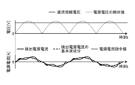
- FIG. 1 is a diagram showing examples of operational waveforms of a power supply voltage, a bus voltage, and a power supply current when a control unit of an AC-DC converter according to a first embodiment includes a PS controller.
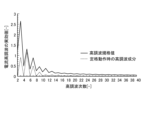
- FIG. 1 is a diagram showing an example of current harmonic characteristics when a control unit of an AC-DC converter according to a first embodiment includes a PS controller;
- FIG. 1 is a diagram showing an example of an operating waveform of an AC-DC converter according to a first embodiment
- FIG. 13 is a diagram showing an example of an operable range of control by a partial switching method when the inductance value of a reactor is 5 mH in the AC-DC converter according to the first embodiment
- FIG. 13 is a diagram showing an example of an operable range of control by a partial switching method when the inductance value of the reactor is set to 1 mH, 5 mH, and 10 mH in the AC-DC converter according to the first embodiment
- FIG. 1 is a diagram showing a configuration example of an AC-DC converter according to a second embodiment
- FIG. 13 is a diagram showing a configuration example of an AC-DC converter according to a third embodiment
- FIG. 13 is a diagram showing a configuration example of an AC-DC converter according to a fourth embodiment;
- FIG. 13 is a diagram showing a configuration example of an AC-DC converter according to a fifth embodiment;
- FIG. 13 is a diagram showing a configuration example of an AC-DC converter according to a sixth embodiment;
- FIG. 13 is a diagram showing a configuration example of an AC-DC converter according to a seventh embodiment;
- FIG. 13 is a diagram showing a configuration example of an AC-DC converter according to an eighth embodiment;
- FIG. 13 is a diagram showing a configuration example of an AC-DC converter according to a 9th embodiment;
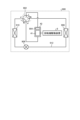
- FIG. 23 is a diagram showing a configuration example of a refrigeration cycle application device according to a tenth embodiment.
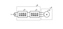
- Embodiment 1. 1 is a block diagram showing a configuration example of a rotating machine driving device 8 according to embodiment 1.
- the rotating machine driving device 8 is connected to an AC power source 1 and a load 4 including a motor 41.
- the rotating machine driving device 8 includes an AC/DC converter 2 and a DC/AC converter 3.
- the AC power source 1 is a single-phase AC power source that applies a power supply voltage to the AC/DC converter 2.
- the load 4 is a compressor or a fan
- the motor 41 is a compressor motor or a fan motor.
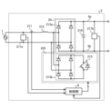
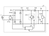
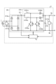
- FIG. 2 is a circuit diagram showing an example of the configuration of the AC-DC converter 2 according to the first embodiment.
- the AC-DC converter 2 according to the first embodiment mainly comprises a control unit 6, a rectifier circuit 20, a reactor 212, and a capacitor 216.
- the AC-DC converter 2 also comprises a current detector 211 and voltage detectors 217a and 217b as means for detecting voltage or current.
- the rectifier circuit 20 includes single-phase diode bridge cells 213a and 213b in which four diodes are bridge-connected, and a switching element 215 connected in parallel to both ends of the single-phase diode bridge cell 213b.
- the single-phase diode bridge cells 213a and 213b are connected in parallel to the AC power source 1.
- the rectifier circuit 20 as shown in FIG. 2 is called a "simple switching circuit.”
- the single-phase diode bridge cell 213b and the switching element 215 constitute a switching cell 225.
- the switching element 215 is disposed closer to the AC power source 1 than the capacitor 216.
- the switching element 215 performs a switching operation at least once per half cycle of the power source voltage. In this way, the rectifier circuit 20 has at least one switching element 215 and rectifies the power source voltage applied from the AC power source 1.
- the voltage detector 217b detects a bus voltage Vdc , which is the voltage of the DC buses 9a, 9b to which the capacitor 216 is connected.
- the voltage detector 217a detects the power supply voltage.
- the current detector 211 detects the power supply current flowing between the AC power supply 1 and the rectifier circuit 20.
- the control unit 6 receives the detection values of the voltage detection units 217a, 217b and the current detection unit 211. Based on each detection value, the control unit 6 generates a switching signal for controlling the on/off of the switching element 215.
- An example of the switching element 215 is an IGBT (Insulated Gate Bipolar Transistor) as shown in the figure, but is not limited to an IGBT. Any element capable of switching operation may be used as the switching element 215.
- Another example of the switching element 215 is a MOSFET (Metal-Oxide-Semiconductor Field-Effect Transistor).
- the AC-DC converter 2 shown in FIG. 2 is configured as a closed loop using the detection values of the voltage detectors 217a, 217b and the current detector 211, but may be configured as an open loop using target values, estimated values, etc. If the AC-DC converter 2 is configured as an open loop, it is also possible to control the switching element 215 without using the detection values of the voltage detectors 217a, 217b and the current detector 211.
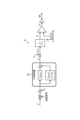
- Fig. 3 is a diagram showing an example of the configuration of the control unit 6 provided in the AC-DC conversion device 2 according to the first embodiment.
- the control unit 6 includes a PS controller 60 that is a current controller that performs current PS control.
- the transfer function G ACR(s) when current PS control is performed in a configuration using the PS controller 60 as shown in Fig. 3 can be expressed by the following equation (1).
- the S controller has a feature of improving the tracking performance for a sinusoidal input with an angular frequency ⁇ n .
- the reason why the tracking performance of the S controller improves for an input pulsating with an angular frequency ⁇ n can be explained from the internal model principle.
- the internal model principle states that if the controller's denominator has the same factors as the denominator polynomial of the command value expressed by the Laplace transform, the controller can follow the command value without deviation.
- the AC-DC converter 2 it is necessary to perform current feedback control in consideration of the power generated in the rectifier circuit 20 when in the diode rectifier mode. This is because the AC-DC converter 2 cannot control the power generated in the rectifier circuit 20 by the diode rectifier mode or less.
- the operating range of the AC-DC converter 2 is specified using a formula. In the following, for the sake of simplicity, the current feedback control will be simply referred to as feedback control.
Landscapes
- Engineering & Computer Science (AREA)
- Power Engineering (AREA)
- Rectifiers (AREA)
Priority Applications (2)
| Application Number | Priority Date | Filing Date | Title |
|---|---|---|---|
| PCT/JP2023/047282 WO2025141871A1 (ja) | 2023-12-28 | 2023-12-28 | 交流直流変換装置、回転機駆動装置及び冷凍サイクル適用機器 |
| JP2025566167A JPWO2025141871A1 (https=) | 2023-12-28 | 2023-12-28 |
Applications Claiming Priority (1)
| Application Number | Priority Date | Filing Date | Title |
|---|---|---|---|
| PCT/JP2023/047282 WO2025141871A1 (ja) | 2023-12-28 | 2023-12-28 | 交流直流変換装置、回転機駆動装置及び冷凍サイクル適用機器 |
Publications (1)
| Publication Number | Publication Date |
|---|---|
| WO2025141871A1 true WO2025141871A1 (ja) | 2025-07-03 |
Family
ID=96217188
Family Applications (1)
| Application Number | Title | Priority Date | Filing Date |
|---|---|---|---|
| PCT/JP2023/047282 Pending WO2025141871A1 (ja) | 2023-12-28 | 2023-12-28 | 交流直流変換装置、回転機駆動装置及び冷凍サイクル適用機器 |
Country Status (2)
| Country | Link |
|---|---|
| JP (1) | JPWO2025141871A1 (https=) |
| WO (1) | WO2025141871A1 (https=) |
Citations (2)
| Publication number | Priority date | Publication date | Assignee | Title |
|---|---|---|---|---|
| JPH11164562A (ja) * | 1997-09-24 | 1999-06-18 | Toshiba Corp | 電力変換装置及びこれを用いた空気調和機 |
| WO2021038880A1 (ja) * | 2019-08-30 | 2021-03-04 | 三菱電機株式会社 | 電力変換装置および空気調和機 |
-
2023
- 2023-12-28 JP JP2025566167A patent/JPWO2025141871A1/ja active Pending
- 2023-12-28 WO PCT/JP2023/047282 patent/WO2025141871A1/ja active Pending
Patent Citations (2)
| Publication number | Priority date | Publication date | Assignee | Title |
|---|---|---|---|---|
| JPH11164562A (ja) * | 1997-09-24 | 1999-06-18 | Toshiba Corp | 電力変換装置及びこれを用いた空気調和機 |
| WO2021038880A1 (ja) * | 2019-08-30 | 2021-03-04 | 三菱電機株式会社 | 電力変換装置および空気調和機 |
Also Published As
| Publication number | Publication date |
|---|---|
| JPWO2025141871A1 (https=) | 2025-07-03 |
Similar Documents
| Publication | Publication Date | Title |
|---|---|---|
| EP2309635B1 (en) | Ac-dc converter, ac-dc converter control method, motor driving device, compressor driving device, air conditioner, and heat pump-type hot-water supply device | |
| CN102138278A (zh) | 转换器电路、以及具备该转换器电路的电动机驱动控制装置、空气调节器、冰箱及感应加热烹饪器 | |
| US20170201186A1 (en) | Power conversion device and refrigeration cycle apparatus | |
| WO2012032910A1 (ja) | 電力変換装置、モータ駆動機器、冷凍空調機器 | |
| JP4493132B2 (ja) | 電源装置 | |
| JP7045529B2 (ja) | 電力変換装置および空気調和機 | |
| WO2022149211A1 (ja) | 電力変換装置、モータ駆動装置及び冷凍サイクル適用機器 | |
| WO2025141871A1 (ja) | 交流直流変換装置、回転機駆動装置及び冷凍サイクル適用機器 | |
| KR20140096627A (ko) | 전력변환장치 및 이를 포함하는 공기조화기 | |
| JP3966635B2 (ja) | 電源装置 | |
| WO2025141870A1 (ja) | 交流直流変換装置、回転機駆動装置及び冷凍サイクル適用機器 | |
| JP7625158B1 (ja) | 交流直流変換装置、回転機駆動装置及び冷凍サイクル適用機器 | |
| JP7603906B1 (ja) | 交流直流変換装置、回転機駆動装置及び冷凍サイクル適用機器 | |
| JP7603907B1 (ja) | 交流直流変換装置、回転機駆動装置及び冷凍サイクル適用機器 | |
| JP6505264B2 (ja) | 電力変換装置およびこれを用いた空気調和装置 | |
| WO2025141868A1 (ja) | 交流直流変換装置、回転機駆動装置及び冷凍サイクル適用機器 | |
| US20240396465A1 (en) | Power conversion device, motor drive device, and refrigeration-cycle application apparatus | |
| WO2025141872A1 (ja) | 交流直流変換装置、回転機駆動装置及び冷凍サイクル適用機器 | |
| WO2025141869A1 (ja) | 交流直流変換装置、回転機駆動装置及び冷凍サイクル適用機器 | |
| WO2025141866A1 (ja) | 交流直流変換装置、回転機駆動装置及び冷凍サイクル適用機器 | |
| WO2025141865A1 (ja) | 交流直流変換装置、回転機駆動装置及び冷凍サイクル適用機器 | |
| JP7774774B1 (ja) | 交流直流変換装置、回転機駆動装置、冷凍サイクル適用機器及び交流直流変換装置の制御方法 | |
| JP2004015944A (ja) | 電源装置 | |
| US20260063348A1 (en) | Method for controlling a compressor system, compressor for compressing a working medium, compressor system and refrigeration circuit system for carrying out a refrigeration cycle process | |
| WO2025141867A1 (ja) | 交流直流変換装置、回転機駆動装置及び冷凍サイクル適用機器 |
Legal Events
| Date | Code | Title | Description |
|---|---|---|---|
| 121 | Ep: the epo has been informed by wipo that ep was designated in this application |
Ref document number: 23963216 Country of ref document: EP Kind code of ref document: A1 |
|
| ENP | Entry into the national phase |
Ref document number: 2025566167 Country of ref document: JP Kind code of ref document: A |
|
| WWE | Wipo information: entry into national phase |
Ref document number: 2025566167 Country of ref document: JP |