WO2025134809A1 - 流体制御装置 - Google Patents
流体制御装置 Download PDFInfo
- Publication number
- WO2025134809A1 WO2025134809A1 PCT/JP2024/043182 JP2024043182W WO2025134809A1 WO 2025134809 A1 WO2025134809 A1 WO 2025134809A1 JP 2024043182 W JP2024043182 W JP 2024043182W WO 2025134809 A1 WO2025134809 A1 WO 2025134809A1
- Authority
- WO
- WIPO (PCT)
- Prior art keywords
- diaphragm
- piezoelectric body
- control device
- fluid control
- main surface
- Prior art date
- Legal status (The legal status is an assumption and is not a legal conclusion. Google has not performed a legal analysis and makes no representation as to the accuracy of the status listed.)
- Pending
Links
Images








Classifications
-
- F—MECHANICAL ENGINEERING; LIGHTING; HEATING; WEAPONS; BLASTING
- F04—POSITIVE - DISPLACEMENT MACHINES FOR LIQUIDS; PUMPS FOR LIQUIDS OR ELASTIC FLUIDS
- F04B—POSITIVE-DISPLACEMENT MACHINES FOR LIQUIDS; PUMPS
- F04B43/00—Machines, pumps, or pumping installations having flexible working members
- F04B43/02—Machines, pumps, or pumping installations having flexible working members having plate-like flexible members, e.g. diaphragms
- F04B43/04—Pumps having electric drive
Definitions
- the present invention relates to a fluid control device equipped with an actuator.
- the housing is placed on the outer side of the diaphragm, which increases the outer diameter of the actuator.
- the present invention aims to provide a fluid control device that prevents the sides of the piezoelectric body from coming into contact with obstacles when dropped or transported, and that can reduce the outer diameter.
- a fluid control device comprises an actuator and an annular frame that fixes at least a portion of the outer periphery of the actuator.
- the actuator comprises a piezoelectric body having a first main surface and a second main surface, and a vibration plate connected to the first main surface of the piezoelectric body.
- the frame is disposed on the second main surface.
- the outer diameter of the vibration plate and the outer diameter of the piezoelectric body are larger than the inner diameter of the frame, and the outer diameter of the vibration plate or the outer diameter of the frame is larger than the outer diameter of the piezoelectric body.
- the outer diameter of the vibration plate and the outer diameter of the piezoelectric body are larger than the inner diameter of the frame body, so a pump chamber can be formed on the side surface on the inner circumference of the frame body. Therefore, the fluid control device in this embodiment can form a pump chamber without placing a housing further outward from the piezoelectric body and vibration plate.
- the outer diameters of the members connected to the first main surface and the second main surface of the piezoelectric body are larger than the outer diameter of the piezoelectric body, obstacles and the like do not come into contact with the side surface of the piezoelectric element when it is dropped or transported.
- This invention prevents the sides of the piezoelectric body from coming into contact with obstacles when dropped or transported, and allows the outer diameter to be reduced.
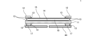
- FIG. 1 is a cross-sectional view of a fluid control device 1.
- FIG. FIG. FIG. FIG. 13 is a cross-sectional view of the fluid control device 1 when a flat plate 83 is attached to the lower surface of the frame 17.
- FIG. FIG. 1 is a cross-sectional view of a fluid control device 1A according to a first modified example.
- 2 is a bottom view of the piezoelectric body 10 in the fluid control device 1A.
- FIG. 4 is a cross-sectional view of the vibration plate 11 in the fluid control device 1A during bending vibration.
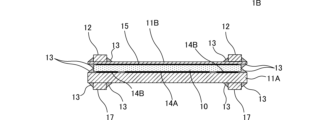
- FIG. FIG. 11 is a cross-sectional view of a fluid control device 1B according to a modified example 2.
- FIG. 4 is a cross-sectional view of a fluid control device 2 according to a second embodiment.
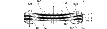
- FIG. 4 is a cross-sectional view of the fluid control device 2 during bending vibration.
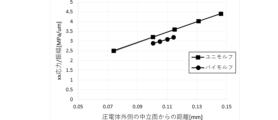
- FIG. 1 is a diagram showing the relationship between the distance from the neutral plane of a principal surface (the principal surface away from the neutral plane) of a piezoelectric body and stress/amplitude (stress per amplitude).
- FIG. 13 is a diagram showing the relationship between the distance from the neutral plane of the main surface of a piezoelectric body and the amplitude.
- FIG. 13 is a diagram showing the relationship between amplitude and radial stress at the center of a piezoelectric body.
- FIG. 13 is a cross-sectional view showing the structure of a bimorph modified example 1.
- FIG. 11 is a cross-sectional view showing the structure of a bimorph modified example 2.
- FIG. 1 is a diagram showing the relationship between the distance from the neutral plane of a principal surface (the principal surface away from the neutral plane) of a piezoelectric body and stress/amplitude (stress per amplitude).
- FIG. 11 is a cross-sectional view showing the structure of a modified example 3 of the bimorph.
- FIG. 13 is an exploded perspective view of a fluid control device 2D according to a fourth modified example.
- 1 is a cross-sectional view showing a portion of a fluid control device 2D below a first diaphragm 11A.
- FIG. 1 is a cross-sectional view showing a portion of a fluid control device 2D below a first diaphragm 11A.
- FIG. FIG. 2 is a plan view of the fluid control device 2D.
- FIG. 2 is a perspective view of a fluid control device 2D.
- FIG. 11 is a cross-sectional view showing the structure of another modified example of the fluid control device.
- FIG. 25 is a partially enlarged view of FIG. 24 .
- FIG. 1 is a cross-sectional view of a fluid control device 1 according to a first embodiment of the present invention.
- the fluid control device 1 includes a piezoelectric body 10, a vibration plate 11, a frame body 12, a fillet 13, a first electrode 14, a second electrode 15, and a frame body 17.
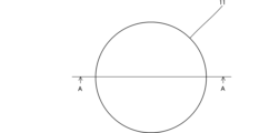
- FIG. 2 is a plan view of the diaphragm 11
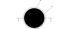
- FIG. 3 is a plan view of the piezoelectric body 10
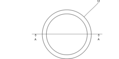
- FIG. 4 is a plan view of the frame body 12
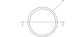
- FIG. 5 is a plan view of the frame body 17.
- the cross-sectional view of FIG. 1 is a cross-sectional view of line A-A shown in FIG. 2, FIG. 3, FIG. 4, and FIG. 5.
- the piezoelectric body 10 is made of, for example, lead zirconate titanate ceramics.
- the piezoelectric body 10 has a thin disk shape.
- a first electrode 14 is formed on the lower surface (first main surface) of the piezoelectric body 10 by, for example, sputtering, and a second electrode 15 is formed on the upper surface (second main surface) by, for example, sputtering.
- the piezoelectric body 10 is distorted by a driving voltage applied to the first electrode 14 and the second electrode 15.
- the outer diameter of the piezoelectric body 10 is larger than the outer diameters of the first electrode 14 and the second electrode 15 in a plan view.
- This configuration is not essential to the present invention, but this configuration prevents the electrodes (first electrode 14 and second electrode 15) from protruding from the side surface of the piezoelectric body 10. Therefore, when the electrodes are formed, they do not wrap around the side surface of the piezoelectric body 10, and short circuits can be suppressed.
- the diaphragm 11 is attached to the first electrode 14 with an adhesive.
- the adhesive contains a plurality of conductive fillers.
- the plurality of conductive fillers become conductive to each other when the thickness of the adhesive is equal to or less than a predetermined value.
- the adhesive becomes conductive when the thickness is equal to or less than the predetermined thickness, and becomes insulating when the thickness exceeds the predetermined thickness.
- the adhesive in the portion sandwiched between the diaphragm 11 and the first electrode 14 is equal to or less than the predetermined thickness and is conductive.
- the vibration plate 11 is disk-shaped.
- the outer diameter of the piezoelectric body 10 is smaller than the outer diameter of the vibration plate 11 in a plan view.
- a frame 17 is attached to the underside of the diaphragm 11 with an adhesive.
- the diaphragm 11 and frame 17 are made of a conductive material.
- a drive circuit (not shown) is connected to the frame 17. This allows a drive voltage to be applied to the diaphragm 11 via the frame 17.
- the frame 12 is attached to the second electrode 15 with an adhesive.
- the frame 12 is made of a conductive material.
- the adhesive in the portion sandwiched between the frame 12 and the second electrode 15 is less than a predetermined thickness and is conductive.
- a drive circuit (not shown) is connected to the frame 12. This allows a drive voltage to be applied via the frame 12.
- a drive voltage is applied to the first electrode 14 and the second electrode 15.
- the diaphragm 11 is designed to vibrate at a predetermined resonant frequency.
- a drive voltage with a frequency that matches the resonant frequency is applied to the first electrode 14 and the second electrode 15.
- the piezoelectric body 10 when a driving voltage is applied that causes the piezoelectric body 10 to contract in a direction parallel to the main surface, the upper surface of the vibration plate 11 contracts and the lower surface of the vibration plate 11 expands. Therefore, the lower surface of the vibration plate 11 is bent and deformed in a convex shape toward the lower surface. Also, if the piezoelectric body 10 expands in a direction parallel to the main surface, the lower surface of the vibration plate 11 is bent and deformed in a concave shape toward the upper surface. As a result, the vibration plate 11 vibrates in a rotationally symmetrical (concentric) shape from the center to the periphery. Therefore, the piezoelectric body 10 and the vibration plate 11 function as an actuator of a piezoelectric unimorph vibrator.
- the frame body 12 and the frame body 17 fix a part or the entire outer periphery of the actuator.
- the frame body 12 and the frame body 17 may be annular and arranged on the entire outer periphery of the actuator in a plan view, or may be arranged on only a part of the actuator in a plan view.
- the first main surface as an actuator is the lower surface of the vibration plate 11, and the second main surface corresponds to the upper surface of the piezoelectric body 10. If the vibration plate 11 is placed on the upper surface of the piezoelectric body 10, the first main surface of the actuator is the lower surface of the piezoelectric body 10, and the second main surface corresponds to the upper surface of the vibration plate 11.
- FIG. 6 is a cross-sectional view of the fluid control device 1 when a flat plate 83 is attached to the lower surface of the frame 17.
- the flat plate 83 is a plate-like member having a circular shape in plan view.
- the flat plate 83 has a through hole at the center in plan view.
- the flat plate 83 is arranged away from the vibration plate 11 by the frame 17.
- a pump chamber is formed in the space surrounded by the inner peripheral side of the frame 17, the lower surface of the vibration plate 11, and the upper surface of the flat plate 83.
- the vibration plate 11 vibrates, the flat plate 83 vibrates due to the pressure fluctuation in the pump chamber caused by the vibration of the vibration plate 11.
- the vibration phase of the flat plate 83 lags behind the vibration phase of the vibration plate 11. This effectively increases the thickness fluctuation of the gap space between the flat plate 83 and the vibration plate 11, further improving the pump's performance.
- the outer diameter of the vibration plate 11 and the outer diameter of the piezoelectric body 10 are larger than the inner diameter of the frame body 17, so that the inner peripheral side of the frame body 17 can form part of the housing of the fluid control device 1. Also, in the fluid control device 1, the outer diameter of the vibration plate 11 and the outer diameter of the piezoelectric body 10 are larger than the inner diameter of the frame body 12, so that the inner peripheral side of the frame body 12 can form part of the housing of the fluid control device 1. Therefore, the outer diameter of the entire device is smaller in the fluid control device 1 of this embodiment than in a structure in which the housing is disposed on the outer side of the vibration plate as in Patent Document 1 (JP Patent Publication 2009-293507).
- the outer diameters of the components (vibration plate 11 and frame 12) connected to the first and second main surfaces of the piezoelectric body 10 in the fluid control device 1 of this embodiment are larger than the outer diameter of the piezoelectric body 10. Therefore, the fluid control device 1 of this embodiment prevents obstacles from coming into contact with the sides of the piezoelectric body when it is dropped or transported.
- the fluid control device 1 of this embodiment can reduce the outer diameter without the side of the piezoelectric body coming into contact with obstacles when dropped or transported.
- fillets 13 are formed between the main surface of the piezoelectric body 10 and the main surface of the vibration plate 11, between the main surface of the piezoelectric body 10 and the side of the frame body 12, and between the main surface of the vibration plate 11 and the side of the frame body 17.
- the fillets 13 are formed by the overflow of the adhesive described above.
- the fillets 13 in each part are at least a predetermined thickness and therefore have insulating properties.
- the fillets 13 can prevent the peripheral parts of the frame body 12 and the vibration plate 11 from coming into contact and causing a short circuit.
- FIG. 7 is a cross-sectional view of a fluid control device 1A according to the first modified example.
- the same components as those in FIG. 1 are given the same reference numerals and will not be described.
- FIG. 8 is a bottom view of the piezoelectric body 10 in the fluid control device 1A.
- the electrode arranged on the lower surface is divided into an inner electrode 14A and an outer electrode 14B in a plan view.
- FIG. 9 is a cross-sectional view of the vibration plate 11 in the fluid control device 1A during bending vibration.
- the inner circumferential portion of the piezoelectric body 10 expands in a direction parallel to the main surface as shown in FIG. 9, the inner circumferential portion of the upper surface of the vibration plate 11 bends and deforms in a convex shape toward the upper surface.
- the outer circumferential portion of the upper surface of the vibration plate 11 tries to bend and deform in a convex shape toward the lower surface, opposite to the inner circumferential portion.
- the piezoelectric body 10 will apply a force in the outer circumferential portion in the opposite direction to the bending direction of the upper surface of the vibration plate 11. Also, although not shown, when the inner circumferential portion of the piezoelectric body 10 contracts in a direction parallel to the main surface, the inner circumferential portion of the upper surface of the vibration plate 11 bends and deforms in a concave shape toward the lower surface, and the outer circumferential portion of the upper surface of the vibration plate 11 tries to bend and deform in a convex shape toward the upper surface, opposite to the inner circumferential portion.
- the piezoelectric body 10 would exert a force on the outer periphery in the opposite direction to the bending direction of the top surface of the diaphragm 11.
- the polarization directions of the inner and outer circumferential portions of the piezoelectric body 10 are opposite. Therefore, when the inner circumferential portion of the piezoelectric body 10 expands in a direction parallel to the main surface, the outer circumferential portion of the piezoelectric body 10 contracts in a direction parallel to the main surface. Also, when the inner circumferential portion of the piezoelectric body 10 contracts in a direction parallel to the main surface, the outer circumferential portion of the piezoelectric body 10 expands in a direction parallel to the main surface.
- the bending direction of the diaphragm and the direction of the force applied to the diaphragm by the expansion and contraction of the piezoelectric body 10 are consistent between the inner and outer periphery.
- FIG. 10 is a cross-sectional view of a fluid control device 1B according to modification 2. Configurations common to those in FIG. 7 are given the same reference numerals and will not be described.
- a first vibration plate 11A is attached to the bottom surface (first main surface) of the piezoelectric body 10 with an adhesive
- a second vibration plate 11B is attached to the top surface (second main surface) of the piezoelectric body 10 with an adhesive
- a frame 12 is attached to the top surface of the second vibration plate 11B with an adhesive.
- the second vibration plate 11B is thinner than the first vibration plate 11A, making it more susceptible to deformation.
- the center of the second vibration plate 11B bends and deforms in a convex shape along the upper surface direction.
- a drive voltage is applied that contracts the inner peripheral portion of the piezoelectric body 10 in a direction parallel to the main surface
- the center of the second vibration plate 11B bends and deforms in a concave shape along the lower surface direction.
- the member that is joined to the frame body 12 is the second vibration plate 11B. Therefore, the mechanical stress that occurs at the joining position with the frame body 12 mainly affects the second vibration plate 11B, and the mechanical stress on the piezoelectric body 10 is reduced. In other words, in the fluid control device 1B, the mechanical stress on the piezoelectric body 10 due to deformation can be reduced, so cracks in the piezoelectric body 10 can be suppressed.
- FIG. 11 is a cross-sectional view of a fluid control device 2 according to a second embodiment.
- the same components as those of the fluid control device 1B shown in FIG. 10 are given the same reference numerals, and the description thereof will be omitted.
- the fluid control device 2 includes a first piezoelectric body 10A, a first vibration plate 11A, a second vibration plate 11B, a frame 12, a fillet 13, a first electrode 14, a second inner electrode 15A, a second outer electrode 15B, a second piezoelectric body 10B, a third vibration plate 11C, a third electrode 151, a fourth inner electrode 152A, a fourth outer electrode 152B, and a frame 17.
- the first piezoelectric body 10A has the same configuration and function as the piezoelectric body 10 of the first embodiment.
- the second piezoelectric body 10B has the same structure as the first piezoelectric body 10A.
- the second piezoelectric body 10B has a third principal surface and a fourth principal surface.
- a third electrode 151 is formed on the third principal surface of the second piezoelectric body 10B by, for example, sputtering, and a fourth inner electrode 152A and a fourth outer electrode 152B are formed on the fourth principal surface by, for example, sputtering.
- a second vibration plate 11B is attached to the fourth inner electrode 152A and the fourth outer electrode 152B by an adhesive.
- the second diaphragm 11B is attached to the third electrode 151 with an adhesive.
- the third diaphragm 11C is attached to the fourth inner electrode 152A and the fourth outer electrode 152B with an adhesive.
- Fillets 13 are formed between the main surface of the first vibration plate 11A and the side of the frame 17, between the main surface of the first piezoelectric body 10A and the main surface of the first vibration plate 11A, between the main surface of the first piezoelectric body 10A and the main surface of the second vibration plate 11B, between the main surface of the second piezoelectric body 10B and the main surface of the second vibration plate 11B, between the main surface of the second piezoelectric body 10B and the main surface of the third vibration plate 11C, and between the main surface of the third vibration plate 11C and the side of the frame 17.
- the outer diameters of the first piezoelectric body 10A and the second piezoelectric body 10B are smaller than the outer diameters of the first vibration plate 11A, the second vibration plate 11B, and the third vibration plate 11C in a plan view.
- the first diaphragm 11A, the second diaphragm 11B, and the third diaphragm 11C all have the same shape and the same outer diameter.
- the thickness of the first diaphragm 11A, the second diaphragm 11B, and the third diaphragm 11C are also the same.
- the second diaphragm 11B may be thinner or thicker than the first diaphragm 11A and the third diaphragm 11C.
- the outer diameter of the first vibration plate 11A, the outer diameter of the third vibration plate 11C, the outer diameter of the first piezoelectric body 10A, and the outer diameter of the second piezoelectric body 10B are larger than the inner diameters of the frame body 12 and the frame body 17. This allows the fluid control device 2 to form a pump chamber on the inner peripheral side of the frame body 12 or the frame body 17 and the lower surface of the first vibration plate 11A or the upper surface of the third vibration plate 11C.
- FIGS. 13, 14, and 15 are the stress that occurs in the radial direction (planar direction) from the main surface of the piezoelectric body at the center position when the piezoelectric body is viewed in a plane.
- the unimorph shown in FIGS. 13, 14, and 15 corresponds to the structure of the fluid control device 1B, and the bimorph corresponds to the structure of the fluid control device 2. In both cases, the thickness of the diaphragm is adjusted so that the resonant frequency of the actuator is constant.
- FIG. 22 is a plan view of the fluid control device 2D
- FIG. 23 is a perspective view of the fluid control device 2D.
- the cover member 85 is disposed on the bottom surface of the fluid control device 2D.
- the cover member 85 constitutes part of the housing of the fluid control device 2D.
- the cover member 85 prevents the components of the fluid control device 2D from coming into direct contact with external objects when the fluid control device 2D is dropped or transported. As a result, the cover member 85 can prevent damage to the fluid control device 2D.
- the cap 90 faces the third vibration plate 11C on the opposite side to the flat plate 83.
- the cap 90 is placed on the top surface of the fluid control device 2D.
- the cap 90 prevents the third vibration plate 11C from coming into direct contact with external objects when the fluid control device 2D is dropped or transported. This makes it possible for the cap 90 to prevent damage to the fluid control device 2D.
- the cap 90 has an opening 90B at its center. In plan view, the opening 90B overlaps with the center of the third diaphragm 11C. This prevents the top surface of the third diaphragm 11C from coming into contact with the cap 90 when the third diaphragm 11C is bent in a convex shape toward the top surface during operation. In other words, the cap 90 does not impede the vibration of the third diaphragm 11C, thereby preventing a decrease in performance as a pump.
- the first vibration plate 11A, the second vibration plate 11B, and the third vibration plate 11C each have a first outer peripheral terminal 110A, 111A, a second outer peripheral terminal 110B, 111B, and a third outer peripheral terminal 110C, 111C that protrude from the outer periphery.
- a drive circuit (not shown) is connected to the second outer terminal 111B and the frame 12.
- the frame 12 has a bent terminal 120
- the frame 17 has a bent terminal 170.
- the first diaphragm 11A and the third diaphragm 11C are electrically connected via the bent terminal 170 and the bent terminal 120, respectively. This allows a drive voltage to be applied to the first diaphragm 11A, the second diaphragm 11B, and the third diaphragm 11C.
- the first outer terminals 110A, 111A, the second outer terminals 110B, 111B, and the third outer terminals 110C, 111C do not overlap when viewed in a plan view. This prevents the first outer terminals 110A, 111A, the second outer terminals 110B, 111B, and the third outer terminals 110C, 111C from contacting each other, thereby preventing short circuits between the terminals.
- the outer diameter of the cover member 85 which is the housing of the fluid control device in a plan view, is located outside the outermost positions of the first outer terminals 110A, 111A, the second outer terminals 110B, 111B, and the third outer terminals 110C, 111C.
- the cover member 85 can suppress short circuits between the terminals due to contact with and deformation of the first outer terminals 110A, 111A, the second outer terminals 110B, 111B, and the third outer terminals 110C, 111C in the event of a drop impact, etc.
- the bent terminals 120 and 170 can shorten the path of the terminals leading to the outside, which can suppress noise caused by unnecessary vibrations and deterioration of pump performance caused by vibration leakage.
- the cap has a protruding portion 90A that protrudes outward in a plan view.
- the bent terminals 120 and 170 are pressed in the vertical direction by the protruding portion 90A.
- the vertical reaction force generated by the bent terminals 120 and 170 is pressed by the protruding portion 90A. This improves the strength of the joint.
- FIG. 24 is a cross-sectional view showing the structure of another modified example of a fluid control device.
- FIG. 25 is a partially enlarged view of FIG. 24.
- the fluid control device 1E according to the fourth modification example differs from the fluid control device 1A shown in FIG. 7 in that it includes a circuit board and in the shape of the electrode film formed on the piezoelectric body 10.
- the rest of the configuration of the fluid control device 1E is the same as that of the fluid control device 1A, and a description of similar parts will be omitted.
- the fluid control device 1E includes a piezoelectric body 10, a frame body 12, a fillet 13, a frame body 17, and a circuit board 18.
- the piezoelectric body 10 includes a main surface F101, a main surface F102, and a side surface F103.
- An inner electrode 14EA and an outer electrode 14EB are formed on the main surface F101.
- the outer electrode 14EB is shaped so that it does not reach the side surface F103.
- a second electrode 15E is formed on the main surface F102 and the side surface F103.
- the second electrode 15E is shaped to reach the corner where the side surface F103 and the main surface F101 intersect.
- the circuit board 18 is mainly composed of a laminate of insulator layers 181 and 182.
- An electrode pattern D181 is formed between the insulator layers 181 and 182.
- An electrode pattern D1821 and an electrode pattern D1822 are formed on the surface of the insulator layer 182 opposite the insulator layer 181 side.
- the electrode patterns D1821 and D1822 are spaced apart from each other.
- the electrode pattern D1822 is electrically connected to the electrode pattern D181 through a plurality of via electrodes VIA18 formed in the insulator layer 182.
- the piezoelectric body 10 is mounted on the circuit board 18.
- the inner electrode 14EA and the outer electrode 14EB of the piezoelectric body 10 are electrically connected to the electrode pattern D1822.
- the second electrode 15E of the piezoelectric body 10 is electrically connected to the electrode pattern D1821.
- an AC voltage is applied to the inner electrode 14EA and the outer electrode 14EB of the piezoelectric body 10 through the electrode pattern D1822 of the circuit board 18, the multiple via electrodes VIA18, and the electrode pattern D181.
- An AC voltage is applied to the second electrode 15E of the piezoelectric body 10 through the electrode pattern D1821.
- the circuit board 18 is a flat plate having a predetermined rigidity (elasticity). Therefore, the circuit board 18 functions as a vibration plate. This allows the fluid control device 1E to realize an actuator.
- the fillet 13 covers the electrode pattern D1821 of the circuit board 18 and the side surface F103 of the side surface F103 of the piezoelectric body 10. This makes it possible to prevent a short circuit between the electrode pattern D1821 and the frame body 12.
- the fluid control device 1E can achieve the same effects as the fluid control device 1A. Furthermore, the fluid control device 1E uses a circuit board that applies an AC voltage to the inner electrode 14EA, the outer electrode 14EB, and the second electrode 15E of the piezoelectric body 10 as a diaphragm. This allows the structure of the fluid control device 1E to be simplified, including the mechanism for applying the AC voltage.
- the inner peripheral surface of the frame is circular in plan view, but this is not limited to the above.
- the inner peripheral surface of the frame may be elliptical or regular polygonal in plan view.
- the inner diameter indicates the major axis, and in the case of a regular polygon, the inner diameter corresponds to the length of the diagonal.
- the outer shape of the piezoelectric body and the diaphragm is circular in plan view, but this is not limited to this.
- the outer diameter corresponds to the shortest distance from the center (the center of the shape of the inner circumferential surface of the frame when viewed in plan) when the frame is placed on the actuator composed of the piezoelectric body and the diaphragm.
- Fluid control device 10 Piezoelectric body 10A: First piezoelectric body 10B: Second piezoelectric body 11: Vibration plate 11A: First vibration plate 11B: Second vibration plate 11C: Third vibration plate 12: Frame 13: Fillet 14: First electrode 14A, 14EA: Inner electrode 14B, 14EB: Outer electrode 15: Second electrode 15A: Second inner electrode 15B: Second outer electrode 17: Frame 18: Circuit board 81: Joint member 82: Film valve 83: Flat plate 84: Flow path forming member 85: Cover member 90: Cap 90A: Protrusion 90B: Opening 110A, 111A: First outer peripheral terminal 110B, 111B: Second outer peripheral terminal 110C, 111C: Third outer peripheral terminal 120: Bent terminal 151: Third electrode 152A: Fourth inner peripheral electrode 152B: Fourth outer peripheral electrode 170: Bent terminals 181, 182: Insulator layers D1821, D1822: Electrode pattern VIA18: Vibration plate 11A: First vibration plate 11B: Second vibration plate 11C: Third vibration
Landscapes
- Engineering & Computer Science (AREA)
- Mechanical Engineering (AREA)
- General Engineering & Computer Science (AREA)
- Reciprocating Pumps (AREA)
Abstract
流体制御装置は、アクチュエータと、前記アクチュエータの外周の少なくとも一部を固定する環状の枠体と、を備える。前記アクチュエータは、第1主面と第2主面を有する圧電体と、前記圧電体の前記第1主面に接続される振動板と、を備える。前記枠体は、前記第2主面に配置される。前記振動板の外径および前記圧電体の外径が前記枠体の内径より大きく、前記振動板の外径または前記枠体の外径が前記圧電体の外径より大きい。
Description
本発明は、アクチュエータを備える流体制御装置に関する。
特許文献1には、板状の振動板に板状の圧電素子が貼り付けられたアクチュエータが開示されている。アクチュエータは、振動板の側面を覆うように筐体が配置されている。これにより、特許文献1のアクチュエータは、落下や搬送時に圧電素子の側面に障害物等が触れることがなくなる。
特許文献1の構造では、振動板の外側の側面に筐体が配置されるため、アクチュエータの外径が大きくなる。
本発明は、落下や搬送時に圧電体の側面に障害物等が触れることなく、かつ外径を小さくできる流体制御装置を提供することを目的とする。
本発明の一実施形態に係る流体制御装置は、アクチュエータと、前記アクチュエータの外周の少なくとも一部を固定する環状の枠体と、を備える。前記アクチュエータは、第1主面と第2主面を有する圧電体と、前記圧電体の前記第1主面に接続される振動板と、を備える。前記枠体は、前記第2主面に配置される。前記振動板の外径および前記圧電体の外径が前記枠体の内径より大きく、前記振動板の外径または前記枠体の外径が前記圧電体の外径より大きい。
上記構成によれば、振動板の外径および圧電体の外径は、枠体の内径より大きいため、枠体の内周側の側面においてポンプ室を構成できる。そのため、本実施形態における流体制御装置は、圧電体および振動板のさらに外周側に筐体を配置することなくポンプ室を構成できる。また、圧電体の第1主面および第2主面にそれぞれ接続されている部材の外径が圧電体の外径より大きいため、落下や搬送時に圧電素子の側面に障害物等が触れることがなくなる。
この発明によれば、落下や搬送時に圧電体の側面に障害物等が触れることなく、かつ外径を小さくできる。
本発明の第1の実施形態に係る流体制御装置について、図を参照して説明する。なお、以下の各実施形態に示す各図においては、説明を分かり易くするために、それぞれの構成要素の形状を部分的または全体として誇張して記載している。
図1は、本発明の第1の実施形態に係る流体制御装置1の断面図である。流体制御装置1は、圧電体10、振動板11、枠体12、フィレット13、第1電極14、第2電極15、および枠体17を備える。
図2は振動板11の平面図であり、図3は圧電体10の平面図であり、図4は枠体12の平面図であり、図5は枠体17の平面図である。図1の断面図は、図2、図3、図4および図5に示すA-A線の断面図である。
圧電体10は、例えばチタン酸ジルコン酸鉛系セラミックスから構成されている。圧電体10は、薄い円板形状である。圧電体10の下面(第1主面)には例えばスパッタリング等により第1電極14が形成され、上面(第2主面)には例えばスパッタリング等により第2電極15が形成されている。圧電体10は、第1電極14および第2電極15に印加される駆動電圧によって歪む。本実施形態では、平面視して、圧電体10の外径は、第1電極14および第2電極15の外径より大きい。当該構成は本発明において必須の構成ではないが、当該構成により圧電体10の側面に電極(第1電極14および第2電極15)がはみ出すことがない。したがって、電極の形成時に圧電体10の側面に電極が回り込むことがなく、短絡を抑制できる。
第1電極14には、接着剤により振動板11が貼り付けられている。接着剤は、複数の導電性フィラーを含む。当該複数の導電性フィラーは、接着剤の厚みが所定値以下となった場合に互いに導通する。したがって、接着剤は、所定の厚み以下で導電性となり、所定の厚みを超える場合に絶縁性となる。振動板11と第1電極14とに挟まれる部分の接着剤は、所定の厚み以下であり、導電性を有する。
振動板11は、円板形状である。本実施形態では、平面視して圧電体10の外径は、振動板11の外径よりも小さい。
振動板11の下面には接着剤により枠体17が貼り付けられている。振動板11および枠体17は、導電性材料からなる。枠体17には、不図示駆動回路が接続されている。これにより、振動板11には、枠体17を介して駆動電圧が印加される。
第2電極15には、接着剤により枠体12が貼り付けられている。枠体12は、導電性材料からなる。枠体12と第2電極15とに挟まれる部分の接着剤は、所定の厚み以下であり、導電性を有する。枠体12には、不図示駆動回路が接続されている。これにより、枠体12を介して駆動電圧が印加される。
したがって、駆動電圧は、第1電極14および第2電極15に印加される。振動板11は、所定の共振周波数で振動する様に設計されている。第1電極14および第2電極15には、当該共振周波数に合わせた周波数の駆動電圧が印加される。
例えば、圧電体10が主面に平行な方向に収縮する駆動電圧が印加されると、振動板11の上面が収縮し、振動板11の下面が伸張する。したがって、振動板11の下面が下面方向に向かって凸状に屈曲変形する。また、仮に圧電体10が主面に平行な方向に伸張すると、振動板11の下面が上面方向に向かって凹状に屈曲変形する。これにより、振動板11は中心部から周辺部にかけて回転対称形(同心円状)に屈曲振動する。したがって、圧電体10と振動板11は、圧電ユニモルフ振動子のアクチュエータとして機能する。枠体12および枠体17は、当該アクチュエータの外周の一部または全部を固定する。枠体12および枠体17は、平面視してアクチュエータの外周の全部に配置される環状であってもよいし、平面視して一部にのみ配置される態様であってもよい。図1に示す構造では、アクチュエータとしての第1主面は振動板11の下面であり、第2主面は圧電体10の上面に対応する。もし、振動板11が圧電体10の上面に配置されていれば、アクチュエータとしての第1主面は圧電体10の下面であり、第2主面は振動板11の上面に対応する。
振動板11の外径および圧電体10の外径は、枠体17の内径より大きい。また、振動板11の外径および圧電体10の外径は、枠体12の内径より大きい。これにより、流体制御装置1は、枠体12または枠体17の内周側の側面と、アクチュエータの上面または下面でポンプ室を形成することができる。図6は、枠体17の下面に平板83を取り付けた場合の流体制御装置1の断面図である。
平板83は平面視した形状が円形状の板状部材である。平板83は、平面視して中心位置に貫通孔を有する。平板83は、枠体17により振動板11から離間して配置されている。図6の構造では、枠体17の内周側の側面、振動板11の下面、および平板83の上面で囲まれる空間でポンプ室が形成される。振動板11が振動すると、平板83は、該振動板11の振動に伴うポンプ室内の圧力変動により振動する。平板83の振動位相は、振動板11の振動位相よりも遅れる。これにより、平板83と振動板11との間の隙間空間の厚さ変動が実質的に増加し、ポンプとしての能力はより向上する。
以上の様な本実施形態の流体制御装置1では、振動板11の外径および圧電体10の外径が枠体17の内径より大きいため、枠体17の内周側の側面で流体制御装置1の筐体の一部を構成することができる。また、流体制御装置1では、振動板11の外径および圧電体10の外径が枠体12の内径より大きいため、枠体12の内周側の側面で流体制御装置1の筐体の一部を構成することができる。したがって、本実施形態の流体制御装置1は、特許文献1(特開2009-293507号公報)のような振動板の外側の側面に筐体が配置される構造に比べて、装置全体の外径が小さくなる。
さらに、本実施形態の流体制御装置1における圧電体10の第1主面および第2主面にそれぞれ接続されている部材(振動板11および枠体12)の外径は、圧電体10の外径より大きい。したがって、本実施形態の流体制御装置1は、落下や搬送時に圧電体の側面に障害物等が触れることがなくなる。
すなわち、本実施形態の流体制御装置1は、落下や搬送時に圧電体の側面に障害物等が触れることなく、かつ外径を小さくできる。
さらに、本実施形態の流体制御装置1では、圧電体10の主面と振動板11の主面との間、圧電体10の主面と枠体12の側面との間、および振動板11の主面と枠体17の側面との間に、フィレット13が形成されている。フィレット13は、上述の接着剤のはみ出しにより形成されている。各部のフィレット13は、所定の厚み以上になるので、絶縁性を有する。フィレット13は、枠体12と振動板11の周辺部が接触して短絡することを防止することができる。
次に、図7は、変形例1に係る流体制御装置1Aの断面図である。図1と共通する構成については同一の符号を付し、説明を省略する。図8は、流体制御装置1Aにおける圧電体10の下面図である。
変形例1に係る流体制御装置1Aでは、下面(第1主面)に配置された電極が、平面視して、内周電極14Aと外周電極14Bに分割されている。
圧電体10のポーリング処理において、内周電極14Aおよび外周電極14Bは、第2電極15の電位を基準にして互いに逆極性の駆動電圧が印加される。したがって、圧電体10において、内周部と外周部の分極方向は逆になる。
図9は、流体制御装置1Aにおける振動板11の屈曲振動時の断面図である。図9の様に圧電体10の内周部分が主面に平行な方向に伸張すると、振動板11の上面の内周部分が上面方向に向かって凸状に屈曲変形する。一方、振動板11の外周の少なくとも一部分は枠体12および枠体17で固定されているため、振動板11の上面の外周部分は内周部分と逆に下面方向に向かって凸状に屈曲変形しようとする。このとき、仮に圧電体10の全てが主面に平行な方向に伸張すると、圧電体10は、外周部分では振動板11の上面の屈曲方向とは逆方向に力を与えることになる。また、図示はしないが、圧電体10の内周部分が主面に平行な方向に収縮すると、振動板11の上面の内周部分が下面方向に向かって凹状に屈曲変形し、振動板11の上面の外周部分は内周部分と逆に上面方向に向かって凸状に屈曲変形しようとする。このときも、仮に圧電体10の全てが主面に平行な方向に収縮すると、圧電体10は、外周部分では振動板11の上面の屈曲方向とは逆方向に力を与えることになる。
これに対して、本変形例1の流体制御装置1Aでは、圧電体10の内周部分と外周部分の分極方向は逆である。そのため、圧電体10の内周部分が主面に平行な方向に伸張すると、圧電体10の外周部分は主面に平行な方向に収縮する。また、圧電体10の内周部分が主面に平行な方向に収縮すると、圧電体10の外周部分は主面に平行な方向に伸張する。
したがって、本変形例1の流体制御装置1Aでは、振動板の屈曲方向と圧電体10の伸縮により振動板に与える力の方向が内周部分と外周部分とで一致する。これにより、本変形例1の流体制御装置1Aでは、同じ電圧あたりの振動板11の振幅を増加させることができる。
次に、図10は、変形例2に係る流体制御装置1Bの断面図である。図7と共通する構成については同一の符号を付し、説明を省略する。
流体制御装置1Bでは、圧電体10の下面(第1主面)には接着剤により第1振動板11Aが貼り付けられ、圧電体10の上面(第2主面)には接着剤により第2振動板11Bが貼り付けられている。第2振動板11Bの上面には接着剤により枠体12が貼り付けられている。第2振動板11Bは第1振動板11Aよりも薄いため、変形し易くなっている。
変形例2に係る流体制御装置1Bでは、圧電体10の内周部分が主面に平行な方向に伸張する駆動電圧が印加されると、第2振動板11Bの中心が上面方向に沿って凸状に屈曲変形する。圧電体10の内周部分が主面に平行な方向に収縮する駆動電圧が印加されると、第2振動板11Bの中心が下面方向に沿って凹状に屈曲変形する。
変形例2の流体制御装置1Bでは、枠体12と接合する部材が第2振動板11Bになる。したがって、枠体12との接合位置で生じる機械的ストレスは、主に第2振動板11Bに係り、圧電体10に係る機械的ストレスが少なくなる。つまり、流体制御装置1Bでは、変形による圧電体10への機械的ストレスを低下できるので圧電体10のクラックを抑制できる。
次に、図11は第2の実施形態に係る流体制御装置2の断面図である。図10に示した流体制御装置1Bと同様の構成については同じ符号を付し、説明を省略する。流体制御装置2は、第1圧電体10A、第1振動板11A、第2振動板11B、枠体12、フィレット13、第1電極14、第2内周電極15A、第2外周電極15B、第2圧電体10B、第3振動板11C、第3電極151、第4内周電極152A、第4外周電極152B、および枠体17を備える。
第1圧電体10Aは、第1実施形態の圧電体10と同じ構成および機能を有する。第2圧電体10Bは、第1圧電体10Aと同じ構造である。第2圧電体10Bは、第3主面および第4主面を有する。第2圧電体10Bの第3主面には例えばスパッタリング等により第3電極151が形成され、第4主面には例えばスパッタリング等により第4内周電極152Aおよび第4外周電極152Bが形成されている。第4内周電極152Aおよび第4外周電極152Bには、接着剤により第2振動板11Bが貼り付けられている。
第3電極151には、接着剤により第2振動板11Bが貼り付けられている。第4内周電極152Aおよび第4外周電極152Bには、接着剤により第3振動板11Cが貼り付けられている。
第1振動板11Aの主面と枠体17の側面との間、第1圧電体10Aの主面と第1振動板11Aの主面との間、第1圧電体10Aの主面と第2振動板11Bの主面との間、第2圧電体10Bの主面と第2振動板11Bの主面との間、第2圧電体10Bの主面と第3振動板11Cの主面との間、および第3振動板11Cの主面と枠体17の側面との間にはフィレット13が形成されている。
第3振動板11Cは、円板形状である。本実施形態において第1振動板11A、第2振動板11B、および第3振動板11Cの平面視した形状は同じであり、同じ外径である。
また、本実施形態では、平面視して第1圧電体10Aおよび第2圧電体10Bの外径は、第1振動板11A、第2振動板11B、および第3振動板11Cの外径よりも小さい。
本実施形態において、第1振動板11A、第2振動板11B、および第3振動板11Cは全て同じ形状であり、同じ外径である。第1振動板11Aの厚み、第2振動板11Bの厚み、および第3振動板11Cの厚みも同じである。ただし、第2振動板11Bは、第1振動板11Aおよび第3振動板11Cより薄くてもよいし、厚くてもよい。
第1振動板11A、第2振動板11B、および第3振動板11Cには、駆動電圧が印加される。第1振動板11A、第2振動板11B、および第3振動板11Cには、アクチュエータとしての共振周波数に合わせた周波数の駆動電圧が印加される。当該駆動電圧は、第1電極14、第2内周電極15A、第2外周電極15B、第3電極151、第4内周電極152A、および第4外周電極152Bに印加される。
第1圧電体10Aおよび第2圧電体10Bは、ポーリング処理における分極方向が逆になっている。また、第1圧電体10Aの内周部分と外周部分においてもポーリング処理における分極方向が逆になっている。第2圧電体10Bの内周部分と外周部分においてもポーリング処理における分極方向が逆になっている。
図12は、流体制御装置2の屈曲振動時の断面図である。図12の例では、第1圧電体10Aの内周部分が主面に平行な方向に収縮し、第1圧電体10Aの外周部分が主面に平行な方向に伸張する。また、第2圧電体10Bの内周部分が主面に平行な方向に伸張し、第1圧電体10Aの外周部分が主面に平行な方向に収縮する。
この場合、第3振動板11Cの内周部分が上面に凸状に屈曲変形し、第3振動板11Cの外周部分が下面に凹状に屈曲変形する。第1振動板11Aの内周部分は上面方向に凹状に屈曲変形し、第1振動板11Aの外周部分は下面方向に凸状に屈曲変形する。第2振動板11Bの上下方向の中心位置は主面に平行な方向の応力が略0の中立面となる。
第1振動板11Aの外径、第3振動板11Cの外径、第1圧電体10Aの外径、および第2圧電体10Bの外径は、枠体12および枠体17の内径より大きい。これにより、流体制御装置2は、枠体12または枠体17の内周側の側面と、第1振動板11Aの下面または第3振動板11Cの上面でポンプ室を形成することができる。
流体制御装置2に係る第1圧電体10Aおよび第2圧電体10Bのそれぞれの両主面には、振動板が配置されている。したがって、出力を上げるためにアクチュエータの振幅を大きくしても、圧電体が割れるおそれはない。特に、流体制御装置2は、平面視して、第1圧電体10Aおよび第2圧電体10Bの外径が、第1振動板11Aおよび第3振動板11Cの外径より小さい。そのため、落下や搬送時に特に第1圧電体10Aおよび第2圧電体10Bの側面が直接触れることがなくなるので、より破損を抑制できる。
さらに、本実施形態の流体制御装置2では、第1振動板11Aの主面と枠体17の側面との間、第1圧電体10Aの主面と第1振動板11Aの主面との間、第1圧電体10Aの主面と第2振動板11Bの主面との間、第2圧電体10Bの主面と第2振動板11Bの主面との間、第2圧電体10Bの主面と第3振動板11Cの主面との間、および第3振動板11Cの主面と枠体12の側面との間にフィレット13が形成されている。フィレット13は、上述の接着剤のはみ出しにより形成されている。したがって、第1振動板11A、第2振動板11B、および第3振動板11Cの周辺部が接触して短絡することを防止することができる。
流体制御装置2は、圧電バイモルフ振動子のアクチュエータを構成する。圧電バイモルフ振動子のアクチュエータは、圧電ユニモルフ振動子のアクチュエータを構成する流体制御装置1、1A,1Bに比べて、同じ駆動電圧でも効率よく曲げ振動に変換でき、電圧当たりの振幅を増加させることができる。
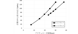
図13は、圧電体の主面(中立面から離れた側の主面)の中立面からの距離と、応力/振幅(振幅あたりの応力)との関係を示す図であり、図14は、圧電体主面の中立面からの距離と振幅との関係を示す図である。図15は、振幅と圧電体の中心における径方向応力との関係を示す図である。図13で示す応力は圧電体を平面視した時の中心の位置において、圧電体の主面から接線方向に生じる応力である。図15で示す応力は圧電体を平面視した時の中心の位置において、圧電体の主面から径方向(平面方向)に生じる応力である。図13、図14、および図15に示すユニモルフとは、流体制御装置1Bの構造であり、バイモルフとは流体制御装置2の構造に対応する。いずれもアクチュエータの共振周波数が一定となるよう、振動板の厚さが調整されている。
図13に示す様に、ユニモルフもバイモルフも、圧電体の主面の中立面からの距離が大きくなるほど振幅あたりの応力は大きくなる。また、圧電体の主面の中立面からの距離が同じ値では、圧電体に生じる応力はユニモルフのほうがわずかに大きい(バイモルフのほうが小さい)。一方で、図14に示す様に圧電体の主面の中立面からの距離が同じ値では、アクチュエータとしての振幅はバイモルフのほうがはるかに大きい。また、図15に示す様に圧電体の中心における径方向応力が同じ値では、アクチュエータとしての振幅はバイモルフのほうがはるかに大きい。
ユニモルフでは、圧電体の両方の主面に振動板が貼られて屈曲振動が阻害され、伸縮振動成分が増えるのに対して、バイモルフでは圧電体の両方の主面に振動板が貼られても、対となっている圧電体が互いに逆方向に伸縮して効率よく屈曲振動に変換される。従って、バイモルフでは、共振周波数調整のためにアクチュエータ最外層の振動板を厚くすることができるので、ユニモルフよりも中立面と圧電体の主面が近くなるため、圧電体に係る振幅あたりの応力が低下する。言い換えると、同じ応力であってもアクチュエータとしての振幅はバイモルフのほうがはるかに大きい。
したがって、流体制御装置2のようなバイモルフでは、流体制御装置1、1A,1Bの様なユニモルフよりも、出力を上げて振幅を大きくした場合に圧電体が壊れ難い。
次に、図16は、バイモルフの変形例1の構造を示す断面図である。図16の変形例1に係る流体制御装置2Aは、平面視した第1圧電体10Aおよび第2圧電体10Bの外径が、第2振動板11Bの外径よりも大きい。これにより、第1振動板11Aの端部と第2振動板11Bの端部との間に第1圧電体10Aが存在し、第3振動板11Cの端部と第2振動板11Bの端部と間に第2圧電体10Bが存在する。したがって、振動時に第1振動板11Aと第2振動板11Bとの接触、および、第3振動板11Cと第2振動板11Bの接触が発生する可能性をさらに低減し、短絡の可能性をより抑制できる。
次に、図17は、バイモルフの変形例2の構造を示す断面図である。図17の変形例2に係る流体制御装置2Bは、平面視した第1圧電体10A、第2圧電体10B、第1振動板11A、第2振動板11B、および第3振動板11Cの外径が全て同じである。
流体制御装置2Bにおいても、第1振動板11Aの主面と枠体17の側面との間、第1圧電体10Aの主面と第1振動板11Aの主面との間、第1圧電体10Aの主面と第2振動板11Bの主面との間、第2圧電体10Bの主面と第2振動板11Bの主面との間、第2圧電体10Bの主面と第3振動板11Cの主面との間、および第3振動板11Cの主面と枠体12の側面との間にフィレット13が形成されている。流体制御装置2Bにおいても、第1圧電体10Aおよび第2圧電体10Bのそれぞれの両主面には、振動板が配置されている。そのため、出力を上げるためにアクチュエータの振幅を大きくしても、圧電体が割れるおそれはない。
次に、図18は、バイモルフの変形例3の構造を示す分解斜視図である。変形例3に係る流体制御装置2Cは、平面視した形状が矩形状である。流体制御装置2Cは、平面視した形状が矩形状である以外は、図17に示した流体制御装置2Bと同じ構成、機能を備える。このように、本願発明の流体制御装置は、平面視した形状が矩形状であってもよい。
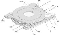
次に、図19は、変形例4に係る流体制御装置2Dの分解斜視図である。流体制御装置2Dは、さらに接合部材81、フィルム弁82、平板83、流路形成部材84、カバー部材85、およびキャップ90を備える。接合部材81、フィルム弁82、平板83、流路形成部材84、およびカバー部材85は、この順に第1振動板11Aの下に配置される。図20および図21は、流体制御装置2Dのうち第1振動板11A以下の部分を示す断面図である。なお、図20、図21では、カバー部材85の図示を省略している。
フィルム弁82は、可撓性を有する材料からなり、円板形状である。フィルム弁82は、平面視して第1振動板11Aの中心位置に配置されている。フィルム弁82は、円板状の接合部材81を介して第1振動板11Aの下面に接合されている。フィルム弁82の外径は接合部材81の外径より大きい。つまり、フィルム弁82の外端側の領域は接合されていない。これにより、フィルム弁82は、外端側の所定面積の領域が振動可能な状態で、第1振動板11Aに接合されている。なお、フィルム弁82は、円板形状に限らず、円環形状であってもよい。
平板83は板状部材である。平板83は、平面視して中心位置と外周付近に貫通孔を有する。平板83は、フィルム弁82から離間して配置されている。平板83は図6で説明した様に可撓性を有し、第1振動板11Aの振動に伴うポンプ室内の圧力変動により振動する。
流路形成部材84は板状部材である。流路形成部材84は、流路用の凹部は、平面視して円形の中央領域と、複数の線状領域とからなる。中央領域は、平面視して(平板83と流路形成部材84の積層方向に視て)平板83に形成された貫通孔と重なる。複数の線状領域の延びる方向の一方端は、中央領域に連通しており、他方端は、流路形成部材84におけるそれぞれに異なる外端付近に達している。これらの中央領域と、複数の線状領域と、平板83と、によりポンプ室中央部に連通する流路が形成される。
カバー部材85は、板状部材である。カバー部材85は、孔を有する。孔は、カバー部材85を厚み方向に貫通している。
第1振動板11Aの中央が平板83から離れると、図21に示すように、フィルム弁82の外縁側の領域(自由端側の領域)は、平板83側に湾曲し、平板83の表面に当接する。これにより、平板83の外周から中心につながる流路が塞がれ、ポンプ室外周から中央への流体の流入が抑制される。この様にしてフィルム弁82は、整流機構を構成する。
したがって、変形例4に係る流体制御装置2Dは、ポンプとしての性能を向上させることができる。
図22は、流体制御装置2Dの平面図であり、図23は、流体制御装置2Dの斜視図である。
カバー部材85は、流体制御装置2Dの最下面に配置される。カバー部材85は、流体制御装置2Dの筐体の一部を構成する。カバー部材85により、流体制御装置2Dの落下や搬送時に流体制御装置2Dの各部材に外部の物を直接触れさせることがなくなる。これにより、カバー部材85は、流体制御装置2Dの破損を抑制できる。
キャップ90は、平板83と反対側で第3振動板11Cに対向する。キャップ90は、流体制御装置2Dの最上面に配置される。キャップ90により、流体制御装置2Dの落下や搬送時に第3振動板11Cが外部の物に直接触れることがなくなる。これにより、キャップ90は、流体制御装置2Dの破損を抑制できる。
キャップ90は、中心位置に開口90Bを有する。開口90Bは、平面視して第3振動板11Cの中心位置に重なる。これにより、駆動時に第3振動板11Cが上面に向かって凸状に屈曲した時、第3振動板11Cの上面がキャップ90に接触することを抑制することができる。つまり、キャップ90が第3振動板11Cの振動を阻害しないため、ポンプとしての性能の低下を抑制できる。
第1振動板11A、第2振動板11B、および第3振動板11Cは、それぞれ外周側にそれぞれ突出する第1外周端子110A,111A、第2外周端子110B,111B、および第3外周端子110C,111Cを備える。
第2外周端子111B、および枠体12には、不図示駆動回路が接続されている。かつ枠体12は、曲げ端子120を有し、枠体17は、曲げ端子170を有する。第1振動板11Aおよび第3振動板11Cは、それぞれ曲げ端子170および曲げ端子120を介して導通している。これにより、第1振動板11A、第2振動板11B、および第3振動板11Cには、駆動電圧が印加される。
第1外周端子110A,111A、第2外周端子110B,111B、および第3外周端子110C,111Cは、平面視して重ならない。これにより、第1外周端子110A,111A、第2外周端子110B,111B、および第3外周端子110C,111Cは、互いに接触することがなく、端子間の短絡を抑制できる。
また、平面視して流体制御装置の筐体であるカバー部材85の外径は、第1外周端子110A,111A、第2外周端子110B,111B、および第3外周端子110C,111Cの最も外の位置よりも外側に位置する。これにより、カバー部材85は、落下衝撃時等において第1外周端子110A,111A、第2外周端子110B,111B、および第3外周端子110C,111Cへの接触・変形による端子間の短絡を抑制できる。
曲げ端子120および曲げ端子170は、外部に引き出す端子の経路を短くできるので、不要な振動による音鳴き、および振動漏れによるポンプの性能の低下を抑制できる。
キャップは、平面視して外周側に突出する突出部90Aを備える。曲げ端子120および曲げ端子170は、突出部90Aで上下方向に押さえられている。曲げ端子120および曲げ端子170を接合する時に、これら曲げ端子120および曲げ端子170で生じる上下方向の反力は、突出部90Aにより押さえられる。したがって、接合の強度が向上する。
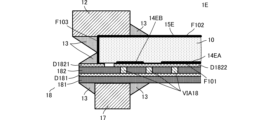
次に、図24は、流体制御装置の他の変形例の構造を示す断面図である。図25は、図24の部分拡大図である。
変形例4に係る流体制御装置1Eは、図7に示した流体制御装置1Aに対して、回路基板を備える点、および、圧電体10に形成する電極膜の形状において異なる。流体制御装置1Eの他の構成は、流体制御装置1Aと同様であり、同様の箇所の説明は省略する。
流体制御装置1Eは、圧電体10、枠体12、フィレット13、枠体17、および、回路基板18を備える。圧電体10は、主面F101、主面F102、側面F103を備える。
主面F101には、内周電極14EAおよび外周電極14EBが形成されている。外周電極14EBは、側面F103に達しない形状である。
主面F102および側面F103には、第2電極15Eが形成されている。第2電極15Eは、側面F103と主面F101との交わる角部に達する形状である。
回路基板18は、絶縁体層181、絶縁体層182の積層体を主体とする。絶縁体層181と絶縁体層182との間には、電極パターンD181が形成されている。絶縁体層182における絶縁体層181側と反対側の面には、電極パターンD1821、電極パターンD1822が形成されている。電極パターンD1821と電極パターンD1822は、互いに離間している。電極パターンD1822は、絶縁体層182に形成された複数のビア電極VIA18を通じて、電極パターンD181に電気接続される。
圧電体10は、回路基板18に実装される。圧電体10の内周電極14EAおよび外周電極14EBは、電極パターンD1822に電気接続される。圧電体10の第2電極15Eは、電極パターンD1821に電気接続される。
このような構成によって、圧電体10の内周電極14EAおよび外周電極14EBには、回路基板18の電極パターンD1822、複数のビア電極VIA18、および、電極パターンD181を通じて交流電圧が印加される。圧電体10の第2電極15Eには、電極パターンD1821を通じて交流電圧が印加される。
上述の構成によって、回路基板18は、所定の剛性(弾性)を有する平板である。したがって、回路基板18は、振動板として機能する。これにより、流体制御装置1Eは、アクチュエータを実現できる。
フィレット13は、回路基板18の電極パターンD1821、および、圧電体10の側面F103の側面F103を覆う。これにより、電極パターンD1821と枠体12との短絡を抑制できる。
このような構成によって、流体制御装置1Eは、流体制御装置1Aと同様の作用効果を奏することができる。さらに、流体制御装置1Eは、圧電体10の内周電極14EA、外周電極14EBおよび第2電極15Eに交流電圧を印加する回路基板を振動板として用いる。これにより、流体制御装置1Eは、交流電圧の印加機構を含めて、構造を簡素化できる。
なお、上述の各実施形態では、枠体の内周面が平面視して円形の場合を示したが、これに限るものではない。例えば、枠体は、内周面を平面視した形状が楕円形、正多角形でもよい。楕円形の場合は、内径は、長径を示し、正多角形の場合には、内径は対角線の長さに対応する。
同様に、各実施形態では、圧電体および振動板の外形が平面視において円形の場合を示したが、これに限るものではない。この場合、例えば、外径は、圧電体および振動板で構成されるアクチュエータに枠体を配置した状態における中心(枠体の内周面を平面視した形状の中心)からの距離が最も短いところに対応する。
本実施形態の説明は、すべての点で例示であって、制限的なものではないと考えられるべきである。本発明の範囲は、上述の実施形態ではなく、特許請求の範囲によって示される。さらに、本発明の範囲には、特許請求の範囲と均等の意味および範囲内でのすべての変更が含まれることが意図される。
1,1A,1B,1E,2,2A,2C,2D:流体制御装置
10:圧電体
10A:第1圧電体
10B:第2圧電体
11:振動板
11A:第1振動板
11B:第2振動板
11C:第3振動板
12:枠体
13:フィレット
14:第1電極
14A,14EA:内周電極
14B,14EB:外周電極
15:第2電極
15A:第2内周電極
15B:第2外周電極
17:枠体
18:回路基板
81:接合部材
82:フィルム弁
83:平板
84:流路形成部材
85:カバー部材
90:キャップ
90A:突出部
90B:開口
110A,111A:第1外周端子
110B,111B:第2外周端子
110C,111C:第3外周端子
120:曲げ端子
151:第3電極
152A:第4内周電極
152B:第4外周電極
170:曲げ端子
181,182:絶縁体層
D1821,D1822:電極パターン
VIA18:ビア電極
10:圧電体
10A:第1圧電体
10B:第2圧電体
11:振動板
11A:第1振動板
11B:第2振動板
11C:第3振動板
12:枠体
13:フィレット
14:第1電極
14A,14EA:内周電極
14B,14EB:外周電極
15:第2電極
15A:第2内周電極
15B:第2外周電極
17:枠体
18:回路基板
81:接合部材
82:フィルム弁
83:平板
84:流路形成部材
85:カバー部材
90:キャップ
90A:突出部
90B:開口
110A,111A:第1外周端子
110B,111B:第2外周端子
110C,111C:第3外周端子
120:曲げ端子
151:第3電極
152A:第4内周電極
152B:第4外周電極
170:曲げ端子
181,182:絶縁体層
D1821,D1822:電極パターン
VIA18:ビア電極
Claims (19)
- アクチュエータと、
前記アクチュエータに配置され、前記アクチュエータの外周の少なくとも一部を固定する環状の枠体と、
を備え、
前記アクチュエータは、第1主面と第2主面を有する圧電体と、前記圧電体の前記第1主面に接続される振動板と、を備え、
前記枠体は、前記第2主面に配置され、
前記振動板の外径および前記圧電体の外径が前記枠体の内径より大きく、
前記振動板の外径または前記枠体の外径が前記圧電体の外径より大きい、
流体制御装置。 - 前記枠体の側面と前記圧電体の前記第2主面、または前記枠体の側面と前記振動板の主面との間にフィレットが形成されている、
請求項1に記載の流体制御装置。 - 前記圧電体の前記第1主面に配置された電極または前記圧電体の前記第2主面に配置された電極は、平面視して、内周電極と外周電極に分割されている、
請求項1または請求項2に記載の流体制御装置。 - アクチュエータと、
前記アクチュエータに配置され、前記アクチュエータの外周の少なくとも一部を固定する環状の枠体と、
を備え、
前記アクチュエータは、第1主面と第2主面を有する圧電体と、前記圧電体に接続される振動板と、を備え、
前記振動板は、前記第1主面に接続される第1振動板と、前記第2主面に接続される第2振動板とを備え、
前記枠体は、前記第1振動板または前記第2振動板における前記圧電体と反対側の面に配置され、
前記第1振動板の外径、前記第2振動板の外径および前記圧電体の外径が前記枠体の内径より大きく、
前記第1振動板の外径、前記第2振動板の外径または前記枠体の外径が前記圧電体の外径より大きい、
流体制御装置。 - 前記枠体の側面と前記第1振動板の主面、または前記枠体の側面と前記第2振動板の主面との間にフィレットが形成されている、
請求項4に記載の流体制御装置。 - 前記圧電体の前記第1主面に配置された電極または前記圧電体の前記第2主面に配置された電極は、平面視して、内周電極と外周電極に分割されている、
請求項4または請求項5に記載の流体制御装置。 - 前記圧電体は、前記第1主面および前記第2主面を有する第1圧電体と、第3主面および第4主面を有する第2圧電体と、を含み、
前記第2振動板は、さらに前記第3主面に配置され、
前記振動板は、さらに、前記第4主面に配置される第3振動板を含み、
前記枠体は、前記第1振動板に接続される第1枠体と前記第3振動板に接続される第2枠体と、を備える、
請求項4乃至請求項6のいずれかに記載の流体制御装置。 - 平面視して、前記第1圧電体および前記第2圧電体の外径は、前記第1振動板、前記第2振動板、および前記第3振動板の外径より小さい、
請求項7に記載の流体制御装置。 - 平面視して、前記第2振動板の外径は、前記第1振動板および前記第3振動板の外径より小さい、
請求項7または請求項8に記載の流体制御装置。 - 前記第1振動板と対向する平板を備えた、
請求項7乃至請求項9のいずれかに記載の流体制御装置。 - 前記平板と前記第1振動板との間に配置される整流機構を有する、
請求項10に記載の流体制御装置。 - 前記平板と反対側で前記第3振動板に対向するキャップを備える、
請求項10に記載の流体制御装置。 - 前記キャップは開口を有する、
請求項12に記載の流体制御装置。 - 前記第1振動板、前記第2振動板、および前記第3振動板の外周側にそれぞれ突出する第1外周端子、第2外周端子、および第3外周端子を備え、
前記第1外周端子、前記第2外周端子、および前記第3外周端子は、平面視して重ならない、
請求項7乃至請求項13のいずれかに記載の流体制御装置。 - 平面視して前記流体制御装置の筐体の外径は、前記第1外周端子、前記第2外周端子、および前記第3外周端子の最も外の位置よりも外側に位置する、
請求項14に記載の流体制御装置。 - 前記第1枠体または前記第2枠体は、曲げ端子を有し、
前記第1振動板および前記第3振動板は、前記曲げ端子を介して導通している、
請求項7乃至請求項15のいずれかに記載の流体制御装置。 - 前記流体制御装置は、
前記第1振動板と対向する平板と、
前記平板と反対側で前記第3振動板に対向するキャップと、を備え、
前記キャップは、平面視して外周側に突出する突出部を備え、
前記曲げ端子は、前記突出部で押さえられている、
請求項16に記載の流体制御装置。 - 前記枠体の内側の側面と、前記第1振動板と、該第1振動板に対向する面で囲まれる空間でポンプ室が構成されている、
請求項7乃至請求項15のいずれかに記載の流体制御装置。 - 前記振動板は、回路基板で構成され、
前記回路基板は、絶縁体層と、前記圧電体の電極に接続する電極パターンと、を備える、
請求項1乃至請求項18のいずれかに記載の流体制御装置。
Applications Claiming Priority (4)
| Application Number | Priority Date | Filing Date | Title |
|---|---|---|---|
| JP2023-215780 | 2023-12-21 | ||
| JP2023215780 | 2023-12-21 | ||
| JP2024-204507 | 2024-11-25 | ||
| JP2024204507 | 2024-11-25 |
Publications (1)
| Publication Number | Publication Date |
|---|---|
| WO2025134809A1 true WO2025134809A1 (ja) | 2025-06-26 |
Family
ID=96136859
Family Applications (1)
| Application Number | Title | Priority Date | Filing Date |
|---|---|---|---|
| PCT/JP2024/043182 Pending WO2025134809A1 (ja) | 2023-12-21 | 2024-12-06 | 流体制御装置 |
Country Status (2)
| Country | Link |
|---|---|
| TW (1) | TWI912050B (ja) |
| WO (1) | WO2025134809A1 (ja) |
Families Citing this family (1)
| Publication number | Priority date | Publication date | Assignee | Title |
|---|---|---|---|---|
| CN121738865A (zh) * | 2026-02-27 | 2026-03-27 | 杭州电子科技大学 | 一种双压电驱动的气体轮式阀压电微泵及泵气方法 |
Citations (5)
| Publication number | Priority date | Publication date | Assignee | Title |
|---|---|---|---|---|
| JPH02248671A (ja) * | 1989-03-20 | 1990-10-04 | Misuzu Erii:Kk | 流体の定量圧送方法 |
| US20060232166A1 (en) * | 2005-04-13 | 2006-10-19 | Par Technologies Llc | Stacked piezoelectric diaphragm members |
| JP2009097393A (ja) * | 2007-10-16 | 2009-05-07 | Murata Mfg Co Ltd | 圧電マイクロブロア |
| JP2009293507A (ja) * | 2008-06-05 | 2009-12-17 | Alps Electric Co Ltd | 圧電ポンプ |
| US20190226471A1 (en) * | 2018-01-22 | 2019-07-25 | Microjet Technology Co., Ltd. | Fluid system |
Family Cites Families (5)
| Publication number | Priority date | Publication date | Assignee | Title |
|---|---|---|---|---|
| JP2001119795A (ja) * | 1999-08-10 | 2001-04-27 | Murata Mfg Co Ltd | 圧電型電気音響変換器 |
| US7198250B2 (en) * | 2000-09-18 | 2007-04-03 | Par Technologies, Llc | Piezoelectric actuator and pump using same |
| CN102046978B (zh) * | 2008-06-03 | 2013-11-20 | 株式会社村田制作所 | 压电微型鼓风机 |
| JP5962848B2 (ja) * | 2013-03-22 | 2016-08-03 | 株式会社村田製作所 | 圧電ブロア |
| JP7349090B2 (ja) * | 2019-05-21 | 2023-09-22 | 日清紡マイクロデバイス株式会社 | 圧電素子 |
-
2024
- 2024-12-06 WO PCT/JP2024/043182 patent/WO2025134809A1/ja active Pending
- 2024-12-06 TW TW113147447A patent/TWI912050B/zh active
Patent Citations (5)
| Publication number | Priority date | Publication date | Assignee | Title |
|---|---|---|---|---|
| JPH02248671A (ja) * | 1989-03-20 | 1990-10-04 | Misuzu Erii:Kk | 流体の定量圧送方法 |
| US20060232166A1 (en) * | 2005-04-13 | 2006-10-19 | Par Technologies Llc | Stacked piezoelectric diaphragm members |
| JP2009097393A (ja) * | 2007-10-16 | 2009-05-07 | Murata Mfg Co Ltd | 圧電マイクロブロア |
| JP2009293507A (ja) * | 2008-06-05 | 2009-12-17 | Alps Electric Co Ltd | 圧電ポンプ |
| US20190226471A1 (en) * | 2018-01-22 | 2019-07-25 | Microjet Technology Co., Ltd. | Fluid system |
Also Published As
| Publication number | Publication date |
|---|---|
| TWI912050B (zh) | 2026-01-11 |
| TW202526172A (zh) | 2025-07-01 |
Similar Documents
| Publication | Publication Date | Title |
|---|---|---|
| US11598330B2 (en) | Fluid control device and pump | |
| JP4497321B2 (ja) | 圧電アクチュエータ | |
| US7586241B2 (en) | Electroacoustic transducer | |
| US6741710B1 (en) | Piezoelectric electroacoustic transducer | |
| US12302061B2 (en) | Transducer | |
| WO2012140967A1 (ja) | アクチュエータ支持構造およびポンプ装置 | |
| US10972840B2 (en) | Speaker | |
| CN106576209A (zh) | 电声转换装置 | |
| JP3770111B2 (ja) | 圧電型電気音響変換器 | |
| TWI912050B (zh) | 流體控制裝置 | |
| JP7485212B2 (ja) | アクチュエータ、ポンプ、アクチュエータの製造方法 | |
| EP2693771B1 (en) | Oscillator and electronic device | |
| WO2025134808A1 (ja) | アクチュエータ | |
| WO2018061805A1 (ja) | 圧電式マイクロフォン | |
| WO2020136983A1 (ja) | 圧電トランスデューサ | |
| WO2018190200A1 (ja) | スピーカ素子及びアレイスピーカ | |
| JP7671163B2 (ja) | 音響デバイス | |
| WO2022118575A1 (ja) | トランスデューサ | |
| JP7550066B2 (ja) | 振動デバイス | |
| JP7663415B2 (ja) | 音響デバイス | |
| JP2022184332A (ja) | 振動デバイス | |
| JP7710845B2 (ja) | 振動デバイス及び圧電振動子 | |
| JP5871753B2 (ja) | 音響発生器、音響発生装置および電子機器 | |
| JP2026084385A (ja) | アクチュエータ | |
| CN114746650B (zh) | 致动器以及流体控制装置 |
Legal Events
| Date | Code | Title | Description |
|---|---|---|---|
| 121 | Ep: the epo has been informed by wipo that ep was designated in this application |
Ref document number: 24907195 Country of ref document: EP Kind code of ref document: A1 |
|
| ENP | Entry into the national phase |
Ref document number: 2025565239 Country of ref document: JP Kind code of ref document: A |
|
| WWE | Wipo information: entry into national phase |
Ref document number: 2025565239 Country of ref document: JP |