WO2025120802A1 - Scadaウェブhmiシステム - Google Patents
Scadaウェブhmiシステム Download PDFInfo
- Publication number
- WO2025120802A1 WO2025120802A1 PCT/JP2023/043828 JP2023043828W WO2025120802A1 WO 2025120802 A1 WO2025120802 A1 WO 2025120802A1 JP 2023043828 W JP2023043828 W JP 2023043828W WO 2025120802 A1 WO2025120802 A1 WO 2025120802A1
- Authority
- WO
- WIPO (PCT)
- Prior art keywords
- address
- screen
- hmi
- existing
- diversion
- Prior art date
- Legal status (The legal status is an assumption and is not a legal conclusion. Google has not performed a legal analysis and makes no representation as to the accuracy of the status listed.)
- Pending
Links
Images







Classifications
-
- G—PHYSICS
- G05—CONTROLLING; REGULATING
- G05B—CONTROL OR REGULATING SYSTEMS IN GENERAL; FUNCTIONAL ELEMENTS OF SUCH SYSTEMS; MONITORING OR TESTING ARRANGEMENTS FOR SUCH SYSTEMS OR ELEMENTS
- G05B19/00—Program-control systems
- G05B19/02—Program-control systems electric
- G05B19/04—Program control other than numerical control, i.e. in sequence controllers or logic controllers
- G05B19/05—Programmable logic controllers, e.g. simulating logic interconnections of signals according to ladder diagrams or function charts
-
- G—PHYSICS
- G06—COMPUTING OR CALCULATING; COUNTING
- G06F—ELECTRIC DIGITAL DATA PROCESSING
- G06F8/00—Arrangements for software engineering
- G06F8/30—Creation or generation of source code
- G06F8/38—Creation or generation of source code for implementing user interfaces
-
- G—PHYSICS
- G06—COMPUTING OR CALCULATING; COUNTING
- G06F—ELECTRIC DIGITAL DATA PROCESSING
- G06F9/00—Arrangements for program control, e.g. control units
- G06F9/06—Arrangements for program control, e.g. control units using stored programs, i.e. using an internal store of processing equipment to receive or retain programs
-
- G—PHYSICS
- G06—COMPUTING OR CALCULATING; COUNTING
- G06F—ELECTRIC DIGITAL DATA PROCESSING
- G06F9/00—Arrangements for program control, e.g. control units
- G06F9/06—Arrangements for program control, e.g. control units using stored programs, i.e. using an internal store of processing equipment to receive or retain programs
- G06F9/44—Arrangements for executing specific programs
- G06F9/451—Execution arrangements for user interfaces
Definitions
- the present invention relates to a SCADA web HMI system.
- SCADA Supervisory Control and Data Acquisition
- Social infrastructure systems include, for example, steel rolling systems, power transmission and transformation systems, water and sewerage treatment systems, building management systems, and road systems.
- SCADA is a type of industrial control system that uses computers to monitor systems and control processes. SCADA requires responsiveness (real-time performance) that matches the processing performance of the system.
- SCADA has the following subsystems: HMI (Human Machine Interface), a monitoring and control system, a remote input/output device (RIO), and a communications infrastructure.
- HMI Human Machine Interface
- RIO remote input/output device
- HMI is a mechanism that displays data on the target process (monitored device) and parts such as operation buttons (also called “operation parts” or “items”) on the HMI screen, allowing an operator to monitor the process and operate the operation buttons to control the target process.
- the monitoring and control system collects signal data (PLC signals) on the process and sends control commands to the process.
- PLC signals signal data
- the monitoring and control system is composed of PLCs (Programmable Logic Controllers).
- the remote input/output device connects to sensors installed in the process, converts the sensor signals into digital data, and sends the digital data to the monitoring and control system.
- the communications infrastructure connects the monitoring and control system to the remote input/output devices.
- the design support device described in Patent Document 1 has a function to automatically assign addresses for sending and receiving operation signals and display signals between a monitoring control system (PLC) and an HMI connected via a network.
- PLC monitoring control system
- the present disclosure has been made to solve the problems described above.
- the purpose of this disclosure is to provide a SCADA Web HMI system that, when adding or modifying an HMI screen, does not require changes to the PLC software when adding only new parts that perform the same processing as existing parts, reduces the designer's work time, and can minimize the address area used within the PLC and the amount of data sent to and received from the PLC.
- the first aspect relates to a SCADA web HMI system.
- the SCADA web HMI system updates the display state of at least one part displayed on an HMI screen on a web browser based on a display signal corresponding to a signal received from a PLC, and is capable of transmitting an operation signal corresponding to an operation of at least one part to the PLC.
- the SCADA web HMI system includes an HMI design device that creates multiple HMI screens, and the HMI design device has an address allocation means that executes address allocation for all parts on the created HMI screen.
- the SCADA web HMI system includes an address diversion source designation means and an address diversion means.
- the existing HMI screen is the first screen
- the HMI screen to be added or modified is the second screen
- the parts of the first screen are existing parts
- the parts of the second screen are new parts.
- the address diversion source designation means designates the existing part that is the address diversion source for the new part that is the address diversion destination.
- the address diversion means is a means for specifying an existing part as the address diversion source for the new part by the address diversion source designation means, and for the new part and the existing part to perform the same processing, and when an address has already been assigned to the existing part by the address allocation means, diverts the address of the existing part to the new part.
- the web browser displays the HMI screen, updates the display of the existing part on the first screen and the new part on the second screen based on a common display signal, and transmits an operation signal according to the operation of the existing part and the new part to the common address of the PLC.
- the second viewpoint has the following feature in addition to the first viewpoint:
- the existing component and the new component are display components that update the display state on the first screen and the second screen based on a display signal, or operation components for sending an operation signal to the PLC.
- the third aspect has the following characteristics in addition to the first or second aspect:
- the SCADA web HMI system further includes an address diversion result generating means for generating address diversion information that describes the part names of existing parts and the part names of new parts.
- addresses common to existing parts can be reused and assigned to new parts that perform the same processing as existing parts. This eliminates the need to implement processing in the PLC software to operate new parts, and allows new parts to operate based on the addresses of existing parts. This makes it possible to change only the HMI screen without changing the PLC software, thereby reducing the designer's work time. Furthermore, the address area used within the PLC and the amount of data sent to and received from the PLC can be kept to a necessary minimum.
- FIG. 1 is a diagram showing a configuration of a SCADA web HMI system according to an embodiment.
- 2 is a block diagram showing an example of the hardware configuration of a SCADA web HMI design device and a SCADA web HMI execution device;
- FIG. 2 is a block diagram for explaining main processes executed in an engineering tool and a web browser.
- FIG. 13 is a diagram showing an example of a drawing creation screen displayed by an engineering tool.
- 1A and 1B are diagrams showing an example of a first screen and a second screen which are HMI screens created by a drawing process.
- Fig. 6(a) is a diagram showing an example of on-screen part information of the first screen shown in Fig. 5.
- FIG. 6(b) is a diagram showing an example of on-screen part information of the second screen shown in Fig. 5.
- FIG. 13 is a diagram showing an example of in-screen part information of the 2nd screen after the address diversion source is input; 11 is a flowchart for explaining the flow of an address allocation process 14.
- FIG. 11 illustrates an example of an allocation processing rule.
- FIG. 13 is a diagram showing an example of in-screen part information of the first screen after the address allocation process is executed.
- FIG. 13 is a diagram showing an example of in-screen part information of the 2nd screen after the address allocation process and the address diversion process are executed;
- FIG. 13 is a diagram illustrating an example of address diversion information generated after executing an address diversion process.
- ⁇ Overall System> 1 is a diagram showing the configuration of a SCADA web HMI system according to an embodiment.
- the SCADA web HMI system includes a SCADA web HMI design device (hereinafter also referred to as "HMI design device") 1, which is an HMI development environment.
- the SCADA web HMI system includes, as subsystems, a SCADA web HMI execution device (hereinafter also referred to as HMI execution device) 3, which is an HMI execution environment, a monitoring and control system 4, a communication infrastructure 5, a remote input/output device (RIO) 6, and a monitored device 7.
- HMI design device SCADA web HMI design device
- the monitoring and control system 4 includes a programmable logic controller (PLC) that has an internal address area 41.
- PLC programmable logic controller
- the communication infrastructure 5 connects the monitoring and control system 4 to a remote input/output device.
- the remote input/output device 6 connects to a sensor installed in the monitored device 7, converts the sensor signal into digital data, and sends the digital data to the monitoring and control system 4.
- the monitored device 7 is the sensors, actuators, etc. that make up the plant.
- the HMI design device 1 executes an engineering tool 10.
- the engineering tool 10 has a function for creating and editing drawings, a function for saving drawing data in SVG (Scalable Vector Graphics) format, and an extended function.
- the drawing creation and editing function and the SVG data saving function are realized, for example, by Microsoft Visio (registered trademark).
- the HMI design device 1 is equipped with a GUI as a user interface for executing the engineering tool 10.
- the engineering tool 10 generates interface information 21 and HMI screen data 22 required for functioning an HMI execution device 3, which is an HMI execution environment.
- the interface information 21 and the HMI screen data 22 constitute web HMI data 2.
- FIG. 2 is a block diagram showing an example of the hardware configuration of the SCADA web HMI design device 1 and the SCADA web HMI execution device 3.
- FIG. 3 is a block diagram for explaining the main processes executed in the engineering tool 10 and the web browser 32.
- the processes of the HMI design device 1, which will be described later, are realized by the processing circuit shown in FIG. 2.
- the processing circuit is configured by connecting at least one processor 1a, memory 1b, display 1c, and input/output interface 1d.
- Memory 1b stores programs that describe the processes executed by the engineering tool 10.
- Input/output interface 1d includes input devices such as a keyboard and a mouse, and an output device that can output web HMI data 2 as a file.
- Processor 1a realizes the processes of the HMI design device 1, which will be described later, by executing the programs read from memory 1b.
- the engineering tool 10 can execute the following main processes: drawing process 11, component data generation process 12, in-screen component information generation process 13, address allocation process 14, interface information generation process 15, and HMI screen data generation process 16. Each process executed by the engineering tool 10 will be explained below.
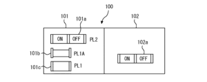
- FIG. 4 is a diagram showing an example of a drawing creation screen 100 displayed by the engineering tool 10.
- the drawing creation screen 100 is displayed on the display 1c.
- the drafting process 11 displays, on the drawing creation screen 100, a stencil area 101 in which prototypes (master shapes) 101a, 101b, 101c of multiple parts required to create a drawing are arranged, and a drafting area 102 in which a drawing for an HMI screen is drawn.
- the designer operates the input/output interface 1d to select a prototype from the stencil area 101 and place the selected prototype in the drafting area 102.
- the prototype 101a of a two-choice button item in the stencil area 101 is dragged and dropped into the drafting area 102, thereby placing the two-choice button item 102a in the drafting area 102.
- FIG. 5 is a diagram showing an example of a first screen G100 and a second screen G200, which are HMI screens created by a drawing process.
- a two-choice button item 111 is arranged on the first screen G100, and a two-choice button item 112 is arranged on the second screen G200 in a position different from that of the first screen G100.
- the first screen G100 corresponds to an existing screen in the scope of the claims
- the second screen G200 corresponds to a new screen in the scope of the claims.
- the two-choice button item 111 corresponds to an existing part in the scope of the claims
- the two-choice button item 112 corresponds to a new part in the scope of the claims.
- the part data generation process 12 automatically generates unique part data when a part is placed in the drawing area 102 shown in Fig. 4.
- the part data is data that associates the placement information of the part placed in the drawing area 102 with the part identifier, attribute identifier, and part type.
- the placement information is static screen display data such as the shape, position, and size of a part placed in the drawing area 102, and is information in which the appearance of the part does not change regardless of the value of the received PLC signal.
- the placement information can be changed in the drawing area 102.
- the part identifier is a unique identifier that identifies each part placed on a single drawing, such as a part number.
- the attribute identifier is an identifier that indicates the dynamic display attribute of the part.
- the part data generation process 12 generates a "part name” by combining the screen identifier G100, G200 of the HMI screen and the part identifier 1PL2, and generates an "item name” by combining the part name and the attribute identifier.
- the item name is unique in the SCADA web HMI system.
- the part data generation process 12 generates one "part type” for each part. For example, a part type called “PL” is generated for an operation part, and a part type called “SL” is generated for a lamp display part.
- Fig. 6(a) is a diagram showing an example of on-screen part information 131 of the first screen G100 shown in Fig. 5.
- Fig. 6(b) is a diagram showing an example of on-screen part information 132 of the second screen G200 shown in Fig. 5.
- the on-screen component information generation process 13 is executed when component data is generated by the component data generation process 12.
- the on-screen component information generation process 13 generates on-screen component information 131, 132 in tabular form for each screen G100, G200.
- the on-screen component information 131, 132 describes, for each component, the component name, component type, and item names of the operation signal and display signal.
- the addresses of the operation signal and display signal are described after execution of the address allocation process 14 described below.
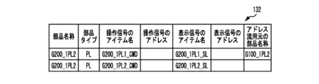
- FIG. 7 is a diagram showing an example of the in-screen part information 132 of the second screen G200 after the part name of the first screen G100 has been input as the address reuse source.
- the "address diversion source part name" is specified for each part in order to associate the address diversion source part.
- the in-screen part information 132 of the second screen G200 is edited, and the part name of the operation part placed on the first screen G100, "G100_1PL2", is entered in the address diversion source part name field.
- the address diversion destination part name "G200_1PL2” and the address flow source part name "G100_1PL2" are the same part type PL and perform the same processing. Performing the same processing means being linked to the same operation signal or display signal.
- the address allocation process 14 is executed by the designer of the HMI screen.
- the address allocation process 14 allocates addresses to all components of each of the screens G100, G200.
- Figure 8 is a flow chart for explaining the flow of the address allocation process 14.
- Figure 9 is a diagram showing an example of an allocation process rule 141.
- Figure 10 is a diagram showing an example of in-screen component information 131 of the first screen G100 after the address allocation process 14 has been executed.
- the address allocation process 14 corresponds to the "address allocation means" in the claims.
- the on-screen component information 131, 132 generated by the on-screen component information generation process 13 is read (step S10).
- the number of component names in the on-screen component information G100, G200 is substituted into the variable N, and "1" is substituted into the counter variable i as an initial value (step S11).
- the allocation processing rule 141 for allocating addresses is read (step S12).
- the allocation processing rule 141 defines the association between the number of bits of the operation signal and the number of bits of the display signal for each component type. In the example shown in FIG. 9, the number of bits of the operation signal and the number of bits of the display signal corresponding to the component type are defined.
- the engineering tool 10 has the allocation processing rule 141.
- the allocation processing rule 141 is stored in memory 1b.
- step S13 it is determined whether the value of counter variable i is less than N (step S13). If the value of counter variable i is less than N, it is determined whether an address diversion source has been specified (step S14). If an address diversion source has been specified, the process proceeds to step S17, which will be described later, and address diversion processing 140, which will be described later, is executed. If an address diversion source has not been specified, the process proceeds to step S15.
- the process of step S14 corresponds to the "address diversion source designation means" in the claims.
- step S15 an address is assigned from the on-screen component information corresponding to the i-th component name among the on-screen component information 131, 132, based on the allocation processing rule 141. Specifically, from the on-screen component information corresponding to the i-th component name, an address is assigned to the operation signal transmitted from the SCADA web HMI execution device 3 to the monitoring and control system (PLC) 4, based on the number of bits of the operation signal and the number of bits of the display signal contained in the allocation processing rule 141 read out in step S12 above, and an address is assigned to the display signal transmitted from the monitoring and control system (PLC) 4 to the SCADA web HMI execution device 3. Then, i+1 is substituted for the variable i, and the process returns to step S13.
- PLC monitoring and control system
- Address information generation process 14 can be executed for each of screens G100 and G200.
- addresses are assigned to operation signal item names "G100_1PL1_CMD” and “G100_1PL2_CMD” of part name "G100_1PL2” and display signal item names "G100_1PL1_SL” and "G100_1PL2_SL” based on assignment process rule 141.
- the address information generation process 14 has an address diversion process 140 that includes steps S17 to S24. As shown in FIG. 2, the address diversion process 140 is executed as part of the address information generation process 14. The address diversion process 140 can divert an address from an operation item placed on the first screen G100 to an operation item on the second screen G200.
- the address information diversion process 140 will be described with reference to Figures 11 and 12.
- the address information diversion process 140 corresponds to the "address diversion source designation means" and the "address diversion means" in the claims.
- the address information reuse process 140 is executed when it is determined in step S13 that the value of the counter variable i is less than N, and when it is determined in step S14 that the address reuse source has been specified.
- step S17 it is determined whether the part type of the address source and the part type of the address destination are the same based on the on-screen part information. If the part type of the address source and the part type of the address destination are different, the process proceeds to step S22, where an error message is displayed, and the routine ends. If the part types are the same, the process proceeds to step S18.
- step S18 it is determined whether or not an address has already been assigned to the component from which the address is to be used, based on the in-screen component information 131 of the first screen G100. If an address has not been assigned to the component from which the address is to be used, the process proceeds to step S22. If an address has been assigned to the component from which the address is to be used, the process proceeds to step S19.
- step S19 the same address as the part from which the address was reused is assigned to the part to which the address is reused.
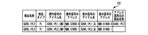
- FIG. 11 is a diagram showing an example of in-screen part information 132 for the second screen G200 after execution of address information generation process 14 and address reuse process 140. As shown in FIG. 11, an address that is the same as the address assigned to the part on the first screen G100 is assigned to the part on the second screen G200.
- address reuse process 140 in address information generation process 14 the part name "G100_1PL2" from which the address was reused is used to associate each part with the part from which the address was reused.
- step S20 the number of part names whose addresses have been reused is substituted for variable k (step S20).
- i+k is substituted for variable i (step S21), and the process returns to step S13. If the address allocation process 14 is continued and it is determined in step S13 that the value of counter variable i is equal to or greater than N, the process proceeds to step S23.
- step S23 as shown in Figs. 10 and 11, the address allocation result is added to the on-screen component information 131, 132.
- address diversion information is generated (step S24).
- Fig. 12 is a diagram showing an example of address diversion information 142 generated after executing address diversion process 140.
- the address diversion information 142 makes it possible to associate and store the part name of the address diversion source and the part name of the address diversion destination.
- the process of step S24 corresponds to the "address diversion result generating means" in the claims. After step S24, this routine ends.
- the interface information 21 is information that defines the relationship between the item names and addresses of operation signals transmitted from the SCADA web HMI execution device 3 to the supervisory control system (PLC) 4 and display signals transmitted from the supervisory control system (PLC) 4 to the SCADA web HMI execution device 3.
- the HMI screen data generation process 16 generates HMI screen data 22 in a format readable by the SCADA web HMI execution device 3 based on the layout information of each part generated by the part data generation process 12 .
- the web HMI data 2 which includes the interface information 21 and HMI screen data 22 generated by the engineering tool 10 in this way, is information that can be read by the SCADA web HMI execution device 3.
- the SCADA web HMI execution device 3 updates the display of HMI screens such as the first screen G100 and the second screen G200 based on the web HMI data 2. Specifically, it updates the display of the HMI screen based on the HMI screen data 22, which is static information such as the shape, position, and size of the parts, and the values received from the PLC 4, which is dynamic information.
- the address information assigned to the display items and operation items of each part in the HMI screen is defined by the interface information 21.
- the processing of the HMI execution device 3 is realized by a processing circuit shown in Fig. 2.
- the processing circuit includes at least one processor 3a, a memory 3b, a display 3c, an input/output interface 3d, and a network interface 3e.
- the memory 3b stores a program describing the processing executed by the HMI execution device 3.
- the input/output interface 3d includes input devices such as a keyboard and a mouse, and a device capable of reading the web HMI data 2 (interface information 21 and HMI screen data 22).
- the network interface 3e is a device that is connected to the monitoring and control system 4 and is capable of transmitting and receiving signal data and control commands.
- the processor 3a executes the program read from the memory 3b to realize each processing of the HMI execution device 3, which will be described later.
- the web server 31 reads the web HMI data 2.
- the web server 31 arranges the interface information 21 and the HMI screen data 22 of the web HMI data 2 as HMI web runtime contents, and makes it possible to transmit and receive signals between the web browser 32 and the monitoring and control system (PLC) 4.
- PLC monitoring and control system
- the process of the HMI server runtime 311 running on the web server 31 is as follows. That is, the HMI server runtime 311 has an application server built in, and supplies HMI web runtime content to the web browser 32.
- the HMI server runtime 311 communicates with the monitoring and control system 4 (PLC), and when a PLC signal received from the monitoring and control system 4 is a signal related to the HMI screen currently being displayed on the web browser 32, it transmits the PLC signal to the web browser 32.
- PLC monitoring and control system 4
- the HMI server runtime 311 transmits signal data from the monitored device 7 to the HMI web runtime 321, and also transmits control commands from the HMI web runtime 321 to the monitoring and control system 4.
- the process of the web browser 32 will be described with reference to Fig. 3.
- the web browser 32 reads the web HMI data 2 (interface information 21 and HMI screen data 22) and displays an HMI screen for monitoring the plant on the web browser 32.
- On the HMI screen parts for displaying the state of the monitored device 7 and parts for operating the monitored device 7 via the monitoring control system 4 are arranged.
- the web browser 32 can display and update the HMI screen in response to a signal received from the monitoring control system (PLC) 4.
- PLC monitoring control system
- the web browser 32 changes the appearance of the parts arranged on the HMI screen in response to the value of the PLC signal received from the monitoring control system 4 via the web server 31.
- the two-choice buttons 111, 112 arranged on the first screen G100 and the second screen G200 displayed as HMI screens operate based on address information written in the interface information 21.
- address information is defined by the address reuse process 140 described above for the operation signal from the HMI execution device 3 to the supervisory control system (PLC) 4 and the display signal from the supervisory control system (PLC) 4 to the SCADA web HMI execution device 3.
- the address allocation process 14 has the address reuse process 140, so that addresses common to existing parts can be reused and assigned to new parts that perform the same processing as existing parts. This eliminates the need to implement processing for operating new parts in the PLC software, and the new parts can be operated based on the addresses of existing parts. This makes it possible to change only the second screen G200 without changing the PLC software, thereby reducing the designer's work time. Furthermore, the address area 41 used inside the PLC 4 and the amount of data sent to and received from the PLC 4 can be kept to a necessary minimum.
- the present disclosure is not limited to the above embodiments, and various modifications can be made without departing from the spirit of the present disclosure.
- the above embodiments have been described with reference to an example in which a second screen G200 separate from an existing first screen G100 is newly created (added), but the present disclosure can also be applied to a case in which the first screen G100 is modified to create the second screen G200.
- drawing data in SVG format is used, but the format of the drawing data is not limited to this. If the web browser 32 supports WebGL, the drawing data may be in a format compatible with WebGL.
- the HMI execution device 3 is equipped with a web server 31 and a web browser 32, but it may also be configured so that multiple client terminals are connected to the web server 31 and the web browser 32 is displayed on the display of each client terminal.
- 1...HMI design device 1d...input/output interface (address diversion source designation means), 10...engineering tool, 11...drawing process, 12...part data generation process, 13...in-screen part information generation process, 14...address allocation process (address allocation means), 140...address diversion process (address diversion source designation means, address diversion means), 142...address diversion information, 15...interface information generation process, 16...HMI screen data generation process, 3...HMI execution device, 32...web browser, 4...monitoring control system (PLC), 41...address area, 7...monitoring target device, G100...first screen, existing screen, HMI screen, 111...two-way button item (existing part), G200...second screen, new screen, HMI screen, 112...two-way button item (new part)
Landscapes
- Engineering & Computer Science (AREA)
- Software Systems (AREA)
- Theoretical Computer Science (AREA)
- Physics & Mathematics (AREA)
- General Physics & Mathematics (AREA)
- General Engineering & Computer Science (AREA)
- Human Computer Interaction (AREA)
- Automation & Control Theory (AREA)
- Programmable Controllers (AREA)
Priority Applications (5)
| Application Number | Priority Date | Filing Date | Title |
|---|---|---|---|
| CN202380084903.XA CN120457411A (zh) | 2023-12-07 | 2023-12-07 | Scada网页hmi系统 |
| JP2025518209A JP7790634B2 (ja) | 2023-12-07 | 2023-12-07 | Scadaウェブhmiシステム |
| PCT/JP2023/043828 WO2025120802A1 (ja) | 2023-12-07 | 2023-12-07 | Scadaウェブhmiシステム |
| KR1020257040649A KR20260003827A (ko) | 2023-12-07 | 2023-12-07 | Scada 웹 hmi 시스템 |
| TW113122549A TWI916859B (zh) | 2023-12-07 | 2024-06-18 | Scada web hmi系統 |
Applications Claiming Priority (1)
| Application Number | Priority Date | Filing Date | Title |
|---|---|---|---|
| PCT/JP2023/043828 WO2025120802A1 (ja) | 2023-12-07 | 2023-12-07 | Scadaウェブhmiシステム |
Publications (1)
| Publication Number | Publication Date |
|---|---|
| WO2025120802A1 true WO2025120802A1 (ja) | 2025-06-12 |
Family
ID=95979575
Family Applications (1)
| Application Number | Title | Priority Date | Filing Date |
|---|---|---|---|
| PCT/JP2023/043828 Pending WO2025120802A1 (ja) | 2023-12-07 | 2023-12-07 | Scadaウェブhmiシステム |
Country Status (4)
| Country | Link |
|---|---|
| JP (1) | JP7790634B2 (https=) |
| KR (1) | KR20260003827A (https=) |
| CN (1) | CN120457411A (https=) |
| WO (1) | WO2025120802A1 (https=) |
Citations (3)
| Publication number | Priority date | Publication date | Assignee | Title |
|---|---|---|---|---|
| WO2005101147A1 (ja) * | 2004-04-15 | 2005-10-27 | Mitsubishi Denki Kabushiki Kaisha | プログラマブルロジックコントローラの周辺装置及びそのプログラム作成方法 |
| JP2014142778A (ja) * | 2013-01-23 | 2014-08-07 | Toshiba Mitsubishi-Electric Industrial System Corp | 鉄鋼プラントエンジニアリング支援装置 |
| WO2023281662A1 (ja) * | 2021-07-07 | 2023-01-12 | 東芝三菱電機産業システム株式会社 | Scadaウェブhmiシステム |
Family Cites Families (2)
| Publication number | Priority date | Publication date | Assignee | Title |
|---|---|---|---|---|
| JP5156713B2 (ja) | 2009-10-02 | 2013-03-06 | 東芝三菱電機産業システム株式会社 | 設計支援装置 |
| JP5518689B2 (ja) | 2010-12-08 | 2014-06-11 | 株式会社デジタル | 作画装置及び作画プログラム |
-
2023
- 2023-12-07 WO PCT/JP2023/043828 patent/WO2025120802A1/ja active Pending
- 2023-12-07 KR KR1020257040649A patent/KR20260003827A/ko active Pending
- 2023-12-07 JP JP2025518209A patent/JP7790634B2/ja active Active
- 2023-12-07 CN CN202380084903.XA patent/CN120457411A/zh active Pending
Patent Citations (3)
| Publication number | Priority date | Publication date | Assignee | Title |
|---|---|---|---|---|
| WO2005101147A1 (ja) * | 2004-04-15 | 2005-10-27 | Mitsubishi Denki Kabushiki Kaisha | プログラマブルロジックコントローラの周辺装置及びそのプログラム作成方法 |
| JP2014142778A (ja) * | 2013-01-23 | 2014-08-07 | Toshiba Mitsubishi-Electric Industrial System Corp | 鉄鋼プラントエンジニアリング支援装置 |
| WO2023281662A1 (ja) * | 2021-07-07 | 2023-01-12 | 東芝三菱電機産業システム株式会社 | Scadaウェブhmiシステム |
Also Published As
| Publication number | Publication date |
|---|---|
| JP7790634B2 (ja) | 2025-12-23 |
| CN120457411A (zh) | 2025-08-08 |
| TW202526533A (zh) | 2025-07-01 |
| KR20260003827A (ko) | 2026-01-07 |
| JPWO2025120802A1 (https=) | 2025-06-12 |
Similar Documents
| Publication | Publication Date | Title |
|---|---|---|
| AU2017249034B2 (en) | Apparatus and method for generating industrial process graphics | |
| US8825183B2 (en) | Methods for a data driven interface based on relationships between process control tags | |
| JP6751551B2 (ja) | 汎用プロセスシステムライブラリに基づきプロセス制御システムを構成する方法および装置 | |
| JP6552775B1 (ja) | ハイブリッドレンダリングhmi端末装置 | |
| JPWO2013191275A1 (ja) | 制御装置 | |
| CA2858054A1 (en) | Systems and methods for batch device commissioning and decommissioning | |
| WO2020090033A1 (ja) | SCADA Web HMIシステム | |
| US11281650B2 (en) | Control system, controller, and control method | |
| US12032358B2 (en) | SCADA web HMI system | |
| JP7790634B2 (ja) | Scadaウェブhmiシステム | |
| CN112286511B (zh) | 配置工业自动化部件的方法及工业自动化部件 | |
| JP2022125962A (ja) | プロセス制御システム用の実装可能なシーケンシャルファンクションチャートコードを生成するための方法、システム、およびコンピュータプログラム製品 | |
| TWI916859B (zh) | Scada web hmi系統 | |
| CN111651142B (zh) | 一种组态型示教器管理系统 | |
| CN115202650A (zh) | 编程支持设备 | |
| JP4778312B2 (ja) | データ処理装置、プログラム、エディタ装置および記録媒体 | |
| JPWO2018179206A1 (ja) | システム設計支援装置およびシステム設計支援方法 | |
| JP7793401B2 (ja) | プロトコルドライバ作成装置 | |
| US20260029775A1 (en) | Supporting an undefined data type | |
| WO2024171267A1 (ja) | Hmi画面設計装置及びscadaウェブhmiシステム | |
| WO2025009169A1 (ja) | 変換装置、中継装置、制御装置、及び制御システム | |
| JPWO2025120802A5 (https=) | ||
| JP2024136415A (ja) | 制御システム、サポート装置、および制御装置 | |
| JPH04235602A (ja) | アドレス変換テーブル作成方法 | |
| WO2018185854A1 (ja) | 経路情報生成装置、経路情報生成方法およびプログラム |
Legal Events
| Date | Code | Title | Description |
|---|---|---|---|
| ENP | Entry into the national phase |
Ref document number: 2025518209 Country of ref document: JP Kind code of ref document: A |
|
| WWE | Wipo information: entry into national phase |
Ref document number: 2025518209 Country of ref document: JP |
|
| WWE | Wipo information: entry into national phase |
Ref document number: 202517055622 Country of ref document: IN |
|
| WWE | Wipo information: entry into national phase |
Ref document number: 202380084903.X Country of ref document: CN |
|
| WWP | Wipo information: published in national office |
Ref document number: 202517055622 Country of ref document: IN |
|
| 121 | Ep: the epo has been informed by wipo that ep was designated in this application |
Ref document number: 23960815 Country of ref document: EP Kind code of ref document: A1 |
|
| WWP | Wipo information: published in national office |
Ref document number: 202380084903.X Country of ref document: CN |
|
| ENP | Entry into the national phase |
Ref document number: 1020257040649 Country of ref document: KR Free format text: ST27 STATUS EVENT CODE: A-0-1-A10-A15-NAP-PA0105 (AS PROVIDED BY THE NATIONAL OFFICE) |
|
| WWE | Wipo information: entry into national phase |
Ref document number: 1020257040649 Country of ref document: KR |
|
| WWP | Wipo information: published in national office |
Ref document number: 1020257040649 Country of ref document: KR |