WO2025115263A1 - ロータおよび回転電機 - Google Patents
ロータおよび回転電機 Download PDFInfo
- Publication number
- WO2025115263A1 WO2025115263A1 PCT/JP2024/022331 JP2024022331W WO2025115263A1 WO 2025115263 A1 WO2025115263 A1 WO 2025115263A1 JP 2024022331 W JP2024022331 W JP 2024022331W WO 2025115263 A1 WO2025115263 A1 WO 2025115263A1
- Authority
- WO
- WIPO (PCT)
- Prior art keywords
- rotor
- slot
- radially
- conductor
- circumferential
- Prior art date
- Legal status (The legal status is an assumption and is not a legal conclusion. Google has not performed a legal analysis and makes no representation as to the accuracy of the status listed.)
- Pending
Links
Images


Classifications
-
- H—ELECTRICITY
- H02—GENERATION; CONVERSION OR DISTRIBUTION OF ELECTRIC POWER
- H02K—DYNAMO-ELECTRIC MACHINES
- H02K1/00—Details of the magnetic circuit
- H02K1/06—Details of the magnetic circuit characterised by the shape, form or construction
- H02K1/22—Rotating parts of the magnetic circuit
- H02K1/26—Rotor cores with slots for windings
-
- H—ELECTRICITY
- H02—GENERATION; CONVERSION OR DISTRIBUTION OF ELECTRIC POWER
- H02K—DYNAMO-ELECTRIC MACHINES
- H02K17/00—Asynchronous induction motors; Asynchronous induction generators
- H02K17/02—Asynchronous induction motors
- H02K17/16—Asynchronous induction motors having rotors with internally short-circuited windings, e.g. cage rotors
Definitions
- the present invention relates to a rotor and a rotating electric machine.
- JP 2016-171627 discloses a structure in which a convex part that protrudes in the circumferential direction is provided on the inner surface of each slot formed in a rotor core, and the convex part receives the centrifugal force applied to the conductor part.
- one of the objects of the present invention is to provide a rotor and a rotating electric machine that can suppress deformation of the rotor core while suppressing the detachment of the conductive parts from the slots due to centrifugal force.
- One aspect of the rotor of the present invention is a rotor for a rotating electric machine that rotates about a central axis, and includes a rotor core having a plurality of slots that are arranged in the circumferential direction and penetrate the axial direction, a plurality of conductor parts arranged in the slots, and a pair of end rings located on one axial side and the other axial side of the rotor core, respectively, and connecting the plurality of conductor parts.
- the slots extend radially and open at their radially outer ends into the outer circumferential surface of the rotor core.
- the slots have a boundary portion located radially inward of the midpoint of the radial length dimension, an inner narrowed portion whose circumferential width narrows from the boundary portion toward the radially inward, and an outer narrowed portion whose circumferential width narrows from the boundary portion toward the radially outward.
- One embodiment of the rotating electric machine of the present invention has the rotor described above and a stator that surrounds the rotor from the radial outside.
- the stator has an annular stator core and a coil attached to the stator core.
- a rotor and a rotating electric machine that can suppress deformation of the rotor core while suppressing the detachment of the conductive parts from the slots due to centrifugal force.
- FIG. 1 is a cross-sectional view taken along the central axis of a rotating electric machine according to an embodiment.
- FIG. 2 is a cross-sectional view perpendicular to the central axis of the rotor of the embodiment.
- FIG. 3 is a partially enlarged cross-sectional view of a part of FIG.
- FIG. 4 is a partially enlarged cross-sectional view of the rotor of the first modified example.
- FIG. 5 is a partially enlarged cross-sectional view of a rotor according to the first modified example.
- the Z axis is a direction parallel to the central axis J of the rotating electric machine 1.
- the direction parallel to the central axis J of the rotating electric machine 1 will be simply referred to as the "axial direction”
- the radial direction centered on the central axis J will be simply referred to as the "radial direction”
- the circumferential direction centered on the central axis J i.e., around the axis of the central axis J, will be simply referred to as the "circumferential direction”.
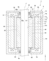
- FIG. 1 is a cross-sectional view taken along a central axis J of a rotating electric machine 1 according to this embodiment.
- the rotating electric machine 1 of this embodiment is a squirrel-cage three-phase AC motor.
- the rotating electric machine 1 of this embodiment is mounted on a vehicle using a rotating electric machine as a power source, such as a hybrid electric vehicle (HEV), a plug-in hybrid electric vehicle (PHV), or an electric vehicle (EV), and is used as the power source.
- the rotating electric machine 1 has both a function of outputting power as a motor and a function of generating electricity as a generator.
- the rotating electric machine 1 may be used as either a motor or a generator.
- the configuration of the rotating electric machine 1 is not limited to this embodiment, and may be, for example, a four- or more-phase AC motor.
- the rotating electric machine 1 of this embodiment has a rotor 20 configured as a cage rotor, a stator 10 that generates a rotating magnetic flux by an alternating current, and a housing 6 that accommodates the rotor 20 and the stator 10.
- a rotating force is generated in the rotor 20 by linking the rotating magnetic flux generated by the stator 10 with an induced current generated in the conductor portion 40 of the rotor 20 configured as a cage rotor.
- the housing 6 has a housing body 6a, a bearing holder 6b, and a pair of bearings 8a, 8b.
- the housing body 6a has a tubular portion 6d and a bottom plate portion 6e.
- the tubular portion 6d is cylindrical with its center on the central axis J.
- the bottom plate portion 6e extends radially inward from the end of the tubular portion 6d on the other axial side (-Z side).
- the bottom plate portion 6e holds the bearing 8a.
- the bearing holder 6b covers the opening on one axial side (+Z side) of the housing body 6a.
- the bearing holder 6b holds the bearing 8b.
- the stator 10 is fixed to the inner peripheral surface of the cylindrical portion 6d.
- the stator 10 is annular about the central axis J.
- the stator 10 surrounds the rotor 20 from the radial outside.
- the stator 10 has an annular stator core 11 and a coil 12 attached to the stator core 11.
- the stator core 11 is formed by stacking a plurality of electromagnetic steel sheets in the axial direction.
- the stator core 11 has a cylindrical core back portion 11a centered on the central axis J, and a plurality of stator teeth portions 11b that protrude radially inward from the inner peripheral surface of the core back portion 11a and are arranged in the circumferential direction.
- the coil 12 is attached to the stator teeth portion 11b.
- the coil 12 includes three-phase coils, U-phase, V-phase, and W-phase, in which the AC current flows through them in different phases.
- the rotor 20 rotates about the central axis J.
- the rotor 20 is rotatably supported by a pair of bearings 8a, 8b.
- the rotor 20 has a shaft 29, a rotor core 21, a plurality of conductor portions 40, a pair of end rings 50, and a pair of plate members 60.
- the shaft 29 is cylindrical and extends axially about the central axis J.
- the shaft 29 is supported by a pair of bearings 8a, 8b.
- the rotor core 21 extends in the axial direction, for example, with a uniform cross section.
- the rotor core 21 is substantially circular when viewed in the axial direction.
- the outer peripheral surface of the rotor core 21 faces the inner peripheral surface of the stator 10 in the radial direction with a gap therebetween.
- the rotor core 21 is constructed by stacking multiple electromagnetic steel plates in the axial direction.
- the rotor core 21 is fixed to the shaft 29.
- the rotor core 21 also holds multiple conductor portions 40 and a pair of end rings 50.
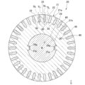
- FIG. 2 is a cross-sectional view perpendicular to the central axis J of the rotor 20.
- the rotor core 21 is provided with a central hole 21h penetrating in the axial direction and a plurality of slots 30.
- the central hole 21h is substantially circular and centered on the central axis J.
- a shaft 29 is inserted into the central hole 21h.
- An inner circumferential surface of the central hole 21h is provided with a pair of protrusions 21p protruding radially inward.
- an outer circumferential surface of the shaft 29 is provided with a pair of grooves 29g extending along the axial direction.
- the protrusions 21p are inserted into the grooves 29g.
- the rotor core 21 is positioned in the circumferential direction with respect to the shaft 29.
- the multiple slots 30 are arranged at equal intervals along the circumferential direction.
- the slots 30 extend in the axial direction with a uniform cross-sectional shape.
- the slots 30 extend radially and open at their radially outer ends to the outer peripheral surface 21a of the rotor core 21.
- the rotor core 21 also has teeth portions 22 provided between adjacent slots 30 in the circumferential direction.
- the slots 30 are located between adjacent teeth portions 22 in the circumferential direction.
- the multiple teeth portions 22 are arranged at equal intervals along the circumferential direction. The shapes of the slots 30 and the teeth portions 22 will be described in detail later.
- the conductor portion 40 is rod-shaped and disposed in the slot 30, extending along the axial direction.
- the conductor portion 40 is made of a non-magnetic and conductive material, such as an aluminum alloy.
- the conductor portion 40 is formed by die-casting into the slot 30. Therefore, the cross-sectional shape of the conductor portion 40 as viewed from the axial direction is approximately the same as the cross-sectional shape of the slot 30.
- the conductor portion 40 extends linearly along the axial direction of the rotor core 21.
- the conductor portion 40 may extend at a slight circumferential incline with respect to the axial direction.
- the length dimension of the conductor portion 40 is approximately equal to the axial dimension of the rotor core 21.
- the ends of the multiple conductor portions 40 on one axial side and the other axial side are each connected to an end ring 50.
- the multiple conductor portions 40 lined up in the circumferential direction are short-circuited with each other.
- An induced current flows in the conductor portion 40 due to the rotating magnetic flux generated by the stator 10 when the rotor 20 rotates.
- the induced current flows in the axial direction through the conductor portion 40.
- the end rings 50 are located on one axial side and the other axial side of the rotor core 21.
- the end rings 50 are annular about the central axis J.
- the end rings 50 face the outer peripheral surface of the shaft 29 in the radial direction with a gap therebetween.
- the end rings 50 connect the multiple conductor portions 40 together.
- the end rings 50 are made of a non-magnetic, conductive material such as an aluminum alloy. In this embodiment, the end rings 50 are formed integrally with the conductor portions 40 by die-cast molding.
- the plate members 60 are plate-shaped and extend along a plane perpendicular to the central axis J.
- the pair of plate members 60 are located between the end faces of the rotor core 21 on one axial side and the other axial side, respectively, and the end rings 50.
- the plate member 60 protects the rotor core 21 when the conductor portion 40 and the end rings 50 are molded.
- the rotor core 21 is composed of multiple electromagnetic steel plates.
- the conductor portion 40 and the end rings 50 are die-cast to embed a part of the rotor core 21. If the gap between the electromagnetic steel plates that make up the rotor core 21 becomes large, there is a risk that the molten metal that is the material for the conductor portion 40 and the end rings 50 will enter the gap. For this reason, the rotor core 21 is placed in a mold that molds the conductor portion 40 and the end rings 50 in a state where the electromagnetic steel plates are compressed in the axial direction to make them adhere to each other.
- the plate member 60 protects the axial end faces of the rotor core 21 when the rotor core 21 is compressed, and suppresses damage to the rotor core 21.
- the plate member 60 is preferably made of a metal material such as steel or an aluminum alloy to ensure sufficient strength and rigidity.
- the plate member 60 has a first surface 60a and a second surface 60b that face in opposite axial directions.
- the first surface 60a faces and contacts the end surface of the rotor core 21.
- the second surface 60b faces and contacts the end ring 50.
- the second surface 60b is embedded by the end ring 50 when the end ring 50 is molded.
- the second surface 60b is provided with a protrusion 61 that protrudes in the axial direction.
- the end ring 50 is molded following the protrusion 61. Therefore, the end ring 50 is provided with a housing portion 51 that houses the protrusion 61.
- FIG. 3 is a partially enlarged cross-sectional view of a part of FIG. 3, a virtual straight line passing through the center of the slot 30 and extending in the radial direction is defined as a slot center line SL.
- the center of the slot 30 means the center of the slot 30 in the circumferential direction.
- the slot 30 in this embodiment has a symmetrical shape with respect to the slot center line SL.
- the imaginary straight line that passes through the center of the teeth portion 22 and extends in the radial direction is the teeth center line TL.
- the center of the teeth portion 22 means the center of the teeth portion 22 in the circumferential direction.
- the slot 30 in this embodiment has a symmetrical shape with respect to the teeth center line TL.
- the slot 30 has an inner end 36, an inner narrowed portion 32, a boundary portion 31, an outer narrowed portion 33, and an open end 34.
- the inner end 36, the inner narrowed portion 32, the boundary portion 31, the outer narrowed portion 33, and the open end 34 are arranged in this order from the radially inner side to the radially outer side.
- the inner end 36 is located at the radially inner end of the slot 30.
- An inner end point 30a is provided on the inner surface of the inner end 36, which is located at the radially innermost position of the inner surface of the slot 30.
- the inner end point 30a is located on the slot centerline SL.
- the inner surface of the inner end 36 connects the inner end point 30a and the inner surface 32a of the inner narrowed portion 32 with a uniform radius of curvature.
- the inner surface of the inner end 36 connects smoothly to the inner surface 32a of the inner narrowed portion 32.
- the radially inner end of the inner narrowing portion 32 is connected to the inner end portion 36. Meanwhile, a boundary portion 31 is provided at the radially outer end of the inner narrowing portion 32.
- the circumferential width of the inner narrowing portion 32 narrows as it moves radially inward from the boundary portion 31. Therefore, the inner surface 32a of the inner narrowing portion 32 approaches the slot center line SL as it moves radially inward.
- the inner surface 32a of the inner narrowing portion 32 extends in a straight line when viewed in the axial direction.
- a boundary portion 31 is provided at the radially inner end of the outer narrowing portion 33.
- the radially outer end of the outer narrowing portion 33 is connected to the open end 34.
- the circumferential width of the outer narrowing portion 33 narrows as it moves radially outward from the boundary portion 31. Therefore, the inner surface 33a of the outer narrowing portion 33 approaches the slot centerline SL as it moves radially outward.
- the inner surface 33a of the outer narrowing portion 33 extends in a straight line when viewed in the axial direction.
- the boundary portion 31 is located at the boundary between the inner narrowing portion 32 and the outer narrowing portion 33.
- the boundary portion 31 may connect the inner narrowing portion 32 and the outer narrowing portion 33 with a uniform radius of curvature so as to smoothly connect them.
- the open end 34 is located at the radially outer end of the slot 30.
- the slot 30 opens radially outward at the open end 34.
- the open end 34 extends radially with the same circumferential width. Therefore, the inner surface of the open end 34 extends parallel to the slot centerline SL.
- the conductor portion 40 is formed by die casting into the slot 30, so that the cross-sectional shape of the conductor portion 40 is approximately the same as the cross-sectional shape of the slot 30. Therefore, the conductor portion 40 has multiple surfaces that are in contact with or face the inner surfaces of the inner end portion 36, inner narrowing portion 32, boundary portion 31, outer narrowing portion 33, and open end portion 34 of the slot 30 through a small gap.
- the slot 30 has an outer facing surface 43 that faces the inner surface 33a of the outer narrowing portion 33 and extends parallel to the inner surface.
- the slot 30 has a circumferential width that narrows toward the radially outward direction in the outer narrowing portion 33. Therefore, the normal vector of the inner surface of the outer narrowing portion 33 includes a vector component that faces radially inward.
- the inner surface 33a of the outer narrowing portion 33 comes into contact with the outer opposing surface 43 of the conductor portion 40 and can receive the centrifugal force applied to the conductor portion 40.
- the boundary portion 31 in this embodiment is located radially inward of the radial center CP of the slot 30. Therefore, the region of the slot 30 radially outward of the boundary portion 31 is wider than the region of the slot 30 radially inward of the boundary portion 31.
- the outer narrowing portion 33 can be secured radially larger than the inner narrowing portion 32. That is, the inner surface 33a of the outer narrowing portion 33 in the slot 30 can be secured wide, and the surface pressure applied to the inner surface 33a of the outer narrowing portion 33 can be suppressed from increasing.
- the slot 30 has an inner narrowing portion 32 radially inside the boundary portion 31, which makes it easier to ensure a wide width dimension of the teeth portion 22 compared to a case where the slot 30 does not have the inner narrowing portion 32.
- the slot 30 has an inner narrowing portion 32, which makes it easier to ensure the circumferential width of the teeth portion 22, making it possible to increase the rotational torque of the rotor 20.
- the radial length dimension L1 of the outer narrowing portion 33 is greater than the radial length dimension L2 of the inner narrowing portion 32.
- the inner surface 33a of the outer narrowing portion 33 can be ensured to be wider than the inner surface of the inner narrowing portion 32.
- the radial length dimension L1 of the outer narrowing portion 33 is 1.5 times or more the radial length dimension L2 of the inner narrowing portion (L1 ⁇ 1.5 x L2).
- the dimensions of the outer narrowing portion 33 and the inner narrowing portion 32 are in the above-mentioned relationship, it is easy to ensure that the inner surface 33a of the outer narrowing portion 33 is sufficiently wide, and deformation of the rotor core 21 can be more reliably suppressed.
- the inclination angle ⁇ of the inner surface 33a of the outer narrowing portion 33 with respect to the slot center line SL is 20° or less.
- the inclination angle ⁇ is 10° or less over the entire inner surface 33a of the outer narrowing portion 33.
- the inner surface 33a of the outer narrowing portion 33 extends linearly when viewed in the axial direction.
- the inner surface 33a of the outer narrowing portion 33 may be a concavely curved surface or a convexly curved surface.
- the centrifugal force applied to the conductor portion 40 can be received by the entire inner surface 33a with uniform surface pressure, making it easier to suppress stress concentration on the rotor core 21.
- the inner surface 32a of the inner narrowing portion 32 extends linearly when viewed in the axial direction.
- the inner surface 32a of the inner narrowing portion 32 may be a concavely curved surface or a convexly curved surface.
- the inner surface 32a of the inner narrowing portion 32 linear, it becomes easier to ensure a wider cross-sectional area of the slot 30 compared to when the inner surface 32a is curved convexly. This makes it possible to increase the cross-sectional area of the conductor portion 40 arranged in the slot 30, and the electrical resistance of the conductor portion 40 can be reduced.
- the inner surface 32a on one circumferential side of the inner narrowed portion 32 extends parallel to the teeth center line TL of the teeth portion 22 located on one circumferential side of this inner surface 32a.
- the inner surface 32a on the other circumferential side of the inner narrowed portion 32 extends parallel to the teeth center line TL of the teeth portion 22 located on the other circumferential side of this inner surface 32a.
- the inner surface 32a of the inner narrowed portion 32 also functions as an outer surface facing the circumferential direction of the base end 22a of the teeth portion 22.
- the base end 22a of the teeth portion 22 means the radially inner end of the teeth portion 22.
- the outer surface of the base end 22a of the teeth portion 22 can be made parallel to the teeth center line TL. This allows the circumferential width of the base end 22a of the teeth portion 22 to be uniform along the radial direction, making it easier to form a magnetic path in the teeth portion 22 that is parallel to the teeth center line TL. This allows the magnetic flux density of the teeth portion 22 to be increased when the rotor 20 rotates, and the rotational torque of the rotor 20 to be increased.
- the slot 30 of this embodiment has an open end 34 at the radially outer end.
- the open end 34 extends radially with the same circumferential width.
- the circumferential width of the outer end 41 of the slot 30 arranged inside the open end 34 can be secured large.
- a large current can be passed through the conductor portion 40, and the rotational torque of the rotating electric machine 1 can be increased.
- the electrical resistance of the conductor portion 40 can be reduced, and the driving efficiency of the rotating electric machine 1 can be increased.
- the slot 30 of this embodiment has a shape that is symmetrical with respect to the slot center line SL. That is, the outer narrowing portion 33 of this embodiment has a shape that is symmetrical with respect to the slot center line SL.
- the centrifugal force applied to the conductor portion 40 can be received in a balanced manner by the inner surface 33a of the outer narrowing portion 33 located on one and the other circumferential sides of the slot center line SL.
- no part of the inner surface 33a of the outer narrowing portion 33 where the surface pressure is locally increased is generated, and deformation of the rotor core 21 caused by the centrifugal force can be suppressed.
- the teeth 22 located between the slots 30 also have a symmetrical shape with respect to the teeth center line TL. This makes it possible to form a stable magnetic path in the teeth 22 regardless of the direction in which the rotor 20 rotates, and makes it possible to stabilize the rotation of the rotor 20.
- rotors of modified examples that can be used in the rotating electric machine 1 of the above-described embodiment.
- the same components as those in the already-described embodiment or modified example are given the same reference numerals, and the description thereof is omitted.
- the rotors of each modified example differ from the above-described embodiment in the shape of the slots and the shape of the conductors accommodated in the slots.
- (Variation 1) 4 is a partially enlarged cross-sectional view of a rotor 120 of Modification 1.
- the rotor 120 has a rotor core 121 in which a plurality of slots 130 are provided, and a plurality of conductor portions 140 arranged in each of the slots 130.
- teeth portions 122 are provided between the slots 130 adjacent to each other in the circumferential direction.
- the slots 130 have an inner end portion 136, an inner narrowed portion 132, a boundary portion 131, an outer narrowed portion 133, and an open end portion 134.
- the inner surface 132a on one circumferential side of the inner narrowing portion 132 extends in a direction away from the tooth center line TL of the tooth portion 122 located on one circumferential side of the inner surface 132a as it moves radially inward.
- the inner surface 132a on the other circumferential side of the inner narrowing portion 132 extends in a direction away from the tooth center line TL of the tooth portion 122 located on the other circumferential side of the inner surface 132a as it moves radially inward.
- the circumferential width of the base end portion 122a of the tooth portion 122 can be made large, making it easier for magnetic flux to flow through the tooth portion 122.
- (Variation 2) 5 is a partially enlarged cross-sectional view of a rotor 220 of modified example 1.
- the rotor 220 has a rotor core 221 in which a plurality of slots 230 are provided, and a plurality of conductor portions 240 arranged in each of the slots 230.
- teeth portions 222 are provided between the slots 230 adjacent to each other in the circumferential direction.
- the slots 230 have an inner end portion 236, an inner narrowed portion 232, a boundary portion 231, an outer narrowed portion 233, and an open end portion 234.
- the slots 230 of this modified example have an expansion portion 235 located between the outer narrowed portion 233 and the open end portion 234.
- the expansion section 235 is located radially outward of the outer narrowing section 233 and radially inward of the open end 234.
- the expansion section 235 extends circumferentially on both sides of the outer narrowing section 233 and the open end 234.
- a part of the conductor section 240 is disposed inside the expansion section 235.
- the part of the conductor section 240 that is disposed inside the expansion section 235 is called the conductor expansion section 245.
- the conductor expansion section 245 is disposed inside the expansion section 235 of the slot 230, so that the radially outward movement of the conductor section 240 caused by centrifugal force can be more reliably suppressed.
- the centrifugal force applied to the conductor section 240 is received by both the inner surface of the outer narrowing section 233 and the inner surface of the expansion section 235. According to this modified example, stress caused by receiving the centrifugal force is less likely to concentrate on the inner surface of the outer narrowing section 233 and the inner surface of the expansion section 235, respectively, and deformation of the rotor core 221 can be suppressed.
- the conductor extension portion 245 can be arranged close to the outer peripheral surface of the rotor core 221.
- the induced current flowing through the conductor portion 240 has a high current density in the region close to the outer peripheral surface of the rotor core 221 due to the skin effect.
- the conductor extension portion 245 can be brought closer to the outer peripheral surface of the rotor core 221, making it possible to pass more current through the conductor portion 240 and increasing the rotational torque of the rotating electric machine 1.
- the electrical resistance of the conductor portion 240 can also be reduced, thereby improving the driving efficiency of the rotating electric machine 1.
- the rotor may be manufactured by inserting a preformed rod-shaped conductor into a slot in a rotor core and connecting end rings to both ends of the conductor.
- the cross-sectional shape of the slot can be configured as described above to prevent the conductor from coming off the slot.
- the material of the conductor and end rings is not limited to aluminum alloy, but may be copper or a copper-based alloy, etc.
- the present technology can be configured as follows: (1) A rotor for a rotating electric machine that rotates about a central axis, the rotor core having a plurality of slots arranged in the circumferential direction and penetrating in the axial direction, a plurality of conductor parts arranged in the slots, and a pair of end rings located on one axial side and the other axial side of the rotor core, respectively, connecting the plurality of conductor parts, the slots extending in the radial direction and opening at radially outer ends on the outer circumferential surface of the rotor core, the slots having a boundary portion located radially inside the midpoint of the radial length dimension, an inner narrowed portion whose circumferential width narrows from the boundary portion toward the radially inner side, and an outer narrowed portion whose circumferential width narrows from the boundary portion toward the radially outer side.
- a rotating electric machine comprising the rotor according to any one of (1) to (7) and a stator surrounding the rotor from the radially outer side, the stator having an annular stator core and a coil attached to the stator core.
Landscapes
- Engineering & Computer Science (AREA)
- Power Engineering (AREA)
- Iron Core Of Rotating Electric Machines (AREA)
Abstract
本発明のロータの一つの態様は、中心軸線を中心として回転可能なロータであって、ロータコアと、ロータコアと軸方向に対向する第1プレート面および第1プレート面とは逆側を向く第2プレート面を有するエンドプレートと、を備える。第1プレート面は、エンドプレートの少なくとも一部が軸方向に弾性変形した状態でロータコアに軸方向に接触する接触面を有する。接触面は、第1面を有する。エンドプレートが弾性変形していない状態において第1面は、径方向外側に向かうに従って、軸方向のうちエンドプレートに対してロータコアが配置される第1側に位置する。エンドプレートが弾性変形していない状態において第1面の径方向外側の端部は、接触面のうち最も第1側に位置する部分である。エンドプレートは、エンドプレートの外面に設けられた第1凹部を有する。第1凹部の少なくとも一部は、第1面と軸方向に重なっている。
Description
本発明は、ロータおよび回転電機に関する。
従来から、ロータコアのスロット内に導体部が配置されるカゴ型ロータが知られている。カゴ型ロータでは、導体部がスロットから離脱することを抑制する構造が必要となる。日本国公開公報:特開2016-171627号公報には、ロータコアに形成された各スロットの内側面に周方向に突出する凸部を設け、当該凸部によって導体部に付与される遠心力を受ける構造が開示されている。
近年、自動車の駆動源としてカゴ型ロータを用いた回転電機を採用する場合がある。このような回転電機には、小型化、高出力化が求められており、必然的に高速回転が要求される傾向にある。従来構造のロータを高速回転させると、導体部に付与される大きな遠心力によりロータコアに局所的に大きな力が付与されてロータコアに変形が生じ、導電部がスロットから離脱するおそれがある。
本発明は、上記事情に鑑みて、ロータコアの変形を抑制しつつ遠心力に起因する導電部のスロットからの離脱を抑制できるロータ、および回転電機の提供を目的の一つとする。
本発明のロータの一つの態様は、中心軸線を中心として回転する回転電機のロータであって、周方向に並び軸方向に貫通する複数のスロットが設けられるロータコアと、前記スロット内に配置される複数の導体部と、前記ロータコアの軸方向一方側、および他方側にそれぞれ位置し複数の前記導体部同士を繋ぐ一対のエンドリングと、を備える。前記スロットは、径方向に延びて径方向外側の端部において前記ロータコアの外周面に開口する。前記スロットは、径方向の長さ寸法の中点よりも径方向内側に位置する境界部と、前記境界部から径方向内側に向かうに従い周方向幅が狭まる内側狭窄部と、前記境界部から径方向外側に向かうに従い周方向幅が狭まる外側狭窄部と、を有する。
本発明の回転電機の一つの態様は、上述のロータと、前記ロータを径方向外側から囲むステータと、を有する。前記ステータは、円環状のステータコアと前記ステータコアに装着されるコイルとを有する。
本発明の一つの態様によれば、ロータコアの変形を抑制しつつ遠心力に起因する導電部のスロットからの離脱を抑制できるロータ、および回転電機を提供できる。
以下、本発明に係るロータ20および当該ロータ20を有する回転電機1について、図面を参照しつつ詳細に説明する。各図には、必要に応じてZ軸を図示する。Z軸は、回転電機1の中心軸線Jに平行な方向である。また、以下の説明において、回転電機1の中心軸線Jと平行な方向を単に「軸方向」と呼び、中心軸線Jを中心とする径方向を単に「径方向」と呼び、中心軸線Jを中心とする周方向、すなわち、中心軸線Jの軸周りを単に「周方向」と呼ぶ。
図1は、本実施形態の回転電機1の中心軸線Jに沿う断面図である。
本実施形態の回転電機1は、カゴ型三相交流モータである。本実施形態の回転電機1は、ハイブリッド自動車(HEV)、プラグインハイブリッド自動車(PHV)、例えば、電気自動車(EV)等、回転電機を動力源とする車両に搭載され、その動力源として使用される。回転電機1は、発動機として動力を出力する機能と発電機として発電する機能とを兼ね備えている。また、回転電機1は、発動機、又は発電機の何れかとして用いられるものであってもよい。また、回転電機1の構成は本実施形態に限定されず、例えば四相以上の交流モータであってもよい。
本実施形態の回転電機1は、カゴ型三相交流モータである。本実施形態の回転電機1は、ハイブリッド自動車(HEV)、プラグインハイブリッド自動車(PHV)、例えば、電気自動車(EV)等、回転電機を動力源とする車両に搭載され、その動力源として使用される。回転電機1は、発動機として動力を出力する機能と発電機として発電する機能とを兼ね備えている。また、回転電機1は、発動機、又は発電機の何れかとして用いられるものであってもよい。また、回転電機1の構成は本実施形態に限定されず、例えば四相以上の交流モータであってもよい。
本実施形態の回転電機1は、カゴ型ロータとして構成されるロータ20と、交流電流によって回転磁束を発生させるステータ10と、ロータ20およびステータ10を収容するハウジング6と、を有する。回転電機1において、ステータ10から発生する回転磁束と、カゴ型ロータとして構成されたロータ20の導体部40に発生する誘導電流とが鎖交することにより、ロータ20に回転力が発生する。
ハウジング6は、ハウジング本体6aとベアリングホルダ6bと、一対のベアリング8a、8bと、を有する。ハウジング本体6aは、筒部6dと底板部6eとを有する。筒部6dは、中心軸線Jを中心とする円筒状である。底板部6eは、筒部6dの軸方向他方側(-Z側)の端部から径方向内側に延びる。底板部6eは、ベアリング8aを保持する。ベアリングホルダ6bは、ハウジング本体6aの軸方向一方側(+Z側)の開口を覆う。ベアリングホルダ6bは、ベアリング8bを保持する。
ステータ10は、筒部6dの内周面に固定される。ステータ10は、中心軸線Jを中心とする円環状である。ステータ10は、ロータ20を径方向外側から囲む。ステータ10は、円環状のステータコア11と、ステータコア11に装着されるコイル12と、を有する。ステータコア11は、複数の電磁鋼板を軸方向に積層することで構成される。ステータコア11は、中心軸線Jを中心とする円筒状のコアバック部11aと、コアバック部11aの内周面から径方向内側に突出するとともに周方向に並ぶ複数のステータティース部11bと、を有する。コイル12は、ステータティース部11bに装着される。コイル12は、流れる交流電流の位相が異なるU相、V相、及びW相の三相のコイルを含む。
ロータ20は、中心軸線Jを中心として回転する。ロータ20は、一対のベアリング8a、8bに回転可能に支持される。ロータ20は、シャフト29と、ロータコア21と、複数の導体部40と、一対のエンドリング50と、一対のプレート部材60と、を有する。シャフト29は、中心軸線Jを中心として軸方向に延びる円柱状である。シャフト29は、一対のベアリング8a、8bによって支持される。
ロータコア21は、例えば一様な断面で軸方向に延びる。ロータコア21は、軸方向から見て略円形である。ロータコア21の外周面は、ステータ10の内周面と隙間を介して径方向に対向する。ロータコア21は、複数の電磁鋼板を軸方向に積層することで構成される。ロータコア21は、シャフト29に固定される。また、ロータコア21は、複数の導体部40および一対のエンドリング50を保持する。
図2は、ロータ20の中心軸線Jと直交する断面図である。
図2に示すように、ロータコア21には、軸方向に貫通する中央孔21hおよび複数のスロット30が設けられる。中央孔21hは、中心軸線Jを中心とする略円形である。中央孔21hには、シャフト29が挿入される。中央孔21hの内周面には、径方向内側に突出する一対の突起部21pが設けられる。一方で、シャフト29の外周面には、軸方向に沿って延びる一対の溝部29gが設けられる。突起部21pは、溝部29gに挿入される。これらにより、ロータコア21は、シャフト29に対して周方向に位置決めされる。
図2に示すように、ロータコア21には、軸方向に貫通する中央孔21hおよび複数のスロット30が設けられる。中央孔21hは、中心軸線Jを中心とする略円形である。中央孔21hには、シャフト29が挿入される。中央孔21hの内周面には、径方向内側に突出する一対の突起部21pが設けられる。一方で、シャフト29の外周面には、軸方向に沿って延びる一対の溝部29gが設けられる。突起部21pは、溝部29gに挿入される。これらにより、ロータコア21は、シャフト29に対して周方向に位置決めされる。
複数のスロット30は、周方向に沿って等間隔に並ぶ。スロット30は、一様な断面形状で軸方向に延びる。スロット30は、径方向に延びて径方向外側の端部においてロータコア21の外周面21aに開口する。また、ロータコア21は、周方向に隣り合うスロット30の間に設けられるティース部22を有する。すなわち、スロット30は、周方向に隣り合うティース部22同士の間に位置する。複数のティース部22は、周方向に沿って等間隔に並ぶ。スロット30およびティース部22の形状については、後段において詳細に説明する。
導体部40は、スロット30に配置され軸方向に沿って延びる棒状である。導体部40は、例えば、アルミニウム合金などの非磁性体かつ導電性の材料によって構成される。導体部40は、スロット30内にダイキャストすることで形成される。したがって、軸方向から見た導体部40の断面形状は、スロット30の断面形状と略等しい。
図1に示すように、導体部40は、ロータコア21の軸方向に沿って直線状に延びる。なお、導体部40は、軸方向に対し周方向に若干傾斜して延びていてもよい。また、導体部40の長さ寸法は、ロータコア21の軸方向寸法と略等しい。複数の導体部40の軸方向一方側、および他方側の端部は、それぞれエンドリング50に接続される。これにより、周方向にならぶ複数の導体部40は、互いに短絡されている。導体部40には、ロータ20の回転時にステータ10によって生じる回転磁束によって、誘導電流が流れる。誘導電流は、導体部40を軸方向に流れる。
エンドリング50は、ロータコア21の軸方向一方側、および他方側にそれぞれ位置する。エンドリング50は、中心軸線Jを中心とする円環状である。エンドリング50は、シャフト29の外周面と隙間を空けて径方向に対向する。エンドリング50は、複数の導体部40同士を繋ぐ。エンドリング50は、導体部40と同様に、例えば、アルミニウム合金などの非磁性体かつ導電性の材料によって構成される。本実施形態において、エンドリング50は、導体部40と一体的にダイカスト成形されて形成される。
プレート部材60は、中心軸線Jと直交する平面に沿って延びる板状である。一対のプレート部材60は、ロータコア21の軸方向一方側、および他方側の端面とエンドリング50との間にそれぞれ位置する。
プレート部材60は、導体部40およびエンドリング50の成型時に、ロータコア21を保護する。上述したように、ロータコア21は、複数の電磁鋼板から構成される。また、導体部40およびエンドリング50は、ロータコア21の一部を埋め込むようにダイカスト成形される。ロータコア21を構成する電磁鋼板の間の隙間が大きくなると、この隙間に導体部40およびエンドリング50の素材となる溶融金属が侵入してしまう虞がある。このため、ロータコア21は、軸方向に圧縮されて電磁鋼板同士を密着させた状態で、導体部40およびエンドリング50を成形する金型内に配置される。プレート部材60は、ロータコア21を圧縮する際に、ロータコア21の軸方向端面を保護しロータコア21に損傷が生じることを抑制する。プレート部材60は、十分な強度および剛性を確保するために、鉄鋼又はアルミニウム合金等の金属材料から構成することが好ましい。
プレート部材60は、互いに軸方向の反対側を向く第1面60aおよび第2面60bを有する。第1面60aは、ロータコア21の端面と対向し接触する。第2面60bは、エンドリング50と対向し接触する。第2面60bは、エンドリング50の成型時にエンドリング50によって埋め込まれる。第2面60bには、軸方向に突出する凸部61が設けられる。一方で、エンドリング50は、凸部61に倣って成形される。このため、エンドリング50には、凸部61を収容する収容部51が設けられる。ロータ20が中心軸線J周りに回転すると、エンドリング50および導体部40には、遠心力が加わる。本実施形態によれば、凸部61が収容部51の内側面に引っ掛かることでエンドリング50および導体部40の径方向への移動を抑制できる。
図3は、図2の一部を拡大した部分拡大断面図である。
図3に示すように、スロット30の中心を通って径方向に延びる仮想的な直線をスロット中心線SLとする。ここでの「スロット30の中心」とは、周方向におけるスロット30の中心を意味する。本実施形態のスロット30は、スロット中心線SLに対し対称な形状を有する。
図3に示すように、スロット30の中心を通って径方向に延びる仮想的な直線をスロット中心線SLとする。ここでの「スロット30の中心」とは、周方向におけるスロット30の中心を意味する。本実施形態のスロット30は、スロット中心線SLに対し対称な形状を有する。
また、ティース部22の中心を通って径方向に延びる仮想的な直線をティース中心線TLとする。ここでの「ティース部22の中心」とは、周方向におけるティース部22の中心を意味する。本実施形態のスロット30は、ティース中心線TLに対し対称な形状を有する。
スロット30は、内側端部36と、内側狭窄部32と、境界部31と、外側狭窄部33と、開口端部34と、を有する。内側端部36、内側狭窄部32、境界部31、外側狭窄部33、および開口端部34は、径方向内側から径方向外側に向かってこの順で並ぶ。
内側端部36は、スロット30の径方向内側の端部に位置する。内側端部36の内側面には、スロット30の内側面のうち最も径方向内側に位置する内端点30aが設けられる。内端点30aは、スロット中心線SL上に配置される。内側端部36の内側面は、一様な曲率半径で内端点30aと内側狭窄部32の内側面32aとを繋ぐ。内側端部36の内側面は、内側狭窄部32の内側面32aに滑らかに繋がる。
内側狭窄部32の径方向内側の端部は、内側端部36に繋がる。一方で、内側狭窄部32の径方向外側の端部には、境界部31が設けられる。内側狭窄部32は、境界部31から径方向内側に向かうに従い周方向幅が狭まる。したがって、内側狭窄部32の内側面32aは、径方向内側に向かうに従いスロット中心線SLに近づく。内側狭窄部32の内側面32aは、軸方向から見て直線状に延びる。
外側狭窄部33の径方向内側の端部には、境界部31が設けられる。外側狭窄部33の径方向外側の端部は、開口端部34に繋がる。外側狭窄部33は、境界部31から径方向外側に向かうに従い周方向幅が狭まる。したがって、外側狭窄部33の内側面33aは、径方向外側に向かうに従いスロット中心線SLに近づく。外側狭窄部33の内側面33aは、軸方向から見て直線状に延びる。
境界部31は、内側狭窄部32と外側狭窄部33との境界部分に位置する。境界部31は、内側狭窄部32と外側狭窄部33とを滑らかに繋ぐように一様な曲率半径で繋いでいてもよい。
開口端部34は、スロット30の径方向外側の端部に位置する。スロット30は、開口端部34において径方向外側に開口する。開口端部34は、同一な周方向幅で径方向に延びる。したがって、開口端部34の内側面は、スロット中心線SLと平行に延びる。
上述したように、導体部40は、スロット30内にダイカストすることで成形されるため、導体部40の断面形状はスロット30の断面形状とほぼ等しくなる。このため、導体部40は、スロット30の内側端部36、内側狭窄部32、境界部31、外側狭窄部33、および開口端部34の内側面にそれぞれ接触、またはわずかな隙間を介して対向する複数の面を有する。特に、スロット30は、外側狭窄部33の内側面33aと対向し、当該内側面と平行に延びる外側対向面43を有する。
本実施形態のスロット30は、外側狭窄部33において径方向外側に向かうに従い周方向幅が狭まる。このため、外側狭窄部33の内側面の法線ベクトルは、径方向内側を向くベクトル成分を含んでいる。導体部40に遠心力が付与された場合に、外側狭窄部33の内側面33aは、導体部40の外側対向面43と接触し導体部40に付与される遠心力を受けることができる。
図3に示すように、本実施形態の境界部31は、スロット30の径方向の長さ方向中心CPよりも径方向内側に位置する。このため、スロット30は、境界部31よりも径方向外側の領域が、境界部31よりも径方向内側の領域よりも広くなる。本実施形態によれば、外側狭窄部33を内側狭窄部32よりも径方向に大きく確保することができる。すなわち、スロット30において外側狭窄部33の内側面33aを広く確保することができ、外側狭窄部33の内側面33aに加わる面圧が高まることを抑制できる。本実施形態によれば、スロット30の内側面に、ロータ20の高速回転に伴い導体部40の大きな遠心力が付与されても、局所的に大きな力が加わることを抑制することができ、ロータコア21の変形を抑制できる。これにより、遠心力に起因する導体部40のスロット30からの離脱を抑制できる。
また、本実施形態によれば、スロット30が境界部31の径方向内側に内側狭窄部32を有することで、内側狭窄部32を有さない場合と比較して、ティース部22の幅寸法を広く確保しやすくなる。ロータコア21の回転時には、導体部40に流れる誘導電流などによってティース部22には径方向に向かう磁束が生じて、ロータ20にトルクを生じさせる。ティース部22の幅寸法が局所的に狭まる部分があると、ティース部22に磁気飽和が生じるなどしてティース部22に磁束が流れ難くなる。本実施形態によれば、スロット30が内側狭窄部32を有することでティース部22の周方向幅を確保しやすくなり、ロータ20の回転トルクを高めることが可能となる。
本実施形態において、外側狭窄部33の径方向の長さ寸法L1は、内側狭窄部32の径方向の長さ寸法L2よりも大きい。本実施形態によれば、外側狭窄部33の内側面33aを内側狭窄部32の内側面よりも広く確保することができる。これにより、外側狭窄部33で導体部40の遠心力を受ける場合に、外側狭窄部33の内側面33aの面圧が高まることを抑制することができ、遠心力に起因するロータコア21の変形を抑制し、導体部40のスロット30からの離脱を抑制できる。
また、外側狭窄部33の径方向の長さ寸法L1は、内側狭窄部の径方向の長さ寸法L2に対して、1.5倍以上であることが好ましい(L1≧1.5×L2)。外側狭窄部33および内側狭窄部32の寸法を上述の関係とする場合、外側狭窄部33の内側面33aを十分に広く確保しやすく、ロータコア21の変形をより確実に抑制できる。
本実施形態において、外側狭窄部33の内側面33aは、スロット中心線SLに対する傾斜角θが20°以下であることが好ましい。傾斜角θを20°以下とすることで、導体部40のから内側面33aの各部に付与される面圧を低減することができる。なお、外側狭窄部33の内側面33aが湾曲する場合において、外側狭窄部33の内側面33aの全体に亘って傾斜角θが10°以下となっていることが好ましい。
本実施形態の外側狭窄部33の内側面33aは、軸方向から見て直線状に延びる。なお、外側狭窄部33の内側面33aは、凹状に湾曲する曲面であっても、凸状に湾曲する曲面であってもよい。しかしながら、外側狭窄部33の内側面33aを直線状とすることで、導体部40に付与される遠心力を内側面33a全体に均一な面圧で受けることができ、ロータコア21への応力集中を抑制しやすくなる。
本実施形態の内側狭窄部32の内側面32aは、軸方向から見て直線状に延びる。なお、内側狭窄部32の内側面32aは、凹状に湾曲する曲面であっても、凸状に湾曲する曲面であってもよい。しかしながら、内側狭窄部32の内側面32aを直線状とすることで、内側面32aが凹状に湾曲する場合と比較してティース部22の周方向幅を広く確保しやすくなる。これにより、ティース部22に磁束が流れやすくすることができ、ロータ20の回転トルクを高めることができる。さらに、内側狭窄部32の内側面32aを直線状とすることで、内側面32aが凸状に湾曲する場合と比較して、スロット30の断面積を広く確保しやすくなる。これにより、スロット30に配置する導体部40の断面積も大きくすることができ、導体部40の電気抵抗を低減することができる。
軸方向から見て、内側狭窄部32の周方向一方側の内側面32aは、この内側面32aに対し周方向一方側に位置するティース部22のティース中心線TLと平行に延びる。同様に、内側狭窄部32の周方向他方側の内側面32aは、この内側面32aに対し周方向他方側に位置するティース部22のティース中心線TLと平行に延びる。
内側狭窄部32の内側面32aは、ティース部22の基端部22aの周方向を向く外側面としても機能する。なお、ここで、ティース部22の基端部22aとは、ティース部22の径方向内側の端部を意味する。本実施形態によれば、ティース部22の基端部22aの外側面をティース中心線TLと平行とすることができる。これにより、ティース部22の基端部22aの周方向幅を径方向に沿って一様とすることができ、ティース部22にティース中心線TLに平行な磁路を形成させやすい。これにより、ロータ20回転時のティース部22の磁束密度を高めることができ、ロータ20の回転トルクを高めることができる。
本実施形態のスロット30は、径方向外側の端部に開口端部34を有する。また、開口端部34は、同一な周方向幅で径方向に延びる。本実施形態によれば、開口端部34の内側に配置されるスロット30の外側端部41の周方向幅を大きく確保することができる。上述したように、ロータ20の回転時に、導体部40には、ステータ10から受ける回転磁束の影響で軸方向に沿って誘導電流が流れる。導体部40を流れる誘導電流は、表皮効果によってロータ20の外周面21aに近い外側端部41において電流密度が最も高くなる。本実施形態によれば、導体部40の外側端部41の周方向幅を大きく確保することで、導体部40に多くの電流を流すことができ、回転電機1の回転トルクを高めることができる。また、導体部40の電気抵抗を低減することもでき、回転電機1の駆動効率を高めることができる。
本実施形態のスロット30は、スロット中心線SLに対し対称な形状を有する。すなわち、本実施形態の外側狭窄部33は、スロット中心線SLに対し対称な形状を有する。本実施形態によれば、導体部40に付与される遠心力をスロット中心線SLに対し周方向一方側および他方側に位置する外側狭窄部33の内側面33aによってバランスよく受けることができる。結果的に外側狭窄部33に内側面33aに局所的に面圧が高まる部分を生じさせることがなく、遠心力に起因するロータコア21の変形を抑制できる。
また、本実施形態によれば、スロット30を対称形状とすることで、スロット30の間に位置するティース部22もティース中心線TLに対し対称な形状となる。これにより、ロータ20が何れの方向に回転する場合においても、ティース部22に安定的な磁路を形成することが可能となり、ロータ20の回転を安定させることができる。
<変形例>
以下に、上述の実施形態の回転電機1に採用可能な、変形例のロータについて説明する。以下に説明する各変形例の説明において、すでに説明した実施形態、又は変形例と同一の構成要素については、同一符号を付しその説明を省略する。各変形例のロータは、上述の実施形態と比較して、スロットの形状および当該スロットに収容される導体部の形状が異なる。
以下に、上述の実施形態の回転電機1に採用可能な、変形例のロータについて説明する。以下に説明する各変形例の説明において、すでに説明した実施形態、又は変形例と同一の構成要素については、同一符号を付しその説明を省略する。各変形例のロータは、上述の実施形態と比較して、スロットの形状および当該スロットに収容される導体部の形状が異なる。
(変形例1)
図4は、変形例1のロータ120の部分拡大断面図である。上述の実施形態と同様に、ロータ120は、複数のスロット130が設けられるロータコア121と、それぞれスロット130に配置される複数の導体部140と、を有する。また、ロータコア121において、周方向に隣り合うスロット130同士の間にはティース部122が設けられる。スロット130は、内側端部136、内側狭窄部132、境界部131、外側狭窄部133、および開口端部134を有する。
図4は、変形例1のロータ120の部分拡大断面図である。上述の実施形態と同様に、ロータ120は、複数のスロット130が設けられるロータコア121と、それぞれスロット130に配置される複数の導体部140と、を有する。また、ロータコア121において、周方向に隣り合うスロット130同士の間にはティース部122が設けられる。スロット130は、内側端部136、内側狭窄部132、境界部131、外側狭窄部133、および開口端部134を有する。
本変形例において、内側狭窄部132の周方向一方側の内側面132aは、この内側面132aに対し周方向一方側に位置するティース部122のティース中心線TLに対し径方向内側に向かうに従い離れる方向に延びる。同様に、内側狭窄部132の周方向他方側の内側面132aは、この内側面132aに対し周方向他方側に位置するティース部122のティース中心線TLに対し径方向内側に向かうに従い離れる方向に延びる。本変形例によれば、ティース部122の基端部122aの周方向幅を大きく確保して、ティース部122に磁束を流れ易くすることができる。
(変形例2)
図5は、変形例1のロータ220の部分拡大断面図である。上述の実施形態と同様に、ロータ220は、複数のスロット230が設けられるロータコア221と、それぞれスロット230に配置される複数の導体部240と、を有する。また、ロータコア221において、周方向に隣り合うスロット230同士の間にはティース部222が設けられる。スロット230は、内側端部236、内側狭窄部232、境界部231、外側狭窄部233、および開口端部234を有する。さらに、本変形例のスロット230は、外側狭窄部233と開口端部234との間に位置する拡張部235を有する。
図5は、変形例1のロータ220の部分拡大断面図である。上述の実施形態と同様に、ロータ220は、複数のスロット230が設けられるロータコア221と、それぞれスロット230に配置される複数の導体部240と、を有する。また、ロータコア221において、周方向に隣り合うスロット230同士の間にはティース部222が設けられる。スロット230は、内側端部236、内側狭窄部232、境界部231、外側狭窄部233、および開口端部234を有する。さらに、本変形例のスロット230は、外側狭窄部233と開口端部234との間に位置する拡張部235を有する。
拡張部235は、外側狭窄部233の径方向外側、かつ開口端部234の径方向内側に位置する。拡張部235は、外側狭窄部233および開口端部234に対し周方向両側に広がる。拡張部235の内部には、導体部240の一部が配置される。導体部240において、拡張部235の内部に配置される部分を導体拡張部245と呼ぶ。
本変形例によれば、導体拡張部245が、スロット230の拡張部235の内部に配置されることで、遠心力に起因する導体部240の径方向外側への移動をより確実に抑制できる。なお、本変形例において、導体部240に付与される遠心力は、外側狭窄部233の内側面と拡張部235の内側面の両方で受けられる。本変形例によれば、外側狭窄部233の内側面と拡張部235の内側面において、それぞれ遠心力を受けるための応力が集中しにくく、ロータコア221の変形を抑制できる。
本変形例によれば、拡張部235を外側狭窄部233と開口端部234との間に配置することで、導体拡張部245をロータコア221の外周面の近くに配置できる。導体部240を流れる誘導電流は、表皮効果によってロータコア221の外周面に近い領域で電流密度が高くなる。本実施形態によれば、導体拡張部245をロータコア221の外周面に近づけることができ、導体部240に多くの電流を流すことが可能となり、回転電機1の回転トルクを高めることができる。また、本変形例によれば、導体部240の電気抵抗を低減することもでき、回転電機1の駆動効率を高めることができる。
以上に、本発明の実施形態を説明したが、実施形態における各構成およびそれらの組み合わせ等は一例であり、本発明の趣旨から逸脱しない範囲内で、構成の付加、省略、置換およびその他の変更が可能である。また、本発明は実施形態によって限定されることはない。
例えば、ロータは、予め成形した棒状の導体部を、ロータコアのスロットに挿入し、導体部の両端部にエンドリングを接続することで製造してもよい。この場合においても、スロットの断面形状を上述の構成とすることで、導体部のスロットからの離脱を抑制できる。また、導体部、およびエンドリングの材質は、アルミニウム合金に限らず、銅又は銅系合金等であってもよい。
なお、本技術は以下のような構成をとることが可能である。(1) 中心軸線を中心として回転する回転電機のロータであって、周方向に並び軸方向に貫通する複数のスロットが設けられるロータコアと、前記スロット内に配置される複数の導体部と、前記ロータコアの軸方向一方側、および他方側にそれぞれ位置し複数の前記導体部同士を繋ぐ一対のエンドリングと、を備え、前記スロットは、径方向に延びて径方向外側の端部において前記ロータコアの外周面に開口し、前記スロットは、径方向の長さ寸法の中点よりも径方向内側に位置する境界部と、前記境界部から径方向内側に向かうに従い周方向幅が狭まる内側狭窄部と、前記境界部から径方向外側に向かうに従い周方向幅が狭まる外側狭窄部と、を有する、ロータ。(2) 前記外側狭窄部の径方向の長さ寸法は、前記内側狭窄部の径方向の長さ寸法よりも大きい、(1)に記載のロータ。(3) 前記外側狭窄部の内側面は、軸方向から見て直線状に延びる、(1)又は(2)に記載のロータ。(4) 前記スロットは、径方向外側の端部に開口端部を有し、前記開口端部は、同一な周方向幅で径方向に延びる、(1)~(3)の何れか一項に記載のロータ。(5) 周方向に隣り合う前記スロット同士の間にはティース部が設けられ、前記ティース部の中心を通って径方向に延びる仮想的なティース中心線を想定し、軸方向から見て、前記内側狭窄部の周方向一方側の内側面は、前記内側面に対し周方向一方側に位置する前記ティース部の前記ティース中心線と平行に延びる、(1)~(4)の何れか一項に記載のロータ。(6) 前記スロットは、前記スロットの中心を通って径方向に延びる仮想的なスロット中心線に対し対称な形状を有する、(1)~(5)の何れか一項に記載のロータ。(7) 前記スロットは、径方向外側の端部に位置する開口端部と、前記外側狭窄部と前記開口端部との間に位置し前記外側狭窄部と前記開口端部に対し周方向両側に広がる拡張部を有し、前記導体部の少なくとも一部は、前記拡張部に配置される、(1)~(6)の何れか一項に記載のロータ。(8) (1)~(7)の何れか一項に記載のロータと、前記ロータを径方向外側から囲むステータと、を有し、前記ステータは、円環状のステータコアと前記ステータコアに装着されるコイルとを有する、回転電機。
1…回転電機、10…ステータ、11…ステータコア、12…コイル、20,120,220…ロータ、21,121,221…ロータコア、21a…外周面、22,122,222…ティース部、30,130,230…スロット、31,131,231…境界部、32,132,232…内側狭窄部、32a,33a,132a…内側面、33,133,233…外側狭窄部、34,134,234…開口端部、40,240…導体部、50…エンドリング、235…拡張部、J…中心軸線、L1,L2…長さ寸法、SL…スロット中心線、TL…ティース中心線
Claims (8)
- 中心軸線を中心として回転する回転電機のロータであって、
周方向に並び軸方向に貫通する複数のスロットが設けられるロータコアと、
前記スロット内に配置される複数の導体部と、
前記ロータコアの軸方向一方側、および他方側にそれぞれ位置し複数の前記導体部同士を繋ぐ一対のエンドリングと、を備え、
前記スロットは、径方向に延びて径方向外側の端部において前記ロータコアの外周面に開口し、
前記スロットは、
径方向の長さ寸法の中点よりも径方向内側に位置する境界部と、
前記境界部から径方向内側に向かうに従い周方向幅が狭まる内側狭窄部と、
前記境界部から径方向外側に向かうに従い周方向幅が狭まる外側狭窄部と、を有する、
ロータ。 - 前記外側狭窄部の径方向の長さ寸法は、前記内側狭窄部の径方向の長さ寸法よりも大きい、
請求項1に記載のロータ。 - 前記外側狭窄部の内側面は、軸方向から見て直線状に延びる、請求項1に記載のロータ。
- 前記スロットは、径方向外側の端部に開口端部を有し、
前記開口端部は、同一な周方向幅で径方向に延びる、請求項1に記載のロータ。 - 周方向に隣り合う前記スロット同士の間にはティース部が設けられ、
前記ティース部の中心を通って径方向に延びる仮想的なティース中心線を想定し、
軸方向から見て、前記内側狭窄部の周方向一方側の内側面は、前記内側面に対し周方向一方側に位置する前記ティース部の前記ティース中心線と平行に延びる、請求項1に記載のロータ。 - 前記スロットは、前記スロットの中心を通って径方向に延びる仮想的なスロット中心線に対し対称な形状を有する、請求項1に記載のロータ。
- 前記スロットは、
径方向外側の端部に位置する開口端部と、
前記外側狭窄部と前記開口端部との間に位置し前記外側狭窄部と前記開口端部に対し周方向両側に広がる拡張部を有し、
前記導体部の少なくとも一部は、前記拡張部に配置される、請求項1に記載のロータ。 - 請求項1~7の何れか一項に記載のロータと、
前記ロータを径方向外側から囲むステータと、を有し、
前記ステータは、円環状のステータコアと前記ステータコアに装着されるコイルとを有する、回転電機。
Applications Claiming Priority (2)
| Application Number | Priority Date | Filing Date | Title |
|---|---|---|---|
| JP2023-203195 | 2023-11-30 | ||
| JP2023203195 | 2023-11-30 |
Publications (1)
| Publication Number | Publication Date |
|---|---|
| WO2025115263A1 true WO2025115263A1 (ja) | 2025-06-05 |
Family
ID=95896624
Family Applications (1)
| Application Number | Title | Priority Date | Filing Date |
|---|---|---|---|
| PCT/JP2024/022331 Pending WO2025115263A1 (ja) | 2023-11-30 | 2024-06-20 | ロータおよび回転電機 |
Country Status (1)
| Country | Link |
|---|---|
| WO (1) | WO2025115263A1 (ja) |
Citations (4)
| Publication number | Priority date | Publication date | Assignee | Title |
|---|---|---|---|---|
| JPH09182396A (ja) * | 1995-12-27 | 1997-07-11 | Hitachi Ltd | 誘導電動機の回転子 |
| WO2009084251A1 (ja) * | 2007-12-27 | 2009-07-09 | Mitsubishi Electric Corporation | 誘導電動機の回転子及び誘導電動機及び圧縮機及び送風機及び空気調和機 |
| JP2012257439A (ja) * | 2011-06-10 | 2012-12-27 | Mitsubishi Electric Corp | かご形回転子 |
| JP2016171627A (ja) * | 2015-03-11 | 2016-09-23 | 株式会社酉島製作所 | 回転電機 |
-
2024
- 2024-06-20 WO PCT/JP2024/022331 patent/WO2025115263A1/ja active Pending
Patent Citations (4)
| Publication number | Priority date | Publication date | Assignee | Title |
|---|---|---|---|---|
| JPH09182396A (ja) * | 1995-12-27 | 1997-07-11 | Hitachi Ltd | 誘導電動機の回転子 |
| WO2009084251A1 (ja) * | 2007-12-27 | 2009-07-09 | Mitsubishi Electric Corporation | 誘導電動機の回転子及び誘導電動機及び圧縮機及び送風機及び空気調和機 |
| JP2012257439A (ja) * | 2011-06-10 | 2012-12-27 | Mitsubishi Electric Corp | かご形回転子 |
| JP2016171627A (ja) * | 2015-03-11 | 2016-09-23 | 株式会社酉島製作所 | 回転電機 |
Similar Documents
| Publication | Publication Date | Title |
|---|---|---|
| JP4887128B2 (ja) | 回転電機 | |
| JP4558008B2 (ja) | 回転電機 | |
| JP4457785B2 (ja) | ディスク型回転電機のステータ構造 | |
| US9431859B2 (en) | Rotating electric machine | |
| EP1193827A2 (en) | Rotor structure for permanent-magnet motor | |
| CN107925289B (zh) | 定子线圈、配备定子线圈的定子、以及配备定子的旋转电机 | |
| US9385567B2 (en) | Rotating electric machine | |
| JP4389918B2 (ja) | 回転電機及び交流発電機 | |
| JP6777760B2 (ja) | 回転電機用の固定子、及び回転電機 | |
| JP6793257B2 (ja) | 回転電機の固定子、及び回転電機 | |
| JP7266180B2 (ja) | ロータ及びそれを備えたモータ | |
| JP2021052492A (ja) | バスバーユニットおよびモータ | |
| US20250038617A1 (en) | Vehicle wheel drive device | |
| US10454322B2 (en) | Dynamo-electric machine | |
| JP2006014399A (ja) | アキシャルギャップ回転電機の冷却構造 | |
| JP4881708B2 (ja) | 車両用交流発電機及び回転電機 | |
| US20250038591A1 (en) | Rotor for a rotary electric machine | |
| JP7501270B2 (ja) | ステータ、及びモータ | |
| JP7622588B2 (ja) | ラジアルギャップモータ | |
| WO2025115264A1 (ja) | ロータおよび回転電機 | |
| CN110176822A (zh) | 旋转电机的冷却结构及旋转电机 | |
| JP2006174552A (ja) | アキシャルギャップ型回転電機のロータ構造 | |
| JP3671928B2 (ja) | 回転電機のアウターロータ構造 | |
| WO2026048137A1 (ja) | ロータおよび回転電機 | |
| US20240162764A1 (en) | Rotary electric machine |
Legal Events
| Date | Code | Title | Description |
|---|---|---|---|
| 121 | Ep: the epo has been informed by wipo that ep was designated in this application |
Ref document number: 24896955 Country of ref document: EP Kind code of ref document: A1 |