WO2025115262A1 - 電力変換装置、およびモータモジュール - Google Patents
電力変換装置、およびモータモジュール Download PDFInfo
- Publication number
- WO2025115262A1 WO2025115262A1 PCT/JP2024/022330 JP2024022330W WO2025115262A1 WO 2025115262 A1 WO2025115262 A1 WO 2025115262A1 JP 2024022330 W JP2024022330 W JP 2024022330W WO 2025115262 A1 WO2025115262 A1 WO 2025115262A1
- Authority
- WO
- WIPO (PCT)
- Prior art keywords
- flow path
- module
- conversion device
- power conversion
- capacitor
- Prior art date
- Legal status (The legal status is an assumption and is not a legal conclusion. Google has not performed a legal analysis and makes no representation as to the accuracy of the status listed.)
- Pending
Links
Images


Classifications
-
- H—ELECTRICITY
- H02—GENERATION; CONVERSION OR DISTRIBUTION OF ELECTRIC POWER
- H02M—APPARATUS FOR CONVERSION BETWEEN AC AND AC, BETWEEN AC AND DC, OR BETWEEN DC AND DC, AND FOR USE WITH MAINS OR SIMILAR POWER SUPPLY SYSTEMS; CONVERSION OF DC OR AC INPUT POWER INTO SURGE OUTPUT POWER; CONTROL OR REGULATION THEREOF
- H02M7/00—Conversion of AC power input into DC power output; Conversion of DC power input into AC power output
- H02M7/42—Conversion of DC power input into AC power output without possibility of reversal
- H02M7/44—Conversion of DC power input into AC power output without possibility of reversal by static converters
- H02M7/48—Conversion of DC power input into AC power output without possibility of reversal by static converters using discharge tubes with control electrode or semiconductor devices with control electrode
Definitions
- the present invention relates to a power conversion device and a motor module.
- a power conversion device that supplies power to a motor
- a power conversion device includes a power module unit having a power semiconductor, a capacitor unit having a capacitor element, and a refrigerant flow path through which a refrigerant that cools the capacitor element flows, and in which the power module unit and the capacitor element are electrically connected by a bus bar (for example, Japanese Unexamined Patent Publication: JP 2013-031330).
- a bus bar is placed between the capacitor element and the refrigerant flow path, which tends to increase the thermal resistance between the capacitor element and the refrigerant flow path. This makes it difficult to increase the amount of heat transferred from the capacitor element to the refrigerant flowing through the refrigerant flow path, and there is a risk that the temperature of the capacitor element will become too high. This may accelerate the deterioration of the capacitor element.
- one aspect of the present invention aims to provide a power conversion device and a motor module that can prevent the temperature of the capacitor element from becoming too high.
- One embodiment of the power conversion device of the present invention includes a capacitor module having a capacitor element and a case portion that houses the capacitor element, a power module having a power semiconductor element that performs power conversion, a control board that drives the power semiconductor element, and a busbar module having a busbar.
- the capacitor element has a capacitor body portion and a first connection terminal extending from the capacitor body portion to one side in a first direction.
- the power module has a second connection terminal.
- the busbar electrically connects the first connection terminal and the second connection terminal.
- the case portion is recessed from one side in the first direction to the other side in the first direction, and has a first housing portion that houses the capacitor body portion, and a first flow path through which a refrigerant flows.
- One embodiment of the motor module of the present invention includes the above-mentioned power conversion device and a motor that is driven by the current supplied from the power conversion device.
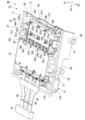
- FIG. 1 is a perspective view showing a motor module according to a first embodiment.
- FIG. 2 is a perspective view showing a portion of the motor module of the first embodiment.
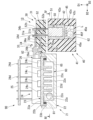
- FIG. 3 is a cross-sectional view showing a part of the power conversion device of the first embodiment.
- FIG. 4 is a cross-sectional view showing a part of the power conversion device of the first embodiment, taken along line IV-IV of FIG.
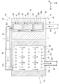
- FIG. 5 is a cross-sectional view showing a part of the power conversion device of the second embodiment.
- the first direction D1 is shown in each figure as appropriate.
- the first direction D1 is the up-down direction of the power conversion device 10.
- the side toward which the arrow of the first direction D1 points (+D1 side) is referred to as "one side of the first direction D1" or "upper side.”
- the side opposite to the side toward which the arrow of the first direction D1 points (-D1 side) is referred to as "the other side of the first direction D1" or "lower side.”
- the second direction D2 is shown in each figure as appropriate.
- the second direction D2 is the left-right direction of the power conversion device 10.
- the second direction D2 intersects with the first direction D1.
- the second direction D2 is perpendicular to the first direction D1.
- the side toward which the arrow of the second direction D2 points (+D2 side) is referred to as the "left side.”
- the side opposite to the side toward which the arrow of the second direction D2 points (-D2 side) is referred to as the "right side.”
- the third direction D3 is shown in each figure as appropriate.
- the third direction D3 is a direction perpendicular to both the first direction D1 and the second direction D2.
- the third direction D3 is the front-to-rear direction of the power conversion device 10.
- the side toward which the arrow of the third direction D3 points (+D3 side) is referred to as the "front side.”
- the side opposite to the side toward which the arrow of the third direction D3 points (-D3 side) is referred to as the "rear side.”
- FIG. 1 is a perspective view showing a motor module 90 of this embodiment.
- the motor module 90 includes a power conversion device 10 and a motor 91.
- the motor 91 is, for example, a drive device mounted on a vehicle to rotate the vehicle's axle.
- the motor 91 is driven by a current supplied from the power conversion device 10.
- the vehicle on which the motor module 90 is mounted is a vehicle that uses the motor 91 as a power source, such as a hybrid electric vehicle (HEV), a plug-in hybrid electric vehicle (PHV), or an electric vehicle (EV).
- HEV hybrid electric vehicle
- PGV plug-in hybrid electric vehicle
- EV electric vehicle
- the power conversion device 10 supplies current to the motor 91.
- the power conversion device 10 generates current to be supplied to the motor 91, and supplies current to each of the U-phase coil, V-phase coil, and W-phase coil of the motor 91.
- the power conversion device 10 includes a housing 11, a holding portion 21, a power module 24, a control board 25, a busbar module 30, a capacitor module 40, and a refrigerant flow path 60.
- the housing 11 accommodates inside thereof each component that constitutes the power conversion device 10, such as the holding portion 21, the power module 24, the control board 25, the bus bar module 30, and the capacitor module 40.
- the housing 11 is in the shape of a substantially rectangular parallelepiped box. When viewed from the first direction D1, the housing 11 is in the shape of a substantially rectangle with its long side extending in the second direction D2.
- the housing 11 has a first housing 12 and a second housing 13.
- the first housing 12 is box-shaped and opens to the top (-D3 side).
- the first housing 12 has a peripheral wall portion 12a and a bottom wall portion 12b.
- the peripheral wall portion 12a is a square tube that protrudes in the first direction D1.
- the peripheral wall portion 12a surrounds the holding portion 21, the power module 24, the control board 25, the busbar module 30, and the capacitor module 40 in the second direction D2 and the third direction D3.
- the first pipe 61 and the fourth pipe 66 extending in the third direction D3 are provided in the wall portion of the peripheral wall portion 12a that is located on the front side (+D3 side) and extends in the second direction D2.
- the first pipeline 61 is disposed to the right (-D2 side) of the fourth pipeline 66.
- the front (+D3 side) portions of the first pipeline 61 and the fourth pipeline 66 protrude forward from the peripheral wall portion 12a.
- the supply pipe portion 71 is connected to the front end of the first pipeline 61.
- the discharge pipe portion 72 is connected to the front end of the fourth pipeline 66.
- the rear (-D3 side) portions of the first pipeline 61 and the fourth pipeline 66 protrude rearward from the peripheral wall portion 12a.
- the rear end of the first pipeline 61 is connected to the capacitor module 40.
- the rear end of the fourth pipeline 66 is connected to the holding portion 21.
- a refrigerant L flows inside the first pipeline 61 and the fourth pipeline 66.
- the bottom wall portion 12b is a plate-like member that extends in a direction perpendicular to the first direction D1.
- the plate surface of the bottom wall portion 12b faces the first direction D1.
- the outer edge of the bottom wall portion 12b is connected to the lower end of the peripheral wall portion 12a.
- the second housing 13 shown in FIG. 1 is box-shaped and opens downward (to the -D1 side).
- the second housing 13 is fixed to the upper end of the first housing 12.
- the holding portion 21 holds the power module 24.
- the holding portion 21 is disposed below the power module 24 (on the -D1 side).
- the power module 24 is fixed to the upper end of the holding portion 21.
- the holding portion 21 has a holding case 22 and a heat sink 23.
- the holding case 22 is a generally rectangular parallelepiped extending in the third direction D3. As shown in FIG. 3, two faces of the holding case 22 face the first direction D1, and the other two faces of the holding case 22 face the second direction D2.
- the holding case 22 is provided with a first recess 22a, a second recess 22b, a third hole 22c, and a fourth hole 22d.
- the first recess 22a is recessed downward from the surface facing the upper side (+D1 side) of the holding case 22. As shown in FIG. 4, the first recess 22a is approximately rectangular when viewed from the first direction D1. As shown in FIG. 3, the second recess 22b is recessed downward from the surface facing the upper side of the holding case 22. Although not shown, when viewed from the first direction D1, the second recess 22b is approximately a square ring shape with its long side extending in the third direction D3. The second recess 22b surrounds the first recess 22a from the outside in both the second direction D2 and the third direction D3.
- the third hole 22c is a hole that is disposed on the rear side (-D3 side) of the wall of the holding case 22 and penetrates the wall extending in the second direction D2 in the third direction D3.
- the outside of the holding case 22 and the inside of the first recess 22a are connected via the third hole 22c.
- the third pipe 64 is connected to the third hole 22c.
- the fourth hole 22d is a hole that is disposed on the front side (+D3 side) of the wall of the holding case 22 and penetrates the wall extending in the second direction D2 in the third direction D3.
- the outside of the holding case 22 and the inside of the first recess 22a are connected via the fourth hole 22d.
- the fourth pipe 66 is connected to the fourth hole 22d.
- the heat sink 23 shown in FIG. 3 transfers heat generated in the power module 24 to the coolant L flowing inside the first recess 22a of the holding case 22.
- the heat sink 23 is made of a metal material such as copper or aluminum.
- the heat sink 23 has a main body portion 23a, a fixing portion 23b, and a number of fin portions 23c.
- the main body 23a is in the form of a plate extending in a direction perpendicular to the first direction D1.
- the plate surface of the main body 23a faces the first direction D1.
- the main body 23a closes the first recess 22a from above (the +D1 side).
- the power module 24 is fixed to the surface of the main body 23a facing upward. In this way, the holding portion 21 holds the power module 24.
- the fixing portion 23b protrudes downward from the outer edge of the main body portion 23a.
- the fixing portion 23b is a substantially square ring shape with its long sides extending in the third direction D3.
- the fixing portion 23b is disposed inside the second recess 22b.
- the fixing portion 23b is fixed to the inner surface of the second recess 22b. In this way, the heat sink 23 is fixed to the holding case 22.
- a sealing member 81 is disposed between the inner circumferential surface of the fixing portion 23b and the inner surface of the second recess 22b.
- the sealing member 81 contacts both the inner circumferential surface of the fixing portion 23b and the inner surface of the second recess 22b. In this way, the sealing member 81 seals between the heat sink 23 and the holding case 22.
- Each of the fins 23c protrudes downward from the main body 23a.
- Each fin 23c is disposed inside the first recess 22a.
- each fin 23c is disposed at intervals from each other along each of the second direction D2 and the third direction D3.
- Each fin 23c may be disposed at intervals from each other along only one of the second direction D2 or the third direction D3.
- each fin 23c is disposed at intervals from a surface facing the upper side (+D1 side) of the first recess 22a in the first direction D1.
- Each fin 23c may be in contact with a surface facing the upper side of the first recess 22a.
- the heat sink 23 does not have to have fins 23c.
- the holding portion 21 is provided with a second flow path 65 through which the refrigerant L flows.
- the second flow path 65 is formed by the inner surface of the first recess 22a, the surface facing downward of the main body portion 23a, and the outer surfaces of each fin portion 23c. Each fin portion 23c protrudes into the second flow path 65. Each fin portion 23c comes into contact with the refrigerant L flowing through the second flow path 65.
- the power module 24 generates a current of a predetermined waveform from a current supplied by an external power source (not shown), and supplies the current to the motor 91. More specifically, the power conversion device 10 generates phase currents (U-phase current, V-phase current, and W-phase current) to be supplied to the U-phase coil, V-phase coil, and W-phase coil (not shown) of the motor 91, respectively. In this embodiment, the power conversion device 10 is an inverter that converts DC current to AC current.
- the power module 24 has a power semiconductor element 24c and a second connection terminal 26.
- the power semiconductor element 24c generates a current of a predetermined waveform from a current supplied by an external power source (not shown). As a result, the power semiconductor element 24c performs power conversion. In this embodiment, the power semiconductor element 24c converts DC current into AC current, for example. In this embodiment, the power semiconductor element 24c is an electronic element such as a metal oxide semiconductor field effect transistor (MOSFET) and an insulated gate bipolar transistor (IGBT).
- the power module 24 has a plurality of power semiconductor elements 24c. Although not shown, in this embodiment, the power module 24 has six power semiconductor elements 24c. Each of a pair of power semiconductor elements 24c generates one of the phase currents, a U-phase current, a V-phase current, and a W-phase current.
- the second connection terminal 26 electrically connects the power semiconductor element 24c arranged inside the power module 24 to the bus bar module 30.
- the second connection terminal 26 is plate-shaped and protrudes to the right (-D2 side) from the power module 24.
- the plate surface of the second connection terminal 26 faces the first direction D1.
- the second connection terminal 26 is made of metal.
- the power module 24 has six second connection terminals 26.
- the six second connection terminals 26 include three second positive terminals 26a and three second negative terminals 26b.
- the second positive electrode terminals 26a are spaced apart from each other in the third direction D3.
- the second positive electrode terminals 26a are electrically connected to a pair of power semiconductor elements 24c that are different from each other.
- the second negative electrode terminals 26b are spaced apart from each other in the third direction D3.
- the second negative electrode terminals 26b are positioned at a position offset from the second positive electrode terminals 26a in the third direction D3.
- the second negative electrode terminals 26b are positioned above the second positive electrode terminals 26a (on the +D1 side).
- the second negative electrode terminals 26b are electrically connected to a pair of power semiconductor elements 24c that are different from each other.
- the output terminal 95 is a plate-like shape that protrudes from the power module 24 to the left (+D2 side).
- the output terminal 95 is made of metal.
- the right end (+D2 side) of the output terminal 95 is electrically connected to the power semiconductor element 24c of the power module 24.
- the left end of the output terminal 95 is connected to a terminal connected to the coil of the motor 91.
- a phase current is supplied from the power module 24 to the coil of the motor 91.
- the power module 24 has three output terminals 95.
- the output terminals 95 are arranged side by side in the third direction D3. One of the U-phase current, the V-phase current, and the W-phase current flows through each output terminal 95.
- the control board 25 is a printed circuit board that extends in a direction perpendicular to the first direction D1. When viewed from the first direction D1, the control board 25 has a generally rectangular shape with its long sides extending in the third direction D3.
- the control board 25 drives the power semiconductor elements 24c.
- a plurality of electronic elements such as ICs (Integrated Circuits) and resistors are mounted on the control board 25.
- the control board 25 is disposed above the heat sink 23 (on the +D1 side).
- the control board 25 is supported in the first direction D1 by a plurality of connection pins 24d. Each connection pin 24d is conductive. Each connection pin 24d electrically connects the power module 24 and the control board 25. This electrically connects each power semiconductor element 24c and the control board 25.
- the control board 25 controls the power conversion of the power module 24 by providing a control pulse to each power semiconductor element 24c.
- the busbar module 30 is disposed to the right (-D2 side) of the power module 24 and above (+D1 side) the capacitor module 40.
- the busbar module 30 has a first holding member 31 and multiple busbars 33.
- the first holding member 31 has a generally rectangular parallelepiped shape extending in the third direction D3. Two faces of the first holding member 31 face the first direction D1, and the other two faces of the first holding member 31 face the second direction D2.
- the first holding member 31 is made of resin and has insulating properties.
- the first holding member 31 is molded by insert molding using a plurality of bus bars 33 as insert members. In this way, the first holding member 31 holds each bus bar 33.
- the first holding member 31 is provided with a first through hole 31a and a second through hole 31b.
- Each of the first through hole 31a and the second through hole 31b is a hole that penetrates the first holding member 31 in the first direction D1.
- the first through hole 31a is provided to the left (+D2 side) of the second through hole 31b.
- the first through hole 31a is approximately rectangular when viewed from the first direction D1.
- three first through holes 31a are provided in the first holding member 31.
- Each first through hole 31a is provided at intervals from each other along the third direction D3.
- the second through hole 31b is approximately rectangular when viewed from the first direction D1.
- three second through holes 31b are provided in the first holding member 31.
- Each second through hole 31b is provided at intervals from each other along the third direction D3.
- each second through hole 31b is positioned offset from the first through holes 31a in the third direction D3.
- the multiple bus bars 33 electrically connect the power module 24 and the capacitor module 40.
- Each bus bar 33 is a plate-shaped member.
- the multiple bus bars 33 include a first bus bar 34 and a second bus bar 35.
- the first bus bar 34 has a first body portion 34a and a first protrusion portion 34b.
- the first body portion 34a is held on the surface facing the upper side (+D1 side) of the first holding member 31.
- the first body portion 34a is a plate-like shape extending in a direction perpendicular to the first direction D1.
- the front end (+D3 side) of the first body portion 34a is located forward of the second connection terminal 26 arranged at the frontmost side, and is electrically connected to the cathode side of an external power source (not shown).
- the left side (+D2 side) of the first body portion 34a is fixed to each second negative terminal 26b by a bolt 82.
- the first bus bar 34 is electrically connected to each second negative terminal 26b.
- the first body portion 34a is provided with a hole portion 34d.
- the hole 34d is a hole that penetrates the first main body portion 34a in the first direction D1. As shown in FIG. 2, the hole 34d is substantially rectangular when viewed from the first direction D1. In this embodiment, three hole portions 34d are provided in the first main body portion 34a. The hole portions 34d are provided at intervals from each other along the third direction D3. When viewed from the first direction D1, the hole portions 34d surround different first through holes 31a.
- the second bus bar 35 has a second body portion 35a and a second protrusion portion 35b.
- the second body portion 35a passes through the inside of the first holding member 31 in the second direction D2.
- the second body portion 35a is a plate-like portion extending in a direction perpendicular to the first direction D1.
- the front end (+D3 side) of the second body portion 35a is located forward of the second connection terminal 26 arranged at the frontmost side, and is electrically connected to the positive side of an external power source (not shown).
- the left side (+D2 side) part of the second body portion 35a is fixed to each second positive terminal 26a by a bolt 82.
- the second bus bar 35 is electrically connected to each second positive terminal 26a.
- the first bus bar 34 is electrically connected to each second negative terminal 26b.
- the bus bar 33 is electrically connected to the second connection terminal 26.
- the second protrusion 35b is a plate-like member that protrudes upward (towards +D1) from the end of the right side (-D2 side) of the second main body 35a.
- the plate surface of the second protrusion 35b faces the second direction D2.
- the second busbar 35 has three second protrusions 35b.
- the second protrusions 35b are arranged at intervals from one another along the third direction D3.
- the second protrusions 35b pass through different first through holes 31a and holes 34d in the first direction D1.
- the upper end of each second protrusion 35b is located above the first main body 34a.
- the capacitor module 40 is disposed below the busbar module 30 (-D1 side).
- the capacitor module 40 has a case portion 41 and a capacitor element 50.
- the case portion 41 houses the capacitor element 50 inside.
- the case portion 41 has a first case portion 42, a second case portion 45, and a first flow path 62.
- the first case portion 42 is a substantially rectangular parallelepiped extending in the third direction D3. As shown in FIG. 3, two faces of the first case portion 42 face the first direction D1, and the other two faces of the first case portion 42 face the second direction D2.
- the first case portion 42 is made of metal.
- the first case portion 42 is provided with a first storage portion 42a and a plurality of protrusions 42c.
- the first storage section 42a is recessed downward from the upper side of the first case section 42, i.e., the surface facing one side (+D1 side) of the first direction D1, i.e., the other side (-D1 side) of the first direction D1.
- the first storage section 42a when viewed from the first direction D1, has a generally rectangular shape with its long side extending in the third direction D3.
- three first storage sections 42a are provided in the first case section 42.
- the first storage sections 42a are provided at intervals from each other along the third direction D3.
- each of the multiple protrusions 42c protrudes downward from the first case portion 42.
- the protrusions 42c are heat dissipation fins.
- the protrusions 42c are arranged at intervals from each other along each of the second direction D2 and the third direction D3.
- the protrusions 42c may be arranged at intervals from each other along only one of the second direction D2 or the third direction D3.
- the protrusions 42c protrude into the inside of the first flow path 62. Note that the first case portion 42 does not necessarily have to be provided with the protrusions 42c.
- the second case portion 45 is a substantially rectangular parallelepiped extending in the third direction D3. As shown in FIG. 3, two faces of the second case portion 45 face the first direction D1, and the other two faces of the second case portion 45 face the second direction D2.
- the second case portion 45 is provided with a second storage portion 45a, a first hole portion 45e, and a second hole portion 45f.
- the second housing portion 45a is a recess recessed downward (-D1 side) from the surface facing the upper side (+D1 side) of the second case portion 45.
- the second housing portion 45a when viewed from the first direction D1, the second housing portion 45a has a substantially rectangular shape with its long side extending in the third direction D3.
- the first case portion 42 is housed inside the second housing portion 45a.
- the lower end of the second housing portion 45a is located lower than the lower end of the first case portion 42.
- the second case portion 45 is made of resin.
- the second case portion 45 is molded by insert molding using the first case portion 42 as an insert member. As a result, the first case portion 42 is fixed to the inner side surface of the second housing portion 45a.
- the first hole 45e is located on the front side (+D3 side) of the wall of the second case portion 45, and is a hole that penetrates the wall portion extending in the second direction D2 in the third direction D3. As shown in FIG. 3, the first hole 45e is provided below the first case portion 42 (-D1 side). As shown in FIG. 4, the first pipe 61 is connected to the first hole 45e.
- the second hole 45f is located on the rear side (-D3 side) of the wall of the second case portion 45, and is a hole that penetrates the wall portion extending in the second direction D2 in the third direction D3. As shown in FIG. 3, the second hole 45f is provided below the first case portion 42 (-D1 side). As shown in FIG. 4, the second pipe 63 is connected to the second hole 45f.
- the first flow path 62 is a flow path through which the refrigerant L flows. As shown in FIG. 3, the first flow path 62 is formed by the outer surface of the first case portion 42 and the inner surface of the second storage portion 45a. The first flow path 62 is connected to the outside of the second case portion 45 via the first hole portion 45e. The first flow path 62 is connected to the outside of the second case portion 45 via the second hole portion 45f.
- the capacitor element 50 acts as a smoothing capacitor that smoothes the current supplied to the power module 24 from an external power source (not shown).
- the capacitor module 40 has a plurality of capacitor elements 50.
- the capacitor module 40 has three capacitor elements 50.
- the number of capacitor elements 50 in the capacitor module 40 may be two or less, or may be four or more.
- each capacitor element 50 has a capacitor body portion 51 and a first connection terminal 52.
- the capacitor body 51 is generally rectangular. As shown in Figures 3 and 4, each capacitor body 51 is housed inside a different first housing portion 42a. In this embodiment, each capacitor element 50 is arranged at intervals from each other along the direction in which the first flow path 62 extends (third direction D3). Each capacitor body 51 is fixed to the inner surface of the first housing portion 42a. This allows the case portion 41 to hold multiple capacitor elements 50.
- the outer surface of each capacitor body 51 is made of an insulating material, such as resin. This makes the outer surface of each capacitor body 51 insulating.
- the first connection terminal 52 electrically connects the capacitor body 51 and the bus bar 33.
- the first connection terminal 52 extends upward from the capacitor body 51, i.e., to one side (+D1 side) in the first direction D1.
- the first connection terminal 52 is conductive.
- each capacitor element 50 has two first connection terminals 52.
- the two first connection terminals 52 include a first positive terminal 52a and a first negative terminal 52b.
- the first positive terminals 52a of the capacitor elements 50 pass through the different first through holes 31a in the first direction D1.
- the first positive terminals 52a are fixed to the different second protrusions 35b of the second bus bar 35. This electrically connects the capacitor elements 50 to the second bus bar 35.
- the first negative terminals 52b are disposed to the right (-D3 side) of the first positive terminals 52a.
- the first negative terminals 52b of the capacitor elements 50 pass through the different second through holes 31b in the first direction D1.
- the first negative terminals 52b are fixed to the different first protrusions 34b of the second bus bar 35. This electrically connects the capacitor elements 50 to the first bus bar 34. As described above, the capacitor elements 50 are electrically connected to the second bus bar 35.
- the bus bar 33 is electrically connected to the first connection terminals 52 of the capacitor elements 50. As described above, the bus bar 33 is electrically connected to the second connection terminal 26. Therefore, the bus bar 33 electrically connects the first connection terminal 52 and the second connection terminal 26.
- the first connection terminal 52 and the bus bar 33 are fixed by welding.
- the first connection terminal 52 and the bus bar 33 may also be fixed by a fastening member such as a bolt.
- the refrigerant flow path 60 shown in FIG. 4 is a flow path that supplies the refrigerant L to the first flow path 62 and the second flow path 65.
- the refrigerant flow path 60 is provided with a pump and a cooler (not shown).
- the pump pressurizes the refrigerant L.
- the cooler cools the refrigerant L.
- the refrigerant L is a liquid such as water or oil.
- the refrigerant flow path 60 has a first pipeline 61, a first flow path 62, a second pipeline 63, a third pipeline 64, a second flow path 65, and a fourth pipeline 66.
- each of the first pipeline 61, the second pipeline 63, the third pipeline 64, and the fourth pipeline 66 is a pipe.
- the refrigerant L flows in the order of the first pipeline 61, the first flow path 62, the second pipeline 63, the third pipeline 64, the second flow path 65, and the fourth pipeline 66.
- the refrigerant L may flow through the fourth line 66, the second flow path 65, the third line 64, the second line 63, the first flow path 62, and the first line 61 in that order.
- the first pipeline 61 is fixed to the first hole 45e. As a result, the first pipeline 61 is connected to the first flow path 62 via the first hole 45e.
- the first flow path 62 connects the first pipeline 61 and the second pipeline 63.
- the refrigerant L flows from the front side (+D3 side) to the rear side (-D3 side).
- each protrusion 42c provided on the first case portion 42 protrudes into the first flow path 62.
- Each protrusion 42c comes into contact with the refrigerant L flowing through the first flow path 62. This increases the contact area between the refrigerant L flowing through the first flow path 62 and the first case portion 42.
- the second pipeline 63 connects the first flow path 62 and the third pipeline 64.
- One end of the second pipeline 63 is fixed to the second hole 45f.
- the second pipeline 63 is connected to the first flow path 62 via the second hole 45f.
- the other end of the second pipeline 63 is connected to one end of the third pipeline 64.
- the third pipeline 64 connects the second pipeline 63 and the second flow path 65.
- the other end of the third pipeline 64 is fixed to the third hole 22c.
- the third pipeline 64 is connected to the second flow path 65 via the third hole 22c.
- the second flow path 65 connects the third pipeline 64 and the fourth pipeline 66.
- the coolant L flows from the rear side (-D3 side) to the front side (+D3 side).
- each of the multiple fin portions 23c of the heat sink 23 protrudes into the second flow path 65.
- Each fin portion 23c comes into contact with the coolant L flowing through the second flow path 65.
- the fourth pipeline 66 is fixed to the fourth hole portion 22d. This connects the fourth pipeline 66 to the second flow path 65.
- the coolant L that flows from the second flow path 65 into the fourth pipeline 66 is discharged to the outside of the power conversion device 10.
- the power conversion device 10 includes a capacitor module 40 having a capacitor element 50 and a case portion 41 that houses the capacitor element 50, a power module 24 having a power semiconductor element 24c that performs power conversion, a control board 25 that drives the power module 24, and a bus bar module 30 having a bus bar 33.
- the capacitor element 50 has a capacitor body portion 51 and a first connection terminal 52 that extends upward from the capacitor body portion 51, i.e., to one side (+D1 side) of the first direction D1, the power module 24 has a second connection terminal 26, and the bus bar 33 electrically connects the first connection terminal 52 and the second connection terminal 26.
- the case portion 41 is recessed from the upper side to the lower side, i.e., to the other side (-D1 side) of the first direction D1, and has a first housing portion 42a that houses the capacitor body portion 51, and a first flow path 62 through which the refrigerant L flows. Therefore, since the case portion 41 in which the capacitor body portion 51 is housed has the first flow path 62, the thermal resistance between the capacitor element 50 and the first flow path 62 can be reduced compared to when the first flow path 62 is provided in a member different from the case portion 41. This makes it possible to increase the amount of heat transferred from the capacitor element 50 to the refrigerant L flowing through the first flow path 62. This makes it possible to prevent the temperature of the capacitor element 50 from becoming too high. This makes it possible to prevent the capacitor element 50 from deteriorating.
- the shape and configuration of the housing 11 can be simplified compared to when the first flow path 62 is provided in the housing 11. This makes it possible to prevent an increase in the manufacturing cost of the housing 11. Therefore, it is possible to prevent an increase in the manufacturing cost of the power conversion device 10.
- the capacitor module 40 and the bus bar module 30 can be manufactured separately, and then the capacitor element 50 and the bus bar 33 can be electrically connected. This makes it easy to reduce the number of parts in the insert members of each module 30, 40. This makes it easy to prevent an increase in the labor required to manufacture each module 30, 40, which in turn helps prevent an increase in the labor required to manufacture the power conversion device 10.
- the capacitor module 40, the bus bar module 30, and the power module 24 can be manufactured in parallel during the manufacturing process of the power conversion device 10, making it easier to effectively prevent an increase in the number of manufacturing steps for the power conversion device 10.
- the case portion 41 has a first case portion 42 in which the first storage portion 42a is provided, and a second case portion 45 in which the second storage portion 45a that houses the first case portion 42 is provided, and the first flow path 62 is formed by the outer surface of the first case portion 42 and the inner surface of the second case portion 45. Therefore, the refrigerant L flowing through the first flow path 62 can be directly contacted with the first case portion 42 that houses the capacitor body portion 51. This makes it possible to more suitably increase the amount of heat transferred from the capacitor element 50 to the refrigerant L flowing through the first flow path 62. Therefore, it is possible to more suitably prevent the temperature of the capacitor element 50 from becoming too high. Therefore, it is possible to more suitably prevent the capacitor element 50 from deteriorating.
- the first case portion 42 is made of metal. Therefore, the thermal conductivity of the first case portion 42 can be increased compared to when the first case portion 42 is made of resin. This makes it possible to more suitably increase the amount of heat transferred from the capacitor element 50 to the refrigerant L flowing through the first flow path 62. Therefore, it is possible to more suitably prevent the temperature of the capacitor element 50 from becoming too high.
- the first case portion 42 is provided with a plurality of protrusions 42c that protrude into the inside of the first flow path 62. Therefore, as described above, the contact area between the refrigerant L flowing through the first flow path 62 and the first case portion 42 can be increased. This makes it possible to more suitably increase the amount of heat transferred from the capacitor element 50 to the refrigerant L flowing through the first flow path 62. Therefore, it is possible to more suitably prevent the temperature of the capacitor element 50 from becoming too high.
- the second case portion 45 is made of resin and is molded by insert molding using the first case portion 42 as an insert member. Therefore, the case portion 41 is easy to manufacture, and an increase in the manufacturing steps and manufacturing costs of the capacitor module 40 can be suppressed.
- the busbar module 30 has a plurality of busbars 33 and a first holding member 31 made of resin that holds the plurality of busbars 33, and the first holding member 31 is molded by insert molding using the plurality of busbars 33 as insert members. Therefore, the busbar module 30 can be easily manufactured, and an increase in the manufacturing man-hours and manufacturing costs of the busbar module 30 can be suppressed.
- the bus bars 33 include a first bus bar 34 and a second bus bar 35 through which currents of approximately equal magnitude flow in opposite directions.
- a part of the first holding member 31 having insulation is disposed between the first bus bar 34 and the second bus bar 35, so that the first bus bar 34 and the second bus bar 35 can be easily disposed close to each other. Therefore, the mutual inductance generated by the current flowing through the first bus bar 34 and the current flowing through the second bus bar 35 acts to cancel the self-inductance, and the parasitic inductance generated in each bus bar 33 can be reduced.
- This makes it possible to suppress an increase in surge noise generated by the switching operation of the power semiconductor element 24c of the power module 24. Therefore, it is possible to suppress an increase in the size of a noise filter provided to remove noise generated in the power module 24. This makes it possible to suppress an increase in the size of the power conversion device 10 and an increase in the manufacturing cost of the power conversion device 10.
- the first connection terminal 52 and the bus bar 33 are fixed by welding. Therefore, compared to a case where the first connection terminal 52 and the bus bar 33 are fixed by a fastening member such as a bolt, no space is required to arrange the fastening member. This makes it easier to prevent the capacitor module 40 and the bus bar module 30 from becoming larger. This makes it possible to more effectively prevent the power conversion device 10 from becoming larger.
- the manufacturing process of the power conversion device 10 does not require a process for measuring the tightening torque of the fastening member. Therefore, an increase in the manufacturing man-hours for the power conversion device 10 can be more effectively suppressed.
- the first connection terminal 52 and the bus bar 33 are fixed with a fastening member, if the tightening torque of the fastening member is too small, the contact resistance between the first connection terminal 52 and the bus bar 33 increases. This increases the amount of heat generated at the connection portion between the first connection terminal 52 and the bus bar 33.
- the first connection terminal 52 and the bus bar 33 are fixed by welding, so it is easy to prevent an increase in the contact resistance between the first connection terminal 52 and the bus bar 33. Therefore, an increase in the amount of heat generated at the connection portion between the first connection terminal 52 and the bus bar 33 can be prevented.
- the power conversion device 10 includes a holding section 21 that holds the power module 24, and the holding section 21 is provided with a second flow path 65 through which the coolant L flows. Therefore, the thermal resistance between the power module 24 and the second flow path 65 can be reduced compared to when the second flow path 65 is provided in a member different from the holding section 21. This makes it possible to increase the amount of heat transferred from the power module 24 to the coolant L flowing through the second flow path 65. Therefore, it is possible to prevent the temperature of the power module 24 from becoming too high.
- the shape and configuration of the housing 11 can be more suitably simplified compared to when the second flow path 65 is provided in the housing 11. This makes it possible to more suitably prevent an increase in the manufacturing cost of the housing 11. Therefore, it is possible to more suitably prevent an increase in the manufacturing cost of the power conversion device 10.
- a first direction D1 is shown in FIG. 5.
- the first direction D1 is the left-right direction of the power conversion device 210.
- the side toward which the arrow of the first direction D1 points (+D1 side) is referred to as "one side of the first direction D1" or "left side.”
- the side opposite to the side toward which the arrow of the first direction D1 points (-D1 side) is referred to as "the other side of the first direction D1" or "right side.”
- the second direction D2 is shown in FIG. 5.
- the second direction D2 is the up-down direction of the power conversion device 210.
- the second direction D2 intersects with the first direction D1.
- the second direction D2 is perpendicular to the first direction D1.
- the side toward which the arrow of the second direction D2 points (+D2 side) is referred to as the "upper side.”
- the side opposite to the side toward which the arrow of the second direction D2 points (-D2 side) is referred to as the "lower side.”
- the third direction D3 is shown in each figure as appropriate.
- the third direction D3 is the front-to-rear direction of the power conversion device 210.
- the terms upper side, lower side, left side, right side, front side, and rear side are names used simply to describe the relative positional relationships of the various parts, and the actual positional relationships may be other than those indicated by these names.
- FIG. 5 is a cross-sectional view showing a portion of the power conversion device 210 of the motor module 290 of this embodiment.
- the power conversion device 210 includes a housing 11 (not shown), a holding portion 221, a pair of power modules 24, a pair of control boards 25, a bus bar module 230, a capacitor module 240, and a refrigerant flow path 260.
- the holding portion 221 holds the power modules 24. In the second direction D2, the holding portion 221 is disposed between a pair of power modules 24. The power modules 24 are fixed to the upper and lower ends of the holding portion 221.
- the holding portion 221 has a holding case 222 and a pair of heat sinks 23.
- the holding case 222 is a generally rectangular parallelepiped extending in the third direction D3. Two faces of the holding case 222 face the first direction D1, and the other two faces of the holding case 222 face the second direction D2.
- the holding case 222 is provided with a first recess 222a, second recesses 22b, 222b, a third hole 22c, and a fourth hole 22d.
- the first recess 222a is recessed downward from the surface facing the upper side (+D2 side) of the holding case 222. Although not shown, the first recess 222a is approximately rectangular when viewed from the first direction D1. In this embodiment, the first recess 222a opens to the lower side (-D2 side).
- the second recess 22b is recessed downward from the surface facing the upper side of the holding case 222.
- the second recess 222b is recessed upward from the surface facing the lower side of the holding case 222.
- the second recesses 22b, 222b are approximately square ring-shaped with long sides extending in the third direction D3 when viewed from the first direction D1.
- the second recesses 22b, 222b surround the first recess 222a from the outside in each of the second direction D2 and the third direction D3.
- Each of the pair of heat sinks 23 transfers heat generated in the power module 24 to the refrigerant L flowing through the second flow path 265.
- One of the heat sinks 223a is arranged above the holding case 222 (on the +D2 side).
- the other heat sink 223b is arranged below the holding case 222 (on the -D2 side).
- the shapes of the heat sinks 223a and 223b are plane-symmetrical with respect to a plane that is perpendicular to the second direction D2 and passes between the pair of heat sinks 223a and 223b.
- the fixing portion 23b of one heat sink 223a is disposed inside the second recess 22b and is fixed to the inner surface of the second recess 22b.
- the fixing portion 23b of the other heat sink 223b is disposed inside the second recess 222b and is fixed to the inner surface of the second recess 222b. In this way, the pair of heat sinks 23 are fixed to the holding case 222.
- Each fin portion 23c of one heat sink 223a protrudes downward (-D2 side) from the main body portion 23a.
- Each fin portion 23c of the other heat sink 223b protrudes upward (+D2 side) from the main body portion 23a.
- Each fin portion 23c is disposed inside the first recess 222a.
- the holding portion 221 is provided with a second flow path 265 through which the refrigerant L flows.
- the second flow path 265 is formed by the inner surface of the first recess 222a, the surface facing the lower side of the main body portion 23a of one heat sink 223a, the surface facing the upper side of the main body portion 23a of the other heat sink 223b, and the outer surfaces of each fin portion 23c.
- Each fin portion 23c comes into contact with the refrigerant L flowing through the second flow path 265.
- Other configurations of the holding portion 221 of this embodiment are similar to the other configurations of the holding portion 21 of the first embodiment described above.
- Each of the pair of power modules 24 generates a current of a predetermined waveform from a current supplied by an external power source (not shown), and supplies the current to the motor 91.
- Each power module 24 has a power semiconductor element 24c and a second connection terminal 26.
- the configurations of the power semiconductor element 24c and the second connection terminal 26 of this embodiment are similar to the configurations of the power semiconductor element 24c and the second connection terminal 26 of the first embodiment described above.
- the second connection terminals 26 electrically connect the power semiconductor elements 24c arranged inside the power module 24 to the busbar module 30.
- one power module 224a has six second connection terminals 226a.
- the six second connection terminals 226a include three second positive terminals 26a and three second negative terminals 26b.
- the other power module 224b has six second connection terminals 226b.
- the six second connection terminals 226b include three second positive terminals 26a and three second negative terminals 26b.
- Each second positive terminal 26a is electrically connected to a different pair of power semiconductor elements 24c.
- Each second negative terminal 26b is electrically connected to a different pair of power semiconductor elements 24c.
- a current is supplied from the busbar module 230 to each pair of power semiconductor elements 24c via the second connection terminals 26.
- the other configurations of the power module 24 are similar to those of the power module 24 of the first embodiment described above.
- the control board 225a that drives the power module 224a is disposed above the heat sink 223a (on the +D2 side).
- the control board 225b that drives the power module 224b is disposed below the heat sink 223b (on the -D2 side).
- the connection pin 24d electrically connects the power module 224a to the control board 225a. This electrically connects each power semiconductor element 24c of the power module 224a to the control board 225a.
- the connection pin 24d electrically connects the power module 224b to the control board 225b. This electrically connects each power semiconductor element 24c of the power module 224b to the control board 225b.
- Each control board 25 controls the power conversion of each power module 24 by providing a control pulse to each power semiconductor element 24c.
- the busbar module 230 is disposed to the right (-D1 side) of the power module 24 and to the left (+D1 side) of the capacitor module 40.
- the busbar module 230 has a first holding member 231 and multiple busbars 233.
- the first holding member 231 has a generally rectangular parallelepiped shape extending in the third direction D3. Two faces of the first holding member 231 face the first direction D1, and the other two faces of the first holding member 231 face the second direction D2.
- the first holding member 231 is made of resin and has insulating properties.
- the first holding member 231 is molded by insert molding using a plurality of bus bars 233 as insert members. In this way, the first holding member 231 holds each bus bar 233.
- a first through hole 231a is provided in the first holding member 231.
- the first through holes 231a are holes that penetrate the first holding member 231 in the first direction D1.
- three first through holes 231a are provided in the first holding member 231.
- each first through hole 231a is provided at intervals from each other along the third direction D3.
- the multiple bus bars 233 electrically connect the power module 24 and the capacitor module 240.
- Each bus bar 233 is a plate-shaped member.
- the multiple bus bars 233 include a first bus bar 234 and a second bus bar 235.
- the first bus bar 234 has a first body portion 234a and a first protrusion portion 234h.
- the first body portion 234a is held by the first holding member 231.
- the first body portion 234a is a plate-shaped member.
- the front end (+D3 side) of the first body portion 234a is located forward of the second connection terminal 26 located at the frontmost side.
- the rear end (-D3 side) of the first body portion 234a is located rear of the second connection terminal 26 located at the rearmost side.
- the first body portion 234a has a first portion 234b, a second portion 234c, and a third portion 234d.
- the first portion 234b and the second portion 234c are each in the form of a plate protruding in the first direction D1.
- the plate surfaces of the first portion 234b and the second portion 234c face the second direction D2.
- the left side (+D1 side) of the first portion 234b is fixed to each second negative terminal 26b of one power module 224a by a bolt 82.
- the left side (+D1 side) of the second portion 234c is fixed to each second negative terminal 26b of the other power module 224b by a bolt 82.
- the first bus bar 234 is electrically connected to the pair of power modules 24.
- the third portion 234d is plate-shaped and extends in the second direction D2.
- the plate surface of the third portion 234d faces the first direction D1.
- the upper end of the third portion 234d is connected to the right end (-D1 side) of the first portion 234b.
- the lower end of the third portion 234d is connected to the right end of the second portion 234c.
- a first hole 234e and a second hole 234f are provided in the third portion 234d.
- Each of the first hole 234e and the second hole 234f is a hole that penetrates the third portion 234d in the first direction D1.
- the first hole 234e is provided above (towards +D2) the second hole 234f.
- three first holes 234e are provided.
- the first holes 234e are provided at intervals from each other in the third direction D3.
- three second holes 234f are provided.
- the second holes 234f are provided at intervals from each other in the third direction D3.
- the first protrusion 234h is a plate-like member that protrudes from the third portion 234d to the left (+D1 side).
- the plate surface of the first protrusion 234h faces the second direction D2.
- the first bus bar 234 has three first protrusions 234h.
- the first protrusions 234h are arranged at intervals from each other along the third direction D3.
- the other configurations of the first bus bar 234 are similar to the other configurations of the first bus bar 34 of the first embodiment described above.
- the second bus bar 235 has a second body portion 235a and a second protrusion portion 235h.
- the second body portion 235a is held by the first holding member 231.
- the second body portion 235a is a plate-shaped member.
- the front end (+D3 side) of the second body portion 235a is located forward of the second connection terminal 26 that is located at the frontmost side.
- the rear end (-D3 side) of the second body portion 235a is located rear of the second connection terminal 26 that is located at the rearmost side.
- the second body portion 235a has a fourth portion 235b, a fifth portion 235c, and a sixth portion 235d.
- the fourth portion 235b and the fifth portion 235c are each in the form of a plate protruding in the first direction D1.
- the plate surfaces of the fourth portion 235b and the fifth portion 235c face the second direction D2.
- the left side (+D1 side) of the fourth portion 235b is fixed to each second positive terminal 26a of one power module 224a by a bolt 82.
- the left side (+D1 side) of the fifth portion 235c is fixed to each second positive terminal 26a of the other power module 224b by a bolt 82.
- the second bus bar 235 is electrically connected to the pair of power modules 24.
- the sixth portion 235d is in the shape of a plate extending in the second direction D2.
- the plate surface of the sixth portion 235d faces the first direction D1.
- the upper end of the sixth portion 235d is connected to the right end (-D1 side) of the fourth portion 235b.
- the lower end of the sixth portion 235d is connected to the right end of the fifth portion 235c.
- the sixth portion 235d is provided with a third hole 235e and a fourth hole 235f.
- the third hole 235e and the fourth hole 235f are holes that penetrate the sixth portion 235d in the first direction D1.
- the third hole 235e is provided above the fourth hole 235f (on the +D2 side).
- three third holes 235e are provided.
- the third holes 235e are provided at intervals from each other in the third direction D3.
- three fourth holes 235f are provided.
- the fourth holes 235f are provided at intervals from each other in the third direction D3.
- a portion of the third hole 235e overlaps with a portion of the first hole 234e.
- a portion of the fourth hole 235f overlaps with a portion of the second hole 234f.
- the second protrusion 235h is plate-shaped and protrudes from the sixth portion 235d to the left (+D1 side).
- the plate surface of the second protrusion 235h faces the second direction D2.
- the second bus bar 235 has three second protrusions 235h.
- the second protrusions 235h are arranged at intervals from each other along the third direction D3.
- the other configurations of the second bus bar 235 of this embodiment are similar to the other configurations of the second bus bar 35 of the first embodiment described above.
- the capacitor module 240 is disposed to the right (-D1 side) of the busbar module 230.
- the capacitor module 240 has a case portion 41 and a capacitor element 50.
- the capacitor module 240 of this embodiment is disposed in a state in which the capacitor module 40 of the first embodiment is rotated 90° counterclockwise around an axis extending in the third direction D3. Therefore, the first storage portion 42a is recessed to the right from the left side of the first case portion 42, that is, the surface facing one side (+D1 side) of the first direction D1, that is, the other side (-D1 side) of the first direction D1.
- Each protrusion 42c protrudes into the inside of the first flow path 62.
- the second storage portion 45a is recessed to the right from the surface facing the left side of the second case portion 45.
- the first flow path 62 is formed by the outer surface of the first case portion 42 and the inner surface of the second storage portion 45a.
- the other configuration of the case part 41 is similar to the other configuration of the case part 41 of the first embodiment described above.
- Each capacitor body 51 is housed inside a different first housing 42a.
- the first connection terminal 52 extends from the capacitor body 51 to the left, i.e., to one side (+D1 side) of the first direction D1.
- the two first connection terminals 52 include a first positive terminal 52a and a first negative terminal 52b.
- the first positive electrode terminals 52a of the capacitor elements 50 are passed through the first through holes 231a different from each other in the first direction D1.
- the first positive electrode terminals 52a are passed through the first hole 234e of the first bus bar 234 and the third hole 235e of the second bus bar 235 in the first direction D1, and are fixed to the second protrusions 235h different from each other of the second bus bar 235. This electrically connects the capacitor elements 50 and the second bus bar 235.
- the first negative electrode terminals 52b of the capacitor elements 50 are passed through the first through holes 231a different from each other in the first direction D1.
- the first positive electrode terminals 52a are passed through the second hole 234f of the first bus bar 234 and the fourth hole 235f of the second bus bar 235 in the first direction D1, and are fixed to the first protrusions 234h different from each other of the first bus bar 234.
- the first connection terminal 52 and the bus bar 233 are fixed by welding.
- the other configurations of the capacitor module 240 of this embodiment are similar to the other configurations of the capacitor module 40 of the first embodiment described above.
- the refrigerant flow path 260 in this embodiment is a flow path that supplies the refrigerant L to the first flow path 62 and the second flow path 265.
- the refrigerant flow path 260 has a first pipeline 61 (see FIG. 4), a first flow path 62, a second pipeline 63 (see FIG. 4), a third pipeline 64 (see FIG. 4), a second flow path 265, and a fourth pipeline 66 (see FIG. 4).
- the second flow path 265 connects the third pipeline 64 and the fourth pipeline 66 shown in FIG. 4.
- the refrigerant L flows from the rear side (-D3 side) to the front side (+D3 side).
- each of the multiple fin portions 23c of the pair of heat sinks 23 comes into contact with the refrigerant L flowing through the second flow path 265. This increases the contact area between the refrigerant L flowing through the second flow path 265 and the pair of heat sinks 23.
- the other configurations of the refrigerant flow path 260 of this embodiment are similar to the configurations of the refrigerant flow path 60 of the first embodiment described above.
- the capacitor element 50 has a capacitor body 51 and a first connection terminal 52 extending from the capacitor body 51 to the left, i.e., to one side (+D1 side) in the first direction, and the case 41 is recessed from the left to the right, i.e., to the other side (-D1 side) in the first direction D1, and has a first housing portion 42a that houses the capacitor body 51 and a first flow path 62 through which the refrigerant L flows. Therefore, compared to a case in which the first flow path 62 is provided in a member different from the case 41, the thermal resistance between the capacitor element 50 and the first flow path 62 can be reduced.
- the shape of the housing 11 can be simplified compared to a configuration in which the first flow path 62 is provided in the housing 11. This makes it possible to prevent an increase in the manufacturing cost of the housing 11.
- the power conversion device 210 includes a holding section 221 that holds the power module 24, and the holding section 221 is provided with a second flow path 265 through which the coolant L flows. Therefore, the thermal resistance between the power module 24 and the second flow path 265 can be reduced compared to when the second flow path 265 is provided in a member different from the holding section 221. This makes it possible to increase the amount of heat transferred from the power module 24 to the coolant L flowing through the second flow path 265. Therefore, it is possible to prevent the temperature of the power module 24 from becoming too high.
- the shape and configuration of the housing 11 can be more suitably simplified compared to when the second flow path 265 is provided in the housing 11. This makes it possible to more suitably prevent the manufacturing costs of the housing 11 from increasing.
- the power module or power semiconductor element may be in direct contact with the refrigerant without a heat sink, as long as insulation is ensured. In this case, the amount of heat transferred from the power semiconductor element to the refrigerant can be further increased.
- the use of the power conversion device of this embodiment is not limited to generating a current to be supplied to a motor that drives a vehicle, but may also generate a current to be supplied to a drive device such as a motor mounted on an electrical appliance.
- the power conversion device may be an inverter that generates an AC current of a predetermined waveform from a DC current supplied from an external power source, or a converter that generates a DC current from an AC current supplied from an external power source.
- a power conversion device including a capacitor module having a capacitor element and a case portion that houses the capacitor element, a power module having a power semiconductor element that performs power conversion, a control board that drives the power module, and a busbar module having a busbar, wherein the capacitor element has a capacitor body portion and a first connection terminal extending from the capacitor body portion to one side in a first direction, the power module has a second connection terminal, the busbar electrically connects the first connection terminal and the second connection terminal, the case portion is recessed from the one side in the first direction to the other side in the first direction, and has a first housing portion that houses the capacitor body portion and a first flow path through which a coolant flows.
- the case portion has a first case portion in which the first housing portion is provided and a second case portion in which a second housing portion that houses the first case portion is provided, and the first flow path is constituted by an outer surface of the first case portion and an inner surface of the second case portion.
- the first case part is made of metal.
- the first case part is provided with a plurality of protrusions protruding into the inside of the first flow path.
- the power conversion device according to any one of (1) to (5), in which the bus bar module has a plurality of the bus bars and a first holding member made of resin that holds the plurality of the bus bars, and the first holding member is molded by insert molding using the plurality of the bus bars as an insert member.
- the power conversion device according to any one of (1) to (6), in which the first connection terminal and the bus bar are fixed by welding.
- (8) The power conversion device according to any one of (1) to (7), in which a holding part that holds the power module is provided, and the holding part is provided with a second flow path through which the coolant flows.
- a motor module comprising a power conversion device according to any one of (1) to (8) and a motor driven by a current supplied from the power conversion device.
Landscapes
- Engineering & Computer Science (AREA)
- Power Engineering (AREA)
- Inverter Devices (AREA)
Abstract
本発明は、コンデンサ素子、およびコンデンサ素子を収容するケース部を有するコンデンサモジュールと、電力変換を行うパワー半導体素子を有するパワーモジュールと、パワーモジュールを駆動する制御基板と、バスバーを有するバスバーモジュールと、を備える。コンデンサ素子は、コンデンサ本体部、およびコンデンサ本体部から第1方向の一方側に延びる第1接続端子を有する。パワーモジュールは、第2接続端子を有する。バスバーは、第1接続端子と第2接続端子とを電気的に接続する。ケース部は、第1方向の一方側から第1方向の他方側に窪み、コンデンサ本体部を収容する第1収容部と、冷媒が流れる第1流路と、を有する。
Description
本発明は、電力変換装置、およびモータモジュールに関する。
モータに電力を供給する電力変換装置として、例えば、パワー半導体を有するパワーモジュールユニット、コンデンサ素子を有するコンデンサユニット、およびコンデンサ素子を冷却する冷媒が流れる冷媒流路を備え、パワーモジュールユニットとコンデンサ素子とがバスバーによって電気的に接続される電力変換装置が開示されている(例えば日本国公開公報:特開2013-031330号)。
特許文献1に記載の電力変換装置では、コンデンサ素子と冷媒流路との間にバスバーが配置されるため、コンデンサ素子と冷媒流路との間の熱抵抗が大きくなり易かった。そのため、コンデンサ素子から冷媒流路を流れる冷媒に伝達される熱量を高めづらく、コンデンサ素子の温度が高くなりすぎる虞があった。これにより、コンデンサ素子の劣化が促進される虞があった。
本発明の一つの態様は、上記事情に鑑みて、コンデンサ素子の温度が高くなりすぎることを抑制できる電力変換装置、およびモータモジュールを提供することを目的の一つとする。
本発明の電力変換装置の一つの態様は、コンデンサ素子、および前記コンデンサ素子を収容するケース部を有するコンデンサモジュールと、電力変換を行うパワー半導体素子を有するパワーモジュールと、前記パワー半導体素子を駆動する制御基板と、バスバーを有するバスバーモジュールと、を備える。前記コンデンサ素子は、コンデンサ本体部、およびコンデンサ本体部から第1方向の一方側に延びる第1接続端子を有する。前記パワーモジュールは、第2接続端子を有する。前記バスバーは、前記第1接続端子と前記第2接続端子とを電気的に接続する。前記ケース部は、前記第1方向の一方側から前記第1方向の他方側に窪み、前記コンデンサ本体部を収容する第1収容部と、冷媒が流れる第1流路と、を有する。
本発明のモータモジュールの一つの態様は、上記の電力変換装置と、前記電力変換装置から供給される電流により駆動するモータと、を備える。
本発明の一つの態様によれば、電力変換装置、およびモータモジュールにおいて、コンデンサ素子の温度が高くなりすぎることを抑制できる。
以下、図面を参照しながら、本発明の実施形態に係る電力変換装置について説明する。なお、本発明の範囲は、以下の実施形態に限定されず、本発明の技術的思想の範囲内で任意に変更可能である。また、以下の図面では、各構成を分かり易くするために、実際の構造と縮尺や数等を異ならせる場合がある。
<第1実施形態>
以下の説明において、各図には適宜、第1方向D1を示す。本実施形態において、第1方向D1は、電力変換装置10の上下方向である。以下の説明では、第1方向D1の矢印が向く側(+D1側)を「第1方向D1の一方側」または「上側」と呼ぶ。第1方向D1の矢印が向く側と反対側(-D1側)を「第1方向D1の他方側」または「下側」と呼ぶ。
以下の説明において、各図には適宜、第1方向D1を示す。本実施形態において、第1方向D1は、電力変換装置10の上下方向である。以下の説明では、第1方向D1の矢印が向く側(+D1側)を「第1方向D1の一方側」または「上側」と呼ぶ。第1方向D1の矢印が向く側と反対側(-D1側)を「第1方向D1の他方側」または「下側」と呼ぶ。
以下の説明において、各図には適宜、第2方向D2を示す。本実施形態において、第2方向D2は、電力変換装置10の左右方向である。第2方向D2は、第1方向D1と交差する。本実施形態において、第2方向D2は、第1方向D1と直交する。以下の説明では、第2方向D2の矢印が向く側(+D2側)を「左側」と呼ぶ。第2方向D2の矢印が向く側と反対側(-D2側)を「右側」と呼ぶ。
以下の説明において、各図には適宜、第3方向D3を示す。第3方向D3は、第1方向D1および第2方向D2の両方と直交する方向である。第3方向D3は、電力変換装置10の前後方向である。以下の説明では、第3方向D3の矢印が向く側(+D3側)を「前側」と呼ぶ。第3方向D3の矢印が向く側と反対側(-D3側)を「後側」と呼ぶ。
なお、上側、下側、左側、右側、前側、および後側は、単に各部の相対位置関係を説明するための名称であり、実際の配置関係等は、これらの名称で示される配置関係等以外の配置関係等であってもよい。
図1は、本実施形態のモータモジュール90を示す斜視図である。モータモジュール90は、電力変換装置10と、モータ91と、を備える。モータ91は、例えば、車両に搭載され、車両の車軸を回転させる駆動装置である。モータ91は、電力変換装置10から供給される電流により駆動する。モータモジュール90が搭載される車両は、ハイブリッド自動車(HEV)、プラグインハイブリッド自動車(PHV)、電気自動車(EV)などのモータ91を動力源とする車両である。
電力変換装置10は、モータ91に電流を供給する。電力変換装置10は、モータ91に供給する電流を生成するとともに、モータ91が有するU相コイル、V相コイル、およびW相コイルのそれぞれに電流を供給する。図2に示すように、電力変換装置10は、ハウジング11と、保持部21と、パワーモジュール24と、制御基板25と、バスバーモジュール30と、コンデンサモジュール40と、冷媒流路60と、を備える。
ハウジング11は、保持部21、パワーモジュール24、制御基板25、バスバーモジュール30、コンデンサモジュール40等の電力変換装置10を構成する各部材を内部に収容する。図1に示すように、ハウジング11は、略直方体状の箱状である。第1方向D1から見て、ハウジング11は、長辺が第2方向D2に延びる略矩形状である。ハウジング11は、第1ハウジング12、および第2ハウジング13を有する。
図2に示すように、第1ハウジング12は、上側(-D3側)に開口する箱状である。第1ハウジング12は、周壁部12a、および底壁部12bを有する。図1に示すように、周壁部12aは、第1方向D1に突出する四角筒状である。周壁部12aは、保持部21、パワーモジュール24、制御基板25、バスバーモジュール30、コンデンサモジュール40を第2方向D2および第3方向D3に囲む。周壁部12aの壁部のうち、前側(+D3側)に位置し、第2方向D2に延びる壁部には、第3方向D3に延びる第1管路61および第4管路66が設けられる。
第1管路61は、第4管路66よりも右側(-D2側)に配置されている。第1管路61および第4管路66それぞれの前側(+D3側)の部分は、周壁部12aよりも前側に突出している。第1管路61の前側の端部には、供給管部71が接続される。第4管路66の前側の端部には、排出管部72が接続される。図2に示すように、第1管路61および第4管路66それぞれの後側(-D3側)の部分は、周壁部12aよりも後側に突出している。図示は省略するが、第1管路61の後側の端部は、コンデンサモジュール40と接続される。第4管路66の後側の端部は、保持部21と接続される。第1管路61および第4管路66の内部には、冷媒Lが流れる。
底壁部12bは、第1方向D1と直交する方向に広がる板状である。底壁部12bの板面は、第1方向D1を向く。底壁部12bの外縁部は、周壁部12aの下端と繋がる。
図1に示す第2ハウジング13は、下側(-D1側)に開口する箱状である。第2ハウジング13は、第1ハウジング12の上端に固定される。
図3に示すように、保持部21は、パワーモジュール24を保持する。保持部21は、パワーモジュール24よりも下側(-D1側)に配置される。保持部21の上端には、パワーモジュール24が固定される。保持部21は、保持ケース22、およびヒートシンク23を有する。
図4に示すように、保持ケース22は、第3方向D3に延びる略直方体状である。図3に示すように、保持ケース22の2つの面は第1方向D1を向き、保持ケース22の他の2つの面は第2方向D2を向く。保持ケース22には、第1凹部22a、第2凹部22b、第3孔部22c、および第4孔部22dが設けられる。
第1凹部22aは、保持ケース22の上側(+D1側)を向く面から下側に窪む。図4に示すように、第1方向D1から見て、第1凹部22aは、略矩形状である。図3に示すように、第2凹部22bは、保持ケース22の上側を向く面から下側に窪む。図示は省略するが、第1方向D1から見て、第2凹部22bは、長辺が第3方向D3に延びる略四角環状である。第2凹部22bは、第1凹部22aを第2方向D2および第3方向D3それぞれの外側から囲む。
図4に示すように、第3孔部22cは、保持ケース22の壁部のうち、後側(-D3側)に配置され、且つ、第2方向D2に延びる壁部を第3方向D3に貫通する孔である。第3孔部22cを介して、保持ケース22の外部と、第1凹部22aの内部とが繋がる。第3孔部22cには、第3管路64が接続される。第4孔部22dは、保持ケース22の壁部のうち、前側(+D3側)に配置され、且つ、第2方向D2に延びる壁部を第3方向D3に貫通する孔である。第4孔部22dを介して、保持ケース22の外部と、第1凹部22aの内部とが繋がる。第4孔部22dには、第4管路66が接続される。
図3に示すヒートシンク23は、パワーモジュール24において発生した熱を保持ケース22の第1凹部22aの内部を流れる冷媒Lに伝達する。本実施形態において、ヒートシンク23は、例えば、銅、およびアルミニウム等の金属材料によって構成される。ヒートシンク23は、本体部23a、固定部23b、および複数のフィン部23cを有する。
本体部23aは、第1方向D1と直交する方向に広がる板状である。本体部23aの板面は、第1方向D1を向く。本体部23aは、第1凹部22aを上側(+D1側)から塞ぐ。本体部23aの上側を向く面には、パワーモジュール24が固定される。これにより、保持部21は、パワーモジュール24を保持する。
固定部23bは、本体部23aの外縁から下側に突出する。図示は省略するが、第1方向D1から見て、固定部23bは、長辺が第3方向D3に延びる略四角環状である。固定部23bは、第2凹部22bの内部に配置される。固定部23bは、第2凹部22bの内面に固定される。これにより、ヒートシンク23は、保持ケース22に固定される。固定部23bの内周面と、第2凹部22bの内面との間には、封止部材81が配置される。封止部材81は、固定部23bの内周面および第2凹部22bの内面の両方と接触する。これにより、封止部材81は、ヒートシンク23と保持ケース22との間を封止する。
複数のフィン部23cのそれぞれは、本体部23aから下側に突出する。各フィン部23cは、第1凹部22aの内部に配置される。図4に示すように、本実施形態において、各フィン部23cは、第2方向D2および第3方向D3のそれぞれに沿って互いに間隔をあけて配置される。各フィン部23cは、第2方向D2または第3方向D3のいずれか一方のみに沿って互いに間隔をあけて配置されていてもよい。図3に示すように、本実施形態において、各フィン部23cは、第1凹部22aの上側(+D1側)を向く面と第1方向D1に間隔をあけて配置される。各フィン部23cは、第1凹部22aの上側を向く面と接触していてもよい。なお、ヒートシンク23は、フィン部23cを有さなくてもよい。
保持部21には、冷媒Lが流れる第2流路65が設けられる。第2流路65は、第1凹部22aの内面、本体部23aの下側を向く面、および各フィン部23cの外面によって構成される。各フィン部23cは、第2流路65の内部に突出している。各フィン部23cは、第2流路65を流れる冷媒Lと接触する。
パワーモジュール24は、図示しない外部電源によって供給される電流から所定波形の電流を生成するとともに、係る電流をモータ91に供給する。より詳細には、電力変換装置10は、モータ91が有する図示しないU相コイル、V相コイル、およびW相コイルのそれぞれに供給する相電流(U相電流、V相電流、およびW相電流)を生成する。本実施形態において、電力変換装置10は、直流電流を交流電流に変換するインバータである。パワーモジュール24は、パワー半導体素子24c、および第2接続端子26を有する。
パワー半導体素子24cは、図示しない外部電源によって供給される電流から所定波形の電流を生成する。これにより、パワー半導体素子24cは、電力変換を行う。本実施形態において、パワー半導体素子24cは、一例として直流電流を交流電流に変換する。本実施形態において、パワー半導体素子24cは、例えば、金属酸化物半導体型電界効果トランジスタ(MOSFET)、および絶縁ゲート型バイポーラトランジスタ(IGBT)等の電子素子である。パワーモジュール24は、複数のパワー半導体素子24cを有する。図示は省略するが、本実施形態において、パワーモジュール24は、6個のパワー半導体素子24cを有する。1対のパワー半導体素子24cのそれぞれは、U相電流、V相電流、およびW相電流のいずれか一つの相電流を生成する。
第2接続端子26は、パワーモジュール24の内部に配置されるパワー半導体素子24cとバスバーモジュール30とを電気的に接続する。第2接続端子26は、パワーモジュール24から右側(-D2側)に突出する板状である。第2接続端子26の板面は、第1方向D1を向く。第2接続端子26は、金属製である。本実施形態において、パワーモジュール24は、6個の第2接続端子26を有する。6個の第2接続端子26は、3個の第2正極端子26a、および3個の第2負極端子26bを含む。
各第2正極端子26aは、第3方向D3に互いに間隔をあけて配置される。各第2正極端子26aは、互いに異なる1対のパワー半導体素子24cと電気的に接続される。第2負極端子26bは、第3方向D3に互いに間隔をあけて配置される。第1方向D1から見て、各第2負極端子26bは、第2正極端子26aと第3方向D3にずれた位置に配置される。図3に示すように、各第2負極端子26bは、各第2正極端子26aよりも上側(+D1側)に配置される。各第2負極端子26bは、互いに異なる1対のパワー半導体素子24cと電気的に接続される。
図2に示す出力端子95は、パワー半導体素子24cによって生成された電流が流れる経路である。出力端子95は、パワーモジュール24から左側(+D2側)に突出する板状である。出力端子95は、金属製である。図示は省略するが、出力端子95の右側(+D2側)の端部は、パワーモジュール24が有する、パワー半導体素子24cと電気的に接続される。また、出力端子95の左側の端部には、モータ91のコイルと接続された端子が接続される。これにより、パワーモジュール24からモータ91のコイルに相電流が供給される。本実施形態において、パワーモジュール24は、3個の出力端子95を有する。各出力端子95は、第3方向D3に並んで配置される。各出力端子95には、U相電流、V相電流、およびW相電流のいずれか一つの電流が流れる。
制御基板25は、第1方向D1と直交する方向に広がるプリント実装基板である。第1方向D1から見て、制御基板25は、長辺が第3方向D3に延びる略長方形状である。制御基板25は、パワー半導体素子24cを駆動する。図示は省略するが、制御基板25には、IC(Integrated Circuit)や抵抗などの複数の電子素子が実装される。図3に示すように、制御基板25は、ヒートシンク23よりも上側(+D1側)に配置される。制御基板25は、複数の接続ピン24dによって、第1方向D1に支持される。各接続ピン24dは、導電性を有する。各接続ピン24dは、パワーモジュール24と制御基板25とを電気的に接続する。これにより、各パワー半導体素子24cと制御基板25とが電気的に接続される。制御基板25は、各パワー半導体素子24cに制御パルスを与えることによって、パワーモジュール24の電力変換を制御する。
本実施形態において、バスバーモジュール30は、パワーモジュール24よりも右側(-D2側)、且つ、コンデンサモジュール40よりも上側(+D1側)に配置される。バスバーモジュール30は、第1保持部材31、および複数のバスバー33を有する。
図示は省略するが、第1保持部材31は、第3方向D3に延びる略直方体状である。第1保持部材31の2つの面は第1方向D1を向き、第1保持部材31の他の2つの面は第2方向D2を向く。本実施形態において、第1保持部材31は、樹脂製で、絶縁性を有する。本実施形態において、第1保持部材31は、複数のバスバー33をインサート部材とするインサート成形によって成形される。これにより、第1保持部材31は、各バスバー33を保持する。第1保持部材31には、第1貫通孔31aおよび第2貫通孔31bが設けられる。
第1貫通孔31aおよび第2貫通孔31bのそれぞれは、第1保持部材31を第1方向D1に貫通する孔である。第1貫通孔31aは、第2貫通孔31bよりも左側(+D2側)に設けられる。図2に示すように、第1方向D1から見て、第1貫通孔31aは、略矩形状である。本実施形態において、第1保持部材31には、3個の第1貫通孔31aが設けられる。各第1貫通孔31aは、第3方向D3に沿って互いに間隔をあけて設けられる。第1方向D1から見て、第2貫通孔31bは、略矩形状である。本実施形態において、第1保持部材31には、3個の第2貫通孔31bが設けられる。各第2貫通孔31bは、第3方向D3に沿って互いに間隔をあけて設けられる。第2方向D2から見て、各第2貫通孔31bは、第1貫通孔31aと第3方向D3にずれた位置に設けられる。
図3に示すように、複数のバスバー33は、パワーモジュール24とコンデンサモジュール40とを電気的に接続する。各バスバー33は、板状の部材である。複数のバスバー33は、第1バスバー34、および第2バスバー35を含む。
第1バスバー34は、第1本体部34aおよび第1突出部34bを有する。第1本体部34aは、第1保持部材31の上側(+D1側)を向く面に保持される。図2に示すように第1本体部34aは、第1方向D1と直交する方向に広がる板状である。第1本体部34aの前側(+D3側)の端部は、最も前側に配置される第2接続端子26よりも前側に位置し、図示しない外部電源の陰極側と電気的に接続される。図3に示すように、第1本体部34aの左側(+D2側)の部分は、ボルト82によって各第2負極端子26bと固定される。これにより、第1バスバー34は、各第2負極端子26bと電気的に接続される。第1本体部34aには、孔部34dが設けられる。
孔部34dは、第1本体部34aを第1方向D1に貫通する孔である。図2に示すように、第1方向D1から見て、孔部34dは、略矩形状である。本実施形態において、第1本体部34aには、3個の孔部34dが設けられる。各孔部34dは、第3方向D3に沿って互いに間隔をあけて設けられる。第1方向D1から見て、各孔部34dは、互いに異なる第1貫通孔31aを囲む。
図3に示すように、第1突出部34bは、第1本体部34aの右側(-D2側)の端部から上側(+D1側)に突出する板状である。第1突出部34bの板面は、第2方向D2を向く。図2に示すように、第1バスバー34は、3個の第1突出部34bを有する。各第1突出部34bは、第3方向D3に沿って互いに間隔をあけて配置される。
図3に示すように、第2バスバー35は、第2本体部35aおよび第2突出部35bを有する。第2本体部35aは、第1保持部材31の内部を第2方向D2に通される。第2本体部35aは、第1方向D1と直交する方向に広がる板状である。図示は省略するが、第2本体部35aの前側(+D3側)の端部は、最も前側に配置される第2接続端子26よりも前側に位置し、図示しない外部電源の正極側と電気的に接続される。第2本体部35aの左側(+D2側)の部分は、ボルト82によって各第2正極端子26aと固定される。これにより、第2バスバー35は、各第2正極端子26aと電気的に接続される。上述のように、第1バスバー34は、各第2負極端子26bと電気的に接続される。これらより、バスバー33は、第2接続端子26と電気的に接続される。
第2突出部35bは、第2本体部35aの右側(-D2側)の端部から上側(+D1側)に突出する板状である。第2突出部35bの板面は、第2方向D2を向く。図2に示すように、第2バスバー35は、3個の第2突出部35bを有する。各第2突出部35bは、第3方向D3に沿って互いに間隔をあけて配置される。図3に示すように、各第2突出部35bは、互いに異なる第1貫通孔31aおよび孔部34dを第1方向D1に通される。各第2突出部35bの上端は、第1本体部34aよりも上側に位置する。
本実施形態において、コンデンサモジュール40は、バスバーモジュール30よりも下側(-D1側)に配置される。コンデンサモジュール40は、ケース部41、およびコンデンサ素子50を有する。ケース部41は、コンデンサ素子50を内部に収容する。ケース部41は、第1ケース部42、第2ケース部45、および第1流路62を有する。
図4に示すように、第1ケース部42は、第3方向D3に延びる略直方体状である。図3に示すように、第1ケース部42の2つの面は第1方向D1を向き、第1ケース部42の他の2つの面は第2方向D2を向く。本実施形態において、第1ケース部42は、金属製である。第1ケース部42には、第1収容部42a、および複数の突出部42cが設けられる。
第1収容部42aは、第1ケース部42の上側、すなわち第1方向D1の一方側(+D1側)を向く面から下側、すなわち第1方向D1の他方側(-D1側)に窪む。図4に示すように、第1方向D1から見て、第1収容部42aは、長辺が第3方向D3に延びる略矩形状である。本実施形態において、第1ケース部42には、3個の第1収容部42aが設けられる。各第1収容部42aは、第3方向D3に沿って互いに間隔をあけて設けられる。
図3に示すように、複数の突出部42cのそれぞれは、第1ケース部42から下側に突出する。本実施形態の突出部42cは、放熱フィンである。図示は省略するが、本実施形態において、各突出部42cは、第2方向D2および第3方向D3のそれぞれに沿って互いに間隔をあけて配置される。各突出部42cは、第2方向D2または第3方向D3のいずれか一方のみに沿って互いに間隔をあけて配置されていてもよい。各突出部42cは、第1流路62の内部に突出している。なお、第1ケース部42には、突出部42cが設けられなくてもよい。
図4に示すように、第2ケース部45は、第3方向D3に延びる略直方体状である。図3に示すように、第2ケース部45の2つの面は第1方向D1を向き、第2ケース部45の他の2つの面は第2方向D2を向く。第2ケース部45には、第2収容部45a、第1孔部45e、および第2孔部45fが設けられる。
第2収容部45aは、第2ケース部45の上側(+D1側)を向く面から下側(-D1側)に窪む窪みである。図4に示すように、第1方向D1から見て、第2収容部45aは、長辺が第3方向D3に延びる略長方形状である。図3に示すように、第2収容部45aの内部には、第1ケース部42が収容される。第2収容部45aの下端は、第1ケース部42の下端よりも下側に位置する。本実施形態において、第2ケース部45は、樹脂製である。本実施形態において、第2ケース部45は、第1ケース部42をインサート部材とするインサート成形によって成形される。これにより、第1ケース部42は、第2収容部45aの内側面に固定される。
図4に示すように、第1孔部45eは、第2ケース部45の壁部のうち、前側(+D3側)に配置され、且つ、第2方向D2に延びる壁部を第3方向D3に貫通する孔である。図3に示すように、第1孔部45eは、第1ケース部42よりも下側(-D1側)に設けられる。図4に示すように、第1孔部45eには、第1管路61が接続される。
第2孔部45fは、第2ケース部45の壁部のうち、後側(-D3側)に配置され、且つ、第2方向D2に延びる壁部を第3方向D3に貫通する孔である。図3に示すように、第2孔部45fは、第1ケース部42よりも下側(-D1側)に設けられる。図4に示すように、第2孔部45fには、第2管路63が接続される。
第1流路62は、冷媒Lが流れる流路である。図3に示すように、第1流路62は、第1ケース部42の外面および第2収容部45aの内面によって構成される。第1流路62は、第1孔部45eを介して、第2ケース部45の外部と繋がる。第1流路62は、第2孔部45fを介して、第2ケース部45の外部と繋がる。
コンデンサ素子50は、図示しない外部電源からパワーモジュール24に供給される電流を平滑化する平滑コンデンサの役割を果たす。図4に示すように、本実施形態において、コンデンサモジュール40は、複数のコンデンサ素子50を有する。本実施形態において、コンデンサモジュール40は、3個のコンデンサ素子50を有する。コンデンサモジュール40が有するコンデンサ素子50の個数は、2個以下であってもよいし、4個以上であってもよい。図3に示すように、各コンデンサ素子50は、コンデンサ本体部51、および第1接続端子52を有する。
コンデンサ本体部51は、略直方体状である。図3および図4に示すように、各コンデンサ本体部51は、互いに異なる第1収容部42aの内部に収容される。本実施形態において、各コンデンサ素子50は、第1流路62が延びる方向(第3方向D3)に沿って互いに間隔をあけて配置される。各コンデンサ本体部51は、第1収容部42aの内面に固定される。これにより、ケース部41は、複数のコンデンサ素子50を保持する。各コンデンサ本体部51の外面は、例えば、樹脂等の絶縁性を有する材料によって構成されている。これにより、各コンデンサ本体部51の外面は、絶縁性を有する。
図3に示すように、第1接続端子52は、コンデンサ本体部51とバスバー33とを電気的に接続する。第1接続端子52は、コンデンサ本体部51から上側、すなわち第1方向D1の一方側(+D1側)に延びる。第1接続端子52は、導電性を有する。本実施形態において、各コンデンサ素子50は、2個の第1接続端子52を有する。2個の第1接続端子52は、第1正極端子52a、および第1負極端子52bを含む。
各コンデンサ素子50の第1正極端子52aは、互いに異なる第1貫通孔31aを第1方向D1に通される。各第1正極端子52aは、第2バスバー35の互いに異なる第2突出部35bに固定される。これにより、各コンデンサ素子50と第2バスバー35とは、電気的に接続される。第1負極端子52bは、第1正極端子52aよりも右側(-D3側)に配置される。各コンデンサ素子50の第1負極端子52bは、互いに異なる第2貫通孔31bを第1方向D1に通される。各第1負極端子52bは、第2バスバー35の互いに異なる第1突出部34bに固定される。これにより、各コンデンサ素子50と第1バスバー34とは、電気的に接続される。上述のように、各コンデンサ素子50と第2バスバー35とは、電気的に接続される。これらにより、バスバー33は、各コンデンサ素子50の第1接続端子52と電気的に接続される。また、上述のように、バスバー33は、第2接続端子26と電気的に接続される。したがって、バスバー33は、第1接続端子52と第2接続端子26とを電気的に接続する。なお、本実施形態において、第1接続端子52とバスバー33とは溶接によって固定されている。第1接続端子52とバスバー33とはボルト等の締結部材によって固定されてもよい。
図4に示す冷媒流路60は、冷媒Lを第1流路62および第2流路65に供給する流路である。冷媒流路60には、図示しないポンプおよびクーラが設けられる。ポンプは、冷媒Lを圧送する。クーラは、冷媒Lを冷却する。本実施形態において、冷媒Lは、例えば水、およびオイル等の液体である。冷媒流路60は、第1管路61、第1流路62、第2管路63、第3管路64、第2流路65、および第4管路66を有する。本実施形態において、第1管路61、第2管路63、第3管路64、および第4管路66のそれぞれは、パイプである。本実施形態において、冷媒Lは、第1管路61、第1流路62、第2管路63、第3管路64、第2流路65、および第4管路66の順に流れる。冷媒Lは、第4管路66、第2流路65、第3管路64、第2管路63、第1流路62、および第1管路61の順に流れてもよい。
第1管路61は、第1孔部45eに固定される。これにより、第1孔部45eを介して、第1管路61は、第1流路62と繋がる。第1流路62は、第1管路61と第2管路63とを繋ぐ。第1流路62において、冷媒Lは、前側(+D3側)から後側(-D3側)に向けて流れる。図3に示すように、第1ケース部42に設けられる各突出部42cは、第1流路62の内部に突出している。各突出部42cは、第1流路62を流れる冷媒Lと接触する。これにより、第1流路62を流れる冷媒Lと、第1ケース部42との接触面積を増大させることができる。
図4に示すように、第2管路63は、第1流路62と第3管路64とを繋ぐ。第2管路63の一端は、第2孔部45fに固定される。これにより、第2孔部45fを介して、第2管路63は、第1流路62と繋がる。第2管路63の他端は、第3管路64の一端と接続される。第3管路64は、第2管路63と第2流路65とを繋ぐ。第3管路64の他端は、第3孔部22cに固定される。これにより、第3孔部22cを介して、第3管路64は、第2流路65と繋がる。
第2流路65は、第3管路64と第4管路66とを繋ぐ。第2流路65において、冷媒Lは、後側(-D3側)から前側(+D3側)に向けて流れる。上述のように、ヒートシンク23が有する複数のフィン部23cのそれぞれは、第2流路65の内部に突出している。各フィン部23cは、第2流路65を流れる冷媒Lと接触する。これにより、第2流路65を流れる冷媒Lと、ヒートシンク23との接触面積を増大させることができる。第4管路66は、第4孔部22dに固定される。これにより、第4管路66は、第2流路65と繋がる。第2流路65から第4管路66に流れ込んだ冷媒Lは、電力変換装置10の外部に排出される。
本実施形態によれば、電力変換装置10は、コンデンサ素子50、およびコンデンサ素子50を収容するケース部41を有するコンデンサモジュール40と、電力変換を行うパワー半導体素子24cを有するパワーモジュール24と、パワーモジュール24を駆動する制御基板25と、バスバー33を有するバスバーモジュール30と、を備える。コンデンサ素子50は、コンデンサ本体部51、およびコンデンサ本体部51から上側、すなわち第1方向D1の一方側(+D1側)に延びる第1接続端子52を有し、パワーモジュール24は、第2接続端子26を有し、バスバー33は、第1接続端子52と第2接続端子26とを電気的に接続する。ケース部41は、上側から下側、すなわち第1方向D1の他方側(-D1側)に窪み、コンデンサ本体部51を収容する第1収容部42aと、冷媒Lが流れる第1流路62と、を有する。よって、コンデンサ本体部51が収容されるケース部41が第1流路62を有するため、第1流路62がケース部41とは異なる部材に設けられる場合と比較して、コンデンサ素子50と第1流路62との間の熱抵抗を低減できる。これにより、コンデンサ素子50から第1流路62を流れる冷媒Lに伝達される熱量を増大させることができる。したがって、コンデンサ素子50の温度が高くなりすぎることを抑制できる。よって、コンデンサ素子50が劣化することを抑制できる。
また、本実施形態では、第1流路62がケース部41に設けられるため、第1流路62がハウジング11に設けられる場合と比較して、ハウジング11の形状および構成の簡素化を図ることができる。これにより、ハウジング11の製造コストが増大することを抑制できる。したがって、電力変換装置10の製造コストが増大することを抑制できる。
例えば、コンデンサ素子50とバスバー33とを電気的に接続した後に、これらをインサート成形により一体化する場合、インサートする部品の数が増大するため、一体ユニットを製造する工数が増大し易い。これに対して、本実施形態では、コンデンサモジュール40、およびバスバーモジュール30それぞれを別個に製造した後に、コンデンサ素子50とバスバー33とを電気的に接続できる。そのため、各モジュール30,40のインサート部材の部品の数を低減し易い。したがって、各モジュール30,40を製造する工数が増大することを抑制し易いため、電力変換装置10の製造工数が増大することを抑制できる。
また、本実施形態では、電力変換装置10の製造工程において、コンデンサモジュール40、バスバーモジュール30、およびパワーモジュール24のそれぞれを並行して製造できるため、電力変換装置10の製造工数が増大することをより好適に抑制し易い。
本実施形態によれば、ケース部41は、第1収容部42aが設けられる第1ケース部42、および第1ケース部42を収容する第2収容部45aが設けられる第2ケース部45を有し、第1流路62は、第1ケース部42の外面、および第2ケース部45の内面によって構成される。よって、第1流路62を流れる冷媒Lと、コンデンサ本体部51を収容する第1ケース部42とを直接的に接触させることができる。これにより、コンデンサ素子50から第1流路62を流れる冷媒Lに伝達される熱量をより好適に増大させることができる。したがって、コンデンサ素子50の温度が高くなりすぎることをより好適に抑制できる。よって、コンデンサ素子50が劣化することをより好適に抑制できる。
本実施形態によれば、第1ケース部42は、金属製である。よって、第1ケース部42が樹脂製である場合と比較して、第1ケース部42の熱伝導率を高めることができる。これにより、コンデンサ素子50から第1流路62を流れる冷媒Lに伝達される熱量をより好適に増大させることができる。したがって、コンデンサ素子50の温度が高くなりすぎることをより好適に抑制できる。
本実施形態によれば、第1ケース部42には、第1流路62の内部に突出する複数の突出部42cが設けられる。よって、上述のように、第1流路62を流れる冷媒Lと、第1ケース部42との接触面積を増大させることができる。これにより、コンデンサ素子50から第1流路62を流れる冷媒Lに伝達される熱量をより好適に増大させることができる。したがって、コンデンサ素子50の温度が高くなりすぎることをより好適に抑制できる。
本実施形態によれば、第2ケース部45は、樹脂製であり、第1ケース部42をインサート部材とするインサート成形によって成形される。よって、ケース部41を容易に製造し易いため、コンデンサモジュール40の製造工数および製造コストが増大することを抑制できる。
バスバーモジュール30は、複数のバスバー33、および複数のバスバー33を保持する樹脂製の第1保持部材31を有し、第1保持部材31は、複数のバスバー33をインサート部材とするインサート成形によって成形される。よって、バスバーモジュール30を容易に製造できるため、バスバーモジュール30の製造工数および製造コストが増大することを抑制できる。
複数のバスバー33は、互いに逆方向に略等しい大きさの電流が流れる第1バスバー34と第2バスバー35とを含む。本実施形態では、第1バスバー34と第2バスバー35との間に絶縁性を有する第1保持部材31の一部を配置することでこれらを近づけて配置し易い。そのため、第1バスバー34を流れる電流と第2バスバー35を流れる電流とによって生じる相互インダクタンスが、自己インダクタンスを打ち消すように働き、各バスバー33に発生する寄生インダクタンスを低減できる。これにより、パワーモジュール24のパワー半導体素子24cのスイッチング動作によって発生するサージノイズが増大することを抑制できる。したがって、パワーモジュール24で発生するノイズを除去するために設けられるノイズフィルタが大型化することを抑制できる。これにより、電力変換装置10が大型化することを抑制できるとともに、電力変換装置10の製造コストが増大することを抑制できる。
本実施形態によれば、第1接続端子52とバスバー33とは、溶接によって固定されている。よって、ボルト等の締結部材によって、第1接続端子52とバスバー33とを固定する場合と比較して、締結部材を配置するスペースが不要になる。したがって、コンデンサモジュール40およびバスバーモジュール30のそれぞれが大型化することを抑制し易い。そのため、電力変換装置10が大型化することをより好適に抑制できる。
また、本実施形態では、ボルト等の締結部材によって、第1接続端子52とバスバー33とを固定する場合と比較して、電力変換装置10の製造工程において、締結部材の締め付けトルクを測定する工程が不要になる。したがって、電力変換装置10の製造工数が増大することをより好適に抑制できる。
また、締結部材によって、第1接続端子52とバスバー33とを固定する場合では、締結部材の締め付けトルクが小さすぎると、第1接続端子52とバスバー33との間の接触抵抗が増大する。これにより、第1接続端子52とバスバー33との接続部の発熱量が増大する。これに対して、本実施形態では、上述のように、第1接続端子52とバスバー33とは溶接によって固定されるため、第1接続端子52とバスバー33との間の接触抵抗が増大することを抑制し易い。よって、第1接続端子52とバスバー33との接続部の発熱量が増大することを抑制できる。
本実施形態によれば、電力変換装置10は、パワーモジュール24を保持する保持部21を備え、保持部21には、冷媒Lが流れる第2流路65が設けられる。よって、第2流路65が保持部21とは異なる部材に設けられる場合と比較して、パワーモジュール24と第2流路65との間の熱抵抗を低減できる。これにより、パワーモジュール24から第2流路65を流れる冷媒Lに伝達される熱量を増大させることができる。したがって、パワーモジュール24の温度が高くなりすぎることを抑制できる。
また、本実施形態では、第2流路65が保持部21に設けられるため、第2流路65がハウジング11に設けられる場合と比較して、ハウジング11の形状および構成の簡素化をより好適に図ることができる。これにより、ハウジング11の製造コストが増大することをより好適に抑制できる。したがって、電力変換装置10の製造コストが増大することをより好適に抑制できる。
<第2実施形態>
以下の説明において、図5には、第1方向D1を示す。本実施形態において、第1方向D1は、電力変換装置210の左右方向である。以下の説明では、第1方向D1の矢印が向く側(+D1側)を「第1方向D1の一方側」または「左側」と呼ぶ。第1方向D1の矢印が向く側と反対側(-D1側)を「第1方向D1の他方側」または「右側」と呼ぶ。
以下の説明において、図5には、第1方向D1を示す。本実施形態において、第1方向D1は、電力変換装置210の左右方向である。以下の説明では、第1方向D1の矢印が向く側(+D1側)を「第1方向D1の一方側」または「左側」と呼ぶ。第1方向D1の矢印が向く側と反対側(-D1側)を「第1方向D1の他方側」または「右側」と呼ぶ。
以下の説明において、図5には第2方向D2を示す。本実施形態において、第2方向D2は、電力変換装置210の上下方向である。第2方向D2は、第1方向D1と交差する。本実施形態において、第2方向D2は、第1方向D1と直交する。以下の説明では、第2方向D2の矢印が向く側(+D2側)を「上側」と呼ぶ。第2方向D2の矢印が向く側と反対側(-D2側)を「下側」と呼ぶ。
以下の説明において、各図には適宜、第3方向D3を示す。第3方向D3は、上述の第1実施形態と同様に、電力変換装置210の前後方向である。なお、上側、下側、左側、右側、前側、および後側は、単に各部の相対位置関係を説明するための名称であり、実際の配置関係等は、これらの名称で示される配置関係等以外の配置関係等であってもよい。
図5は、本実施形態のモータモジュール290のうち、電力変換装置210の一部を示す断面図である。電力変換装置210は、図示しないハウジング11と、保持部221と、1対のパワーモジュール24と、1対の制御基板25と、バスバーモジュール230と、コンデンサモジュール240と、冷媒流路260と、を備える。以下の説明において、上述の第1実施形態と同一態様の構成要素については、同一符号を付し、その説明を省略する。
保持部221は、パワーモジュール24を保持する。第2方向D2において、保持部221は、1対のパワーモジュール24同士の間に配置される。保持部221の上端および下端には、パワーモジュール24が固定される。保持部221は、保持ケース222、および1対のヒートシンク23を有する。
図示は省略するが、保持ケース222は、第3方向D3に延びる略直方体状である。保持ケース222の2つの面は第1方向D1を向き、保持ケース222の他の2つの面は第2方向D2を向く。保持ケース222には、第1凹部222a、第2凹部22b,222b、第3孔部22c、および第4孔部22dが設けられる。
第1凹部222aは、保持ケース222の上側(+D2側)を向く面から下側に窪む。図示は省略するが、第1方向D1から見て、第1凹部222aは、略矩形状である。本実施形態において、第1凹部222aは、下側(-D2側)に開口する。第2凹部22bは、保持ケース222の上側を向く面から下側に窪む。第2凹部222bは、保持ケース222の下側を向く面から上側に窪む。図示は省略するが、第1方向D1から見て、第2凹部22b,222bは、長辺が第3方向D3に延びる略四角環状である。第2凹部22b,222bは、第1凹部222aを第2方向D2および第3方向D3それぞれの外側から囲む。
一対のヒートシンク23のそれぞれは、第2流路265を流れる冷媒Lにパワーモジュール24において発生した熱を伝達する。一方のヒートシンク223aは、保持ケース222よりも上側(+D2側)に配置される。他方のヒートシンク223bは、保持ケース222よりも下側(-D2側)に配置される。第2方向D2と直交し、且つ、1対のヒートシンク223a,223b同士の間を通る面を対称面として、各ヒートシンク223a,223bの形状は互いに面対称の形状である。
一方のヒートシンク223aの固定部23bは、第2凹部22bの内部に配置され、第2凹部22bの内面に固定される。他方のヒートシンク223bの固定部23bは、第2凹部222bの内部に配置され、第2凹部222bの内面に固定される。これらにより、一対のヒートシンク23は、保持ケース222に固定される。
一方のヒートシンク223aの各フィン部23cは、本体部23aから下側(-D2側)に突出する。他方のヒートシンク223bの各フィン部23cは、本体部23aから上側(+D2側)に突出する。各フィン部23cは、第1凹部222aの内部に配置される。
保持部221には、冷媒Lが流れる第2流路265が設けられる。本実施形態において、第2流路265は、第1凹部222aの内面、一方のヒートシンク223aの本体部23aの下側を向く面、他方のヒートシンク223bの本体部23aの上側を向く面、および各フィン部23cの外面によって構成される。各フィン部23cは、第2流路265を流れる冷媒Lと接触する。本実施形態の保持部221のその他の構成等は、上述の第1実施形態の保持部21のその他の構成等と同様である。
一対のパワーモジュール24のそれぞれは、図示しない外部電源によって供給される電流から所定波形の電流を生成するとともに、係る電流をモータ91に供給する。各パワーモジュール24は、パワー半導体素子24c、および第2接続端子26を有する。本実施形態のパワー半導体素子24c、および第2接続端子26それぞれの構成等は、上述の第1実施形態のパワー半導体素子24c、および第2接続端子26それぞれの構成等と同様である。
第2接続端子26は、パワーモジュール24の内部に配置されるパワー半導体素子24cとバスバーモジュール30とを電気的に接続する。図示は省略するが、一方のパワーモジュール224aは、6個の第2接続端子226aを有する。6個の第2接続端子226aは、3個の第2正極端子26a、および3個の第2負極端子26bを含む。他方のパワーモジュール224bは、6個の第2接続端子226bを有する。6個の第2接続端子226bは、3個の第2正極端子26a、および3個の第2負極端子26bを含む。各第2正極端子26aは、互いに異なる1対のパワー半導体素子24cと電気的に接続される。各第2負極端子26bは、互いに異なる1対のパワー半導体素子24cと電気的に接続される。これらにより、各1対のパワー半導体素子24cには、第2接続端子26を介して、バスバーモジュール230から電流が供給される。パワーモジュール24のその他の構成等は、上述の第1実施形態のパワーモジュール24のその他の構成等と同様である。
一方のパワーモジュール224aを駆動する一方の制御基板225aは、一方のヒートシンク223aよりも上側(+D2側)に配置される。他方のパワーモジュール224bを駆動する他方の制御基板225bは、他方のヒートシンク223bよりも下側(-D2側)に配置される。接続ピン24dは、一方のパワーモジュール224aと一方の制御基板225aとを電気的に接続する。これにより、一方のパワーモジュール224aが有する各パワー半導体素子24cと一方の制御基板225aとが電気的に接続される。また、接続ピン24dは、他方のパワーモジュール224bと他方の制御基板225bとを電気的に接続する。これにより、他方のパワーモジュール224bが有する各パワー半導体素子24cと他方の制御基板225bとが電気的に接続される。各制御基板25は、各パワー半導体素子24cに制御パルスを与えることによって、各パワーモジュール24の電力変換を制御する。
図3に示すように、本実施形態において、バスバーモジュール230は、パワーモジュール24よりも右側(-D1側)、且つ、コンデンサモジュール40よりも左側(+D1側)に配置される。バスバーモジュール230は、第1保持部材231、および複数のバスバー233を有する。
図示は省略するが、第1保持部材231は、第3方向D3に延びる略直方体状である。第1保持部材231の2つの面は第1方向D1を向き、第1保持部材231の他の2つの面は第2方向D2を向く。本実施形態において、第1保持部材231は、樹脂製であり、絶縁性を有する。本実施形態において、第1保持部材231は、複数のバスバー233をインサート部材とするインサート成形によって成形される。これにより、第1保持部材231は、各バスバー233を保持する。第1保持部材231には、第1貫通孔231aが設けられる。
第1貫通孔231aは、第1保持部材231を第1方向D1に貫通する孔である。本実施形態において、第1保持部材231には、3個の第1貫通孔231aが設けられる。図示は省略するが、各第1貫通孔231aは、第3方向D3に沿って互いに間隔をあけて設けられる。
複数のバスバー233は、パワーモジュール24とコンデンサモジュール240とを電気的に接続する。各バスバー233は、板状の部材である。複数のバスバー233は、第1バスバー234、および第2バスバー235を含む。
第1バスバー234は、第1本体部234aおよび第1突出部234hを有する。第1本体部234aは、第1保持部材231に保持される。第1本体部234aは、板状の部材である。図示は省略するが、第1本体部234aの前側(+D3側)の端部は、最も前側に配置される第2接続端子26よりも前側に位置する。第1本体部234aの後側(-D3側)の端部は、最も後側に配置される第2接続端子26よりも後側に位置する。第1本体部234aは、第1部分234b、第2部分234c、および第3部分234dを有する。
第1部分234bおよび第2部分234cのそれぞれは、第1方向D1に突出する板状である。第1部分234bおよび第2部分234cそれぞれの板面は、第2方向D2を向く。第1部分234bの左側(+D1側)の部分は、ボルト82によって一方のパワーモジュール224aの各第2負極端子26bと固定される。第2部分234cの左側(+D1側)の部分は、ボルト82によって他方のパワーモジュール224bの各第2負極端子26bと固定される。これらにより、第1バスバー234は、1対のパワーモジュール24と電気的に接続される。
第3部分234dは、第2方向D2に延びる板状である。第3部分234dの板面は、第1方向D1を向く。第3部分234dの上端は、第1部分234bの右側(-D1側)の端部と繋がる。第3部分234dの下端は、第2部分234cの右側の端部と繋がる。第3部分234dには、第1孔234e、および第2孔234fが設けられる。
第1孔234eおよび第2孔234fのそれぞれは、第3部分234dを第1方向D1に貫通する孔である。第3方向D3から見て、第1孔234eは、第2孔234fよりも上側(+D2側)に設けられる。本実施形態において、第1孔234eは、3個設けられる。各第1孔234eは、第3方向D3に互いに間隔をあけて設けられる。本実施形態において、第2孔234fは、3個設けられる。各第2孔234fは、第3方向D3に互いに間隔をあけて設けられる。
第1突出部234hは、第3部分234dから左側(+D1側)に突出する板状である。第1突出部234hの板面は、第2方向D2を向く。図示は省略するが、第1バスバー234は、3個の第1突出部234hを有する。各第1突出部234hは、第3方向D3に沿って互いに間隔をあけて配置される。第1バスバー234のその他の構成等は、上述の第1実施形態の第1バスバー34のその他の構成等と同様である。
第2バスバー235は、第2本体部235aおよび第2突出部235hを有する。第2本体部235aは、第1保持部材231に保持される。第2本体部235aは、板状の部材である。図示は省略するが、第2本体部235aの前側(+D3側)の端部は、最も前側に配置される第2接続端子26よりも前側に位置する。第2本体部235aの後側(-D3側)の端部は、最も後側に配置される第2接続端子26よりも後側に位置する。第2本体部235aは、第4部分235b、第5部分235c、および第6部分235dを有する。
第4部分235bおよび第5部分235cのそれぞれは、第1方向D1に突出する板状である。第4部分235bおよび第5部分235cそれぞれの板面は、第2方向D2を向く。第4部分235bの左側(+D1側)の部分は、ボルト82によって一方のパワーモジュール224aの各第2正極端子26aと固定される。第5部分235cの左側(+D1側)の部分は、ボルト82によって他方のパワーモジュール224bの各第2正極端子26aと固定される。これらにより、第2バスバー235は、1対のパワーモジュール24と電気的に接続される。
第6部分235dは、第2方向D2に延びる板状である。第6部分235dの板面は、第1方向D1を向く。第6部分235dの上端は、第4部分235bの右側(-D1側)の端部と繋がる。第6部分235dの下端は、第5部分235cの右側の端部と繋がる。第6部分235dには、第3孔235e、および第4孔235fが設けられる。
第3孔235eおよび第4孔235fのそれぞれは、第6部分235dを第1方向D1に貫通する孔である。第3方向D3から見て、第3孔235eは、第4孔235fよりも上側(+D2側)に設けられる。本実施形態において、第3孔235eは、3個設けられる。各第3孔235eは、第3方向D3に互いに間隔をあけて設けられる。本実施形態において、第4孔235fは、3個設けられる。各第4孔235fは、第3方向D3に互いに間隔をあけて設けられる。第1方向D1から見て、第3孔235eの一部は、第1孔234eの一部と重なる。第1方向D1から見て、第4孔235fの一部は、第2孔234fの一部と重なる。
第2突出部235hは、第6部分235dから左側(+D1側)に突出する板状である。第2突出部235hの板面は、第2方向D2を向く。図示は省略するが、第2バスバー235は、3個の第2突出部235hを有する。各第2突出部235hは、第3方向D3に沿って互いに間隔をあけて配置される。本実施形態の第2バスバー235のその他の構成等は、上述の第1実施形態の第2バスバー35のその他の構成等と同様である。
本実施形態において、コンデンサモジュール240は、バスバーモジュール230よりも右側(-D1側)に配置される。コンデンサモジュール240は、ケース部41、およびコンデンサ素子50を有する。本実施形態のコンデンサモジュール240は、前側(+D3側)から見て、第1実施形態のコンデンサモジュール40が第3方向D3に延びる軸を中心として90°反時計回りに回転した状態で配置される。よって、第1収容部42aは、第1ケース部42の左側、すなわち第1方向D1の一方側(+D1側)を向く面から右側、すなわち第1方向D1の他方側(-D1側)に窪む。各突出部42cは、第1流路62の内部に突出している。第2収容部45aは、第2ケース部45の左側を向く面から右側に窪む。第1流路62は、第1ケース部42の外面および第2収容部45aの内面によって構成される。ケース部41のその他の構成等は、上述の第1実施形態のケース部41のその他の構成等と同様である。
各コンデンサ本体部51は、互いに異なる第1収容部42aの内部に収容される。第1接続端子52は、コンデンサ本体部51から左側、すなわち第1方向D1の一方側(+D1側)に延びる。2個の第1接続端子52は、第1正極端子52a、および第1負極端子52bを含む。
各コンデンサ素子50の第1正極端子52aは、互いに異なる第1貫通孔231aを第1方向D1に通される。各第1正極端子52aは、第1バスバー234の第1孔234eおよび第2バスバー235の第3孔235eを第1方向D1に通され、第2バスバー235の互いに異なる第2突出部235hに固定される。これにより、各コンデンサ素子50と第2バスバー235とは、電気的に接続される。各コンデンサ素子50の第1負極端子52bは、互いに異なる第1貫通孔231aを第1方向D1に通される。各第1正極端子52aは、第1バスバー234の第2孔234fおよび第2バスバー235の第4孔235fを第1方向D1に通され、第1バスバー234の互いに異なる第1突出部234hに固定される。これにより、各コンデンサ素子50と第1バスバー234とは、電気的に接続される。したがって、バスバー233は、第1接続端子52と第2接続端子26とを電気的に接続する。なお、本実施形態において、第1接続端子52とバスバー233とは溶接によって固定されている。本実施形態のコンデンサモジュール240のその他の構成等は、上述の第1実施形態のコンデンサモジュール40のその他の構成等と同様である。
本実施形態の冷媒流路260は、冷媒Lを第1流路62および第2流路265に供給する流路である。冷媒流路260は、第1管路61(図4参照)、第1流路62、第2管路63(図4参照)、第3管路64(図4参照)、第2流路265、および第4管路66(図4参照)を有する。
第2流路265は、図4に示す第3管路64と第4管路66とを繋ぐ。図示は省略するが第2流路265において、冷媒Lは、後側(-D3側)から前側(+D3側)に向けて流れる。上述のように、一対のヒートシンク23が有する複数のフィン部23cのそれぞれは、第2流路265を流れる冷媒Lと接触する。これにより、第2流路265を流れる冷媒Lと、一対のヒートシンク23との接触面積を増大させることができる。本実施形態の冷媒流路260のその他の構成等は、上述の第1実施形態の冷媒流路60の構成等と同様である。
本実施形態によれば、コンデンサ素子50は、コンデンサ本体部51、およびコンデンサ本体部51から左側、すなわち第1方向の一方側(+D1側)に延びる第1接続端子52を有し、ケース部41は、左側から右側、すなわち第1方向D1の他方側(-D1側)に窪み、コンデンサ本体部51を収容する第1収容部42aと、冷媒Lが流れる第1流路62と、を有する。よって、第1流路62がケース部41とは異なる部材に設けられる場合と比較して、コンデンサ素子50と第1流路62との間の熱抵抗を低減できる。これにより、コンデンサ素子50から第1流路62を流れる冷媒Lに伝達される熱量を増大させることができる。したがって、コンデンサ素子50の温度が高くなりすぎることを抑制できる。よって、コンデンサ素子50が劣化することを抑制できる。
また、本実施形態では、ハウジング11に第1流路62が設けられる構成と比較して、ハウジング11の形状の簡素化を図ることができる。これにより、ハウジング11の製造コストが増大することを抑制できる。
本実施形態によれば、電力変換装置210は、パワーモジュール24を保持する保持部221を備え、保持部221には、冷媒Lが流れる第2流路265が設けられる。よって、第2流路265が保持部221とは異なる部材に設けられる場合と比較して、パワーモジュール24と第2流路265との間の熱抵抗を低減できる。これにより、パワーモジュール24から第2流路265を流れる冷媒Lに伝達される熱量を増大させることができる。したがって、パワーモジュール24の温度が高くなりすぎることを抑制できる。
また、本実施形態では、第2流路265が保持部221に設けられるため、第2流路265がハウジング11に設けられる場合と比較して、ハウジング11の形状および構成の簡素化をより好適に図ることができる。これにより、ハウジング11の製造コストが増大することをより好適に抑制できる。
本発明は上述の実施形態に限られず、本発明の技術的思想の範囲内において、他の構成および他の方法を採用することもできる。
例えば、パワーモジュールまたはパワー半導体素子は、ヒートシンクを介さず、絶縁性が確保できる限りにおいて冷媒と直接接触してもよい。この場合、パワー半導体素子から冷媒に伝達される熱量をさらに増大させることができる。
本実施形態の電力変換装置の用途は、車両を駆動するモータに供給する電流の生成に限定されず、電化製品等に搭載されるモータ等の駆動装置に供給する電流を生成してもよい。また、電力変換装置は、外部電源から供給される直流電流から所定の波形の交流電流を生成するインバータであってもよいし、外部電源から供給される交流電流から直流電流を生成するコンバータであってもよい。
以上に、本発明の実施形態を説明したが、実施形態における各構成およびそれらの組み合わせ等は一例であり、本発明の趣旨から逸脱しない範囲内で、構成の付加、省略、置換およびその他の変更が可能である。また、本発明は実施形態によって限定されることはない。
なお、本技術は以下のような構成をとることが可能である。(1) コンデンサ素子、および前記コンデンサ素子を収容するケース部を有するコンデンサモジュールと、電力変換を行うパワー半導体素子を有するパワーモジュールと、パワーモジュールを駆動する制御基板と、バスバーを有するバスバーモジュールと、を備え、前記コンデンサ素子は、コンデンサ本体部、およびコンデンサ本体部から第1方向の一方側に延びる第1接続端子を有し、前記パワーモジュールは、第2接続端子を有し、前記バスバーは、前記第1接続端子と前記第2接続端子とを電気的に接続し、前記ケース部は、前記第1方向の一方側から前記第1方向の他方側に窪み、前記コンデンサ本体部を収容する第1収容部と、冷媒が流れる第1流路と、を有する、電力変換装置。(2) 前記ケース部は、前記第1収容部が設けられる第1ケース部、および前記第1ケース部を収容する第2収容部が設けられる第2ケース部を有し、前記第1流路は、前記第1ケース部の外面、および前記第2ケース部の内面によって構成される、(1)に記載の電力変換装置。(3) 前記第1ケース部は、金属製である、(2)に記載の電力変換装置。(4) 前記第1ケース部には、前記第1流路の内部に突出する複数の突出部が設けられる、(2)または(3)に記載の電力変換装置。(5) 前記第2ケース部は、樹脂製であり、前記第1ケース部をインサート部材とするインサート成形によって成形される、(2)から(4)のいずれか一項に記載の電力変換装置。(6) 前記バスバーモジュールは、複数の前記バスバー、および複数の前記バスバーを保持する樹脂製の第1保持部材を有し、前記第1保持部材は、複数の前記バスバーをインサート部材とするインサート成形によって成形される、(1)から(5)のいずれか一項に記載の電力変換装置。(7) 前記第1接続端子と前記バスバーとは、溶接によって固定されている、(1)から(6)のいずれか一項に記載の電力変換装置。(8) 前記パワーモジュールを保持する保持部を備え、前記保持部には、前記冷媒が流れる第2流路が設けられる、(1)から(7)のいずれか一項に記載の電力変換装置。(9)(1)から(8)のいずれか一項に記載の電力変換装置と、前記電力変換装置から供給される電流により駆動するモータと、を備えるモータモジュール。
10,210…電力変換装置、21,221…保持部、22…保持ケース、23…ヒートシンク、24…パワーモジュール、25…制御基板、24c…パワー半導体素子、26…第2接続端子、30,230…バスバーモジュール、31,231…第1保持部材、33,233…バスバー、40,240…コンデンサモジュール、41…ケース部、42…第1ケース部、42a…第1収容部、42c…突出部、45…第2ケース部、45a…第2収容部、50…コンデンサ素子、51…コンデンサ本体部、52…第1接続端子、62…第1流路、65,265…第2流路、90…モータモジュール、91…モータ、D1…第1方向、L…冷媒
Claims (9)
- コンデンサ素子、および前記コンデンサ素子を収容するケース部を有するコンデンサモジュールと、
電力変換を行うパワー半導体素子を有するパワーモジュールと、
前記パワーモジュールを駆動する制御基板と、
バスバーを有するバスバーモジュールと、
を備え、
前記コンデンサ素子は、コンデンサ本体部、およびコンデンサ本体部から第1方向の一方側に延びる第1接続端子を有し、
前記パワーモジュールは、第2接続端子を有し、
前記バスバーは、前記第1接続端子と前記第2接続端子とを電気的に接続し、
前記ケース部は、
前記第1方向の一方側から前記第1方向の他方側に窪み、前記コンデンサ本体部を収容する第1収容部と、
冷媒が流れる第1流路と、
を有する、電力変換装置。 - 前記ケース部は、前記第1収容部が設けられる第1ケース部、および前記第1ケース部を収容する第2収容部が設けられる第2ケース部を有し、
前記第1流路は、前記第1ケース部の外面、および前記第2ケース部の内面によって構成される、請求項1に記載の電力変換装置。 - 前記第1ケース部は、金属製である、請求項2に記載の電力変換装置。
- 前記第1ケース部には、前記第1流路の内部に突出する複数の突出部が設けられる、請求項2に記載の電力変換装置。
- 前記第2ケース部は、樹脂製であり、前記第1ケース部をインサート部材とするインサート成形によって成形される、請求項2に記載の電力変換装置。
- 前記バスバーモジュールは、複数の前記バスバー、および複数の前記バスバーを保持する樹脂製の第1保持部材を有し、
前記第1保持部材は、複数の前記バスバーをインサート部材とするインサート成形によって成形される、請求項1に記載の電力変換装置。 - 前記第1接続端子と前記バスバーとは、溶接によって固定されている、請求項1に記載の電力変換装置。
- 前記パワーモジュールを保持する保持部を備え、
前記保持部には、前記冷媒が流れる第2流路が設けられる、請求項1に記載の電力変換装置。 - 請求項1から請求項8のいずれか一項に記載の電力変換装置と、
前記電力変換装置から供給される電流により駆動するモータと、を備えるモータモジュール。
Priority Applications (1)
| Application Number | Priority Date | Filing Date | Title |
|---|---|---|---|
| CN202480064831.7A CN122003806A (zh) | 2023-11-29 | 2024-06-20 | 电力转换装置和马达模块 |
Applications Claiming Priority (2)
| Application Number | Priority Date | Filing Date | Title |
|---|---|---|---|
| JP2023-201656 | 2023-11-29 | ||
| JP2023201656 | 2023-11-29 |
Publications (1)
| Publication Number | Publication Date |
|---|---|
| WO2025115262A1 true WO2025115262A1 (ja) | 2025-06-05 |
Family
ID=95896673
Family Applications (1)
| Application Number | Title | Priority Date | Filing Date |
|---|---|---|---|
| PCT/JP2024/022330 Pending WO2025115262A1 (ja) | 2023-11-29 | 2024-06-20 | 電力変換装置、およびモータモジュール |
Country Status (2)
| Country | Link |
|---|---|
| CN (1) | CN122003806A (ja) |
| WO (1) | WO2025115262A1 (ja) |
Citations (5)
| Publication number | Priority date | Publication date | Assignee | Title |
|---|---|---|---|---|
| JP2009114958A (ja) * | 2007-11-06 | 2009-05-28 | Mitsubishi Heavy Ind Ltd | インバータ一体型電動圧縮機 |
| JP2014171343A (ja) * | 2013-03-05 | 2014-09-18 | Hitachi Automotive Systems Ltd | 両面冷却型電力変換装置 |
| WO2016047212A1 (ja) * | 2014-09-25 | 2016-03-31 | 日立オートモティブシステムズ株式会社 | 電力変換装置 |
| WO2017221854A1 (ja) * | 2016-06-22 | 2017-12-28 | サンデン・オートモーティブコンポーネント株式会社 | 電装部品の設置構造及びそれを備えたインバータ一体型電動圧縮機 |
| JP2022178397A (ja) * | 2021-05-20 | 2022-12-02 | 株式会社明電舎 | インバータ装置 |
-
2024
- 2024-06-20 CN CN202480064831.7A patent/CN122003806A/zh active Pending
- 2024-06-20 WO PCT/JP2024/022330 patent/WO2025115262A1/ja active Pending
Patent Citations (5)
| Publication number | Priority date | Publication date | Assignee | Title |
|---|---|---|---|---|
| JP2009114958A (ja) * | 2007-11-06 | 2009-05-28 | Mitsubishi Heavy Ind Ltd | インバータ一体型電動圧縮機 |
| JP2014171343A (ja) * | 2013-03-05 | 2014-09-18 | Hitachi Automotive Systems Ltd | 両面冷却型電力変換装置 |
| WO2016047212A1 (ja) * | 2014-09-25 | 2016-03-31 | 日立オートモティブシステムズ株式会社 | 電力変換装置 |
| WO2017221854A1 (ja) * | 2016-06-22 | 2017-12-28 | サンデン・オートモーティブコンポーネント株式会社 | 電装部品の設置構造及びそれを備えたインバータ一体型電動圧縮機 |
| JP2022178397A (ja) * | 2021-05-20 | 2022-12-02 | 株式会社明電舎 | インバータ装置 |
Also Published As
| Publication number | Publication date |
|---|---|
| CN122003806A (zh) | 2026-05-08 |
Similar Documents
| Publication | Publication Date | Title |
|---|---|---|
| CN101622707B (zh) | 半导体模块及逆变器装置 | |
| CN101622708B (zh) | 半导体模块及逆变器装置 | |
| US8995130B2 (en) | Power supply unit using housing in which printed circuit board is housed | |
| JP5855899B2 (ja) | Dc−dcコンバータ及び電力変換装置 | |
| CN103081326B (zh) | 逆变器装置 | |
| JP6032149B2 (ja) | 電力変換装置 | |
| EP3358736B1 (en) | Power conversion device | |
| JP5815063B2 (ja) | 電力変換装置 | |
| JP6648859B2 (ja) | 電力変換装置 | |
| CN110741547B (zh) | 电子控制装置以及使用该电子控制装置的电动动力转向装置 | |
| CN113728546B (zh) | 电力转换装置 | |
| WO2016186095A1 (ja) | 電力変換装置 | |
| CN113574787B (zh) | 功率转换装置和功率转换装置的制造方法 | |
| CN112313869B (zh) | 电力转换装置 | |
| JP7052609B2 (ja) | 電力変換装置 | |
| CN110323951A (zh) | 电力转换装置 | |
| WO2019193903A1 (ja) | 電力変換装置及びコンデンサモジュール | |
| CN122003806A (zh) | 电力转换装置和马达模块 | |
| JP2017060267A (ja) | 電力変換装置 | |
| WO2021084852A1 (ja) | 電力変換装置 | |
| JP2021022655A (ja) | コンデンサユニット | |
| WO2025164757A1 (ja) | 電力変換装置 | |
| CN120530568A (zh) | 电力转换装置 | |
| WO2025100261A1 (ja) | 電力変換装置 | |
| WO2025150366A1 (ja) | 電力変換装置 |
Legal Events
| Date | Code | Title | Description |
|---|---|---|---|
| 121 | Ep: the epo has been informed by wipo that ep was designated in this application |
Ref document number: 24896954 Country of ref document: EP Kind code of ref document: A1 |
|
| ENP | Entry into the national phase |
Ref document number: 2025560803 Country of ref document: JP Kind code of ref document: A |
|
| WWE | Wipo information: entry into national phase |
Ref document number: 2025560803 Country of ref document: JP |