WO2025115159A1 - 回転電機及び電動車両 - Google Patents
回転電機及び電動車両 Download PDFInfo
- Publication number
- WO2025115159A1 WO2025115159A1 PCT/JP2023/042844 JP2023042844W WO2025115159A1 WO 2025115159 A1 WO2025115159 A1 WO 2025115159A1 JP 2023042844 W JP2023042844 W JP 2023042844W WO 2025115159 A1 WO2025115159 A1 WO 2025115159A1
- Authority
- WO
- WIPO (PCT)
- Prior art keywords
- cooling liquid
- electric machine
- rotating electric
- rotor
- flow passage
- Prior art date
- Legal status (The legal status is an assumption and is not a legal conclusion. Google has not performed a legal analysis and makes no representation as to the accuracy of the status listed.)
- Pending
Links
Images








Classifications
-
- H—ELECTRICITY
- H02—GENERATION; CONVERSION OR DISTRIBUTION OF ELECTRIC POWER
- H02K—DYNAMO-ELECTRIC MACHINES
- H02K5/00—Casings; Enclosures; Supports
- H02K5/04—Casings or enclosures characterised by the shape, form or construction thereof
- H02K5/20—Casings or enclosures characterised by the shape, form or construction thereof with channels or ducts for flow of cooling medium
-
- H—ELECTRICITY
- H02—GENERATION; CONVERSION OR DISTRIBUTION OF ELECTRIC POWER
- H02K—DYNAMO-ELECTRIC MACHINES
- H02K9/00—Arrangements for cooling or ventilating
- H02K9/19—Arrangements for cooling or ventilating for machines with closed casing and closed-circuit cooling using a liquid cooling medium, e.g. oil
-
- H—ELECTRICITY
- H02—GENERATION; CONVERSION OR DISTRIBUTION OF ELECTRIC POWER
- H02M—APPARATUS FOR CONVERSION BETWEEN AC AND AC, BETWEEN AC AND DC, OR BETWEEN DC AND DC, AND FOR USE WITH MAINS OR SIMILAR POWER SUPPLY SYSTEMS; CONVERSION OF DC OR AC INPUT POWER INTO SURGE OUTPUT POWER; CONTROL OR REGULATION THEREOF
- H02M7/00—Conversion of AC power input into DC power output; Conversion of DC power input into AC power output
- H02M7/42—Conversion of DC power input into AC power output without possibility of reversal
- H02M7/44—Conversion of DC power input into AC power output without possibility of reversal by static converters
- H02M7/48—Conversion of DC power input into AC power output without possibility of reversal by static converters using discharge tubes with control electrode or semiconductor devices with control electrode
Definitions
- This disclosure relates to rotating electric machines and electric vehicles.
- Patent Document 1 discloses a technology in which cooling oil is discharged from a housing toward the stator core and coil ends to cool the coil ends, and furthermore, the cooling oil that comes into contact with the rotating rotor and splashes adheres to the coil ends, providing an additional cooling effect.
- Patent Document 1 proposes a method for improving the cooling of the coil ends by using oil that splashes from the rotating rotor toward the coil ends located on the outside, in addition to the cooling oil that is poured directly onto the coil ends as described above.
- Patent Document 1 has an issue in that under low rotation and high torque driving conditions in which the coils of a rotating electric machine reach high temperatures, the cooling liquid that comes into contact with the rotor flows down due to gravity without splashing, meaning that the additional cooling effect cannot be uniformly provided to the coil ends.
- the method of pouring cooling oil directly onto the coil ends has limited freedom in placement because it is necessary to adjust the discharge port so that it faces the coil ends. Furthermore, there is an issue that changes in the drive conditions can cause changes in the viscosity and flow rate of the cooling oil or the airflow generated by the rotation of the rotor, causing the trajectory of the discharged cooling liquid to deviate from the coil ends, reducing cooling efficiency.
- the present disclosure aims to disclose technology for solving the problems described above, and to provide a rotating electric machine that can efficiently and uniformly cool the coil ends and has a high degree of freedom in arranging the cooling paths, and an electric vehicle equipped with such a rotating electric machine.
- the rotating electric machine includes: Housing and a stator including a stator core fixed to the housing and a coil wound around the stator core; a rotor having a rotor core and a shaft, the rotor being rotatably supported by the housing; At least one of the rotor and the housing is a cooling liquid flow path for supplying a cooling liquid to a coil end of the coil; The hole diameter of an injection hole for injecting the coolant from the coolant flow passage into the space within the housing is smaller than the diameter of the coolant flow passage.
- the cooling system includes a refrigerant circulation system that uses at least a portion of the cooling liquid of the rotating electrical machine as a refrigerant.
- the rotating electric machine and the electric vehicle According to the rotating electric machine and the electric vehicle according to the present disclosure, It is possible to provide a rotating electric machine that can efficiently and uniformly cool coil ends and has a high degree of freedom in arranging cooling paths, and an electric vehicle equipped with the rotating electric machine.
- FIG. 1 is a cross-sectional view of a rotating electric machine according to a first embodiment, taken along a plane including a central axis of a shaft, showing flow paths of a coolant for the rotating electric machine;
- FIG. 2 is a cross-sectional view of an injection hole according to the first embodiment.
- 2 is a cross-sectional view of a housing cylindrical portion according to the first embodiment, taken perpendicularly to the axial direction, showing a portion where an injection hole is present.
- FIG. 4 is a cross-sectional view of a rotating electric machine showing an example in which a housing end plate according to the first embodiment is provided with a housing internal flow passage; 2 is a cross-sectional view of the rotor according to the first embodiment taken along a plane including the axis of the shaft.
- FIG. 6 is a cross-sectional view showing a modified example of the coolant flow path according to the first embodiment.
- FIG. 11 is a cross-sectional view of an injection hole according to a second embodiment.
- FIG. 11 is a cross-sectional view of a modified example of an injection hole according to the second embodiment.
- FIG. 11 is a cross-sectional view of a modified example of an injection hole according to the second embodiment.
- FIG. 11 is a cross-sectional view of a rotating electric machine according to a third embodiment, taken along a plane including a central axis of a shaft.
- 11 is a cross-sectional view taken along the line DD in FIG. 10, showing a cross section of only the housing cylindrical portion and the coil end.
- 13 is a cross-sectional view showing a modified example of the housing cylindrical portion according to the third embodiment.
- FIG. 13 is a cross-sectional view showing a modified example of a housing cylindrical portion and a protrusion portion according to embodiment 3, the cross-sectional view being partially perpendicular to the axial direction.
- FIG. 13 is a plan view of an end plate of a rotor according to a fourth embodiment, as viewed from the outside in the axial direction.
- FIG. 13 is a cross-sectional view perpendicular to the axial direction of a rotor core and permanent magnets according to a fourth embodiment of the present invention.
- 13 is a cross-sectional view of a main portion of a hollow flow passage portion and an end plate of a shaft according to a fourth embodiment of the present invention.
- FIG. This is a cross-sectional view taken along the line E-E of Figure 16.
- FIG. 13 is a block diagram showing an example of a cooling circuit of an electric vehicle according to a fifth embodiment.
- FIG. 13 is a block diagram showing another example of the cooling circuit of the electric vehicle according to the fifth embodiment.
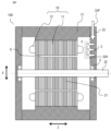
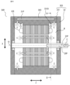
- FIG. 1 is a cross-sectional view of a rotating electrical machine 100 cut along a plane including a central axis O of a shaft 22, and shows a coolant flow path of a coolant C in the rotating electrical machine 100.
- the rotating electric machine 100 includes a housing 3, a stator 10, and a rotor 20.
- the housing 3 includes an annular housing cylindrical portion 31 and two housing end plates 32 that close openings on both sides of the housing cylindrical portion 31 in the axial direction Z.
- a stator 10 is fixed inside the housing cylindrical portion 31.
- the stator 10 is composed of a stator core 11 made of laminated electromagnetic steel plates, and a coil 12 wound around the stator core 11.
- the rotor 20 is disposed inside the stator 10.
- the rotor 20 is composed of a rotor core 21 made of laminated electromagnetic steel sheets, permanent magnets (not shown) housed in multiple permanent magnet insertion holes in the rotor core 21, and a shaft 22 that transmits rotational power.
- the rotor 20 is rotatably supported with its outer circumferential surface facing the inner circumferential surface of the stator 10 via bearings 5 fitted into the center of the two housing end plates 32 mentioned above.
- an inner rotor type is used in which the rotor 20 is arranged inside the stator 10, but it may also be an outer rotor type in which the rotor is arranged outside the stator, an axial gap type in which the stator and rotor face each other in the axial direction, or another type of arrangement.
- the cooling performance of a motor which is a type of rotating electrical machine, has a significant impact on its continuous operating performance and durability. For example, if the coil becomes hot due to copper loss during continuous operation, there is a concern that the coil may deteriorate. In particular, the coil ends exposed on the axial upper side of the stator core cannot dissipate heat to the stator core, so it is preferable to bring them into contact with a coolant to efficiently dissipate heat.
- the housing cylindrical portion 31 of the rotating electric machine 100 is provided with an internal housing flow path 31P (coolant flow path), and the cooling liquid C is diffused from the multiple injection holes 31H of the internal housing flow path 31P into the interior of the rotating electric machine 100 wider than the hole diameter of the injection holes 31H.
- the internal housing flow path 31P is provided with a characteristic configuration, for example, at the injection holes 31H and upstream thereof, which serves as a means for diffusing the cooling liquid C wider than the hole diameter of the injection holes 31H.
- the cooling liquid C floats at a high density in the space R within the housing where the coil ends 12E are exposed, so that the cooling liquid C adheres evenly to the surface of the coil ends 12E, enabling the coil ends 12E to be cooled uniformly.
- a rotor 20 is also provided with a rotor coolant flow path 20P as shown in Fig. 1.
- the rotor coolant flow path 20P consists of an inner-shaft flow path 22P formed hollow in the shaft 22, and an inner-rotor-core flow path 21P formed in the rotor core 21.
- end plates may be provided on both sides of the rotor core 21 in the axial direction Z, and part of the rotor coolant flow path 20P may be formed in the end plates themselves, or between the end plates and the laminated steel plates of the rotor core 21.
- the cooling liquid C used to cool the permanent magnets is sprayed from the spray holes 21H at the end of the rotor core 21 in the axial direction Z into the space R within the housing 3, the cooling liquid is spread wider than the hole diameter of the spray holes 21H, similar to the spray holes 31H of the housing cylindrical portion 31. This further increases the proportion of the cooling liquid C floating in the space R within the housing 3, improving the cooling effect of the coil ends 12E.
- a centrifugal spray method that uses the rotational force of the rotor has been proposed as a method for scattering coolant from the rotor toward the coil ends.
- the coolant flows down due to gravity instead of being sprayed, and therefore cannot be used to cool the coil ends.
- the coolant C sprayed from the rotor 20 can be made to float in the space R in the form of fine droplets regardless of the rotation speed, so that the coolant C can also be supplied to the coil ends 12E located vertically above and vertically to the side of the rotor 20.
- the proportion of cooling liquid C floating in the space R inside the housing 3 increases, which allows the cooling liquid C to adhere to and moisten the bearings 5 that are in the same space R.
- the cooling liquid C has properties as a lubricant for the bearings 5 and electrical insulation properties, it can function as an insulating coating that suppresses the occurrence of electrical corrosion in the bearings 5.
- the distribution of the amount of cooling liquid C supplied to the stator 10 and the amount of cooling liquid C supplied to the rotor 20 can be adjusted by changing the pressure loss by creating a difference in the inner diameter of the housing inner flow path 31P and the rotor cooling liquid flow path 20P.
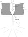
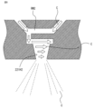
- FIG. 2 is a cross-sectional view of the injection hole 31H and the injection hole 21H.
- the hole diameters of the injection holes 31H, 21H provided at the outlets of the in-housing flow path 31P and the in-rotor core flow path 21P are smaller than the hole diameters of the in-housing flow path 31P and the in-rotor core flow path 21P. That is, the injection holes 31H, 21H have a tapered structure in which the hole diameter gradually becomes smaller toward the outlet, so that the pressure of the cooling liquid C after injection is lower than before injection, but the flow rate is faster.
- the cooling liquid C spreads over a range wider than the hole diameter of the injection holes 31H, 21H, and it becomes possible for the cooling liquid C to drift in the space R in the housing 3 shown in FIG. 1.
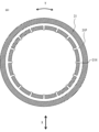
- FIG. 3 is a cross-sectional view of the housing cylindrical portion 31 cut perpendicularly to the axial direction Z, and is a cross-sectional view of a portion where the injection holes 31H are present.
- the housing cylindrical portion 31 has an internal housing flow passage 31P that is annular and extends around the entire circumference, and the internal housing flow passage 31P opens in the radial direction X toward the space R within the housing 3 and has a plurality of injection holes 31H that are spaced apart in the circumferential direction Y.
- multiple injection holes 31H are arranged to supply a sufficient amount of cooling liquid C.
- the injection holes 31H are evenly arranged in the circumferential direction Y in FIG. 3, they may be arranged unevenly as long as the amount of cooling liquid C supplied is sufficiently large.
- the cooling liquid C after injection floats within the space R, it is not necessary to arrange the injection holes 31H aimed at the coil end 12E.
- there is a high degree of freedom in the arrangement of the inner-housing flow path 31P and the injection holes 31H which reduces processing costs and makes it possible to miniaturize the motor 100 by saving space for the inner-housing flow path 31P.
- FIG. 4 is a cross-sectional view of a rotating electrical machine showing an example in which a housing end plate 32 is provided with an internal housing flow passage 32P.
- the internal flow passage 32P and the injection holes 32H may be provided in only one housing end plate 32 of the housing 3, so that the internal flow passage 32P may be short and simply designed.
- FIG. 5 is a cross-sectional view of the rotor 20 according to the first embodiment taken along a plane including the central axis O of the shaft 22.
- the rotor cooling liquid flow path 20P consists of an intra-shaft flow path 22P that extends in the axial direction Z from one end of the shaft 22 and further extends in the radial direction X and opens to the outside, a plurality of intra-end plate flow paths 23P that are connected to the intra-shaft flow path 22P and extend toward the outside in the radial direction X through an end plate 23 provided at one end of the rotor core 21 in the axial direction Z, and a plurality of intra-rotor core flow paths 21P that are connected to each of the intra-end plate flow paths 23P and extend in the axial direction Z along the permanent magnets M inside the rotor core 21.
- the outer end of the internal end plate flow path 23P is connected to an injection hole 21H1 that opens through the end plate 23 in the axial direction Z, and the other end in the axial direction Z of the internal rotor core flow path 21P is connected to an injection hole 21H2 that opens through the end plate 24.
- the cooling liquid C that flows in from the internal shaft flow path 22P is divided into a flow path that is injected from the injection hole 21H1 of one end plate 23 into the space R in the housing 3, and a flow path that flows in the axial direction Z along the side of the permanent magnet M and is then injected from the injection hole 21H2 provided in the opposite end plate 24 into the space R in the housing 3.
- the injection holes 21H1 and 21H2 provided on the end plates 23 and 24 have a tapered structure as shown in FIG. 2, so that the cooling liquid C can be injected in the form of fine droplets into the space R within the housing 3 even under driving conditions where the rotor 20 is not rotating.
- FIG. 6 is a cross-sectional view showing a modified example of the rotor cooling liquid flow path 20P.
- the inner-shaft flow passage 22P may be extended to the center of the rotor core 21 in the axial direction Z, and the inner-rotor-core flow passage 21P may be provided toward the outside in the radial direction X so as to connect to this, and may be provided so as to branch off to both sides in the axial direction Z along the permanent magnets M inside the permanent magnets M.
- the hole diameter of the inner-rotor-core flow passage 21P may be reduced in the laminated steel plates at both ends in the axial direction Z to form injection holes 21H, thereby increasing the flow rate of the coolant C after injection.
- the pressure of the cooling liquid C flowing through the rotor cooling liquid flow path 20P is kept high and the flow rate is kept fast.
- the rotor core 21 shown in Figures 5 and 6 can increase the airtightness of the cooling liquid flow path by filling the gaps (between the laminated magnetic steel sheets) with a resin such as an adhesive.
- a flow path is provided in the end plates 23, 24, it is also advisable to fill the gaps between the end plates 23, 24 and the laminated steel sheets with resin.
- the coolant C is a fluid that has electrical insulation and anti-rust properties (such as ATF: Automatic Transmission Fluid). If insulation around the coil 12 is ensured, a non-insulating fluid such as water can also be used, and a gas-liquid mixed phase refrigerant such as that used in air conditioners may also be used. If water or a refrigerant is used as the coolant C, when the coolant C comes into contact with the coil end 12E, heat is removed from the coil end 12E by the latent heat of vaporization due to the phase change from a liquid state to a gas state, which is expected to improve cooling efficiency.
- ATF Automatic Transmission Fluid
- the coolant C comes into contact with the heat-generating coil 12 and evaporates, the coolant C is prevented from accumulating in the gap G between the stator core 11 and the rotor core 21, as shown in FIG. 4, and a reduction in drag torque can also be expected.
- Housing and a stator including a stator core fixed to the housing and a coil wound around the stator core; a rotor having a rotor core and a shaft, the rotor being rotatably supported by the housing; At least one of the rotor and the housing is a cooling liquid flow path for supplying a cooling liquid to a coil end of the coil; The hole diameter of the injection hole for injecting the cooling liquid from the cooling liquid flow path into the space in the housing is smaller than the diameter of the cooling liquid flow path.
- the cooling liquid By spraying the cooling liquid in a mist form that floats under gravity, the cooling liquid can be sprayed in all directions even when the rotor is rotating at a low speed, allowing the coil ends to be cooled uniformly. Also, Since the injection hole has a tapered shape, Because the area near the outlet of the coolant flow path is small, the flow speed of the sprayed coolant becomes fast and draws in the surrounding air with great force, allowing the coolant to be spread over an area wider than the diameter of the spray hole. Also, The rotor core of the rotor includes an internal flow passage through which the coolant flows along the permanent magnets housed in the rotor core. The cooling fluid that dissipates the heat generated by the permanent magnets can be reused to cool the coils.
- the rotor core is made of a plurality of laminated steel plates or a plurality of laminated steel plates and end plates, Since the spaces between the laminated steel plates and between the laminated steel plates and the end plates are filled with resin, The coolant flow path in the rotor is sealed, and the coolant can be kept at a high flow rate and high pressure all the way to the injection holes.
- Embodiment 2 The rotating electric machine according to the second embodiment will be described below, focusing on the differences from the first embodiment.
- an injection hole structure that improves cooling effect and productivity is described as an alternative configuration for diffusing the cooling liquid C wider than the diameter of the cooling liquid flow path described in embodiment 1.
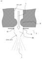
- FIG. 7 is a cross-sectional view of the injection holes 231H and 221H.
- the inner-housing flow path 31P and the inner-rotor-core flow path 21P have an orifice OF, an intake port IN, and a mixing chamber RM located upstream of the injection holes 231H, 221H.
- the orifice OF is located upstream of the injection holes 231H, 221H and has an inner diameter smaller than the inner diameters of the inner-housing flow path 31P and the inner-rotor-core flow path 21P (cooling liquid flow path).
- the orifice OF has a high flow rate and a low pressure. Taking advantage of this, the hole diameter of the orifice OF is set so that the pressure in the mixing chamber RM becomes lower than the air pressure of the gas in the housing 3 (atmospheric pressure).
- the injection holes 231H and 221H shown in FIG. 7 make it easier for the cooling liquid C to spread wider than the hole diameter of the injection holes 231H and 221H. Therefore, the droplets can be dispersed as an even finer mist.
- FIG 8 is a cross-sectional view of the injection hole 221H2 in a modified example of the second embodiment.
- a swirl chamber RM2 is provided in front of the injection hole 221H2 in the rotor core inner flow path 21P (as well as the other coolant flow paths). Inside the swirl chamber RM2, the coolant C flows in a spiral pattern along the inner wall of the swirl chamber RM2, so that the coolant C is widely dispersed in the space R within the housing 3, spreading out from the injection hole 221H2.
- Figure 9 is a cross-sectional view of a nozzle part PA having an injection hole 221H3 according to a modified example of the second embodiment.
- the tip of the coolant flow path is divided into the nozzle part PA, which has each injection hole shown in Figures 2, 7, and 8, and a threaded portion S2 for connecting to a threaded portion S1 provided on the rotor core 21 or the housing end plate 32. This makes it easier to mold the nozzle part PA by die-cutting, which is expected to improve mass productivity.
- the nozzle part PA shown in FIG. 9 may be the nozzle of a spray device (sprayer).
- the nozzle part may be of any shape as long as it has the function of spraying the cooling liquid C in a mist, and it is also possible to configure the nozzle part so that it is equipped with a variety of sprayers (the spraying principle may be a spray nozzle type, electrostatic nozzle type, ultrasonic spray type, etc.) with a spraying function at the tip of the cooling liquid flow path.
- tapered structure shown in FIG. 2 described in the first embodiment and in FIGS. 7 to 9 in the second embodiment is a linear taper, but it may be a curved taper or a stepped structure that combines different hole diameters.
- the cooling liquid flow path includes an orifice in front of the injection hole where the inner diameter of the cooling liquid flow path is smaller than the inner diameter of the front and rear of the injection hole, an intake port that draws in gas from the space, and a mixing chamber that mixes the cooling liquid and the gas.
- the cooling liquid passing through the orifice flows at a high speed and its pressure is reduced, making it possible to make the air pressure in the mixing chamber lower than atmospheric pressure.
- the cooling liquid flow path includes a swirl chamber that generates a swirling flow along an inner wall, located before the injection hole.
- the cooling liquid that flows into the swirl chamber flows in a spiral pattern along the inner wall of the swirl chamber, and the cooling liquid can be sprayed into the space within the housing so that it spreads from the injection holes. Also, Since the injection hole is a nozzle of a spray device, A spray device can be used to distribute the coolant in a finer mist to ensure even cooling within the housing.
- FIG. 11 is a cross-sectional view taken along line DD in FIG. 10, showing a cross section of only the housing cylindrical portion 331 and the coil end 12E.
- a protrusion 331D is provided on the inner wall of the housing cylindrical portion 331, vertically above the coil end 12E when the rotating electric machine 300 is in an operating state, protruding vertically downward.
- the flow passage 31P inside the housing on the outside of the protrusion 331D in the radial direction X, the temperature of the inner wall surface of the housing 303 near the protrusion 331D is reduced. Therefore, when water or a refrigerant is used as the coolant C, the phase-changed gas is more likely to condense than on other inner wall surfaces, and the amount of coolant C dripping onto the coil end 12E can be increased.
- the amount of coolant C dripping onto the coil end 12E can be increased by guiding the coolant C to the protruding portion 331D by inclining the inner wall of the housing cylindrical portion 331 toward the protruding portion 331D or by providing a thin groove therein through capillary action.
- FIG. 12 shows a modified example of the housing cylindrical portion 331 and corresponds to FIG.
- protrusions 331D2 and 331D3 are also disposed at the 2 o'clock and 10 o'clock directions, respectively, for the coil end 12E.
- the coolant C that flows down along the annular inner wall surface of the housing cylindrical portion 331 can be collected by the protrusions 331D1 to 331D3, thereby increasing the amount of dripping onto the coil end 12E.
- an additional cooling effect can be provided uniformly in the circumferential direction Y.
- FIG. 13 is a cross-sectional view showing a modified example of the housing cylindrical portion 331 and the protruding portion 331D, and is a partial cross-sectional view perpendicular to the axial direction Z.
- the housing cylindrical portion 331 is molded by die casting, there is a problem that the provision of a protruding portion, which is a portion with a different thickness, may result in internal voids and a decrease in strength. Therefore, the decrease in strength can be avoided by molding the housing cylindrical portion 331 and the protruding portion 331D separately, and then, for example, as shown in FIG. 13, by using a slit SL provided in the housing cylindrical portion 331 to insert the protruding portion 331D from the axial direction Z and attaching it later.
- the above description of the protruding portion 331D does not limit the shape, position, or number of protruding portions, and may be freely changed as necessary.
- the inner wall of the housing has a protruding portion that protrudes vertically downward above the coil end in an operating state
- the liquid droplets collect on protrusions located directly above the coil ends, and can be dripped onto the coil ends to provide additional cooling.
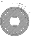
- FIG. 14 is a plan view of an end plate 423 of a rotor 20 according to the fourth embodiment, as viewed from the outside in the axial direction Z.
- FIG. 15 is a cross-sectional view perpendicular to the axial direction Z of rotor core 21 and permanent magnets M according to this embodiment.
- FIG. 16 is a cross-sectional view of a hollow flow passage portion of a shaft 422 and a main portion of an end plate 423 according to the fourth embodiment, in which the shaft 422 and the end plate 423 are cut along a plane including the central axis O of the shaft 422.
- FIG. 17 is a cross-sectional view taken along line E--E of FIG.
- the flow rate of the coolant to the injection holes and the coolant flow passages according to the rotor speed can be adjusted by using electrical control or structural features.
- the end plate 423 is provided with both injection holes 21H with a small hole diameter as shown in Figures 2 and 7 to 9, and injection holes 421H with a larger hole diameter than injection holes 21H that do not have a tapered structure.
- the cooling liquid C is mainly sprayed from injection holes 21H with a small hole diameter
- the cooling liquid C is mainly sprayed from injection holes 421H with a large hole diameter.
- injection holes 421H may have a slightly tapered shape as long as their hole diameter is larger than injection holes 21H.
- the rotor core internal flow passages 21P are provided in the axial direction Z along the permanent magnet M on both sides of the circumferential direction Y, and are connected to the injection holes 21H of the end plate 423 described in FIG. 14.
- the rotor core internal flow passages 421P are provided in the axial direction Z along the permanent magnet M at the center of the circumferential direction Y and inside the radial direction X, and are connected to the injection holes 421H.
- the shaft inner flow passage 422P extending in the axial direction Z from one end of the shaft 422 is provided with a cylindrical branch pipe 422Q at the end opposite the inlet of the shaft inner flow passage 422P, which has the same axis as the central axis O of the shaft inner flow passage 422P and has a first flow passage opening IN1 with a smaller diameter than the shaft inner flow passage 422P.
- the first flow passage port IN1 which is the inlet of the branch pipe 422Q, is connected to a plurality of first end plate internal flow passages 423P1 extending radially outward in the end plate 423, and each of these is further connected to the rotor core internal flow passage 21P (first coolant flow passage system).
- the second flow passage port IN2 formed between the outer peripheral surface of the branch pipe 422Q and the inner peripheral surface of the shaft internal flow passage 422P is connected to a plurality of second end plate internal flow passages 423P2 extending radially outward in the end plate 423, and each of these is further connected to the rotor core internal flow passage 421P (second coolant flow passage system).
- the cross-sectional area of the first flow passage port IN1 cut perpendicular to the axial direction Z is sufficiently larger than the cross-sectional area of the second flow passage port IN2 cut perpendicular to the axial direction Z.
- each injection hole provided in the end plate 423 connected to the shaft internal flow path 422P may be made smaller than the diameter of each injection hole provided in the end plate on the opposite side in the axial direction Z, so that the amount of cooling liquid C sprayed from both end plates is equal.
- first end plate internal flow passages 423P1 and second end plate internal flow passages 423P2 may be reduced by connecting multiple end plate internal flow passages in the circumferential direction inside the end plate.
- the rotor includes a plurality of coolant flow passage systems each including the coolant flow passage, and the flow rate of the coolant flowing through each coolant flow passage system can be adjusted according to the rotation speed of the rotor. A constant amount of cooling liquid can be supplied to the space within the housing regardless of the rotation speed.
- the shaft of the rotor includes a shaft passage extending axially through the shaft from one end side of the shaft, the shaft flow path includes a branch pipe at an end opposite to an inlet of the shaft flow path, the branch pipe having a first flow path port having the same axis as an axis of the shaft flow path and a smaller diameter than the shaft flow path, the first flow passage port is connected to a first coolant flow passage system which is one of the plurality of coolant flow passage systems; A second flow passage port formed between an outer circumferential surface of the branch pipe and an inner circumferential surface of the shaft inner flow passage is connected to a second coolant flow passage system which is one of the plurality of coolant flow passage systems.
- the inner-shaft flow passage 422P of the shaft 422 is filled with the coolant, and a large amount of the coolant C flows into the first coolant flow passage system through the first flow passage port IN1 in accordance with the cross-sectional area ratio of the first flow passage port IN1 to the second flow passage port IN2.
- the coolant C flows in a circular shape that sticks to the inner wall of the inner-shaft flow passage 422P due to centrifugal force, and a large amount of the coolant C flows into the second coolant flow passage system from the second flow passage port IN2 on the outer periphery.
- Embodiment 5 An electric vehicle according to the fifth embodiment will be described below.
- the configuration has been described in which the space R within the housing of the rotating electrical machine is filled with the sprayed coolant C to uniformly cool the coil ends 12E.
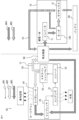
- FIG. 18 is a block diagram showing an example of a cooling circuit of the electric vehicle 50.
- An arrow AR1 in FIG. 18 indicates a flow path of the liquid refrigerant C1.
- An arrow AR2 in FIG. 18 indicates a flow path of the gas-liquid mixed phase and low-temperature refrigerant C1.
- An arrow AR3 in FIG. 18 indicates a flow path of the gas-liquid mixed phase and high temperature refrigerant C1.
- the refrigerant C1 of the car air conditioner CA circulates through a condenser 51 , a receiver 52 , an expansion valve 53 , an evaporator 54 , and a compressor 55 , and then returns to the condenser 51 .
- a portion of the low-temperature, low-pressure gas-liquid mixed-phase refrigerant C1 sprayed from the expansion valve 53 of the car air conditioner CA is supplied to the inverter 71 and the battery 80, dissipating heat generated by each.
- the refrigerant C1 that passes through the inverter 71 is thought to warm up to about 60°C to 80°C, but it is thought that a sufficient cooling effect is obtained for the coil 12 and permanent magnets M, which reach temperatures of 100°C or higher inside the motor 100.
- the temperature of the refrigerant C1 (cooling liquid C) increases in this order from the upstream side to the downstream side.
- the gas-liquid mixed phase refrigerant C1 supplied to the motor 100 is widely dispersed within the housing 3 of the motor 100 from each of the injection holes 21H, 31H having the tip structure shown in Figures 2, 7 to 9, and floats at high density in the internal space R, so that it comes into contact with the coil ends 12E evenly, providing a uniform cooling effect.
- the gas-liquid mixed phase refrigerant C1 when the gas-liquid mixed phase refrigerant C1 is sprayed into the space R inside the housing 3 of the motor 100, it is easier to form finer droplets than a single-phase liquid.
- the heat generated at the coil end 12E causes a portion of the refrigerant C1 to change phase from a liquid state to a gas state, which is expected to have a significant heat removal effect due to the latent heat of evaporation.
- the refrigerant that has become a high-temperature gas-liquid two-phase state inside the motor 100 is then supplied to the gear box 72, where it functions as a gear lubricant.
- the refrigerant C1 is supplied to the compressor 55 and returned to the circulation system of the car air conditioner CA.
- FIG. 19 is a block diagram showing another example of the cooling circuit of the electric vehicle 50 according to a modification of the fifth embodiment.
- An arrow AR4 in FIG. 19 indicates a flow path of the low-temperature refrigerant C2.
- An arrow AR5 in FIG. 19 indicates a flow path of the high-temperature refrigerant C2.
- the refrigerant C2 used for the motor 100, inverter 71, and battery 80 is preferably rust-resistant and insulating, and a specific example is cooling oil such as ATF. Therefore, two types of refrigerant are used, refrigerant C1 for the car air conditioner CA and refrigerant C2 for driving, and the refrigerant C2 is cooled by the refrigerant C1 in the heat exchanger 60.
- the drive side shares one type of refrigerant C2, which allows for a reduction in the number of parts such as the liquid delivery pump, exchanger, and refrigerant storage tank, making it possible to reduce costs and weight.
- refrigerant C2 which allows for a reduction in the number of parts such as the liquid delivery pump, exchanger, and refrigerant storage tank, making it possible to reduce costs and weight.
- the motor 100, inverter 71, and gear box 72 are integrated into a single casing 70, and by sharing the refrigerant C2, the refrigerant flow path provided in the casing 70 can be simplified.
- each component in the electric vehicle 50 for example, the refrigerant C1 for the car air conditioner CA and the refrigerant C2 that cools the motor 100, inverter 71, and battery 80 that make up the vehicle drive system, via the heat exchanger 60, even if the refrigerant itself is not shared, it is possible to mutually use the cooling circuits made up of each refrigerant, select the optimal type of refrigerant for each component in the entire electric vehicle 50, and build a cooling mechanism that allows heat transfer as a whole, thereby optimizing the cooling mechanism to a high level.
- a relatively low-temperature refrigerant is used as the refrigerant C1 for the car air conditioner CA in the electric vehicle 50 as the flow path of the cooling circuit, and the refrigerant C2 used to cool the inverter 71 is used to cool the motor 100 and the gear box 72, with the temperature increasing relatively toward the downstream side.
- the motor applied to this embodiment is a combination of a rotating electric machine equipped with a refrigerant diffusion means in the refrigerant flow path described in the first to fourth embodiments, and the refrigerant used to cool the rotating electric machine is used in conjunction with a cooling circuit that cools and lubricates each component in the electric vehicle, reducing the number of parts in the entire electric vehicle and realizing a cooling system that optimizes the cooling mechanism.
- this is not necessarily intended to be applied only to rotating electric machines equipped with a refrigerant diffusion means, and may be combined with a general rotating electric machine that uses a refrigerant to cool the rotating electric machine.
- the cooling system includes a refrigerant circulation system that uses at least a part of the cooling liquid of the rotating electrical machine as a refrigerant, By supplying a portion of the coolant for the rotating electric machine to other components installed inside the vehicle, the coolant pump, heat exchanger, coolant storage tank, etc. can be shared among multiple components, making it possible to reduce the cost and weight of electric vehicles.
- an inverter, a battery, and a gear that drive the rotating electric machine is used as a refrigerant for at least one of cooling the inverter, cooling the battery, and lubricating the gears,
- Rotating electric machines, inverters, batteries, and gears are often located close to each other, so by standardizing the system that supplies coolant to them, it is possible to reduce the number of parts. It is also effective for electromechanical integration (ELECTRIC AXLE) that combines motors, inverters, and gears in a single casing.
- ELECTRIC AXLE electromechanical integration
- the refrigerant for the car air conditioner is used as the cooling liquid for the rotating electrical machine.
- the gas-liquid mixed-phase refrigerants used in air conditioners have a large heat removal effect due to the latent heat of evaporation caused by the phase change from liquid to gas, making them excellent as motor coolants.
- a rotating electric machine a refrigerant circulation system that utilizes at least a portion of the cooling liquid
- a refrigerant for a car air conditioner constituting the refrigerant circulation system a refrigerant for cooling an inverter that drives and controls the rotating electric machine
- the cooling liquid for the rotating electric machine The refrigerant and the cooling liquid circulate in this order from the upstream side to the downstream side, and the temperatures of the refrigerant and the cooling liquid become higher in the order from the upstream side to the downstream side. It is possible to obtain an electric vehicle that can efficiently perform cooling by systematizing suitable cooling for the temperature of each component that needs to be cooled throughout the vehicle.
- a cooling circuit containing the refrigerant for the car air conditioner The cooling circuit for cooling the inverter that drives and controls the rotating electric machine is It is equipped with a refrigerant circulation system that can transfer heat through a heat exchanger, While selecting the optimal type of refrigerant for each component within an electric vehicle, it is possible to construct a cooling mechanism that enables heat transfer as a whole, thereby optimizing the cooling mechanism of the electric vehicle at a high level.
Landscapes
- Engineering & Computer Science (AREA)
- Power Engineering (AREA)
- Motor Or Generator Cooling System (AREA)
Priority Applications (2)
| Application Number | Priority Date | Filing Date | Title |
|---|---|---|---|
| PCT/JP2023/042844 WO2025115159A1 (ja) | 2023-11-30 | 2023-11-30 | 回転電機及び電動車両 |
| JP2025560464A JPWO2025115159A1 (https=) | 2023-11-30 | 2023-11-30 |
Applications Claiming Priority (1)
| Application Number | Priority Date | Filing Date | Title |
|---|---|---|---|
| PCT/JP2023/042844 WO2025115159A1 (ja) | 2023-11-30 | 2023-11-30 | 回転電機及び電動車両 |
Publications (1)
| Publication Number | Publication Date |
|---|---|
| WO2025115159A1 true WO2025115159A1 (ja) | 2025-06-05 |
Family
ID=95896580
Family Applications (1)
| Application Number | Title | Priority Date | Filing Date |
|---|---|---|---|
| PCT/JP2023/042844 Pending WO2025115159A1 (ja) | 2023-11-30 | 2023-11-30 | 回転電機及び電動車両 |
Country Status (2)
| Country | Link |
|---|---|
| JP (1) | JPWO2025115159A1 (https=) |
| WO (1) | WO2025115159A1 (https=) |
Citations (7)
| Publication number | Priority date | Publication date | Assignee | Title |
|---|---|---|---|---|
| JPS54607U (https=) * | 1970-09-10 | 1979-01-05 | ||
| JPH10336968A (ja) * | 1997-05-29 | 1998-12-18 | Denso Corp | 車両用回転電機 |
| JP2005012890A (ja) * | 2003-06-18 | 2005-01-13 | Toyota Motor Corp | 駆動システムおよびそれを搭載した自動車 |
| JP2005131486A (ja) * | 2003-10-29 | 2005-05-26 | Kyoritsu Gokin Co Ltd | 噴霧ノズルおよび噴霧方法 |
| WO2007094350A1 (ja) * | 2006-02-16 | 2007-08-23 | Mitsubishi Electric Corporation | 回転電機の冷却構造 |
| JP2016154418A (ja) * | 2015-02-20 | 2016-08-25 | 株式会社安川電機 | 駆動装置、インバータ取り外し方法及びインバータ取り付け方法 |
| JP2019165587A (ja) * | 2018-03-20 | 2019-09-26 | 本田技研工業株式会社 | 回転電機 |
-
2023
- 2023-11-30 JP JP2025560464A patent/JPWO2025115159A1/ja active Pending
- 2023-11-30 WO PCT/JP2023/042844 patent/WO2025115159A1/ja active Pending
Patent Citations (7)
| Publication number | Priority date | Publication date | Assignee | Title |
|---|---|---|---|---|
| JPS54607U (https=) * | 1970-09-10 | 1979-01-05 | ||
| JPH10336968A (ja) * | 1997-05-29 | 1998-12-18 | Denso Corp | 車両用回転電機 |
| JP2005012890A (ja) * | 2003-06-18 | 2005-01-13 | Toyota Motor Corp | 駆動システムおよびそれを搭載した自動車 |
| JP2005131486A (ja) * | 2003-10-29 | 2005-05-26 | Kyoritsu Gokin Co Ltd | 噴霧ノズルおよび噴霧方法 |
| WO2007094350A1 (ja) * | 2006-02-16 | 2007-08-23 | Mitsubishi Electric Corporation | 回転電機の冷却構造 |
| JP2016154418A (ja) * | 2015-02-20 | 2016-08-25 | 株式会社安川電機 | 駆動装置、インバータ取り外し方法及びインバータ取り付け方法 |
| JP2019165587A (ja) * | 2018-03-20 | 2019-09-26 | 本田技研工業株式会社 | 回転電機 |
Also Published As
| Publication number | Publication date |
|---|---|
| JPWO2025115159A1 (https=) | 2025-06-05 |
Similar Documents
| Publication | Publication Date | Title |
|---|---|---|
| EP2736152B1 (en) | Electric motor and turbo compressor | |
| US20230107455A1 (en) | Motor, motor cooling system, and electric vehicle | |
| US12160159B2 (en) | Cooling a rotating electrical machine | |
| EP2724450B1 (en) | Cooling structure of rotary electric machine | |
| KR20090048028A (ko) | 하이브리드 차량용 모터 냉각 장치 및 방법 | |
| JP2025076507A (ja) | モータユニット | |
| CN115139771B (zh) | 电机系统及具有该电机系统的车辆 | |
| CN111313608B (zh) | 一种带油路结构的油冷电机、电机油路冷却系统 | |
| JP2014045586A (ja) | 回転電機 | |
| WO2025115159A1 (ja) | 回転電機及び電動車両 | |
| CN120855757B (zh) | 一种具有自稳定功能的航空用发电机 | |
| JP6189070B2 (ja) | 回転電機 | |
| JP7732515B2 (ja) | 回転電機 | |
| CN118386810B (zh) | 电动总成和车辆 | |
| CN222706365U (zh) | 电机的冷却结构 | |
| CN112177948B (zh) | 冷却效果好的压缩机结构及磁悬浮压缩机 | |
| CN222016343U (zh) | 喷淋环、电机、驱动总成以及车辆 | |
| CN220036777U (zh) | 一种增压器润滑系统 | |
| CN118054599A (zh) | 电机、电驱动总成系统、车辆以及用于冷却电机的方法 | |
| CN221354063U (zh) | 一种集成式油水复合冷却电机结构 | |
| CN224068498U (zh) | 定子、电机以及车辆 | |
| TWI888018B (zh) | 旋轉電機、及使用旋轉電機之空氣壓縮機 | |
| CN222735895U (zh) | 一种油冷发电机及汽车 | |
| US20250290540A1 (en) | Rotary shaft device with integrated cooling and lubrication | |
| CN120667369A (zh) | 电动泵壳体、电动泵、液压供能装置、底盘系统及车辆 |
Legal Events
| Date | Code | Title | Description |
|---|---|---|---|
| 121 | Ep: the epo has been informed by wipo that ep was designated in this application |
Ref document number: 23960177 Country of ref document: EP Kind code of ref document: A1 |
|
| ENP | Entry into the national phase |
Ref document number: 2025560464 Country of ref document: JP Kind code of ref document: A |