WO2025105134A1 - 燃焼システム - Google Patents
燃焼システム Download PDFInfo
- Publication number
- WO2025105134A1 WO2025105134A1 PCT/JP2024/037737 JP2024037737W WO2025105134A1 WO 2025105134 A1 WO2025105134 A1 WO 2025105134A1 JP 2024037737 W JP2024037737 W JP 2024037737W WO 2025105134 A1 WO2025105134 A1 WO 2025105134A1
- Authority
- WO
- WIPO (PCT)
- Prior art keywords
- ammonia
- flow path
- temperature
- injector
- pressure
- Prior art date
- Legal status (The legal status is an assumption and is not a legal conclusion. Google has not performed a legal analysis and makes no representation as to the accuracy of the status listed.)
- Pending
Links
Images





Classifications
-
- F—MECHANICAL ENGINEERING; LIGHTING; HEATING; WEAPONS; BLASTING
- F02—COMBUSTION ENGINES; HOT-GAS OR COMBUSTION-PRODUCT ENGINE PLANTS
- F02C—GAS-TURBINE PLANTS; AIR INTAKES FOR JET-PROPULSION PLANTS; CONTROLLING FUEL SUPPLY IN AIR-BREATHING JET-PROPULSION PLANTS
- F02C3/00—Gas-turbine plants characterised by the use of combustion products as the working fluid
- F02C3/20—Gas-turbine plants characterised by the use of combustion products as the working fluid using a special fuel, oxidant, or dilution fluid to generate the combustion products
- F02C3/24—Gas-turbine plants characterised by the use of combustion products as the working fluid using a special fuel, oxidant, or dilution fluid to generate the combustion products the fuel or oxidant being liquid at standard temperature and pressure
-
- F—MECHANICAL ENGINEERING; LIGHTING; HEATING; WEAPONS; BLASTING
- F02—COMBUSTION ENGINES; HOT-GAS OR COMBUSTION-PRODUCT ENGINE PLANTS
- F02C—GAS-TURBINE PLANTS; AIR INTAKES FOR JET-PROPULSION PLANTS; CONTROLLING FUEL SUPPLY IN AIR-BREATHING JET-PROPULSION PLANTS
- F02C7/00—Features, components parts, details or accessories, not provided for in, or of interest apart form groups F02C1/00 - F02C6/00; Air intakes for jet-propulsion plants
- F02C7/22—Fuel supply systems
- F02C7/224—Heating fuel before feeding to the burner
-
- F—MECHANICAL ENGINEERING; LIGHTING; HEATING; WEAPONS; BLASTING
- F02—COMBUSTION ENGINES; HOT-GAS OR COMBUSTION-PRODUCT ENGINE PLANTS
- F02C—GAS-TURBINE PLANTS; AIR INTAKES FOR JET-PROPULSION PLANTS; CONTROLLING FUEL SUPPLY IN AIR-BREATHING JET-PROPULSION PLANTS
- F02C9/00—Controlling gas-turbine plants; Controlling fuel supply in air- breathing jet-propulsion plants
- F02C9/26—Control of fuel supply
- F02C9/40—Control of fuel supply specially adapted to the use of a special fuel or a plurality of fuels
-
- F—MECHANICAL ENGINEERING; LIGHTING; HEATING; WEAPONS; BLASTING
- F23—COMBUSTION APPARATUS; COMBUSTION PROCESSES
- F23K—FEEDING FUEL TO COMBUSTION APPARATUS
- F23K5/00—Feeding or distributing other fuel to combustion apparatus
- F23K5/02—Liquid fuel
- F23K5/14—Details thereof
- F23K5/20—Preheating devices
-
- F—MECHANICAL ENGINEERING; LIGHTING; HEATING; WEAPONS; BLASTING
- F23—COMBUSTION APPARATUS; COMBUSTION PROCESSES
- F23R—GENERATING COMBUSTION PRODUCTS OF HIGH PRESSURE OR HIGH VELOCITY, e.g. GAS-TURBINE COMBUSTION CHAMBERS
- F23R3/00—Continuous combustion chambers using liquid or gaseous fuel
-
- F—MECHANICAL ENGINEERING; LIGHTING; HEATING; WEAPONS; BLASTING
- F23—COMBUSTION APPARATUS; COMBUSTION PROCESSES
- F23R—GENERATING COMBUSTION PRODUCTS OF HIGH PRESSURE OR HIGH VELOCITY, e.g. GAS-TURBINE COMBUSTION CHAMBERS
- F23R3/00—Continuous combustion chambers using liquid or gaseous fuel
- F23R3/28—Continuous combustion chambers using liquid or gaseous fuel characterised by the fuel supply
Definitions
- Gas turbine systems and the like are used as combustion systems for burning fuel in a combustor.
- ammonia may be used as fuel, as disclosed in Patent Document 1, for example. By using ammonia as fuel, carbon dioxide emissions are suppressed.
- One type of combustion system is one that supplies liquid ammonia to the combustion chamber without vaporizing it.
- This type of combustion system offers various benefits, such as reduced equipment costs by eliminating the need for a vaporizer.
- the objective of this disclosure is to provide a combustion system that can improve the efficiency of the combustion system.
- the combustion system disclosed herein includes a combustor having an ammonia tank in which ammonia is stored in a liquid state, a combustion chamber, and an injector facing the combustion chamber, the injector being connected to the ammonia tank via an ammonia flow path, and ammonia being supplied in a liquid state to the injector; a temperature adjustment device that adjusts the temperature of the ammonia supplied to the injector; and a control device that controls the temperature adjustment device based on information regarding the pressure of ammonia in the injector so that the temperature of the ammonia supplied to the injector is equal to or lower than the saturation temperature of ammonia in the injector.
- the flow paths include a first flow path and a second flow path that merge at a junction upstream of the injection valve, and the temperature of the ammonia flowing into the junction from the first flow path and the temperature of the ammonia flowing into the junction from the second flow path are different from each other, and the temperature adjustment device may include a flow rate ratio adjustment device that adjusts the flow rate ratio, which is the ratio between the flow rate of ammonia flowing into the junction from the first flow path and the flow rate of ammonia flowing into the junction from the second flow path.
- the temperature adjustment device may include a preheater that preheats the ammonia flowing through one of the first flow path and the second flow path.
- the temperature adjustment device may include a first preheater that preheats the ammonia flowing through the first flow path, and a second preheater that preheats the ammonia flowing through the second flow path.
- the flow path may not have a junction upstream of the injection valve, and the temperature adjustment device may include a preheater that preheats the ammonia flowing through the flow path.
- the information may include parameters that affect the pressure, and the control device may use a map showing the correspondence between the parameters and the saturation temperature to identify the saturation temperature based on the parameters, and control the temperature adjustment device based on the identified saturation temperature.
- the information may include parameters that affect the pressure, and the control device may use a map showing the correspondence between the parameters and the control targets of the temperature adjustment device to identify the control target based on the parameters, and control the temperature adjustment device based on the identified control target.
- the information may include parameters that affect the pressure, and the control device may calculate the pressure based on the parameters and control the temperature adjustment device based on the calculated pressure.
- the information may include pressure measurements, and the controller may control the temperature adjustment device based on the measurements.
- This disclosure makes it possible to improve the efficiency of the combustion system.
- FIG. 1 is a schematic diagram showing a configuration of a combustion system according to an embodiment of the present disclosure.
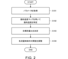
- FIG. 2 is a flowchart illustrating a first example of a flow of a process performed by the control device according to the embodiment of the present disclosure.
- FIG. 3 is a flowchart illustrating a second example of the flow of processing performed by the control device according to the embodiment of the present disclosure.
- FIG. 4 is a flowchart illustrating a third example of the flow of a process performed by the control device according to the embodiment of the present disclosure.
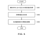
- FIG. 5 is a flowchart illustrating a fourth example of the flow of a process performed by the control device according to the embodiment of the present disclosure.
- FIG. 1 is a schematic diagram showing a configuration of a combustion system according to an embodiment of the present disclosure.
- FIG. 2 is a flowchart illustrating a first example of a flow of a process performed by the control device according to the embodiment of the present disclosure.
- FIG. 3 is a flowchar
- FIG. 6 is a schematic diagram showing the configuration of a combustion system according to a first modified example.
- FIG. 7 is a schematic diagram showing the configuration of a combustion system according to a second modified example.
- FIG. 8 is a schematic diagram showing the configuration of a combustion system according to a third modified example.
- FIG. 1 is a schematic diagram showing the configuration of a combustion system 1 according to this embodiment.
- the combustion system 1 is a gas turbine system that obtains power from combustion gas. As shown in FIG. 1, the combustion system 1 includes a compressor 11, a turbine 12, a combustor 13, an ammonia tank 14, a pump 15, a control device 16, and a temperature adjustment device 100.
- the compressor 11 and the turbine 12 rotate as a unit.
- the compressor 11 and the turbine 12 are connected to each other by a shaft.
- the compressor 11 is provided in the intake air flow path L1, which is connected to the combustor 13. Air to be supplied to the combustor 13 flows through the intake air flow path L1. An intake port (not shown) through which air is taken in from the outside is provided at the upstream end of the intake air flow path L1. The air taken in from the intake port passes through the compressor 11 and is sent to the combustor 13. The compressor 11 compresses the air and discharges it downstream.
- the turbine 12 is provided in the exhaust flow path L2 that is connected to the combustor 13. Exhaust gas discharged from the combustor 13 flows through the exhaust flow path L2. The exhaust gas discharged from the combustor 13 passes through the turbine 12 and is sent to the downstream side of the turbine 12 in the exhaust flow path L2. The turbine 12 generates rotational power by being rotated by the exhaust gas.
- a generator (not shown) is connected to the shaft connecting the compressor 11 and the turbine 12. The rotational power transmitted from the turbine 12 to the shaft is used to generate electricity by the generator.
- Air compressed by the compressor 11 is supplied to the combustor 13 through the intake passage L1, and ammonia is supplied in liquid form as fuel.
- combustion is carried out using ammonia as fuel.
- Exhaust gas generated in the combustor 13 is discharged to the exhaust passage L2.
- the combustor 13 has a combustion chamber 13a and an injection valve 13b.
- Ammonia which is a fuel
- the injection valve 13b injects the ammonia, which is a fuel, into the combustion chamber 13a.
- the injection valve 13b has an injection port 13b1. Ammonia is injected from the injection port 13b1.
- the injection valve 13b faces the combustion chamber 13a.
- the injection port 13b1 of the injection valve 13b faces the combustion chamber 13a.
- the injection valve 13b is connected to the ammonia tank 14 via an ammonia flow path L3. Ammonia is supplied in liquid form from the ammonia tank 14 to the injection valve 13b.
- Ammonia is stored in liquid form in the ammonia tank 14.
- the ammonia is maintained in liquid form, for example, at atmospheric pressure and -33°C.
- the ammonia tank 14 is connected to the injector 13b of the combustor 13 via the ammonia flow path L3.
- Ammonia flows in liquid form through flow path L3.
- a pump 15 is provided on the downstream side of the ammonia tank 14 in flow path L3. The pump 15 sends the ammonia supplied from the ammonia tank 14 to the downstream side.
- Flow path L3 branches into a first flow path L3a and a second flow path L3b at a branching point P1 downstream of the ammonia tank 14, and merges at a junction P2 upstream of the injector 13b.
- flow path L3 includes a first flow path L3a and a second flow path L3b that merge at a junction P2 upstream of the injector 13b.
- Ammonia that has passed through the pump 15 is sent to the first flow path L3a and the second flow path L3b, respectively, at the branching point P1.
- the combustion system 1 is provided with a temperature adjustment device 100 that adjusts the temperature of the ammonia supplied to the injector 13b.
- the temperature adjustment device 100 includes a flow rate ratio adjustment device 110 and a preheater 120.
- the flow rate ratio adjustment device 110 adjusts the flow rate ratio, which is the ratio between the flow rate of the ammonia flowing from the first flow path L3a to the junction P2 and the flow rate of the ammonia flowing from the second flow path L3b to the junction P2.
- the preheater 120 can make the temperature of the ammonia flowing from the first flow path L3a to the junction P2 different from the temperature of the ammonia flowing from the second flow path L3b to the junction P2. Therefore, the flow rate ratio adjustment device 110 and the preheater 120 realize the function of adjusting the temperature of the ammonia supplied to the injector 13b.
- the flow rate ratio adjustment device 110 includes a first flow rate control valve 111 and a second flow rate control valve 112.
- the first flow control valve 111 is provided in the first flow path L3a.
- the first flow control valve 111 adjusts the flow rate of ammonia flowing from the first flow path L3a to the junction P2 through the first flow control valve 111.
- the flow rate of ammonia flowing from the first flow path L3a to the junction P2 is adjusted by adjusting the opening degree of the first flow control valve 111.
- the second flow control valve 112 is provided in the second flow path L3b.
- the second flow control valve 112 adjusts the flow rate of ammonia flowing from the second flow path L3b to the junction P2 through the second flow control valve 112.
- the flow rate of ammonia flowing from the second flow path L3b to the junction P2 is adjusted by adjusting the opening degree of the second flow control valve 112.
- the preheater 120 preheats the ammonia flowing through the second flow path L3b.
- the preheater 120 is provided downstream of the second flow path L3b from the second flow control valve 112.
- the second flow path L3b and the heat medium flow path L4 each pass through the preheater 120.
- a heat medium with a higher temperature than the ammonia flowing through the second flow path L3b flows through the heat medium flow path L4.
- the heat medium flowing through the heat medium flow path L4 is, for example, steam generated in the combustion system 1, exhaust gas generated in the combustion system 1, seawater, etc.
- the ammonia flowing through the second flow path L3b flows into the junction P2 after being preheated by the preheater 120.
- the ammonia flowing through the first flow path L3a flows into the junction P2 without being preheated. Therefore, the temperature of the ammonia flowing from the second flow path L3b into the junction P2 is higher than the temperature of the ammonia flowing from the first flow path L3a into the junction P2.
- a first temperature sensor T1 is provided in the first flow path L3a downstream of the first flow control valve 111.
- the first temperature sensor T1 detects the temperature of the ammonia flowing from the first flow path L3a to the junction P2.
- a second temperature sensor T2 is provided in the second flow path L3b downstream of the preheater 120.
- the second temperature sensor T2 detects the temperature of the ammonia flowing from the second flow path L3b to the junction P2.
- the control device 16 includes, for example, a processor 16a and a memory 16b.
- the processor 16a includes, for example, a central processing unit (CPU).
- the memory 16b includes, for example, a ROM in which programs and the like are stored, and a RAM as a work area.
- the functions of the control device 16 are realized, for example, by the processor 16a executing a program stored in the memory 16b.
- the control device 16 controls the entire combustion system 1. For example, the control device 16 controls the temperature of the ammonia supplied to the injector 13b by controlling the temperature adjustment device 100. In the example of FIG. 1, the control device 16 controls the temperature of the ammonia supplied to the injector 13b by controlling the flow ratio adjustment device 110 including the first flow control valve 111 and the second flow control valve 112 of the temperature adjustment device 100. The control device 16 can also obtain detection results from various sensors such as the first temperature sensor T1 and the second temperature sensor T2.
- the control device 16 controls the temperature adjustment device 100 based on information related to the pressure of ammonia in the injector 13b so that the temperature of the ammonia supplied to the injector 13b is equal to or lower than the saturation temperature of the ammonia in the injector 13b. This improves the efficiency of the combustion system 1, as described below.
- a first example, a second example, a third example, and a fourth example are described in order as examples of processing performed by the control device 16.
- the pressure and saturation temperature of ammonia in the injector 13b refer to, for example, the pressure and saturation temperature of ammonia at the upstream end of the injector 13b. However, the pressure and saturation temperature of ammonia in the injector 13b may also refer to the pressure and saturation temperature of ammonia at a position shifted from the upstream end of the injector 13b.
- FIG. 2 is a flowchart showing a first example of the flow of processing performed by the control device 16 according to this embodiment.
- the processing flow shown in FIG. 2 is executed repeatedly at preset time intervals, for example.
- step S101 the control device 16 acquires parameters that affect the ammonia pressure in the injection valve 13b.
- the saturation temperature which is the temperature at which liquid ammonia vaporizes, depends on the pressure of the ammonia. Specifically, the higher the ammonia pressure, the higher the saturation temperature of the ammonia. As described below, in the first example of Figure 2, the above parameters are used to determine the saturation temperature that depends on the ammonia pressure.
- the ammonia pressure in the injector 13b corresponds to the ammonia pressure at the nozzle 13b1 of the injector 13b plus the pressure loss in the injector 13b. Therefore, the above parameters may include, for example, various information for estimating the ammonia pressure at the nozzle 13b1 (for example, information on the pressure of the combustion chamber 13a, information on the rotation speed of the turbine 12, information on the open/close state of the bleed valve provided in the intake flow path L1, information on the discharge pressure of the compressor 11, etc.). The above parameters may also include, for example, various information for estimating the pressure loss in the injector 13b (for example, information on the total flow rate of ammonia supplied to the injector 13b, information on the power generation load, etc.).
- control device 16 may acquire the above parameters based on an input operation by the user, may acquire the above parameters from another control device, or may acquire the above parameters based on the detection results of various sensors.
- step S102 the control device 16 uses the saturation temperature map to determine the saturation temperature of ammonia in the injector 13b.
- the saturation temperature map is a map showing the correspondence between the parameters acquired in step S101 and the saturation temperature of ammonia in the injector 13b. Specifically, in the saturation temperature map, the parameters acquired in step S101 are associated with the saturation temperature that corresponds to the pressure of ammonia in the injector 13b estimated from the parameters.
- the saturation temperature map is stored in advance in, for example, the memory 16b of the control device 16.
- step S102 the control device 16 identifies the saturation temperature associated with the parameter acquired in step S101 in the saturation temperature map as the saturation temperature of ammonia in the injector 13b.
- the saturation temperature map is a function that outputs a saturation temperature corresponding to the input parameters when parameters including, for example, the pressure of the combustion chamber 13a and the total flow rate of ammonia supplied to the injection valve 13b are input.
- the input parameters are not limited to this example.
- step S103 the control device 16 determines a target flow rate ratio, which is a target value of the flow rate ratio, which is the ratio between the flow rate of ammonia flowing from the first flow path L3a into the junction P2 and the flow rate of ammonia flowing from the second flow path L3b into the junction P2.
- step S103 the control device 16 determines, as the target flow ratio, a flow ratio such that the temperature of the ammonia supplied to the injector 13b is a predetermined temperature (e.g., several degrees Celsius to several tens of degrees Celsius) lower than the saturation temperature identified in step S102.
- a predetermined temperature e.g., several degrees Celsius to several tens of degrees Celsius
- the temperature of the ammonia flowing from the first flow path L3a to the junction P2 and the temperature of the ammonia flowing from the second flow path L3b to the junction P2 are each controlled to be constant.
- the flow rate of the heat medium flowing through the heat medium flow path L4 is adjusted according to the flow rate of the ammonia flowing through the second flow path L3b, thereby realizing a constant temperature of the ammonia flowing from the second flow path L3b to the junction P2. Therefore, by changing the above flow rate ratio, the temperature of the ammonia supplied to the injector 13b can be changed.
- control device 16 determines the target flow ratio taking into account the detection results of the first temperature sensor T1 and the detection results of the second temperature sensor T2.
- step S104 the control device 16 adjusts the aperture of each flow control valve of the flow ratio adjustment device 110 so that the flow ratio, which is the ratio between the flow rate of ammonia flowing from the first flow path L3a to the flow rate of ammonia flowing from the second flow path L3b to the flow rate of ammonia flowing from the second flow path L3b to the flow rate of ammonia flowing from the second flow path L3b to the flow rate of ammonia flowing from the second flow path L3b to the flow rate of ammonia flowing from the second flow path L3b to the flow rate of ammonia flowing from the second flow path L3b to the flow rate of ammonia flowing from the second flow path L3b to the flow rate of ammonia flowing from the second flow path L3b to the flow rate of ammonia flowing from the second flow path L3b to the flow rate of ammonia flowing from the first flow path L3a ...
- first flow path L3a to the flow rate of ammonia flowing from the second flow path L3b to the flow rate of ammonia flowing from the second flow path L3b to the flow rate of ammonia flowing from the first flow path L3a to the flow rate of ammonia flowing from the second flow path L3b to the flow rate of ammonia flowing from the first flow path L3a to the flow rate of ammonia flowing from the second flow path L3b to the flow rate of ammonia flowing from the first flow path L3a to the flow rate of ammonia flowing from the second flow path L3b to the flow rate of ammonia flowing from the second flow path L3b to the flow rate of ammonia flowing from the second flow path
- step S104 the control device 16 can control the above flow ratio to the above target flow ratio by adjusting the opening degree of the first flow control valve 111 and the opening degree of the second flow control valve 112.
- the temperature of the ammonia supplied to the injector 13b becomes a predetermined temperature (e.g., several degrees Celsius to several tens of degrees Celsius) lower than the saturation temperature identified in step S102. Therefore, the temperature of the ammonia supplied to the injector 13b can be brought closer to the saturation temperature while preventing the temperature of the ammonia supplied to the injector 13b from exceeding the saturation temperature and causing the ammonia to vaporize.
- step S104 the control device 16 controls the opening degree of the first flow control valve 111 and the opening degree of the second flow control valve 112 so that the total flow rate of ammonia supplied to the injector 13b becomes the target value. This makes it possible to control the above flow rate ratio to the above target flow rate ratio while controlling the total flow rate of ammonia supplied to the injector 13b to the target value.
- the control device 16 of the combustion system 1 controls the temperature adjustment device 100 based on information about the pressure of ammonia in the injector 13b (in the above example, a parameter that affects the pressure of ammonia in the injector 13b) so that the temperature of the ammonia supplied to the injector 13b is equal to or lower than the saturation temperature of ammonia in the injector 13b.
- the temperature of the ammonia supplied to the injector 13b can be adjusted to be equal to or lower than the saturation temperature of ammonia in the injector 13b, taking into account the pressure of ammonia in the injector 13b.
- the temperature of the ammonia supplied to the injector 13b can be brought closer to the saturation temperature while preventing the temperature of the ammonia supplied to the injector 13b from exceeding the saturation temperature and causing the vaporization of ammonia.
- the energy consumed in burning the ammonia in the combustor 13 can be reduced (for example, the amount of energy recovered in the preheater 120 can be reduced). Therefore, the efficiency of the combustion system 1 can be improved while suppressing the vaporization of ammonia.
- the information on the pressure of ammonia in the injector 13b includes parameters that affect the pressure of ammonia in the injector 13b.
- the control device 16 uses a map (saturation temperature map in the above example) showing the correspondence between the parameters and the saturation temperature of ammonia in the injector 13b to identify the saturation temperature based on the parameters, and controls the temperature adjustment device 100 (flow ratio adjustment device 110 in the above example) based on the identification result of the saturation temperature.
- This appropriately realizes the adjustment of the temperature of ammonia supplied to the injector 13b to be equal to or lower than the saturation temperature of ammonia in the injector 13b, taking into account the pressure of ammonia in the injector 13b.
- the temperature adjustment device 100 is controlled using the above map, the process of calculating the pressure of ammonia in the injector 13b can be omitted, and the calculation load is reduced.
- the flow path L3 includes a first flow path L3a and a second flow path L3b that join at a joining section P2 upstream of the injection valve 13b.
- the temperature of the ammonia flowing from the first flow path L3a to the joining section P2 is different from the temperature of the ammonia flowing from the second flow path L3b to the joining section P2.
- the temperature control device 100 includes a flow rate ratio adjustment device 110 that adjusts the flow rate ratio, which is the ratio between the flow rate of the ammonia flowing from the first flow path L3a to the joining section P2 and the flow rate of the ammonia flowing from the second flow path L3b to the joining section P2.
- the temperature of the ammonia supplied to the injection valve 13b can be changed more quickly than when one of the first flow path L3a and the second flow path L3b is omitted, as in the combustion system 1B according to the second modified example described later.
- the temperature adjustment device 100 includes a preheater (preheater 120 in the above example) that preheats the ammonia flowing through one of the first flow path L3a and the second flow path L3b.
- a preheater preheater 120 in the above example
- FIG. 3 is a flowchart showing a second example of the flow of processing performed by the control device 16 according to this embodiment.
- the processing flow shown in FIG. 3 is executed repeatedly at preset time intervals, for example.
- step S201 the control device 16 acquires parameters that affect the ammonia pressure in the injection valve 13b.
- the process of step S201 is similar to step S101 in FIG. 2 described above.
- step S202 the control device 16 uses the target flow ratio map to identify a target flow ratio, which is a target value of the flow ratio between the flow rate of ammonia flowing from the first flow path L3a into the junction P2 and the flow rate of ammonia flowing from the second flow path L3b into the junction P2.
- the target flow ratio map is a map showing the correspondence between the parameters acquired in step S201 and the target flow ratio.
- the parameters acquired in step S201 are associated with flow ratios such that the temperature of the ammonia supplied to the injector 13b is a predetermined temperature (e.g., several degrees Celsius to several tens of degrees Celsius) lower than the saturation temperature corresponding to the pressure of ammonia in the injector 13b estimated from the parameters.
- the target flow ratio map is stored in advance in, for example, the memory 16b of the control device 16.
- step S202 the control device 16 identifies the flow rate ratio associated with the parameter acquired in step S201 in the target flow rate ratio map as the target flow rate ratio.
- the flow ratio is set so that, for example, the higher the pressure of the combustion chamber 13a, the higher the temperature of the ammonia supplied to the injector 13b. Also, for example, the greater the total flow rate of ammonia supplied to the injector 13b, the greater the pressure loss in the injector 13b, so the higher the pressure of the ammonia in the injector 13b and the higher the saturation temperature of the ammonia in the injector 13b.
- the flow ratio is set so that, for example, the greater the total flow rate of ammonia supplied to the injector 13b, the higher the temperature of the ammonia supplied to the injector 13b.
- the target flow ratio map is a function that, when parameters including, for example, the pressure of the combustion chamber 13a and the total flow rate of ammonia supplied to the injector 13b are input, outputs a flow ratio corresponding to the input parameters.
- the input parameters are not limited to this example.
- the target flow ratio map is generated taking into account the above known temperatures.
- the detection results of the first temperature sensor T1 and the detection results of the second temperature sensor T2 are additionally set as input parameters in the target flow ratio map.
- step S203 the control device 16 adjusts the aperture of each flow control valve of the flow ratio adjustment device 110 so that the flow ratio, which is the ratio between the flow rate of ammonia flowing from the first flow path L3a into the junction P2 and the flow rate of ammonia flowing from the second flow path L3b into the junction P2, becomes the above-mentioned target flow rate ratio, and the processing flow shown in FIG. 3 ends.
- the processing of step S203 is similar to step S104 in FIG. 2 described above.
- the control device 16 controls the temperature adjustment device 100 based on information on the pressure of ammonia in the injector 13b (in the above example, a parameter that affects the pressure of ammonia in the injector 13b) so that the temperature of the ammonia supplied to the injector 13b is equal to or lower than the saturation temperature of ammonia in the injector 13b. This makes it possible to improve the efficiency of the combustion system 1, similar to the first example of FIG. 2 described above.
- the information on the pressure of ammonia in the injector 13b includes parameters that affect the pressure of ammonia in the injector 13b.
- the control device 16 uses a map (target flow ratio map in the above example) showing the correspondence between the above parameters and the control target of the temperature adjustment device 100 (target flow ratio in the above example) to identify the control target based on the above parameters, and controls the temperature adjustment device 100 (flow ratio adjustment device 110 in the above example) based on the identification result of the control target.
- This appropriately realizes the adjustment of the temperature of ammonia supplied to the injector 13b to be equal to or lower than the saturation temperature of ammonia in the injector 13b, taking into account the pressure of ammonia in the injector 13b.
- the temperature adjustment device 100 is controlled using the above map, the process of calculating the pressure of ammonia in the injector 13b can be omitted, and the calculation load is reduced.
- FIG. 4 is a flowchart showing a third example of the flow of processing performed by the control device 16 according to this embodiment.
- the processing flow shown in FIG. 4 is executed repeatedly at preset time intervals, for example.
- step S301 the control device 16 acquires parameters that affect the ammonia pressure in the injection valve 13b.
- the process of step S301 is similar to step S101 in FIG. 2 described above.
- step S302 the control device 16 calculates the pressure of ammonia in the injector 13b.
- step S302 the control device 16 calculates the ammonia pressure in the injector 13b using the parameters acquired in step S301.
- the ammonia pressure in the injector 13b (specifically, the ammonia pressure at the upstream end of the injector 13b) corresponds to the ammonia pressure at the nozzle 13b1 of the injector 13b plus the pressure loss in the injector 13b.
- the ammonia pressure P10 at the upstream end of the injector 13b is expressed by the following formula (1), where the ammonia pressure at the nozzle 13b1 is P20 and the pressure loss is ⁇ P.
- the pressure loss ⁇ P is expressed, for example, by the following formula (2), where ⁇ is the density of ammonia and U is the flow rate of ammonia.
- the control device 16 calculates the pressure loss ⁇ P using the above formula (2).
- the density ⁇ of ammonia depends on the temperature. Therefore, the control device 16 may obtain information on the temperature of ammonia at the upstream end of the injector 13b and change the density ⁇ according to that information.
- the density ⁇ may be a fixed value.
- the control device 16 may determine the flow velocity U, for example, by detecting the flow velocity of ammonia at the upstream end of the injector 13b using a sensor. Note that a correction coefficient may be further added to the right side of the above formula (2).
- control device 16 can calculate the ammonia pressure P10 at the upstream end of the injection valve 13b by, for example, regarding the pressure of the combustion chamber 13a as the ammonia pressure P20 at the injection port 13b1 and substituting this into the above formula (1), and by substituting the pressure loss ⁇ P calculated by the above formula (2) into the above formula (1).
- step S303 the control device 16 determines a target flow rate ratio, which is a target value of the flow rate ratio, which is the ratio between the flow rate of ammonia flowing from the first flow path L3a into the junction P2 and the flow rate of ammonia flowing from the second flow path L3b into the junction P2.
- step S303 the control device 16 determines, as a target flow ratio, a flow ratio such that the temperature of the ammonia supplied to the injector 13b is a predetermined temperature (e.g., several degrees Celsius to several tens of degrees Celsius) lower than the saturation temperature corresponding to the pressure of ammonia in the injector 13b identified in step S302.
- a predetermined temperature e.g., several degrees Celsius to several tens of degrees Celsius
- step S304 the control device 16 adjusts the aperture of each flow control valve of the flow ratio adjustment device 110 so that the flow ratio, which is the ratio between the flow rate of ammonia flowing from the first flow path L3a into the junction P2 and the flow rate of ammonia flowing from the second flow path L3b into the junction P2, becomes the above-mentioned target flow rate ratio, and the processing flow shown in FIG. 4 ends.
- the processing in step S304 is similar to step S104 in FIG. 2 described above.
- the control device 16 controls the temperature adjustment device 100 based on information on the pressure of ammonia in the injector 13b (in the above example, a parameter that affects the pressure of ammonia in the injector 13b) so that the temperature of the ammonia supplied to the injector 13b is equal to or lower than the saturation temperature of ammonia in the injector 13b. This makes it possible to improve the efficiency of the combustion system 1, similar to the first example of FIG. 2 described above.
- the information related to the pressure of ammonia in the injector 13b includes parameters that affect the pressure of ammonia in the injector 13b.
- the control device 16 calculates the pressure based on the parameters, and controls the temperature adjustment device 100 (flow ratio adjustment device 110 in the above example) based on the calculation result of the pressure. This appropriately realizes the adjustment of the temperature of ammonia supplied to the injector 13b to be equal to or lower than the saturation temperature of ammonia in the injector 13b, taking into account the pressure of ammonia in the injector 13b.
- the pressure of ammonia in the injector 13b is calculated in accordance with the laws of physics, the pressure can be determined more accurately.
- FIG. 5 is a flowchart showing a fourth example of the flow of processing performed by the control device 16 according to this embodiment.
- the processing flow shown in FIG. 5 is executed repeatedly at preset time intervals, for example.
- step S401 the control device 16 acquires a measured value of the ammonia pressure in the injection valve 13b.
- a sensor is added to the combustion system 1 to measure the pressure of the ammonia in the injector 13b.
- the control device 16 can obtain the pressure measurement from such a sensor.
- step S402 the control device 16 determines a target flow rate ratio, which is a target value of the flow rate ratio, which is the ratio between the flow rate of ammonia flowing from the first flow path L3a into the junction P2 and the flow rate of ammonia flowing from the second flow path L3b into the junction P2.
- step S402 the control device 16 determines, as a target flow rate ratio, a flow rate ratio such that the temperature of the ammonia supplied to the injector 13b is a predetermined temperature (e.g., several degrees Celsius to several tens of degrees Celsius) lower than the saturation temperature corresponding to the measured value of the ammonia pressure inside the injector 13b obtained in step S401.
- a predetermined temperature e.g., several degrees Celsius to several tens of degrees Celsius
- step S403 the control device 16 adjusts the aperture of each flow control valve of the flow ratio adjustment device 110 so that the flow ratio, which is the ratio between the flow rate of ammonia flowing from the first flow path L3a into the junction P2 and the flow rate of ammonia flowing from the second flow path L3b into the junction P2, becomes the above-mentioned target flow rate ratio, and the processing flow shown in FIG. 5 ends.
- the processing of step S403 is similar to step S104 in FIG. 2 described above.
- the control device 16 controls the temperature adjustment device 100 based on information regarding the pressure of ammonia in the injector 13b (in the above example, the measured value of the pressure of ammonia in the injector 13b) so that the temperature of the ammonia supplied to the injector 13b is equal to or lower than the saturation temperature of ammonia in the injector 13b. This makes it possible to improve the efficiency of the combustion system 1, similar to the first example of FIG. 2 described above.
- the information related to the pressure of ammonia in the injector 13b includes a measured value of the pressure of ammonia in the injector 13b.
- the control device 16 controls the temperature adjustment device 100 (in the above example, the flow ratio adjustment device 110) based on the above measured value. This appropriately realizes the adjustment of the temperature of the ammonia supplied to the injector 13b to be equal to or lower than the saturation temperature of ammonia in the injector 13b, taking into account the pressure of ammonia in the injector 13b. In particular, since the pressure of ammonia in the injector 13b is directly detected, the pressure can be determined with greater accuracy.
- a flow control valve may be added to flow path L3 upstream of branch point P1.
- the total flow rate of ammonia supplied to injection valve 13b may be adjusted by the aperture of the above-mentioned flow control valve, and the flow rate ratio, which is the ratio of the flow rate of ammonia flowing from first flow path L3a to the junction point P2 and the flow rate of ammonia flowing from second flow path L3b to the junction point P2, may be adjusted by the aperture of first flow control valve 111 and second flow control valve 112.
- a shutoff valve may be provided near the flow control valve.
- a shutoff valve may be provided near the first flow control valve 111. In this case, the shutoff valve can be used to quickly stop the flow of ammonia from the first flow path L3a to the junction P2.
- a shutoff valve may be provided near the second flow control valve 112. In this case, the shutoff valve can be used to quickly stop the flow of ammonia from the second flow path L3b to the junction P2.
- the control device 16 controls the flow ratio adjustment device 110 so that the flow ratio, which is the ratio between the flow rate of ammonia flowing from the first flow path L3a to the junction P2 and the flow rate of ammonia flowing from the second flow path L3b to the junction P2, becomes the target flow ratio.
- the control device 16 may also control the flow ratio adjustment device 110 so that the measured value of the temperature of the ammonia supplied to the injector 13b becomes the target temperature. This makes it possible to more accurately control the temperature of the ammonia supplied to the injector 13b.
- the control device 16 can obtain the measured value of the temperature of the ammonia supplied to the injector 13b based on the detection result of this temperature sensor. Also, for example, the control device 16 uses a temperature that is a predetermined temperature (e.g., several degrees Celsius to several tens of degrees Celsius) lower than the saturation temperature of the ammonia in the injector 13b as the target temperature.
- a predetermined temperature e.g., several degrees Celsius to several tens of degrees Celsius
- a mixer that mixes ammonia may be added to the junction P2 of the flow path L3. This allows the ammonia flowing into the junction P2 from the first flow path L3a and the ammonia flowing into the junction P2 from the second flow path L3b to be mixed by the mixer, thereby preventing the temperature of the ammonia supplied to the injector 13b from becoming uneven.
- the above example there is one injector 13b to which ammonia is supplied. However, there may be more than one injector 13b to which ammonia is supplied. In this case, one pair of the first flow path L3a through which low-temperature ammonia flows and the second flow path L3b through which high-temperature ammonia flows may be provided for each injector 13b, or only one pair may be provided for all injectors 13b.
- first flow path L3a there is one pair of the first flow path L3a through which low-temperature ammonia flows and the second flow path L3b through which high-temperature ammonia flows.
- first flow paths L3a and multiple second flow paths L3b may be provided in the flow path L3.
- the first flow control valve 111 of each first flow path L3a and the second flow control valve 112 of each second flow path L3b may be replaced with a shutoff valve.
- the temperature of the ammonia supplied to the injection valve 13b can be quickly changed by switching the open/close state of each shutoff valve.
- the use of the shutoff valve can reduce equipment costs.
- FIG. 6 is a schematic diagram showing the configuration of a combustion system 1A according to a first modified example. As shown in FIG. 6, the combustion system 1A differs from the above-described combustion system 1 in that a preheater 130 is added.
- the temperature adjustment device 100A of the combustion system 1A further includes the preheater 130 in addition to the flow ratio adjustment device 110 and the preheater 120.
- the preheater 130 preheats the ammonia flowing through the first flow path L3a.
- the preheater 130 is provided downstream of the first flow path L3a from the first flow control valve 111.
- the first flow path L3a and the heat medium flow path L5 each pass through the preheater 130.
- a heat medium with a higher temperature than the ammonia flowing through the first flow path L3a flows through the heat medium flow path L5.
- the heat medium flowing through the heat medium flow path L5 is, like the heat medium flowing through the heat medium flow path L4, for example, steam generated in the combustion system 1, exhaust gas generated in the combustion system 1, seawater, etc.
- the preheater 130 heat exchange takes place between the ammonia flowing through the first flow path L3a and the heat medium flowing through the heat medium flow path L5.
- the ammonia flowing through the first flow path L3a is preheated by the heat medium flowing through the heat medium flow path L5.
- the first temperature sensor T1 is provided in the first flow path L3a downstream of the preheater 130.
- the ammonia flowing through the first flow path L3a flows into the junction P2 after being preheated by the preheater 130.
- the thermal energy added to the ammonia in the preheater 130 is less than the thermal energy added to the ammonia in the preheater 120. Therefore, the temperature of the ammonia flowing into the junction P2 from the second flow path L3b is higher than the temperature of the ammonia flowing into the junction P2 from the first flow path L3a.
- the temperature control device 100A includes a first preheater (in the above example, the preheater 130) that preheats the ammonia flowing through the first flow path L3a, and a second preheater (in the above example, the preheater 120) that preheats the ammonia flowing through the second flow path L3b.
- a first preheater in the above example, the preheater 130
- a second preheater in the above example, the preheater 120
- the temperature of the ammonia flowing from the first flow path L3a to the junction P2 can be adjusted using the first preheater.
- the temperature or flow rate of the heat medium flowing through the heat medium flow path L5 can be adjusted to adjust the temperature of the ammonia flowing from the first flow path L3a to the junction P2. Therefore, the controllability of the temperature of the ammonia supplied to the injector 13b is further improved.
- the control device 16 controls the temperature adjustment device 100 based on information regarding the pressure of ammonia in the injector 13b so that the temperature of the ammonia supplied to the injector 13b is equal to or lower than the saturation temperature of ammonia in the injector 13b.
- the processing performed by the control device 16 may be similar to the first, second, third, and fourth examples described above.
- FIG. 7 is a schematic diagram showing the configuration of a combustion system 1B according to a second modified example. As shown in FIG. 7, the combustion system 1B differs from the above-described combustion system 1 in that the first flow path L3a is omitted.
- the temperature adjustment device 100B of the combustion system 1B includes a second flow control valve 112 and a preheater 120.
- flow path L3 does not branch, and ammonia that has passed through the preheater 120 is sent directly to the injector 13b.
- the control device 16 can adjust the temperature of the ammonia sent from the preheater 120 to the injector 13b, for example, by adjusting the temperature or flow rate of the heat medium flowing through the heat medium flow path L4. In other words, in combustion system 1B, the temperature of the ammonia supplied to the injector 13b is adjusted using the preheater 120.
- the flow path L3 does not have a junction upstream of the injection valve 13b, and the temperature adjustment device 100B includes a preheater 120 that preheats the ammonia flowing through the flow path L3.
- the first flow path L3a and the device provided in the first flow path L3a are omitted, so that the equipment cost can be reduced.
- the temperature of the ammonia that has passed through the preheater 120 can be made lower. Therefore, the temperature of the ammonia that has passed through the preheater 120 is prevented from becoming excessively high, and the vaporization of the ammonia is suppressed.
- control device 16 controls the temperature adjustment device 100 based on information regarding the pressure of ammonia in the injector 13b so that the temperature of the ammonia supplied to the injector 13b is equal to or lower than the saturation temperature of ammonia in the injector 13b.
- the control device 16 may use a map showing the correspondence between the parameters affecting the pressure of ammonia in the injector 13b and the saturation temperature of ammonia in the injector 13b, as in the first example described above, to identify the saturation temperature based on the parameters, and control the temperature adjustment device 100B based on the identification result of the saturation temperature.
- the control device 16 controls the temperature or flow rate of the heat medium flowing through the heat medium flow path L4, for example, so that the temperature of the ammonia sent from the preheater 120 to the injector 13b becomes a predetermined temperature (e.g., several degrees Celsius to several tens of degrees Celsius) lower than the identified saturation temperature.
- the control device 16 may use a map showing the correspondence between parameters affecting the pressure of ammonia in the injector 13b and the control target of the temperature adjustment device 100B (e.g., target values such as the temperature or flow rate of the heat medium flowing through the heat medium flow path L4) to identify the control target based on the parameters, as in the second example described above, and control the temperature adjustment device 100B based on the identification result of the control target.
- the control device 16 may use the map described above to identify a control target such that the temperature of the ammonia sent from the preheater 120 to the injector 13b is a predetermined temperature (e.g., several degrees Celsius to several tens of degrees Celsius) lower than the saturation temperature. Then, the control device 16 controls the temperature adjustment device 100B so that the temperature or flow rate of the heat medium flowing through the heat medium flow path L4 becomes such a control target.
- the control device 16 may calculate the pressure based on parameters that affect the pressure of ammonia in the injector 13b, as in the third example described above, and control the temperature adjustment device 100B based on the calculation result of the pressure.
- the control device 16 controls the temperature or flow rate of the heat medium flowing through the heat medium flow path L4, for example, so that the temperature of the ammonia sent from the preheater 120 to the injector 13b becomes a predetermined temperature (e.g., several degrees Celsius to several tens of degrees Celsius) lower than the saturation temperature corresponding to the specified pressure.
- the control device 16 may control the temperature adjustment device 100B based on the measured value of the ammonia pressure in the injector 13b, as in the fourth example described above.
- the control device 16 controls the temperature or flow rate of the heat medium flowing through the heat medium flow path L4, for example, so that the temperature of the ammonia sent from the preheater 120 to the injector 13b becomes a predetermined temperature (e.g., several degrees Celsius to several tens of degrees Celsius) lower than the saturation temperature corresponding to the measured pressure value.
- a predetermined temperature e.g., several degrees Celsius to several tens of degrees Celsius
- FIG. 8 is a schematic diagram showing the configuration of a combustion system 1C according to a third modified example. As shown in FIG. 8, the combustion system 1C differs from the above-described combustion system 1 in that the ammonia tank 14 is replaced with a pressurized ammonia tank 17.
- the temperature adjustment device 100C of the combustion system 1C includes a flow ratio adjustment device 110 and a preheater 120, similar to the above-described temperature adjustment device 100.
- Ammonia is stored in liquid form in the ammonia tank 17. Unlike the above-mentioned ammonia tank 14, in the ammonia tank 17, the ammonia is maintained in liquid form at a pressure higher than atmospheric pressure and at a temperature approximately equal to the outside air temperature.
- the ammonia tank 17 is connected to the injector 13b of the combustor 13 via an ammonia flow path L3.
- a pump 15 is provided in the flow path L3 downstream of the ammonia tank 17.
- the ammonia in the ammonia tank 17 is sent to the pump 15.
- the ammonia pressure at the inlet of the pump 15 becomes lower than the ammonia pressure in the ammonia tank 17 as a result of the pump 15 sucking in the ammonia. Therefore, from the viewpoint of preventing the ammonia sent to the pump 15 from vaporizing, it is preferable to make the vertical height of the installation position of the ammonia tank 17 as high as possible to obtain a head pressure.
- a cooler 18 is provided downstream of the ammonia tank 17 and upstream of the pump 15 in the flow path L3.
- the cooler 18 cools the ammonia flowing downstream of the ammonia tank 17 and upstream of the pump 15 in the flow path L3.
- the cooler 18 is a heat pump or the like.
- the cooler 18 may be a heat exchanger that uses a portion of the ammonia that is extracted from the ammonia tank 17, depressurized, and vaporized as a refrigerant.
- the gaseous ammonia used as a refrigerant is sent to, for example, a denitration device.
- the ammonia flowing upstream of the pump 15 in the flow path L3 is cooled by the cooler 18, thereby suppressing the evaporation of the ammonia sent to the pump 15.
- a cooler 19 is provided in the first flow path L3a downstream of the branch point P1 and upstream of the first flow control valve 111.
- the cooler 19 cools the ammonia flowing through the first flow path L3a.
- the cooler 19 is, for example, a heat pump, similar to the cooler 18.
- both the cooler 18 and the cooler 19 may be omitted from the combustion system 1C.
- Either the cooler 18 or the cooler 19 may be omitted from the combustion system 1C.
- the control device 16 controls the temperature adjustment device 100 based on information regarding the pressure of ammonia in the injector 13b so that the temperature of the ammonia supplied to the injector 13b is equal to or lower than the saturation temperature of ammonia in the injector 13b.
- the processing performed by the control device 16 may be similar to the first, second, third, and fourth examples described above.
- the above-mentioned combustion system 1C is an example in which the ammonia tank 14 of the above-mentioned combustion system 1 is replaced with a pressurized ammonia tank 17.
- the ammonia tank 14 of the above-mentioned combustion system 1A may also be replaced with a pressurized ammonia tank 17.
- the ammonia tank 14 of the above-mentioned combustion system 1B may also be replaced with a pressurized ammonia tank 17.
- the rotational power generated by the turbine 12 in the combustion systems 1, 1A, 1B, and 1C is used to drive a generator.
- the rotational power generated by the turbine 12 may also be used to drive a moving body such as a ship, for example.
- combustion energy in the combustor 13 is used to rotate the turbine 12 in the combustion systems 1, 1A, 1B, and 1C.
- the combustion energy in the combustor 13 may be used for purposes other than rotating the turbine 12.
- Combustion system 1A Combustion system 1B: Combustion system 1C: Combustion system 13: Combustor 13a: Combustion chamber 13b: Injector 14: Ammonia tank 16: Control device 17: Ammonia tank 100: Temperature control device 100A: Temperature control device 100B: Temperature control device 100C: Temperature control device 110: Flow ratio control device 120: Preheater (second preheater) 130: Preheater (first preheater) L3: Flow path L3a: First flow path L3b: Second flow path P2: Junction
Landscapes
- Engineering & Computer Science (AREA)
- Chemical & Material Sciences (AREA)
- Combustion & Propulsion (AREA)
- Mechanical Engineering (AREA)
- General Engineering & Computer Science (AREA)
- Treating Waste Gases (AREA)
Abstract
燃焼システム1は、アンモニアが液体の状態で貯蔵されるアンモニアタンク14と、燃焼室13aと、燃焼室13aに臨む噴射弁13bとを有し、噴射弁13bはアンモニアの流路L3を介してアンモニアタンク14と接続され、噴射弁13bにはアンモニアが液体の状態で供給される、燃焼器13と、噴射弁13bに供給されるアンモニアの温度を調整する温度調整装置100と、噴射弁13b内におけるアンモニアの圧力に関する情報に基づいて、噴射弁13bに供給されるアンモニアの温度が噴射弁13b内におけるアンモニアの飽和温度以下になるように、温度調整装置100を制御する制御装置16と、を備える。
Description
本開示は、燃焼システムに関する。本出願は2023年11月15日に提出された日本特許出願第2023-194123に基づく優先権の利益を主張するものであり、その内容は本出願に援用される。
燃焼器で燃料を燃焼させるための燃焼システムとして、ガスタービンシステム等が利用されている。ガスタービンシステム等の燃焼システムでは、例えば、特許文献1に開示されているように、アンモニアが燃料として用いられる場合がある。アンモニアが燃料として用いられることによって、二酸化炭素の排出が抑制される。
燃焼システムとして、液体のアンモニアを気化せずに燃焼室に供給するシステムがある。このような燃焼システムによれば、気化器を省略できることによる設備コストの低減等の種々のメリットが得られる。そして、このような燃焼システムにおいて、アンモニアの気化を抑制しつつ、効率を向上させるための新たな提案が望まれている。
本開示の目的は、燃焼システムの効率を向上させることが可能な燃焼システムを提供することである。
上記課題を解決するために、本開示の燃焼システムは、アンモニアが液体の状態で貯蔵されるアンモニアタンクと、燃焼室と、燃焼室に臨む噴射弁とを有し、噴射弁はアンモニアの流路を介してアンモニアタンクと接続され、噴射弁にはアンモニアが液体の状態で供給される、燃焼器と、噴射弁に供給されるアンモニアの温度を調整する温度調整装置と、噴射弁内におけるアンモニアの圧力に関する情報に基づいて、噴射弁に供給されるアンモニアの温度が噴射弁内におけるアンモニアの飽和温度以下になるように、温度調整装置を制御する制御装置と、を備える。
流路は、噴射弁より上流側の合流部で合流する第1流路および第2流路を含み、第1流路から合流部に流入するアンモニアの温度と、第2流路から合流部に流入するアンモニアの温度とは、互いに異なっており、温度調整装置は、第1流路から合流部に流入するアンモニアの流量と、第2流路から合流部に流入するアンモニアの流量との比である流量比を調整する流量比調整装置を含んでもよい。
温度調整装置は、第1流路および第2流路の一方を流れるアンモニアを予熱する予熱器を含んでもよい。
温度調整装置は、第1流路を流れるアンモニアを予熱する第1予熱器と、第2流路を流れるアンモニアを予熱する第2予熱器とを含んでもよい。
流路は、噴射弁より上流側で合流する部分を有さず、温度調整装置は、流路を流れるアンモニアを予熱する予熱器を含んでもよい。
情報は、圧力に影響を与えるパラメータを含み、制御装置は、パラメータと飽和温度との対応関係を示すマップを用いて、パラメータに基づいて飽和温度を特定し、飽和温度の特定結果に基づいて、温度調整装置を制御してもよい。
情報は、圧力に影響を与えるパラメータを含み、制御装置は、パラメータと温度調整装置の制御目標との対応関係を示すマップを用いて、パラメータに基づいて制御目標を特定し、制御目標の特定結果に基づいて、温度調整装置を制御してもよい。
情報は、圧力に影響を与えるパラメータを含み、制御装置は、パラメータに基づいて圧力を算出し、圧力の算出結果に基づいて、温度調整装置を制御してもよい。
情報は、圧力の測定値を含み、制御装置は、測定値に基づいて、温度調整装置を制御してもよい。
本開示によれば、燃焼システムの効率を向上させることができる。
以下に添付図面を参照しながら、本開示の実施形態について説明する。実施形態に示す寸法、材料、その他具体的な数値等は、理解を容易とするための例示にすぎず、特に断る場合を除き、本開示を限定するものではない。なお、本明細書および図面において、実質的に同一の機能、構成を有する要素については、同一の符号を付することにより重複説明を省略し、また本開示に直接関係のない要素は図示を省略する。
図1は、本実施形態に係る燃焼システム1の構成を示す模式図である。燃焼システム1は、燃焼ガスにより動力を得るガスタービンシステムである。図1に示すように、燃焼システム1は、圧縮機11と、タービン12と、燃焼器13と、アンモニアタンク14と、ポンプ15と、制御装置16と、温度調整装置100とを備える。
圧縮機11およびタービン12は、一体として回転する。圧縮機11とタービン12とは、シャフトによって互いに連結されている。
圧縮機11は、燃焼器13と接続される吸気流路L1に設けられている。吸気流路L1には、燃焼器13に供給される空気が流通する。吸気流路L1の上流側の端部には、空気が外部から取り込まれる不図示の吸気口が設けられる。吸気口から取り込まれた空気は、圧縮機11を通過して、燃焼器13に送られる。圧縮機11は、空気を圧縮して下流側に吐出する。
タービン12は、燃焼器13と接続される排気流路L2に設けられている。排気流路L2には、燃焼器13から排出された排気ガスが流通する。燃焼器13から排出された排気ガスは、タービン12を通過して、排気流路L2のうちタービン12より下流側に送られる。タービン12は、排気ガスによって回されることによって、回転動力を生成する。
圧縮機11とタービン12とを連結するシャフトには、図示しない発電機が接続されている。タービン12から当該シャフトに伝達された回転動力は、発電機による発電に利用される。
燃焼器13には、圧縮機11により圧縮された空気が吸気流路L1から供給されるとともに、アンモニアが液体の状態で燃料として供給される。燃焼器13では、アンモニアを燃料として用いて燃焼が行われる。燃焼器13で生じた排気ガスは、排気流路L2に排出される。
具体的には、燃焼器13は、燃焼室13aと、噴射弁13bとを有する。燃焼室13a内では、燃料であるアンモニアの燃焼が行われる。噴射弁13bは、燃料であるアンモニアを燃焼室13a内に向けて噴射する。噴射弁13bは、噴射口13b1を有する。噴射口13b1からアンモニアが噴射される。噴射弁13bは、燃焼室13aに臨む。具体的には、噴射弁13bの噴射口13b1が燃焼室13aに臨む。噴射弁13bは、アンモニアの流路L3を介してアンモニアタンク14と接続されている。噴射弁13bには、アンモニアがアンモニアタンク14から液体の状態で供給される。
アンモニアタンク14には、アンモニアが液体の状態で貯蔵される。アンモニアタンク14では、例えば、大気圧、かつ、-33℃で、アンモニアが液体の状態に維持されている。上述したように、アンモニアタンク14は、アンモニアの流路L3を介して燃焼器13の噴射弁13bと接続される。流路L3には、アンモニアが液体の状態で流通する。流路L3のうちアンモニアタンク14より下流側には、ポンプ15が設けられる。ポンプ15は、アンモニアタンク14から供給されるアンモニアを下流側に送出する。
流路L3は、アンモニアタンク14より下流側の分岐部P1で第1流路L3aと第2流路L3bとに分岐し、噴射弁13bより上流側の合流部P2で合流する。このように、流路L3は、噴射弁13bより上流側の合流部P2で合流する第1流路L3aおよび第2流路L3bを含む。ポンプ15を通過したアンモニアは、分岐部P1で第1流路L3aおよび第2流路L3bにそれぞれ送られる。
燃焼システム1には、噴射弁13bに供給されるアンモニアの温度を調整する温度調整装置100が設けられる。温度調整装置100は、流量比調整装置110と、予熱器120とを含む。後述するように、流量比調整装置110は、第1流路L3aから合流部P2に流入するアンモニアの流量と、第2流路L3bから合流部P2に流入するアンモニアの流量との比である流量比を調整する。後述するように、予熱器120によって、第1流路L3aから合流部P2に流入するアンモニアの温度と、第2流路L3bから合流部P2に流入するアンモニアの温度とを互いに異ならせることができる。ゆえに、流量比調整装置110および予熱器120によって、噴射弁13bに供給されるアンモニアの温度を調整する機能が実現される。
流量比調整装置110は、第1流量制御弁111と、第2流量制御弁112とを含む。
第1流量制御弁111は、第1流路L3aに設けられる。第1流量制御弁111は、第1流量制御弁111を通って第1流路L3aから合流部P2に流入するアンモニアの流量を調整する。例えば、第1流量制御弁111の開度が調整されることによって、第1流路L3aから合流部P2に流入するアンモニアの流量が調整される。
第2流量制御弁112は、第2流路L3bに設けられる。第2流量制御弁112は、第2流量制御弁112を通って第2流路L3bから合流部P2に流入するアンモニアの流量を調整する。例えば、第2流量制御弁112の開度が調整されることによって、第2流路L3bから合流部P2に流入するアンモニアの流量が調整される。
予熱器120は、第2流路L3bを流れるアンモニアを予熱する。例えば、予熱器120は、第2流路L3bのうち第2流量制御弁112より下流側に設けられる。予熱器120には、第2流路L3bおよび熱媒体流路L4がそれぞれ通過する。熱媒体流路L4には、第2流路L3bを流れるアンモニアよりも高温の熱媒体が流通する。熱媒体流路L4を流れる熱媒体は、例えば、燃焼システム1内で生じる蒸気、燃焼システム1内で生じる排気ガス、海水等である。
予熱器120では、第2流路L3bを流れるアンモニアと、熱媒体流路L4を流れる熱媒体との間で熱交換が行われる。それにより、予熱器120において、熱媒体流路L4を流れる熱媒体によって、第2流路L3bを流れるアンモニアが予熱される。
上述したように、第2流路L3bを流れるアンモニアは、予熱器120により予熱された後に、合流部P2に流入する。一方、第1流路L3aを流れるアンモニアは、予熱されずに、合流部P2に流入する。ゆえに、第2流路L3bから合流部P2に流入するアンモニアの温度は、第1流路L3aから合流部P2に流入するアンモニアの温度よりも高くなる。
第1流路L3aのうち第1流量制御弁111より下流側には、第1温度センサT1が設けられる。第1温度センサT1は、第1流路L3aから合流部P2に流入するアンモニアの温度を検出する。第2流路L3bのうち予熱器120より下流側には、第2温度センサT2が設けられる。第2温度センサT2は、第2流路L3bから合流部P2に流入するアンモニアの温度を検出する。
制御装置16は、例えば、プロセッサ16aと、メモリ16bとを含む。プロセッサ16aは、例えば、中央処理装置(CPU)等を含む。メモリ16bは、例えば、プログラム等が格納されたROM、および、ワークエリアとしてのRAM等を含む。制御装置16の機能は、例えば、メモリ16bに記憶されているプログラムがプロセッサ16aにより実行されることによって実現される。
制御装置16は、燃焼システム1全体を制御する。例えば、制御装置16は、温度調整装置100を制御することによって、噴射弁13bに供給されるアンモニアの温度を制御する。図1の例では、制御装置16は、温度調整装置100のうち第1流量制御弁111および第2流量制御弁112を含む流量比調整装置110を制御することによって、噴射弁13bに供給されるアンモニアの温度を制御する。また、制御装置16は、第1温度センサT1および第2温度センサT2等の各種センサから検出結果を取得できる。
燃焼システム1では、制御装置16は、噴射弁13b内におけるアンモニアの圧力に関する情報に基づいて、噴射弁13bに供給されるアンモニアの温度が噴射弁13b内におけるアンモニアの飽和温度以下になるように、温度調整装置100を制御する。それにより、後述するように、燃焼システム1の効率を向上させることが実現される。以下、制御装置16が行う処理例として、第1の例、第2の例、第3の例および第4の例を順に説明する。
噴射弁13b内におけるアンモニアの圧力および飽和温度は、例えば、噴射弁13b内の上流側端部におけるアンモニアの圧力および飽和温度を意味する。ただし、噴射弁13b内におけるアンモニアの圧力および飽和温度は、噴射弁13b内において上流側端部からずれた位置におけるアンモニアの圧力および飽和温度であってもよい。
図2は、本実施形態に係る制御装置16が行う処理の流れの第1の例を示すフローチャートである。図2に示す処理フローは、例えば、予め設定されている時間間隔で繰り返し実行される。
図2に示す処理フローが開始すると、ステップS101において、制御装置16は、噴射弁13b内におけるアンモニアの圧力に影響を与えるパラメータを取得する。
液体のアンモニアが気化する温度である飽和温度は、アンモニアの圧力に依存する。具体的には、アンモニアの圧力が高くなるにつれて、アンモニアの飽和温度は高くなる。後述するように、図2の第1の例では、上記のパラメータを用いて、アンモニアの圧力に依存する飽和温度が特定される。
噴射弁13b内におけるアンモニアの圧力(具体的には、噴射弁13b内の上流側端部におけるアンモニアの圧力)は、噴射弁13bの噴射口13b1におけるアンモニアの圧力に対して、噴射弁13b内における圧力損失を加算した値に相当する。ゆえに、上記のパラメータは、例えば、噴射口13b1におけるアンモニアの圧力を見積もるための各種情報(例えば、燃焼室13aの圧力の情報、タービン12の回転数の情報、吸気流路L1に設けられる抽気弁の開閉状態の情報、圧縮機11の吐出圧の情報等)を含み得る。また、上記のパラメータは、例えば、噴射弁13b内における圧力損失を見積もるための各種情報(例えば、噴射弁13bに供給されるアンモニアの総流量の情報、発電負荷の情報等)を含み得る。
なお、ステップS101において、制御装置16は、ユーザによる入力操作に基づいて上記のパラメータを取得してもよく、他の制御装置から上記のパラメータを取得してもよく、各種センサの検出結果に基づいて上記のパラメータを取得してもよい。
次に、ステップS102において、制御装置16は、飽和温度マップを用いて、噴射弁13b内におけるアンモニアの飽和温度を特定する。
飽和温度マップは、ステップS101で取得されたパラメータと噴射弁13b内におけるアンモニアの飽和温度との対応関係を示すマップである。具体的には、飽和温度マップにおいて、ステップS101で取得されたパラメータと、当該パラメータから見積もられる噴射弁13b内におけるアンモニアの圧力と対応する飽和温度とが対応付けられている。飽和温度マップは、例えば、制御装置16のメモリ16bに予め記憶されている。
ステップS102では、制御装置16は、飽和温度マップにおいてステップS101で取得されたパラメータと対応付けられている飽和温度を、噴射弁13b内におけるアンモニアの飽和温度として特定する。
例えば、燃焼室13aの圧力が高いほど、噴射口13b1におけるアンモニアの圧力が高くなるので、噴射弁13b内におけるアンモニアの圧力は高くなる。ゆえに、飽和温度マップでは、例えば、燃焼室13aの圧力が高いほど、噴射弁13b内におけるアンモニアの飽和温度が高くなっている。また、例えば、噴射弁13bに供給されるアンモニアの総流量が多いほど、噴射弁13b内における圧力損失が大きくなるので、噴射弁13b内におけるアンモニアの圧力は高くなる。ゆえに、飽和温度マップでは、例えば、噴射弁13bに供給されるアンモニアの総流量が多いほど、噴射弁13b内におけるアンモニアの飽和温度が高くなっている。飽和温度マップは、例えば、燃焼室13aの圧力、および、噴射弁13bに供給されるアンモニアの総流量を含むパラメータを入力すると、入力されたパラメータと対応する飽和温度を出力する関数となっている。ただし、入力されるパラメータは、この例に限定されない。
次に、ステップS103において、制御装置16は、第1流路L3aから合流部P2に流入するアンモニアの流量と、第2流路L3bから合流部P2に流入するアンモニアの流量との比である流量比の目標値である目標流量比を決定する。
ステップS103では、制御装置16は、例えば、噴射弁13bに供給されるアンモニアの温度がステップS102で特定された飽和温度に対して所定温度(例えば、数℃から数十℃程度)低い温度になるような流量比を目標流量比として決定する。
燃焼システム1では、第1流路L3aから合流部P2に流入するアンモニアの温度、および、第2流路L3bから合流部P2に流入するアンモニアの温度は、それぞれ一定になるように制御されている。例えば、第2流路L3bを流れるアンモニアの流量に応じて、熱媒体流路L4を流れる熱媒体の流量が調整されることによって、第2流路L3bから合流部P2に流入するアンモニアの温度を一定にすることが実現される。ゆえに、上記の流量比を変更することで、噴射弁13bに供給されるアンモニアの温度を変更できる。
なお、第1流路L3aから合流部P2に流入するアンモニアの温度、および、第2流路L3bから合流部P2に流入するアンモニアの温度は、それぞれ一定になるように制御されていなくてもよい。その場合、制御装置16は、第1温度センサT1の検出結果、および、第2温度センサT2の検出結果を加味して、目標流量比を決定する。
次に、ステップS104において、制御装置16は、第1流路L3aから合流部P2に流入するアンモニアの流量と、第2流路L3bから合流部P2に流入するアンモニアの流量との比である流量比が上記の目標流量比になるように、流量比調整装置110の各流量制御弁の開度を調整し、図2に示す処理フローは終了する。
ステップS104では、制御装置16は、第1流量制御弁111の開度、および、第2流量制御弁112の開度を調整することによって、上記の流量比を上記の目標流量比に制御できる。それにより、噴射弁13bに供給されるアンモニアの温度が、ステップS102で特定された飽和温度に対して所定温度(例えば、数℃から数十℃程度)低い温度になる。ゆえに、噴射弁13bに供給されるアンモニアの温度が飽和温度を超えてアンモニアの気化が生じることを抑制しつつ、噴射弁13bに供給されるアンモニアの温度を飽和温度に近づけることができる。
なお、ステップS104では、制御装置16は、噴射弁13bに供給されるアンモニアの総流量が目標値となるように、第1流量制御弁111の開度、および、第2流量制御弁112の開度を制御する。それにより、噴射弁13bに供給されるアンモニアの総流量を目標値に制御しつつ、上記の流量比を上記の目標流量比に制御できる。
以上説明したように、本実施形態に係る燃焼システム1の制御装置16は、噴射弁13b内におけるアンモニアの圧力に関する情報(上記の例では、噴射弁13b内におけるアンモニアの圧力に影響を与えるパラメータ)に基づいて、噴射弁13bに供給されるアンモニアの温度が噴射弁13b内におけるアンモニアの飽和温度以下になるように、温度調整装置100を制御する。それにより、噴射弁13b内におけるアンモニアの圧力を考慮した上で、噴射弁13bに供給されるアンモニアの温度を噴射弁13b内におけるアンモニアの飽和温度以下になるように調整できる。ゆえに、噴射弁13bに供給されるアンモニアの温度が飽和温度を超えてアンモニアの気化が生じることを抑制しつつ、噴射弁13bに供給されるアンモニアの温度を飽和温度に近づけることができる。それにより、アンモニアの部分的な気化に伴うアンモニアの体積の増加に起因する圧損の増大、および、アンモニアの気化と再凝縮のサイクルに伴う振動現象を抑制できる。さらに、噴射弁13bに供給されるアンモニアの温度が飽和温度に対して過度に低い場合と比べて、燃焼器13でのアンモニアの燃焼に費やされるエネルギーを低減できる(例えば、予熱器120で回収したエネルギーだけ低減できる)。したがって、アンモニアの気化を抑制しつつ、燃焼システム1の効率を向上させることができる。
特に、図2の第1の例では、噴射弁13b内におけるアンモニアの圧力に関する情報は、噴射弁13b内におけるアンモニアの圧力に影響を与えるパラメータを含む。制御装置16は、上記のパラメータと噴射弁13b内におけるアンモニアの飽和温度との対応関係を示すマップ(上記の例では、飽和温度マップ)を用いて、上記のパラメータに基づいて上記の飽和温度を特定し、上記の飽和温度の特定結果に基づいて、温度調整装置100(上記の例では、流量比調整装置110)を制御する。それにより、噴射弁13b内におけるアンモニアの圧力を考慮した上で、噴射弁13bに供給されるアンモニアの温度を噴射弁13b内におけるアンモニアの飽和温度以下になるように調整することが適切に実現される。特に、上記のマップを用いて温度調整装置100が制御されるので、噴射弁13b内におけるアンモニアの圧力を算出する処理を省略でき、計算負荷が低減される。
特に、本実施形態に係る燃焼システム1では、流路L3は、噴射弁13bより上流側の合流部P2で合流する第1流路L3aおよび第2流路L3bを含む。第1流路L3aから合流部P2に流入するアンモニアの温度と、第2流路L3bから合流部P2に流入するアンモニアの温度とは、互いに異なっている。温度調整装置100は、第1流路L3aから合流部P2に流入するアンモニアの流量と、第2流路L3bから合流部P2に流入するアンモニアの流量との比である流量比を調整する流量比調整装置110を含む。それにより、上記の流量比を調整することによって、噴射弁13bに供給されるアンモニアの温度を調整することが適切に実現される。特に、後述する第2の変形例に係る燃焼システム1Bのように、第1流路L3aおよび第2流路L3bの一方が省略される場合と比べて、噴射弁13bに供給されるアンモニアの温度を迅速に変化させることができる。
特に、本実施形態に係る燃焼システム1では、温度調整装置100は、第1流路L3aおよび第2流路L3bの一方を流れるアンモニアを予熱する予熱器(上記の例では、予熱器120)を含む。それにより、第1流路L3aから合流部P2に流入するアンモニアの温度と、第2流路L3bから合流部P2に流入するアンモニアの温度とを互いに異ならせることが適切に実現される。
図3は、本実施形態に係る制御装置16が行う処理の流れの第2の例を示すフローチャートである。図3に示す処理フローは、例えば、予め設定されている時間間隔で繰り返し実行される。
図3に示す処理フローが開始すると、ステップS201において、制御装置16は、噴射弁13b内におけるアンモニアの圧力に影響を与えるパラメータを取得する。ステップS201の処理は、上述した図2のステップS101と同様である。
次に、ステップS202において、制御装置16は、目標流量比マップを用いて、第1流路L3aから合流部P2に流入するアンモニアの流量と、第2流路L3bから合流部P2に流入するアンモニアの流量との比である流量比の目標値である目標流量比を特定する。
目標流量比マップは、ステップS201で取得されたパラメータと目標流量比との対応関係を示すマップである。具体的には、目標流量比マップにおいて、ステップS201で取得されたパラメータと、噴射弁13bに供給されるアンモニアの温度が当該パラメータから見積もられる噴射弁13b内におけるアンモニアの圧力と対応する飽和温度に対して所定温度(例えば、数℃から数十℃程度)低い温度になるような流量比とが対応付けられている。目標流量比マップは、例えば、制御装置16のメモリ16bに予め記憶されている。
ステップS202では、制御装置16は、目標流量比マップにおいてステップS201で取得されたパラメータと対応付けられている流量比を、目標流量比として特定する。
例えば、燃焼室13aの圧力が高いほど、噴射口13b1におけるアンモニアの圧力が高くなるので、噴射弁13b内におけるアンモニアの圧力は高くなり、噴射弁13b内におけるアンモニアの飽和温度が高くなる。ゆえに、目標流量比マップでは、例えば、燃焼室13aの圧力が高いほど、噴射弁13bに供給されるアンモニアの温度が高くなるように流量比が設定されている。また、例えば、噴射弁13bに供給されるアンモニアの総流量が多いほど、噴射弁13b内における圧力損失が大きくなるので、噴射弁13b内におけるアンモニアの圧力は高くなり、噴射弁13b内におけるアンモニアの飽和温度が高くなる。ゆえに、目標流量比マップでは、例えば、噴射弁13bに供給されるアンモニアの総流量が多いほど、噴射弁13bに供給されるアンモニアの温度が高くなるように流量比が設定されている。目標流量比マップは、例えば、燃焼室13aの圧力、および、噴射弁13bに供給されるアンモニアの総流量を含むパラメータを入力すると、入力されたパラメータと対応する流量比を出力する関数となっている。ただし、入力されるパラメータは、この例に限定されない。
なお、第1流路L3aから合流部P2に流入するアンモニアの温度、および、第2流路L3bから合流部P2に流入するアンモニアの温度がそれぞれ一定になるように制御されている場合、目標流量比マップは、既知である上記の各温度を加味して生成されている。一方、第1流路L3aから合流部P2に流入するアンモニアの温度、および、第2流路L3bから合流部P2に流入するアンモニアの温度がそれぞれ一定になるように制御されていない場合、目標流量比マップにおいて、第1温度センサT1の検出結果、および、第2温度センサT2の検出結果が、入力されるパラメータとして追加的に設定される。
次に、ステップS203において、制御装置16は、第1流路L3aから合流部P2に流入するアンモニアの流量と、第2流路L3bから合流部P2に流入するアンモニアの流量との比である流量比が上記の目標流量比になるように、流量比調整装置110の各流量制御弁の開度を調整し、図3に示す処理フローは終了する。ステップS203の処理は、上述した図2のステップS104と同様である。
図3の第2の例では、上述した図2の第1の例と同様に、制御装置16は、噴射弁13b内におけるアンモニアの圧力に関する情報(上記の例では、噴射弁13b内におけるアンモニアの圧力に影響を与えるパラメータ)に基づいて、噴射弁13bに供給されるアンモニアの温度が噴射弁13b内におけるアンモニアの飽和温度以下になるように、温度調整装置100を制御する。それにより、上述した図2の第1の例と同様に、燃焼システム1の効率を向上させることが実現される。
特に、図3の第2の例では、噴射弁13b内におけるアンモニアの圧力に関する情報は、噴射弁13b内におけるアンモニアの圧力に影響を与えるパラメータを含む。制御装置16は、上記のパラメータと温度調整装置100の制御目標(上記の例では、目標流量比)との対応関係を示すマップ(上記の例では、目標流量比マップ)を用いて、上記のパラメータに基づいて上記の制御目標を特定し、上記の制御目標の特定結果に基づいて、温度調整装置100(上記の例では、流量比調整装置110)を制御する。それにより、噴射弁13b内におけるアンモニアの圧力を考慮した上で、噴射弁13bに供給されるアンモニアの温度を噴射弁13b内におけるアンモニアの飽和温度以下になるように調整することが適切に実現される。特に、上記のマップを用いて温度調整装置100が制御されるので、噴射弁13b内におけるアンモニアの圧力を算出する処理を省略でき、計算負荷が低減される。
図4は、本実施形態に係る制御装置16が行う処理の流れの第3の例を示すフローチャートである。図4に示す処理フローは、例えば、予め設定されている時間間隔で繰り返し実行される。
図4に示す処理フローが開始すると、ステップS301において、制御装置16は、噴射弁13b内におけるアンモニアの圧力に影響を与えるパラメータを取得する。ステップS301の処理は、上述した図2のステップS101と同様である。
次に、ステップS302において、制御装置16は、噴射弁13b内におけるアンモニアの圧力を算出する。
ステップS302では、制御装置16は、ステップS301で取得されたパラメータを用いて、噴射弁13b内におけるアンモニアの圧力を算出する。上述したように、噴射弁13b内におけるアンモニアの圧力(具体的には、噴射弁13b内の上流側端部におけるアンモニアの圧力)は、噴射弁13bの噴射口13b1におけるアンモニアの圧力に対して、噴射弁13b内における圧力損失を加算した値に相当する。例えば、噴射弁13b内の上流側端部におけるアンモニアの圧力P10は、噴射口13b1におけるアンモニアの圧力をP20とし、上記の圧力損失をΔPとすると、以下の式(1)により表される。
P10=P20+ΔP ・・・(1)
そして、圧力損失ΔPは、アンモニアの密度をρとし、アンモニアの流速をUとすると、例えば、以下の式(2)により表される。
ΔP=(ρU^2)/2 ・・・(2)
例えば、制御装置16は、上記の式(2)を用いて、圧力損失ΔPを算出する。なお、アンモニアの密度ρは温度に依存する。ゆえに、制御装置16は、噴射弁13b内の上流側端部におけるアンモニアの温度の情報を取得し、その情報に応じて密度ρを変化させてもよい。ただし、密度ρは固定値であってもよい。制御装置16は、例えば、噴射弁13b内の上流側端部におけるアンモニアの流速をセンサにより検出することで、流速Uを特定してもよい。なお、上記の式(2)の右辺に補正係数がさらに追加されてもよい。
そして、制御装置16は、例えば、燃焼室13aの圧力を噴射口13b1におけるアンモニアの圧力P20とみなして上記の式(1)に代入し、上記の式(2)により求められた圧力損失ΔPを上記の式(1)に代入することで、噴射弁13b内の上流側端部におけるアンモニアの圧力P10を算出することができる。
次に、ステップS303において、制御装置16は、第1流路L3aから合流部P2に流入するアンモニアの流量と、第2流路L3bから合流部P2に流入するアンモニアの流量との比である流量比の目標値である目標流量比を決定する。
ステップS303では、制御装置16は、例えば、噴射弁13bに供給されるアンモニアの温度がステップS302で特定された噴射弁13b内におけるアンモニアの圧力と対応する飽和温度に対して所定温度(例えば、数℃から数十℃程度)低い温度になるような流量比を目標流量比として決定する。
次に、ステップS304において、制御装置16は、第1流路L3aから合流部P2に流入するアンモニアの流量と、第2流路L3bから合流部P2に流入するアンモニアの流量との比である流量比が上記の目標流量比になるように、流量比調整装置110の各流量制御弁の開度を調整し、図4に示す処理フローは終了する。ステップS304の処理は、上述した図2のステップS104と同様である。
図4の第3の例では、上述した図2の第1の例と同様に、制御装置16は、噴射弁13b内におけるアンモニアの圧力に関する情報(上記の例では、噴射弁13b内におけるアンモニアの圧力に影響を与えるパラメータ)に基づいて、噴射弁13bに供給されるアンモニアの温度が噴射弁13b内におけるアンモニアの飽和温度以下になるように、温度調整装置100を制御する。それにより、上述した図2の第1の例と同様に、燃焼システム1の効率を向上させることが実現される。
特に、図4の第3の例では、噴射弁13b内におけるアンモニアの圧力に関する情報は、噴射弁13b内におけるアンモニアの圧力に影響を与えるパラメータを含む。制御装置16は、上記のパラメータに基づいて上記の圧力を算出し、上記の圧力の算出結果に基づいて、温度調整装置100(上記の例では、流量比調整装置110)を制御する。それにより、噴射弁13b内におけるアンモニアの圧力を考慮した上で、噴射弁13bに供給されるアンモニアの温度を噴射弁13b内におけるアンモニアの飽和温度以下になるように調整することが適切に実現される。特に、物理法則に即して噴射弁13b内におけるアンモニアの圧力が算出されるので、上記の圧力をより精度良く特定できる。
図5は、本実施形態に係る制御装置16が行う処理の流れの第4の例を示すフローチャートである。図5に示す処理フローは、例えば、予め設定されている時間間隔で繰り返し実行される。
図5に示す処理フローが開始すると、ステップS401において、制御装置16は、噴射弁13b内におけるアンモニアの圧力の測定値を取得する。
第4の例では、噴射弁13b内におけるアンモニアの圧力を測定するセンサが燃焼システム1に追加される。制御装置16は、そのようなセンサから上記の圧力の測定値を取得できる。
次に、ステップS402において、制御装置16は、第1流路L3aから合流部P2に流入するアンモニアの流量と、第2流路L3bから合流部P2に流入するアンモニアの流量との比である流量比の目標値である目標流量比を決定する。
ステップS402では、制御装置16は、例えば、噴射弁13bに供給されるアンモニアの温度がステップS401で取得された噴射弁13b内におけるアンモニアの圧力の測定値と対応する飽和温度に対して所定温度(例えば、数℃から数十℃程度)低い温度になるような流量比を目標流量比として決定する。
次に、ステップS403において、制御装置16は、第1流路L3aから合流部P2に流入するアンモニアの流量と、第2流路L3bから合流部P2に流入するアンモニアの流量との比である流量比が上記の目標流量比になるように、流量比調整装置110の各流量制御弁の開度を調整し、図5に示す処理フローは終了する。ステップS403の処理は、上述した図2のステップS104と同様である。
図5の第4の例では、上述した図2の第1の例と同様に、制御装置16は、噴射弁13b内におけるアンモニアの圧力に関する情報(上記の例では、噴射弁13b内におけるアンモニアの圧力の測定値)に基づいて、噴射弁13bに供給されるアンモニアの温度が噴射弁13b内におけるアンモニアの飽和温度以下になるように、温度調整装置100を制御する。それにより、上述した図2の第1の例と同様に、燃焼システム1の効率を向上させることが実現される。
特に、図5の第4の例では、噴射弁13b内におけるアンモニアの圧力に関する情報は、噴射弁13b内におけるアンモニアの圧力の測定値を含む。制御装置16は、上記の測定値に基づいて、温度調整装置100(上記の例では、流量比調整装置110)を制御する。それにより、噴射弁13b内におけるアンモニアの圧力を考慮した上で、噴射弁13bに供給されるアンモニアの温度を噴射弁13b内におけるアンモニアの飽和温度以下になるように調整することが適切に実現される。特に、噴射弁13b内におけるアンモニアの圧力が直接的に検出されるので、上記の圧力をより精度良く特定できる。
以上、本実施形態に係る燃焼システム1について説明した。ただし、上記の例に対し、各種変更が加えられてもよい。
例えば、流路L3のうち分岐部P1より上流側に流量制御弁が追加されてもよい。この場合、例えば、噴射弁13bに供給されるアンモニアの総流量が上記の流量制御弁の開度によって調整され、第1流路L3aから合流部P2に流入するアンモニアの流量と、第2流路L3bから合流部P2に流入するアンモニアの流量との比である流量比が第1流量制御弁111および第2流量制御弁112の開度によって調整されてもよい。
例えば、流路L3のうち分岐部P1より上流側に流量制御弁が追加される場合、その流量制御弁の近傍に遮断弁が設けられてもよい。また、第1流量制御弁111の近傍に遮断弁が設けられてもよい。この場合、その遮断弁を用いて、第1流路L3aから合流部P2へのアンモニアの流入を迅速に停止できる。また、第2流量制御弁112の近傍に遮断弁が設けられてもよい。この場合、その遮断弁を用いて、第2流路L3bから合流部P2へのアンモニアの流入を迅速に停止できる。
例えば、上記では、制御装置16は、第1流路L3aから合流部P2に流入するアンモニアの流量と、第2流路L3bから合流部P2に流入するアンモニアの流量との比である流量比が目標流量比になるように、流量比調整装置110を制御する。ただし、制御装置16は、噴射弁13bに供給されるアンモニアの温度の測定値が目標温度になるように、流量比調整装置110を制御してもよい。それにより、噴射弁13bに供給されるアンモニアの温度をより精度良く制御できる。例えば、流路L3のうち合流部P2より下流に温度センサが設けられる場合、制御装置16は、この温度センサの検出結果に基づいて、噴射弁13bに供給されるアンモニアの温度の測定値を取得できる。また、例えば、制御装置16は、噴射弁13b内におけるアンモニアの飽和温度に対して所定温度(例えば、数℃から数十℃程度)低い温度を上記の目標温度として用いる。
例えば、流路L3のうち合流部P2にアンモニアを混合する混合器が追加されてもよい。それにより、第1流路L3aから合流部P2に流入するアンモニアと、第2流路L3bから合流部P2に流入するアンモニアとが混合器によって混合されるので、噴射弁13bに供給されるアンモニアの温度が不均一になることが抑制される。
例えば、上記の例では、アンモニアの供給先となる噴射弁13bの数が1つである。ただし、アンモニアの供給先となる噴射弁13bの数は複数であってもよい。この場合、低温のアンモニアが流れる第1流路L3aと高温のアンモニアが流れる第2流路L3bのペアは、各噴射弁13bに対して1つずつ設けられてもよく、全ての噴射弁13bに対して1つだけ設けられてもよい。
例えば、上記の例では、低温のアンモニアが流れる第1流路L3aと高温のアンモニアが流れる第2流路L3bのペアの数が1つである。ただし、上記のペアの数は複数であってもよい。つまり、複数の第1流路L3a、および、複数の第2流路L3bが流路L3に設けられてもよい。この場合、各第1流路L3aの第1流量制御弁111、および、各第2流路L3bの第2流量制御弁112が遮断弁に置き換えられてもよい。その場合、各遮断弁の開閉状態を切り替えることで、噴射弁13bに供給されるアンモニアの温度を迅速に変化させることができる。さらに、遮断弁を用いることで、設備コストを低減できる。
図6は、第1の変形例に係る燃焼システム1Aの構成を示す模式図である。図6に示すように、燃焼システム1Aは、上述した燃焼システム1と比較して、予熱器130が追加されている点で異なる。燃焼システム1Aの温度調整装置100Aは、流量比調整装置110および予熱器120に加えて、予熱器130をさらに含む。
予熱器130は、第1流路L3aを流れるアンモニアを予熱する。例えば、予熱器130は、第1流路L3aのうち第1流量制御弁111より下流側に設けられる。予熱器130には、第1流路L3aおよび熱媒体流路L5がそれぞれ通過する。熱媒体流路L5には、第1流路L3aを流れるアンモニアよりも高温の熱媒体が流通する。熱媒体流路L5を流れる熱媒体は、熱媒体流路L4を流れる熱媒体と同様に、例えば、燃焼システム1内で生じる蒸気、燃焼システム1内で生じる排気ガス、海水等である。
予熱器130では、第1流路L3aを流れるアンモニアと、熱媒体流路L5を流れる熱媒体との間で熱交換が行われる。それにより、予熱器130において、熱媒体流路L5を流れる熱媒体によって、第1流路L3aを流れるアンモニアが予熱される。燃焼システム1Aでは、第1温度センサT1は、第1流路L3aのうち予熱器130より下流側に設けられる。
燃焼システム1Aでは、第1流路L3aを流れるアンモニアは、予熱器130により予熱された後に、合流部P2に流入する。ただし、予熱器130でアンモニアに加えられる熱エネルギーは、予熱器120でアンモニアに加えられる熱エネルギーよりも少なくなっている。ゆえに、第2流路L3bから合流部P2に流入するアンモニアの温度は、第1流路L3aから合流部P2に流入するアンモニアの温度よりも高くなる。
以上説明したように、第1の変形例に係る燃焼システム1Aでは、温度調整装置100Aは、第1流路L3aを流れるアンモニアを予熱する第1予熱器(上記の例では、予熱器130)と、第2流路L3bを流れるアンモニアを予熱する第2予熱器(上記の例では、予熱器120)とを含む。それにより、第1予熱器を用いて、第1流路L3aから合流部P2に流入するアンモニアの温度を調整できる。例えば、熱媒体流路L5を流れる熱媒体の温度または流量等を調整することによって、第1流路L3aから合流部P2に流入するアンモニアの温度を調整できる。ゆえに、噴射弁13bに供給されるアンモニアの温度の制御性がより向上される。
燃焼システム1Aでは、上述した燃焼システム1と同様に、制御装置16は、噴射弁13b内におけるアンモニアの圧力に関する情報に基づいて、噴射弁13bに供給されるアンモニアの温度が噴射弁13b内におけるアンモニアの飽和温度以下になるように、温度調整装置100を制御する。例えば、燃焼システム1Aにおいて、制御装置16が行う処理は、上述した第1の例、第2の例、第3の例および第4の例と同様であってもよい。
また、上述した燃焼システム1対して加えられ得る各種変更は、燃焼システム1Aに対して加えられてもよい。
図7は、第2の変形例に係る燃焼システム1Bの構成を示す模式図である。図7に示すように、燃焼システム1Bは、上述した燃焼システム1と比較して、第1流路L3aが省略されている点で異なる。燃焼システム1Bの温度調整装置100Bは、第2流量制御弁112と、予熱器120とを含む。
燃焼システム1Bでは、流路L3は分岐しておらず、予熱器120を通過したアンモニアが噴射弁13bに直接送られる。制御装置16は、例えば、熱媒体流路L4を流れる熱媒体の温度または流量等を調整することによって、予熱器120から噴射弁13bに送られるアンモニアの温度を調整できる。つまり、燃焼システム1Bでは、予熱器120を用いて、噴射弁13bに供給されるアンモニアの温度が調整される。
以上説明したように、第2の変形例に係る燃焼システム1Bでは、流路L3は、噴射弁13bより上流側で合流する部分を有さず、温度調整装置100Bは、流路L3を流れるアンモニアを予熱する予熱器120を含む。それにより、上述した燃焼システム1と比較して、第1流路L3a、および、第1流路L3aに設けられる装置が省略されるので、設備コストを低減できる。さらに、予熱器120を通過したアンモニアがより低温のアンモニアと混合されることなく噴射弁13bに直接送られるので、予熱器120を通過したアンモニアの温度をより低くできる。ゆえに、予熱器120を通過したアンモニアの温度が過度に高くなり、当該アンモニアの気化が生じることが抑制される。
燃焼システム1Bでは、上述した燃焼システム1と同様に、制御装置16は、噴射弁13b内におけるアンモニアの圧力に関する情報に基づいて、噴射弁13bに供給されるアンモニアの温度が噴射弁13b内におけるアンモニアの飽和温度以下になるように、温度調整装置100を制御する。
例えば、燃焼システム1Bにおいて、制御装置16は、上述した第1の例のように、噴射弁13b内におけるアンモニアの圧力に影響を与えるパラメータと噴射弁13b内におけるアンモニアの飽和温度との対応関係を示すマップを用いて、上記のパラメータに基づいて上記の飽和温度を特定し、上記の飽和温度の特定結果に基づいて、温度調整装置100Bを制御してもよい。この場合、制御装置16は、例えば、予熱器120から噴射弁13bに送られるアンモニアの温度が特定された飽和温度に対して所定温度(例えば、数℃から数十℃程度)低い温度になるように、熱媒体流路L4を流れる熱媒体の温度または流量等を制御する。
例えば、燃焼システム1Bにおいて、制御装置16は、上述した第2の例のように、噴射弁13b内におけるアンモニアの圧力に影響を与えるパラメータと温度調整装置100Bの制御目標(例えば、熱媒体流路L4を流れる熱媒体の温度または流量等の目標値)との対応関係を示すマップを用いて、上記のパラメータに基づいて上記の制御目標を特定し、上記の制御目標の特定結果に基づいて、温度調整装置100Bを制御してもよい。この場合、制御装置16は、例えば、上記のマップを用いて、予熱器120から噴射弁13bに送られるアンモニアの温度が飽和温度に対して所定温度(例えば、数℃から数十℃程度)低い温度になるような制御目標を特定する。そして、制御装置16は、熱媒体流路L4を流れる熱媒体の温度または流量等がそのような制御目標になるように、温度調整装置100Bを制御する。
例えば、燃焼システム1Bにおいて、制御装置16は、上述した第3の例のように、噴射弁13b内におけるアンモニアの圧力に影響を与えるパラメータに基づいて上記の圧力を算出し、上記の圧力の算出結果に基づいて、温度調整装置100Bを制御してもよい。この場合、制御装置16は、例えば、予熱器120から噴射弁13bに送られるアンモニアの温度が特定された上記の圧力と対応する飽和温度に対して所定温度(例えば、数℃から数十℃程度)低い温度になるように、熱媒体流路L4を流れる熱媒体の温度または流量等を制御する。
例えば、燃焼システム1Bにおいて、制御装置16は、上述した第4の例のように、噴射弁13b内におけるアンモニアの圧力の測定値に基づいて、温度調整装置100Bを制御してもよい。この場合、制御装置16は、例えば、予熱器120から噴射弁13bに送られるアンモニアの温度が上記の圧力の測定値と対応する飽和温度に対して所定温度(例えば、数℃から数十℃程度)低い温度になるように、熱媒体流路L4を流れる熱媒体の温度または流量等を制御する。
また、上述した燃焼システム1対して加えられ得る各種変更は、燃焼システム1Bに対して加えられてもよい。
図8は、第3の変形例に係る燃焼システム1Cの構成を示す模式図である。図8に示すように、燃焼システム1Cは、上述した燃焼システム1と比較して、アンモニアタンク14が加圧式のアンモニアタンク17に置き換えられている点で異なる。燃焼システム1Cの温度調整装置100Cは、上述した温度調整装置100と同様に、流量比調整装置110と、予熱器120とを含む。
アンモニアタンク17には、アンモニアが液体の状態で貯蔵される。アンモニアタンク17では、上述したアンモニアタンク14と異なり、大気圧よりも高い圧力、かつ、外気温程度の温度で、アンモニアが液体の状態に維持されている。アンモニアタンク17は、アンモニアの流路L3を介して燃焼器13の噴射弁13bと接続される。流路L3のうちアンモニアタンク17より下流側には、ポンプ15が設けられる。
アンモニアタンク17内のアンモニアは、ポンプ15に送られる。アンモニアタンク17からポンプ15までの配管内での圧力損失が生じることに加え、ポンプ15がアンモニアを吸引することにより、ポンプ15の入口におけるアンモニアの圧力は、アンモニアタンク17におけるアンモニアの圧力よりも低くなる。ゆえに、ポンプ15に送られたアンモニアの気化が生じることを抑制する観点では、アンモニアタンク17の設置位置の鉛直方向の高さをできるだけ高くし、ヘッド圧を稼ぐことが好ましい。
流路L3のうちアンモニアタンク17より下流側、かつ、ポンプ15より上流側には、冷却器18が設けられている。冷却器18は、流路L3のうちアンモニアタンク17より下流側、かつ、ポンプ15より上流側を流れるアンモニアを冷却する。例えば、冷却器18は、ヒートポンプ等である。なお、冷却器18は、アンモニアタンク17内から抜き出されて減圧されて気化した一部のアンモニアを冷媒とする熱交換器であってもよい。その場合、冷媒として用いられる気体のアンモニアは、例えば、脱硝装置等に送られる。流路L3のうちポンプ15より上流側を流れるアンモニアが冷却器18により冷却されることによって、ポンプ15に送られたアンモニアの気化が生じることを抑制することができる。
第1流路L3aのうち分岐部P1より下流側、かつ、第1流量制御弁111より上流側には、冷却器19が設けられている。冷却器19は、第1流路L3aを流れるアンモニアを冷却する。冷却器19は、例えば、冷却器18と同様に、ヒートポンプ等である。第1流路L3aを流れるアンモニアが冷却器19により冷却されることによって、噴射弁13b内のアンモニアの圧力が低い条件で、噴射弁13b内でアンモニアの気化が生じることを抑制することができる。
ただし、燃焼システム1Cから冷却器18および冷却器19の両方が省略されてもよい。燃焼システム1Cから冷却器18および冷却器19の一方が省略されてもよい。
燃焼システム1Cでは、上述した燃焼システム1と同様に、制御装置16は、噴射弁13b内におけるアンモニアの圧力に関する情報に基づいて、噴射弁13bに供給されるアンモニアの温度が噴射弁13b内におけるアンモニアの飽和温度以下になるように、温度調整装置100を制御する。例えば、燃焼システム1Cにおいて、制御装置16が行う処理は、上述した第1の例、第2の例、第3の例および第4の例と同様であってもよい。
また、上述した燃焼システム1対して加えられ得る各種変更は、燃焼システム1Cに対して加えられてもよい。
上述した燃焼システム1Cは、上述した燃焼システム1に対して、アンモニアタンク14を加圧式のアンモニアタンク17に置き換えた例である。ただし、上述した燃焼システム1Aに対して、アンモニアタンク14が加圧式のアンモニアタンク17に置き換えられてもよい。上述した燃焼システム1Bに対して、アンモニアタンク14が加圧式のアンモニアタンク17に置き換えられてもよい。
以上、添付図面を参照しながら本開示の実施形態について説明したが、本開示はかかる実施形態に限定されないことは言うまでもない。当業者であれば、特許請求の範囲に記載された範疇において、各種の変更例または修正例に想到し得ることは明らかであり、それらについても当然に本開示の技術的範囲に属するものと了解される。
上記では、燃焼システム1、1A、1B、1Cにおいて、タービン12により生成される回転動力が発電機を駆動させる目的で用いられる例を説明した。ただし、燃焼システム1、1A、1B、1Cにおいて、タービン12により生成される回転動力は、例えば、船舶等の移動体を駆動させる目的等で用いられてもよい。
上記では、燃焼システム1、1A、1B、1Cにおいて、燃焼器13における燃焼エネルギーがタービン12を回転させる目的で用いられる例を説明した。ただし、燃焼システム1、1A、1B、1Cにおいて、燃焼器13における燃焼エネルギーがタービン12を回転させる目的以外の目的で用いられてもよい。
1:燃焼システム 1A:燃焼システム 1B:燃焼システム 1C:燃焼システム 13:燃焼器 13a:燃焼室 13b:噴射弁 14:アンモニアタンク 16:制御装置 17:アンモニアタンク 100:温度調整装置 100A:温度調整装置 100B:温度調整装置 100C:温度調整装置 110:流量比調整装置 120:予熱器(第2予熱器) 130:予熱器(第1予熱器) L3:流路 L3a:第1流路 L3b:第2流路 P2:合流部
Claims (9)
- アンモニアが液体の状態で貯蔵されるアンモニアタンクと、
燃焼室と、前記燃焼室に臨む噴射弁とを有し、前記噴射弁は前記アンモニアの流路を介して前記アンモニアタンクと接続され、前記噴射弁には前記アンモニアが液体の状態で供給される、燃焼器と、
前記噴射弁に供給される前記アンモニアの温度を調整する温度調整装置と、
前記噴射弁内における前記アンモニアの圧力に関する情報に基づいて、前記噴射弁に供給される前記アンモニアの温度が前記噴射弁内における前記アンモニアの飽和温度以下になるように、前記温度調整装置を制御する制御装置と、
を備える、
燃焼システム。 - 前記流路は、前記噴射弁より上流側の合流部で合流する第1流路および第2流路を含み、
前記第1流路から前記合流部に流入する前記アンモニアの温度と、前記第2流路から前記合流部に流入する前記アンモニアの温度とは、互いに異なっており、
前記温度調整装置は、前記第1流路から前記合流部に流入する前記アンモニアの流量と、前記第2流路から前記合流部に流入する前記アンモニアの流量との比である流量比を調整する流量比調整装置を含む、
請求項1に記載の燃焼システム。 - 前記温度調整装置は、前記第1流路および前記第2流路の一方を流れる前記アンモニアを予熱する予熱器を含む、
請求項2に記載の燃焼システム。 - 前記温度調整装置は、前記第1流路を流れる前記アンモニアを予熱する第1予熱器と、前記第2流路を流れる前記アンモニアを予熱する第2予熱器とを含む、
請求項2に記載の燃焼システム。 - 前記流路は、前記噴射弁より上流側で合流する部分を有さず、
前記温度調整装置は、前記流路を流れる前記アンモニアを予熱する予熱器を含む、
請求項1に記載の燃焼システム。 - 前記情報は、前記圧力に影響を与えるパラメータを含み、
前記制御装置は、
前記パラメータと前記飽和温度との対応関係を示すマップを用いて、前記パラメータに基づいて前記飽和温度を特定し、
前記飽和温度の特定結果に基づいて、前記温度調整装置を制御する、
請求項1~5のいずれか一項に記載の燃焼システム。 - 前記情報は、前記圧力に影響を与えるパラメータを含み、
前記制御装置は、
前記パラメータと前記温度調整装置の制御目標との対応関係を示すマップを用いて、前記パラメータに基づいて前記制御目標を特定し、
前記制御目標の特定結果に基づいて、前記温度調整装置を制御する、
請求項1~5のいずれか一項に記載の燃焼システム。 - 前記情報は、前記圧力に影響を与えるパラメータを含み、
前記制御装置は、
前記パラメータに基づいて前記圧力を算出し、
前記圧力の算出結果に基づいて、前記温度調整装置を制御する、
請求項1~5のいずれか一項に記載の燃焼システム。 - 前記情報は、前記圧力の測定値を含み、
前記制御装置は、前記測定値に基づいて、前記温度調整装置を制御する、
請求項1~5のいずれか一項に記載の燃焼システム。
Priority Applications (1)
| Application Number | Priority Date | Filing Date | Title |
|---|---|---|---|
| JP2025557720A JPWO2025105134A1 (ja) | 2023-11-15 | 2024-10-23 |
Applications Claiming Priority (2)
| Application Number | Priority Date | Filing Date | Title |
|---|---|---|---|
| JP2023-194123 | 2023-11-15 | ||
| JP2023194123 | 2023-11-15 |
Publications (1)
| Publication Number | Publication Date |
|---|---|
| WO2025105134A1 true WO2025105134A1 (ja) | 2025-05-22 |
Family
ID=95742725
Family Applications (1)
| Application Number | Title | Priority Date | Filing Date |
|---|---|---|---|
| PCT/JP2024/037737 Pending WO2025105134A1 (ja) | 2023-11-15 | 2024-10-23 | 燃焼システム |
Country Status (2)
| Country | Link |
|---|---|
| JP (1) | JPWO2025105134A1 (ja) |
| WO (1) | WO2025105134A1 (ja) |
Citations (5)
| Publication number | Priority date | Publication date | Assignee | Title |
|---|---|---|---|---|
| JP2001241753A (ja) * | 2000-02-28 | 2001-09-07 | Ishikawajima Plant Construction Co Ltd | 低温流体のスチーム加熱器及びその加熱方法 |
| WO2010082359A1 (ja) * | 2009-01-14 | 2010-07-22 | トヨタ自動車株式会社 | エンジン |
| JP2016191507A (ja) * | 2015-03-31 | 2016-11-10 | 株式会社Ihi | 燃焼装置、ガスタービン及び発電装置 |
| WO2018181002A1 (ja) * | 2017-03-27 | 2018-10-04 | 株式会社Ihi | 燃焼装置及びガスタービン |
| WO2022172955A1 (ja) * | 2021-02-15 | 2022-08-18 | 三菱パワー株式会社 | 燃料供給方法、燃料供給設備、この燃料供給設備を備える燃料燃焼設備、及びガスタービンプラント |
-
2024
- 2024-10-23 WO PCT/JP2024/037737 patent/WO2025105134A1/ja active Pending
- 2024-10-23 JP JP2025557720A patent/JPWO2025105134A1/ja active Pending
Patent Citations (5)
| Publication number | Priority date | Publication date | Assignee | Title |
|---|---|---|---|---|
| JP2001241753A (ja) * | 2000-02-28 | 2001-09-07 | Ishikawajima Plant Construction Co Ltd | 低温流体のスチーム加熱器及びその加熱方法 |
| WO2010082359A1 (ja) * | 2009-01-14 | 2010-07-22 | トヨタ自動車株式会社 | エンジン |
| JP2016191507A (ja) * | 2015-03-31 | 2016-11-10 | 株式会社Ihi | 燃焼装置、ガスタービン及び発電装置 |
| WO2018181002A1 (ja) * | 2017-03-27 | 2018-10-04 | 株式会社Ihi | 燃焼装置及びガスタービン |
| WO2022172955A1 (ja) * | 2021-02-15 | 2022-08-18 | 三菱パワー株式会社 | 燃料供給方法、燃料供給設備、この燃料供給設備を備える燃料燃焼設備、及びガスタービンプラント |
Also Published As
| Publication number | Publication date |
|---|---|
| JPWO2025105134A1 (ja) | 2025-05-22 |
Similar Documents
| Publication | Publication Date | Title |
|---|---|---|
| US12173645B2 (en) | Gas turbine plant, and method for supplying fuel to same | |
| EP2778354B1 (en) | Variable heat/power ratio cogeneration system | |
| CN101539056B (zh) | 用于操作燃气涡轮发动机系统的方法和设备 | |
| CN101684749B (zh) | 液化天然气发电站及其运行方法 | |
| JP5905119B2 (ja) | 煙道ガス再循環を用いるガスタービン発電装置におけるガス成分制御 | |
| EP2415993B1 (en) | Advanced humid air turbines and fuel control method for advanced humid air turbines | |
| CN103321750B (zh) | 运行联合循环功率装置的方法和执行该方法的装置 | |
| EP2672089B1 (en) | Control device for gas turbine power generation plant | |
| US20040076218A1 (en) | System and method for determining gas turbine firing and combustion reference temperatures having correction for water content in fuel | |
| CN101999037A (zh) | 燃气轮机控制装置 | |
| US11208959B2 (en) | System and method for flexible fuel usage for gas turbines | |
| WO2022172955A1 (ja) | 燃料供給方法、燃料供給設備、この燃料供給設備を備える燃料燃焼設備、及びガスタービンプラント | |
| US12352219B2 (en) | Gas turbine firing temperature control with air injection system | |
| CN118742721A (zh) | 燃气轮机系统 | |
| CN121002274A (zh) | 燃气涡轮控制装置、燃气涡轮控制方法及燃气涡轮控制程序 | |
| US12607148B2 (en) | Gas turbine control device, gas turbine control method, and gas turbine control program | |
| JP2024154180A (ja) | ガスタービン制御装置、ガスタービン制御方法、及び、ガスタービン制御プログラム | |
| KR20170059709A (ko) | 가스 발열량 계산 장치 및 방법 |
Legal Events
| Date | Code | Title | Description |
|---|---|---|---|
| 121 | Ep: the epo has been informed by wipo that ep was designated in this application |
Ref document number: 24891175 Country of ref document: EP Kind code of ref document: A1 |
|
| ENP | Entry into the national phase |
Ref document number: 2025557720 Country of ref document: JP Kind code of ref document: A |
|
| WWE | Wipo information: entry into national phase |
Ref document number: 2025557720 Country of ref document: JP |