WO2025104780A1 - 省電力可能な端子接続管理システム - Google Patents
省電力可能な端子接続管理システム Download PDFInfo
- Publication number
- WO2025104780A1 WO2025104780A1 PCT/JP2023/040755 JP2023040755W WO2025104780A1 WO 2025104780 A1 WO2025104780 A1 WO 2025104780A1 JP 2023040755 W JP2023040755 W JP 2023040755W WO 2025104780 A1 WO2025104780 A1 WO 2025104780A1
- Authority
- WO
- WIPO (PCT)
- Prior art keywords
- terminal
- unit
- terminal connection
- information
- data processing
- Prior art date
- Legal status (The legal status is an assumption and is not a legal conclusion. Google has not performed a legal analysis and makes no representation as to the accuracy of the status listed.)
- Pending
Links
Images


Classifications
-
- H—ELECTRICITY
- H02—GENERATION; CONVERSION OR DISTRIBUTION OF ELECTRIC POWER
- H02J—ELECTRIC POWER NETWORKS; CIRCUIT ARRANGEMENTS OR SYSTEMS FOR SUPPLYING OR DISTRIBUTING ELECTRIC POWER; SYSTEMS FOR STORING ELECTRIC ENERGY
- H02J7/00—Circuit arrangements for charging or discharging batteries or for supplying loads from batteries
Definitions
- This disclosure relates to a power-saving terminal connection management system.
- the work of inserting and removing terminals from the device to which they are connected, and the work of registering and correcting information in the terminal management table are carried out by manually checking whether the actual connection status of the terminals matches the contents of the terminal management table. For this reason, human error can easily lead to mismatches between the actual connection status of the terminals and the contents of the management table.
- Non-Patent Document 1 discloses a technology that reduces the risk of human error by automatically tracking changes in usage status in physical layer connections such as panels, cable wiring, and switch ports.
- Non-Patent Document 1 In order to adopt Non-Patent Document 1 and automatically detect the terminal status and reflect it in the management table, it is necessary to constantly supply power to the device connected to the terminal and maintain its connection to the network in order to track changes in usage.
- constant power supply increases power consumption and there is a risk of adversely affecting the performance of the device due to increased heat generation.
- the device is located in a place where it is difficult or impossible to supply power.
- the present disclosure aims to provide a terminal connection management system that can manage terminals by automatically processing information about the terminals without constantly supplying power to the device that houses the terminals and without relying on manual confirmation.
- the terminal connection management system disclosed herein employs a method of supplying power to the terminal housing using a portable device equipped with a battery.
- the terminal connection management system of the present disclosure includes: a terminal connection device to which a terminal can be connected and which detects a connection state of the terminal when power is supplied from an external source;
- the portable device has a battery capable of supplying power to the terminal connection device and acquires a result of the detection in the terminal connection device.
- the above configuration makes it possible to automatically manage the terminals based on the detection results of the terminal detection unit while supplying power to the terminal accommodating unit using a portable device equipped with a battery, without requiring a constant external power supply.
- the portable device may also include a management function unit that stores the detection results and predetermined management information related to the terminal, and a data processing unit that compares the detection results with the management information and records the comparison results in the management function unit.
- the above configuration allows the detection results to be compared with management information and terminals to be automatically managed.
- the terminal connection device may also include a display unit that displays a display corresponding to the result of the comparison based on an instruction from the data processing unit.
- the battery power may also be used while either or both of the terminal connection device and the portable device are functioning.
- the above configuration allows the battery power to be used while either or both of the terminal accommodating unit and the portable device are functioning, providing a power-saving system.
- the terminal connection management system disclosed herein makes it possible to manage terminals by automatically processing information about the terminals without constantly supplying power to the device that houses the terminals and without manual confirmation.
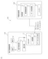
- FIG. 1 is a functional block diagram illustrating a configuration of a terminal connection management system according to an embodiment of the present disclosure.
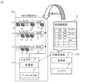
- 13 is a diagram explaining how the terminal connection status of the termination rack is reflected in the management function section of the portable device.
- FIG. 13 is a diagram explaining how the collation results in the management function section of the portable device are reflected on the display section of the termination rack.
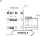
- FIG. FIG. 1 is a diagram illustrating a related technique.
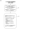
- 11 is a flowchart illustrating a process for mounting a portable device on a termination rack.
- 13 is a flowchart in the case where terminal information is reflected in a management function unit.
- 13 is a flowchart in the case where a collation result is reflected on a display unit.
- a terminal connection management system 300 according to an embodiment of the present disclosure will be described with reference to Fig. 1 to Fig. 7. First, the functional blocks of the terminal connection management system 300 will be described with reference to Fig. 1.
- the terminal connection management system 300 includes a terminal connection device 100 and a portable device 200.
- the terminal connection management system 300 is a system that grasps the terminal status and inputs, outputs, and checks the connection status of the terminals using the portable device 200 in the terminal connection device 100 that is located in a place where power supply is difficult or impossible, such as an underground manhole or outdoors.
- the terminal connection device 100 includes a plurality of terminals 10, a terminal detection unit 11, a display unit 12, and an input/output IF (Interface) 13.
- the terminal connection device 100 may be a termination rack for accommodating optical connectors that interconnect optical fiber cables.
- the input/output IF 13 includes a power supply unit 14 and a data input/output unit 15.
- the portable device 200 includes a memory unit 21 and a battery 24.
- the memory unit 21 includes a management function unit 22 and a data processing unit 23.
- the terminal connection management system 300 of the present disclosure includes: a terminal connection device (100) to which a terminal (10) can be connected and which detects a connection state of the terminal (10) when power is supplied from an external source;
- the terminal connection device includes a battery capable of supplying power to the terminal connection device, and a portable device that acquires the result of the detection in the terminal connection device.
- Each of the multiple terminals 10 is used to connect a communication cable with input and output.
- the multiple terminals 10 are used to connect an optical fiber cable.
- the number of terminals 10 is arbitrary as long as it is one or more.
- the terminal detection unit 11 has a function of detecting the connection state of each terminal 10, and the detection method is not important.
- the display unit 12 has a function of displaying information held by the portable device 200 so that the user can visually check it, and the display method is not important, but an LED may be used for display.
- the terminal detection unit 11 and the display unit 12 are shown as separate configurations, but they may be configured as one unit.
- the terminal detection unit 11 may be provided so as to correspond one-to-one to each terminal 10.
- each of the multiple terminals 10 may have a display unit 12.
- the power supply unit 14 is configured to be capable of receiving power from the battery 24 of the portable device 200.
- the data input/output unit 15 functions as an interface for exchanging information with the portable device 200.
- the input/output IF 13 is an interface for exchanging information, and also functions as an interface capable of receiving power from the battery 24.
- the portable device 200 is portable and can be carried around.
- the portable device 200 is a device that has both a function of storing information and a function as a battery.
- the portable device 200 may be, for example, a USB memory with a battery function added.
- the portable device 200 may also be equipped with a type of battery that supplies power by converting light energy into electrical energy.
- the management function unit 22 of the memory unit 21 stores the detection result by the terminal detection unit 11 and predetermined management information regarding the terminal 10.
- the management function unit 22 has a memory area, and holds management information (e.g., current/free/reserved, etc.) and terminal information (e.g., current/free, etc.) for each terminal 10 as data in the memory area.
- the data processing unit 23 of the memory unit 21 compares the detection result by the terminal detection unit 11 with the management information and records the comparison result in the management function unit 22. Specifically, the data processing unit 23 executes predetermined processing, such as reading and writing to the memory area of the management function unit 22.
- the terminal information is information indicating the current status of each terminal 10 detected by the terminal detection unit 11.
- the terminal information includes information indicating that the terminal 10 is attached to the terminal connection device 100 and in use, and information indicating that the terminal 10 has been removed from the terminal connection device 100.
- a terminal 10 that is in use is referred to as "currently in use”
- a terminal 10 that has been removed from the terminal connection device 100 is referred to as "empty.”
- the data processing unit 23 acquires the terminal information via the data input/output unit 15 of the input/output IF 13, and updates the storage area of the management function unit 22.
- the management information is information for managing each terminal 10, and includes, for example, information on the use status, reservation, abolition, etc. of each terminal 10.
- the information on the use status of each terminal 10 in the management information is, for example, information corresponding to the use status of each terminal 10 at the time of the previous terminal status confirmation.
- the terminal 10 being in use is referred to as "in use”
- the terminal 10 being removed from the terminal connection device 100 is referred to as "empty”.
- the terminal 10 being reserved is referred to as "reserved”
- the terminal 10 being abolished is referred to as "abolished”.
- the data processing unit 23 compares the terminal information with the management information, and executes a predetermined process according to the comparison result.
- the battery 24 supplies power only while the terminal detection unit 11 is detecting the state of the terminal 10 or while the data processing unit 23 is performing a predetermined process. In other words, the power of the battery 24 is used only for the terminal detection unit 11 to detect the state of the terminal 10 and the data processing unit 23 to perform a predetermined process.
- the terminal connection management system 300 of this embodiment allows the terminal connection device 100, which is located in a place where it is difficult or impossible to supply power, such as an underground manhole or outdoors, to use a portable device 200 equipped with a battery 24 to grasp the terminal status and input, output, and verify the terminal connection status while saving power.
- the user attaches the portable device 200 to the input/output IF 13.
- This electrically connects the power supply unit 14 and the battery 24, and connects the data input/output unit 15 and the storage unit 21.
- the terminal detection unit 11 detects the state of each terminal 10, and transmits terminal information corresponding to the detection result to the portable device 200 via the data input/output unit 15.
- the data processing unit 23 compares and verifies the terminal information stored in the storage area of the management function unit 22 with the terminal information from the terminal detection unit 11, and updates the terminal information of the terminal 10 that has changed. For example, if the terminal 10 stored in the storage area is "in use” but the current state of the terminal 10 is "empty," the data processing unit 23 updates the terminal information in the storage area from "in use” to "empty.”
- the data processing unit 23 compares the management information and terminal information in the storage area of the management function unit 22 for each terminal 10. If the management information and terminal information match (see terminals No. 1 and No. 2 in the figure), the data processing unit 23 does not perform any further processing on the terminal 10. In this case, for example, the data processing unit 23 may output null data. On the other hand, if the management information is "in use” and the terminal information is "empty” (see terminal No. 3 in the figure), the data processing unit 23 determines that the current usage status of the terminal 10 does not match the usage status at the time of the previous terminal status check, and records an unmatch in the storage area. Even if the management information is "empty" and the terminal information is "in use", the data processing unit 23 records an unmatch in the storage area.
- the power of the battery 24 is used only while the terminal detection unit 11 is detecting the state of the terminal 10 and the data processing unit 23 is reading, writing, and comparing data in the memory area of the management function unit 22. In other words, the power of the battery 24 is only used for the terminal detection unit 11 to detect the state of the terminal 10 and for the data processing unit 23 to perform specified processing.
- [Reflection on display] 3 it will be described how the collation result in the management function unit 22 of the portable device 200 is reflected on the display unit 12 of the terminal connection device 100.
- the display unit 12 displays a display corresponding to the collation result based on an instruction from the data processing unit 23.
- the power supply unit 14 and the battery 24 are electrically connected, and the data input/output unit 15 and the memory unit 21 are connected.
- the data processing unit 23 reflects the information held by the management function unit 22 on the display unit 12.
- the data processing unit 23 compares the terminal information from the terminal detection unit 11 with the management information from the management function unit 22.
- the data processing unit 23 records the comparison result, and displays the work instruction (insertion/removal) for the user on the display unit 12 via the data input/output unit 15. Furthermore, if there is a mismatch between the terminal information and the management information, it displays an instruction to confirm the mismatch on the display unit 12.
- the data processing unit 23 displays a "remove terminal” instruction on the display unit 12 of the No. 1 terminal. Specifically, the data processing unit 23 can display a "remove terminal” instruction on the No. 1 port provided on the display unit 12. Furthermore, since the No. 3 terminal in the figure is "in use” in the management information but “empty” in the terminal information, the data processing unit 23 can display a "check mismatch” instruction on the display unit of the No. 3 terminal. Specifically, the data processing unit 23 can display a "check mismatch” instruction on the No. 3 port provided on the display unit 12. Although not shown in the figure, if the management information is "open", a "insert terminal” instruction is displayed on the display unit 12 of the corresponding terminal 10.
- the power of the battery 24 is used only while these processes are being performed: terminal detection by the terminal detection unit 11, data reading/writing and matching in the memory area of the management function unit 22 by the data processing unit 23, instructions to the display unit 12, and display processing on the display unit 12.
- the terminal connection management system 300 of this embodiment can use a portable device 200 equipped with a battery 24 to indicate, in a power-saving manner, the terminal 10 that needs work or the terminal 10 that has a data mismatch, using an LED or the like, even in a terminal connection device 100 that is located in a place where power supply is difficult or impossible, such as an underground manhole or outdoors.
- Fig. 4 is a diagram for explaining the related art.
- the system of the related art includes a terminal connection device 100A having a plurality of terminals, and a terminal management table 200A.
- the work of inserting and removing terminals and the work of registering/correcting in the terminal management table 200A are performed by manually checking the actual terminal connection status and the terminal management table 200A.
- mismatches between the actual terminal connection status and the terminal management table 200A are likely to occur due to human error, etc., and problems such as incorrect connection/removal of terminals may occur. Therefore, there is a need to automatically reflect the terminal management status.
- the portable device 200 equipped with the battery 24 it is possible to grasp the terminal status and input, output, and compare the terminal connection status even for the terminal connection device 100 located in a place where power supply is difficult or impossible, such as an underground manhole or outdoors.
- the terminal 10 to be worked on or the terminal 10 with a data mismatch can be indicated by an LED or the like.
- the battery 24 since the battery 24 is used only during these processes, a power-saving system can be provided. In other words, the power of the battery 24 is used while either or both of the terminal connection device 100 and the portable device 200 are functioning.
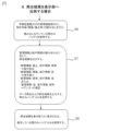
- Fig. 5 is a flowchart explaining the process when the portable device 200 is attached to the terminal connection device 100.
- Fig. 6 is a flowchart when the terminal information is reflected in the management function unit 22.
- Fig. 7 is a flowchart when the collation result is reflected in the display unit 12.
- the user installs the terminal detection unit 11 and the display unit 12 in the terminal connection device 100 (step S1). At this time, the terminal detection unit 11 and the display unit 12 are connected to the input/output IF 13.
- step S2 the user attaches the portable device 200 to the input/output IF 13 (step S2).
- the power supply unit 14 and the battery 24 are electrically connected, and the data input/output unit 15 and the storage unit 21 are connected.
- the terminal detection unit 11 detects the current state of each terminal 10 (step S3). At this time, in the terminal connection management system 300, the battery 24 is used only while the terminal detection unit 11 is detecting the state of each terminal 10. In other words, in step S3, the power of the battery 24 is used only for the terminal detection unit 11 to detect the state of each terminal 10.
- the data processing unit 23 compares and verifies the terminal information from the terminal detection unit 11 with the terminal information stored in the management function unit 22, and updates the terminal information of the terminal 10 for which a change has occurred (step S4).
- the battery 24 is used only while the data processing unit 23 is performing read and write processing on the management function unit 22.
- the power of the battery 24 is used only for the data processing unit 23 to perform read and write processing on the management function unit 22.
- the data processing unit 23 compares the terminal information in the storage area of the management function unit 22 with the management information, and records the comparison result in the storage area of the management function unit 22 (step S5). Specifically, if the management information is "in use” and the terminal information is also "in use”, or if the management information is "empty” and the terminal information is also "empty”, the data processing unit 23 outputs null data and does not perform any further processing. In other words, if the management information and the terminal information match, the data processing unit 23 outputs null data and does not perform any further processing.
- the data processing unit 23 determines that the current usage status of the terminal 10 does not match the usage status at the time of the previous terminal status check, and records an unmatch in the memory area. In other words, if the management information and the terminal information do not match regarding the usage status of the terminal 10, the data processing unit 23 records an unmatch in the memory area.
- the battery 24 is used only while the data processing unit 23 is performing data matching and recording the matching results in the memory area.
- the power of the battery 24 is used only for the data processing unit 23 performing data matching and recording the matching results in the memory area.
- the data processing unit 23 reads the instruction content (open, discontinue, etc.) from the management function unit 22 of the portable device 200 (step S6). At this time, in the terminal connection management system 300, the battery 24 is used only during the read process by the data processing unit 23. In other words, in step S6, the power of the battery 24 is used only for the read process by the data processing unit 23.
- the data processing unit 23 outputs the collation result according to the combination of the terminal information and the management information in the storage area of the management function unit 22 (step S7). Specifically, if the management information is "discontinued” and the terminal information is "in use”, the data processing unit 23 outputs an instruction to "remove terminal”. Also, if the management information is "open” and the terminal information is "empty”, the data processing unit 23 outputs an instruction to "insert terminal".
- the data processing unit 23 outputs an "unmatch confirmation" instruction.
- the battery 24 is used only during the data matching and matching result output process by the data processing unit 23.
- the power of the battery 24 is used only for the data matching and matching result output process by the data processing unit 23.
- the data processing unit 23 causes the display unit 12 to display a display corresponding to the output in step S7 (step S8).
- the battery 24 is used only while the data processing unit 23 is issuing instructions to the display unit 12 and the display processing is being performed on the display unit 12.
- the power of the battery 24 is used only for the data processing unit 23 issuing instructions to the display unit 12 and the display processing on the display unit 12.
- the device of the present disclosure can also be realized by a computer and a program, and is widely applicable regardless of the terminal, medium, or network.
- the program can also be recorded on a recording medium or provided via a network.
- the program of the present disclosure is a program for causing a computer to realize each function of the device of the present disclosure, and is a program for causing a computer to execute each procedure of the method executed by the device of the present disclosure.
- the data processing unit 23 of the portable device 200 of the present disclosure can be realized by a computer and a program, and the program can be recorded on a recording medium or provided via a network.
- Terminal detection unit 12 Display unit 13: Input/output IF 14: Power supply unit 15: Data input/output unit 21: Storage unit 22: Management function unit 23: Data processing unit 24: Battery 100: Terminal connection device 200: Portable device
Landscapes
- Engineering & Computer Science (AREA)
- Power Engineering (AREA)
- Power Sources (AREA)
Priority Applications (2)
| Application Number | Priority Date | Filing Date | Title |
|---|---|---|---|
| JP2025557363A JPWO2025104780A1 (cg-RX-API-DMAC7.html) | 2023-11-13 | 2023-11-13 | |
| PCT/JP2023/040755 WO2025104780A1 (ja) | 2023-11-13 | 2023-11-13 | 省電力可能な端子接続管理システム |
Applications Claiming Priority (1)
| Application Number | Priority Date | Filing Date | Title |
|---|---|---|---|
| PCT/JP2023/040755 WO2025104780A1 (ja) | 2023-11-13 | 2023-11-13 | 省電力可能な端子接続管理システム |
Publications (1)
| Publication Number | Publication Date |
|---|---|
| WO2025104780A1 true WO2025104780A1 (ja) | 2025-05-22 |
Family
ID=95742151
Family Applications (1)
| Application Number | Title | Priority Date | Filing Date |
|---|---|---|---|
| PCT/JP2023/040755 Pending WO2025104780A1 (ja) | 2023-11-13 | 2023-11-13 | 省電力可能な端子接続管理システム |
Country Status (2)
| Country | Link |
|---|---|
| JP (1) | JPWO2025104780A1 (cg-RX-API-DMAC7.html) |
| WO (1) | WO2025104780A1 (cg-RX-API-DMAC7.html) |
Citations (5)
| Publication number | Priority date | Publication date | Assignee | Title |
|---|---|---|---|---|
| JP2001285439A (ja) * | 2000-03-29 | 2001-10-12 | Rohm Co Ltd | 携帯電話装置および充電器 |
| US20080049627A1 (en) * | 2005-06-14 | 2008-02-28 | Panduit Corp. | Method and Apparatus for Monitoring Physical Network Topology Information |
| JP2010078549A (ja) * | 2008-09-29 | 2010-04-08 | Shinmaywa Industries Ltd | Usbメモリを用いた塵芥計量システム |
| US20150143153A1 (en) * | 2011-01-27 | 2015-05-21 | Commscope, Inc. | Automated infrastructure management systems and methods for enabling real time energy management |
| JP2020523832A (ja) * | 2017-06-05 | 2020-08-06 | コムスコープ テクノロジーズ リミティド ライアビリティ カンパニー | 複数のラックに設置されたインテリジェントパッチング装置のネイティブサポートを有するラックコントローラ |
-
2023
- 2023-11-13 JP JP2025557363A patent/JPWO2025104780A1/ja active Pending
- 2023-11-13 WO PCT/JP2023/040755 patent/WO2025104780A1/ja active Pending
Patent Citations (5)
| Publication number | Priority date | Publication date | Assignee | Title |
|---|---|---|---|---|
| JP2001285439A (ja) * | 2000-03-29 | 2001-10-12 | Rohm Co Ltd | 携帯電話装置および充電器 |
| US20080049627A1 (en) * | 2005-06-14 | 2008-02-28 | Panduit Corp. | Method and Apparatus for Monitoring Physical Network Topology Information |
| JP2010078549A (ja) * | 2008-09-29 | 2010-04-08 | Shinmaywa Industries Ltd | Usbメモリを用いた塵芥計量システム |
| US20150143153A1 (en) * | 2011-01-27 | 2015-05-21 | Commscope, Inc. | Automated infrastructure management systems and methods for enabling real time energy management |
| JP2020523832A (ja) * | 2017-06-05 | 2020-08-06 | コムスコープ テクノロジーズ リミティド ライアビリティ カンパニー | 複数のラックに設置されたインテリジェントパッチング装置のネイティブサポートを有するラックコントローラ |
Also Published As
| Publication number | Publication date |
|---|---|
| JPWO2025104780A1 (cg-RX-API-DMAC7.html) | 2025-05-22 |
Similar Documents
| Publication | Publication Date | Title |
|---|---|---|
| US7263582B2 (en) | System and method for raid configuration | |
| CN101494564B (zh) | 一种电源监控装置及单板热备份的实现方法 | |
| US8996778B2 (en) | Cable adapter correlation in a cluster | |
| TWI412921B (zh) | 電子裝置、電子裝置的電力開啟方法及程式 | |
| CN105278061B (zh) | 用于odn设备的智能化装置、设备、方法及系统 | |
| CN104484264A (zh) | 一种硬盘状态指示方法及装置 | |
| US20200097429A1 (en) | Rack controller with native support for intelligent patching equipment installed in multiple racks | |
| US7734858B2 (en) | Fabric interposer for blade compute module systems | |
| CN107832193A (zh) | 一种基于i2c总线的多板卡状态监控方法 | |
| US7694029B2 (en) | Detecting miscabling in a storage area network | |
| CN113110978B (zh) | 一种硬盘背板灯控制装置及方法 | |
| CN119030826A (zh) | 一种多总线自适应协议智能物联网网关系统 | |
| CN111124455A (zh) | 一种电池管理系统升级方法、装置、服务器及存储介质 | |
| GB2415526A (en) | System and method of SCSI and SAS hardware validation | |
| CN102590956B (zh) | 光纤连接器管理装置及方法 | |
| CN111294413A (zh) | 一种互联网协议ip地址的确定方法、装置和可读介质 | |
| CN117667818A (zh) | 信号传输结构、服务器以及信号传输方法 | |
| US7045717B2 (en) | High speed cable interconnect to a computer midplane | |
| WO2024108938A1 (zh) | 一种硬盘控制装置、方法、设备、非易失性可读存储介质及服务器 | |
| CN113890845B (zh) | Pse测试方法、装置、存储介质及电子设备 | |
| CN120723849A (zh) | 硬盘盘序识别方法、电子设备及服务器 | |
| US8151011B2 (en) | Input-output fabric conflict detection and resolution in a blade compute module system | |
| ES2927518T3 (es) | Sistema de gestión de infraestructuras con soporte para cables breakout | |
| US7254016B1 (en) | Data storage system with improved serviceability features | |
| CN115114212B (zh) | 一种vpd刷写方法、装置、设备及介质 |
Legal Events
| Date | Code | Title | Description |
|---|---|---|---|
| 121 | Ep: the epo has been informed by wipo that ep was designated in this application |
Ref document number: 23958793 Country of ref document: EP Kind code of ref document: A1 |
|
| ENP | Entry into the national phase |
Ref document number: 2025557363 Country of ref document: JP Kind code of ref document: A |
|
| WWE | Wipo information: entry into national phase |
Ref document number: 2025557363 Country of ref document: JP |
|
| NENP | Non-entry into the national phase |
Ref country code: DE |