WO2025100489A1 - 無針注射器 - Google Patents
無針注射器 Download PDFInfo
- Publication number
- WO2025100489A1 WO2025100489A1 PCT/JP2024/039627 JP2024039627W WO2025100489A1 WO 2025100489 A1 WO2025100489 A1 WO 2025100489A1 JP 2024039627 W JP2024039627 W JP 2024039627W WO 2025100489 A1 WO2025100489 A1 WO 2025100489A1
- Authority
- WO
- WIPO (PCT)
- Prior art keywords
- syringe
- control circuit
- injection
- predetermined value
- user
- Prior art date
- Legal status (The legal status is an assumption and is not a legal conclusion. Google has not performed a legal analysis and makes no representation as to the accuracy of the status listed.)
- Pending
Links
Images







Classifications
-
- A—HUMAN NECESSITIES
- A61—MEDICAL OR VETERINARY SCIENCE; HYGIENE
- A61M—DEVICES FOR INTRODUCING MEDIA INTO, OR ONTO, THE BODY; DEVICES FOR TRANSDUCING BODY MEDIA OR FOR TAKING MEDIA FROM THE BODY; DEVICES FOR PRODUCING OR ENDING SLEEP OR STUPOR
- A61M5/00—Devices for bringing media into the body in a subcutaneous, intra-vascular or intramuscular way; Accessories therefor, e.g. filling or cleaning devices, arm-rests
- A61M5/178—Syringes
- A61M5/30—Syringes for injection by jet action, without needle, e.g. for use with replaceable ampoules or carpules
Definitions
- the present invention relates to a needleless syringe.
- a protruding member is provided at a first position so as to protrude from an end face of the housing.
- a voltage is applied to the drive unit to inject the injection target substance.
- the injection depth can vary depending on the pressure with which the nozzle is pressed against the skin. For example, if the needle-free syringe is pressed with an appropriate pressure of a specified value or more, the target substance is injected intradermally (shallow area beneath the skin), whereas if the pressure is too small, the target substance may pass through the skin and reach the muscle.
- the goal is to inject intradermally (target area to be injected), but if the pressure with which the needle-free syringe is pressed against the skin is too small and the injection solution is injected deep enough to reach the muscle, the effect of the target substance may not be fully achieved.
- the technology disclosed herein has been developed in light of the above-mentioned circumstances, and aims to provide a needleless syringe that makes it possible to administer an injection target substance to a desired depth.
- the needleless syringe of the present disclosure comprises: A syringe assembly including a container for accommodating an injection objective substance, and a driver having a mechanism for pressurizing the injection objective substance and ejecting the injection objective substance from a nozzle formed at the tip of the container; and a housing to which the syringe assembly is attached.
- the needle-free syringe may further include a notification unit that notifies a user of the result of the first determination made by the control circuit.
- the control circuit may make a second judgment that the driver cannot be operated when the pressure detected by the sensor is equal to or greater than a second predetermined value that is greater than the first predetermined value.
- the needle-free syringe may further include a notification unit that notifies a user of the result of the first judgment or the result of the second judgment.
- the notification unit issues a first notification to the user when the pressing force is equal to or greater than the first predetermined value and less than the second predetermined value, and issues a second notification to the user when the pressing force is equal to or greater than the second predetermined value;
- the first notification and the second notification may have different contents.
- the syringe assembly is removably attached to the housing;
- the sensor may be disposed between the syringe assembly and the housing.
- the needleless syringe may have multiple sensors arranged symmetrically about the central axis of the syringe assembly.
- the needleless syringe comprises:
- the nozzle has a nozzle tip including an injection port for the injection objective substance, the nozzle tip being arranged around a predetermined axis along a pressing direction against the injection target area;
- the plurality of sensors may be disposed at positions symmetrical with respect to the predetermined axis.
- the control circuit may store log data in memory indicating the pressure applied when the injection target substance was ejected, display the log data on a display unit, or transmit the log data to an external device.
- the control circuit may be capable of setting the first predetermined value based on at least one of a user input, the type of the substance to be injected, the type of the container, and the injection target.
- control circuit may drive the driver to eject the injection target substance from the nozzle.
- the present disclosure provides a needleless syringe that allows the injection target substance to be administered to a desired depth.
- FIG. 10 is a diagram showing the control method executed by the control circuit of the syringe.
- FIG. 11 is a diagram showing a configuration of a nozzle according to a modified example.
- FIG. 12 is a diagram showing an arrangement of sensors in a modified example.
- FIG. 13 is a diagram showing a control method according to the second embodiment.
- the syringe 1 is a needleless syringe that uses the combustion energy of explosives to inject a liquid corresponding to the injection target substance of the present application into an injection target area (hereinafter, simply referred to as a target area), that is, a device that performs an injection by injecting the liquid into the target area without using an injection needle.
- a target area an injection target area
- the injection target substance is described as an injection liquid, but there is no intention to limit its form, and for example, the injection target substance may be in powder form.
- the present disclosure is not limited by the embodiments, but is limited only by the claims.
- the terms "tip side” and "base side” are used to represent the relative positional relationship in the longitudinal direction of the syringe 1.
- the "tip side” refers to the position closer to the tip of the syringe 1, i.e., closer to the injection port 77, which will be described later
- the “base side” refers to the direction opposite to the "tip side” in the longitudinal direction of the syringe 1, i.e., the direction toward the igniter 22 in the syringe assembly 10 (see FIG. 5, which will be described later).
- FIG. 1 is a diagram showing a schematic appearance of a syringe 1.
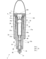
- FIG. 2 is a first cross-sectional view of the syringe 1, which is a cross-section taken along line AA in FIG. 4 described later.
- FIG. 3 is a second cross-sectional view of the syringe 1, which is a cross-section taken along line BB in FIG. 4 described later, which is perpendicular to the cross-section AA.
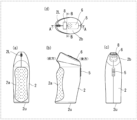
- FIG. 4 is a diagram showing a configuration of a housing 2 constituting the syringe 1
- FIG. 5 is a diagram showing a schematic configuration of a syringe assembly 10.
- the syringe 1 is formed by attaching a syringe assembly 10 to a housing 2.
- the housing 2 incorporates a control circuit 3 and a sensor 4.
- a cable 9 (FIG. 1) for supplying a drive current to a driver 20 in the syringe assembly 10 is connected to the housing 2.
- the ejected liquid that is ejected into the target area by the syringe 1 is formed by incorporating a specific substance that exerts the efficacy or function expected in the target area into a liquid medium.
- the specific substance may be in a dissolved state in the liquid medium, or it may simply be in a mixed state without being dissolved.
- the specified substance contained in the injection liquid examples include biologically derived substances that can be injected into a target area that is a living organism, and substances that exhibit the desired physiological activity.
- biologically derived substances include DNA, RNA, nucleic acids, antibodies, cells, etc.
- biologically active substances include medicines made of low molecular weight molecules, proteins, peptides, etc., vaccines, inorganic substances such as metal particles for thermotherapy and radiotherapy, and substances with various pharmacological and therapeutic effects including carriers.
- the liquid medium for the injection liquid may be any substance suitable for administering these specified substances into the target area, and may be water-based or oil-based.
- there are no particular limitations on the viscosity of the liquid medium so long as the specified substance can be injected with the syringe 1.
- the syringe assembly 10 is configured to be detachable from the housing 2.
- a storage space 75 formed between a container (storage section) 70 and a plunger 80 included in the syringe assembly 10 is filled with the injection liquid in a preparation stage before the syringe 1 is actuated, and the syringe assembly 10 is a unit that is replaced each time the injection liquid is to be injected. Details of the syringe assembly 10 will be described later.
- the housing 2 is formed with a grip portion 2a that is held by the user of the syringe 1 for use, and is provided with a number of switches for operating the syringe 1 to realize the injection of the injection liquid.
- the syringe 1 is configured so that the user can hold it with one hand and operate it.
- FIG. 4 shows the appearance of the housing 2 when viewed from the front, (b) shows the appearance of the housing 2 when viewed from the side, (c) shows the appearance of the housing 2 when viewed from the rear, and (d) shows the appearance of the housing 2 when viewed from above.
- the "front” refers to the part located distal to the user when the user holds the housing 2, which is located on the left side in FIG. 4(b), and the “rear” refers to the part located proximal to the user, which is located on the right side in FIG. 4(b). Therefore, when the user holds the housing 2 with one hand, the fingertips are placed on the front of the housing 2, which is the distal side, and the wrist is in a state close to the rear of the housing 2, which is the proximal side. Additionally, “upper” refers to the area toward the base end of the syringe 1.
- a grip portion 2a is provided near the front of the housing 2 to make it easier for the user's fingertips to grip.
- Multiple dimples are formed in the grip portion 2a to improve the grip of the user's fingertips.
- the outer periphery on the front side of the grip portion 2a is gently uneven (see FIG. 4(b)), making it easier for the user's index finger and middle finger to grip it.
- the housing 2 is provided with a first switch 5 and a second switch 6, which are two operation switches for operating the syringe 1.
- the first switch 5 and the second switch 6 are connected to a control unit such as a microcontroller as described below, and the control unit controls the supply of ignition current to the igniter 22 based on signals from each switch, thereby controlling the operation of the syringe 1.
- the first switch 5 is a slide-type switch provided at the rear of the housing 2, and the sliding direction is the up-down direction of the housing 2 (the direction connecting the tip and the base end).
- the first switch 5 is constantly biased in the upward direction, and the user can bring the syringe 1 into a standby state by continuing to slide the first switch 5 downward (toward the tip end) against the biasing force for a certain period of time.
- the standby state is a state in which the syringe 1 is ready to eject the ejection liquid, and ejection is performed if an additional operation is performed by the user.
- the user can release the standby state of the syringe 1 by continuing to slide the first switch 5 downward against the biasing force for a certain period of time.
- the second switch 6 is a push-down switch provided on the upper inclined surface 2b of the housing 2, and the user can push the second switch 6 inwardly of the housing 2.
- the control unit is configured to supply an ignition current to the igniter 22 by pushing the second switch 6.
- a display unit 8 is provided on the upper inclined surface 2b of the housing 2.
- the display unit 8 is one form of a notification unit that displays the determination result by the control circuit 3 and notifies the user.
- the notification unit is not limited to the display unit 8, and may be an indicator, a speaker, a communication module, or the like.
- a connector 2L to which a cable 9 is connected is provided on the upper front inclined surface 2c of the housing 2. In this embodiment, the connector 2L is a USB connector, and the cable 9 is detachable from the housing 2.
- the power for operating the igniter 22 is supplied from the outside via the cable 9.
- a battery for supplying the power may be provided inside the housing 2. In this case, as long as the battery has power remaining, the housing 2 can be used repeatedly while replacing the syringe assembly 10. When the battery runs out of power, the battery can be replaced or charged.
- the lower surface (tip surface) 2u of the housing 2 is provided with an opening 2d for inserting the syringe assembly 10, and an accommodation space 2e (Fig. 2) for the syringe assembly 10 extends upward from this opening 2d.
- the accommodation space 2e has a shape corresponding to the syringe assembly 10, and is generally cylindrical in this embodiment.
- the socket 7 and sensor 4 are disposed at the upper end of the accommodation space 2e.
- the syringe assembly 10 is attached to the housing 2 to form the syringe 1.
- the syringe assembly 10 of this embodiment is an assembly including a driver (driving unit) 20, an attachment 30, a container 70, and a plunger 80. The assembly of the syringe assembly 10 will be described later.
- the driver 20 has a mechanism in which the igniter 22 is the actuation source and the piston 40 is the output section.
- a portion of the container 70 is generally placed in the area on the tip side.
- the area in which the container 70 is placed communicates with the area in which the plunger 80 is placed on its base end side, and the tip side opens to the tip surface of the attachment 30.
- a female threaded portion 36 for attaching the container 70 is formed on the inner wall of the area in which the container 70 is placed.
- the female threaded portion 36 screws into the male threaded portion 74 of the container 70 shown in Figures 6 and 7 described below, thereby realizing the connection between the attachment 30 and the container 70.
- the plunger 80 is a member that pressurizes the liquid to be ejected by the energy received from the piston 40, and has a plunger rod 81 and a stopper portion 82.
- the plunger rod 81 is formed, for example, from a resin material suitable for pressurization, but is not limited thereto and may be formed, for example, from the same type of material as the attachment 30.
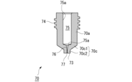
- FIG. 6 is a cross-sectional view showing the general configuration of container 70
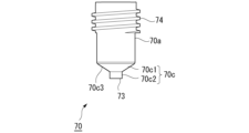
- FIG. 7 is an external view showing the general configuration of container 70.
- Container 70 is a member that holds the injection liquid and defines a flow path for injecting the injection liquid pressurized by plunger 80 into a target area.
- Container 70 is made of a material that takes into consideration the pressurization by the plunger and the determination of the flow path.
- container 70 is made of a resin material. Note that container 70 is not limited to a resin material and can be made of the same type of material as attachment 30, for example.
- the nozzle 70c has a nozzle tip portion 70c2 that includes a part of the flow path 76 on the injection port 77 side, and is configured to have a tapered portion 70c1 that connects the nozzle tip portion 70c2 and the body portion 70a and includes a tip side outer surface 70c3 that is inclined with respect to the central axis of the attachment 30 in the longitudinal direction.
- a position shift prevention device 50 described later is fitted onto the outer periphery of the nozzle tip portion 70c2.
- the tip side of the plunger 80 is fitted into the storage space 75 of the container 70 so that the stopper portion 82 of the plunger 80 can slide within the storage space 75 toward the nozzle 70c (toward the tip side).
- the space formed between the stopper portion 82 of the plunger 80 and the container 70 becomes a storage space for the injection liquid, i.e., a space in which the injection liquid is sealed.
- the tip surface of the stopper portion 82 and the inner wall surface of the container 70 located on the tip side of the tip surface of the stopper portion 82 define the storage space.
- the tip shape of the stopper portion 82 of the plunger 80 is formed so as to generally match the tip shape of the storage space 75 defined by the inner wall surface 75a near the portion where the storage space 75 and the flow path 76 are connected (the innermost part of the storage space 75).
- the tip shape of the stopper portion 82 and the tip shape of the storage space 75 are both tapered shapes that decrease in diameter toward the tip side.
- the shape of the stopper portion 82 is not limited to a specific shape as long as the desired effect is obtained in the syringe 1 of this embodiment.
- the stopper portion 82 is formed with an outer diameter slightly larger than the storage space 75 of the container 70, so that when it is fitted into the storage space 75 in a radially compressed state, it makes suitable contact with the inner wall surface 75a so as to maintain airtightness between the stopper portion 82 and the container 70.
- the outer diameter of the stopper portion 82 does not have to be formed larger than the storage space 75, and may be approximately the same as the diameter of the storage space 75, as long as the appropriate injection liquid can be injected.
- the amount of pulling back of the plunger 80 at this time is set to an amount that allows the plunger 80 (plunger rod 81) protruding from the container 70 to reach the area in the internal space of the attachment 30 where the piston 40 is disposed when the container 70 is attached to the attachment 30 in this state.
- the plunger 80 When the driver 20 is attached to the attachment 30 to which the container 70 and plunger 80 are attached as described above, the plunger 80 is pushed from the piston 40 toward the tip side, and the plunger 80 is positioned at a predetermined position (pre-operation position) within the container 70. At this time, in response to the pushing of the plunger 80, excess injection liquid within the container 70 is discharged from the injection port 77, and a predetermined amount of injection liquid is left in the container 70.
- the volume of the space for containing the injection liquid formed between the plunger 80 positioned at the pre-operation position and the container 70 is determined to a volume that ensures an appropriate injection amount of the injection liquid when the syringe 1 is operated. Therefore, when the syringe assembly 10 is assembled as described above, the amount of injection liquid contained in the accommodation space 75 of the container 70, i.e., the amount of injection liquid to be injected, is set to a predetermined amount.
- the syringe assembly 10 configured in this manner is attached to the housing 2 by inserting the base end portion into the accommodation space 2e of the housing 2 and fitting the ignition pin 22b of the igniter 22 into the socket 7 on the housing 2 side. At this time, the base end surface 101 of the syringe assembly 10 abuts against the sensor 4.
- the syringe assembly 10 may have a configuration in which, when the ignition pin 22b fits into the socket 7 on the housing 2 side, the syringe assembly 10 is held so as not to fall out of the housing 2.
- the syringe assembly 10 may also have a configuration in which the outer wall of the syringe assembly 10 abuts against the inner wall 2h that defines the accommodation space 2e and is tightly fitted, thereby holding the syringe assembly 10 so as not to fall out of the housing 2.
- the syringe assembly 10 is loaded into the housing 2, and the syringe 1 is prepared for use (see Figures 1 to 3).
- the user holds the housing 2 of the syringe 1 in one hand and keeps sliding the first switch 5 located at the rear of the housing 2 for a predetermined time to put the syringe 1 into a standby state.
- the user then presses the nozzle 70c against the target area, and, as described below, presses the second switch 6 when notified that the pressing force is appropriate. This activates the igniter 22, pressurizing the ejection liquid via the piston 40 and plunger 80, and the ejection liquid is ejected from the ejection port 77 and injected into the target area.
- the sensor 4 detects the pressure when the nozzle 70c of the syringe 1 is pressed against the injection target area, and inputs the pressure to the control circuit 3.
- the sensor 4 has, for example, a piezoelectric element, and converts the magnitude of distortion when pressure is applied into an electric signal by the piezoelectric element.
- the sensor 4 may also detect a change in capacitance caused by distortion when pressure is applied to a cell having multiple electrodes.
- the method of detecting the pressure of the sensor 4 is not particularly limited, and it is sufficient that the value of the pressure can be input to the control circuit 3 as an electric signal.
- the sensor 4 When the start operation is performed on the first switch 5 and the syringe 1 is in a standby state, the sensor 4 repeatedly detects the pressure at a period of, for example, several milliseconds to 1 second, and inputs the pressure to the control circuit 3.
- the sensor 4 is provided on the upper wall 2f of the storage space 2e of the housing 2, located above the storage space 2e, and is sandwiched between the base end of the syringe assembly 10 and the upper wall 2f of the storage space when the syringe assembly 10 is stored in the storage space 2e. That is, the sensor 4 is disposed between the container 70 attached to the syringe assembly 10 and the upper wall 2f of the storage space of the housing 2.
- this reaction force is transmitted from the base end of the syringe assembly 10 to the sensor 4, and the sensor 4 detects this reaction force (pressing force).
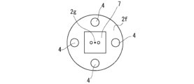
- FIG. 8 is a diagram showing an example of the arrangement of the sensors 4 provided on the upper wall 2f of the storage space.
- a plurality of sensors 4 (four in this example) are provided and are arranged at positions that are rotationally symmetrical about the predetermined axis 2g.
- the predetermined axis 2g coincides with the central axis of the storage space 2e.
- the predetermined axis 2g also coincides with the central axis of the syringe assembly 10 and the central axis of the container 70.
- the sensors 4 are arranged at positions that are symmetrical about the central axis of the container 70.
- the control circuit can determine whether the syringe 1 is correctly pressed perpendicular to the surface of the target area.
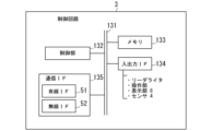
- Control circuit> 9 is a diagram showing the configuration of the control circuit 3.
- the control circuit 3 is a computer having a control unit 132, a memory (storage device) 133, an input/output IF (interface) 134, and a communication IF 135, which are connected to each other by a connection bus 131.
- the control unit 132 processes input information and outputs the processing result, thereby controlling the entire device.
- the control unit 132 is also called a CPU (Central Processing Unit) or an MPU (Micro-processing unit).
- the control unit 132 is not limited to a single processor, and may have a multi-processor configuration. In addition, the control unit 132 may have a multi-core configuration having multiple cores in a single chip connected by a single socket.
- the memory 133 may be a main storage device or an auxiliary storage device.
- the main storage device is used, for example, as a working area for the control unit 132, a storage area for temporarily storing information processed by the control unit 132, and a buffer area for communication data.
- the main storage device is a storage medium for the control unit 132 to cache programs and data or to use as a working area.
- the main storage device includes, for example, a RAM (Random Access Memory), a ROM (Read Only Memory), and a flash memory.
- the auxiliary storage device is a storage medium for storing programs executed by the control unit 132, data used for information processing, setting information for operations, and the like.
- the auxiliary storage device is, for example, a Solid State Drive (SSD), an EPROM (Erasable Programmable ROM), a flash memory, a USB memory, a memory card, and the like.
- the auxiliary storage device may store setting information for the syringe 1, judgment conditions, a history (log) of the detected pressing force, and the like.
- the input/output IF 134 is an interface that inputs and outputs data between the control circuit 3 and peripheral devices connected thereto.
- the input/output IF 134 inputs and outputs data between devices such as a reader/writer that reads and writes data to storage media such as flash memory and SSD, an operation unit, a display unit, a speaker, and a sensor.
- the operation unit is an input unit that inputs information to the control circuit 3 by user operation, such as an operation button, a selection key, or a touch panel.
- the display unit 8 is an output unit that displays and outputs information such as the judgment result of the control unit 132 to the user.
- the touch panel may be arranged so as to overlap with the display area of the display device, and may be configured to detect touch operations on icons displayed on the display device and input them to the control circuit 3.
- the operation unit of this embodiment has a first switch 5 and a second switch 6.
- the operation unit may also input a first predetermined value and a second predetermined value to the control circuit 3 by user operation and set them.
- the control circuit 3 may also store statistical data and data tables in advance in memory, and when the user operates the operation unit to input information on the injection target substance (type of medicinal liquid to be used, amount, type of container, etc.) and information on the subject to be administered (gender, age, body fat percentage, administration site, etc.), the control circuit 3 may set the first and second predetermined values based on this information.
- the communication IF 135 is an interface (communication module) that communicates with other devices via a communication line (network), and is also referred to as a CCU (Communication Control Unit).
- the communication IF 135 has a wired IF 51 that performs wired communication, and a wireless IF 52 that performs wireless communication.
- the wired IF 51 communicates with other devices, for example, via a cable 9.
- the wireless IF 52 communicates with other devices, for example, via a WLAN.
- the wireless IF 52 in this embodiment employs a communication line defined by IEEE 802.11, but is not limited to this and may use, for example, a communication line using Bluetooth (registered trademark).
- control unit 132 realizes the functions described below based on an application program. That is, the control unit 132 realizes the required functions by software. However, some or all of the functions may be realized by hardware such as a dedicated LSI (large scale integration) such as a DSP (Digital Signal Processor), an ASIC (Application Specific Integrated Circuit), an FPGA (Field-Programmable Gate Array), a logic circuit, or other digital circuit. Furthermore, at least a part of the hardware may include an analog circuit.
- the control unit 132 may be configured such that one processor functions as multiple processing units, or may be configured to have multiple processors functioning as one processing unit.
- the control circuit 3 acquires the pressure detected by the sensor 4, and when the pressure reaches or exceeds a first predetermined value, makes a first judgment that the driver 20 can be operated. Furthermore, when the pressure detected by the sensor 4 exceeds a second predetermined value that is greater than the first predetermined value, the control circuit 3 makes a second judgment that the driver 20 cannot be operated.
- the control circuit 3 notifies the user by displaying the results of the first and second judgments on the display unit 8. Note that the notification to the user is not limited to a display on the display unit 8, but may also be a notification by sound output from a speaker, information transmission from the CCU to a user terminal, or vibration by a vibrator, etc.
- the control circuit 3 issues a first notification to the user when the pressure is equal to or greater than the first predetermined value and is within a range not exceeding the second predetermined value.
- the control circuit 3 issues a second notification to the user when the pressure is equal to or greater than the second predetermined value or when the pressure is equal to or less than the first predetermined value.
- the control circuit 3 displays the text "operable” as the first notification and “not operable” as the second notification on the display unit 8.
- the control circuit 3 may also output these "operable” and “not operable” as voice messages from the speaker.
- the control circuit 3 may also display a color according to the notification by an indicator, such as "green” for the first notification and "red” for the second notification. In this way, the control circuit 3 can accurately inform the user that the injection pressure has been reached (first notification) and that injection is not possible due to excessive or insufficient pressure being applied (second notification) by making the contents of the first notification and the second notification different from each other.
- Fig. 10 is a diagram showing a control method executed by the control circuit 3 of the syringe 1.
- the control circuit 3 starts the processing of Fig. 10.
- step S10 the control circuit 3 acquires information on the injection objective substance and information on the injection target.
- the control circuit 3 acquires information on the injection objective substance and information on the injection target input by the user from the operation unit.
- the control circuit 3 may also acquire information on the injection objective substance and information on the injection target from another device via the cable 9 or a wireless communication line.
- step S20 the control circuit 3 sets a first predetermined value and a second predetermined value based on the information on the injection target substance and the information on the injection subject acquired in step S10.
- the second predetermined value is a value larger than the first predetermined value, for example, 60N.
- the first predetermined value may be 3N to 10N
- the second predetermined value may be 30N to 80N.
- step S30 the control circuit 3 acquires the pressure detected by the sensor 4, and determines whether the driver 20 can be operated based on whether the pressure reaches or exceeds a first predetermined value. If the pressure is equal to or exceeds the first predetermined value and the determination is affirmative, the control circuit 3 proceeds to step S40, and if the determination is negative, the control circuit 3 proceeds to step S100.
- step S40 the control circuit 3 obtains the pressure detected by the sensor 4 and determines whether the driver 20 is inoperable based on whether the pressure is equal to or greater than the second predetermined value, or, after it has been determined that the pressure is equal to or greater than the first predetermined value, whether it falls below the first predetermined value. If the control circuit 3 determines that the pressure is less than the second predetermined value, it proceeds to step S50, and if the control circuit 3 determines that the pressure is equal to or greater than the second predetermined value, it proceeds to step S110.
- step S50 the control circuit 3 determines whether the syringe 1 is being pressed at an angle based on the detection values of the multiple sensors 4. If the difference between the detection values of the sensors 4 is less than a predetermined value, the control circuit 3 determines that the syringe 1 is not being tilted and is being pressed appropriately, and proceeds to step S60. On the other hand, if the difference between the detection values of the sensors 4 is equal to or greater than the predetermined value, the control circuit 3 determines that the syringe 1 is being pressed at an angle, and proceeds to S120.
- step S60 the control circuit 3 causes the display unit 8 to display information indicating that ejection is possible (ejection possible information) as a first notification.
- the ejection possible information include text such as "ejection possible", a numerical value of the pressing force, or a graph showing the pressing force.
- the first notification may be, for example, changing the displayed text or background color to a specific color (e.g., green), outputting a specific sound, or a combination of these.
- step S70 the control circuit 3 determines whether the second switch 6 has been pressed, and if the determination is positive, the process proceeds to step S80, and if the determination is negative, the process proceeds to step S30.
- step S80 the control circuit 3 supplies a drive current (ignition current) to the driver 20 to operate the driver 20.
- step S90 the control circuit 3 acquires the pressure detected by the sensor 4 during ejection, and stores the detected value of the pressure in the memory 133 as a log.
- the control circuit 3 may be configured to display the log data on the display unit 8, or to transmit the log data to an external device. This allows the control circuit 3 to later check whether the ejection was performed with an appropriate pressure, etc.
- step S50 the control circuit 3 causes the display unit 8 to display tilt information indicating that the syringe 1 has been pressed at an angle and that the syringe 1 is tilted.
- tilt information include text such as "tilted too much" and an icon indicating that the syringe is tilted.
- the notification of the tilt may be, for example, by changing the displayed text or background color to a specific color (e.g., blue), by outputting an error sound, or by a combination of these.
- guidance indicating in which direction the syringe should be re-standing may be displayed on the display unit 8.
- the control circuit 3 of the syringe 1 makes a second judgment that the driver 20 cannot be operated when the pressing force detected by the sensor 4 is equal to or greater than a second predetermined value that is greater than the first predetermined value. This allows the syringe 1 to perform injections with an appropriate pressing force, preventing damage to the container, etc., reducing the load on the syringe 1, and avoiding breakdowns.
- the syringe assembly 10 is removably attached to the housing 2, and the sensor 4 is disposed between the syringe assembly 10 and the housing 2. This prevents the sensor 4 from directly touching the area to be injected, allowing injections to be performed hygienically.
- multiple sensors 4 are arranged in positions that are symmetrical about the central axis of the syringe assembly 10. This allows the sensors 4 to detect the inclination of the syringe 1 relative to the area to be injected. The inclination is then notified to the user, allowing the user to understand the inclination and perform the injection in the correct position with the syringe 1 perpendicular to the surface of the area to be injected.
- the control circuit 3 stores log data indicating the pressure applied when the injection target substance was ejected in memory, displays the log data on the display unit 8, or transmits the log data to an external device. This allows the syringe 1 to keep a record of the pressure applied during injection, and allows the user to determine the validity of the injection in case of later verification.
- the control circuit 3 can set the first predetermined value based on at least one of the user's input, the type of substance to be injected, the type of container, and the injection target. This allows the user to set each predetermined value in detail by operating the operation unit of the syringe 1.
- the notification unit of the syringe 1 is a display unit that displays the pressing force numerically or graphically. This allows the user to accurately understand the pressing force numerically or graphically.
- FIG. 11 is a diagram showing the configuration of the nozzle 70c according to the modified example
- FIG. 12 is a diagram showing the positional relationship between the sensor 4 and the nozzle tip 70c2 in the modified example.
- FIG. 12 shows the upper wall 2f of the accommodation space to which the sensor 4 is attached and the nozzle tip 70c2 superimposed as seen from the tip side of the syringe assembly 10 loaded in the accommodation space 2e.
- FIG. 12 shows other configurations such as the socket 7, the body 21, the attachment 30, etc.
- the nozzle tip 70c2 is shown by a two-dot chain line.
- This modified example is different from the first embodiment described above in that a plurality of nozzle tips 70c2 are provided. Note that the other configurations are the same as those in the first embodiment described above, and therefore repeated explanations will be omitted by assigning the same reference numerals to the same elements.
- multiple nozzle tips 70c2 in this modified example are provided at the tip of the nozzle 70c.
- FIG. 11 shows an example in which three nozzle tips 70c2 are provided, this is not limited to this, and the number of nozzle tips 70c2 may be two or four or more.
- the multiple nozzle tips 70c2 are arranged around a predetermined axis 70x that is aligned with the pressing direction of the syringe 1.
- the specified axis 70x coincides with the specified axis 2g located at the center of the multiple sensors 4.
- the multiple sensors 4 are arranged at positions that are rotationally symmetrical around the specified axis 70x. This allows the syringe of this modified example to detect the inclination of the syringe 1 relative to the injection target area. Then, by notifying the user of this inclination, the user can be allowed to perform the injection in the correct position where the syringe 1 is perpendicular to the surface of the injection target area.
- Second Embodiment This embodiment is different from the first embodiment described above in that ejection is not triggered by pressing the second switch 6, but rather the control circuit 3 ejects when an ejection is possible. Since the other configurations are the same as those of the first embodiment described above, the same elements are given the same reference numerals and will not be described again.
- Fig. 13 is a diagram showing a control method according to the second embodiment.
- the processes from step S10 to step S50 are the same as those in Fig. 10.
- the control circuit 3 outputs information (pre-notification information) notifying the injection.
- the control circuit 3 outputs the information to be displayed on the display unit 8.
- Examples of the output of the pre-notification information include displaying text such as "injection timer starts in 5 seconds" or "preparation for injection completed", or a countdown until injection.
- examples of the output of the pre-notification information include displaying text or a background color of a specific color (e.g., purple), outputting a specific sound or voice, or a combination of these.
- step S70A the control circuit 3 determines whether a predetermined time has elapsed since the first notice was given, and if the determination is positive, the process proceeds to step S80, and if the determination is negative, the process proceeds to step S30. Note that the process from step S80 to step S120 is the same as the process in FIG. 10.
- control circuit 3 of this embodiment determines that the driver 20 can be operated, it drives the driver 20 to eject the injection target substance from the nozzle 70c.
- This allows the syringe 1 of this embodiment to automatically operate when the conditions for injection are met, making it possible to perform injections with good reproducibility.
- control circuit 3 of this embodiment notifies the user of its upcoming activation during the period from when the first determination is made until when the activation signal is sent to the driver 20. This allows the syringe 1 of this embodiment to inform the user of the activation timing, allowing the user to prepare mentally, enabling a failed injection.
- Syringe assembly 20 Driver 20a: Combustion chamber 21: Body 21a: Central portion 21b: Tip portion 21c: Base end portion 22: Igniter 22b: Ignition pin 22c: Discharge surface 26: Male thread portion 30: Attachment 31: Body 32: Female thread portion 36: Female thread portion 40: Piston 50: Misalignment prevention device 70: Container 70a: Body 70c: Nozzle 70c1: Tapered portion 70c2: Nozzle tip 70c3: Tip side outer surface 70x: Predetermined axis 73: Tip surface 74: Male thread portion 75: Storage space 75a: Inner wall surface 76: Flow path 77: Injection port 80: Plunger 81: Plunger rod 82: Stopper portion 101: Base end surface 131: Connection bus 132: Control unit 133: Memory 134: Input/output IF 135: Communication IF
Landscapes
- Health & Medical Sciences (AREA)
- Vascular Medicine (AREA)
- Engineering & Computer Science (AREA)
- Anesthesiology (AREA)
- Biomedical Technology (AREA)
- Heart & Thoracic Surgery (AREA)
- Hematology (AREA)
- Life Sciences & Earth Sciences (AREA)
- Animal Behavior & Ethology (AREA)
- General Health & Medical Sciences (AREA)
- Public Health (AREA)
- Veterinary Medicine (AREA)
- Infusion, Injection, And Reservoir Apparatuses (AREA)
Abstract
無針注射器が、注射目的物質を収容するコンテナと、前記注射目的物質を加圧して、前記コンテナの先端に形成されたノズルから、前記注射目的物質を射出させる機構を備えたドライバとを含む注射器アセンブリと、前記注射器アセンブリが取り付けられるハウジングと、前記ノズルが注射対象領域に対して押圧されたときの押圧力を検出するセンサと、前記センサで検出した押圧力を取得し、当該押圧力が第1の所定値以上に達したときに、前記ドライバの作動が可能であるとの第1の判断を行う制御回路とを含む。
Description
本発明は、無針注射器に関する。
特許文献1に記載の無針注射器では、ハウジングの端面から突出するように突出部材が、第1の位置に設けられている。この無針注射器は、ユーザが注射を行うために射出口が注射対象領域に接触させられ、突出部材が押圧されて第2の位置に移動すると、駆動部に電圧を印加して注射目的物質を射出する。このように特許文献1の無針注射器は、ユーザの押圧動作を起点として、火薬の点火が行われるように構成され、ユーザの意図しない射出を回避するようにしている。
無針注射器は、注射液(注射目的物質)を皮膚内の注射対象領域へ投与する際、ノズルを皮膚に対して押し付ける圧力によって、投与深さが変わってくることがある。例えば、無針注射器が、所定値以上の適切な押圧力で押圧されている場合には、注射目的物質が皮内(皮膚の下の浅い部分)に投与されるのに対し、押圧力が小さすぎると、皮内を越えて筋肉に達することがある。ここで、注射液に対して活性を示す物質が皮内に多く存在している場合、皮内(注射対象領域)への注射を目標とするが、皮膚に対して無針注射器を押し付ける圧力が小さすぎて、注射液が筋肉に達するほど深く投与されると、注射目的物質の効果が十分に得られないことがある。
本開示の技術は、上記した実情に鑑みてなされたものであり、注射目的物質を目的の深さへ投与することを可能にする無針注射器の提供を目的とする。
上記課題を解決するために、本開示の無針注射器は、
注射目的物質を収容するコンテナと、前記注射目的物質を加圧して、前記コンテナの先端に形成されたノズルから、前記注射目的物質を射出させる機構を備えたドライバとを含む注射器アセンブリと、前記注射器アセンブリが取り付けられるハウジングと、
前記ノズルが注射対象領域に対して押圧されたときの押圧力を検出するセンサと、
前記センサで検出した押圧力を取得し、当該押圧力が第1の所定値以上に達したときに、前記ドライバの作動が可能であるとの第1の判断を行う制御回路と、
を含む。
注射目的物質を収容するコンテナと、前記注射目的物質を加圧して、前記コンテナの先端に形成されたノズルから、前記注射目的物質を射出させる機構を備えたドライバとを含む注射器アセンブリと、前記注射器アセンブリが取り付けられるハウジングと、
前記ノズルが注射対象領域に対して押圧されたときの押圧力を検出するセンサと、
前記センサで検出した押圧力を取得し、当該押圧力が第1の所定値以上に達したときに、前記ドライバの作動が可能であるとの第1の判断を行う制御回路と、
を含む。
前記無針注射器は、前記制御回路による前記第1の判断の結果をユーザに対して通知する通知部を更に含んでもよい。
前記制御回路は、前記センサで検出した押圧力が、前記第1の所定値よりも大きい第2の所定値以上である場合に、前記ドライバの作動が不可であるとの第2の判断を行ってもよい。
前記無針注射器は、前記第1の判断の結果又は前記第2の判断の結果をユーザに対して通知する通知部を更に含んでもよい。
前記通知部は、前記押圧力が、前記第1の所定値以上であり、且つ前記第2の所定値未満であるときに、前記ユーザに対して第1の通知を行い、前記押圧力が前記第2の所定値以上になったときに、前記ユーザに対して第2の通知を行うものであり、
前記第1の通知と前記第2の通知の内容が互いに異なってもよい。
前記第1の通知と前記第2の通知の内容が互いに異なってもよい。
前記注射器アセンブリは、前記ハウジングに対して着脱可能に取り付けられ、
前記センサが、前記注射器アセンブリと前記ハウジングとの間に配置されてもよい。
前記センサが、前記注射器アセンブリと前記ハウジングとの間に配置されてもよい。
前記無針注射器は、複数の前記センサが、前記注射器アセンブリの中心軸を中心として対称となる位置に配置されてもよい。
前記無針注射器は、
前記ノズルにおいて前記注射目的物質の射出口を含むノズル先端が、前記注射対象領域に対する押圧方向に沿った所定軸の軸回りに複数配置され、
複数の前記センサが、前記所定軸を中心として対称となる位置に配置されてもよい。
前記ノズルにおいて前記注射目的物質の射出口を含むノズル先端が、前記注射対象領域に対する押圧方向に沿った所定軸の軸回りに複数配置され、
複数の前記センサが、前記所定軸を中心として対称となる位置に配置されてもよい。
前記制御回路は、前記注射目的物質を射出したときの前記押圧力を示すログデータをメモリに記憶させる、前記ログデータを表示部に表示させる、又は前記ログデータを外部の装置へ送信してもよい。
前記制御回路は、ユーザによる入力、前記注射目的物質の種類、前記コンテナの種類、及び注射対象の少なくとも一つに基づいて前記第1の所定値を設定可能であってもよい。
前記通知部は、前記押圧力を数値又はグラフで表示する表示部であってもよい。
前記制御回路は、前記ドライバの作動が可能であると判定した場合に、前記ドライバを駆動させて前記注射目的物質を前記ノズルから射出させてもよい。
前記制御回路は、前記第1の判断を行ってから、前記ドライバに作動信号を送信するまでの間に、ユーザに対して作動の予告を行ってもよい。
本開示によれば、注射目的物質を目的の深さへ投与することを可能にする無針注射器を提供することができる。
<第一実施形態>
以下に、図面を参照して本願開示の実施形態に係る無針注射器(以下、単に「注射器」と称する)1について説明する。当該注射器1は、火薬の燃焼エネルギーを利用して、本願の注射目的物質に相当する射出液を注射対象領域(以下、単に対象領域とも称す)に射出する無針注射器、すなわち、注射針を介することなく、射出液を対象領域に射出して注射を行う装置である。
以下に、図面を参照して本願開示の実施形態に係る無針注射器(以下、単に「注射器」と称する)1について説明する。当該注射器1は、火薬の燃焼エネルギーを利用して、本願の注射目的物質に相当する射出液を注射対象領域(以下、単に対象領域とも称す)に射出する無針注射器、すなわち、注射針を介することなく、射出液を対象領域に射出して注射を行う装置である。
なお、各実施形態における各構成及びそれらの組み合わせ等は、一例であって、本願開示の主旨から逸脱しない範囲内で、適宜、構成の付加、省略、置換、及びその他の変更が可能である。また各実施形態では注射目的物質を注射液と称して説明するが、その形態を限定する意図はなく、例えば注射目的物質はパウダー状であってもよい。本願開示は、実施形態によって限定されることはなく、請求の範囲によってのみ限定される。本実施形態では、注射器1においてその長手方向における相対的な位置関係を表す用語として、「先端側」及び「基端側」を用いる。当該「先端側」は、後述する注射器1の先端寄り、すなわち射出口77寄りの位置を表し、当該「基端側」は、注射器1の長手方向において「先端側」とは反対側の方向、すなわち注射器アセンブリ10(後述の図5を参照のこと)における点火器22側の方向を表している。
<注射器の構成>
ここで、図1は、注射器1の外観を概略的に示す図である。図2は、注射器1の第1の断面図であり、その断面は、後述の図4におけるAA断面である。また、図3は、注射器1の第2の断面図であり、その断面は、後述の図4におけるBB断面であり、BB断面はAA断面に直交する。図4は、注射器1を構成するハウジング2の構成を示す図、図5は、注射器アセンブリ10の概略構成を示す図である。注射器1は、ハウジング2に注射器アセンブリ10が取り付けられて形成される。ハウジング2は、制御回路3及びセンサ4を内蔵する。また、ハウジング2には、注射器アセンブリ10内のドライバ20に駆動電流を供給するためのケーブル9(図1)が接続される。
ここで、図1は、注射器1の外観を概略的に示す図である。図2は、注射器1の第1の断面図であり、その断面は、後述の図4におけるAA断面である。また、図3は、注射器1の第2の断面図であり、その断面は、後述の図4におけるBB断面であり、BB断面はAA断面に直交する。図4は、注射器1を構成するハウジング2の構成を示す図、図5は、注射器アセンブリ10の概略構成を示す図である。注射器1は、ハウジング2に注射器アセンブリ10が取り付けられて形成される。ハウジング2は、制御回路3及びセンサ4を内蔵する。また、ハウジング2には、注射器アセンブリ10内のドライバ20に駆動電流を供給するためのケーブル9(図1)が接続される。
注射器1により対象領域に射出される射出液は、当該対象領域で期待される効能や機能を発揮する所定物質が液体の媒体に含有されることで形成されている。その射出液において、所定物質は媒体である液体に溶解した状態となっていてもよく、また、溶解されずに単に混合された状態となっていてもよい。
射出液に含まれる所定物質としては、例えば生体である対象領域に対して射出可能な生体由来物質や所望の生理活性を発する物質が例示でき、例えば、生体由来物質としては、DNA、RNA、核酸、抗体、細胞等が挙げられ、生理活性を発する物質としては、低分子や、蛋白、ペプチド等からなる医薬、ワクチン、温熱療法や放射線療法のための金属粒子等の無機物質、キャリアとなる担体を含む各種の薬理・治療効果を有する物質等が挙げられる。また、射出液の媒体である液体としては、これらの所定物質を対象領域内に投与するために好適な物質であればよく、水性、油性の如何は問われない。また、所定物質を注射器1にて射出可能であれば、媒体である液体の粘性についても特段に限定されるものではない。
注射器1において、注射器アセンブリ10は、ハウジング2に対して脱着自在となるように構成されている。注射器アセンブリ10に含まれるコンテナ(収容部)70とプランジャ80との間に形成される収容空間75(図5を参照)には、注射器1の作動前である準備段階において射出液が充填され、そして、当該注射器アセンブリ10は、射出液の射出を行う度に交換されるユニットである。注射器アセンブリ10の詳細については、後述する。
一方で、ハウジング2は、注射器1のユーザがその使用のために把持するグリップ部2aが形成されるとともに、射出液の射出を実現するために注射器1を操作する複数のスイッチが設けられている。なお、注射器1は、ユーザが片手で把持し、その操作が可能となるように構成されている。そこで、図4に基づいてハウジング2について説明する。図4において、(a)はハウジング2を前方から見た場合の外観を表しており、(b)はハウジング2を側方から見た場合の外観を表しており、(c)はハウジング2を後方から見た場合の外観を表しており、(d)はハウジング2を上方から見た場合の外観を表している。ここで、「前方」とは、ユーザがハウジング2を把持したときにユーザの遠位に位置する部位であり図4(b)において左側に位置し、「後方」とは、逆にユーザの近位に位置する部位であり図4(b)において右側に位置する。したがって、ユーザがハウジング2を片手で把持したとき、その指先は遠位側であるハウジング2の前方に掛かり、その手首は近位側であるハウジング2の後方に近接した状態となる。また、「上方」とは、注射器1の基端側の部位である。
このようなユーザによる把持を考慮して、ハウジング2の前方寄りにはユーザの指先が掛かりやすくなるようにグリップ部2aが設けられている。グリップ部2aには複数のディンプルが形成され、ユーザの指先の掛かりを改善している。また、更にユーザによるハウジングの把持を安定させるために、グリップ部2aの前方側の外郭は緩やかに凹凸が形成され(図4(b)を参照)、ユーザの人差し指や中指が掛かりやすくなっている。
更に、ハウジング2には、注射器1を操作するための2つの操作スイッチである第1スイッチ5と第2スイッチ6が設けられている。第1スイッチ5及び第2スイッチ6は、後述のようにマイクロコントローラー等の制御部に接続され、当該制御部は、各スイッチからの信号に基づいて点火器22への着火電流の供給を制御し、以て注射器1の動作制御を行う。ここで、第1スイッチ5は、ハウジング2の後方に設けられたスライド式のスイッチであり、そのスライド方向はハウジング2の上下方向(先端と基端を結ぶ方向)である。第1スイッチ5は常時上方向に付勢されており、ユーザは、第1スイッチ5をその付勢力に抗して一定時間下方(先端側)にスライドさせ続けることで、注射器1をスタンバイ状態に至らしめることができる。以下、この注射器1をスタンバイ状態とする操作を開始操作とも称する。当該スタンバイ状態とは、注射器1において射出液を射出する準備ができた状態であり、更にユーザによる追加の操作が行われれば射出が実行される状態である。また、ユーザは、スタンバイ状態において、第1スイッチ5をその付勢力に抗して一定時間下方にスライドさせ続けることで、注射器1のスタンバイ状態を解除させることができる。
続いて第2スイッチ6は、ハウジング2の上方の傾斜面2bに設けられた押下式のスイッチであり、ユーザは第2スイッチ6をハウジング2の内部方向に押下可能である。注射器1が上記の開始操作によりスタンバイ状態に置かれているときに、第2スイッチ6の押下操作が行われることで、制御部は、点火器22に対して着火電流を供給するように構成されている。また、ハウジング2の上方の傾斜面2bには、表示部8が設けられている。表示部8は、制御回路3による判断結果等を表示してユーザに対して通知する通知部の一形態である。通知部は、表示部8に限らず、インジケータや、スピーカ、通信モジュール等であってもよい。更に、ハウジング2の上方の前側傾斜面2cには、ケーブル9が接続されるコネクタ2Lが設けられている。本実施形態では、コネクタ2LはUSBコネクタであり、ケーブル9はハウジング2に対して着脱可能とされている。
なお、上記の通り、本実施形態は点火器22を作動させるための電力はケーブル9を介して外部から供給されるが、その態様に代えて、ハウジング2の内部に、当該電力供給のためのバッテリが設けられてもよい。この場合、当該バッテリに電力が残っている限りにおいて、注射器アセンブリ10を交換しながらハウジング2は繰り返し使用することができる。そして、バッテリの電力が無くなった場合には、そのバッテリを交換または充電すればよい。
ハウジング2の下方側の面(先端面)2uには、注射器アセンブリ10を挿入する開口2dが設けられ、この開口2dから上方へ注射器アセンブリ10の収容空間2e(図2)が延設されている。収容空間2eは、注射器アセンブリ10に対応した形状であり、本実施形態では概ね円柱状である。収容空間2eの上端にはソケット7及びセンサ4が配置されている。
<注射器アセンブリ>
注射器アセンブリ10は、図2及び図3に示すように、ハウジング2に対して取り付けられることで注射器1を形成するものである。また、本実施形態の注射器アセンブリ10は、図5に示すように、ドライバ(駆動部)20、アタッチメント30、コンテナ70、プランジャ80を含む組立体である。注射器アセンブリ10の組立については、後述する。
注射器アセンブリ10は、図2及び図3に示すように、ハウジング2に対して取り付けられることで注射器1を形成するものである。また、本実施形態の注射器アセンブリ10は、図5に示すように、ドライバ(駆動部)20、アタッチメント30、コンテナ70、プランジャ80を含む組立体である。注射器アセンブリ10の組立については、後述する。
ドライバ20は、そのボディ21が筒状に形成されている。ボディ21は、その中央に中央部21aを有し、その先端側に先端部21bを有し、その基端側に基端部21cを有している。ボディ21において、先端部21b、中央部21a、基端部21cは、それぞれの内部空間が連通しており、更に、先端部21bの先端側において開口部が設けられている。ここで、ボディ21の基端部21cには、点火薬を燃焼させて射出エネルギーを発生させる電気式点火器である点火器22が取り付けられている。点火器22は外部から着火電流が供給される点火ピン22bを有し、この点火ピン22bは、ハウジング2に注射器アセンブリ10が取り付けられた状態においてハウジング2側のソケット7と結合される。また、点火器22が作動することで生成される燃焼生成物が、ボディ21の中央部21a側に放出されるようにボディ21に対する点火器22の取付状態が決定されている。すなわち、燃焼生成物の放出面22cが中央部21a側に向くように、点火器22はボディ21の基端部21cに取り付けられている。
ここで、点火器22において用いられる点火薬の燃焼エネルギーは、注射器1が射出液を対象領域に射出するためのエネルギーとなる。なお、当該点火薬としては、好ましくは、ジルコニウムと過塩素酸カリウムを含む火薬(ZPP)、水素化チタンと過塩素酸カリウムを含む火薬(THPP)、チタンと過塩素酸カリウムを含む火薬(TiPP)、アルミニウムと過塩素酸カリウムを含む火薬(APP)、アルミニウムと酸化ビスマスを含む火薬(ABO)、アルミニウムと酸化モリブデンを含む火薬(AMO)、アルミニウムと酸化銅を含む火薬(ACO)、アルミニウムと酸化鉄を含む火薬(AFO)、もしくはこれらの火薬のうちの複数の組合せからなる火薬が挙げられる。これらの火薬は、点火直後の燃焼時には高温高圧のプラズマを発生させるが、常温となり燃焼生成物が凝縮すると気体成分を含まないために発生圧力が急激に低下する特性を示す。なお、点火薬は、適切な射出液の射出が可能な限りにおいて、これら以外の火薬が用いられてもよい。
ボディ21は、筒状の部材であり、中央部21aの内部空間は燃焼室20aとされる。更に、中央部21aの外表面の一部には雄ネジ部26が形成されている。雄ネジ部26は後述するアタッチメント30の雌ネジ部32と螺合するように構成され、両者の間に必要な結合力を確保できるように雄ネジ部26と雌ネジ部32の有効長が決定される。そして、中央部21aに隣接する先端部21bの内部空間は、円筒状に形成され、そこにピストン40が、スライド可能となるように配置されている。
そして、点火器22が作動して燃焼生成物が燃焼室20aに放出され、そこの圧力が上昇するとピストン40が当該圧力を受けて先端側にスライドしていくことになる。すなわち、ドライバ20は、点火器22を作動源としピストン40を出力部とする機構を有している。
アタッチメント30は、図5に示すようにドライバ20、プランジャ80、コンテナ70を取り付けるための部品である。アタッチメント30のボディ31には、例えば、公知のナイロン6-12、ポリアリレート、ポリブチレンテレフタレート、ポリフェニレンサルファイド又は液晶ポリマー等の樹脂が使用できる。また、これら樹脂にガラス繊維やガラスフィラー等の充填物を含ませてもよく、ポリブチレンテレフタレートにおいては20~80質量%のガラス繊維を、ポリフェニレンサルファイドにおいては20~80質量%のガラス繊維を、また液晶ポリマーにおいては20~80質量%のミネラルを含ませることができる。なお、アタッチメント30の材料は、樹脂に限定されるものではなく、金属やセラミックであってもよい。
ボディ31の内部空間のうち基端側から中央にかけては、図5に示すようにドライバ20が配置される。そして、このドライバ20が配置される内部空間のうち、基端側の領域には、概ねドライバ20の基端部21cが位置し、基端側より直径が小さい先端側の領域には、概ねドライバ20の中央部21a及び先端部21bが位置する。また、ボディ31の内壁面には雌ネジ部32が配置され、雌ネジ部32はドライバ20の中央部21aに設けられている雄ネジ部26と螺合するように形成されている。
更に、ボディ31の内部空間において、ドライバ20が配置される領域より先端側の領域には、図5に示すように概ねプランジャ80が配置される。プランジャ80が配置される領域の直径は、ドライバ20の先端部21bが配置される領域の直径よりも細く、プランジャ80が摺動可能な直径となっている。
更に、ボディ31の内部空間において、先端側の領域には、概ねコンテナ70の一部が配置される。このコンテナ70が配置される領域は、その基端側においてプランジャ80が配置される領域と連通すると共に、先端側がアタッチメント30の先端面に開口している。このコンテナ70が配置される領域の内壁には、コンテナ70を取り付けるための雌ネジ部36が形成されている。雌ネジ部36は、後述する図6,図7に示すコンテナ70の雄ネジ部74と螺合して、アタッチメント30とコンテナ70との結合が実現される。
次に、プランジャ80について説明する。プランジャ80は、ピストン40から受けたエネルギーによって射出液を加圧する部材であり、プランジャロッド81と、ストッパ部82とを有している。プランジャロッド81は、例えば、その加圧のために好適な樹脂材料で形成されるが、これに限らず、例えばアタッチメント30と同種の材料で形成されてもよい。
プランジャロッド81の先端側には、ゴム等の弾性部材で形成されたストッパ部82が、取り付けられる。なお、ストッパ部82の具体的な材質としては、例えば、ブチルゴムやシリコンゴムが採用できる。更には、スチレン系エラストマー、水添スチレン系エラストマーや、これにポリエチレン、ポリプロピレン、ポリブテン、α-オレフィン共重合体等のポリオレフィンや流パラ、プロセスオイル等のオイルやタルク、キャスト、マイカ等の粉体無機物を混合したものがあげられる。さらにポリ塩化ビニル系エラストマー、オレフィン系エラストマー、ポリエステル系エラストマー、ポリアミド系エラストマー、ポリウレタン系エラストマーや天然ゴム、イソプレンゴム、クロロプレンゴム、ニトリル-ブタジエンゴム、スチレン-ブタジエンゴムのような各種ゴム材料(特に加硫処理したもの)や、それらの混合物等を、ストッパ部82の材質として採用することもできる。また、ストッパ部82が、後述のコンテナ70内において摺動しながら射出液を加圧することから、ストッパ部82とコンテナ70の収容空間75の内壁面75aとの間の摺動性を確保・調整する目的で、ストッパ部82の表面やコンテナ70の内壁面75aに、各種物質によりコーティング・表面加工が施されてもよい。そのコーティング剤としては、PTFE(ポリテトラフルオロエチレン)、シリコンオイル、ダイヤモンドライクカーボン、ナノダイヤモンド等が利用できる。
図6は、コンテナ70の概略構成を示す断面図、図7は、コンテナ70の概略構成を示す外観図である。コンテナ70は、射出液を収容すると共に、プランジャ80によって加圧された射出液を対象領域に対して射出するための流路を画定する部材である。コンテナ70は、このプランジャによる加圧及び流路の確定が考慮された材料によって形成される。本実施形態のコンテナ70は、樹脂材料によって形成される。なお、コンテナ70は、樹脂材料に限らず、例えばアタッチメント30と同種の材料から形成され得る。
コンテナ70は、射出液を収容可能な空間であってプランジャ80のストッパ部82が推進可能に形成された収容空間75を有し、収容空間75とコンテナ70の外部に面する射出口(射出部)77とを接続する流路76を有している。具体的には、コンテナ70は、収容空間75を画定する、筒状の形状を有する胴部70aと、胴部70aの先端側で接続され流路76を画定するノズル70cとを有している。更に、ノズル70cは、射出口77側の流路76の一部を内部に含むノズル先端部70c2を有すると共に、当該ノズル先端部70c2と胴部70aとを接続し、且つ、アタッチメント30の長手方向の中心軸に対して傾斜する先端側外表面70c3を含むテーパ部70c1を有するように構成されている。そして、ノズル先端部70c2の外周には、後述の位置ずれ防止具50が外嵌される。
注射器アセンブリ10においては、図5に示すようにプランジャ80のストッパ部82が収容空間75内をノズル70c方向(先端側方向)へ摺動可能となるように、プランジャ80の先端側がコンテナ70の収容空間75内に嵌め込まれる。このようにコンテナ70にプランジャ80が嵌められた状態で、プランジャ80のストッパ部82とコンテナ70との間に形成される空間が、射出液の貯留空間、即ち射出液が封入される空間となる。換言すると、コンテナ70における収容空間75の初期位置にプランジャ80が嵌め込まれた際、ストッパ部82の先端面と、当該ストッパ部82の先端面よりも先端側に位置するコンテナ70の内壁面が、貯留空間を画定する。コンテナ70の流路は、ノズル70cの先端面73に開口し、射出口77が形成されている。したがって、収容空間75内をプランジャ80が摺動することで、収容空間75に収容されている射出液が加圧されると、当該射出液が流路76を通って射出口77から射出されることになる。
また、コンテナ70に設けられた流路76の内径は、収容空間75の内径よりも細く形成されている。このような構成により、高圧に加圧された射出液が射出口77から外部に射出されることになる。また、コンテナ70の基端側外周には、コンテナ70をアタッチメント30に取り付けるための雄ネジ部74が形成されている。雄ネジ部74は、アタッチメント30の雌ネジ部36と螺合する。
プランジャ80におけるストッパ部82の先端形状は、収容空間75と流路76とが接続する部位(収容空間75の最奥部)近傍の内壁面75aが画す収容空間75の先端形状に概ね一致するように形成されている。本実施形態において、ストッパ部82の先端形状と収容空間75の先端形状は、共に、先端側へ向かうに連れて縮径するテーパ形状となっている。これにより、射出液の射出時にプランジャ80が摺動し、収容空間75の最奥部に到達したときに、ストッパ部82とコンテナ70の内壁面75aとの間に形成される隙間を可及的に小さくでき、射出液が収容空間75内に残って無駄になるのを抑制することができる。但し、ストッパ部82の形状は、本実施形態の注射器1において所望の効果が得られる限りにおいて、特定の形状に限定されるものではない。また、ストッパ部82は、コンテナ70の収容空間75と比べて外径が僅かに大きく形成されることで、径方向に押し縮められた状態で収容空間75に嵌め込まれた際、コンテナ70との間で気密を保つように、内壁面75aに対して好適に接触する。なお、ストッパ部82の外径は、適切な射出液の射出が可能な限りにおいて、収容空間75の径と略同じにする等、収容空間75と比べて大きく形成されなくてもよい。
<注射器の組立>
注射器1の組立において、先ず、注射器アセンブリ10の組立について説明する。コンテナ70の収容空間75にプランジャ80のストッパ部82を最奥部まで挿入した状態で、コンテナ70の射出口77を射出液と連通させてプランジャ80を引き戻す。ストッパ部82と収容空間75の内壁面75aは密に接触しているため、その引き戻し動作によって収容空間内に負圧を発生させ、射出口77から収容空間75内に射出液を充填することができる。このときのプランジャ80の引き戻し量は、その状態でコンテナ70をアタッチメント30に取り付けたときに、コンテナ70から飛び出しているプランジャ80(プランジャロッド81)が、アタッチメント30の内部空間において、ピストン40が配置される領域に到達する程度の引き戻し量とされる。
注射器1の組立において、先ず、注射器アセンブリ10の組立について説明する。コンテナ70の収容空間75にプランジャ80のストッパ部82を最奥部まで挿入した状態で、コンテナ70の射出口77を射出液と連通させてプランジャ80を引き戻す。ストッパ部82と収容空間75の内壁面75aは密に接触しているため、その引き戻し動作によって収容空間内に負圧を発生させ、射出口77から収容空間75内に射出液を充填することができる。このときのプランジャ80の引き戻し量は、その状態でコンテナ70をアタッチメント30に取り付けたときに、コンテナ70から飛び出しているプランジャ80(プランジャロッド81)が、アタッチメント30の内部空間において、ピストン40が配置される領域に到達する程度の引き戻し量とされる。
収容空間75に射出液を充填した状態のコンテナ70がアタッチメント30に取り付けられると、更に、そのアタッチメント30に対してドライバ20が基端側から挿入される。ドライバ20は、その先端部21bに配置されたピストン40の先端面が、アタッチメント30内でプランジャ80の基端面に達するまで挿入される。このときドライバ20の中央部21aに設けられている雄ネジ部26が、アタッチメント30の雌ネジ部32と螺合することで、ドライバ20とアタッチメント30が好適に結合される。このときドライバ20に組み込まれているピストン40がプランジャ80と接続される。なお、ピストン40とプランジャ80との接続は、単なる突き当てに限らず、ピストン40の先端とプランジャ80の基端とに篏合部を設けて嵌合させてもよい。
上記のようにコンテナ70及びプランジャ80が取り付けられたアタッチメント30に対してドライバ20が取り付けられると、プランジャ80はピストン40から先端側に向かって進むように押し込まれ、コンテナ70内においてプランジャ80が所定の位置(作動前位置)に位置決めされる。このときプランジャ80の押し込みに応じて、コンテナ70内の余分な射出液が、射出口77から吐出されて、コンテナ70内に所定量の射出液が残される。なお、作動前位置に位置決めされたプランジャ80とコンテナ70との間に形成される射出液を収容する空間の容積は、注射器1の作動時に射出液の適切な射出量が確保される容積に決定されている。このため上記のように注射器アセンブリ10が組み立てられると、コンテナ70の収容空間75内に収容される射出液の量、すなわち射出される射出液の量が、予め決められた所定量に定められる。
このように構成された注射器アセンブリ10は、基端側の部分がハウジング2の収容空間2eに挿入され、点火器22の点火ピン22bがハウジング2側のソケット7に嵌め込まれ、ハウジング2に取り付けられる。このとき注射器アセンブリ10の基端面101は、センサ4に当接する。なお、注射器アセンブリ10は、点火ピン22bがハウジング2側のソケット7に嵌まった時に、注射器アセンブリ10がハウジング2から脱落しないように保持される構成を有していてもよい。また、注射器アセンブリ10は、注射器アセンブリ10の外壁が、収容空間2eを画す内壁2hと接し、締り嵌めされることで、注射器アセンブリ10がハウジング2から脱落しないように保持される構成であってもよい。
このように、注射器アセンブリ10がハウジング2に装填されて、使用可能な注射器1が準備される(図1~図3を参照)。ユーザは、そのような注射器1のハウジング2を片手で把持し、ハウジング2の後方に位置する第1スイッチ5を所定時間スライドさせ続けて注射器1をスタンバイ状態とする。その上で、ユーザはノズル70cを対象領域に押し当て、後述のように、この押圧力が適切である旨の通知がなされた場合に第2スイッチ6を押下する。これにより点火器22が作動し、ピストン40及びプランジャ80を介して射出液が加圧され、当該射出液が射出口77から射出されて、対象領域内に注射される。
<センサ>
センサ4は、注射器1のノズル70cが注射対象領域に対して押圧されたときの押圧力を検出し、制御回路3に入力する。センサ4は、例えば圧電素子を有し、圧力が加えられた際の歪みの大きさを圧電素子によって電気信号に変換する。また、センサ4は、複数の電極を有したセルに圧力が加えられた際、この歪みによる静電容量の変化を検出するものであってもよい。なお、センサ4の圧力を検出する方式は、特段限定されるものではなく、圧力の値を電気信号として制御回路3に入力できるものであればよい。センサ4は、第1スイッチ5に対する開始操作が行われ、注射器1がスタンバイ状態となった場合に、例えば数m秒~1秒程度の周期で圧力の検出を繰り返して制御回路3に入力する。
センサ4は、注射器1のノズル70cが注射対象領域に対して押圧されたときの押圧力を検出し、制御回路3に入力する。センサ4は、例えば圧電素子を有し、圧力が加えられた際の歪みの大きさを圧電素子によって電気信号に変換する。また、センサ4は、複数の電極を有したセルに圧力が加えられた際、この歪みによる静電容量の変化を検出するものであってもよい。なお、センサ4の圧力を検出する方式は、特段限定されるものではなく、圧力の値を電気信号として制御回路3に入力できるものであればよい。センサ4は、第1スイッチ5に対する開始操作が行われ、注射器1がスタンバイ状態となった場合に、例えば数m秒~1秒程度の周期で圧力の検出を繰り返して制御回路3に入力する。
センサ4は、ハウジング2の収容空間2eの上方に位置する収容空間上壁2fに設けられ、収容空間2eに注射器アセンブリ10が収容された場合に、注射器アセンブリ10の基端と収容空間上壁2fに挟まれる。即ち、センサ4は、注射器アセンブリ10に取り付けられたコンテナ70とハウジング2の収容空間上壁2fとの間に配置される。センサ4は、ユーザが注射器1先端のノズル70cを注射対象領域に対して押圧した場合に、この反力が注射器アセンブリ10の基端からセンサ4に伝わり、センサ4が、この反力(押圧力)を検出する。
図8は、収容空間上壁2fに設けられたセンサ4の配置例を示す図である。図8に示すように、センサ4は、複数(本例では4個)設けられ、所定軸2gを中心として回転対称となる位置に配置されている。本実施形態の所定軸2gは、収容空間2eの中心軸と一致している。また、収容空間2eは、注射器アセンブリ10の基端側部分と同様の形状であるため、所定軸2gは、注射器アセンブリ10の中心軸、及びコンテナ70の中心軸とも一致する。即ち、センサ4は、コンテナ70の中心軸を中心として対称となる位置に配置されている。これにより、注射器1が対象領域の表面に対して直交するように押圧された場合には、複数のセンサ4による各々の検出値が略一致するのに対し、注射器1が対象領域の表面に対して傾いて押圧された場合には、複数のセンサ4によるそれぞれの検出値に差が生じる。このため各センサ4の検出値に基づいて制御回路は、注射器1が対象領域の表面に対して直交するように正しく押圧されているか否かを判定できる。
<制御回路>
図9は、制御回路3の構成を示す図である。制御回路3は、接続バス131によって相互に接続された制御部132、メモリ(記憶装置)133、入出力IF(インターフェース)134、通信IF135を有するコンピュータである。制御部132は、入力された情報を処理し、処理結果を出力することにより、装置全体の制御等を行う。制御部132は、CPU(Central Processing Unit)や、MPU(Micro-processing unit)とも呼ばれる。制御部132は、単一のプロセッサに限られず、マルチプロセッサ構成であってもよい。また、単一のソケットで接続される単一のチップ内に複数のコアを有したマルチコア構成であってもよい。
図9は、制御回路3の構成を示す図である。制御回路3は、接続バス131によって相互に接続された制御部132、メモリ(記憶装置)133、入出力IF(インターフェース)134、通信IF135を有するコンピュータである。制御部132は、入力された情報を処理し、処理結果を出力することにより、装置全体の制御等を行う。制御部132は、CPU(Central Processing Unit)や、MPU(Micro-processing unit)とも呼ばれる。制御部132は、単一のプロセッサに限られず、マルチプロセッサ構成であってもよい。また、単一のソケットで接続される単一のチップ内に複数のコアを有したマルチコア構成であってもよい。
メモリ133は、主記憶装置や補助記憶装置であってもよい。主記憶装置は、例えば、制御部132の作業領域や、制御部132で処理される情報を一時的に記憶する記憶領域、通信データのバッファ領域として使用される。即ち、主記憶装置は、制御部132がプログラムやデータをキャッシュしたり、作業領域として用いたりするための記憶媒体である。主記憶装置は、例えば、RAM(Random Access Memory)やROM(Read Only Memory)、フラッシュメモリを含む。補助記憶装置は、制御部132により実行されるプログラムや、情報処理に用いられるデータ、動作の設定情報などを記憶する記憶媒体である。補助記憶装置は、例えば、SSD(Solid State Drive)や、EPROM(Erasable Programmable ROM)、フラッシュメモリ、USBメモリ、メモリカード等である。補助記憶装置は、注射器1の設定情報や、判定の条件、検出した押圧力の履歴(ログ)等を記憶してもよい。
入出力IF134は、制御回路3と接続した周辺機器との間でデータの入出力を行うインターフェースである。入出力IF134は、例えば、フラッシュメモリやSSD等の記憶媒体に対するデータの読み書きを行うリーダライタ、操作部、表示部、スピーカ、センサ等の機器との間でデータの入出力を行う。操作部は、操作ボタンや、選択キー、タッチパネル等、ユーザの操作によって制御回路3に対する情報が入力される入力部である。表示部8は、制御部132の判定結果等の情報をユーザに対して表示出力する出力部である。タッチパネルは、表示装置の表示領域と重畳して配置され、表示装置に表示されたアイコン等に対するタッチ操作を検出して制御回路3に入力する構成であってもよい。本実施形態の操作部は、第1スイッチ5及び第2スイッチ6を有している。また、操作部は、ユーザの操作により、第1の所定値や第2の所定値を制御回路3に入力し、これらを設定するものであってもよい。また、制御回路3は、予め統計データやデータテーブルをメモリに記憶し、ユーザが操作部を操作して、注射目的物質の情報(使用する薬液の種類、量、コンテナの種類等)や投与対象の情報(性別、年齢、体脂肪率、投与場所等)が入力された場合に、これらの情報に基づいて第1の所定値や第2の所定値を設定してもよい。
通信IF135は、通信回線(ネットワーク)を介して他の装置との通信を行うインターフェース(通信モジュール)であり、CCU(Communication Control Unit)とも称す。本実施形態の通信IF135は、有線通信を行う有線IF51と、無線通信を行う無線IF52とを有している。有線IF51は、例えば、ケーブル9を介して他の装置との通信を行う。無線IF52は、例えば、WLANを介して他の装置との通信を行う。本実施形態の無線IF52は、IEEE 802.11に規定された通信回線を採用したが、これに限定されるものではなく、例えばブルートゥース(登録商標)による通信回線を用いるものであってもよい。
制御回路3では、制御部132が、アプリケーションプログラムに基づいて、後述の機能を実現する。即ち、制御部132は、ソフトウェアによって所要の機能を実現する。但し、当該機能の一部又は全部が、DSP(Digital Signal Processor)、ASIC(Application Specific Integrated Circuit)、FPGA(Field-Programmable Gate Array)等の専用LSI(large scale integration)、論理回路、その他のデジタル回路といったハードウェアによって実現されてもよい。また、当該ハードウェアの少なくとも一部にアナログ回路が含まれてもよい。制御部132は、一つのプロセッサが複数の処理部として機能する構成であっても、一つの処理部として機能するプロセッサを複数備える構成であってもよい。
制御回路3は、センサ4で検出した押圧力を取得し、当該押圧力が第1の所定値以上に達したときに、ドライバ20の作動が可能であるとの第1の判断を行う。また、制御回路3は、センサ4で検出した押圧力が、第1の所定値よりも大きい第2の所定値を超えた場合に、ドライバ20の作動が不可であるとの第2の判断を行う。制御回路3は、これら第1の判断の結果及び第2の判断の結果を表示部8に表示してユーザに通知する。なお、ユーザへの通知は、表示部8による表示に限らず、スピーカからの音出力、CCUからユーザ端末への情報送信、又はバイブレータによる振動等による通知であってもよい。
制御回路3は、押圧力が、第1の所定値以上であり、且つ第2の所定値を越えない範囲にあるときに、ユーザに対して第1の通知を行う。そして、制御回路3は、押圧力が第2の所定値以上になった時に、あるいは押圧力が第1の所定値以下になった時にユーザに対して第2の通知を行う。制御回路3は、例えば、第1の通知として「作動可」、第2の通知として「作動不可」と表示部8に文字を表示させる。また、制御回路3は、これら「作動可」「作動不可」を音声メッセージとしてスピーカから出力させてもよい。また、制御回路3は、第1の通知の場合「緑」、第2の通知の場合「赤」等のように、通知に応じた色をインジケータによって示してもよい。このように、制御回路3は、第1の通知と第2の通知の内容を互いに異ならせることにより、注射可能な押圧力に達したこと(第1の通知)と、過剰なあるいは過小な押圧力がかかり射出不可の状態であること(第2の通知)をユーザへ的確に知らせることができる。
<制御方法>
図10は、注射器1の制御回路3が実行する制御方法を示す図である。ユーザが開始操作を行い、注射器1がスタンバイ状態となった場合、制御回路3は、図10の処理を開始する。
図10は、注射器1の制御回路3が実行する制御方法を示す図である。ユーザが開始操作を行い、注射器1がスタンバイ状態となった場合、制御回路3は、図10の処理を開始する。
ステップS10にて、制御回路3は、注射目的物質の情報及び注射対象の情報を取得する。例えば、制御回路3は、ユーザによって操作部から入力された注射目的物質の情報及び注射対象の情報を取得する。また、制御回路3は、ケーブル9や無線通信回線を介して他の装置から注射目的物質の情報及び注射対象の情報を取得してもよい。
ステップS20にて、制御回路3は、ステップS10で取得した注射目的物質の情報及び注射対象の情報に基づいて第1の所定値及び第2の所定値を設定する。なお、第2の所定値は、第1の所定値より大きな値であり、例えば60Nである。これに限らず、第1の所定値は、3N~10N、第2の所定値は30N~80Nであってもよい。
ステップS30にて、制御回路3は、センサ4で検出した押圧力を取得し、当該押圧力が第1の所定値以上に達したか否かによって、ドライバ20の作動が可能であるか否かを判定する。ここで当該押圧力が第1の所定値以上で肯定判定であれば、制御回路3は、ステップS40へ移行し、否定判定であればステップS100へ移行する。
ステップS40にて、制御回路3は、センサ4で検出した押圧力を取得し、当該押圧力が第2の所定値以上であるか否か、あるいは一旦押圧力が第1の所定値以上であると判断された後に、第1の所定値を下回っていないかによって、ドライバ20の作動が不可であるか否かを判定する。ここで当該押圧力が第2の所定値未満であると判定した場合、制御回路3は、ステップS50へ移行し、押圧力が第2の所定値以上と判定した場合、制御回路3は、ステップS110へ移行する。
ステップS50にて、制御回路3は、複数のセンサ4の検出値に基づいて、注射器1が傾いて押圧されているか否かを判定する。制御回路3は、各センサ4による検出値の差分が所定値未満の場合に、注射器1が傾いておらず適切に押圧されていると判定し、ステップS60へ移行する。一方、各センサ4による検出値の差分が所定値以上の場合に、制御回路3は、注射器1が傾いて押圧されていると判定し、S120へ移行する。
ステップS60にて、制御回路3は、第1の通知として、射出が可能である旨の情報(射出可情報)を表示部8に表示させる。射出可情報としては、例えば、「射出可」等の文字や、押圧力の数値、又は押圧力を示すグラフ等が挙げられる。また、第1の通知としては、例えば、表示する文字や背景色を特定の色(例えば緑)とすることや、特定の音を出力させること、或いはこれらの組み合わせであってもよい。
ステップS70にて、制御回路3は、第2スイッチ6が押下されたか否かを判定し、肯定判定であればステップS80へ移行し、否定判定であればステップS30へ移行する。
ステップS80にて、制御回路3は、ドライバ20へ駆動電流(点火電流)を供給してドライバ20を作動させる。
ステップS90にて、制御回路3は、射出時にセンサ4で検出した押圧力を取得し、メモリ133に押圧力の検出値をログとして記憶させる。これに限らず、制御回路3は、ログデータを表示部8に表示させる、又はログデータを外部の装置へ送信する構成であってもよい。これにより制御回路3は、射出が適切な押圧力で行われたか等を事後に確認できるようにしている。
ステップS30で否定判定し、ステップS100に移行した場合、制御回路3は、押圧力が不足しているため射出不可である旨の通知として、圧力不足情報を表示部8に表示させる。圧力不足情報としては、例えば、「押圧力不足」等の文字や、押圧力の値、又は押圧力を示すグラフ等が挙げられる。また、押圧力不足の通知は、これらの表示に限らず、表示する文字や背景色を特定の色(例えば黄色)とすることや、エラー音を出力させること、或いはこれらの組み合わせであってもよい。
ステップS40で肯定判定し、ステップS110に移行した場合、制御回路3は、押圧力が規定の範囲外であるため、第2の通知として、射出不可情報を表示部8に表示させる。射出不可情報としては、例えば、「射出不可」等の文字や、押圧力の値、又は押圧力を示すグラフ等が挙げられる。また、第2の通知としては、例えば、表示する文字や背景色を特定の色(例えば赤)とすることや、エラー音を出力させること、或いはこれらの組み合わせであってもよい。
ステップS50で肯定判定し、ステップS120に移行した場合、制御回路3は、注射器1が傾いて押圧されており、注射器1が傾いていることを示す傾き情報を表示部8に表示させる。傾き情報としては、例えば、「傾き過ぎ」等の文字や傾いていることを示すアイコン等が挙げられる。また、傾きの通知としては、例えば、表示する文字や背景色を特定の色(例えば青)とすることや、エラー音を出力させること、或いはこれらの組み合わせであってもよい。さらにどちら向きに注射器を立て直すかを示すガイダンスを表示部8に表示させることもできる。
<実施形態の効果>
(1)本実施形態の注射器1は、注射対象領域に対する押圧力が第1の所定値以上に達したときに、ドライバ20の作動が可能であるとの第1の判断を行う。これにより本実施形態の注射器1は、注射対象領域に対して適切な押圧力で押し当てられている状態で注射目的物質の射出を行うことができ、注射目的物質を目的の深さへ投与することができる。
(1)本実施形態の注射器1は、注射対象領域に対する押圧力が第1の所定値以上に達したときに、ドライバ20の作動が可能であるとの第1の判断を行う。これにより本実施形態の注射器1は、注射対象領域に対して適切な押圧力で押し当てられている状態で注射目的物質の射出を行うことができ、注射目的物質を目的の深さへ投与することができる。
(2)注射器1は、制御回路3による第1の判断の結果をユーザに対して通知する通知部を更に含む。これにより注射器1は、適切な押圧力をユーザに把握させることができる。
(3)注射器1の制御回路3は、センサ4で検出した押圧力が、第1の所定値よりも大きい第2の所定値以上である場合に、ドライバ20の作動が不可であるとの第2の判断を行う。これにより注射器1は、適切な押圧力で注射を行うことができ、コンテナ等の破損防止、或いは注射器1に対する負荷の低減、故障の回避が可能となる。
(4)注射器1は、第1の判断の結果又は第2の判断の結果をユーザに対して通知する通知部を更に含む。これにより注射器1は、過剰な押圧力であることをユーザに把握させ、過剰な押圧力による破損や故障の回避が可能となる。
(5)注射器1の通知部は、押圧力が、第1の所定値以上であり、且つ前記第2の所定値未満であるときに、第1の通知を行い、押圧力が第2の所定値以上になったときに、第2の通知を行う。また、第1の通知と前記第2の通知の内容は互いに異なっている。これにより、注射器1は、適切な押圧力の範囲をユーザに把握させることができる。
(6)注射器アセンブリ10は、ハウジング2に対して着脱可能に取り付けられ、センサ4が、注射器アセンブリ10とハウジング2との間に配置されている。これによりセンサ4が直接注射対象領域に触れることがなく、衛生的に注射を行うことができる。
(7)注射器1は、複数のセンサ4が、注射器アセンブリ10の中心軸を中心として対称となる位置に配置されている。これによりセンサ4は、注射対象領域に対する注射器1の傾きを検出できる。そして、この傾きをユーザに通知することで、ユーザに傾きを把握させ、注射対象領域の表面に対して注射器1が直交する正しい姿勢で注射を行わせることができる。
(8)制御回路3は、注射目的物質を射出したときの押圧力を示すログデータをメモリに記憶させる、当該ログデータを表示部8に表示させる、又は当該ログデータを外部の装置へ送信する。これにより注射器1は、注射時の押圧力の記録を残すことができ、後でユーザが検証を行うような場合に注射の妥当性を判断することができる。
(9)制御回路3は、ユーザによる入力、注射目的物質の種類、コンテナの種類、及び注射対象の少なくとも一つに基づいて第1の所定値を設定可能である。これにより注射器1は、ユーザによる操作部の操作により、各所定値を細かく設定できるようにしている。
(10)注射器1の通知部は、押圧力を数値又はグラフで表示する表示部である。これにより注射器1は、押圧力を数値又はグラフで的確にユーザに把握させることができる。
<変形例>
図11は、変形例に係るノズル70cの構成を示す図、図12は、変形例におけるセンサ4とノズル先端部70c2との位置関係を示す図である。図12は、センサ4が取り付けられた収容空間上壁2fを収容空間2eに装填された注射器アセンブリ10の先端側から見たように収容空間上壁2fとノズル先端部70c2とを重ねて示している。なお、図12では、ソケット7やボディ21、アタッチメント30等、他の構成は省略して示されている。また、図12において、ノズル先端部70c2は、二点鎖線で示されている。本変形例は、前述の第一実施形態と比べて、ノズル先端部70c2を複数設けた構成が異なっている。なお、その他の構成は、前述の第一実施形態と同じであるため、同一の要素に同符号を付すなどして、再度の説明を省略する。
図11は、変形例に係るノズル70cの構成を示す図、図12は、変形例におけるセンサ4とノズル先端部70c2との位置関係を示す図である。図12は、センサ4が取り付けられた収容空間上壁2fを収容空間2eに装填された注射器アセンブリ10の先端側から見たように収容空間上壁2fとノズル先端部70c2とを重ねて示している。なお、図12では、ソケット7やボディ21、アタッチメント30等、他の構成は省略して示されている。また、図12において、ノズル先端部70c2は、二点鎖線で示されている。本変形例は、前述の第一実施形態と比べて、ノズル先端部70c2を複数設けた構成が異なっている。なお、その他の構成は、前述の第一実施形態と同じであるため、同一の要素に同符号を付すなどして、再度の説明を省略する。
図11に示すように本変形例のノズル先端部70c2は、ノズル70cの先端に複数設けられている。図11では、ノズル先端部70c2が、3個設けられた例を示したが、これに限定されるものではなく、ノズル先端部70c2の数は2個や4個以上であってもよい。複数のノズル先端部70c2は、注射器1の押圧方向に沿った所定軸70xの軸回りに複数配置されている。
所定軸70xは、図12に示すように、複数のセンサ4の中心に位置する所定軸2gと一致する。即ち、複数のセンサ4は、所定軸70xを中心として回転対称となる位置に配置されている。これにより、本変形例の注射器は、注射対象領域に対する注射器1の傾きを検出できる。そして、この傾きをユーザに通知することで、注射対象領域の表面に対して注射器1が直交する正しい姿勢で注射を行わせることができる。
<第二実施形態>
本実施形態は、前述の第一実施形態と比べ、第2スイッチ6の押下を契機に射出を行うのではなく、射出可能な状態となったタイミングで制御回路3が射出を行う構成が異なっている。なお、その他の構成は、前述の第一実施形態と同じであるため、同一の要素に同符号を付すなどして、再度の説明を省略する。
本実施形態は、前述の第一実施形態と比べ、第2スイッチ6の押下を契機に射出を行うのではなく、射出可能な状態となったタイミングで制御回路3が射出を行う構成が異なっている。なお、その他の構成は、前述の第一実施形態と同じであるため、同一の要素に同符号を付すなどして、再度の説明を省略する。
図13は、第二実施形態に係る制御方法を示す図である。図13において、ステップS10からステップS50の処理は図10の処理と同じである。
ステップS50で注射器が傾いていないと判定し、ステップS60Aに移行した場合、制御回路3は、射出を予告する情報(予告情報)を出力させる。例えば、表示部8に表示出力させる。予告情報の出力としては、例えば、「5秒後に射出タイマー起動」、「射出準備完了」等の文字の表示や、射出までのカウントダウン等が挙げられる。また、予告情報の出力としては、例えば、表示する文字や背景色を特定の色(例えば紫)とすることや、特定の音や音声を出力させること、或いはこれらの組み合わせであってもよい。
ステップS50で注射器が傾いていないと判定し、ステップS60Aに移行した場合、制御回路3は、射出を予告する情報(予告情報)を出力させる。例えば、表示部8に表示出力させる。予告情報の出力としては、例えば、「5秒後に射出タイマー起動」、「射出準備完了」等の文字の表示や、射出までのカウントダウン等が挙げられる。また、予告情報の出力としては、例えば、表示する文字や背景色を特定の色(例えば紫)とすることや、特定の音や音声を出力させること、或いはこれらの組み合わせであってもよい。
ステップS70Aにて、制御回路3は、最初に予告を行ってから所定時間が経過したか否かを判定し、肯定判定であればステップS80へ移行し、否定判定であればステップS30へ移行する。なお、ステップS80からステップS120の処理は図10の処理と同じである。
このように本実施形態の制御回路3は、ドライバ20の作動が可能であると判定した場合に、ドライバ20を駆動させて注射目的物質をノズル70cから射出させる。これにより、本実施形態の注射器1は、射出可能な条件が整った時点で自動的に作動するようにし、再現性の良い注射が可能となる。
また、本実施形態の制御回路3は、第1の判断を行ってから、ドライバ20に作動信号を送信するまでの間に、ユーザに対して作動の予告を行う。これにより、本実施形態の注射器1は、作動するタイミングをユーザに伝えることができ、ユーザの心構えができることから、失敗のない注射が可能である。
1:注射器
2:ハウジング
3:制御回路
4:センサ
5:第1スイッチ
6:第2スイッチ
7:ソケット
8:表示部
9:ケーブル
10:注射器アセンブリ
20:ドライバ
20a:燃焼室
21:ボディ
21a:中央部
21b:先端部
21c:基端部
22:点火器
22b:点火ピン
22c:放出面
26:雄ネジ部
30:アタッチメント
31:ボディ
32:雌ネジ部
36:雌ネジ部
40:ピストン
50:位置ずれ防止具
70:コンテナ
70a:胴部
70c:ノズル
70c1:テーパ部
70c2:ノズル先端部
70c3:先端側外表面
70x:所定軸
73:先端面
74:雄ネジ部
75:収容空間
75a:内壁面
76:流路
77:射出口
80:プランジャ
81:プランジャロッド
82:ストッパ部
101:基端面
131:接続バス
132:制御部
133:メモリ
134:入出力IF
135:通信IF
51:有線IF
52:無線IF
2:ハウジング
3:制御回路
4:センサ
5:第1スイッチ
6:第2スイッチ
7:ソケット
8:表示部
9:ケーブル
10:注射器アセンブリ
20:ドライバ
20a:燃焼室
21:ボディ
21a:中央部
21b:先端部
21c:基端部
22:点火器
22b:点火ピン
22c:放出面
26:雄ネジ部
30:アタッチメント
31:ボディ
32:雌ネジ部
36:雌ネジ部
40:ピストン
50:位置ずれ防止具
70:コンテナ
70a:胴部
70c:ノズル
70c1:テーパ部
70c2:ノズル先端部
70c3:先端側外表面
70x:所定軸
73:先端面
74:雄ネジ部
75:収容空間
75a:内壁面
76:流路
77:射出口
80:プランジャ
81:プランジャロッド
82:ストッパ部
101:基端面
131:接続バス
132:制御部
133:メモリ
134:入出力IF
135:通信IF
51:有線IF
52:無線IF
Claims (13)
- 注射目的物質を収容するコンテナと、前記注射目的物質を加圧して、前記コンテナの先端に形成されたノズルから、前記注射目的物質を射出させる機構を備えたドライバとを含む注射器アセンブリと、
前記注射器アセンブリが取り付けられるハウジングと、
前記ノズルが注射対象領域に対して押圧されたときの押圧力を検出するセンサと、
前記センサで検出した押圧力を取得し、当該押圧力が第1の所定値以上に達したときに、前記ドライバの作動が可能であるとの第1の判断を行う制御回路と、
を含む、無針注射器。 - 前記制御回路による前記第1の判断の結果をユーザに対して通知する通知部を更に含む請求項1に記載の無針注射器。
- 前記制御回路は、前記センサで検出した押圧力が、前記第1の所定値よりも大きい第2の所定値以上である場合に、前記ドライバの作動が不可であるとの第2の判断を行う請求項1に記載の無針注射器。
- 前記第1の判断の結果又は前記第2の判断の結果をユーザに対して通知する通知部を更に含む請求項3に記載の無針注射器。
- 前記通知部は、前記押圧力が、前記第1の所定値以上であり、且つ前記第2の所定値未満であるときに、前記ユーザに対して第1の通知を行い、前記押圧力が前記第2の所定値以上になったときに、前記ユーザに対して第2の通知を行うものであり、
前記第1の通知と前記第2の通知の内容が互いに異なっている、請求項4に記載の無針注射器。 - 前記注射器アセンブリは、前記ハウジングに対して着脱可能に取り付けられ、
前記センサが、前記注射器アセンブリと前記ハウジングとの間に配置されている、
請求項1に記載の無針注射器。 - 複数の前記センサが、前記注射器アセンブリの中心軸を中心として対称となる位置に配置されている、請求項6に記載の無針注射器。
- 前記ノズルにおいて前記注射目的物質の射出口を含むノズル先端が、前記注射対象領域に対する押圧方向に沿った所定軸の軸回りに複数配置され、
複数の前記センサが、前記所定軸を中心として対称となる位置に配置されている、請求項6に記載の無針注射器。 - 前記制御回路が、前記注射目的物質を射出したときの前記押圧力を示すログデータをメモリに記憶させる、前記ログデータを表示部に表示させる、又は前記ログデータを外部の装置へ送信する、請求項1に記載の無針注射器。
- 前記制御回路は、ユーザによる入力、前記注射目的物質の種類、前記コンテナの種類、及び注射対象の少なくとも一つに基づいて前記第1の所定値を設定可能である、請求項1に記載の無針注射器。
- 前記通知部が、前記押圧力を数値又はグラフで表示する表示部である、請求項2、4又は5に記載の無針注射器。
- 前記制御回路は、前記ドライバの作動が可能であると判定した場合に、前記ドライバを駆動させて前記注射目的物質を前記ノズルから射出させる、請求項1~10の何れか1項に記載の無針注射器。
- 前記制御回路が前記第1の判断を行ってから、前記ドライバに作動信号を送信するまでの間に、ユーザに対して作動の予告を行う、請求項12に記載の無針注射器。
Applications Claiming Priority (2)
| Application Number | Priority Date | Filing Date | Title |
|---|---|---|---|
| JP2023190264 | 2023-11-07 | ||
| JP2023-190264 | 2023-11-07 |
Publications (1)
| Publication Number | Publication Date |
|---|---|
| WO2025100489A1 true WO2025100489A1 (ja) | 2025-05-15 |
Family
ID=95695699
Family Applications (1)
| Application Number | Title | Priority Date | Filing Date |
|---|---|---|---|
| PCT/JP2024/039627 Pending WO2025100489A1 (ja) | 2023-11-07 | 2024-11-07 | 無針注射器 |
Country Status (1)
| Country | Link |
|---|---|
| WO (1) | WO2025100489A1 (ja) |
Citations (4)
| Publication number | Priority date | Publication date | Assignee | Title |
|---|---|---|---|---|
| JP2002291887A (ja) * | 2001-03-22 | 2002-10-08 | Roche Diagnostics Gmbh | 無針皮下注射器、投薬装置及びそのための薬剤カートリッジ |
| WO2017195226A1 (en) * | 2016-05-11 | 2017-11-16 | MEDIFORM ITALIA S.r.l. | Injective administration system by using a syringe without needle |
| WO2020008483A1 (en) * | 2018-07-05 | 2020-01-09 | MEDIFORM ITALIA S.r.l. | Injective administration system by using a syringe without needle that is guided by echography and related process of injection of medicines and immunostimulants by intralymphatic way |
| WO2020149152A1 (ja) * | 2019-01-16 | 2020-07-23 | 株式会社ダイセル | 無針注射器 |
-
2024
- 2024-11-07 WO PCT/JP2024/039627 patent/WO2025100489A1/ja active Pending
Patent Citations (4)
| Publication number | Priority date | Publication date | Assignee | Title |
|---|---|---|---|---|
| JP2002291887A (ja) * | 2001-03-22 | 2002-10-08 | Roche Diagnostics Gmbh | 無針皮下注射器、投薬装置及びそのための薬剤カートリッジ |
| WO2017195226A1 (en) * | 2016-05-11 | 2017-11-16 | MEDIFORM ITALIA S.r.l. | Injective administration system by using a syringe without needle |
| WO2020008483A1 (en) * | 2018-07-05 | 2020-01-09 | MEDIFORM ITALIA S.r.l. | Injective administration system by using a syringe without needle that is guided by echography and related process of injection of medicines and immunostimulants by intralymphatic way |
| WO2020149152A1 (ja) * | 2019-01-16 | 2020-07-23 | 株式会社ダイセル | 無針注射器 |
Similar Documents
| Publication | Publication Date | Title |
|---|---|---|
| JP7516261B2 (ja) | 無針注射器 | |
| CN107921215B (zh) | 无针注射器 | |
| JP7119121B2 (ja) | 無針注射器 | |
| US20260108677A1 (en) | Needleless injector | |
| JP5973228B2 (ja) | 注射器 | |
| WO2025100489A1 (ja) | 無針注射器 | |
| JPWO2020027325A1 (ja) | 無針注射器 | |
| JP7034076B2 (ja) | 投与装置 | |
| JP7429650B2 (ja) | 無針注射器 | |
| JP7516223B2 (ja) | 無針注射器 | |
| CN112804981A (zh) | 转接器、以及射出液的转移方法 | |
| WO2025009547A1 (ja) | 位置ずれ防止具及び無針注射器 | |
| WO2025018415A1 (ja) | 硝子体内投与用具及び無針注射器 | |
| WO2023210577A1 (ja) | 無針注射器 | |
| JP2022536163A (ja) | 薬物送達デバイス | |
| JP2016179312A (ja) | 注射器 |
Legal Events
| Date | Code | Title | Description |
|---|---|---|---|
| 121 | Ep: the epo has been informed by wipo that ep was designated in this application |
Ref document number: 24888782 Country of ref document: EP Kind code of ref document: A1 |