WO2025100255A1 - 充電装置 - Google Patents
充電装置 Download PDFInfo
- Publication number
- WO2025100255A1 WO2025100255A1 PCT/JP2024/037999 JP2024037999W WO2025100255A1 WO 2025100255 A1 WO2025100255 A1 WO 2025100255A1 JP 2024037999 W JP2024037999 W JP 2024037999W WO 2025100255 A1 WO2025100255 A1 WO 2025100255A1
- Authority
- WO
- WIPO (PCT)
- Prior art keywords
- power
- power supply
- battery
- relay
- unit
- Prior art date
- Legal status (The legal status is an assumption and is not a legal conclusion. Google has not performed a legal analysis and makes no representation as to the accuracy of the status listed.)
- Pending
Links
Images


Classifications
-
- B—PERFORMING OPERATIONS; TRANSPORTING
- B60—VEHICLES IN GENERAL
- B60L—PROPULSION OF ELECTRICALLY-PROPELLED VEHICLES; SUPPLYING ELECTRIC POWER FOR AUXILIARY EQUIPMENT OF ELECTRICALLY-PROPELLED VEHICLES; ELECTRODYNAMIC BRAKE SYSTEMS FOR VEHICLES IN GENERAL; MAGNETIC SUSPENSION OR LEVITATION FOR VEHICLES; MONITORING OPERATING VARIABLES OF ELECTRICALLY-PROPELLED VEHICLES; ELECTRIC SAFETY DEVICES FOR ELECTRICALLY-PROPELLED VEHICLES
- B60L53/00—Methods of charging batteries, specially adapted for electric vehicles; Charging stations or on-board charging equipment therefor; Exchange of energy storage elements in electric vehicles
- B60L53/10—Methods of charging batteries, specially adapted for electric vehicles; Charging stations or on-board charging equipment therefor; Exchange of energy storage elements in electric vehicles characterised by the energy transfer between the charging station and the vehicle
- B60L53/14—Conductive energy transfer
-
- B—PERFORMING OPERATIONS; TRANSPORTING
- B60—VEHICLES IN GENERAL
- B60L—PROPULSION OF ELECTRICALLY-PROPELLED VEHICLES; SUPPLYING ELECTRIC POWER FOR AUXILIARY EQUIPMENT OF ELECTRICALLY-PROPELLED VEHICLES; ELECTRODYNAMIC BRAKE SYSTEMS FOR VEHICLES IN GENERAL; MAGNETIC SUSPENSION OR LEVITATION FOR VEHICLES; MONITORING OPERATING VARIABLES OF ELECTRICALLY-PROPELLED VEHICLES; ELECTRIC SAFETY DEVICES FOR ELECTRICALLY-PROPELLED VEHICLES
- B60L53/00—Methods of charging batteries, specially adapted for electric vehicles; Charging stations or on-board charging equipment therefor; Exchange of energy storage elements in electric vehicles
- B60L53/50—Charging stations characterised by energy-storage or power-generation means
- B60L53/53—Batteries
-
- B—PERFORMING OPERATIONS; TRANSPORTING
- B60—VEHICLES IN GENERAL
- B60L—PROPULSION OF ELECTRICALLY-PROPELLED VEHICLES; SUPPLYING ELECTRIC POWER FOR AUXILIARY EQUIPMENT OF ELECTRICALLY-PROPELLED VEHICLES; ELECTRODYNAMIC BRAKE SYSTEMS FOR VEHICLES IN GENERAL; MAGNETIC SUSPENSION OR LEVITATION FOR VEHICLES; MONITORING OPERATING VARIABLES OF ELECTRICALLY-PROPELLED VEHICLES; ELECTRIC SAFETY DEVICES FOR ELECTRICALLY-PROPELLED VEHICLES
- B60L53/00—Methods of charging batteries, specially adapted for electric vehicles; Charging stations or on-board charging equipment therefor; Exchange of energy storage elements in electric vehicles
- B60L53/60—Monitoring or controlling charging stations
- B60L53/62—Monitoring or controlling charging stations in response to charging parameters, e.g. current, voltage or electrical charge
-
- B—PERFORMING OPERATIONS; TRANSPORTING
- B60—VEHICLES IN GENERAL
- B60L—PROPULSION OF ELECTRICALLY-PROPELLED VEHICLES; SUPPLYING ELECTRIC POWER FOR AUXILIARY EQUIPMENT OF ELECTRICALLY-PROPELLED VEHICLES; ELECTRODYNAMIC BRAKE SYSTEMS FOR VEHICLES IN GENERAL; MAGNETIC SUSPENSION OR LEVITATION FOR VEHICLES; MONITORING OPERATING VARIABLES OF ELECTRICALLY-PROPELLED VEHICLES; ELECTRIC SAFETY DEVICES FOR ELECTRICALLY-PROPELLED VEHICLES
- B60L53/00—Methods of charging batteries, specially adapted for electric vehicles; Charging stations or on-board charging equipment therefor; Exchange of energy storage elements in electric vehicles
- B60L53/60—Monitoring or controlling charging stations
- B60L53/64—Optimising energy costs, e.g. responding to electricity rates
-
- H—ELECTRICITY
- H02—GENERATION; CONVERSION OR DISTRIBUTION OF ELECTRIC POWER
- H02J—ELECTRIC POWER NETWORKS; CIRCUIT ARRANGEMENTS OR SYSTEMS FOR SUPPLYING OR DISTRIBUTING ELECTRIC POWER; SYSTEMS FOR STORING ELECTRIC ENERGY
- H02J13/00—Circuit arrangements for providing remote monitoring or remote control of equipment in a power distribution network
-
- H—ELECTRICITY
- H02—GENERATION; CONVERSION OR DISTRIBUTION OF ELECTRIC POWER
- H02J—ELECTRIC POWER NETWORKS; CIRCUIT ARRANGEMENTS OR SYSTEMS FOR SUPPLYING OR DISTRIBUTING ELECTRIC POWER; SYSTEMS FOR STORING ELECTRIC ENERGY
- H02J3/00—Circuit arrangements for AC mains or AC distribution networks
-
- H—ELECTRICITY
- H02—GENERATION; CONVERSION OR DISTRIBUTION OF ELECTRIC POWER
- H02J—ELECTRIC POWER NETWORKS; CIRCUIT ARRANGEMENTS OR SYSTEMS FOR SUPPLYING OR DISTRIBUTING ELECTRIC POWER; SYSTEMS FOR STORING ELECTRIC ENERGY
- H02J3/00—Circuit arrangements for AC mains or AC distribution networks
- H02J3/12—Arrangements for adjusting voltage in AC networks by changing a characteristic of the network load
- H02J3/14—Arrangements for adjusting voltage in AC networks by changing a characteristic of the network load by switching loads on to, or off from, the networks, e.g. progressively balanced loading
-
- H—ELECTRICITY
- H02—GENERATION; CONVERSION OR DISTRIBUTION OF ELECTRIC POWER
- H02J—ELECTRIC POWER NETWORKS; CIRCUIT ARRANGEMENTS OR SYSTEMS FOR SUPPLYING OR DISTRIBUTING ELECTRIC POWER; SYSTEMS FOR STORING ELECTRIC ENERGY
- H02J3/00—Circuit arrangements for AC mains or AC distribution networks
- H02J3/38—Arrangements for feeding a single network from two or more generators or sources in parallel; Arrangements for feeding already energised networks from additional generators or sources in parallel
-
- H—ELECTRICITY
- H02—GENERATION; CONVERSION OR DISTRIBUTION OF ELECTRIC POWER
- H02J—ELECTRIC POWER NETWORKS; CIRCUIT ARRANGEMENTS OR SYSTEMS FOR SUPPLYING OR DISTRIBUTING ELECTRIC POWER; SYSTEMS FOR STORING ELECTRIC ENERGY
- H02J7/00—Circuit arrangements for charging or discharging batteries or for supplying loads from batteries
-
- Y—GENERAL TAGGING OF NEW TECHNOLOGICAL DEVELOPMENTS; GENERAL TAGGING OF CROSS-SECTIONAL TECHNOLOGIES SPANNING OVER SEVERAL SECTIONS OF THE IPC; TECHNICAL SUBJECTS COVERED BY FORMER USPC CROSS-REFERENCE ART COLLECTIONS [XRACs] AND DIGESTS
- Y02—TECHNOLOGIES OR APPLICATIONS FOR MITIGATION OR ADAPTATION AGAINST CLIMATE CHANGE
- Y02T—CLIMATE CHANGE MITIGATION TECHNOLOGIES RELATED TO TRANSPORTATION
- Y02T10/00—Road transport of goods or passengers
- Y02T10/60—Other road transportation technologies with climate change mitigation effect
- Y02T10/70—Energy storage systems for electromobility, e.g. batteries
Definitions
- the present invention relates to a charging device that can switch between multiple types of power supply sources when charging an electric vehicle.
- a system for supplying power to a load such as an electrical device or an electric vehicle (EV) and charging the load is known.
- power is normally supplied to the load from a commercial power source, but in the event of a power outage in an emergency such as a disaster, power is supplied to the load from an emergency power source. This makes it possible to charge the load even in an emergency (see, for example, Patent Documents 1 to 3).
- the technology disclosed herein has been made to solve the above problems, and its purpose is to provide a technology that allows a charging device for charging the battery of an electric vehicle to select the optimal power supply source depending on the status of multiple power supply sources.
- the present disclosure for solving the above problem provides a charging device for charging a battery of an electric vehicle, comprising: a relay unit including a plurality of relays respectively connected to a plurality of power supply sources; a control unit that enables power supply from any one of the plurality of power supply sources to the battery by sending an open command or a close command to each relay in the relay unit; Equipped with The control unit is
- the charging device includes a power supply selection unit that selects a power supply source to supply power to the battery based on the state of at least one of the plurality of power supply sources when charging the battery with power.
- the power switching module mounted on the charging device is connected to two power sources, for example, a commercial power source and a storage battery.
- the relay unit is configured to include two relays, for example, a first relay and a second relay, and the control unit outputs a command signal to the first relay and the second relay connected to each of the two power sources, and each relay performs control to switch the power line connected to the power source from on (closed state) to off (open state) or from off (open state) to on (closed state).
- the power supply selection unit automatically switches the power supply source based on the state of the power supply source, it is possible to eliminate artificial costs such as rearranging the power line and reconnecting the charging cable to the outlet output.
- the relay unit may include a first relay that opens and closes a power line connected to a commercial power source and a second relay that opens and closes a power line connected to a storage battery
- the power supply selection unit may select the commercial power source as a power supply source for supplying power to the battery during a time period when the hourly electricity rate of the commercial power source is equal to or lower than a predetermined rate, and may select the storage battery as a power supply source for supplying power to the battery during a time period when the hourly electricity rate of the commercial power source is higher than the predetermined rate.
- the storage battery may store electrical energy converted from natural energy, such as solar energy, by a solar panel installed on the roof of a house or the like. In other words, since the storage battery is charged from natural energy, the cost of using the electrical energy stored in the storage battery is relatively low.
- the electricity fee charged for charging when a commercial power source is used as the AC power supply source generally varies depending on the time of day. Based on this electricity fee, the power supply selection unit selects the storage battery as the power supply source during a time period when the electricity fee is higher than a specified fee, even if the commercial power source is operating normally. This switches the AC power supply source to the storage battery, and as described above, since the cost of using the electrical energy stored in the storage battery is relatively low, the electricity fee charged to the user is relatively low. On the other hand, the power supply selection unit selects the commercial power source as the power supply source during a time period when the commercial power source is operating normally and the electricity fee is equal to or lower than the specified fee. This switches the AC power supply source to the commercial power source, making it possible to save the power stored in the storage battery.
- the present disclosure may further include a memory unit that stores information on the relationship between time and the electricity rate per hour for the commercial power source, and the power supply selection unit may select a power supply source for supplying power to the battery based on the information on the relationship between time and the electricity rate per hour read from the memory unit. This allows the power supply selection unit to more appropriately select a power supply source based on the electricity rate.
- the power supply selection unit may select the storage battery as the power supply source for supplying power to the battery even during a time period in which the hourly electricity rate of the commercial power source is equal to or lower than the predetermined rate.
- an index of a predetermined remaining amount is set for the remaining charge of the storage battery, and the power supply selection unit determines whether the remaining charge of the storage battery is high based on this predetermined remaining amount, and can switch to charging from the storage battery when the remaining charge of the storage battery is high.
- charging is generally switched to charging from the commercial power source, but when the remaining charge of the storage battery is high, charging is preferentially switched to charging from the storage battery. This makes it possible to more reliably prevent the storage battery from becoming fully charged.
- the power supply selection unit may select the commercial power source as the power supply source for supplying power to the battery, even during a time period when the hourly electricity rate for the commercial power source is higher than the predetermined rate.
- the power supply selection unit may preferentially switch to charging from the commercial power source as long as the commercial power source is operating normally. This makes it possible to prevent the charge of the storage battery from decreasing excessively.
- the power supply selection unit may select the storage battery as the power supply source for supplying power to the battery.
- both the first relay and the second relay are in the OFF state, and the input of AC power is completely cut off.
- the first relay is in the ON state, and the second relay is in the OFF state. In other words, under normal circumstances, AC power is input only from the commercial power supply, and the electric vehicle is charged with power from the commercial power supply.
- commercial power may be interrupted due to a disaster such as an earthquake or equipment trouble.
- a preset value may be set for the power measured by the power measurement unit, and the power may be compared with the preset value. If the power is less than the preset value, the power supply selection unit may determine that the commercial power has been interrupted and switch the AC power supply source from the commercial power source to the storage battery. This makes it possible to charge the electric vehicle from the storage battery even if the commercial power source is interrupted during a disaster or other reason.
- the power supply selection unit may not select a power supply source to supply power to the battery, and the control unit may not supply power to the battery.
- the control unit may exceptionally output an OFF command signal to both the first relay and the second relay. This makes it possible to prevent the occurrence of a situation in which the storage battery runs out of charge during a power outage.
- the power for driving the control unit may be secured from the storage battery. This makes it possible to ensure operation of the charging device even during a power outage.
- the present disclosure may further include a communication unit capable of communicating with a server device on a cloud, the power supply selection unit being installed on the server device, and the control unit sending an open command or a close command to each relay in the relay unit based on a signal from the server device received by the communication unit.
- the relay unit at least the portion of the control unit other than the power supply selection unit, a power measurement unit that measures the power supplied to the battery through the relay unit, and a communication unit capable of communicating with a server device on a cloud
- a server device on a cloud may be modularized and stored in a charging facility installed for the electric vehicle, and information regarding the power measured by the power measurement unit may be transmitted to the server device on the cloud via the communication unit, and information regarding the power supply to the battery may be received from the server device on the cloud via the communication unit.
- This allows important components in a charging device to be handled as a single unit, making it easier to build the device and respond to malfunctions.
- the module may be applied to systems other than the charging device of the present disclosure, and the module may be distributed on its own.
- the above module is stored in a charging facility installed in a location where basic charging is possible, such as a parking lot for an apartment complex. Then, by applying the module to charging an electric vehicle, for example, and using a charging device, it becomes possible for the electric vehicle to be charged as intended by the user.
- electric vehicles include, in addition to EVs, electrically assisted bicycles, electric kickboards, electric wheelchairs, robotic lawnmowers, etc.
- the means for solving the above problems can be used in combination with each other whenever possible.
- the technology disclosed herein makes it possible for a charging device for charging the battery of an electric vehicle to select the optimal power supply source depending on the status of multiple power supply sources.
- FIG. 1 is a block diagram illustrating an example in which a charging device according to a first embodiment is applied to charging an EV.
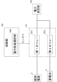
- FIG. 2 is a block diagram illustrating in detail the relay included in the charging device according to the first embodiment.
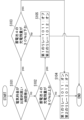
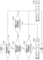
- FIG. 3 is a flowchart for explaining a mechanism by which the charging device according to the first embodiment switches the supply source of AC power.
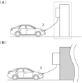
- Fig. 4A is a schematic diagram showing a state in which power is supplied to an EV from a charging facility (pole) that houses a power switching module provided in a charging device according to Example 1.
- Fig. 4B is a diagram showing a state in which the power switching module according to the embodiment is installed on a wall.
- FIG. 4A is a schematic diagram showing a state in which power is supplied to an EV from a charging facility (pole) that houses a power switching module provided in a charging device according to Example 1.
- Fig. 4B is a diagram showing a state in which the power switching module according to the embodiment is installed on a
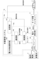
- FIG. 5 is a block diagram illustrating an example in which the charging device according to the second embodiment is applied to charging an EV.
- FIG. 6 is a flowchart for explaining a mechanism by which the charging device according to the second embodiment switches the supply source of AC power.
- FIG. 7 is a flowchart for supplementarily explaining the flow shown in FIG.
- Fig. 1 is a block diagram showing an example in which a charging device 1 according to this application example is applied to charging an EV 2.
- the charging device 1 according to this application example is configured to include a power switching module 10, which is a module involved in managing charging power in the charging device.
- the power switching module 10 is configured to include a control unit 100, a relay 101, a power measurement unit 102, a storage unit 103, and a communication unit 104.
- the power switching module 10 is connected to two power sources, a commercial power source 3 and a storage battery 4, and a relay 101 opens and closes the power lines to which the commercial power source 3 and the storage battery 4 are each connected.
- the storage battery 4 is installed for home use, and stores electrical energy converted from solar energy by a solar panel installed on the roof of a house, for example. In other words, since the storage battery 4 is charged using power generated by the solar panel, the cost of using the electrical energy stored in the storage battery 4 is relatively low.
- Relay 101 receives a command signal from control unit 100 and switches the power lines to which the two power sources are connected from on (closed state) to off (open state) or from off (open state) to on (closed state).
- relay 101 receives an on command signal and AC current is input from commercial power source 3 or storage battery 4, the AC current is output to EV charging outlet 11 via power measurement unit 102, which measures power. This makes it possible to charge EV 2 by connecting the charging cable of EV 2 to EV charging outlet 11.
- the state in which power is supplied from power switching module 10 to EV 2 is shown in Figure 4A, which will be described later.
- the relay 101 is configured to include two relays, a first relay 1011 and a second relay 1012, where the first relay 10111 opens and closes the power line connected to the commercial power source 3, and the second relay 1012 opens and closes the power line connected to the storage battery 4.
- FIG. 2 shows the power lines from each of the two power sources to the power measurement unit 102.
- the control unit 100 outputs an ON command signal to the first relay 1011 and an OFF command signal to the second relay 1012, thereby making the commercial power source 3 the supply source of AC power.
- the control unit 100 also has a power supply selection unit 1001 that selects a power source that supplies power to the EV 2.
- the power supply selection unit 1001 selects one of two power sources, the commercial power source 3 or the storage battery 4, as the source of AC power supply, but hereinafter, it will be described as the control unit 100 being the entity that selects one of the two power sources.
- the charging device 1 includes a memory unit 103, which can store the relationship between the electricity fee and the time in advance. This relationship may be saved as a table. Based on the data stored in the memory unit 103, the control unit 100 outputs an OFF command signal to the first relay 1011 and an ON command signal to the second relay 1012 during a time period in which the electricity fee is higher than a predetermined fee as a threshold (hereinafter also referred to as a time period in which the electricity fee is relatively high), even if the commercial power source 3 is operating normally.
- a predetermined fee as a threshold hereinafter also referred to as a time period in which the electricity fee is relatively high
- the storage battery 4 becomes the AC power supply source, and as described above, the cost of using the electrical energy stored in the storage battery 4 is relatively low, so that the electricity fee charged to the user is relatively low.
- the control unit 100 when the commercial power source 3 is operating normally and the time period is one in which the electricity rate is equal to or lower than a predetermined rate (hereinafter, also referred to as a time period in which the electricity rate is relatively low), the control unit 100 outputs an ON command signal to the first relay 1011 and outputs an OFF command signal to the second relay 1012. This also makes the commercial power source 3 the source of AC power supply, making it possible to reduce the electricity charges imposed on the user.
- the power switching module 10 has a wireless communication function by the communication unit 104 in addition to the function of opening and closing the power line by the first relay 1011 and the second relay 1012 described above.
- the communication unit 104 transmits information necessary for charging management to the charging management system 12 built on the cloud via a network (not shown) using a wireless communication function.
- the communication unit 104 also receives instructions from the charging management system 12 using the wireless communication function and transmits the instructions to the control unit 100. Based on this, the control unit 100 outputs a command signal for opening and closing control to the first relay 1011 and the second relay 1012. For example, when the charging cable of the EV2 is connected to the EV charging outlet 11, it is also possible for the user to specify the time to start charging by operating a terminal such as a smartphone rather than starting charging immediately.
- the control unit 100 receives an instruction from the charging management system 12 via the communication unit 104 and outputs an ON command signal to the first relay 1011 or the second relay 1012 in accordance with the instruction.
- the communication unit 104 then transmits to the charging management system 12 information such as the electricity fee related to charging the EV2 based on the power measured by the power measurement unit 102 and the relationship between the electricity fee and time stored in the memory unit 103. It is also possible to specify the time to end charging in the same manner.
- the control unit 100 outputs a command signal for opening and closing control to the first relay 1011 and the second relay 1012 based on the remaining charge of the storage battery 4 in addition to the relationship between the electricity rate and the time stored in the memory unit 103 described above.
- a predetermined remaining amount is set as a threshold value for the remaining charge of the storage battery 4
- the control unit 100 determines whether the remaining charge of the storage battery 4 is high or low based on this predetermined remaining amount, and can switch to charging from the storage battery 4 when the remaining charge of the storage battery 4 is high, and to charging from the commercial power source 3 when the remaining charge of the storage battery 4 is low. This makes it possible to balance and suppress both the increase in the electricity rate imposed on the user and the consumption of the power stored in the storage battery 4.
- the control of the control unit 100 based on the remaining charge of the storage battery 4 will be described in detail using the flowchart shown in FIG. 3 below.
- the power switching module 10 is configured with a control unit 100, a first relay 1011, a second relay 1012, a memory unit 103, and a communication unit 104, it can be handled independently of the charging device 1. This makes it possible to apply the power switching module 10 to systems other than the charging device 1, and to sell and provide the power switching module 10 on its own.
- the battery of EV2 is shown as an example of the object to be charged, but the object to be charged in this disclosure is not limited to this, and may be, for example, other electric vehicles such as an electrically assisted bicycle, an electric kick scooter, an electric wheelchair, and a robotic lawnmower. Furthermore, rechargeable electrical products other than electric vehicles may also be the object to be charged.
- step S101 it is determined whether or not the time period during which the EV 2 is being charged is a time period during which the electricity rate is relatively high, based on the relationship between the electricity rate and time stored in the memory unit 103. If the control unit 100 determines that the time period during which the electricity rate is relatively low (step S101: no), then in step S102, it outputs a command signal for opening and closing control to the first relay 1011 and the second relay 1012, based on the remaining charge of the storage battery 4.
- step S102 since this is a time period when electricity rates are relatively low, in principle the control unit 100 outputs an ON command signal to the first relay 1011 and an OFF command signal to the second relay 1012, thereby making the commercial power source 3 the source of AC power.
- the control unit 100 preferentially makes the storage battery 4 the source of AC power. Specifically, the control unit 100 obtains the remaining charge of the storage battery 4 and compares this remaining charge with a predetermined remaining charge to determine whether the remaining charge of the storage battery 4 is high.
- the predetermined remaining amount is set to 90%, and if the control unit 100 determines that the remaining charge of the storage battery 4 is less than 90% (step S102: no), as a rule, in step S104, it outputs an ON command signal to the first relay 1011 and an OFF command signal to the second relay 1012, thereby setting the source of AC power as the commercial power source 3.
- the control unit 100 determines that the remaining charge of the storage battery 4 is 90% or more (step S102: yes)
- it determines that the remaining charge of the storage battery 4 is high, and exceptionally, in step S105, it outputs an OFF command signal to the first relay 1011 and an ON command signal to the second relay 1012, thereby setting the source of AC power as the storage battery 4.
- step S103 it outputs a command signal for opening and closing control to the first relay 1011 and the second relay 1012 based on the remaining charge of the storage battery 4.
- the control unit 100 outputs an OFF command signal to the first relay 1011 and an ON command signal to the second relay 1012, thereby making the storage battery 4 the supply source of AC power.
- the commercial power source 3 is preferentially made the supply source of AC power as long as the commercial power source 3 is operating normally.
- the control unit 100 obtains the remaining charge of the storage battery 4 and compares the remaining charge with a second predetermined remaining charge as a threshold value to determine whether the remaining charge of the storage battery 4 is low.
- the second predetermined remaining amount is set to 30%, and when the control unit 100 determines that the remaining charge of the storage battery 4 is higher than 30% (step S103: no), it outputs an OFF command signal to the first relay 1011 and an ON command signal to the second relay 1012 in step S105 as a rule, thereby setting the storage battery 4 as the source of AC power.
- the control unit 100 determines that the remaining charge of the storage battery 4 is 30% or less (step S103: yes)
- it exceptionally outputs an ON command signal to the first relay 1011 and an OFF command signal to the second relay 1012 in step S104 setting the commercial power source 3 as the source of AC power, assuming that the remaining charge of the storage battery 4 is low.
- the second predetermined remaining amount is a value lower than the predetermined remaining amount, the values of the predetermined remaining amount and the second predetermined remaining amount are not limited to 90% and 30%, respectively.
- control unit 100 may switch the AC power supply source without considering the remaining charge of the storage battery 4. That is, in the flowchart shown in FIG. 3, the processes of steps S102 and S103 do not necessarily have to be considered. In this case, if the control unit 100 determines that the current time period is a relatively low electricity rate (step S101: no), in step S104, the control unit 100 outputs an ON command signal to the first relay 1011 and an OFF command signal to the second relay 1012, thereby setting the AC power supply source to the commercial power source 3.
- step S101 determines that the current time period is a relatively high electricity rate (step S101: yes)
- step S105 the control unit 100 outputs an OFF command signal to the first relay 1011 and an ON command signal to the second relay 1012, thereby setting the AC power supply source to the storage battery 4.
- FIG. 4A is a schematic diagram showing a state in which power is supplied to an EV 2 from a charging facility (pole) that houses a power switching module 10 provided in a charging device 1 according to this embodiment.
- a charging facility pole
- a power switching module 10 provided in a charging device 1 according to this embodiment.
- This charging method corresponds to basic charging, which charges the EV 2 during a time period when the EV 2 is not in use, and since it is possible to charge the EV 2 over a long period of time, it is possible to reduce the load on the battery of the EV 2.
- each person connects a cord to an EV charging outlet 11 to charge the EV 2, it is possible to charge the EV 2 only when necessary.
- the installation cost of the power switching module 10 for basic charging is relatively low.
- the power switching module 10 itself does not need to be waterproof or weatherproof.
- basic charging is exemplified as the charging method, but it is possible to introduce the power switching module 10 and supply power to the EV 2 using other charging methods.
- Other charging methods include destination charging, in which charging is performed at a facility at the destination, and route charging, in which charging is performed on the way to the destination.
- the location where the power switching module 10 is mounted is not limited to the inside of a pole, and it may be stored inside a wall-mounted pool box and installed on a wall as shown in FIG. 4B. In this way, by expanding the location where the power switching module 10 is mounted, it is possible to increase the penetration rate of the power switching module 10, and it becomes possible to apply the charging device 1 in many areas.
- Example 2 Next, an example in which the charging device 1a according to the second embodiment of the present disclosure is applied to charging an EV 2 will be described with reference to Fig. 5.
- the charging device 1a has many components in common with the charging device 1 of the first embodiment, and therefore such components are denoted by the same reference numerals and will not be described again.
- the relay 101 includes two relays, a first relay 1011 and a second relay 1012, as shown in Fig. 2.
- a charging management system 12a constructed on the cloud is configured to include a power supply selection unit 1001 and a storage unit 103. That is, since the control unit 100 in the power switching module 10a does not include the power supply selection unit 1001, it is possible to reduce the control load. In addition, since the storage unit 103 is provided in the charging management system 12a on the cloud, it is possible to reduce the management and maintenance load of the power switching module 10a. That is, the control unit 100 is provided with information on the relationship between the electricity price and the time stored in the storage unit 103 on the cloud, and can easily execute the opening and closing control of the first relay 1011 and the second relay 1012.
- the power measured by the power measurement unit 102 can be used as a criterion for determining whether the commercial power source 3 is operating normally. For example, if the commercial power source 3 experiences a power outage due to a disaster such as an earthquake, the power measurement unit 102 will be unable to measure the power of the AC current input from the commercial power source 3, and it will be possible to determine that the commercial power source 3 is not operating normally. Even when AC power is input from the commercial power source 3, the power measured by the power measurement unit 102 may be lower than normal.
- a preset value is set for the power measured by the power measurement unit 102, and if the measured power is less than the preset value, it is possible to determine that the commercial power source 3 is not operating normally.
- the control unit 100 outputs a command signal to the first relay 1011 and the second relay 1012 based on the measured power, and if the measured power is less than the preset value, it determines that the commercial power source 3 is not operating normally, and outputs an OFF command signal to the first relay 1011 and an ON command signal to the second relay 1012. This switches the AC power supply source from the commercial power source 3 to the storage battery 4. This makes it possible to charge the EV 2 even if the commercial power source 3 experiences a power outage during a disaster or the like.
- the control unit 100 first determines whether the commercial power source 3 is experiencing a power outage in step S106. Specifically, as described above, the control unit 100 may obtain the power measured by the power measurement unit 102 and compare the power with a preset value to determine whether the commercial power source 3 is experiencing a power outage. If the measured power is equal to or greater than the preset value, the control unit 100 determines that the commercial power source 3 is not experiencing a power outage (step S106: no), and then in step S101, determines whether the time period during which the EV 2 is being charged is a time period during which the electricity rate is relatively high, based on the relationship between the electricity rate and the time stored in the storage unit 103.
- the power of the commercial power source 3 is compared with a preset value before comparing the electricity rate with a predetermined rate.
- the control unit 100 determines that the commercial power source 3 is experiencing a power outage (step S106: yes), and in step S105 outputs an OFF command signal to the first relay 1011 and an ON command signal to the second relay 1012, thereby making the storage battery 4 the supply source of AC power. This not only keeps the electricity fee required for charging relatively low, but also makes it possible to charge from the storage battery 4 even in an emergency such as a disaster.
- step S106 determines whether the commercial power source 3 is out of power (i.e., step S106: yes)
- step S105 the storage battery 4 is set as the supply source of AC power
- step S103 the control unit 100 determines whether the remaining charge of the storage battery 4 is 30% or less, which corresponds to the third predetermined remaining charge in this disclosure.
- step S103 determines that the remaining charge of the storage battery 4 is more than 30% (step S103: no)
- the control unit 100 continues the state in step S105 in step S107.
- step S103 when the control unit 100 determines that the remaining charge of the storage battery 4 is 30% or less (step S103: yes), the control unit 100 exceptionally outputs an OFF command signal to both the first relay 1011 and the second relay 1012, and stops charging the battery of the EV2, because the commercial power source 3 is out of power and the remaining charge of the storage battery 4 is low. This prevents the charge level of the storage battery 4 from decreasing excessively.
- the relay unit includes a first relay (1011) that opens and closes a power line connected to a commercial power source (3) and a second relay (1012) that opens and closes a power line connected to a storage battery (4),
- the power supply selection unit is selecting the commercial power source as a power supply source for supplying power to the battery during a time period when the hourly electricity rate of the commercial power source is equal to or lower than a predetermined rate;
- the charging device described in appendix 1 characterized in that the storage battery is selected as the power supply source for supplying power to the battery during a time period when the hourly electricity rate of the commercial power source is higher than the specified rate.
- the power supply selection unit is 3. The charging device according to claim 2, wherein the storage battery is selected as a power supply source for supplying power to the battery.
- the power supply selection unit is The charging device according to claim 5, wherein the control unit does not select a power supply source to supply power to the battery, and does not supply power to the battery.
- [Appendix 8] 3. The charging device according to claim 2, wherein power for driving the control unit is secured from the storage battery.
Landscapes
- Engineering & Computer Science (AREA)
- Power Engineering (AREA)
- Transportation (AREA)
- Mechanical Engineering (AREA)
- Charge And Discharge Circuits For Batteries Or The Like (AREA)
- Electric Propulsion And Braking For Vehicles (AREA)
Abstract
電動移動体のバッテリーを充電するための充電装置は、リレー部と、リレー部における各々のリレーに対して、開指令または閉指令を送ることで、複数の電力供給源の何れかから、バッテリーへの電力供給を可能とする制御部と、を備え、制御部は、バッテリーへの電力の充電時における、複数の電力供給源の少なくとも一つの状態に基づいて、バッテリーに電力供給する電力供給源を選択する、電力供給選択部を有する。
Description
本発明は、電動移動体に充電する際の電力供給源を複数の種類の電力供給源の中から切り替えることが可能な充電装置に関する。
従来、電気機器や電気自動車(Electric Vehicle:EV)等の負荷に電力を供給し、当該負荷を充電するためのシステムが公知である。当該システムにおいては、通常時は商用電源から負荷に電力が供給され、例えば災害等の非常時において商用電源が停電した場合には、非常用電源から負荷に電力が供給される。これによって、非常時においても負荷を充電することが可能となる(例えば、特許文献1乃至3参照)。
また、近年では、EVの普及に向けて、例えば駐車場といった普段EVが長時間滞在する場所で充電する基礎充電の整備が進められている。EVを充電する際には、上記の通り、通常時は商用電源からEVに電力が供給されるが、商用電源から電力が供給されることによってユーザに課される電気料金は、一般的に時間帯によって変動する。すなわち、充電に係る電気料金が比較的高くなる時間帯があり、そのような時間帯においては、商用電源が正常に稼働している場合であっても、ユーザに課される電気料金が比較的安くなるように、電力の供給元となる電力供給源が商用電源から商用電源以外のものに自動的に切り替わることが望ましい。このように、電力供給源に関わる状態によって、電力供給源を選択可能とすることに対する要望が高まっている。
本件開示の技術は、上記の問題を解決するためになされたものであり、その目的は、電動移動体のバッテリーの充電のための充電装置において、複数の電力供給源の状態に応じて、最適な電力供給源を選択可能な技術を提供することである。
上記の課題を解決するための本開示は、電動移動体のバッテリーを充電するための充電装置であって、
複数の電力供給源に各々接続された複数のリレーを含む、リレー部と、
前記リレー部における各々のリレーに対して、開指令または閉指令を送ることで、前記複数の電力供給源の何れかから、前記バッテリーへの電力供給を可能とする制御部と、
を備え、
前記制御部は、
前記バッテリーへの電力の充電時における、前記複数の電力供給源の少なくとも一つの状態に基づいて、前記バッテリーに電力供給する電力供給源を選択する、電力供給選択部を有することを特徴とする、充電装置を含む。
複数の電力供給源に各々接続された複数のリレーを含む、リレー部と、
前記リレー部における各々のリレーに対して、開指令または閉指令を送ることで、前記複数の電力供給源の何れかから、前記バッテリーへの電力供給を可能とする制御部と、
を備え、
前記制御部は、
前記バッテリーへの電力の充電時における、前記複数の電力供給源の少なくとも一つの状態に基づいて、前記バッテリーに電力供給する電力供給源を選択する、電力供給選択部を有することを特徴とする、充電装置を含む。
本開示においては、充電装置に搭載された電力開閉モジュールが、例えば商用電源と蓄電池の二つの電源に接続されている。そして、リレー部は、例えば第1のリレーと第2のリレーの二つのリレーを含んで構成され、制御部は、二つの電源の各々が接続された第1のリレー及び第2のリレーに指令信号を出力し、各々のリレーが電源に接続された電力線をオン(閉状態)からオフ(開状態)、またはオフ(開状態)からオン(閉状態)の状態に切り替える制御を実施する。本開示における充電装置を用いることによって、制御部を稼働させ、第1のリレー及び第2のリレーの各々による電力線の開閉状態を制御することによって、交流電力の供給源を商用電源または蓄電池のいずれかに切り替えることが可能である。これによって、複数の電力供給源の中から最適なものを選択し、良好なコストで充電することが可能となる。また、電力供給源の切り替えは、電力供給選択部によって、電力供給源の状態に基づいて、自動的に行われるため、電力線の再配置や、コンセント出力への充電ケーブルの再接続といった人為的なコストを省くことが可能になる。
また、本開示においては、前記リレー部は、商用電源と接続された電力線を開閉する第1のリレーと、蓄電池と接続された電力線を開閉する第2のリレーと、を含み、前記電力供給選択部は、前記商用電源における、時間あたりの電気料金が所定料金以下の時間帯には、前記バッテリーに電力供給する電力供給源として、前記商用電源を選択し、前記商用電源における、時間あたりの電気料金が、前記所定料金より高い時間帯には、前記バッテリーに電力供給する電力供給源として、前記蓄電池を選択することとしてもよい。
本開示においては、蓄電池は、例えば、住宅等の屋根に設置されたソーラーパネルによって太陽光エネルギー等の自然エネルギーから変換された電気エネルギーを蓄電してもよい。すなわち、蓄電池は自然エネルギーを起源として充電しているため、蓄電池に蓄電された電気エネルギーの使用に係るコストは比較的低い。
ここで、商用電源を交流電力の供給源とした際の充電に課される電気料金は、一般的に、時間帯によって異なる。この電気料金に基づき、電力供給選択部は、電気料金が所定料金より高くなる時間帯である場合は、商用電源が正常に稼働している場合であっても、電力供給源として蓄電池を選択する。これによって、交流電力の供給源が蓄電池に切り替わり、既述の通り、蓄電池に蓄電された電気エネルギーの使用に係るコストは比較的低いため、ユーザに課される電気料金が比較的安くなる。対して、電力供給選択部は、商用電源が正常に稼働しており、かつ、電気料金が所定料金以下となる時間帯である場合は、電力供給源として商用電源を選択する。これによって、交流電力の供給源が商用電源に切り替わり、蓄電池に蓄電された電力を節電することが可能となる。
また、本開示においては、前記商用電源における、時刻と時間あたりの電気料金との関係の情報を格納した記憶部をさらに備え、前記電力供給選択部は、前記記憶部から読み出した、前記時刻と時間あたりの電気料金との関係の情報に基づいて、前記バッテリーに電力供給する電力供給源を選択することとしてもよい。これによって、電力供給選択部は、電気料金に基づいて、より適切に電力供給源を選択することが可能となる。
また、本開示においては、前記蓄電池の充電残量が所定残量より高い場合は、前記電力供給選択部は、前記商用電源における、前記時間あたりの電気料金が、前記所定料金以下の時間帯であっても、前記バッテリーに電力供給する電力供給源として、前記蓄電池を選択することとしてもよい。本開示においては、蓄電池の充電残量に所定残量という指標を設け、電力供給選択部は、この所定残量に基づいて、蓄電池の充電残量が多いか否か判断し、蓄電池の充電残量が多い場合には蓄電池からの充電に切り替えることが可能である。なお、本開示においては、記憶部に記憶された電気料金が所定料金以下となる時間帯である場合、原則的には商用電源からの充電に切り替えられるが、蓄電池の充電残量が多い場合には優先的に蓄電池からの充電に切り替えることとしている。これによって、蓄電池が満充電の状態となることをより確実に抑制することが可能となる。
また、本開示においては、前記蓄電池の充電残量が、所定残量より低い第2所定残量以下の場合は、前記電力供給選択部は、前記商用電源における、前記時間あたりの電気料金が、前記所定料金より高い時間帯であっても、前記バッテリーに電力供給する電力供給源として、前記商用電源を選択することとしてもよい。すなわち、原則的には蓄電池からの充電に切り替えられる場合であっても、電力供給選択部は、蓄電池の充電残量が少ないと判断した場合には、商用電源が正常に稼働している限り、優先的に商用電源からの充電に切り替えることとしてもよい。これによって、蓄電池の充電量が過度に低下することを抑制できる。
また、本開示においては、前記商用電源の停電時は、前記電力供給選択部は、前記バッテリーに電力供給する電力供給源として、前記蓄電池を選択することとしてもよい。ここで、充電装置の不使用時には、第1のリレー及び第2のリレーは共にオフの状態となり、交流電力の入力が完全に遮断される。また、通常時に充電装置を使用する際には、第1のリレーはオンの状態となり、第2のリレーはオフの状態になる。すなわち、通常時は商用電源からのみ交流電力が入力され、電動移動体は商用電源からの電力で充電されることとなる。
しかしながら、例えば、地震等の災害や設備トラブルによって、商用電源が停電することがある。例えば、電力測定部が測定する電力に対して既定値を設け、電力を規定値と比較して、電力が規定値未満である場合、電力供給選択部は、商用電源が停電していると判断し、交流電力の供給元を、商用電源から蓄電池に切り替えるようにしてもよい。これによって、災害時等において商用電源が停電した場合であっても、蓄電池から電動移動体に充電することが可能である。
また、本開示においては、前記商用電源の停電時において、前記蓄電池の充電残量が第3所定残量以下の場合は、前記電力供給選択部は、前記バッテリーに電力供給する電力供給源を選択せず、前記制御部は、前記バッテリーへの電力供給を行わないこととしてもよい。すなわち、商用電源が停電しており、かつ、蓄電池の充電残量が少ない場合には、制御部は、例外的に、第1のリレー及び第2のリレーの双方にオフの指令信号を出力することとしてもよい。これによって、停電時に、蓄電池の充電量も無くなるような状況の発生を抑制することが可能である。
また、本開示においては、前記制御部の駆動用の電力は前記蓄電池から確保することとしてもよい。これによって、停電時においても、充電装置の作動を確保することが可能である。
また、本開示においては、クラウド上のサーバ装置と通信可能な通信部をさらに備え、前記電力供給選択部は前記サーバ装置上に設置され、前記制御部は、前記通信部で受信した前記サーバ装置からの信号に基づいて、前記リレー部における各々のリレーに対して開指令または閉指令を送ることとしてもよい。
また、本開示においては、前記リレー部と、前記制御部における少なくとも前記電力供給選択部以外の部分と、前記リレー部を通じて前記バッテリーに供給される電力を測定する電力測定部と、クラウド上のサーバ装置と通信可能な通信部と、がモジュール化され、前記電動移動体のために設置された充電用設備に収納され、前記クラウド上の前記サーバ装置に前記通信部を介して、前記電力測定部が測定した電力に関する情報を送信可能であるとともに、前記クラウド上の前記サーバ装置から前記通信部を介して、前記バッテリーへの電力供給に関する情報を受信可能としたこととしてもよい。これによれば、充電装置において重要な構成要素を一体として扱うことができ、装置の構築や故障対応をより容易に行うことが可能になる。また、当該モジュールを、本開示における充電装置以外の他のシステムに適用することや、当該モジュールを単体で流通させることが可能となる。
なお、本開示においては、上記のモジュールは、例えば集合住宅の駐車場等、基礎充電をすることが可能な場所に設置された充電設備に収納されていることを想定している。そして、当該モジュールを例えば電動移動体の充電に適用し、充電装置を用いることによって、電動移動体がユーザの意図通りに充電されることを可能とする。ここで、電動移動体には、EVの他、電動アシスト自転車、電動キックボード、電動車いす、及びロボット芝刈り機等も含まれる。
なお、上記の課題を解決するための手段は、可能な限り互いに組み合わせて用いることができる。
本件開示の技術によれば、電動移動体のバッテリーの充電のための充電装置において、複数の電力供給源の状態に応じて、最適な電力供給源を選択することが可能である。
〔適用例〕
以下に本開示の適用例の概要について一部の図面を用いて説明する。図1は、本適用例に係る充電装置1をEV2の充電に適用する例を概略的に示すブロック図である。本適用例に係る充電装置1は、充電装置中の充電電力の管理に関わるモジュールである電力開閉モジュール10を含んで構成される。電力開閉モジュール10は、制御部100、リレー101、電力測定部102、記憶部103、及び通信部104等を備えて構成される。
以下に本開示の適用例の概要について一部の図面を用いて説明する。図1は、本適用例に係る充電装置1をEV2の充電に適用する例を概略的に示すブロック図である。本適用例に係る充電装置1は、充電装置中の充電電力の管理に関わるモジュールである電力開閉モジュール10を含んで構成される。電力開閉モジュール10は、制御部100、リレー101、電力測定部102、記憶部103、及び通信部104等を備えて構成される。
電力開閉モジュール10は、商用電源3と蓄電池4の二つの電源に接続されており、リレー101は、商用電源3及び蓄電池4の各々が接続された電力線を開閉する。蓄電池4は、家庭用のものとして設置され、例えば、住宅等の屋根に設置されたソーラーパネルによって太陽光エネルギーから変換された電気エネルギーを蓄電する。すなわち、蓄電池4はソーラーパネルで発電された電力を用いて充電しているため、蓄電池4に蓄電された電気エネルギーの使用に係るコストは比較的低い。
リレー101は、制御部100からの指令信号を受けて、二つの電源の各々が接続された電力線を、オン(閉状態)からオフ(開状態)、またはオフ(開状態)からオン(閉状態)の状態に切り替える。リレー101がオンの指令信号を受けた状態で、商用電源3または蓄電池4から交流電流が入力されると、その交流電流は、電力を測定する電力測定部102を介して、EV充電コンセント11に出力される。これによって、EV2の充電ケーブルをEV充電コンセント11に接続することで、EV2の充電が可能となる。なお、電力開閉モジュール10からEV2に電力を供給する様子については、後述の図4Aに示す。
より詳細には、図2に示す様に、リレー101は、第1のリレー1011と第2のリレー1012の二つのリレーを含んで構成され、第1のリレー10111は商用電源3に、第2のリレー1012は蓄電池4に接続された電力線を開閉する。なお、図2は、二つの電源の各々から電力測定部102までの電力線を示している。本適用例においては、通常時には、制御部100は、第1のリレー1011にオンの指令信号を出力し、第2のリレー1012にオフの指令信号を出力することによって、交流電力の供給源を商用電源3とする。
また、制御部100は、EV2に電力を供給する電源を選択する電力供給選択部1001を有する。本適用例において、より正確には、電力供給選択部1001が交流電力の供給源として商用電源3または蓄電池4の二つの電源のいずれかを選択するが、以下、二つの電源のいずれかを選択する主体は制御部100であるものとして記載する。
図1の説明に戻る。商用電源3を交流電力の供給源とした際の充電に課される電気料金は、一般的に時間帯によって異なる。充電装置1は、記憶部103を備え、記憶部103には、電気料金と時刻の関係を予め記憶させることが可能である。なおこの関係は、テーブルとして保存するようにしてもよい。記憶部103に記憶されたデータに基づき、制御部100は、電気料金が閾値としての所定料金より高くなる時間帯(以下、電気料金が比較的高い時間帯ともいう)である場合は、商用電源3が正常に稼働している場合であっても、第1のリレー1011にオフの指令信号を出力し、第2のリレー1012にオンの指令信号を出力する。これによって、交流電力の供給源が蓄電池4となり、既述の通り、蓄電池4に蓄電された電気エネルギーの使用に係るコストは比較的低いため、ユーザに課される電気料金が比較的安くなる。対して、制御部100は商用電源3が正常に稼働しており、かつ、電気料金が所定料金以下となる時間帯(以下、電気料金が比較的安い時間帯ともいう)である場合は、第1のリレー1011にオンの指令信号を出力し、第2のリレー1012にオフの指令信号を出力する。これによっても交流電力の供給源が商用電源3となり、ユーザに課される電気料金を低減することが可能となる。
〔実施例1〕
以下、本開示の実施例1に係る充電装置1について、図面(上記の適用例で一旦説明した図面も含む)を用いてより詳細に説明する。なお、本開示の実施例に係る充電装置1は、以下の構成に限定する趣旨のものではない。
以下、本開示の実施例1に係る充電装置1について、図面(上記の適用例で一旦説明した図面も含む)を用いてより詳細に説明する。なお、本開示の実施例に係る充電装置1は、以下の構成に限定する趣旨のものではない。
<構成>
図1及び図2について、本実施例に係る電力開閉モジュール10は、既述の第1のリレー1011及び第2のリレー1012による電力線を開閉する機能の他、通信部104による無線通信機能を有する。
図1及び図2について、本実施例に係る電力開閉モジュール10は、既述の第1のリレー1011及び第2のリレー1012による電力線を開閉する機能の他、通信部104による無線通信機能を有する。
通信部104は、無線通信機能を用いて、クラウド上に構築された充電管理システム12に対し、ネットワーク(不図示)を介して充電管理に必要な情報を送信する。また、通信部104は、無線通信機能を用いて充電管理システム12からの指示を受信し、当該指示を制御部100に伝達する。これに基づき、制御部100は第1のリレー1011及び第2のリレー1012に開閉制御のための指令信号を出力する。例えば、EV2の充電ケーブルをEV充電コンセント11に接続した際、すぐに充電を開始せず、ユーザがスマートフォン等の端末を操作することにより、充電を開始する時間を指定することも可能である。このとき、指定した時間の情報は充電管理システム12において記憶され、指定した時間に達すると、制御部100は通信部104を介して充電管理システム12からの指示を受信し、当該指示に応じて第1のリレー1011または第2のリレー1012にオンの指令信号を出力する。そして通信部104は、充電管理システム12に対し、電力測定部102によって測定された電力や記憶部103に記憶された電気料金と時間の関係に基づき、EV2の充電に係る電気料金等の情報を送信する。また、充電を終了する時間についても同様に指定することが可能である。
また、制御部100は、既述の記憶部103に記憶された電気料金と時刻の関係に加えて、蓄電池4の充電残量に基づいて第1のリレー1011及び第2のリレー1012に開閉制御のための指令信号を出力する。本実施例においては、蓄電池4の充電残量に閾値として所定残量を設け、制御部100は、この所定残量に基づいて蓄電池4の充電残量が多いまたは少ないと判断し、蓄電池4の充電残量が多い場合には蓄電池4からの充電に、蓄電池4の充電残量が少ない場合には商用電源3からの充電に切り替えることが可能である。これによって、ユーザに課される電気料金の上昇と蓄電池4に蓄電された電力の消費の双方を均衡して抑制することが可能となる。なお、蓄電池4の充電残量に基づく制御部100の制御について、詳細は後述の図3に示すフローチャートを用いて説明する。
また電力開閉モジュール10は、制御部100、第1のリレー1011、第2のリレー1012、記憶部103、及び通信部104等を備えて構成されているため、充電装置1から独立して扱うことが可能である。これによって、電力開閉モジュール10を充電装置1以外の他のシステムに適用することや、電力開閉モジュール10を単体で販売提供することが可能となる。
なお、本実施例においては充電の対象としてEV2のバッテリーを例示しているが、本開示の充電の対象はこれに限らず、例えば、電動アシスト自転車、電動キックボード、電動車いす、及びロボット芝刈り機等、他の電動移動体であってもよい。さらに、電動移動体以外の充電式の電気製品を充電の対象としてもよい。
<フローチャート>
次に図3を用いて、本実施例に係る充電装置1が交流電力の供給源を切り替える仕組みについて説明する。図2に示すフローチャートについて、まずステップS101において、記憶部103に記憶された電気料金と時間の関係に基づき、EV2を充電している時間帯が、電気料金が比較的高い時間帯であるか否かを判断する。制御部100は、電気料金が比較的安い時間帯であると判断した場合(ステップS101:no)、次にステップS102において、蓄電池4の充電残量に基づいて第1のリレー1011及び第2のリレー1012に開閉制御のための指令信号を出力する。
次に図3を用いて、本実施例に係る充電装置1が交流電力の供給源を切り替える仕組みについて説明する。図2に示すフローチャートについて、まずステップS101において、記憶部103に記憶された電気料金と時間の関係に基づき、EV2を充電している時間帯が、電気料金が比較的高い時間帯であるか否かを判断する。制御部100は、電気料金が比較的安い時間帯であると判断した場合(ステップS101:no)、次にステップS102において、蓄電池4の充電残量に基づいて第1のリレー1011及び第2のリレー1012に開閉制御のための指令信号を出力する。
ここで、ステップS102の段階においては電気料金が比較的安い時間帯であるため、原則的には制御部100は第1のリレー1011にオンの指令信号を出力し、第2のリレー1012にオフの指令信号を出力することによって、交流電力の供給源を商用電源3とする。しかしながら同段階において、本実施例においては、蓄電池4の充電残量が多い場合には優先的に交流電力の供給源を蓄電池4とする。具体的には、制御部100は蓄電池4の充電残量を取得し、その充電残量を所定残量と比較して蓄電池4の充電残量が多いか否かを判断する。
ここで本実施例においては所定残量を90%とし、制御部100は蓄電池4の充電残量が90%未満である場合と判断した場合(ステップS102:no)、原則通り、ステップS104において第1のリレー1011にオンの指令信号を出力し、第2のリレー1012にオフの指令信号を出力することによって、交流電力の供給元を商用電源3とする。対して制御部100は、蓄電池4の充電残量が90%以上である場合と判断した場合(ステップS102:yes)、蓄電池4の充電残量が多いと判断したとして、例外的にステップS105において、第1のリレー1011にオフの指令信号を出力し、第2のリレー1012にオンの指令信号を出力することによって、交流電力の供給元を蓄電池4とする。これによってステップS104においては、蓄電池4に蓄電された電力の消費を抑制することが可能となり、ステップS105においては、ユーザに課される電気料金の上昇を抑制することが可能となる。
また制御部100は、電気料金が比較的高い時間帯であると判断した場合(ステップS101:yes)、次にステップS103において、蓄電池4の充電残量に基づいて、第1のリレー1011及び第2のリレー1012に開閉制御のための指令信号を出力する。ここでステップS103の段階においては、電気料金が比較的高い時間帯であるため、原則的には制御部100は、第1のリレー1011にオフの指令信号を出力し、第2のリレー1012にオンの指令信号を出力することによって、交流電力の供給源を蓄電池4とする。しかしながら同段階において、本実施例においては、蓄電池4の充電残量が少ない場合には、商用電源3が正常に稼働している限り優先的に交流電力の供給源を商用電源3とする。具体的には、制御部100は蓄電池4の充電残量を取得し、その充電残量を閾値としての第2所定残量と比較して蓄電池4の充電残量が少ないか否かを判断する。
ここで本実施例においては、第2所定残量を30%とし、制御部100は、蓄電池4の充電残量が30%より高い場合と判断した場合(ステップS103:no)、原則通りステップS105において第1のリレー1011にオフの指令信号を出力し、第2のリレー1012にオンの指令信号を出力することによって、交流電力の供給源を蓄電池4とする。対して制御部100は、蓄電池4の充電残量が30%以下である場合と判断した場合(ステップS103:yes)、蓄電池4の充電残量が少ないと判断したとして、例外的にステップS104において第1のリレー1011にオンの指令信号を出力し、第2のリレー1012にオフの指令信号を出力することによって、交流電力の供給源を商用電源3とする。なお、第2所定残量が所定残量より低い値であれば、所定残量、及び第2所定残量の値は各々、90%、及び30%に限らない。
また本実施例においては、制御部100は蓄電池4の充電残量を考慮せずに、交流電力の供給源を切り替えてもよい。すなわち、図3に示すフローチャートにおいて、ステップS102及びステップS103の工程を必ずしも考慮しなくてよい。この場合、制御部100は、電気料金が比較的安い時間帯であると判断した場合(ステップS101:no)、ステップS104において、第1のリレー1011にオンの指令信号を出力し、第2のリレー1012にオフの指令信号を出力することによって交流電力の供給源を商用電源3とする。対して、制御部100は、電気料金が比較的高い時間帯であると判断した場合(ステップS101:yes)、ステップS105において、第1のリレー1011にオフの指令信号を出力し、第2のリレー1012にオンの指令信号を出力することによって交流電力の供給源を蓄電池4とする。
<構成>
図4Aは、本実施例に係る充電装置1に備わる電力開閉モジュール10を収納する充電設備(ポール)からEV2に電力を供給する様子を示す概略図である。本実施例においては、例えば集合住宅の駐車場において、ポールの内部に収納された電力開閉モジュール10からEV2に電力が供給される。この充電方法はEV2を使用しない時間帯に充電をする基礎充電に該当し、時間をかけて充電することが可能であるため、EV2のバッテリーにかかる負荷を低減することが可能である。また、各自でEV充電コンセント11にコードを接続して充電するため、必要時のみ充電することが可能である。また、基礎充電のための電力開閉モジュール10の設置費用は比較的安価である。また、ポールの内部に収納されているため、電力開閉モジュール10自体は、防水性や耐候性を有していなくてもよい。
図4Aは、本実施例に係る充電装置1に備わる電力開閉モジュール10を収納する充電設備(ポール)からEV2に電力を供給する様子を示す概略図である。本実施例においては、例えば集合住宅の駐車場において、ポールの内部に収納された電力開閉モジュール10からEV2に電力が供給される。この充電方法はEV2を使用しない時間帯に充電をする基礎充電に該当し、時間をかけて充電することが可能であるため、EV2のバッテリーにかかる負荷を低減することが可能である。また、各自でEV充電コンセント11にコードを接続して充電するため、必要時のみ充電することが可能である。また、基礎充電のための電力開閉モジュール10の設置費用は比較的安価である。また、ポールの内部に収納されているため、電力開閉モジュール10自体は、防水性や耐候性を有していなくてもよい。
なお本実施例においては充電方法として基礎充電を例示しているが、他の充電方法であっても、電力開閉モジュール10を導入し、EV2に電力を供給することが可能である。他の充電方法としては、目的地の施設で充電を行う目的地充電や目的地に到着するまでの道中で充電を行う経路充電が挙げられる。
また、電力開閉モジュール10の搭載される箇所はポールの内部に限らず、図4Bに示す様に壁付けプールボックスの内部に収納され、壁付け設置されてもよい。このように、電力開閉モジュール10の搭載される箇所を拡大することにより、電力開閉モジュール10の普及率を向上させることが可能であり、多方面において充電装置1を適用することが可能となる。
〔実施例2〕
次に図5を用いて、本開示の実施例2に係る充電装置1aをEV2の充電に適用する例について説明する。充電装置1aは実施例1の充電装置1と多くの構成を共通にしているため、そのような構成については同一の符号を付し、改めての説明は省略する。なお本実施例においてもリレー101は、図2に示す様に第1のリレー1011と第2のリレー1012の二つのリレーを含んで構成されている。
次に図5を用いて、本開示の実施例2に係る充電装置1aをEV2の充電に適用する例について説明する。充電装置1aは実施例1の充電装置1と多くの構成を共通にしているため、そのような構成については同一の符号を付し、改めての説明は省略する。なお本実施例においてもリレー101は、図2に示す様に第1のリレー1011と第2のリレー1012の二つのリレーを含んで構成されている。
<構成>
実施例1における図1に示す充電装置1との相違点として、図5に示す充電装置1aにおいては、クラウド上に構築された充電管理システム12aが電力供給選択部1001、及び記憶部103を備えて構成されている。すなわち、電力開閉モジュール10aにおける制御部100は電力供給選択部1001を備えていないため、制御負荷を低減することができる。また、記憶部103はクラウド上の充電管理システム12aが備えることとしたので、電力開閉モジュール10aの管理・メンテナンス負荷を低減することができる。すなわち、制御部100は、クラウド上の記憶部103に記憶された電気料金と時刻の関係の情報の提供を受けて、第1のリレー1011及び第2のリレー1012の開閉制御を容易に実行することが可能となる。
実施例1における図1に示す充電装置1との相違点として、図5に示す充電装置1aにおいては、クラウド上に構築された充電管理システム12aが電力供給選択部1001、及び記憶部103を備えて構成されている。すなわち、電力開閉モジュール10aにおける制御部100は電力供給選択部1001を備えていないため、制御負荷を低減することができる。また、記憶部103はクラウド上の充電管理システム12aが備えることとしたので、電力開閉モジュール10aの管理・メンテナンス負荷を低減することができる。すなわち、制御部100は、クラウド上の記憶部103に記憶された電気料金と時刻の関係の情報の提供を受けて、第1のリレー1011及び第2のリレー1012の開閉制御を容易に実行することが可能となる。
また、電力測定部102が測定する電力は、商用電源3が正常に稼働しているか否かを判断する基準とすることが可能である。例えば、地震等の災害によって商用電源3が停電した場合、電力測定部102は商用電源3から入力される交流電流の電力を測定することが不可能となるため、商用電源3が正常に稼働していないと判断することが可能である。また、商用電源3から交流電力が入力される場合であっても電力測定部102が測定する電力が通常時より低い場合がある。
本実施例においては、電力測定部102が測定する電力に対して既定値を設け、測定電力が既定値未満である場合には商用電源3が正常に稼働していないと判断することを可能にしている。具体的には、制御部100は測定電力に基づいて第1のリレー1011及び第2のリレー1012に指令信号を出力し、測定電力が既定値未満である場合には、商用電源3が正常に稼働していないと判断したものとして、第1のリレー1011にオフの指令信号を出力し、第2のリレー1012にオンの指令信号を出力する。これによって、交流電力の供給源が商用電源3から蓄電池4に切り替わる。このことによって、災害時等において商用電源3が停電した場合であっても、EV2を充電することが可能である。
次に、図6を用いて本実施例に係る充電装置1aが交流電力の供給源を切り替える仕組みについて説明する。図6のフローチャートにおけるステップは実施例1における図3に示すフローチャートと多くのステップを共通にしているため、そのようなステップについては同一の符号を付し、改めての説明は省略する。
<フローチャート>
実施例1における図3に示すフローチャートとの相違点として、まずステップS106において、制御部100は商用電源3が停電しているか否かを判断する。具体的には、既述の通り、制御部100は電力測定部102が測定した電力を取得し、その電力を既定値と比較して商用電源3が停電しているか否かを判断してもよい。測定した電力が既定値以上である場合、制御部100は商用電源3が停電していないと判断し(ステップS106:no)、次にステップS101において、記憶部103に記憶された電気料金と時刻の関係に基づき、EV2を充電している時間帯が、電気料金が比較的高い時間帯であるか否かを判断する。すなわち本実施例においては、電気料金を所定料金と比較する前に商用電源3の電力を既定値と比較する。対して、測定した電力が既定値未満である場合、制御部100は商用電源3が停電していると判断し(ステップS106:yes)、ステップS105において第1のリレー1011にオフの指令信号を出力し、第2のリレー1012にオンの指令信号を出力することによって、交流電力の供給源を蓄電池4とする。これによって、充電に要する電気料金を比較的安く抑えることに加えて、災害等の非常時においても蓄電池4から充電することが可能となる。
実施例1における図3に示すフローチャートとの相違点として、まずステップS106において、制御部100は商用電源3が停電しているか否かを判断する。具体的には、既述の通り、制御部100は電力測定部102が測定した電力を取得し、その電力を既定値と比較して商用電源3が停電しているか否かを判断してもよい。測定した電力が既定値以上である場合、制御部100は商用電源3が停電していないと判断し(ステップS106:no)、次にステップS101において、記憶部103に記憶された電気料金と時刻の関係に基づき、EV2を充電している時間帯が、電気料金が比較的高い時間帯であるか否かを判断する。すなわち本実施例においては、電気料金を所定料金と比較する前に商用電源3の電力を既定値と比較する。対して、測定した電力が既定値未満である場合、制御部100は商用電源3が停電していると判断し(ステップS106:yes)、ステップS105において第1のリレー1011にオフの指令信号を出力し、第2のリレー1012にオンの指令信号を出力することによって、交流電力の供給源を蓄電池4とする。これによって、充電に要する電気料金を比較的安く抑えることに加えて、災害等の非常時においても蓄電池4から充電することが可能となる。
また、図7に示すフローチャートを用いて、図6に示すフローを補足的に説明する。制御部100は、商用電源3が停電していると判断した場合(すなわち、ステップS106:yesの場合)、ステップS105において交流電力の供給源を蓄電池4とし、さらにその後、ステップS103において、蓄電池4の充電残量が本開示における第3所定残量に相当する30%以下か否か判断する。制御部100は、蓄電池4の充電残量が30%より多いと判断した場合(ステップS103:no)、ステップS107においてステップS105における状態を継続する。対して制御部100は、蓄電池4の充電残量が30%以下である場合と判断した場合(ステップS103:yes)、商用電源3は停電しており、かつ、蓄電池4の充電残量が少ないため、例外的に第1のリレー1011及び第2のリレー1012の双方にオフの指令信号を出力し、EV2のバッテリーの充電を停止する。これによって蓄電池4の充電量が過度に減少することを抑制できる。
なお、以下には本開示の構成要件と実施例の構成とを対比可能とするために、本開示の構成要件を図面の符号付きで記載しておく。
[付記1]
電動移動体(2)のバッテリーを充電するための充電装置(1、1a)であって、
複数の電力供給源(3、4)に各々接続された複数のリレー(1011、1012)を含む、リレー部(101)と、
前記リレー部における各々のリレーに対して、開指令または閉指令を送ることで、前記複数の電力供給源の何れかから、前記バッテリーへの電力供給を可能とする制御部(100)と、
を備え、
前記制御部は、
前記バッテリーへの電力の充電時における、前記複数の電力供給源の少なくとも一つの状態に基づいて、前記バッテリーに電力供給する電力供給源を選択する、電力供給選択部(1001)を有することを特徴とする、充電装置。
[付記2]
前記リレー部は、商用電源(3)と接続された電力線を開閉する第1のリレー(1011)と、蓄電池(4)と接続された電力線を開閉する第2のリレー(1012)と、を含み、
前記電力供給選択部は、
前記商用電源における、時間あたりの電気料金が所定料金以下の時間帯には、前記バッテリーに電力供給する電力供給源として、前記商用電源を選択し、
前記商用電源における、時間あたりの電気料金が、前記所定料金より高い時間帯には、前記バッテリーに電力供給する電力供給源として、前記蓄電池を選択することを特徴とする、付記1に記載の充電装置。
[付記3]
前記商用電源における、時刻と時間あたりの電気料金との関係の情報を格納した記憶部(103)をさらに備え、
前記電力供給選択部は、前記記憶部から読み出した、前記時刻と時間あたりの電気料金との関係の情報に基づいて、前記バッテリーに電力供給する電力供給源を選択することを特徴とする、付記2に記載の充電装置。
[付記4]
前記蓄電池の充電残量が所定残量より高い場合は、
前記電力供給選択部は、
前記商用電源における、前記時間あたりの電気料金が、前記所定料金以下の時間帯であっても、前記バッテリーに電力供給する電力供給源として、前記蓄電池を選択することを特徴とする、付記2に記載の充電装置。
[付記5]
前記蓄電池の充電残量が、所定残量より低い第2所定残量以下の場合は、
前記電力供給選択部は、
前記商用電源における、前記時間あたりの電気料金が、前記所定料金より高い時間帯であっても、前記バッテリーに電力供給する電力供給源として、前記商用電源を選択することを特徴とする、付記2に記載の充電装置。
[付記6]
前記商用電源の停電時は、
前記電力供給選択部は、
前記バッテリーに電力供給する電力供給源として、前記蓄電池を選択することを特徴とする、付記2に記載の充電装置。
[付記7]
前記商用電源の停電時において、前記蓄電池の充電残量が第3所定残量以下の場合は、
前記電力供給選択部は、
前記バッテリーに電力供給する電力供給源を選択せず、前記制御部は、前記バッテリーへの電力供給を行わないことを特徴とする、付記5に記載の充電装置。
[付記8]
前記制御部の駆動用の電力は前記蓄電池から確保することを特徴とする、付記2に記載の充電装置。
[付記9]
クラウド上のサーバ装置(12、12a)と通信可能な通信部(104)をさらに備え、
前記電力供給選択部は、前記サーバ装置上に設置され、
前記制御部は、前記通信部で受信した前記サーバ装置からの信号に基づいて、前記リレー部における各々のリレーに対して、開指令または閉指令を送ることを特徴とする、付記2に記載の充電装置。
[付記10]
前記リレー部と、
前記制御部における少なくとも前記電力供給選択部以外の部分と、
前記リレー部を通じて前記バッテリーに供給される電力を測定する電力測定部(102)と、
クラウド上のサーバ装置(12、12a)と通信可能な通信部(104)と、
がモジュール化され、
前記電動移動体のために設置された充電用設備に収納され、
前記クラウド上の前記サーバ装置に前記通信部を介して、前記電力測定部が測定した電力に関する情報を送信可能であるとともに、前記クラウド上の前記サーバ装置から前記通信部を介して、前記バッテリーへの電力供給に関する情報を受信可能としたことを特徴とする、付記1から8のいずれか一項に記載の、充電装置。
1、1a・・・・充電装置
10、10a・・電力開閉モジュール
100・・・・・制御部
1001・・・・電力供給選択部
101・・・・・リレー
1011・・・・第1のリレー
1012・・・・第2のリレー
102・・・・・電力測定部
103・・・・・記憶部
104・・・・・通信部
11・・・・・・EV充電コンセント
12、12a・・充電管理システム
2・・・・・・・EV
3・・・・・・・商用電源
4・・・・・・・蓄電池
10、10a・・電力開閉モジュール
100・・・・・制御部
1001・・・・電力供給選択部
101・・・・・リレー
1011・・・・第1のリレー
1012・・・・第2のリレー
102・・・・・電力測定部
103・・・・・記憶部
104・・・・・通信部
11・・・・・・EV充電コンセント
12、12a・・充電管理システム
2・・・・・・・EV
3・・・・・・・商用電源
4・・・・・・・蓄電池
Claims (10)
- 電動移動体のバッテリーを充電するための充電装置であって、
複数の電力供給源に各々接続された複数のリレーを含む、リレー部と、
前記リレー部における各々のリレーに対して、開指令または閉指令を送ることで、前記複数の電力供給源の何れかから、前記バッテリーへの電力供給を可能とする制御部と、
を備え、
前記制御部は、
前記バッテリーへの電力の充電時における、前記複数の電力供給源の少なくとも一つの状態に基づいて、前記バッテリーに電力供給する電力供給源を選択する、電力供給選択部を有することを特徴とする、充電装置。 - 前記リレー部は、商用電源と接続された電力線を開閉する第1のリレーと、蓄電池と接続された電力線を開閉する第2のリレーと、を含み、
前記電力供給選択部は、
前記商用電源における、時間あたりの電気料金が所定料金以下の時間帯には、前記バッテリーに電力供給する電力供給源として、前記商用電源を選択し、
前記商用電源における、時間あたりの電気料金が、前記所定料金より高い時間帯には、前記バッテリーに電力供給する電力供給源として、前記蓄電池を選択することを特徴とする、請求項1に記載の充電装置。 - 前記商用電源における、時刻と時間あたりの電気料金との関係の情報を格納した記憶部をさらに備え、
前記電力供給選択部は、前記記憶部から読み出した、前記時刻と時間あたりの電気料金との関係の情報に基づいて、前記バッテリーに電力供給する電力供給源を選択することを特徴とする、請求項2に記載の充電装置。 - 前記蓄電池の充電残量が所定残量より高い場合は、
前記電力供給選択部は、
前記商用電源における、前記時間あたりの電気料金が、前記所定料金以下の時間帯であっても、前記バッテリーに電力供給する電力供給源として、前記蓄電池を選択することを特徴とする、請求項2に記載の充電装置。 - 前記蓄電池の充電残量が、所定残量より低い第2所定残量以下の場合は、
前記電力供給選択部は、
前記商用電源における、前記時間あたりの電気料金が、前記所定料金より高い時間帯であっても、前記バッテリーに電力供給する電力供給源として、前記商用電源を選択することを特徴とする、請求項2に記載の充電装置。 - 前記商用電源の停電時は、
前記電力供給選択部は、
前記バッテリーに電力供給する電力供給源として、前記蓄電池を選択することを特徴とする、請求項2に記載の充電装置。 - 前記商用電源の停電時において、前記蓄電池の充電残量が第3所定残量以下の場合は、
前記電力供給選択部は、
前記バッテリーに電力供給する電力供給源を選択せず、前記制御部は、前記バッテリーへの電力供給を行わないことを特徴とする、請求項5に記載の充電装置。 - 前記制御部の駆動用の電力は前記蓄電池から確保することを特徴とする、請求項2に記載の充電装置。
- クラウド上のサーバ装置と通信可能な通信部をさらに備え、
前記電力供給選択部は前記サーバ装置上に設置され、
前記制御部は、前記通信部で受信した前記サーバ装置からの信号に基づいて、前記リレー部における各々のリレーに対して開指令または閉指令を送ることを特徴とする、請求項2に記載の充電装置。 - 前記リレー部と、
前記制御部における少なくとも前記電力供給選択部以外の部分と、
前記リレー部を通じて前記バッテリーに供給される電力を測定する電力測定部と、
クラウド上のサーバ装置と通信可能な通信部と、
がモジュール化され、
前記電動移動体のために設置された充電用設備に収納され、
前記クラウド上の前記サーバ装置に前記通信部を介して、前記電力測定部が測定した電力に関する情報を送信可能であるとともに、前記クラウド上の前記サーバ装置から前記通信部を介して、前記バッテリーへの電力供給に関する情報を受信可能としたことを特徴とする、請求項1から8のいずれか一項に記載の充電装置。
Applications Claiming Priority (2)
| Application Number | Priority Date | Filing Date | Title |
|---|---|---|---|
| JP2023190391A JP2025077884A (ja) | 2023-11-07 | 2023-11-07 | 充電装置 |
| JP2023-190391 | 2023-11-07 |
Publications (1)
| Publication Number | Publication Date |
|---|---|
| WO2025100255A1 true WO2025100255A1 (ja) | 2025-05-15 |
Family
ID=95695898
Family Applications (1)
| Application Number | Title | Priority Date | Filing Date |
|---|---|---|---|
| PCT/JP2024/037999 Pending WO2025100255A1 (ja) | 2023-11-07 | 2024-10-24 | 充電装置 |
Country Status (2)
| Country | Link |
|---|---|
| JP (1) | JP2025077884A (ja) |
| WO (1) | WO2025100255A1 (ja) |
Citations (7)
| Publication number | Priority date | Publication date | Assignee | Title |
|---|---|---|---|---|
| JP2007166818A (ja) * | 2005-12-15 | 2007-06-28 | Sharp Corp | 電源システムおよびその制御方法 |
| JP2013121279A (ja) * | 2011-12-08 | 2013-06-17 | Ntt Facilities Inc | 充電制御装置、充電制御方法及び充電システム |
| JP2014103813A (ja) * | 2012-11-21 | 2014-06-05 | Toyota Industries Corp | 電源システム |
| JP2014171378A (ja) * | 2013-02-06 | 2014-09-18 | Mitsubishi Electric Corp | 開閉装置、および電力制御システム |
| JP2016127725A (ja) * | 2015-01-06 | 2016-07-11 | 日本電気株式会社 | 電力ルータ及び電力ネットワークシステム |
| JP2018057231A (ja) * | 2016-09-30 | 2018-04-05 | 大和ハウス工業株式会社 | 電力供給システム |
| JP2018121450A (ja) * | 2017-01-25 | 2018-08-02 | 三菱電機株式会社 | 充放電装置 |
-
2023
- 2023-11-07 JP JP2023190391A patent/JP2025077884A/ja active Pending
-
2024
- 2024-10-24 WO PCT/JP2024/037999 patent/WO2025100255A1/ja active Pending
Patent Citations (7)
| Publication number | Priority date | Publication date | Assignee | Title |
|---|---|---|---|---|
| JP2007166818A (ja) * | 2005-12-15 | 2007-06-28 | Sharp Corp | 電源システムおよびその制御方法 |
| JP2013121279A (ja) * | 2011-12-08 | 2013-06-17 | Ntt Facilities Inc | 充電制御装置、充電制御方法及び充電システム |
| JP2014103813A (ja) * | 2012-11-21 | 2014-06-05 | Toyota Industries Corp | 電源システム |
| JP2014171378A (ja) * | 2013-02-06 | 2014-09-18 | Mitsubishi Electric Corp | 開閉装置、および電力制御システム |
| JP2016127725A (ja) * | 2015-01-06 | 2016-07-11 | 日本電気株式会社 | 電力ルータ及び電力ネットワークシステム |
| JP2018057231A (ja) * | 2016-09-30 | 2018-04-05 | 大和ハウス工業株式会社 | 電力供給システム |
| JP2018121450A (ja) * | 2017-01-25 | 2018-08-02 | 三菱電機株式会社 | 充放電装置 |
Also Published As
| Publication number | Publication date |
|---|---|
| JP2025077884A (ja) | 2025-05-19 |
Similar Documents
| Publication | Publication Date | Title |
|---|---|---|
| JP3985390B2 (ja) | 電力マネジメントシステム | |
| JPH11178234A (ja) | 電気自動車を用いた家庭用電力供給システム | |
| JP6081375B2 (ja) | エネルギーインターフェースシステム | |
| JP5240762B2 (ja) | 建物の電源システム | |
| JP6194910B2 (ja) | 電気機器の制御装置及びエネルギーマネジメントシステム | |
| JP5993629B2 (ja) | 電力供給システム及び電力供給方法 | |
| JP6793321B2 (ja) | 蓄電制御システム、蓄電システム、蓄電制御装置、充放電制御装置、及び蓄電装置 | |
| JP2013009488A (ja) | 電力復旧システム | |
| JP6762360B2 (ja) | 管理システム、管理方法、電力変換装置及び管理装置 | |
| JP7489623B2 (ja) | 充電制御システム、充電制御方法及びプログラム | |
| JP3901025B2 (ja) | 電力貯蔵システム | |
| JP2019118247A (ja) | 充電制御システム、電力供給システム、充電制御方法、プログラム | |
| EP4206033A1 (en) | Battery swapping station with emergency power generation function | |
| JPH10285825A (ja) | 電源電力供給システム | |
| JP6125843B2 (ja) | 電力制御装置、電力制御システム、および電力制御方法 | |
| WO2015001701A1 (ja) | 電力管理システム及び制御装置 | |
| KR102176094B1 (ko) | 에너지 저장 장치를 포함하는 에너지 저장 시스템 | |
| JP6808009B2 (ja) | パワーコンディショナ及び分散電源システム | |
| JP3171974U (ja) | 蓄電システム | |
| JP2016046829A (ja) | 電力供給システム | |
| JP2025077884A (ja) | 充電装置 | |
| JP3171633U (ja) | 戸別蓄電付き売電可能太陽光システム | |
| JP2020031484A (ja) | 蓄電システムおよびパワーコンディショナ | |
| JP2000004545A (ja) | 電源電力供給総合管理システム | |
| JP5456002B2 (ja) | 電動車両の充放電システム |
Legal Events
| Date | Code | Title | Description |
|---|---|---|---|
| 121 | Ep: the epo has been informed by wipo that ep was designated in this application |
Ref document number: 24888552 Country of ref document: EP Kind code of ref document: A1 |
|
| NENP | Non-entry into the national phase |
Ref country code: DE |