WO2025100166A1 - Cu-Zn-Si-Pb-P系合金連続鋳造線棒材 - Google Patents
Cu-Zn-Si-Pb-P系合金連続鋳造線棒材 Download PDFInfo
- Publication number
- WO2025100166A1 WO2025100166A1 PCT/JP2024/036437 JP2024036437W WO2025100166A1 WO 2025100166 A1 WO2025100166 A1 WO 2025100166A1 JP 2024036437 W JP2024036437 W JP 2024036437W WO 2025100166 A1 WO2025100166 A1 WO 2025100166A1
- Authority
- WO
- WIPO (PCT)
- Prior art keywords
- mass
- less
- phase
- wire rod
- cutting
- Prior art date
- Legal status (The legal status is an assumption and is not a legal conclusion. Google has not performed a legal analysis and makes no representation as to the accuracy of the status listed.)
- Pending
Links
Images



Classifications
-
- B—PERFORMING OPERATIONS; TRANSPORTING
- B22—CASTING; POWDER METALLURGY
- B22D—CASTING OF METALS; CASTING OF OTHER SUBSTANCES BY THE SAME PROCESSES OR DEVICES
- B22D11/00—Continuous casting of metals, i.e. casting in indefinite lengths
-
- B—PERFORMING OPERATIONS; TRANSPORTING
- B22—CASTING; POWDER METALLURGY
- B22D—CASTING OF METALS; CASTING OF OTHER SUBSTANCES BY THE SAME PROCESSES OR DEVICES
- B22D11/00—Continuous casting of metals, i.e. casting in indefinite lengths
- B22D11/04—Continuous casting of metals, i.e. casting in indefinite lengths into open-ended moulds
-
- B—PERFORMING OPERATIONS; TRANSPORTING
- B23—MACHINE TOOLS; METAL-WORKING NOT OTHERWISE PROVIDED FOR
- B23B—TURNING; BORING
- B23B1/00—Methods for turning or working essentially requiring the use of turning-machines; Use of auxiliary equipment in connection with such methods
-
- C—CHEMISTRY; METALLURGY
- C22—METALLURGY; FERROUS OR NON-FERROUS ALLOYS; TREATMENT OF ALLOYS OR NON-FERROUS METALS
- C22C—ALLOYS
- C22C9/00—Alloys based on copper
- C22C9/04—Alloys based on copper with zinc as the next major constituent
-
- C—CHEMISTRY; METALLURGY
- C22—METALLURGY; FERROUS OR NON-FERROUS ALLOYS; TREATMENT OF ALLOYS OR NON-FERROUS METALS
- C22F—CHANGING THE PHYSICAL STRUCTURE OF NON-FERROUS METALS AND NON-FERROUS ALLOYS
- C22F1/00—Changing the physical structure of non-ferrous metals or alloys by heat treatment or by hot or cold working
-
- C—CHEMISTRY; METALLURGY
- C22—METALLURGY; FERROUS OR NON-FERROUS ALLOYS; TREATMENT OF ALLOYS OR NON-FERROUS METALS
- C22F—CHANGING THE PHYSICAL STRUCTURE OF NON-FERROUS METALS AND NON-FERROUS ALLOYS
- C22F1/00—Changing the physical structure of non-ferrous metals or alloys by heat treatment or by hot or cold working
- C22F1/08—Changing the physical structure of non-ferrous metals or alloys by heat treatment or by hot or cold working of copper or alloys based thereon
Definitions
- the present invention relates to a Cu-Zn-Si-Pb-P alloy continuously cast wire rod used for automobile parts, electric/electronic device parts, machine parts, stationery, toys, sliding parts, instrument parts, precision machine parts, medical parts, drinking utensils/parts, drainage utensils/parts, industrial piping parts, and parts related to liquids and gases such as drinking water, industrial water, drainage, and hydrogen.
- Specific part names include valves, joints, cocks, water taps, gears, shafts, bearings, shafts, sleeves, spindles, sensors, bolts, nuts, flare nuts, pen tips, insert nuts, cap nuts, nipples, spacers, screws, etc.
- the present invention relates to a Cu-Zn-Si-Pb-P alloy continuously cast wire rod used for these parts that are subjected to cutting.
- Cu-Zn-Pb alloys (so-called free-cutting brass rods, forging brass, and casting brass) or Cu-Sn-Zn-Pb alloys (so-called leaded red brass), which have excellent machinability, have generally been used for appliances and parts relating to drinking water and sanitation facilities, automobile parts, electrical and home appliance parts, machine parts, stationery, instrument parts, medical parts, and appliances and parts relating to liquids and gases such as drinking water, industrial water, wastewater, and hydrogen, specifically, appliances and parts such as faucets, water taps, mixer taps, stopcocks, valves, cocks, joints, valves, and water meters.
- appliances and parts such as faucets, water taps, mixer taps, stopcocks, valves, cocks, joints, valves, and water meters.
- the composition of the Cu-Zn-Pb alloy is, for example, 56 to 70 mass% Cu, 1 to 4 mass% Pb, and the balance is Zn
- the composition of the Cu-Sn-Zn-Pb alloy is, for example, 80 to 88 mass% Cu, 1 to 8 mass% Sn, 1 to 8 mass% Pb, and the balance is Zn.
- the European ELV Directive and RoHS Directive allow the Pb content of free-cutting copper alloys to be up to 4 mass% as an exception, but as in the field of drinking water, there is active discussion about strengthening regulations on the Pb content, including the elimination of the exceptions. Therefore, in order to ensure excellent machinability even when the Pb content is limited to 0.25 mass% or less, Cu-Zn-Si alloys (see, for example, Patent Document 1) and Cu-Zn-Si-Pb-P alloys (see, for example, Patent Document 2) have been proposed in which the crystal structure is controlled so as to have excellent machinability instead of Pb.
- rods or wires having various cross sections may be used as materials for processing.
- a large ingot is usually extruded or rolled in hot to form rods, which are then subjected to plastic processing such as drawing.
- plastic processing such as drawing.
- steps must be performed, including a casting step for producing a large ingot, a heating step for heating the ingot, and an extrusion or rolling step for extruding the heated ingot, resulting in significant manufacturing costs and time.
- Japanese Patent Application Publication No. 2000-119775 A
- WO 2013/065830A Japanese Patent Application Publication No. 05-169197
- Japanese Patent Application Publication No. 08-168852 A
- Japanese Patent Application Publication No. 05-031561 A
- Japanese Patent Application Publication No. 2014-091147 A
- the present invention was made against the background of the above circumstances, and aims to provide a high-quality Cu-Zn-Si-Pb-P alloy continuous cast wire rod that has excellent strength, elongation, and machinability, and has few defects.
- the Cu-Zn-Si-Pb-P alloy continuous cast wire rod of aspect 1 of the present invention contains Cu from more than 60.0 mass% to less than 65.0 mass%, Si in the range of 0.40 mass% to 1.20 mass%, Pb in the range of 0.002 mass% to 0.250 mass%, P in the range of 0.040 mass% to 0.190 mass%, and 0.001 mass% to 0.100 mass% as an optional element.
- the Cu-Zn-Si-Pb-P based alloy continuously cast wire rod of aspect 2 of the present invention is characterized in that the Cu-Zn-Si-Pb-P based alloy continuously cast wire rod of aspect 1 of the present invention has a tensile strength of 450 MPa or more and 600 MPa or less and an elongation of 12% or more and 35% or less.
- the Cu-Zn-Si-Pb-P based alloy continuous cast wire rod of the second aspect of the present invention has a tensile strength of 450 MPa to 600 MPa and an elongation of 12% to 35%, and is excellent in strength and ductility. Therefore, it is particularly suitable as a material for various parts.
- the Cu-Zn-Si-Pb-P based alloy continuously cast wire rod of the third aspect of the present invention is obtained by subjecting the Cu-Zn-Si-Pb-P based alloy continuously cast wire rod of the first or second aspect of the present invention to a lathe equipped with a carbide tool of ISO classification symbol K10, with a rake angle of 0°, a nose radius of 0.4 mm, a clearance angle of 6°, a cutting speed of 40 m/min, a cutting depth of 1.0 mm, and a feed rate of 0.11 mm/rev.
- the cutting resistance calculated from the measurement values obtained by a dynamometer attached to the tool using the following formula (1) is 90 or more in terms of a machinability index, which is a relative value assuming that the cutting resistance of a commercially available free-cutting brass bar C3604 made of a Zn-59 mass% Cu-3 mass% Pb-0.2 mass% Fe-0.3 mass% Sn alloy is 100.
- the machinability index which is a relative value assuming that the cutting resistance of C3604 is 100, is set to be 90 or more, and therefore the machinability is excellent.
- the Cu-Zn-Si-Pb-P based alloy continuously cast wire rod of embodiment 4 of the present invention is obtained by subjecting the Cu-Zn-Si-Pb-P based alloy continuously cast wire rod of any one of embodiments 1 to 3 of the present invention to a lathe equipped with a cemented carbide tool of ISO classification symbol K10 with a rake angle of 0°, nose radius of 0.4 mm, clearance angle of 6°, cutting speed of 110 m/min, cutting depth of 1.0 mm, feed rate of 0.21 mm/rev.
- the present invention is characterized in that, when a circumference of a machined test piece having a diameter of 14 mm is cut under the above conditions (dry condition), the cutting resistance calculated from the values measured by a dynamometer attached to the tool using the following formula (1) is 60 or more in terms of a machinability index, which is a relative value assuming that the cutting resistance of a commercially available free-cutting brass bar C3604 made of a Zn-59 mass% Cu-3 mass% Pb-0.2 mass% Fe-0.3 mass% Sn alloy is 100.
- Cutting resistance ((principal force) 2 + (feed force) 2 + (back force) 2 ) 1/2
- the machinability index which is a relative value assuming that the cutting resistance of C3604 is 100, is 60 or more, and therefore the wire rod has sufficiently excellent machinability.
- a Cu-Zn-Si-Pb-P based alloy continuously cast wire rod according to a fifth aspect of the present invention is characterized in that, in the Cu-Zn-Si-Pb-P based alloy continuously cast wire rod according to any one of the first to fourth aspects of the present invention, after a heat treatment is carried out in which the wire rod is held at 450° C. for 120 minutes and then air-cooled, the area ratio of the ⁇ phase in the constituent phases of the metal structure is 0.1% or less and the area ratio of the fine ⁇ phase having a grain size of 10 ⁇ m or less is 30% to 60%.
- the area ratio of the ⁇ phase is limited to 0.1% or less, and the area ratio of the fine ⁇ phase having a grain size of 10 ⁇ m or less is 30% or more and 60% or less, so that the heat resistance and ductility are sufficiently excellent.
- a Cu-Zn-Si-Pb-P based alloy continuously cast wire rod according to a sixth aspect of the present invention is characterized in that, in the Cu-Zn-Si-Pb-P based alloy continuously cast wire rod according to any one of the first to fifth aspects of the present invention, after a heat treatment is carried out in which the wire rod is held at 475° C. for 120 minutes and then air-cooled, the wire rod has a tensile strength of 400 MPa or more and 550 MPa or less and an elongation of 14% or more and 38% or less.
- the gamma tensile strength is 400 MPa or more and 550 MPa or less and the elongation is 14% or more and 38% or less, so that the heat resistance and mechanical properties are sufficiently excellent.
- the Cu-Zn-Si-Pb-P based alloy continuously cast wire rod of embodiment 7 of the present invention is a Cu-Zn-Si-Pb-P based alloy continuously cast wire rod of any one of embodiments 1 to 6 of the present invention, which is subjected to a heat treatment of holding at 475°C for 120 minutes and then air cooling, and then, using a lathe equipped with a cemented carbide tool of ISO classification symbol K10, the following conditions are met: rake angle: 0°, nose radius: 0.4 mm, relief angle: 6°, cutting speed: 40 m/min, cutting depth: 1.0 mm, feed speed: 0.11 mm/rev.
- the present invention is characterized in that, when a circumference of a machined test piece having a diameter of 14 mm is cut under the above conditions (dry condition), the cutting resistance calculated from the measurement values obtained by a dynamometer attached to the tool using the following formula (1) is 80 or more in terms of a machinability index, which is a relative value assuming that the cutting resistance of a commercially available free-cutting brass bar C3604 made of a Zn-59 mass% Cu-3 mass% Pb-0.2 mass% Fe-0.3 mass% Sn alloy is set to 100.
- Cutting resistance ((principal force) 2 + (feed force) 2 + (back force) 2 ) 1/2
- the machinability index 80 or more, and therefore the heat resistance and machinability are sufficiently excellent.
- the Cu-Zn-Si-Pb-P based alloy continuously cast wire rod of aspect 8 of the present invention is characterized in that, in the Cu-Zn-Si-Pb-P based alloy continuously cast wire rod of any one of aspects 1 to 7 of the present invention, after carrying out a heat treatment of holding at 475° C. for 120 minutes and then air cooling, the maximum possible cold drawing rate until breakage occurs is 50% or more. According to the Cu-Zn-Si-Pb-P based alloy continuous cast wire rod of the eighth aspect of the present invention, even if a heat treatment is carried out by holding at 475° C. for 120 minutes and then cooling in air, the maximum possible cold drawing rate until wire breakage occurs is 50% or more, and therefore the wire rod has sufficiently excellent heat resistance and processability.
- a Cu-Zn-Si-Pb-P based alloy continuously cast wire rod according to a ninth aspect of the present invention is characterized in that, in the Cu-Zn-Si-Pb-P based alloy continuously cast wire rod according to any one of the first to eighth aspects of the present invention, after a heat treatment is performed in which the wire rod is held at 600° C. for 120 minutes and then air-cooled, the area ratio of fine ⁇ phases having a grain size of 10 ⁇ m or less is 10% to 20% in a cross section perpendicular to the casting direction. According to the Cu-Zn-Si-Pb-P based alloy continuous cast wire rod of the ninth aspect of the present invention, even if a heat treatment is performed by holding at 600° C. for 120 minutes and then cooling in air, the area ratio of fine ⁇ phase having a grain size of 10 ⁇ m or less is 10% or more and 20% or less in a cross section perpendicular to the casting direction, so that the heat resistance and strength are further excellent.
- a Cu-Zn-Si-Pb-P based alloy continuously cast wire rod according to a tenth aspect of the present invention is characterized in that, in the Cu-Zn-Si-Pb-P based alloy continuously cast wire rod according to any one of the first to ninth aspects of the present invention, in a cross section perpendicular to the casting direction, the average crystal grain size of the ⁇ phase is 500 ⁇ m or less, the wire rod has a crystal structure in which dendrites and columnar crystals are separated, the major axis is the point of maximum length of the ⁇ phase, and the minor axis is the point of maximum length perpendicular to the major axis, and the ratio L1/L2 of the major axis length L1 to the minor axis length L2 is within a range of 1 or more and 4 or less, and the wire rod has a non-circular, elliptical or polygonal shape.
- a Cu-Zn-Si-Pb-P based alloy continuously cast wire rod of an eleventh aspect of the present invention is characterized in that, in the Cu-Zn-Si-Pb-P based alloy continuously cast wire rod of any one of the first to tenth aspects of the present invention, the oscillation mark depth is less than 50 ⁇ m. According to the Cu-Zn-Si-Pb-P based alloy continuously cast wire rod of embodiment 11 of the present invention, the oscillation mark depth is set to less than 50 ⁇ m, so that defects during casting are few and the quality is excellent.
- a Cu-Zn-Si-Pb-P based alloy continuously cast wire rod according to a twelfth aspect of the present invention is characterized in that in the Cu-Zn-Si-Pb-P based alloy continuously cast wire rod according to any one of the first to eleventh aspects of the present invention, the cross-sectional area of a cross section perpendicular to the casting direction is within a range of 12 mm2 or more and 227 mm2 or less.
- the cross-sectional area of the cross section perpendicular to the casting direction is within the range of 12 mm2 or more and 227 mm2 or less, so that various parts can be efficiently manufactured.
- the present invention makes it possible to provide high-quality Cu-Zn-Si-Pb-P alloy continuous cast wire rod material that has excellent strength, elongation, and machinability, and has few defects.
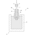
- FIG. 1 is an explanatory diagram showing an example of a continuous casting apparatus used for producing a Cu—Zn—Si—Pb—P based alloy continuous cast wire rod according to an embodiment of the present invention.
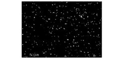
- 1 is a photograph showing the microstructure of a continuously cast wire rod in Example 11 of the present invention.
- 13 is a photograph showing the microstructure of a continuously cast wire rod in Comparative Example 9.
- FIG. 3 is a diagram in which the ⁇ phase and other phases observed in the microstructure observation photographs of FIG. 2A and FIG. 2B are binarized.
- FIG. 3 is a diagram in which the ⁇ phase and other phases observed in the microstructure observation photographs of FIG. 2A and FIG. 2B are binarized.
- FIG. 1 is an explanatory diagram showing an example of a continuous casting apparatus used for producing a Cu—Zn—Si—Pb—P based alloy continuous cast wire rod according to an embodiment of the present invention.
- 1 is a photograph showing the microstructure of a continuously cast wire rod in Example 11
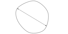
- FIG. 2 is a diagram showing a method for measuring the crystal grain size of ⁇ -phase grains.
- FIG. 2 is a diagram showing a measurement example of the area ratio of the ⁇ phase in an example.
- FIG. 2 is a diagram showing a measurement example of the area ratio of the ⁇ phase in an example.
- 1 is a photograph showing the microstructure of a continuously cast wire rod in Example 11 of the present invention after heat treatment.
- 13 is a photograph showing the microstructure of a continuously cast wire rod after heat treatment in Comparative Example 9.
- FIG. 7 is a diagram in which the ⁇ phase and other phases observed in the microstructure observation photographs of FIGS. 6A and 6B are binarized.
- FIG. 7 is a diagram in which the ⁇ phase and other phases observed in the microstructure observation photographs of FIGS.
- FIG. 13 is an explanatory diagram of oscillation depth and discoloration in an embodiment.
- FIG. 13 is a diagram showing an example of measuring the length of a discolored portion in an example.
- FIG. 13 is a diagram showing an example of measuring the length of a discolored portion in an example.
- FIG. 13 is a diagram showing an example of measuring the length of a discolored portion in an example.
- FIG. 2 is a diagram showing an example of measuring the average grain size of the ⁇ phase in an example.
- FIG. 2 is a diagram showing an example of measuring the average grain size of the ⁇ phase in an example.
- a Cu-Zn-Si-Pb-P based alloy continuous cast wire rod according to an embodiment of the present invention will be described below.
- the Cu-Zn-Si-Pb-P based alloy continuous cast wire rod according to the embodiment of the present invention is used as a material for various parts, such as drinking water and sanitary equipment equipment and fixtures, musical instruments, tableware, electric/home appliance/electronic device parts, automobile parts, machine parts, stationery, precision machine parts, medical parts, and industrial water, wastewater, and equipment and parts related to liquids and gases such as hydrogen, specific part names being water taps, mixer taps, stopcocks, valves, cocks, joints, water meters, gears, sensors, nuts, screws, etc.
- the Cu-Zn-Si-Pb-P based alloy continuous cast wire rod of this embodiment has a Cu content in the range of more than 60.0 mass% and less than 65.0 mass%, a Si content in the range of 0.40 mass% to 1.20 mass%, a Pb content in the range of 0.002 mass% to 0.250 mass%, a P content in the range of 0.040 mass% to 0.190 mass%, Bi as an optional element in the range of 0.001 mass% to 0.100 mass%, and the balance consisting of Zn and impurities.
- the total content of Fe, Mn, Co, and Cr is set to 0.450 mass% or less
- the total content of Sn and Al is set to 0.30 mass% or less.
- the average crystal grain size of the ⁇ phase is 500 ⁇ m or less, the dendrites and columnar crystals are separated, the point of maximum length of the ⁇ phase is the long axis, and the point of maximum length perpendicular to the long axis is the short axis, and the ratio L1/L2 of the long axis length L1 to the short axis length L2 is within the range of 1 to 4, and it is preferable that the shape is non-circular, elliptical, or polygonal.
- the tensile strength is within the range of 450 MPa to 600 MPa, and the elongation is within the range of 12% to 35%.
- a lathe equipped with a carbide tool of ISO classification symbol K10 is used to cut a circumference of a test material having a diameter of 14 mm under the conditions of a rake angle of 0°, a nose radius of 0.4 mm, a clearance angle of 6°, a cutting speed of 40 m/min, a cutting depth of 1.0 mm, and a feed rate of 0.11 mm/rev.
- the machinability index is 60 or more.
- the area ratio of the ⁇ phase is preferably 0.1% or less.
- the area ratio of fine ⁇ phase having a grain size of 10 ⁇ m or less is 30% to 60% in a cross section perpendicular to the casting direction.
- the area ratio of fine ⁇ phase having a grain size of 10 ⁇ m or less is 10% or more and 20% or less in a cross section perpendicular to the casting direction.
- the tensile strength is 400 MPa or more and 550 MPa or less and the elongation is 14% or more and 38% or less. Furthermore, in this embodiment, after carrying out a heat treatment in which the material is held at 475° C.
- the machinability index mentioned above is 80 or more when the material is cut under the conditions (dry condition) of a rake angle of 0°, a nose radius of 0.4 mm, a clearance angle of 6°, a cutting speed of 40 m/min, a cutting depth of 1.0 mm, and a feed rate of 0.11 mm/rev.
- the maximum possible cold drawing reduction ratio before wire breakage is 50% or more after heat treatment in which the wire is held at 475° C. for 120 minutes and then air-cooled.
- the oscillation mark depth is less than 50 ⁇ m.
- the cross-sectional area of a cross section perpendicular to the casting direction is preferably within a range of 12 mm2 to 227 mm2 .
- the Cu content is set to a range of 60.00 mass% or more and 65.00 mass% or less.
- the lower limit of the Cu content is preferably 62.15 mass% or more, and more preferably 62.40 mass% or more.
- the upper limit of the Cu content is preferably 63.05 mass% or less, and more preferably 63.00 mass% or less.
- Si has an effect on the formation of metal phases such as ⁇ , ⁇ , ⁇ , and ⁇ phases.
- Si has an effect of improving the machinability, strength, high-temperature deformability, wear resistance, and stress corrosion cracking resistance of the alloy of this embodiment.
- the inclusion of Si strengthens the ⁇ and ⁇ phases through solid solution, strengthening the alloy and affecting the ductility and toughness of the alloy.
- the inclusion of Si reduces the electrical conductivity of the ⁇ phase, but improves the electrical conductivity of the alloy through the formation of the ⁇ phase.
- Si reduces the viscosity of the molten metal, improves the flowability of the molten metal, and improves castability.
- the inclusion of Si enhances the hot deformability of the ⁇ and ⁇ phases in a temperature range exceeding 500° C., and reduces the hot deformation resistance, thereby enhancing the hot deformability of the alloy and reducing the deformation resistance.
- Si when Si is contained in an amount exceeding 0.400 mass%, the effect is remarkable.
- the gamma phase becomes excessive.
- the gamma phase is inferior in ductility and toughness to the beta phase, and reduces the ductility of the alloy, and in some cases increases the cutting resistance.
- the thrust of drill cutting becomes poor.
- the Si content is 1.20 mass% or less
- the amount of the gamma phase is reduced while the proportion of the beta phase is increased, so that excellent machinability can be maintained and the balance between strength and ductility becomes excellent.
- the conductivity of the alloy decreases by increasing the content of Si. This leads to a decrease in cooling during casting, causing casting defects such as shell breakage.
- the composition of Cu and Zn if there is too much Si, the solidification temperature range is widened and castability is deteriorated.
- the Si content is set to a range of 0.40 mass% or more and 1.20 mass% or less.
- the lower limit of the Si content is preferably 0.90 mass% or more, more preferably 0.93 mass% or more, while the upper limit of the Si content is preferably 1.00 mass% or less, more preferably 0.97 mass% or less.
- Pb By including a small amount of Pb and allowing a small amount of Pb particles to exist in the metal structure, the machinability is further improved.
- about 0.002 mass% of Pb is dissolved in the matrix, and any amount of Pb exceeding this amount is not dissolved in the matrix, but is dispersed as Pb particles with a diameter of about 0.1 to about 3 ⁇ m, thereby functioning as a so-called chip breaker and improving the machinability. Even a small amount of Pb is effective in improving the machinability.
- Pb is contained more than necessary, the cutting surface becomes rough, hot workability (for example, forgeability) deteriorates, and cold ductility decreases.
- the Pb content is set to a range of 0.002 mass% or more and 0.250 mass% or less.
- the lower limit of the Pb content is preferably 0.055 mass% or more, and more preferably 0.080 mass% or more.
- the upper limit of the P content is preferably 0.200 mass% or less, and more preferably 0.150 mass% or less.
- the machinability of the ⁇ phase i.e., the chip breakability of the ⁇ phase (chip breakability) can be improved and the cutting resistance can be reduced, resulting in excellent machinability as an alloy.
- compounds containing P with an average diameter of about 0.5 to 3 ⁇ m are formed in the ⁇ phase. These compounds reduce the three components of force, the main force, the feed force, and the thrust force in the case of peripheral cutting, and in the case of drill cutting, they particularly reduce the torque significantly.
- the three components of force during peripheral cutting, the torque during drill cutting, and the chip shape are linked, and the smaller the three components of force and torque, the more the chips are broken.
- the machinability index is improved.
- the critical cooling rate at which compounds containing P are formed increases, facilitating the formation of compounds containing P.
- P has the effect of finely refining the crystal grains of the ⁇ phase, and by finely refining the ⁇ phase, the machinability of copper alloy castings is improved.
- P when added together with Si, acts to facilitate the presence of particles containing Bi in the ⁇ phase, thereby contributing to improved machinability of the ⁇ phase.
- the P content is set to a range of 0.040 mass% or more and 0.190 mass% or less.
- the lower limit of the P content is preferably 0.055 mass% or more, and more preferably 0.070 mass% or more.
- the upper limit of the P content is preferably 0.150 mass% or less, and more preferably 0.100 mass% or less.
- Zn Zn is an element necessary for improving machinability, strength, high-temperature properties, and castability.
- Zn adheres to the inner wall of the mold, the self-lubrication of the graphite mold is inhibited, and the solidified shell tends to easily stick. Furthermore, the adhered Zn may reduce the heat dissipation of the mold, which may easily cause casting defects. Therefore, in this embodiment, Zn is the balance, and the lower limit of the Zn content is preferably 34.00 mass% or more, more preferably 34.80 mass% or more, and even more preferably 35.50 mass% or more.
- the upper limit of the Zn content is preferably 41.00 mass% or less, more preferably 36.80 mass% or less, and even more preferably 36.00 mass% or less.
- Bi is contained as an optional element, and is not an essential element. Bi is mainly positioned as a substitute for Pb. When Bi is contained in the presence of Pb, Pb and Bi often exist together, and particles in which Pb and Bi coexist do not impair the effect on machinability compared to Bi particles and Pb particles. The effect of Bi on the environment and human body is unknown at this stage, but is thought to be smaller than that of Pb, and by reducing the amount of Pb by containing Bi, the effect on the environment and human body is reduced. In addition, the action of Si allows particles containing Bi to be preferentially present in the ⁇ phase, improving the machinability of the ⁇ phase and making it possible to improve the machinability of the copper alloy casting by another means.
- Bi has the property of making copper alloy castings brittle.
- the upper limit of Bi must be determined taking into consideration the impact on the environment and human body, the decrease in ductility and toughness of copper alloy castings, and the problem of cracking during casting.
- Bi segregated at grain boundaries is likely to cause grain boundary cracking during casting. Since Bi has low strength, it leads to a decrease in strength and fatigue resistance.
- the Bi content when Bi is contained to further improve machinability, is set to be within the range of 0.001 mass% to 0.100 mass%.
- the lower limit of the Bi content is preferably 0.020 mass% or more, and more preferably 0.025 mass% or more.
- the upper limit of the Bi content is preferably 0.040 mass% or less, and more preferably 0.030 mass% or less.
- impurities: Fe, Mn, Co, Cr Fe, Mn, Co, and Cr are dissolved in the ⁇ , ⁇ , and ⁇ phases of Cu-Zn alloys to a certain concentration, but if Si is present, they are likely to combine with Si and may consume Si, which is effective for machinability. Then, Fe, Mn, Co, and Cr that combine with Si form Fe-Si compounds, Mn-Si compounds, Co-Si compounds, and Cr-Si compounds in the metal structure. These intermetallic compounds are very hard, so they reduce ductility. Furthermore, they may increase cutting resistance and shorten the life of the tool. Therefore, in this embodiment, the total content of impurities Fe, Mn, Co and Cr is set to less than 0.450 mass%.
- the total content of impurities, Fe, Mn, Co and Cr is preferably less than 0.30 mass%, and more preferably less than 0.20 mass%. Although not particularly limited, the total content of impurities Fe, Mn, Co, and Cr may be 0.001 mass% or more, 0.01 mass% or more, or 0.1 mass% or more.
- the total content of the impurities Sn and Al is set to less than 0.300 mass%.
- the total content of the impurities Sn and Al is preferably less than 0.20 mass%, and more preferably less than 0.10 mass%.
- the Sn content is preferably less than 0.300 mass%, and the Al content is preferably less than 0.200 mass%.
- the total content of Sn and Al as impurities may be 0.001 mass% or more, 0.01 mass% or more, or 0.05 mass% or more.
- impurities other than the above-mentioned elements include Ag, B, Ca, Sc, rare earth elements (excluding Y and Sc), V, Nb, Ta, Mo, W, Re, Ru, Os, Rh, Ir, Ni, Pd, Pt, Au, Cd, Hg, Al, Ga, In, Ge, Sn, As, Sb, Tl, Be, N, C, Li, H, and O. Since these impurities may deteriorate various characteristics, the total content of these impurities is preferably less than 0.20 mass%, more preferably less than 0.15 mass%, and even more preferably 0.10 mass% or less.
- the area ratio of the ⁇ phase is set to 0.1% or less.
- the area ratio of the ⁇ phase is preferably 0.08% or less.
- the area ratio of the ⁇ phase is preferably 0.01% or more.
- the ⁇ -phase plays a role as a good cushioning material, or the phase boundary between the ⁇ -phase and the ⁇ -phase plays a role as a stress concentration source for chip division, and the chips are divided more than in the case of a single-phase ⁇ -phase alloy. Therefore, if the proportion of granular fine ⁇ -phase grains is large, the strength will be high and the machinability will be improved.
- the area ratio of fine ⁇ phase having a grain size of 10 ⁇ m or less is set within the range of 30% to 60%.
- the lower limit of the area ratio of the fine ⁇ phase having a grain size of 10 ⁇ m or less is preferably 40% or more, and the upper limit of the area ratio of the fine ⁇ phase having a grain size of 10 ⁇ m or less is preferably 50% or less.
- the ⁇ phase has a maximum length defined as the major axis and a maximum length perpendicular to the major axis defined as the minor axis, and the ratio L1/L2 of the major axis length L1 to the minor axis length L2 is preferably within a range of 1 to 4, and has a non-circular, elliptical or polygonal shape.
- the ⁇ phase preferably has an average crystal grain size of 500 ⁇ m or less, and has a structure in which dendrites and columnar crystals are separated.
- the average grain size of the ⁇ phase may be 450 ⁇ m or less, or may be 400 ⁇ m or less.
- the average grain size of the ⁇ phase may be 10 ⁇ m or more, 50 ⁇ m or more, or 100 ⁇ m or more.
- the tensile strength is set to a range of 450 MPa or more and 600 MPa or less, and the elongation is set to a range of 12% or more and 35% or less.
- machinability is evaluated by the machinability index, which is a relative value with the cutting resistance of a commercially available free-cutting brass bar C3604 (Zn-59 mass% Cu-3 mass% Pb-0.2 mass% Fe-0.3 mass% Sn alloy) taken as 100.
- a high machinability index indicates high machinability, which leads to a longer tool life.
- the machinability index is preferably 90 or more when cutting is performed using a lathe equipped with a carbide tool with ISO classification symbol K10 under the conditions of a rake angle of 0°, a nose radius of 0.4 mm, a clearance angle of 6°, a cutting speed of 40 m/min, a cutting depth of 1.0 mm, and a feed rate of 0.11 mm/rev. (dry condition).
- the machinability index is preferably 60 or more.
- the machinability index may be 61 or more, or may be 62 or more, when the cutting speed is 110 m/min and the feed rate is 0.21 mm/rev.
- the area ratio of the ⁇ phase in the constituent phases of the metal structure is 0.1% or less, and the area ratio of the fine ⁇ phase having a grain size of 10 ⁇ m or less is 30% to 60%. Even if a heat treatment is performed at 450° C. for 120 minutes, the metal structure does not change significantly, and properties such as strength, elongation, and machinability are maintained. Therefore, the material has excellent heat resistance and is particularly suitable as a material for parts to be used in high-temperature environments.
- the area ratio of fine ⁇ phases having a grain size of 10 ⁇ m or less is 10% to 20% in a cross section perpendicular to the casting direction. Even when the steel is held under high temperature conditions, the area ratio of fine ⁇ phases having a grain size of 10 ⁇ m or less is ensured, making it possible to ensure certain characteristics.
- the strength is 400 to 550 MPa
- the elongation is 14 to 38%
- the machinability index is 80 or more under the conditions of cutting speed: 40 m/min and 0.11 mm/rev.
- the maximum possible cold drawing rate before breakage is 50%.
- the maximum possible cold drawing ratio until wire breakage occurs may be 52% or more, or may be 55% or more.
- the strength decreases and the elongation increases.
- the composition is limited to prevent the ⁇ phase (hard and brittle) from being formed even by heat treatment, so that it is possible to improve the elongation and cold workability without increasing the strength more than necessary.
- the oscillation mark depth is preferably less than 50 ⁇ m. The thinner the oscillation mark depth, the better the castability and the better the surface quality. In addition, when cutting the surface to remove the oscillation mark, it is possible to reduce the cutting allowance. Although not particularly limited, the oscillation mark depth may be less than 40 ⁇ m, or may be less than 30 ⁇ m.
- the cross-sectional area of the cross section perpendicular to the casting direction is preferably within a range of 12 mm 2 or more and 227 mm 2 or less.
- the cooling rate during casting does not become too fast, and the ⁇ phase can be sufficiently generated.
- the cooling rate during casting does not become too slow, and the ⁇ phase can be sufficiently refined.
- sufficient solidified shell strength can be ensured, and the size of oscillation marks due to the drawing stress applied during casting can be suppressed, enabling stable continuous casting.
- the Cu-Zn-Si-Pb-P alloy continuous cast wire rod of this embodiment is continuously cast using a continuous casting machine. Any of a vertical type continuous casting machine that draws out a continuously cast wire rod downward, a horizontal type continuous casting machine that draws out a continuously cast wire rod horizontally, and an upward draw-out type continuous casting machine that draws out a continuously cast wire rod upward can be used.
- the continuous casting apparatus 10 shown in FIG. 1 includes a casting furnace 11, a continuous casting mold 20 connected to the casting furnace 11, and a pinch roll 17 for drawing out the cast wire 1 produced from the continuous casting mold 20.
- the casting furnace 11 heats and melts the molten raw materials to produce and hold molten copper of a predetermined composition, and is equipped with a crucible 12 in which the molten raw materials and the molten copper are held, and a heating means (not shown) for heating this crucible 12.
- the pinch rolls 17 sandwich the cast wire 1 produced from the continuous casting mold 20 and pull it out in a drawing direction F. In this embodiment, the pinch rolls 17 are configured to pull the cast wire 1 intermittently.
- the continuous casting mold 20 includes a cylindrical mold 21 into which the supplied molten copper is poured, and a cooling section 28 for cooling the mold 21 .
- the continuous casting mold 20 is disposed above the molten copper in the casting furnace 11 via a refractory insulating material 15, and the cast wire 1 is pulled out upward.
- the mold 21 is generally cylindrical and has a casting hole 24 passing through it from one side to the other.
- the cooling section 28 is a water-cooled jacket disposed on the outer periphery of the mold 21, and is configured to cool the mold 21 by circulating cooling water.
- the melting raw material charged in the crucible 12 is heated and melted by the heating means to produce a molten copper metal having the above-mentioned composition.
- the molten copper is heated to a predetermined casting temperature and maintained in the crucible 12. Then, the molten copper is supplied to the continuous casting mold 20.
- the molten copper supplied to the continuous casting mold 20 is cooled and solidified in the mold 21 to become the cast wire 1.
- the cast wire 1 is intermittently pulled out by the pinch rolls 17, thereby continuously producing the cast wire 1.
- the cooling rate during casting (the cooling rate until the molten metal (1000° C.) is cooled to room temperature (25° C.)) is preferably within the range of 22° C./sec to 75° C./sec.
- the cooling rate is preferably within the range of 22° C./sec to 75° C./sec.
- the casting speed is preferably within the range of 0.6 m/min to 3.3 m/min.
- the cooling rate is not too high, and the ⁇ phase can be reliably generated.
- the solid phase ratio of the molten metal can be prevented from increasing during drawing, which can prevent the fluidity from decreasing, and the formation of poor molten metal running, deep oscillation marks, internal defects, and deep altered layers can be suppressed.
- the cooling rate is not too low, and the ⁇ phase can be reliably refined and generated.
- the supply of molten metal during drawing can be prevented from becoming insufficient, and the occurrence of deep oscillation marks and internal defects can be suppressed.
- the friction force between the mold and the solidified shell during drawing is not too high, and the breakage of the solidified shell and the formation of deep oscillation marks during drawing can be suppressed.
- the Cu content is in the range of more than 60.0 mass% and less than 65.0 mass%
- the Si content is in the range of 0.40 mass% or more and 1.20 mass% or less
- the Pb content is in the range of 0.002 mass% or more and 0.250 mass% or less
- the P content is in the range of 0.040 mass% or more and 0.190 mass% or less
- Bi is included as an optional element at 0.001 mass% or more.
- the content of the impurities is within the range of 0.100 mass% or less, with the balance being Zn and impurities, of which the total content of Fe, Mn, Co and Cr is 0.450 mass% or less, and the total content of Sn and Al is 0.30 mass% or less, and in the constituent phases of the metal structure, the area ratio of the ⁇ phase is 0.1% or less, and the area ratio of the fine ⁇ phase with a grain size of 10 ⁇ m or less is 30% to 60%, so that the material has excellent mechanical properties (strength, elongation) and machinability, has few manufacturing defects, and is of excellent quality. It can also be manufactured stably by continuous casting.
- the material when the tensile strength is 450 MPa or more and 600 MPa or less, and the elongation is 12% or more and 35% or less, the material has excellent strength and ductility. Therefore, it is particularly suitable as a material for various parts.
- the machinability index during cutting is 90 or more under the conditions of a cutting speed of 40 m/min and a feed rate of 0.11 mm/rev. (dry), sufficient machinability can be ensured even if the Pb content is limited to 0.190 mass% or less.
- the machinability index is 60 or more when cutting under conditions of a cutting speed of 110 m/min and a feed rate of 0.21 mm/rev. (dry), the cutting can be performed well even under more severe conditions.
- the heat resistance and various properties are sufficiently excellent.
- the heat resistance and mechanical properties are sufficiently excellent.
- the heat resistance and machinability are sufficiently excellent.
- the maximum possible cold drawing processing rate before breakage is 50% or more after heat treatment at 475°C for 120 minutes followed by air cooling, the heat resistance and processability are sufficiently excellent.
- the average crystal grain size of the ⁇ phase is 500 ⁇ m or less, the dendrites and columnar crystals are separated, the point of maximum length of the ⁇ phase is the major axis, and the point of maximum length perpendicular to the major axis is the minor axis, and the ratio L1/L2 of the major axis length L1 to the minor axis length L2 is within the range of 1 to 4, and the shape is non-circular, elliptical, or polygonal.
- the strength, ductility, and machinability are even more excellent.
- the oscillation mark depth is less than 50 ⁇ m, there are few defects during casting and the quality is excellent.
- the Cu-Zn-Si-Pb-P based alloy continuous cast wire rod according to the embodiment of the present invention has been described above.
- the present invention is not limited thereto and can be appropriately modified without departing from the technical concept of the invention.
- the wire rod is described as being manufactured using the top-drawing type continuous casting apparatus shown in FIG. 1 , but the present invention is not limited to this, and the wire rod may be manufactured using a horizontal-drawing type continuous casting apparatus that draws out the continuous cast wire rod in a horizontal direction.
- the continuously cast wire rod having a circular cross section and a cross-sectional area in the range of 12 mm2 to 227 mm2 is produced, but the present invention is not limited thereto, and the continuously cast wire rod may have a polygonal cross section, or may have a tubular cross section. Furthermore, the continuously cast wire rod may have an irregular cross section having a protrusion and a recess. Furthermore, there is no particular limitation on the cross-sectional area of the cross section perpendicular to the longitudinal direction.
- the raw materials for melting were prepared so as to have the compositions shown in Tables 1 and 2.
- 500 kg of the prepared raw materials for melting were charged into the crucible 12 of the casting furnace 11 shown in Fig. 1, and melted by heating with a heating means.
- a mold was prepared for producing a cast wire rod having an outer diameter of 6 mm (a cross-sectional area of a cross section perpendicular to the drawing direction of 28.26 mm 2 ) and a circular cross-section.
- a mold was prepared for producing a cast wire rod having an outer diameter of 17 mm (a cross-sectional area of a cross section perpendicular to the drawing direction of 226.87 mm 2 ).
- the casting conditions were set so as to obtain the cooling conditions shown in Tables 1 and 2, and a cast wire rod was drawn to cast 300 kg.
- the substrate was immersed in an etching solution (a mixture of hydrogen peroxide and ammonia water) at 30 to 40° C. and ultrasonically cleaned for 30 to 60 seconds, then immersed in water at room temperature and ultrasonically cleaned for 30 to 60 seconds, and then dried.
- an etching solution a mixture of hydrogen peroxide and ammonia water
- ⁇ -phase grains having an aspect ratio of 1:1 to 1:4 and a two-dimensional shape of an approximately circular, elliptical or polygonal shape were extracted.
- the grain size was determined as the longest distance between two points on the grain boundary of the same crystal, as shown in Figure 4.
- Fine ⁇ -phase grains having a grain size of 10 ⁇ m or less were extracted, and the area ratio was calculated using image analysis software Image Fiji.
- the obtained continuous cast wire rod having a diameter of 6 mm was cut to a length of 150 mm, and a tensile test was performed using a tensile testing machine AG-100kNX under conditions of a grip distance of 70 mm, a gauge length of 50 mm, and a tensile speed of 15 MPa/sec to evaluate the tensile strength and elongation.
- the evaluation was carried out by a cutting test using a lathe.
- a continuously cast wire rod material (cast material) having a diameter of 17 mm was cut to a diameter of 14 mm to prepare a test material.
- the extruded material of Comparative Example 9 was directly extruded with an actual machine to have a diameter of 25 mm, and then cut to have a diameter of 14 mm to prepare a specimen. The machinability test was carried out on this specimen.
- a K10 carbide tool (chip) without a chip breaker was attached to a lathe.
- the circumference of a 14 mm diameter test material was cut in a dry environment under the following conditions: rake angle: 0°, nose radius: 0.4 mm, clearance angle: 6°, cutting speed: 40, 110 m/min, cutting depth: 1.0 mm, feed rate: 0.11, 0.21 mm/rev.
- the cutting resistance of a commercially available free-cutting brass bar C3604 made of a Zn-59 mass% Cu-3 mass% Pb-0.2 mass% Fe-0.3 mass% Sn alloy was taken as 100, and the relative value of the cutting resistance of the sample (machinability index) was calculated and relative evaluation was performed. The higher the machinability index, the better the machinability.
- the description of "three component forces" refers to the combined force of the main force, feed force, and thrust force, and indicates the machinability index.
- the obtained continuously cast wire rod was heat treated using a muffle furnace under oxygen atmosphere at 475°C for 120 minutes and then air-cooled, and the strength, elongation, and machinability (machinability index) were measured using the procedures described above. Furthermore, the obtained continuously cast wire rod was heat treated in a muffle furnace under an oxygen atmosphere at 600° C. for 120 minutes and then air-cooled, and the area ratio of the fine ⁇ phase was measured by the above-mentioned procedure.
- the obtained cast wire was cut into 10 mm pieces along the center line parallel to the drawing direction.
- Emery polishing was performed in the order of #240, #400, #800, and #1500 at a pressure of 100 N and a speed of 100 r/min for 1000 s each.
- buff polishing was performed in the order of 9 ⁇ m, 3 ⁇ m, and 1 ⁇ m particles at a pressure of 30 N and a speed of 100 r/min for 1000 s each.
- the substrate was immersed in an etching solution (a mixture of hydrogen peroxide and ammonia water) at 30 to 40° C.
- FIG. 8 An example of the observation result is shown in Figure 8.
- a continuous dent or crack from the surface layer end to the center side of the cast wire sample was defined as an oscillation mark, and the start position of the oscillation mark at the surface layer end was set to the 0 mm position, and a line was drawn from the 0 mm position perpendicular to the drawing direction so as to intersect with the end position of the oscillation mark at the center side.
- the length of the line was defined as the oscillation mark depth.
- An oscillation mark depth of less than 50 ⁇ m was evaluated as "Good", and an oscillation mark depth of more than 50 ⁇ m was evaluated as "Not Good".
- Comparative Example 1 the Cu content was low (the Zn content was high), the ratio of the ⁇ phase in the area ratio of the ⁇ phase to the ⁇ phase was low (the ratio of the ⁇ phase was high), and the cold extraction processing rate until fracture was low, so workability could not be ensured.
- the machinability index was low, and the machinability was insufficient.
- the oscillation mark depth and discoloration were evaluated as "Not Good.”
- the Cu content was high (the Zn content was low), the area ratio of the ⁇ phase exceeded 0.1%, and the cold extraction processing rate up to fracture was low, so workability could not be ensured.
- the evaluation of the discolored portion was "Not Good.”
- Comparative Example 3 the Si content was low, and the cold extraction rate to fracture was low, so workability could not be ensured. Also, the machinability index was low, and machinability was insufficient. Furthermore, the oscillation mark depth was evaluated as "Not Good.” In Comparative Example 4, the Si content was high, the area ratio of the ⁇ phase exceeded 0.1%, and the cold extraction processing rate until fracture was low, so workability could not be ensured. In addition, the machinability index was low, and machinability was insufficient. Furthermore, the oscillation mark depth and discoloration were evaluated as "Not Good.”
- Comparative Example 5 which did not contain Pb, the machinability index was low and the machinability was insufficient. Also, the evaluation of the discolored portion was "Not Good.” In Comparative Example 6, the Pb content was high, and the strength was low. In addition, the cold extraction processing rate until fracture was low, and workability could not be ensured. Furthermore, the oscillation mark depth and discoloration were evaluated as "Not Good.”
- Comparative Example 7 the P content was low, the machinability index was low, and the machinability was insufficient. In addition, the cold extraction processing rate until fracture was low, and the processability could not be ensured. Furthermore, the evaluation of the discolored part was "Not Good.” In Comparative Example 8, the P content was high, the machinability index was low, and the machinability was insufficient. In addition, the cold extraction processing rate until fracture was low, and the processability could not be ensured. Furthermore, the oscillation mark depth and the discoloration were evaluated as "Not Good.”
- the examples of the present invention had excellent strength and elongation. They also had a high machinability index and excellent machinability. Furthermore, the cold extraction processing rate up to fracture was high, ensuring processability. Furthermore, the oscillation mark depth and discolored areas were rated "Good,” allowing for stable continuous casting. Furthermore, even after heat treatment, they had excellent strength, elongation, and machinability.
- the present invention can provide high-quality Cu-Zn-Si-Pb-P alloy continuous cast wire rod material that has excellent strength, elongation, and machinability, and has few defects.
- the present invention makes it possible to provide high-quality Cu-Zn-Si-Pb-P alloy continuous cast wire rods that are excellent in strength, elongation, and machinability, and have few defects.
Landscapes
- Chemical & Material Sciences (AREA)
- Engineering & Computer Science (AREA)
- Mechanical Engineering (AREA)
- Materials Engineering (AREA)
- Metallurgy (AREA)
- Organic Chemistry (AREA)
- Physics & Mathematics (AREA)
- Thermal Sciences (AREA)
- Crystallography & Structural Chemistry (AREA)
- Continuous Casting (AREA)
- Turning (AREA)
Abstract
60.0mass%超え65.0mass%未満のCu、0.40mass%以上1.20mass%以下の範囲内のSi、0.002mass%以上0.250mass%以下の範囲内のPb、0.040mass%以上0.190mass%以下の範囲内のPを含み、任意元素として0.001mass%以上0.100mass%以下のBiを含み、残部がZn及び不純物からなり、不純物であるFe,Mn,CoおよびCrの合計含有量が0.450mass%以下、SnおよびAlの合計含有量が0.30mass%以下であり、鋳造方向に直交する断面において、α相とβ相の面積割合がα:β=40~70:60~30、γ相の面積率が0.1%以下、粒径10μm以下の微細α相の面積率が30%以上60%以下である、Cu-Zn-Si-Pb-P系合金連続鋳造線棒材。
Description
本発明は、自動車部品、電気・電子機器部品、機械部品、文具、玩具、摺動部品、計器部品、精密機械部品、医療用部品、飲料用器具・部品、排水用器具・部品、工業用配管部品、及び飲料水、工業用水、排水、水素などの液体や気体に係る部品に用いられるCu-Zn-Si-Pb-P系合金連続鋳造線棒材に関連している。具体的な部品名称として、バルブ、継手、コック、給水栓、歯車、軸、軸受け、シャフト、スリーブ、スピンドル、センサー、ボルト、ナット、フレアナット、ペン先、インサートナット、袋ナット、ニップル、スペーサー、ねじなどが挙げられ、本発明は、これら切削が施される部品に用いられるCu-Zn-Si-Pb-P系合金連続鋳造線棒材に関連している。
本願は、2023年11月7日に、日本に出願された特願2023-190352号に基づき優先権を主張し、その内容をここに援用する。
本願は、2023年11月7日に、日本に出願された特願2023-190352号に基づき優先権を主張し、その内容をここに援用する。
従来から、飲料水、衛生設備に係る器具・部品、自動車部品、電気・家電部品、機械部品、文具、計器部品、医療用部品、および飲料水、工業用水、排水、水素などの液体や気体に関わる器具・部品、具体的な部品名称として、水栓金具、給水栓、混合栓、止水栓、バルブ、コック、継手、弁、水道メータなどの器具、部品には、優れた被削性を備えた、Cu-Zn-Pb合金(いわゆる快削黄銅棒、鍛造用黄銅、鋳物用黄銅)、あるいはCu-Sn-Zn-Pb合金(いわゆる青銅鋳物(leaded red brass))が一般的に使用されていた。
ここで、Cu-Zn-Pb合金の組成は、例えば、56~70mass%のCuと、1~4mass%のPbを含有し、残部がZnである。また、Cu-Sn-Zn-Pb合金の組成は、例えば、80~88mass%のCuと、1~8mass%のSn、1~8mass%のPbを含有し、残部がZnである。
ここで、Cu-Zn-Pb合金の組成は、例えば、56~70mass%のCuと、1~4mass%のPbを含有し、残部がZnである。また、Cu-Sn-Zn-Pb合金の組成は、例えば、80~88mass%のCuと、1~8mass%のSn、1~8mass%のPbを含有し、残部がZnである。
しかしながら、近年では、Pbの人体や環境に与える影響が懸念されるようになり、各国でPbに関する規制の動きが活発化している。例えば、米国カリフォルニア州では、2010年1月より、飲料水器具等に含まれるPb含有量を0.25mass%以下とする規制が発効されている。米国以外の国においても、その規制の動きは急速であり、Pb含有量の規制に対応した銅合金材料の開発が求められている。
また、その他の産業分野、自動車、電気・電子機器、機械などの産業分野においても、例えば、欧州のELV指令、RoHS指令では、快削性銅合金のPb含有量が例外的に4mass%まで認められているが、飲料水の分野と同様、例外の撤廃を含め、Pb含有量の規制強化が活発に議論されている。
そこで、Pb含有量を0.25mass%以下に限定しても優れた快削性を確保するために、Pbの代わりに優れた被削性性能を有するように結晶組織を制御したCu-Zn-Si合金(例えば、特許文献1参照)、Cu-Zn-Si-Pb-P系合金(例えば、特許文献2参照)等が提案されている。
そこで、Pb含有量を0.25mass%以下に限定しても優れた快削性を確保するために、Pbの代わりに優れた被削性性能を有するように結晶組織を制御したCu-Zn-Si合金(例えば、特許文献1参照)、Cu-Zn-Si-Pb-P系合金(例えば、特許文献2参照)等が提案されている。
ところで、銅合金を素材として上述の各種部品を製造する場合においては、各種断面を有する棒材や線材が加工用素材として用いられることがある。
棒材や線材を製造する場合、通常、大型の鋳塊を熱間で押出加工又は圧延加工することにより棒材とし、この棒材に対して、抽伸加工等の塑性加工を行うことによって製造されている。しかし、押出加工又は圧延加工を行って棒材を製造する場合には、大型の鋳塊を製造する鋳造工程と、鋳塊を加熱する加熱工程と、加熱した鋳塊を押し出す押出工程又は圧延工程と、多くの工程を行う必要があり、多大な製造コスト及び製造時間を要するものであった。
棒材や線材を製造する場合、通常、大型の鋳塊を熱間で押出加工又は圧延加工することにより棒材とし、この棒材に対して、抽伸加工等の塑性加工を行うことによって製造されている。しかし、押出加工又は圧延加工を行って棒材を製造する場合には、大型の鋳塊を製造する鋳造工程と、鋳塊を加熱する加熱工程と、加熱した鋳塊を押し出す押出工程又は圧延工程と、多くの工程を行う必要があり、多大な製造コスト及び製造時間を要するものであった。
そこで、金属の棒材又は線材を低コストで効率良く製造する方法として、例えば特許文献3-6に開示されているように、金属の溶湯が貯留された鋳造炉に鋳型を設置し、棒状の鋳塊を連続的に鋳造する連続鋳造法が提供されている。なお、上述の鋳型においては、通常、グラファイトのように自己潤滑性を有するモールドが用いられている。
ところで、Cu-Zn-Si-Pb-P系合金を特許文献3-6に記載されたように連続鋳造する場合には、以下のような問題があった。
(1)鋳造時に引け巣発生などの鋳造面での問題。
(2)粗大デンドライトが存在すること、および、熱処理によりγ相が必要以上に形成されることによる冷間加工性の低下。
(3)最終線径時での鋳造組織や粗大粒の残存による機械特性(伸び、強度)の低下。
(4)Snなどの偏析。
(5)粒界に偏析したPb、Biによる粒界割れ。
(6)凝固温度範囲が広いため、鋳造中のシェル破れ等の鋳造欠陥が発生し易い。
(7)Zn、Si等を含有していることから、熱伝導率低下して鋳造中の冷却が不足し易く、鋳造欠陥が発生し易い。
(8)Znの鋳付きによるモールド抜熱性低下や引抜時の拘束力上昇による鋳肌割れの増加。
(1)鋳造時に引け巣発生などの鋳造面での問題。
(2)粗大デンドライトが存在すること、および、熱処理によりγ相が必要以上に形成されることによる冷間加工性の低下。
(3)最終線径時での鋳造組織や粗大粒の残存による機械特性(伸び、強度)の低下。
(4)Snなどの偏析。
(5)粒界に偏析したPb、Biによる粒界割れ。
(6)凝固温度範囲が広いため、鋳造中のシェル破れ等の鋳造欠陥が発生し易い。
(7)Zn、Si等を含有していることから、熱伝導率低下して鋳造中の冷却が不足し易く、鋳造欠陥が発生し易い。
(8)Znの鋳付きによるモールド抜熱性低下や引抜時の拘束力上昇による鋳肌割れの増加。
以上のような各種問題が生じるおそれがあるため、欠陥の少ない高品質なCu-Zn-Si-Pb-P系合金からなる線棒材を安定して連続鋳造することは困難であった。
また、Cu-Zn-Si-Pb-P系合金においては、従来にも増して、機械特性(強度、伸び)、被削性の向上が求められている。
また、Cu-Zn-Si-Pb-P系合金においては、従来にも増して、機械特性(強度、伸び)、被削性の向上が求められている。
本発明は、以上のような事情を背景としてなされたものであって、強度、伸び、被削性に優れ、かつ、欠陥の少ない高品質なCu-Zn-Si-Pb-P系合金連続鋳造線棒材を提供することを目的としている。
上述の課題を解決するために、本発明の態様1のCu-Zn-Si-Pb-P系合金連続鋳造線棒材は、60.0mass%超え65.0mass%未満のCuと、0.40mass%以上1.20mass%以下の範囲内のSiと、0.002mass%以上0.250mass%以下の範囲内のPbと、0.040mass%以上0.190mass%以下の範囲内のPを含み、任意元素として0.001mass%以上0.100mass%以下のBiを含み、残部がZn及び不純物からなり、前記不純物のうち、Fe,Mn,CoおよびCrの合計含有量が0.450mass%以下であり、かつ、SnおよびAlの合計含有量が0.30mass%以下であり、鋳造方向に直交する断面において、α相とβ相の面積割合がα:β=40~70:60~30であり、γ相の面積率が0.1%以下であり、粒径10μm以下の微細α相の面積率が30%以上60%以下であることを特徴としている。
本発明の態様1のCu-Zn-Si-Pb-P系合金連続鋳造線棒材においては、成分組成が上述のように規定されており、鋳造方向に直交する断面において、α相とβ相の面積割合がα:β=40~70:60~30であり、γ相の面積率が0.1%以下であり、粒径10μm以下の微細α相の面積率が30%以上60%以下とされているので、機械特性(強度、伸び)、被削性に優れるとともに、製造欠陥が少なく品質に優れている。また、連続鋳造によって安定して製造することが可能である。
本発明の態様2のCu-Zn-Si-Pb-P系合金連続鋳造線棒材は、本発明の態様1のCu-Zn-Si-Pb-P系合金連続鋳造線棒材において、引張強度が450MPa以上600MPa以下、伸びが12%以上35%以下であることを特徴としている。
本発明の態様2のCu-Zn-Si-Pb-P系合金連続鋳造線棒材によれば、引張強度が450MPa以上600MPa以下、伸びが12%以上35%以下とされており、強度及び延性に優れている。よって、各種部品の素材として特に適している。
本発明の態様2のCu-Zn-Si-Pb-P系合金連続鋳造線棒材によれば、引張強度が450MPa以上600MPa以下、伸びが12%以上35%以下とされており、強度及び延性に優れている。よって、各種部品の素材として特に適している。
本発明の態様3のCu-Zn-Si-Pb-P系合金連続鋳造線棒材は、本発明の態様1または態様2のCu-Zn-Si-Pb-P系合金連続鋳造線棒材において、ISO分類記号K10の超硬工具を取り付けた旋盤を用い、すくい角:0°、ノーズ半径:0.4mm、逃げ角:6°、切削速度:40m/分、切り込み深さ:1.0mm、送り速度:0.11mm/rev.の条件下(乾式下)で、切削加工した直径14mmの試験材円周上を切削した際に、工具に取り付けられた動力計による計測値から以下の(1)式で算出される切削抵抗が、Zn-59mass%Cu-3mass%Pb-0.2mass%Fe-0.3mass%Sn合金からなる市販快削黄銅棒C3604の切削抵抗を100とした相対値である被削性指数が90以上となることを特徴としている。
(1)式:切削抵抗=((主分力)2+(送り分力)2+(背分力)2)1/2
本発明の態様3のCu-Zn-Si-Pb-P系合金連続鋳造線棒材によれば、C3604の切削抵抗を100とした相対値である被削性指数が90以上とされているので、被削性に優れている。
(1)式:切削抵抗=((主分力)2+(送り分力)2+(背分力)2)1/2
本発明の態様3のCu-Zn-Si-Pb-P系合金連続鋳造線棒材によれば、C3604の切削抵抗を100とした相対値である被削性指数が90以上とされているので、被削性に優れている。
本発明の態様4のCu-Zn-Si-Pb-P系合金連続鋳造線棒材は、本発明の態様1から態様3のいずれかひとつのCu-Zn-Si-Pb-P系合金連続鋳造線棒材において、ISO分類記号K10の超硬工具を取り付けた旋盤を用い、すくい角:0°、ノーズ半径:0.4mm、逃げ角:6°、切削速度:110m/分、切り込み深さ:1.0mm、送り速度:0.21mm/rev.の条件下(乾式下)で、切削加工した直径14mmの試験材円周上を切削した際に、工具に取り付けられた動力計による計測値から以下の(1)式で算出される切削抵抗が、Zn-59mass%Cu-3mass%Pb-0.2mass%Fe-0.3mass%Sn合金からなる市販快削黄銅棒C3604の切削抵抗を100とした相対値である被削性指数が60以上となることを特徴としている。
(1)式:切削抵抗=((主分力)2+(送り分力)2+(背分力)2)1/2
本発明の態様4のCu-Zn-Si-Pb-P系合金連続鋳造線棒材によれば、厳しい条件で切削加工した場合であっても、C3604の切削抵抗を100とした相対値である被削性指数が60以上とされているので、被削性に十分に優れている。
(1)式:切削抵抗=((主分力)2+(送り分力)2+(背分力)2)1/2
本発明の態様4のCu-Zn-Si-Pb-P系合金連続鋳造線棒材によれば、厳しい条件で切削加工した場合であっても、C3604の切削抵抗を100とした相対値である被削性指数が60以上とされているので、被削性に十分に優れている。
本発明の態様5のCu-Zn-Si-Pb-P系合金連続鋳造線棒材は、本発明の態様1から態様4のいずれかひとつのCu-Zn-Si-Pb-P系合金連続鋳造線棒材において、450℃で120分保持後に空冷する熱処理を実施後において、金属組織の構成相において、γ相の面積率が0.1%以下であり、粒径10μm以下の微細α相の面積率が30%以上60%以下であることを特徴としている。
本発明の態様5のCu-Zn-Si-Pb-P系合金連続鋳造線棒材によれば、450℃で120分保持後に空冷する熱処理を実施しても、γ相の面積率が0.1%以下に制限されるとともに、粒径10μm以下の微細α相の面積率が30%以上60%以下とされているので、耐熱性および延性に十分に優れている。
本発明の態様5のCu-Zn-Si-Pb-P系合金連続鋳造線棒材によれば、450℃で120分保持後に空冷する熱処理を実施しても、γ相の面積率が0.1%以下に制限されるとともに、粒径10μm以下の微細α相の面積率が30%以上60%以下とされているので、耐熱性および延性に十分に優れている。
本発明の態様6のCu-Zn-Si-Pb-P系合金連続鋳造線棒材は、本発明の態様1から態様5のいずれかひとつのCu-Zn-Si-Pb-P系合金連続鋳造線棒材において、475℃で120分保持後に空冷する熱処理を実施後において、引張強度が400MPa以上550MPa以下、伸びが14%以上38%以下であることを特徴としている。
本発明の態様6のCu-Zn-Si-Pb-P系合金連続鋳造線棒材によれば、475℃で120分保持後に空冷する熱処理を実施しても、γ引張強度が400MPa以上550MPa以下、伸びが14%以上38%以下とされているので、耐熱性および機械特性に十分に優れている。
本発明の態様6のCu-Zn-Si-Pb-P系合金連続鋳造線棒材によれば、475℃で120分保持後に空冷する熱処理を実施しても、γ引張強度が400MPa以上550MPa以下、伸びが14%以上38%以下とされているので、耐熱性および機械特性に十分に優れている。
本発明の態様7のCu-Zn-Si-Pb-P系合金連続鋳造線棒材は、本発明の態様1から態様6のいずれかひとつのCu-Zn-Si-Pb-P系合金連続鋳造線棒材において、475℃で120分保持後に空冷する熱処理を実施後において、ISO分類記号K10の超硬工具を取り付けた旋盤を用い、すくい角:0°、ノーズ半径:0.4mm、逃げ角:6°、切削速度:40m/分、切り込み深さ:1.0mm、送り速度:0.11mm/rev.の条件下(乾式下)で、切削加工した直径14mmの試験材円周上を切削した際に、工具に取り付けられた動力計による計測値から以下の(1)式で算出される切削抵抗が、Zn-59mass%Cu-3mass%Pb-0.2mass%Fe-0.3mass%Sn合金からなる市販快削黄銅棒C3604の切削抵抗を100とした相対値である被削性指数が80以上となることを特徴としている。
(1)式:切削抵抗=((主分力)2+(送り分力)2+(背分力)2)1/2
本発明の態様7のCu-Zn-Si-Pb-P系合金連続鋳造線棒材によれば、475℃で120分保持後に空冷する熱処理を実施しても、上述の被削性指数が80以上とされているので、耐熱性および被削性に十分に優れている。
(1)式:切削抵抗=((主分力)2+(送り分力)2+(背分力)2)1/2
本発明の態様7のCu-Zn-Si-Pb-P系合金連続鋳造線棒材によれば、475℃で120分保持後に空冷する熱処理を実施しても、上述の被削性指数が80以上とされているので、耐熱性および被削性に十分に優れている。
本発明の態様8のCu-Zn-Si-Pb-P系合金連続鋳造線棒材は、本発明の態様1から態様7のいずれかひとつのCu-Zn-Si-Pb-P系合金連続鋳造線棒材において、475℃で120分保持後に空冷する熱処理を実施後において、断線する迄の最大可能冷間抽伸加工率が50%以上であることを特徴としている。
本発明の態様8のCu-Zn-Si-Pb-P系合金連続鋳造線棒材によれば、475℃で120分保持後に空冷する熱処理を実施しても、断線する迄の最大可能冷間抽伸加工率が50%以上とされているので、耐熱性および加工性に十分に優れている。
本発明の態様8のCu-Zn-Si-Pb-P系合金連続鋳造線棒材によれば、475℃で120分保持後に空冷する熱処理を実施しても、断線する迄の最大可能冷間抽伸加工率が50%以上とされているので、耐熱性および加工性に十分に優れている。
本発明の態様9のCu-Zn-Si-Pb-P系合金連続鋳造線棒材は、本発明の態様1から態様8のいずれかひとつのCu-Zn-Si-Pb-P系合金連続鋳造線棒材において、600℃で120分保持後に空冷する熱処理を実施後において、鋳造方向に直交する断面において、粒径10μm以下の微細α相の面積率が10%以上20%以下であることを特徴としている。
本発明の態様9のCu-Zn-Si-Pb-P系合金連続鋳造線棒材によれば、600℃で120分保持後に空冷する熱処理を実施しても、鋳造方向に直交する断面において、粒径10μm以下の微細α相の面積率が10%以上20%以下とされているので、耐熱性および強度にさらに優れている。
本発明の態様9のCu-Zn-Si-Pb-P系合金連続鋳造線棒材によれば、600℃で120分保持後に空冷する熱処理を実施しても、鋳造方向に直交する断面において、粒径10μm以下の微細α相の面積率が10%以上20%以下とされているので、耐熱性および強度にさらに優れている。
本発明の態様10のCu-Zn-Si-Pb-P系合金連続鋳造線棒材は、本発明の態様1から態様9のいずれかひとつのCu-Zn-Si-Pb-P系合金連続鋳造線棒材において、鋳造方向に直交する断面において、β相の平均結晶粒径が500μm以下で、デンドライトおよび柱状晶が分断された結晶組織を有し、α相の最大長さの箇所を長軸、長軸に直交する最大長さの箇所を短軸として、長軸長さL1と短軸長さL2との比L1/L2が1以上4以下の範囲内であり、非円形状、楕円形状または多角形状をなすことを特徴としている。
本発明の態様10のCu-Zn-Si-Pb-P系合金連続鋳造線棒材によれば、上述のようにβ相およびα相が規定されているので、強度、延性、被削性にさらに優れている。
本発明の態様10のCu-Zn-Si-Pb-P系合金連続鋳造線棒材によれば、上述のようにβ相およびα相が規定されているので、強度、延性、被削性にさらに優れている。
本発明の態様11のCu-Zn-Si-Pb-P系合金連続鋳造線棒材は、本発明の態様1から態様10のいずれかひとつのCu-Zn-Si-Pb-P系合金連続鋳造線棒材において、オシレーションマーク深さが50μm未満であることを特徴としている。
本発明の態様11のCu-Zn-Si-Pb-P系合金連続鋳造線棒材によれば、オシレーションマーク深さが50μm未満とされているので、鋳造時における欠陥が少なく品質に優れている。
本発明の態様11のCu-Zn-Si-Pb-P系合金連続鋳造線棒材によれば、オシレーションマーク深さが50μm未満とされているので、鋳造時における欠陥が少なく品質に優れている。
本発明の態様12のCu-Zn-Si-Pb-P系合金連続鋳造線棒材は、本発明の態様1から態様11のいずれかひとつのCu-Zn-Si-Pb-P系合金連続鋳造線棒材において、鋳造方向に直交する断面の断面積が12mm2以上227mm2以下の範囲内であることを特徴としている。
本発明の態様12のCu-Zn-Si-Pb-P系合金連続鋳造線棒材によれば、鋳造方向に直交する断面の断面積が12mm2以上227mm2以下の範囲内とされているので、各種部品を効率的に製造することができる。
本発明の態様12のCu-Zn-Si-Pb-P系合金連続鋳造線棒材によれば、鋳造方向に直交する断面の断面積が12mm2以上227mm2以下の範囲内とされているので、各種部品を効率的に製造することができる。
本発明によれば、強度、伸び、被削性に優れ、かつ、欠陥の少ない高品質なCu-Zn-Si-Pb-P系合金連続鋳造線棒材を提供することができる。
以下に、本発明の実施形態に係るCu-Zn-Si-Pb-P系合金連続鋳造線棒材について説明する。
本発明の実施形態に係るCu-Zn-Si-Pb-P系合金連続鋳造線棒材は、飲料水、衛生設備に関わる器具・備品、楽器、食器、電気・家電・電子機器部品、自動車部品、機械部品、文具、精密機械部品、医療用部品、および工業用水、排水、水素などの液体や気体に関わる器具・部品、具体的な部品名称として、給水栓、混合栓、止水栓、バルブ、コック、継手、水道メータ、歯車、センサー、ナット、ねじ等の各種部品の素材として用いられるものである。
本発明の実施形態に係るCu-Zn-Si-Pb-P系合金連続鋳造線棒材は、飲料水、衛生設備に関わる器具・備品、楽器、食器、電気・家電・電子機器部品、自動車部品、機械部品、文具、精密機械部品、医療用部品、および工業用水、排水、水素などの液体や気体に関わる器具・部品、具体的な部品名称として、給水栓、混合栓、止水栓、バルブ、コック、継手、水道メータ、歯車、センサー、ナット、ねじ等の各種部品の素材として用いられるものである。
本実施形態であるCu-Zn-Si-Pb-P系合金連続鋳造線棒材は、Cuの含有量が60.0mass%超え65.0mass%未満の範囲内、Siの含有量が0.40mass%以上1.20mass%以下の範囲内の範囲内、Pbの含有量が0.002mass%以上0.250mass%以下の範囲内、Pの含有量が0.040mass%以上0.190mass%以下の範囲内、任意元素としてBiを0.001mass%以上0.100mass%以下の範囲内、残部がZn及び不純物からなる組成とされている。
また、不純物のうち、Fe,Mn,CoおよびCrの合計含有量が0.450mass%以下であり、かつ、SnおよびAlの合計含有量が0.30mass%以下とされている。
そして、鋳造方向に直交する断面において、α相とβ相の面積割合がα:β=40~70:60~30であり、γ相の面積率が0.1%以下であり、粒径10μm以下の微細α相の面積率が30%以上60%以下とされている。
また、不純物のうち、Fe,Mn,CoおよびCrの合計含有量が0.450mass%以下であり、かつ、SnおよびAlの合計含有量が0.30mass%以下とされている。
そして、鋳造方向に直交する断面において、α相とβ相の面積割合がα:β=40~70:60~30であり、γ相の面積率が0.1%以下であり、粒径10μm以下の微細α相の面積率が30%以上60%以下とされている。
また、本実施形態においては、鋳造方向に直交する断面において、β相の平均結晶粒径が500μm以下で、デンドライトおよび柱状晶が分断された結晶組織を有し、α相の最大長さの箇所を長軸、長軸に直交する最大長さの箇所を短軸として、長軸長さL1と短軸長さL2との比L1/L2が1以上4以下の範囲内であり、非円形状、楕円形状または多角形状をなすことが好ましい。
また、本実施形態においては、引張強度が450MPa以上600MPa以下の範囲内、伸びが12%以上35%以下の範囲内であることが好ましい。
さらに、本実施形態においては、ISO分類記号K10の超硬工具を取り付けた旋盤を用い、すくい角:0°、ノーズ半径:0.4mm、逃げ角:6°、切削速度:40m/分、切り込み深さ:1.0mm、送り速度:0.11mm/rev.の条件下(乾式下)で、切削加工した直径14mmの試験材円周上を切削した際に、工具に取り付けられた動力計による計測値から以下の(1)式で算出される切削抵抗が、Zn-59mass%Cu-3mass%Pb-0.2mass%Fe-0.3mass%Sn合金からなる市販快削黄銅棒C3604の切削抵抗を100とした相対値である被削性指数が90以上とされていることが好ましい。
(1)式:切削抵抗=((主分力)2+(送り分力)2+(背分力)2)1/2
(1)式:切削抵抗=((主分力)2+(送り分力)2+(背分力)2)1/2
また、本実施形態においては、切削速度:110m/分、送り速度:0.11mm/rev.の厳しい条件で切削した場合に、上述の被削性指数が60以上とされていることが好ましい。
さらに、本実施形態においては、450℃で120分保持後に空冷する熱処理を実施後において、γ相の面積率が0.1%以下であることが好ましい。
また、450℃で120分保持後に空冷する熱処理を実施後において、鋳造方向に直交する断面において、粒径10μm以下の微細α相の面積率が30%以上60%以下であることが好ましい。
さらに、本実施形態においては、600℃で120分保持後に空冷する熱処理を実施後において、鋳造方向に直交する断面において、粒径10μm以下の微細α相の面積率が10%以上20%以下であることが好ましい。
また、450℃で120分保持後に空冷する熱処理を実施後において、鋳造方向に直交する断面において、粒径10μm以下の微細α相の面積率が30%以上60%以下であることが好ましい。
さらに、本実施形態においては、600℃で120分保持後に空冷する熱処理を実施後において、鋳造方向に直交する断面において、粒径10μm以下の微細α相の面積率が10%以上20%以下であることが好ましい。
また、本実施形態においては、475℃で120分保持後に空冷する熱処理を実施後において、引張強度が400MPa以上550MPa以下、伸びが14%以上38%以下であることが好ましい。
さらに、本実施形態においては、475℃で120分保持後に空冷する熱処理を実施後において、すくい角:0°、ノーズ半径:0.4mm、逃げ角:6°、切削速度:40m/分、切り込み深さ:1.0mm、送り速度:0.11mm/rev.の条件下(乾式下)で切削した際の、上述の被削性指数が80以上とされていることが好ましい。
また、本実施形態においては、475℃で120分保持後に空冷する熱処理を実施後において、断線する迄の最大可能冷間抽伸加工率が50%以上であることが好ましい。
さらに、本実施形態においては、475℃で120分保持後に空冷する熱処理を実施後において、すくい角:0°、ノーズ半径:0.4mm、逃げ角:6°、切削速度:40m/分、切り込み深さ:1.0mm、送り速度:0.11mm/rev.の条件下(乾式下)で切削した際の、上述の被削性指数が80以上とされていることが好ましい。
また、本実施形態においては、475℃で120分保持後に空冷する熱処理を実施後において、断線する迄の最大可能冷間抽伸加工率が50%以上であることが好ましい。
さらに、本実施形態においては、オシレーションマーク深さが50μm未満であることが好ましい。
また、本実施形態においては、鋳造方向に直交する断面の断面積が12mm2以上227mm2以下の範囲内であることが好ましい。
また、本実施形態においては、鋳造方向に直交する断面の断面積が12mm2以上227mm2以下の範囲内であることが好ましい。
以下に、組成、金属組織、連続鋳造線棒材の機械特性および被削性、熱処理後の金属組織、熱処理後の機械特性および被削性を、上述のように規定した理由について説明する。
(Cu)
Cu含有量が、60.00mass%未満の場合、Si,Zn,P,Pbの含有量や、製造プロセスにもよるが、β相の占める割合が80%を超え、延性が低下するおそれがある。また、Cu含有量を大きくすることで、耐脱亜鉛腐食性、耐応力腐食割れ性及び冷間加工性を向上させることができる。さらに、Cu含有量が少ないと、合金の熱伝導性が低下することで冷却性低下を招き、鋳造欠陥が発生するおそれがある。
一方、Cu含有量が65.00mass%より多いと、Si,Zn,P,Pbの含有量や製造プロセスにもよるが、β相の占める割合が少なくなり、かつ、γ相の占める割合が多くなる。ただし、Cuの過量添加は熱間変形能や強度を低下させることになる。
そこで、本実施形態では、Cuの含有量を60.00mass%以上65.00mass%以下の範囲内に設定している。
なお、Cuの含有量の下限は62.15mass%以上とすることが好ましく、62.40mass%以上とすることがさらに好ましい。一方、Cuの含有量の上限を63.05mass%以下とすることが好ましく、63.00mass%以下とすることがさらに好ましい。
Cu含有量が、60.00mass%未満の場合、Si,Zn,P,Pbの含有量や、製造プロセスにもよるが、β相の占める割合が80%を超え、延性が低下するおそれがある。また、Cu含有量を大きくすることで、耐脱亜鉛腐食性、耐応力腐食割れ性及び冷間加工性を向上させることができる。さらに、Cu含有量が少ないと、合金の熱伝導性が低下することで冷却性低下を招き、鋳造欠陥が発生するおそれがある。
一方、Cu含有量が65.00mass%より多いと、Si,Zn,P,Pbの含有量や製造プロセスにもよるが、β相の占める割合が少なくなり、かつ、γ相の占める割合が多くなる。ただし、Cuの過量添加は熱間変形能や強度を低下させることになる。
そこで、本実施形態では、Cuの含有量を60.00mass%以上65.00mass%以下の範囲内に設定している。
なお、Cuの含有量の下限は62.15mass%以上とすることが好ましく、62.40mass%以上とすることがさらに好ましい。一方、Cuの含有量の上限を63.05mass%以下とすることが好ましく、63.00mass%以下とすることがさらに好ましい。
(Si)
Siは、κ相、γ相、μ相、β相などの金属相の形成に影響を与える。また、Siは、本実施形態の合金の被削性、強度、高温変形能、耐摩耗性、耐応力腐食割れ性を向上させる効果を有する。さらに、Siの含有によってα相、β相が固溶強化されるため、合金が強化され、合金の延性や靭性にも影響を与える。そしてSiの含有は、α相の導電率を低くするが、β相の形成により、合金の導電率を向上させる。さらに、Siは、溶湯の粘度を下げ、湯流れ性を向上させ、鋳造性を向上させる。合金のSi濃度が高いほど、β相に含有するSi濃度が高くなり、被削性、強度が向上する。熱間加工性に関し、Siの含有により、500℃を超える温度域でのα相、β相の熱間変形能を高め、熱間変形抵抗を低くし、その結果、合金の熱間変形能を高め、変形抵抗を低くする。特にSiを0.400mass%を超えて含有すると、その効果が顕著に発揮される。
一方、Siの含有量が多すぎると、γ相が過多になる。γ相は、β相より延性、靭性に劣り、合金の延性を低下させ、場合によっては切削抵抗を高くする。γ相が過多であると、ドリル切削のスラストが悪くなる。製造プロセスやCu濃度にもよるが、Si含有量が1.20mass%以下になると、γ相の量は少なくしつつβ相の占める割合を増やすことにより、優れた被削性を保持でき、強度と延性のバランスに優れるようになる。また、Siの含有量を増やすことにより合金の導電率が低下する。鋳造中の冷却性低下を招き、シェル破れ等の鋳造欠陥を発生させる。さらに、CuとZnの配合にもよるが、Siが多すぎると、凝固温度範囲を広くし、鋳造性を悪くする。更に、固液共存相の温度範囲が広くなることで、鋳型とSiが反応して、Si含有付着物がモールド内壁に形成される。その付着物形成により鋳型の抜熱性が低下する。
そこで、本実施形態では、Siの含有量を0.40mass%以上1.20mass%以下の範囲内に設定している。
なお、Siの含有量の下限は0.90mass%以上とすることが好ましく、0.93mass%以上とすることがさらに好ましい。一方、Siの含有量の上限は1.00mass%以下とすることが好ましく、0.97mass%以下とすることがさらに好ましい。
Siは、κ相、γ相、μ相、β相などの金属相の形成に影響を与える。また、Siは、本実施形態の合金の被削性、強度、高温変形能、耐摩耗性、耐応力腐食割れ性を向上させる効果を有する。さらに、Siの含有によってα相、β相が固溶強化されるため、合金が強化され、合金の延性や靭性にも影響を与える。そしてSiの含有は、α相の導電率を低くするが、β相の形成により、合金の導電率を向上させる。さらに、Siは、溶湯の粘度を下げ、湯流れ性を向上させ、鋳造性を向上させる。合金のSi濃度が高いほど、β相に含有するSi濃度が高くなり、被削性、強度が向上する。熱間加工性に関し、Siの含有により、500℃を超える温度域でのα相、β相の熱間変形能を高め、熱間変形抵抗を低くし、その結果、合金の熱間変形能を高め、変形抵抗を低くする。特にSiを0.400mass%を超えて含有すると、その効果が顕著に発揮される。
一方、Siの含有量が多すぎると、γ相が過多になる。γ相は、β相より延性、靭性に劣り、合金の延性を低下させ、場合によっては切削抵抗を高くする。γ相が過多であると、ドリル切削のスラストが悪くなる。製造プロセスやCu濃度にもよるが、Si含有量が1.20mass%以下になると、γ相の量は少なくしつつβ相の占める割合を増やすことにより、優れた被削性を保持でき、強度と延性のバランスに優れるようになる。また、Siの含有量を増やすことにより合金の導電率が低下する。鋳造中の冷却性低下を招き、シェル破れ等の鋳造欠陥を発生させる。さらに、CuとZnの配合にもよるが、Siが多すぎると、凝固温度範囲を広くし、鋳造性を悪くする。更に、固液共存相の温度範囲が広くなることで、鋳型とSiが反応して、Si含有付着物がモールド内壁に形成される。その付着物形成により鋳型の抜熱性が低下する。
そこで、本実施形態では、Siの含有量を0.40mass%以上1.20mass%以下の範囲内に設定している。
なお、Siの含有量の下限は0.90mass%以上とすることが好ましく、0.93mass%以上とすることがさらに好ましい。一方、Siの含有量の上限は1.00mass%以下とすることが好ましく、0.97mass%以下とすることがさらに好ましい。
(Pb)
少量のPbを含有させ、少量のPb粒子を金属組織に存在させることで、被削性がさらに向上する。なお、本実施形態の組成においては、約0.002mass%のPbがマトリックスに固溶し、それを超えた量のPbはマトリックスに固溶せず、直径が約0.1~約3μmのPb粒子として分散することによって所謂チップブレーカーとして機能し、被削性を向上させる。Pbは、微量であっても被削性に効果がある。
一方、Pbを必要以上に含有した場合には、却って切削表面が粗くなるととともに、熱間での加工性(例えば、鍛造性)が悪くなり、冷間での延性も低下する。また、粒界に偏析したPbを起点とした粒界割れを鋳造中に引き起こし易くなる。さらに、Pbは低強度であるために、強度や耐疲労性の低下を招く。
そこで、本実施形態では、Pbの含有量を0.002mass%以上0.250mass%以下の範囲内に設定している。
なお、Pbの含有量の下限は0.055mass%以上とすることが好ましく、0.080mass%以上とすることがさらに好ましい。一方、Pの含有量の上限は0.200mass%以下とすることが好ましく、0.150mass%以下とすることがさらに好ましい。
少量のPbを含有させ、少量のPb粒子を金属組織に存在させることで、被削性がさらに向上する。なお、本実施形態の組成においては、約0.002mass%のPbがマトリックスに固溶し、それを超えた量のPbはマトリックスに固溶せず、直径が約0.1~約3μmのPb粒子として分散することによって所謂チップブレーカーとして機能し、被削性を向上させる。Pbは、微量であっても被削性に効果がある。
一方、Pbを必要以上に含有した場合には、却って切削表面が粗くなるととともに、熱間での加工性(例えば、鍛造性)が悪くなり、冷間での延性も低下する。また、粒界に偏析したPbを起点とした粒界割れを鋳造中に引き起こし易くなる。さらに、Pbは低強度であるために、強度や耐疲労性の低下を招く。
そこで、本実施形態では、Pbの含有量を0.002mass%以上0.250mass%以下の範囲内に設定している。
なお、Pbの含有量の下限は0.055mass%以上とすることが好ましく、0.080mass%以上とすることがさらに好ましい。一方、Pの含有量の上限は0.200mass%以下とすることが好ましく、0.150mass%以下とすることがさらに好ましい。
(P)
Pがβ相に固溶し、その量が増えるにしたがって、β相の被削性、すなわち、β相の切屑分断性(切屑の分断性)を高め、切削抵抗を下げることができ、合金としての優れた被削性を得ることができる。さらに、Pの含有と製造プロセスによって、平均で直径0.5~3μm程度の大きさのPを含む化合物が、β相内に形成される。これらの化合物により、外周切削の場合、主分力、送り分力、背分力の3分力を低下させ、ドリル切削の場合では、特にトルクを大きく引き下げる。外周切削時の3分力と、ドリル切削時のトルクと、切屑形状とは、連動しており、3分力、トルクが小さいほど、切屑は分断される。つまり、被削性指数が向上する。ここで、Pの含有量が多くなるにしたがって、Pを含む化合物が形成される臨界の冷却速度が上がり、Pを含む化合物の形成を容易にする。さらに、Pにはα相の結晶粒を細かくする作用があり、α相を細かくすることにより、銅合金鋳物の被削性を向上させる。また、Pは、Siとの共添加で、Biを含む粒子を、α相内に存在させやすくする働きがあり、α相の被削性の向上に貢献している。
一方、Pを必要以上に含有すると、析出物が粗大化して被削性への効果が飽和するだけでなく、β相中のSi濃度が低下し、被削性が却って悪くなり、延性や靭性も低下する。また、凝固温度範囲が広くなり、鋳造性が低下するとともに、鋳塊作成時に表面あるいは内部に割れが生じやすく、加工時に断線が生じやすくなる。さらに、Pはカーボンモールドと反応して鋳造性の悪化(鋳肌の悪化など)をもたらす。
そこで、本実施形態では、Pの含有量を0.040mass%以上0.190mass%以下の範囲内に設定している。
なお、Pの含有量の下限は0.055mass%以上とすることが好ましく、0.070mass%以上とすることがさらに好ましい。一方、Pの含有量の上限は0.150mass%以下とすることが好ましく、0.100mass%以下とすることがさらに好ましい。
Pがβ相に固溶し、その量が増えるにしたがって、β相の被削性、すなわち、β相の切屑分断性(切屑の分断性)を高め、切削抵抗を下げることができ、合金としての優れた被削性を得ることができる。さらに、Pの含有と製造プロセスによって、平均で直径0.5~3μm程度の大きさのPを含む化合物が、β相内に形成される。これらの化合物により、外周切削の場合、主分力、送り分力、背分力の3分力を低下させ、ドリル切削の場合では、特にトルクを大きく引き下げる。外周切削時の3分力と、ドリル切削時のトルクと、切屑形状とは、連動しており、3分力、トルクが小さいほど、切屑は分断される。つまり、被削性指数が向上する。ここで、Pの含有量が多くなるにしたがって、Pを含む化合物が形成される臨界の冷却速度が上がり、Pを含む化合物の形成を容易にする。さらに、Pにはα相の結晶粒を細かくする作用があり、α相を細かくすることにより、銅合金鋳物の被削性を向上させる。また、Pは、Siとの共添加で、Biを含む粒子を、α相内に存在させやすくする働きがあり、α相の被削性の向上に貢献している。
一方、Pを必要以上に含有すると、析出物が粗大化して被削性への効果が飽和するだけでなく、β相中のSi濃度が低下し、被削性が却って悪くなり、延性や靭性も低下する。また、凝固温度範囲が広くなり、鋳造性が低下するとともに、鋳塊作成時に表面あるいは内部に割れが生じやすく、加工時に断線が生じやすくなる。さらに、Pはカーボンモールドと反応して鋳造性の悪化(鋳肌の悪化など)をもたらす。
そこで、本実施形態では、Pの含有量を0.040mass%以上0.190mass%以下の範囲内に設定している。
なお、Pの含有量の下限は0.055mass%以上とすることが好ましく、0.070mass%以上とすることがさらに好ましい。一方、Pの含有量の上限は0.150mass%以下とすることが好ましく、0.100mass%以下とすることがさらに好ましい。
(Zn)
Znは、被削性、強度、高温特性、鋳造性を高めるために必要な元素である。一方。Znが鋳型の内壁に付着することにより、グラファイトモールドの自己潤滑性が阻害され、凝固シェルの焼き付きが発生しやすい傾向にある。更に、付着したZnがモールドの抜熱性を低下させ、鋳造欠陥が発生しやすくなるおそれがある。
そこで、本実施形態では、Znを残部としているが、Znの含有量の下限は34.00mass%以上とすることが好ましく、34.80mass%以上とすることがさらに好ましく、35.50mass%以上とすることがより好ましい。一方、Znの含有量の上限は41.00mass%以下とすることが好ましく、36.80mass%以下とすることがさらに好ましく、36.00mass%以下とすることがより好ましい。
Znは、被削性、強度、高温特性、鋳造性を高めるために必要な元素である。一方。Znが鋳型の内壁に付着することにより、グラファイトモールドの自己潤滑性が阻害され、凝固シェルの焼き付きが発生しやすい傾向にある。更に、付着したZnがモールドの抜熱性を低下させ、鋳造欠陥が発生しやすくなるおそれがある。
そこで、本実施形態では、Znを残部としているが、Znの含有量の下限は34.00mass%以上とすることが好ましく、34.80mass%以上とすることがさらに好ましく、35.50mass%以上とすることがより好ましい。一方、Znの含有量の上限は41.00mass%以下とすることが好ましく、36.80mass%以下とすることがさらに好ましく、36.00mass%以下とすることがより好ましい。
(任意元素:Bi)
Biは、任意元素として含有されるものであり、必須の元素ではない。Biは、主として、Pbの代替の位置づけになる。Pbの存在下で、Biを含有させると、多くはPbとBiが一緒に存在し、PbとBiが共存する粒子は、Bi粒子、Pb粒子と比較し、被削性への効果が損なわれない。Biの環境や人体への影響は、現段階では不明であるが、Pbより小さいと考えられ、Biの含有によりPbの量を減らすことにより、環境や人体への影響が軽減される。また、Siの作用により、Biを含む粒子を、優先的にα相内に存在させることができ、α相の被削性を改善し、別の手段で銅合金鋳物としての被削性を向上させることが可能となる。すなわち、Biを含む粒子がα相に存在する頻度が多くなると、α相の被削性が改善され、Biを含む粒子による被削性を向上させる効果は、Pb粒子による被削性を向上させる効果を超えるようになる。
一方、Biは、銅合金鋳物を、脆くする性質がある。Biの上限は、環境や人体への影響と、銅合金鋳物の延性や靱性の低下、鋳物製作時の割れの問題を考慮に入れる必要がある。また、粒界に偏析したBiを起点とした粒界割れを鋳造中に引き起こし易くなる。Biは低強度であるために、強度や耐疲労性の低下を招く。
そこで、本実施形態では、さらなる被削性の向上を図るためにBiを含有する場合には、Biの含有量を0.001mass%以上0.100mass%以下の範囲内に設定している。もちろん、Biは任意元素であることから、Biを0.001mass%未満含有する場合でも本発明の範囲内となる。
なお、Biの含有量の下限は0.020mass%以上とすることが好ましく、0.025mass%以上とすることがさらに好ましい。一方、Biの含有量の上限は0.040mass%以下とすることが好ましく、0.030mass%以下とすることがさらに好ましい。
Biは、任意元素として含有されるものであり、必須の元素ではない。Biは、主として、Pbの代替の位置づけになる。Pbの存在下で、Biを含有させると、多くはPbとBiが一緒に存在し、PbとBiが共存する粒子は、Bi粒子、Pb粒子と比較し、被削性への効果が損なわれない。Biの環境や人体への影響は、現段階では不明であるが、Pbより小さいと考えられ、Biの含有によりPbの量を減らすことにより、環境や人体への影響が軽減される。また、Siの作用により、Biを含む粒子を、優先的にα相内に存在させることができ、α相の被削性を改善し、別の手段で銅合金鋳物としての被削性を向上させることが可能となる。すなわち、Biを含む粒子がα相に存在する頻度が多くなると、α相の被削性が改善され、Biを含む粒子による被削性を向上させる効果は、Pb粒子による被削性を向上させる効果を超えるようになる。
一方、Biは、銅合金鋳物を、脆くする性質がある。Biの上限は、環境や人体への影響と、銅合金鋳物の延性や靱性の低下、鋳物製作時の割れの問題を考慮に入れる必要がある。また、粒界に偏析したBiを起点とした粒界割れを鋳造中に引き起こし易くなる。Biは低強度であるために、強度や耐疲労性の低下を招く。
そこで、本実施形態では、さらなる被削性の向上を図るためにBiを含有する場合には、Biの含有量を0.001mass%以上0.100mass%以下の範囲内に設定している。もちろん、Biは任意元素であることから、Biを0.001mass%未満含有する場合でも本発明の範囲内となる。
なお、Biの含有量の下限は0.020mass%以上とすることが好ましく、0.025mass%以上とすることがさらに好ましい。一方、Biの含有量の上限は0.040mass%以下とすることが好ましく、0.030mass%以下とすることがさらに好ましい。
(不純物:Fe,Mn,Co,Cr)
Fe,Mn,Co及びCrは、Cu-Zn合金のα相、β相、γ相にある濃度まで固溶するが、そのときSiが存在すると、Siと化合しやすく、場合によってはSiと結合し、被削性に有効なSiを消費させるおそれがある。そして、Siと化合したFe,Mn,Co及びCrは、金属組織中にFe-Si化合物,Mn-Si化合物,Co-Si化合物,Cr-Si化合物を形成する。これらの金属間化合物は非常に硬いので、延性を低下させる。更に切削抵抗を上昇させ工具の寿命を短くするおそれがある。
そこで、本実施形態においては、不純物であるFe,Mn,CoおよびCrの合計含有量を0.450mass%未満としている。
なお、不純物であるFe,Mn,CoおよびCrの合計含有量は、0.30mass%未満とすることが好ましく、0.20mass%未満とすることがさらに好ましい。
特に限定されないが、不純物であるFe,Mn,CoおよびCrの合計含有量は、0.001mass%以上であってもよく、0.01mass%以上であってもよく、0.1mass%以上であってもよい。
Fe,Mn,Co及びCrは、Cu-Zn合金のα相、β相、γ相にある濃度まで固溶するが、そのときSiが存在すると、Siと化合しやすく、場合によってはSiと結合し、被削性に有効なSiを消費させるおそれがある。そして、Siと化合したFe,Mn,Co及びCrは、金属組織中にFe-Si化合物,Mn-Si化合物,Co-Si化合物,Cr-Si化合物を形成する。これらの金属間化合物は非常に硬いので、延性を低下させる。更に切削抵抗を上昇させ工具の寿命を短くするおそれがある。
そこで、本実施形態においては、不純物であるFe,Mn,CoおよびCrの合計含有量を0.450mass%未満としている。
なお、不純物であるFe,Mn,CoおよびCrの合計含有量は、0.30mass%未満とすることが好ましく、0.20mass%未満とすることがさらに好ましい。
特に限定されないが、不純物であるFe,Mn,CoおよびCrの合計含有量は、0.001mass%以上であってもよく、0.01mass%以上であってもよく、0.1mass%以上であってもよい。
(不純物:Sn,Al)
快削性黄銅や、めっきが施された廃製品などから混入するSn,Alは、本実施形態の合金においてγ相の形成を促進させ、一見被削性に有用であるように思われる。しかしながら、SnとAlは、Cu,Zn,Siで形成されるγ相本来の性質も変化させる。また、Sn,Alは、α相より、β相に多く配分され、β相の性質を変化させる。その結果、合金の延性や靭性の低下、被削性の低下を引き起こすおそれがある。
Snの含有量が多すぎると、Snの偏析が著しくなって、熱間での延性が乏しくなり、また、冷間での加工性の低下および延性の低下を招来し、さらにはSn添加量増大に伴う凝固温度範囲が広がることになり、その結果、鋳造性の低下(割れ、ひけ巣およびざく巣の発生)、熱間加工性および冷間加工性を低下させることになる。また、Alの含有量が多すぎると、伸びが低下する。
そこで、本実施形態においては、不純物であるSnおよびAlの合計含有量を0.300mass%未満としている。
なお、不純物であるSnおよびAlの合計含有量は、0.20mass%未満とすることが好ましく、0.10mass%未満とすることがさらに好ましい。
また、Snの含有量は0.300mass%未満とすることが好ましく、Alの含有量は0.200mass%未満とすることが好ましい。
特に限定されないが、不純物であるSnおよびAlの合計含有量は、0.001mass%以上であってもよく、0.01mass%以上であってもよく、0.05mass%以上であってもよい。
快削性黄銅や、めっきが施された廃製品などから混入するSn,Alは、本実施形態の合金においてγ相の形成を促進させ、一見被削性に有用であるように思われる。しかしながら、SnとAlは、Cu,Zn,Siで形成されるγ相本来の性質も変化させる。また、Sn,Alは、α相より、β相に多く配分され、β相の性質を変化させる。その結果、合金の延性や靭性の低下、被削性の低下を引き起こすおそれがある。
Snの含有量が多すぎると、Snの偏析が著しくなって、熱間での延性が乏しくなり、また、冷間での加工性の低下および延性の低下を招来し、さらにはSn添加量増大に伴う凝固温度範囲が広がることになり、その結果、鋳造性の低下(割れ、ひけ巣およびざく巣の発生)、熱間加工性および冷間加工性を低下させることになる。また、Alの含有量が多すぎると、伸びが低下する。
そこで、本実施形態においては、不純物であるSnおよびAlの合計含有量を0.300mass%未満としている。
なお、不純物であるSnおよびAlの合計含有量は、0.20mass%未満とすることが好ましく、0.10mass%未満とすることがさらに好ましい。
また、Snの含有量は0.300mass%未満とすることが好ましく、Alの含有量は0.200mass%未満とすることが好ましい。
特に限定されないが、不純物であるSnおよびAlの合計含有量は、0.001mass%以上であってもよく、0.01mass%以上であってもよく、0.05mass%以上であってもよい。
(不純物:その他)
上述した元素以外のその他の不純物としては、Ag,B,Ca,Sc,希土類元素(Y、Scを除く),V,Nb,Ta,Mo,W,Re,Ru,Os,Rh,Ir,Ni,Pd,Pt,Au,Cd,Hg,Al,Ga,In,Ge,Sn,As,Sb,Tl,Be,N,C,Li,H,O等が挙げられる。これらの不純物は、各種特性を低下させるおそれがあることから、これらの不純物の合計含有量は0.20mass%未満が好ましく、0.15mass%未満がより好ましく、0.10mass%以下がさらに好ましい。
上述した元素以外のその他の不純物としては、Ag,B,Ca,Sc,希土類元素(Y、Scを除く),V,Nb,Ta,Mo,W,Re,Ru,Os,Rh,Ir,Ni,Pd,Pt,Au,Cd,Hg,Al,Ga,In,Ge,Sn,As,Sb,Tl,Be,N,C,Li,H,O等が挙げられる。これらの不純物は、各種特性を低下させるおそれがあることから、これらの不純物の合計含有量は0.20mass%未満が好ましく、0.15mass%未満がより好ましく、0.10mass%以下がさらに好ましい。
(α相とβ相の比率)
α相は軟質であるため、延性や靭性が高いが被削性は低い。α相が約50%の面積率で含んでも、軟質のα相自体がクッション材の役割を果たし、切削時、硬質のβ相との境界が応力集中源になって切屑を分断するので、優れたβ単相合金の被削性が維持され、場合によっては被削性が向上すると考えられる。一方、β相は、被削性は高いが、延性や靭性が低い。また、良好な伝導性を得ることができる。よって、合金の延性、靭性、および延性と強度とのバランスを考慮することが必要となる。
そこで、本実施形態では、鋳造方向に直交する断面におけるα相とβ相の面積割合をα:β=40~70:60~30とに設定している。
α相は軟質であるため、延性や靭性が高いが被削性は低い。α相が約50%の面積率で含んでも、軟質のα相自体がクッション材の役割を果たし、切削時、硬質のβ相との境界が応力集中源になって切屑を分断するので、優れたβ単相合金の被削性が維持され、場合によっては被削性が向上すると考えられる。一方、β相は、被削性は高いが、延性や靭性が低い。また、良好な伝導性を得ることができる。よって、合金の延性、靭性、および延性と強度とのバランスを考慮することが必要となる。
そこで、本実施形態では、鋳造方向に直交する断面におけるα相とβ相の面積割合をα:β=40~70:60~30とに設定している。
(γ相の面積率)
γ相は硬く脆いことから、少量のγ相が含有する場合には、被削性への改善効果は大きいが、γ相の量を増やしても被削性の改善効果は減少していく。また、γ相のデメリットとして、γ相を起点に脱亜鉛を起こす。脱亜鉛を起点とした水道管用途等のホール発生の理由になるため、γ相の割合は小さい方が好ましい。よって、延性と強度とのバランスを優れたものにするためには、γ相を大幅に制限しなければならない。
そこで、本実施形態では、γ相の面積率を0.1%以下に設定している。
なお、γ相の面積率は0.08%以下であることが好ましい。また、γ相が存在しないと、被削性および強度に劣るため、相の面積率は0.01%以上であることが好ましい。
γ相は硬く脆いことから、少量のγ相が含有する場合には、被削性への改善効果は大きいが、γ相の量を増やしても被削性の改善効果は減少していく。また、γ相のデメリットとして、γ相を起点に脱亜鉛を起こす。脱亜鉛を起点とした水道管用途等のホール発生の理由になるため、γ相の割合は小さい方が好ましい。よって、延性と強度とのバランスを優れたものにするためには、γ相を大幅に制限しなければならない。
そこで、本実施形態では、γ相の面積率を0.1%以下に設定している。
なお、γ相の面積率は0.08%以下であることが好ましい。また、γ相が存在しないと、被削性および強度に劣るため、相の面積率は0.01%以上であることが好ましい。
(微細α相の面積率)
α相結晶粒の結晶粒径が細かいほど被削性、機械的性質が良くなる。α相結晶粒が、粒状で細かいとα相の分布が均一になり、β相も分断される。このため、切削や強度・延性面において、α相が良いクッション材としての役割を果たし、或いは、α相とβ相の相境界が切屑分断の応力集中源としての役割を果たし、切屑は、β相単相合金よりむしろ分断される。したがって、粒状の微細なα相結晶粒の割合が大きくなると、強度が高くなり、被削性が上がる。一方、強度と延性のバランスを考慮すると、結晶粒径が10μm以下の微細α相の面積率が多過ぎても、必要以上な伸び、延性の低下を招く。
そこで、本実施形態では、粒径10μm以下の微細α相の面積率を30%以上60%以下の範囲内に設定している。
なお、粒径10μm以下の微細α相の面積率の下限は40%以上であることが好ましい。粒径10μm以下の微細α相の面積率の上限は50%以下であることが好ましい。
α相結晶粒の結晶粒径が細かいほど被削性、機械的性質が良くなる。α相結晶粒が、粒状で細かいとα相の分布が均一になり、β相も分断される。このため、切削や強度・延性面において、α相が良いクッション材としての役割を果たし、或いは、α相とβ相の相境界が切屑分断の応力集中源としての役割を果たし、切屑は、β相単相合金よりむしろ分断される。したがって、粒状の微細なα相結晶粒の割合が大きくなると、強度が高くなり、被削性が上がる。一方、強度と延性のバランスを考慮すると、結晶粒径が10μm以下の微細α相の面積率が多過ぎても、必要以上な伸び、延性の低下を招く。
そこで、本実施形態では、粒径10μm以下の微細α相の面積率を30%以上60%以下の範囲内に設定している。
なお、粒径10μm以下の微細α相の面積率の下限は40%以上であることが好ましい。粒径10μm以下の微細α相の面積率の上限は50%以下であることが好ましい。
(微細α相およびβ相の形状)
合金の被削性、機械的性質に及ぼす、α相の形状、分布、β相の分布に関し、α相結晶粒の形状が針状(結晶粒のアスペクト比が4を超える楕円形)であると、α相の分散が悪くなり、針状の、長辺の大きいα相が、切削時の妨げになる。そして、α相の周りのβ相の結晶粒が大きくなり、β相の分散度合いも悪くなる。したがって、合金の強度が低くなる。
そこで、本実施形態では、α相の最大長さの箇所を長軸、長軸に直交する最大長さの箇所を短軸として、長軸長さL1と短軸長さL2との比L1/L2が1以上4以下の範囲内であり、非円形状、楕円形状または多角形状をなすことが好ましい。また、β相は、平均結晶粒径が500μm以下で、デンドライトおよび柱状晶が分断された組織であることが好ましい。
特に限定されないが、β相の平均結晶粒径は、450μm以下であってもよく、400μm以下であってもよい。
また、特に限定されないが、β相の平均結晶粒径は10μm以上であってもよく、50μm以上であってもよく、100μm以上であってもよい。
合金の被削性、機械的性質に及ぼす、α相の形状、分布、β相の分布に関し、α相結晶粒の形状が針状(結晶粒のアスペクト比が4を超える楕円形)であると、α相の分散が悪くなり、針状の、長辺の大きいα相が、切削時の妨げになる。そして、α相の周りのβ相の結晶粒が大きくなり、β相の分散度合いも悪くなる。したがって、合金の強度が低くなる。
そこで、本実施形態では、α相の最大長さの箇所を長軸、長軸に直交する最大長さの箇所を短軸として、長軸長さL1と短軸長さL2との比L1/L2が1以上4以下の範囲内であり、非円形状、楕円形状または多角形状をなすことが好ましい。また、β相は、平均結晶粒径が500μm以下で、デンドライトおよび柱状晶が分断された組織であることが好ましい。
特に限定されないが、β相の平均結晶粒径は、450μm以下であってもよく、400μm以下であってもよい。
また、特に限定されないが、β相の平均結晶粒径は10μm以上であってもよく、50μm以上であってもよく、100μm以上であってもよい。
(強度、伸び)
自動車部品を始め本実施形態の使用対象となる部材、部品に対し、薄肉化、軽量化の強い要請がある。必要な強度としては、引張強さが重要視され、延性とのバランスも重要とされている。また、素材の強度を高くすることより、部品の軽量化を図ることができる。さらに、強度、伸びが低過ぎると冷間抽伸性が悪い。冷間抽伸性は、強度と伸びのバランスが重要であり、一般に強度と延性(冷間抽伸性)は相反する。強度が高すぎると、冷間抽伸性に重要な伸びが低下する。
そこで、本実施形態では、引張強度を450MPa以上600MPa以下の範囲内、伸びを12%以上35%以下の範囲内に設定している。
自動車部品を始め本実施形態の使用対象となる部材、部品に対し、薄肉化、軽量化の強い要請がある。必要な強度としては、引張強さが重要視され、延性とのバランスも重要とされている。また、素材の強度を高くすることより、部品の軽量化を図ることができる。さらに、強度、伸びが低過ぎると冷間抽伸性が悪い。冷間抽伸性は、強度と伸びのバランスが重要であり、一般に強度と延性(冷間抽伸性)は相反する。強度が高すぎると、冷間抽伸性に重要な伸びが低下する。
そこで、本実施形態では、引張強度を450MPa以上600MPa以下の範囲内、伸びを12%以上35%以下の範囲内に設定している。
(被削性)
本実施形態では、上述のように、市販快削黄銅棒C3604(Zn-59mass%Cu-3mass%Pb-0.2mass%Fe-0.3mass%Sn合金)の切削抵抗を100とした相対値である被削性指数によって被削性を評価している。ここで、被削性指数が高いと被削性が高く、工具の寿命の長期化につながる。
本実施形態では、ISO分類記号K10の超硬工具を取り付けた旋盤を用い、すくい角:0°、ノーズ半径:0.4mm、逃げ角:6°、切削速度:40m/分、切り込み深さ:1.0mm、送り速度:0.11mm/rev.の条件下(乾式下)で切削した際の被削性指数は90以上であることが好ましい。
特に限定されないが、すくい角:0°、ノーズ半径:0.4mm、逃げ角:6°、切削速度:40m/分、切り込み深さ:1.0mm、送り速度:0.11mm/rev.の条件下(乾式下)で切削した際の被削性指数は91以上であってもよく、92以上であってもよい。
また、さらに厳しい条件として、切削速度:110m/分、送り速度:0.21mm/rev.とした場合には、被削性指数は60以上であることが好ましい。
特に限定されないが、切削速度:110m/分、送り速度:0.21mm/rev.とした場合の被削性指数は、61以上であってもよく、62以上であってもよい。
本実施形態では、上述のように、市販快削黄銅棒C3604(Zn-59mass%Cu-3mass%Pb-0.2mass%Fe-0.3mass%Sn合金)の切削抵抗を100とした相対値である被削性指数によって被削性を評価している。ここで、被削性指数が高いと被削性が高く、工具の寿命の長期化につながる。
本実施形態では、ISO分類記号K10の超硬工具を取り付けた旋盤を用い、すくい角:0°、ノーズ半径:0.4mm、逃げ角:6°、切削速度:40m/分、切り込み深さ:1.0mm、送り速度:0.11mm/rev.の条件下(乾式下)で切削した際の被削性指数は90以上であることが好ましい。
特に限定されないが、すくい角:0°、ノーズ半径:0.4mm、逃げ角:6°、切削速度:40m/分、切り込み深さ:1.0mm、送り速度:0.11mm/rev.の条件下(乾式下)で切削した際の被削性指数は91以上であってもよく、92以上であってもよい。
また、さらに厳しい条件として、切削速度:110m/分、送り速度:0.21mm/rev.とした場合には、被削性指数は60以上であることが好ましい。
特に限定されないが、切削速度:110m/分、送り速度:0.21mm/rev.とした場合の被削性指数は、61以上であってもよく、62以上であってもよい。
(熱処理後の金属組織)
本実施形態では、450℃で120分保持後に空冷する熱処理を実施後において、金属組織の構成相において、γ相の面積率が0.1%以下であり、粒径10μm以下の微細α相の面積率が30%以上60%以下とされていることが好ましい。450℃で120分保持の熱処理を行っても、金属組織が大きく変化しないことになり、強度、伸び、被削性等の特性が維持されることになる、よって、耐熱性に優れ、高温環境下で使用される部品の素材として特に適している。
また、600℃で120分保持後に空冷する熱処理を実施後において、鋳造方向に直交する断面において、粒径10μm以下の微細α相の面積率が10%以上20%以下とされていることが好ましい。さらに高温条件で保持した場合でも、粒径10μm以下の微細α相の面積率が確保され、一定の特性を確保することが可能となる。
本実施形態では、450℃で120分保持後に空冷する熱処理を実施後において、金属組織の構成相において、γ相の面積率が0.1%以下であり、粒径10μm以下の微細α相の面積率が30%以上60%以下とされていることが好ましい。450℃で120分保持の熱処理を行っても、金属組織が大きく変化しないことになり、強度、伸び、被削性等の特性が維持されることになる、よって、耐熱性に優れ、高温環境下で使用される部品の素材として特に適している。
また、600℃で120分保持後に空冷する熱処理を実施後において、鋳造方向に直交する断面において、粒径10μm以下の微細α相の面積率が10%以上20%以下とされていることが好ましい。さらに高温条件で保持した場合でも、粒径10μm以下の微細α相の面積率が確保され、一定の特性を確保することが可能となる。
(熱処理後の強度、伸び、被削性指数)
本実施形態では、475℃で120分熱処理しても、強度は400~550MPa、伸び14~38%、切削速度:40m/分および0.11mm/rev.の条件での被削性指数80以上、断線する迄の最大可能冷間抽伸加工率50%を有することが好ましい。
特に限定されないが、475℃で120分保持後に空冷する熱処理を実施後において、断線する迄の最大可能冷間抽伸加工率は52%以上であってもよく、55%以上であってもよい。
熱処理すると、強度は低下し伸びは増加する。本実施形態においては、成分限定によってγ相(硬く脆い)が熱処理しても形成され難くしたために、強度を必要以上に高くすることなく、伸びや冷間加工性を向上させることが可能となる。
本実施形態では、475℃で120分熱処理しても、強度は400~550MPa、伸び14~38%、切削速度:40m/分および0.11mm/rev.の条件での被削性指数80以上、断線する迄の最大可能冷間抽伸加工率50%を有することが好ましい。
特に限定されないが、475℃で120分保持後に空冷する熱処理を実施後において、断線する迄の最大可能冷間抽伸加工率は52%以上であってもよく、55%以上であってもよい。
熱処理すると、強度は低下し伸びは増加する。本実施形態においては、成分限定によってγ相(硬く脆い)が熱処理しても形成され難くしたために、強度を必要以上に高くすることなく、伸びや冷間加工性を向上させることが可能となる。
(オシレーションマーク深さ)
本実施形態では、オシレーションマーク深さが50μm未満であることが好ましい。オシレーションマーク深さが薄いほど、鋳造性に優れており、表面品質に特に優れている。また、オシレーションマークを除去するために表面切削する場合には、切削代を少なくすることが可能となる。
特に限定されないが、オシレーションマーク深さは40μm未満であってもよく、30μm未満であってもよい。
本実施形態では、オシレーションマーク深さが50μm未満であることが好ましい。オシレーションマーク深さが薄いほど、鋳造性に優れており、表面品質に特に優れている。また、オシレーションマークを除去するために表面切削する場合には、切削代を少なくすることが可能となる。
特に限定されないが、オシレーションマーク深さは40μm未満であってもよく、30μm未満であってもよい。
(鋳造方向に直交する断面の断面積)
本実施形態では、鋳造方向に直交する断面の断面積が12mm2以上227mm2以下の範囲内であることが好ましい。
鋳造方向に直交する断面の断面積を12mm2以上とすることで、鋳造中の冷却速度が速くなり過ぎず、α相を十分に生成することができる。一方、鋳造方向に直交する断面の断面積を227mm2以下とすることで、鋳造中の冷却速度が遅くなり過ぎず、α相を十分に微細化させることができる。また、十分な凝固シェル強度を確保でき、鋳造中にかかる引抜応力によりオシレーションマークが大きくなることを抑制でき、安定して連続鋳造することが可能となる。
本実施形態では、鋳造方向に直交する断面の断面積が12mm2以上227mm2以下の範囲内であることが好ましい。
鋳造方向に直交する断面の断面積を12mm2以上とすることで、鋳造中の冷却速度が速くなり過ぎず、α相を十分に生成することができる。一方、鋳造方向に直交する断面の断面積を227mm2以下とすることで、鋳造中の冷却速度が遅くなり過ぎず、α相を十分に微細化させることができる。また、十分な凝固シェル強度を確保でき、鋳造中にかかる引抜応力によりオシレーションマークが大きくなることを抑制でき、安定して連続鋳造することが可能となる。
次に、本実施形態であるCu-Zn-Si-Pb-P系合金連続鋳造線棒材を製造する方法の一例について説明する。
本実施形態であるCu-Zn-Si-Pb-P系合金連続鋳造線棒材においては、連続鋳造装置を用いて連続鋳造される。連続鋳造線棒材を下方に引き出す縦型連続鋳造装置、連続鋳造線棒材を水平方向に引き出す横型連続鋳造装置、連続鋳造線棒材を上方に引き出す上方引出式の連続鋳造装置のいずれも適用することができる。
本実施形態であるCu-Zn-Si-Pb-P系合金連続鋳造線棒材においては、連続鋳造装置を用いて連続鋳造される。連続鋳造線棒材を下方に引き出す縦型連続鋳造装置、連続鋳造線棒材を水平方向に引き出す横型連続鋳造装置、連続鋳造線棒材を上方に引き出す上方引出式の連続鋳造装置のいずれも適用することができる。
ここで、縦型連続鋳造装置、横型連続鋳造装置では、設備導入に広大な敷地を要する。また、鋳造時の品種を切り替える際に、坩堝内の溶湯を捨てなければならない。これに対して、上方引出式の連続鋳造装置は、上方の空間を利用でき設備がコンパクトなので、広大な敷地や地下を作る必要が無く、品種切り替えもモールドを別の坩堝に移動させるだけで済むので多品種鋳造が可能で生産面で優位性がある。
そこで、本実施形態では、図1に示す上方引出式の連続鋳造装置10を用いて連続鋳造するものとして説明する。
図1に示す連続鋳造装置10は、鋳造炉11と、鋳造炉11に連結された連続鋳造用鋳型20と、連続鋳造用鋳型20から製出された鋳造線材1を引き抜くピンチロール17と、を備えている。
図1に示す連続鋳造装置10は、鋳造炉11と、鋳造炉11に連結された連続鋳造用鋳型20と、連続鋳造用鋳型20から製出された鋳造線材1を引き抜くピンチロール17と、を備えている。
鋳造炉11は、溶解原料を加熱溶解して所定の組成の銅溶湯を製出して保持するものであり、溶解原料及び銅溶湯が保持される坩堝12と、この坩堝12を加熱する加熱手段(図示なし)と、を備えている。
ピンチロール17は、連続鋳造用鋳型20から製出される鋳造線材1を挟み込み、引抜方向Fへ引き抜くものである。本実施形態では、鋳造線材1を間欠的に引き抜く構成とされている。
ピンチロール17は、連続鋳造用鋳型20から製出される鋳造線材1を挟み込み、引抜方向Fへ引き抜くものである。本実施形態では、鋳造線材1を間欠的に引き抜く構成とされている。
連続鋳造用鋳型20は、供給された銅溶湯が注入される筒状のモールド21と、モールド21を冷却する冷却部28と、を備えている。
ここで、本実施形態では、図1に示すように、連続鋳造用鋳型20は、鋳造炉11内の銅溶湯上に耐火断熱材15を介して配置されており、鋳造線材1を上方へ引き抜く構成としている。
ここで、本実施形態では、図1に示すように、連続鋳造用鋳型20は、鋳造炉11内の銅溶湯上に耐火断熱材15を介して配置されており、鋳造線材1を上方へ引き抜く構成としている。
モールド21は、概略筒状をなしており、一方側から他方側に向けて貫通する鋳造孔24が設けられている。
冷却部28は、モールド21の外周側に配設された水冷ジャケットとされており、冷却水を循環させることでモールド21を冷却する構成とされている。
冷却部28は、モールド21の外周側に配設された水冷ジャケットとされており、冷却水を循環させることでモールド21を冷却する構成とされている。
まず、鋳造炉11の原料投入口から坩堝12内に溶解原料を投入する。原料としては、Cu単体、Zn単体およびSn単体やCu-Zn母合金およびCu-Sn母合金等を用いることができる。また、ZnおよびSnを含む原料を銅原料とともに溶解してもよい。また、本合金のリサイクル材およびスクラップ材を用いてもよい。
次に、加熱手段によって坩堝12内に装入された溶解原料を加熱して溶解し、上述した成分組成に調製された銅溶湯を製出する。
この銅溶湯は、坩堝12内において所定の鋳造温度にまで加熱されて保持される。そして、この銅溶湯が、連続鋳造用鋳型20へと供給される。
この銅溶湯は、坩堝12内において所定の鋳造温度にまで加熱されて保持される。そして、この銅溶湯が、連続鋳造用鋳型20へと供給される。
連続鋳造用鋳型20内に供給された銅溶湯は、モールド21内で冷却されて凝固して鋳造線材1となる。この鋳造線材1がピンチロール17で間欠的に引き抜かれることによって、鋳造線材1が連続的に製造される。
ここで、鋳造時の冷却速度(溶湯(1000℃)が室温(25℃)まで冷却されるまでの冷却速度)は、22℃/sec以上75℃/sec以下の範囲内とすることが好ましい。
冷却速度を22℃/sec以上とすることで、α相の成長または合体を抑制でき、α相を微細化させることが可能となる。一方、冷却速度を75℃/sec以下とすることで、α相を確実に生成させることができる。
冷却速度を22℃/sec以上とすることで、α相の成長または合体を抑制でき、α相を微細化させることが可能となる。一方、冷却速度を75℃/sec以下とすることで、α相を確実に生成させることができる。
また、鋳造速度は、0.6m/min以上3.3m/min以下の範囲内とすることが好ましい。
鋳造速度を0.6m/min以上とすることで、冷却速度が大きくなり過ぎず、α相を確実に生成させることができる。また、引き抜き途中で溶湯の固相率が高くなって流動性が低下することを抑制でき、湯回り不良、深いオシレーションマーク、内部欠陥、深い変質層が形成されることを抑制できる。一方、鋳造速度を3.3m/min以下とすることで、冷却速度は小さくなり過ぎず、α相を確実に微細化生成させることができる。また、引抜の際の溶湯供給が不十分となることを抑制でき、深いオシレーションマークや内部欠陥の発生を抑制できる。また、引抜時の鋳型と凝固シェルの摩擦力が大きくなり過ぎず、引抜時における凝固シェルの破断や深いオシレーションマークの形成を抑制することができる。
鋳造速度を0.6m/min以上とすることで、冷却速度が大きくなり過ぎず、α相を確実に生成させることができる。また、引き抜き途中で溶湯の固相率が高くなって流動性が低下することを抑制でき、湯回り不良、深いオシレーションマーク、内部欠陥、深い変質層が形成されることを抑制できる。一方、鋳造速度を3.3m/min以下とすることで、冷却速度は小さくなり過ぎず、α相を確実に微細化生成させることができる。また、引抜の際の溶湯供給が不十分となることを抑制でき、深いオシレーションマークや内部欠陥の発生を抑制できる。また、引抜時の鋳型と凝固シェルの摩擦力が大きくなり過ぎず、引抜時における凝固シェルの破断や深いオシレーションマークの形成を抑制することができる。
以上のような構成とされた本実施形態であるCu-Zn-Si-Pb-P系合金連続鋳造線棒材によれば、Cuの含有量が60.0mass%超え65.0mass%未満の範囲内、Siの含有量が0.40mass%以上1.20mass%以下の範囲内の範囲内、Pbの含有量が0.002mass%以上0.250mass%以下の範囲内、Pの含有量が0.040mass%以上0.190mass%以下の範囲内、任意元素としてBiを0.001mass%以上0.100mass%以下の範囲内、残部がZn及び不純物からなり、不純物のうち、Fe,Mn,CoおよびCrの合計含有量が0.450mass%以下であり、かつ、SnおよびAlの合計含有量が0.30mass%以下とされ、金属組織の構成相において、γ相の面積率が0.1%以下であり、粒径10μm以下の微細α相の面積率が30%以上60%以下とされているので、機械特性(強度、伸び)、被削性に優れるとともに、製造欠陥が少なく品質に優れている。また、連続鋳造によって安定して製造することが可能である。
本実施形態において、鋳造方向に直交する断面におけるα相とβ相の面積割合がα:β=40~70:60~30である場合には、延性および靭性と強度および被削性とをバランス良く向上させることができる。
本実施形態において、引張強度が450MPa以上600MPa以下、伸びが12%以上35%以下とされている場合には、強度および延性に優れている。よって、各種部品の素材として特に適している。
本実施形態において、切削速度:40m/分、送り速度:0.11mm/rev.の条件下(乾式下)で、切削加工した際の被削性指数が90以上とされている場合には、Pbの含有量を0.190mass%以下に制限しても、十分な被削性を確保することが可能となる。
本実施形態において、切削速度:110m/分、送り速度:0.21mm/rev.の条件下(乾式下)で、切削加工した際の被削性指数が60以上とされている場合には、さらに厳しい条件であっても、良好に切削加工することができる。
本実施形態において、450℃で120分保持後に空冷する熱処理を実施後に、金属組織の構成相において、γ相の面積率が0.1%以下であり、粒径10μm以下の微細α相の面積率が30%以上60%以下である場合には、耐熱性および各種特性に十分に優れている。
本実施形態において、475℃で120分保持後に空冷する熱処理を実施後において、引張強度が400MPa以上550MPa以下、伸びが14%以上38%以下である場合には、耐熱性および機械特性に十分に優れている。
本実施形態において、475℃で120分保持後に空冷する熱処理を実施後において、切削速度:40m/分、送り速度:0.11mm/rev.の条件下(乾式下)で、切削加工した際の被削性指数が80以上とされている場合には、耐熱性および被削性に十分に優れている。
本実施形態において、475℃で120分保持後に空冷する熱処理を実施後において、断線する迄の最大可能冷間抽伸加工率が50%以上である場合には、耐熱性および加工性に十分に優れている。
本実施形態において、600℃で120分保持後に空冷する熱処理を実施後において、鋳造方向に直交する断面において、粒径10μm以下の微細α相の面積率が10%以上20%以下である場合には、耐熱性および強度にさらに優れている。
本実施形態において、鋳造方向に直交する断面において、β相の平均結晶粒径が500μm以下で、デンドライトおよび柱状晶が分断された結晶組織を有し、α相の最大長さの箇所を長軸、長軸に直交する最大長さの箇所を短軸として、長軸長さL1と短軸長さL2との比L1/L2が1以上4以下の範囲内であり、非円形状、楕円形状または多角形状をなす場合には、強度、延性、被削性にさらに優れている。
本実施形態において、オシレーションマーク深さが50μm未満である場合には、鋳造時における欠陥が少なく品質に優れている。
本実施形態において、鋳造方向に直交する断面の断面積が12mm2以上227mm2以下の範囲内である場合には、各種部品を効率的に製造することができる。
以上、本発明の実施形態であるCu-Zn-Si-Pb-P系合金連続鋳造線棒材について説明したが、本発明はこれに限定されることはなく、その発明の技術的思想を逸脱しない範囲で適宜変更可能である。
例えば、本実施形態では、図1に示す上方引出式の連続鋳造装置を用いて製造された上方引出連続鋳造線棒材として説明したが、これに限定されず、水平方向に連続鋳造線棒材を引き出す水平引出式の連続鋳造装置で製造したものであってもよい。
例えば、本実施形態では、図1に示す上方引出式の連続鋳造装置を用いて製造された上方引出連続鋳造線棒材として説明したが、これに限定されず、水平方向に連続鋳造線棒材を引き出す水平引出式の連続鋳造装置で製造したものであってもよい。
また、本実施形態では、断面円形で断面積が12mm2以上227mm2以下の範囲内の連続鋳造線棒材を製造するものとして説明したが、これに限定されることはなく、断面多角形の連続鋳造線棒材であってもよいし、断面が管状をなす連続鋳造線棒材であってもよい。また、断面が凸部及び凹部を有する異形状の連続鋳造線棒材であってもよい。また、その長手方向に直交する断面の断面積についても特に制限はない。
以下に、本発明の効果を確認すべく行った確認実験の結果について説明する。
表1,2に示す組成となるように、溶解原料を調製した。調製された溶解原料を、図1に示す鋳造炉11の坩堝内12に500kg装入して、加熱手段で加熱することにより溶解した。
鋳型として、外径6mm(引抜方向に直交する断面の断面積28.26mm2)の断面円形の鋳造線棒材を製造するものを準備した。また、被削性評価のために、外径17mm(引抜方向に直交する断面の断面積226.87mm2)の断面円形の鋳造線棒材を製造するものを準備した。
そして、表1,2に示す冷却条件となるように鋳造条件を設定し、鋳造線棒材の引き抜きを行って300kgの鋳造を行った。
表1,2に示す組成となるように、溶解原料を調製した。調製された溶解原料を、図1に示す鋳造炉11の坩堝内12に500kg装入して、加熱手段で加熱することにより溶解した。
鋳型として、外径6mm(引抜方向に直交する断面の断面積28.26mm2)の断面円形の鋳造線棒材を製造するものを準備した。また、被削性評価のために、外径17mm(引抜方向に直交する断面の断面積226.87mm2)の断面円形の鋳造線棒材を製造するものを準備した。
そして、表1,2に示す冷却条件となるように鋳造条件を設定し、鋳造線棒材の引き抜きを行って300kgの鋳造を行った。
得られた鋳造線材を、鋳造方向に直交する方向に切断して、ミクロ組織観察用試料とした。また、鋳造方向に平行に中心線に沿って切断し、オシレーションマーク深さ、変色部を評価するためのミクロ組織観察用試料を作成した。
上述の各種試料を、♯240、400、800、1500の順にエメリー研磨を圧力100N、速度100r/minで1000sずつ行った。次に、粒子9μm、3μm、1μmの順にバフ研磨を圧力30N、速度100r/minで1000sずつ行った。
その後、30~40℃のエッチング液(過酸化水素水とアンモニア水の混合液)に浸漬し、30~60sの超音波洗浄を行った。次に、常温の水に浸漬し、30~60sの超音波洗浄を行った後、乾燥させた。
上述の各種試料を、♯240、400、800、1500の順にエメリー研磨を圧力100N、速度100r/minで1000sずつ行った。次に、粒子9μm、3μm、1μmの順にバフ研磨を圧力30N、速度100r/minで1000sずつ行った。
その後、30~40℃のエッチング液(過酸化水素水とアンモニア水の混合液)に浸漬し、30~60sの超音波洗浄を行った。次に、常温の水に浸漬し、30~60sの超音波洗浄を行った後、乾燥させた。
(鋳造方向に直交する断面のミクロ組織)
鋳造線棒材の鋳造方向に直交する断面を光学顕微鏡により、倍率500倍で観察し、横219μm×縦275μmの領域の組織画像を得た。鋳造線棒材の前記断面の全体のミクロ組織観察結果の一例を図2A及び図2Bに示す。
鋳造線棒材の鋳造方向に直交する断面を光学顕微鏡により、倍率500倍で観察し、横219μm×縦275μmの領域の組織画像を得た。鋳造線棒材の前記断面の全体のミクロ組織観察結果の一例を図2A及び図2Bに示す。
(γ相の面積率)
上述のようにして得た組織画像を、画像解析ソフトimage fijiに取り込み、γ相の部分を白色、それ以外を黒色となるように、画像を二値化した。二値化した画像の一例を図3A及び図3Bに示す。二値化した画像からγ相の面積率を算出した。
上述のようにして得た組織画像を、画像解析ソフトimage fijiに取り込み、γ相の部分を白色、それ以外を黒色となるように、画像を二値化した。二値化した画像の一例を図3A及び図3Bに示す。二値化した画像からγ相の面積率を算出した。
(粒径10μm以下の微細α相の面積率)
上述のようにして得た組織画像からアスペクト比が1:1~1:4の2次元形態が略円形状、楕円形状または多角形状であるα相粒を抽出した。抽出したα相粒のそれぞれについて、図4に示すように、同一結晶の粒界上の2点を結ぶ線のうち最も距離が長くなる線の距離を結晶粒径とした。
粒径が10μm以下の微細α相粒を抽出し、画像解析ソフトimage fijiを用いて面積率を算出した。
上述のようにして得た組織画像からアスペクト比が1:1~1:4の2次元形態が略円形状、楕円形状または多角形状であるα相粒を抽出した。抽出したα相粒のそれぞれについて、図4に示すように、同一結晶の粒界上の2点を結ぶ線のうち最も距離が長くなる線の距離を結晶粒径とした。
粒径が10μm以下の微細α相粒を抽出し、画像解析ソフトimage fijiを用いて面積率を算出した。
(α相およびβ相の相比率)
上述のようにして得た組織画像を、画像解析ソフトimage fijiに取り込み、α相の部分を白色、それ以外(β相およびγ相)を黒色となるように、画像を二値化した。観察画像および値化画像の一例を図5A及び図5Bに示す。二値化した画像からα相の面積率を算出した。
例えば、α相の面積率が50であり、γ相の面積率が0.01である場合、β相の面積率は100―50―0.01=49.99である。よって、αとβの面積率は50:49.99となる。
上述のようにして得た組織画像を、画像解析ソフトimage fijiに取り込み、α相の部分を白色、それ以外(β相およびγ相)を黒色となるように、画像を二値化した。観察画像および値化画像の一例を図5A及び図5Bに示す。二値化した画像からα相の面積率を算出した。
例えば、α相の面積率が50であり、γ相の面積率が0.01である場合、β相の面積率は100―50―0.01=49.99である。よって、αとβの面積率は50:49.99となる。
(機械特性)
得られたφ(直径)6mmの連続鋳造線棒材を長さ150mmに切断し、引張試験機AG-100kNXを用いて、つかみ間距離70mm、標点間距離50mm、引張速度15MPa/secの条件で引張試験を行い、引張強度及び伸びを評価した。
得られたφ(直径)6mmの連続鋳造線棒材を長さ150mmに切断し、引張試験機AG-100kNXを用いて、つかみ間距離70mm、標点間距離50mm、引張速度15MPa/secの条件で引張試験を行い、引張強度及び伸びを評価した。
(被削性)
旋盤を用いた切削試験で評価した。φ17mmの連続鋳造線棒材(鋳造材)に対して、切削加工を施して直径を14mmとして試験材を作製した。
また、比較例9の押出材については、実機で直接押出しによってφ25mmに加工した後、φ14mmまで切削して試料を作製した。この試料にて切削性試験を実施した。
旋盤を用いた切削試験で評価した。φ17mmの連続鋳造線棒材(鋳造材)に対して、切削加工を施して直径を14mmとして試験材を作製した。
また、比較例9の押出材については、実機で直接押出しによってφ25mmに加工した後、φ14mmまで切削して試料を作製した。この試料にて切削性試験を実施した。
チップブレーカーの付いていないK10の超硬工具(チップ)を旋盤に取り付けた。この旋盤を用い、乾式下にて、すくい角:0°、ノーズ半径:0.4mm、逃げ角:6°、切削速度:40,110m/分、切り込み深さ:1.0mm、送り速度:0.11,0.21mm/rev.の条件で、直径14mmの試験材の円周上を切削した。
工具に取り付けられた3部分から成る動力計(三保電機製作所製、AST式工具動力計AST-TL1003)から発せられるシグナルが、電気的電圧シグナルに変換され、レコーダーに記録された。次にこれらのシグナルは切削抵抗(主分力、送り分力、背分力、N)に変換された。
切削試験は、チップの摩耗の影響を抑えるために、A→B→C→・・・C→B→Aの往復を2回実施し、各試料について4回測定した。切削抵抗は、以下の式によって求められる。
切削抵抗(主分力、送り分力、背分力の合力)=((主分力)2+(送り分力)2+(背分力)2)1/2
切削試験は、チップの摩耗の影響を抑えるために、A→B→C→・・・C→B→Aの往復を2回実施し、各試料について4回測定した。切削抵抗は、以下の式によって求められる。
切削抵抗(主分力、送り分力、背分力の合力)=((主分力)2+(送り分力)2+(背分力)2)1/2
なお、各サンプルで4回測定し、その平均値を採用した。Zn-59mass%Cu-3mass%Pb-0.2mass%Fe-0.3mass%Sn合金からなる市販の快削黄銅棒C3604の切削抵抗を100とし、試料の切削抵抗の相対値(被削性指数)を算出し、相対評価をした。被削性指数が、高いほど良好な被削性を有する。「3分力」の記載は、主分力、送り分力、背分力の合力を指し、被削性指数を示す。被削性指数は下記のようにして求めた。
試料の切削試験結果の指数(被削性指数)=(C3604の切削抵抗/試料の切削抵抗)×100
試料の切削試験結果の指数(被削性指数)=(C3604の切削抵抗/試料の切削抵抗)×100
(熱処理)
得られた連続鋳造線棒材に対して、マッフル炉を用いて酸素雰囲気下にて450℃で120分保持後空冷の条件で熱処理を行い、α相、β相、γ相の相比率、微細α相の面積率を、上述の手順で測定した。
なお、熱処理後のミクロ組織観察結果の一例を図6A及び図6Bに示す。また、γ相の部分を白色、それ以外を黒色となるように、画像を二値化した画像の一例を図7に示す。
得られた連続鋳造線棒材に対して、マッフル炉を用いて酸素雰囲気下にて450℃で120分保持後空冷の条件で熱処理を行い、α相、β相、γ相の相比率、微細α相の面積率を、上述の手順で測定した。
なお、熱処理後のミクロ組織観察結果の一例を図6A及び図6Bに示す。また、γ相の部分を白色、それ以外を黒色となるように、画像を二値化した画像の一例を図7に示す。
また、得られた連続鋳造線棒材に対して、マッフル炉を用いて酸素雰囲気下にて475℃で120分保持後空冷の条件で熱処理を行い、強度、伸び、被削性(切削性指数)を、上述の手順で測定した。
さらに、得られた連続鋳造線棒材に対して、マッフル炉を用いて酸素雰囲気下にて600℃で120分保持後空冷の条件で熱処理を行い、微細α相の面積率を、上述の手順で測定した。
さらに、得られた連続鋳造線棒材に対して、マッフル炉を用いて酸素雰囲気下にて600℃で120分保持後空冷の条件で熱処理を行い、微細α相の面積率を、上述の手順で測定した。
(破断までの冷間抽出加工率)
φ6mm鋳造線について、内径6.0mmダイスで抽伸(加工率0%)→内径5.8mmの皮剥ダイスで方肉50μmずつ表皮を除去する→内径5.5mmダイスで抽伸(内径5.8mmの線からの加工率10%)→内径5.2mmダイスで抽伸(内径5.8mmの線からの加工率20%)→内径4.8mmダイスで抽伸(内径5.8mmの線からの加工率32%)→内径4.45mmダイスで抽伸(内径5.8mmの線からの加工率41%)→内径4.0mmダイスで抽伸(内径5.8mmの線からの加工率52%)→内径3.8mmダイスで抽伸(内径5.8mmの線からの加工率57%)→内径3.6mmダイスで抽伸(内径5.8mmの線からの加工率61%)という順番で冷間抽伸試験を行う。
例えば、内径3.8mmダイスでの抽伸時に断線が発生した場合は、そのひとつ前のダイス(内径4.0mm)までは抽伸出来ていたため、破断迄の冷間抽伸加工率は加工率52%となる。このような方法で破断迄の冷間抽伸加工率を求めていく。
φ6mm鋳造線について、内径6.0mmダイスで抽伸(加工率0%)→内径5.8mmの皮剥ダイスで方肉50μmずつ表皮を除去する→内径5.5mmダイスで抽伸(内径5.8mmの線からの加工率10%)→内径5.2mmダイスで抽伸(内径5.8mmの線からの加工率20%)→内径4.8mmダイスで抽伸(内径5.8mmの線からの加工率32%)→内径4.45mmダイスで抽伸(内径5.8mmの線からの加工率41%)→内径4.0mmダイスで抽伸(内径5.8mmの線からの加工率52%)→内径3.8mmダイスで抽伸(内径5.8mmの線からの加工率57%)→内径3.6mmダイスで抽伸(内径5.8mmの線からの加工率61%)という順番で冷間抽伸試験を行う。
例えば、内径3.8mmダイスでの抽伸時に断線が発生した場合は、そのひとつ前のダイス(内径4.0mm)までは抽伸出来ていたため、破断迄の冷間抽伸加工率は加工率52%となる。このような方法で破断迄の冷間抽伸加工率を求めていく。
(オシレーションマーク深さ)
得られた鋳造線材を、引抜方向に平行に中心線に沿って10mmに切断。♯240、400、800、1500の順にエメリー研磨を圧力100N、速度100r/minで1000sずつ行った。次に、粒子9μm、3μm、1μmの順にバフ研磨を圧力30N、速度100r/minで1000sずつ行った。
その後、30~40℃のエッチング液(過酸化水素水とアンモニア水の混合液)に浸漬し、30~60sの超音波洗浄を行った。次に、常温の水に浸漬し、30~60sの超音波洗浄を行った後、乾燥させた。
光学顕微鏡にて、倍率100倍で組織観察を実施した。観察結果の一例を図8に示す。図8に示すように、鋳造線試料の表層端部から中心部側にかけて、連続した凹みや亀裂をオシレーションマークと定義し、表層端部にあるオシレーションマークの開始位置を0mm位置とし、その0mm位置から、中心部側にあるオシレーションマークの終了位置と交わるように引抜方向に直交するラインを引く。そのライン長さをオシレーションマーク深さと定義した。
オシレーションマーク深さが50μm未満を「Good」、50μm超えを「Not Good」と評価した。
得られた鋳造線材を、引抜方向に平行に中心線に沿って10mmに切断。♯240、400、800、1500の順にエメリー研磨を圧力100N、速度100r/minで1000sずつ行った。次に、粒子9μm、3μm、1μmの順にバフ研磨を圧力30N、速度100r/minで1000sずつ行った。
その後、30~40℃のエッチング液(過酸化水素水とアンモニア水の混合液)に浸漬し、30~60sの超音波洗浄を行った。次に、常温の水に浸漬し、30~60sの超音波洗浄を行った後、乾燥させた。
光学顕微鏡にて、倍率100倍で組織観察を実施した。観察結果の一例を図8に示す。図8に示すように、鋳造線試料の表層端部から中心部側にかけて、連続した凹みや亀裂をオシレーションマークと定義し、表層端部にあるオシレーションマークの開始位置を0mm位置とし、その0mm位置から、中心部側にあるオシレーションマークの終了位置と交わるように引抜方向に直交するラインを引く。そのライン長さをオシレーションマーク深さと定義した。
オシレーションマーク深さが50μm未満を「Good」、50μm超えを「Not Good」と評価した。
(変色部)
φ6の鋳造線を10mm長さで切断し、更に鋳造線中心部を通るように鋳造方向に対して水平方向に切断する。このように切断した鋳造線(切断面は6mm×10mmの長方形となる)の両方の長辺(10mmずつ。合計20mm長さ)に対して、変色部の合計長さを測定した。観察結果の一例を図9A、図9B及び図9Cに示す。
図9Aにおいては、変色部合計長さは2.4mm(変色部の長さL3を測定する為の画像は図9B及び図9Cの二つしか例に挙げていないが、実際は更に多くの観察画像から変色部合計長さを出している)であった。
φ6の鋳造線を10mm長さで切断し、更に鋳造線中心部を通るように鋳造方向に対して水平方向に切断する。このように切断した鋳造線(切断面は6mm×10mmの長方形となる)の両方の長辺(10mmずつ。合計20mm長さ)に対して、変色部の合計長さを測定した。観察結果の一例を図9A、図9B及び図9Cに示す。
図9Aにおいては、変色部合計長さは2.4mm(変色部の長さL3を測定する為の画像は図9B及び図9Cの二つしか例に挙げていないが、実際は更に多くの観察画像から変色部合計長さを出している)であった。
(β相の平均結晶粒径)
光学顕微鏡にて、倍率100倍で組織観察を実施した。観察結果の一例を図10A及び図10Bに示す。なお、図10Aが本発明例11、図10Bが比較例1である。なお、図10B中の破線で囲まれた部分はβ相である。
図10Bにおいて(比較例1について)はβ相が柱状晶形状となっている。さらに、同じ結晶の粒界上の2点を結ぶ線のうち最も距離が長くなる線の距離を結晶粒径とした場合、その粒径も500μm超えである。一方、本発明例11については、柱状晶を分断した粒状組織となっている。
β相の粒界が500μm以下であるものを「Good」、500μm超えであるものを「Not Good」として、表に記載する。
光学顕微鏡にて、倍率100倍で組織観察を実施した。観察結果の一例を図10A及び図10Bに示す。なお、図10Aが本発明例11、図10Bが比較例1である。なお、図10B中の破線で囲まれた部分はβ相である。
図10Bにおいて(比較例1について)はβ相が柱状晶形状となっている。さらに、同じ結晶の粒界上の2点を結ぶ線のうち最も距離が長くなる線の距離を結晶粒径とした場合、その粒径も500μm超えである。一方、本発明例11については、柱状晶を分断した粒状組織となっている。
β相の粒界が500μm以下であるものを「Good」、500μm超えであるものを「Not Good」として、表に記載する。

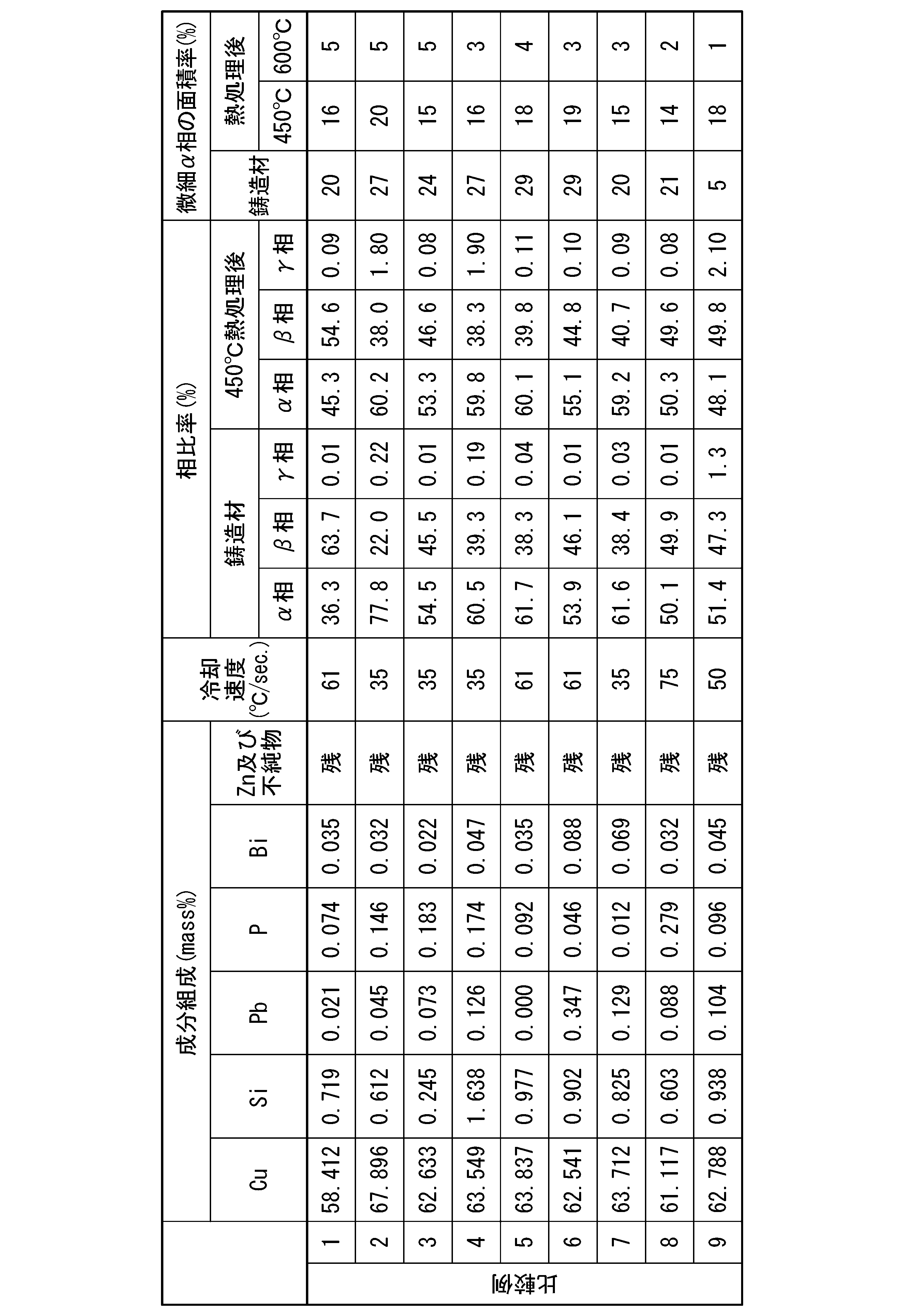

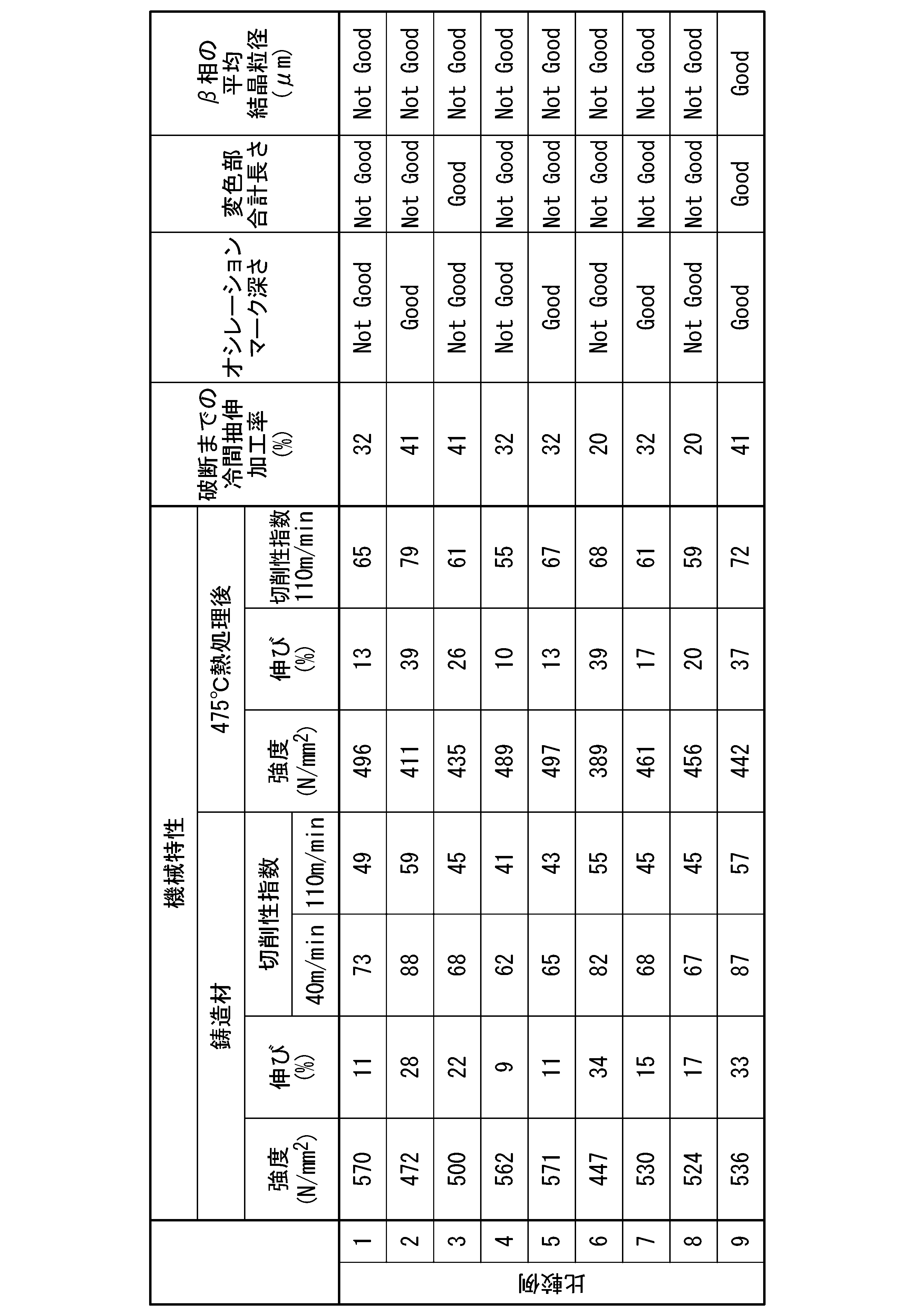
比較例1においては、Cuの含有量が少なく(Znの含有量が多く)、α相とβ相の面積割合においてα相の比率が低く(β相の比率が高く)、破断までの冷間抽出加工率が低く加工性を確保できなかった。また、切削性指数が低く、被削性が不十分であった。さらに、オシレーションマーク深さ、変色部の評価が「Not Good」となった。
比較例2においては、Cuの含有量が多く(Znの含有量が少なく)、γ相の面積率が0.1%を超えており、破断までの冷間抽出加工率が低く加工性を確保できなかった。また、変色部の評価が「Not Good」となった。
比較例2においては、Cuの含有量が多く(Znの含有量が少なく)、γ相の面積率が0.1%を超えており、破断までの冷間抽出加工率が低く加工性を確保できなかった。また、変色部の評価が「Not Good」となった。
比較例3においては、Siの含有量が少なく、破断までの冷間抽出加工率が低く加工性を確保できなかった。また、切削性指数が低く、被削性が不十分であった。さらに、オシレーションマーク深さがの評価が「Not Good」となった。
比較例4においては、Siの含有量が多く、γ相の面積率が0.1%を超えており、破断までの冷間抽出加工率が低く加工性を確保できなかった。また、切削性指数が低く、被削性が不十分であった。さらに、オシレーションマーク深さ、変色部の評価が「Not Good」となった。
比較例4においては、Siの含有量が多く、γ相の面積率が0.1%を超えており、破断までの冷間抽出加工率が低く加工性を確保できなかった。また、切削性指数が低く、被削性が不十分であった。さらに、オシレーションマーク深さ、変色部の評価が「Not Good」となった。
比較例5においては、Pbを含有しておらず、切削性指数が低く、被削性が不十分であった。また、変色部の評価が「Not Good」となった。
比較例6においては、Pbの含有量が多く、強度が低くなった。また、破断までの冷間抽出加工率が低く加工性を確保できなかった。さらに、オシレーションマーク深さ、変色部の評価が「Not Good」となった。
比較例6においては、Pbの含有量が多く、強度が低くなった。また、破断までの冷間抽出加工率が低く加工性を確保できなかった。さらに、オシレーションマーク深さ、変色部の評価が「Not Good」となった。
比較例7においては、Pの含有量が少なく、切削性指数が低く、被削性が不十分であった。また、破断までの冷間抽出加工率が低く加工性を確保できなかった。さらに、変色部の評価が「Not Good」となった。
比較例8においては、Pの含有量が多く、切削性指数が低く、被削性が不十分であった。また、破断までの冷間抽出加工率が低く加工性を確保できなかった。さらに、オシレーションマーク深さ、変色部の評価が「Not Good」となった。
比較例8においては、Pの含有量が多く、切削性指数が低く、被削性が不十分であった。また、破断までの冷間抽出加工率が低く加工性を確保できなかった。さらに、オシレーションマーク深さ、変色部の評価が「Not Good」となった。
これに対して、本発明例によれば、強度および伸びに優れていた。また、切削性指数が高く、被削性に優れていた。さらに、破断までの冷間抽出加工率が高く、加工性を確保できた。また、オシレーションマーク深さ、変色部の評価が「Good」であり、安定して連続鋳造することができた。さらに、熱処理後においても、強度および伸び、被削性に優れていた。
以上、本発明例によれば、強度、伸び、被削性に優れ、かつ、欠陥の少ない高品質なCu-Zn-Si-Pb-P系合金連続鋳造線棒材を提供可能であることが確認された。
本発明によれば、強度、伸び、被削性に優れ、かつ、欠陥の少ない高品質なCu-Zn-Si-Pb-P系合金連続鋳造線棒材を提供することが可能となる。
Claims (12)
- 60.0mass%超え65.0mass%未満のCuと、0.40mass%以上1.20mass%以下の範囲内のSiと、0.002mass%以上0.250mass%以下の範囲内のPbと、0.040mass%以上0.190mass%以下の範囲内のPを含み、任意元素として0.001mass%以上0.100mass%以下のBiを含み、残部がZn及び不純物からなり、前記不純物のうち、Fe,Mn,CoおよびCrの合計含有量が0.450mass%以下であり、かつ、SnおよびAlの合計含有量が0.30mass%以下であり、
鋳造方向に直交する断面において、α相とβ相の面積割合がα:β=40~70:60~30であり、γ相の面積率が0.1%以下であり、粒径10μm以下の微細α相の面積率が30%以上60%以下であることを特徴とするCu-Zn-Si-Pb-P系合金連続鋳造線棒材。 - 引張強度が450MPa以上600MPa以下の範囲内、伸びが12%以上35%以下の範囲内であることを特徴とする請求項1に記載のCu-Zn-Si-Pb-P系合金連続鋳造線棒材。
- ISO分類記号K10の超硬工具を取り付けた旋盤を用い、すくい角:0°、ノーズ半径:0.4mm、逃げ角:6°、切削速度:40m/分、切り込み深さ:1.0mm、送り速度:0.11mm/rev.の条件下(乾式下)で、切削加工した直径14mmの試験材円周上を切削した際に、工具に取り付けられた動力計による計測値から以下の(1)式で算出される切削抵抗が、Zn-59mass%Cu-3mass%Pb-0.2mass%Fe-0.3mass%Sn合金からなる市販快削黄銅棒C3604の切削抵抗を100とした相対値である被削性指数が90以上となることを特徴とする請求項1または請求項2に記載のCu-Zn-Si-Pb-P系合金連続鋳造線棒材。
(1)式:切削抵抗=((主分力)2+(送り分力)2+(背分力)2)1/2 - ISO分類記号K10の超硬工具を取り付けた旋盤を用い、すくい角:0°、ノーズ半径:0.4mm、逃げ角:6°、切削速度:110m/分、切り込み深さ:1.0mm、送り速度:0.21mm/rev.の条件下(乾式下)で、切削加工した直径14mmの試験材円周上を切削した際に、工具に取り付けられた動力計による計測値から以下の(1)式で算出される切削抵抗が、Zn-59mass%Cu-3mass%Pb-0.2mass%Fe-0.3mass%Sn合金からなる市販快削黄銅棒C3604の切削抵抗を100とした相対値である被削性指数が60以上となることを特徴とする請求項1または請求項2に記載のCu-Zn-Si-Pb-P系合金連続鋳造線棒材。
(1)式:切削抵抗=((主分力)2+(送り分力)2+(背分力)2)1/2 - 450℃で120分保持後に空冷する熱処理を実施後において、金属組織の構成相において、γ相の面積率が0.1%以下であり、粒径10μm以下の微細α相の面積率が30%以上60%以下であることを特徴とする請求項1または請求項2に記載のCu-Zn-Si-Pb-P系合金連続鋳造線棒材。
- 475℃で120分保持後に空冷する熱処理を実施後において、引張強度が400MPa以上550MPa以下、伸びが14%以上38%以下であることを特徴とする請求項1または請求項2に記載のCu-Zn-Si-Pb-P系合金連続鋳造線棒材。
- 475℃で120分保持後に空冷する熱処理を実施後において、
ISO分類記号K10の超硬工具を取り付けた旋盤を用い、すくい角:0°、ノーズ半径:0.4mm、逃げ角:6°、切削速度:40m/分、切り込み深さ:1.0mm、送り速度:0.11mm/rev.の条件下(乾式下)で、切削加工した直径14mmの試験材円周上を切削した際に、工具に取り付けられた動力計による計測値から以下の(1)式で算出される切削抵抗が、Zn-59mass%Cu-3mass%Pb-0.2mass%Fe-0.3mass%Sn合金からなる市販快削黄銅棒C3604の切削抵抗を100とした相対値である被削性指数が80以上となることを特徴とする請求項1または請求項2に記載のCu-Zn-Si-Pb-P系合金連続鋳造線棒材。
(1)式:切削抵抗=((主分力)2+(送り分力)2+(背分力)2)1/2 - 475℃で120分保持後に空冷する熱処理を実施後において、
断線する迄の最大可能冷間抽伸加工率が50%以上であることを特徴とする請求項1または請求項2に記載のCu-Zn-Si-Pb-P系合金連続鋳造線棒材。 - 600℃で120分保持後に空冷する熱処理を実施後において、粒径10μm以下の微細α相の面積率が10%以上20%以下であることを特徴とする請求項1または請求項2に記載のCu-Zn-Si-Pb-P系合金連続鋳造線棒材。
- 鋳造方向に直交する断面において、β相の平均結晶粒径が500μm以下で、デンドライトおよび柱状晶が分断された結晶組織を有し、
α相の最大長さの箇所を長軸、長軸に直交する最大長さの箇所を短軸として、長軸長さL1と短軸長さL2との比L1/L2が1以上4以下の範囲内であり、略円形状、楕円形状または多角形状をなすことを特徴とする請求項1または請求項2に記載のCu-Zn-Si-Pb-P系合金連続鋳造線棒材。 - オシレーションマーク深さが50μm未満であることを特徴とする請求項1または請求項2に記載のCu-Zn-Si-Pb-P系合金連続鋳造線棒材。
- 鋳造方向に直交する断面の断面積が12mm2以上227mm2以下の範囲内であることを特徴とする請求項1または請求項2に記載のCu-Zn-Si-Pb-P系合金連続鋳造線棒材。
Applications Claiming Priority (2)
| Application Number | Priority Date | Filing Date | Title |
|---|---|---|---|
| JP2023190352A JP2025077850A (ja) | 2023-11-07 | 2023-11-07 | Cu-Zn-Si-Pb-P系合金連続鋳造線棒材 |
| JP2023-190352 | 2023-11-07 |
Publications (1)
| Publication Number | Publication Date |
|---|---|
| WO2025100166A1 true WO2025100166A1 (ja) | 2025-05-15 |
Family
ID=95695804
Family Applications (1)
| Application Number | Title | Priority Date | Filing Date |
|---|---|---|---|
| PCT/JP2024/036437 Pending WO2025100166A1 (ja) | 2023-11-07 | 2024-10-11 | Cu-Zn-Si-Pb-P系合金連続鋳造線棒材 |
Country Status (2)
| Country | Link |
|---|---|
| JP (1) | JP2025077850A (ja) |
| WO (1) | WO2025100166A1 (ja) |
Citations (3)
| Publication number | Priority date | Publication date | Assignee | Title |
|---|---|---|---|---|
| WO2020261636A1 (ja) * | 2019-06-25 | 2020-12-30 | 三菱マテリアル株式会社 | 快削性銅合金鋳物、及び、快削性銅合金鋳物の製造方法 |
| WO2021225165A1 (ja) * | 2020-05-08 | 2021-11-11 | 三菱マテリアル株式会社 | Cu-Zn-Si系合金の上方引上連続鋳造線材 |
| WO2024228354A1 (ja) * | 2023-05-01 | 2024-11-07 | 三菱マテリアル株式会社 | 快削性銅合金鋳物、及び、快削性銅合金鋳物の製造方法 |
-
2023
- 2023-11-07 JP JP2023190352A patent/JP2025077850A/ja active Pending
-
2024
- 2024-10-11 WO PCT/JP2024/036437 patent/WO2025100166A1/ja active Pending
Patent Citations (4)
| Publication number | Priority date | Publication date | Assignee | Title |
|---|---|---|---|---|
| WO2020261636A1 (ja) * | 2019-06-25 | 2020-12-30 | 三菱マテリアル株式会社 | 快削性銅合金鋳物、及び、快削性銅合金鋳物の製造方法 |
| WO2021117528A1 (ja) * | 2019-06-25 | 2021-06-17 | 三菱マテリアル株式会社 | 快削性銅合金、及び、快削性銅合金の製造方法 |
| WO2021225165A1 (ja) * | 2020-05-08 | 2021-11-11 | 三菱マテリアル株式会社 | Cu-Zn-Si系合金の上方引上連続鋳造線材 |
| WO2024228354A1 (ja) * | 2023-05-01 | 2024-11-07 | 三菱マテリアル株式会社 | 快削性銅合金鋳物、及び、快削性銅合金鋳物の製造方法 |
Also Published As
| Publication number | Publication date |
|---|---|
| JP2025077850A (ja) | 2025-05-19 |
Similar Documents
| Publication | Publication Date | Title |
|---|---|---|
| JP6799305B1 (ja) | 快削性銅合金鋳物、及び、快削性銅合金鋳物の製造方法 | |
| JP4951342B2 (ja) | 銅合金鋳物及びその鋳造方法 | |
| JP5546196B2 (ja) | 時効析出型銅合金、銅合金材料、銅合金部品および銅合金材料の製造方法 | |
| WO2011125264A1 (ja) | 銅合金展伸材、銅合金部品および銅合金展伸材の製造方法 | |
| JP2025527196A (ja) | 銅-亜鉛合金からなる鋳物材料、鋳造生成物を製造するための方法、及び鋳造部品 | |
| WO2024228355A1 (ja) | 快削性銅合金、および、快削性銅合金の製造方法 | |
| WO2025100166A1 (ja) | Cu-Zn-Si-Pb-P系合金連続鋳造線棒材 | |
| JP5856764B2 (ja) | 過共晶アルミニウム−シリコン合金圧延板成形品およびその製造方法 | |
| JP4065763B2 (ja) | 切削性に優れたアルミニウム合金圧延材およびその製造方法 | |
| JP4719731B2 (ja) | 切削性に優れたアルミニウム合金圧延材およびその製造方法 | |
| CN115443343A (zh) | Cu-Zn-Si系合金的上引连续铸造线材 | |
| WO2026094558A1 (ja) | 快削性銅合金鋳物、および、快削性銅合金鋳物の製造方法 | |
| WO2026094557A1 (ja) | 快削性銅合金、および、快削性銅合金の製造方法 | |
| KR100834201B1 (ko) | 결정립이 미세화된 구리기합금주물 | |
| JP2024060760A (ja) | Cu-Zn-Sn系合金の連続鋳造線棒材 |
Legal Events
| Date | Code | Title | Description |
|---|---|---|---|
| 121 | Ep: the epo has been informed by wipo that ep was designated in this application |
Ref document number: 24888464 Country of ref document: EP Kind code of ref document: A1 |