WO2025099956A1 - 制御システム、制御方法および制御プログラム - Google Patents
制御システム、制御方法および制御プログラム Download PDFInfo
- Publication number
- WO2025099956A1 WO2025099956A1 PCT/JP2023/042837 JP2023042837W WO2025099956A1 WO 2025099956 A1 WO2025099956 A1 WO 2025099956A1 JP 2023042837 W JP2023042837 W JP 2023042837W WO 2025099956 A1 WO2025099956 A1 WO 2025099956A1
- Authority
- WO
- WIPO (PCT)
- Prior art keywords
- information
- input
- unit
- model
- learning model
- Prior art date
- Legal status (The legal status is an assumption and is not a legal conclusion. Google has not performed a legal analysis and makes no representation as to the accuracy of the status listed.)
- Pending
Links
Images












Classifications
-
- G—PHYSICS
- G06—COMPUTING OR CALCULATING; COUNTING
- G06F—ELECTRIC DIGITAL DATA PROCESSING
- G06F11/00—Error detection; Error correction; Monitoring
- G06F11/07—Responding to the occurrence of a fault, e.g. fault tolerance
-
- G—PHYSICS
- G06—COMPUTING OR CALCULATING; COUNTING
- G06F—ELECTRIC DIGITAL DATA PROCESSING
- G06F11/00—Error detection; Error correction; Monitoring
- G06F11/30—Monitoring
-
- G—PHYSICS
- G06—COMPUTING OR CALCULATING; COUNTING
- G06N—COMPUTING ARRANGEMENTS BASED ON SPECIFIC COMPUTATIONAL MODELS
- G06N20/00—Machine learning
-
- G—PHYSICS
- G06—COMPUTING OR CALCULATING; COUNTING
- G06N—COMPUTING ARRANGEMENTS BASED ON SPECIFIC COMPUTATIONAL MODELS
- G06N3/00—Computing arrangements based on biological models
- G06N3/02—Neural networks
- G06N3/04—Architecture, e.g. interconnection topology
- G06N3/0475—Generative networks
Definitions
- This disclosure relates to a control system, a control method, and a control program.
- AI artificial intelligence
- generative artificial intelligence an AI capable of generating a wide variety of content
- AI will expand.
- AI will not only be used for tasks within the home, but also in a variety of locations and situations, including in buildings, factories, stations, schools, hospitals and commercial facilities, as well as outdoors, such as on roads, outdoor facilities, and in the sky or at sea.
- Patent Document 1 describes a machining program generation device that uses a large-scale language model to generate a program for controlling a machine.
- work performed by people or objects includes not only work in the real world performed by people or machines, but also work in data space, such as information processing performed by processors such as CPUs (central processing units).
- Examples of operations using objects include the following: - Work using various types of equipment, such as robots, machines, devices, and sensors - Work using various types of mobility, such as cars, trains, buses, aircraft, and ships.
- This work can include work that is referred to, for example, as controlling, processing, machining, instructing, calculating, inputting, outputting, displaying, communicating, testing, manufacturing, converting, generating, measuring, irradiating, emitting, inhaling, dissipating heat, heating, cooling, recording, reading, shaping, driving, moving, transporting, flying, investigating, monitoring, measuring, and extracting.
- Examples of tasks performed by humans include the following: - Operation performed by humans with other humans or other living things - Operation performed by humans with various devices This operation can include, for example, operation known as communicating, watching, checking, operating, monitoring, instructing, mediating, interpreting, etc.
- model maintainability can be an issue, as the model needs to be retrained every time equipment is changed or added.
- the purpose of this disclosure is to use learning models to improve the efficiency or performance of work performed by people or objects.
- the control system comprises: an input interface that receives input information input from a source and inputs the input information into a learning model unit; a control determination unit that specifies a precondition for the learning model unit to generate response information in accordance with the input information previously input from the source; and an output interface that accepts response information generated by the learning model unit in response to the input information input by the input interface in accordance with the preconditions specified by the control determination unit, and outputs the response information to the sender.
- the present disclosure by utilizing a learning model, it is possible to improve the efficiency or performance of work performed by people or objects. In particular, it is possible to improve the efficiency or performance of response work that returns a response to information transmitted from a source.
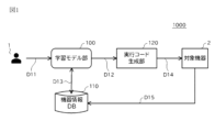
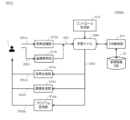
- FIG. 1 is a configuration diagram illustrating an example of a control system according to a first embodiment.
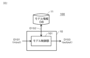
- FIG. 2 is an explanatory diagram showing an example of the configuration of a learning model unit.
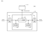
- FIG. 13 is an explanatory diagram showing another example of the configuration of the learning model unit.
- FIG. 13 is an explanatory diagram showing another example of the configuration of the learning model unit.
- FIG. 2 is a configuration diagram showing an example of an information processing device that is the operating environment of a control unit including a learning model unit.
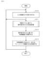
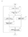
- FIG. 11 is an explanatory diagram showing an example of model learning in a model generation unit. 4 is a flowchart showing an example of the operation of the control system according to the first embodiment;
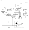
- FIG. 11 is a configuration diagram showing another example of the control system according to the first embodiment.
- FIG. 1 is a configuration diagram illustrating an example of a control system according to a first embodiment.
- FIG. 2 is an explanatory diagram showing an example of the configuration of a learning model unit.
- FIG. 13
- FIG. 11 is a configuration diagram showing another example of the control system according to the first embodiment.
- FIG. 11 is a configuration diagram showing another example of the control system according to the first embodiment.
- FIG. 11 is a configuration diagram illustrating an example of a control system according to a second embodiment.
- FIG. 11 is a configuration diagram showing another example of the control system according to the second embodiment.
- 13 is a flowchart showing an example of the operation of the control system according to the second embodiment.
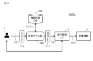
- FIG. 13 is a configuration diagram showing another example of the control system according to the third embodiment.
- FIG. 13 is a flowchart showing an operation example of a modified example according to the third embodiment.
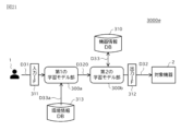
- FIG. 13 is a configuration diagram showing another example of the control system according to the third embodiment.
- FIG. 13 is a configuration diagram showing another example of the control system according to the third embodiment.
- FIG. 13 is a configuration diagram showing another example of the control system according to the third embodiment.
- FIG. 13 is a configuration diagram showing another example of the control system according to the third embodiment.
- 13 is a flowchart showing an operation example of a modified example according to the third embodiment.
- FIG. 13 is a configuration diagram illustrating an example of a control system according to a fourth embodiment. 13 is a flowchart showing an example of the operation of the control system according to the fourth embodiment.
- FIG. 13 is a configuration diagram showing another example of the control system according to the third embodiment.
- FIG. 13 is a configuration diagram showing another example of the control system according to the third embodiment.
- 13 is a flowchart showing an example of the operation of the control system
- FIG. 13 is a configuration diagram showing another example of the control system according to the fourth embodiment. 13 is a flowchart showing an operation example of a modified example according to the fourth embodiment.
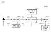
- FIG. 13 is a configuration diagram illustrating an example of a control system according to a fifth embodiment. 13 is a flowchart showing an example of the operation of the control system according to the fifth embodiment.
- FIG. 13 is a configuration diagram showing another example of the control system according to the fifth embodiment.
- 5 is a diagram illustrating an example of a determination method of a true/false determination unit 515.
- FIG. FIG. 13 is a configuration diagram showing another example of the control system according to the fifth embodiment.
- FIG. 13 is a configuration diagram showing another example of the control system according to the fifth embodiment.
- FIG. 13 is a configuration diagram showing another example of the control system according to the fifth embodiment.
- FIG. 13 is a configuration diagram showing another example of the control system according to the fifth embodiment.
- FIG. 13 is a configuration diagram showing another example of the control system according to the fifth embodiment.
- FIG. 13 is a configuration diagram showing another example of the control system according to the fifth embodiment.
- FIG. 13 is a configuration diagram showing another example of the control system according to the fifth embodiment.
- Embodiment 1 an example will be described in which a learning model is used to assist in the task of generating code for a target device.
- FIG. 1 is a configuration diagram showing an example of a control system 1000 according to the first embodiment.
- the control system 1000 shown in FIG. 1 is a control system for controlling equipment using a learning model, and includes a learning model unit 100, an equipment information storage unit 110 (referred to as equipment information DB in the figure), and an execution code generation unit 120.
- FIG. 1 shows a user 1 and a target device 2, these may also be included in the control system 1000. In that case, “user 1" may be read as “user terminal 1.” This also applies to the other embodiments.
- the learning model unit 100 When input information D11 is input, the learning model unit 100 outputs a control description D12.When input information D11 is input, the learning model unit 100 outputs a control description D12 based on model information D102, which will be described later.
- the learning model unit 100 is a model and its operating environment configured to output a control description D12 corresponding to the input information D11 when the input information D11 is input.
- the learning model unit 100 may also be a model and its operating environment configured to generate and output a control description D12 based on the input information D11, device information D13, and/or other information that can be referenced in the learning model unit 100 (such as model reference information D104 described below) when the input information D11 is input.
- the input information D11 includes information indicating the control content requested for the target device 2.
- the input information D11 may be, for example, text, images, audio, or a combination thereof indicating the control content for the target device 2.
- the input information D11 may be, for example, text, images, audio, or a combination thereof indicating a plurality of control contents for the target device 2.
- the input information D11 may also include information indicating the content of control that is performed successively in time, and in that case, may be time-series data of a predetermined data structure including text, images, audio, or a combination thereof indicating the control content as described above. It is assumed that the way in which the control content is indicated matches the input format of the model used by the learning model unit 100, but this is not limited to cases where error processing, correction processing, or conversion processing is included in the stage preceding the learning model unit 100.
- An example of a method of indicating the control content in the input information D11 is to specify the control to be performed on the target device 2, and then specify the parameter values for performing the control or the state after the control.
- the input information D11 may include, for example, information specifying the control and information indicating the parameter values for performing the control or the state after the control.
- the parameter values for performing the control may include, for example, values related to the type of control (ON/OFF, etc.), direction, amount, and time.
- Examples of the control content include "turn on function X" for a programmable logic controller (PLC), "move the tip to point A" for a robot arm, and “lower the set temperature by 1 degree” for an air conditioner.
- examples of a method of indicating the control content in the input information D11 include a method using various information such as a document string (docstring) that explains the specifications of a function, a specification, or a specification, design document, operation command, control code, source code, etc. that is applied to other devices such as other models.
- a document string (docstring) that explains the specifications of a function, a specification, or a specification, design document, operation command, control code, source code, etc.
- the input information D11 can include not only information directly indicating the control contents for the target device 2, but also information indirectly indicating the operation contents corresponding to the control contents, or the words and actions of the user 1, an image of the target device 2, etc.
- the user 1's words such as "It's hot” or the user 1's behavior of feeling hot, such as wiping sweat, rolling up sleeves, and raising hands, can be used to indicate the control contents related to the temperature control of the air conditioner.
- the input information D11 can be information such as text, audio, or images indicating the user 1's remarks, or images (videos) indicating the user 1's behavior.
- control content relating to the arm control of a robotic device can be the posture of the robotic device after control, information specifying the destination point of a specified part, or information indicating an imitation of the robot's movements by a person or other object (a simulator that simulates the movements of the robot, including objects on a screen) or an instruction to the robot (an instruction to an action by a gesture such as pointing).
- the format of the input information D11 is not particularly limited.
- the information may be text, an image, a voice, data written in a specified design language, a control description (including source code and information written in a specified programming platform language), information written in other platform languages, control instructions (including control commands, control signals, control codes, and controller commands), or execution codes. These pieces of information may be combined as appropriate.
- text when used without any particular distinction, it may include, in addition to natural language expressed in text, data written in a specified design language that cannot be distinguished by humans, control descriptions (including source code and information written in a specified programming platform language), information written in other platform languages, control instructions (including control commands, control signals, control codes, and controller commands), and data that can be distinguished by machines, such as execution codes, expressed in text.
- the control description D12 includes information about control written in a predetermined format that can be recognized by the downstream execution code generation unit 120.
- the control description D12 is, for example, source code written in a predetermined programming language.
- the control description D12 may also be, for example, a group of commands written in a format (platform language) that is handled by a predetermined programming platform.
- the predetermined programming platform may include a no-code programming platform and a low-code programming platform.
- the device information storage unit 110 stores device information D13, which is information related to the target device 2.
- the device information D13 may include, for example, information indicating the function, performance, structure, dimensions, operation and/or control method of the target device 2.
- the device information D13 may also include, for example, information related to the program used to control the target device 2.
- the device information D13 may be, for example, a digitized version of the manual or instruction manual for the target device 2.
- the digitization here includes digitization into text, image data, digitization by voice reading, and combinations of these.
- the device information D13 is used, for example, as additional information when the learning model unit 100 outputs the control description D12.
- the device information D13 may include information indicating the state of the target device 2.
- the information indicating the state of the target device 2 may include not only the current state of the target device 2 but also information indicating past states.
- the device information D13 may include time-series data of a predetermined data structure indicating the state of the target device 2.
- the information indicating the state of the target device 2 may be, for example, information output from the target device 2, or information input by the user 1 or another device.
- the information indicating the state of the target device 2 may include various types of information output from the target device 2 (for example, error information, log information, notification information, etc.).
- the information indicating the state of the target device 2 may be referred to as state information D15.
- the execution code generation unit 120 When the control description D12 is input, the execution code generation unit 120 generates and outputs execution code D14, which is code executable by the target device 2, based on the control description D12.
- the execution code D14 may be, for example, a group of codes written in machine language.
- the execution code D14 includes, for example, information used when the target device 2 actually performs control.
- the execution code D14 may be, for example, information relating to control written in a format that can be identified by the target device 2.
- the execution code generation unit 120 may be, for example, a compiler that converts the control description D12 into the execution code D14.
- the execution code D14 output from the execution code generation unit 120 is input to the target device 2.
- the target device 2 operates according to the execution code D14 output from the execution code generation unit 120.
- the execution code D14 may be input to the target device 2 directly from the execution code generation unit 120, or may be input indirectly, such as via a communication network, another device (a server, various conversion devices, etc.), or by hand.
- the target device 2 is a device that can receive and actually execute the execution code D14, but this does not apply if an interface that allows the target device 2 to read the execution code, such as a writing device, is included between the target device 2 and the target device 2.
- the target device 2 is, for example, a PLC, a processing machine, a robot, a radar, a sensor, a camera, a projector, or a communication device.
- the target device 2 may also be, for example, an air conditioner, a refrigerator, a television, a light, or a washing machine.
- the target device 2 may also be, for example, an elevator, mobility, a conveying device, or other machine, or a control device that controls such a machine.
- the target device 2 may also be a device that operates in a power generation/transformation/storage plant, a water treatment plant, or the like, or a control device that controls other equipment. If the control description D12 is in an interpreter language and the target device 2 is a device that can receive the control description D12 and execute it as is, the execution code generation unit 120 is omitted.
- FIG. 2 is an explanatory diagram showing an example of the configuration of the learning model unit 100.
- the learning model unit 100 may include a model control unit 101 that operates on the information processing device 10, and a model information storage unit 11 (referred to as model information DB in the figure) that stores model information D102.
- the model information storage unit 11 may be composed of multiple databases connected via a network.
- the model information D102 includes model information.
- the model information D102 may include, for example, information indicating the correlation between the model input data D101 and the model output data D103.
- the model information D102 may also include, for example, information indicating candidates for the model output data D103.
- the model information D102 may further include, for example, information indicating candidates for the model output data D103 and information indicating the relationships between these candidates.
- the model information D102 may include model parameters, which are information that specifies the behavior of the learning model, such as constraint conditions, weighting variables, and evaluation functions.
- the model may be a model that has been machine-learned, for example, by supervised learning, reinforcement learning, or unsupervised learning.
- the model may be a model that has been obtained by performing learning according to, for example, deep learning, genetic programs, functional logic programs, or other known algorithms or methods.
- the model may also be a model called, for example, a Neural Network (NN) model, a Convolutional Neural Network (CNN) model, a Recurrent Neural Network (RNN), a Variational Autoencoder (VAE), a Generative Adversarial Networks (GAN), a Diffusion model, a Transformer model, a Large Language Model (LLM), a Visual Language Model (VLM), a Bidirectional Encoder Representations from Transformers (BERT), a Generative Pre-trained Transformer (GPT), or a Contrastive Language Image Pre-training (CLIP).
- the model may also be a rule-based model that obtains an output result by referencing a predetermined table or making a decision based on a predetermined condition.
- LLM, VLM, BERT, and GPT are included in the Transformer model.
- the Transformer model is included in the NN model.
- the learning algorithm and model may be a combination of multiple types.
- the model also includes what is called a multimodal model that is learned by combining multiple different types of data.
- model control unit 101 When the model control unit 101 receives model input data D101, it outputs model output data D103 corresponding to the model input data D101 based on the model input data D101 and model information D102. When the model control unit 101 receives model input data D101, it outputs model output data D103 corresponding to the model input data D101, for example, using a model indicated by the model information D102.
- the model control unit 101 is realized, for example, by a CPU that operates according to a program provided in the information processing device 10.
- the learning model unit 100 may be referred to as an artificial intelligence unit.
- the artificial intelligence unit refers to an AI equipped with intelligent functions such as inference and judgment and its operating environment. Therefore, the model control unit 101 may include an AI equipped with intelligent functions such as inference and judgment and its operating environment.
- the model control unit 101 may be, for example, an AI equipped with a learning model such as that described above and its operating environment.
- the model control unit 101 may be one element (module) of the control unit 104 provided in the information processing device 10.
- the learning model unit 100 may further include a reference information storage unit 12 (referred to as reference information DB12 in the figure) that stores model reference information D104.
- the reference information storage unit 12 may be composed of multiple databases connected via a network. The same applies to other storage units (e.g., device information storage unit, etc.) described below.
- the model reference information D104 is information that the model control unit 101 references to in order to output model output data.
- the model reference information D104 may include a history of model input data that was previously input and/or a history of model output data that was previously output.
- the model reference information D104 may also include information that associates features included in past inputs with features included in the output performed for those inputs.
- the model reference information D104 may also include evaluation information on the results output for past inputs.
- the model reference information D104 may also include information related to an expression or concept included in the model input data D101.
- the model reference information D104 may, for example, include information that associates a specific expression or concept that may be included in the model input data D101 with another expression or concept related to that expression or concept.
- the other expression or concept related to a certain expression or concept includes an expression or concept that is more specific than the certain expression or concept, and another expression or concept that is evoked based on the certain expression or concept.
- the model reference information D104 may, for example, include information that associates a specific expression or concept that may be included in the model input data D101 with an expression or concept related to that expression or concept.
- the model reference information D104 may, for example, include information that associates a specific expression or concept that may be included in the model input data D101 with information related to that expression or concept.
- the model reference information D104 may, for example, include information that associates a search key extracted from an expression or concept that may be included in the model input data D101 with a value.
- the model reference information D104 may include information for so-called grounding.
- the model reference information D104 may also include a so-called knowledge graph that describes real-world entities and the relationships between them. In a knowledge graph, various pieces of information are systematically linked and represented in a graph structure.
- the model reference information D104 may also include information for so-called attention.
- the model reference information D104 may include information indicating the correlation between an expression or concept that may be included in the model input data D101 and another expression or concept.
- the model reference information D104 may also include a feature map in which key information extracted from an expression or concept that may be included in the model output data D103 linked to an expression or concept that may be included in the model input data D101 is used as a feature.
- the model reference information D104 may also include information that associates a query extracted from an expression or concept that may be included in the model input data D101 with key information for search corresponding to that query.
- model control unit 101 when the model control unit 101 receives model input data D101, it outputs model output data D103 based on the model input data D101, model information D102, and model reference information D104.
- the learning model unit 100 can also include a search engine that searches for the model reference information D104 or an interface with the search engine.
- the search range of the search engine can be an external network or a specific network.
- a database e.g., a device information DB, etc.
- the control system of the present disclosure can be used as one of the external networks or specific networks.
- the term "learning model” may refer to a computer algorithm that outputs some kind of information based on learned information in response to input information, or to the learned information itself.
- a “learning model” in an operating environment it often refers to an actual program that operates such a computer algorithm and the operating environment. In this disclosure, the latter is adopted, and a model that actually operates based on information stored in model information D102, etc., is called a "learning model” to distinguish it from a simple algorithm or a group of learned information.
- the control system according to this disclosure includes a learning model unit (particularly model control unit 101) that corresponds to such a learning model. Therefore, hereinafter, when referring to a “learning model” in the explanation of the control system, it refers to the learning model unit or particularly the model control unit 101.
- FIG. 4 is an explanatory diagram showing another example configuration of the learning model unit 100.
- the learning model unit 100 may include an input unit 102, an output unit 103, and a control unit 104.
- the input unit 102 accepts the model input data D101.
- the input unit 102 may accept the model input data D101 input by the user 1 or the like.
- the input unit 102 may accept the model input data D101 constituting the time series data. At this time, the input unit 102 may sequentially accept the model input data D101 constituting the time series data, or may accept the model input data D101 that has been buffered to a certain extent.
- the input unit 102 may also accept the model input data D101 input from a plurality of input sources.
- the input unit 102 may accept the model input data D101 to which information on the input source (e.g., a user identifier, user attribute information, etc.) has been added, or the input unit 102 may determine the input source and add the information on the input source to the model input data D101 before accepting it, or may accept it without doing anything in particular.
- the input unit 102 is realized, for example, by various input devices (for example, a pointing device, a keyboard, a voice input device, an image input device, a data reading device, a data input device compatible with various communication interfaces, etc.) provided in the information processing device 10.
- the input unit 102 may be realized by an external device of the information processing device 10. In that case, it is sufficient for the information processing device 10 to include an interface with the input unit 102.
- the output unit 103 outputs an object generated by the control unit 104.
- the object includes the model output data D103 or data generated from the model output data D103. If the object generated by the control unit 104 includes information for multiple output destinations, the output unit 103 may output the object to multiple output destinations. In this case, the output unit 103 may output the same data to multiple output destinations, or may output different data for each output destination.
- the output unit 103 is realized, for example, by various output devices (for example, a display device, an audio output device, an image output device, a data writing device, a data output device compatible with various communication interfaces, etc.) provided in the information processing device 10.
- the output unit 103 may be realized by an external device of the information processing device 10. In that case, the information processing device 10 only needs to include an interface with the output unit 103.
- the control unit 104 operates on the information processing device 10 and includes a pre-processing unit 105 and a post-processing unit 106 in addition to the model control unit 101 described above.
- the pre-processing unit 105 performs processing to improve the accuracy of the object generated by the control unit 104.
- the pre-processing unit 105 may, for example, add, change, or delete elements from the model input data D101, or convert (including process) the data.
- the preprocessing unit 105 may change elements (including addition and deletion) or convert data (including processing) for the model input data D101.
- Changing elements or converting data (including processing) includes not only changing the data format, but also changing the expression or concept represented by the data.
- the data changed by the preprocessing unit 105 is input as model input data D101 to the model control unit 101 at the subsequent stage.
- the processing performed by the preprocessing unit 105 includes so-called prompt shaping for the model control unit 101.
- the pre-processing unit 105 may, for example, perform a process of breaking down the model input data D101 into predetermined unit data.
- the pre-processing unit 105 may also, for example, perform a process of integrating a plurality of model input data D101.
- the pre-processing unit 105 may break down the model input data D101 into predetermined unit data and then change the elements or convert the data, or may integrate a plurality of model input data D101 and then change the elements or convert the data.
- the post-processing unit 106 corrects the object when there is a problem with the object generated by the control unit 104 (particularly the model control unit 101), for example.
- the post-processing unit 106 may determine whether there is a problem with the object, for example, by using the above-mentioned knowledge graph. For example, it may compare the similarity between the relationship shown by the knowledge graph and the relationship between the expression or concept included in the model input data and the expression or concept included in the model output data, and/or the relationship between the expressions or concepts included in the model output data, and determine that there is a problem with the object when it is away from the relationship shown by the knowledge graph by a predetermined distance or more.
- components other than the model control unit 101 are not essential, and you can choose whether or not to implement them as appropriate.
- model information D102 and other information used by the learning model may be prepared in advance, or may be obtained via a communication network as necessary.
- FIG. 5 is a configuration diagram showing another example of an information processing device 10 as an operating environment for a control unit 104 including a learning model unit 100.
- the information processing device 10 shown in FIG. 5 may include a control unit 104a including a learning model unit 100 (particularly a model control unit 101), an input processing unit 201, an output confirmation unit 202, and a correction confirmation unit 203.
- the input processing unit 201 receives input information D11 from an input source 1a such as a user 1.
- the input processing unit 201 also outputs the received input information D11 to the learning model unit 100 as model input data D101.
- the input processing unit 201 may output, for example, the input information D11 with modified elements or converted data as the model input data D101.
- the input processing unit 201 may, for example, remove noise from the input information D11.
- the input processing unit 201 may convert the information into quantitative information.
- the input processing unit 201 may correct the amount in accordance with the device that is the target of the request for the input information D11 and its operating environment.
- the input processing unit 201 may perform so-called grounding processing, that is, change the expression or concept indicated by the input information D11 into a more concrete expression or concept.
- the input processing unit 201 may also return a query to the input source when the input information D11 contains unclear or uncertain information. As a query, the input processing unit 201 may output, for example, a message to confirm the input contents, a message proposing a revision to the input information D11, or a message requesting re-input of the input information D11 with a different state or expression.
- the revision proposal for the input information D11 may also be generated by the revision confirmation unit 203 described below.
- supplementary information D18 information indicating revision, addition, or cancellation of the contents of the input/output data of the learning model after input/output may be referred to as supplementary information D18.
- the revision proposal is an example of supplementary information D18.
- the output confirmation unit 202 performs a simulation that simulates the control and state of the target device 2 based on the model output data D103 output from the learning model unit 100.
- the output confirmation unit 202 may perform a simulation after converting the model output data D103 into control information that matches a predetermined simulator (not shown) that can simulate the control and state of the target device 2.
- the output confirmation unit 202 may have the function of a simulator.
- the output confirmation unit 202 may use information acquired from an output destination 2a of the model output data D103.
- the output destination 2a includes an output destination of information generated from the model output data D103.
- the information acquired from the output destination 2a may include, for example, state information D15 and/or feedback information D16, which will be described later.
- the output confirmation unit 202 may, for example, confirm the state of the target device 2, the state of the system including the target device 2, and/or the state of the work that the target device 2 has. Furthermore, before checking the operation, the output confirmation unit 202 may generate and display a human-understandable intermediate product for the model output data D103 or information generated based on it. Examples of intermediate products include source code for a control program, and an operation image of the controller of the target device 2 for an operation command to the target device 2. Furthermore, the output confirmation unit 202 may display the results of the simulation together with a reliability index of the learning model.
- a human can evaluate the results of each input to the learning model, accumulating the results, and providing an evaluation network that has learned the input and evaluation results.
- the input to the learning model can also be input to the above-mentioned evaluation network, and the output result can be used as the reliability index.
- a learning device that clusters the output of the learning model during pre-learning, etc., may be provided, and when the learning model is used, the output of the learning model may also be input to the above-mentioned learning device, and the result of the clustering may be used as a reliability index.
- a human evaluation of the results of each input to the learning model can be accumulated, and an evaluation network can be provided that learns the features of the input with high evaluation results.
- the input of the learning model can also be input to the above-mentioned evaluation network, and the similarity between the features that are the output result and the features of the learning result can be used as a reliability index.
- a learning device may be provided that accumulates the results of a human evaluation of each input to the learning model, and clusters the learning model inputs with high evaluation results.
- the learning model input may also be input to the learning device, and the clustering results may be used as a reliability index.
- the correction confirmation unit 203 uses the results of the simulation performed by the output confirmation unit 202 to determine the validity of the model output data D103 and/or the model input data D101. For example, the correction confirmation unit 203 may compare the state of the target device 2 shown in the simulation result with the state of the target device 2 specified by the input information D11, the model output data D103, and/or the model input data D101 to determine whether correct control is being performed, thereby determining the validity of the model output data D103 and/or the model input data D101. The correction confirmation unit 203 may determine that correct control is being performed when the state of the target device 2 shown in the simulation result matches the state of the target device 2 specified by the model output data D103 and/or the model input data D101.
- the state of the target device 2 compared here is not limited to one.
- the correction confirmation unit 203 may also determine the validity of the model output data D103 and/or the model input data D101 by, for example, checking whether the state or control trajectory of the target device 2 shown in the simulation result matches the control shown in the input information D11, or whether it does not contain any content that is prohibited in advance.
- the correction confirmation unit 203 may also present the simulation results to the input source 1a of the input information D11 and ask for a response as to whether the desired control is being performed, thereby determining the validity of the model output data D103 and/or the model input data D101.
- the correction confirmation unit 203 may correct the model input data D101. In addition, instead of correcting the model input data D101, the correction confirmation unit 203 may generate supplemental information D18 for the input information D11 and output it to the input source 1a.
- the control system 1000 may have, for example, any of the configurations shown in Figures 1 to 5 as the operating environment of the learning model unit 100. As with the learning model unit 100, in this case too, some or all of the configuration may be internal or external to the control system 1000.
- FIG. 6 is an explanatory diagram showing an example of model learning.
- the model information D102 may be generated by the model generation unit 107 through machine learning using the model learning data D105, for example.
- the model generation unit 107 is a processing unit that generates or updates model information D102 based on the input model learning data D105 according to a predetermined algorithm.
- the model generation unit 107 is realized, for example, by a CPU that operates according to a program provided in the information processing device 20.
- the algorithm followed by the model generation unit 107 may be a machine learning algorithm corresponding to the learning model, such as supervised learning, reinforcement learning, or unsupervised learning, or it may be deep learning, a genetic program, a functional logic program, or other known algorithm.
- the model generation unit 107 may further generate or update model information D102 for the input model learning data D105 based on model reference information D104.
- the model generation unit 107 may further generate or update model information D102 for the input model learning data D105 based on model output data D103 from the model control unit 101.
- the model learning data D105 is not particularly limited.
- the model learning data D105 may include candidates for model input data D101 that can be input and candidates for model output data D103 corresponding thereto.
- the model learning data D105 may also include model input data D101 that is actually input and/or model output data D103 that is actually output. Feedback control can be performed by appropriately using the actual model input data D101 and/or model output data D103.
- the model learning data D105 may also include information acquired from a device or a processing unit provided in a system in which the learning model actually operates.
- the model information D102 generated or updated by the model generation unit 107 is stored in the model information storage unit 11 and is provided to the model control unit 101. Alternatively, the model generation unit 107 can output the model information D102 directly to the model control unit 101.
- the model generation unit 107 may generate model information D102 using the input model learning data D105 by pre-learning, for example, before the model control unit 101 uses the model information D102, and store the model information in the model information storage unit 11.
- the update of the model information D102 by the model generation unit 107 may be a process called FineTune.
- the model generation unit 107 may be included in the control system 1000, or may be included in a system separate from the control system 1000.
- the learning model unit 100 is shown separately from the device information storage unit 110 and the device information D13, but the device information storage unit 110 and the device information D13 may be part of the learning model unit 100. That is, the learning model unit 100 may include the device information storage unit 110 and the device information D13.
- the learning model unit 100 may include the device information storage unit 110 as one of the reference information storage units 12 described below.
- the device information D13 may be used in the model learning phase in which the model used by the learning model unit 100 learns, so that the device information D13 is pre-integrated into the model. In that case, the device information storage unit 110 may be omitted.
- part or all of the learning model unit 100 may be an internal configuration of the control system 1000, or may be an external configuration of the control system 1000.
- the control system 1000 only needs to have an interface capable of exchanging information with an external system that has part or all of the learning model unit 100, instead of part or all of the learning model unit 100.
- the control system 1000 may have the model information storage unit 11, which is called the core of the learning model, as an external configuration.
- the control system 1000 may have the model information storage unit 11, which is called the core of the learning model, and the model control unit 101, which is responsible for the model algorithm, as external configurations.
- the model processing unit corresponds to the above-mentioned information processing device 10, the control unit 104, or the control unit 104a other than the model control unit 101.
- the model processing unit may be realized by an OS (Operating System) or a prompt application (and a control unit that is considered to be the operating environment) that runs on the information processing device 10 and calls the learning model application.
- the model processing unit may be realized by a browser or a client application (and a control unit that is considered to be the operating environment) that runs on the information processing device 10.
- the input information D11 corresponds to the model input data D101.
- the control description D12 corresponds to the model output data D103.
- the learning model unit 100 (particularly the model control unit 101) may be configured to, for example, upon receiving the input information D11, output the control description D12 corresponding to the input information D11 based on the model information D102 and, if necessary, the model reference information D104.
- the model generation unit 107 provided corresponding to the learning model unit 100 may perform machine learning using, for example, model learning data D105 including candidates for input information D11 that may be input to the model control unit 101, to generate or update the model information D102.
- the model generation unit 107 may perform machine learning using, for example, model learning data D105 including candidates for input information D11 that may be input to the model control unit 101 and candidates for the corresponding control description D12, to generate or update the model information D102.
- the learning model unit 100 may be, for example, a language learning model such as an LLM that receives input of natural language and obtains an output result, and its operating environment.
- the learning model unit 100 may also be, for example, an image learning model such as a VLM that receives input of an image and obtains an output result, and its operating environment.
- the learning model unit 100 may also be, for example, a multimodal model that receives input of natural language and an image and obtains an output result, and its operating environment.
- the input information D11 may be input in the form of text data, image data, a combination of text data and image data, or a data format that can be converted into any of these (such as audio data or a video that is a combination of audio data and image data).
- the learning models used in this embodiment are not limited to the above-mentioned models.
- model input data based on the input information D11 may include the input information D11 itself, the input information D11 converted into a format that matches the input of the learning model, and a supplement to the input information D11.
- second information based on the model output data may include the model output data itself, the model output data converted into a format that matches the input of the output destination, and a supplement to the model output data. The same applies to the relationship between the input/output information and the model input/output data in the other embodiments.
- Figure 7 is a flowchart showing an example of the operation of the control system 1000.
- the control system 1000 receives input information D11 (step S110).
- the input unit 102 or the input processing unit 201 described above may receive the input information D11.
- the received input information D11 is input to the learning model unit 100 as model input data D101.
- the control system 1000 may receive a plurality of pieces of input information D11.
- the control system 1000 may also receive input information D11 that better matches the needs of the user 1 interactively with the user 1, i.e., by repeatedly inputting and outputting information related to the input information D11 between the control system 1 and the user 1.
- step S111 the learning model unit 100 generates and outputs a control description D12 corresponding to the input information D11 that has been input.
- the learning model unit 100 (more specifically, the model control unit 101) outputs the control description D12 corresponding to the input information D11 based on the model information D102 and the input input information D11, as well as model reference information D104 including device information D13 as necessary.
- the learning model unit 100 may generate the control description D12 of text data from the input information D11 that has been input, for example, using a learning model capable of generating text data.
- the learning model unit 100 may further add, change or delete elements, or convert (including processing) data from the input information D11, before processing by the model control unit 101, in order to improve the accuracy of the control description D12. Also, in step S111, the learning model unit 100 (more specifically, the post-processing unit 106) may further determine whether there is a problem with the control description D12 after processing by the model control unit 101, and perform processing to correct the control description D12 if it is determined that there is a problem.
- the control description D12 output from the learning model unit 100 is input to the execution code generation unit 120.
- the execution code generation unit 120 generates the execution code D14 based on the input control description D12 (step S112).
- the execution code D14 generated by the execution code generation unit 120 is input to the target device 2 (step S113).
- the execution code D14 may be input to the target device 2 directly from the control system 1000 (more specifically, the execution code generation unit 120), or may be input indirectly via a communication network, another device (a server, various conversion devices, etc.), or by human hands.
- the target device 2 operates according to the input execution code D14.
- the control system 1000 may acquire state information D15 (step S114).
- the acquired state information D15 is stored in the device information storage unit 110 as part of the device information D13, for example.
- the control system 1000 may use the acquired state information D15 to update the device information D13 stored in the device information storage unit 110.
- the control system 1000 may also output the acquired state information D15 as information indicating the control result to the user 1, the learning model unit 100, or another device not shown. Note that if the control system 1000 does not use the state information D15, the process of step S114 may be omitted.
- the control system 1000 may repeat the processing of steps S110 to S114 multiple times (e.g., until the desired control of the target device 2 is completed).
- the control system 1000 may output the control description D12 to an operation terminal or the like of the user 1, so that the user 1 can confirm the contents and then execute subsequent processing (such as code generation by the execution code generation unit 120) according to the operation of the user 1.
- the state information D15 input to the learning model unit 100 is used, for example, for additional learning of the learning model unit 100.
- the learning model unit 100 may update the model information D102 and/or the model reference information D104, for example, based on the input state information D15.
- the execution code D14 can be generated from the input information D11 input by the user 1 without the user 1 creating the control description D12, thereby improving the efficiency of the work of controlling the target device 2.
- the input information D11 may be text, an image, a sound, or a combination thereof that explicitly or implicitly indicates the control content for the target device 2, so that the work of controlling the target device 2 can be made more efficient while further reducing the effort required for inputting the input information D11.
- control description D12 can be generated from the input information D11 using a learning model, so that even if the user 1 does not know information for controlling the target device 2, such as detailed specifications of the target device 2 or specifications of the control description D12, the control description D12 corresponding to the input information D11 can be generated, and high performance can be achieved in the operation of controlling the target device 2.
- high performance in the operation of controlling the target device 2 also includes high precision in controlling the target device 2.
- the state information D15 acquired after controlling the target device 2 based on the input information D11 can be used to generate the next control description D12, etc., thereby making it possible to further improve the performance of the task of controlling the target device 2.
- the control system 1000 may control multiple target devices 2.
- the input information D11 may include information capable of identifying the target device 2, or the input side to the learning model unit 100 (input unit 102, preprocessing unit 105, input processing unit 201) may perform processing to identify the target device 2 based on the input information D11, or the learning model unit 100 may output control content in which the target device 2 has been identified as a result of learning.
- FIG. 8 is a configuration diagram showing an example of a control system 1000a which is a modified example of the control system 1000 according to the present embodiment. Note that the same elements as those in the control system 1000 are given the same reference numerals and description thereof will be omitted.
- the output from the learning model unit 100 is confirmed by the user 1 and then input to the downstream execution code generation unit 120.
- the user 1 can check the control description D12 output from the learning model unit 100 and input the input information D11 based on the check result.
- the user 1 can also check the feedback information D16 from the execution code generation unit 120 and/or the target device 2 in addition to the control description D12 output from the learning model unit 100 and input the input information D11 based on the check result.
- the user 1 can input the input information D11 of new contents, as well as the input information D11 indicating the correction, addition, or cancellation of the contents already input.
- the input information D11 can include a command for the learning model unit 100.
- the user 1 can input, as the input information D11, a command for removing a defect included in the input information D11 or a defect included in the output control description D12, together with the feedback information D16.
- the command for removing the defect also includes an input for finding the cause of the defect and a method for solving the defect.
- the feedback information D16 may include a response to a request returned from a processing unit downstream of the learning model unit 100 when control is requested from the processing unit.
- the feedback information D16 may also include information obtained from a processing unit downstream of the learning model unit 100 after control is requested.
- the feedback information D16 may include a response to the request returned from the execution code generation unit 120 when the control description D12 is input to the execution code generation unit 120 and a request is made to generate the control description D12.
- the feedback information D16 may also include a response to the request returned from the target device 2 when the execution code D14 is input to the target device 2 and a request is made to execute the code.
- the feedback information D16 may include state information D15.
- the feedback information D16 may be output directly to the user 1, or may be output to the user 1 via an output device (not shown) provided in the execution code generation unit 120 or the control system 1000.
- the feedback information D16 may also include information for determining whether the control requested of a processing unit downstream of the learning model unit 100 is executed correctly in that processing unit.
- the information is not limited to information obtained directly from the processing unit. For example, it may be information obtained from another person, a device, a network, or AI (none of which are shown).
- the feedback information D16 may include analysis information for determining whether the execution code D14 can execute the target control correctly, such as execution time or control trajectory information. For example, based on such information included in the feedback information D16, the user 1 may instruct the learning model unit 100 to control the timing of the flow in the control description D12 or adjust the lead time.
- User 1 may also use, for example, feedback information D16 to exchange information with the learning model unit 100 multiple times, judging each time the validity (presence or absence of a problem) of the output control description D12. If user 1 judges that there is no problem with the control description D12, user 1 may output the control description D12 to the execution code generation unit 120.
- the feedback information D16 can be obtained, for example, in step S114 described above.
- FIG. 8 shows an example in which user 1 inputs control description D12 to execution code generation unit 120
- input of control description D12 to execution code generation unit 120 can also be performed by learning model unit 100 upon receiving instructions from user 1.
- control description D12 may include, for example, a description that corresponds to low-code or no-code.
- the exchange of information between user 1 and the learning model unit 100 may be performed, for example, via a terminal provided by user 1, or via a user interface (e.g., input unit 102) provided by the information processing device 10 on which the learning model unit 100 operates.
- a user interface e.g., input unit 102
- the input information D11 in this example may be updated by the control system 1000 (e.g., the correction confirmation unit 203, etc.) rather than by the user 1.
- the feedback information D16 may be input to the learning model unit 100.
- the feedback information D16 input to the learning model unit 100 is used, for example, for additional learning of the learning model unit 100.
- the learning model unit 100 may update the model information D102 and/or the model reference information D104 based on the input feedback information D16.
- control system may be the same as other control systems according to this embodiment.
- the user 1 can modify the input information D11 while checking the control description D12 output from the learning model unit 100 and exchanging additional instructions, bug consultations, and the like with the learning model unit 100, thereby improving the accuracy of the output control description D12. As a result, the efficiency and performance of the work of controlling the target device 2 can be improved.
- FIG. 9 is a configuration diagram showing an example of a control system 1000b which is a modified example of the control system 1000. Note that the same elements as those in the control systems 1000 and 1000a are given the same reference numerals and description thereof will be omitted.
- the control system 1000b shown in FIG. 9 is different in that the learning model unit 100 returns a query D17 to the user 1.
- queries D17 include queries that question unclear or uncertain input information D11, queries that ask for a solution, and queries that request re-input of a changed state or expression.
- the learning model unit 100 may output a query D17 to the user 1, which asks for more specific information along with a reference point, as a query for unclear or uncertain input information D11.
- the learning model unit 100 may also output a query D17 to the user 1, which asks for a solution along with a reference point and gives candidate solutions as options.
- the learning model unit 100 may also output a query D17 to the user 1, which asks for a solution along with a reference point and asks for the correctness of the most likely solution.
- the learning model unit 100 may first generate an intermediate control description, which is an intermediate control description that is easy for people to understand, and output the generated intermediate control description together with a query D17 asking whether it is correct or not to the user 1.
- the output of query D17 may be performed, for example, after step S110 described above.
- the learning model unit 100 When the learning model unit 100 receives a response from the user 1 to the inquiry D17, it may update the input information D11 or determine the interpretation (meaning) of the input information D11.
- the processing of the learning model unit 100 described above in this example can also be implemented as part of the functions of, for example, the input unit 102 or preprocessing unit 105 of the learning model unit 100, or the input processing unit 201 (not shown) provided in the information processing device 10.
- a query D17 is output to the user 1 in response to the input information D11, and the input information D11 is updated or its interpretation is confirmed based on the response, thereby eliminating the uncertainty of the input information D11.
- the control description D12 to be output can be made more accurate, and the efficiency and performance of the work of controlling the target device 2 can be improved.
- FIG. 10 is a configuration diagram showing an example of a control system 1000c which is a modified example of the control system 1000. Note that the same elements as those in the control systems 1000, 1000a, and 1000b are given the same reference numerals and description thereof will be omitted.
- the control system 1000c shown in FIG. 10 further includes a status acquisition unit 130.
- the status acquisition unit 130 acquires feedback information D16 indicating the processing result or status information D15 indicating the status of the device after processing from the control description D12 output from the learning model unit 100 and the processing destination of the execution code D14 generated from it.
- the feedback information D16 or status information D15 can include information for determining whether the execution code D14 was able to correctly execute the target control, such as execution time or control trajectory information.
- the status acquisition unit 130 may, for example, input the acquired information to the learning model unit 100. Also, the status acquisition unit 130 may, for example, update the device information D13 based on the acquired information. Also, the status acquisition unit 130 may, for example, generate information that supplements (including adding, correcting, and canceling) the input information D11 based on the acquired information, and input the information to the learning model unit 100 as supplemental information D18. Also, the status acquisition unit 130 may, for example, generate information that supplements (including adding, correcting, and canceling) the control description D12 based on the acquired information, and input the information to the learning model unit 100 as supplemental information D18.
- the state acquisition unit 130 may, for example, generate a control command of new content or a command indicating the addition, modification, or cancellation of content indicated in the already input input information D11 as supplementary information D18 and input it to the learning model unit 100.
- the state acquisition unit 130 may, for example, input, together with the acquired information, a command to remove a defect included in the input information D11 or a defect included in the output control description D12 as supplementary information D18 to the learning model unit 100.
- the status acquisition unit 130 may, for example, determine whether the acquired information indicates normal processing or a normal state at the processing destination, and if not, input supplementary information D18 indicating correction, addition, or cancellation of the content indicated in the input information D11 already input, together with the acquired information, to the learning model unit 100.
- the learning model unit 100 may update the model information D102 and/or the model reference information D104, for example, based on input information (status information D15, feedback information D16, supplementary information D18, etc.).
- the generation of the supplementary information D18 may be performed, for example, in step S115 described above.
- the output destination of the supplementary information D18 may include destinations other than the learning model unit 100.
- the control system 1000 may output the supplementary information D18 generated by the state acquisition unit 130 to the user 1 or another device not shown.
- the state acquisition unit 130 may also acquire the operation results of a simulator (not shown) for the target device 2 or the operation results of the target device 2 in debug mode, without actually operating the target device 2.
- the debug mode of the target device 2 refers to a mode in which execution code is executed on the control board of the target device 2, but actual device control is not performed, and only the internal state is updated, and is also called an idle mode. By using the debug mode, the execution code D14 can be safely tried out on the target device 2 in a state close to actual control.
- the execution code generation unit 120 may be connected so as to be switchable between the target device 2 and a simulator as the output destination of the execution code D14.
- the simulator includes one that operates an icon of the target device 2 in an augmented reality space.
- the execution code generation unit 120 may add information indicating whether to execute in normal mode or debug mode.
- the processing of the state acquisition unit 130 in this example can also be implemented as part of the functions of, for example, the input unit 102, pre-processing unit 105 and post-processing unit 106 of the learning model unit 100, or the input processing unit 201, output confirmation unit 202 and correction confirmation unit 203 (none of which are shown) provided in the information processing device 10.
- control system may be the same as other control systems according to this embodiment.
- the status acquisition unit 130 acquires feedback information D16 indicating the processing results or status information D15 indicating the status of the device after processing from the target device 2 or execution code generation unit 120, which is the output destination of the model output data D103 and/or information generated based on it, and issues supplementary information D18 to the learning model unit 100 as appropriate based on the acquired information. This makes it possible to improve the accuracy of the control description D12, and ultimately to improve the efficiency and performance of the work of controlling the target device 2.
- a person and a machine can cooperate to improve the accuracy of input to the learning model unit 100, which can also contribute to reducing the workload of user 1.
- Embodiment 2 Next, a description will be given of a second embodiment of the present invention.
- a learning model is used to assist in an operation related to the control of a target device.
- control devices such as PLCs, processing machines, robots, sensors, transport devices, and other machine control devices.
- Experienced workers may be familiar with how to control a wide variety of control devices and complex control devices, but due to reassignments and other reasons, it may become necessary for less experienced workers to control control devices.
- new control devices including version upgrades
- FIG. 11 is a configuration diagram showing an example of a control system 2000 according to the second embodiment.
- the control system 2000 shown in FIG. 11 is a control system for controlling equipment using a learning model, and includes a learning model unit 200 and an equipment information storage unit 210 (referred to as equipment information DB in the figure).
- the learning model unit 200 When input information D21 is input, the learning model unit 200 outputs a control command D22. When input information D21 is input, for example, the learning model unit 200 outputs a control command D22 based on model information D102.
- the configuration of the learning model unit 200 may be basically the same as the learning model unit 100 in the first embodiment.
- the learning model unit 200 is a model and its operating environment configured to output a control command D22 corresponding to the input information D21 when the input information D21 is input.
- the learning model unit 200 may also be a model and its operating environment configured to generate and output a control command D22 based on the input information D21, device information D23, and other information that can be referenced in the learning model unit 200 when the input information D21 is input.
- the input information D21 includes information indicating the control content for the target device 2.
- the input information D21 may be, for example, text, an image, audio, or a combination thereof indicating the control content for the target device 2.
- the input information D21 may be, for example, text, an image, audio, or a combination thereof indicating a plurality of control contents for the target device 2.
- the input information D21 may also include information indicating control contents that are performed successively in time, and in that case, may be time-series data of a predetermined data structure including text, an image, audio, or a combination thereof indicating the control contents as described above. It is assumed that the way in which the control contents are indicated matches the input format of the model used by the learning model unit 200, but this is not limited to cases where error processing, correction processing, or conversion processing is included in the upstream stage of the learning model unit 200.
- the way in which the control content is indicated in the input information D21 may be the same as in embodiment 1, for example.
- the parameter values for performing that control and the state after the control may be specified.
- the input information D21 may include, for example, information identifying the control and information indicating the parameter values for performing that control or the state after the control.
- the input information D21 may include not only information directly indicating the control content on the target device 2, but also information indirectly indicating the control content using the operation content corresponding to the control content, the words and actions of the user 1, an image of the target device 2, or similar control commands in other models, etc.
- the control command D22 includes information regarding the control of the target device 2, which is indicated in a predetermined format that enables identification of the target device 2 or an interface requesting control of the target device 2.
- the control command D22 may include information indicating a control request to the target device 2.
- the control command D22 is, for example, a control command, a control signal, or a control code for the target device 2.
- the control command D22 may also be, for example, a command written in a format that can be handled by a predetermined controller corresponding to the target device 2.
- the device information storage unit 210 stores device information D23, which is information related to the target device 2.
- the device information storage unit 210 and the device information D23 are handled basically in the same way as the device information storage unit 110 and the device information D13 in the first embodiment.
- the device information D23 in this embodiment may include, for example, information used to control the target device 2.
- the device information D23 is used, for example, as additional information when the learning model unit 200 outputs the control command D22.
- state information D25 information that indicates the state of the target device 2 may be referred to as state information D25.
- the learning model unit 200 may be, for example, a language learning model such as an LLM that receives input of natural language and obtains an output result, and its operating environment.
- the learning model unit 200 may also be, for example, an image learning model such as a VLM that receives input of an image and obtains an output result, and its operating environment.
- the learning model unit 200 may also be, for example, a multimodal model that receives input of natural language and an image and obtains an output result, and its operating environment.
- the input information D21 may be input in the form of text data, image data, a combination of text data and image data, or a data format that can be converted into any of these (such as audio data or a video that is a combination of audio data and image data).
- the learning models used in this embodiment are not limited to the above-mentioned models.
- the components provided in the learning model unit 200 may be explained using the same reference numerals as those in the learning model unit 100, but it should be noted that these are provided in the learning model unit 200. This also applies to the other embodiments.
- the input information D21 corresponds to the model input data D101.
- the control command D22 corresponds to the model output data D103.
- the learning model unit 200 (particularly the model control unit 101) may be configured to, for example, upon receiving the input information D21, output the control command D22 corresponding to the input information D21 based on the model information D102 and, if necessary, the model reference information D104.
- the model generation unit 107 provided in correspondence with the learning model unit 200 may perform machine learning using, for example, model learning data D105 including candidates for input information D21 that may be input to the model control unit 101, to generate or update the model information D102.
- the model generation unit 107 may perform machine learning using, for example, model learning data D105 including candidates for input information D21 that may be input to the model control unit 101 and candidates for the corresponding control commands D22, to generate or update the model information D102.
- the symbol D26 is feedback information indicating the control result in the target device 2.
- the state information D25 and/or feedback information D26 may be acquired from the output destination of the model output data D103 and/or information generated based on the model output data.
- the control system 2000 may output the acquired state information D25 and/or feedback information D26 to the user 1, the learning model unit 200, or another device not shown as information indicating the control result.
- the control system 2000 may also generate supplementary information D28 for the input/output data of the learning model unit 200 based on the acquired state information D25 and/or feedback information D26, and issue the supplementary information D28 to the user 1, the learning model unit 200, or another device not shown.
- the control system 2000 may also be configured to return a query D27 to the user 1 when the input information D21 includes unclear or uncertain information.
- the query D27 is handled in the same manner as the query D17 in the first embodiment.
- FIG. 12 is a configuration diagram showing another example of the control system 2000.
- the control system 2000 may further include a status acquisition unit 230 that acquires status information D25 and/or feedback information D26 and issues supplementary information D28.
- the status acquisition unit 230 is similar to the status acquisition unit 130 in the first embodiment.
- the target device 2 is not particularly limited. It is assumed that the target device 2 is a device that can actually be controlled by receiving the control command D22, but this is not the case if a conversion device that converts various signals, such as a controller or converter, is included between the target device 2 and the target device 2. In that case, the conversion device can receive the control command D22 and control the target device 2.
- the input information D21 received by the control system 2000 can be said to be information about the requirements in the work environment, here the environment in which the target device 2 operates (here, the control content required for the target device 2). Therefore, the input information D21 received by the control system 2000 can be said to be an example of first information indicating requirements in the work environment. Also, the control command D22 can be said to be information used for the task (task related to control of the target device 2) corresponding to such input information D21.
- the control command D22 output to a specified output destination from the operating environment of the learning model into which model input data based on the input information D21 is input is sometimes referred to as second information.
- FIG. 13 is a flowchart showing an example of the operation of the control system 2000.
- the control system 2000 accepts input information D21 (step S210).
- the above-mentioned input unit 102 or the input processing unit 201 may accept the input information D21.
- the accepted input information D21 is input to the learning model unit 200 as model input data D101.
- step S211 the control system 2000 performs a process of generating a control command D22 using the learning model unit 200 (step S211).
- the learning model unit 200 (more specifically, the model control unit 101) outputs a control command D22 corresponding to the input information D21 based on the model information D102, the input information D21 that has been input, and model reference information D104 including device information D23 as necessary.
- the learning model unit 200 may generate binary data control commands D22 from the input information D21, for example, using a learning model capable of generating binary data.
- the learning model unit 200 may also generate text data control commands D22 from the input information D21, for example, using a learning model capable of generating text data.
- the learning model unit 200 may also generate image data control commands D22 from the input information D21, for example, using a learning model capable of generating image data.
- the learning model unit 200 may also generate voice data control commands D22 from the input information D21, for example, using a learning model capable of generating voice data.
- step S211 the pre-processing unit 105 and/or the post-processing unit 106 of the learning model unit 200 may further perform the above-mentioned processing.
- the control command D22 output from the learning model unit 200 is input, for example, to the target device 2 (step S212).
- the control command D22 may be input to the target device 2 directly from the control system 2000 (more specifically, the learning model unit 200 or the information processing device 10 which is its operating environment), or may be input indirectly via a communication network or other devices (servers, various conversion devices, etc.).
- the target device 2 operates according to the input control command D22.
- step S213 the processing of step S213 is not essential and may be omitted as appropriate.
- the control system 2000 may repeat the processing of steps S210 to S213 multiple times (e.g., until the desired control of the target device 2 is completed).
- the control command D22 can be generated from the input information D21 input by the user 1, and the target device 2 can be controlled based on the generated control command D22, thereby making it possible to improve the efficiency and sophistication of the work involved in controlling the target device 2.
- Embodiment 3 Next, a third embodiment will be described. In this embodiment, an example in which a learning model is used to assist in a task related to operating a target device will be described.
- Some devices automatically control themselves to an appropriate state by memorizing past operation history and understanding the operating environment, but accurate control can be difficult in situations where multiple people gather and the appropriate state varies from person to person, or in situations where the appropriate state varies depending on changes in a single person's physical condition, etc.
- FIG. 14 is a configuration diagram showing an example of a control system 3000 according to the third embodiment.
- the control system 3000 shown in FIG. 14 is a control system for operating equipment using a learning model, and includes a learning model unit 300, an equipment information storage unit 310 (referred to as equipment information DB in the figure), an input interface 311 (referred to as input IF in the figure), and an output interface 312 (referred to as output IF in the figure).
- the learning model unit 300 When input information D31 is input, the learning model unit 300 outputs an operation command D32. When input information D31 is input, for example, the learning model unit 300 outputs an operation command D32 based on model information D102.
- the configuration of the learning model unit 300 may be basically the same as the learning model unit 100 in the first embodiment.
- the learning model unit 300 is a model and its operating environment configured to output an operation command D32 corresponding to the input information D31 when the input information D31 is input.
- the learning model unit 300 may also be a model and its operating environment configured to generate and output an operation command D32 based on the input information D31, device information D33, and other information that can be referenced in the learning model unit 300 when the input information D31 is input.
- the input information D31 includes information indicating the operation content requested of the target device 2.
- the input information D31 may be, for example, text, an image, a voice, or a combination thereof indicating the operation content for the target device 2.
- the input information D31 may be, for example, text, an image, a voice, or a combination thereof indicating a plurality of operation contents for the target device 2.
- the input information D31 may also include information indicating operation contents performed successively in time, in which case it may be time-series data of a predetermined data structure including text, an image, a voice, or a combination thereof indicating the operation contents as described above. It is assumed that the way in which the operation content is indicated matches the input format of the model used by the learning model unit 300, but this is not limited to cases where error processing, correction processing, or conversion processing is included in the stage preceding the learning model unit 300.
- the input information D31 may include, for example, information specifying the operation and information indicating the parameter values for performing that operation or the state after the operation.
- the parameter values for performing the operation may include, for example, values related to the type of operation (ON/OFF, etc.), direction, amount, and time.
- the input information D31 may include not only information directly indicating the operation content on the target device 2, but also information indirectly indicating the control content corresponding to the operation content, the words and actions of the user 1, an image of the target device 2, or similar operation commands on other models.
- the operation command D32 includes information regarding the operation of the target device 2, which is displayed in a predetermined format that is recognizable by the target device 2 or an interface (including a person) requesting control of the target device 2.
- the operation command D32 may include information indicating an operation request or control request to the target device 2.
- the operation command D32 is, for example, an operation command, an operation signal, an operation code, a control command, a control signal, or a control code for the target device 2.
- the operation command D32 may also be, for example, a command written in a format that is handled by a predetermined controller corresponding to the target device 2.
- the operation command D32 can be said to be a concept that adds information regarding the operation to the above-mentioned control command D22.
- the operation command D32 may also be information indicating a method of operating the target device 2, which is displayed in a format that is recognizable by a person, for example, when the interface is a person, that is, when control is requested of the target device 2 via a person.
- the device information storage unit 310 stores device information D33, which is information related to the target device 2.
- the device information storage unit 310 and the device information D33 are handled basically in the same way as the device information storage unit 110 and the device information D13 in the first embodiment.
- the device information D33 in this embodiment may include, for example, information used to operate the target device 2.
- the device information D33 may include, for example, information indicating the procedure of an operation actually performed on the target device 2 in response to the operation content.
- the device information D33 may also include, for example, commands, signals, codes, etc. issued to the target device 2.
- the device information D33 is used, for example, as additional information when the learning model unit 300 outputs the operation command D32.
- information indicating the state of the target device 2 may be referred to as state information D35.
- the input interface 311 is an interface that accepts input information D31 from the user 1 and inputs it to the learning model unit 300.
- the input interface 311 may be, for example, an interface that converts the input information D31 input from the user 1 into data that matches the input to the learning model unit 300 and outputs it.
- the input interface 311 may be provided, for example, as an example of the input unit 102 described above.
- the output interface 312 is an interface that receives the operation command D32 from the learning model unit 300 and outputs it to a specified output destination.
- the output interface 312 may be provided, for example, as an example of the output unit 103 described above.
- the output interface 312 may be, for example, an interface that converts the operation command D32 output from the learning model unit 300 into data that matches a specified output destination and outputs it.
- the output destinations of the output interface 312 may include the target device 2, the controller 4 (not shown), a specified display 7 (not shown), and the operation terminal (not shown) of the user 1.
- the learning model unit 300 may be, for example, a language learning model such as an LLM that receives input of natural language and obtains an output result, and its operating environment.
- the learning model unit 300 may also be, for example, an image learning model such as a VLM that receives input of an image and obtains an output result, and its operating environment.
- the learning model unit 300 may also be, for example, a multimodal model that receives input of natural language and an image and obtains an output result, and its operating environment.
- the input information D31 may be input in the form of text data, image data, a combination of text data and image data, or a data format that can be converted into any of these (such as audio data or a video that is a combination of audio data and image data).
- the learning models used in this embodiment are not limited to the above-mentioned models.
- the input information D31 corresponds to the model input data D101.
- the operation command D32 corresponds to the model output data D103.
- the learning model unit 300 (particularly the model control unit 101) may be configured to, for example, upon receiving the input information D31, output the operation command D32 corresponding to the input information D31 based on the model information D102 and, if necessary, the model reference information D104.
- the model generation unit 107 provided corresponding to the learning model unit 300 may perform machine learning using, for example, model learning data D105 including candidates for input information D31 that may be input to the model control unit 101, to generate or update the model information D102.
- the model generation unit 107 may perform machine learning using, for example, model learning data D105 including candidates for input information D31 that may be input to the model control unit 101 and candidates for the corresponding operation commands D32, to generate or update the model information D102.
- the state information D35 and/or feedback information D36 may be acquired from the model output data D103 of the learning model unit 300 and/or the output destination of information generated based on the model output data D103.
- the control system 3000 may output the acquired state information D35 and/or feedback information D36 to the user 1, the learning model unit 300, or another device (not shown) as information indicating a response result.
- the control system 3000 may also be configured to return a query D37 to the user 1 when the input information D31 includes unclear or uncertain information.
- the control system 3000 may also generate supplemental information D38 for the input/output data of the learning model unit 300 based on the acquired state information D35 and/or feedback information D36, and issue the supplemental information D38 to the user 1, the learning model unit 300, or another device (not shown).
- the handling of the state information D35, feedback information D36, query D37, and supplemental information D38 may be basically the same as in the first embodiment.
- the control system 3000 may further include a status acquisition unit 330 (not shown) that acquires the status information D35 and/or the feedback information D36 and issues supplemental information D38 as necessary.
- the status acquisition unit 330 is similar to the status acquisition unit 130 in the first embodiment.
- the target device 2 is not particularly limited. It is assumed that the target device 2 is a device that can receive the operation command D32 and control the device according to the operation content indicated by the operation command D32. However, this is not the case when a conversion device that converts various signals, such as a controller 4 or a converter, or an operator is included between the target device 2 and the target device 2. In that case, the conversion device or the operator can receive the operation command D32 and operate the target device 2.
- the input information D31 received by the control system 3000 can be said to be information related to the requirements in the work environment, here the environment in which the target device 2 operates (here, the operation content requested of the target device). Therefore, the input information D31 received by the control system 3000 can be said to be an example of first information indicating requirements in the work environment. Also, the operation command D32 can be said to be information used for the task (task related to operating the target device 2) corresponding to such input information D31.
- the operation command D32 output to a specified output destination from the operating environment of the learning model to which model input data based on the input information D31 is input may be referred to as second information.
- Figure 15 is a flowchart showing an example of the operation of the control system 3000.
- the input interface 311 of the control system 3000 receives input information D31 (step S310).
- the received input information D31 is input to the learning model unit 300 as model input data D101.
- step S311 the learning model unit 300 (more specifically, the model control unit 101) generates and outputs an operation command D32 corresponding to the input information D31 based on the model information D102, the input information D31 that has been input, and model reference information D104 including device information D33 as necessary.
- the learning model unit 300 may generate binary data operation commands D32 from the input information D31, for example, using a learning model capable of generating binary data.
- the learning model unit 300 may also generate text data operation commands D32 from the input information D31, for example, using a learning model capable of generating text data.
- the learning model unit 300 may also generate image data operation commands D32 from the input information D31, for example, using a learning model capable of generating image data.
- the learning model unit 300 may also generate voice data operation commands D32 from the input information D31, for example, using a learning model capable of generating voice data.
- step S311 the pre-processing unit 105 and/or the post-processing unit 106 of the learning model unit 300 may further perform the above-mentioned processing.
- the operation command D32 output from the learning model unit 300 is output to a predetermined output destination via the output interface 312, for example.
- the predetermined output destination may be the target device 2, the controller 4, a predetermined display 7, or an operation terminal (not shown) of the user 1.
- the target device 2 is operated in accordance with the input operation command D32 (step S312).
- the output interface 312 may output the operation command D32 to the target device 2.
- the target device 2 that has received the operation command D32 e.g., an operation command, an operation signal, an operation code, a control command, a control signal, or a control code
- the output interface 312 may also output the operation command D32 to the controller 4 that corresponds to the target device 2.
- the controller 4 that has received the operation command D32 e.g., a command for the controller 4, an operation command, an operation signal, an operation code, or other indirect control information for the target device 2
- the controller 4 that has received the operation command D32 e.g., a command for the controller 4, an operation command, an operation signal, an operation code, or other indirect control information for the target device 2
- the controller 4 may operate the target device 2 by outputting direct control information such as a control code to the target device 2 based on the control information indicated by the received operation command D32.
- the controller 4 may be, for example, an operation panel provided on the target device 2, or a remote controller that corresponds to the target device 2 and is directly operated by the user.
- the controller 4 includes a controller specific to the target device 2 and a general-purpose controller.
- the output interface 312 may output the operation command D32 to an operation terminal or a specified display device of the user 1.
- the operation terminal or display device of the user 1 that has received the operation command D32 (e.g., information indicating an operation method) displays the operation command D32.
- the user 1 may then operate the target device 2 or the controller 4 by referring to the displayed operation command D32.
- the operation command D32 may be input to the output destination directly from the control system 3000 (more specifically, the learning model unit 300 or the information processing device 10 which is its operating environment), or indirectly via a communication network or other devices (servers, various conversion devices, etc.).
- the target device 2 operates according to the operation command D32.
- step S313 If, as a result of outputting the operation command D32, the target device 2 is operated, causing a change in the state of the target device 2, or if there is feedback from the target device 2, the control system 3000 may acquire state information D35 and feedback information D36 (step S313). Note that the processing of step S313 is not essential and may be omitted as appropriate.
- the control system 3000 may repeat the processing of steps S310 to S313 multiple times (e.g., until the desired operation on the target device 2 is completed).
- the operation command D32 can be generated from the input information D31 input by the user 1, and the target device 2 can be operated based on the generated operation command D32, thereby making it possible to improve the efficiency and sophistication of the work involved in operating the target device 2.
- FIG. 16 is a configuration diagram showing an example of a control system 3000a which is a modified example of the control system 3000 according to the present embodiment. Note that the same elements as those in the control system 3000 are given the same reference numerals and description thereof will be omitted.
- the control system 3000a shown in FIG. 16 further includes an input determination unit 31.
- the input determination unit 31 Upon receiving input information D31, the input determination unit 31 analyzes the input information D31 and switches the control destination for the input information D31. In this modified example, the input determination unit 31 switches the control destination for the input information D31 between the learning model unit 300 and the output interface 312.
- the input judgment unit 31 may switch the control destination for the input information D31 depending on whether or not the input information D31 matches the command rules for operations on the target device 2. If the input information D31 matches the command rules for operations on the target device 2, the input judgment unit 31 may input the input information D31 directly to the output interface 312. On the other hand, if the input information D31 does not match the command rules for operations on the target device 2, the input judgment unit 31 may input the input information D31 to the learning model unit 300.
- Whether or not the input matches the command rules of the operation may be determined, for example, using a model described in a rule base.
- the input determination unit 31 may be a learning model that is relatively lightweight compared to the learning model unit 300.
- the operation command D32 output from the learning model unit 300 may be referred to as the operation command D32a
- the input information D31 output to the output interface 312 may be referred to as the operation command D32b.
- the output interface 312 may be an interface that receives the operation command D32a or D32b and outputs it to a specified output destination.
- Figure 17 is a flowchart showing an example of the operation of the control system 3000a.
- the input interface 311 of the control system 3000a accepts input information D31 (step S310).
- the accepted input information D31 is input to the input determination unit 31.
- the input judgment unit 31 judges whether the input information D31 matches the command rules for operations on the target device 2 (step S321). If it is judged that the input information D31 matches the command rules for operations on the target device 2 (Yes in step S321), the input information D31 is input to the output interface 312 (proceed to step S322). On the other hand, if it is judged that the input information D31 does not match the command rules for operations on the target device 2 (No in step S321), the input information D31 is input to the learning model unit 300 (proceed to step S311).
- steps S311 to S313 is the same as the example shown in FIG. 15.
- step S322 the output interface 312 outputs the input information D31 to a predetermined output destination as an operation command D32b.
- the target device 2 operates in accordance with the operation command D32b.
- control system may be the same as other control systems according to this embodiment.
- the target device 2 can be operated according to the input, whereas if the input does not match, the target device 2 can be operated using a learning model. This makes it possible to further improve the efficiency of the work involved in operating the target device 2.
- Variation example 3-2 Next, a description will be given of another modified example of the control system 3000.
- a learning model is used to generate an operation command including arbitration of multiple inputs.
- FIG. 18 is a configuration diagram showing an example of a control system 3000b, which is a modified example of the control system 3000 according to the present embodiment. Note that the same elements as those in the control system 3000 are given the same reference numerals and the description thereof is omitted.
- the input interface 311 accepts input information D31 from multiple users 1.
- the input interface 311 accepts input information D31 from multiple users 1 and inputs it to the learning model unit 300. At this time, the input interface 311 may accept the input information D31 with information about the user 1 who is the input source attached, or the input interface 311 may identify the user 1 who is the input source and accept the input information D31 after attaching information about the input source, or it may accept the input information without doing anything in particular.
- the learning model unit 300 may be a model and its operating environment configured to output operation commands D32 corresponding to the input information D31 group when the input information D31 group received by the input interface 311 is input.
- the learning model unit 300 may be a model and its operating environment configured to generate and output operation commands D32 based on the input information D31 group, device information D33, and other information that can be referenced in the learning model unit 300 when the input information D31 group is input.
- the learning model unit 300 may use a language learning model such as LLM, which inputs natural language and obtains output results, to perform processing to extract a suitable solution in a language space (more specifically, in a feature vector space having information on the language space) to generate and output operation commands D32 that are compromises for different operation contents indicated by the groups of input information D31.
- LLM language learning model
- the learning model unit 300 may refer to the history of input information D31 for each input source user 1 and/or the history of operation commands D32 for each input source user 1.
- control system may be the same as other control systems according to this embodiment.
- the learning model unit 300 can be used to reconcile these contents and generate a more appropriate operation command D32, thereby improving the functionality of the tasks related to operating the target device 2.
- Variation example 3-3 Next, a description will be given of another modified example of the control system 3000.
- a learning model is used to generate an operation screen user interface.
- FIG. 19 is a configuration diagram showing an example of control system 3000c, which is a modified example of control system 3000 according to this embodiment. Note that the same elements as those in control system 3000 are given the same reference numerals and descriptions thereof are omitted.
- the control system 3000c shown in FIG. 19 further includes an operation screen user interface 3 (referred to as operation screen UI in the figure).
- the learning model unit 300 generates an operation screen for actually performing an operation on the target device 2 according to the operation content corresponding to the input information D31 as an operation command D32.
- the operation screen generated by the learning model unit 300 may be, for example, a screen API (Application Programming Interface) having a function of receiving operation input from the user along with an explanation of the operation content, and outputting a control command D34 such as a control code corresponding to the received operation input.
- a control command D34 such as a control code corresponding to the received operation input.
- the output of a control code or the like corresponding to the operation input includes a mode in which multiple control commands D34 are output sequentially in response to one operation input.
- the operation screen may also be a screen API having an operation explanation corresponding to two or more different operation contents, operation input acceptance, and control command output.
- the learning model unit 300 may, for example, extract operation information indicating two or more different operation contents as an operation command D32 corresponding to the input information D31, and generate a screen API having an operation input acceptance and control command output corresponding to each operation information.
- the operation screen generated by the learning model unit 300 may be an operation screen in which the display mode of an existing operation screen is changed so that the operation location corresponding to the corresponding operation content is highlighted, the operation functions are displayed with restrictions, or the position and form (shape, size, color, etc.) of UI components on the screen are changed and displayed.
- the operation screen user interface 3 is an interface that displays an operation screen for the target device 2 and also accepts input related to user operations on the operation screen.
- the operation screen user interface 3 may be realized, for example, by a touch panel display, or a controller equipped with operation buttons and a display unit.
- the operation screen user interface 3 may also be realized by a display device such as a display that works in conjunction with an operation input device such as a mouse.
- the output interface 312 in this modified example outputs the operation command D32 (operation screen) output from the learning model unit 300 to the operation screen user interface 3.
- the learning model unit 300 may have a function of interactively confirming the operation expected by the user 1.
- the learning model unit 300 may, upon receiving information requesting reacquisition of the operation command D32, change part of the input information, part of the model parameters, or the reference destination of the reference information, and then reacquire the operation command D32.
- the learning model unit 300 can be used to generate an operation screen on which measures (such as constructing a screen API or changing the display mode) have been taken to enable the desired operation to be performed simply or clearly, thereby making it possible to further improve the efficiency of the work involved in operating the target device 2. Furthermore, according to this modified example, the user 1 can perform the actual operation while checking the explanation of the operation command generated by the learning model unit 300, so that the operation can be performed without error.
- measures such as constructing a screen API or changing the display mode
- FIG. 20 is a configuration diagram showing an example of a control system 3000d, which is a modified example of the control system 3000 according to this embodiment. Note that the same elements as those in the control system 3000 are given the same reference numerals and the description thereof is omitted.
- the control system 3000d shown in FIG. 20 further includes an environmental information storage unit 313 (referred to as environmental information DB in the figure).
- the environmental information storage unit 313 stores environmental information D33a, which is information about the environment in which the target device 2 is operating.
- the environmental information D33a may include information about the space in which the target device 2 is operating.
- information about objects or people present in the space in which the target device 2 is operating, and the user 1 who is the operator of the target device 2 are also considered to be part of the environment. Therefore, the environmental information D33a may include information about the objects or people or user 1.
- the environmental information D33a may include, for example, information about the person, such as the person's attributes, temperature, position, posture, and heart rate.
- the environmental information D33a may also include, for example, information about the space, such as the location of the space, temperature, humidity, and brightness.
- the environmental information D33a may also hold information indicating a transition in information about such a space or person when that information changes.
- the information indicating a transition is also called time-series data or history information.
- the environmental information D33a may be configured, for example, as part of the model reference information D104 of the learning model.
- Environmental information D33a may be acquired, for example, by a sensor (not shown).
- the learning model unit 300 is a model and its operating environment that is configured to generate and output operation commands D32 based on, for example, the input information D31, the device information D33, the environmental information D33a, and other information that can be referenced in the learning model unit 300, when the input information D31 is input.
- the learning model can generate operation commands D32 using environmental information D33a related to the space in which the target device 2 is operating, thereby improving the functionality of tasks related to operating the target device 2.
- FIG. 21 is a configuration diagram showing an example of a control system 3000e, which is a modified example of the control system 4000 according to the present embodiment. Note that the same elements as those in the control system 3000 are given the same reference numerals and will not be described.
- a learning model unit 300a is provided as the first learning model unit 300
- a learning model unit 300b is provided as the second learning model unit 300.
- the learning model unit 300a outputs operation information D320 when input information D31 is input.
- the learning model unit 300a may be a model and its operating environment configured to generate and output operation information D320 based at least on the input information D31 and environmental information D33a when input information D31 is input.
- the operation information D320 includes information regarding the operation of the target device 2, which is shown in a predetermined format that can be discerned by the subsequent learning model unit 330b.
- the operation information D320 may be information in which the operation content shown in the input information D31 is supplemented (including addition, correction, or cancellation) in accordance with the environmental information D33a.
- the operation information D320 may be information in which the operation content or its expression shown in the input information D31 is changed in accordance with the situation of the space in which the target device 2 is driven.
- the learning model unit 300a may mainly be a model that performs grounding on the input information D31.
- the desired operation is the same, differences in linguistic expression and in how events are perceived may occur depending on the environment in which the target device 2 is operating.
- the operation content implied by the input information D31 may differ depending on dialects, phrasing habits, the use of in-house or household terminology, differences in perception of hot/cold, etc.
- the learning model unit 300a serves to absorb such differences in linguistic expression and/or differences in perception of events and modify the content to be more generalized or specific.
- the learning model unit 300a may be a local learning model that obtains output results based on local information, such as by limiting the database to which it refers.
- the operation information D320 generated by the learning model unit 300a is input to the learning model unit 300b.
- the learning model unit 300b may basically be the same as the learning model unit 300 described above. However, instead of the input information D31, the operation information D320 generated by the learning model unit 300a is input.
- the learning model unit 300b outputs an operation command D32 when operation information D320 is input.
- the learning model unit 300b may be a model and its operating environment configured to generate and output an operation command D32 based on the operation information D320, device information D33, and other information that can be referenced by the learning model unit 300b when operation information D320 is input.
- the learning model unit 300b may be a global learning model that obtains output results based on global information, such as being freely accessible to an external network.
- FIG. 22 is a flowchart showing an example of the operation of this modified example.
- the input interface 311 of the control system 3000e receives input information D31 in step S310, the input information D31 is input to the learning model unit 300a.
- step S331 the learning model unit 300a (more specifically, the model control unit 101) generates and outputs operation information D320 corresponding to the input information D31 based on the model information D102 and the input information D31 that has been input, and model reference information D104 including environmental information D33a as necessary.
- the operation information D320 output from the learning model unit 300a is input to the learning model unit 300b.
- step S332 the learning model unit 300b (more specifically, the model control unit 101) generates and outputs an operation command D32 corresponding to the operation information D320 based on the model information D102 and the input operation information D320, and model reference information D104 including device information D33 as necessary.
- Subsequent processing may be similar to that of other control systems according to this embodiment.
- the input information D31 input by the user 1 can be modified to more general or specific content by absorbing differences in linguistic expression and/or differences in perception of events, and then an operation command D32 can be generated, thereby achieving higher functionality in the tasks involved in operating the target device 2.
- the learning model unit 300 can generate operation commands D32 that smooth out differences in linguistic expressions and/or differences in recognition of events, based on the model reference information D104 including the environment information D33a, the device information D33, and past operation history.
- the role of the learning model can be clearly divided into absorbing differences in expression and converting them into operation commands, so the learning model can be specialized for learning, allowing for a compact design that suppresses the scale of learning, etc.
- Embodiment 4 Next, a fourth embodiment will be described.
- a learning model is used to support a task related to monitoring a certain task status.
- FA factory automation
- the system aims to improve the efficiency and performance of monitoring operations by supporting the monitoring of work environments where relatively small problems can spread and become major anomalies, and where the circumstances of occurrence do not match existing rules and it is difficult to determine the cause.
- FIG. 23 is a configuration diagram showing an example of a control system 4000 according to the fourth embodiment.
- the control system 4000 shown in FIG. 23 is a control system for monitoring a specific work situation using a learning model, and includes a sensor 5, a learning model unit 400a, a learning model unit 400b, a device information storage unit 410 (referred to as device information DB in the figure), a model interface 6 (referred to as model IF in the figure), and a display 7.
- the sensor 5 acquires data indicating the status of the work to be monitored.
- the data acquired by the sensor 5 is referred to as sensor data.
- the sensor data may be, for example, image data capturing the status of the work to be monitored.
- the sensor data may also be, for example, audio data recording the status of the work to be monitored.
- the sensor data may also be, for example, measurement data capturing the status, such as the position, of a person or object performing the work to be monitored.
- sensor data acquisition by the sensor 5 is always performed, but may be performed based on a trigger provided by a person or another monitoring system, for example.
- the sensor data acquired by the sensor 5 is input to the learning model unit 400a as input information D41.
- the sensor data itself, which is the input information D41 may be provided by a person or another monitoring system. In such a case, the sensor 5 can be omitted.
- the learning model unit 400a When input information D41 is input, the learning model unit 400a outputs an analysis result D42a. When input information D41 is input, for example, the learning model unit 400a outputs an analysis result D42a based on model information D102.
- the configuration of the learning model unit 400a may be basically the same as the learning model unit 100 in the first embodiment.
- the learning model unit 400a is a model and its operating environment configured to output an analysis result D42a corresponding to the input information D41 when the input information D41 is input.
- the learning model unit 400a may also be a model and its operating environment configured to generate and output an analysis result D42a based on the input information D41, the equipment information D43, and other information that can be referenced by the learning model unit 400a (such as model reference information D104) when the input information D41 is input.
- the learning model unit 400a may refer to and use information related to the monitored work as the model reference information D104.
- the information related to the monitored work may be, for example, information indicating the location, person, object, procedure, conditions, etc., where the work is performed.
- the learning model unit 400a may use, for example, a digitized manual that describes the conditions, installation environment, operation procedures, etc. of the equipment used in the work as the model reference information D104.
- the input information D41 includes information indicating the status of the work to be monitored.
- the work to be monitored includes one or more tasks performed by humans or machines.
- the input information D41 may be, for example, a measurement value, an image, a sound, or a combination thereof indicating the status of the work to be monitored.
- the input information D41 may be, for example, a measurement value, an image, a sound, or a combination thereof indicating the status of multiple tasks to be monitored.
- the input information D41 may also include information indicating the status of work performed continuously in time, and in that case, may be time-series data of a predetermined data structure including a measurement value, an image, a sound, or a combination thereof indicating the above-mentioned status. It is assumed that the way in which the work status is indicated matches the input format of the model used by the learning model unit 400a, but this is not limited to cases where error processing, correction processing, or conversion processing is included in the stage preceding the learning model unit 400a.
- the analysis result D42a includes information indicating the result of the situation analysis obtained by analyzing the work situation indicated by the input information D41.
- the information indicating the result of the situation analysis may be information indicating an object (environment) present in the work situation indicated by the input information D41 and/or an event occurring.
- the information indicating the result of the situation analysis may be information indicating an interpretation of the work situation indicated by the input information D41.
- the analysis result D42a may be, for example, text indicating an interpretation of the work situation indicated by the input information D41.
- the analysis result D42a may also be, for example, text indicating an interpretation of a part of the work situation indicated by the input information D41 that is different from the normal situation.
- the format of the analysis result D42a may be other than text.
- the format of the analysis result D42a is not particularly limited as long as it is described in a predetermined format that can be discerned by the learning model unit 400b at the subsequent stage, and may be, for example, text, image, audio, or
- Examples of interpreting a work situation include expressing objects present in the work situation using their attributes, expressing events occurring in the work situation in a specified syntax format such as 5W1H or 7W1H, or further summarizing them after making them concrete expressions.
- Other examples include breaking down the work being performed in the work situation into multiple perspectives, interpreting it and expressing it for each perspective, and when the work being performed in the work situation includes multiple subtasks or steps, breaking down the target work into subtask units or step units and explaining each subtask or step.
- the analysis result D42a can be said to be the result of concretizing, subdividing, and/or extracting singular points from the work situation shown in the input information D11, and further expressing it in a specified format. In this way, the analysis result D42a expresses the work situation in an easy-to-understand and organized manner.
- the learning model unit 400b When the analysis result D42a is input, the learning model unit 400b outputs the analysis result D42b. For example, when the analysis result D42a is input, the learning model unit 400b outputs the analysis result D42b based on the model information D102.
- the configuration of the learning model unit 400b may be basically the same as the learning model unit 100 in the first embodiment.
- the learning model unit 400b is a model and its operating environment configured to output an analysis result D42b corresponding to the analysis result D42a when the analysis result D42a is input.
- the learning model unit 400b may also be a model and its operating environment configured to generate and output an analysis result D42b based on the analysis result D42a, device information D43, and/or information that can be referenced in the learning model unit (such as model reference information D104) when the analysis result D42a is input.
- the analysis result D42b includes information indicating a method for improving the work situation derived from the analysis result of the work situation by the learning model unit 400a.
- the information indicating a method for improving the work situation may be information indicating a recovery method for restoring an abnormal state to normal, or may be information indicating a method for solving a problem when some problem occurs in the environment (work environment) where the work to be monitored is being performed, such as when someone is in trouble or equipment is stopped.
- the information indicating the improvement method may be, for example, text, images, or audio indicating the method, or it may be a control command (for example, an instruction, a control signal, a control code, etc.) for the device (target device 2) on which the method is to be implemented, a procedure manual describing the method, a sequence diagram, source code, execution code, or a controller command for causing a controller to execute the method.
- the information indicating the improvement method may be, for example, text, images, audio indicating the method, data written in a specified design language, control description (including source code and information written in a specified programming platform language), information written in other platform languages, control commands (including control commands, control signals, control codes, and controller commands), execution code, or a combination of two or more of these elements.
- An example of the specified design language is UML (Unified Modeling Language), but is not limited to this.
- the learning model unit 400a may be referred to as the first learning model unit 400, and the analysis result D42a may be referred to as the first analysis result D42.
- the learning model unit 400b may be referred to as the second learning model unit 400, and the analysis result D42b may be referred to as the second analysis result D42.
- the analysis result D42a includes information indicating the situation analysis result of the work situation indicated by the input information D41. Therefore, the learning model unit 400b may be a model configured to output the analysis result D42b corresponding to the situation analysis result indicated by the analysis result D42a, and its operating environment.
- the learning model unit 400b may be a model configured to output the analysis result D42b corresponding to the text explaining the work situation, and its operating environment.
- the device information storage unit 410 and the device information D43 are basically handled in the same manner as the device information storage unit 110 and the device information D13 in the first embodiment.
- the device information storage unit 410 stores device information D43, which is information about devices related to the work to be monitored as the target device 2.
- the devices related to the work include devices that are required for the above-mentioned situation analysis and the derivation of the improvement method. More specifically, it includes not only devices used in the work, but also devices that affect the person or device performing the work. More specifically, the devices that affect the person or device performing the work may be devices that directly or indirectly bring about changes to the person or device performing the work.
- Examples include devices directly used in the work (including various machines such as processing machines and conveyors, and tools such as workbenches and tools), devices that control the devices directly used in the work (power supplies, relays, switches, controllers, etc.), and devices that bring about changes in the work environment (lighting equipment, air conditioning equipment, vacuum cleaners, purifiers, etc.).
- the device information D43 is used, for example, as additional information when the learning model unit 400a and/or the learning model unit 400b outputs the model output data D103 (analysis result D42a, analysis result D42b).
- information that indicates the state of the target device 2 in particular may be referred to as state information D45.
- the learning model unit 400a may be an image learning model such as VLM, which inputs an image and obtains an output result, and its operating environment.
- the learning model unit 400a may also be, for example, a multimodal model, which inputs natural language and images and obtains an output result, and its operating environment.
- the learning model unit 400b may also be, for example, a language learning model such as LLM, which inputs natural language and obtains an output result, and its operating environment.
- the input information D41 may be input in the form of text data, image data, a combination of text data and image data, or a data format that can be converted into any of these (such as audio data or a video that is a combination of audio data and image data).
- the learning models used in this embodiment are not limited to the above-mentioned models.
- the model interface 6 is an interface that receives model output data (analysis result D42a and analysis result D42b) from the learning model unit 400a and the learning model unit 400b and outputs the data to a specified output destination.
- the model interface 6 may be, for example, an interface that converts the model output data output from the learning model unit 400a and the learning model unit 400b into data that matches a specified output destination and outputs the data.
- the model interface 6 may be provided, for example, as an example of the output unit 103 described above.
- the output destinations of the model interface 6 include the target device 2 and the display 7.
- the model interface 6 may, for example, output result information D44a indicating the situation analysis result included in the analysis result D42a and the improvement method included in the analysis result D42b to the display 7, and may also output result information D44b indicating the improvement method included in the analysis result D42b to the target device 2.
- the model interface 6 may extract some data from the analysis result D42a and/or the analysis result D42b, convert it into a data format that matches the output destination, and output it as result information D44a and result information D44b.
- the target device 2 and the display 7 are shown as the output destinations of the model interface 6, but the output destinations of the model output data are not limited to the above.
- the model interface 6 can output the model output data or information indicating the method directly to the target device 2 as the destination of the method, or can output the model output data or information indicating the method to a conversion device (not shown) that converts the model output data or information indicating the method into information acceptable to the target device 2.
- the conversion device can be, for example, the control system 1000 of embodiment 1 that converts input information into a control description or execution code that can be discerned by the target device 2.
- the model interface 6 itself may have the function of a conversion device.
- the model interface 6 may have a function not only to control the output of model output data, but also to convert the improvement method output by the learning model unit 400b into code that can be executed by an interpreter, and output the converted code or control equipment based on the code.
- the model interface 6 may also have a function to control the process flow, such as immediately executing a process that is highly urgent when the improvement method includes that process.
- the model interface 6 may also have a function to transmit prompts that are input via the display on the display 7, such as responses to the method proposals displayed on the display 7, to the learning model unit 400b.
- the model interface 6 may also have the functions of the output confirmation unit 202 and the correction confirmation unit 203 described above. For example, the model interface 6 may determine the urgency of the analyzed situation, and if it determines that the urgency is not high, it may confirm the appropriateness of the improvement method by inquiring of a supervisor or using a simulator or the like, and if the improvement method is not appropriate, it may communicate this to the learning model unit 400b and prompt it to output the improvement method again. At that time, the model interface 6 may issue supplementary information D48 for the model input data of the target learning model unit.
- the input information D41 corresponds to the model input data D101 of the learning model unit 400a.
- the analysis result D42a corresponds to the model output data D103 of the learning model unit 400a.
- the analysis result D42a corresponds to the model input data D101 of the learning model unit 400b.
- the analysis result D42b corresponds to the model output data D103 of the learning model unit 400b.
- the learning model unit 400a (particularly, the model control unit 101) may be configured to, for example, upon receiving the input information D41, output the analysis result D42a corresponding to the input information D41 based on the model information D102 and, if necessary, the model reference information D104.
- the learning model unit 400b (particularly, the model control unit 101) may be configured to, for example, upon receiving the analysis result D42a, output the analysis result D42b corresponding to the analysis result D42a based on the model information D102 and, if necessary, the model reference information D104.
- the model generation unit 107 provided in correspondence with the learning model unit 400a may perform machine learning using model learning data D105 including candidates for input information D41 that may be input to the model control unit 101 to generate or update the model information D102, or may perform machine learning using model learning data D105 including candidates for input information D41 that may be input to the model control unit 101 and candidates for corresponding analysis results D42a to generate or update the model information D102.
- model generation unit 107 provided in correspondence with the learning model unit 400b may perform machine learning using model learning data D105 including candidates for analysis results D42a that may be input to the model control unit 101 to generate or update the model information D102, or may perform machine learning using model learning data D105 including candidates for analysis results D42a that may be input to the model control unit 101 and candidates for corresponding analysis results D42b to generate or update the model information D102.
- the state information D45 and/or feedback information D46 may be acquired from the model output data D103 of the learning model unit 400a and the learning model unit 400b and/or the output destination of the information generated based on the model output data D103.
- the control system 4000 may output the acquired state information D45 and/or feedback information D46 to the user, the learning model unit 400a, the learning model unit 400b, or another device not shown as information indicating the control result.
- the control system 4000 may also be configured to return a query D47 to the user when the input information D41 contains unclear or uncertain information.
- the control system 4000 may also generate supplementary information D48 for the input/output data of the learning model unit 400a and the learning model unit 400b based on the acquired state information D45 and/or feedback information D46, and issue the supplementary information D48 to the user, the learning model unit 400a, the learning model unit 400b, or another device not shown.
- the handling of the status information D45, feedback information D46, inquiry D47, and supplemental information D48 may be basically the same as in embodiment 1.
- the output of information to the user may be performed, for example, via the display 7 or an input/output interface provided in the information processing device 10 (not shown).
- the control system 4000 may further include a status acquisition unit 430 (not shown) that acquires the status information D45 and/or the feedback information D46 and issues supplemental information D48 as necessary.
- the status acquisition unit 430 is similar to the status acquisition unit 130 in the first embodiment.
- the target device 2 is not particularly limited. It is assumed that the target device 2 is a device that can actually be controlled by receiving the analysis result D42b, but this is not the case when the conversion device described above is included between the target device 2 and the target device 2.
- the input information D41 received by the control system 4000 can be said to be information about the situation in the work environment (here, the situation in the environment where the monitoring work is performed). Therefore, the input information D41 received by the control system 4000 can be said to be an example of first information that indicates the situation in the work environment. Furthermore, the analysis result D42a and the analysis result D42b can be said to be information used in the work (monitoring work) corresponding to such input information D41.
- the analysis result D42a and/or the analysis result D42b that are output to a predetermined output destination from the operating environment of the learning model to which model input data based on the input information D41 is inputted may be referred to as second information.
- Figure 24 is a flowchart showing an example of the operation of the control system 4000.
- the control system 4000 receives input information D41 (step S410).
- the input unit 102 or the input processing unit 201 described above may receive the input information D41.
- the received input information D41 is input to the learning model unit 400a as model input data D101.
- step S411 the learning model unit 400a (more specifically, the model control unit 101) outputs an analysis result D42a corresponding to the input information D41 based on the model information D102 and the input information D41, and model reference information D104 including device information D43 as necessary.
- the learning model unit 400a may generate an analysis result D42a of text data from the input information D41 using, for example, a learning model capable of generating text data.
- step S411 the pre-processing unit 105 and/or the post-processing unit 106 of the learning model unit 400a may further perform the above-mentioned processing.
- the analysis result D42a output from the learning model unit 400a is input to the learning model unit 400b.
- the analysis result D42a output from the learning model unit 400a is also input to the learning model unit 400b and the model interface 6.
- the analysis result D42a output from the learning model unit 400a may be input to the model interface 6 via the learning model unit 400b.
- the learning model unit 400b may output model output data D103 including the analysis result D42a and the analysis result D42b.
- the control system 4000 performs a process of generating the analysis result D42b using the learning model unit 400b (step S412).
- the learning model unit 400b (more specifically, the model control unit 101) outputs the analysis result D42b corresponding to the analysis result D42a based on the model information D102 and the input analysis result D42a, and model reference information D104 including device information D43 as necessary.
- the learning model unit 400b may generate the binary data analysis result D42b from the input analysis result D42a, for example, using a learning model capable of generating text data.
- the learning model unit 400b may also generate the text data and binary data analysis result D42b from the input analysis result D42a, for example, using a learning model capable of generating text data and binary data.
- step S412 the pre-processing unit 105 and/or the post-processing unit 106 of the learning model unit 400b may further perform the above-mentioned processing.
- the analysis result D42b output from the learning model unit 400b is input, for example, to the model interface 6.
- the model interface 6 controls the target device 2 and/or displays information on the display 7 based on the analysis results by the learning model unit 400a and the learning model unit 400b (step S413).
- the model interface 6 outputs information based on the analysis results D42a and D42b to a specified output destination.
- the model interface 6 outputs result information D44a indicating the situation analysis result and the improvement method based on the analysis results D42a and D42b to the display 7, and outputs result information D44b indicating the improvement method based on the analysis results D42b to the target device 2.
- Result information D44a may indicate, for example, in text and audio, the situation that occurred in the work environment and how to improve it.
- Result information D44b may indicate, for example, in text or a control signal, how to improve it.
- the display 7 displays the situation analysis result indicated by the analysis result D42a and the improvement method indicated by the analysis result D42b based on the result information D44a, and the target device 2 implements the improvement method indicated by the analysis result D42b based on the result information D44b.
- Information input to the display 7 and the target device 2 may be input directly from the control system 4000 (more specifically, the model interface 6), or may be input indirectly via a communication network, other devices (servers, various conversion devices, etc.), or manually.
- control system 4000 may acquire state information D45 and feedback information D46 (step S414). Note that the processing of step S414 is not essential and may be omitted as appropriate.
- the control system 4000 may repeat the processes of steps S410 to S414 multiple times (e.g., until a desired state is reached in the target work environment).
- understanding the situation and acquiring improvement methods are performed in two stages using different learning models, which can improve the accuracy of the final product and, as a result, can improve the efficiency of work related to monitoring the work situation.
- the information to be extracted i.e., the targeted information
- the accuracy of the output results will decrease if one learning model is used to learn and extract them together.
- output accuracy can be improved more reliably by separating the learning models and providing appropriate domain knowledge (environmental information).
- the analysis results D42a and D42b which are the output results of the learning model unit 400a and the learning model unit 400b, can be verbalized and displayed on the display device 7, so that a person can check the contents to suppress hallucination and more reliably realize a method for improving the situation.
- the control system 4000 of this embodiment can be used not only to monitor the control system of equipment in the factory described above, but also, for example, to monitor logistics items in a logistics system.
- FIG. 25 is a configuration diagram showing an example of a control system 4000a which is a modified example of the control system 4000 according to the present embodiment. Note that the same elements as those in the control system 4000 are given the same reference numerals and description thereof will be omitted.
- the control system 4000a shown in FIG. 25 is different from the control system 4000 in that it has two analysis means that analyze and improve the situation using different methods, and switches between the analysis means to be used as appropriate depending on the situation that occurs.
- the control system 4000a shown in FIG. 25 includes a first analysis unit 41-1 that uses the above-mentioned learning model unit 400a and learning model unit 400b to analyze the situation and obtain improvement methods, as well as a second analysis unit 41-2, a switching unit 42, and an output switching switch 43.
- the second analysis unit 41-2 may be any means for analyzing the situation and obtaining an improvement method for the input information D41 using a method different from that used by the first analysis unit 41-1.
- the second analysis unit 41-2 may be a means for analyzing the situation and obtaining an improvement method based on rules. For example, when the input information D41 is input, the second analysis unit 41-2 may determine whether the input information D41 matches a predetermined abnormality pattern, and if the input information D41 matches any of the abnormality patterns, obtain an improvement method according to that abnormality pattern.
- the second analysis unit 41-2 outputs an analysis result D42c that includes at least a method for improving the situation.
- the analysis result D42c may include, for example, information corresponding to the result information D44a described above and information corresponding to the result information D44b.
- the analysis result D42c includes at least the result information D44b indicating the improvement method obtained by the second analysis unit 41-2.
- the second analysis unit 41-2 may be realized as an internal execution module, for example, by being implemented in a PLC, information processing device, etc., located in the work environment.
- the switching unit 42 is a means for switching the control destination for the input information D41 according to a predetermined condition.
- the switching unit 42 switches the control destination for the input information D41 between the first analysis unit 41-1 and the second analysis unit 41-2.
- the switching unit 42 may switch the control destination for the input information D41, for example, depending on whether the input information D41 matches an existing rule.
- the switching unit 42 may switch the control destination by switching the output destination of the input information D41 to the second analysis unit 41-2 when the input information D41 matches an existing rule, and switching the output destination of the input information D41 to the first analysis unit 41-1 when the input information D41 does not match.
- the switching unit 42 may switch the control destination for the input information D41, for example, according to instructions from a supervisor.
- the switching unit 42 may also switch the control destination for the input information D41, for example, depending on the time, the work content, or the presence or absence of a supervisor.
- the switching unit 42 may also switch the control destination for the input information D41, for example, depending on whether an abnormality has occurred in the work environment.
- the presence or absence of an abnormality in the work environment may be determined, for example, depending on whether an abnormality signal has been generated.
- the switching unit 42 may switch the control destination for the input information D41 to the first analysis unit 41-1 when an abnormality occurs.
- the switching unit 42 may also switch the control destination for the input information D41, for example, depending on the degree or urgency of the abnormality occurring in the work environment.
- the switching unit 42 may control an output switching switch 43 that switches the connection path (such as a circuit or communication path) connecting the output of the first analysis unit 41-1 or the output of the second analysis unit 41-2 to the target device 2 and the display 7 that are the output destinations of the analysis results, in response to switching of the control destination for the input information D41.
- the connection path such as a circuit or communication path
- the switching unit 42 may control the output changeover switch 43 to turn on the connection path connecting the output of the first analysis unit 41-1 with the target device 2 and the display 7, and turn off the connection path connecting the output of the second analysis unit 41-2 with the target device 2 and the display 7.
- the switching unit 42 may control the output changeover switch 43 to turn on the connection path connecting the output of the second analysis unit 41-2 with the target device 2 and the display 7, and turn off the connection path connecting the output of the first analysis unit 41-1 with the target device 2 and the display 7.
- FIG. 26 is a flowchart showing an example of the operation of this modified example.
- the switching unit 42 switches the control destination for the input information D41 in accordance with a predetermined condition (step S421).
- the switching unit 42 determines whether the input information D41 matches an existing rule, and if it determines that it does not match (No in step S421), it proceeds to a first analysis process (step S422). On the other hand, if it determines that the input information D41 matches an existing rule (Yes in step S421), it proceeds to a second analysis process (step S423).
- the learning model unit 400a and the learning model unit 400b serving as the first analysis unit 41-1 analyze the situation and obtain an improvement method.
- the learning model unit 400a and the learning model unit 400b output an analysis result D42a including the analysis result of the situation and an analysis result D42b including a method of improving the situation.
- the second analysis unit 41-2 analyzes the situation and obtains a method for improving the situation according to existing rules.
- the second analysis unit 41-2 outputs, for example, an analysis result D42c that includes at least a method for improving the situation as a result of the first analysis process.
- the target device 2 When the results of the analysis process by the first analysis unit 41-1 or the second analysis unit 41-2 are output, the target device 2 is controlled and/or information is displayed on the display 7 based on the results of either analysis process, depending on the state of the output changeover switch 43 (step S424).
- the model interface 6 may output, for example, result information D44a indicating the situation analysis result and the improvement method to the display 7 based on the analysis result D42a and the analysis result D42b, and may output result information D44b indicating the improvement method based on the analysis result D42b to the target device 2.
- the connection path connecting the output of the second analysis unit 41-2 to the target device 2 and the display 7 is turned on.
- result information D44a indicating the situation analysis result and the improvement method may be output to the display 7 and/or result information D44b indicating the improvement method may be output to the target device 2 based on the analysis result D42c output from the second analysis unit 41-2.
- the display device 7 may display the result information D44b in a manner that can be confirmed by a worker, for example.
- the worker may refer to the result information D44b displayed on the display device 7, confirm the improvement method indicated by the result information D44b, and carry out the work related to that method.
- the worker may also confirm the improvement method indicated by the result information D44b and determine its appropriateness.
- the worker may prompt the learning model unit 400b to acquire another improvement method (reacquire the model output data).
- the learning model unit 400b may change part of the input information, part of the model parameters, or the reference destination of the reference information, and then reacquire the model output data.
- Subsequent processing may be similar to that of other control systems according to this embodiment.
- this modified example is configured to have multiple analysis units that analyze the situation and obtain improvement methods using different methods, and to switch between them depending on the situation. This makes it possible to provide control that is more suited to the situation. For example, for a problem with a clear cause, the second analysis unit with a high processing load can instantly analyze the situation and present and execute an improvement method, and for a problem with an unclear cause, the first analysis unit using a learning model can analyze the complex situation and present and execute a better improvement method.
- the first analysis unit 41-1 uses two learning models to analyze the situation and obtain an improvement method, but the configuration of the first analysis unit 41-1 is not limited to the above example.
- the configuration of the first analysis unit 41-1 is not limited to the above example.
- analysis of the situation is not necessary, it is also possible to omit the learning model unit 400a.
- acquisition of an improvement method is not necessary, it is also possible to omit the learning model unit 400b.
- the switching unit 42 may switch the control destination for the input information D41 to the first analysis unit 41-1 in the event of an abnormality.
- the learning model unit 400b of the first analysis unit 41-1 may be configured to output information indicating an improvement method corresponding to the occurrence situation of the abnormality indicated by the input information D41 when the input information D41 is input.
- the learning model unit 400b may refer to the device information storage unit 410 that the control system can access, and output information indicating an improvement method corresponding to the situation.
- Embodiment 5 Next, a fifth embodiment will be described.
- a learning model is used to support a response task of returning a response to information sent by a user in a call center, a product site, etc.
- the information sent by a user may include an inquiry or an opinion regarding a certain service, information, event, or object.
- FIG. 27 is a configuration diagram showing an example of a control system 5000 according to the fifth embodiment.
- the control system 5000 shown in FIG. 27 includes a learning model unit 500, a reference information storage unit 12, a database search unit 511 (referred to as DB search unit in the figure), a control generation unit 512, a voice recognition unit 513v, and a voice synthesis unit 514v.
- the reference information storage unit 12, the database search unit 511, and the control generation unit 512 may be included as part of the learning model unit 500.
- the learning model unit 500 When input information D51 is input, the learning model unit 500 outputs response information D52 indicating the response content. For example, when input information D51 is input, the learning model unit 500 outputs response information D52 based on model information D102.
- the configuration of the learning model unit 500 may be basically the same as the learning model unit 100 in the first embodiment.
- the learning model unit 500 is a model and its operating environment configured to output response information D52 corresponding to input information D51 when input information D51 is input.
- the learning model unit 500 may also be a model and its operating environment configured to generate and output response information D52 based on the input information D51 and other information that can be referenced in the learning model unit 500 when input information D51 is input.
- the input information D51 includes information indicating the contents transmitted from the user 1, etc.
- the input information D51 may include information indicating the contents for which a response is required in the work environment.
- the input information D51 may be, for example, text, images, voice, or a combination thereof indicating an inquiry or opinion regarding a certain service, information, event, or object.
- the input information D51 may be, for example, text, images, voice, or a combination thereof indicating a plurality of inquiries or opinions regarding a certain service, information, event, or object.
- the input information D51 may also include information indicating the transmitted contents that are continuous in time, and in that case, may be time-series data of a predetermined data structure including text, images, voice, or a combination thereof indicating the transmitted contents as described above. It is assumed that the way in which the transmitted contents are indicated matches the input format of the model used by the learning model unit 500, but this is not limited to the case where error processing, correction processing, or conversion processing is provided in the preceding stage of the learning model unit
- the response information D52 includes information indicating a response to the transmission content included in the input information D51.
- the response information D52 may be, for example, information indicating a response to an inquiry or opinion regarding the service, information, event, or thing indicated by the transmission content included in the input information D51.
- the reference information storage unit 12 stores model reference information D104 that the model control unit 101 of the learning model unit 500 refers to in order to output the response information D52.
- the model reference information D104 includes, for example, information related to services, information, events, or things that may be included in the input information D51.
- the reference information storage unit 12 may particularly store information related to a specific service, information, event, or thing as the model reference information D104.
- the model reference information D104 may include, for example, a response manual that has been digitized.
- the model reference information D104 may include, for example, the history of input information D51 input in the past or the transmission content included therein.
- the reference information storage unit 12 may store, as the model reference information D104, history information indicating the input information D51 input in the past or the transmission content included therein, together with information on the source user 1 (for example, a user identifier, user attribute information, etc.).
- information on the source user 1 for example, a user identifier, user attribute information, etc.
- state information D55 information indicating the state of the source user 1 may be referred to as state information D55.
- the database search unit 511 is a search engine for the reference information storage unit 12 and other databases. In response to a request from the model control unit 101 of the learning model unit 500, the database search unit 511 searches for a database that is connected so that the database search unit 511 can access it, and outputs the search results. At this time, the database that the database search unit 511 accesses may be limited.
- the control generation unit 512 is an interface for setting preconditions when the learning model unit 500 (particularly the model control unit 101) generates model output data.
- the control generation unit 512 may be, for example, an interface used to recognize information to be controlled by the learning model unit 500 and/or to set the output tendency.
- the control target information is information indicating the target on which the control in the model control unit 101 is focused.
- the model control unit 101 may be configured to generate model output data D103 from the model input data D101 based on the control target information indicated by the control generation unit 512.
- the control generation unit 512 may, for example, recognize a part of the model input data input by the user as the control target information, recognize information generated by the model control unit 101 as the control target information, or recognize information generated by the model control unit 101 and modified by another control unit as the control target information.
- the control target information and/or the output tendency setting may be specified by the user, may be specified by an external processing unit, or may be specified by the control generation unit 512 according to a predetermined algorithm.
- the voice recognition unit 513v recognizes the voice indicated by the input information D51v, converts it into a format that matches the data format of the learning model unit 500, and outputs it.
- the voice recognition unit 513v may, for example, convert the input information D51v in audio format into input information D51 in text format.
- the voice recognition unit 513v has the function of accepting input information D51v input from user 1, who is the sender, and inputting it to the learning model unit 500 as input information D51, and therefore can be said to be an example of the input interface 311 described above.
- the voice synthesis unit 514v converts the contents indicated by the response information D52 into a voice format and outputs it. For example, when the response information D52 output from the learning model unit 500 includes a data format other than voice, the voice synthesis unit 514v converts the contents of the part indicated by the response information D52 into a voice format and outputs it. For example, when the response information D52 is a data structure including a data format specification, the voice synthesis unit 514v may convert a data element for which a voice format is specified in the specification into a voice format and output it. For example, the voice synthesis unit 514v may convert the response information D52 in text format into response information D52v in voice format. The voice synthesis unit 514v accepts the response information D52 generated by the learning model unit 500 and outputs it as response information D52v to the user 1, who is the sender, and therefore can be said to be an example of the output interface 312 described above.
- voice-format data is used for input/output with user 1, but the data format used for input/output with user 1 is not limited to voice format.
- a processing unit that converts the data format used for input from user 1 into the data format used for input to the learning model unit 500 and a processing unit that converts the data format used for output from the learning model unit 500 into the data format used for input to user 1 may be provided.
- the voice recognition unit 513v can be omitted.
- the voice synthesis unit 514v can be omitted.
- the voice recognition unit 513v is an optional configuration
- the input information input from the sender, user 1 is accepted and input as is to the learning model unit 500, so the above-mentioned input interface 311 can be considered to be provided in place of the voice recognition unit 513v.
- the voice synthesis unit 514v is an optional configuration
- the response information generated by the learning model unit 500 is accepted and output as is to the sender, user 1, so the above-mentioned output interface 312 can be considered to be provided in place of the voice synthesis unit 514v.
- the input information D51 corresponds to the model input data D101.
- the response information D52 corresponds to the model output data D103.
- the learning model unit 500 (particularly the model control unit 101) may be configured to, for example, upon receiving the input information D51, output the response information D52 corresponding to the input information D51 based on the model information D102 and, if necessary, the model reference information D104.
- the model generation unit 107 provided corresponding to the learning model unit 500 may perform machine learning using, for example, model learning data D105 including candidates for input information D51 that may be input to the model control unit 101, to generate or update the model information D102.
- the model generation unit 107 may perform machine learning using, for example, model learning data D105 including candidates for input information D21 that may be input to the model control unit 101 and candidates for response information D52 corresponding thereto, to generate or update the model information D102.
- the state information D55 and/or feedback information D56 may be acquired from the model output data D103 of the learning model unit 500 and/or the output destination of information generated based on the model output data D103.
- the control system 5000 may output the acquired state information D55 and/or feedback information D56 to a predetermined supervisor, the learning model unit 500, or another device not shown as information indicating a response result.
- the control system 5000 may also be configured to return a query D57 to the user 1 when the input information D51 contains unclear or uncertain information.
- the control system 5000 may also generate supplemental information D58 for the input/output data of the learning model unit 500 based on the acquired state information D55 and/or feedback information D56, and issue the supplemental information D58 to the user 1, a predetermined supervisor, the learning model unit 500, or another device not shown.
- the handling of the state information D55, feedback information D56, query D57, and supplemental information D58 may be basically the same as in the first embodiment.
- the control system 5000 may further include a status acquisition unit 530 (not shown) that acquires the status information D55 and/or the feedback information D56 and issues supplemental information D58 as necessary.
- the status acquisition unit 530 is similar to the status acquisition unit 130 in the first embodiment.
- the input information D51 received by the control system 5000 can be said to be information regarding a request in the work environment (here, the outgoing message requesting a reaction in the form of a response in an environment in which a response task is performed in response to an inquiry). Therefore, the input information D51 received by the control system 5000 can be said to be an example of first information indicating a request in the work environment. Furthermore, the response information D52 can be said to be information used in the task (response task) in response to such input information D51.
- the response information D52 output to a specified output destination from the operating environment of the learning model into which model input data based on the input information D51 is input is sometimes referred to as second information.
- Figure 28 is a flowchart showing an example of the operation of the control system 5000.
- the control system 5000 receives the input information D51v (step S510).
- the input unit 102 or the input processing unit 201 described above may receive the input information D51v.
- the received input information D51v is input to the voice recognition unit 513v.
- the voice recognition unit 513v When the voice recognition unit 513v receives the input information D51v, it recognizes the voice contained in the input information D51v and converts it into input information D51 that matches the data format of the input to the learning model unit 500 (step S511).
- the converted input information D51 is input to the learning model unit 500 as model input data D101.
- the voice recognition unit 513v may divide the input information D51 into a plurality of pieces and input each divided piece of input information D51 separately to the learning model unit 500. This is because the learning model unit 500 is more likely to be unable to recognize the correct meaning if the input information D51 is long.
- voice When input is made by voice, it is particularly effective because the user 1 can easily input long sentences.
- the received input information D51v may be input to the learning model unit 500 as model input data D101.
- step S512 the control system 5000 performs a process of generating response information D52 using the learning model unit 500 (step S512).
- the learning model unit 500 (more specifically, the model control unit 101) outputs response information D52 corresponding to the input information D51 based on the model information D102 and the input information D51 that was input, and, if necessary, the model reference information D104.
- step S512 the pre-processing unit 105 and/or the post-processing unit 106 of the learning model unit 500 may further perform the above-mentioned processing.
- the response information D52 output from the learning model unit 500 is input, for example, to the voice synthesis unit 514v (step S513).
- the response information D52 may be input to the voice synthesis unit 514v directly from the control system 5000 (more specifically, the learning model unit 500 or the information processing device 10 as its operating environment), or indirectly via a communication network, other devices (servers, various conversion devices, etc.), or by hand.
- the voice synthesis unit 514v converts the input response information D52 into voice-format response information D52v and outputs it (step S514).
- the voice synthesis unit 514v may generate the response information D52v, for example, by synthesizing a voice that speaks the response content indicated by the response information D52, which is in a data format other than voice.
- the response information D52v is output to the user 1 who is the sender of the input information D51v (step S515).
- the response information D52 output from the learning model unit 500 may be output to the user 1 who is the source of the input information D51v.
- response information D52 can be dynamically generated using the learning model unit 500 in response to information sent from user 1 without the need for an operator or a website with pre-embedded response content, and can be sent back to the user who sent the message, making the response process more efficient and improving performance.
- FIG. 29 is a configuration diagram showing an example of a control system 5000a which is a modified example of the control system 5000 according to the present embodiment. Note that the same elements as those in the control system 5000 are given the same reference numerals and description thereof will be omitted.
- the control system 5000a shown in FIG. 29 differs from the control system 5000 in that it includes a true/false determination unit 515.
- the correctness determination unit 515 determines whether the content indicated by the response information D52 output from the learning model unit 500 is correct. For example, the correctness determination unit 515 may output the response information D52 to the user 1 or update the content of the reference information storage unit 12 only when it determines that the content indicated by the response information D52 is correct.
- the correctness determination unit 515 may prompt the learning model unit 500 to acquire another response information D52 (reacquire the model output data).
- the correctness determination unit 515 may be provided, for example, as an example of the post-processing unit 106 described above.
- the correctness determining unit 515 determines whether the content indicated by the response information D52 is correct or not, for example, by the following method.
- the correctness judgment unit 515 generates a knowledge graph from information about the target of information transmission from the user 1 in advance, and stores the knowledge graph in a graph database. If the target is a product, a specific example of the information about the target is the product manual. This operation may be performed manually. For example, as shown in FIG. 30A, a graph database is generated that shows the relationship between the wording of the information about the target.
- the correctness determining unit 515 generates a knowledge graph from the response information D52 output from the learning model unit 500. This identifies the relationship between the words included in the response information D52.
- the correctness determining unit 515 uses a query language such as SPARQL to search a graph database generated in advance and determines whether the relationship between the specified words is included in the graph database.
- SPARQL is an abbreviation for SPARQL Protocol and RDF Query Language. If the relationship between the specified words is included in the graph database, the correctness determining unit 515 determines that the content indicated by the response information D52 is correct. On the other hand, if the relationship between the specified words is not included in the graph database, the correctness determining unit 515 determines that the content indicated by the response information D52 is incorrect. In the example of FIG. 30, the relationship in FIG. 30 (B) is not included in the graph database in FIG. 30 (A), so the content indicated by the response information D52 is determined to be incorrect.
- control system may be the same as other control systems according to this embodiment.
- FIG. 31 is a configuration diagram showing an example of a control system 5000b which is a modified example of the control system 5000 according to the present embodiment. Note that the same elements as those in the control systems 5000 and 5000a are given the same reference numerals and will not be described.
- control system 5000b may further include an emotion determination unit 516.
- the emotion determination unit 516 uses the input information D51 and other information to determine the emotion of the sender, user 1. The emotion determination unit 516 may also determine the emotion of user 1 after response information D52 from the learning model unit 500 is output to user 1.
- the emotion of user 1 determined by the emotion determination unit 516 may be input to the learning model unit 500 as state information D55 included in the model reference information D104, or may be recorded as history in the reference information storage unit 12 together with the input and output data of the model.
- the control system 5000b may further include a registration determination unit 518, which may determine whether or not to record in the reference information storage unit 12 based on the determination result of the emotion of user 1 by the emotion determination unit 516.
- the determination result here is the determination result of the emotion of user 1 after the response information D52 from the learning model unit 500 is output to user 1.
- the determination result here is assumed to be the determination result of the emotion determined from the input information D51 etc. received after the response information D52 is output.
- the registration judgment unit 518 may record the model input/output data as history information in the reference information storage unit 12 as a good example. At this time, if there is a judgment result of user 1's emotion before the output of response information D52 from the learning model unit 500, the registration judgment unit 518 may record the model input/output data including emotion information before and after the response as history information in the reference information storage unit 12.
- the registration judgment unit 518 may record the model input/output data as history information in the reference information storage unit 12 as a bad case.
- the reference information storage unit 12 may record the model input/output data as history information.
- the registration judgment unit 518 may record the model input/output data including emotion information before and after the response as history information in the reference information storage unit 12.
- the control system 5000b may further include an additional learning unit 519, and when updating the contents of the reference information storage unit 12, may reconstruct (additional learning) the model reference information D104 stored in the reference information storage unit 12 and other information referenced by the model control unit 101 based on the update information.
- the additional learning unit 519 may cause the learning model unit 500 to perform additional learning based on the input information, response information, and the evaluation of the sender user 1 on the response information.
- the control system 5000b may also include an evaluation acquisition unit 517 instead of or in addition to the emotion determination unit 516.
- the evaluation acquisition unit 517 queries the user 1 for an evaluation of the response information D52, and acquires evaluation information D59 as a response.
- the evaluation information D59 can be used, for example, to update the information referenced by the model, for additional learning, and the like, in the same way as the emotion of the user 1 described above.
- the control system 5000b may further include a control determination unit 520.
- the control determination unit 520 designates information to be controlled and/or designates output tendency settings for the control generation unit 512 based on the voice recognition results for the input information from user 1, the emotion determination results and/or the evaluation results of response information D52, instructions from an operator (not shown), etc.
- the voice recognition results for the input information from user 1 may include information such as user 1's attributes, emotions, region, language, past use, and frequency of use.
- the control determination unit 520 may set synthetic voice for the voice synthesis unit 514v based on the voice recognition results for the input information from user 1, the emotion determination results and/or the evaluation results of response information D52, instructions from an operator (not shown), etc.
- the control determination unit 520 can specify, for example, the difficulty of the explanation in the response, the speaking style (tone of voice), language, level of grammar, politeness, the speaker's position, and the outcome of the conversation, as examples of output tendency settings. It can specify the gender, speaking style, and tone of the synthetic voice, as examples of synthetic voice settings. The control determination unit 520 can also specify, for example, the gender, speaking style, language, level of grammar, and politeness of the synthetic voice, as examples of synthetic voice settings. The control determination unit 520 can make these settings, for example, based on predetermined setting rules.
- the control generation unit 512 sets the preconditions specified by the control determination unit 520 for the learning model unit 500.
- the learning model unit 500 generates response information D52 in response to the input information D51 input by the voice recognition unit 513v, according to the preconditions specified by the control determination unit 512.
- the control determination unit 520 may determine the output tendency to be an apology if the estimated emotion of user 1 is anger.
- the control determination unit 520 may determine the output tendency to be simple content if the estimated attribute of user 1 is a child.
- the control determination unit 520 may change the gender of the text of response information D52 and the voice of response information D52v depending on the estimated gender of user 1.
- the control determination unit 520 may change the tendency of response information D52 depending on the estimated nationality or language used of user 1.
- control system 5000b shown in FIG. 31 can be selected as appropriate depending on the desired functions.
- control system may be the same as other control systems according to this embodiment.
- control determination unit 520 specifies the information to be controlled and/or specifies the output tendency settings based on information obtainable from the control system 5000b, so that response information D52 that is more likely to match the request of the sender can be generated. This makes it possible to further improve the performance of the response work to the user.
- FIG. 32 is a configuration diagram showing an example of a control system 5000c which is a modified example of the control system 5000 according to the present embodiment. Note that the same elements as those in the control systems 5000, 5000a, and 5000b are given the same reference numerals and will not be described.
- control system 5000c may further include an image analysis unit 513i, an image generation unit 514i, and a program generation unit 514p.
- the image analysis unit 513i analyzes the image indicated by the input information D51i, converts it into a format that matches the data format of the learning model unit 500, and outputs it.
- the image analysis unit 513i may, for example, convert the input information D51i in image format into input information D51 in text format.
- image analysis unit 513i may analyze the image, identify which operation screen of which product it is, and what operation state it is in, and convert it into explanatory text for output. Also, when the input from user 1 includes an input image capturing a purchasing site that user 1 is viewing, image analysis unit 513i may analyze the image, identify which operation screen of which site it is, and what operation state it is in, and convert it into explanatory text for output.
- the image generating unit 514i generates and outputs a response image based on the response information D52.
- the image generating unit 514i may generate and output a response image showing the content of the part indicated by the response information D52.
- the response information D52 is a data structure including a data format specification
- the image generating unit 514i may convert a data element for which an image format is specified in the specification into an image format and output the data.
- the image generating unit 514i may generate response information D52v in an image format based on the response information D52 in a text format.
- the image generating unit 514i may perform a synthesis process of adding the content indicated by the response information D52 in a text format as an annotation to the input image included in the input information D51.
- the image generating unit 514i may perform a process of highlighting a part of the input image included in the input information D51 based on the response information D52 in a text format.
- the image generation unit 514i may generate a response image from input information (response information D52 and, if necessary, input information D51) using a learning model.
- the program generation unit 514p converts the content indicated by the response information D52 into the data format of a specified program and outputs it. For example, when the response information D52 output from the learning model unit 500 includes a data format other than the data format of the specified program, the program generation unit 514p converts the content of the part indicated by the response information D52 into the data format of the specified program and outputs it. For example, when the response information D52 is a data structure including a designation of a data format, the program generation unit 514p may convert a data element for which the data format of a specified program is designated in the designation into the data format of the specified program and output it. For example, the program generation unit 514p may convert the response information D52 in text format into response information D52p in the data format of the specified program. The program generation unit 514p may generate a specified program from input information using a learning model.
- the image analysis process by the image analysis unit 513i is performed, for example, in step S511 described above. Also, the image generation process by the image generation unit 514i and the program generation process by the program generation unit 514p are performed, for example, in step S514 described above.
- the voice synthesis unit 514 responds by voice and the image generation unit 514i responds by image.
- the voice recognition unit 513v may separate the input information D51 in text format into input information D51 for a voice response and input information D51 for an image response, and input these to the learning model unit 500.
- the image analysis unit 513i may separate the input information D51 in text format into input information D51 for a voice response and input information D51 for an image response, and input these to the learning model unit 500.
- control system may be the same as other control systems according to this embodiment.
- inquiries and responses can be made not only by voice but also by voice and images, making it possible to respond more effectively to inquiries about the operation screen, for example.
- programs can also be provided to the caller as response information, making it possible to respond more effectively to inquiries about troubleshooting, etc.
- FIG. 33 is a configuration diagram showing an example of a control system 5000d which is a modified example of the control system 5000 according to the present embodiment. Note that the same elements as those of the control systems 5000 to 5000c are given the same reference numerals and will not be described.
- the function is to switch between a response by the operator 8 or a response by a different learning model based on the content of the inquiry from the user 1 and/or the output results from the learning model.
- control system 5000d may further include a call confirmation unit 531 and an output selection unit 532.
- control system 5000d is assumed to have a learning model unit 500a as a first response function, and an operator 8 and a communication channel with the operator 8 as a second response function.
- the control system 5000d may further have another learning model unit 500b as a third response function, which has a different algorithm or data used from the learning model unit 500a.
- the second response function may be another learning model unit 500b that has a different algorithm or data used from the learning model unit 500a.
- the third response function may further have an operator 8 and a communication channel with the operator 8.
- the type and number of response functions are not particularly limited.
- the response function to be switched to may be a response system that does not use a learning model.
- the learning model unit 500a which is the first response function, is the above-mentioned learning model unit 500
- the second response function is the operator 8 and a communication channel with the operator 8
- the third response function is another learning model unit 500b that uses a different algorithm or data from the learning model unit 500a.
- the learning model unit 500a may be a local learning model that obtains output results based on local information, such as by restricting the reference database
- the learning model unit 500b may be a global learning model that obtains output results based on global information, such as by allowing free access to an external network.
- the call confirmation unit 531 switches the processing destination for response processing based on the inquiry content from user 1 and/or the output results from the learning model.
- the call confirmation unit 531 may call an operator 8 as a second response function, for example, when it is determined that the output from the first response function cannot be expected to be accurate based on the inquiry content from the user 1 and/or response information D52, which is the output result from the learning model.
- the call confirmation unit 531 may call an operator 8 using, for example, a communication channel with the operator 8, and input the input information D51 to the operation device of the operator 8.
- the call confirmation unit 531 may also call an operator 8 using a communication channel with the operator 8, and input the input information D51 to the operation terminal (not shown) of the operator 8.
- the call confirmation unit 531 may also call the learning model unit 500b as a third response function if it is determined that a call to the second response function is impossible or that the output accuracy is not expected.
- the call confirmation unit 531 may call the learning model unit 500b, for example, by inputting input information D51 to the learning model unit 500b using an interface with the learning model unit 500b.
- the output accuracy may be judged, for example, using the evaluation value or likelihood output by the response function itself, or it may be judged using the reliability evaluation described above. Also, if the response function itself outputs a message indicating that it does not know or requesting the calling of another function, it is also possible to judge based on the presence or absence of such a message.
- the output selection unit 532 selects response information D52 to be output to the user 1 based on the result of switching the response process by the call confirmation unit 531.
- the output selection unit 532 When the result of switching the response process by the call confirmation unit 531 shows that the execution subject of the response process is the first response function, the output selection unit 532 outputs response information D52a, which is output from the first response function, to the user 1.
- the output selection unit 532 When the result of switching the response process by the call confirmation unit 531 shows that the execution subject of the response process is the second response function, the output selection unit 532 outputs response information D52b, which is output from the second response function, to the user 1.
- the output selection unit 532 When the result of switching the response process by the call confirmation unit 531 shows that the execution subject of the response process is the third response function, the output selection unit 532 outputs response information D52c, which is output from the third response function, to the user 1.
- the output selection unit 532 may output the output from the selected response function to user 1 by controlling an output changeover switch (not shown) that switches the connection path (such as a circuit or communication path) connecting the response function that is the execution subject and user 1 that is the output destination.
- an output changeover switch (not shown) that switches the connection path (such as a circuit or communication path) connecting the response function that is the execution subject and user 1 that is the output destination.
- connection path between the response function and user 1 may include various conversion devices such as the voice synthesis unit, image generation unit, and program generation unit described above, as well as a specified interface, as necessary.
- the connection path between the response function and the user 1 may include a voice synthesis unit that converts text into voice.
- the output selection unit 532 may also accept modified response information D52a output by the first response function as the output of the second response function, etc.
- the operation terminal of the operator 8 includes a text display unit and a text input unit, and the control system 5000d may accept, for example, response information D52b obtained by modifying a part of the response information D52a output from the operation terminal of the operator 8.
- control system may be the same as other control systems according to this embodiment.
- Fig. 34 is a configuration diagram showing an example of a control system 5000e which is a modified example of the control system 5000 according to the present embodiment. Note that the same elements as those of the control systems 5000 to 5000d are given the same reference numerals and description thereof will be omitted.
- the control system 5000e shown in FIG. 34 is different from the control system 5000 in that it includes a control determination unit 520, similar to the control system 5000b.
- the control system 5000e shown in FIG. 34 is different from the control system 5000 in that it includes an inquiry website 541, an engineering tool 542, and a history database 543 (referred to as "history DB" in the figure).
- the control determination unit 520 specifies preconditions for the control generation unit 512 based on past input information D51 from user 1, the source. In other words, the control determination unit 520 specifies control target information and/or output tendency settings for the control generation unit 512 based on past input information D51 from user 1.
- the past input information D51 from user 1 here is not limited to information indicating the inquiry content input to the learning model unit 500 via the voice recognition unit 513v, but may also include information indicating the inquiry content input via the inquiry website 541 and information such as a program input using the engineering tool 542.
- the past input information D51 from user 1 is stored in the history database 543.
- the control determination unit 520 refers to the history database 543 to obtain the past input information D51 of the source user 1.
- the history database 543 stores the input information D51 linked to the identification information of the user 1.
- the control determination unit 520 can identify the past input information D51 from the source user 1 by narrowing down the input information D51 stored in the history database 543 based on the identification information of the source user 1.
- the identification information of the source user 1 is identified, for example, by having a login process performed when starting to use the control system 5000e.
- the inquiry website 541 accepts inquiries about the subject of the inquiry of the control system 5000e.
- the inquiry website 541 accepts inquiries in the form of data such as text or images, rather than voice.
- the text or images accepted by the inquiry website 541 are stored in the history database 543 as input information D51.
- the engineering tool 542 is a tool for creating a program.
- the target of an inquiry made by the control system 5000e may be a system such as an FA system.
- the engineering tool 542 is provided in such a case, and is a tool for creating a program to be run on the system that is the target of the inquiry.
- the program created using the engineering tool 542 is stored in the history database 543.
- the control determination unit 520 determines, from past input information D51 from user 1 who is the sender, whether user 1 is already using the query target or whether user 1 is at the stage of considering using the query target.
- the control determination unit 520 specifies a precondition depending on the determination result. For example, if user 1 is already using the query target, the control determination unit 520 specifies a precondition to return specific information. On the other hand, if user 1 is at the stage of considering using the query target, the control determination unit 520 specifies a precondition to appeal to the attractiveness of the query target.
- the control determination unit 520 may specify a prerequisite such that the control determination unit 520 answers the question about additions and modifications by using a program previously created by user 1 as an example.
- the control generation unit 512 sets the preconditions specified by the control determination unit 520 for the learning model unit 500.
- the learning model unit 500 generates response information D52 in response to the input information D51 input by the voice recognition unit 513v, according to the preconditions specified by the control determination unit 512.
- control system may be the same as other control systems according to this embodiment.
- control determination unit 520 designates the information to be controlled and/or designates the output tendency setting based on the past input information D51 from the sender user 1. This makes it possible to generate response information D52 that is more likely to match the request of the sender. This makes it possible to further improve the performance of the response work to the user.
- FIG. 35 is a configuration diagram showing an example of a control system 5000f which is a modified example of the control system 5000 according to the present embodiment. Note that the same elements as those of the control systems 5000 to 5000e are given the same reference numerals and will not be described.
- the control system 5000f shown in FIG. 35 differs from the control system 5000 in that it includes a clarification unit 544.
- the clarification unit 544 clarifies the words indicated by the demonstrative terms included in the input information D51 converted into text format by the voice recognition unit 513v, and inputs the clarified words to the learning model unit 500. At this time, if it is unclear which of the multiple words is indicated by the demonstrative term included in the input information D51, the clarification unit 544 returns a query D57 to the user 1 to confirm with the user 1 the word indicated by the demonstrative term. The clarification unit 544 clarifies the input information D51 so that the word indicated by the demonstrative term indicates the word specified by the user 1, and then inputs the clarification information D51 to the learning model unit 500.
- the input information D51 may contain demonstrative terms such as "this,” “that,” “this,” and “that.” If such demonstrative terms are input as is to the learning model unit 500, there is a possibility that appropriate response information D52 will not be obtained. Therefore, the clarification unit 544 clarifies which word in the input information D51 the demonstrative term indicates, and then inputs the information to the learning model unit 500.
- the word indicated by the demonstrative term can be identified using existing analysis technology.
- the clarification unit 544 may not be able to identify which word the demonstrative term indicates by analyzing the input information D51 alone. For example, assume that an existing analysis technique can obtain the word indicated by the demonstrative term and the probability that the word is indicated. In this case, if the probability is lower than a first threshold, the clarification unit 544 determines that it is unclear and cannot identify which word the demonstrative term indicates by analysis alone. When the clarification unit 544 is unable to identify which word the demonstrative term indicates by the analysis alone, it returns a query D57 to the user 1 to confirm with the user 1 the word indicated by the demonstrative term.
- the clarification unit 544 may generate a plurality of pieces of input information D51 in which the input information D51 is clarified so that the demonstrative term indicates the target word, with each of the plurality of words as a target word, and input each piece of input information D51 to the learning model unit.
- the clarification unit 544 may set each of the plurality of words with a probability higher than a second threshold as a target word.
- response information D52 corresponding to each piece of input information D51 is generated by the learning model unit 500.
- the speech recognition unit 513v outputs the word indicated by the demonstrative term, as well as the response information D52 when the demonstrative term indicates that word.
- the clarification unit 544 may clarify the word indicated by the demonstrative term, including the input information D51 generated from the image.
- control system may be the same as other control systems according to this embodiment.
- the clarification unit 544 clarifies the demonstrative terms contained in the input information D51 and then inputs them to the learning model unit 500. This makes it possible to generate response information D52 that conforms to the sender's intention. This makes it possible to further improve the performance of the response work to the user.
- FIG. 36 is a configuration diagram showing an example of a control system 5000g which is a modified example of the control system 5000 according to the present embodiment. Note that the same elements as those of the control systems 5000 to 5000f are given the same reference numerals and will not be described.
- the control system 5000g shown in FIG. 36 differs from the control system 5000 in that it includes a prompting question unit 545.
- the guiding question unit 545 outputs a guiding question that narrows the search range of the reference information database 12 by the learning model unit 500 as a query D57. Specifically, the guiding question unit 545 creates the text of the guiding question as a query D57, and outputs it as a query D57v via the voice synthesis unit 514v.
- the learning model unit When the input information D51 is input, the learning model unit generates response information D52 according to the information obtained by searching the reference information database 12.
- the guiding question unit 545 outputs a guiding question for identifying the target model from the multiple model types.
- the guiding question unit 545 outputs a guiding question for confirming the model name. If there are multiple manuals for the identified model, the guiding question unit 545 outputs a guiding question for identifying one of the multiple manuals that is related to the inquiry.
- the guiding question unit 545 may output a guiding question that identifies an item in the table of contents of the identified manual that is related to the inquiry. Even if the inquiry is about a web page rather than a manual, the guiding question unit 545 may output a guiding question that identifies which of the multiple web pages the inquiry is related to.
- the guiding question unit 545 inputs range information indicating the narrowed range to the learning model unit 500.
- the learning model unit 500 then generates response information D52 according to the information obtained by searching the reference information database 12, using the range indicated by the range information as the search range.
- the guiding question unit 545 may input the answer to the guiding question as range information to the learning model unit 500.
- the learning model unit 500 identifies a search range from the range information, and then generates response information D52 according to information obtained by searching the reference information database 12 for the identified search range.
- Response information D52 is generated based on the extracted data. Therefore, if data that is less related to the intended content is extracted, there is a high possibility that appropriate response information D52 will not be generated.
- control system may be the same as other control systems according to this embodiment.
- the guiding question unit 545 outputs a guiding question that narrows the search range of the reference information database 12. This makes it possible to generate response information D52 that conforms to the sender's intention. This makes it possible to further improve the performance of the response work to the user.
- control system according to the present disclosure is not limited to the above-described example.
- control system according to the present disclosure may be an appropriate combination of one or more of the above-described embodiments.
- control system can combine the configuration of the first embodiment with the configuration of the fourth embodiment, and utilize the functions of the fourth embodiment to input information indicating a solution obtained from sensor data into the control system of the first embodiment, convert it into a program, and directly control the target device 2.
- control systems and control methods disclosed herein include the control systems and control methods described in the following appendix.
- a control system for supporting an operation by a person or an object using equipment comprising: an input interface that accepts an input of first information indicating a situation or a request in a work environment in which the work is performed; A model processing unit that is provided to be accessible to a predetermined learning model; an output interface that outputs second information for supporting the task based on an output from the learning model; the model processing unit inputs model input data based on the first information to the learning model, and receives model output data corresponding to the model input data from the learning model; the model output data includes information used in the operation; The control system, wherein the output interface outputs the second information based on the model output data.
- the first information includes information indicating a control content or an operation content required for the device
- the model input data is data indicated in a format in which the control content or operation content indicated by the first information matches the input of the learning model, the model output data includes information used to control or operate the device, the information corresponding to the control content or operation content indicated by the model input data;
- an output destination of the output interface is the device or an interface that requests control of the device;
- the control system according to claim 2 wherein the second information is output to the device or an interface that requests control of the device, and as a result, the device is controlled.
- an execution code generating unit that generates and outputs an execution code that is executable by the device; an output destination of the output interface is the execution code generation unit;
- the output destination of the output interface is a terminal operated by a user, The control system according to claim 2, wherein the device is controlled as a result of the second information being output to the terminal.
- the first information includes information indicating a situation in the work environment
- the model input data is data in a format in which the situation of the work environment indicated by the first information matches an input of the learning model, the model output data includes an analysis result of the situation of the working environment represented by the model input data and/or information on how to improve the situation;
- the control system described in Appendix 1 wherein the second information includes information regarding an analysis result of the situation in the work environment and/or information regarding a method for improving the situation, the information being described in a predetermined format that can be understood at the output destination of the output interface.
- the model processing unit is provided to be able to access a first learning model and a second learning model; the model processing unit inputs first model input data based on the first information to the first learning model, and receives first model output data corresponding to the first model input data from the first learning model; the model processing unit inputs second model input data based on the first model output data to the second learning model, and receives second model output data corresponding to the second model input data from the second learning model; 2.
- the output interface outputs the second information based on the second model output data.
- the first information includes information indicating a control content or an operation content required for the device
- the first model input data is data indicated in a format in which the control content or operation content indicated by the first information matches the input of the first learning model
- the first model output data includes information in which the control content or operation content indicated by the first model input data is more generalized or more specific
- the second model input data is data indicated in a format in which the control content or operation content indicated in the first model output data matches the input of the second learning model, the second model output data includes information used to control or operate the device, the information corresponding to the control content or operation content indicated by the second model input data;
- the control system described in Appendix 7, wherein the second information includes information used to control or operate the device, which is included in the second model output data, described in a predetermined format that can be understood at the output destination of the output interface.
- the first information includes information indicating a situation in the work environment
- the first model input data is data in which the situation of the work environment indicated by the first information is indicated in a format that matches an input of the first learning model, the first model output data includes an analysis result of the conditions of the working environment represented by the model input data
- the second model input data is data represented in a format in which an analysis result of the situation of the working environment represented by the first model output data matches an input of the second learning model, the second model output data includes information on how to improve a situation in the work environment corresponding to the analysis result of the work environment represented by the second model input data;
- the task is a response by a person or object using a device;
- the first information includes information indicating a reaction request content, which is a content that requires a reaction in the work environment,
- the model input data is data indicated in a format in which the response request content indicated by the first information matches the input of the learning model, the model output data includes information used in the response corresponding to the response request content indicated by the model input data;
- the control system according to claim 1, wherein the second information includes information in which information used for the response included in the model output data is described in a predetermined format that can be understood at an output destination of the output interface.
- an output destination of the output interface is a screen operation interface that requests control of the device via an operation screen;
- the control system described in Appendix 3 wherein the model output data is an operation screen for actually performing an operation on the device corresponding to the control content or operation content indicated in the model input data, and includes information on the operation screen described in a predetermined format that can be discerned at the output destination of the output interface.
- the input interface accepts input of the first information indicating requests in the work environment from a plurality of users;
- the learning model is a language learning model which inputs natural language and obtains an output result, an image learning model which inputs an image and obtains an output result, and a multimodal model which inputs natural language and an image and obtains an output result.
- the model processing unit is provided to be able to access a first learning model and a second learning model;
- One of the first learning model and the second learning model is a local learning model in which a reference database is limited to internal information;
- the control system according to any one of Supplementary Note 1 to Supplementary Note 13, wherein the other of the first learning model and the second learning model is a global learning model in which the referenced database is not limited to internal information.
- the model processing unit is provided to be able to access a first learning model and a second learning model;
- One of the first learning model and the second learning model is a learning model that can refer to information specifically defined in the work environment,
- Appendix 17 A control system described in any one of Supplementary Notes 1 to 16, in which additional learning of the learning model, or a determination of the accuracy of the output information, and flow control of the output information are performed based on information collected from the output destination of the output interface.
- Appendix 18 18.
- Appendix 19 The control system according to any one of claims 1 to 18, wherein the query includes information indicating modification, addition, or cancellation of content of the input/output data of the learning model.
- (Appendix 20) The control system according to any one of Supplementary Note 1 to Supplementary Note 19, wherein the first information is time-series data indicating, together with time information, a situation or a request in a work environment in which the work is performed.
- (Appendix 21) The control system according to any one of Supplementary Note 1 to Supplementary Note 19, comprising: a model information storage unit that stores model information as an execution environment for the learning model; and a model control unit that accepts the model input data and outputs the model output data based on the model input data and information stored in the model information storage.
- a control method for assisting a task performed by a person or an object using equipment comprising: an input interface for receiving an input of first information indicating a situation or a request in a work environment in which the work is performed; a model processing unit that is provided to be accessible to a predetermined learning model inputs model input data based on the first information into the learning model, and receives model output data from the learning model that corresponds to the model input data and includes information used in the work; and an output interface outputs, based on an output from the learning model, second information based on the model output data, the second information being for supporting the task.
- control system according to the present disclosure can be suitably applied as part of a work support system that supports work performed by a person or object.
- the control system according to the present disclosure can also be suitably applied as a control system that controls equipment when the equipment is used to perform some kind of control or work.
- the control system can also be suitably applied as a control system that controls factory automation equipment, a control system in a home or building, or a control system that controls information processing equipment such as a server device that processes information on a network.
- Model information storage unit 12 Reference information storage unit 101
- Model control unit 102 Input unit 103
- Output unit 105 Pre-processing unit 106
- Model generation unit 104 104a
- Control unit 201 Input processing unit 202
- Output confirmation unit 203 Correction confirmation unit 1
- User 1a Input source 2
- Target device 2a Output destination 3
- Switching unit 43 Output changeover switch 5
- Sensor 6 Model interface 7 Display 8 Operator 110, 210, 310, 410
- Device information storage unit 120 Execution code generation unit 230
- Status acquisition unit 311 Input interface 312
- Output interface 313 Environmental information storage unit 511
Landscapes
- Engineering & Computer Science (AREA)
- Theoretical Computer Science (AREA)
- Physics & Mathematics (AREA)
- General Physics & Mathematics (AREA)
- General Engineering & Computer Science (AREA)
- Software Systems (AREA)
- Computing Systems (AREA)
- Quality & Reliability (AREA)
- Artificial Intelligence (AREA)
- Mathematical Physics (AREA)
- Data Mining & Analysis (AREA)
- Evolutionary Computation (AREA)
- Biomedical Technology (AREA)
- Molecular Biology (AREA)
- General Health & Medical Sciences (AREA)
- Computational Linguistics (AREA)
- Biophysics (AREA)
- Life Sciences & Earth Sciences (AREA)
- Health & Medical Sciences (AREA)
- Computer Vision & Pattern Recognition (AREA)
- Medical Informatics (AREA)
- Feedback Control In General (AREA)
- Testing And Monitoring For Control Systems (AREA)
Priority Applications (1)
| Application Number | Priority Date | Filing Date | Title |
|---|---|---|---|
| JP2024538403A JP7809435B2 (ja) | 2023-11-09 | 2023-11-30 | 制御システム、制御方法および制御プログラム |
Applications Claiming Priority (2)
| Application Number | Priority Date | Filing Date | Title |
|---|---|---|---|
| JP2023-191481 | 2023-11-09 | ||
| JP2023191481 | 2023-11-09 |
Publications (1)
| Publication Number | Publication Date |
|---|---|
| WO2025099956A1 true WO2025099956A1 (ja) | 2025-05-15 |
Family
ID=95695083
Family Applications (5)
| Application Number | Title | Priority Date | Filing Date |
|---|---|---|---|
| PCT/JP2023/042837 Pending WO2025099956A1 (ja) | 2023-11-09 | 2023-11-30 | 制御システム、制御方法および制御プログラム |
| PCT/JP2023/042906 Pending WO2025099958A1 (ja) | 2023-11-09 | 2023-11-30 | 制御システムおよび制御方法 |
| PCT/JP2023/042831 Pending WO2025099954A1 (ja) | 2023-11-09 | 2023-11-30 | 制御システムおよび制御方法 |
| PCT/JP2023/042832 Pending WO2025099955A1 (ja) | 2023-11-09 | 2023-11-30 | 制御システムおよび制御方法 |
| PCT/JP2023/042874 Pending WO2025099957A1 (ja) | 2023-11-09 | 2023-11-30 | 制御システム、制御方法、および制御プログラム |
Family Applications After (4)
| Application Number | Title | Priority Date | Filing Date |
|---|---|---|---|
| PCT/JP2023/042906 Pending WO2025099958A1 (ja) | 2023-11-09 | 2023-11-30 | 制御システムおよび制御方法 |
| PCT/JP2023/042831 Pending WO2025099954A1 (ja) | 2023-11-09 | 2023-11-30 | 制御システムおよび制御方法 |
| PCT/JP2023/042832 Pending WO2025099955A1 (ja) | 2023-11-09 | 2023-11-30 | 制御システムおよび制御方法 |
| PCT/JP2023/042874 Pending WO2025099957A1 (ja) | 2023-11-09 | 2023-11-30 | 制御システム、制御方法、および制御プログラム |
Country Status (2)
| Country | Link |
|---|---|
| JP (4) | JP7785205B2 (https=) |
| WO (5) | WO2025099956A1 (https=) |
Cited By (1)
| Publication number | Priority date | Publication date | Assignee | Title |
|---|---|---|---|---|
| JP7845734B1 (ja) * | 2025-11-25 | 2026-04-14 | 株式会社Asobica | 情報処理システム、情報処理方法及びプログラム |
Families Citing this family (2)
| Publication number | Priority date | Publication date | Assignee | Title |
|---|---|---|---|---|
| JP7845730B1 (ja) * | 2025-08-07 | 2026-04-14 | 株式会社ホスポート | 顧客対応支援システムおよび顧客対応支援方法 |
| JP7794517B1 (ja) * | 2025-09-10 | 2026-01-06 | 株式会社テクサー | プログラムの作成を支援する方法、プログラム及びプログラム作成支援システム |
Citations (10)
| Publication number | Priority date | Publication date | Assignee | Title |
|---|---|---|---|---|
| JPH11259271A (ja) * | 1998-03-13 | 1999-09-24 | Aqueous Reserch:Kk | エージェント装置 |
| US7409335B1 (en) * | 2001-06-29 | 2008-08-05 | Microsoft Corporation | Inferring informational goals and preferred level of detail of answers based on application being employed by the user |
| JP2017503282A (ja) * | 2013-10-28 | 2017-01-26 | 自立 余 | 自然表現の処理方法、処理及び応答方法、装置、及びシステム |
| JP2017059168A (ja) * | 2015-09-18 | 2017-03-23 | 株式会社ユニバーサルエンターテインメント | 商業用情報提供システムおよび商業用情報提供方法 |
| JP2017117090A (ja) * | 2015-12-22 | 2017-06-29 | 株式会社アイ・ビジネスセンター | 対話システムおよびプログラム |
| JP2018151786A (ja) * | 2017-03-10 | 2018-09-27 | ヤフー株式会社 | 分類装置、分類方法および分類プログラム |
| JP2019220115A (ja) * | 2018-06-22 | 2019-12-26 | 株式会社日立製作所 | 音声対話システムとモデル作成装置およびその方法 |
| JP2021060806A (ja) | 2019-10-07 | 2021-04-15 | ファナック株式会社 | 加工プログラム作成装置 |
| JP2022013594A (ja) * | 2020-06-29 | 2022-01-18 | バイドゥ オンライン ネットワーク テクノロジー(ペキン) カンパニー リミテッド | 質問応答処理方法、装置、電子機器及び記憶媒体 |
| JP7242105B1 (ja) * | 2022-07-04 | 2023-03-20 | 株式会社HRBrain | プログラム、方法、およびシステム |
Family Cites Families (22)
| Publication number | Priority date | Publication date | Assignee | Title |
|---|---|---|---|---|
| JPH06266403A (ja) * | 1993-03-12 | 1994-09-22 | Hitachi Ltd | 感性反応型制御装置 |
| JPH06301878A (ja) * | 1993-04-12 | 1994-10-28 | Fuji Electric Co Ltd | メンテナンスガイドシステム |
| JPH08106320A (ja) * | 1994-10-07 | 1996-04-23 | Hitachi Ltd | 自動機械及び自動機械の制御方法 |
| JP3318539B2 (ja) * | 1999-06-10 | 2002-08-26 | 株式会社エイ・ティ・アール知能映像通信研究所 | 対話システムを有する自立移動ロボット |
| JP2002135461A (ja) * | 2000-10-20 | 2002-05-10 | Pikuso Kk | 端末毎に個性化された携帯情報端末 |
| JP2004038867A (ja) | 2002-07-08 | 2004-02-05 | Sharp Corp | 適応情報出力方法、適応情報出力装置、適応情報出力プログラム、および適応情報出力プログラムを記録した記録媒体 |
| JP2007276052A (ja) * | 2006-04-06 | 2007-10-25 | Sony Corp | 制御システム、記録システム、情報処理装置および方法、プログラム、並びに記録媒体 |
| JP2011054088A (ja) * | 2009-09-04 | 2011-03-17 | National Institute Of Information & Communication Technology | 情報処理装置、情報処理方法、プログラム及び対話システム |
| JP6351562B2 (ja) * | 2014-11-12 | 2018-07-04 | 株式会社アドバンスト・メディア | 情報処理システム、受付サーバ、情報処理方法及びプログラム |
| US11373286B2 (en) * | 2016-11-07 | 2022-06-28 | Nabtesco Corporation | Status checking device for built-in object, operation checking device and method for checking built-in object |
| US10943148B2 (en) | 2016-12-02 | 2021-03-09 | Apple Inc. | Inspection neural network for assessing neural network reliability |
| JP6926224B2 (ja) * | 2017-11-08 | 2021-08-25 | 株式会社東芝 | 技能基盤システム、技能モデル化装置および技能流通方法 |
| EP3588492A4 (en) * | 2017-12-22 | 2020-04-29 | SONY Corporation | INFORMATION PROCESSING DEVICE, INFORMATION PROCESSING SYSTEM, INFORMATION PROCESSING PROCESS AND PROGRAM |
| KR102889648B1 (ko) * | 2019-02-21 | 2025-11-20 | 구글 엘엘씨 | 종단간 음성 변환 |
| JP7098577B2 (ja) * | 2019-06-27 | 2022-07-11 | ヤフー株式会社 | 格納装置、格納方法及び格納プログラム |
| US11769587B2 (en) * | 2019-10-08 | 2023-09-26 | GE Precision Healthcare LLC | Systems and methods to configure, program, and personalize a medical device using a digital assistant |
| JP6886738B1 (ja) * | 2020-05-11 | 2021-06-16 | Jeインターナショナル株式会社 | オペレーション支援装置、オペレーション支援方法、およびプログラム |
| US11658835B2 (en) * | 2020-06-29 | 2023-05-23 | Meta Platforms, Inc. | Using a single request for multi-person calling in assistant systems |
| JP7057581B1 (ja) * | 2020-12-17 | 2022-04-20 | カラクリ株式会社 | 情報処理装置、システム、プログラム、及び方法 |
| JP7653659B2 (ja) | 2021-06-03 | 2025-03-31 | 株式会社アスコ | タッチパネルコントローラ |
| JP7106032B1 (ja) * | 2021-06-24 | 2022-07-25 | 三菱電機株式会社 | 情報処理装置、情報処理システム、情報処理方法、及び情報処理プログラム |
| US20230153680A1 (en) * | 2021-11-18 | 2023-05-18 | Oracle International Corporation | Recommendation generation using machine learning data validation |
-
2023
- 2023-11-30 WO PCT/JP2023/042837 patent/WO2025099956A1/ja active Pending
- 2023-11-30 WO PCT/JP2023/042906 patent/WO2025099958A1/ja active Pending
- 2023-11-30 JP JP2024573412A patent/JP7785205B2/ja active Active
- 2023-11-30 JP JP2024534137A patent/JP7696506B1/ja active Active
- 2023-11-30 WO PCT/JP2023/042831 patent/WO2025099954A1/ja active Pending
- 2023-11-30 WO PCT/JP2023/042832 patent/WO2025099955A1/ja active Pending
- 2023-11-30 JP JP2024538403A patent/JP7809435B2/ja active Active
- 2023-11-30 WO PCT/JP2023/042874 patent/WO2025099957A1/ja active Pending
- 2023-11-30 JP JP2024573650A patent/JP7847676B2/ja active Active
Patent Citations (10)
| Publication number | Priority date | Publication date | Assignee | Title |
|---|---|---|---|---|
| JPH11259271A (ja) * | 1998-03-13 | 1999-09-24 | Aqueous Reserch:Kk | エージェント装置 |
| US7409335B1 (en) * | 2001-06-29 | 2008-08-05 | Microsoft Corporation | Inferring informational goals and preferred level of detail of answers based on application being employed by the user |
| JP2017503282A (ja) * | 2013-10-28 | 2017-01-26 | 自立 余 | 自然表現の処理方法、処理及び応答方法、装置、及びシステム |
| JP2017059168A (ja) * | 2015-09-18 | 2017-03-23 | 株式会社ユニバーサルエンターテインメント | 商業用情報提供システムおよび商業用情報提供方法 |
| JP2017117090A (ja) * | 2015-12-22 | 2017-06-29 | 株式会社アイ・ビジネスセンター | 対話システムおよびプログラム |
| JP2018151786A (ja) * | 2017-03-10 | 2018-09-27 | ヤフー株式会社 | 分類装置、分類方法および分類プログラム |
| JP2019220115A (ja) * | 2018-06-22 | 2019-12-26 | 株式会社日立製作所 | 音声対話システムとモデル作成装置およびその方法 |
| JP2021060806A (ja) | 2019-10-07 | 2021-04-15 | ファナック株式会社 | 加工プログラム作成装置 |
| JP2022013594A (ja) * | 2020-06-29 | 2022-01-18 | バイドゥ オンライン ネットワーク テクノロジー(ペキン) カンパニー リミテッド | 質問応答処理方法、装置、電子機器及び記憶媒体 |
| JP7242105B1 (ja) * | 2022-07-04 | 2023-03-20 | 株式会社HRBrain | プログラム、方法、およびシステム |
Non-Patent Citations (1)
| Title |
|---|
| ATSUSHI OKAZAKI: "2T7B-4 Behavioral control through dialogue with an agent in a virtual space", PROCEEDINGS OF THE 65TH NATIONAL CONFERENCE IPSJ; MARCH 25-27, 2003, vol. 65, 25 March 2003 (2003-03-25), JP, pages 5 - 5-458, XP009563500 * |
Cited By (1)
| Publication number | Priority date | Publication date | Assignee | Title |
|---|---|---|---|---|
| JP7845734B1 (ja) * | 2025-11-25 | 2026-04-14 | 株式会社Asobica | 情報処理システム、情報処理方法及びプログラム |
Also Published As
| Publication number | Publication date |
|---|---|
| JP7696506B1 (ja) | 2025-06-20 |
| WO2025099955A1 (ja) | 2025-05-15 |
| JPWO2025099955A1 (https=) | 2025-05-15 |
| JPWO2025099954A1 (https=) | 2025-05-15 |
| JP7847676B2 (ja) | 2026-04-17 |
| JP7809435B2 (ja) | 2026-02-02 |
| WO2025099958A1 (ja) | 2025-05-15 |
| WO2025099954A1 (ja) | 2025-05-15 |
| JPWO2025099956A1 (https=) | 2025-05-15 |
| JP7785205B2 (ja) | 2025-12-12 |
| JPWO2025099958A1 (https=) | 2025-05-15 |
| WO2025099957A1 (ja) | 2025-05-15 |
Similar Documents
| Publication | Publication Date | Title |
|---|---|---|
| JP7809435B2 (ja) | 制御システム、制御方法および制御プログラム | |
| Li et al. | A survey on LLM-based multi-agent systems: workflow, infrastructure, and challenges | |
| JP6941134B2 (ja) | タスクを遂行することにおいてユーザを支援するための支援システム、方法、およびプログラム | |
| JP7843112B2 (ja) | 仮想アシスタントによりプロセス制御を強化するシステム、方法、および装置 | |
| JP7595817B1 (ja) | 制御システム、制御方法、および制御プログラム | |
| Kassner et al. | The social factory: connecting people, machines and data in manufacturing for context-aware exception escalation | |
| Antunes et al. | From human instructions to robot actions: Formulation of goals, affordances and probabilistic planning | |
| US20210064937A1 (en) | System and method to modify training content presented by a training system based on feedback data | |
| Lamberti et al. | Using semantics to automatically generate speech interfaces for wearable virtual and augmented reality applications | |
| CN119238612B (zh) | 基于思维链的人形机器人柔性装配方法、系统及介质 | |
| Beetz et al. | Towards performing everyday manipulation activities | |
| Choi et al. | Smart and user-centric manufacturing information recommendation using multimodal learning to support human-robot collaboration in mixed reality environments | |
| CN118391792A (zh) | 基于大语言模型与数字孪生的中央空调水系统控制方法 | |
| Kodur et al. | Structured and unstructured speech2action frameworks for human-robot collaboration: a user study | |
| US20210065020A1 (en) | System and method to generate training content based on audio and image feedback data | |
| Gavril et al. | Towards a modular framework for human-robot interaction and collaboration | |
| Liu et al. | MR-IntelliAssist: A world cognition agent enabling adaptive human-AI symbiosis in industry 4.0 | |
| CN119903126A (zh) | 用于在工业工厂中提供自动化聊天输出的计算机实现的方法 | |
| CN119848370A (zh) | Web页面自动化操作处理方法及装置 | |
| CN118972430A (zh) | 一种设备控制方法、系统及存储介质 | |
| KR20260062998A (ko) | 제어 시스템 및 제어 방법 | |
| Fuentes et al. | Roboclean: contextual language grounding for human-robot interactions in specialised low-resource environments | |
| US20230418837A1 (en) | System for Providing Data | |
| TWI870815B (zh) | 經由互動儀表板來提供分析和智慧式問答的系統和方法 | |
| CN119126601B (zh) | 一种旋转结构的控制方法、装置、设备及介质 |
Legal Events
| Date | Code | Title | Description |
|---|---|---|---|
| ENP | Entry into the national phase |
Ref document number: 2024538403 Country of ref document: JP Kind code of ref document: A |
|
| WWE | Wipo information: entry into national phase |
Ref document number: 2024538403 Country of ref document: JP |
|
| 121 | Ep: the epo has been informed by wipo that ep was designated in this application |
Ref document number: 23958355 Country of ref document: EP Kind code of ref document: A1 |
|
| WWE | Wipo information: entry into national phase |
Ref document number: 2023958355 Country of ref document: EP |