WO2025083751A1 - エアレスタイヤの製造方法及び製造装置 - Google Patents
エアレスタイヤの製造方法及び製造装置 Download PDFInfo
- Publication number
- WO2025083751A1 WO2025083751A1 PCT/JP2023/037369 JP2023037369W WO2025083751A1 WO 2025083751 A1 WO2025083751 A1 WO 2025083751A1 JP 2023037369 W JP2023037369 W JP 2023037369W WO 2025083751 A1 WO2025083751 A1 WO 2025083751A1
- Authority
- WO
- WIPO (PCT)
- Prior art keywords
- spokes
- force
- tread
- wheel
- ring
- Prior art date
- Legal status (The legal status is an assumption and is not a legal conclusion. Google has not performed a legal analysis and makes no representation as to the accuracy of the status listed.)
- Pending
Links
Images



Classifications
-
- B—PERFORMING OPERATIONS; TRANSPORTING
- B29—WORKING OF PLASTICS; WORKING OF SUBSTANCES IN A PLASTIC STATE IN GENERAL
- B29D—PRODUCING PARTICULAR ARTICLES FROM PLASTICS OR FROM SUBSTANCES IN A PLASTIC STATE
- B29D30/00—Producing pneumatic or solid tyres or parts thereof
- B29D30/02—Solid tyres ; Moulds therefor
Definitions
- the present invention relates to a manufacturing method and manufacturing device for airless tires (also called non-pneumatic tires or non-pneumatic tires).
- An airless tire that has a base connected to a rigid portion, a top that is connected to the tire tread, and a deformable structure provided between the base and the top (Patent Document 1).
- the deformable structure is formed, for example, by injection molding of polyurethane.
- reinforcing material e.g., metal wire
- reinforcing material may be provided in the tread along the circumference of the airless tire to prevent excessive deformation of the spokes.
- a force is applied to the reinforcing material from the inner circumference to the outer circumference of the airless tire, generating tensile stress in the circumferential direction and increasing the rigidity of the reinforcing material.
- airless tires manufactured using the above-mentioned conventional technology have the problem that the force from the base to the tread weakens due to contraction of the injected polyurethane, making it difficult to increase the rigidity of the reinforcing material and preventing excessive deformation of the deformable structure corresponding to the spokes.
- the problem that this invention aims to solve is to provide a manufacturing method and manufacturing device that can produce airless tires that suppress excessive deformation of the spokes.
- the present invention solves the above problem by applying a first force to a number of spokes toward the radial center of the wheel so that a first distance between the center of the wheel and the other end of each spoke that is joined to the wheel is reduced, and then arranging the tread and the wheel with the first force applied to the number of spokes so that the first inner circumferential surface faces the other end, and then removing the first force applied to the number of spokes.
- the present invention also solves the above problem by applying a third force in the radial direction of the inner ring and a fourth force in the opposite direction to the third force to the multiple spokes so that a second distance between the center of the inner ring and the other end of each spoke, one end of which is joined to the inner ring, is reduced; the tread and the inner ring with the third and fourth forces applied to the multiple spokes are positioned so that the other ends of the spokes face the first inner surface of the tread; and the third and fourth forces applied to the multiple spokes are removed.
- the present invention makes it possible to manufacture airless tires that suppress excessive deformation of the spokes.
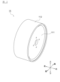
- FIG. 1 is a front view illustrating an example of an airless tire according to an embodiment of the present invention.
- FIG. 2 is a perspective view showing an example of the wheel shown in FIG. 1 .
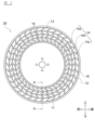
- FIG. 2 is a front view illustrating another example of an airless tire according to an embodiment of the present invention.
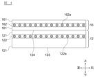
- FIG. 4 is a cross-sectional view of a main portion showing the outer ring and the tread taken along the line AA in FIG. 3.
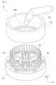
- FIG. 1 is a perspective view showing an example of an airless tire manufacturing apparatus according to an embodiment of the present invention.
- FIG. 6 is a plan view (part 1) showing a procedure for installing a wheel and a tread in the manufacturing apparatus shown in FIG. 5 .
- FIG. 1 is a front view illustrating an example of an airless tire according to an embodiment of the present invention.
- FIG. 2 is a perspective view showing an example of the wheel shown in FIG. 1 .
- FIG. 2 is a front view illustrating another example of an airless tire according to an embodiment of
- FIG. 6 is a plan view (part 2) showing the procedure for installing the wheel and the tread in the manufacturing apparatus shown in FIG. 5 .
- FIG. 6 is a plan view (part 3) showing the procedure for installing the wheel and the tread in the manufacturing apparatus shown in FIG. 5 .
- FIG. 2 is a perspective view showing another example of an airless tire manufacturing apparatus according to an embodiment of the present invention.
- FIG. 8 is a plan view (part 1) showing the procedure for handling the wheel, the tread, and the inner ring in the manufacturing apparatus shown in FIG. 7 .
- FIG. 8 is a plan view (part 2) showing the procedure for handling the wheel, the tread, and the inner ring in the manufacturing apparatus shown in FIG. 7 .
- FIG. 8 is a plan view (part 3) showing the procedure for handling the wheel, tread, and inner ring in the manufacturing apparatus shown in FIG. 7 .
- FIG. 2 is a front view illustrating an example of a spoke of the airless tire according to the embodiment of the present invention.
- FIG. 11 is a front view showing another example of a spoke of the airless tire according to the embodiment of the present invention.
- the side (outside) of a vehicle when an airless tire is mounted on the vehicle is defined as the front side.
- front rear
- upper lower
- lower right
- left respectively indicate the front, rear, upper, lower, right, and left of a vehicle on which an airless tire is mounted
- X-axis and Y-axis respectively indicate the horizontal and vertical directions when an airless tire manufacturing device (hereinafter also simply referred to as the manufacturing device) is viewed in a plane
- the Z-axis indicates the height direction relative to the installation position of the manufacturing device.
- the radial direction of the airless tire will be simply referred to as the radial direction
- the circumferential direction of the airless tire will be simply referred to as the circumferential direction.
- the radial direction of the airless tire is the same direction as the radial direction of the wheel and the inner ring
- the circumferential direction of the airless tire is the same direction as the circumferential direction of the wheel and the inner ring.
- FIG. 1 is a front view showing an example of an airless tire according to an embodiment of the present invention.
- An airless tire is a tire that supports a vehicle body by the reaction force of spokes made of an elastic material (hereinafter also referred to as an elastic material) rather than by air pressure.
- the airless tire of this embodiment can be applied to four-wheeled automobiles, two-wheeled automobiles, industrial vehicles, bicycles, and other vehicles, as well as carts.
- the airless tire 1 of this embodiment includes a wheel 11, a tread 12, spokes 13, and an intermediate ring 14.
- the wheel 11 is a member that is fixed to the vehicle hub (not shown) to connect with the vehicle, and is made of metal or other highly rigid materials. As shown in FIG. 2, the wheel 11 is made up of a disk 111 and a cylindrical rim 112. The disk 111 is shown in FIG. 1 as a circular member in the center of the airless tire 1, and the disk 111 is fixed to the vehicle hub to support the airless tire 1 on the axle. The shape of the wheel 11 can be set appropriately according to the required specifications of the airless tire 1.
- the disk 111 and the rim 112 may be molded as a single unit, or may be combined after being molded separately.
- the tread 12 is a cylindrical member having a tire width, and is disposed on the outermost periphery of the airless tire 1 to come into contact with the road surface.
- the tread 12 is made of a composite material in which an elastic material such as natural rubber or synthetic rubber is reinforced with metal or resin tire cords.
- a tread pattern is formed on the outer periphery of the tread 12, similar to that of conventional pneumatic tires, and forms the contact surface with the road surface.
- the inner diameter, outer diameter, thickness, and shape of the tread pattern of the tread 12 can be set as appropriate according to the required specifications of the airless tire 1.
- the spokes 13 are members that support the load (e.g., the vehicle weight) applied to the airless tire 1, and are plate-like members made of an elastic material such as elastic thermoplastic resin or elastic thermosetting resin, with a width equivalent to the tire width.
- the spokes 13 extend radially from the outer periphery of the wheel 11 (specifically, the outer periphery of the rim 112) toward the inner periphery of the tread 12, and are provided at equal intervals and spaced apart from each other along the circumferential direction of the airless tire 1.
- the spokes 13 are provided symmetrically with respect to the central axis of the airless tire 1. There is no particular limit to the number of spokes 13 provided on one airless tire 1, and can be set appropriately depending on the ground contact length of the airless tire 1, the load-bearing value of the spokes 13, vibration resistance, and other required specifications of the airless tire 1.
- the means for attaching the spokes 13 to the wheel 11 is not particularly limited as long as robustness can be ensured.
- a groove may be formed in the outer peripheral surface (hereinafter also referred to as the first outer peripheral surface) of the rim 112 that constitutes the wheel 11, and the inner peripheral end (hereinafter also referred to as the one end) of the spokes 13 may be fitted into this groove.
- the first outer peripheral surface and the one end may also be bonded with an adhesive, or may be connected with a bolt.
- the means for attaching the spokes 13 to the tread 12 is not particularly limited as long as robustness can be ensured.
- the inner peripheral surface (hereinafter also referred to as the first inner peripheral surface) of the tread 12 and the outer peripheral end (hereinafter also referred to as the other end) of the spokes 13 may be bonded with an adhesive, or may be connected with a bolt.
- the intermediate ring 14 is a member that transmits the deformation of the spokes 13 in the circumferential direction to the adjacent spokes 13 in order to support the load by the entire airless tire 1 when the spokes 13 are deformed by a radial load.
- the intermediate ring 14 is made of an elastic material such as an elastic thermoplastic resin or an elastic thermosetting resin, like the spokes 13.
- the intermediate ring 14 is formed in a cylindrical shape concentric with the wheel 11 and the tread 12, and is provided between the wheel 11 and the tread 12 to connect the multiple spokes 13 to each other.
- the means for attaching the intermediate ring 14 to the spokes 13 as long as robustness can be ensured.
- the intermediate ring 14 is bonded to the spokes 13 by an adhesive.
- the spokes 13 and the intermediate ring 14 may be integrally molded.
- the airless tire 1 shown in FIG. 1 has three intermediate rings 14a, 14b, and 14c, but the number of intermediate rings 14 provided in one airless tire 1 is not particularly limited.
- FIG. 3 is a front view showing another example of an airless tire according to an embodiment of the present invention.
- the airless tire 1a shown in FIG. 3 includes an inner ring 15 and an outer ring 16 in addition to a wheel 11, a tread 12, spokes 13, and an intermediate ring 14.
- the inner ring 15 is an annular member that connects one end of the multiple spokes 13, and is made of, for example, the same material as the spokes 13.
- the inner side of the inner ring 15 is bonded to the outer side of the wheel 11.
- a protrusion is provided on the inner surface of the inner ring 15 (hereinafter also referred to as the third inner surface) and the protrusion is fitted into a groove formed in the first outer surface to bond them.
- the third inner surface and the first outer surface may be bonded with an adhesive.
- the outer side of the inner ring 15 is also bonded to the spokes 13.
- one end of the spokes 13 is bonded to the outer surface of the inner ring 15 (hereinafter also referred to as the third outer surface) with an adhesive.
- the inner ring 15 may be molded integrally with the spokes 13.
- the outer ring 16 is an annular member that connects the other ends of the multiple spokes 13, and is made of, for example, the same material as the spokes 13.
- the outer side of the outer ring 16 is bonded to the inner side of the tread 12.
- the outer surface (hereinafter also referred to as the second outer surface) of the outer ring 16 and the first inner surface are bonded with an adhesive.
- the inner side of the outer ring 16 is bonded to the spokes 13.
- the other ends of the spokes 13 are bonded to the inner surface (hereinafter also referred to as the fourth inner surface) of the outer ring 16 with an adhesive.
- the outer ring 16 may be molded integrally with the spokes 13.
- the spokes 13, the inner ring 15, and the outer ring 16 may be molded integrally, or the spokes 13, the intermediate ring 14, the inner ring 15, and the outer ring 16 may be molded integrally.
- the contact area with the rim 112 is increased compared to when the spokes 13 are directly connected to the wheel 11, improving the load-bearing capacity of the airless tire 1a.
- the contact area with the tread 12 is increased compared to when the spokes 13 are directly connected to the tread 12, improving the load-bearing capacity of the airless tire 1a.
- the inner ring 15 and the outer ring 16 have a width equivalent to the tire width (for example, a width within a range of tire width ⁇ 5%) and an appropriate thickness according to the required specifications of the airless tire 1a.
- the spokes 13 extend radially from the third outer peripheral surface toward the first inner peripheral surface, connecting the inner ring 15 and the tread 12. If the airless tire has an outer peripheral ring 16, the spokes 13 extend radially from the first outer peripheral surface toward the fourth inner peripheral surface, connecting the wheel 11 and the outer peripheral ring 16. If the airless tire has an inner ring 15 and an outer peripheral ring 16 like the airless tire 1a shown in FIG. 3, the spokes 13 extend radially from the third outer peripheral surface toward the fourth inner peripheral surface, connecting the inner ring 15 and the outer peripheral ring 16.
- FIG. 4 is a cross-sectional view of the outer ring 16 and the tread 12 in the A-A cross section of FIG. 3, which is a cross section perpendicular to the circumferential direction of the airless tire 1a.
- the tread 12 shown in FIG. 4 is in contact with the road surface and has a first elastic portion 121 made of an elastic material and a first reinforcing layer 122 extending in the width direction of the tread 12 (left and right direction of the vehicle).
- the first reinforcing layer 122 includes tire cords 122a and hard rubber, and has a higher rigidity than the first elastic portion 121 made of an elastic material.
- the first reinforcing layer 122 is positioned closer to the first inner circumferential surface 124 than the contact surface 123 that is in contact with the road surface.
- the outer ring 16 shown in FIG. 4 has a second elastic portion 161 made of an elastic material, and a second reinforcing layer 162 extending in the width direction of the outer ring 16 (left and right direction of the vehicle).
- the second reinforcing layer 162 includes tire cords 162a and hard rubber, and has higher rigidity than the second elastic portion 161.
- the tread 12 of the airless tire 1 shown in FIG. 1 also has a first elastic portion 121 and a first reinforcing layer 122.
- intermediate ring 14, the inner ring 15, and the outer ring 16 are not essential components of the airless tire according to the embodiment of the present invention, and may be provided as needed or may be omitted.
- a wheel 11 and a tread 12 are prepared, and an airless tire is manufactured by combining the wheel 11 and the tread 12.
- the wheel 11 includes a plurality of spokes 13 that extend radially from a first outer peripheral surface to which one end is joined, and that are deformable in the radial direction, with the distance between the center of the wheel 11 and the other end being a predetermined distance longer than the radius of the first inner peripheral surface 124.
- the plurality of spokes 13 When combining the wheel 11 and the tread 12, the plurality of spokes 13 are deformed in the circumferential direction and/or radial direction so that the distance between the center of the wheel 11 and the other end is reduced (e.g., to be less than the radius of the first inner peripheral surface 124), and the tread 12 and the plurality of spokes 13 in the deformed state are arranged so that the first inner peripheral surface and the other end face each other, and the plurality of spokes 13 in the deformed state are returned to their pre-deformed state.
- Two embodiments of the manufacturing method of an airless tire are described below.
- FIG. 5 is a perspective view showing an example of a manufacturing apparatus according to an embodiment of the present invention.
- the manufacturing apparatus 2 shown in FIG. 5 is an apparatus for manufacturing an airless tire that does not have an inner ring 15 and in which the spokes 13 are directly joined to the wheel 11, like the airless tire 1 shown in FIG. 1.
- the manufacturing apparatus 2 includes a first base 21, a fixed member 22, a first movable member 23, a first pin 24, and conveying mechanisms 25 and 26.
- the first pedestal 21 is a member that supports the equipment that constitutes the manufacturing apparatus 2.
- the first pedestal 21 is installed, for example, on a level ground, and its position is fixed by anchor bolts or the like.
- the first pedestal 21 has an appropriate shape and rigidity within a range that allows it to adequately support the equipment that constitutes the manufacturing apparatus 2.
- the fixing member 22 is a member that fixes the wheel 11 to the first base 21, and is not particularly limited as long as it is capable of fixing the wheel 11 to the first base 21.
- the fixing member 22 shown in FIG. 5 has a base portion that is provided in the center of the first base 21 and is fixed to the first base 21 (or is part of the first base 21), and a pin that is inserted into a hole provided in the disc 111.
- the hole in the disc 111 is a hole through which a bolt is inserted when connecting the wheel 11 to the vehicle.
- the Z-axis direction is the width direction of the wheel 11.
- the first moving members 23 are members attached to the first base 21, and are movable in the radial direction of the wheel 11 fixed to the fixed member 22.
- six first moving members 23 are attached to the first base 21 shown in FIG. 5, and each of the six first moving members 23 moves independently in the radial direction on the XY plane perpendicular to the Z axis.
- the first moving members 23 include, for example, a worm gear (not shown) extending in the radial direction, and the first moving members 23 are moved in the radial direction by rotating this worm gear by a motor or the like.
- the first pin 24 is a pin fixed to the first moving member 23 along the circumferential direction, and as shown in FIG. 5, a plurality of first pins 24 are fixed to each first moving member 23. One end of the first pin 24 is fixed to the first moving member 23, and extends in the Z-axis direction (width direction of the wheel 11).
- the method of fixing the first pin 24 to the first moving member 23 is not particularly limited, and the first pin 24 may be fixed by a bolt or adhesive, or the first moving member 23 and the first pin 24 may be integrally molded.
- the first pin 24 is a pin that applies a first force to the spoke 13 in the radial direction (specifically, toward the center in the radial direction), and therefore has an appropriate shape and rigidity within a range in which the spoke 13 made of an elastic material can be deformed.
- the arrangement of the first pin 24 can be appropriately set within a range in which the spoke 13 can be appropriately deformed, and the shape of the first moving member 23 depends on the arrangement of the first pin 24. The first force will be described later.
- the transport mechanism 25 is a mechanism for transporting the tread 12, and is not particularly limited as long as it can properly position the tread 12 in the manufacturing apparatus 2.
- the transport mechanism 25 shown in FIG. 5 is a cylindrical member, and a support part 25a for supporting the tread 12 is provided at the lower end of the inner circumference side of the transport mechanism 25.
- the transport mechanism 25 is moved in the X-axis direction, the Y-axis direction, and the Z-axis direction by an arm (not shown) provided above the manufacturing apparatus 2, or the like.
- the transport mechanism 26 is a mechanism for transporting the wheel 11 and the inner ring 15, and removes the manufactured airless tire 1 from the manufacturing apparatus 2.
- the transport mechanism 26 is, for example, a robot arm as shown in FIG. 5, but is not particularly limited as long as it can properly handle the wheel 11, etc.
- step S1 When manufacturing the airless tire 1 shown in FIG. 1 using the manufacturing apparatus 2 shown in FIG. 5, first prepare the wheel 11 having a plurality of spokes 13 extending radially from a first outer peripheral surface to which one end is joined and deformable in the radial direction of the wheel 11, and the tread 12 (step S1).
- the wheel 11 having the spokes 13 is manufactured by integrally molding the spokes 13 and the intermediate ring 14 made of an elastic material (e.g., urethane resin such as thermoplastic polyurethane) using a molding method such as injection molding or vacuum casting, and joining one end of the spokes 13 to the first outer peripheral surface of the disk 111.
- an elastic material e.g., urethane resin such as thermoplastic polyurethane
- the method of joining the one end of the spokes 13 to the first outer peripheral surface is not particularly limited as long as robustness can be ensured.
- the wheel 11 may be inserted into a mold and integrally molded (insert molding) with the spokes 13 and the intermediate ring 14.
- the tread 12 is manufactured by, for example, wrapping the tire cord 122a corresponding to the first reinforcing layer 122 with raw rubber corresponding to the first elastic portion 121 to form a prepreg, and then heating and pressurizing the prepreg (vulcanizing it).
- the shapes of the spokes 13 and the intermediate ring 14 can be set appropriately within a range in which the spokes 13 can be deformed in the radial direction by the first pin 24.
- the diameter of the wheel 11 and the length of the spokes 13 are set so that the first distance from the center of the wheel 11 to the other ends of the multiple spokes 13 is a first predetermined distance longer than the radius of the first inner circumferential surface.
- the first distance D1 from the center C1 of the wheel to the other ends E1 of the spokes 13 is set to be a first predetermined distance longer than the radius B of the first inner circumferential surface 124 shown in FIG. 6B.
- the first predetermined distance can be set appropriately within a range in which the other ends E1 of the spokes 13 can be pressed against the first inner circumferential surface 124 and the spokes 13 can be fixed to the tread 12, and is, for example, 5 to 10% of the radius B of the first inner circumferential surface 124.
- the wheel 11 having a plurality of spokes 13 is transported by a transport mechanism 26 shown by dashed lines in Fig. 6A, and the pins of the fixing member 22 are inserted into the holes in the disk 111 to fix the wheel 11 to the fixing member 22 (step S2).
- the first pins 24 are disposed between adjacent spokes 13, so that when the wheel 11 is fixed to the fixing member 22, the first pins 24 are inserted between adjacent spokes 13 as shown in Fig. 6A.
- the number of first pins 24 does not necessarily need to be the same as the number of spokes 13, and for example, the first pins 24 may be disposed every other spoke 13 between adjacent spokes 13.
- a first radial force is applied to the multiple spokes 13 so that the first distance D1 shown in FIG. 6A is less than the radius B of the first inner circumferential surface 124 shown in FIG. 6B (step S3).
- the first moving member 23 is moved radially toward the center C1 (in the direction of the arrow shown in FIG. 6A), and a first force is applied to the multiple spokes 13 via the intermediate ring 14c in contact with the first pin 24 so that the first distance D1 is less than the radius B of the first inner circumferential surface 124 for all spokes 13.
- the first force is applied to the spokes 13 by applying a second radial force to the intermediate ring 14c.
- the spokes 13 are deformed and the radial length is shortened (diameter is reduced), and as shown in FIG. 6B, the first distance D1 is shorter than the radius B of the first inner circumferential surface 124.
- a pin is used to apply the first force, but the means for applying force to the spokes 13 is not limited to a pin.
- the spokes 13 may be held by a clamp or the like, and the clamp holding the spokes 13 may be moved in the radial direction.
- the radial length of the spokes 13 to which the first force is applied may be different for each spoke 13.
- the direction of the arrow shown in FIG. 6A is also referred to as the first direction.
- the spokes 13 may have multiple bends between one end and the other end that bend in the direction connecting the one end and the other end.
- the spokes 13 shown in FIG. 6A have bends 131, 132, and 133 between one end and the other end that deform in the circumferential direction.
- the intermediate ring 14 may also connect the bends of the spokes 13 to each other.
- the intermediate ring 14a shown in FIG. 6A connects the bend 131 to bends 131a and 131b of adjacent spokes 13.
- the diameter of the spokes 13 can be reduced with a smaller force.
- the airless tire 1 includes an intermediate ring 14, the circumferential and radial deformations of the spokes 13 are transmitted to adjacent spokes 13 by the intermediate ring 14. Therefore, when applying a second force to the intermediate ring 14 to make the first distance D1 less than the radius B of the first inner circumferential surface 124, the second force may be applied to only a portion of the intermediate ring 14. For example, every other first pin 24 shown in FIG. 5 is thinned out so that every other first pin 24 is disposed between adjacent spokes 13. This makes it possible to prevent the spokes 13 from being narrowed more than necessary.
- FIG. 9A is a front view showing an example of a spoke 13 of an airless tire according to an embodiment of the present invention.
- the wheel 11 shown in FIG. 9A includes a plurality of spokes 13 and an outer circumferential ring 16, and the tread 12 is joined to the outer circumferential ring 16.
- the spoke 13 shown in FIG. 9A has a first protrusion P1, and the first pin 24 is in contact with the first protrusion P1. As shown in FIG.
- the radial direction A1 and the direction A2 connecting one end of the spoke 13 to the other end form a minor angle ⁇ within a predetermined range.
- the first force is applied to the first protrusion P1.
- the shape of the first protrusion P1 and the predetermined range of the minor angle ⁇ can be appropriately set within a range in which the first force can be appropriately applied to the first protrusion P1, and the predetermined range is, for example, 10 to 30°.
- the tread 12 is transported using the transport mechanism 25 shown by the dashed line in Fig. 6B, and the tread 12 and the wheel 11 with the first force applied to the spokes 13 are positioned so that the first inner circumferential surface 124 faces the other end E1 (step S4).
- the transport mechanism 25 with the tread 12 supported on the support portion 25a is moved from above to below the manufacturing device 2 along the Z-axis direction, and the tread 12 is positioned outside the spokes 13 with the first force applied so that the first inner circumferential surface 124 faces the other end E1.
- the transport mechanism 26 moves to a position that does not impede the movement of the transport mechanism 25.
- step S5 With the wheel 11 and tread 12 positioned such that the first inner circumferential surface 124 and the other end E1 face each other, the first force applied to the spokes 13 is removed, and the other end E1 of the spokes 13 is pressed against the first inner circumferential surface 124 to make intimate contact, and the spokes 13 are fixed to the tread 12 (step S5).
- the first moving member 23 is moved radially toward the first inner circumferential surface 124 (in the direction of the arrow shown in FIG. 6B), and the first force is removed from the spokes 13.
- the first distance D1 is longer than the radius B of the first inner circumferential surface 124, so that the other end E1 of the spokes 13 is pressed against the first inner circumferential surface 124 and fixed to the first inner circumferential surface 124.
- the other end E1 of the spoke 13 is pressed against the first inner circumferential surface 124, causing circumferential tensile stress in the tire cord 122a of the tread 12.
- the first direction of the arrow shown in FIG. 6A and the direction of the arrow shown in FIG. 6B are opposite to each other.
- step S6 The airless tire 1 manufactured by combining the wheel 11 and the tread 12 is removed from the manufacturing apparatus 2 using the conveying mechanism 26 (step S6).
- the removed airless tire 1 is conveyed to the next step.
- the conveying mechanism 26 then conveys a new wheel (step S7). Steps S2 to S7 are repeated until the desired number of airless tires 1 have been manufactured. Furthermore, if the wheel 11 and tread 12 are required, step S1 is executed as necessary.
- the wheel 11 may have, in addition to the multiple spokes 13, an outer ring 16 having a second outer surface with a second diameter that is longer than the first diameter of the first inner surface 124 by a first predetermined length.
- the first predetermined length can be set to an appropriate value within the range in which the second outer surface can be pressed against the first inner surface 124 and the outer ring 16 can be fixed to the tread 12, and is, for example, 2.5 to 5% of the first diameter of the first inner surface 124.
- the first predetermined length is also simply referred to as the predetermined length.
- step S3a the manufacturing device 2 applies a first force to the spokes 13 so that the maximum value of the diameter of the second outer surface is less than the first diameter. Then, the tread 12 and the wheel 11 with the first force applied to the spokes 13 are arranged so that the first inner surface 124 and the second outer surface face each other (step S4a), the first force applied to the spokes 13 is removed, and the second outer surface is pressed against the first inner surface 124 to be in close contact (step S5a).
- step S1 the wheel 11 including the spokes 13 and the outer ring 16 is prepared, and steps S3 to S5 are replaced by steps S3a to S5a.
- step S3a it is not necessary for the diameter of the second outer surface to be uniformly reduced, and it is sufficient that the maximum value of the diameter of the second outer surface is less than the first diameter.
- the wheel 11 having the spokes 13 and the outer ring 16 is fixed to the fixed member 22 by the transport mechanism 26, the first moving member 23 is moved in a first direction on the XY plane, and a second force is applied to the intermediate ring 14c in contact with the first pin 24 so that the maximum value of the diameter of the second outer peripheral surface is less than the first diameter.
- the transport mechanism 25 with the tread 12 supported on the support portion 25a is moved from above to below the manufacturing device 2 along the Z axis direction, and the tread 12 is positioned outside the multiple spokes 13 to which the first force is applied so that the first inner peripheral surface 124 and the second outer peripheral surface face each other, and the first moving member 23 is moved in a direction opposite to the first direction on the XY plane to remove the first force from the spokes 13.
- the manufacturing device 2 is used to replace the tread 12 of the airless tire 1 with another tread.
- the conveying mechanism 25 moved downward in the Z-axis direction as shown in FIG. 6B
- the wheel 11 of the airless tire 1 is fixed to the fixed member 22 by the conveying mechanism 26.
- the first moving member 23 is moved in the first direction to apply a second force to the intermediate ring 14c so that the first distance D1 is less than the radius B of the first inner circumferential surface 124, and the multiple spokes 13 fixed to the tread 12 are separated from the tread 12.
- the tread 12 separated from the multiple spokes 13 is conveyed to the next process (e.g., a regeneration process) by the conveying mechanism 25.
- a tread different from the separated tread 12 is placed on the support portion 25a of the transport mechanism 25, and the transport mechanism 25 is moved to place the other tread and the wheel 11 with the first force applied to the multiple spokes 13 (the second force applied to the intermediate ring 14c) so that the inner circumferential surface of the other tread (hereinafter also referred to as the second inner circumferential surface) faces the other end E1.
- the first moving member 23 is moved in the direction opposite to the first direction to remove the first force applied to the multiple spokes 13, and the multiple spokes 13 are fixed to the other tread.
- the airless tire 1 with the replaced tread 12 is removed from the manufacturing apparatus 2 by the transport mechanism 26.
- the wheel 11 When the wheel 11 has an outer ring 16 and the tread 12 of the airless tire 1 is replaced with another tread using the manufacturing device 2, the wheel 11 is fixed to the fixing member 22, and then the first moving member 23 is moved in the first direction to apply a second force to the intermediate ring 14c so that the maximum value of the diameter of the second outer peripheral surface is less than the first diameter, and the multiple spokes 13 fixed to the tread 12 are separated from the tread 12.
- Second Embodiment Fig. 7 is a perspective view showing another example of a manufacturing apparatus according to an embodiment of the present invention.
- the manufacturing apparatus 3 shown in Fig. 7 is an apparatus for manufacturing an airless tire having an inner circumferential ring 15 and in which the spokes 13 are not directly joined to the wheel 11, like the airless tire 1a shown in Fig. 3.
- the manufacturing apparatus 3 includes a second base 31, a second moving member 32, a third moving member 33, a second pin 34, a third pin 35, and transport mechanisms 36 and 37.
- the second base 31 is a member that supports the equipment that constitutes the manufacturing apparatus 3, and is fixed in position in the same manner as the first base 21.
- the second base 31 has an appropriate shape and rigidity within a range that allows it to adequately support the equipment that constitutes the manufacturing apparatus 3.
- the second moving member 32 and the third moving member 33 are members attached to the second base 31 and are movable in the radial direction relative to the second base 31.
- the second moving member 32 and the third moving member 33 shown in FIG. 7 move in the radial direction on the XY plane perpendicular to the Z axis.
- the mechanism by which the second moving member 32 and the third moving member 33 move is the same as that of the first moving member 23.
- the third moving member 33 is positioned outward of the second moving member 32.
- the second pin 34 is a pin fixed to the second moving member 32 along the circumferential direction, and as shown in FIG. 7, a plurality of second pins 34 are fixed to the second moving member 32. One end of the second pin 34 is fixed to the second moving member 32 and extends in the Z-axis direction. There is no particular limitation on the method of fixing the second pin 34.
- the second moving member 32 and the second pin 34 may be integrally molded.
- the third pin 35 is a pin fixed to the third moving member 33 along the circumferential direction, and as shown in FIG. 7, a plurality of third pins 35 are fixed to the third moving member 33. One end of the third pin 35 is fixed to the third moving member 33 and extends in the Z-axis direction. There is no particular limitation on the method of fixing the third pin 35.
- the third moving member 33 and the third pin 35 may be integrally molded.
- the second pin 34 and the third pin 35 are pins that apply the third and fourth radial forces to the spoke 13, respectively, and therefore have an appropriate shape and rigidity within a range in which the spoke 13, which is made of an elastic material, can be deformed.
- the arrangement of the second pin 34 and the third pin 35 can be appropriately set within a range in which the spoke 13 can be appropriately deformed, and the radial distance between the second pin 34 and the third pin 35 can be appropriately set within a range in which the spoke 13 can be appropriately deformed.
- the shapes of the second moving member 32 and the third moving member 33 depend on the arrangement of the second pin 34 and the third pin 35, respectively. The third force and the fourth force will be described later.
- the transport mechanism 36 is a mechanism for transporting the tread 12 and has a support portion 36a that supports the tread 12.
- the transport mechanism 37 is a mechanism for transporting the wheel 11 and the inner ring 15.
- step S11 When manufacturing an airless tire in which one ends of the multiple spokes 13 shown in FIG. 1 are connected by an inner ring 15 using the manufacturing device 3 shown in FIG. 7, first prepare the wheel 11, the tread 12, and the inner ring 15 having a third outer peripheral surface to which one ends of the multiple spokes 13 are connected (step S11).
- step S11 When the manufacturing device 3 is used to join the tread 12 and the inner ring 15, and the wheel 11 and the inner ring 15 are joined separately, the tread 12 and the inner ring 15 having a third outer peripheral surface are prepared in step S11.
- the inner ring 15 has multiple spokes 13 that extend radially from the third outer peripheral surface to which one ends are joined and are deformable in the radial direction of the inner ring 15.
- the diameter (inner diameter) of the inner ring 15 is set to be shorter than the diameter (outer diameter) of the wheel 11 by a second predetermined length.
- the second predetermined length can be set to an appropriate value within a range in which the third inner peripheral surface can be appropriately joined to the first outer peripheral surface, for example, 1 to 5% of the diameter of the wheel 11.
- the inner peripheral ring 15 is molded integrally with the spokes 13 and the intermediate ring 14, which are made of an elastic material, using a molding method such as injection molding or vacuum casting.
- the manufacturing method of the tread 12 is the same as in the first embodiment, so a description thereof will be omitted.
- the shapes of the spokes 13 and the intermediate ring 14 can be set appropriately within a range in which the spokes 13 can be deformed in the radial direction by the second pin 34 and the third pin 35.
- the outer diameter of the inner ring 15 (i.e., the diameter of the third outer surface) and the length of the spokes 13 are set so that the second distance from the center of the inner ring 15 to the other ends of the multiple spokes 13 is longer than the radius B of the first inner surface 124 by a second predetermined distance.
- the second distance D2 from the center C2 of the inner ring 15 to the other ends E2 of the spokes 13 is set to be longer than the radius B of the first inner surface 124 by a second predetermined distance as shown in FIG. 8B.
- the second predetermined distance can be set appropriately within a range in which the spokes 13 can be fixed to the tread 12, similar to the first predetermined distance, and is, for example, 5 to 10% of the radius B of the first inner surface 124.
- the inner ring 15 having a plurality of spokes 13 is transported by a transport mechanism 37 shown by a dashed line in FIG. 8A, and the second pin 34 and the third pin 35 are inserted between adjacent spokes 13 (step S12).
- the Z-axis direction is the width direction of the airless tire.
- the second pin 34 and the third pin 35 are arranged so as to be inserted between adjacent spokes 13. Note that the second pins 34 and the third pins 35 do not necessarily need to be arranged in the same number as the number of spokes 13, and for example, the second pins 34 and the third pins 35 may be arranged every other one between adjacent spokes 13.
- a third radial force and a fourth force in the opposite direction to the third force are applied to the multiple spokes 13 so that the second distance D2 shown in FIG. 8A is less than the radius B of the first inner surface 124 shown in FIG. 8B (step S13).
- the second moving member 32 is moved radially (in the direction of the arrow shown on the inner side of FIG. 8A) toward the outer periphery (other end E2), and the third force is applied to the spokes 13 via the intermediate ring 14a in contact with the second pin 34.
- the third force is applied to the spokes 13 by applying a fifth radial force to the intermediate ring 14a (first intermediate ring).
- the third moving member 33 is moved radially (in the direction of the arrow shown on the outer periphery of FIG. 8A) toward the center C2, and the fourth force is applied to the spokes 13 via the intermediate ring 14c in contact with the third pin 35.
- a sixth force in the opposite direction to the fifth force is applied to the intermediate ring 14c (second intermediate ring) that is closer to the other end E2 than the intermediate ring 14a (first intermediate ring), thereby applying a fourth force to the spoke 13.
- the spoke 13 is deformed and the radial length is shortened (diameter is reduced), and as shown in FIG. 8B, the second distance D2 becomes shorter than the radius B of the first inner circumferential surface 124.
- the third force is applied to the spokes 13 via the intermediate ring 14a, but the second pin 34 may be arranged inside the inner ring 15 (so that the second pin 34 and the third inner surface face each other) and the third force may be applied to the spokes 13 via the inner ring 15.
- a pin is used to apply the third and fourth forces, but the means for applying the forces to the spokes 13 is not limited to pins.
- the ends of the spokes 13 may be held by clamps or the like, and the clamps holding the ends of the spokes 13 may be moved so that they approach each other.
- the radial length of the spokes 13 to which the third and fourth forces are applied may be different for each spoke 13.
- the second pin 34 and the third pin 35 may move in opposite directions relative to each other to apply the third and fourth forces to one spoke 13, and one of the second pin 34 and the third pin 35 may move in the radial direction and the other may be stationary.
- the direction of the arrow shown on the inner circumference side of FIG. 8A is also referred to as the second direction, and the direction of the arrow shown on the outer circumference side of FIG. 8A is also referred to as the third direction.
- the spokes 13 may have multiple bent portions between one end and the other end that bend in the direction connecting the one end and the other end.
- the spokes 13 shown in FIG. 8A have three bent portions that deform in the circumferential direction between one end and the other end, similar to the spokes 13 shown in FIG. 6A.
- the intermediate ring 14 may also connect the bent portions of the spokes 13 to each other.
- the intermediate ring 14a shown in FIG. 8A connects the bent portions of adjacent spokes 13 to each other, similar to the intermediate ring 14a shown in FIG. 6A.
- FIG. 8A by applying a third force and a fourth force to the intermediate ring 14 that connects the bent portions of the spokes 13 to each other, the diameter of the spokes 13 can be reduced with a smaller force.
- the airless tire includes an intermediate ring 14, the circumferential and radial deformations of the spokes 13 are transmitted to adjacent spokes 13 by the intermediate ring 14, and therefore when the third and fourth forces are applied to the intermediate ring 14 to make the second distance D2 less than the radius B of the first inner circumferential surface 124, the third and fourth forces may be applied only to a portion of the intermediate ring 14. For example, every other second pin 34 and third pin 35 shown in FIG. 7 are thinned out so that the second pin 34 and third pin 35 are arranged every other one between adjacent spokes 13. This makes it possible to prevent the spokes 13 from being narrowed more than necessary.
- Fig. 9B is a front view showing another example of the spoke 13 of the airless tire according to the embodiment of the present invention.
- the inner ring 15 shown in Fig. 9B has a plurality of spokes 13 and an outer ring 16, and the tread 12 is joined to the outer ring 16.
- the radial direction A1 and the direction A2 connecting one end of the spoke 13 to the other end form a minor angle ⁇ within a predetermined range.
- the third force is applied to the second protrusion P2, and the fourth force is applied to the third protrusion P3.
- the shapes of the second protrusion P2 and the third protrusion P3 and the specified range of the minor angle ⁇ can be set appropriately within a range in which the third force and the fourth force can be appropriately applied to the second protrusion P2 and the third protrusion P3, respectively, and the specified range is, for example, 10 to 30°.
- step S14-1 the tread 12 is transported using the transport mechanism 36 shown by the dashed lines, and the tread 12 and the inner ring 15 with the third and fourth forces applied to the spokes 13 are arranged so that the first inner surface 124 faces the other end E2 (step S14-1). Furthermore, the wheel 11 is transported using the transport mechanism 37 shown by the dashed lines in FIG. 8B, and the wheel 11 and the inner ring 15 with the third and fourth forces applied to the spokes 13 are arranged so that the first outer surface of the wheel 11 faces the third inner surface of the inner ring 15 (step S14-2). If the tread 12 and the inner ring 15 are joined using the manufacturing device 3 and the wheel 11 and the inner ring 15 are joined separately, step S14-2 is not performed and the wheel 11 is not arranged.
- the conveying mechanism 36 with the tread 12 supported on the support portion 36a is moved from above to below the manufacturing device 3 along the Z-axis direction, and the tread 12 is arranged on the outside of the spokes 13 so that the first inner circumferential surface 124 faces the other end E2.
- the wheel 11 is gripped by the conveying mechanism 37, and the wheel 11 is arranged on the inside of the inner ring 15 so that the first outer circumferential surface faces the third inner circumferential surface.
- the manufacturing device 3 may have a fixing member for fixing the wheel 11, as in the manufacturing device 2, and the wheel 11 gripped by the conveying mechanism 37 may be fixed to the second pedestal 31 by the fixing member.
- step S15 With the wheel 11, tread 12 and inner ring 15 positioned so that the first outer surface faces the third inner surface and the other end E2 faces the first inner surface 124, the third and fourth forces applied to the spokes 13 are removed and the other ends E2 of the spokes 13 are pressed against the first inner surface 124 to adhere to it, and the spokes 13 are fixed to the tread 12 (step S15). If the tread 12 and inner ring 15 are joined using the manufacturing device 3 and the wheel 11 and inner ring 15 are joined separately, in step S15, with the tread 12 and inner ring 15 positioned so that the other ends E2 faces the first inner surface 124, the third and fourth forces applied to the spokes 13 are removed.
- the second moving member 32 is moved radially toward the center C2 (in the direction of the arrow shown on the inner peripheral side of Fig. 8B) to remove the third force from the spokes 13, and the third moving member 33 is moved radially toward the outer peripheral side (the other end E2) (in the direction of the arrow shown on the outer peripheral side of Fig. 8B) to remove the fourth force from the spokes 13.
- the second moving member 32 is moved radially toward the center C2 (in the direction of the arrow shown on the inner peripheral side of Fig. 8B) to remove the third force from the spokes 13
- the third moving member 33 is moved radially toward the outer peripheral side (the other end E2) (in the direction of the arrow shown on the outer peripheral side of Fig. 8B) to remove the fourth force from the spokes 13.
- the second moving member 32 is moved radially toward the center C2 (in the direction of the arrow shown on the inner peripheral side of Fig. 8B) to remove the third force from the spokes 13
- the second distance D2 is longer than the radius B of the first inner peripheral surface 124, so that the other end E2 of the spoke 13 is pressed against the first inner peripheral surface 124 and fixed to the first inner peripheral surface 124.
- the other end E2 of the spoke 13 is pressed against the first inner circumferential surface 124, generating circumferential tensile stress in the tire cord 122a of the tread 12.
- step S16 The airless tire manufactured by combining the wheel 11, tread 12, and inner ring 15 is removed from the manufacturing apparatus 3 using the transport mechanism 37 (step S16). If only the tread 12 and inner ring 15 are combined, the combined parts are removed from the manufacturing apparatus 3 using the transport mechanism 36. The removed airless tire is transported to the next process. The transport mechanism 37 then transports a new inner ring 15 (step S17). Steps S12 to S17 are repeated until the desired number of airless tires have been manufactured. Furthermore, if the wheel 11, tread 12, and inner ring 15 are required, step S11 is executed as necessary.
- the inner ring 15 may include an outer ring 16 having a second outer peripheral surface with a second diameter that is longer than the first diameter of the first inner peripheral surface 124 by a first predetermined length.
- the manufacturing device 3 applies a third force and a fourth force to the multiple spokes 13 so that the maximum value of the diameter of the second outer peripheral surface is less than the first diameter (step S13a).
- step S14-1a the tread 12 and the inner ring 15 with the third force and the fourth force applied to the multiple spokes 13 are arranged so that the first inner peripheral surface 124 and the second outer peripheral surface face each other
- step S14-2a the wheel 11 and the inner ring 15 with the third force and the fourth force applied to the multiple spokes 13 are arranged so that the first outer peripheral surface and the third inner peripheral surface face each other
- step S15a the third and fourth forces applied to the spokes 13 are removed, and the second outer peripheral surface is pressed against the first inner peripheral surface 124 to make it adhere closely.
- step S11 if the inner peripheral ring 15 includes the outer peripheral ring 16, in step S11, the inner peripheral ring 15 including the spokes 13 and the outer peripheral ring 16 is prepared, and steps S13 to S15 are replaced with steps S13a to S15a.
- step S13a it is not necessary for the diameter of the second outer peripheral surface to be uniformly reduced, and it is sufficient that the maximum value of the diameter of the second outer peripheral surface is less than the first diameter.
- step S14-2a is not performed and the wheel 11 is not placed.
- the conveying mechanism 37 is used to convey the spokes 13 and the inner ring 15 including the outer ring 16, and the second pin 34 and the third pin 35 are inserted between the adjacent spokes 13.
- the second moving member 32 is moved in the second direction on the XY plane
- the third moving member 33 is moved in the third direction on the XY plane, and a fifth force is applied to the intermediate ring 14a in contact with the second pin 34, and a sixth force is applied to the intermediate ring 14c in contact with the third pin 35, so that the maximum value of the diameter of the second outer peripheral surface is less than the first diameter.
- the manufacturing device 3 is used to replace the tread 12 of the airless tire with another tread.
- the conveying mechanism 36 moved downward in the Z-axis direction as shown in FIG. 8B
- the wheel 11 of the airless tire is placed at the center of the conveying mechanism 36 by the conveying mechanism 37.
- the third moving member 33 is moved in the third direction to apply a third force and a fourth force to the multiple spokes 13 fixed to the tread 12 so that the second distance D2 is less than the radius B of the first inner circumferential surface 124, and the multiple spokes 13 are separated from the tread 12.
- a tread different from the separated tread 12 is placed on the support portion 25a of the transport mechanism 36, and the transport mechanisms 36, 37 are moved to place the other tread and the inner ring 15 with the third and fourth forces applied to the multiple spokes 13 so that the second inner surface faces the other end E2. Then, the third moving member 33 is moved in the second direction to remove the third and fourth forces applied to the multiple spokes 13, and the multiple spokes 13 are fixed to the other tread.
- the airless tire with the replaced tread 12 is removed from the manufacturing device 3 by the transport mechanism 37.
- the inner ring 15 includes the outer ring 16
- the tread 12 of the airless tire 1 is replaced with another tread using the manufacturing device 2
- the inner ring 15 is inserted through the second pin 34 and the third pin 35, and then the second moving member 32 is moved in the second direction to apply a third force to the intermediate ring 14a and the third moving member 33 is moved in the third direction to apply a fourth force to the intermediate ring 14c so that the maximum value of the diameter of the second outer peripheral surface is less than the first diameter, and the multiple spokes 13 fixed to the tread 12 are separated from the tread 12.
- a wheel 11 having a first outer circumferential surface and coupled to a vehicle, and a tread 12 having a first inner circumferential surface 124 and contacting a road surface are prepared, and the wheel 11 includes a plurality of spokes 13 having one end which is an end on the inner circumferential side and the other end which is an end on the outer circumferential side.
- a first distance D1 from a center C1 of the wheel 11 to the other ends E1 of the spokes 13 is longer than a radius B of the first inner circumferential surface 124 by a first predetermined distance, a first force is applied to the spokes 13 toward the center in the radial direction so that the first distance D1 is reduced, the tread 12 and the wheel 11 in a state in which the first force is applied to the spokes 13 are arranged such that the first inner circumferential surface 124 and the other ends E2 face each other, and the first force applied to the spokes 13 is removed.
- the wheel 11 is prepared, which includes the plurality of spokes 13 and an outer peripheral ring 16 that has a second outer peripheral surface with a second diameter that is a predetermined length longer than the first diameter of the first inner peripheral surface 124 and connects the other end E1, and the first force is applied to the plurality of spokes 13 so that the maximum value of the diameter of the second outer peripheral surface is less than the first diameter, and the tread 12 and the wheel 11 with the first force applied to the plurality of spokes 13 are arranged so that the first inner peripheral surface 124 and the second outer peripheral surface face each other.
- This increases the bonding area with the tread 12, improving the load-bearing capacity of the airless tire.
- the first force is applied to the multiple spokes 13 fixed to the tread 12 so that the first distance D1 is less than the radius B, and the multiple spokes 13 are separated from the tread 12, and another tread different from the tread 12 and the wheel 11 with the first force applied to the multiple spokes 13 are arranged so that the second inner circumferential surface of the other tread faces the other end E1, and the first force applied to the multiple spokes 13 is removed to fix the multiple spokes 13 to the other tread.
- the spoke 13 has a first protrusion P1, and the direction A1 connecting the one end and the other end E1 of the spoke 13 forms a minor angle within a predetermined range with the radial direction A2, and when the first force is applied to the spoke 13, the first force is applied to the first protrusion P1. This makes it possible to apply the first force to the spoke 13 without providing an intermediate ring 14.
- the spokes 13 have multiple bends between the one end and the other end E1, and the bends are bent in the direction connecting the one end and the other end E1
- the airless tire includes an intermediate ring 14 that connects the bends of adjacent spokes, and the first force is applied to the spokes 13 by applying the second radial force to the intermediate ring 14. This makes it possible to reduce the first force required to deform the spokes 13.
- a first base 21 having a fixed position, a fixed member 22 provided on the first base 21 and fixing the wheel 11 to the first base 21, a first movable member 23 attached to the first base 21 so as to be movable in the radial direction, a plurality of first pins 24 extending in the width direction of the wheel 11 and fixed to the first movable member 23 along the circumferential direction of the wheel 11, the tread 12, and a device for transporting the tread 12 when positioning the wheel 11 in a state in which the first force is applied to the plurality of spokes 13 are arranged.
- the manufacturing device 2 includes conveying mechanisms 25 and 26 for conveying the wheel 11 to the fixed member 22, the first pin 24 is inserted between the adjacent spokes 13, the first moving member 23 is moved in a first direction to apply the first force to the multiple spokes 13 so that the first distance D1 is less than the radius B, the tread 12 is positioned outside the multiple spokes 13 to which the first force is applied so that the first inner circumferential surface 124 faces the other end E1, and the first moving member 23 is moved in a direction opposite to the first direction to remove the first force.
- a tread 12 having a first inner circumferential surface 124 and contacting the road surface, and an inner circumferential ring 15 having a third outer circumferential surface to which one end of the inner circumferential side of a plurality of spokes 13 is connected are prepared, the inner circumferential ring 15 has a plurality of spokes 13 that extend radially from the third outer circumferential surface to which the one end is joined and that are deformable in the radial direction of the inner circumferential ring 15, and a second distance D2 from a center C2 of the inner circumferential ring 15 to the other end E2 of the outer circumferential side of the plurality of spokes 13 is determined by the distance D2 from the first inner circumferential surface 124 to the other end E2 of the outer circumferential side of the plurality of spokes 13.
- a method for manufacturing an airless tire which applies a third radial force and a fourth force in a direction opposite to the third force to the spokes 13 so that the second distance D2 is reduced by a second predetermined distance longer than the radius B of the circumferential surface 124, and arranges the tread 12 and the inner ring 15 with the third and fourth forces applied to the spokes 13 so that the other end E2 faces the first inner circumferential surface 124, and removes the third and fourth forces applied to the spokes 13. This makes it possible to manufacture an airless tire that suppresses excessive deformation of the spokes 13.
- the third force and the fourth force are applied to the multiple spokes 13 fixed to the tread 12 so that the second distance D2 is less than the radius B, and the multiple spokes 13 are separated from the tread 12, and another tread different from the tread 12 and the inner ring 15 in a state in which the third force and the fourth force are applied to the multiple spokes 13 are arranged so that the second inner surface of the other tread faces the other end E2, and the third force and the fourth force applied to the multiple spokes 13 are removed to fix the multiple spokes 13 to the other tread.
- the spoke 13 has a second protrusion P2 and a third protrusion P3 located closer to the other end E2 than the second protrusion P2, and the direction A2 connecting the one end and the other end E2 of the spoke 13 forms a minor angle with the radial direction A1 within a predetermined range, and the third force is applied to the second protrusion P2 and the fourth force is applied to the third protrusion P3.
- the spokes 13 have multiple bends between the one end and the other end E2, and the bends are bent in the direction connecting the one end and the other end E2, and the airless tire includes multiple intermediate rings 14 that connect the bends of adjacent spokes 13, and applies the fifth force in the radial direction to a first intermediate ring and applies a sixth force in the opposite direction to the fifth force to a second intermediate ring that is closer to the other end than the first intermediate ring, thereby applying the third force and the fourth force to the multiple spokes 13. This makes it possible to reduce the first force required to deform the spokes 13.
- a manufacturing device 3 that includes a second base 31 whose position is fixed, a second movable member 32 that is attached so as to be movable in the radial direction relative to the second base 31, a third movable member 33 that is attached so as to be movable in the radial direction relative to the second base 31 and that is disposed outside the second movable member 32, a plurality of second pins 34 that extend in the width direction of the inner ring 15 and are fixed to the second movable member 32 along the circumferential direction of the inner ring 15, a plurality of third pins 35 that extend in the width direction of the inner ring 15 and are fixed to the third movable member 33 along the circumferential direction, a wheel 11 that is connected to a vehicle, the tread 12, and transport mechanisms 36, 37 that transport the wheel 11 and the tread 12 when arranging the inner ring 15 in a state in which the third force and the fourth force are applied to the plurality of spokes 13, and the manufacturing device
- the second pin 34 and the third pin 35 are inserted between the spokes 13, and the second moving member 32 is moved in the second direction to apply the third force to the plurality of spokes 13 and the third moving member 33 is moved in a third direction opposite to the second direction to apply the fourth force to the plurality of spokes 13 so that the second distance D2 is less than the radius B.
- the wheel 11 is disposed inside the inner ring 15 in a state in which the third force and the fourth force are applied to the plurality of spokes 13 so that the first outer surface of the wheel 11 and the third inner surface of the inner ring 15 face each other, and the tread 12 is disposed outside the plurality of spokes 13 in a state in which the third force and the fourth force are applied so that the other end E2 and the first inner surface 124 face each other, and the second moving member 32 is moved in the third direction and the third moving member 33 is moved in the second direction to remove the third force and the fourth force.
- This makes it possible to manufacture an airless tire that suppresses excessive deformation of the spokes 13.
- the tread 12 has a first elastic portion 121 made of an elastic material, and a first reinforcing layer 122 that extends in the width direction of the tread 12 and has a higher rigidity than the first elastic portion 121, and the first reinforcing layer 122 is disposed at a position closer to the first inner circumferential surface 124 than a contact surface 123 that contacts the road surface. This makes it possible to further suppress excessive deformation of the spokes 13.
- the outer ring 16 has a second elastic portion 161 made of an elastic material, and a second reinforcing layer 162 that extends in the width direction of the outer ring 16 and has a higher rigidity than the second elastic portion 161. This makes it possible to further suppress excessive deformation of the spokes 13.
- an airless tire manufacturing device having a plurality of spokes 13, each having one end which is an inner circumferential end and the other end which is an outer circumferential end, extending radially from a first outer circumferential surface of a wheel 11 which is connected to a vehicle toward a first inner circumferential surface 124 of a tread 12 which comes into contact with a road surface and which is deformable in the radial direction of the wheel 11, with the one ends of the plurality of spokes 13 being joined to the first outer circumferential surface
- the device comprising: a first base 21 having a fixed position; a fixing member 22 provided on the first base 21 and fixing the wheel 11 to the first base 21; a first movable member 23 attached to the first base 21 so as to be movable in the radial direction relative to the first base 21; a plurality of first pins 24 extending in the width direction of the wheel 11 and fixed to the first movable member 23 along the circumferential direction of the wheel 11; the tread 12
- the device includes a conveying mechanism 25, 26 for conveying the tread 12 when the wheel 11 is to be fixed to the fixed member 22, the first pin 24 is inserted between adjacent spokes 13 among the plurality of spokes 13, the first moving member 23 is moved in a first direction to apply a first force toward the center in the radial direction to the plurality of spokes 13 so that a first distance between the center of the wheel 11 to which the one end E1 is joined and the other ends of the plurality of spokes 13, which is longer than the radius B of the first inner circumferential surface 124 by a first predetermined distance, is reduced, the tread 12 and the wheel 11 in a state in which the first force is applied to the plurality of spokes 13 are arranged so that the first inner circumferential surface 124 and the other ends E1 face each other, and the first moving member 23 is moved in a direction opposite to the first direction to remove the first force.
- This makes it possible to manufacture an airless tire that suppresses excessive deformation of the spokes 13.
- an airless tire manufacturing device includes an inner ring 15 that connects one end, which is the inner end portion, of a plurality of spokes 13, and a plurality of spokes 13 that extend radially from a third outer peripheral surface of the inner ring 15 toward a first inner peripheral surface 124 of a tread 12 that comes into contact with a road surface and that are deformable in a radial direction of the inner ring 15, the device including a second base 31 whose position is fixed, a second movable member 32 that is attached to the second base 31 so as to be movable in the radial direction, and a second movable member 32 that is attached to the second base 31 so as to be movable in the radial direction.
- a third moving member 33 arranged outside the second moving member 32, a plurality of second pins 34 extending in the width direction of the inner ring 15 and fixed to the second moving member 32 along the circumferential direction of the inner ring 15, a plurality of third pins 35 extending in the width direction and fixed to the third moving member 33 along the circumferential direction of the inner ring 15, and transport mechanisms 36, 37 for transporting the tread 12 and the inner ring 15 when the tread 12 and the inner ring 15 are arranged,
- the second pin 34 is inserted between adjacent spokes 13 among the spokes 13, or the second pin 34 is disposed inside the inner circumferential ring 15, and the third pin 35 is inserted between adjacent spokes 13.
- the second moving member 32 is moved in a second direction to apply the third radial force to the plurality of spokes 13 so that a second distance D2, which is longer than the radius B of the first inner circumferential surface 124 by a second predetermined distance, between a center C2 of the inner circumferential ring 15 to which the one end is joined and the other end, which is the outer circumferential end of the plurality of spokes 13, is reduced.
- the third moving member 33 is moved in a third direction opposite to the second direction to apply a fourth force to the plurality of spokes 13 in the opposite direction to the third force, the tread 12 and the inner ring 15 in a state in which the third force and the fourth force are applied to the plurality of spokes 13 are disposed so that the other end E2 faces the first inner surface 124, and the second moving member 32 is moved in the third direction and the third moving member 33 is moved in the second direction to remove the third force and the fourth force.
Landscapes
- Engineering & Computer Science (AREA)
- Mechanical Engineering (AREA)
- Tires In General (AREA)
Abstract
本発明では、ホイール(11)の中心(C1)と、一端がホイール(11)に接合されたスポーク(13)の他端(E1)との第1距離(D1)が縮小するように、複数のスポーク(13)にホイール(11)の半径方向の中央側に向かう第1力を加え、トレッド(12)と、複数のスポーク(13)に第1力が加えられた状態のホイール(11)とを、第1内周面(124)と他端(E1)とが対向するように配置し、複数のスポーク(13)に加えた第1力を取り除く。また、本発明では、内周リング(15)の中心(C2)と、一端が内周リング(15)に接合されたスポーク(13)の他端(E2)との第2距離(D2)が縮小するように、複数のスポーク(13)に、内周リング(15)の半径方向の第3力と、第3力と反対方向の第4力とを加え、トレッド(12)と、複数のスポーク(13)に第3力及び第4力が加えられた状態の内周リング(15)とを、スポーク(13)の他端(E2)とトレッド(12)の第1内周面(124)とが対向するように配置し、複数のスポーク(13)に加えた第3力と第4力を取り除く。
Description
本発明は、エアレスタイヤ(非空気圧タイヤ又は非空気式タイヤとも言う。)の製造方法及び製造装置に関するものである。
剛性部分に連結するベースと、タイヤトレッドに結合するトップと、ベースとトップとの間に設けられた変形可能な構造とを備えるエアレスタイヤが知られている(特許文献1)。変形可能な構造は、例えば、ポリウレタンの射出成形により形成される。
エアレスタイヤでは、スポークの過度な変形を抑制するため、トレッドに、エアレスタイヤの円周方向に沿って補強材(例えば、金属製のワイヤー)を設ける場合がある。この場合、補強材には、エアレスタイヤの内周側から外周側に向かう力を付加し、円周方向に引張応力を発生させて補強材の剛性を高める。
しかしながら、上記従来技術により製造したエアレスタイヤでは、射出したポリウレタンの収縮によりベースからトレッドに向かう力が弱まり、補強材の剛性が高められず、スポークに対応する変形可能な構造の過度な変形を抑制できなくなるという問題がある。
本発明が解決しようとする課題は、スポークの過度な変形を抑制するエアレスタイヤを製造できる製造方法及び製造装置を提供することである。
本発明は、ホイールの中心と、一端がホイールに接合されたスポークの他端との第1距離が縮小するように、複数のスポークにホイールの半径方向の中央側に向かう第1力を加え、トレッドと、複数のスポークに第1力が加えられた状態のホイールとを、第1内周面と他端とが対向するように配置し、複数のスポークに加えた第1力を取り除くことによって上記課題を解決する。
また、本発明は、内周リングの中心と、一端が内周リングに接合されたスポークの他端との第2距離が縮小するように、複数のスポークに、内周リングの半径方向の第3力と、第3力と反対方向の第4力とを加え、トレッドと、複数のスポークに第3力及び第4力が加えられた状態の内周リングとを、スポークの他端とトレッドの第1内周面とが対向するように配置し、複数のスポークに加えた第3力と第4力を取り除くことによって上記課題を解決する。
本発明によれば、スポークの過度な変形を抑制するエアレスタイヤを製造できる。
以下、本発明の実施形態を図面に基づいて説明する。説明の便宜上、エアレスタイヤが車両に装着された場合の車両の側方側(外側)を正面側と定義する。図中の「前」、「後」、「上」、「下」、「右」及び「左」は、それぞれ、エアレスタイヤが装着された車両の前方、後方、上方、下方、右方及び左方を示し、X軸とY軸は、それぞれ、エアレスタイヤの製造装置(以下、単に製造装置とも言う。)を平面視した場合の横方向と縦方向を示し、Z軸は、当該製造装置の設置位置に対する高さ方向を示すものとする。また、以下の説明では、エアレスタイヤの半径方向を単に半径方向と称し、エアレスタイヤの円周方向を単に円周方向と称する。エアレスタイヤの半径方向は、ホイールと内周リングの半径方向と同じ方向であり、エアレスタイヤの円周方向は、ホイールと内周リングの円周方向と同じ方向であるとする。
[エアレスタイヤの構成]
図1は、本発明の実施形態に係るエアレスタイヤの一例を示す正面図である。エアレスタイヤとは、空気圧ではなく弾性を有する材料(以下、弾性材料とも言う。)からなるスポークの反力で車体を支えるタイヤである。本実施形態のエアレスタイヤは、四輪自動車、二輪自動車、産業用車両、自転車その他の車両のほか、荷車などに適用できる。図1に示すように、本実施形態のエアレスタイヤ1は、ホイール11、トレッド12、スポーク13及び中間リング14を備える。
図1は、本発明の実施形態に係るエアレスタイヤの一例を示す正面図である。エアレスタイヤとは、空気圧ではなく弾性を有する材料(以下、弾性材料とも言う。)からなるスポークの反力で車体を支えるタイヤである。本実施形態のエアレスタイヤは、四輪自動車、二輪自動車、産業用車両、自転車その他の車両のほか、荷車などに適用できる。図1に示すように、本実施形態のエアレスタイヤ1は、ホイール11、トレッド12、スポーク13及び中間リング14を備える。
ホイール11は、車両のハブ(図示しない)に固定されることで車両と結合する部材であり、金属その他の高剛性の材料から構成されている。図2に示すように、ホイール11は、円盤形状のディスク111と円筒形状のリム112とにより構成されている。ディスク111は、図1においてエアレスタイヤ1の中心部分に円形の部材として示され、ディスク111が車両のハブに固定されることで、エアレスタイヤ1が車軸に支持される。ホイール11の形状は、エアレスタイヤ1の要求仕様に応じて適宜に設定できる。ディスク111とリム112は、一体成形されていてもよく、別々に成形したものを組み合わせてもよい。
トレッド12は、タイヤ幅を有する円筒形状の部材であり、エアレスタイヤ1の最外周に配置されて路面に接地する。トレッド12は、天然ゴムや合成ゴムなどの弾性材料を金属製又は樹脂製のタイヤコードで補強した複合材料で構成されている。トレッド12の外周面には、従来の空気入りタイヤと同様にトレッドパターンが形成され、路面との接地面になる。トレッド12の内径、外径、厚さ及びトレッドパターンの形状は、エアレスタイヤ1の要求仕様に応じて適宜に設定できる。
スポーク13は、エアレスタイヤ1に加わる荷重(例えば車重)を支える部材であり、弾性を有する熱可塑性樹脂又は弾性を有する熱硬化性樹脂などの弾性材料により構成され、タイヤ幅に相当する幅を有する板状部材である。スポーク13は、ホイール11の外周側(具体的にはリム112の外周側)からトレッド12の内周側に向かって放射状に延在し、エアレスタイヤ1の円周方向に沿って、互いに離間して等間隔で複数設けられている。スポーク13は、エアレスタイヤ1の中心軸に対して軸対称に設けられている。一つのエアレスタイヤ1に設けられるスポーク13の本数は特に限定されず、エアレスタイヤ1の接地長さ、スポーク13の耐荷重値、耐振動性能その他のエアレスタイヤ1の要求仕様に応じて適宜に設定できる。
スポーク13をホイール11に取り付ける手段は、堅牢性が確保できれば特に限定されない。例えば、ホイール11を構成するリム112の外周面(以下、第1外周面とも言う。)に溝を形成し、この溝にスポーク13の内周側の端部(以下、一端とも言う。)を篏合してもよい。また、第1外周面と一端とを接着剤により接着してもよく、ボルトにより結合してもよい。同様に、スポーク13をトレッド12に取り付ける手段は、堅牢性が確保できれば特に限定されない。例えば、トレッド12の内周面(以下、第1内周面とも言う。)とスポーク13の外周側の端部(以下、他端とも言う。)とを接着剤により接着してもよく、ボルトにより結合してもよい。
中間リング14は、半径方向の荷重によりスポーク13が変形した場合に、エアレスタイヤ1全体で荷重を支えるために、スポーク13の円周方向の変形を隣接するスポーク13に伝達する部材である。中間リング14は、スポーク13と同様に、弾性を有する熱可塑性樹脂又は弾性を有する熱硬化性樹脂などの弾性材料により構成されている。中間リング14は、ホイール11及びトレッド12と同心円の筒形状とされ、ホイール11とトレッド12との間に設けられて複数のスポーク13同士を連結する。中間リング14をスポーク13に取り付ける手段は、堅牢性が確保できれば特に限定されない。例えば、中間リング14を、接着剤によりスポーク13と接着する。またこれに代え、スポーク13と中間リング14とを一体成形してもよい。なお、図1に示すエアレスタイヤ1は、3つの中間リング14a,14b,14cを有するが、一つのエアレスタイヤ1に設けられる中間リング14の個数は特に限定されない。
図3は、本発明の実施形態に係るエアレスタイヤの他の例を示す正面図である。図3に示すエアレスタイヤ1aは、ホイール11、トレッド12、スポーク13及び中間リング14に加えて内周リング15と外周リング16を備える。
内周リング15は、複数のスポーク13の一端を連結する環状の部材であり、例えば、スポーク13と同じ材料からなる。内周リング15の内周側は、ホイール11の外周側に接合されている。例えば、内周リング15の内周面(以下、第3内周面とも言う。)に突起を設け、第1外周面に形成した溝に突起を篏合して接合させる。これに代え、接着剤により第3内周面と第1外周面とを接着してもよい。また、内周リング15の外周側は、スポーク13に接合されている。例えば、接着剤により、内周リング15の外周面(以下、第3外周面とも言う。)に、スポーク13の一端が接合される。内周リング15は、スポーク13と一体成形されていてもよい。
外周リング16は、複数のスポーク13の他端を連結する環状の部材であり、例えば、スポーク13と同じ材料からなる。外周リング16の外周側は、トレッド12の内周側に接合されている。例えば、接着剤により、外周リング16の外周面(以下、第2外周面とも言う。)と第1内周面とを接着する。また、外周リング16の内周側は、スポーク13に接合されている。例えば、接着剤により、外周リング16の内周面(以下、第4内周面とも言う。)に、スポーク13の他端が接着される。外周リング16は、スポーク13と一体成形されていてもよい。また、スポーク13、内周リング15及び外周リング16が一体成形されていてもよく、スポーク13、中間リング14、内周リング15及び外周リング16が一体成形されていてもよい。
内周リング15を設けることで、スポーク13がホイール11と直接接合される場合よりリム112との接合面積が増加し、エアレスタイヤ1aの耐荷重性が向上する。同様に、外周リング16を設けることで、スポーク13がトレッド12と直接接合される場合よりトレッド12との接合面積が増加し、エアレスタイヤ1aの耐荷重性が向上する。内周リング15と外周リング16は、タイヤ幅に相当する幅(例えば、タイヤ幅±5%の範囲内の幅)を有し、エアレスタイヤ1aの要求仕様に応じた適宜の厚さを有する。
エアレスタイヤが内周リング15を備える場合は、スポーク13は、第3外周面から第1内周面に向かって放射状に延在し、内周リング15とトレッド12を連結する。エアレスタイヤが外周リング16を備える場合は、スポーク13は、第1外周面から第4内周面に向かって放射状に延在し、ホイール11と外周リング16を連結する。エアレスタイヤが、図3に示すエアレスタイヤ1aのように内周リング15と外周リング16を備える場合は、スポーク13は、第3外周面から第4内周面に向かって放射状に延在し、内周リング15と外周リング16を連結する。
図4は、エアレスタイヤ1aの円周方向に垂直な断面である、図3のA-A断面における外周リング16とトレッド12を示す要部断面図である。図4に示すトレッド12は、路面に接地しており、弾性材料からなる第1弾性部分121と、トレッド12の幅方向(車両の左右方向)に延在する第1補強層122とを有する。第1補強層122は、タイヤコード122aや硬質ゴムなどを備え、弾性材料からなる第1弾性部分121より高い剛性を有する。また、タイヤコード122aに円周方向の引張応力を発生させやすくするため、第1補強層122は、路面に接地する接地面123より第1内周面124に近い位置に配置される。
一方、図4に示す外周リング16は、弾性材料からなる第2弾性部分161と、外周リング16の幅方向(車両の左右方向)に延在する第2補強層162とを有する。第2補強層162は、タイヤコード162aや硬質ゴムなどを備え、第2弾性部分161より高い剛性を有する。なお、図4に示すエアレスタイヤ1aと同様に、図1に示すエアレスタイヤ1のトレッド12も第1弾性部分121と第1補強層122を有する。
なお、中間リング14、内周リング15及び外周リング16は、本発明の実施形態に係るエアレスタイヤに必須の構成ではなく、必要に応じて設けてもよく、省略してもよい。
[エアレスタイヤの製造方法]
本発明の実施形態に係るエアレスタイヤの製造方法では、ホイール11と、トレッド12とを準備し、ホイール11とトレッド12を組み合わせてエアレスタイヤを製造する。ホイール11は、一端が接合された第1外周面から放射状に延在し、ホイール11の中心と他端との距離が、第1内周面124の半径より所定距離だけ長い、半径方向に変形可能な複数のスポーク13を備える。ホイール11とトレッド12を組み合わせる場合は、ホイール11の中心と他端との距離が縮小するよう(例えば、第1内周面124の半径未満になるよう)、複数のスポーク13を円周方向及び/又は半径方向に変形させ、トレッド12と、変形した状態の複数のスポーク13とを、第1内周面と他端とが対向するように配置し、変形した状態の複数のスポーク13を変形前の状態に戻す。以下、エアレスタイヤの製造方法の2つの実施形態について説明する。
《第1実施形態》
本発明の実施形態に係るエアレスタイヤの製造方法では、ホイール11と、トレッド12とを準備し、ホイール11とトレッド12を組み合わせてエアレスタイヤを製造する。ホイール11は、一端が接合された第1外周面から放射状に延在し、ホイール11の中心と他端との距離が、第1内周面124の半径より所定距離だけ長い、半径方向に変形可能な複数のスポーク13を備える。ホイール11とトレッド12を組み合わせる場合は、ホイール11の中心と他端との距離が縮小するよう(例えば、第1内周面124の半径未満になるよう)、複数のスポーク13を円周方向及び/又は半径方向に変形させ、トレッド12と、変形した状態の複数のスポーク13とを、第1内周面と他端とが対向するように配置し、変形した状態の複数のスポーク13を変形前の状態に戻す。以下、エアレスタイヤの製造方法の2つの実施形態について説明する。
《第1実施形態》
図5は、本発明の実施形態に係る製造装置の一例を示す斜視図である。図5に示す製造装置2は、図1に示すエアレスタイヤ1のように、内周リング15を有さず、スポーク13がホイール11に直接接合しているエアレスタイヤを製造する装置である。製造装置2は、図5に示すように、第1台座21、固定部材22、第1移動部材23、第1ピン24及び搬送機構25,26を備える。
第1台座21は、製造装置2を構成する機器を支持する部材である。第1台座21は、例えば、水平な地面に設置され、アンカーボルトなどにより位置が固定されている。第1台座21は、製造装置2を構成する機器を適切に支持できる範囲内で、適宜の形状と剛性を有する。
固定部材22は、ホイール11を第1台座21に固定する部材であり、ホイール11を第1台座21に固定できる限り、特に限定されない。一例として、図5に示す固定部材22は、第1台座21の中心部分に設けられ、第1台座21に対して固定された(又は第1台座21の一部である)台座部分と、ディスク111に設けられた孔に挿通されるピンとを有する。ディスク111の孔は、ホイール11を車両に結合する場合にボルトが挿通する孔である。図5に示す固定部材22によりホイール11が固定された場合、Z軸方向がホイール11の幅方向となる。
第1移動部材23は、第1台座21に取り付けられた部材であり、固定部材22に固定されたホイール11の半径方向に移動可能である。例えば、図5に示す第1台座21には、6つの第1移動部材23が取り付けられており、6つの第1移動部材23は、それぞれが独立して、Z軸に対して垂直なXY平面上において半径方向に移動する。第1移動部材23は、例えば、半径方向に延在するウォームギヤ(図示しない)を備え、このウォームギヤをモータなどにより回転させることで、第1移動部材23を半径方向に移動させる。
第1ピン24は、円周方向に沿って第1移動部材23に固定されたピンであり、図5に示すように、各第1移動部材23には複数の第1ピン24が固定される。第1ピン24は、一方の端部が第1移動部材23に固定され、Z軸方向(ホイール11の幅方向)に延在する。第1ピン24を第1移動部材23に固定する方法は特に限定されず、ボルトや接着剤などにより固定してもよく、第1移動部材23と第1ピン24を一体成形してもよい。第1ピン24は、スポーク13に半径方向の(具体的には、半径方向の中央側に向かう)第1力を加えるピンであるため、弾性材料からなるスポーク13を変形させることができる範囲内で適宜の形状と剛性を有する。また、第1ピン24の配置は、スポーク13を適切に変形できる範囲内で適宜に設定でき、第1移動部材23の形状は、第1ピン24の配置に依る。なお、第1力については後述する。
搬送機構25は、トレッド12を搬送する機構であり、トレッド12を製造装置2に適切に配置できる限り、特に限定されない。一例として、図5に示す搬送機構25は、円筒形状の部材であり、搬送機構25の内周側の下端には、トレッド12を支持する支持部25aが設けられている。搬送機構25は、製造装置2の上方に設けられたアーム(図示しない)などによりX軸方向、Y軸方向及びZ軸方向に移動される。一方、搬送機構26は、ホイール11と内周リング15を搬送する機構であり、製造されたエアレスタイヤ1を製造装置2から取り出す。搬送機構26は、例えば、図5に示すようなロボットアームであるが、ホイール11などを適切に取り廻せる限り、特に限定されない。
図5に示す製造装置2を用いて、図1に示すエアレスタイヤ1を製造する場合は、まず、一端が接合された第1外周面から放射状に延在し、ホイール11の半径方向に変形可能な複数のスポーク13を備えるホイール11と、トレッド12とを準備する(工程S1)。スポーク13を備えるホイール11は、例えば、射出成形、真空注型などの成形方法を用いて、弾性材料(例えば、熱可塑性ポリウレタンなどのウレタン樹脂)からなるスポーク13と中間リング14を一体成形し、スポーク13の一端をディスク111の第1外周面に接合して製造する。スポーク13の一端と第1外周面の接合方法は、上述の通り、堅牢性が確保できれば特に限定されない。また、ホイール11を成形型にインサートし、スポーク13と中間リング14と共に一体成形(インサート成形)してもよい。一方、トレッド12は、例えば、第1補強層122に相当するタイヤコード122aを、第1弾性部分121に相当する生ゴムで包んでプリプレグを成形し、プリプレグを加熱及び加圧して(加硫して)製造する。
スポーク13と中間リング14の形状は、第1ピン24によりスポーク13が半径方向に変形可能な範囲内で適宜に設定できる。また、ホイール11の直径とスポーク13の長さは、ホイール11の中心から複数のスポーク13の他端までの第1距離が、第1内周面の半径より第1所定距離だけ長くなるように設定する。一例として、図6Aに示すホイール11とスポーク13では、ホイールの中心C1からスポーク13の他端E1までの第1距離D1を、図6Bに示す、第1内周面124の半径Bより第1所定距離だけ長くなるように設定する。第1所定距離は、スポーク13の他端E1を第1内周面124に押し付け、トレッド12に対してスポーク13を固定できる範囲内で適宜の値を設定でき、例えば、第1内周面124の半径Bの5~10%である。
次に、図6Aに破線で示す搬送機構26により、複数のスポーク13を備えるホイール11を搬送し、固定部材22のピンをディスク111の孔に挿通させてホイール11を固定部材22に固定する(工程S2)。製造装置2では、第1ピン24が、隣接するスポーク13同士の間に配置されているため、ホイール11を固定部材22に固定する場合に、図6Aに示すように、隣接するスポーク13同士の間に第1ピン24が挿通される。なお、第1ピン24は、必ずしもスポーク13の個数と同じ個数配置されている必要はなく、例えば、隣接するスポーク13同士の間に、一つ置きに第1ピン24が配置されてもよい。
次に、図6Aに示す第1距離D1が、図6Bに示す第1内周面124の半径B未満となるよう、複数のスポーク13に半径方向の第1力を加える(工程S3)。一例として、製造装置2では、第1移動部材23を中心C1に向かって半径方向に(図6Aに示す矢印の方向に)移動させ、全てのスポーク13について第1距離D1が第1内周面124の半径B未満となるよう、第1ピン24と接触する中間リング14cを介して複数のスポーク13に第1力を加える。具体的には、中間リング14cに半径方向の第2力を加えることでスポーク13に第1力を加える。図6Aに示すスポーク13に第1力を加えることで、スポーク13が変形して半径方向の長さが短くなり(縮径し)、図6Bに示すように、第1距離D1が第1内周面124の半径Bより短くなる。
図5に示す製造装置2では、第1力を加えるためにピンを用いたが、スポーク13に力を加える手段はピンに限定されず、例えば、クランプなどによりスポーク13を把持し、スポーク13を把持したクランプを半径方向に移動させてもよい。また、第1力が加えられたスポーク13の半径方向の長さは、スポーク13ごとに異なっていてもよい。なお、図6Aに示す矢印の方向を第1方向とも言う。
スポーク13と中間リング14について、スポーク13は、一端と他端との間に、一端と他端とを接続する方向に対して折れ曲がる複数の屈曲部を有してもよい。例えば、図6Aに示すスポーク13は、一端と他端との間に、円周方向に変形する屈曲部131,132,133を有する。また、中間リング14は、スポーク13の屈曲部同士を連結してもよい。例えば、図6Aに示す中間リング14aは、屈曲部131と、隣接するスポーク13の屈曲部131a,131bとを連結している。図6Aに示すように、スポーク13の屈曲部同士を連結した中間リング14に第2力を加えることで、より小さい力でスポーク13を縮径できる。
エアレスタイヤ1が中間リング14を備える場合は、中間リング14により、スポーク13の円周方向及び半径方向の変形が隣接するスポーク13に伝達されるため、中間リング14に第2力を加えて第1距離D1を第1内周面124の半径B未満とするときに、中間リング14の一部のみに第2力を加えてもよい。例えば、図5に示す第1ピン24を1本おきに間引きし、隣接するスポーク13同士の間に、一つ置きに第1ピン24が配置されるようにする。これにより、必要以上にスポーク13を縮径することを抑制できる。
スポーク13の一端と他端E1とを接続する方向が、ホイール11の半径方向と所定範囲内の劣角を形成する場合は、スポーク13に第1突起を設け、第1突起に第1力を加えてもよい。図9Aは、本発明の実施形態に係るエアレスタイヤのスポーク13の一例を示す正面図であり、図9Aに示すホイール11は、複数のスポーク13と外周リング16とを備え、外周リング16にはトレッド12が接合している。図9Aに示すスポーク13は、第1突起P1を有し、第1ピン24が第1突起P1に接触している。図9Aに示すように、半径方向A1と、スポーク13の一端と他端とを接続する方向A2とは、所定範囲内の劣角αを形成する。この場合、スポーク13に第1力を加える場合は、第1突起P1に第1力を加える。第1突起P1の形状と、劣角αの所定範囲とは、第1突起P1に第1力を適切に加えられる範囲内で適宜に設定でき、所定範囲は、例えば10~30°である。
次に、図6Bに破線で示す搬送機構25を用いてトレッド12を搬送し、トレッド12と、複数のスポーク13に第1力が加えられた状態のホイール11とを、第1内周面124と他端E1とが対向するように配置する(工程S4)。一例として、製造装置2では、図6Bに示すように、支持部25aにトレッド12を支持した状態の搬送機構25を、Z軸方向に沿って製造装置2の上方から下方に移動し、第1力が加えられた状態の複数のスポーク13の外側に、第1内周面124と他端E1とが対向するようにトレッド12を配置する。搬送機構26は、搬送機構25をZ軸方向に沿って移動する前に、搬送機構25の移動を阻害しない位置に移動する。
次に、第1内周面124と他端E1とが対向するようにホイール11とトレッド12を配置した状態で、複数のスポーク13に加えた第1力を取り除き、スポーク13の他端E1を第1内周面124に押し付けて密着させ、トレッド12に対してスポーク13を固定する(工程S5)。一例として、製造装置2では、図6Bに示すように、第1内周面124と他端E1とが対向するようにトレッド12を配置した状態で、第1内周面124に向かって半径方向に(図6Bに示す矢印の方向に)第1移動部材23を移動させ、スポーク13から第1力を取り除く。図6Cに示す、スポーク13から第1力が取り除かれた状態では、第1距離D1は第1内周面124の半径Bより長いため、スポーク13の他端E1は第1内周面124に押し付けられ、第1内周面124に対して固定される。また、スポーク13の他端E1が第1内周面124に押し付けられることで、トレッド12のタイヤコード122aに円周方向の引張応力が発生する。なお、図6Aに示す矢印の第1方向と、図6Bに示す矢印の方向とは、互いに反対方向である。
ホイール11とトレッド12を組み合わせて製造したエアレスタイヤ1は、搬送機構26を用いて製造装置2から取り出される(工程S6)。取り出されたエアレスタイヤ1は、次の工程に搬送される。そして、搬送機構26は、新たなホイールを搬送する(工程S7)。以下、所望の個数のエアレスタイヤ1が製造されるまで、工程S2~S7を繰り返す。また、ホイール11とトレッド12が必要な場合は、必要に応じて工程S1を実行する。
ホイール11は、複数のスポーク13に加え、第1内周面124の第1直径より第1所定長さだけ長い第2直径を有する第2外周面を有する外周リング16を備えていてもよい。第1所定長さは、第2外周面を第1内周面124に押し付け、トレッド12に対して外周リング16を固定できる範囲内で適宜の値を設定でき、例えば、第1内周面124の第1直径の2.5~5%である。なお、第1所定長さを単に所定長さとも言う。
ホイール11が外周リング16を備える場合は、製造装置2は、第2外周面の直径の最大値が第1直径未満となるよう、複数のスポーク13に第1力を加える(工程S3a)。そして、トレッド12と、複数のスポーク13に第1力が加えられた状態のホイール11とを、第1内周面124と第2外周面とが対向するように配置し(工程S4a)、複数のスポーク13に加えた第1力を取り除き、第2外周面を第1内周面124に押し付けて密着させる(工程S5a)。つまり、ホイール11が外周リング16を備える場合は、工程S1において、スポーク13と外周リング16を備えるホイール11を準備し、工程S3~S5を工程S3a~S5aに置き換える。なお、工程S3aでは、第2外周面の直径が均一に縮径する必要はなく、第2外周面の直径の最大値が第1直径未満であればよい。
一例として、製造装置2では、スポーク13と外周リング16を備えるホイール11を、搬送機構26により固定部材22に固定し、第1移動部材23をXY平面上で第1方向に移動させ、第2外周面の直径の最大値が第1直径未満となるよう、第1ピン24と接触する中間リング14cに第2力を加える。そして、支持部25aにトレッド12を支持した状態の搬送機構25を、Z軸方向に沿って製造装置2の上方から下方に移動し、第1力が加えられた状態の複数のスポーク13の外側に、第1内周面124と第2外周面が対向するようにトレッド12を配置し、第1移動部材23をXY平面上で第1方向と反対方向に移動させてスポーク13から第1力を取り除く。
トレッド12の接地面123が摩耗した場合は、製造装置2を用いてエアレスタイヤ1のトレッド12を別のトレッドに交換する。例えば、搬送機構25が、図6Bに示すようにZ軸方向の下方に移動された状態で、搬送機構26によりエアレスタイヤ1のホイール11を固定部材22に固定する。次に、第1距離D1が第1内周面124の半径B未満となるよう、第1移動部材23を第1方向に移動させて中間リング14cに第2力を加え、トレッド12に対して固定された複数のスポーク13をトレッド12から分離する。複数のスポーク13から分離されたトレッド12は、搬送機構25により次の工程(例えば再生工程)に搬送される。
次に、分離したトレッド12とは異なる別のトレッドを搬送機構25の支持部25aに配置し、搬送機構25を移動させ、別のトレッドと、複数のスポーク13に第1力が加えられた状態(中間リング14cに第2力が加えられた状態)のホイール11とを、別のトレッドの内周面(以下、第2内周面とも言う。)と他端E1とが対向するように配置する。そして、第1移動部材23を第1方向と反対方向に移動させて複数のスポーク13に加えた第1力を取り除き、別のトレッドに対して複数のスポーク13を固定する。トレッド12が交換されたエアレスタイヤ1は、搬送機構26により製造装置2から取り出される。
ホイール11が外周リング16を備える場合に、製造装置2を用いてエアレスタイヤ1のトレッド12を別のトレッドに交換するときは、ホイール11を固定部材22に固定した後、第2外周面の直径の最大値が第1直径未満となるよう、第1移動部材23を第1方向に移動させて中間リング14cに第2力を加え、トレッド12に対して固定された複数のスポーク13をトレッド12から分離する。次に、分離したトレッド12とは異なる別のトレッドを搬送機構25の支持部25aに配置し、搬送機構25を移動させ、別のトレッドと、複数のスポーク13に第1力が加えられた状態(中間リング14cに第2力が加えられた状態)のホイール11とを、第2内周面と第2外周面とが対向するように配置する。そして、第1移動部材23を第1方向と反対方向に移動させて複数のスポーク13に加えた第1力を取り除き、別のトレッドに対して第2外周面を固定する。
《第2実施形態》
図7は、本発明の実施形態に係る製造装置の他の例を示す斜視図である。図7に示す製造装置3は、図3に示すエアレスタイヤ1aのように、内周リング15を有し、スポーク13がホイール11に直接接合しないエアレスタイヤを製造する装置である。製造装置3は、図7に示すように、第2台座31、第2移動部材32、第3移動部材33、第2ピン34、第3ピン35及び搬送機構36,37を備える。
図7は、本発明の実施形態に係る製造装置の他の例を示す斜視図である。図7に示す製造装置3は、図3に示すエアレスタイヤ1aのように、内周リング15を有し、スポーク13がホイール11に直接接合しないエアレスタイヤを製造する装置である。製造装置3は、図7に示すように、第2台座31、第2移動部材32、第3移動部材33、第2ピン34、第3ピン35及び搬送機構36,37を備える。
第2台座31は、製造装置3を構成する機器を支持する部材であり、第1台座21と同様に位置が固定されている。第2台座31は、製造装置3を構成する機器を適切に支持できる範囲内で、適宜の形状と剛性を有する。
第2移動部材32と第3移動部材33は、第2台座31に取り付けられた部材であり、第2台座31に対して半径方向に移動可能である。例えば、図7に示す第2移動部材32と第3移動部材33は、Z軸に対して垂直なXY平面上において半径方向に移動する。第2移動部材32と第3移動部材33が移動する機構は、第1移動部材23と同様である。また、図7に示すように、第3移動部材33は、第2移動部材32より外側に配置されている。
第2ピン34は、円周方向に沿って第2移動部材32に固定されたピンであり、図7に示すように、第2移動部材32には、複数の第2ピン34が固定されている。第2ピン34は、一方の端部が第2移動部材32に固定され、Z軸方向に延在する。第2ピン34を固定する方法は特に限定されない。また、第2移動部材32と第2ピン34を一体成形してもよい。一方、第3ピン35は、円周方向に沿って第3移動部材33に固定されたピンであり、図7に示すように、第3移動部材33には、複数の第3ピン35が固定されている。第3ピン35は、一方の端部が第3移動部材33に固定され、Z軸方向に延在する。第3ピン35を固定する方法は特に限定されない。また、第3移動部材33と第3ピン35を一体成形してもよい。
第2ピン34と第3ピン35は、それぞれ、スポーク13に半径方向の第3力と第4力を加えるピンであるため、弾性材料からなるスポーク13を変形させることができる範囲内で適宜の形状と剛性を有する。第2ピン34と第3ピン35の配置は、スポーク13を適切に変形できる範囲内で適宜に設定でき、第2ピン34と第3ピン35の半径方向の間隔は、スポーク13を適切に変形できる範囲内で適宜に設定できる。第2移動部材32と第3移動部材33の形状は、それぞれ、第2ピン34と第3ピン35の配置に依る。なお、第3力と第4力については後述する。
搬送機構36は、搬送機構25と同様に、トレッド12を搬送する機構であり、トレッド12を支持する支持部36aを有する。また、搬送機構37は、搬送機構26と同様に、ホイール11と内周リング15を搬送する機構である。
図7に示す製造装置3を用いて、図1に示す複数のスポーク13の一端が内周リング15により連結されたエアレスタイヤを製造する場合は、まず、ホイール11と、トレッド12と、複数のスポーク13の一端が連結される第3外周面を有する内周リング15とを準備する(工程S11)。製造装置3を用いてトレッド12と内周リング15を接合し、ホイール11と内周リング15の接合を別途行う場合は、工程S11にて、トレッド12と、第3外周面を有する内周リング15とを準備する。内周リング15は、一端が接合された第3外周面から放射状に延在し、内周リング15の半径方向に変形可能な複数のスポーク13を備える。また、内周リング15の直径(内径)は、ホイール11の直径(外径)より第2所定長さだけ短く設定する。第2所定長さは、第3内周面が第1外周面に適切に接合できる範囲内で適宜の値を設定でき、例えば、ホイール11の直径の1~5%である。内周リング15は、例えば、射出成形、真空注型などの成形方法を用いて、弾性材料からなるスポーク13及び中間リング14と共に一体成形する。なお、トレッド12の製造方法は第1実施形態と同様であるため、説明を省略する。
スポーク13と中間リング14の形状は、第2ピン34と第3ピン35によりスポーク13が半径方向に変形可能な範囲内で適宜に設定できる。また、内周リング15の外径(つまり第3外周面の直径)とスポーク13の長さは、内周リング15の中心から複数のスポーク13の他端までの第2距離が、第1内周面124の半径Bより第2所定距離だけ長くなるように設定する。一例として、図8Aに示す内周リング15では、内周リング15の中心C2からスポーク13の他端E2までの第2距離D2を、図8Bに示す、第1内周面124の半径Bより第2所定距離だけ長くなるように設定する。第2所定距離は、第1所定距離と同様に、トレッド12に対してスポーク13を固定できる範囲内で適宜の値を設定でき、例えば、第1内周面124の半径Bの5~10%である。
次に、図8Aに破線で示す搬送機構37により、複数のスポーク13を備える内周リング15を搬送し、隣接するスポーク13同士の間に第2ピン34と第3ピン35を挿通させる(工程S12)。図8Aに示す状態では、Z軸方向がエアレスタイヤの幅方向となる。第2ピン34と第3ピン35は、図8Aに示すように、隣接するスポーク13同士の間に挿通されるように配置されている。なお、第2ピン34と第3ピン35は、必ずしもスポーク13の個数と同じ個数配置されている必要はなく、例えば、隣接するスポーク13同士の間に、一つ置きに第2ピン34と第3ピン35が配置されてもよい。
次に、図8Aに示す第2距離D2が、図8Bに示す第1内周面124の半径B未満となるよう、複数のスポーク13に、半径方向の第3力と、第3力と反対方向の第4力とを加える(工程S13)。一例として、製造装置3では、第2移動部材32を外周側(他端E2)に向かって半径方向に(図8Aの内周側に示す矢印の方向に)移動させ、第2ピン34と接触する中間リング14aを介してスポーク13に第3力を加える。具体的には、中間リング14a(第1中間リング)に半径方向の第5力を加えることでスポーク13に第3力を加える。これと共に、第3移動部材33を中心C2に向かって半径方向に(図8Aの外周側に示す矢印の方向に)移動させ、第3ピン35と接触する中間リング14cを介してスポーク13に第4力を加える。具体的には、中間リング14a(第1中間リング)より他端E2に近い中間リング14c(第2中間リング)に、第5力と反対方向の第6力を加えることでスポーク13に第4力を加える。図8Aに示すスポーク13に第3力と第4力を加えることで、スポーク13が変形して半径方向の長さが短くなり(縮径し)、図8Bに示すように、第2距離D2が第1内周面124の半径Bより短くなる。
図8Aに示す例では、中間リング14aを介してスポーク13に第3力を加えているが、第2ピン34を内周リング15より内側に(第2ピン34と第3内周面が対向するように)配置し、内周リング15を介してスポーク13に第3力を加えてもよい。図7に示す製造装置3では、第3力と第4力を加えるためにピンを用いたが、スポーク13に力を加える手段はピンに限定されず、例えば、クランプなどによりスポーク13の端部を把持し、スポーク13の端部を把持したクランプを、お互いが近づくように移動させてもよい。第3力と第4力が加えられたスポーク13の半径方向の長さは、スポーク13ごとに異なっていてもよい。工程S13では、第2ピン34と第3ピン35が、お互いに相対的に反対方向に移動することで、一本のスポーク13に対して第3力と第4力が加えられればよく、第2ピン34と第3ピン35の一方が半径方向に移動し、他方が静止していてもよい。なお、図8Aの内周側に示す矢印の方向を第2方向とも言い、図8Aの外周側に示す矢印の方向を第3方向とも言う。
スポーク13と中間リング14について、スポーク13は、一端と他端との間に、一端と他端とを接続する方向に対して折れ曲がる複数の屈曲部を有してもよい。例えば、図8Aに示すスポーク13は、図6Aに示すスポーク13と同様に、一端と他端との間に、円周方向に変形する3つの屈曲部を有する。また、中間リング14は、スポーク13の屈曲部同士を連結してもよい。例えば、図8Aに示す中間リング14aは、図6Aに示す中間リング14aと同様に、隣接するスポーク13の屈曲部同士を連結している。図8Aに示すように、スポーク13の屈曲部同士を連結した中間リング14に第3力と第4力を加えることで、より小さい力でスポーク13を縮径できる。
エアレスタイヤが中間リング14を備える場合は、中間リング14により、スポーク13の円周方向及び半径方向の変形が隣接するスポーク13に伝達されるため、中間リング14に第3力と第4力を加えて第2距離D2を第1内周面124の半径B未満とするときに、中間リング14の一部のみに第3力と第4力を加えてもよい。例えば、図7に示す第2ピン34と第3ピン35を1本おきに間引きし、隣接するスポーク13同士の間に、一つ置きに第2ピン34と第3ピン35が配置されるようにする。これにより、必要以上にスポーク13を縮径することを抑制できる。
スポーク13の一端と他端E2とを接続する方向が、内周リング15の半径方向と所定範囲内の劣角を形成する場合は、スポーク13に第2突起と、第2突起より他端E2に近い位置に設けられた第3突起とを設け、第2突起に第3力を加えると共に、第3突起に第4力を加えてもよい。図9Bは、本発明の実施形態に係るエアレスタイヤのスポーク13の他の例を示す正面図であり、図9Bに示す内周リング15は、複数のスポーク13と外周リング16とを備え、外周リング16にはトレッド12が接合している。図9Bに示すスポーク13は、第2突起P2と第3突起P3を有し、第2ピン34が第2突起P2に接触し、第3ピン35が第3突起P3に接触している。図9Bに示すように、半径方向A1と、スポーク13の一端と他端とを接続する方向A2とは、所定範囲内の劣角βを形成する。この場合、スポーク13に第3力と第4力を加える場合は、第2突起P2に第3力を加え、第3突起P3に第4力を加える。第2突起P2及び第3突起P3の形状と、劣角βの所定範囲とは、第2突起P2と第3突起P3に、それぞれ、第3力と第4力を適切に加えられる範囲内で適宜に設定でき、所定範囲は、例えば10~30°である。
次に、図8Bに破線で示す搬送機構36を用いてトレッド12を搬送し、トレッド12と、複数のスポーク13に第3力と第4力が加えられた状態の内周リング15とを、第1内周面124と他端E2とが対向するように配置する(工程S14-1)。さらに、図8Bに破線で示す搬送機構37を用いてホイール11を搬送し、ホイール11と、複数のスポーク13に第3力と第4力が加えられた状態の内周リング15とを、ホイール11の第1外周面と内周リング15の第3内周面とが対向するように配置する(工程S14-2)。製造装置3を用いてトレッド12と内周リング15を接合し、ホイール11と内周リング15の接合を別途行う場合は、工程S14-2は行わず、ホイール11を配置しない。一例として、製造装置3では、図8Bに示すように、支持部36aにトレッド12を支持した状態の搬送機構36を、Z軸方向に沿って製造装置3の上方から下方に移動し、複数のスポーク13の外側に、第1内周面124と他端E2とが対向するようにトレッド12を配置する。また、搬送機構37によりホイール11を把持し、内周リング15の内側に、第1外周面と第3内周面とが対向するようにホイール11を配置する。なお、製造装置3は、製造装置2と同様に、ホイール11を固定する固定部材を有してもよく、搬送機構37により把持されたホイール11を、固定部材により第2台座31に対して固定してもよい。
次に、第1外周面と第3内周面とが対向し、且つ、他端E2と第1内周面124とが対向するようにホイール11、トレッド12及び内周リング15を配置した状態で、複数のスポーク13に加えた第3力と第4力を取り除き、スポーク13の他端E2を第1内周面124に押し付けて密着させ、トレッド12に対してスポーク13を固定する(工程S15)。製造装置3を用いてトレッド12と内周リング15を接合し、ホイール11と内周リング15の接合を別途行う場合は、工程S15において、他端E2と第1内周面124とが対向するようにトレッド12と内周リング15を配置した状態で、複数のスポーク13に加えた第3力と第4力を取り除く。一例として、製造装置3では、図8Bに示すように、第1外周面と第3内周面とが対向し、且つ、他端E2と第1内周面124とが対向するようにホイール11、トレッド12及び内周リング15を配置した状態で、第2移動部材32を中心C2に向かって半径方向に(図8Bの内周側に示す矢印の方向に)移動させ、スポーク13から第3力を取り除くと共に、第3移動部材33を外周側(他端E2)に向かって半径方向に(図8Bの外周側に示す矢印の方向に)移動させ、スポーク13から第4力を取り除く。図8Cに示すように、第3力と第4力が取り除かれた状態では、第2距離D2は第1内周面124の半径Bより長いため、スポーク13の他端E2は第1内周面124に押し付けられ、第1内周面124に対して固定される。また、スポーク13の他端E2が第1内周面124に押し付けられることで、トレッド12のタイヤコード122aに円周方向の引張応力が発生する。
ホイール11、トレッド12及び内周リング15を組み合わせて製造したエアレスタイヤは、搬送機構37を用いて製造装置3から取り出される(工程S16)。トレッド12と内周リング15のみを組み合わせた場合は、搬送機構36を用いて、組み合わせたパーツを製造装置3から取り出す。取り出されたエアレスタイヤは、次の工程に搬送される。そして、搬送機構37は、新たな内周リング15を搬送する(工程S17)。以下、所望の個数のエアレスタイヤが製造されるまで、工程S12~S17を繰り返す。また、ホイール11、トレッド12及び内周リング15が必要な場合は、必要に応じて工程S11を実行する。
内周リング15は、複数のスポーク13に加え、第1内周面124の第1直径より第1所定長さだけ長い第2直径を有する第2外周面を有する外周リング16を備えていてもよい。内周リング15が外周リング16を備える場合は、製造装置3は、第2外周面の直径の最大値が第1直径未満となるよう、複数のスポーク13に第3力と第4力を加える(工程S13a)。次に、トレッド12と、複数のスポーク13に第3力と第4力が加えられた状態の内周リング15とを、第1内周面124と第2外周面とが対向するように配置すると共に(工程S14-1a)、ホイール11と、複数のスポーク13に第3力と第4力が加えられた状態の内周リング15とを、第1外周面と第3内周面とが対向するように配置する(工程S14-2a)。そして、複数のスポーク13に加えた第3力と第4力を取り除き、第2外周面を第1内周面124に押し付けて密着させる(工程S15a)。つまり、内周リング15が外周リング16を備える場合は、工程S11において、スポーク13と外周リング16を備える内周リング15を準備し、工程S13~S15を工程S13a~S15aに置き換える。なお、工程S13aでは、第2外周面の直径が均一に縮径する必要はなく、第2外周面の直径の最大値が第1直径未満であればよい。また、製造装置3を用いてトレッド12と内周リング15を接合し、ホイール11と内周リング15の接合を別途行う場合は、工程S14-2aは行わず、ホイール11を配置しない。
一例として、製造装置3では、搬送機構37を用いて、スポーク13と外周リング16を備える内周リング15を搬送し、隣接するスポーク13同士の間に第2ピン34と第3ピン35を挿通させる。次に、第2移動部材32をXY平面上で第2方向に移動させると共に、第3移動部材33をXY平面上で第3方向に移動させ、第2外周面の直径の最大値が第1直径未満となるよう、第2ピン34と接触する中間リング14aに第5力を加えると共に、第3ピン35と接触する中間リング14cに第6力を加える。次に、支持部25aにトレッド12を支持した状態の搬送機構36を、Z軸方向に沿って製造装置3の上方から下方に移動し、第3力と第4力が加えられた状態の複数のスポーク13の外側に、第1内周面124と第2外周面が対向するようにトレッド12を配置する。次に、搬送機構37を用いてホイール11を搬送し、内周リング15の内側に、第1外周面と第3内周面とが対向するようにホイール11を配置する。そして、第2移動部材32をXY平面上で第3方向に移動させると共に、第3移動部材33をXY平面上で第2方向に移動させ、スポーク13から第3力と第4力を取り除く。
トレッド12の接地面123が摩耗した場合は、製造装置3を用いてエアレスタイヤのトレッド12を別のトレッドに交換する。例えば、搬送機構36が、図8Bに示すようにZ軸方向の下方に移動された状態で、搬送機構37によりエアレスタイヤのホイール11を搬送機構36の中心に配置する。次に、第2距離D2が第1内周面124の半径B未満となるよう、第2移動部材32を静止させた状態で第3移動部材33を第3方向に移動させてトレッド12に対して固定された複数のスポーク13に第3力と第4力を加え、トレッド12から複数のスポーク13を分離する。
次に、分離したトレッド12とは異なる別のトレッドを搬送機構36の支持部25aに配置し、搬送機構36,37を移動させ、別のトレッドと、複数のスポーク13に第3力と第4力が加えられた状態の内周リング15とを、第2内周面と他端E2とが対向するように配置する。そして、第3移動部材33を第2方向に移動させて複数のスポーク13に加えた第3力と第4力を取り除き、別のトレッドに対して複数のスポーク13を固定する。トレッド12が交換されたエアレスタイヤは、搬送機構37により製造装置3から取り出される。
内周リング15が外周リング16を備える場合に、製造装置2を用いてエアレスタイヤ1のトレッド12を別のトレッドに交換するときは、内周リング15を第2ピン34と第3ピン35に挿通した後、第2外周面の直径の最大値が第1直径未満となるよう、第2移動部材32を第2方向に移動させて中間リング14aに第3力を加えると共に、第3移動部材33を第3方向に移動させて中間リング14cに第4力を加え、トレッド12に対して固定された複数のスポーク13をトレッド12から分離する。次に、分離したトレッド12とは異なる別のトレッドを搬送機構36の支持部36aに配置し、搬送機構36を移動させ、別のトレッドと、複数のスポーク13に第3力と第4力が加えられた状態の内周リング15とを、第2内周面と第2外周面とが対向するように配置する。そして、第2移動部材32を第3方向に移動させると共に、第3移動部材33を第2方向に移動させて複数のスポーク13に加えた第3力と第4力を取り除き、別のトレッドに対して第2外周面を固定する。
[本発明の実施態様]
本実施形態によれば、第1外周面を有し、車両に結合されるホイール11と、第1内周面124を有し、路面に接地するトレッド12とを準備し、前記ホイール11は、内周側の端部である一端と、外周側の端部である他端とを有する複数のスポーク13を備え 、複数の前記スポーク13は、前記一端が前記第1外周面に接合され、前記第1外周面から放射状に延在し、前記ホイール11の半径方向に変形可能であり、前記ホイール11の中心C1から複数の前記スポーク13の前記他端E1までの第1距離D1は、前記第1内周面124の半径Bより第1所定距離だけ長く、前記第1距離D1が縮小するように、複数の前記スポーク13に、前記半径方向の中央側に向かう第1力を加え、前記トレッド12と、複数の前記スポーク13に前記第1力が加えられた状態の前記ホイール11とを、前記第1内周面124と前記他端E2とが対向するように配置し、複数の前記スポーク13に加えた前記第1力を取り除く、エアレスタイヤの製造方法が提供される。これにより、スポーク13の過度な変形を抑制するエアレスタイヤを製造できる。
本実施形態によれば、第1外周面を有し、車両に結合されるホイール11と、第1内周面124を有し、路面に接地するトレッド12とを準備し、前記ホイール11は、内周側の端部である一端と、外周側の端部である他端とを有する複数のスポーク13を備え 、複数の前記スポーク13は、前記一端が前記第1外周面に接合され、前記第1外周面から放射状に延在し、前記ホイール11の半径方向に変形可能であり、前記ホイール11の中心C1から複数の前記スポーク13の前記他端E1までの第1距離D1は、前記第1内周面124の半径Bより第1所定距離だけ長く、前記第1距離D1が縮小するように、複数の前記スポーク13に、前記半径方向の中央側に向かう第1力を加え、前記トレッド12と、複数の前記スポーク13に前記第1力が加えられた状態の前記ホイール11とを、前記第1内周面124と前記他端E2とが対向するように配置し、複数の前記スポーク13に加えた前記第1力を取り除く、エアレスタイヤの製造方法が提供される。これにより、スポーク13の過度な変形を抑制するエアレスタイヤを製造できる。
本実施形態のエアレスタイヤの製造方法では、複数の前記スポーク13と、前記第1内周面124の第1直径より所定長さだけ長い第2直径を有する第2外周面を有し、前記他端E1を連結する外周リング16とを備える前記ホイール11を準備し、前記第2外周面の直径の最大値が前記第1直径未満となるよう、複数の前記スポーク13に前記第1力を加え、前記トレッド12と、複数の前記スポーク13に前記第1力が加えられた状態の前記ホイール11とを、前記第1内周面124と前記第2外周面とが対向するように配置する。これにより、トレッド12との接合面積が増加し、エアレスタイヤの耐荷重性を向上できる。
本実施形態のエアレスタイヤの製造方法では、前記第1距離D1が前記半径B未満となるよう、前記トレッド12に対して固定された複数の前記スポーク13に前記第1力を加えて前記トレッド12から複数の前記スポーク13を分離し、前記トレッド12とは異なる別のトレッドと、複数の前記スポーク13に前記第1力が加えられた状態の前記ホイール11とを、前記別のトレッドの第2内周面と前記他端E1とが対向するように配置し、複数の前記スポーク13に加えた前記第1力を取り除いて前記別のトレッドに対して複数の前記スポーク13を固定する。これにより、接地面123が摩耗したトレッド12を交換できる。
本実施形態のエアレスタイヤの製造方法では、前記スポーク13は、第1突起P1を有し、前記スポーク13の前記一端と前記他端E1とを接続する方向A1は、前記半径方向A2と所定範囲内の劣角を形成し、前記スポーク13に前記第1力を加える場合は、前記第1突起P1に前記第1力を加える。これにより、中間リング14を設けなくともスポーク13に第1力を加えることができる。
本実施形態のエアレスタイヤの製造方法では、前記スポーク13は、前記一端と前記他端E1との間に複数の屈曲部を有し、前記屈曲部は、前記一端と前記他端E1とを接続する方向に対して折れ曲がり、前記エアレスタイヤは、隣接する前記スポークの前記屈曲部同士を連結する中間リング14を備え、前記中間リング14に前記半径方向の第2力を加えることで前記スポーク13に前記第1力を加える。これにより、スポーク13の変形に必要な第1力を低減できる。
本実施形態のエアレスタイヤの製造方法では、位置が固定された第1台座21と、前記第1台座21に設けられ、前記ホイール11を前記第1台座21に固定する固定部材22と、前記第1台座21に対して前記半径方向に移動可能に取り付けられた第1移動部材23と、前記ホイール11の幅方向に延在すると共に前記ホイール11の円周方向に沿って前記第1移動部材23に固定された複数の第1ピン24と、前記トレッド12と、複数の前記スポーク13に前記第1力が加えられた状態の前記ホイール11とを配置する場合に前記トレッド12を搬送する搬送機構25,26とを備える製造装置2を用い、前記ホイール11を前記固定部材22に固定すると共に、隣接する前記スポーク13同士の間に前記第1ピン24を挿通し、前記第1距離D1が前記半径B未満となるよう、前記第1移動部材23を第1方向に移動させて複数の前記スポーク13に前記第1力を加え、前記第1力が加えられた状態の複数の前記スポーク13の外側に、前記第1内周面124と前記他端E1とが対向するように前記トレッド12を配置し、前記第1移動部材23を前記第1方向の反対方向に移動させて前記第1力を取り除く。これにより、スポーク13の過度な変形を抑制するエアレスタイヤを製造できる。
また、本実施形態によれば、第1内周面124を有し、路面に接地するトレッド12と、複数のスポーク13の内周側の端部である一端が連結される第3外周面を有する内周リング15とを準備し、前記内周リング15は、前記一端が接合された前記第3外周面から放射状に延在し、前記内周リング15の半径方向に変形可能な複数のスポーク13を備え、前記内周リング15の中心C2から複数の前記スポーク13の外周側の端部である他端E2までの第2距離D2は、前記第1内周面124の半径Bより第2所定距離だけ長く、前記第2距離D2が縮小するように、複数の前記スポーク13に、前記半径方向の第3力と、前記第3力と反対方向の第4力とを加え、前記トレッド12と、複数の前記スポーク13に前記第3力及び前記第4力が加えられた状態の前記内周リング15とを、前記他端E2と前記第1内周面124とが対向するように配置し、複数の前記スポーク13に加えた前記第3力と前記第4力を取り除く、エアレスタイヤの製造方法が提供される。これにより、スポーク13の過度な変形を抑制するエアレスタイヤを製造できる。
本実施形態のエアレスタイヤの製造方法では、複数の前記スポーク13と、前記第1内周面124の第1直径より所定長さだけ長い第2直径を有する第2外周面を有し、前記他端E2を連結する外周リング16とを備える前記内周リング15を準備し、前記第2外周面の直径の最大値が前記第1直径未満となるよう、複数の前記スポーク13に前記第3力と前記第4力を加え、前記トレッド12と、複数の前記スポーク13に前記第3力及び前記第4力が加えられた状態の前記内周リング15とを、前記第2外周面と前記第1内周面124とが対向するように配置する。これにより、トレッド12との接合面積が増加し、エアレスタイヤの耐荷重性を向上できる。
本実施形態のエアレスタイヤの製造方法では、前記第2距離D2が前記半径B未満となるよう、前記トレッド12に対して固定された複数の前記スポーク13に前記第3力と前記第4力を加えて前記トレッド12から複数の前記スポーク13を分離し、前記トレッド12とは異なる別のトレッドと、複数の前記スポーク13に前記第3力と前記第4力が加えられた状態の前記内周リング15とを、前記別のトレッドの第2内周面と前記他端E2とが対向するように配置し、複数の前記スポーク13に加えた前記第3力と第4力を取り除いて前記別のトレッドに対して複数の前記スポーク13を固定する。これにより、接地面123が摩耗したトレッド12を交換できる。
本実施形態のエアレスタイヤの製造方法では、前記スポーク13は、第2突起P2と、前記第2突起P2より前記他端E2に近い位置に設けられた第3突起P3とを有し、前記スポーク13の前記一端と前記他端E2とを接続する方向A2は、前記半径方向A1と所定範囲内の劣角を形成し、前記第2突起P2に前記第3力を加えると共に、前記第3突起P3に前記第4力を加える。これにより、中間リング14を設けなくともスポーク13に第1力を加えることができる。
本実施形態のエアレスタイヤの製造方法では、前記スポーク13は、前記一端と前記他端E2との間に複数の屈曲部を有し、前記屈曲部は、前記一端と前記他端E2とを接続する方向に対して折れ曲がり、前記エアレスタイヤは、隣接する前記スポーク13の前記屈曲部同士を連結する複数の中間リング14を備え、第1中間リングに前記半径方向の第5力を加えると共に、前記第1中間リングより前記他端に近い第2中間リングに前記第5力と反対方向の第6力を加えることで、複数の前記スポーク13に前記第3力と前記第4力を加える。これにより、スポーク13の変形に必要な第1力を低減できる。
本実施形態のエアレスタイヤの製造方法では、位置が固定された第2台座31と、前記第2台座31に対して前記半径方向に移動可能に取り付けられた第2移動部材32と、前記第2台座31に対して前記半径方向に移動可能に取り付けられ、前記第2移動部材32より外側に配置された第3移動部材33と、前記内周リング15の幅方向に延在すると共に前記内周リング15の円周方向に沿って前記第2移動部材32に固定された複数の第2ピン34と、前記内周リング15の幅方向に延在すると共に前記円周方向に沿って前記第3移動部材33に固定された複数の第3ピン35と、車両に結合されるホイール11と、前記トレッド12と、複数の前記スポーク13に前記第3力及び前記第4力が加えられた状態の前記内周リング15とを配置する場合に前記ホイール11と前記トレッド12とを搬送する搬送機構36,37とを備える製造装置3を用い、隣接する前記スポーク13同士の間に前記第2ピン34と前記第3ピン35を挿通し、前記第2距離D2が前記半径B未満となるよう、前記第2移動部材32を第2方向に移動させて複数の前記スポーク13に前記第3力を加えると共に、前記第3移動部材33を前記第2方向と反対方向の第3方向に移動させて複数の前記スポーク13に前記第4力を加え、複数の前記スポーク13に前記第3力及び前記第4力が加えられた状態の内周リング15の内側に、前記ホイール11の第1外周面と前記内周リング15の第3内周面とが対向するように前記ホイール11を配置すると共に、前記第3力及び前記第4力が加えられた状態の複数の前記スポーク13の外側に、前記他端E2と前記第1内周面124とが対向するように前記トレッド12を配置し、前記第2移動部材32を前記第3方向に移動させると共に前記第3移動部材33を前記第2方向に移動させて前記第3力及び前記第4力を取り除く。これにより、スポーク13の過度な変形を抑制するエアレスタイヤを製造できる。
本実施形態のエアレスタイヤの製造方法では、前記トレッド12は、弾性を有する材料からなる第1弾性部分121と、前記トレッド12の幅方向に延在し、前記第1弾性部分121より高い剛性を有する第1補強層122とを有し、前記第1補強層122は、路面に接地する接地面123より前記第1内周面124に近い位置に配置されている。これにより、スポーク13の過度な変形をより抑制できる。
本実施形態のエアレスタイヤの製造方法では、前記外周リング16は、弾性を有する材料からなる第2弾性部分161と、前記外周リング16の幅方向に延在し、前記第2弾性部分161より高い剛性を有する第2補強層162とを有する。これにより、スポーク13の過度な変形をより抑制できる。
また、本実施形態によれば、内周側の端部である一端と、外周側の端部である他端とを有し、車両に結合されるホイール11の第1外周面から、路面に接地するトレッド12の第1内周面124に向かって放射状に延在し、前記ホイール11の半径方向に変形可能な複数のスポーク13を備え、複数の前記スポーク13の前記一端が前記第1外周面に接合されているエアレスタイヤの製造装置であって、位置が固定された第1台座21と、前記第1台座21に設けられ、前記ホイール11を前記第1台座21に固定する固定部材22と、前記第1台座21に対して前記半径方向に移動可能に取り付けられた第1移動部材23と、前記ホイール11の幅方向に延在すると共に前記ホイール11の円周方向に沿って前記第1移動部材23に固定された複数の第1ピン24と、前記トレッド12と、複数の前記スポーク13とを配置する場合に前記トレッド12を搬送する搬送機構25,26とを備え、前記ホイール11を前記固定部材22に固定すると共に、複数の前記スポーク13のうち隣接する前記スポーク13同士の間に前記第1ピン24を挿通し、前記一端E1が接合された前記ホイール11の中心と複数の前記スポーク13の前記他端との、前記第1内周面124の半径Bより第1所定距離だけ長い第1距離が縮小するように、前記第1移動部材23を第1方向に移動させて複数の前記スポーク13に前記半径方向の中央側に向かう第1力を加え、前記トレッド12と、複数の前記スポーク13に前記第1力が加えられた状態の前記ホイール11とを、前記第1内周面124と前記他端E1とが対向するように配置し、前記第1移動部材23を前記第1方向の反対方向に移動させて前記第1力を取り除く、エアレスタイヤの製造装置が提供される。これにより、スポーク13の過度な変形を抑制するエアレスタイヤを製造できる。
また、本実施形態によれば、複数のスポーク13の内周側の端部である一端を連結する内周リング15と、前記内周リング15の第3外周面から、路面に接地するトレッド12の第1内周面124に向かって放射状に延在し、前記内周リング15の半径方向に変形可能な複数の前記スポーク13とを備えるエアレスタイヤの製造装置であって、位置が固定された第2台座31と、前記第2台座31に対して前記半径方向に移動可能に取り付けられた第2移動部材32と、前記第2台座31に対して前記半径方向に移動可能に取り付けられ、前記第2移動部材32より外側に配置された第3移動部材33と、前記内周リング15の幅方向に延在すると共に前記内周リング15の円周方向に沿って前記第2移動部材32に固定された複数の第2ピン34と、前記幅方向に延在すると共に前記円周方向に沿って前記第3移動部材33に固定された複数の第3ピン35と、前記トレッド12と、前記内周リング15とを配置する場合に前記トレッド12と前記内周リング15とを搬送する搬送機構36,37とを備え、前記一端が前記第3外周面に接合されている複数の前記スポーク13のうち隣接する前記スポーク13同士の間に前記第2ピン34を挿通する又は前記内周リング15の内側に前記第2ピン34を配置すると共に、隣接する前記スポーク13同士の間に前記第3ピン35を挿通し、前記一端が接合された前記内周リング15の中心C2と複数の前記スポーク13の外周側の端部である他端との、前記第1内周面124の半径Bより第2所定距離だけ長い第2距離D2が縮小するように、前記第2移動部材32を第2方向に移動させて複数の前記スポーク13に前記半径方向の第3力を加えると共に、前記第3移動部材33を前記第2方向と反対方向の第3方向に移動させて複数の前記スポーク13に前記第3力と反対方向の第4力を加え、前記トレッド12と、複数の前記スポーク13に前記第3力及び前記第4力が加えられた状態の前記内周リング15とを、前記他端E2と前記第1内周面124とが対向するように配置し、前記第2移動部材32を前記第3方向に移動させると共に前記第3移動部材33を前記第2方向に移動させて前記第3力及び前記第4力を取り除く、エアレスタイヤの製造装置が提供される。これにより、スポーク13の過度な変形を抑制するエアレスタイヤを製造できる。
1,1a…エアレスタイヤ、11…ホイール、111…ディスク、112…リム、12…トレッド、121…第1弾性部分、122…第1補強層、122a…タイヤコード、123…接地面、124…第1内周面、13…スポーク、131,132,133,134,135…屈曲部、14,14a,14b,14c…中間リング、15…内周リング、16…外周リング、161…第2弾性部分、162…第2補強層、162a…タイヤコード
2…製造装置、21…第1台座、22…固定部材、23…第1移動部材、24…第1ピン、25,26…搬送機構、25a…支持部
3…製造装置、31…第2台座、32…第2移動部材、33…第3移動部材、34…第2ピン、35…第3ピン、36,37…搬送機構、36a…支持部
A1…半径方向、A2…一端と他端を接続する方向、B…第1内周面の半径、C1…ホイールの中心、C2…内周リングの中心、D1…第1距離、D2…第2距離、E1,E2…他端、P1…第1突起、P2…第2突起、P3…第3突起
2…製造装置、21…第1台座、22…固定部材、23…第1移動部材、24…第1ピン、25,26…搬送機構、25a…支持部
3…製造装置、31…第2台座、32…第2移動部材、33…第3移動部材、34…第2ピン、35…第3ピン、36,37…搬送機構、36a…支持部
A1…半径方向、A2…一端と他端を接続する方向、B…第1内周面の半径、C1…ホイールの中心、C2…内周リングの中心、D1…第1距離、D2…第2距離、E1,E2…他端、P1…第1突起、P2…第2突起、P3…第3突起
Claims (16)
- 第1外周面を有し、車両に結合されるホイールと、第1内周面を有し、路面に接地するトレッドとを準備し、前記ホイールは、内周側の端部である一端と、外周側の端部である他端とを有する複数のスポークを備え、複数の前記スポークは、前記一端が前記第1外周面に接合され、前記第1外周面から放射状に延在し、前記ホイールの半径方向に変形可能であり、前記ホイールの中心から複数の前記スポークの前記他端までの第1距離は、前記第1内周面の半径より第1所定距離だけ長く、
前記第1距離が縮小するように、複数の前記スポークに、前記半径方向の中央側に向かう第1力を加え、
前記トレッドと、複数の前記スポークに前記第1力が加えられた状態の前記ホイールとを、前記第1内周面と前記他端とが対向するように配置し、
複数の前記スポークに加えた前記第1力を取り除く、エアレスタイヤの製造方法。 - 複数の前記スポークと、前記第1内周面の第1直径より所定長さだけ長い第2直径を有する第2外周面を有し、前記他端を連結する外周リングとを備える前記ホイールを準備し、
前記第2外周面の直径の最大値が前記第1直径未満となるよう、複数の前記スポークに前記第1力を加え、
前記トレッドと、複数の前記スポークに前記第1力が加えられた状態の前記ホイールとを、前記第1内周面と前記第2外周面とが対向するように配置する、請求項1に記載のエアレスタイヤの製造方法。 - 前記第1距離が前記半径未満となるよう、前記トレッドに対して固定された複数の前記スポークに前記第1力を加えて前記トレッドから複数の前記スポークを分離し、
前記トレッドとは異なる別のトレッドと、複数の前記スポークに前記第1力が加えられた状態の前記ホイールとを、前記別のトレッドの第2内周面と前記他端とが対向するように配置し、
複数の前記スポークに加えた前記第1力を取り除いて前記別のトレッドに対して複数の前記スポークを固定する、請求項1に記載のエアレスタイヤの製造方法。 - 前記スポークは、第1突起を有し、
前記スポークの前記一端と前記他端とを接続する方向は、前記半径方向と所定範囲内の劣角を形成し、
前記スポークに前記第1力を加える場合は、前記第1突起に前記第1力を加える、請求項1~3のいずれか一項に記載のエアレスタイヤの製造方法。 - 前記スポークは、前記一端と前記他端との間に複数の屈曲部を有し、
前記屈曲部は、前記一端と前記他端とを接続する方向に対して折れ曲がり、
前記エアレスタイヤは、隣接する前記スポークの前記屈曲部同士を連結する中間リングを備え、
前記中間リングに前記半径方向の第2力を加えることで前記スポークに前記第1力を加える、請求項1~4のいずれか一項に記載のエアレスタイヤの製造方法。 - 位置が固定された第1台座と、
前記第1台座に設けられ、前記ホイールを前記第1台座に固定する固定部材と、
前記第1台座に対して前記半径方向に移動可能に取り付けられた第1移動部材と、
前記ホイールの幅方向に延在すると共に前記ホイールの円周方向に沿って前記第1移動部材に固定された複数の第1ピンと、
前記トレッドと、複数の前記スポークに前記第1力が加えられた状態の前記ホイールとを配置する場合に前記トレッドを搬送する搬送機構とを備える製造装置を用い、
前記ホイールを前記固定部材に固定すると共に、隣接する前記スポーク同士の間に前記第1ピンを挿通し、
前記第1距離が前記半径未満となるよう、前記第1移動部材を第1方向に移動させて複数の前記スポークに前記第1力を加え、
前記第1力が加えられた状態の複数の前記スポークの外側に、前記第1内周面と前記他端とが対向するように前記トレッドを配置し、
前記第1移動部材を前記第1方向の反対方向に移動させて前記第1力を取り除く、請求項1~5のいずれか一項に記載のエアレスタイヤの製造方法。 - 第1内周面を有し、路面に接地するトレッドと、複数のスポークの内周側の端部である一端が連結される第3外周面を有する内周リングとを準備し、前記内周リングは、前記一端が接合された前記第3外周面から放射状に延在し、前記内周リングの半径方向に変形可能な複数の前記スポークを備え、前記内周リングの中心から複数の前記スポークの外周側の端部である他端までの第2距離は、前記第1内周面の半径より第2所定距離だけ長く、
前記第2距離が縮小するように、複数の前記スポークに、前記半径方向の第3力と、前記第3力と反対方向の第4力とを加え、
前記トレッドと、複数の前記スポークに前記第3力及び前記第4力が加えられた状態の前記内周リングとを、前記他端と前記第1内周面とが対向するように配置し、
複数の前記スポークに加えた前記第3力と前記第4力を取り除く、エアレスタイヤの製造方法。 - 複数の前記スポークと、前記第1内周面の第1直径より所定長さだけ長い第2直径を有する第2外周面を有し、前記他端を連結する外周リングとを備える前記内周リングを準備し、
前記第2外周面の直径の最大値が前記第1直径未満となるよう、複数の前記スポークに前記第3力と前記第4力を加え、
前記トレッドと、複数の前記スポークに前記第3力及び前記第4力が加えられた状態の前記内周リングとを、前記第2外周面と前記第1内周面とが対向するように配置する、請求項7に記載のエアレスタイヤの製造方法。 - 前記第2距離が前記半径未満となるよう、前記トレッドに対して固定された複数の前記スポークに前記第3力と前記第4力を加えて前記トレッドから複数の前記スポークを分離し、
前記トレッドとは異なる別のトレッドと、複数の前記スポークに前記第3力と前記第4力が加えられた状態の前記内周リングとを、前記別のトレッドの第2内周面と前記他端とが対向するように配置し、
複数の前記スポークに加えた前記第3力と第4力を取り除いて前記別のトレッドに対して複数の前記スポークを固定する、請求項7に記載のエアレスタイヤの製造方法。 - 前記スポークは、第2突起と、前記第2突起より前記他端に近い位置に設けられた第3突起とを有し、
前記スポークの前記一端と前記他端とを接続する方向は、前記半径方向と所定範囲内の劣角を形成し、
前記第2突起に前記第3力を加えると共に、前記第3突起に前記第4力を加える、請求項7~9のいずれか一項に記載のエアレスタイヤの製造方法。 - 前記スポークは、前記一端と前記他端との間に複数の屈曲部を有し、
前記屈曲部は、前記一端と前記他端とを接続する方向に対して折れ曲がり、
前記エアレスタイヤは、隣接する前記スポークの前記屈曲部同士を連結する複数の中間リングを備え、
第1中間リングに前記半径方向の第5力を加えると共に、前記第1中間リングより前記他端に近い第2中間リングに前記第5力と反対方向の第6力を加えることで、複数の前記スポークに前記第3力と前記第4力を加える、請求項7~10のいずれか一項に記載のエアレスタイヤの製造方法。 - 位置が固定された第2台座と、
前記第2台座に対して前記半径方向に移動可能に取り付けられた第2移動部材と、
前記第2台座に対して前記半径方向に移動可能に取り付けられ、前記第2移動部材より外側に配置された第3移動部材と、
前記内周リングの幅方向に延在すると共に前記内周リングの円周方向に沿って前記第2移動部材に固定された複数の第2ピンと、
前記内周リングの幅方向に延在すると共に前記円周方向に沿って前記第3移動部材に固定された複数の第3ピンと、
車両に結合されるホイールと、前記トレッドと、複数の前記スポークに前記第3力及び前記第4力が加えられた状態の前記内周リングとを配置する場合に前記ホイールと前記トレッドとを搬送する搬送機構とを備える製造装置を用い、
隣接する前記スポーク同士の間に前記第2ピンと前記第3ピンを挿通し、
前記第2距離が前記半径未満となるよう、前記第2移動部材を第2方向に移動させて複数の前記スポークに前記第3力を加えると共に、前記第3移動部材を前記第2方向と反対方向の第3方向に移動させて複数の前記スポークに前記第4力を加え、
複数の前記スポークに前記第3力及び前記第4力が加えられた状態の内周リングの内側に、前記ホイールの第1外周面と前記内周リングの第3内周面とが対向するように前記ホイールを配置すると共に、前記第3力及び前記第4力が加えられた状態の複数の前記スポークの外側に、前記他端と前記第1内周面とが対向するように前記トレッドを配置し、
前記第2移動部材を前記第3方向に移動させると共に前記第3移動部材を前記第2方向に移動させて前記第3力及び前記第4力を取り除く、請求項7~11のいずれか一項に記載のエアレスタイヤの製造方法。 - 前記トレッドは、弾性を有する材料からなる第1弾性部分と、前記トレッドの幅方向に延在し、前記第1弾性部分より高い剛性を有する第1補強層とを有し、
前記第1補強層は、路面に接地する接地面より前記第1内周面に近い位置に配置されている、請求項1~12のいずれか一項に記載のエアレスタイヤの製造方法。 - 前記外周リングは、弾性を有する材料からなる第2弾性部分と、前記外周リングの幅方向に延在し、前記第2弾性部分より高い剛性を有する第2補強層とを有する、請求項2又は8に記載のエアレスタイヤの製造方法。
- 内周側の端部である一端と、外周側の端部である他端とを有し、車両に結合されるホイールの第1外周面から、路面に接地するトレッドの第1内周面に向かって放射状に延在し、前記ホイールの半径方向に変形可能な複数のスポークを備え、複数の前記スポークの前記一端が前記第1外周面に接合されているエアレスタイヤの製造装置であって、
位置が固定された第1台座と、
前記第1台座に設けられ、前記ホイールを前記第1台座に固定する固定部材と、
前記第1台座に対して前記半径方向に移動可能に取り付けられた第1移動部材と、
前記ホイールの幅方向に延在すると共に前記ホイールの円周方向に沿って前記第1移動部材に固定された複数の第1ピンと、
前記トレッドと、複数の前記スポークとを配置する場合に前記トレッドを搬送する搬送機構とを備え、
前記ホイールを前記固定部材に固定すると共に、複数の前記スポークのうち隣接する前記スポーク同士の間に前記第1ピンを挿通し、
前記一端が接合された前記ホイールの中心と複数の前記スポークの前記他端との、前記第1内周面の半径より第1所定距離だけ長い第1距離が縮小するように、前記第1移動部材を第1方向に移動させて複数の前記スポークに前記半径方向の中央側に向かう第1力を加え、
前記トレッドと、複数の前記スポークに前記第1力が加えられた状態の前記ホイールとを、前記第1内周面と前記他端とが対向するように配置し、
前記第1移動部材を前記第1方向の反対方向に移動させて前記第1力を取り除く、エアレスタイヤの製造装置。 - 複数のスポークの内周側の端部である一端を連結する内周リングと、前記内周リングの第3外周面から、路面に接地するトレッドの第1内周面に向かって放射状に延在し、前記内周リングの半径方向に変形可能な複数の前記スポークとを備えるエアレスタイヤの製造装置であって、
位置が固定された第2台座と、
前記第2台座に対して前記半径方向に移動可能に取り付けられた第2移動部材と、
前記第2台座に対して前記半径方向に移動可能に取り付けられ、前記第2移動部材より外側に配置された第3移動部材と、
前記内周リングの幅方向に延在すると共に前記内周リングの円周方向に沿って前記第2移動部材に固定された複数の第2ピンと、
前記幅方向に延在すると共に前記円周方向に沿って前記第3移動部材に固定された複数の第3ピンと、
前記トレッドと、前記内周リングとを配置する場合に前記トレッドと前記内周リングとを搬送する搬送機構とを備え、
前記一端が前記第3外周面に接合されている複数の前記スポークのうち隣接する前記スポーク同士の間に前記第2ピンを挿通する又は前記内周リングの内側に前記第2ピンを配置すると共に、隣接する前記スポーク同士の間に前記第3ピンを挿通し、
前記一端が接合された前記内周リングの中心と複数の前記スポークの外周側の端部である他端との、前記第1内周面の半径より第2所定距離だけ長い第2距離が縮小するように、前記第2移動部材を第2方向に移動させて複数の前記スポークに前記半径方向の第3力を加えると共に、前記第3移動部材を前記第2方向と反対方向の第3方向に移動させて複数の前記スポークに前記第3力と反対方向の第4力を加え、
前記トレッドと、複数の前記スポークに前記第3力及び前記第4力が加えられた状態の前記内周リングとを、前記他端と前記第1内周面とが対向するように配置し、
前記第2移動部材を前記第3方向に移動させると共に前記第3移動部材を前記第2方向に移動させて前記第3力及び前記第4力を取り除く、エアレスタイヤの製造装置。
Priority Applications (2)
| Application Number | Priority Date | Filing Date | Title |
|---|---|---|---|
| PCT/JP2023/037369 WO2025083751A1 (ja) | 2023-10-16 | 2023-10-16 | エアレスタイヤの製造方法及び製造装置 |
| JP2025552486A JPWO2025083751A1 (ja) | 2023-10-16 | 2023-10-16 |
Applications Claiming Priority (1)
| Application Number | Priority Date | Filing Date | Title |
|---|---|---|---|
| PCT/JP2023/037369 WO2025083751A1 (ja) | 2023-10-16 | 2023-10-16 | エアレスタイヤの製造方法及び製造装置 |
Publications (1)
| Publication Number | Publication Date |
|---|---|
| WO2025083751A1 true WO2025083751A1 (ja) | 2025-04-24 |
Family
ID=95447994
Family Applications (1)
| Application Number | Title | Priority Date | Filing Date |
|---|---|---|---|
| PCT/JP2023/037369 Pending WO2025083751A1 (ja) | 2023-10-16 | 2023-10-16 | エアレスタイヤの製造方法及び製造装置 |
Country Status (2)
| Country | Link |
|---|---|
| JP (1) | JPWO2025083751A1 (ja) |
| WO (1) | WO2025083751A1 (ja) |
Citations (5)
| Publication number | Priority date | Publication date | Assignee | Title |
|---|---|---|---|---|
| WO2017116385A1 (en) * | 2015-12-28 | 2017-07-06 | Compagnie Generale Des Etablissements Michelin | Method of forming non-pneumatic tire including pressure application between an intermediate section and an outer shear band ring |
| WO2018125195A1 (en) * | 2016-12-30 | 2018-07-05 | Compagnie Generale Des Etablissements Michelin | Fixture for spoke to shear band attachment for a non-pneumatic tire with spoke pre-compression |
| US20190184658A1 (en) * | 2017-12-18 | 2019-06-20 | The Goodyear Tire & Rubber Company | Nonpneumatic tire assembly method and apparatus |
| WO2020139680A1 (en) * | 2018-12-28 | 2020-07-02 | Bridgestone Americas Tire Operations, Llc | Web structure for non-pneumatic tire and method of making same |
| JP2022034664A (ja) * | 2020-08-19 | 2022-03-04 | 住友ゴム工業株式会社 | エアレスタイヤの製造方法 |
-
2023
- 2023-10-16 JP JP2025552486A patent/JPWO2025083751A1/ja active Pending
- 2023-10-16 WO PCT/JP2023/037369 patent/WO2025083751A1/ja active Pending
Patent Citations (5)
| Publication number | Priority date | Publication date | Assignee | Title |
|---|---|---|---|---|
| WO2017116385A1 (en) * | 2015-12-28 | 2017-07-06 | Compagnie Generale Des Etablissements Michelin | Method of forming non-pneumatic tire including pressure application between an intermediate section and an outer shear band ring |
| WO2018125195A1 (en) * | 2016-12-30 | 2018-07-05 | Compagnie Generale Des Etablissements Michelin | Fixture for spoke to shear band attachment for a non-pneumatic tire with spoke pre-compression |
| US20190184658A1 (en) * | 2017-12-18 | 2019-06-20 | The Goodyear Tire & Rubber Company | Nonpneumatic tire assembly method and apparatus |
| WO2020139680A1 (en) * | 2018-12-28 | 2020-07-02 | Bridgestone Americas Tire Operations, Llc | Web structure for non-pneumatic tire and method of making same |
| JP2022034664A (ja) * | 2020-08-19 | 2022-03-04 | 住友ゴム工業株式会社 | エアレスタイヤの製造方法 |
Also Published As
| Publication number | Publication date |
|---|---|
| JPWO2025083751A1 (ja) | 2025-04-24 |
Similar Documents
| Publication | Publication Date | Title |
|---|---|---|
| EP2141030B1 (en) | Non-pneumatic tire and method of manufacturing same | |
| US20190047328A1 (en) | Method of forming non-pneumatic tire using support structure deformation | |
| CN109795145A (zh) | 无气式轮胎制造方法 | |
| EP3397465B1 (en) | Method of forming non-pneumatic tire including pressure application between an intermediate section and an outer shear band ring | |
| EP3290230B1 (en) | Tire | |
| CN101309805A (zh) | 挠性非充气轮胎 | |
| JP7248540B2 (ja) | 非空気圧タイヤの製造方法 | |
| CN115916549B (zh) | 包括非充气轮胎的车轮 | |
| EP3902690B1 (en) | Non-pneumatic tire having reinforced support structure | |
| JP5084637B2 (ja) | 非空気圧タイヤの成形型、および非空気圧タイヤの製造方法 | |
| JP7790071B2 (ja) | エアレスタイヤ及びその製造方法 | |
| JP2025040722A (ja) | エアレスタイヤの製造方法及び製造装置 | |
| JP7859234B2 (ja) | エアレスタイヤ及びその製造方法 | |
| JP7859233B2 (ja) | エアレスタイヤ及びその製造方法 | |
| JP7497646B2 (ja) | エアレスタイヤの製造方法 | |
| JP7552140B2 (ja) | エアレスタイヤ | |
| CN113939411A (zh) | 轮胎 | |
| JPH10211807A (ja) | 空気入りタイヤの中子 | |
| JP7790072B2 (ja) | エアレスタイヤ及びその製造方法 | |
| WO2005014310A1 (ja) | 空気入りランフラットタイヤ用の支持体の製造方法 | |
| JP2024015641A (ja) | エアレスタイヤ及びその製造方法 | |
| JP7563093B2 (ja) | エアレスタイヤ及びエアレスタイヤの製造方法 | |
| RU2457949C1 (ru) | Способ и устройство для сборки шин для колес транспортного средства | |
| JP2024015639A (ja) | エアレスタイヤ及びその製造方法 | |
| US20250319723A1 (en) | Non-Pneumatic Tire |
Legal Events
| Date | Code | Title | Description |
|---|---|---|---|
| 121 | Ep: the epo has been informed by wipo that ep was designated in this application |
Ref document number: 23956005 Country of ref document: EP Kind code of ref document: A1 |
|
| ENP | Entry into the national phase |
Ref document number: 2025552486 Country of ref document: JP Kind code of ref document: A |
|
| WWE | Wipo information: entry into national phase |
Ref document number: 2025552486 Country of ref document: JP |