WO2025069856A1 - 緩衝器 - Google Patents
緩衝器 Download PDFInfo
- Publication number
- WO2025069856A1 WO2025069856A1 PCT/JP2024/030415 JP2024030415W WO2025069856A1 WO 2025069856 A1 WO2025069856 A1 WO 2025069856A1 JP 2024030415 W JP2024030415 W JP 2024030415W WO 2025069856 A1 WO2025069856 A1 WO 2025069856A1
- Authority
- WO
- WIPO (PCT)
- Prior art keywords
- cylinder
- legs
- shock absorber
- valve case
- tapered surface
- Prior art date
- Legal status (The legal status is an assumption and is not a legal conclusion. Google has not performed a legal analysis and makes no representation as to the accuracy of the status listed.)
- Pending
Links
Images


Classifications
-
- F—MECHANICAL ENGINEERING; LIGHTING; HEATING; WEAPONS; BLASTING
- F16—ENGINEERING ELEMENTS AND UNITS; GENERAL MEASURES FOR PRODUCING AND MAINTAINING EFFECTIVE FUNCTIONING OF MACHINES OR INSTALLATIONS; THERMAL INSULATION IN GENERAL
- F16F—SPRINGS; SHOCK-ABSORBERS; MEANS FOR DAMPING VIBRATION
- F16F9/00—Springs, vibration-dampers, shock-absorbers, or similarly-constructed movement-dampers using a fluid or the equivalent as damping medium
- F16F9/32—Details
- F16F9/34—Special valve constructions; Shape or construction of throttling passages
Definitions
- the present invention relates to a shock absorber.
- Shock absorbers are used, for example, between the body and axles of a vehicle to improve ride comfort, and suppress vibrations in the body and wheels with the damping force they exert when expanding and contracting.
- Such a shock absorber is composed of, for example, a cylinder, a piston rod inserted into the cylinder so as to be movable in the axial direction, a piston connected to the end of the piston rod and inserted into the cylinder so as to be slidable therein, dividing the inside of the cylinder into an extension side chamber and a compression side chamber, an outer cylinder that covers the cylinder and forms a reservoir between the cylinder and the outer cylinder, and a valve case that is fitted into the end of the cylinder to separate the compression side chamber from the reservoir.
- a conventional shock absorber as disclosed in JP2022-10514A, for example, the inside is divided into an expansion side chamber, a compression side chamber, and a reservoir by a piston and a valve case, and a damping force is generated during expansion and contraction by providing resistance to the flow of hydraulic oil between the expansion side chamber and the compression side chamber with a piston valve, and providing resistance to the flow of hydraulic oil from the compression side chamber to the reservoir with a base valve.
- the valve case that separates the compression side chamber and the reservoir is sandwiched between the lower end of the cylinder and the bottom of the outer tube and fixed inside the shock absorber.
- the valve case is disk-shaped and has a base portion that has a step on its outer periphery that abuts against the end of the cylinder and a port that penetrates in the axial direction and fits into the inner periphery of the cylinder, and multiple legs that protrude from the lower end of the base portion and abut against the bottom of the outer tube, and the step and legs are sandwiched between the cylinder and the bottom of the outer tube and fixed inside the outer tube.
- the legs are arranged intermittently in the circumferential direction relative to the base, and even when the legs are seated on the bottom of the outer cylinder, the space inside the legs communicates with the reservoir through the opening between the legs, so the port in the base can communicate with the pressure side chamber and the reservoir.
- the valve case communicates with the reservoir and the space inside the legs through the opening between the legs, but if the opening area between the legs is small, the hydraulic oil will encounter resistance as it passes between the legs, and as the shock absorber extends, the hydraulic oil will have difficulty moving from the reservoir to the compression side chamber, causing an excessive drop in pressure in the compression side chamber, which can create air bubbles and disrupt the damping force, so it is best to make the opening area between the legs as large as possible.
- the vertical length of the legs can be increased; however, because the legs are sandwiched between the cylinder and the bottom of the outer tube, lengthening the legs increases the distance between the cylinder and the bottom of the outer tube, which means either that the overall length of the outer tube must be increased or that the stroke length of the shock absorber must be shortened, compromising the shock absorber's ability to be mounted on a vehicle.
- the present invention aims to provide a shock absorber that can generate a stable damping force without compromising mountability on a vehicle, while preventing deformation or buckling of the valve case.
- the shock absorber of the present invention comprises a cylinder, a piston rod inserted into the cylinder so as to be movable in the axial direction, a piston connected to the piston rod and inserted into the cylinder so as to be movable in the axial direction, and dividing the inside of the cylinder into an expansion side chamber and a compression side chamber, a bottomed cylindrical outer cylinder that houses the cylinder therein and forms a reservoir between it and the cylinder, and a valve case that is sandwiched between the end of the cylinder and the bottom of the outer cylinder and separates the compression side chamber from the reservoir, and the valve case
- the base is disk-shaped and has a small diameter portion and a large diameter portion separated by a step whose outer diameter abuts against the end of the cylinder.
- the small diameter portion fits into the inner circumference of the cylinder and has a port that connects the pressure side chamber to the reservoir.
- the base has a plurality of legs that are spaced apart circumferentially on the outer periphery of the bottom end of the main body that faces the bottom side of the outer tube, protruding from the bottom end toward the bottom and abutting against the bottom.
- the circumferential width of the legs is shorter than the circumferential distance between the legs, and the circumferential width of the legs narrows toward the bottom side of the outer tube.
- the circumferential width of the legs of the valve case narrows toward the bottom of the outer cylinder, and the circumferential side of the legs is inclined and the spacing between the legs widens toward the tip, so that the opening area between the legs can be secured without increasing the length of the legs in the axial direction of the valve case. Also, since there is no need to increase the overall length of the legs, the slenderness ratio of the legs can be reduced, so that even if a wide opening area between the legs is secured, the decrease in strength of the legs can be kept to a small extent, and there is no risk of insufficient strength. Therefore, with this shock absorber, a wide opening area between the legs can be secured without increasing the overall length of the legs, so the overall length of the shock absorber is not increased or the stroke length is not sacrificed, and resistance can be reduced when liquid passes between the legs during extension.
- FIG. 1 is a vertical cross-sectional view of a shock absorber according to an embodiment of the present invention.
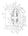
- FIG. 2 is an enlarged cross-sectional view of a valve case portion of a shock absorber according to one embodiment of the present invention.
- FIG. 3 is a bottom view of a valve case in the shock absorber according to one embodiment of the present invention.
- FIG. 4 is a perspective view of a valve case in a shock absorber according to one embodiment of the present invention, as viewed from below.
- FIG. 5 is a perspective view of a valve case in a shock absorber according to one embodiment of the present invention, as viewed from above.
- the shock absorber D in this embodiment includes a cylinder 1, a piston rod 2 inserted into the cylinder 1 so as to be movable in the axial direction, a piston 3 connected to the piston rod 2 and inserted into the cylinder 1 so as to be movable in the axial direction, and dividing the cylinder 1 into an expansion side chamber R1 and a compression side chamber R2, an outer cylinder 4 which is cylindrical with a bottom and houses the cylinder 1 therein and forms a reservoir R between the cylinder 1, and a valve case 5 which is sandwiched between the lower end 1a of the cylinder 1 in FIG. 1 and the bottom 4b of the outer cylinder 4 and divides the compression side chamber R2 and the reservoir R.
- the shock absorber D is used by being interposed between the vehicle body and the axle of a vehicle (not shown) to suppress vibration of the vehicle body and wheels.
- shock absorber D the upper end of cylinder 1 is closed by an annular rod guide 6 that fits into the upper end of outer cylinder 4, and the lower end is closed by fitting valve case 5. Then, cylinder 1 with rod guide 6 and valve case 5 fitted together is housed within outer cylinder 4.
- the outer tube 4 is a bottomed cylinder having a tube portion 4a and a bottom portion 4b that closes the lower end of the tube portion 4a in FIG. 1, and a crimped portion 4c formed by crimping the upper end of the tube portion 4a in FIG. 1 from the outer periphery toward the inside to form a flange.
- the bottom portion 4b also has a flat portion 4b1 provided at the lowest end in FIG. 1, and a cone-shaped outer periphery portion 4b2 that rises upward at an angle from the outer periphery of the flat portion 4b1, and the inner periphery of the outer periphery portion 4b2 forms a bottom side tapered surface 4b3.
- the rod guide 6 fitted to the upper end of the cylinder 1 has its small diameter portion at the bottom in FIG. 1 fitted to the inner circumference of the upper end of the cylinder 1, and its large diameter portion at the top in FIG. 1 fitted to the inner circumference of the tubular portion 4a of the outer tube 4.
- an annular seal member 7 fitted to the inner circumference of the tubular portion 4a of the outer tube 4 is laminated above the rod guide 6 in FIG. 1.
- the seal member 7, rod guide 6, cylinder 1, and valve case 5 are housed in the outer cylinder 4, and the upper end of the cylindrical portion 4a of the outer cylinder 4 in FIG. 1 is crimped from the outer periphery, whereby the seal member 7, rod guide 6, cylinder 1, and valve case 5 are clamped between the crimped portion 4c and the bottom portion 4b of the outer cylinder 4 and fixed within the outer cylinder 4.
- an annular gap is formed between the cylinder 1 and the outer cylinder 4, and this annular gap forms a reservoir R that stores liquid and gas.
- the piston rod 2 has a reduced outer diameter at the tip end, and is equipped with a small diameter section 2a with a small outer diameter at the tip end, a large diameter section 2b with a larger outer diameter than the small diameter section 2a and located above the small diameter section 2a in FIG. 1, a step section 2c located at the boundary between the small diameter section 2a and the large diameter section 2b, and a screw section 2d located on the outer periphery of the tip end of the small diameter section 2a.
- the piston rod 2 is inserted through the rod guide 6 and the inner circumference of the seal member 7 and inserted into the cylinder 1 so as to be movable in the axial direction, and a piston 3 is attached to the lower end in FIG. 1, which is the tip, so as to be movable in the axial direction within the cylinder 1 and to divide the inside of the cylinder 1 into an extension side chamber R1 and a compression side chamber R2.
- the seal member 7 seals between the piston rod 2 and the outer tube 4, sealing the inside of the cylinder 1 and the outer tube 4.
- the extension side chamber R1 and the compression side chamber R2 in the shock absorber D sealed in this way are filled with liquid, and the reservoir R is filled with a gas such as nitrogen gas or air.
- the liquid filled in the shock absorber D is hydraulic oil, but may be water, an aqueous solution, or other liquids other than hydraulic oil.
- the upper end of the piston rod 2 in FIG. 1 protrudes outside the cylinder 1, and although not shown, is provided at the upper end with a bracket that connects the piston rod 2 to one of the body and the axle of the vehicle.
- a bracket (not shown) is also provided on the bottom 4b of the outer cylinder 4, and the outer cylinder 4 is connected to the other of the body and the axle via the bracket (not shown).
- the shock absorber D is used by being interposed between the body and the axle, and when the vehicle runs on an uneven road surface and the wheels vibrate up and down relative to the body, the piston rod 2 moves in and out of the cylinder 1, the shock absorber D expands and contracts, and the piston 3 moves up and down (axially) within the cylinder 1.
- the piston 3 is fitted onto the outer periphery of the small diameter portion 2a of the piston rod 2 and is fixed to the piston rod 2 by a piston nut 8 that is screwed onto the threaded portion 2d of the piston rod 2.
- the piston 3 is attached to the piston rod 2, and its outer periphery is in sliding contact with the inner periphery of the cylinder 1, dividing the inside of the cylinder 1 into an extension side chamber R1 and a compression side chamber R2 as working chambers.
- the piston 3 is also annular and has an extension side port 3a and a compression side port 3b that communicate between the extension side chamber R1 and the compression side chamber R2.
- the extension side leaf valve 9 is stacked below the piston 3 in FIG. 1.
- the extension side leaf valve 9 is a stacked leaf valve formed by stacking multiple annular plates, stacked at the lower end of the piston 3 in FIG. 1, and fixed to the outer periphery of the small diameter portion 2a of the piston rod 2 together with the piston 3.
- the extension side leaf valve 9 is stacked at the lower end of the piston 3 and its inner periphery is fixed to the outer periphery of the small diameter portion 2a of the piston rod 2, allowing it to bend in a direction away from the piston 3 on the outer periphery side, and can open and close the outlet end, which is the lower end in FIG. 1, of the extension side port 3a provided in the piston 3.
- a circular check valve 10 is stacked above the piston 3.
- the check valve 10 is a perforated check valve with a circular hole 10a in the radial center, and when stacked on the piston 3, it closes the outlet end of the compression side port 3b, which is the upper end in FIG. 1, but communicates with the expansion side port 3a and the expansion side chamber R1 via the hole 10a.
- a cylindrical collar 11, a spring member 12 that urges the check valve 10 toward the piston 3, and a circular valve stopper 13 are stacked above the check valve 10 in FIG. 1.
- the spring member 12 is a conical coil spring, and is interposed between the check valve 10 and the valve stopper 13 in a compressed state, urging the check valve 10 toward the piston 3 at all times.
- the spring member 12 may be an elastic body other than a conical coil spring, and although not specifically shown, may be a spring having a ring laminated on the upper end of the collar 11 in FIG. 1 and a plurality of arms extending radially downward from the outer circumference of the ring and contacting the back surface of the check valve 10, which is the side opposite the piston, to bias the check valve 10 toward the piston.
- the spring member 12 is provided to help the check valve 10 quickly return to the position where it closes the compression side port 3b after it is deflected, but may be omitted if unnecessary.
- the check valve 10 is fixed on its inner circumference to the outer circumference of the small diameter section 2a of the piston rod 2, allowing the outer circumference to flex. When it is stacked on the piston 3, it closes the compression side port 3b, and when the outer circumference flexes and compresses the spring member 12, separating it from the piston 3, it opens the compression side port 3b, allowing liquid to flow through the compression side port 3b from the compression side chamber R2 to the extension side chamber R1 with almost no resistance.
- valve stopper 13, spring member 12, collar 11, check valve 10, piston 3 and extension side leaf valve 9 are assembled in order to the outer circumference of the small diameter portion 2a of the piston rod 2, and then fixed to the piston rod 2 by being clamped between the piston nut 8, which is screwed to the threaded portion 2d of the small diameter portion 2a, and the step portion 2c of the piston rod 2.
- the valve case 5 has a disk-shaped main body 5a, five legs 5b that protrude downward from the lower end of the main body 5a in Figure 2, and five ribs 5c that protrude downward from between the legs 5b, 5b at the lower end of the main body 5a in Figure 2.
- the main body 5a is disk-shaped with a hole in the center, and the outer diameter changes halfway in the axial direction.
- the main body 5a has a small diameter portion 5a1 with a small outer diameter on the upper side and a large diameter portion 5a2 with a large outer diameter on the lower side, thereby forming a step portion 5a3 on the outer periphery. It also has six exhaust ports 5a4 that penetrate the main body 5a in the axial direction, five suction ports 5a5 that penetrate the main body 5a in the axial direction, an annular exhaust side seat portion 5a6 that protrudes downward in FIG.
- the six exhaust ports 5a4 provided on the main body 5a are equally spaced on the same circumference of the main body 5a, and the five suction ports 5a5 are equally spaced on the same circumference on the outer periphery of the main body 5a, away from the exhaust ports 5a4.
- the number of exhaust ports 5a4 and suction ports 5a5 provided can be changed as desired.
- the discharge side sheet portion 5a6 is annular and protrudes downward from the lower end of the main body portion 5a between the discharge port 5a4 and the suction port 5a5 to surround the outer periphery of the discharge port 5a4.
- the suction side sheet portion 5a7 is annular and protrudes upward from the outer periphery of the suction port 5a5 to surround the outer periphery of the suction port 5a5 at the upper end of the main body portion 5a.
- the legs 5b protrude downward toward the bottom 4b side at intervals from the outer peripheral side of the lower open end of the suction port 5a5 at the bottom side end of the bottom end 4b side of the outer tube 4 of the main body 5a in FIG. 2.
- Five legs 5b are provided intermittently in the circumferential direction on the valve case 5. More specifically, as shown in FIG. 3 and FIG. 4, the legs 5b are installed on the outer peripheral side between the suction ports 5a5, 5a5 in the circumferential direction of the main body 5a so as not to overlap with the suction port 5a5 in the radial direction. Therefore, the legs 5b are provided in a position where they do not act as a dam to obstruct the flow of liquid from the reservoir R toward the suction port 5a5.
- the leg 5b has a circumferential width that narrows toward the bottom of the outer tube 4 in the circumferential direction of the valve case 5, and the circumferential side surfaces are inclined surfaces 5b1, 5b1.
- the outer periphery of the bottom side surface of the leg 5b which is the tip surface facing the bottom 4b of the outer tube 4 is provided with a leg side tapered surface 5b2 that is inclined so that the radial width of the leg 5b narrows toward the tip, and the inside of the leg side tapered surface 5b2 on the bottom side surface of the leg 5b is a flat surface 5b3.
- the leg side tapered surface 5b2 extends toward the inner periphery of the valve case 5 beyond the circle that passes through the inner circumference of the step 5a3 of the main body 5a when the valve case 5 is viewed in the axial direction.
- a curved portion 5b4 is provided at the base of the main body 5a on the inner peripheral side of the leg 5b facing the inside of the valve case 5 so that the thickness increases in the inward direction, and the radial width of the base portion to the main body 5a is wider in the cross section of the leg 5b, and the radial thickness of the base portion is thicker than the tip side of the leg 5b. Therefore, even if the leg 5b is sandwiched between the cylinder 1 and the bottom 4b of the outer tube 4 and receives an axial load, the base portion of the leg 5b to the main body 5a is reinforced by the curved portion 5b4, and deformation such as the leg 5b collapsing toward the inner peripheral side of the valve case 5 is prevented.
- an inclined portion may be provided so that the radial width of the base portion to the main body 5a is wider in the cross section of the leg 5b.
- the rib 5c also protrudes downward from between the legs 5b, 5b at the bottom end of the main body 5a (see FIG. 2).
- the rib 5c is arc-shaped when the valve case 5 is viewed in the axial direction
- the rib 5c has a horizontal arc-shaped surface 5c1 that is horizontal to the axial direction and is highest at the center in the radial direction, an outer peripheral tapered surface 5c2 that is connected to the outer periphery of the horizontal surface 5c1, and an inner peripheral tapered surface 5c3 that is connected to the inner periphery of the horizontal surface 5c1.
- Both circumferential ends of the rib 5c are connected to the sides of the legs 5b, which increases the strength of the legs 5b and suppresses deformation of the legs 5b when the legs 5b are subjected to an axial load.
- the valve case 5 thus constructed is housed in the outer cylinder 4 with the small diameter portion 5a1 of the main body 5a fitted to the inner circumference of the lower end of the cylinder 1, and the leg side tapered surface 5b2 of the bottom end of the leg 5b is abutted against the bottom side tapered surface 4b3 at the bottom 4b of the outer cylinder 4, and is fixed in the outer cylinder 4 by being clamped between the crimped portion 4c of the outer cylinder 4 and the bottom 4b.
- the leg side tapered surface 5b2 is preferably in surface contact with the bottom side tapered surface 4b3, but may also be in partial contact with the bottom side tapered surface 4b3.
- the valve case 5 can be centered with respect to the outer cylinder 4, and radial positional deviation of the valve case 5 with respect to the outer cylinder 4 can be suppressed .
- an axial load acts on the outer periphery of the large diameter portion 5a2 of the main body 5a sandwiched between the cylinder 1 and the bottom 4b of the valve case 5 and on the leg 5b. Since the lower end of the cylinder 1 abuts on the step 5a3, the axial load acts on the range of the step 5a3 when the valve case 5 is viewed in the axial direction.
- leg side tapered surface 5b2 of the leg 5b extends to the inner periphery of the valve case 5 beyond the circle passing through the inner periphery of the step 5a3 of the main body 5a when the valve case 5 is viewed in the axial direction, the line of action of the load does not pass through the flat surface 5b3 on the inner periphery of the bottom end of the leg 5b. Therefore, no moment that causes the bottom end of the leg 5b to open to the outer periphery acts on the leg 5b due to the load, and bending deformation of the leg 5b due to the load can be suppressed.
- the compression side leaf valve 14 is stacked at the bottom of the valve case 5 in FIG. 1.
- the compression side leaf valve 14 is a stacked leaf valve formed by stacking multiple annular plates, stacked at the bottom end of the valve case 5 in FIG. 2, and fixed to the outer periphery of the center rod 15 inserted into the inner periphery of the main body 5a of the valve case 5. Since the inner periphery of the compression side leaf valve 14 is fixed to the center rod 15, it is allowed to bend in a direction away from the valve case 5 on the outer periphery, and can be seated on and removed from the discharge side seat portion 5a6 provided on the valve case 5 to open and close the outlet end, which is the lower end of the discharge port 5a4 in FIG. 2.
- the center rod 15 has a shaft portion 15a that is inserted into the inner circumference of the main body portion 5a of the valve case 5, a lower flange 15b provided at the lower end of the shaft portion 15a in FIG. 2, and an upper flange 15c provided at the tip of the shaft portion 15a in FIG. 2.
- the lower flange 15b and the valve case 5 sandwich the inner circumference of the compression side leaf valve 14.
- annular check valve 16 is stacked on the upper part of the valve case 5 in FIG. 2.
- the check valve 16 is a perforated check valve with an annular hole 16a in the radial center, and is attached to the outer periphery of the shaft portion 15a of the center rod 15.
- the check valve 16 seats on the suction side seat portion 5a7 and closes the outlet end, which is the upper end in FIG. 1, of the suction port 5a5, but communicates between the exhaust port 5a4 and the compression side chamber R2 via the hole 10a.
- a cylindrical collar 17, a spring member 18 that urges the check valve 16 toward the valve case 5, and an annular valve stopper 20 are stacked.
- the spring member 18 is a conical coil spring, and is interposed between the check valve 16 and the valve stopper 20 in a compressed state to constantly urge the check valve 16 toward the valve case 5.
- the spring member 18 may be an elastic body other than a conical coil spring, and although not specifically shown, may be a spring having a ring stacked on the upper end of the collar 17 in FIG. 1 and a plurality of arms that extend radially downward from the outer periphery of the ring and abut against the back surface of the check valve 16, which is the side opposite the piston, to urge the check valve 16 toward the piston.
- the spring member 18 is provided to help the check valve 16 to quickly return to a position that blocks the suction port 5a5 after bending, but may be omitted if unnecessary.
- valve stopper 20, spring member 18, collar 17, check valve 16, valve case 5 and compression side leaf valve 14 are fitted onto the outer periphery of the shaft portion 15a of the center rod 15 and are fixed to the center rod 15 by being sandwiched between the lower flange 15b and upper flange 15c of the center rod 15.
- the shock absorber D is constructed as described above, and its operation is described below.
- the shock absorber D performs an extension operation and the piston 3 moves upward in FIG. 1 relative to the cylinder 1
- the upward movement of the piston 3 in FIG. 1 causes the liquid in the expansion-side chamber R1, which is compressed, to bend the expansion-side leaf valve 9 and move through the expansion-side port 3a to the compression-side chamber R2.
- the expansion-side leaf valve 9 provides resistance to the flow of liquid from the expansion-side chamber R1 to the compression-side chamber R2, so the pressure in the expansion-side chamber R1 rises.
- shock absorber D expands, liquid equivalent to the volume of piston rod 2 exiting cylinder 1 pushes open check valve 16 and moves from reservoir R to pressure side chamber R2 via suction port 5a5. Because check valve 16 offers almost no resistance to the flow of liquid passing through suction port 5a5, the pressure in pressure side chamber R2 becomes nearly equal to the pressure in reservoir R.
- shock absorber D when shock absorber D is extended, the pressure in the extension side chamber R1 rises, and the pressure in the compression side chamber R2 becomes approximately equal to the pressure in the reservoir R, creating a difference between the pressure in the extension side chamber R1 and the pressure in the compression side chamber R2, causing shock absorber D to generate a damping force that impedes the extension operation.
- check valve 16 opens and the volume of liquid that the piston rod 2 withdraws from the cylinder 1 is supplied from the reservoir R to the cylinder 1, thereby compensating for the volume of liquid that the piston rod 2 withdraws from the cylinder 1.
- the rib 5c provided between the legs 5b, 5b at the lower end of the main body 5a of the valve case 5 has an outer peripheral tapered surface 5c2 that slopes away from the bottom 4b of the outer tube 4 on the outer periphery, so that even if the strength of the legs 5b is increased by providing the rib 5c, the degree of reduction in the opening area between the legs 5b, 5b can be reduced, and the opening area can be sufficiently secured.
- the rib 5c has an inner peripheral tapered surface 5c3 that slopes away from the bottom 4b of the outer tube 4 on the inner periphery, and a horizontal surface 5c1 formed between the outer peripheral tapered surface 5c2 and the inner peripheral tapered surface 5c3, so that liquid that has entered between the legs 5b, 5b from the reservoir R can move smoothly without resistance along the horizontal surface 5c1 and the inner peripheral tapered surface 5c3 to the suction port 5a5 located on the inner periphery of the legs 5b.
- shock absorber D contracts, the liquid in cylinder 1 becomes excessive due to the volume of piston rod 2 penetrating into cylinder 1, and the liquid pushes open compression side leaf valve 14 and moves from compression side chamber R2 to reservoir R via exhaust port 5a4. Since compression side leaf valve 14 provides resistance to the flow of liquid from compression side chamber R2 to reservoir R, check valve 10 opens and the pressure in compression side chamber R2 and extension side chamber R1, which are in communication with each other, rises almost equally. In this way, when shock absorber D contracts, the liquid in cylinder 1 equivalent to the volume of piston rod 2 penetrating into cylinder 1 is discharged to reservoir R from within cylinder 1, compensating for the volume of piston rod 2 penetrating into cylinder 1.
- the shock absorber D of this embodiment is a single-rod type shock absorber in which the piston rod 2 is inserted only into the extension-side chamber R1, and the pressure-receiving area of the piston 3 that receives the pressure in the compression-side chamber R2 is larger than the pressure-receiving area that receives the pressure in the extension-side chamber R1 by the cross-sectional area of the piston rod 2, so that when the pressures in the compression-side chamber R2 and the extension-side chamber R1 are approximately equal, the piston 3 receives a force in a direction that pushes the piston rod 2 out of the cylinder 1. Therefore, when the shock absorber D performs a contraction operation, it generates a damping force in a direction that pushes the piston rod 2 out of the cylinder 1, thereby hindering the contraction operation.
- the shock absorber D of this embodiment includes a cylinder 1, a piston rod 2 inserted into the cylinder 1 so as to be movable in the axial direction, a piston 3 connected to the piston rod 2 and inserted into the cylinder 1 so as to be movable in the axial direction, and dividing the cylinder 1 into an expansion side chamber R1 and a compression side chamber R2, an outer tube 4 having a bottom and accommodating the cylinder 1 therein and forming a reservoir R between the cylinder 1 and the outer tube 4, and a valve case 5 sandwiched between the end of the cylinder 1 and the bottom 4b of the outer tube 4 to separate the compression side chamber R2 and the reservoir R.
- the valve case 5 is disc-shaped and has an outer diameter of 1.5 mm.
- the body 5a has a small diameter portion 5a1 and a large diameter portion 5a2 separated by a step 5a3 that abuts against the end 1a of the cylinder 1, and the small diameter portion 5a1 is fitted to the inner circumference of the cylinder 1 and has a suction port (port) 5a5 that connects the pressure side chamber R2 to the reservoir R.
- the body 5a has a plurality of legs 5b that are spaced apart circumferentially on the outer periphery of the bottom end of the body 5a that faces the bottom side of the outer tube 4, protruding from the bottom end toward the bottom 4b and abutting against the bottom 4b.
- the circumferential width of the legs 5b is shorter than the circumferential distance between the legs 5b, 5b, and the circumferential width of the legs 5b narrows toward the bottom side of the outer tube 4.
- the circumferential width of the legs 5b of the valve case 5 narrows toward the bottom side of the outer cylinder 4, and the circumferential side of the legs 5b is inclined, and the spacing between the legs 5b widens toward the tip, so that the opening area between the legs 5b can be secured without increasing the length of the legs 5b in the axial direction of the valve case 5. Also, since the overall length of the legs 5b does not need to be increased, the slenderness ratio of the legs 5b can be reduced, so that even if a wide opening area between the legs 5b is secured, the decrease in strength of the legs 5b can be kept to a small extent, and there is no risk of insufficient strength.
- a wide opening area between the legs 5b, 5b can be ensured without increasing the overall length of the legs 5b, so the overall length of the shock absorber D is not increased and the stroke length is not sacrificed, and resistance can be reduced when the liquid passes between the legs 5b, 5b during the extension operation.
- deformation and buckling of the valve case 5 are prevented, while a stable damping force can be generated without impairing mountability on the vehicle.
- the circumferential width of the leg 5b is shorter than the circumferential distance between the legs 5b, 5b
- the circumferential width of the tip of the leg 5b is shorter than the circumferential distance between the tips of the legs 5b, 5b
- the circumferential width of the base of the leg 5b is shorter than the circumferential distance between the bases of the legs 5b, 5b.
- the circumferential width of the base of the leg 5b is made shorter than the circumferential distance between the bases of the legs 5b, 5b, the strength of the legs 5b, 5b can be ensured, and deformation and buckling of the valve case 5 can be further prevented.
- the circumferential side of the leg 5b is an inclined surface 5b1, 5b1 over the entire length from the top to the bottom in Fig. 2, and the circumferential width of the leg 5b gradually narrows as it approaches the bottom side of the outer tube 4, but the side of the leg 5b from midway in the vertical direction in Fig. 2 to the base side to the main body 5a may be an inclined surface, and the side of the leg 5b from midway in the vertical direction in Fig. 2 to the side opposite the main body may be a vertical surface, so that the circumferential width of the tip side of the bottom side of the leg 5b is narrower than the circumferential width of the base side. Conversely, the side of the leg 5b from midway in the vertical direction in Fig.
- the side of the leg 5b from midway in the vertical direction in Fig. 2 to the side opposite the main body may be an inclined surface, so that the circumferential width of the tip side of the bottom side of the leg 5b is narrower than the circumferential width of the base side.
- the side of the leg 5b may be formed in a stepped shape so that the circumferential width of the leg 5b narrows in stages toward the bottom of the outer cylinder 4. This also ensures the strength of the leg 5b while ensuring a wide opening area between the legs 5b, 5b, preventing deformation or buckling of the valve case 5 and generating a stable damping force without impairing the mountability on the vehicle.
- the valve case 5 of the shock absorber D of this embodiment also has a rib 5c that protrudes from between the legs 5b, 5b at the bottom end of the main body 5a toward the bottom side and is connected to the legs 5b.
- the valve case 5 has a rib 5c connected to the legs 5b, so even if the circumferential width of the legs 5b is narrowed toward the bottom side of the outer tube 4, the legs 5b can be reinforced by the rib 5c, and the thickness from the step 5a3 of the main body 5a to the horizontal surface 5c1 of the rib 5c can be secured, and the strength of the main body 5a is also improved.
- the strength of the valve case 5 can be improved and deformation of the valve case 5 can be further suppressed, so that the interval between the legs 5b, 5b can be made wider and the opening area between the legs 5b, 5b can be secured.
- the leg 5b of the valve case 5 of the shock absorber D of this embodiment has a curved portion 5b4 that widens the radial width on the inner circumference at the base of the main body 5a.
- the shock absorber D configured in this manner, the strength of the base portion of the main body 5a of the leg 5b is improved, so that even if the leg 5b is sandwiched between the cylinder 1 and the bottom 4b of the outer tube 4 and receives an axial load, the leg 5b is prevented from deforming so as to collapse toward the inner circumference of the valve case 5.
- the strength of the valve case 5 can be improved and deformation of the valve case 5 can be further suppressed, making it easier to widen the gap between the legs 5b, 5b and ensure the opening area between the legs 5b, 5b.
- the rib 5c in the valve case 5 of the shock absorber D in this embodiment is arc-shaped when the valve case 5 is viewed in the axial direction, and has an outer peripheral tapered surface 5c2 provided on the outer circumference, an inner peripheral tapered surface 5c3 provided on the inner circumference, and a horizontal surface 5c1 formed between the outer peripheral tapered surface 5c2 and the inner peripheral tapered surface 5c3.
- the rib 5c has an outer peripheral tapered surface 5c2 that slopes away from the bottom 4b of the outer tube 4 on the outer periphery.
- the rib 5c has an inner peripheral tapered surface 5c3 that slopes away from the bottom 4b of the outer tube 4 on the inner periphery, and a horizontal surface 5c1 formed between the outer peripheral tapered surface 5c2 and the inner peripheral tapered surface 5c3. Therefore, liquid that has entered between the legs 5b, 5b from the reservoir R can move smoothly along the horizontal surface 5c1 and the inner peripheral tapered surface 5c3 to the suction port 5a5 located on the inner periphery of the leg 5b without resistance.
- the bottom 4b of the outer tube 4 of the shock absorber D of this embodiment has a mortar-shaped bottom side tapered surface 4b3 on the inner periphery, and the inclination angle ⁇ of the bottom side tapered surface 4b3 with respect to a plane perpendicular to the outer tube 4 is equal to or greater than the inclination angle ⁇ of the outer peripheral tapered surface 5c2 with respect to a plane perpendicular to the outer tube 4.
- the shock absorber D configured in this manner, the distance between the outer peripheral tapered surface 5c2 of the rib 5c and the bottom side tapered surface 4b3 at the bottom 4b of the outer tube 4 does not approach the outer periphery of the valve case 5, and the opening area facing the reservoir R between the legs 5b, 5b is not reduced. Therefore, with the shock absorber D, the bottom side tapered surface 4b3 is provided on the bottom 4b of the outer tube 4 and abuts against the leg side tapered surface 5b2 of the leg 5b of the valve case 5 to improve the seating of the valve case 5 with respect to the outer tube 4, and the opening area between the legs 5b, 5b can be secured while aligning the valve case 5 with respect to the outer tube 4.
- the legs 5b in the valve case 5 of the shock absorber D of this embodiment have a leg-side tapered surface 5b2 on the outer periphery of the bottom side, and the leg-side tapered surface 5b2 extends further inward than a circle passing through the inner periphery of the step portion 5a3 when the valve case 5 is viewed in the axial direction.
- the shock absorber D configured in this way, even if an axial load acts on the outer periphery of the large diameter portion 5a2 of the main body 5a of the valve case 5 and the legs 5b when the valve case 5 is clamped between the cylinder 1 and the bottom 4b of the outer tube 4, the line of action of the load does not pass through the inner periphery of the leg-side tapered surface 5b2 of the legs 5b, so no moment acts that opens the bottom end of the legs 5b toward the outer periphery, and bending deformation of the legs 5b due to the load can be suppressed.
Landscapes
- Engineering & Computer Science (AREA)
- General Engineering & Computer Science (AREA)
- Mechanical Engineering (AREA)
- Fluid-Damping Devices (AREA)
Priority Applications (1)
| Application Number | Priority Date | Filing Date | Title |
|---|---|---|---|
| JP2025548623A JPWO2025069856A1 (https=) | 2023-09-27 | 2024-08-27 |
Applications Claiming Priority (2)
| Application Number | Priority Date | Filing Date | Title |
|---|---|---|---|
| JP2023-164183 | 2023-09-27 | ||
| JP2023164183 | 2023-09-27 |
Publications (1)
| Publication Number | Publication Date |
|---|---|
| WO2025069856A1 true WO2025069856A1 (ja) | 2025-04-03 |
Family
ID=95202532
Family Applications (1)
| Application Number | Title | Priority Date | Filing Date |
|---|---|---|---|
| PCT/JP2024/030415 Pending WO2025069856A1 (ja) | 2023-09-27 | 2024-08-27 | 緩衝器 |
Country Status (2)
| Country | Link |
|---|---|
| JP (1) | JPWO2025069856A1 (https=) |
| WO (1) | WO2025069856A1 (https=) |
Citations (5)
| Publication number | Priority date | Publication date | Assignee | Title |
|---|---|---|---|---|
| JPS60130435A (ja) * | 1983-12-20 | 1985-07-11 | Tokico Ltd | 油圧緩衝器用バルブガイドの製造方法 |
| JPH11344069A (ja) * | 1998-04-01 | 1999-12-14 | Kayaba Ind Co Ltd | 油圧緩衝器の減衰力発生構造 |
| US20020179388A1 (en) * | 2001-05-31 | 2002-12-05 | Moradmand Jamshid Kargar | Modular blow-off valve for automotive damper |
| CN203926573U (zh) * | 2014-07-10 | 2014-11-05 | 宁波金恒汽车零部件有限公司 | 减震器的阀座 |
| JP2022144363A (ja) * | 2021-03-19 | 2022-10-03 | Kyb株式会社 | バルブおよび緩衝器 |
-
2024
- 2024-08-27 JP JP2025548623A patent/JPWO2025069856A1/ja active Pending
- 2024-08-27 WO PCT/JP2024/030415 patent/WO2025069856A1/ja active Pending
Patent Citations (5)
| Publication number | Priority date | Publication date | Assignee | Title |
|---|---|---|---|---|
| JPS60130435A (ja) * | 1983-12-20 | 1985-07-11 | Tokico Ltd | 油圧緩衝器用バルブガイドの製造方法 |
| JPH11344069A (ja) * | 1998-04-01 | 1999-12-14 | Kayaba Ind Co Ltd | 油圧緩衝器の減衰力発生構造 |
| US20020179388A1 (en) * | 2001-05-31 | 2002-12-05 | Moradmand Jamshid Kargar | Modular blow-off valve for automotive damper |
| CN203926573U (zh) * | 2014-07-10 | 2014-11-05 | 宁波金恒汽车零部件有限公司 | 减震器的阀座 |
| JP2022144363A (ja) * | 2021-03-19 | 2022-10-03 | Kyb株式会社 | バルブおよび緩衝器 |
Also Published As
| Publication number | Publication date |
|---|---|
| JPWO2025069856A1 (https=) | 2025-04-03 |
Similar Documents
| Publication | Publication Date | Title |
|---|---|---|
| JP5115814B2 (ja) | 緩衝器 | |
| JP6838768B2 (ja) | 緩衝器 | |
| JP5758235B2 (ja) | 緩衝器 | |
| US20090038897A1 (en) | Shock absorber | |
| US20140252735A1 (en) | Shock absorber | |
| CN108012552A (zh) | 频率可选阻尼阀和包括该阻尼阀的减震器 | |
| WO2018062151A1 (ja) | 緩衝器 | |
| EP3333446B1 (en) | Valve structure for buffer | |
| WO2025069856A1 (ja) | 緩衝器 | |
| JPWO2019069413A1 (ja) | 圧力緩衝装置および減衰力発生機構 | |
| WO2019194168A1 (ja) | バルブ及び緩衝器 | |
| JP6626631B2 (ja) | 緩衝器 | |
| JP7070331B2 (ja) | ハイドロストッパ付ショックアブソーバ | |
| JPH08121524A (ja) | ショックアブソーバ | |
| JP7523695B2 (ja) | 緩衝器 | |
| JP6997666B2 (ja) | 緩衝器 | |
| JP7541197B2 (ja) | 緩衝器 | |
| WO2024232211A1 (ja) | 緩衝器 | |
| JP7506634B2 (ja) | 緩衝器 | |
| JP4868166B2 (ja) | 流体圧緩衝器 | |
| JP2025139653A (ja) | チェックバルブ | |
| JP7482204B1 (ja) | 緩衝器 | |
| WO2025062925A1 (ja) | バルブおよび緩衝器 | |
| JP7738494B2 (ja) | 緩衝器 | |
| CN119790247A (zh) | 缓冲器 |
Legal Events
| Date | Code | Title | Description |
|---|---|---|---|
| 121 | Ep: the epo has been informed by wipo that ep was designated in this application |
Ref document number: 24871657 Country of ref document: EP Kind code of ref document: A1 |
|
| ENP | Entry into the national phase |
Ref document number: 2025548623 Country of ref document: JP Kind code of ref document: A |