WO2025069738A1 - 固体電池 - Google Patents
固体電池 Download PDFInfo
- Publication number
- WO2025069738A1 WO2025069738A1 PCT/JP2024/028628 JP2024028628W WO2025069738A1 WO 2025069738 A1 WO2025069738 A1 WO 2025069738A1 JP 2024028628 W JP2024028628 W JP 2024028628W WO 2025069738 A1 WO2025069738 A1 WO 2025069738A1
- Authority
- WO
- WIPO (PCT)
- Prior art keywords
- solid
- solid electrolyte
- state battery
- crystal structure
- oxide ceramic
- Prior art date
- Legal status (The legal status is an assumption and is not a legal conclusion. Google has not performed a legal analysis and makes no representation as to the accuracy of the status listed.)
- Pending
Links
Images


Classifications
-
- H—ELECTRICITY
- H01—ELECTRIC ELEMENTS
- H01M—PROCESSES OR MEANS, e.g. BATTERIES, FOR THE DIRECT CONVERSION OF CHEMICAL ENERGY INTO ELECTRICAL ENERGY
- H01M50/00—Constructional details or processes of manufacture of the non-active parts of electrochemical cells other than fuel cells, e.g. hybrid cells
- H01M50/10—Primary casings; Jackets or wrappings
- H01M50/116—Primary casings; Jackets or wrappings characterised by the material
- H01M50/117—Inorganic material
-
- C—CHEMISTRY; METALLURGY
- C01—INORGANIC CHEMISTRY
- C01G—COMPOUNDS CONTAINING METALS NOT COVERED BY SUBCLASSES C01D OR C01F
- C01G23/00—Compounds of titanium
-
- C—CHEMISTRY; METALLURGY
- C01—INORGANIC CHEMISTRY
- C01G—COMPOUNDS CONTAINING METALS NOT COVERED BY SUBCLASSES C01D OR C01F
- C01G29/00—Compounds of bismuth
-
- C—CHEMISTRY; METALLURGY
- C04—CEMENTS; CONCRETE; ARTIFICIAL STONE; CERAMICS; REFRACTORIES
- C04B—LIME, MAGNESIA; SLAG; CEMENTS; COMPOSITIONS THEREOF, e.g. MORTARS, CONCRETE OR LIKE BUILDING MATERIALS; ARTIFICIAL STONE; CERAMICS; REFRACTORIES; TREATMENT OF NATURAL STONE
- C04B35/00—Shaped ceramic products characterised by their composition; Ceramics compositions; Processing powders of inorganic compounds preparatory to the manufacturing of ceramic products
- C04B35/01—Shaped ceramic products characterised by their composition; Ceramics compositions; Processing powders of inorganic compounds preparatory to the manufacturing of ceramic products based on oxide ceramics
- C04B35/46—Shaped ceramic products characterised by their composition; Ceramics compositions; Processing powders of inorganic compounds preparatory to the manufacturing of ceramic products based on oxide ceramics based on titanium oxides or titanates
- C04B35/462—Shaped ceramic products characterised by their composition; Ceramics compositions; Processing powders of inorganic compounds preparatory to the manufacturing of ceramic products based on oxide ceramics based on titanium oxides or titanates based on titanates
-
- H—ELECTRICITY
- H01—ELECTRIC ELEMENTS
- H01M—PROCESSES OR MEANS, e.g. BATTERIES, FOR THE DIRECT CONVERSION OF CHEMICAL ENERGY INTO ELECTRICAL ENERGY
- H01M10/00—Secondary cells; Manufacture thereof
- H01M10/05—Accumulators with non-aqueous electrolyte
- H01M10/052—Li-accumulators
-
- H—ELECTRICITY
- H01—ELECTRIC ELEMENTS
- H01M—PROCESSES OR MEANS, e.g. BATTERIES, FOR THE DIRECT CONVERSION OF CHEMICAL ENERGY INTO ELECTRICAL ENERGY
- H01M10/00—Secondary cells; Manufacture thereof
- H01M10/05—Accumulators with non-aqueous electrolyte
- H01M10/056—Accumulators with non-aqueous electrolyte characterised by the materials used as electrolytes, e.g. mixed inorganic/organic electrolytes
- H01M10/0561—Accumulators with non-aqueous electrolyte characterised by the materials used as electrolytes, e.g. mixed inorganic/organic electrolytes the electrolyte being constituted of inorganic materials only
- H01M10/0562—Solid materials
-
- H—ELECTRICITY
- H01—ELECTRIC ELEMENTS
- H01M—PROCESSES OR MEANS, e.g. BATTERIES, FOR THE DIRECT CONVERSION OF CHEMICAL ENERGY INTO ELECTRICAL ENERGY
- H01M50/00—Constructional details or processes of manufacture of the non-active parts of electrochemical cells other than fuel cells, e.g. hybrid cells
- H01M50/10—Primary casings; Jackets or wrappings
- H01M50/14—Primary casings; Jackets or wrappings for protecting against damage caused by external factors
- H01M50/141—Primary casings; Jackets or wrappings for protecting against damage caused by external factors for protecting against humidity
-
- H—ELECTRICITY
- H01—ELECTRIC ELEMENTS
- H01M—PROCESSES OR MEANS, e.g. BATTERIES, FOR THE DIRECT CONVERSION OF CHEMICAL ENERGY INTO ELECTRICAL ENERGY
- H01M10/00—Secondary cells; Manufacture thereof
- H01M10/05—Accumulators with non-aqueous electrolyte
- H01M10/058—Construction or manufacture
- H01M10/0585—Construction or manufacture of accumulators having only flat construction elements, i.e. flat positive electrodes, flat negative electrodes and flat separators
-
- H—ELECTRICITY
- H01—ELECTRIC ELEMENTS
- H01M—PROCESSES OR MEANS, e.g. BATTERIES, FOR THE DIRECT CONVERSION OF CHEMICAL ENERGY INTO ELECTRICAL ENERGY
- H01M2300/00—Electrolytes
- H01M2300/0017—Non-aqueous electrolytes
- H01M2300/0065—Solid electrolytes
- H01M2300/0068—Solid electrolytes inorganic
-
- Y—GENERAL TAGGING OF NEW TECHNOLOGICAL DEVELOPMENTS; GENERAL TAGGING OF CROSS-SECTIONAL TECHNOLOGIES SPANNING OVER SEVERAL SECTIONS OF THE IPC; TECHNICAL SUBJECTS COVERED BY FORMER USPC CROSS-REFERENCE ART COLLECTIONS [XRACs] AND DIGESTS
- Y02—TECHNOLOGIES OR APPLICATIONS FOR MITIGATION OR ADAPTATION AGAINST CLIMATE CHANGE
- Y02E—REDUCTION OF GREENHOUSE GAS [GHG] EMISSIONS, RELATED TO ENERGY GENERATION, TRANSMISSION OR DISTRIBUTION
- Y02E60/00—Enabling technologies; Technologies with a potential or indirect contribution to GHG emissions mitigation
- Y02E60/10—Energy storage using batteries
Definitions
- the present invention relates to solid-state batteries.
- Patent Documents 1 to 4 propose a solid-state battery having an exterior part containing oxide ceramics on the outer surface of a battery element having a positive electrode layer, a negative electrode layer, and a solid electrolyte layer between them.
- insulating parts are disposed between the positive electrode layer and the negative external electrode, and between the negative electrode layer and the positive external electrode, and attempts have been made to include oxide ceramics in such insulating parts.
- the exterior portion contains an oxide ceramic containing one or more elements (M) selected from the group consisting of Li (lithium), Mg (magnesium), and elements of groups 4 and 5, the reaction can be prevented to some extent, but the prevention effect is not sufficient. For this reason, attempts have been made to prevent the reaction more sufficiently by firing at a relatively low temperature (for example, 1000°C or lower), but this creates new problems in that the exterior portion does not densify sufficiently at such low temperatures, increasing the areal porosity and decreasing moisture resistance.
- M elements
- the oxide ceramics contained in the insulating part contains oxide ceramics containing one or more elements (M) selected from the group consisting of Li (lithium), Mg (magnesium) and elements of groups 4 and 5, the reaction can be prevented to some extent, but the prevention effect is not sufficient. For this reason, attempts have been made to prevent the reaction more sufficiently by firing at a relatively low temperature (for example, 1000°C or lower), as in the case where the exterior part contains oxide ceramics.
- M elements
- the insulating part does not become sufficiently densified at such a low temperature.
- the insulating part does not directly contact the surrounding environment (for example, air), air may enter through voids generated in the external electrode and/or air may enter between the external electrode and the battery element, so it was important for the insulating part to have moisture resistance.
- the insulating part is required to be densely sintered to improve its moisture resistance and to prevent side reactions with the solid electrolyte.
- the present invention aims to provide a solid-state battery that has excellent low-temperature densification characteristics and moisture resistance.
- the present invention also aims to provide a solid-state battery that is more sufficiently superior in terms of low-temperature densification characteristics and moisture resistance, as well as reactivity resistance.
- the present invention relates to It has an exterior part and an insulating part, At least one of the exterior part and the insulating part is Li (lithium); Mg (Magnesium); One or more elements (M) selected from the group consisting of elements of Groups 4 and 5; and Bi (bismuth)
- Li lithium
- Mg Magnium
- M Magnium
- M elements
- Bi bismuth
- the present invention relates to a solid-state battery comprising an oxide ceramic containing
- a solid-state battery having sufficiently excellent low-temperature densification characteristics and moisture resistance can be provided.
- an exterior part and/or an insulating part is formed in which the area porosity is sufficiently reduced even at a relatively low temperature (for example, 1000° C. or less (particularly 800° C. or less)), and the water vapor transmission rate (WVTR) is sufficiently reduced even under high temperature and high humidity conditions.
- a relatively low temperature for example, 1000° C. or less (particularly 800° C. or less)
- WVTR water vapor transmission rate
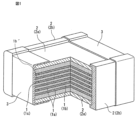
- FIG. 1 is a schematic diagram showing an example of a solid-state battery of the present invention, and is a combined perspective view and cross-sectional view.
- FIG. 2 is a schematic perspective view showing another example of a solid-state battery of the present invention.
- FIG. 2 shows an enlarged schematic diagram of an oxide ceramic for illustrating sintered particles constituting an example of the oxide ceramic contained in the exterior portion and/or insulating portion of the solid-state battery of the present invention, and the structure of the oxide ceramic.
- 1 shows an SEM photograph of the surface of the sintered body (exterior ceramic veneer) obtained in Example 1.
- 1 shows an SEM photograph of the surface of the sintered body (exterior ceramic veneer) obtained in Comparative Example 1.
- Example 1 shows a TEM photograph of the sintered body (exterior ceramic single plate) obtained in Example 1.
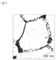
- 7 is an EDX mapping image showing the distribution of Bi elements in the TEM photograph shown in FIG. 6. The results of EDX quantitative analysis of the portion indicated by the arrow in the TEM photograph shown in FIG. 6 are shown.
- 1 shows an SEM photograph of a cross section of a sintered body (exterior ceramic single plate) obtained in Example 2.
- Solid-state battery refers to a battery whose components (particularly the electrolyte layer) are made of solids in a broad sense, and to an "all-solid-state battery” whose components (particularly all components) are made of solids in a narrow sense.
- the solid-state battery of the present invention is a laminated solid-state battery in which each layer constituting a battery unit is laminated on top of each other, and preferably each such layer is made of a sintered body.
- solid-state battery includes so-called “secondary batteries” that can be repeatedly charged and discharged, and “primary batteries” that can only be discharged.
- the "solid-state battery” is a "secondary battery".
- secondary battery is not excessively limited by its name, and may also include, for example, electrochemical devices such as “electricity storage devices”.
- solid electrolyte refers to one that does not include gel-like or liquid electrolytes (liquids).
- planar view in this specification refers to the state when the object is viewed from above or below along the thickness direction based on the stacking direction of the layers that make up the solid-state battery (described later) (top view or bottom view).
- cross-sectional view in this specification refers to the cross-sectional state (cross-sectional view) when viewed from a direction approximately perpendicular to the thickness direction based on the stacking direction L of the layers that make up the solid-state battery (described later).
- side view refers to the state when the solid-state battery is placed and viewed from the side in the thickness (height) direction, and is the same as a side view.
- the placement is such that the surface (flat surface) with the largest area that constitutes the appearance of the solid-state battery is the bottom surface.
- the "upper-lower direction” and “left-right direction” used directly or indirectly in this specification correspond to the upper-lower direction and left-right direction in the figure, respectively.
- the same reference numerals or symbols indicate the same members/parts or the same meanings.
- the vertical downward direction i.e., the direction in which gravity acts
- the opposite direction corresponds to the "upward direction”.
- the solid-state battery of the present invention may have any shape in plan view, and typically has a rectangular shape. Rectangular shapes include squares and rectangles.
- the solid-state battery of the present invention has a layered structure (particularly a laminated structure), for example, as shown in FIG. 1.
- the solid-state battery of the present invention has a battery element 1 and an exterior part 2 covering the surface of the battery element 1, and usually further has an external electrode 3 for drawing out the power (particularly the current) generated in the battery element to the outside.
- the insulating part is disposed between the electrode layer (positive electrode layer or negative electrode layer) 1a and the external electrode (negative electrode side or positive electrode side external electrode, respectively) 3, and is a member represented by "1c" in FIG. 1.
- FIG. 1 is a schematic cross-sectional view showing an example of a solid-state battery of the present invention.
- At least one of the exterior and insulating parts contains a specific oxide ceramic.
- the exterior and insulating parts only the exterior may contain a specific oxide ceramic, only the insulating part may contain a specific oxide ceramic, or both may contain a specific oxide ceramic.
- at least the exterior contains a specific oxide ceramic, and more preferably both the exterior and insulating parts contain a specific oxide ceramic.
- the solid-state battery of the present invention will be described in detail below using a first embodiment and a second embodiment. The present invention includes the first embodiment and the second embodiment.
- the exterior part contains a specific oxide ceramic out of the exterior part and the insulating part.
- the insulating part may or may not contain the specific oxide ceramic.
- both the exterior part and the insulating part contain the specific oxide ceramic from the viewpoint of further improving low-temperature densification characteristics, moisture resistance, and reactivity resistance.
- the exterior part 2 is a member covering the outside of the battery element 1, and has the function of covering the battery element 1 to prevent moisture from entering the battery element 1.
- the exterior part 2 usually has not only such a function but also a function of electrically, physically and chemically protecting the battery element, so it can also be called a protective layer or protective film.
- the exterior part 2 includes a main surface exterior part 2a (e.g., a set of main surface exterior parts 2a) covering the main surface of the battery element 1 and a side surface exterior part 2b (e.g., a set of side surface exterior parts 2b) covering the side surface of the battery element 1.
- the exterior part 2 usually has a layer form or a film form.
- the exterior part 2 may be in direct contact with the surface (particularly the main surface and/or side surface) of the battery element 1, or may be indirectly in contact with the surface via another layer (or film). From the viewpoint of more fully exerting the effects of the present invention, it is preferable that the exterior part 2 is in direct contact with the surface (particularly the main surface and/or side surface) of the battery element 1.
- the exterior portion 2 contains a specific oxide ceramic.
- low-temperature densification properties refer to the property of forming an exterior part (and/or an insulating part) with a sufficiently reduced areal porosity even at a relatively low temperature (e.g., 1000°C or less (particularly 800°C or less)).
- Moisture resistance refers to a property that prevents the intrusion of moisture, and may be a property (for example, water vapor barrier property) that sufficiently reduces the water vapor transmission rate (WVTR) even under high temperature and high humidity conditions.
- anti-reactivity refers to a property in which the exterior part (and/or insulating part) (particularly the oxide ceramic contained in the exterior part (and/or insulating part)) is unlikely to react (e.g., undergo a side reaction) with the solid electrolyte contained in the battery element even when fired (e.g., fired at 800°C for 5 hours).
- the anti-reactivity may particularly refer to a property in which the oxide ceramic and the solid electrolyte are unlikely to react with each other even when fired together.
- the oxide ceramics contained in the exterior portion contain Li (lithium); Mg (magnesium); one or more elements (M) selected from the group consisting of elements of groups 4 and 5; and Bi (bismuth).
- element M is one or more elements selected from the group consisting of Ti (titanium), Zr (zirconium), Hf (hafnium), Ta (tantalum), and Nb (niobium).
- element M is preferably at least one element selected from Ti, Ta, and Nb, or two elements, Zr and Ta.
- the oxide ceramics containing a combination of Li, Mg, element M, and Bi an exterior portion having excellent low-temperature densification characteristics and moisture resistance can be obtained. If the oxide ceramics does not contain one or more elements of Li, Mg, element M, and Bi, the low-temperature densification characteristics are reduced, and as a result, the moisture resistance is also reduced.
- the molar ratio Bi/(Mg+M) is not particularly limited, but from the viewpoint of further improving the low-temperature densification characteristics, moisture resistance, and reactivity resistance, it is preferably within the following range.
- ⁇ Bi/(Mg+M) Preferably, 0 ⁇ Bi/(Mg+M) ⁇ 0.100; More preferably, 0.001 ⁇ Bi/(Mg+M) ⁇ 0.080; More preferably, 0.004 ⁇ Bi/(Mg+M) ⁇ 0.060; Sufficiently preferably 0.005 ⁇ Bi/(Mg+M) ⁇ 0.040.
- the molar ratios Li/M and Mg/M are not particularly limited, but from the viewpoint of further improving the low-temperature densification characteristics, moisture resistance, and reactivity resistance, they are preferably within the following ranges.
- ⁇ Li/M Preferably, 0 ⁇ Li/M ⁇ 5; More preferably, 1.0 ⁇ Li/M ⁇ 4.0; More preferably, 1.5 ⁇ Li/M ⁇ 3.5; Quite preferably 1.9 ⁇ Li/M ⁇ 3.0.
- Mg/M Preferably, 0 ⁇ Mg/M ⁇ 9.8; More preferably, 0.01 ⁇ Mg/M ⁇ 7.0; More preferably, 0.05 ⁇ Mg/M ⁇ 6.0; Enough preferably 0.08 ⁇ Mg/M ⁇ 4.2.
- the Bi/(Mg+M), Li/M and Mg/M in oxide ceramics are values calculated from the contents (or molar ratios) of Li, Mg, M and Bi measured using a method similar to the analytical method for the chemical composition of oxide ceramics described below.
- the Mg content in the oxide ceramic is usually 0% by mass or more and 58% by mass or less, particularly 1.9% by mass or more and 46% by mass or less, based on the total amount of the oxide ceramic.
- the Mg content is measured by optical emission spectroscopy using high-frequency inductively coupled plasma (ICP) as a light source.
- ICP-AES ICP optical emission spectroscopy
- LA-ICP-MS laser ablation ICP mass spectrometry
- ICP-AES and LA-ICP-MS differ in that metal ions such as Mg are ionized by either dissolving them in solution or by using laser ablation, but are the same in that these ions are introduced into a plasma and excited by the plasma.
- LA-ICP-MS is useful for simple measurements when analyzing from a solid state.
- quantitative analysis composition analysis
- the oxide ceramics may have any chemical composition as long as it has the above molar ratio. From the viewpoint of further improving low-temperature densification characteristics, moisture resistance, and reactivity resistance, it is preferable that the oxide ceramics have a chemical composition represented by the following general formula (1).
- A is one or more elements selected from the group consisting of Na, K, Rb, Ca, Sr, Ba, Sc, Y, Mo, W, Zn, Al, Ga, Ge, Sn, and Sb.
- M is one or more elements selected from the same group as the above-mentioned element M, and from the viewpoint of further improving low-temperature densification characteristics, moisture resistance, and reactivity resistance, it preferably contains one or more elements selected from the group consisting of Ti, Zr, Nb, and Ta, more preferably contains at least one element selected from Ti, Ta, and Nb, or two elements selected from Zr and Ta, and further preferably contains only Ti.
- ⁇ 1/ ⁇ satisfies the same range as the molar ratio Li/M described above, and from the viewpoint of further improving low-temperature densification characteristics, moisture resistance, and reactivity resistance, preferably satisfies the preferred range of Li/M, more preferably satisfies the more preferred range of Li/M, even more preferably satisfies the more preferred range of Li/M, and sufficiently preferably satisfies the sufficiently preferred range of Li/M.
- ⁇ / ⁇ satisfies the same range as the molar ratio Mg/M described above, and from the viewpoint of further improving low-temperature densification characteristics, moisture resistance, and reactivity resistance, preferably satisfies the preferred range of Mg/M, more preferably satisfies the more preferred range of Mg/M, even more preferably satisfies the more preferred range of Mg/M, and sufficiently preferably satisfies the sufficiently preferred range of Mg/M.
- the average valence of M is a value expressed by (n1 ⁇ a+n2 ⁇ b+n3 ⁇ c)/(n1+n2+n3) when M contains, for example, n1 element X with a valence a+, n2 element Y with a valence b+, and n3 element Z with a valence c+.
- a is the average valence of A.
- the average valence of A is, for example, a value expressed by (n1 ⁇ a+n2 ⁇ b+n3 ⁇ c)/(n1+n2+n3) when A contains n1 element X with a valence of a+, n2 element Y with a valence of b+, and n3 element Z with a valence of c+.
- b is the average valence of Bi, and generally has a value of 3 ⁇ b ⁇ 5.
- Bi is usually present in the grain boundary (second phase), main phase (first phase), or both phases of oxide ceramics, as described later.
- the grain boundary occurring between adjacent main phases can be called the "second phase”.
- the valence of Bi changes depending on the form (or location) of existence of such Bi.
- the valence of Bi when Bi is present in the grain boundary, the valence of Bi is often "3".
- the valence of Bi is often "5". Therefore, the average valence of Bi is a value expressed by (n1 ⁇ 3+n2 ⁇ 5)/(n1+n2) when, for example, n1 pieces of Bi are found in the grain boundary with a valence of 3 and n2 pieces are found in the main phase with a valence of 5.
- the oxygen number ⁇ may deviate from the above value by about ⁇ 10%. In other words, some oxygen vacancies or interstitial oxygen may be included.
- ⁇ 1 usually satisfies 0 ⁇ 1 ⁇ 1.0, and from the viewpoint of further improving low-temperature densification characteristics, moisture resistance, and reactivity resistance, preferably satisfies 0.10 ⁇ 1 ⁇ 0.80, and more preferably satisfies 0.20 ⁇ 1 ⁇ 0.70.
- ⁇ 2 usually satisfies 0 ⁇ 2 ⁇ 1.0, and from the viewpoint of further improving the low-temperature densification characteristics, moisture resistance, and reactivity resistance, preferably satisfies 0 ⁇ 2 ⁇ 0.5, more preferably satisfies 0 ⁇ 2 ⁇ 0.1, and further preferably is 0.
- ⁇ usually satisfies 0 ⁇ 1.0, and from the viewpoint of further improving low-temperature densification characteristics, moisture resistance, and reactivity resistance, preferably satisfies 0.01 ⁇ 0.80, and more preferably satisfies 0.01 ⁇ 0.60.
- ⁇ usually satisfies 0 ⁇ 1.0, and from the viewpoint of further improving low-temperature densification characteristics, moisture resistance, and reactivity resistance, preferably satisfies 0.05 ⁇ 0.50, and more preferably satisfies 0.10 ⁇ 0.40.
- x usually satisfies 0 ⁇ x ⁇ 1.0, and from the viewpoint of further improving the low-temperature densification characteristics, moisture resistance, and reactivity resistance, preferably satisfies 0.001 ⁇ x ⁇ 0.050, and more preferably satisfies 0.002 ⁇ x ⁇ 0.030.
- the chemical composition of oxide ceramics can be determined by ICP analysis (inductively coupled plasma method) or LA-ICP-MS (laser ablation ICP mass spectrometry) analysis.
- EDX energy dispersive X-ray spectroscopy
- WDX wavelength dispersive X-ray spectroscopy
- the chemical composition may be obtained by performing quantitative analysis (composition analysis) of any 100 points on each of any 100 sintered particles and calculating the average value.
- oxide ceramics are usually composed of a main phase (i.e., a first phase) 21 of a plurality of sintered particles and a grain boundary (i.e., a second phase) 22 arranged between two adjacent main phases 21.
- the main phase 21 includes a grain boundary vicinity 23 close to the grain boundary 22 and an interior 24 arranged inside the grain boundary vicinity 23.
- the grain boundary vicinity 23 is a region (i.e., a grain boundary vicinity region from the boundary 20 to the dashed line in FIG. 3) that is a distance from the boundary 20 to the grain boundary 22 (i.e., a distance from the grain boundary boundary 20 toward the interior 24) of 50 nm or less.
- the grain boundary 22 is a region between two adjacent main phases 21.
- the grain boundary 22 does not necessarily have to have a phase (especially a second phase).
- FIG. 3 shows an enlarged schematic diagram of sintered particles constituting an example of an oxide ceramic contained in the exterior part (and/or insulating part) of the solid-state battery of the present invention, and an oxide ceramic for explaining its structure.
- FIG. 3 only three main phases 21 of sintered grains are shown, but usually many sintered grains exist around them, forming grain boundaries between adjacent sintered grains.
- Bi is preferably contained in the oxide ceramic in a form present at least in the grain boundaries (second phase) (for example, the above-mentioned existence form (x1) or (x3) (particularly the existence form (x3))).
- Bi is concentrated at the grain boundaries and/or in the vicinity of the grain boundaries of the oxide ceramic. Concentrated means that the concentration is higher.
- the concentration of Bi in the grain boundaries 22 and/or in the vicinity of the grain boundaries 23 of the oxide ceramic is higher than the concentration of Bi in the interior 24 located inside the vicinity of the grain boundaries 23.
- the presence/absence of Bi in the grain boundaries (second phase) and main phase (first phase) of such oxide ceramics can be determined based on the distribution of Bi elements in EDX mapping (300,000 to 2,000,000 times magnification) by TEM-EDX observation, as shown in Fig. 7, which will be described later. It is clear from Fig. 7 that Bi is concentrated at the grain boundaries (or grain boundaries and areas near grain boundaries) of the oxide ceramics. For example, when Bi is detected at grain boundaries in the distribution of Bi element, the presence of Bi is recognized, whereas when Bi is not detected at grain boundaries in the distribution of Bi element, the absence of Bi is recognized. For example, when Bi is detected in the main phase in the distribution of Bi element, the presence of Bi is recognized.
- ⁇ TEM-EDX TEM equipment JEOL JEM-F200 EDX detector: EX-24390UBN5T EDX system: Noran system 7 Measurement conditions: Using a sample that has been exfoliated to a thickness of 100 nm or less, EDX is performed at an accelerating voltage of 200 kV, and Bi is detected when measured under conditions where the Mg K ⁇ count is 550,000 or more in the field of view of 666 nm.
- the grain boundary (second phase) 22 is mainly composed of the sintering aid. Also, for example, if the exterior portion is composed of oxide ceramics and does not contain a sintering aid, the grain boundary (second phase) 22 is composed of components leached out from the oxide ceramics. In either of these cases, from the viewpoint of further improving the low-temperature densification characteristics, moisture resistance, and reactivity resistance, it is preferable that the grain boundary (second phase) 22 is composed of at least one element selected from the group consisting of Li, Mg, and M in addition to Bi.
- the crystal structure of the oxide ceramics is not particularly limited, and may be, for example, a rock salt crystal structure, a spinel crystal structure, a layered rock salt crystal structure, or a mixed phase structure of these. From the viewpoint of further improving low-temperature densification characteristics, moisture resistance, and reactivity resistance, the oxide ceramics preferably has a rock salt crystal structure or a layered rock salt crystal structure (particularly only a rock salt crystal structure or a layered rock salt crystal structure), and more preferably has a rock salt crystal structure. Note that the crystal structure may refer to the crystal structure of the main phase.
- the crystal structure can be detected using the following analytical equipment and conditions. ⁇ X-ray diffraction analyzer; Bruker D2 PHASER; Analytical conditions: Cu K ⁇ , 2 ⁇ : 10-60°, step width 0.02°/sec.
- an oxide ceramic has only a rock salt crystal structure
- the main phase (particularly the inside 24) of the oxide ceramic has only a rock salt crystal structure, and does not substantially contain any crystal structure other than the rock salt crystal structure.
- the main phase has only a rock salt crystal structure
- the crystal structure of the oxide ceramic is analyzed using the above-mentioned analysis device and analysis conditions, only the rock salt crystal structure and the crystal structure of the second phase are detected, and no crystal structure other than these crystal structures is detected.
- crystal structures other than these crystal structures may be contained in an amount below the detection limit value by analysis using the device and conditions. In this case, the crystal structure of the second phase may or may not be detected.
- an oxide ceramic has only a layered rock-salt type crystal structure
- the main phase (particularly the inside 24) of the oxide ceramic has only a layered rock-salt type crystal structure, and does not substantially contain any crystal structure other than the layered rock-salt type crystal structure.
- the main phase has only a layered rock-salt type crystal structure
- the crystal structure of the oxide ceramic is analyzed using the above-mentioned analysis device and analysis conditions, only the layered rock-salt type crystal structure and the crystal structure of the second phase are detected, and no crystal structure other than these crystal structures is detected.
- crystal structures other than these crystal structures may be contained in an amount below the detection limit value by analysis using the device and conditions. In this case, the crystal structure of the second phase may or may not be detected.
- oxide ceramics having a rock-salt type crystal structure does not simply mean that the oxide ceramics have a "rock-salt type crystal structure", but also includes the meaning of "rock-salt type-like crystal structure”.
- the oxide ceramics have a crystal structure that can be recognized as a rock-salt type or rock-salt type-like crystal structure by a person skilled in the field of solid-state batteries in X-ray diffraction. More specifically, the oxide ceramics may show one or more main peaks corresponding to Miller indices specific to the so-called rock-salt type crystal structure diffraction pattern: ICDD Card No.
- 00-004-0829 at a predetermined incidence angle in X-ray diffraction may show one or more main peaks with different incidence angles (i.e., peak positions or diffraction angles) and intensity ratios (i.e., peak intensities or diffraction intensity ratios) due to differences in composition from one or more main peaks corresponding to Miller indices specific to the so-called rock-salt type crystal structure as a rock-salt type-like crystal structure.
- Representative diffraction patterns of rock-salt type-like crystal structures include, for example, ICDD Card No. Examples include 00-036-0308.
- the oxide ceramic having a spinel crystal structure does not only mean that the oxide ceramic has a "spinel crystal structure", but also means that the oxide ceramic has a "spinel-like crystal structure".
- the oxide ceramic has a crystal structure that can be recognized as a spinel or spinel-like crystal structure by a person skilled in the field of solid-state batteries in X-ray diffraction. More specifically, the oxide ceramic may show one or more main peaks corresponding to Miller indices specific to the so-called spinel crystal structure diffraction pattern: ICDD Card No.
- 01-072-6998 at a predetermined incidence angle in X-ray diffraction may show one or more main peaks with different incidence angles (i.e., peak positions or diffraction angles) and intensity ratios (i.e., peak intensities or diffraction intensity ratios) due to differences in composition from one or more main peaks corresponding to Miller indices specific to the so-called spinel crystal structure as a spinel-like crystal structure.
- the oxide ceramic has a mixed phase structure of a rock salt type crystal structure and a spinel type crystal structure, which means that the oxide ceramic contains oxide ceramics having both the above-mentioned rock salt type crystal structure and spinel type crystal structure.
- the oxide ceramics having a layered rock-salt type crystal structure does not only mean that the oxide ceramics have a "layered rock-salt type crystal structure," but also means that the oxide ceramics have a "layered rock-salt type-like crystal structure.”
- the oxide ceramics have a crystal structure that can be recognized as a layered rock-salt type or a layered rock-salt type-like crystal structure by a person skilled in the field of solid-state batteries in X-ray diffraction. More specifically, the oxide ceramics may show one or more main peaks corresponding to Miller indices specific to the so-called layered rock-salt type crystal structure diffraction pattern: ICDD Card No.
- 00-033-0831 at a predetermined angle of incidence in X-ray diffraction, or may show one or more main peaks that have different angles of incidence (i.e., peak positions or diffraction angles) and intensity ratios (i.e., peak intensities or diffraction intensity ratios) due to differences in composition from one or more main peaks corresponding to Miller indices specific to the so-called layered rock-salt type crystal structure, as a layered rock-salt type-like crystal structure.
- a typical diffraction pattern of a crystal structure similar to layered rock salt type is, for example, ICDD Card No. 00-033-0843.
- the oxide ceramics may be produced by any method that can obtain an oxide ceramics having a desired composition, and examples of the method include the following methods (1) and (2).
- Method (1) First, raw materials including a Li source, an Mg source, and an element M source are weighed out so that a predetermined element has a desired composition (molar ratio), and then thoroughly mixed with water and fired (first firing step). Next, the obtained fired product is weighed out together with a Bi-containing firing aid as a Bi source so that a predetermined element has a desired composition (molar ratio), and thoroughly mixed with alcohol and a binder. Thereafter, the obtained slurry is formed into a sheet shape and fired to obtain an oxide ceramic that constitutes the exterior part (second firing step).
- the Bi-containing firing aid is preferably an oxide containing Bi, and more preferably an oxide containing Bi and Li. Specific examples of the Bi - containing firing aid include LiBiO2 and Li3BiO3 .
- Oxide ceramics can be obtained by weighing out raw materials including a Li source, an Mg source, an element M source, and a Bi source so that the desired composition (molar ratio) of the specified elements is achieved, thoroughly mixing the mixture with water, and then firing the mixture (firing process).
- the firing temperature in the first firing step in method (1) and the firing step in method (2) is not particularly limited, and may be, for example, 800° C. to 1200° C. (particularly, 850° C. to 1100° C.).
- the firing time is not particularly limited, and may be, for example, 1 hour to 10 hours (particularly, 3 hours to 7 hours).
- the firing temperature and firing time in the second firing step in the method (1) are the same as those in the "firing step" in the "production method of a solid-state battery" described later.
- the Li source for example, lithium carbonate (Li 2 CO 3 ) can be used.
- Mg source for example, magnesium oxide (MgO) can be used.
- element M source for example, titanium oxide (TiO 2 ), niobium oxide (Nb 2 O 5 ), zirconium oxide (ZrO 2 ), tantalum oxide (Ta 2 O 5 ), and hafnium oxide (HfO 2 ) can be used.
- the Bi source for example, Bi 2 O 3 can be used. In the production of oxide ceramics, the ratio of the Li source, Mg source, and element M source at the time of charging is almost the same as the final composition of the obtained oxide ceramics.
- the above-mentioned molar ratios x/( ⁇ + ⁇ ), Li/M ( ⁇ 1/ ⁇ ), and Mg/M ( ⁇ / ⁇ ) can be controlled.
- This embodiment does not preclude the exterior part 2 from containing other oxide ceramics in addition to the specific oxide ceramics described above.
- other oxide ceramics include Li-Bi-O-based oxides, Li-Mg-Bi-O-based oxides, Bi 2 O 3 , Mg-Bi-O-based oxides, Li-M-O-based oxides (wherein M is the same as M in the formula (1)), Li-Bi-M-O-based oxides (wherein M is the same as M in the formula (1)), MgO, and the like.
- the content of the specific oxide ceramics in the exterior part 2 may usually be an area ratio of 60% or more and 100% or less, particularly an area ratio of 90% or more and 100% or less. The area ratio can be measured as follows.
- the solid-state battery is broken so that the fracture surface of the ceramics of the exterior part is exposed.
- the fracture surface is polished using a cross-section polisher or the like to obtain a polished surface.
- EDX analysis is performed on any surface, and the region where Mg, element M, and element A are detected and Li is detected by TOF-SIMS is regarded as the above-mentioned specific oxide ceramic region. From the above, the area ratio of the oxide ceramic to the area of the exterior part can be calculated and measured.
- the exterior part 2 may or may not contain a sintering aid.
- sintering aids that may be contained in the exterior part include the Bi-containing sintering aid described above, and sintering aids that may be contained in the positive electrode layer and negative electrode layer described below. From the viewpoint of further improving low-temperature densification characteristics, moisture resistance, and reactivity resistance, it is preferable that the exterior part 2 does not contain any sintering aids other than the Bi-containing sintering aid.
- the exterior part 2 usually has a thickness of preferably 1 ⁇ m or more and 500 ⁇ m or less, more preferably 5 ⁇ m or more and 100 ⁇ m or less, and even more preferably 5 ⁇ m or more and 50 ⁇ m or less.
- the thickness of the exterior part 2 is the average thickness of thicknesses at any 100 points.
- the relative density of the exterior part 2 is usually 90% or more and 100% or less, and preferably 95% or more and 100% or less.
- the relative density of the exterior part may be measured using the Archimedes method.
- the exterior part 2 is usually insulating. Insulating refers to a property of having neither ionic conductivity nor electronic conductivity.
- the ionic conductivity of the exterior part 2 is usually 1 ⁇ 10 ⁇ 7 S/cm or less, and in particular, the ionic conductivity is 1 ⁇ 10 ⁇ 10 S/cm or less.
- the ionic conductivity of the exterior part 2 is usually 1 ⁇ 10 ⁇ 18 S/cm or more.
- the electronic conductivity of the exterior part 2 is usually 1 ⁇ 10 ⁇ 7 S/cm or less, and in particular, 1 ⁇ 10 ⁇ 10 S/cm or less.
- the electronic conductivity of the exterior part 2 is usually 1 ⁇ 10 ⁇ 18 S/cm or more.
- the oxygen permeability of the exterior part 2 in the thickness direction may be, for example, 10 ⁇ 1 cc/m 2 /day/atmosphere or less, particularly 10 ⁇ 3 cc/m 2 /day/atmosphere or less.
- the H 2 O permeability in the thickness direction of the exterior part 2 may be, for example, 10 ⁇ 2 g/m 2 /day or less, particularly 10 ⁇ 4 g/m 2 /day or less.
- the H 2 O permeability is measured at 25° C. by the cup method, the carrier gas method, the pressure method, or the Ca corrosion method.
- FIG. 1 is a schematic perspective view showing another example of the solid-state battery of the present invention.
- the solid-state battery of FIG. 2 is similar to the solid-state battery of FIG. 1 except that the main surface exterior part 2a and the side surface exterior part 2b have an integrated form.
- the main surface exterior part 2a and the side surface exterior part 2b can be manufactured using a method (green sheet method) of attaching a sheet to be described later.
- the manufacture of the solid-state battery (particularly the exterior part 2) becomes significantly simpler.
- the oxide ceramic contained in the main surface exterior part 2a usually has the same chemical composition as the oxide ceramic contained in the side surface exterior part 2b.
- the exterior part 2 is an integral sintered body formed of a sintered body with the surface of the battery element 1 (particularly the main surface and/or side surface).
- the exterior part 2 is an integral sintered body formed of a sintered body with the surface of the battery element 1 means that the exterior part 2 and the battery element 1 are joined by sintering. More specifically, the exterior part 2 and the battery element 1 are both sintered bodies, but are sintered together. Note that the exterior part 2 and the battery element 1 do not necessarily have to be strictly entirely integrated, and it is not necessary that only a portion of them are integrated. It is sufficient that the exterior part 2 and the battery element 1 are integrated as a whole.
- the battery element 1 is a main body of a solid-state battery covered by an exterior part 2, and includes one or more battery units.
- the battery unit means the smallest unit capable of performing the battery function, and includes a set of electrode layers 1a (specifically, one positive electrode layer and one negative electrode layer facing each other) and one solid electrolyte layer 1b disposed between the set of electrode layers 1a (i.e., between the positive electrode layer and the negative electrode layer).
- the battery element 1 may have a single cell structure having only one battery unit, or may have a bi-cell structure in which two or more battery units are stacked along the stacking direction of each layer constituting each battery unit.
- the electrode layers include a positive electrode layer and a negative electrode layer.
- the battery element 1 usually has an insulating part 1c for ensuring electrical non-contact between one electrode layer and an external electrode for drawing current from the other electrode layer to the outside.
- the battery element 1 is disposed between the positive electrode layer and an external electrode (i.e., a negative electrode-side external electrode) for drawing current from the negative electrode layer to the outside, and has an insulating part 1c for ensuring electrical non-contact therebetween.
- the battery element 1 is disposed between the negative electrode layer and an external electrode (i.e., a positive electrode-side external electrode) for drawing current from the positive electrode layer to the outside, and has an insulating part 1c for ensuring electrical non-contact therebetween.
- the battery element usually has solid electrolyte layers 1b in the uppermost and lowermost layers of the battery element, as shown in FIG. 1.
- the insulating portion may or may not contain the specific oxide ceramics described above.
- both the exterior portion and the insulating portion contain the specific oxide ceramics.
- the description of the insulating part may be applied by replacing "exterior part" with “insulating part” unless otherwise specified. Therefore, the oxide ceramic contained in the insulating part may be selected from within the same range as the oxide ceramic contained in the exterior part described above.
- the specific oxide ceramic contained in the insulating part and the specific oxide ceramic contained in the exterior part may each be selected independently.
- the preferred oxide ceramic contained in the insulating part may be selected from within the same range as the preferred oxide ceramic contained in the exterior part described above.
- the insulating portion usually has a thickness similar to that of the positive electrode layer or the negative electrode layer.
- the thickness of the insulating portion is preferably 1 ⁇ m or more and 500 ⁇ m or less, more preferably 5 ⁇ m or more and 100 ⁇ m or less, and even more preferably 5 ⁇ m or more and 50 ⁇ m or less.
- the thickness of the insulating portion is the average thickness of thicknesses at any 100 points.
- the relative density of the insulating part is usually 90% or more and 100% or less, and preferably 95% or more and 100% or less.
- the relative density of the insulating part may be measured using the Archimedes method.
- the insulating portion has insulation and has neither ionic conductivity nor electronic conductivity.
- the ionic conductivity of the insulating portion is usually 1 ⁇ 10 ⁇ 7 S/cm or less, particularly 1 ⁇ 10 ⁇ 10 S/cm or less.
- the ionic conductivity of the insulating portion is usually 1 ⁇ 10 ⁇ 18 S/cm or more.
- the electronic conductivity of the insulating portion is usually 1 ⁇ 10 ⁇ 7 S/cm or less, particularly 1 ⁇ 10 ⁇ 10 S/cm or less.
- the electronic conductivity of the insulating portion is usually 1 ⁇ 10 ⁇ 18 S/cm or more.
- the oxygen permeability of the insulating portion in the thickness direction may be, for example, 10 ⁇ 1 cc/m 2 /day/atmosphere or less, particularly 10 ⁇ 3 cc/m 2 /day/atmosphere or less.
- the H 2 O permeability in the thickness direction of the insulating part may be, for example, 10 ⁇ 2 g/m 2 /day or less, particularly 10 ⁇ 4 g/m 2 /day or less.
- the H 2 O permeability is measured at 25° C. by the cup method, carrier gas method, pressure method, or Ca corrosion method.
- the insulating part may be composed of any oxide ceramics known in the field of solid-state batteries.
- the insulating part may be the same as the insulating part described above, except that it is composed of the same oxide ceramics as the "other oxide ceramics" described in the explanation of the exterior part.
- the insulating portion includes an insulating portion disposed between the positive electrode layer and the negative electrode side external electrode, and an insulating portion disposed between the negative electrode layer and the positive electrode side external electrode.
- the insulating portion usually has a layer form or a film form.
- the insulating portion is disposed between the two solid electrolyte layers, and may be in direct contact with the surface (particularly a part of the main surface) of each of the two solid electrolyte layers, or may be in indirect contact via another layer (or film).
- the insulating portion is disposed between the two solid electrolyte layers, and is in direct contact with the surface (particularly a part of the main surface) of each of the two solid electrolyte layers.
- the insulating part is disposed between two solid electrolyte layers and is in direct contact with the surfaces (particularly parts of the main surfaces) of the two solid electrolyte layers, it is preferable that the insulating part is an integral sintered body of the sintered bodies of the surfaces (particularly parts of the main surfaces) of the two solid electrolyte layers.
- the insulating part being an integral sintered body of the sintered bodies of the surfaces of the two solid electrolyte layers means that the insulating part and the two solid electrolyte layers are joined by sintering. More specifically, the insulating part and the two solid electrolyte layers are both sintered bodies, but are sintered together.
- the insulating part and the two solid electrolyte layers do not necessarily have to be strictly integrated in their entirety, and it is not necessary that only a portion of them is integrated. It is sufficient that the insulating part and the two solid electrolyte layers are integrated as a whole.
- the battery element usually contains a solid electrolyte (hereinafter, sometimes referred to as the first solid electrolyte).
- the first solid electrolyte contained in the battery element may have any crystal structure, for example, a garnet-type crystal structure, a LISICON-type crystal structure, a perovskite-type crystal structure, or a mixed phase structure thereof.
- the first solid electrolyte contained in the battery element preferably has a garnet-type crystal structure, a LISICON-type crystal structure, or a mixed phase structure thereof, and more preferably has a garnet-type crystal structure.
- the reactivity with the oxide ceramic of the exterior increases in the order of a solid electrolyte having a perovskite-type crystal structure, a solid electrolyte having a LISICON-type crystal structure, and a solid electrolyte having a garnet-type crystal structure, but even if the battery element contains such a solid electrolyte, the oxide ceramic of the exterior can more sufficiently suppress the reaction with the solid electrolyte.
- the first solid electrolyte may be included in one or more layers selected from the positive electrode layer, the negative electrode layer, and the solid electrolyte layer. From the viewpoint of further improving low-temperature densification characteristics, moisture resistance, and reactivity resistance, it is preferable that such a first solid electrolyte is included in at least the solid electrolyte layer.
- a solid electrolyte having a garnet-type crystal structure does not simply mean that the solid electrolyte has a "garnet-type crystal structure", but also means that the solid electrolyte has a "garnet-type-like crystal structure”.
- the solid electrolyte has a crystal structure that can be recognized as a garnet-type or garnet-type-like crystal structure by a person skilled in the field of solid-state batteries in X-ray diffraction. More specifically, the solid electrolyte may show one or more main peaks corresponding to Miller indices specific to the so-called garnet-type crystal structure diffraction pattern (ICDD Card No.
- garnet-type-like crystal structures include, for example, ICDD Card No. Examples include 00-045-0109.
- a solid electrolyte having a garnet-type crystal structure may have any chemical composition.
- a garnet-type solid electrolyte has a chemical composition represented by the following general formula (2).
- a 1 refers to a metal element occupying the Li site in the garnet-type crystal structure.
- a 1 is usually one or more elements selected from the group consisting of Ga (gallium), Al (aluminum), Mg (magnesium), Zn (zinc) and Sc (scandium).
- a 1 is preferably one or more elements selected from the group consisting of Ga (gallium) and Al (aluminum), more preferably two elements, Ga and Al, from the viewpoint of further improving low-temperature densification characteristics, moisture resistance and reactivity resistance.
- B1 refers to a metal element occupying the La site in the garnet-type crystal structure.
- B1 is usually one or more elements selected from the group consisting of Ca (calcium), Sr (strontium), Ba (barium), and lanthanoid elements.
- lanthanoid elements include Ce (cerium), Pr (praseodymium), Nd (neodymium), Pm (promethium), Sm (samarium), Eu (europium), Gd (gadolinium), Tb (terbium), Dy (dysprosium), Ho (holminium), Er (erbium), Tm (thulium), Yb (ytterbium), and Lu (lutetium).
- D 1 refers to a metal element occupying a hexacoordinated site in a garnet-type crystal structure.
- the hexacoordinated site in a garnet-type crystal structure is, for example, a site occupied by Nb in Li 5 La 3 Nb 2 O 12 (ICDD Card No. 00-045-0109) having a garnet-type crystal structure, or a site occupied by Zr in Li 7 La 3 Zr 2 O 12 (ICDD Card. No. 01-078-6708).
- D 1 represents one or more elements selected from the group consisting of transition elements capable of forming hexacoordinated positions with oxygen and typical elements belonging to groups 12 to 15.
- transition elements capable of forming 6-coordination with oxygen include Sc (scandium), Zr (zirconium), Ti (titanium), Ta (tantalum), Nb (niobium), Hf (hafnium), Mo (molybdenum), W (tungsten), and Te (tellurium).
- Examples of typical elements belonging to groups 12 to 15 include In (indium), Ge (germanium), Sn (tin), Pb (lead), Sb (antimony), and Bi (bismuth).
- D1 is usually one or more elements selected from the group consisting of Zr (zirconium), Sn (tin), Sb (antimony), Ti (titanium), Ta (tantalum), Nb (niobium), Hf (hafnium), Mo (molybdenum), W (tungsten) and Te (tellurium), and from the viewpoint of further improving low-temperature densification characteristics, moisture resistance and reactivity resistance, preferably contains one or more elements selected from the group consisting of Zr (zirconium), Ta (tantalum) and Nb (niobium), more preferably contains Zr (zirconium) and Ta (tantalum).
- x satisfies 0 ⁇ x ⁇ 1.00, and from the viewpoint of further improving low-temperature densification characteristics, moisture resistance, and reactivity resistance, preferably satisfies 0 ⁇ x ⁇ 0.70, more preferably 0 ⁇ x ⁇ 0.40, even more preferably 0 ⁇ x ⁇ 0.40, and particularly preferably 0 ⁇ x ⁇ 0.20.
- y satisfies 0 ⁇ y ⁇ 0.50, and from the viewpoint of further improving low-temperature densification characteristics, moisture resistance, and reactivity resistance, preferably satisfies 0 ⁇ y ⁇ 0.40, more preferably 0 ⁇ y ⁇ 0.30, and further preferably 0 ⁇ y ⁇ 0.20.
- ⁇ satisfies 2.5 ⁇ 3.5, and from the viewpoint of further improving low-temperature densification characteristics, moisture resistance, and reactivity resistance, ⁇ is preferably 2.7 ⁇ 3.3, more preferably 2.8 ⁇ 3.2, and even more preferably 2.9 ⁇ 3.1.
- z satisfies 0 ⁇ z ⁇ 2.00, and from the viewpoint of further improving the low-temperature densification characteristics, moisture resistance, and reactivity resistance, preferably satisfies 0 ⁇ z ⁇ 1.00, more preferably 0 ⁇ z ⁇ 0.50, and further preferably is 0.
- ⁇ satisfies 1.5 ⁇ 2.5, and from the viewpoint of further improving low-temperature densification characteristics, moisture resistance, and reactivity resistance, preferably satisfies 1.7 ⁇ 2.3, more preferably 1.8 ⁇ 2.2, and further preferably 1.9 ⁇ 2.0.
- p usually satisfies 6.0 ⁇ p ⁇ 7.0, and from the viewpoint of further improving the low-temperature densification characteristics, moisture resistance, and reactivity resistance, preferably satisfies 6.2 ⁇ p ⁇ 6.8, and more preferably 6.4 ⁇ p ⁇ 6.8.
- a is the average valence of A 1.
- the average valence of A 1 is, for example, a value represented by (n1 x a + n2 x b + n3 x c) / (n1 + n2 + n3) when A 1 contains n1 element X with a valence of a+, n2 element Y with a valence of b+, and n3 element Z with a valence of c+.
- b is the average valence of B 1.
- the average valence of B 1 is the same as the average valence of A 1 described above when, for example, B 1 contains n1 element X with a valence a+, n2 element Y with a valence b+, and n3 element Z with a valence c+.
- c is the average valence of D 1.
- the average valence of D 1 is the same as the average valence of A 1 described above when, for example, D 1 contains n1 element X with a valence a+, n2 element Y with a valence b+, and n3 element Z with a valence c+.
- ⁇ indicates the amount of oxygen vacancy, and may be 0.
- the amount of oxygen vacancy ⁇ cannot be quantitatively analyzed even with the latest equipment, so it may be considered to be 0.
- the molar ratio of each element in the chemical composition of the oxide ceramic of the present invention does not necessarily coincide with, for example, the molar ratio of each element in formula (2) and tends to deviate from that depending on the analytical method. However, as long as the composition deviation is not so great as to cause a change in the characteristics, the effects of the present invention can be achieved.
- the chemical composition of the oxide ceramic may be the composition of the entire ceramic material determined using ICP (inductively coupled plasma). It may also be measured and calculated using ICP-AES (inductively coupled plasma atomic emission spectroscopy) or LA-ICP-MS (laser ablation inductively coupled plasma mass spectrometry). The chemical composition may also be measured and calculated using XPS analysis, or may be determined using TEM-EDX (energy dispersive X-ray spectroscopy) and/or WDX (wavelength dispersive X-ray spectroscopy). Furthermore, the chemical composition may be obtained by performing quantitative analysis (composition analysis) of any 100 points on each of any 100 sintered particles and calculating the average value.
- ICP inductively coupled plasma
- LA-ICP-MS laser ablation inductively coupled plasma mass spectrometry
- the chemical composition may also be measured and calculated using XPS analysis, or may be determined using TEM-EDX (energy dispersive X-ray spectroscopy) and/or WDX (wavelength
- garnet -type solid electrolyte represented by the general formula ( 2 ) include Li6.6La3Zr1.6Ta0.4O12 , Li6.4Ga0.05Al0.15La3Zr2O12 , Li6.75La3Zr1.75Nb0.25O12 , and Li6.53La3Zr1.53Ta0.4Bi0.07O12 .
- the LISICON type crystal structure of the solid electrolyte includes ⁇ I structure, ⁇ II type structure, ⁇ II ' type structure, T1 type structure, T2 type structure, ⁇ II type structure, and ⁇ 0 type structure. That is, the LISICON type solid electrolyte may include one or more solid electrolytes having a ⁇ I structure, a ⁇ II type structure, a ⁇ II ' type structure, a T1 type structure, a T2 type structure, a ⁇ II type structure, a ⁇ 0 type structure, or a composite structure thereof. From the viewpoint of further improving low-temperature densification characteristics, moisture resistance, and reactivity resistance, the LISICON type structure of the solid electrolyte is preferably a ⁇ II type structure.
- a solid electrolyte having a ⁇ II type structure means that the solid electrolyte has a ⁇ II type crystal structure, and in a broad sense, means that the solid electrolyte has a crystal structure that can be recognized as a ⁇ II type crystal structure by a person skilled in the field of solid state batteries.
- a solid electrolyte having a ⁇ II type structure means that the solid electrolyte shows one or more main peaks corresponding to Miller indices specific to the so-called ⁇ II -Li 3 VO 4 type crystal structure at a predetermined incidence angle in X-ray diffraction.
- solid electrolyte having a ⁇ I type structure means that the solid electrolyte has a ⁇ I type crystal structure, and in a broad sense, means that the solid electrolyte has a crystal structure that can be recognized as a ⁇ I type crystal structure by a person skilled in the field of solid state batteries. In a narrow sense, the term “solid electrolyte having a ⁇ I type structure” means that the solid electrolyte shows one or more main peaks corresponding to Miller indices specific to the so-called ⁇ I -Li 3 VO 4 type crystal structure at a predetermined incidence angle in X-ray diffraction.
- solid electrolyte having a ⁇ II type structure means that the solid electrolyte has a ⁇ II type crystal structure, and in a broad sense, means that the solid electrolyte has a crystal structure that can be recognized as a ⁇ II type crystal structure by a person skilled in the field of solid state batteries. In a narrow sense, the term “solid electrolyte having a ⁇ II type structure” means that the solid electrolyte shows one or more main peaks corresponding to Miller indices specific to the so-called ⁇ II -Li 3 VO 4 type crystal structure at a predetermined incidence angle in X-ray diffraction.
- solid electrolyte has a ⁇ II '-type structure means that the solid electrolyte has a ⁇ II '-type crystal structure, and in a broad sense, means that the solid electrolyte has a crystal structure that can be recognized as a ⁇ II '-type crystal structure by a person skilled in the field of solid-state batteries.
- solid electrolyte has a ⁇ II '-type structure means that the solid electrolyte shows one or more main peaks corresponding to Miller indices specific to the so-called ⁇ II '-Li 3 VO 4- type crystal structure at a predetermined incidence angle in X-ray diffraction.
- solid electrolyte having a T I type structure means that the solid electrolyte has a T I type crystal structure, and in a broad sense, means that the solid electrolyte has a crystal structure that can be recognized as a T I type crystal structure by a person skilled in the field of solid-state batteries.
- solid electrolyte having a T I type structure means that the solid electrolyte shows one or more main peaks corresponding to Miller indices specific to the so-called T I -Li 3 VO 4 type crystal structure at a predetermined incidence angle in X-ray diffraction.
- Compounds having a T I type structure i.e., solid electrolytes
- J. solid state chem AR West et.al, J. solid state chem., 4, 20-28 (1972)
- an example thereof is, for example, ICDD Card No. 00-024-0668.
- solid electrolyte having a T II type structure means that the solid electrolyte has a T II type crystal structure, and in a broad sense, means that the solid electrolyte has a crystal structure that can be recognized as a T II type crystal structure by a person skilled in the field of solid state batteries.
- solid electrolyte having a T II type structure means that the solid electrolyte shows one or more main peaks corresponding to Miller indices specific to the so-called T II -Li 3 VO 4 type crystal structure at a predetermined incidence angle in X-ray diffraction.
- Compounds having a T II type structure i.e., solid electrolytes
- J. solid state chem AR West et.al, J. solid state chem., 4, 20-28 (1972)
- an example thereof is, for example, ICDD Card No. 00-024-0669.
- a solid electrolyte having a ⁇ 0 type structure means that the solid electrolyte has a ⁇ 0 type crystal structure, and in a broad sense, means that the solid electrolyte has a crystal structure that can be recognized as a ⁇ 0 type crystal structure by a person skilled in the field of solid-state batteries.
- the term "a solid electrolyte having a ⁇ 0 type structure” means that the solid electrolyte shows one or more main peaks corresponding to Miller indices specific to the so-called ⁇ 0 -Li 3 VO 4 type crystal structure at a predetermined incidence angle in X-ray diffraction.
- a solid electrolyte having a LISICON crystal structure may have any chemical composition.
- a LISICON solid electrolyte has a chemical composition represented by the following general formula (3).
- A is one or more elements selected from the group consisting of Na (sodium), K (potassium), Mg (magnesium), Ca (calcium), Al (aluminum), Ga (gallium), Zn (zinc), Fe (iron), Cr (chromium), and Co (cobalt).
- B is one or more elements selected from the group consisting of Zn (zinc), Al (aluminum), Ga (gallium), Si (silicon), Ge (germanium), Sn (tin), P (phosphorus), As (arsenic), Ti (titanium), Mo (molybdenum), W (tungsten), Fe (iron), Cr (chromium), and Co (cobalt), and from the viewpoint of further improving the low-temperature densification characteristics, moisture resistance, and reactivity resistance, B is preferably one or more elements selected from the group consisting of Si (silicon) and P (phosphorus), and more preferably Si (silicon) or P (phosphorus).
- the relationship of x is 0 ⁇ x ⁇ 1.0, particularly 0 ⁇ x ⁇ 0.2, and from the viewpoint of further improving low-temperature densification characteristics, moisture resistance, and reactivity resistance, the relationship of x is preferably 0 ⁇ x ⁇ 0.1, and more preferably 0.
- the relationship of y satisfies 0 ⁇ y ⁇ 1.0, and from the viewpoint of further improving the low-temperature densification characteristics, moisture resistance, and reactivity resistance, the relationship of y preferably satisfies 0 ⁇ y ⁇ 0.85.
- a is the average valence of A.
- the average valence of A is, for example, a value expressed by (n1 ⁇ a+n2 ⁇ b+n3 ⁇ c)/(n1+n2+n3) when A contains n1 element X with a valence of a+, n2 element Y with a valence of b+, and n3 element Z with a valence of c+.
- b is the average valence of B.
- the average valence of B is the same as the average valence of A described above when, for example, B contains n1 element X with a valence a+, n2 element Y with a valence b+, and n3 element Z with a valence c+.
- LISICON type solid electrolyte represented by the general formula (3) include Li3.2V0.8Si0.2O4 and Li3.5P0.5Si0.5O4 .
- solid electrolyte having a perovskite crystal structure does not simply mean that the solid electrolyte has a "perovskite crystal structure", but also means that the solid electrolyte has a "perovskite-like crystal structure".
- the solid electrolyte has a crystal structure that can be recognized as a perovskite or perovskite-like crystal structure by a person skilled in the field of solid-state batteries in X-ray diffraction. More particularly, the solid electrolyte may show one or more main peaks corresponding to the Miller indices specific to the so-called perovskite crystal structure diffraction pattern: ICDD Card No.
- 00-046-0465 at a predetermined angle of incidence in X-ray diffraction, or may show one or more main peaks that have different angles of incidence (i.e., peak position or diffraction angle) and intensity ratios (i.e., peak intensity or diffraction intensity ratio) due to differences in composition from one or more main peaks corresponding to the Miller indices specific to the so-called perovskite-like crystal structure.
- a typical diffraction pattern of a perovskite-like crystal structure is, for example, ICDD Card No. 00-046-0466.
- the solid electrolyte having a perovskite crystal structure may have any chemical composition.
- the perovskite solid electrolyte has a chemical composition represented by the following general formula (3).
- x is 0.09 ⁇ x ⁇ 0.167. It is even more preferable that x is 0.10 ⁇ x ⁇ 0.12.
- perovskite-type solid electrolyte represented by the general formula (4) include Li 0.35 La 0.55 TiO 3 and Li 0.5 La 0.5 TiO 3 .
- the chemical composition of a solid electrolyte refers to the average value of the chemical composition of the solid electrolyte in the thickness direction of a layer (e.g., a solid electrolyte layer) that contains the solid electrolyte.
- the chemical composition of a solid electrolyte can be analyzed and measured by breaking a solid-state battery and using SEM-EDX (energy dispersive X-ray spectroscopy) to perform composition analysis using EDX in a field of view that includes the entire thickness direction of the layer.
- Solid electrolytes can be obtained in the same manner as the oxide ceramics described above, except that raw material compounds containing specific metal atoms are used, or they can be obtained commercially.
- All layers constituting the battery element 1 may be sintered together between two adjacent layers to suppress battery deterioration over the long term. All layers being sintered together between two adjacent layers means that the two adjacent layers are joined by sintering. More specifically, the two adjacent layers are both sintered bodies, but are sintered together. Note that the two adjacent layers do not necessarily have to be completely integrated, and some of them do not have to be integrated. It is sufficient that the two adjacent layers are integrated as a whole. For example, the positive electrode layer 1a, the solid electrolyte layer 1b, and the negative electrode layer 1a may be sintered together in a predetermined stacking order.
- the positive electrode layer is a so-called positive electrode active material layer, and may additionally have a positive electrode current collector layer.
- the positive electrode layer may be provided on one side of the positive electrode current collector layer, or on both sides.
- the positive electrode layer is composed of a sintered body containing positive electrode active material particles, and may be composed of a sintered body containing usually positive electrode active material particles, electron conductive material particles, and solid electrolyte particles contained in the solid electrolyte layer.
- the positive electrode layer (particularly the positive electrode active material layer) may contain the first solid electrolyte described above.
- the negative electrode layer is a so-called negative electrode active material layer, and may additionally have a negative electrode current collecting layer.
- the negative electrode layer may be provided on one side of the negative electrode current collecting layer, or on both sides.
- the negative electrode layer is composed of a sintered body containing negative electrode active material particles, and may be composed of a sintered body containing negative electrode active material particles, electron conductive material particles, and solid electrolyte particles contained in the solid electrolyte layer.
- the negative electrode layer (particularly the negative electrode active material layer) may contain the first solid electrolyte described above.
- the positive electrode active material contained in the positive electrode layer and the negative electrode active material contained in the negative electrode layer are materials involved in the transfer of electrons in a solid-state battery, and charging and discharging are performed by the transfer of electrons caused by the movement (conduction) of ions contained in the solid electrolyte material constituting the solid electrolyte layer between the positive electrode and the negative electrode.
- the positive electrode layer and the negative electrode layer may be layers capable of absorbing and releasing lithium ions in particular.
- the solid-state battery of the present invention may be a solid-state secondary battery in which lithium ions move between the positive electrode and the negative electrode via the solid electrolyte layer to charge and discharge the battery.
- the positive electrode active material contained in the positive electrode layer is not particularly limited, and may be at least one selected from the group consisting of a lithium-containing phosphate compound having a Nasicon structure, a lithium-containing phosphate compound having an olivine structure, a lithium-containing layered oxide, and a lithium-containing oxide having a spinel structure.
- a lithium-containing phosphate compound having a Nasicon structure is Li 3 V 2 (PO 4 ) 3.
- An example of a lithium-containing phosphate compound having an olivine structure is Li 3 Fe 2 (PO 4 ) 3 , LiMnPO 4 , etc.
- An example of a lithium-containing layered oxide is LiCoO 2 , LiCo 1/3 Ni 1/3 Mn 1/3 O 2 , etc.
- An example of a lithium-containing oxide having a spinel structure is LiMn 2 O 4 , LiNi 0.5 Mn 1.5 O 4, etc.
- the negative electrode active material contained in the negative electrode layer is not particularly limited, and may be, for example, at least one selected from the group consisting of an oxide containing at least one element selected from the group consisting of Ti, Si, Sn, Cr, Fe, Nb, and Mo, a graphite-lithium compound, a lithium alloy, a lithium-containing phosphate compound having a Nasicon type structure, a lithium-containing phosphate compound having an olivine type structure, and a lithium-containing oxide having a spinel type structure, an oxide having a ⁇ -Li 3 VO 4 type structure, or an oxide having a ⁇ -Li 3 VO 4 type structure.
- An example of a lithium alloy is Li-Al, etc.
- An example of a lithium-containing phosphate compound having a Nasicon type structure is Li 3 V 2 (PO 4 ) 3 , etc.
- An example of a lithium-containing phosphate compound having an olivine type structure is Li 3 Fe 2 (PO 4 ) 3 , etc.
- An example of a lithium-containing oxide having a spinel type structure is Li 4 Ti 5 O 12 , etc.
- An example of a negative electrode active material having a ⁇ -Li 3 VO 4 type structure is Li 3 VO 4.
- An example of an oxide having a ⁇ -Li 3 VO 4 type structure is Li 3.2 V 0.8 Si 0.2 O 4 .
- the electronic conductive material contained in the positive electrode layer and the negative electrode layer is not particularly limited, and examples thereof include metal materials such as silver, palladium, gold, platinum, aluminum, copper, and nickel; and carbon materials.
- metal materials such as silver, palladium, gold, platinum, aluminum, copper, and nickel
- carbon materials are preferable because it is difficult to react with the positive electrode active material, the negative electrode active material, and the solid electrolyte material, and is effective in reducing the internal resistance of the solid-state battery.
- the solid electrolyte material contained in the positive electrode layer and the negative electrode layer may be selected, for example, from materials similar to the solid electrolyte materials that may be contained in the solid electrolyte layer described below.
- the positive electrode layer and the negative electrode layer may each independently contain a sintering aid.
- the sintering aid is not particularly limited, and may be, for example, at least one selected from the group consisting of lithium oxide, sodium oxide, potassium oxide, boron oxide, silicon oxide, bismuth oxide, and phosphorus oxide.
- the thickness of the positive electrode layer and the negative electrode layer is not particularly limited, and may be, for example, independently 2 ⁇ m or more and 50 ⁇ m or less, particularly 5 ⁇ m or more and 30 ⁇ m or less.
- the solid electrolyte layer 1b may contain a sintering aid.
- the sintering aid contained in the solid electrolyte layer may be selected from, for example, materials similar to the sintering aids that may be contained in the positive electrode layer and the negative electrode layer.
- the end region of the solid electrolyte layer in a cross-sectional view may contain the specific oxide ceramic described above.
- the "portion of the solid electrolyte layer where the positive electrode layer and the negative electrode layer do not face each other in the thickness direction" may be a portion of the solid electrolyte layer where the positive electrode layer or the negative electrode layer faces an insulating portion, for example, the portion indicated by "1b'" in FIG. 1.
- the thickness of the solid electrolyte layer is not particularly limited and may be, for example, 1 ⁇ m or more and 15 ⁇ m or less, particularly 1 ⁇ m or more and 5 ⁇ m or less.
- the external electrode 3 is a member for drawing out electric power (particularly current) generated in the battery element 1 (particularly the electrode layer) to the outside.
- the external electrode 3 includes a positive electrode side external electrode for drawing out electric power (particularly current) from the positive electrode layer to the outside and a negative electrode side external electrode for drawing out electric power (particularly current) from the negative electrode layer to the outside.
- the external electrode 3 may have the form of a sintered body from the viewpoints of reducing the manufacturing cost of the solid-state battery by co-firing and reducing the internal resistance of the solid-state battery.
- the external electrode 3 When the external electrode 3 has the form of a sintered body, it may be composed of, for example, a sintered body containing electron-conductive material particles and a sintering aid.
- the electron-conductive material contained in the external electrode 3 may be selected, for example, from materials similar to the electron-conductive materials that may be contained in the positive electrode layer and the negative electrode layer.
- the sintering aid contained in the external electrode 3 may be selected, for example, from materials similar to the sintering aids that may be contained in the positive electrode layer and the negative electrode layer.
- the solid-state battery according to the second embodiment of the present invention contains the specific oxide ceramics only in the insulating portion. In this way, the effect of improving low-temperature densification characteristics, moisture resistance, and reactivity resistance can be obtained by containing the specific oxide ceramics only in the insulating portion.
- the solid-state battery of this embodiment is similar to the solid-state battery of the first embodiment, except that the insulating portion contains the specific oxide ceramics described above, and the exterior portion does not contain the specific oxide ceramics described above.
- the insulating portion is the same as the insulating portion in the first embodiment "when the insulating portion contains the specific oxide ceramics described above.”
- the exterior may be made of any oxide ceramic known in the field of solid-state batteries, and may be made of, for example, the same oxide ceramic as the "other oxide ceramic" described in the description of the exterior in the first embodiment.
- the method for producing a solid-state battery of the present invention includes the steps of: forming a green laminate; and firing the green laminate.
- the unfired laminate can be produced by a printing method such as a screen printing method, a green sheet method using a green sheet, a dipping method, or a combination of these methods, but it is clear that the method is not limited to these.
- the solid electrolyte layer and the main surface exterior part are manufactured by the green sheet method.
- Electrode layers (positive electrode layer and/or negative electrode layer) and insulating parts are formed on the obtained solid electrolyte layer sheet by a printing method.
- the side exterior parts are formed by a dipping method.
- the external electrodes are formed by a dipping method. As a result of these steps, an unsintered laminate is formed.
- Firing process The unfired laminate is subjected to firing. Firing is performed by removing organic materials at, for example, 500°C in a nitrogen gas atmosphere containing oxygen gas, and then heating at 1000°C or less (for example, 550°C to 1000°C), preferably 700°C to 900°C (particularly 750°C to 850°C).
- the firing time may usually be 1 hour to 10 hours (particularly 3 hours to 7 hours).
- the present invention as described above includes the following preferred embodiments.
- ⁇ 1> Having an exterior part and an insulating part, At least one of the exterior part and the insulating part is Li (lithium); Mg (Magnesium); One or more elements (M) selected from the group consisting of elements of Groups 4 and 5; and Bi (bismuth)
- a solid-state battery comprising an oxide ceramic containing: ⁇ 2>
- ⁇ 6> The solid-state battery according to any one of ⁇ 1> to ⁇ 5>, wherein the element (M) is at least one selected from the group consisting of Ti, Zr, Hf, Ta and Nb.
- ⁇ 7> The solid-state battery according to any one of ⁇ 1> to ⁇ 6>, wherein a main phase in the oxide ceramic has only a rock-salt type crystal structure or a layered rock-salt type crystal structure.
- the main phase in the oxide ceramic has only a rock-salt type crystal structure or a layered rock-salt type crystal structure,
- the element (M) is at least one selected from Ti, Ta, and Nb, or two selected from Zr and Ta;
- the oxide ceramic has grain boundaries, The solid-state battery according to any one of ⁇ 1> to ⁇ 8>, wherein the grain boundary contains at least one element selected from the group consisting of the Mg and the M in addition to the Bi.
- the oxide ceramic has grain boundaries
- the oxide ceramic has a grain boundary and a grain boundary vicinity portion close to the grain boundary,
- the solid-state battery further includes a battery element including one or more battery constituent units including a positive electrode layer and a negative electrode layer facing each other and a solid electrolyte layer disposed between the positive electrode layer and the negative electrode layer, and positive and negative external electrodes for extracting power generated in the battery element to the outside, the exterior portion is a member that covers the outside of the battery element,
- the insulating portion includes an insulating portion disposed between the positive electrode layer and the negative electrode-side external electrode, and an insulating portion disposed between the negative electrode layer and the positive electrode-side external electrode.
- the one or more layers contain a garnet-type solid electrolyte or a LISICON-type solid electrolyte.
- the one or more layers contain a garnet-type solid electrolyte.
- the exterior portion is an integral sintered body formed between a surface of the battery element and a sintered body
- the Al 2 O 3 used was commercially available ⁇ -Al 2 O 3 manufactured by Kojundo Chemical Co., Ltd., with a particle size of approximately 1 ⁇ m, which was pulverized and dried under the same conditions as above to obtain a sample powder.
- the exterior base material powder and the sintering aid powder were weighed out so as to obtain the exterior ceramic chemical composition shown in the table, and mixed in a mortar to obtain a mixed powder.
- the obtained mixed powder was kneaded with butyral resin, alcohol, and a binder to produce a slurry.
- the slurry was formed into a sheet on a PET film using a doctor blade method to obtain a sheet.
- the produced sheet was laminated until the sheet thickness reached 200 ⁇ m, and then cut into a disk shape with a diameter of 10 cm.
- the butyral resin was removed by firing at a temperature of 400° C., and then the sheet was fired for 10 hours at the temperature shown in the table.
- the sheet was then cooled to obtain an exterior ceramic veneer.
- a square sample of 15 mm on each side was cut for use in the MA method (water vapor barrier property 2) described below, and fired under the same conditions as above to prepare a sample.
- WVTR1 [g/ m2 /day] Weight of CaCl2 increase [g] / Sample area [ m2 ] / Storage time in the thermo-hygrostat [days] Evaluation criteria: ⁇ : WVTR1 ⁇ 1 ⁇ 10 ⁇ 1 g/m 2 /day (less than the lower limit of measurement) (excellent); ⁇ : 1 ⁇ 10 ⁇ 1 g/m 2 /day ⁇ WVTR1 ⁇ 2 ⁇ 10 ⁇ 1 g/m 2 /day (good); ⁇ : 2 ⁇ 10 ⁇ 1 g/m 2 /day ⁇ WVTR1 ⁇ 1 g/m 2 /day (passed: no problem in practical use); ⁇ : 1 g/m 2 /day ⁇ WVTR1 (failed: problematic in practical use).
- Example 2 [Evaluation of Water Vapor Barrier Property 2 (Moisture Resistance)] Only for Example 1, the water vapor barrier property 2 was evaluated by the following method. Using a gas/water vapor permeability measuring device (CELASIS MAT-002), the water vapor barrier property was evaluated by the MA (Modified differential pressure method with an Attached support) method. The sample was placed in the device so that the effective permeation diameter was 10 mm in diameter, and 60°C 85% water vapor was supplied from the top surface of one side of the sample, and the amount of moisture that permeated the sample was measured by a detector on the other side of the sample. The measurement was continued until the permeability became constant, and WVTR2 was measured when it became constant. The WVTR2 of Example 1 was 3 ⁇ 10 ⁇ 4 g/m 2 /day.
- MA Modified differential pressure method with an Attached support
- the exterior substrate (oxide ceramics) obtained in "Synthesis of exterior substrate (main phase)" was mixed with a garnet-type solid electrolyte, formed into a tablet shape, and then fired at 800° C for 5 hours. After firing, the crystal phase was analyzed by XRD measurement.
- the chemical composition of the garnet -type solid electrolyte used in each of the comparative example and the example was Li6.6La3Zr1.6Ta0.4O12 .
- the following criteria were used for the evaluation. Specifically, after firing, the tablets prepared in each Comparative Example or Example were pulverized in a mortar to form a powder.
- the resulting powder was packed in a folder and subjected to XRD measurement using CuK ⁇ radiation at a scan speed of 4.0°/min and an angle range of 10° to 60° to evaluate the crystalline phase contained in the tablet.
- ⁇ No decomposition of solid electrolyte and oxide ceramics (excellent);
- ⁇ Solid electrolyte or oxide ceramics "partially decomposed” (Pass: crystalline phase remains) (no practical problem);
- ⁇ “Complete decomposition" of the solid electrolyte or oxide ceramic (fail: problematic in practical use).
- No decomposition means that in the XRD measurement after firing, all of the peaks originating from the oxide ceramic and the solid electrolyte before firing are clearly observed, and no side reaction occurs between them.
- Partial decomposition means that in the XRD measurement after firing, all of the peaks originating from the oxide ceramic and the solid electrolyte before firing are observed, but a third phase is partially formed.
- “Completely decomposed” means that in an XRD measurement after firing, no peak of at least one of the compounds derived from the oxide ceramic before firing and the solid electrolyte is observed.
- TEM-EDX TEM equipment: JEOL JEM-F200 EDX detector: EX-24390UBN5T EDX system: Noran system 7 Measurement conditions: Using a sample that has been exfoliated to a thickness of 100 nm or less, EDX is performed at an accelerating voltage of 200 kV, and Bi is detected when measured under conditions where the Mg K ⁇ count is 550,000 or more in the field of view of 666 nm.
- the presence/absence of Bi in the grain boundaries (second phase) and main phase (first phase) of the oxide ceramics was determined based on the distribution of Bi elements in an EDX mapping image (300,000x) obtained by TEM-EDX observation, as shown in FIG. 7.
- the presence of Bi was recognized at the grain boundary
- the presence of Bi was recognized at the grain boundary
- the absence of Bi was recognized.
- the presence of Bi in the main phase can be confirmed in the distribution of the Bi element
- the presence of Bi was confirmed.
- the presence of Bi in the main phase cannot be confirmed in the distribution of the Bi element, the absence of Bi was confirmed.
- Mg content The Mg content was determined as an average value by ICP-AES analysis of the exterior ceramic veneer.
- Crystal structure of exterior ceramic veneer In the exterior ceramic veneer, the crystal structure of the main phase (particularly the inner portion 24) was analyzed using the following analytical device and under the following analytical conditions, and it was confirmed that an X-ray diffraction pattern attributable to each crystal structure could be obtained.
- ⁇ X-ray diffraction analyzer Bruker D2 PHASER; Analytical conditions: Cu K ⁇ , 2 ⁇ : 10-60°, step width 0.02°/sec.
- Example 1 shows that even if the form in which Bi is added is different, the presence of Bi in the exterior ceramics results in high moisture barrier properties.
- FIG. 4 shows an SEM photograph (10,000x) of the surface of the sintered body (exterior ceramic veneer) obtained in Example 1.
- FIG. 5 shows an SEM photograph (10,000x) of the surface of the sintered body (exterior ceramic veneer) obtained in Comparative Example 1. A comparison of these photographs reveals that the exterior substrate (oxide ceramic) particles grow and become denser due to the presence of Bi.
- the Bi component is mainly present at the grain boundaries. More specifically, it was found that Bi is concentrated at the grain boundaries (or grain boundaries and areas near the grain boundaries) of the oxide ceramics. It is believed that the Bi component forms a liquid phase during firing, which promotes liquid phase sintering and promotes densification at low temperatures. It was also found that the grain boundary components may contain, in addition to Bi, some of the constituent elements of the exterior substrate (for example, Li, Mg, and M such as Ti). It can be seen from Table 1 that the presence of Bi in the grain boundaries does not adversely affect the moisture permeability.
- FIG. 9 shows an SEM photograph (magnification: 20,000) of a cross section of the sintered body (exterior ceramic single plate) obtained in Example 2.
- Bi may not only be present as a second phase in the grain boundaries 12 as shown in FIG. 9 (and FIG. 7), but may also be dissolved in the exterior substrate (particularly the main phase (first phase) 11). This is believed to be the result of Bi partially diffusing into the exterior substrate during the densification process. In either case, sufficient moisture barrier properties can be obtained.
- FIG. 9 more specifically, even though Bi is dissolved in the main phase (first phase) 11, it is clear that it is dissolved in the portion of the main phase (first phase) near the grain boundaries (second phase).
- Example 4 By comparing Examples 1 to 3 and 5 to 14 with Example 4, it was found that if the following condition A1 is satisfied, the low-temperature densification property and moisture resistance are further improved, and the evaluation results of both properties are " ⁇ " or better. In this case, the moisture resistance and the resistance to reactivity with the solid electrolyte are also sufficiently excellent.
- Condition A1 The main phase in the oxide ceramic has only a rock-salt type crystal structure or a layered rock-salt type crystal structure.
- Condition B1 The main phase in the oxide ceramic has only a rock-salt type crystal structure or a layered rock-salt type crystal structure;
- Condition B2 The element (M) is at least one selected from Ti, Ta, and Nb, or is two selected from Zr and Ta;
- Condition B3 The oxide ceramic has the following molar ratios: 0.004 ⁇ Bi/(Mg+M) ⁇ 0.060
- Example 2 In Experimental Example 1, it was shown that the manufactured exterior substrate (oxide ceramic) and exterior ceramic veneer were sufficiently excellent in low-temperature densification characteristics and moisture resistance, but these evaluation methods were performed on the oxide ceramic itself or on the fired body (veneer) manufactured using the oxide ceramic. Therefore, from Experimental Example 1 and its results, it is clear that the low-temperature densification characteristics and moisture resistance are sufficiently excellent even when the oxide ceramic is used in the insulating part.
- the solid-state battery of the present invention can be used in various fields where battery use or power storage is anticipated.
- the solid-state battery of the present invention can be used in the field of electronics packaging.
- the fixed battery according to one embodiment of the present invention can also be used in the electrical, information and communication fields where mobile devices are used (for example, mobile phones, smartphones, smart watches, notebook computers and digital cameras, activity meters, arm computers, electronic paper, wearable devices, RFID tags, card-type electronic money, smart watches and other small electronic devices, or mobile device fields), household and small industrial applications (for example, power tools, golf carts, household, nursing care and industrial robots), large industrial applications (for example, forklifts, elevators, port cranes), transportation systems (for example, hybrid cars, electric cars, buses, trains, electrically assisted bicycles, electric motorcycles, etc.), power system applications (for example, various power generation, road conditioners, smart grids, general household storage systems, etc.), medical applications (medical equipment such as earphones and hearing aids), pharmaceutical applications (medical management systems,
- Battery element 1a Electrode layer (positive electrode layer and negative electrode layer) 1b: Solid electrolyte layer 1c: Insulating portion 2: Exterior portion 2a: Main surface exterior portion 2b: Side surface exterior portion 3: External electrodes (positive electrode side external electrode and negative electrode side external electrode)
Landscapes
- Chemical & Material Sciences (AREA)
- Organic Chemistry (AREA)
- Engineering & Computer Science (AREA)
- Chemical Kinetics & Catalysis (AREA)
- Electrochemistry (AREA)
- General Chemical & Material Sciences (AREA)
- Inorganic Chemistry (AREA)
- Manufacturing & Machinery (AREA)
- Ceramic Engineering (AREA)
- Physics & Mathematics (AREA)
- General Physics & Mathematics (AREA)
- Materials Engineering (AREA)
- Structural Engineering (AREA)
- Condensed Matter Physics & Semiconductors (AREA)
- Life Sciences & Earth Sciences (AREA)
- Environmental & Geological Engineering (AREA)
- General Life Sciences & Earth Sciences (AREA)
- Geology (AREA)
- Compositions Of Oxide Ceramics (AREA)
Priority Applications (3)
| Application Number | Priority Date | Filing Date | Title |
|---|---|---|---|
| CN202480045351.6A CN121444257A (zh) | 2023-09-25 | 2024-08-09 | 固体电池 |
| JP2025548565A JPWO2025069738A1 (https=) | 2023-09-25 | 2024-08-09 | |
| EP24871540.1A EP4715972A1 (en) | 2023-09-25 | 2024-08-09 | Solid-state battery |
Applications Claiming Priority (2)
| Application Number | Priority Date | Filing Date | Title |
|---|---|---|---|
| JP2023161615 | 2023-09-25 | ||
| JP2023-161615 | 2023-09-25 |
Publications (1)
| Publication Number | Publication Date |
|---|---|
| WO2025069738A1 true WO2025069738A1 (ja) | 2025-04-03 |
Family
ID=95202918
Family Applications (1)
| Application Number | Title | Priority Date | Filing Date |
|---|---|---|---|
| PCT/JP2024/028628 Pending WO2025069738A1 (ja) | 2023-09-25 | 2024-08-09 | 固体電池 |
Country Status (4)
| Country | Link |
|---|---|
| EP (1) | EP4715972A1 (https=) |
| JP (1) | JPWO2025069738A1 (https=) |
| CN (1) | CN121444257A (https=) |
| WO (1) | WO2025069738A1 (https=) |
Citations (8)
| Publication number | Priority date | Publication date | Assignee | Title |
|---|---|---|---|---|
| JP2003092092A (ja) | 2001-09-18 | 2003-03-28 | Matsushita Electric Ind Co Ltd | 二次電池とその製法 |
| JP2007063076A (ja) * | 2005-08-31 | 2007-03-15 | Tdk Corp | 誘電体磁器組成物 |
| JP2007173212A (ja) | 2005-11-25 | 2007-07-05 | Nissan Motor Co Ltd | 電気化学デバイス用の外装材およびこれを用いた電気化学デバイス |
| JP2017088420A (ja) * | 2015-11-04 | 2017-05-25 | 日本特殊陶業株式会社 | リチウムイオン伝導性セラミックス焼結体、及びリチウム電池 |
| WO2019167856A1 (ja) | 2018-03-02 | 2019-09-06 | 株式会社村田製作所 | 全固体電池 |
| WO2019181909A1 (ja) | 2018-03-19 | 2019-09-26 | Tdk株式会社 | 全固体電池 |
| KR20220137426A (ko) * | 2021-04-02 | 2022-10-12 | 삼성에스디아이 주식회사 | 전고체 전지용 복합양극활물질, 그 제조방법, 전고체 전지용 양극층 및 이를 포함하는 전고체 전지 |
| WO2024096101A1 (ja) * | 2022-11-04 | 2024-05-10 | 住友化学株式会社 | イオン伝導性物質、電解質及び電池 |
-
2024
- 2024-08-09 EP EP24871540.1A patent/EP4715972A1/en active Pending
- 2024-08-09 JP JP2025548565A patent/JPWO2025069738A1/ja active Pending
- 2024-08-09 CN CN202480045351.6A patent/CN121444257A/zh active Pending
- 2024-08-09 WO PCT/JP2024/028628 patent/WO2025069738A1/ja active Pending
Patent Citations (8)
| Publication number | Priority date | Publication date | Assignee | Title |
|---|---|---|---|---|
| JP2003092092A (ja) | 2001-09-18 | 2003-03-28 | Matsushita Electric Ind Co Ltd | 二次電池とその製法 |
| JP2007063076A (ja) * | 2005-08-31 | 2007-03-15 | Tdk Corp | 誘電体磁器組成物 |
| JP2007173212A (ja) | 2005-11-25 | 2007-07-05 | Nissan Motor Co Ltd | 電気化学デバイス用の外装材およびこれを用いた電気化学デバイス |
| JP2017088420A (ja) * | 2015-11-04 | 2017-05-25 | 日本特殊陶業株式会社 | リチウムイオン伝導性セラミックス焼結体、及びリチウム電池 |
| WO2019167856A1 (ja) | 2018-03-02 | 2019-09-06 | 株式会社村田製作所 | 全固体電池 |
| WO2019181909A1 (ja) | 2018-03-19 | 2019-09-26 | Tdk株式会社 | 全固体電池 |
| KR20220137426A (ko) * | 2021-04-02 | 2022-10-12 | 삼성에스디아이 주식회사 | 전고체 전지용 복합양극활물질, 그 제조방법, 전고체 전지용 양극층 및 이를 포함하는 전고체 전지 |
| WO2024096101A1 (ja) * | 2022-11-04 | 2024-05-10 | 住友化学株式会社 | イオン伝導性物質、電解質及び電池 |
Non-Patent Citations (1)
| Title |
|---|
| A.R. WEST: "J. solid state chem", J. SOLID STATE CHEM., vol. 4, 1972, pages 20 - 28 |
Also Published As
| Publication number | Publication date |
|---|---|
| CN121444257A (zh) | 2026-01-30 |
| EP4715972A1 (en) | 2026-03-25 |
| JPWO2025069738A1 (https=) | 2025-04-03 |
Similar Documents
| Publication | Publication Date | Title |
|---|---|---|
| JP7367868B2 (ja) | 固体電池 | |
| JP7810291B2 (ja) | 固体電池 | |
| CN116615811B (zh) | 固体电解质陶瓷以及固体电池 | |
| US12580225B2 (en) | Solid-state battery | |
| CN116438672B (zh) | 固体电解质陶瓷以及固体电池 | |
| WO2025069738A1 (ja) | 固体電池 | |
| JP7786608B2 (ja) | 固体電池 | |
| WO2025069739A1 (ja) | 固体電池 | |
| US20250336980A1 (en) | Solid-state battery | |
| WO2025070725A1 (ja) | 固体電池 | |
| CN116420243B (zh) | 固体电解质陶瓷以及固体电池 | |
| JP7852710B2 (ja) | 固体電解質セラミックスおよび固体電池 | |
| CN116438673B (zh) | 固体电解质陶瓷以及固体电池 | |
| JP7768366B2 (ja) | 固体電解質セラミックスおよび固体電池 |
Legal Events
| Date | Code | Title | Description |
|---|---|---|---|
| 121 | Ep: the epo has been informed by wipo that ep was designated in this application |
Ref document number: 24871540 Country of ref document: EP Kind code of ref document: A1 |
|
| WWE | Wipo information: entry into national phase |
Ref document number: 2024871540 Country of ref document: EP |
|
| ENP | Entry into the national phase |
Ref document number: 2025548565 Country of ref document: JP Kind code of ref document: A |
|
| WWE | Wipo information: entry into national phase |
Ref document number: 2025548565 Country of ref document: JP |
|
| ENP | Entry into the national phase |
Ref document number: 2024871540 Country of ref document: EP Effective date: 20251216 |
|
| ENP | Entry into the national phase |
Ref document number: 2024871540 Country of ref document: EP Effective date: 20251216 |
|
| ENP | Entry into the national phase |
Ref document number: 2024871540 Country of ref document: EP Effective date: 20251216 |
|
| ENP | Entry into the national phase |
Ref document number: 2024871540 Country of ref document: EP Effective date: 20251216 |
|
| ENP | Entry into the national phase |
Ref document number: 2024871540 Country of ref document: EP Effective date: 20251216 |
|
| ENP | Entry into the national phase |
Ref document number: 2024871540 Country of ref document: EP Effective date: 20251216 |
|
| ENP | Entry into the national phase |
Ref document number: 2024871540 Country of ref document: EP Effective date: 20251216 |
|
| ENP | Entry into the national phase |
Ref document number: 2024871540 Country of ref document: EP Effective date: 20251216 |
|
| WWP | Wipo information: published in national office |
Ref document number: 2024871540 Country of ref document: EP |