WO2025069735A1 - プラズマ処理装置及びプラズマ処理方法 - Google Patents
プラズマ処理装置及びプラズマ処理方法 Download PDFInfo
- Publication number
- WO2025069735A1 WO2025069735A1 PCT/JP2024/028529 JP2024028529W WO2025069735A1 WO 2025069735 A1 WO2025069735 A1 WO 2025069735A1 JP 2024028529 W JP2024028529 W JP 2024028529W WO 2025069735 A1 WO2025069735 A1 WO 2025069735A1
- Authority
- WO
- WIPO (PCT)
- Prior art keywords
- plasma
- switch
- plasma processing
- edge ring
- state
- Prior art date
- Legal status (The legal status is an assumption and is not a legal conclusion. Google has not performed a legal analysis and makes no representation as to the accuracy of the status listed.)
- Ceased
Links
Images




Classifications
-
- H—ELECTRICITY
- H01—ELECTRIC ELEMENTS
- H01J—ELECTRIC DISCHARGE TUBES OR DISCHARGE LAMPS
- H01J37/00—Discharge tubes with provision for introducing objects or material to be exposed to the discharge, e.g. for the purpose of examination or processing thereof
- H01J37/32—Gas-filled discharge tubes
- H01J37/32431—Constructional details of the reactor
- H01J37/32623—Mechanical discharge control means
- H01J37/32642—Focus rings
-
- H—ELECTRICITY
- H01—ELECTRIC ELEMENTS
- H01J—ELECTRIC DISCHARGE TUBES OR DISCHARGE LAMPS
- H01J37/00—Discharge tubes with provision for introducing objects or material to be exposed to the discharge, e.g. for the purpose of examination or processing thereof
- H01J37/32—Gas-filled discharge tubes
- H01J37/32009—Arrangements for generation of plasma specially adapted for examination or treatment of objects, e.g. plasma sources
- H01J37/32082—Radio frequency generated discharge
- H01J37/32174—Circuits specially adapted for controlling the RF discharge
-
- C—CHEMISTRY; METALLURGY
- C23—COATING METALLIC MATERIAL; COATING MATERIAL WITH METALLIC MATERIAL; CHEMICAL SURFACE TREATMENT; DIFFUSION TREATMENT OF METALLIC MATERIAL; COATING BY VACUUM EVAPORATION, BY SPUTTERING, BY ION IMPLANTATION OR BY CHEMICAL VAPOUR DEPOSITION, IN GENERAL; INHIBITING CORROSION OF METALLIC MATERIAL OR INCRUSTATION IN GENERAL
- C23C—COATING METALLIC MATERIAL; COATING MATERIAL WITH METALLIC MATERIAL; SURFACE TREATMENT OF METALLIC MATERIAL BY DIFFUSION INTO THE SURFACE, BY CHEMICAL CONVERSION OR SUBSTITUTION; COATING BY VACUUM EVAPORATION, BY SPUTTERING, BY ION IMPLANTATION OR BY CHEMICAL VAPOUR DEPOSITION, IN GENERAL
- C23C16/00—Chemical coating by decomposition of gaseous compounds, without leaving reaction products of surface material in the coating, i.e. chemical vapour deposition [CVD] processes
- C23C16/44—Chemical coating by decomposition of gaseous compounds, without leaving reaction products of surface material in the coating, i.e. chemical vapour deposition [CVD] processes characterised by the method of coating
- C23C16/46—Chemical coating by decomposition of gaseous compounds, without leaving reaction products of surface material in the coating, i.e. chemical vapour deposition [CVD] processes characterised by the method of coating characterised by the method used for heating the substrate
-
- H—ELECTRICITY
- H01—ELECTRIC ELEMENTS
- H01J—ELECTRIC DISCHARGE TUBES OR DISCHARGE LAMPS
- H01J37/00—Discharge tubes with provision for introducing objects or material to be exposed to the discharge, e.g. for the purpose of examination or processing thereof
- H01J37/32—Gas-filled discharge tubes
- H01J37/32009—Arrangements for generation of plasma specially adapted for examination or treatment of objects, e.g. plasma sources
- H01J37/32082—Radio frequency generated discharge
- H01J37/32091—Radio frequency generated discharge the radio frequency energy being capacitively coupled to the plasma
-
- H—ELECTRICITY
- H01—ELECTRIC ELEMENTS
- H01J—ELECTRIC DISCHARGE TUBES OR DISCHARGE LAMPS
- H01J37/00—Discharge tubes with provision for introducing objects or material to be exposed to the discharge, e.g. for the purpose of examination or processing thereof
- H01J37/32—Gas-filled discharge tubes
- H01J37/32431—Constructional details of the reactor
- H01J37/32715—Workpiece holder
-
- H—ELECTRICITY
- H01—ELECTRIC ELEMENTS
- H01J—ELECTRIC DISCHARGE TUBES OR DISCHARGE LAMPS
- H01J37/00—Discharge tubes with provision for introducing objects or material to be exposed to the discharge, e.g. for the purpose of examination or processing thereof
- H01J37/32—Gas-filled discharge tubes
- H01J37/32431—Constructional details of the reactor
- H01J37/32798—Further details of plasma apparatus not provided for in groups H01J37/3244 - H01J37/32788; special provisions for cleaning or maintenance of the apparatus
- H01J37/32853—Hygiene
- H01J37/32862—In situ cleaning of vessels and/or internal parts
-
- H—ELECTRICITY
- H01—ELECTRIC ELEMENTS
- H01J—ELECTRIC DISCHARGE TUBES OR DISCHARGE LAMPS
- H01J37/00—Discharge tubes with provision for introducing objects or material to be exposed to the discharge, e.g. for the purpose of examination or processing thereof
- H01J37/32—Gas-filled discharge tubes
- H01J37/32917—Plasma diagnostics
- H01J37/32926—Software, data control or modelling
-
- H—ELECTRICITY
- H05—ELECTRIC TECHNIQUES NOT OTHERWISE PROVIDED FOR
- H05H—PLASMA TECHNIQUE; PRODUCTION OF ACCELERATED ELECTRICALLY-CHARGED PARTICLES OR OF NEUTRONS; PRODUCTION OR ACCELERATION OF NEUTRAL MOLECULAR OR ATOMIC BEAMS
- H05H1/00—Generating plasma; Handling plasma
- H05H1/24—Generating plasma
- H05H1/46—Generating plasma using applied electromagnetic fields, e.g. high frequency or microwave energy
-
- H—ELECTRICITY
- H10—SEMICONDUCTOR DEVICES; ELECTRIC SOLID-STATE DEVICES NOT OTHERWISE PROVIDED FOR
- H10P—GENERIC PROCESSES OR APPARATUS FOR THE MANUFACTURE OR TREATMENT OF DEVICES COVERED BY CLASS H10
- H10P50/00—Etching of wafers, substrates or parts of devices
- H10P50/20—Dry etching; Plasma etching; Reactive-ion etching
- H10P50/24—Dry etching; Plasma etching; Reactive-ion etching of semiconductor materials
- H10P50/242—Dry etching; Plasma etching; Reactive-ion etching of semiconductor materials of Group IV materials
-
- H—ELECTRICITY
- H10—SEMICONDUCTOR DEVICES; ELECTRIC SOLID-STATE DEVICES NOT OTHERWISE PROVIDED FOR
- H10P—GENERIC PROCESSES OR APPARATUS FOR THE MANUFACTURE OR TREATMENT OF DEVICES COVERED BY CLASS H10
- H10P72/00—Handling or holding of wafers, substrates or devices during manufacture or treatment thereof
- H10P72/06—Apparatus for monitoring, sorting, marking, testing or measuring
- H10P72/0604—Process monitoring, e.g. flow or thickness monitoring
-
- H—ELECTRICITY
- H10—SEMICONDUCTOR DEVICES; ELECTRIC SOLID-STATE DEVICES NOT OTHERWISE PROVIDED FOR
- H10P—GENERIC PROCESSES OR APPARATUS FOR THE MANUFACTURE OR TREATMENT OF DEVICES COVERED BY CLASS H10
- H10P72/00—Handling or holding of wafers, substrates or devices during manufacture or treatment thereof
- H10P72/70—Handling or holding of wafers, substrates or devices during manufacture or treatment thereof for supporting or gripping
- H10P72/76—Handling or holding of wafers, substrates or devices during manufacture or treatment thereof for supporting or gripping using mechanical means, e.g. clamps or pinches
- H10P72/7604—Handling or holding of wafers, substrates or devices during manufacture or treatment thereof for supporting or gripping using mechanical means, e.g. clamps or pinches the wafers being placed on a susceptor, stage or support
- H10P72/7611—Handling or holding of wafers, substrates or devices during manufacture or treatment thereof for supporting or gripping using mechanical means, e.g. clamps or pinches the wafers being placed on a susceptor, stage or support characterised by edge profile or support profile
-
- H—ELECTRICITY
- H10—SEMICONDUCTOR DEVICES; ELECTRIC SOLID-STATE DEVICES NOT OTHERWISE PROVIDED FOR
- H10P—GENERIC PROCESSES OR APPARATUS FOR THE MANUFACTURE OR TREATMENT OF DEVICES COVERED BY CLASS H10
- H10P72/00—Handling or holding of wafers, substrates or devices during manufacture or treatment thereof
- H10P72/70—Handling or holding of wafers, substrates or devices during manufacture or treatment thereof for supporting or gripping
- H10P72/76—Handling or holding of wafers, substrates or devices during manufacture or treatment thereof for supporting or gripping using mechanical means, e.g. clamps or pinches
- H10P72/7604—Handling or holding of wafers, substrates or devices during manufacture or treatment thereof for supporting or gripping using mechanical means, e.g. clamps or pinches the wafers being placed on a susceptor, stage or support
- H10P72/7612—Handling or holding of wafers, substrates or devices during manufacture or treatment thereof for supporting or gripping using mechanical means, e.g. clamps or pinches the wafers being placed on a susceptor, stage or support characterised by lifting arrangements, e.g. lift pins
-
- H—ELECTRICITY
- H01—ELECTRIC ELEMENTS
- H01J—ELECTRIC DISCHARGE TUBES OR DISCHARGE LAMPS
- H01J2237/00—Discharge tubes exposing object to beam, e.g. for analysis treatment, etching, imaging
- H01J2237/20—Positioning, supporting, modifying or maintaining the physical state of objects being observed or treated
- H01J2237/2007—Holding mechanisms
-
- H—ELECTRICITY
- H01—ELECTRIC ELEMENTS
- H01J—ELECTRIC DISCHARGE TUBES OR DISCHARGE LAMPS
- H01J2237/00—Discharge tubes exposing object to beam, e.g. for analysis treatment, etching, imaging
- H01J2237/32—Processing objects by plasma generation
- H01J2237/33—Processing objects by plasma generation characterised by the type of processing
- H01J2237/334—Etching
-
- H—ELECTRICITY
- H01—ELECTRIC ELEMENTS
- H01J—ELECTRIC DISCHARGE TUBES OR DISCHARGE LAMPS
- H01J2237/00—Discharge tubes exposing object to beam, e.g. for analysis treatment, etching, imaging
- H01J2237/32—Processing objects by plasma generation
- H01J2237/33—Processing objects by plasma generation characterised by the type of processing
- H01J2237/335—Cleaning
Definitions
- An exemplary embodiment of the present disclosure relates to a plasma processing apparatus and a substrate processing system.
- a plasma processing apparatus is used for plasma processing of a substrate.
- the plasma processing apparatus includes a chamber and a substrate support.
- the substrate support is disposed within the chamber.
- the substrate support includes a base and an electrostatic chuck.
- a bias power supply is connected to the base, which generates an electric bias for attracting ions from the plasma to the substrate.
- the electrostatic chuck is configured to support the substrate and an edge ring surrounding the substrate.
- Patent Document 1 discloses a plasma processing apparatus configured to move the edge ring up and down.
- This disclosure provides technology to reduce wear on the edge ring.
- a plasma processing apparatus in one exemplary embodiment, includes a chamber, a substrate support, a plasma generating unit, a bias power supply, an edge ring, a lift mechanism, a switch, and a control unit.
- the substrate support is disposed in the chamber.
- the substrate support includes a base and an electrostatic chuck on the base.
- the plasma generating unit includes a high-frequency power supply and is configured to generate plasma in the chamber.
- the bias power supply is configured to generate an electrical bias to attract ions from the plasma to a substrate on the substrate support.
- the bias power supply and/or the high-frequency power supply are electrically coupled to the base.
- the edge ring is conductive and is disposed to surround the substrate on the substrate support.
- the lift mechanism is configured to move the edge ring up and down.
- the lift mechanism includes a conductive ring, a rod, an actuator, and a connecting member.
- the conductive ring is electrically coupled to the edge ring while supporting the edge ring placed thereon.
- the rod extends vertically below the conductive ring.
- the actuator is configured to move the edge ring up and down via the rod and the conductive ring.
- the connection member provides an electrical connection between the conductive ring and the base.
- the switch is configured to be able to switch between a first state in which the edge ring and the base are electrically coupled to each other and a second state in which the edge ring and the base are electrically isolated from each other.
- the control unit is configured to control the switching between the first state and the second state by the switch.
- FIG. 1 is a diagram for explaining a configuration example of a plasma processing system.
- FIG. 1 is a diagram for explaining a configuration example of a capacitively coupled plasma processing apparatus.
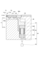
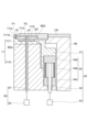
- FIG. 2 illustrates a substrate support and lift mechanism according to an example embodiment.
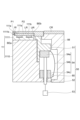
- FIG. 1 illustrates a substrate support and lift mechanism according to another exemplary embodiment.
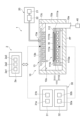
- FIG. 2 illustrates a switch and a sensor of a plasma processing apparatus according to an exemplary embodiment.
- FIG. 1 illustrates a substrate processing system according to an exemplary embodiment.
- FIG. 13 illustrates a substrate support and lift mechanism according to yet another exemplary embodiment.
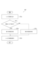
- 1 is a flow diagram illustrating a plasma processing method according to an exemplary embodiment.
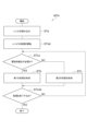
- 4 is a flow diagram illustrating a plasma processing method according to another exemplary embodiment.
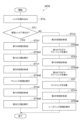
- FIG. 13 is a flow diagram illustrating a plasma processing method according to yet another exemplary embodiment.
- FIG. 1 is a block diagram of a processing circuit for implementing the operations described herein on a computer.
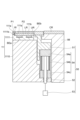
- FIG. 2 illustrates a substrate support and lift mechanism according to an example embodiment.
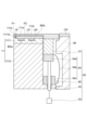
- FIG. 13 illustrates a substrate support and lift mechanism according to yet another exemplary embodiment.
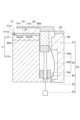
- FIG. 13 illustrates a substrate support and lift mechanism according to yet another exemplary embodiment.
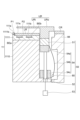
- FIG. 13 illustrates a substrate support and lift mechanism according to yet another exemplary embodiment.
- FIG. 13 illustrates a substrate support and lift mechanism according to yet another exemplary embodiment.
- FIG. 13 illustrates a substrate support and lift mechanism according to yet another exemplary embodiment.
- FIG. 13 illustrates a substrate support and lift mechanism according to yet another exemplary embodiment.
- FIG. 13 illustrates a substrate support and lift mechanism according to yet another exemplary embodiment.
- FIG. 13 illustrates a substrate support and lift mechanism according to yet another exemplary embodiment.
- FIG. 13 illustrates
- FIG. 1 is a diagram for explaining an example of the configuration of a plasma processing system.
- the plasma processing system includes a plasma processing device 1 and a control unit 2.
- the plasma processing system is an example of a substrate processing system
- the plasma processing device 1 is an example of a substrate processing device.
- the plasma processing device 1 includes a plasma processing chamber 10, a substrate support unit 11, and a plasma generation unit 12.
- the plasma processing chamber 10 has a plasma processing space.
- the plasma processing chamber 10 also has at least one gas supply port for supplying at least one processing gas to the plasma processing space, and at least one gas exhaust port for exhausting gas from the plasma processing space.
- the gas supply port is connected to a gas supply unit 20 described later, and the gas exhaust port is connected to an exhaust system 40 described later.
- the substrate support unit 11 is disposed in the plasma processing space, and has a substrate support surface for supporting a substrate.
- the plasma generating unit 12 is configured to generate plasma from at least one processing gas supplied into the plasma processing space.
- the plasma formed in the plasma processing space may be capacitively coupled plasma (CCP), inductively coupled plasma (ICP), ECR plasma (Electron-Cyclotron-Resonance Plasma), Helicon Wave Plasma (HWP), or Surface Wave Plasma (SWP), etc.
- various types of plasma generating units may be used, including AC (Alternating Current) plasma generating units and DC (Direct Current) plasma generating units.
- the AC signal (AC power) used in the AC plasma generating unit has a frequency in the range of 100 kHz to 10 GHz.
- AC signals include RF (Radio Frequency) signals and microwave signals.
- the RF signal has a frequency in the range of 100 kHz to 150 MHz.
- the control unit 2 processes computer-executable instructions that cause the plasma processing apparatus 1 to perform the various steps described in this disclosure.
- the control unit 2 may be configured to control each element of the plasma processing apparatus 1 to perform the various steps described herein. In one embodiment, a part or all of the control unit 2 may be included in the plasma processing apparatus 1.
- the control unit 2 may include a processing unit 2a1, a storage unit 2a2, and a communication interface 2a3.
- the control unit 2 is realized, for example, by a computer 2a.
- the processing unit 2a1 may be configured to perform various control operations by reading a program from the storage unit 2a2 and executing the read program. This program may be stored in the storage unit 2a2 in advance, or may be acquired via a medium when necessary.
- the acquired program is stored in the storage unit 2a2 and is read from the storage unit 2a2 by the processing unit 2a1 and executed.
- the medium may be various storage media readable by the computer 2a, or may be a communication line connected to the communication interface 2a3.
- the processing unit 2a1 may be a CPU (Central Processing Unit).
- the memory unit 2a2 may include a RAM (Random Access Memory), a ROM (Read Only Memory), a HDD (Hard Disk Drive), a SSD (Solid State Drive), or a combination of these.
- the communication interface 2a3 may communicate with the plasma processing device 1 via a communication line such as a LAN (Local Area Network).
- FIG. 1 is a diagram for explaining an example of the configuration of a capacitively coupled plasma processing device.
- the capacitively coupled plasma processing apparatus 1 includes a plasma processing chamber 10, a gas supply unit 20, a power supply 30, and an exhaust system 40.
- the plasma processing apparatus 1 also includes a substrate support unit 11 and a gas inlet unit.
- the gas inlet unit is configured to introduce at least one processing gas into the plasma processing chamber 10.
- the gas inlet unit includes a shower head 13.
- the substrate support unit 11 is disposed in the plasma processing chamber 10.
- the shower head 13 is disposed above the substrate support unit 11. In one embodiment, the shower head 13 constitutes at least a part of the ceiling of the plasma processing chamber 10.
- the plasma processing chamber 10 has a plasma processing space 10s defined by the shower head 13, the sidewall 10a of the plasma processing chamber 10, and the substrate support unit 11.
- the plasma processing chamber 10 is grounded.
- the shower head 13 and the substrate support unit 11 are electrically insulated from the housing of the plasma processing chamber 10.
- the substrate support 11 includes a main body 111 and a ring assembly 112.
- the main body 111 has a central region 111a for supporting the substrate W and an annular region 111b for supporting the ring assembly 112.
- a wafer is an example of a substrate W.
- the annular region 111b of the main body 111 surrounds the central region 111a of the main body 111 in a plan view.
- the substrate W is disposed on the central region 111a of the main body 111
- the ring assembly 112 is disposed on the annular region 111b of the main body 111 so as to surround the substrate W on the central region 111a of the main body 111. Therefore, the central region 111a is also called a substrate support surface for supporting the substrate W, and the annular region 111b is also called a ring support surface for supporting the ring assembly 112.
- the main body 111 includes a base 1110 and an electrostatic chuck 1111.
- the base 1110 includes a conductive member.
- the conductive member of the base 1110 may function as a lower electrode.
- the electrostatic chuck 1111 is disposed on the base 1110.
- the electrostatic chuck 1111 includes a ceramic member 1111a and an electrostatic electrode 1111b disposed within the ceramic member 1111a.
- the ceramic member 1111a has a central region 111a. In one embodiment, the ceramic member 1111a also has an annular region 111b. Note that other members surrounding the electrostatic chuck 1111, such as an annular electrostatic chuck or an annular insulating member, may have the annular region 111b.
- the ring assembly 112 may be disposed on the annular electrostatic chuck or the annular insulating member, or may be disposed on both the electrostatic chuck 1111 and the annular insulating member.
- at least one RF/DC electrode coupled to an RF power source 31 and/or a DC power source 32 described later may be disposed in the ceramic member 1111a.
- the at least one RF/DC electrode functions as a lower electrode.
- the RF/DC electrode is also called a bias electrode.
- the conductive member of the base 1110 and the at least one RF/DC electrode may function as multiple lower electrodes.
- the electrostatic electrode 1111b may function as a lower electrode.
- the substrate support 11 includes at least one lower electrode.
- the ring assembly 112 includes one or more annular members.
- the one or more annular members include one or more edge rings and at least one cover ring.
- the edge rings are formed of a conductive or insulating material, and the cover rings are formed of an insulating material.
- the substrate support 11 may also include a temperature adjustment module configured to adjust at least one of the electrostatic chuck 1111, the ring assembly 112, and the substrate to a target temperature.
- the temperature adjustment module may include a heater, a heat transfer medium, a flow passage 1110a, or a combination thereof.
- a heat transfer fluid such as brine or a gas flows through the flow passage 1110a.
- the flow passage 1110a is formed in the base 1110, and one or more heaters are disposed in the ceramic member 1111a of the electrostatic chuck 1111.
- the substrate support 11 may also include a heat transfer gas supply configured to supply a heat transfer gas to a gap between the back surface of the substrate W and the central region 111a.
- the shower head 13 is configured to introduce at least one processing gas from the gas supply unit 20 into the plasma processing space 10s.
- the shower head 13 has at least one gas supply port 13a, at least one gas diffusion chamber 13b, and multiple gas inlets 13c.
- the processing gas supplied to the gas supply port 13a passes through the gas diffusion chamber 13b and is introduced into the plasma processing space 10s from the multiple gas inlets 13c.
- the shower head 13 also includes at least one upper electrode.
- the gas introduction unit may include, in addition to the shower head 13, one or more side gas injectors (SGI) attached to one or more openings formed in the sidewall 10a.
- SGI side gas injectors
- the gas supply unit 20 may include at least one gas source 21 and at least one flow controller 22.
- the gas supply unit 20 is configured to supply at least one process gas from a respective gas source 21 through a respective flow controller 22 to the showerhead 13.
- Each flow controller 22 may include, for example, a mass flow controller or a pressure-controlled flow controller.
- the gas supply unit 20 may include at least one flow modulation device that modulates or pulses the flow rate of the at least one process gas.
- the power supply 30 includes an RF power supply 31 coupled to the plasma processing chamber 10 via at least one impedance matching circuit.
- the RF power supply 31 is configured to supply at least one RF signal (RF power) to at least one lower electrode and/or at least one upper electrode. This causes a plasma to be formed from at least one processing gas supplied to the plasma processing space 10s.
- the RF power supply 31 can function as at least a part of the plasma generating unit 12.
- a bias RF signal to at least one lower electrode, a bias potential is generated on the substrate W, and ion components in the formed plasma can be attracted to the substrate W.
- the RF power supply 31 includes a first RF generating unit 31a and a second RF generating unit 31b.
- the first RF generating unit 31a is coupled to at least one lower electrode and/or at least one upper electrode via at least one impedance matching circuit and configured to generate a source RF signal (source RF power) for plasma generation.
- the source RF signal has a frequency in the range of 10 MHz to 150 MHz.
- the first RF generating unit 31a may be configured to generate multiple source RF signals having different frequencies. The generated one or more source RF signals are supplied to at least one lower electrode and/or at least one upper electrode.
- the second RF generator 31b is coupled to at least one lower electrode via at least one impedance matching circuit and configured to generate a bias RF signal (bias RF power).
- the frequency of the bias RF signal may be the same as or different from the frequency of the source RF signal.
- the bias RF signal has a lower frequency than the frequency of the source RF signal.
- the bias RF signal has a frequency in the range of 100 kHz to 60 MHz.
- the second RF generator 31b may be configured to generate multiple bias RF signals having different frequencies.
- the generated one or more bias RF signals are provided to at least one lower electrode. Also, in various embodiments, at least one of the source RF signal and the bias RF signal may be pulsed.
- the power supply 30 may also include a DC power supply 32 coupled to the plasma processing chamber 10.
- the DC power supply 32 includes a first DC generator 32a and a second DC generator 32b.
- the first DC generator 32a is connected to at least one lower electrode and configured to generate a first DC signal.
- the generated first DC signal is applied to the at least one lower electrode.
- the second DC generator 32b is connected to at least one upper electrode and configured to generate a second DC signal.
- the generated second DC signal is applied to the at least one upper electrode.
- the first and second DC signals may be pulsed.
- a sequence of voltage pulses is applied to at least one lower electrode and/or at least one upper electrode.
- the voltage pulses may have a rectangular, trapezoidal, triangular or combination thereof pulse waveform.
- a waveform generator for generating a sequence of voltage pulses from the DC signal is connected between the first DC generator 32a and at least one lower electrode.
- the first DC generator 32a and the waveform generator constitute a voltage pulse generator.
- the second DC generator 32b and the waveform generator constitute a voltage pulse generator
- the voltage pulse generator is connected to at least one upper electrode.
- the voltage pulses may have a positive polarity or a negative polarity.
- the sequence of voltage pulses may also include one or more positive polarity voltage pulses and one or more negative polarity voltage pulses within one period.
- the first and second DC generating units 32a and 32b may be provided in addition to the RF power source 31, or the first DC generating unit 32a may be provided in place of the second RF generating unit 31b.
- the exhaust system 40 may be connected to, for example, a gas exhaust port 10e provided at the bottom of the plasma processing chamber 10.
- the exhaust system 40 may include a pressure regulating valve and a vacuum pump. The pressure in the plasma processing space 10s is adjusted by the pressure regulating valve.
- the vacuum pump may include a turbomolecular pump, a dry pump, or a combination thereof.
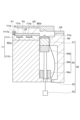
- FIG. 3 is a diagram showing a substrate support and lift mechanism according to one exemplary embodiment.
- the substrate support 11 and lift mechanism 50 shown in FIG. 3 can be employed in the plasma processing apparatus 1.
- the substrate support 11 is configured to support an edge ring UR (upper edge ring).
- the edge ring UR is part of the ring assembly 112.
- the edge ring UR is arranged to surround the substrate W on the substrate support 11.
- the edge ring UR is made of a conductive material such as silicon, silicon carbide, tungsten, etc.
- the substrate support 11 includes a base 1110 and an electrostatic chuck 1111, as described above.
- the base 1110 is a conductive member or includes a conductive member therein.
- a radio frequency power supply and/or at least one bias power supply are electrically coupled to the base 1110 (or its conductive member).
- the radio frequency power supply is a first RF generator 31a, which constitutes the plasma generator 12.
- the at least one bias power supply includes a second RF generator 31b and/or a first DC generator 32a.
- the at least one bias power supply is configured to generate an electrical bias to attract ions from the plasma to the substrate W on the substrate support 11.
- the electrical bias includes a sequence of bias RF signals and/or voltage pulses as described above.
- the electrostatic chuck 1111 is disposed on the base 1110.
- the electrostatic chuck 1111 includes a first portion P1 and a second portion P2.
- the first portion P1 has a substrate support surface (i.e., a central region 111a) as its upper surface.
- the first portion P1 and the substrate support surface have a substantially circular planar shape.
- the central axis of the first portion P1 and the substrate support surface is the central axis of the substrate support portion 11.
- the first portion P1 includes the electrostatic electrode 1111b described above. When a DC voltage is applied to the electrostatic electrode 1111b from a DC power supply, an electrostatic attractive force is generated between the first portion P1 and the substrate W.
- the first portion P1 holds the substrate W by the generated electrostatic attractive force.
- the second part P2 extends circumferentially around the central axis of the substrate support 11 so as to surround the first part P1.
- the second part P2 has a ring support surface (i.e., annular region 111b) as its upper surface.
- the second part P2 and the ring support surface have a substantially annular planar shape.
- the second part P2 may include at least one electrostatic electrode.
- the second part P2 may include electrodes BEa and BEb as at least one electrostatic electrode.
- the electrodes BEa and BEb form a bipolar electrode. A voltage is applied from at least one power source to the electrodes BEa and BEb so that a potential difference is generated between them. This generates an electrostatic attraction between the edge ring UR and the second part P2.
- the second part P2 holds the edge ring UR by the generated electrostatic attraction.
- the ring support surface extends at a lower position than the substrate support surface.
- the first portion P1 includes a sidewall surface 111s extending between the substrate support surface and the ring support surface.
- an edge ring LR (lower edge ring) may be disposed along the sidewall surface 111s and on the ring support surface.
- the edge ring LR constitutes a part of the ring assembly 112.
- the edge ring LR may be formed of a conductive material such as silicon, silicon carbide, tungsten, etc.
- the edge ring LR may be formed of an insulating material such as quartz, etc.
- the edge ring UR is disposed on the edge ring LR. The ring support surface and the sidewall surface 111s are protected by the edge ring LR.
- the substrate support 11 may further include a cover ring CR and an insulating member IM.
- the insulating member IM is made of an insulating material such as quartz and has a generally cylindrical shape.
- the insulating member IM extends in the circumferential direction around the central axis of the substrate support 11 so as to surround the base 1110 and the electrostatic chuck 1111.
- the cover ring CR has a generally disk shape and is disposed on the insulating member IM so as to surround the edge ring UR.
- the plasma processing apparatus 1 further includes a lift mechanism 50.
- the lift mechanism 50 includes a conductive ring 51, at least one rod 52, an actuator 53, and at least one connecting member 54.
- the conductive ring 51 is formed from a metal or conductive material such as aluminum, and has a generally ring shape.
- the conductive ring 51 extends circumferentially around the central axis of the substrate support 11 inside the insulating member IM, surrounding the base 1110 and the electrostatic chuck 1111.
- the conductive ring 51 is configured to be electrically coupled (e.g., conductive) to the edge ring UR while supporting the edge ring UR placed thereon.
- the exposed area on the surface of the conductive ring 51 may be covered with a film that is resistant to plasma. This film may be formed from a material such as an aluminum oxide film or yttrium fluoride, and may be formed by a method such as anodizing or thermal spraying.
- At least one rod 52 extends vertically below the conductive ring 51. At least one rod 52 may be insulating. In this case, it is possible to suppress the electrical bias from flowing into the actuator 53 via the at least one rod 52.
- the lift mechanism 50 may include a plurality of rods 52 as the at least one rod 52.
- the multiple rods 52 are arranged in a circumferential direction around the central axis of the substrate support 11. The multiple rods 52 may be arranged at equal intervals in the circumferential direction.
- the actuator 53 is disposed below the at least one rod 52 and is connected to the at least one rod 52.
- the actuator 53 is configured to move the edge ring up and down via the at least one rod 52 and the conductive ring 51.
- the actuator 53 may be, for example, a pneumatic or hydraulic cylinder, or a motor.
- the at least one connection member 54 provides an electrical connection between the conductive ring 51 and the base 1110 (or a conductive member thereof).
- the at least one connection member 54 is configured to maintain the electrical connection in response to movement of the conductive ring 51.
- the at least one connection member 54 may be configured to be deformable in response to movement of the conductive ring 51. Note that when the lift mechanism 50 includes multiple rods 52, the at least one connection member 54 may include multiple connection members 54.
- At least one connecting member 54 includes an upper portion 54a, a deformation portion 54b, and a lower portion 54c.
- the upper portion 54a, the deformation portion 54b, and the lower portion 54c are formed from a conductive material.
- the upper portion 54a is disposed directly below the conductive ring 51 and is fixed to the conductive ring 51.
- the upper portion 54a is electrically connected to the conductive ring 51.
- the lower portion 54c is disposed below the upper portion 54a and is fixed to the base 1110.
- the lower portion 54c is electrically connected to the base 1110.
- the deformation portion 54b extends between the upper portion 54a and the lower portion 54c.
- the upper end of the deformation portion 54b is fixed to the upper portion 54a, and the lower end of the deformation portion 54b is fixed to the lower portion 54c.
- the deformation portion 54b is electrically connected to the upper portion 54a and the lower portion 54c.
- the deformation portion 54b may be a bellows as shown in FIG. 3.
- At least one rod 52 penetrates the lower portion 54c, passes through the deformation portion 54b, and extends to the region directly below the upper portion 54a.
- the edge ring UR is moved upward via the upper portion 54a and the conductive ring 51.
- the edge ring UR is moved upward in accordance with a decrease in its thickness in order to reduce the difference between the upper end position of the plasma sheath on the substrate W and the upper end position of the plasma sheath on the edge ring UR (see FIG. 12).
- the first state e.g., a conductive state
- the edge ring UR since the edge ring UR does not enter an electrically floating state, the edge ring UR can exert a function of reducing the difference between the upper end position of the plasma sheath on the substrate W and the upper end position of the plasma sheath on the edge ring UR.
- connection member 54 may be a cylindrical member having a plurality of slits formed in its side wall surface so that it can be elastically deformed in the longitudinal direction.
- connection member 54 may be a flexure.
- the lift mechanism 50 can electrically couple (e.g., conduct) the conductive ring 51 to the edge ring UR while the edge ring UR on the conductive ring 51 is supported by the conductive ring 51. That is, the lift mechanism 50 can create a first state (e.g., a conductive state) in which the edge ring UR and the base 1110 are electrically coupled to each other. Note that in the state shown in FIG. 3, the conductive ring 51 is spaced downward from the edge ring UR, but when the conductive ring 51 is in contact with the edge ring UR placed on it, the first state (e.g., a conductive state) in which the edge ring UR and the base 1110 are electrically coupled to each other is created.
- a first state e.g., a conductive state
- the plasma processing apparatus 1 further includes a switch 80 (see FIG. 5).
- the switch 80 is configured to be able to switch between a first state (e.g., a conductive state) in which the edge ring UR and the base 1110 are electrically coupled to each other, and a second state (e.g., a non-conductive state) in which the edge ring UR and the base 1110 are electrically isolated from each other.
- the switching between the first state and the second state by the switch 80 can be controlled by the control unit 2.
- the switch 80 is a lift mechanism 50.
- the lift mechanism 50 can lower the conductive ring 51 downward via the rod 52 by the actuator 53, and separate the conductive ring 51 from the edge ring UR. That is, the lift mechanism 50 can create the second state by separating the conductive ring 51 from the edge ring UR.
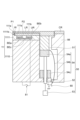
- FIG. 4 is a diagram showing a substrate support and lift mechanism of another exemplary embodiment.
- the substrate support 11 and lift mechanism 50 shown in FIG. 4 can be employed in the plasma processing apparatus 1.
- the embodiment of FIG. 4 will be described below in terms of the differences from the embodiment of FIG. 3.
- the lift mechanism 50 may have a deformation portion 54b that is a contact band instead of a bellows.
- the upper end of the deformation portion 54b may be fixed to the conductive ring 51.
- the lower end of the deformation portion 54b may be fixed to the base 1110.
- the deformation portion 54b shown in FIG. 4 has flexibility in the vertical direction.
- the deformation portion 54b may have a generally arc shape that bulges outward.
- the insulating member IM may provide a recess into which a portion of the deformation portion 54b is disposed.
- the plasma processing apparatus 1 including the lift mechanism 50 shown in FIG. 4 further includes a switch 80.
- the switch 80 may be part of the lift mechanism 50.
- the switch 80 includes a switching element and is connected between the connection member 54 and the conductive ring 51 or between the connection member 54 and the base 1110.
- the switching element of the switch 80 When the switching element of the switch 80 is in the ON state (closed state), the above-mentioned first state is formed.
- the switching element of the switch 80 is in the OFF state (open state), the above-mentioned second state is formed.
- the switching between the first state and the second state by the switch 80 i.e., the switching element
- FIG. 6 is a diagram showing a substrate processing system according to an exemplary embodiment.
- the substrate processing system PS shown in FIG. 6 includes a transfer module TM, multiple process modules PM1 to PM7 (multiple substrate processing modules), and a controller MC.
- the substrate processing system PS may further include stages LPa to LPd, containers FUa to FUd, a loader module LM, an aligner AN, a load lock module LL1, a load lock module LL2, and a stocker module RSM (ring stocker).
- the number of stages, containers, and load lock modules in the substrate processing system PS may be any number equal to or greater than one.
- the number of process modules in the substrate processing system PS may be any number equal to or greater than two.
- the platforms LPa to LPd are arranged along one edge of the loader module LM.
- the containers FUa to FUd are mounted on the platforms LPa to LPd, respectively.
- Each of the containers FUa to FUd is, for example, a container called a FOUP (Front Opening Unified Pod).
- Each of the containers FUa to FUd is configured to accommodate a substrate W therein.
- the loader module LM has a transfer chamber.
- the pressure in the transfer chamber of the loader module LM is set to atmospheric pressure.
- the loader module LM has a transfer robot LMR.
- the transfer robot LMR is controlled by the controller MC.
- the transfer robot LMR is configured to transfer a substrate W through the transfer chamber of the loader module LM.
- the transfer robot LMR can transfer the substrate W between each of the containers FUa to FUd and the aligner AN, between the aligner AN and each of the load lock modules LL1, LL2, and between each of the load lock modules LL1, LL2 and each of the containers FUa to FUd.
- the aligner AN is connected to the loader module LM.
- the aligner AN is configured to adjust (align) the position of the substrate W.
- Each of the load lock modules LL1 and LL2 is connected between the transfer chamber of the loader module LM and the transfer chamber TC of the transfer module TM.
- Each of the load lock modules LL1 and LL2 provides a preliminary decompression chamber.
- a gate valve is provided between each of the preliminary decompression chambers of the load lock modules LL1 and LL2 and the transfer chamber of the loader module LM.
- a gate valve is provided between each of the preliminary decompression chambers of the load lock modules LL1 and LL2 and the transfer chamber TC of the transfer module TM.
- the transport module TM has a transport chamber TC (vacuum transport chamber) and a transport robot TR.
- the transport chamber TC is configured so that the space inside it can be depressurized.
- the transport robot TR includes a pick TP (end effector).
- the transport robot TR may include at least two picks TP. In the illustrated example, the transport robot TR includes two picks TP. One of the two picks TP is provided above the other.
- the transport robot TR is configured to transport a substrate W placed on any one of the two picks TP via the transport chamber TC.
- the transport robot TR is controlled by a control unit MC.
- the transfer module TM may be provided with position detection sensors S11 and S12.
- the position detection sensors S11 and S12 are provided on the transfer path of the substrate W and edge ring from the transfer module TM to the process module PM1.
- the position detection sensors S11 and S12 are used to correct the position of the substrate W and edge ring transferred from the transfer module TM to the process module PM1.
- the position detection sensors S11 and S12 are provided, for example, near the gate valve separating the transfer module TM and the process module PM1.
- the position detection sensors S11 and S12 are arranged, for example, such that the distance between them is smaller than the outer diameter of the substrate W and smaller than the inner diameter of the edge ring.
- the transfer module TM may be provided with position detection sensors S21, S22, S31, S32, S41, S42, S51, S52, S61, S62, S71, and S72, similar to the position detection sensors S11 and S12.
- the position detection sensors S21 and S22 are provided on the transport path of the substrate W and edge ring from the transport module TM to the process module PM2.
- the position detection sensors S31 and S32 are provided on the transport path of the substrate W and edge ring from the transport module TM to the process module PM3.
- the position detection sensors S41 and S42 are provided on the transport path of the substrate W and edge ring from the transport module TM to the process module PM4.
- the position detection sensors S51 and S52 are provided on the transport path of the substrate W and edge ring from the transport module TM to the process module PM5.
- the position detection sensors S61 and S62 are provided on the transport path of the substrate W and edge ring from the transport module TM to the process module PM6.
- the position detection sensors S71 and S72 are provided on the transport path of the substrate W and edge ring from the transport module TM to the process module PM7.
- the transport robot TR is configured to transport an edge ring for a substrate support of any one of the process modules PM1 to PM7.
- the edge ring is an edge ring UR or a ring set including an edge ring UR and an edge ring LR.
- the edge ring is placed on any one of the two picks TP and transported.
- Each pick TP has a sensor TS.
- the sensor TS is an optical sensor and configured to measure the position of a ring member such as an edge ring on the substrate support.
- Each of the process modules PM1 to PM7 is an apparatus configured to perform dedicated substrate processing, and has a processing chamber (substrate processing chamber).
- a gate valve is provided between the processing chamber and the transfer chamber TC.
- At least one of the process modules PM1 to PM7 is a plasma processing apparatus 1.
- the stocker module RSM (ring stocker) is connected to the transfer chamber TC via a gate valve.
- the stocker module RSM has a chamber and can accommodate multiple edge rings therein.
- the control unit MC is configured to control each part of the substrate processing system PS.
- the control unit MC may be a computer equipped with a processor, a storage device, an input device, a display device, etc.
- the control unit MC executes a control program stored in the storage device, and controls each part of the substrate processing system PS based on the recipe data stored in the storage device.
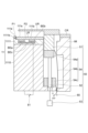
- FIG. 7 is a diagram showing a substrate support and lift mechanism according to yet another exemplary embodiment.
- the substrate support 11 and lift mechanism 50 shown in FIG. 7 may be employed in a plasma processing apparatus 1.
- the plasma processing apparatus 1 including the substrate support 11 and lift mechanism 50 shown in FIG. 7 may be employed as a process module of a substrate processing system PS.
- the embodiment of FIG. 7 will be described below in terms of differences from the embodiment of FIG. 3.
- the substrate support 11 provides a plurality of through holes that pass through it in a vertical direction.
- the plurality of through holes in the substrate support 11 are arranged in a circumferential direction around the central axis of the substrate support 11.
- the plurality of through holes in the substrate support 11 may be arranged at equal intervals.
- the edge ring LR is formed with a plurality of through holes that are aligned with the plurality of through holes in the substrate support 11.
- the edge ring UR can be lifted upward from the substrate support 11 by a lift mechanism 60.
- the lift mechanism 60 includes a plurality of lift pins 61 and an actuator 62.
- the plurality of lift pins 61 are inserted into a plurality of through holes in the substrate support 11, respectively.
- the actuator 62 is connected to the plurality of lift pins 61 and is configured to move the plurality of lift pins 61 up and down.
- the edge ring UR is lifted upward from the substrate support 11.
- the transport robot TR moves the pick TP below the edge ring UR.
- the edge ring UR is handed over to the pick TP.
- the edge ring UR is then transported to the stocker module RSM by the transport robot TR.
- the replacement edge ring UR is transported from the stocker module RSM into the chamber 10 by the transport robot TR.
- the edge ring UR is then handed over to the multiple lift pins 61 as the multiple lift pins 61 are moved upward by the actuator 62.
- the pick TP then moves outside the chamber 10, and the multiple lift pins 61 move downward.
- the replacement edge ring UR is placed on the substrate support 11.
- the plasma processing apparatus 1 including the lift mechanism 50 shown in FIG. 7 includes a lift mechanism 60 as a switch 80.
- all of the lift pins 61 are formed from an insulating material.
- the lift mechanism 60 positions all of the lift pins 61 so that the edge ring UR is supported on the conductive ring 51 and electrically coupled to the conductive ring 51, the first state described above is created.
- the lift mechanism 60 lifts the edge ring UR upward from the conductive ring 51 and pulls it away from the conductive ring 51, the second state described above is created.
- the plasma processing apparatus 1 may include another lift mechanism instead of or in addition to the lift mechanism 60.
- the other lift mechanism may be configured to lift the ring set including both the edge ring UR and the edge ring LR upward from the substrate support portion 11 and/or the conductive ring 51.
- the switch 80 described above can switch between the first and second states as necessary.
- the electrical bias and/or source RF signal is not supplied from the base 1110 to the edge ring UR via the conductive ring 51.
- this switch 80 when the second state is formed, it is possible to suppress wear of the edge ring UR due to chemical species from the plasma by performing plasma processing in the chamber 10.
- FIG. 5 illustrates a switch and a sensor of a plasma processing apparatus according to one exemplary embodiment.
- the plasma processing apparatus 1 may further include at least one sensor 90, as shown in FIG. 5.
- the at least one sensor 90 is configured to measure the amount of deposition on the edge ring UR.
- the sensor 90 may include at least one selected from the group consisting of a sensor 91, a sensor 92, and a sensor 93.
- the sensor 91 is an optical emission spectrometer and is configured to analyze the optical emission of the plasma in the chamber 10.
- the sensor 91 measures different optical emission intensities at a predetermined wavelength when deposits are present on the edge ring UR and when deposits have been removed from the edge ring UR. Therefore, the sensor 91 can estimate the amount of deposits on the edge ring UR from the measured optical emission intensity.
- the sensor 92 is an optical sensor that includes a light source such as a laser, and is configured to detect the thickness of the deposits on the edge ring UR.
- the sensor 92 is disposed, for example, on the ceiling of the chamber 10. The sensor 92 allows the amount of deposits on the edge ring UR to be estimated from the measured thickness of the deposits.
- the sensor 93 is an impedance measuring device and is connected to the base 1110.
- the impedance on the base 1110 side as seen from the sensor 93 changes depending on the amount of deposits on the edge ring UR.
- the sensor 93 makes it possible to estimate the amount of deposits on the edge ring UR from the measured impedance.
- FIG. 8 to 10 is a flow chart showing a plasma processing method according to an exemplary embodiment.
- the plasma processing methods shown in each of Figs. 8 to 10 can be performed using a plasma processing apparatus 1.
- each part of the plasma processing apparatus 1 can be controlled by a control unit 2.
- step STa The plasma processing method shown in FIG. 8 (hereinafter referred to as "method MT") starts with step STa.
- a recipe is read by the control unit 2.
- the control unit 2 determines whether the loaded recipe is a product recipe.
- a product recipe is a recipe for plasma processing of a substrate W on the substrate support unit 11. If it is determined in process STJ that the loaded recipe is a product recipe, the control unit 2 controls the switch 80 to create the above-mentioned first state in process STb. On the other hand, if it is determined in process STJ that the loaded recipe is not a product recipe, the control unit 2 controls the switch 80 to create the above-mentioned second state in process STc.
- the control unit 2 executes the plasma processing specified in the loaded recipe. If the loaded recipe is a product recipe, the control unit 2 controls each part of the plasma processing apparatus 1 to perform plasma processing, such as plasma etching, on the substrate W on the substrate support 11 in step STd while maintaining the above-mentioned first state. On the other hand, if the loaded recipe is not a product recipe, the control unit 2 controls each part of the plasma processing apparatus 1 to perform plasma cleaning of the chamber 10 in step STd while maintaining the above-mentioned second state.
- the loaded recipe is a product recipe
- the control unit 2 controls each part of the plasma processing apparatus 1 to perform plasma cleaning of the chamber 10 in step STd while maintaining the above-mentioned second state.
- step STa The plasma processing method shown in FIG. 9 (hereinafter, referred to as "method MTA") starts with step STa, similar to method MT.
- the control unit 2 controls each part of the plasma processing apparatus 1 to start the execution of the plasma processing specified in the loaded recipe.
- This plasma processing may be plasma cleaning of the chamber 10.
- this plasma processing is plasma cleaning for removing carbon-containing deposits on the edge ring UR.
- the gas used in this plasma processing includes a gas capable of removing deposits, such as an oxygen-containing gas.
- the control unit 2 may control the switch 80 to form the first state described above.
- the control unit 2 determines whether electrical connection between the edge ring UR and the base 1110 is necessary. Specifically, if the amount of deposits on the edge ring UR determined by measurement by at least one sensor 90 is greater than a threshold value, the control unit 2 determines that electrical connection between the edge ring UR and the base 1110 is necessary in process STAJ. On the other hand, if the amount of deposits on the edge ring UR determined by measurement by at least one sensor 90 is equal to or less than a threshold value, the control unit 2 determines that electrical connection between the edge ring UR and the base 1110 is not necessary in process STAJ.
- the emission intensity of the plasma at a predetermined wavelength (e.g., the wavelength of emission based on carbon) measured by the sensor 91 is equal to or less than a threshold value
- the thickness of the deposits on the edge ring UR measured by the sensor 92 is equal to or less than a threshold value
- the impedance measured by the sensor 93 is equal to or less than a threshold value
- step STAJ If it is determined in step STAJ that electrical connection between the edge ring UR and the base 1110 is necessary, the control unit 2 controls the switch 80 to form the first state described above in step STb. On the other hand, if it is determined in step STAJ that electrical connection between the edge ring UR and the base 1110 is not necessary, the control unit 2 controls the switch 80 to form the second state described above in step STc.
- step STAJb the control unit 2 determines whether or not to end the process. If it is determined not to end the process in step STAJb, the plasma process started in step STAd is continued, and the process from step STAJ is repeated. On the other hand, if it is determined to end the process in step STAJb, the control unit 2 ends the method MTA.
- method MTB The plasma processing method shown in FIG. 10 (hereinafter referred to as "method MTB") starts with step STa, similar to method MT. Then, in method MTB, a determination is made for step STJ, similar to method MT. Note that the edge ring UR is placed on the substrate support 11 and conductive ring 51 at the start of method MTB or immediately after step STJ.
- control unit 2 controls the switch 80 in process STb1 to create the first state described above.
- the control unit 2 controls each part of the plasma processing apparatus 1 to execute the first process specified in the loaded recipe.
- the first process includes plasma etching for forming a recess in the substrate W on the substrate support 11 as the plasma processing specified in the recipe.
- the gas used in this plasma etching may include fluorocarbon and/or hydrofluorocarbon.
- control unit 2 controls the switch 80 to create the second state described above.
- each part of the plasma processing apparatus 1 is controlled to perform the ashing process specified in the loaded recipe.
- chemical species from the plasma generated from the ashing gas remove deposits from the substrate W on the substrate support 11.
- the ashing gas may contain an oxygen-containing gas.
- control unit 2 controls the switch 80 to create the first state described above.
- the control unit 2 controls each part of the plasma processing apparatus 1 to execute the second step specified in the loaded recipe.
- the second step includes plasma etching for increasing the depth of the recess in the substrate W on the substrate support 11 as the plasma processing specified in the recipe.
- the gas used in this plasma etching may contain fluorocarbon and/or hydrofluorocarbon, similar to the gas used in the first step.
- control unit 2 controls the switch 80 in process STc3 to create the above-mentioned second state.
- control unit 2 controls each part of the plasma processing device 1 to perform the plasma processing specified in the loaded recipe, i.e., the first plasma cleaning of the chamber 10.
- the gas used in process STBd4 may contain an oxygen-containing gas.
- control unit 2 controls the switch 80 to create the first state described above.
- control unit 2 controls each part of the plasma processing device 1 to perform the plasma processing specified in the loaded recipe, i.e., the second plasma cleaning of the chamber 10.
- the gas used in process STBd5 may contain an oxygen-containing gas.
- the edge ring on the substrate support 11 is replaced with an edge ring transported from the stocker module RSM using the transport robot TR.
- control unit 2 controls the switch 80 to create the second state described above.
- control unit 2 controls each part of the plasma processing device 1 to perform the plasma processing specified in the loaded recipe, i.e., the seasoning processing of the chamber 10.
- plasma is generated in the chamber 10 from the seasoning gas.
- FIG. 13 and 14 is a diagram showing a substrate support and a lift mechanism according to yet another exemplary embodiment.
- the substrate support 11 and lift mechanism 50 shown in Figures 13 and 14 can be employed in a plasma processing apparatus 1.
- Each configuration in the embodiment of Figures 13 and 14 is substantially similar to the corresponding configuration in the embodiment of Figure 4.
- the plasma processing apparatus 1 including the substrate support 11 and lift mechanism 50 shown in Figures 13 and 14 can be used in method MT.
- the control unit 2 controls the switch 80 to form the first state described above in step STb.
- the control unit 2 controls each part of the plasma processing apparatus 1 to perform a plasma processing on the substrate W in step STd.
- a deposit may be formed on the lower surface of the edge ring UR and/or the upper surface (the ring support surface or the upper surface of the edge ring LR) facing the lower surface of the edge ring UR.
- the deposit may contain a component contained in the processing gas used in the plasma processing in step STd.
- the deposit may be formed of a carbon-containing substance. Alternatively, the deposit may be formed of a metal-containing substance.
- the control unit 2 controls the switch 80 to form the above-mentioned second state in step STb.
- the control unit 2 controls each part of the plasma processing apparatus 1 to perform plasma cleaning in step STd.
- the control unit 2 also controls the lift mechanism 50 to set the height position of the edge ring UR when plasma cleaning is being performed (see FIG. 14) to a position higher than the height position of the edge ring UR when the above-mentioned plasma processing is being performed on the substrate W (see FIG. 13).
- a source RF signal may be supplied from the first RF generating unit 31a to generate plasma from the cleaning gas.
- the level of the bias signal from the bias power supply i.e., the power level of the bias RF signal or the level of the voltage pulse (the potential difference with respect to the reference potential of the voltage pulse (e.g., 0 V)) may be set to zero or a low level.
- an oxygen-containing gas may be supplied into the chamber 10 as a cleaning gas to generate plasma.
- a source RF signal may be supplied from the first RF generating unit 31a to generate plasma from the cleaning gas.
- the level of the bias signal from the bias power supply i.e., the power level of the bias RF signal or the level of the voltage pulse (the potential difference with respect to the reference potential of the voltage pulse (e.g., 0 V)) may have a high level set to remove the deposits by ion sputtering.
- FIG. 15 is a diagram showing a substrate support and a lift mechanism according to yet another exemplary embodiment.
- the lift mechanism 50 shown in FIG. 15 can be employed in the plasma processing apparatus 1 in place of the lift mechanism 50 shown in FIGS. 13 and 14.
- the plasma processing apparatus 1 including the lift mechanism 50 shown in FIG. 15 can also perform the method MT in the same manner as the plasma processing apparatus 1 including the lift mechanism 50 shown in FIGS. 13 and 14.
- the lift mechanism 50 shown in FIG. 15 will be described below from the perspective of the differences from the lift mechanism 50 shown in FIGS. 13 and 14.
- the edge ring UR includes an inner circumference portion URi and an outer circumference portion URo.
- the inner circumference portion URi extends inside the outer circumference portion URo and is disposed above the second portion P2.
- the outer circumference portion URo is positioned on the conductive ring 51 while being supported by the conductive ring 51.
- the outer circumference portion URo has a vertical length set so as to hide the conductive ring 51 from the space above the substrate support portion 11 when plasma cleaning is performed in process STd.
- the outer circumference portion URo has a vertical length set so as to be interposed between the space above the substrate support portion 11 and the conductive ring 51 when plasma cleaning is performed in process STd. This protects the conductive ring 51 from the plasma generated in process STd.
- FIG. 16 is a diagram showing a substrate support and a lift mechanism according to yet another exemplary embodiment.
- the lift mechanism 50 shown in FIG. 16 can be employed in the plasma processing apparatus 1 in place of the lift mechanism 50 shown in FIGS. 13 and 14.
- the method MT can be performed in the plasma processing apparatus 1 including the lift mechanism 50 shown in FIG. 16 in the same manner as in the plasma processing apparatus 1 including the lift mechanism 50 shown in FIGS. 13 and 14.
- the lift mechanism 50 shown in FIG. 16 will be described below from the perspective of the differences from the lift mechanism 50 shown in FIGS. 13 and 14.
- the lift mechanism 50 shown in FIG. 16 further includes a coating 51c.
- the coating 51c covers the surface of the conductive ring 51 to protect the conductive ring 51 from plasma.
- the coating 51c is made of a plasma-resistant material (e.g., yttria).
- the coating 51c formed between the edge ring UR and the conductive ring 51, i.e., the coating 51c formed on the upper surface of the conductive ring 51 may have a capacitance of 10,000 pF or more for electrical coupling (capacitive coupling) between the edge ring UR and the base 1110.
- FIG. 17 and FIG. 18 are diagram showing a substrate support and a lift mechanism according to yet another exemplary embodiment.
- the substrate support 11 and the lift mechanism 50 shown in FIG. 17 and FIG. 18 can be adopted in the plasma processing apparatus 1 in place of the substrate support 11 and the lift mechanism 50 shown in FIG. 13 and FIG. 14.
- the method MT can be performed in the plasma processing apparatus 1 including the substrate support 11 and the lift mechanism 50 shown in FIG. 17 and FIG. 18 in the same manner as the plasma processing apparatus 1 including the substrate support 11 and the lift mechanism 50 shown in FIG. 13 and FIG. 14.
- the substrate support 11 and the lift mechanism 50 shown in FIG. 17 and FIG. 18 will be described from the viewpoint of the differences from the substrate support 11 and the lift mechanism 50 shown in FIG. 13 and FIG. 14.
- the lift mechanism 50 further includes a protective member 51p.
- the protective member 51p has a ring shape extending circumferentially around the central axis of the substrate support portion 11.
- the protective member 51p is conductive and is mounted on the conductive ring 51 so as to protect the conductive ring 51 from plasma.
- the protective member 51p is made of a material that is resistant to plasma.
- the protective member 51p may be made of the same material as the edge ring UR. In this embodiment, when the edge ring UR is supported by the conductive ring 51, it is electrically coupled to the conductive ring 51 via the protective member 51p.
- the plasma processing apparatus 1 further includes a lift mechanism 70.
- the lift mechanism 70 includes a plurality of lift pins 71 and an actuator 72.
- the plurality of rods 52 of the lift mechanism 50 shown in Figure 17 and the plurality of lift pins 71 shown in Figure 18 can be arranged alternately along the circumferential direction with respect to the central axis of the substrate support 11.
- the plurality of rods 52 and the plurality of lift pins 71 can be arranged at equal intervals.
- the multiple lift pins 71 can be inserted into multiple through holes that vertically penetrate the conductive ring 51 and the protective member 51p.
- the actuator 72 is configured to move the multiple lift pins 71 up and down under the control of the control unit 2.
- the lift mechanism 70 has retracted the multiple lift pins 71 to a lower position so that the upper ends of the multiple lift pins 71 do not come into contact with the edge ring UR, the above-mentioned first state is created.
- the lift mechanism 70 is lifting the edge ring UR upward from the protective member 51p using the multiple lift pins 71, the above-mentioned second state is created.
- the lift mechanism 70 constitutes a switch 80.
- control unit 2 controls the lift mechanism 70, i.e., the switch 80, to form the first state described above in step STb.
- control unit 2 controls each part of the plasma processing apparatus 1 to perform plasma processing on the substrate W in step STd.
- the control unit 2 controls the lift mechanism 70, i.e., the switch 80, to form the above-mentioned second state in step STb.
- the control unit 2 controls each part of the plasma processing apparatus 1 to perform plasma cleaning in step STd.
- the control unit 2 controls the lift mechanism 70 to set the height position of the edge ring UR when plasma cleaning is being performed to a position higher than the height position of the edge ring UR when the above-mentioned plasma processing is being performed on the substrate W.
- FIG. 19 and FIG. 20 are diagram showing a substrate support and a lift mechanism according to yet another exemplary embodiment.
- the substrate support 11 and the lift mechanism 50 shown in FIG. 19 and FIG. 20 can be adopted in the plasma processing apparatus 1 in place of the substrate support 11 and the lift mechanism 50 shown in FIG. 13 and FIG. 14.
- the method MT can be performed in the plasma processing apparatus 1 including the substrate support 11 and the lift mechanism 50 shown in FIG. 19 and FIG. 20 in the same manner as the plasma processing apparatus 1 including the substrate support 11 and the lift mechanism 50 shown in FIG. 13 and FIG. 14.
- the substrate support 11 and the lift mechanism 50 shown in FIG. 19 and FIG. 20 will be described from the viewpoint of the differences from the substrate support 11 and the lift mechanism 50 shown in FIG. 13 and FIG. 14.
- the electrostatic chuck 1111 has an electrode BEc built in below the edge ring UR, i.e., in the second portion P2.
- the electrode BEc is electrically connected to the base 1110 via the switching element 81.
- control unit 2 When performing plasma processing on the substrate W in process STd, the control unit 2 may set the state of the switching element 81 to the OFF state (open state) to cut off the electrical connection between the electrode BEc and the base 1110. When performing plasma processing on the substrate W in process STd, the control unit 2 controls the switch 80 (switching element) to form the first state described above.
- the control unit 2 controls the lift mechanism 50 to set the height position of the edge ring UR to a position higher than the height position of the edge ring UR when the above-mentioned plasma processing is performed on the substrate W.
- the control unit 2 sets the state of the switching element 81 to the ON state (closed state) to establish an electrical connection between the electrode BEc and the base 1110.
- the control unit 2 controls the switch 80 (switching element) to form the above-mentioned second state and connect the edge ring UR to ground via the conductive ring 51.
- FIG. 11 is a block diagram of a processing circuit that performs the operations described herein on a computer.
- FIG. 11 illustrates a processing circuit 130 that can be used to control a control process on any computer. Descriptions or blocks in the flow chart represent modules, segments, or portions of code that include one or more executable instructions for performing a particular logical function or step of the process.
- the processing circuitry 130 includes a CPU 1200 that performs one or more of the control processes described above/below.
- Processing data and instructions may be stored in memory 1202. These processing data and instructions may be stored on a storage medium disk 1204, such as a hard disk drive (HDD) or a portable storage medium, or may be stored remotely.
- a storage medium disk 1204 such as a hard disk drive (HDD) or a portable storage medium, or may be stored remotely.
- the disclosure as claimed is not limited by the form of the computer readable medium on which the processing instructions according to the present invention are stored.
- these instructions may be stored on a CD, DVD, flash memory, RAM, ROM, PROM, EPROM, EEPROM, hard disk, or any other information processing device such as a server and/or computer with which the processing circuitry 130 communicates.
- the disclosure as claimed may be provided as a utility application, a background daemon, a component of an operating system, or a combination thereof, and may be executed in conjunction with the CPU 1200 and an operating system known to those skilled in the art, such as Microsoft Windows (registered trademark), UNIX (registered trademark), Solaris (registered trademark), LINUX (registered trademark), Apple MAC-OS, etc.
- Microsoft Windows registered trademark
- UNIX registered trademark
- Solaris registered trademark
- LINUX registered trademark
- Apple MAC-OS etc.
- the hardware elements making up the processing circuit 130 can be realized by a variety of circuit elements. Furthermore, each of the functions of the above-described embodiments can be implemented by a circuit including one or more processing circuits. As shown in FIG. 11, the processing circuit includes a specifically programmed processing device, such as a processing unit (CPU) 1200. The processing circuit also includes devices such as application specific integrated circuits (ASICs) or conventional circuit components configured to implement the described functions.
- ASICs application specific integrated circuits
- the processing circuitry 130 includes a CPU 1200 that performs the above-described processing.
- the processing circuitry 130 may be a general-purpose computer or a specific dedicated machine.
- the processing circuitry 130 functions as a specific dedicated machine when the processing device 1200 is programmed to control each part of the plasma processing device 1, such as the gas supply unit 20, the power supply 30, the lift mechanism 50, and the switch 80.
- CPU 1200 may be implemented on an FPGA, ASIC, PLD, or using discrete logic circuitry, as will be appreciated by those skilled in the art. Additionally, CPU 1200 may be implemented as multiple processing devices that cooperate to perform the instructions of the process of the present invention described above in parallel.
- the processing circuitry 130 of FIG. 11 also includes a network controller 1206, such as an Intel Ethernet PRO network interface card from Intel Corporation, USA, for interfacing with a network 1228.
- the network 1228 may be a public network, such as the Internet, a private network, such as a LAN or WAN, or any combination thereof, and may also include sub-networks, such as PSTN or ISDN.
- the network 1228 may also be wired, such as an Ethernet network, or wireless, such as a cellular network, including EDGE, 3G, and 4G wireless cellular systems.
- the wireless network may also be Wi-Fi, Bluetooth, or any other known form of wireless communication.
- the processing circuitry 130 further includes a display device controller 1208, such as a graphics card or graphics adapter, for interfacing with a display device 1210, such as a monitor.
- a display device controller 1208 such as a graphics card or graphics adapter
- a general purpose I/O interface 1212 interfaces with a keyboard and/or mouse 1214, and a touch panel 1216, which may be integral with or separate from the display device 1210.
- the general purpose I/O interface is also connected to various peripheral devices 1218, such as printers and scanners.
- the storage controller 1224 is connected to the storage media disk 1204 via a communication bus 1226, such as ISA, EISA, VESA, PCI, etc., and all components of the processing circuitry 130 are connected to each other.
- a communication bus 1226 such as ISA, EISA, VESA, PCI, etc.
- all components of the processing circuitry 130 are connected to each other.
- the general features and functions of the display device 1210, keyboard and/or mouse 1214, display device controller 1208, storage controller 1224, network controller 1206, audio controller 1220, and general purpose I/O interface 1212 are not described herein as they are known.
- circuits configured to implement the features described herein may be implemented in multiple circuit units (e.g., chips) or these features may be combined into the circuitry of a single chipset.
- the functions and features described herein may also be performed by various components distributed across the system.
- one or more processing devices may perform the functions of these systems, where the processing devices are distributed across multiple components communicating within a network.
- Distributed components may include various human interface and communication devices (such as display monitors, smartphones, tablets, personal digital assistants (PDAs), etc.), as well as one or more client and server machines that may share processing.
- the network may be a private network, such as a LAN or WAN, or a public network, such as the Internet.
- Input to the system may be received by direct user input or remotely in real time or as a batch process.
- some of the embodiments may be implemented on modules or hardware that are not identical to those described above. Accordingly, other embodiments are within the scope of the claims.
- any of the above-mentioned containers FUa to FUd may be used as the stocker module RSM.
- 1...plasma processing device 2...control unit, 10...chamber, 11...substrate support unit, 12...plasma generation unit, 1110...base, 1111...electrostatic chuck, 50...lift mechanism, 51...conductive ring, 52...rod, 53...actuator, 54...connecting member, 80...switch.
Landscapes
- Chemical & Material Sciences (AREA)
- Physics & Mathematics (AREA)
- Engineering & Computer Science (AREA)
- Plasma & Fusion (AREA)
- Analytical Chemistry (AREA)
- Health & Medical Sciences (AREA)
- Epidemiology (AREA)
- Public Health (AREA)
- General Chemical & Material Sciences (AREA)
- Chemical Kinetics & Catalysis (AREA)
- Materials Engineering (AREA)
- Mechanical Engineering (AREA)
- Metallurgy (AREA)
- Organic Chemistry (AREA)
- Electromagnetism (AREA)
- Spectroscopy & Molecular Physics (AREA)
- Drying Of Semiconductors (AREA)
- Chemical Vapour Deposition (AREA)
Abstract
Description
Claims (21)
- チャンバと、
前記チャンバ内の基板支持部であり、
基台と、
該基台上の静電チャックと、
を含む、該基板支持部と、
高周波電源を含み、前記チャンバ内でプラズマを生成するように構成されたプラズマ生成部と、
前記基板支持部上の前記基板に前記プラズマからイオンを引き込むために電気バイアスを発生するように構成されたバイアス電源であり、前記バイアス電源及び/又は前記高周波電源は前記基台に電気的に結合されている、該バイアス電源と、
導電性を有し、前記基板支持部上の基板を囲むように配置されるエッジリングと、
前記エッジリングを上下に移動させるように構成されたリフト機構であり、
その上に載置される前記エッジリングを支持した状態で該エッジリングに電気的に結合する導電リングと、
前記導電リングの下方で鉛直方向に延びるロッドと、
前記ロッド及び前記導電リングを介して前記エッジリングを上下に移動させるように構成されたアクチュエータと、
前記導電リングと前記基台との間の電気的接続を提供する接続部材と、
を含む、該リフト機構と、
前記エッジリングと前記基台とが互いに電気的に結合される第1の状態と前記エッジリングと前記基台とが互いから電気的に分離される第2の状態を切り替え可能に構成された切替器と、
前記切替器による前記第1の状態と前記第2の状態の切り替えを制御するように構成された制御部と、
を備えるプラズマ処理装置。 - 前記リフト機構は、前記切替器であり、前記エッジリングから前記導電リングを引き離すように前記導電リングを前記アクチュエータによって降下させることにより前記第2の状態を形成するように構成されている、請求項1に記載のプラズマ処理装置。
- 前記切替器は、前記接続部材と前記導電リングとの間又は前記接続部材と前記基台との間で接続されたスイッチング素子を含む、請求項1に記載のプラズマ処理装置。
- 前記切替器は、前記エッジリングを前記導電リングから持ち上げることにより前記第2の状態を形成するように構成された別のリフト機構を含む、請求項1に記載のプラズマ処理装置。
- 前記制御部は、
レシピによって指定されたプラズマ処理が前記基板支持部上の基板に対するプラズマ処理である場合には、前記第1の状態を形成するよう、前記切替器を制御し、
前記レシピによって指定されたプラズマ処理が前記チャンバのプラズマクリーニングである場合には、前記第2の状態を形成するよう、前記切替器を制御する、
ように構成されている、
請求項1~4の何れか一項に記載のプラズマ処理装置。 - 前記制御部は、
レシピによって指定されたプラズマ処理が前記基板支持部上の基板に対するプラズマ処理である場合には、前記第1の状態を形成するよう、前記切替器を制御し、
前記レシピによって指定されたプラズマ処理が前記チャンバのプラズマクリーニングである場合には、前記第2の状態を形成するよう、前記切替器を制御し、
前記プラズマクリーニングが実行されているときの前記エッジリングの高さ方向の位置を、前記基板に対する前記プラズマ処理が実行されているときの前記エッジリングの高さ方向の位置よりも高い位置に設定するよう、前記リフト機構を制御する、
ように構成されている、請求項3に記載のプラズマ処理装置。 - 前記エッジリングは、内周部及び前記エッジリングが前記導電リングによって支持されている状態で該導電リング上に位置する外周部を含み、
前記外周部は、前記プラズマクリーニングが実行されているときに、前記基板支持部上の空間から前記導電リングを隠すように設定された鉛直方向の長さを有する、
請求項6に記載のプラズマ処理装置。 - 前記リフト機構は、前記導電リングの表面を覆って該導電リングをプラズマから保護する被膜を更に含む、請求項6に記載のプラズマ処理装置。
- 前記静電チャックは、前記エッジリングの下方に電極を内蔵しており、
該プラズマ処理装置は、前記基台と前記電極との間で電気的に接続された別のスイッチング素子を更に備え、
前記制御部は、
前記プラズマクリーニングが実行されているときに、前記導電リングと前記基台との間の電気的接続を切断して、前記導電リングをグランドに接続するよう、前記切替器の前記スイッチング素子を制御し、
前記プラズマクリーニングが実行されているときに、前記電極と前記基台とを互いに電気的に接続するよう、前記別のスイッチング素子を制御する、
ように構成されている、
請求項6~8の何れか一項に記載のプラズマ処理装置。 - 前記リフト機構は、導電性を有し、前記導電リング上に搭載された保護部材を更に含み、
前記制御部は、
レシピによって指定されたプラズマ処理が前記基板支持部上の基板に対するプラズマ処理である場合には、前記第1の状態を形成するよう、前記切替器を制御し、
前記レシピによって指定されたプラズマ処理が前記チャンバのプラズマクリーニングである場合には、前記第2の状態を形成するよう、前記切替器を制御し、
前記プラズマクリーニングが実行されているときの前記エッジリングの高さ方向の位置を、前記基板に対する前記プラズマ処理が実行されているときの前記エッジリングの高さ方向の位置よりも高い位置、且つ、前記導電リング及び前記保護部材から上方に離れた位置に設定するよう、前記別のリフト機構を制御するように構成されている、
請求項4に記載のプラズマ処理装置。 - 前記保護部材は、前記エッジリングの材料と同一の材料から形成されている、請求項10に記載のプラズマ処理装置。
- 前記制御部は、
前記基板支持部上の基板に凹部を形成するために、前記切替器に前記第1の状態を形成させて、レシピによって指定されたプラズマエッチングを実行し、
次いで、前記基板上の堆積物を除去するために、前記切替器に前記第2の状態を形成させて、前記レシピによって指定されたアッシング処理を実行し、
前記アッシング処理後に、前記凹部の深さを増大させるために、前記切替器に前記第1の状態を形成させて、前記レシピによって指定されたプラズマエッチングを実行する、
ように構成されている、
請求項1~4の何れか一項に記載のプラズマ処理装置。 - 前記制御部は、
前記基板支持部上に前記エッジリングが配置されている状態で、前記切替器に前記第2の状態を形成させて、レシピによって指定された前記チャンバの第1のプラズマクリーニングを実行し、
次いで、前記基板支持部上に前記エッジリングが配置されている状態で、前記切替器に前記第1の状態を形成させて、前記レシピによって指定された前記チャンバの第2のプラズマクリーニングを実行し、
次いで、前記基板支持部上のエッジリングが交換された後に、前記切替器に前記第2の状態を形成させて、前記レシピによって指定された前記チャンバのシーズニング処理を実行する、
ように構成されている、
請求項1~4の何れか一項に記載のプラズマ処理装置。 - 前記エッジリング上の堆積物の量を測定するように構成されたセンサを更に備え、
前記制御部は、
前記堆積物を除去するために、前記切替器に前記第1の状態を形成させて、レシピによって指定された前記チャンバのプラズマクリーニングを実行し、
前記プラズマクリーニングの実行中に前記センサによって測定された前記堆積物の量が閾値以下になった場合に、前記第2の状態を形成するよう、前記切替器を制御する、
ように構成されている、
請求項1~4の何れか一項に記載のプラズマ処理装置。 - 請求項1~4の何れか一項に記載されたプラズマ処理装置を用いて行われるプラズマ処理方法であって、
制御部がレシピを読み込む工程と、
前記レシピに応じて前記切替器を制御する工程と、
前記レシピに応じたプラズマ処理を実行する工程と、
を含むプラズマ処理方法。 - 前記切替器を制御する前記工程において、
前記レシピによって指定されたプラズマ処理が前記基板支持部上の基板に対するプラズマ処理である場合には、前記第1の状態を形成するよう、前記切替器を制御し、
前記レシピによって指定されたプラズマ処理が前記チャンバのプラズマクリーニングである場合には、前記第2の状態を形成するよう、前記切替器を制御する、
請求項15に記載のプラズマ処理方法。 - 前記プラズマクリーニングが行われているときに、前記エッジリングの高さ方向の位置が、前記基板に対する前記プラズマ処理が実行されているときの前記エッジリングの高さ方向の位置よりも高い位置に設定される、請求項16に記載のプラズマ処理方法。
- 前記プラズマクリーニングが実行されているときに、前記導電リングと前記基台との間の電気的接続が切断されて、前記導電リングがグランドに接続され、
前記プラズマクリーニングが実行されているときに、前記エッジリングの下方で前記静電チャックに内蔵された電極と前記基台とがスイッチング素子により互いに電気的に接続される、
請求項17に記載のプラズマ処理方法。 - 前記基板支持部上の基板に凹部を形成するために、前記切替器を制御する工程において、前記切替器に前記第1の状態を形成させ、プラズマ処理を実行する前記工程において、前記レシピによって指定されたプラズマエッチングを実行し、
次いで、前記基板上の堆積物を除去するために、前記切替器を制御する工程において、前記切替器に前記第2の状態を形成させ、プラズマ処理を実行する前記工程において、前記レシピによって指定されたアッシング処理を実行し、
前記アッシング処理後に、前記凹部の深さを増大させるために、前記切替器を制御する工程において、前記切替器に前記第1の状態を形成させ、プラズマ処理を実行する前記工程において、前記レシピによって指定されたプラズマエッチングを実行する、
請求項15に記載のプラズマ処理方法。 - 前記基板支持部上に前記エッジリングが配置されている状態で、前記切替器を制御する工程において、前記切替器に前記第2の状態を形成させ、プラズマ処理を実行する前記工程において、前記レシピによって指定された前記チャンバの第1のプラズマクリーニングを実行し、
次いで、前記基板支持部上に前記エッジリングが配置されている状態で、前記切替器を制御する工程において、前記切替器に前記第1の状態を形成させ、プラズマ処理を実行する前記工程において、前記レシピによって指定された前記チャンバの第2のプラズマクリーニングを実行し、
次いで、前記基板支持部上のエッジリングが交換された後に、前記切替器を制御する工程において、前記切替器に前記第2の状態を形成させ、プラズマ処理を実行する前記工程において、前記レシピによって指定された前記チャンバのシーズニング処理を実行する、
請求項15に記載のプラズマ処理方法。 - 前記プラズマ処理装置は、前記エッジリング上の堆積物の量を測定するように構成されたセンサを更に備え、
前記堆積物を除去するために、前記切替器を制御する工程において、前記切替器に前記第1の状態を形成させ、プラズマ処理を実行する前記工程において、前記レシピによって指定された前記チャンバのプラズマクリーニングを実行し、
前記プラズマクリーニングの実行中に前記センサによって測定された前記堆積物の量が閾値以下になった場合に、前記切替器を制御する工程において、前記第2の状態を形成するよう、前記切替器を制御する、
請求項15に記載のプラズマ処理方法。
Priority Applications (8)
| Application Number | Priority Date | Filing Date | Title |
|---|---|---|---|
| KR1020257006671A KR102916370B1 (ko) | 2023-09-29 | 2024-08-08 | 플라스마 처리 장치 및 플라스마 처리 방법 |
| KR1020267000758A KR20260064681A (ko) | 2023-09-29 | 2024-08-08 | 플라스마 처리 장치 및 플라스마 처리 방법 |
| JP2024571403A JP7671928B1 (ja) | 2023-09-29 | 2024-08-08 | プラズマ処理装置及びプラズマ処理方法 |
| CN202480003872.5A CN120077467A (zh) | 2023-09-29 | 2024-08-08 | 等离子体处理装置和等离子体处理方法 |
| TW113132497A TWI918108B (zh) | 2023-09-29 | 2024-08-29 | 電漿處理裝置及電漿處理方法 |
| TW115103610A TW202620937A (zh) | 2023-09-29 | 2024-08-29 | 電漿處理裝置及電漿處理方法 |
| US19/070,689 US20250201535A1 (en) | 2023-09-29 | 2025-03-05 | Plasma processing apparatus and plasma processing method |
| JP2025060970A JP2025102909A (ja) | 2023-09-29 | 2025-04-02 | プラズマ処理装置及びプラズマ処理方法 |
Applications Claiming Priority (6)
| Application Number | Priority Date | Filing Date | Title |
|---|---|---|---|
| JP2023169430 | 2023-09-29 | ||
| JP2023-169430 | 2023-09-29 | ||
| JP2024-072408 | 2024-04-26 | ||
| JP2024072408 | 2024-04-26 | ||
| JP2024-080869 | 2024-05-17 | ||
| JP2024080869 | 2024-05-17 |
Related Child Applications (1)
| Application Number | Title | Priority Date | Filing Date |
|---|---|---|---|
| US19/070,689 Continuation US20250201535A1 (en) | 2023-09-29 | 2025-03-05 | Plasma processing apparatus and plasma processing method |
Publications (1)
| Publication Number | Publication Date |
|---|---|
| WO2025069735A1 true WO2025069735A1 (ja) | 2025-04-03 |
Family
ID=95202980
Family Applications (1)
| Application Number | Title | Priority Date | Filing Date |
|---|---|---|---|
| PCT/JP2024/028529 Ceased WO2025069735A1 (ja) | 2023-09-29 | 2024-08-08 | プラズマ処理装置及びプラズマ処理方法 |
Country Status (6)
| Country | Link |
|---|---|
| US (1) | US20250201535A1 (ja) |
| JP (2) | JP7671928B1 (ja) |
| KR (2) | KR102916370B1 (ja) |
| CN (1) | CN120077467A (ja) |
| TW (2) | TWI918108B (ja) |
| WO (1) | WO2025069735A1 (ja) |
Families Citing this family (1)
| Publication number | Priority date | Publication date | Assignee | Title |
|---|---|---|---|---|
| JPWO2023042804A1 (ja) * | 2021-09-14 | 2023-03-23 |
Citations (8)
| Publication number | Priority date | Publication date | Assignee | Title |
|---|---|---|---|---|
| JP2011210958A (ja) * | 2010-03-30 | 2011-10-20 | Tokyo Electron Ltd | プラズマ処理装置及び半導体装置の製造方法 |
| JP2013080947A (ja) * | 2007-06-28 | 2013-05-02 | Lam Research Corporation | 可変静電容量を有するプラズマ処理システムのための方法および装置 |
| JP2014186994A (ja) * | 2013-02-20 | 2014-10-02 | Tokyo Electron Ltd | プラズマ処理装置及びプラズマ処理方法 |
| JP2019192881A (ja) * | 2018-04-27 | 2019-10-31 | 東京エレクトロン株式会社 | 基板処理装置 |
| JP2022018776A (ja) * | 2020-07-16 | 2022-01-27 | 東京エレクトロン株式会社 | プラズマ処理装置及びプラズマ処理方法 |
| JP2022140585A (ja) * | 2018-09-06 | 2022-09-26 | 東京エレクトロン株式会社 | 基板処理装置 |
| WO2022259793A1 (ja) * | 2021-06-08 | 2022-12-15 | 東京エレクトロン株式会社 | プラズマ処理装置 |
| US20220399184A1 (en) * | 2021-06-09 | 2022-12-15 | Applied Materials, Inc. | Plasma uniformity control in pulsed dc plasma chamber |
Family Cites Families (6)
| Publication number | Priority date | Publication date | Assignee | Title |
|---|---|---|---|---|
| US10553404B2 (en) | 2017-02-01 | 2020-02-04 | Applied Materials, Inc. | Adjustable extended electrode for edge uniformity control |
| CN118197892A (zh) | 2017-05-31 | 2024-06-14 | 朗姆研究公司 | 用于可调/可更换边缘耦合环的检测系统 |
| JP7174687B2 (ja) | 2019-11-29 | 2022-11-17 | 東京エレクトロン株式会社 | プラズマ処理装置及びエッチング方法 |
| WO2021124470A1 (ja) * | 2019-12-18 | 2021-06-24 | 株式会社日立ハイテク | プラズマ処理装置 |
| JP7516198B2 (ja) | 2020-05-01 | 2024-07-16 | 東京エレクトロン株式会社 | エッチング装置及びエッチング方法 |
| JP7826142B2 (ja) | 2021-08-17 | 2026-03-09 | 東京エレクトロン株式会社 | プラズマ処理装置及びエッチング方法 |
-
2024
- 2024-08-08 KR KR1020257006671A patent/KR102916370B1/ko active Active
- 2024-08-08 KR KR1020267000758A patent/KR20260064681A/ko active Pending
- 2024-08-08 JP JP2024571403A patent/JP7671928B1/ja active Active
- 2024-08-08 WO PCT/JP2024/028529 patent/WO2025069735A1/ja not_active Ceased
- 2024-08-08 CN CN202480003872.5A patent/CN120077467A/zh active Pending
- 2024-08-29 TW TW113132497A patent/TWI918108B/zh active
- 2024-08-29 TW TW115103610A patent/TW202620937A/zh unknown
-
2025
- 2025-03-05 US US19/070,689 patent/US20250201535A1/en active Pending
- 2025-04-02 JP JP2025060970A patent/JP2025102909A/ja active Pending
Patent Citations (8)
| Publication number | Priority date | Publication date | Assignee | Title |
|---|---|---|---|---|
| JP2013080947A (ja) * | 2007-06-28 | 2013-05-02 | Lam Research Corporation | 可変静電容量を有するプラズマ処理システムのための方法および装置 |
| JP2011210958A (ja) * | 2010-03-30 | 2011-10-20 | Tokyo Electron Ltd | プラズマ処理装置及び半導体装置の製造方法 |
| JP2014186994A (ja) * | 2013-02-20 | 2014-10-02 | Tokyo Electron Ltd | プラズマ処理装置及びプラズマ処理方法 |
| JP2019192881A (ja) * | 2018-04-27 | 2019-10-31 | 東京エレクトロン株式会社 | 基板処理装置 |
| JP2022140585A (ja) * | 2018-09-06 | 2022-09-26 | 東京エレクトロン株式会社 | 基板処理装置 |
| JP2022018776A (ja) * | 2020-07-16 | 2022-01-27 | 東京エレクトロン株式会社 | プラズマ処理装置及びプラズマ処理方法 |
| WO2022259793A1 (ja) * | 2021-06-08 | 2022-12-15 | 東京エレクトロン株式会社 | プラズマ処理装置 |
| US20220399184A1 (en) * | 2021-06-09 | 2022-12-15 | Applied Materials, Inc. | Plasma uniformity control in pulsed dc plasma chamber |
Also Published As
| Publication number | Publication date |
|---|---|
| KR102916370B1 (ko) | 2026-01-23 |
| US20250201535A1 (en) | 2025-06-19 |
| TW202529159A (zh) | 2025-07-16 |
| TW202620937A (zh) | 2026-05-16 |
| KR20250107150A (ko) | 2025-07-11 |
| TWI918108B (zh) | 2026-03-11 |
| JPWO2025069735A1 (ja) | 2025-04-03 |
| KR20260064681A (ko) | 2026-05-07 |
| CN120077467A (zh) | 2025-05-30 |
| JP2025102909A (ja) | 2025-07-08 |
| JP7671928B1 (ja) | 2025-05-02 |
Similar Documents
| Publication | Publication Date | Title |
|---|---|---|
| US11538715B2 (en) | Stage and substrate processing apparatus | |
| US9209034B2 (en) | Plasma etching method and plasma etching apparatus | |
| KR102919552B1 (ko) | 플라즈마 처리 장치, 및 피처리체의 반송 방법 | |
| CN102208322B (zh) | 等离子体处理装置和半导体装置的制造方法 | |
| US9147556B2 (en) | Plasma processing method and plasma processing apparatus | |
| JP7671929B1 (ja) | プラズマ処理装置及び基板処理システム | |
| JP7671928B1 (ja) | プラズマ処理装置及びプラズマ処理方法 | |
| US12482640B2 (en) | Cleaning method, substrate processing method and plasma processing apparatus | |
| WO2024171714A1 (ja) | プラズマ処理装置 | |
| WO2025215890A1 (ja) | プラズマ処理装置 | |
| US12531213B2 (en) | Plasma processing apparatus | |
| WO2025182721A1 (ja) | 基板処理システム及び搬送ロボットのティーチング方法 | |
| WO2025253941A1 (ja) | プラズマ処理装置 | |
| WO2026034197A1 (ja) | プラズマ処理装置及びプラズマ処理方法 | |
| WO2025115684A1 (ja) | 上部アセンブリ及び基板処理装置 | |
| WO2024142785A1 (ja) | プラズマ処理装置 | |
| JP2024094874A (ja) | プラズマ処理装置 | |
| JP2024111591A (ja) | プラズマ処理装置 | |
| JP2023064225A (ja) | 基板支持部、プラズマ処理装置及びプラズマ処理方法 |
Legal Events
| Date | Code | Title | Description |
|---|---|---|---|
| ENP | Entry into the national phase |
Ref document number: 2024571403 Country of ref document: JP Kind code of ref document: A |
|
| WWE | Wipo information: entry into national phase |
Ref document number: 2024571403 Country of ref document: JP |
|
| WWE | Wipo information: entry into national phase |
Ref document number: 202480003872.5 Country of ref document: CN |
|
| 121 | Ep: the epo has been informed by wipo that ep was designated in this application |
Ref document number: 24871537 Country of ref document: EP Kind code of ref document: A1 |
|
| WWE | Wipo information: entry into national phase |
Ref document number: 11202501462R Country of ref document: SG |
|
| WWP | Wipo information: published in national office |
Ref document number: 11202501462R Country of ref document: SG Ref document number: 202480003872.5 Country of ref document: CN |
|
| WWP | Wipo information: published in national office |
Ref document number: 1020257006671 Country of ref document: KR |
|
| NENP | Non-entry into the national phase |
Ref country code: DE |
|
| WWG | Wipo information: grant in national office |
Ref document number: 11202501462R Country of ref document: SG |
|
| WWP | Wipo information: published in national office |
Ref document number: 11202501462R Country of ref document: SG |