WO2025069686A1 - 表示システムおよび表示装置 - Google Patents
表示システムおよび表示装置 Download PDFInfo
- Publication number
- WO2025069686A1 WO2025069686A1 PCT/JP2024/026957 JP2024026957W WO2025069686A1 WO 2025069686 A1 WO2025069686 A1 WO 2025069686A1 JP 2024026957 W JP2024026957 W JP 2024026957W WO 2025069686 A1 WO2025069686 A1 WO 2025069686A1
- Authority
- WO
- WIPO (PCT)
- Prior art keywords
- image
- display device
- camera
- space
- floating
- Prior art date
- Legal status (The legal status is an assumption and is not a legal conclusion. Google has not performed a legal analysis and makes no representation as to the accuracy of the status listed.)
- Pending
Links
Images
























Classifications
-
- G—PHYSICS
- G06—COMPUTING OR CALCULATING; COUNTING
- G06F—ELECTRIC DIGITAL DATA PROCESSING
- G06F3/00—Input arrangements for transferring data to be processed into a form capable of being handled by the computer; Output arrangements for transferring data from processing unit to output unit, e.g. interface arrangements
- G06F3/01—Input arrangements or combined input and output arrangements for interaction between user and computer
-
- G—PHYSICS
- G06—COMPUTING OR CALCULATING; COUNTING
- G06F—ELECTRIC DIGITAL DATA PROCESSING
- G06F3/00—Input arrangements for transferring data to be processed into a form capable of being handled by the computer; Output arrangements for transferring data from processing unit to output unit, e.g. interface arrangements
- G06F3/01—Input arrangements or combined input and output arrangements for interaction between user and computer
- G06F3/03—Arrangements for converting the position or the displacement of a member into a coded form
- G06F3/033—Pointing devices displaced or positioned by the user, e.g. mice, trackballs, pens or joysticks; Accessories therefor
- G06F3/0346—Pointing devices displaced or positioned by the user, e.g. mice, trackballs, pens or joysticks; Accessories therefor with detection of the device orientation or free movement in a three-dimensional [3D] space, e.g. 3D mice, 6-DOF [six degrees of freedom] pointers using gyroscopes, accelerometers or tilt-sensors
-
- G—PHYSICS
- G06—COMPUTING OR CALCULATING; COUNTING
- G06F—ELECTRIC DIGITAL DATA PROCESSING
- G06F3/00—Input arrangements for transferring data to be processed into a form capable of being handled by the computer; Output arrangements for transferring data from processing unit to output unit, e.g. interface arrangements
- G06F3/01—Input arrangements or combined input and output arrangements for interaction between user and computer
- G06F3/048—Interaction techniques based on graphical user interfaces [GUI]
- G06F3/0484—Interaction techniques based on graphical user interfaces [GUI] for the control of specific functions or operations, e.g. selecting or manipulating an object, an image or a displayed text element, setting a parameter value or selecting a range
- G06F3/04842—Selection of displayed objects or displayed text elements
-
- G—PHYSICS
- G09—EDUCATION; CRYPTOGRAPHY; DISPLAY; ADVERTISING; SEALS
- G09F—DISPLAYING; ADVERTISING; SIGNS; LABELS OR NAME-PLATES; SEALS
- G09F9/00—Indicating arrangements for variable information in which the information is built-up on a support by selection or combination of individual elements
-
- H—ELECTRICITY
- H04—ELECTRIC COMMUNICATION TECHNIQUE
- H04N—PICTORIAL COMMUNICATION, e.g. TELEVISION
- H04N21/00—Selective content distribution, e.g. interactive television or video on demand [VOD]
- H04N21/40—Client devices specifically adapted for the reception of or interaction with content, e.g. set-top-box [STB]; Operations thereof
- H04N21/41—Structure of client; Structure of client peripherals
-
- H—ELECTRICITY
- H04—ELECTRIC COMMUNICATION TECHNIQUE
- H04N—PICTORIAL COMMUNICATION, e.g. TELEVISION
- H04N21/00—Selective content distribution, e.g. interactive television or video on demand [VOD]
- H04N21/40—Client devices specifically adapted for the reception of or interaction with content, e.g. set-top-box [STB]; Operations thereof
- H04N21/43—Processing of content or additional data, e.g. demultiplexing additional data from a digital video stream; Elementary client operations, e.g. monitoring of home network or synchronising decoder's clock; Client middleware
- H04N21/437—Interfacing the upstream path of the transmission network, e.g. for transmitting client requests to a VOD server
-
- H—ELECTRICITY
- H04—ELECTRIC COMMUNICATION TECHNIQUE
- H04N—PICTORIAL COMMUNICATION, e.g. TELEVISION
- H04N23/00—Cameras or camera modules comprising electronic image sensors; Control thereof
- H04N23/60—Control of cameras or camera modules
-
- H—ELECTRICITY
- H04—ELECTRIC COMMUNICATION TECHNIQUE
- H04N—PICTORIAL COMMUNICATION, e.g. TELEVISION
- H04N23/00—Cameras or camera modules comprising electronic image sensors; Control thereof
- H04N23/60—Control of cameras or camera modules
- H04N23/63—Control of cameras or camera modules by using electronic viewfinders
Definitions
- the present invention relates to a floating image display device.
- Airborne information display technology is disclosed, for example, in Patent Document 1.
- Patent Document 1 does not sufficiently consider configurations for achieving practical brightness and quality for the levitating image, or configurations for allowing users to enjoy viewing the levitating image more.
- the object of the present invention is to provide a more suitable display device such as a floating image display device.
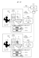
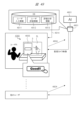
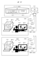
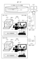
- a display system equipped with a display device receives video data of camera video, which is video captured by a camera, displays the camera video on a display screen based on the video data, selects a target camera, viewpoint, or subject from multiple cameras, multiple viewpoints, or camera subjects based on operational input by a user of the display device, receives video data of the camera video corresponding to the target camera, viewpoint, or subject in accordance with the selection, and displays the video on the display screen based on the received video data.
- the present invention makes it possible to realize a more suitable floating image display device.
- Other issues, configurations, and advantages will be made clear in the description of the embodiments below.
- 1 is a diagram showing an example of a usage form of a space floating image display device according to an embodiment of the present invention
- 1 is a diagram showing an example of a main part configuration and a retroreflection part configuration of a space floating image display device according to an embodiment of the present invention
- 1 is a diagram showing an example of a main part configuration and a retroreflection part configuration of a space floating image display device according to an embodiment of the present invention
- 1 is a diagram showing an example of a main part configuration and a retroreflection part configuration of a space floating image display device according to an embodiment of the present invention
- 1 is a diagram showing an example of a main part configuration and a retroreflection part configuration of a floating-in-the-air image display device according to an embodiment of the present invention
- 1 is a projection diagram of a retroreflector constituting a floating-in-the-air image display device according to an embodiment of the present invention
- FIG. 2 is a top view of a retroreflector constituting a floating-in-the-air image display device according to an embodiment of the present invention.
- FIG. 2 is a perspective view showing a corner reflector constituting a retroreflector constituting a floating-in-the-air image display device according to an embodiment of the present invention.
- FIG. 2 is a top view showing a corner reflector constituting a retroreflector constituting a floating-in-the-air image display device according to an embodiment of the present invention.
- 1 is a side view showing a corner reflector constituting a retroreflector constituting a floating-in-the-air image display device according to an embodiment of the present invention;
- FIG. 1 is a diagram showing a configuration example of a space floating image display device according to an embodiment of the present invention
- FIG. 1 is a diagram showing an example of a configuration of a space floating image display device according to an embodiment of the present invention.
- FIG. 1 is a diagram showing an example of a configuration of a space floating image display device according to an embodiment of the present invention.
- FIG. 1 is a diagram showing an example of a configuration of a space floating image display device according to an embodiment of the present invention.
- FIG. 1 is a diagram showing an example of a configuration of a space floating image display device according to an embodiment of the present invention.
- FIG. 1 is a diagram showing an example of a configuration of a space floating image display device according to an embodiment of the present invention.
- FIG. 1 is a diagram showing an example of a configuration of a space floating image display device according to an embodiment of the present invention.
- FIG. 1 is a diagram showing an example of a configuration of a space floating image display device according to an embodiment of the present invention.
- FIG. 1 is a diagram showing an example of a configuration of a space floating image display device according to an embodiment of the present invention.
- FIG. 1 is a diagram showing an example of a configuration of a space floating image display device according to an embodiment of the present invention.
- FIG. 1 is a diagram showing an example of a configuration of a space floating image display device according to an embodiment of the present invention.
- FIG. 1 is a diagram showing an example of a configuration of a space floating image display device according to an embodiment of the present invention.
- FIG. 1 is a diagram showing an example of a configuration of a space floating image display device according to an embodiment of the present invention.
- FIG. 1 is a diagram showing an example of a configuration of a space floating image display device according to an embodiment of the present invention.
- FIG. 1 is a diagram showing an example of a configuration of a space floating image display device according to an embodiment of the present invention.
- FIG. 1 is a diagram showing an example of a configuration of a space floating image display device according to an embodiment of the present invention.
- FIG. 1 is a diagram showing an example of a configuration of a space floating image display device according to an embodiment of the present invention.
- FIG. 1 is a diagram showing an example of a configuration of a space floating image display device according to an embodiment of the present invention.
- FIG. 2 is a cross-sectional view showing an example of a specific configuration of a light source device according to an embodiment of the present invention.
- FIG. 2 is a cross-sectional view showing an example of a specific configuration of a light source device according to an embodiment of the present invention.
- 1 is a layout diagram showing a main part of a space floating image display device according to an embodiment of the present invention; 1 is a cross-sectional view showing a configuration of a display device according to an embodiment of the present invention. 1 is a cross-sectional view showing a configuration of a display device according to an embodiment of the present invention. 1 is an explanatory diagram for explaining a light source diffusion characteristic of an image display device according to an embodiment of the present invention.
- FIG. 1 is an explanatory diagram for explaining the diffusion characteristics of a video display device according to an embodiment of the present invention
- 1 is a diagram illustrating an example of a problem to be solved by image processing according to an embodiment of the present invention
- FIG. 4 is an explanatory diagram of an example of image processing according to an embodiment of the present invention.
- FIG. 4 is an explanatory diagram of an example of a video display process according to an embodiment of the present invention.
- FIG. 4 is an explanatory diagram of an example of a video display process according to an embodiment of the present invention.
- FIG. 1 is a diagram showing an example of a main part configuration and a retroreflection part configuration of a space floating image display device according to an embodiment of the present invention
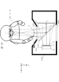
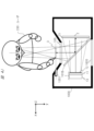
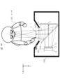
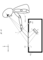
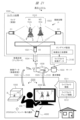
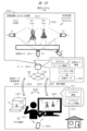
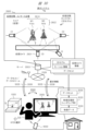
- 1 is an explanatory diagram of a display system including a space floating image display device according to an embodiment of the present invention
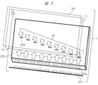
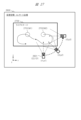
- FIG. 2 is an explanatory diagram of an example of a camera arrangement according to an embodiment of the present invention.
- FIG. 1 is an explanatory diagram of a configuration example of a space floating image display device according to an embodiment of the present invention
- 1 is an explanatory diagram of a configuration example of a space floating image display device according to an embodiment of the present invention
- 1 is an explanatory diagram of a configuration example of a space floating image display device according to an embodiment of the present invention
- 1 is an explanatory diagram of a configuration example of a space floating image display device according to an embodiment of the present invention
- 1 is an explanatory diagram of a configuration example of a space floating image display device according to an embodiment of the present invention
- FIG. 11 is an explanatory diagram of an example of control according to an embodiment of the present invention.
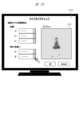
- FIG. 2 is an illustration of an example GUI according to one embodiment of the present invention.
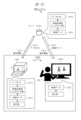
- FIG. 1 is an explanatory diagram of a configuration example of a display system according to an embodiment of the present invention.
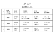
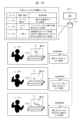
- FIG. 11 is an explanatory diagram of an example of a selection information table according to one embodiment of the present invention.
- FIG. 11 is an explanatory diagram of an example of a selection information table according to one embodiment of the present invention.
- FIG. 1 is an explanatory diagram illustrating an example of the configuration of a display device that is a television according to an embodiment of the present invention.
- FIG. 2 is an explanatory diagram of an example of a configuration of a server according to an embodiment of the present invention.
- FIG. 2 is an explanatory diagram relating to transmission and reception of data between a server and a display device according to an embodiment of the present invention.
- FIG. 1 is an explanatory diagram of a configuration example of a display system according to an embodiment of the present invention.
- FIG. 2 is an explanatory diagram of a virtual camera in a virtual space according to one embodiment of the present invention.
- FIG. 2 is an illustration of an example GUI according to one embodiment of the present invention.
- FIG. 10 is an explanatory diagram of an example of the configuration of an aerial operation detection sensor according to an embodiment of the present invention.
- FIG. 1 is an explanatory diagram of a configuration example of a display system according to an embodiment of the present invention.
- FIG. 10 is an explanatory diagram of motion information according to one embodiment of the present invention.
- FIG. 1 is an explanatory diagram of a configuration example of a display system according to an embodiment of the present invention.
- FIG. 1 is an explanatory diagram of a configuration example of a display system according to an embodiment of the present invention.
- FIG. 2 is an explanatory diagram of a specific example of data distribution according to an embodiment of the present invention.
- FIG. 2 is an explanatory diagram of data distribution in a display system according to one embodiment of the present invention.
- FIG. 2 is an explanatory diagram of data transmission by a sending system according to one embodiment of the present invention.
- FIG. 2 is an explanatory diagram of data reception by a receiving system according to one embodiment of the present invention.
- 1 is an explanatory diagram of a display system including a space floating image display device according to an embodiment of the present invention;
- FIG. 1 is an explanatory diagram of an example of use of a display system according to an embodiment of the present invention.
- FIG. 1 is an explanatory diagram of an example of use of a display system according to an embodiment of the present invention.
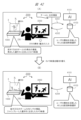
- FIG. 11 is an explanatory diagram of an example of camera video switching according to an embodiment of the present invention.
- FIG. 11 is an explanatory diagram of an example of camera image display ON/OFF according to an embodiment of the present invention.
- FIG. 1 is an explanatory diagram of an example configuration using AI in a display system according to an embodiment of the present invention.
- FIG. 11 is an explanatory diagram of an example of distribution video selection using AI according to one embodiment of the present invention.
- FIG. 11 is an explanatory diagram of an example of a distribution video selection that differs for each user using AI, according to one embodiment of the present invention.
- FIG. 11 is an explanatory diagram of an example of a GUI when using AI in accordance with one embodiment of the present invention.
- FIG. 11 is an explanatory diagram of an example of an evaluation input image when using AI in one embodiment of the present invention.
- FIG. 11 is an explanatory diagram of an example of an evaluation input image when AI is not used, according to one embodiment of the present invention.
- FIG. 11 is an explanatory diagram of an example of an evaluation input image when evaluating an AI selection in one embodiment of the present invention.
- FIG. 11 is an explanatory diagram of an example of the use of evaluation information according to one embodiment of the present invention.
- FIG. 11 is an explanatory diagram of an example of a GUI when using AI in accordance with one embodiment of the present invention.
- FIG. 11 is an explanatory diagram of an example of an evaluation input image when using AI in one embodiment of the present invention.
- FIG. 11 is an explanatory diagram of an example of an evaluation input image when AI is not used, according to one embodiment of the present invention.
- FIG. 11 is an explanatory diagram of an example of distribution video selection using AI in the case of on-demand distribution, in accordance with one embodiment of the present invention.
- FIG. 10 is an explanatory diagram of an example of using a video recorded on a recording medium according to an embodiment of the present invention.
- FIG. 1 is an explanatory diagram of an example of using AI and recorded video on a recording medium according to one embodiment of the present invention.
- the following examples relate to an image display device that can transmit an image produced by image light from an image emission source through a transparent member that divides a space, such as glass, and display the image as a floating image outside the transparent member.
- an image that floats in space is expressed using the term "floating image in space.” Instead of this term, it is also acceptable to express it as "aerial image,” “spatial image,” “floating image in space,” “floating optical image of displayed image,” “floating optical image of displayed image,” etc.
- the term “floating image in space” that is mainly used in the explanation of the examples is used as a representative example of these terms.
- a suitable image display device can be realized in a bank ATM, a ticket vending machine at a station, a digital signage, etc.
- a touch panel is usually used in a bank ATM, a ticket vending machine at a station, etc., but a transparent glass surface or a light-transmitting plate material can be used to display high-resolution image information in a floating state on the glass surface or the light-transmitting plate material.
- a device including the light source of this embodiment can provide a new and highly usable floating image display device (floating image display system) that can significantly reduce power consumption.
- a floating image display device for a vehicle that can display a floating image in a one-way manner, which is visible inside and/or outside the vehicle, can be provided.
- FIG. 1 is a diagram showing an example of the use of a space-floating image display device according to an embodiment of the present invention, and is a diagram showing the overall configuration of the space-floating image display device according to this embodiment. The specific configuration of the space-floating image display device will be described in detail using FIG.
- the retroreflector 2 (retroreflector) is used as an example of the retroreflector.
- the retroreflector 2 of the present invention is not limited to a flat plate, and is used as an example of a concept including a sheet-like retroreflector attached to a flat or non-flat member, and an entire assembly in which a sheet-like retroreflector is attached to a flat or non-flat member. Furthermore, since the light rays reflected by the retroreflector 2 have the optical property of forming an image, the retroreflector 2 may be expressed as an imaging optical member or an imaging optical plate.
- the space is divided by a show window (also called “window glass”) 105, which is a translucent material such as glass.
- a show window also called “window glass”
- the inside of the window glass 105 (inside the store) is shown in the depth direction, with the outside (e.g., the sidewalk) in the foreground.
- the window glass 105 by providing the window glass 105 with a means for reflecting a specific polarized wave, it is possible to reflect the wave and form an aerial image at a desired position inside the store.
- FIG. 2A is a diagram showing an example of the configuration of an optical system of a space floating image display device according to an embodiment of the present invention.
- the configuration of the space floating image display device will be described in more detail using FIG. 2A.
- a display device 1 that diverges specific polarized image light at a narrow angle is provided in the oblique direction of a transparent member 100 such as glass.
- the display device 1 includes a liquid crystal display panel 11 and a light source device 13 that generates specific polarized light having a narrow angle diffusion characteristic.
- the image light of a specific polarization from the display device 1 is reflected by the polarization separation member 101 (in the figure, the polarization separation member 101 is formed into a sheet and adhered to the transparent member 100) having a film that selectively reflects the image light of a specific polarization provided on the transparent member 100, and enters the retroreflector 2.
- a ⁇ /4 plate 21 is provided on the image light incidence surface of the retroreflector 2. The image light is made to pass through the ⁇ /4 plate 21 twice, when it enters the retroreflector 2 and when it leaves, and is polarized and converted from the specific polarization to the other polarization.
- the polarization separation member 101 that selectively reflects the image light of a specific polarization has the property of transmitting the polarized light of the other polarization that has been polarized and converted, so the image light of the specific polarization after polarization conversion passes through the polarization separation member 101.
- the image light that has passed through the polarization separation member 101 forms a real image, a floating image 3, outside the transparent member 100.
- FIG. 2A shows an example in which the chief ray of the image light incident on the retroreflector 2 is incident at 90° to the retroreflector 2.
- the incident angle of the chief ray of the image light on the retroreflector 2 is not limited to 90°, and can also be, for example, 90° ⁇ 15°.
- the image light converted to P-polarized light travels again toward the polarization separation member 101.
- the polarization separation member 101 has the property of reflecting S-polarized light and transmitting P-polarized light, so that the P-polarized image light passes through the polarization separation member 101 and then through the transparent member 100.
- the image light that passes through the transparent member 100 is generated by the retroreflector 2, so it forms a floating image 3, which is an optical image of the image displayed on the display device 1, at a position that is in a mirror relationship with the image displayed on the display device 1 relative to the polarization separation member 101.
- This polarization design makes it possible to form the floating image 3 in an optimal manner.
- the display device 1 may be configured to emit P-polarized image light to the polarization separation member 101, and the polarization separation member 101 may have the property of reflecting P-polarized light and transmitting S-polarized light.
- the P-polarized image light that reaches the polarization separation member 101 from the display device 1 is reflected by the polarization separation member 101 and travels toward the retroreflector 2.
- the image light is reflected by the retroreflector 2, it passes through the ⁇ /4 plate 21 provided on the incident surface of the retroreflector 2 twice, so that the image light is converted from P-polarized light to S-polarized light.
- the image light converted to S-polarized light travels again toward the polarization separation member 101.
- the polarization separation member 101 has the property of reflecting P-polarized light and transmitting S-polarized light, so the S-polarized image light passes through the polarization separation member 101 and then through the transparent member 100.
- the image light that passes through the transparent member 100 is generated by the retroreflector 2, so it forms a floating image 3, which is an optical image of the image displayed on the display device 1, at a position that is in a mirror relationship with the image displayed on the display device 1 relative to the polarization separation member 101.
- This polarization design makes it possible to form the floating image 3 in an optimal manner.
- the light that forms the floating image 3 is a collection of light rays that converge from the retroreflector 2 to the optical image of the floating image 3, and these light rays continue to travel in a straight line even after passing through the optical image of the floating image 3. Therefore, the floating image 3 is an image with high directionality, unlike the diffuse image light formed on a screen by a general projector or the like. Therefore, in the configuration of FIG. 2A, when a user views the floating image 3 from the direction of arrow A, the floating image 3 is seen as a bright image. However, when another person views the floating image 3 from the direction of arrow B, the floating image 3 cannot be seen as an image at all. This characteristic is very suitable for use in a system that displays images that require high security or highly confidential images that should be kept secret from people directly facing the user.
- the polarization axis of the reflected image light may become uneven.
- the reflection angle may also become uneven.
- Such uneven light may not maintain the polarization state and propagation angle assumed in the design.
- light with a polarization state and propagation angle that is not assumed in the design may re-enter the image display surface side of the liquid crystal display panel 11 directly from the position of the retroreflector 2 without passing through the polarization separation member.
- Such light with a polarization state and propagation angle that is not assumed in the design may be reflected by a component in the space floating image display device and then re-enter the image display surface side of the liquid crystal display panel 11.
- Such light that re-enters the image display surface side of the liquid crystal display panel 11 may be re-reflected by the image display surface of the liquid crystal display panel 11 that constitutes the display device 1, generating a ghost image and possibly degrading the image quality of the space floating image. Therefore, in this embodiment, an absorbing polarizing plate 12 may be provided on the image display surface of the display device 1.
- the image light emitted from the display device 1 is transmitted through the absorptive polarizer 12, and the reflected light returning from the polarization separation member 101 is absorbed by the absorptive polarizer 12, thereby suppressing the re-reflection. This makes it possible to prevent degradation of image quality due to ghost images of spatially floating images.
- the absorptive polarizer 12 may be a polarizer that absorbs P-polarized light. Also, if the display device 1 is configured to emit P-polarized image light to the polarization separation member 101, the absorptive polarizer 12 may be a polarizer that absorbs S-polarized light.
- the above-mentioned polarization separation member 101 may be formed, for example, from a reflective polarizing plate or a metal multilayer film that reflects a specific polarized wave.
- FIG. 2A (2) shows an example of the surface shape of a typical retroreflector 2.
- Light rays incident on the interior of regularly-arranged hexagonal prisms are reflected by the walls and bottoms of the hexagonal prisms and emitted as retroreflected light in a direction corresponding to the incident light, and a real image floating in space is displayed based on the image displayed on the display device 1.
- the resolution of this floating image in space depends not only on the resolution of the liquid crystal display panel 11, but also on the outer shape D and pitch P of the retroreflective portion of the retroreflector 2 shown in Figure 2A (2).
- the resolution of the floating image in space depends not only on the resolution of the liquid crystal display panel 11, but also on the outer shape D and pitch P of the retroreflective portion of the retroreflector 2 shown in Figure 2A (2).
- the resolution of the floating image in space depends not only on the resolution of the liquid crystal display panel 11, but also on the outer shape D and pitch P of the retroreflective portion of the retroreflector 2 shown in Figure 2A (2).
- the resolution of the floating image in space will be reduced to about 1/3.
- the diameter and pitch of the retroreflective portion close to that of one pixel of the liquid crystal display panel.
- the pitch ratio of each it is advisable to design the pitch ratio of each to be a different integer multiple of one pixel.
- the surface shape of the retroreflector of this embodiment is not limited to the above example. It may have various surface shapes that realize retroreflection. Specifically, the surface of the retroreflector of this embodiment may be provided with retroreflection elements in which triangular pyramid prisms, hexagonal pyramid prisms, other polygonal prisms, or combinations of these are periodically arranged. Alternatively, the surface of the retroreflector of this embodiment may be provided with retroreflection elements in which these prisms are periodically arranged to form cube corners. These can also be expressed as corner reflector arrays and multifaceted reflector arrays. Alternatively, the surface of the retroreflector of this embodiment may be provided with capsule lens-type retroreflection elements in which glass beads are periodically arranged.
- the transparent member may be formed of a metal multilayer film that selectively transmits a specific polarization and reflects the polarization of other specific polarizations.
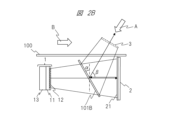
- the polarization separation member 101B is configured to transmit the image light of a specific polarization output from the display device 1.
- the image light that has passed through the polarization separation member 101B enters the retroreflector 2.
- a ⁇ /4 plate 21 is provided on the image light incident surface of the retroreflector.
- the image light is polarized and converted from a specific polarization to the other polarization by passing through the ⁇ /4 plate 21 twice, when it enters the retroreflector and when it leaves.
- the polarization separation member 101B has the property of reflecting the polarized light of the other polarization that has been polarized and converted by the ⁇ /4 plate 21, so the image light after polarization conversion is reflected by the polarization separation member 101B.
- the image light reflected by the polarization separation member 101B passes through the transparent member 100 and forms a spatially floating image 3, which is a real image, outside the transparent member 100.
- the image light converted to P-polarized light heads again toward the polarization separation member 101B.
- the polarization separation member 101B has the property of reflecting P-polarized light and transmitting S-polarized light, so that the P-polarized image light is reflected by the polarization separation member 101 and passes through the transparent member 100.
- the image light that passes through the transparent member 100 is generated by the retroreflector 2, so it forms a floating image 3, which is an optical image of the image displayed on the display device 1, at a position that is in a mirror relationship with the image displayed on the display device 1 relative to the polarization separation member 101B.
- This polarization design allows the floating image 3 to be formed optimally.
- the optical system of FIG. 2B is an optical system with a different configuration from the optical system of FIG. 2A, but can form a suitable floating image in space, just like the optical system of FIG. 2A.
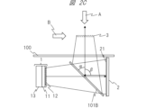
- the only difference between the optical system in FIG. 2B and the optical system in FIG. 2C is the angle at which the polarization separation member 101B is disposed relative to the image display surface of the display device 1 and the surface of the retroreflector 2. All other configurations are similar to the optical system in FIG. 2B, so a repeated description will be omitted.
- the polarization design of the optical system in FIG. 2C is also similar to the polarization design of the optical system in FIG. 2B, so a repeated description will be omitted.
- the polarization separation member 101B is arranged at an angle ⁇ with respect to the image display surface of the display device 1 and the surface of the retroreflector 2.
- the angle ⁇ is 45°.
- the angle ⁇ between the traveling direction of the image light reflected by the polarization separation member 101B (direction of the chief ray of the image light) and the traveling direction of the image light incident from the retroreflector 2 is 90°.
- the image display surface of the display device 1 and the surface of the retroreflector 2 are perpendicular to the traveling direction of the image light reflected by the polarization separation member 101B, and the angular relationship of the surfaces constituting the optical system can be simplified. If the surface of the transparent member 100 is arranged so as to be perpendicular to the traveling direction of the image light reflected by the polarization separation member 101B, the angular relationship of the surfaces constituting the optical system can be further simplified.
- FIG. 2C when a user views the image from the direction of arrow A, the floating image 3 is perceived as a bright image. However, when another person views the image from the direction of arrow B, the floating image 3 cannot be seen as an image at all. This characteristic is very suitable for use in a system that displays images that require high security or highly confidential images that should be concealed from people directly facing the user.
- FIG. 2D Another example of the configuration of the optical system of the space floating image display device will be described with reference to FIG. 2D.
- the optical system of FIG. 2D is an optical system using a retroreflector 5 different from the retroreflector 2 used in FIG. 2A to FIG. 2C.
- Another example of the configuration 3 of the optical system will be described in more detail below with reference to FIG. 2D to FIG. 2I.
- the components with the same reference numerals as those in FIG. 2A to FIG. 2C have the same functions and configurations as those in FIG. 2A to FIG. 2C. Such components will not be described repeatedly in order to simplify the explanation.
- FIG. 2D is a diagram showing an example of the main components and retroreflective components of a spatial floating image display device according to one embodiment of the present invention.
- a display device 10 that emits image light is provided in an oblique direction of a transparent member 100 such as glass.
- the display device 10 includes a liquid crystal display panel 11 and a light source device 13 that generates light.
- the chief ray 9020 which represents the light beam emitted from the display device 10, travels toward the retroreflector 5 and is incident on the retroreflector 5 at an incident angle ⁇ .
- the incident angle ⁇ may be, for example, 45°.
- the incident angle ⁇ is not limited to 45°, and may be, for example, 45° ⁇ 15°.
- the retroreflector 5 is an optical element that has the optical property of retroreflecting light rays in at least some directions.
- the retroreflector 5 may also be referred to as an imaging optical element or imaging optical plate.
- the retroreflector 5 causes the main ray 9020 to travel in the z direction while being retroreflected in the x and y directions.
- the reflected ray 9021 travels along an optical path that is mirror-symmetrical to the main ray 9020 with the retroreflector 5 as the reference, in a direction away from the retroreflector 5, passes through the transparent member 100, and forms the floating-in-space image 3 as a real image on the imaging plane.
- the light beam that forms the floating image 3 is a collection of light rays that converge from the retroreflector 5 to the optical image of the floating image 3, and these light rays continue to travel in a straight line even after passing through the optical image of the floating image 3. Therefore, the floating image 3 is an image with high directionality, unlike a diffuse image formed on a screen by a general projector or the like. Therefore, in the configuration of Figure 2, when a user views the floating image 3 from the direction of arrow A, the floating image 3 is seen as a bright image. However, when another person views the floating image 3 from the direction of arrow B, the floating image 3 cannot be seen as an image at all. This characteristic is suitable for use in a system that displays images that require high security or highly confidential images that should be kept secret from people directly facing the user.
- the retroreflector 5 is configured by arranging multiple corner reflectors 9040 in an array on the surface of a transparent member 50. This may be called a corner reflector array or a multi-surface reflector array.
- the specific configuration of the corner reflector 9040 will be described in detail using Figures 2G, 2H, and 2I.
- Light rays 9111, 9112, 9113, and 9114 emitted from a light source 9110 are reflected twice by two mirror surfaces 9041 and 9042 of the corner reflector 9040, becoming reflected light rays 9121, 9122, 9123, and 9124.
- This double reflection is a retroreflection that turns back in the same direction as the incident direction (travels in a direction rotated 180 degrees) in the x and y directions, and a regular reflection in which the incident angle and reflection angle match due to total reflection in the z direction.
- the light rays 9111 to 9114 generate reflected light rays 9121 to 9124 on a straight line symmetrical in the z direction with respect to the corner reflector 9040, forming an aerial real image 9120.
- the light rays 9111 to 9114 emitted from the light source 9110 are four light rays that represent the diffused light from the light source 9110, and although the light rays that enter the retroreflector 5 are not limited to these depending on the diffusion characteristics of the light source 9110, all of the incident light rays cause similar reflections and form an aerial real image 9120.
- the position of the light source 9110 and the position of the aerial real image 9120 in the x direction are shifted, but in reality the position of the light source 9110 and the position of the aerial real image 9120 in the x direction are the same, and are overlapping when viewed from the z direction.
- the corner reflector 9040 is a rectangular parallelepiped with only two specific faces being mirror surfaces 9041 and 9042, and the other four faces being made of transparent material.
- the retroreflector 5 has a configuration in which the corner reflectors 9040 are arrayed so that the corresponding mirror surfaces face in the same direction.
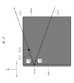
- mirror surface 9041 When viewed from the top (+z direction), light ray 9111 emitted from light source 9110 is incident on mirror surface 9041 (or mirror surface 9042) at a specific angle of incidence, is totally reflected at reflection point 9130, and is then totally reflected again at reflection point 9132 on mirror surface 9042 (or mirror surface 9041).
- the angle of incidence of light ray 9111 with respect to mirror surface 9041 (or mirror surface 9042) is ⁇
- the angle of incidence of the first reflected light ray 9131 reflected by mirror surface 9041 (or mirror surface 9042) with respect to mirror surface 9042 (or mirror surface 9041) can be expressed as 90°- ⁇ . Therefore, with respect to light ray 9111, the second reflected light ray 9121 rotates by 2 ⁇ after the first reflection and by 2 ⁇ (90°- ⁇ ) after the second reflection, resulting in a total inversion optical path of 180°.
- total reflection in the z direction occurs only once. Therefore, if the angle of incidence with respect to mirror surface 9041 or mirror surface 9042 is ⁇ , the reflected light ray 9121 rotates by 2 ⁇ after one reflection with respect to light ray 9111.
- the light rays incident on the corner reflector 9040 undergo retroreflection with inverted optical paths in the x and y directions, and undergo regular reflection due to total reflection in the z direction.
- the retroreflector 5 Similar reflections occur in each optical path, so that an image is formed at a point symmetrical with respect to the z-axis direction due to the inverted optical paths that are convergent in the x and y directions.
- the retroreflector 2 has retroreflection properties in three axial directions.
- the convergent reflected light beam travels towards the side of the retroreflector 2 where the light source of the incident light is located.
- This convergent reflected light beam forms an image in the air to form a floating image 3.
- the traveling direction of the chief ray of the convergent reflected light beam reflected from the retroreflector 2 is the opposite direction to the traveling direction of the chief ray of the diffusive incident light beam that is incident on the retroreflector 2.
- the retroreflector 5 has retroreflection properties in two axial directions, and is specular in the other axial direction.
- the retroreflector 5 when a diffusive incident light beam is incident on the retroreflector 5, the convergent reflected light beam reflected by the corner reflector array travels toward the side of the retroreflector 5 opposite the side where the light source of the incident light is located. This convergent reflected light beam forms an image in the air, forming the floating image 3.
- the direction of travel of the chief ray of the convergent reflected light beam reflected by the corner reflector array of the retroreflector 5 is not the opposite direction to the direction of travel of the chief ray of the diffusive incident light beam incident on the retroreflector 5.
- the normal component of the plate-shaped surface of the retroreflector 5 in the direction of travel of the chief ray of the diffusive incident light beam incident on the retroreflector 5 and the normal component of the plate-shaped surface of the retroreflector 5 in the direction of travel of the chief ray after being reflected by the retroreflector 5 to become a convergent reflected light beam continue to travel in a straight line before and after reflection by the corner reflector array.
- the diffusive incident light beam is converted into a convergent reflected light beam by reflection on the retroreflector 5, but in the normal direction to the plate-shaped surface of the retroreflector 5, this light beam travels as if passing through the retroreflector 5.
- the diffusive incident light beam that enters the retroreflector 5 and the convergent reflected light beam that exits from the retroreflector 5 are geometrically symmetrical with respect to the plate-shaped surface of the retroreflector 5.
- the resolution of the floating image formed by the light from the video output unit 10 depends heavily on the diameter D and pitch P (not shown) of the retroreflective portion of the retroreflector 5 shown in Figures 2E and 2F, in addition to the resolution of the liquid crystal display panel 11.
- D and pitch P not shown
- the diameter D of the retroreflective portion is 240 ⁇ m and the pitch P is 300 ⁇ m
- one pixel of the floating image in space will be equivalent to 300 ⁇ m.
- the effective resolution of the floating image in space will be reduced to about 1/3.
- the diameter D and pitch P of the retroreflective portion close to one pixel of the liquid crystal display panel.
- the pitch ratio of each it is advisable to design the pitch ratio of each to be a different integer multiple of one pixel.
- the shape of the retroreflector (imaging optical plate) according to this embodiment is not limited to the above example. It may have various shapes that realize retroreflection. Specifically, it may be various cubic corner bodies, corner reflector arrays, slit mirror arrays, two-sided corner reflector arrays, polyhedral reflector arrays, or shapes in which a combination of their reflective surfaces is periodically arranged. Alternatively, a capsule lens type retroreflection element in which glass beads are periodically arranged may be provided on the surface of the retroreflection plate of this embodiment. The detailed configuration of these retroreflection elements can be achieved by using existing technology, so a detailed description will be omitted. Specifically, it is possible to use the technology disclosed in JP2017-33005A, JP2019-133110A, JP2017-67933A, WO2009/131128A, etc.
- the image light emitted from the display device 10 can be in any polarization state. It does not matter whether it is S-polarized or P-polarized.
- the optical system of FIG. 2D is an optical system that uses a different retroreflector than the optical systems of FIG. 2A to FIG. 2C, but it can form a more suitable floating image in space, just like the optical systems of FIG. 2A to FIG. 2C.
- optical systems of Figures 2A, 2B, 2C, and 2D described above can provide brighter, higher quality floating images.
- Figure 3 is a block diagram showing an example of the internal configuration of the space floating image display device 1000.
- the floating-in-space image display device 1000 includes a retroreflection unit 1101, an image display unit 1102, a light guide 1104, a light source 1105, a power source 1106, an external power source input interface 1111, an operation input unit 1107, a non-volatile memory 1108, a memory 1109, a control unit 1110, an image signal input unit 1131, an audio signal input unit 1133, a communication unit 1132, an aerial operation detection sensor 1351, an aerial operation detection unit 1350, an audio output unit 1140, a microphone 1139, an image control unit 1160, a storage unit 1170, an imaging unit 1180, and the like. It may also include a removable media interface 1134, an attitude sensor 1113, a transmissive self-luminous image display device 1650, a second display device 1680, or a secondary battery 1112.
- the components of the space floating image display device 1000 are arranged in a housing 1190.
- the imaging unit 1180 and the aerial operation detection sensor 1351 shown in FIG. 3 may be provided on the outside of the housing 1190.
- the retroreflective portion 1101 in FIG. 3 corresponds to the retroreflective plate 2 in FIG. 2A, FIG. 2B, and FIG. 2C.
- the retroreflective portion 1101 retroreflects light modulated by the image display portion 1102.
- the light reflected from the retroreflective portion 1101 is output to the outside of the space-floating image display device 1000 to form the space-floating image 3.
- the image display unit 1102 in FIG. 3 corresponds to the liquid crystal display panel 11 in FIG. 2A, FIG. 2B, and FIG. 2C.
- the light source 1105 in FIG. 3 corresponds to the light source device 13 in FIG. 2A, FIG. 2B, and FIG. 2C.
- the image display unit 1102, the light guide 1104, and the light source 1105 in FIG. 3 correspond to the display device 1 in FIG. 2A, FIG. 2B, and FIG. 2C.
- the video display unit 1102 is a display unit that generates an image by modulating transmitted light based on a video signal input under the control of the video control unit 1160 described below.
- the video display unit 1102 corresponds to the liquid crystal display panel 11 of Figures 2A, 2B, and 2C.
- a transmissive liquid crystal panel is used as the video display unit 1102.
- a reflective liquid crystal panel that modulates reflected light or a DMD (Digital Micromirror Device: registered trademark) panel may be used as the video display unit 1102.
- the light source 1105 generates light for the image display unit 1102 and is a solid-state light source such as an LED light source or a laser light source.
- the power source 1106 converts AC current input from the outside via the external power input interface 1111 into DC current and supplies power to the light source 1105.
- the power source 1106 also supplies the necessary DC current to each part in the space-floating image display device 1000.
- the secondary battery 1112 stores the power supplied from the power source 1106.
- the secondary battery 1112 also supplies power to the light source 1105 and other components that require power when power is not supplied from the outside via the external power input interface 1111. In other words, when the space-floating image display device 1000 is equipped with the secondary battery 1112, the user can use the space-floating image display device 1000 even when power is not supplied from the outside.
- the light guide 1104 guides the light generated by the light source 1105 and irradiates it onto the image display unit 1102.
- the combination of the light guide 1104 and the light source 1105 can also be called the backlight of the image display unit 1102.
- the light guide 1104 may be configured mainly using glass.
- the light guide 1104 may be configured mainly using plastic.
- the light guide 1104 may be configured using a mirror. There are various methods for combining the light guide 1104 and the light source 1105. Specific configuration examples for the combination of the light guide 1104 and the light source 1105 will be explained in detail later.
- the aerial operation detection sensor 1351 is a sensor that detects the operation of the floating-in-space image 3 by the finger of the user 230.
- the aerial operation detection sensor 1351 senses, for example, a range that overlaps with the entire display range of the floating-in-space image 3. Note that the aerial operation detection sensor 1351 may only sense a range that overlaps with at least a portion of the display range of the floating-in-space image 3.
- the aerial operation detection sensor 1351 include a distance sensor that uses invisible light such as infrared rays, an invisible light laser, ultrasonic waves, etc.
- the aerial operation detection sensor 1351 may also be configured to detect coordinates on a two-dimensional plane by combining multiple sensors.
- the aerial operation detection sensor 1351 may also be configured with a ToF (Time of Flight) type LiDAR (Light Detection and Ranging) or an image sensor.
- ToF Time of Flight
- LiDAR Light Detection and Ranging
- the mid-air operation detection sensor 1351 only needs to be capable of sensing to detect touch operations, etc., performed by the user with his/her finger on an object displayed as the floating-in-space image 3. Such sensing can be performed using existing technology.
- the aerial operation detection unit 1350 acquires a sensing signal from the aerial operation detection sensor 1351, and performs operations such as determining whether or not the finger of the user 230 has touched an object in the floating-in-space image 3 and calculating the position (contact position) at which the finger of the user 230 has touched the object based on the sensing signal.
- the aerial operation detection unit 1350 is configured with a circuit such as an FPGA (Field Programmable Gate Array). Some of the functions of the aerial operation detection unit 1350 may also be realized by software, for example, by a spatial operation detection program executed by the control unit 1110.
- the aerial operation detection sensor 1351 and the aerial operation detection unit 1350 may be configured to be built into the space-floating image display device 1000, or may be provided separately from the space-floating image display device 1000. When provided separately from the space-floating image display device 1000, the aerial operation detection sensor 1351 and the aerial operation detection unit 1350 are configured to transmit information and signals to the space-floating image display device 1000 via a wired or wireless communication connection path or image signal transmission path.
- the aerial operation detection sensor 1351 and the aerial operation detection unit 1350 may be provided separately. This makes it possible to build a system in which the air-floating image display device 1000, which does not have an aerial operation detection function, is the main body, and only the aerial operation detection function can be added as an option. Also, a configuration in which only the aerial operation detection sensor 1351 is a separate unit, and the aerial operation detection unit 1350 is built into the air-floating image display device 1000, may be used. In cases where it is desired to more freely position the aerial operation detection sensor 1351 relative to the installation position of the air-floating image display device 1000, a configuration in which only the aerial operation detection sensor 1351 is a separate unit is advantageous.
- the imaging unit 1180 is a camera with an image sensor, and captures the space near the floating-in-space image 3 and/or the face, arms, fingers, etc. of the user 230.
- a plurality of imaging units 1180 may be provided. By using a plurality of imaging units 1180, or by using an imaging unit with a depth sensor, it is possible to assist the aerial operation detection unit 1350 in detecting the touch operation of the floating-in-space image 3 by the user 230.
- the imaging unit 1180 may be provided separately from the floating-in-space image display device 1000. When the imaging unit 1180 is provided separately from the floating-in-space image display device 1000, it is sufficient to configure it so that an imaging signal can be transmitted to the floating-in-space image display device 1000 via a wired or wireless communication connection path, etc.
- the distance between the object and the intrusion detection plane can be calculated by using information such as object depth calculation information based on the captured images of the multiple image capturing units 1180 and object depth information from the depth sensor.
- This information, as well as various other information such as the distance between the object and the intrusion detection plane, are used for various display controls for the floating in space image 3.
- the video data, image data, etc. recorded in the storage unit 1170 are output as the space floating image 3 via the image display unit 1102 and the retroreflective unit 1101.
- the video data, image data, etc. of the display icons and objects for the user to operate, which are displayed as the space floating image 3, are also recorded in the storage unit 1170.
- the image control unit 1160 may also generate a superimposed image signal by superimposing the image signal to be stored in the memory 1109 and the image signal input from the image signal input unit 1131, and input the superimposed image signal to the image display unit 1102, thereby controlling the formation of a composite image as a floating-in-space image 3.
- the video control unit 1160 may also control image processing of the video signal input from the video signal input unit 1131 and the video signal to be stored in the memory 1109.
- image processing include scaling processing to enlarge, reduce, or deform an image, brightness adjustment processing to change the brightness, contrast adjustment processing to change the contrast curve of an image, and Retinex processing to break down an image into light components and change the weighting of each component.
- the video control unit 1160 may also perform special effect video processing, etc., to assist the user 230 in performing an aerial operation (touch operation) on the video signal input to the video display unit 1102.
- the special effect video processing is performed, for example, based on the detection result of the touch operation of the user 230 by the aerial operation detection unit 1350, or on an image of the user 230 captured by the imaging unit 1180.
- the attitude sensor 1113 is a sensor consisting of a gravity sensor or an acceleration sensor, or a combination of these, and can detect the attitude in which the space-floating image display device 1000 is installed. Based on the attitude detection result of the attitude sensor 1113, the control unit 1110 may control the operation of each connected unit. For example, if an undesirable attitude is detected as the user's usage state, control may be performed to stop the display of the image being displayed on the image display unit 1102 and display an error message to the user. Alternatively, if the attitude sensor 1113 detects that the installation attitude of the space-floating image display device 1000 has changed, control may be performed to rotate the display direction of the image being displayed on the image display unit 1102.
- the space-floating image display device 1000 is equipped with various functions. However, the space-floating image display device 1000 does not need to have all of these functions, and any configuration is acceptable as long as it has the function of forming the space-floating image 3.
- FIG. 4A is a diagram showing an example of the configuration of a space-floating image display device.
- the space-floating image display device 1000 shown in FIG. 4A is equipped with an optical system corresponding to the optical system of FIG. 2A.
- the space-floating image display device 1000 shown in FIG. 4A is installed horizontally so that the surface on which the space-floating image 3 is formed faces upward. That is, in FIG. 4A, the space-floating image display device 1000 has a transparent member 100 installed on the top surface of the device.
- the space-floating image 3 is formed above the surface of the transparent member 100 of the space-floating image display device 1000.
- the light of the space-floating image 3 travels diagonally upward.
- the mid-air operation detection sensor 1351 When the mid-air operation detection sensor 1351 is provided as shown in the figure, it is possible to detect the operation of the space-floating image 3 by the finger of the user 230.
- the x direction is the left-right direction as seen from the user
- the y direction is the front-back direction (depth direction) as seen from the user
- the z direction is the up-down direction (vertical direction).
- the definitions of the x-direction, y-direction, and z-direction are the same in each of the figures in Figure 4, so repeated explanations will be omitted.
- the light of the space-floating image 3 travels diagonally upward.
- the midair operation detection sensor 1351 is provided as shown in the figure, it is possible to detect the operation of the space-floating image 3 by the finger of the user 230.
- the aerial operation detection sensor 1351 senses the finger of the user 230 from above, and can use the reflection of sensing light by the user's nail for touch detection.
- the nail has a higher reflectivity than the pad of the finger, so this configuration can improve the accuracy of touch detection.
- FIG. 4C is a diagram showing an example of the configuration of a space-floating image display device.
- the space-floating image display device 1000 shown in FIG. 4C is equipped with an optical system corresponding to the optical system of FIG. 2B.
- the space-floating image display device 1000 shown in FIG. 4C is installed horizontally so that the surface on which the space-floating image 3 is formed faces upward. That is, in FIG. 4C, the space-floating image display device 1000 has a transparent member 100 installed on the top surface of the device.
- the space-floating image 3 is formed above the surface of the transparent member 100 of the space-floating image display device 1000.
- the light of the space-floating image 3 travels diagonally upward. If the mid-air operation detection sensor 1351 is provided as shown in the figure, it can detect the operation of the space-floating image 3 by the finger of the user 230.
- FIG. 4D is a diagram showing an example of the configuration of a space-floating image display device.
- the space-floating image display device 1000 shown in FIG. 4D is equipped with an optical system corresponding to the optical system of FIG. 2B.
- the space-floating image display device 1000 shown in FIG. 4D is installed vertically so that the surface on which the space-floating image 3 is formed faces the front of the space-floating image display device 1000 (toward the user 230). That is, in FIG. 4D, the space-floating image display device 1000 is installed with the transparent member 100 on the front side of the device (toward the user 230).
- the space-floating image 3 is formed on the user 230 side with respect to the surface of the transparent member 100 of the space-floating image display device 1000.
- FIG. 4E is a diagram showing an example of the configuration of a floating-in-space image display device.
- the floating-in-space image display device 1000 shown in FIG. 4E is equipped with an optical system corresponding to the optical system in FIG. 2C.
- the floating-in-space image display device 1000 shown in FIG. 4E is installed horizontally so that the surface on which the floating-in-space image 3 is formed faces upward. That is, in FIG. 4E, the floating-in-space image display device 1000 has a transparent member 100 installed on the top surface of the device.
- the floating-in-space image 3 is formed above the surface of the transparent member 100 of the floating-in-space image display device 1000.
- the light of the floating-in-space image 3 travels directly upward. If the mid-air operation detection sensor 1351 is provided as shown in the figure, it is possible to detect the operation of the floating-in-space image 3 by the finger of the user 230.
- FIG. 4F is a diagram showing an example of the configuration of a space-floating image display device.
- the space-floating image display device 1000 shown in FIG. 4F is equipped with an optical system corresponding to the optical system of FIG. 2C.
- the space-floating image display device 1000 shown in FIG. 4F is installed vertically so that the surface on which the space-floating image 3 is formed faces the front of the space-floating image display device 1000 (toward the user 230). That is, in FIG. 4F, the space-floating image display device 1000 is installed with the transparent member 100 on the front side of the device (toward the user 230).
- the space-floating image 3 is formed on the user 230 side with respect to the surface of the transparent member 100 of the space-floating image display device 1000.
- the light of the space-floating image 3 travels in the direction toward the user. If the mid-air operation detection sensor 1351 is provided as shown in the figure, it is possible to detect the operation of the space-floating image 3 by the finger of the
- FIG. 4G is a diagram showing an example of the configuration of a space-floating image display device.
- the space-floating image display device 1000 shown in FIG. 4G is equipped with an optical system corresponding to the optical system of FIG. 2C.
- the central optical path of the image light emitted from the display device 1 was on the yz plane. That is, in the optical systems of the space-floating image display devices shown in FIG. 4A to FIG. 4F, the image light traveled in the front-back direction and the up-down direction as seen from the user.
- the central optical path of the image light emitted from the display device 1 is on the xy plane. That is, in the optical system of the space-floating image display device shown in FIG. 4G, the image light travels in the left-right direction and the front-back direction as seen from the user.
- the surface on the side on which the space-floating image 3 is formed is installed so that it faces the front of the device (the direction of the user 230). That is, in FIG. 4G, the space-floating image display device 1000 has the transparent member 100 installed on the front side of the device (toward the user 230).
- the space-floating image 3 is formed on the user side of the surface of the transparent member 100 of the space-floating image display device 1000.
- the light of the space-floating image 3 travels toward the user. If the mid-air operation detection sensor 1351 is provided as shown in the figure, it can detect the operation of the space-floating image 3 by the finger of the user 230.
- FIG. 4H is a diagram showing an example of the configuration of a space-floating image display device.
- the space-floating image display device 1000 of FIG. 4H differs from the space-floating image display device of FIG. 4G in that it has a window having a transparent plate 100B such as glass or plastic on the back of the device (opposite the position where the user 230 views the space-floating image 3, i.e., opposite the traveling direction of the image light of the space-floating image 3 toward the user 230).
- the other configurations are the same as those of the space-floating image display device of FIG. 4G, so repeated explanations will be omitted.
- the 4H has a window having a transparent plate 100B at a position opposite the traveling direction of the image light of the space-floating image 3 with respect to the space-floating image 3. Therefore, when the user 230 views the space-floating image 3, the scenery behind the space-floating image display device 1000 can be recognized as the background of the space-floating image 3. Therefore, the user 230 can perceive the space floating image 3 as floating in the air in front of the scenery behind the space floating image display device 1000. This further emphasizes the feeling of floating in the air of the space floating image 3.
- the window on the back of the space floating image display device 1000 may be configured without providing the transparent plate 100B.
- FIG. 4I is a diagram showing an example of the configuration of a space-floating image display device.
- the space-floating image display device 1000 in FIG. 4I differs from the space-floating image display device in FIG. 4H in that a light-blocking door 1410 is provided in the window of the transparent plate 100B located on the back of the device (the opposite side to the position where the user 230 views the space-floating image 3).
- the rest of the configuration is the same as that of the space-floating image display device in FIG. 4H, so repeated explanations will be omitted.
- the control unit 1110 may control a motor (not shown) to perform a shielding operation by the light shielding plate of the opening and closing door 1410.
- the above-mentioned opening and closing door 1410 may be provided on the window that does not have the transparent plate 100B. In order to prevent this stray light, it is desirable that the surface of the light shielding plate of the above-mentioned opening and closing door 1410 on the inside of the housing has a coating or material with low light reflectance.
- FIG. 4J is a diagram showing an example of the configuration of a space-floating image display device.
- the space-floating image display device 1000 of FIG. 4J differs from the space-floating image display device of FIG. 4H in that instead of placing a transparent plate 100B made of glass or plastic on the rear side window, an electronically controlled transmittance variable device 1620 is placed.
- the rest of the configuration is the same as that of the space-floating image display device of FIG. 4H, so repeated explanations will be omitted.
- An example of the electronically controlled transmittance variable device 1620 is a liquid crystal shutter, etc.
- the liquid crystal shutter can control the transmitted light by controlling the voltage of the liquid crystal element sandwiched between two polarizing plates. Therefore, if the liquid crystal shutter is controlled to increase the transmittance, the scenery through the rear window can be seen through the background of the floating image 3. Also, if the liquid crystal shutter is controlled to increase the transmittance, the scenery through the rear window can be hidden as the background of the floating image 3. In addition, since the liquid crystal shutter can control the intermediate length, it can also be set to a state of transmittance of 50% or the like.
- the control unit 1110 may control the transmittance of the electronically controlled transmittance variable device 1620 in response to an operation input via the operation input unit 1107 in FIG. 3.
- the control unit 1110 in FIG. 3 controls the transmittance of the electronically controlled transmittance variable device 1620 according to the detection result of the illuminance sensor.
- the transmittance of the electronically controlled transmittance variable device 1620 can be adjusted according to the brightness of the space beyond the rear window even if the user 230 does not perform operation input via the operation input unit 1107 in FIG. 3, making it possible to more appropriately maintain the visibility of the space floating image 3.
- a liquid crystal shutter has been described as an example of the electronically controlled transmittance variable device 1620.
- electronic paper may be used as another example of the electronically controlled transmittance variable device 1620.
- the same effect as described above can be obtained when electronic paper is used.
- electronic paper consumes very little power to maintain a halftone state. Therefore, a low-power floating image display device can be realized compared to the case where a liquid crystal shutter is used.
- FIG. 4K is a diagram showing an example of the configuration of a space-floating image display device.
- the space-floating image display device 1000 of FIG. 4K differs from the space-floating image display device of FIG. 4G in that it has a transmissive self-luminous image display device 1650 instead of a transparent member 100.
- the rest of the configuration is the same as that of the space-floating image display device of FIG. 4G, so repeated explanations will be omitted.
- an absorbing polarizing plate (not shown) that transmits the polarized wave of the image light reflected by the polarization separation member 101B and absorbs the polarized wave that is 90 degrees out of phase with the polarized wave may be provided on the inner surface of the transmissive self-luminous image display device 1650 (the incident surface of the image light reflected by the polarization separation member 101B to the transmissive self-luminous image display device 1650, i.e., the surface of the transmissive self-luminous image display device 1650 opposite the space-floating image 3).
- a portion of the image light output from the display device 1 may be reflected by the polarization separation member 101B and travel toward the second display device 1680.
- This light (a portion of the image light) may be reflected again by the surface of the second display device 1680 and may be visually recognized by the user as stray light.
- the second display device 1680 displays both the background and an object such as a character, and then the object such as the character moves into the floating-in-space image 3 in the foreground, it is possible to provide the user 230 with a more effective surprise video experience.
- FIG. 4N is a diagram showing an example of the configuration of a space-floating image display device.
- the space-floating image display device 1000 in FIG. 4N is a space-floating image display device that employs the optical system in FIG. 2D.
- an image is formed in the air as a space-floating image 3 by image light that has passed through a transparent member 100.
- the operation of the space-floating image 3 by the user's finger 9004 can be detected using the sensing light of an aerial operation detection sensor 1351 that is positioned on the back side of the transparent member 100 as seen from the user.
- the floating-in-space image 3 is formed in front of the transparent member 100, and the operation of the floating-in-space image 3 by the user's finger can be detected using the sensing light of the aerial operation detection sensor 1351 arranged on the back side of the transparent member 100 as seen by the user. Therefore, the floating-in-space image display device employing the optical system of Fig. 2D has a different optical system from the floating-in-space image display device in which the optical system of Fig. 2A to Fig. 2C is arranged on the back side of the transparent member 100 as seen by the user.
- FIG. 4O is a diagram showing an example of the configuration of a space-floating image display device.
- FIG. 4O is a diagram showing the configuration of the internal optical system of the space-floating image display device 1000 of FIG. 4N.
- the space-floating image display device 1000 shown in FIG. 4O is equipped with an optical system corresponding to the optical system of FIG. 2D.
- the space-floating image display device 1000 shown in FIG. 4O is installed horizontally so that the surface on which the space-floating image 3 is formed faces upward.
- the floating-in-space image display device 1000 has a transparent member 100 placed on the top surface of the device.
- the floating-in-space image 3 is formed above the surface of the transparent member 100 of the floating-in-space image display device 1000.
- the light of the floating-in-space image 3 travels diagonally upward. If the mid-air operation detection sensor 1351 is provided as shown in the figure, it can detect the operation of the floating-in-space image 3 by the finger of the user 230.
- Fig. 4O will be compared with the configuration of Fig. 4A to confirm the differences.
- the display device 1 and the floating image 3 are in a plane-symmetrical relationship with respect to the plane of the polarized light separating member 101.
- the display device 1 and the floating image 3 are in a plane-symmetrical relationship with respect to the plane of the retroreflector 5.
- the configuration of Fig. 4A includes the retroreflector 2 and the ⁇ /4 plate 21, but these do not exist in Fig. 4O.
- it would be more preferable to include an absorbing polarizer 12 in Fig. 4A there is no particular need for an absorbing polarizer 12 in Fig. 4O.
- the following can be done. That is, the polarization separation member 101 in the configuration of FIG. 4A can be replaced with the retroreflector 5, and the retroreflector 2 and the ⁇ /4 plate 21 can be removed from the configuration of FIG. 4A.
- the absorptive polarizer 12 can be omitted. If a replacement is made based on this idea, the optical system of FIG. 2A to FIG. 2C mounted on the configuration of the space floating image display device of FIG. 4A to FIG. 4G can be replaced with the optical system of FIG.
- the space floating image display device can be replaced with the optical system of FIG. 2D.
- the polarization separation member 101 can be replaced with the retroreflector 5 in FIG. 4A and FIG. 4B, and the polarization separation member 101B can be replaced with the retroreflector 5 in FIG. 4C to FIG. 4G.
- the display device 1 of this embodiment includes an image display element 11 (liquid crystal display panel) and a light source device 13 that constitutes the light source thereof.
- the light source device 13 is shown together with the liquid crystal display panel as an exploded perspective view.
- this liquid crystal display panel receives an illumination light beam from light source device 13, which is a backlight device, that has narrow-angle diffusion characteristics, i.e., has strong directionality (straight-line propagation) and characteristics similar to laser light with a polarization plane aligned in one direction.
- the liquid crystal display panel (image display element 11) modulates the received illumination light beam according to the input video signal.
- the modulated image light is reflected by retroreflector 2 and passes through transparent member 100 to form a real image, which is a floating image in space (see Figure 1).
- the display device 1 is configured to include a liquid crystal display panel 11, a light direction conversion panel 54 that controls the directional characteristics of the light beam emitted from the light source device 13, and a narrow-angle diffuser plate (not shown) as necessary. That is, polarizing plates are provided on both sides of the liquid crystal display panel 11, and image light of a specific polarization is emitted with the light intensity modulated by the image signal (see arrow 30 in FIG. 5). As a result, the desired image is projected as light of a specific polarization with high directivity (linearity) through the light direction conversion panel 54 toward the retroreflector 2, and after reflection by the retroreflector 2, it is transmitted toward the eyes of a monitor outside the store (space) to form a floating image 3.
- a protective cover 50 may be provided on the surface of the above-mentioned light direction conversion panel 54.
- FIG. 6 shows an example of a specific configuration of the display device 1.
- the liquid crystal display panel 11 and the light direction conversion panel 54 are arranged on the light source device 13 of FIG. 5.
- the light source device 13 is formed, for example, from plastic on the case shown in FIG. 5, and is configured by storing an LED element 201 and a light guide 203 inside.
- the end surface of the light guide 203 has a shape in which the cross-sectional area gradually increases toward the opposite side to the light receiving part in order to convert the divergent light from each LED element 201 into a substantially parallel light beam, and a lens shape is provided that has an effect of gradually decreasing the divergence angle by multiple total reflections during propagation inside.
- the liquid crystal display panel 11 constituting the display device 1 is attached to the upper surface of the display device 1.
- an LED (Light Emitting Diode) element 201 which is a semiconductor light source
- an LED board 202 on which its control circuit is mounted are attached to one side (the left end surface in this example).
- a heat sink which is a member for cooling the heat generated by the LED elements and the control circuit, may be attached to the outer surface of the LED board 202 .
- the frame (not shown) of the liquid crystal display panel attached to the upper surface of the case of the light source device 13 is configured by attaching the liquid crystal display panel 11 attached to the frame, and further by attaching FPC (Flexible Printed Circuits) (not shown) electrically connected to the liquid crystal display panel 11. That is, the liquid crystal display panel 11, which is an image display element, generates a display image by modulating the intensity of transmitted light based on a control signal from a control circuit (image control unit 1160 in FIG. 3) constituting an electronic device together with the LED element 201, which is a solid light source.
- FPC Flexible Printed Circuits
- the generated image light has a narrow diffusion angle and contains only specific polarization components, so that a new image display device that is similar to a surface-emitting laser image source driven by an image signal is obtained.
- a new image display device that is similar to a surface-emitting laser image source driven by an image signal is obtained.
- Figures 6 and 7 are cross-sectional views, only one of the multiple LED elements 201 that make up the light source is shown, and this is converted into approximately collimated light by the shape of the light-receiving end surface 203a of the light guide 203. For this reason, the light-receiving part of the light guide end surface and the LED element are attached while maintaining a specified positional relationship.
- the LED elements 201 are arranged at predetermined positions on the surface of the LED board 202, which is the circuit board.
- the LED board 202 is arranged and fixed so that the LED elements 201 on its surface are positioned in the center of the recessed portion described above with respect to the LED collimator (light receiving end surface 203a).
- the shape of the light receiving end surface 203a of the light guide 203 makes it possible to extract the light emitted from the LED element 201 as approximately parallel light, thereby improving the efficiency of use of the generated light.
- the light source device 13 is configured by attaching a light source unit in which a plurality of LED elements 201 serving as light sources are arranged to the light receiving end surface 203a, which is the light receiving portion provided on the end surface of the light guide 203, and the divergent light beam from the LED elements 201 is converted into approximately parallel light by the lens shape of the light receiving end surface 203a of the light guide end surface, which is guided inside the light guide 203 (in a direction parallel to the drawing) as shown by the arrow, and is emitted by the light beam direction conversion means 204 toward the liquid crystal display panel 11 arranged approximately parallel to the light guide 203 (in a direction perpendicular to the front of the drawing).
- the uniformity of the light beam incident on the liquid crystal display panel 11 can be controlled by optimizing the distribution (density) of this light beam direction conversion means 204 depending on the shape inside or on the surface of the light guide.
- the light beam direction conversion means 204 described above emits the light beam propagated within the light guide toward the liquid crystal display panel 11 arranged approximately parallel to the light guide 203 (in a direction perpendicular to the front of the drawing) by using the shape of the light guide surface or by providing a portion with a different refractive index inside the light guide.
- the relative brightness ratio between the brightness at the center of the screen and the brightness at the periphery of the screen is compared while facing the liquid crystal display panel 11 directly at the center of the screen and placing the viewpoint at the same position as the diagonal dimension of the screen, there is no practical problem if the relative brightness ratio is 20% or more, and if it exceeds 30%, it will be an even better characteristic.
- FIG. 6 is a cross-sectional layout diagram for explaining the configuration and operation of the light source of this embodiment that performs polarization conversion in light source device 13 including the above-mentioned light guide 203 and LED element 201.
- light source device 13 is composed of light guide 203 formed of, for example, plastic or the like and having light beam direction conversion means 204 on its surface or inside, LED element 201 as a light source, reflective sheet 205, retardation plate 206, lenticular lens, etc., and on the upper surface thereof is attached liquid crystal display panel 11 equipped with polarizing plates on the light source light entrance surface and image light exit surface.
- a film or sheet-like reflective polarizing plate 49 is provided on the light source light incidence surface (lower surface in the figure) of the liquid crystal display panel 11 corresponding to the light source device 13, and selectively reflects one side of the polarized wave (e.g. P wave) 212 of the natural light beam 210 emitted from the LED element 201.
- the reflected light is reflected again by the reflective sheet 205 provided on one surface (lower surface in the figure) of the light guide 203, and directed toward the liquid crystal display panel 11.
- FIG. 7, like FIG. 6, is a cross-sectional layout diagram for explaining the configuration and operation of the light source of this embodiment that performs polarization conversion in light source device 13 including light guide 203 and LED element 201.
- Light source device 13 is similarly composed of light guide 203 formed of, for example, plastic, on the surface or inside of which light beam direction conversion means 204 is provided, LED element 201 as a light source, reflective sheet 205, retardation plate 206, lenticular lens, etc.
- Attached to the top surface of light source device 13 is liquid crystal display panel 11 as an image display element, which has polarizing plates on the light source light entrance surface and image light exit surface.
- a film or sheet-like reflective polarizing plate 49 is provided on the light source light incidence surface (lower surface in the figure) of the liquid crystal display panel 11 corresponding to the light source device 13, and selectively reflects one side of the polarized wave (e.g., S wave) 211 of the natural light beam 210 emitted from the LED element 201. That is, in the example of FIG. 7, the selective reflection characteristic of the reflective polarizing plate 49 is different from that of FIG. 7. The reflected light is reflected by the reflective sheet 205 provided on one surface (lower surface in the figure) of the light guide 203 and heads toward the liquid crystal display panel 11 again.
- the polarized wave e.g., S wave
- ⁇ Display Device Example 2> 8 shows another example of the specific configuration of the display device 1.
- the light source device 13 is configured by housing LEDs, a collimator, a composite diffusion block, a light guide, etc., in a case made of, for example, plastic, and has a liquid crystal display panel 11 attached to its upper surface.
- LED (Light Emitting Diode) elements 14a and 14b, which are semiconductor light sources, and an LED board on which a control circuit is mounted are attached to one side of the case of the light source device 13, and a heat sink 103, which is a member for cooling heat generated by the LED elements and the control circuit, is attached to the outer side of the LED board.
- LED Light Emitting Diode
- the liquid crystal display panel frame attached to the top surface of the case is configured to have the liquid crystal display panel 11 attached to the frame, and further to have FPCs (Flexible Printed Circuits) 403 electrically connected to the liquid crystal display panel 11 attached to it. That is, the liquid crystal display panel 11, which is a liquid crystal display element, generates a display image by modulating the intensity of transmitted light based on a control signal from a control circuit (not shown here) that constitutes the electronic device, together with the LED elements 14a and 14b, which are solid-state light sources.
- FPCs Flexible Printed Circuits
- the light source device of this display device 1 converts the divergent light flux of the light (mixture of P-polarized light and S-polarized light) from the LED into a substantially parallel light flux by the collimator 18, and reflects it toward the liquid crystal display panel 11 by the reflecting surface of the reflective light guide 304.
- the reflected light is incident on the reflective polarizing plate 49 arranged between the liquid crystal display panel 11 and the reflective light guide 304.
- the reflective polarizing plate 49 transmits light of a specific polarized wave (e.g., P-polarized light) and causes the transmitted polarized light to be incident on the liquid crystal display panel 11.
- polarized waves other than the specific polarized wave e.g., S-polarized light
- S-polarized light polarized waves other than the specific polarized wave
- the reflective polarizing plate 49 is installed at an angle to the liquid crystal display panel 11 so that it is not perpendicular to the chief ray of light from the reflective surface of the reflective light guide 304.
- the chief ray of light reflected by the reflective polarizing plate 49 is incident on the transmission surface of the reflective light guide 304.
- the light incident on the transmission surface of the reflective light guide 304 passes through the back surface of the reflective light guide 304, passes through the ⁇ /4 plate 270, which is a retardation plate, and is reflected by the reflector 271.
- the light reflected by the reflector 271 passes through the ⁇ /4 plate 270 again, and passes through the transmission surface of the reflective light guide 304.
- the light that has passed through the transmission surface of the reflective light guide 304 is incident on the reflective polarizing plate 49 again.
- the light that re-enters the reflective polarizing plate 49 has passed through the ⁇ /4 plate 270 twice, and therefore its polarization has been converted to a polarized wave (e.g., P-polarized light) that passes through the reflective polarizing plate 49. Therefore, the light whose polarization has been converted passes through the reflective polarizing plate 49 and enters the liquid crystal display panel 11.
- a polarized wave e.g., P-polarized light
- the light from the LED is aligned to a specific polarization (e.g., P polarization), enters the liquid crystal display panel 11, and is brightness-modulated according to the video signal to display an image on the panel surface.
- a specific polarization e.g., P polarization
- multiple LEDs that make up the light source are shown (however, because it is a vertical cross section, only one is shown in Figure 9), and these are attached at a predetermined position relative to the collimator 18.
- the collimators 18 are each formed of a translucent resin such as acrylic or glass.
- the collimators 18 may have a cone-shaped outer periphery obtained by rotating a parabolic cross section.
- the collimator 18 may have a concave portion with a convex portion (i.e., a convex lens surface) formed in the center of the apex (the side facing the LED board 102).
- the collimator 18 has a convex lens surface protruding outward (or a concave lens surface recessed inward) in the center of the flat surface (the side opposite the apex).
- the parabolic surface forming the cone-shaped outer periphery of the collimator 18 is set within an angle range that allows the light emitted from the LED in the peripheral direction to be totally reflected therein, or a reflective surface is formed.
- the ⁇ /4 plate 270 which is the retardation plate in FIG. 9, does not necessarily have to have a phase difference of ⁇ /4 with respect to polarized light that is perpendicularly incident on the ⁇ /4 plate 270.
- any retardation plate that changes the phase by 90° ( ⁇ /2) when polarized light passes through it twice may be used.
- the thickness of the retardation plate may be adjusted according to the incidence angle distribution of the polarized light.
- Display example 4 Another example (display example 4) of the configuration of the optical system such as the light source device of the display device will be described with reference to Fig. 10.
- This is a configuration example in which a diffusion sheet is used instead of the reflective light guide 304 in the light source device of the display device example 3.
- two optical sheets optical sheet 207A and optical sheet 207B that convert the diffusion characteristics in the vertical direction and horizontal direction (front and back directions in the figure, not shown) of the drawing are used on the light emission side of the collimator 18, and the light from the collimator 18 is made to enter between the two optical sheets (diffusion sheets).
- the vertical viewing angle is optimized by optimizing the reflection angle of the reflective light guide and the area of the reflection surface so that the upper viewing angle is approximately 1/3 of the lower viewing angle, with the upper and lower viewing angles being unequal.
- the amount of image light directed in the monitoring direction is significantly improved compared to conventional LCD TVs, and the luminance is more than 50 times higher.
- the basic configuration involves a light source device directing a light beam with a narrow angle of directionality to a liquid crystal display panel 11, which is then luminance modulated according to a video signal.
- the video information displayed on the screen of the liquid crystal display panel 11 is then reflected by a retroreflector, and the resulting floating-in-space image is displayed indoors or outdoors via a transparent member 100.
- the area displaying the image of the object character "panda” 1525 can be recognized as distinct from the scenery behind the space floating image display device 1000 through the window, and it can be more easily recognized that the object character "panda” 1525 is in front of the scenery, improving the visibility of the object.
- the area displaying the image of the object character "panda” 1525 can be recognized as distinct from the other image, and it can be more easily recognized that the object character "panda" 1525 is in front of the other image, improving the visibility of the object.
- the floating-in-space image 3 and the second image 2050 When displaying the floating-in-space image 3 and the second image 2050 simultaneously, it is desirable to pay attention to the balance of brightness between the two images in order to ensure the best visibility of the floating-in-space image 3. If the second image 2050 is too bright compared to the brightness of the floating-in-space image 3, the displayed image of the floating-in-space image 3 will be transparent, and the second image 2050, which is the background, will be strongly visible through it.
- the position where the brightness reduction effect of the gradation process of the brightness reduction effect is the highest can be set to the center position of the space floating image 3.
- control may be performed so that the second image 2050 is not displayed. Since the visibility of the floating-in-space image 3 is improved when the second image 2050 is not displayed, this is suitable for applications such as the floating-in-space image display device 1000 where the user must be able to reliably view the floating-in-space image 3 when it is displayed.
- Example 2 As the second embodiment of the present invention, an example of another configuration example of the space floating image display device will be described.
- the space floating image display device according to this embodiment is a device in which the optical system stored in the space floating image display device described in the first embodiment is changed to the optical system shown in FIG. 14(1) or FIG. 14(2).
- differences from the first embodiment will be described, and repeated explanations of the same configuration as the first embodiment will be omitted.
- the predetermined polarized light and the other polarized light are polarized waves whose phases differ from each other by 90°.
- FIG. 14(1) is an example of an optical system and optical path according to this embodiment.
- the optical system shown in FIG. 14(1) is the optical system shown in FIG. 2C, in which the display device 1 is moved closer to the polarization separation member 101B, making the entire optical system more compact.
- FIG. 14(1) detailed descriptions of components that are given the same reference numerals as in FIG. 2C will not be repeated.
- image light of a specific polarized light (P polarized light in the figure) emitted from display device 1 travels in a direction perpendicular to the image display surface of display device 1.
- polarization separation member 101B selectively transmits the specific polarized light (P polarized light in the figure) emitted from display device 1 and reflects the other polarized light (S polarized light in the figure).
- the image light of a specific polarization (P-polarized light in the figure) traveling vertically from the image display surface of the display device 1 passes through the polarization separation member 101B and reaches the retroreflector 2 to which the ⁇ /4 plate 21 is attached.
- the image light that is retroreflected by the retroreflector 2 and travels again toward the polarization separation member 101B is converted from the specific polarization (P-polarized light in the figure) at the time of emission from the display device 1 to the other polarization (S-polarized light in the figure) by passing through the ⁇ /4 plate 21 twice.
- the image light that travels again toward the polarization separation member 101B is the other polarization (S-polarized light in the figure), so it is reflected by the polarization separation member 101B toward the position where the user should be.
- the traveling direction of the image reflected by the polarization separation member 101B is determined based on the angle at which the polarization separation member 101B is arranged.
- the image light traveling toward the polarization separation member 101B is reflected at a right angle by the polarization separation member 101B and travels as shown.
- the image light reflected by the polarization separation member 101B forms a floating image 3A.
- the floating image 3A can be viewed by the user from the direction of the arrow A.
- the optical path length of the image light emitted from the display device 1 to reach the retroreflector 2 is equal to the optical path length of the image light emitted from the retroreflector 2 to reach the position where the floating image 3A is formed. This relationship determines the position where the floating image 3A is formed in the direction of travel of the image light reflected by the polarization separation member 101B.
- the display device 1, the polarization separation member 101B, and the retroreflector 2 are arranged closer together than in the example of FIG. 2C. This allows the entire optical system to be configured more compactly.
- the amount by which the floating image 3A protrudes from the optical system of FIG. 14(1) is not very large.
- the figure shows the distance from the position where the central light beam of the image light is reflected by the polarization separation member 101B to the position where the image light forms the floating image 3A (L1 in the example of FIG. 14(1)).
- the characteristics of P polarization and S polarization may be swapped.
- a specific polarization of the image light emitted from the display device 1 may be S polarization
- the reflection characteristics of the polarization separation member 101B may be swapped between P polarization and S polarization.
- the P polarization and S polarization shown in the figure are both reversed, but the optical design, such as the optical path, can be realized in exactly the same way.
- FIG. 14(2) shows another example of an optical system and optical path according to this embodiment.
- the optical system of FIG. 14(2) is a modified version of the optical system of FIG. 14(1) in order to increase the amount of the floating image projecting from the optical system while still achieving the same compactness as the optical system of FIG. 14(1).
- FIG. 14(2) detailed descriptions of components that are given the same reference numerals as those in FIG. 14(1) will not be repeated.
- FIG. 14(2) like FIG. 14(1), image light of a specific polarization (P-polarized light in the figure) emitted from display device 1 travels vertically from the image display surface of display device 1.
- the polarization characteristics of polarization separation member 101B differ by 90 degrees from that in FIG. 14(1).
- Image light of a specific polarization (P-polarized light in the figure) traveling vertically from the image display surface of display device 1 passes through polarization separation member 101B.
- specular reflector 4 with a ⁇ /4 plate 21B attached, rather than a retroreflector 2 with a ⁇ /4 plate 21 attached.
- specular reflection also called regular reflection
- the image light that passes through the polarization separation member 101B is specularly reflected by the specular reflector 4 to which the ⁇ /4 plate 21B is attached.
- the image light that is specularly reflected by the specular reflector 4 and travels again toward the polarization separation member 101B has been converted from the specified polarization (P-polarized in the figure) at the time of emission from the display device 1 to the other polarization (S-polarized in the figure) by passing through the ⁇ /4 plate 21 twice.
- the image light that travels again toward the polarization separation member 101B is the other polarization (S-polarized in the figure), and is therefore reflected by the polarization separation member 101B.
- the image light reflected by the polarization separation member 101B travels in the opposite direction to where the user should be.
- the image light reflected by the polarization separation member 101B travels to a retroreflector 2 with a ⁇ /4 plate 21C attached.
- the image light is retroreflected by the retroreflector 2.
- the image light that is retroreflected by the retroreflector 2 and travels back toward the polarization separation member 101B has been converted from the other polarized light (S-polarized light in the figure) back to the specified polarized light (P-polarized light in the figure) by passing through the ⁇ /4 plate 21C twice.
- the image light that travels back toward the polarization separation member 101B is of a specific polarization (P polarization in the figure), so it passes through the polarization separation member 101B and continues toward the position where the user should be.
- the image light that passes through the polarization separation member 101B forms a floating-in-space image 3B.
- the floating-in-space image 3B can be viewed by the user from the direction of arrow A.
- the optical path length of the image light emitted from the display device 1 to reach the retroreflector 2 is equal to the optical path length of the image light emitted from the retroreflector 2 to reach the position where the floating image 3B is formed. This relationship determines the position where the floating image 3B is formed in the direction of travel of the image light that has passed through the polarization separation member 101B.
- the optical path length of the image light emitted from the display device 1 to reach the retroreflector 2 is longer than the optical path length of the image light emitted from the display device 1 to reach the retroreflector 2 in FIG. 14(1). This is because in the optical system of FIG. 14(2), an optical path going back and forth between the polarization separation member 101B and the specular reflector 4, which does not exist in the optical system of FIG. 14(1), is added to the optical path length of the image light emitted from the display device 1 to reach the retroreflector 2.
- the distance from the position where the central light beam of the image light passes through the polarization separation member 101B to the position where the image light forms the floating image 3B is significantly longer than the distance from the position where the central light beam of the image light is reflected by the polarization separation member 101B to the position where the image light forms the floating image 3A (L1 in the example of FIG. 14(1)) in the optical system of FIG. 14(1).
- the characteristics of P polarization and S polarization may also be swapped.
- a specific polarization of the image light emitted from the display device 1 may be S polarization
- the characteristics of P polarization and S polarization may be swapped for the reflection characteristics of the polarization separation member 101B.
- the P polarization and S polarization shown in the figure are both reversed, but the optical design, such as the optical path, can be realized in exactly the same way.
- Example 3 As the third embodiment of the present invention, a system including a space-floating image display device 1000 will be described.
- the space-floating image display device 1000 of the third embodiment any of the space-floating image display devices 1000 of the first embodiment or the second embodiment may be used. In this embodiment, the differences from the first embodiment or the second embodiment will be described, and the repeated description of the same configuration as these embodiments will be omitted.
- Example 3 a case is shown in which video captured by a camera of a live concert or the like is distributed in real time or non-real time to a display device such as a floating-in-space video display device and displayed.
- a live concert video distribution is described as an example.
- the present invention is not limited to this example, and can also be applied to various types of video distribution, broadcasting, and video distribution on packaged media.
- this video distribution is accompanied by audio distribution, but is not limited to this, and may be applied to distribution of video only.
- the video distribution in this example is not limited to video of real people, but can also be applied to video of virtual characters, etc. In the latter case, the video distribution may also be accompanied by the distribution of 3D models and motion information (in other words, motion data) described below.
- the members 1502 of the group 1510 there are multiple people as the members 1502 of the group 1510, and the subjects of the shooting are the multiple members 1502. This is not a limitation, and the subject of the shooting may be only one person. One subject of the shooting may be shot from each direction by multiple cameras 1501.
- FIG. 16 shows an example of the configuration of a plurality of members 1502 of a group 1510 and a plurality of cameras 1501 in a concert venue 1500.
- the group 1510 performing a live show has three members 1502, namely, members M1, M2, and M3, and is illustrated as a schematic circle as viewed from above.
- the camera 1501 captures the live show by the group 1510.
- an overall camera C0 and individual cameras C1 to C3 are installed as the multiple cameras 1501 in the concert venue 1500.
- the overall camera C0 is a dedicated camera device for capturing the entire concert live show including the group 1510.
- the individual cameras are dedicated camera devices for capturing images of individual members.
- the individual camera C1 mainly captures the member M1, the individual camera C2 mainly captures the member M2, and the individual camera C3 mainly captures the member M3.
- each camera 1501 may move, and the position, orientation, and angle of view of the camera 1501 may change.
- Each camera 1501 may be controlled by the filming staff or automatically.
- the camera 1501 may also be equipped with a microphone for recording live audio, and audio data may be obtained along with the video data 1504.
- multiple cameras 1501 are provided to film that person in their own positions and orientations.
- the video processing unit of the display device 3000 generates video data for displaying a virtual live video (e.g., an overall view) on the display device 3000 based on the first data of the data set/data stream received from the server 3303, and displays the virtual live video on the display screen according to the video data.
- the video processing unit of the space-floating image display device 1000 generates video data for displaying a virtual live video (e.g., a view of a selected character) on the space-floating image display device 1000 based on the second data of the partial data set/partial data stream received from the display device 3000, and displays an aerial image 3L of the virtual live video according to the video data.
- rendering may be performed on the server 3303 side as in FIG. 26.
- the display device 3000 receives the first and second video data, which are rendered video data, from the server 3303 as a data set/data stream.
- the display device 3000 displays the virtual live video on its own device (display device 3000) based on the first video data.
- the space-floating image display device 1000 which is the second screen device, receives the second video data from the display device 3000 as a partial data set/partial data stream, and displays the aerial image 3L of the virtual live video on its own device (space-floating image display device 1000) based on the second video data.
- rendering may be performed on the display device 2000 side instead of the server 3303 as in FIG. 30.
- the display device 3000 receives the first data and the second data, which are unrendered data, as a data set/data stream from the server 3303.
- the video processing unit of the display device 3000 generates video data for displaying a virtual live video (e.g., a full view) on the display device 3000 by rendering based on the first data of the data set received from the server 3303, and displays the virtual live video on the display screen according to the video data.
- a virtual live video e.g., a full view
- the video processing unit of the space-floating image display device 1000 receives the second data, which is unrendered data, as a partial data set/partial data stream received from the display device 3000. Based on the second data received from the display device 3000, generates video data for displaying a virtual live video (e.g., a view of a selected character) on the space-floating image display device 1000 by rendering, and displays the aerial video 3L of the virtual live video according to the video data.
- a virtual live video e.g., a view of a selected character
- communication with the server 3303 side can be performed by only one display device 2000, and the one display device 2000 can be linked with the other display devices 2000 to perform display.
- the above may be reversed, with the space-floating image display device 1000 serving as the first screen device and the display device 3000 serving as the second screen device, and the space-floating image display device 1000 receiving and acquiring data from the server 3303.
- each display device 2000 may have a UI, or the UI may be integrated into one display device 2000.
- the display device 3000 which is a television, may have a GUI as an integrated UI, and in that GUI, it may be possible to select not only a view for display on the display device 3000, but also a view for displaying the aerial image 3L on the space-floating image display device 1000.
- a GUI the example of FIG. 20 etc. can be similarly applied.
- FIG. 34A shows a table summarizing specific configuration examples of data sets/data streams that can be applied to the configuration of coordinated display between the first screen device (display device 3000) and the second screen device (space floating image display device 1000) in FIG. 33.
- MMT MPEG Media Transport
- Partial MMT is applied to the dataset/data stream from the first screen device to the second screen device, and video, audio, data, and/or motion information is transmitted.
- NTP Network Time Protocol
- UTC Universal Terrestrial Time Protocol
- CMAF Common Media Application Format
- NTP Network Time Protocol
- Example 3 MMT, CMAF, etc. are applied to the data set/data stream from the server 3303 to the first screen device, and an IP data stream or data file (including motion information and audio) is transmitted.
- the data set/data stream from the first screen device to the second screen device transmits motion information, data, and/or audio, and does not include video.
- the first screen device and the second screen device each perform rendering to generate and play video.
- the video of the first screen device and the video of the second screen device are played back in sync.
- the data set/data stream from the server 3303 to the first screen device applies MMT, CMAF, etc., and transmits an IP data stream or data file (including video, audio, and motion information).
- the data set/data stream from the first screen device to the second screen device transmits motion information, data, and/or audio, and does not include video.
- the first screen device receives a stream of rendered video and plays the video.
- the first screen device transmits unrendered data including motion information to the second screen device, and the second screen device plays the video by rendering based on the unrendered data. Also, the video of the first screen device and the video of the second screen device are played in sync.
- any of the following 1 to 4 may be adopted.
- Both the space floating image display device 1000 and the display device 3000 receive the image data of the rendered image, and each plays the image. 2.
- Both the space floating image display device 1000 and the display device 3000 receive the unrendered data, and each performs rendering to play the image.
- the display device 3000 receives the rendered image and plays the image, and the space floating image display device 1000 receives the unrendered data and performs rendering to play the image.
- the display device 3000 receives the unrendered data and performs rendering to play the image, and the space floating image display device 1000 receives the rendered image and plays it.
- both the space-floating image display device 1000 and the display device 3000 receive unrendered data and each performs rendering to play the image.
- the display device 3000 receives rendered image and plays that image
- the space-floating image display device 1000 receives unrendered data and performs rendering to play the image.
- FIG. 34B shows an overview of data transmission and reception in the display system when the above-mentioned Example 4 is applied.
- This is an example in which the display device 3000 displays an overall view image, and the space-floating image display device 1000 displays an individual view image.
- the first data included in the data set/data stream 3302 transmitted from the server 3303 to the display device 3000 is rendered image data, and the second data is an unrendered data set.
- the second data included in the data set/data stream 3312 transmitted from the display device 3000 to the space-floating image display device 1000 is an unrendered data set.
- the image processing unit of the display device 3000 reproduces a virtual live image based on the first data.
- the space-floating image display device 1000 performs rendering based on the second data to reproduce a virtual live image.
- the display device 3000 and the space-floating image display device 1000 synchronously reproduce an image based on the first data and an image based on the second data.
- Example 4 Transmission and reception processing
- Fig. 35A shows an example of the processing of the server 3303 as an example of the processing of the transmission side system.
- the transmission side system 3510 in a specific example, the server 3303 performs the following processing.
- the server 3303 transmits a data stream 3504 including video/audio information 3501 and motion information 3502 to the display device 3000.
- This data stream 3504 includes the first data and the second data in Fig. 34B.
- the video/audio information 3501 is transmitted as a part of the first data
- the motion information 3502 is transmitted as a part of the second data.
- the character's motion information 3502 is transmitted from the display device 3000 to the space floating image display device 1000 as the second data, and there is a possibility that a transmission delay occurs in this transmission.
- a rendering process is required in the receiving system (the space floating image display device 1000 in Example 4). For this reason, there is a possibility that a playback delay larger than that of the video or audio may occur.
- data 3503 such as fragments and packets (shown as A, V, and M boxes in FIG. 35A) of video/audio information 3501 and motion information 3502 to be synchronously played back is included in a data stream 3504 and transmitted
- the data 3503 is stored in the data stream 3504 at a position where the motion information 3502 is transmitted a predetermined time or more, for example, one second or more, earlier than the video/audio information 3501 at the transmission time, and transmitted.
- Time information that can be used for synchronization control on the playback side such as NTP format (UTC standard), can be added to or stored in each fragment or packet data 3503.
- NTP format UTC standard
- This transmission data that is, data stream 3504, is transmitted from server 3303 via communication network 1509 to the receiving system (FIG. 35B).
- FIG. 35B shows an example of processing by the display device 2000 as an example of processing by the receiving system.
- the receiving system 3520 specifically the display device 3000 which is the first screen device and the space-floating image display device 1000 which is the second screen device, performs the following processing.
- the data stream 3504 transmitted by the transmitting system 3510 in FIG. 35A stores data 3503 of fragments and packets of motion information 3502 transmitted a predetermined time (e.g., 1 second) earlier than the fragments and packets of the video information and/or the fragments and packets of audio information.
- the display device 3000 of Example 4 extracts data 3503 including the motion information 3502 from the data stream 3504 and transmits it to the space-floating image display device 1000.
- the space-floating image display device 1000 generates and displays an image by rendering based on the motion information 3502 reproduced from the data 3503.
- the display device 3000 displays or outputs the video information and/or audio information stored in the fragments or packets of video information and/or the fragments or packets of audio information received after the reception of the motion information 3502 in synchronization with the display of the video generated by rendering based on the motion information 3502 by the space floating video display device 1000.
- the display device 3000 which is the first screen device, generates and displays the virtual live video 3521 according to the rendered video and audio information 3501 as the display device 2000.
- the floating-in-space image display device 1000 which is the second screen device, performs rendering using the motion information 3502 received from the display device 3000, which is the first screen device, to generate the virtual live video 3522 and display it as the aerial video 3L.
- the floating-in-space image display device 1000 plays the video 3522 in synchronization with the video 3521 on the display device 3000 side.
- the 3D data required for rendering processing based on the motion information 3502, such as the 3D models of the concert hall and characters placed in the virtual space where the virtual live is performed, and the objects of the 3D models, can be received in advance by the floating-in-space image display device 1000 as a data set before the data stream 3504 in which the motion information 3502 is transmitted in real time is transmitted.
- This data set may be received by the space-floating image display device 1000 from the server 3303 by communication via the display device 3000.
- this data set may be received by the space-floating image display device 1000 from the server 3303 by communication not via the display device 3000.
- time information such as the NTP format (UTC standard) that is added to or stored in the data 3503 of each fragment or packet can be used to perform synchronized playback using a clock based on UTC time or a clock based on a corrected time obtained by adding or subtracting the same predetermined time from the UTC time on the first and second screen devices.
- NTP format UTC standard
- the display device 2000 for example, the space floating image display device 1000, can obtain the fragment or packet data 3503 of the motion information 3502, for example, one second or more earlier than the fragment or packet data 3503 of the video/audio information 3501, so that synchronous playback can be realized even if there is a rendering playback delay or a delay caused by data transmission between the first screen device and the second screen device due to the time difference.
- the technology of transmitting the motion information first as in this embodiment it is more suitable for synchronous playback than the conventional technology.
- this transmission and synchronous playback process is suitable.
- the video that is generated in the second screen device using the motion information 3502 and the video that is synchronously played in the first screen device is based on the video information of the video/audio information 3501.
- the audio information of the video/audio information 3501 may be played as audio in the first screen device, or it may be transmitted from the first screen device to the second screen device and played as audio in the second screen device.
- audio information does not necessarily need to be transmitted a predetermined time later than motion information, for example, one second or more. Therefore, it is preferable to transmit fragment or packet data 3503 of motion information 3502 a predetermined time earlier, for example, one second or more, than at least fragment or packet data 3503 of video information, among fragment or packet data 3503 of video/audio information 3501.
- Examples 1 to 4 in FIG. 34A show synchronous playback between multiple display devices 2000, but this is not limiting, and asynchronous playback is also possible.
- video playback on the display device 3000 may be performed on the space floating image display device 1000 as playback of video at a timing and view selected by the user 230.
- Request information 3311 may be sent from the second screen device to the first screen device at any timing, and response data 3312 may be sent from the first screen device to the second screen device, and the second screen device may play video asynchronously with the first screen device.
- the display cooperation function between the multiple display devices 2000, particularly the first screen device and the second screen device in Fig. 33, can be applied in the same way even if the second screen device is a fixed pixel surface display device instead of a spatial floating image display device.
- the first fixed pixel surface display device, which is the first screen device is a display device with a relatively large screen
- the second fixed pixel surface display device, which is the second screen device is a display device with a relatively small screen.
- control is performed via the server 1503 in FIG. 15, but this is not limiting.
- the function of the server 1503 may be integrated into the display device 2000, such as the space floating image display device 1000, so that the display device 2000 performs control.
- the display device 2000 acquires image data 1504 from the camera 1501 via communication, and performs the necessary image processing or rendering processing based on the image data 1504 to generate a camera image, which is displayed on the display screen.
- footage of a real or virtual concert live performance in other words, video or animation
- the present invention is not limited to this and still images may be provided.
- still images at a time and view selected/specified by the user 230 on the UI may be extracted and provided based on the original camera footage.
- the user 230 can be provided with a camera image of a view corresponding to a desired camera/member of a live concert.
- the user 230 can view the camera image of the desired view on the display device 2000.
- the camera image can be viewed as an aerial image 3L on the space-floating image display device 1000.
- Example 4 Using FIG. 36 onwards, a system including a space floating image display device will be described as Example 4 of the present invention. In this Example, differences from Examples 1 to 3 will be described, and repeated explanations of the same configuration as in these Examples will be omitted.
- Example 4 has a live camera function and a live camera change function like Example 3, but the difference is that the subject of the image is a sports match, and it has a function to perform suitable display corresponding to the subject of the image. Such a sports match may also be called an event.
- FIG. 36 shows an example of the configuration of a display system including the space-floating image display device 1000 of the fourth embodiment.
- the configuration of FIG. 36 is similar to the configuration of FIG. 15.
- a sports game venue 3600 is an actual venue where an actual game is being played.
- a camera 3601 captures players 3602 and the like of a team 3610 playing a game.
- Video data 3604 of the video captured by the camera 3601 is transmitted to a server 3603.
- the server 3603 creates video data 3605 for distribution based on the video data 3604 and transmits it to the space-floating image display device 1000 of the user 230.
- the space-floating image display device 1000 of the user 230 displays an aerial image 3L of a live camera of a sports game on the aerial image 3 based on the received video data 3605.
- the server 3603 is equipped with a live camera distribution function 3630 for sports matches.
- the space-floating image display device 1000 is equipped with a live camera function 3611 and a live camera change function 3612.
- the user 230 can use the live camera function 3611 and the live camera change function 3612 on the space-floating image display device 1000 to view aerial images 3L from a live camera of a sports match, and can switch to images in a view corresponding to the desired camera 3601 or player.
- a sports match venue 3600 is provided with multiple cameras 3601.
- a dedicated camera 3601 is provided for each player 3602 of a team 3610 to capture individual view images as a shooting target.
- a dedicated camera 3601 is also provided to capture an overall view image of the entire team 3610, the entire match, or the entire match ground.
- cameras 3601 may be provided according to the positional relationship with respect to the match ground. For example, in the case of soccer, a camera 3601 that overlooks the entire ground, a camera 3601 that takes pictures from behind the goal, a camera 3601 from the referee's point of view, etc. may be provided.
- a camera 3601 that takes pictures so as to track the player 3602 who has the ball, a camera 3601 that takes pictures so as to always track the center of the play, a camera 3601 that takes pictures of a player making a conspicuous movement, etc. may also be provided. There are no limitations on the camera shooting technology. Aerial shooting by a drone equipped with a camera 3601 may be used.
- the user 230 can select or specify the team 3610 or player 3602 via a specified UI of the display device 2000, thereby displaying an image of the corresponding view. Note that although only one user 230 is illustrated in FIG. 36, there may be multiple users 230 watching a sports game in the same way.
- FIG. 37 shows a first example of a usage scene of the display system of Fig. 36.
- the space-floating image display device 1000 is installed in the spectator seats, lounge, and broadcast booth near the ground at a sports game venue 3600 in the same base, and spectators, commentators, and other people as users 230 can watch the aerial image 3L of the live camera of the sports game on the space-floating image display device 1000.
- the user 230 While experiencing the atmosphere of the game at the site, the user 230 can simultaneously enjoy information such as the gestures and expressions of the players that cannot be seen directly due to distance issues as the aerial image 3L of the space-floating image display device 1000 at hand.
- the communication network 1509 may be a LAN
- the server 3603 may be installed at the sports venue 3600.
- FIG. 38 shows a second example of a usage scene.
- the display device 2000 is installed as the display device 2000 in a separate location away from the sports game venue 3600, for example, in the home of a user 230.
- the user 230 can simultaneously watch a live camera image of the sports game in a desired view as an aerial image 3L on the display device 1000 in hand.
- FIG. 39 shows an example of camera switching processing based on an operation/request from user 230 in the display systems of FIGS. 36 to 38.
- User 230 operates display device 3000, which is display device 2000, or space floating image display device 1000, and can select/designate the desired camera, player, viewpoint, etc., on a specified UI. This allows user 230 to change the view they wish to view.
- Display device 2000 generates/determines selection information in response to the operation input, and transmits request information including that selection information to server 3603.
- Server 3603 transmits video data of the image of the view selected from the selection information of the request information to display device 2000.
- the upper part (A) of FIG. 39 shows an example of the state before the camera is switched, and the lower part (B) shows an example of the state after the camera is switched.
- the user 230 displays the image of the desired view on each display device 2000 based on the selection made via the UI, and watches it.
- the display device 3000 displays the entire game or the image of the ball as an overall image or a main camera image.
- the floating-in-space image display device 1000 displays the image of a camera focusing on, for example, player A as an aerial image 3L.
- the user 230 selects, for example, player A by operating the display device 3000 or the floating-in-space image display device 1000 via the UI.
- the display device 2000 transmits request information 3901 including the selection information of player A, in other words, a camera switching request, to the server 3603.
- the server 3603 transmits image data 3902 of the image of the camera 3601 capturing player A to the display device 2000.
- the display device 2000 for example the floating-in-space image display device 1000, displays the camera image focusing on player A as the aerial image 3L based on the image data 3902.
- Display device 2000 transmits request information 3903, including the selection information of player B, to server 3603.
- server 3603 transmits video data 3904 of the image captured by camera 3601 capturing player B to display device 2000.
- Display device 2000 for example, floating-in-space image display device 1000, displays the camera image focusing on player B as aerial image 3L based on that video data 3904.
- the above UI can be the GUI in Example 3 (e.g., FIG. 20) in the same way.
- Hardware buttons, voice recognition, the mobile terminal 4000, etc. can also be applied in the same way.
- the whole view video may be selected as the default.
- FIG. 40 shows, for example, a function for turning on/off the display of camera images in the space-floating image display device 1000.
- This function allows the display of the camera images of the selected view to be switched between on and off.
- (A) shows the case where the display is set to on
- (B) shows the case where the display is set to off.
- a case where the image of the view of player A in the space-floating image display device 1000 is the subject of the description is explained.
- the description is based on the premise that the display device 3000 and the space-floating image display device 1000 are linked in display.
- the user 230 can set the camera image display for the live camera function 3611 and the live camera change function 3612 to ON/OFF.
- the user 230 sets the camera image display setting for the image of the view of player A on the space floating image display device 1000 to ON, for example, the user 230 selects and specifies the ON setting by operating the UI.
- the display device 2000 transmits ON setting information 4001 for the image of player A to the server 3603.
- the ON setting information 4001 is request information for enabling camera image transmission.
- the server 3603 sets the camera image transmission to the display device 2000 to ON and transmits the corresponding image data 4002.
- the display device 2000 for example the space floating image display device 1000, displays the camera image of player A based on the image data 4002 as the aerial image 3L.
- the user 230 may want to stop the display of the camera image for some reason. For example, when a favorite player is substituted and does not participate in the game, when the user is watching the game while doing something else and the image on the display device 3000 is sufficient, or when the communication environment at home is unstable and the reception of the camera image is delayed and normal display cannot be performed. In such a case, the user 230 sets the camera image display setting to OFF by operating the UI. In response to this, the display device 2000 transmits, for example, OFF setting information 4003 regarding the image of player A to the server 3603.
- the OFF setting information 4003 is, in other words, request information for changing the camera image transmission from ON to OFF.
- the server 3603 sets the image transmission to the display device 2000 to OFF so that the corresponding image data is not transmitted. This is shown as NO TRANSMISSION 4004. In other words, the server 3603 suspends the video distribution.
- the display device 2000 for example the floating-in-space image display device 1000, is set to OFF, it does not display the aerial image 3L of the camera image of player A.
- the function in FIG. 40 is a function that can switch between displaying and not displaying the camera image on the display device 2000 by switching between transmitting and not transmitting the video data of the camera image from the server 3603.
- a similar function may be a function that switches between displaying and not displaying the camera image on the display device 2000 while maintaining the transmission of the video data of the camera image from the server 3603.
- AI artificial intelligence
- LLM large language models
- FIG. 41 shows an example of the configuration of a display system using AI.
- a cloud computing system 4100 is connected to a communication network 1509.
- An AI 4101 is configured in the cloud computing system 4100.
- a server 4103 accesses the AI 4101 via the communication network 1509 and uses the functions of the AI 4101.
- the server 4103 provides the functions realized in cooperation with the AI 4101 to the display device 2000 of the user 230.
- the server 4103 and the AI 4101 may be configured as an integrated unit.
- the user 230 sends an inquiry 4111 about what the user 230 wants to see, what they want to know, etc., in other words, search conditions and request information, to the server 4103 via a specified UI of the display device 2000.
- the server 4103 receives the inquiry 4111 and sends/inputs an inquiry 4131 to the AI 4101, thereby obtaining information on the inference results by the AI 4101 (including images/video) as the output/answer 4132 from the AI 4101.
- the server 4103 then sends broadcast camera video, etc., as the answer 4112 to the display device 2000 based on the answer 4132 from the AI 4101.
- FIG. 41 a configuration example is shown in which a server 4103 is interposed between the display device 2000 and the AI 4101, but this is not limited thereto, and the display device 2000 and the AI 4101 may also be connected.
- the aforementioned live camera change function 3612 (Fig. 36) is basically a function that allows the user 230 to change to a camera image of a desired view by thinking about it and operating/selecting it for himself.
- the AI 4101 is applied to the live camera function 3611 and the live camera change function 3612 to select/determine the camera image to be distributed to the display device 2000. For example, even without operation input or selection information from the user 230, a camera image of a suitable view is automatically provided based on inference by the AI 4101. Alternatively, a camera image of a suitable view is provided based on inference by the AI 4101 in response to input information about what the user 230 wants to see or know.
- the players to watch may change over time depending on the situation and scene of the match.
- the players to watch may also differ depending on the preferences of the users 230. There are cases where the same camera footage should be distributed to all users 230, and there are also cases where different camera footage can be distributed to each user 230 according to their preferences.
- the AI 4101 analyzes the video data from the server 4103 and infers which players should be watched for each scene during the match. Based on the inference results of the AI 4101, the server 4103 selects and switches the view of the camera video to be delivered to the display device 2000 of the user 230.
- the user 230 may also input and set information such as his or her preferences and interests in a specified UI.
- the input and setting information of preferences etc. corresponds to the selection information mentioned above. Based on such input and setting information, the AI 4101 makes inferences that match the preferences etc. of the user 230.
- the user 230 selects the team 3610 that he or she supports.
- the AI 4101 may infer which players from the selected team 3610 should be watched for each scene of the match, and select camera footage corresponding to those players. Furthermore, if the user 230 selects/designates which players they want to watch, the AI 4101 may infer and select from the match footage camera footage corresponding to scenes in which those players perform well. If no team or player is selected/designated, the AI 4101 may automatically select scenes and players to watch from a comprehensive perspective or the user 230's past selection/designation history. This makes it possible to switch the view of the video without any operational input from the user 230.
- Examples of the preferences, interests, and viewpoints of the user 230 include the following. These viewpoints can be used as input information for a query to the AI 4101. ⁇ Specific teams, specific players. ⁇ Offense, defense. - Scenes where goals are scored, fine plays are made, fouls are committed, and the volume of the crowd's cheers is loud. - Each scene in the game: the start, halftime, end and substitutions.
- FIG. 42 shows an example of switching of camera images by inference and judgment of AI 4101.
- the target match is a soccer match between team A and team B
- the user 230 is a fan/supporter of team A.
- the user 230 selects and inputs, for example, "team A” and "attention scene” as his/her preference, interest, and viewpoint he/she wants to see on the UI of the display device 2000.
- the "attention scene” is a scene that the AI 4101 judges and recommends as a scene that is worth paying attention to in the match, in other words, a recommended scene by the AI.
- the display device 2000 transmits inquiry/setting information 4201 including "team A” and "attention scene” as request information to the server 4103.
- the server 4103 acquires the inference result of AI 4101 by inputting and outputting to the AI 4101 for the inquiry/setting information 4201, determines the camera image to be distributed based on the inference result, and transmits the corresponding video data 4202 to the display device 2000.
- the camera footage to be distributed is selected to reflect the interests of the user 230, i.e., "Team A” and "scenes of interest.” For example, assume that in the first 15 minutes of the game, in other words, in a time period when a goal is scored, player A of team A is scoring. In this case, the camera footage taken at the scene of the goal with a focus on player A is selected.
- (B) shows an example of the case where the camera footage is automatically switched during a different time period.
- the server 4103 transmits the video data 4204 of the automatically selected camera footage to the display device 2000 based on the input/setting information such as the interests of the user 230 and the inference results of the AI 4101. For example, in a scene/time period 30 minutes into the second half of the match, team A is in a pinch where they are likely to be scored on, but player B of team A overcomes the crisis with a fine defensive play. In this case, the camera footage taken during that pinch, focusing on player B, is selected.
- AI 4101 automatically select the camera footage to be distributed based on the interests of user 230, it is possible to provide camera footage with a view that is suitable for user 230 who is a fan of team A, for example. Furthermore, when another user 230 who is a fan of team B uses the above function, it is possible to provide camera footage with a different view from the perspective of team B.
- the AI 4101 can be used to automatically select and display camera footage etc. that is suitable for the user 230, without the need for any further operational input from the user 230. Note that while watching a match, if the user 230 wishes to select a view himself or change his interests/perspectives, he or she can make the appropriate change operation on the UI. The camera footage to be displayed is switched according to the operation.
- FIG. 43 shows an example of distributing different camera images to each user 230 as another example of switching camera images by inference and judgment of AI 4101.
- the AI 4101 automatically selects different camera images for each user 230 according to the different interests of each user 230, and distributes and displays them to the space floating image display device 1000.
- This display system grasps the preferences, expectations, interests, and perspectives that each user 230 wants to see and learn by any means.
- a simple method is for the user 230 to input and set information such as their interests and perspectives on the UI of the display device 2000.
- the display device 2000 transmits the input information to the server 4103.
- the server 4103 may automatically determine the interests of the user 230.
- the AI 4101 may determine the interests of the user 230 based on the dialogue between the user 230 and the AI 4101, that is, the input and output of questions and answers.
- the user 230 can input and set his/her own interests, viewpoints, etc. on the UI of the display device 2000, and the display device 2000 and the server 4103 hold the input and setting information such as the interests, viewpoints, etc. for each user 230, for example, in a table.
- the table is illustrated as a user input information table 4300.
- server 4103 preferentially selects and distributes footage from a camera capturing player A of team A.
- server 4103 preferentially selects and distributes footage from a camera capturing player B of team A to that user.
- server 4103 preferentially selects and distributes footage from a camera capturing player C of team B to that user.
- the server 3603 selects and distributes a player (e.g., player B) who is determined to have made a fine play during the match, or footage from a camera capturing the scene.
- a player e.g., player B
- the server 4103 distributes camera footage that is automatically selected for each time period based on the results of a comprehensive analysis of the game footage by the AI 4101. This footage is footage from a camera capturing the part of the game that the AI 4101 has determined to be most noteworthy. In the illustrated example, camera footage capturing player C is selected.
- the function of automatically selecting and deciding the distribution camera video using the AI4101 may be enabled or disabled by the user 230 on the display device 2000.
- Figure 44 shows an example of selecting and delivering different content to each user 230 (A, B, C) according to the interests of each user 230.
- This content may be described as video-related content.
- camera footage selected by AI 4101 according to the interests of each user 230 is delivered and displayed.
- the server 4103 selects and determines the camera footage and content related to that footage to be delivered to the display device 2000 for each user 230.
- a specific example is given below.
- User A is viewing, for example, a camera image (referred to as image A) focusing on player A as aerial image 3L on the floating-in-space image display device 1000.
- the content (referred to as content A) selected in relation to this image of player A is, for example, player A's personal performance information.
- Player A's personal performance information is displayed as an aerial image 3CA within the display range of the aerial image 3.
- the aerial image 3L of player A and the aerial image 3CA of content A may be displayed overlapping, or may be displayed separately so as not to overlap.
- the display of the aerial image 3CA of content A may be switched ON/OFF in response to the detection of user A's operation, for example an aerial operation on the aerial image 3CA.
- User B is viewing, for example, a camera image (referred to as image B) of a fine play by player B as aerial image 3L on the floating-in-space image display device 1000.
- the content (referred to as content B) selected in relation to this image of player B is rule explanation information relating to the fine play.
- Another example of content may be a commentator's commentary on the fine play.
- the rule explanation information is displayed as aerial image 3CB within the display range of the aerial image 3.
- User C is viewing, on the floating-in-space image display device 1000, for example, a camera image (referred to as image C) focusing on the movement of the ball as aerial image 3L, which is an image automatically selected by the AI 4101.
- the content (referred to as content C) selected in relation to this image is, for example, playing performance information (stats) such as the ball possession rate, number of shots, and pass success rate in the match.
- the playing performance information of both teams in the match is displayed as aerial image 3CC within the display range of aerial image 3.
- the AI 4101 automatically determines and provides video-related content.
- the user 230 can view the video-related content along with the camera image of the desired view.
- the AI 4101 may be omitted, and the user 230 may input/select what video-related content he/she wants to view on the UI of the display device 2000, and the server 4103 may deliver the video-related content accordingly.
- the server 4103 may be considered to be equivalent to the server 3603.
- only the video-related content may be displayed on the display device 2000 alone.
- the camera image may be displayed on one display device 2000, and the video-related content may be displayed on the other display device 2000.
- FIG. 45 shows an example of a GUI in the space floating image display device 1000 as an example of a UI for making an inquiry from the display device 2000 to the server 4103 and the AI 4101 in the fourth embodiment.
- the user 230 inputs his/her interests, etc., obtains an inference result from the AI 4101 based on the input information, and determines the camera image and image-related content to be distributed by reflecting the inference result.
- a GUI may be applied.
- the example of the GUI 4500 in FIG. 45 has an input field 4501 in which the user 230 can input what he/she wants to see or know in natural language.
- the display device 2000 transmits the input information to the server 4103.
- the server 4103 obtains a response to the inquiry to the AI 4101 based on the input information.
- the AI 4101 judges the scene of a fine play during the match, determines the camera image to be distributed, and determines the content related to the scene of the fine play, such as rule commentary information.
- the server 4103 then distributes the camera image and content determined by the AI 4101 to the display device 2000.
- FIG. 46 shows another example of the configuration of the display system in the fourth embodiment. This example of the configuration allows the user 230 to input an evaluation for the selected and distributed camera image.
- the server 4603 uses the AI 4601 on the cloud, as described above.
- the display device 2000 of the user 230 for example, the space floating image display device 1000, also has a GUI corresponding to the AI 4601 with respect to the live camera change function 3612 (FIG. 36).
- the AI 4601 analyzes and judges the situation of the game, selects the distributed camera image according to the situation, and displays on the display device 2000 an image requesting the operation of the user 230 and an image accepting the evaluation input by the user 230 (the evaluation input image 4605 in FIG. 46) in relation to the camera image.
- the evaluation input image 4605 is provided for each camera image corresponding to each scene during the game according to the selection of the user 230 in the live camera change function 3612.
- the evaluation input image 4605 is an image/GUI that allows evaluation of each scene, which is a part of the image, rather than evaluating the quality of the entire game.
- the user 230 can input an evaluation such as good or bad for each scene using the evaluation input image 4605.
- the evaluation subject is the play of the players as the content of the camera image selected by the AI 4601. There are multiple opportunities for evaluation in multiple scenes during the same game.
- the evaluation information 4604 input through the evaluation input image 4605 is transmitted from the display device 2000 to the server 4603.
- the server 4603 accumulates the evaluation information 4604 obtained from the display device 2000.
- user A is a supporter of team A, in other words, is interested in images from the perspective of team A, such as images mainly taken of team A's players.
- User A may select team A in the UI described above.
- Server 4603 distributes images (referred to as image A) aimed at supporters of team A to user A's display device 2000.
- AI 4601 selects suitable images for supporters of team A for each scene in the image according to the situation during the match. For example, images of scenes in which team A's players performed well are distributed.
- Server 4603 also provides evaluation input image 4605 (4605A) associated with the scene based on collaboration with AI 4601.
- evaluation input image 4605A includes a like button 4605a as an operable GUI object. User A watches the player's play in that scene, and if he/she thinks it is good, he/she presses the "Good" button 4605a.
- User B is a supporter of Team B. Based on the AI 4601, the server 4603 distributes video (referred to as Video B) intended for supporters of Team B to User B's display device 2000.
- Video B video
- an evaluation input image 4605 4605B
- the evaluation input image 4605B includes a "Fight" button 4605b, a "Don't give up” button 4605c, and a "Boo” button 4605d.
- User B watches the play of the players in that scene, and selects and presses the button that corresponds to his or her evaluation.
- the server 4603 can acquire and store evaluation information 4604 from users 230.
- the collected and stored evaluation information 4604 can be used in any way, for example, it can be used in sports management.
- the server 4603 can process the evaluation information 4604 of multiple users 230, such as statistically, to generate a user overall evaluation result for each scene.
- user overall evaluation result information can be provided to the display device 2000 of the user 230.
- the content of the evaluation input image 4605 for example each operation button, is determined in association with the content of the scene in the corresponding video based on the analysis of the video by the AI 4601, and may differ for each scene. For example, if it is determined that a player is making a play (for example, a shot) in the content of the scene, an operation button related to that play is provided.
- Figure 47 shows a modified example of the display system of Figure 46.
- the difference in the display system of Figure 47 is that the AI 4601 is not provided.
- the server 4703 delivers camera images based on the above-mentioned selection information to the display device 2000 of the user 230, for example, the space floating image display device 1000, and also provides evaluation input images.
- the evaluation target is the play of the players as the content of the camera image selected without AI.
- each evaluation input image 4705 does not differ for each scene, but includes multiple types of predefined buttons, such as a high rating button 4705a and a low rating button 4705b.
- the evaluation input image 4705A for user A and the evaluation input image 4705B for user B are the same.
- the display device 200 transmits evaluation information 4704 corresponding to the pressed button to the server 4703. There is a correspondence between the time when a certain rating button is pressed and the content of the scene in the video.
- the server 4703 can determine that the user 230 highly rated the scene in the camera video at the time when the user 230 pressed the high rating button 4705a.
- FIG. 48 shows a modified example of the configuration having the AI 4601 of FIG. 46.
- the difference in the configuration example of FIG. 48 is that the target of the user 230's evaluation is not the content of the game, but the selection of the distributed camera image by the AI 4601.
- the server 4803 uses the AI 4601 to select camera images aimed at each user 230, for example images aimed at the supporters of each team, and distributes them, for example, to the space floating image display device 1000.
- the server 4803 provides an evaluation input image 4805.
- the server 4803 has an evaluation input image 4805.
- the user 230 looks at the displayed camera image and evaluates whether the image selected/recommended by the AI 4601 is an image that matches his/her interests, the user 230 inputs the evaluation into the evaluation input image 4805.
- the display device 2000 transmits evaluation information 4804 corresponding to the input evaluation to the server 4803.
- the server 4803 feeds back the evaluation information 4804 to the AI 4601.
- the AI 4601 reflects the feedback and adjusts parameters and the like related to the selection of camera images to be distributed to each user 230.
- the evaluation information 4804 may be reflected as teacher information of a learning model.
- the evaluation input image 4805A accompanying video A for user A has a YES button 4803a and a NO button 4803b. If the user 230 likes the video selected/recommended by the AI, he or she can press the YES button 4803a, and if he or she does not like it, he or she can press the NO button 4803b. The same is true for the evaluation input image 4805B accompanying video B for user B.
- FIG. 49 shows a configuration example of using accumulated evaluation information in a display system using the AI 4601 as shown in FIG. 46.
- the server 4901 aggregates, accumulates, and holds the above-mentioned evaluation information 4604 together with the user input information 4911 as user evaluation information 4912 in the DB.
- the user input information 4911 is information reflecting input such as interests and viewpoints for each user 230, and corresponds to the user input information table 4300 in FIG. 43 described above.
- the user evaluation information 4912 is an accumulation of multiple pieces of evaluation information 4604.
- the server 4901 processes the user input information 4911 and the user evaluation information 4912, such as by analyzing, to obtain evaluation analysis information 4913 as a result.
- Examples of the evaluation analysis information 4913 include evaluation data by game, evaluation data by team, evaluation data by player, evaluation data by play, etc.
- the most highly evaluated scene in a game may be the best scene, and the most highly evaluated player may be the MOM (Man of the Match).
- MOM Man of the Match
- the best game, best scene, best team, MVP (Most Valuable Player), top rankings, etc. throughout the season may be determined.
- the user input information 4911 can be used to analyze the user's interests and requests.
- the server 4901 may distribute information 4914 based on the evaluation analysis information 4913, such as the above-mentioned user overall evaluation result information, to the display device 2000 as video-related content 4914.
- Fig. 50 shows an example of the use of AI in on-demand distribution as a display system of a modified example of Example 4. Not only in the above-mentioned live distribution of sports games (Fig. 36), but also in the case of on-demand distribution, a similar function using AI such as Fig. 41 can be realized for distribution camera images.
- the server 5003 registers and stores in a DB as live camera video data 5011 video data for distribution that is created based on video footage captured by a camera 3601 at a sports venue 3600 ( Figure 36).
- the live camera video data 5011 includes video footage of multiple past matches, and includes video footage from multiple cameras for each match.
- video data of a match selected in response to a request from the display device 2000 of the user 230 can be distributed. Note that in the fourth embodiment, distribution of a data set/data stream is also possible, as in the third embodiment.
- the AI 5001 analyzes the footage of multiple past matches in the live camera video data 5011 from various perspectives and creates analysis results 5012.
- the server 5003 stores the analysis results 5012 in a database. Examples of the analysis results 5012 include the characteristics of each scene in a match and the results of an analysis of the abilities of each player.
- the server 5003 can also select the camera footage and video-related content to distribute based on the analysis results 5012.
- the user 230 selects and specifies a certain match (let's call it match X) on the UI of the display device 2000, and selection information 5004 is sent to the server 5003.
- Video 5005 of match X corresponding to the selection information 5004 is sent from the server 5003 to the display device 2000, and the video of match X is displayed based on the video 5005, which the user 230 watches.
- the user 230 selects and specifies, for example, player A as a player of interest or attention on the UI, and associated interests such as player A's past achievements.
- the display device 2000 transmits request information including information on match X and selection information 5006 of player A to the server 5003.
- the server 5003 searches the analysis results 5012 of the AI 5001, selects camera footage and video-related content such as scenes of Player A's success in past matches, and delivers them to the display device 2000 as video 5007.
- the analysis results 5012 of the DB are used, but it is also possible to query the AI 5001 each time and use the analysis results obtained as a response from the AI 5001.
- the display device 2000 displays the distributed camera footage and video-related content.
- the user 230 can view information such as, for example, footage of Player A's success in past matches and past performance records.
- the display device 3000 which is a television, may display main camera footage of the current match (match X), and the floating-in-space image display device 1000 may display footage of Player A's success in past matches.
- the user 230 selects and specifies a desired past match (for example, match Y) on the UI of the display device 2000, and selection information 5014 is transmitted to the server 5003.
- Video 5015 of match Y according to the selection information 5014 is transmitted from the server 5003 to the display device 2000, and the video of match Y is displayed based on the video 5015, and the user 230 watches it.
- the user 230 selects and specifies, for example, player B as a player of interest or attention, and associated interests, etc., on the UI.
- the display device 2000 transmits request information including information on match Y and selection information 5016 of player B to the server 5003.
- the server 5003 searches the analysis results 5012 of the AI 5001 based on the request information, selects camera video and video-related content such as scenes of player B's success in past matches, and distributes them to the display device 2000 as video 5017.
- the display device 2000 displays the distributed camera footage and video-related content.
- the user 230 can view, for example, footage of Player B's performance in past matches and information about his past performance.
- Fig. 52 shows another example of a configuration using an AI to utilize video from a recording medium.
- the environment of the user 230 includes a recorder 5000, and the user 230 can record video of a match or the like on a recording medium 5010.
- the server 5203 uses the AI 5201 to select a distribution camera video or the like.
Landscapes
- Engineering & Computer Science (AREA)
- Theoretical Computer Science (AREA)
- General Engineering & Computer Science (AREA)
- Multimedia (AREA)
- Signal Processing (AREA)
- Physics & Mathematics (AREA)
- General Physics & Mathematics (AREA)
- Human Computer Interaction (AREA)
Priority Applications (2)
| Application Number | Priority Date | Filing Date | Title |
|---|---|---|---|
| JP2025548543A JPWO2025069686A1 (https=) | 2023-09-25 | 2024-07-29 | |
| CN202480060674.2A CN121970359A (zh) | 2023-09-25 | 2024-07-29 | 显示系统和显示装置 |
Applications Claiming Priority (2)
| Application Number | Priority Date | Filing Date | Title |
|---|---|---|---|
| JP2023160144 | 2023-09-25 | ||
| JP2023-160144 | 2023-09-25 |
Publications (1)
| Publication Number | Publication Date |
|---|---|
| WO2025069686A1 true WO2025069686A1 (ja) | 2025-04-03 |
Family
ID=95202993
Family Applications (1)
| Application Number | Title | Priority Date | Filing Date |
|---|---|---|---|
| PCT/JP2024/026957 Pending WO2025069686A1 (ja) | 2023-09-25 | 2024-07-29 | 表示システムおよび表示装置 |
Country Status (3)
| Country | Link |
|---|---|
| JP (1) | JPWO2025069686A1 (https=) |
| CN (1) | CN121970359A (https=) |
| WO (1) | WO2025069686A1 (https=) |
Citations (11)
| Publication number | Priority date | Publication date | Assignee | Title |
|---|---|---|---|---|
| JP2006317708A (ja) * | 2005-05-12 | 2006-11-24 | Yasuaki Tanaka | 空中浮遊映像投影装置 |
| US20080049151A1 (en) * | 2006-08-23 | 2008-02-28 | Provision Interactive Technologies, Inc. | Projection system for aerial display of three-dimensional video images |
| US20090161030A1 (en) * | 2007-12-21 | 2009-06-25 | Foxsemicon Integrated Technology, Inc. | Illumination system and television using the same |
| JP2012181283A (ja) * | 2011-02-28 | 2012-09-20 | Kyoraku Sangyo Kk | 二次元画像表示装置及び遊技機 |
| JP2017139725A (ja) * | 2016-02-03 | 2017-08-10 | パナソニックIpマネジメント株式会社 | 映像表示方法及び映像表示装置 |
| CN107079189A (zh) * | 2014-11-20 | 2017-08-18 | 安布克斯英国有限公司 | 灯控制 |
| JP2018107729A (ja) * | 2016-12-27 | 2018-07-05 | 由希子 岡 | 接続デバイスおよび画像表示システム |
| JP2018117312A (ja) * | 2017-01-20 | 2018-07-26 | パナソニックIpマネジメント株式会社 | 映像配信システム、ユーザ端末装置および映像配信方法 |
| WO2018151220A1 (ja) * | 2017-02-15 | 2018-08-23 | 富士フイルム株式会社 | 光学装置 |
| US20200057489A1 (en) * | 2018-08-14 | 2020-02-20 | Samsung Electronics Co., Ltd. | Electronic apparatus, control method thereof and electronic system |
| KR20210127583A (ko) * | 2020-04-14 | 2021-10-22 | 주식회사 이음하나 | 디지털 컨텐츠 재생 및 동기화된 무선 라이팅 디바이스 제어 방법 및 장치 |
-
2024
- 2024-07-29 JP JP2025548543A patent/JPWO2025069686A1/ja active Pending
- 2024-07-29 CN CN202480060674.2A patent/CN121970359A/zh active Pending
- 2024-07-29 WO PCT/JP2024/026957 patent/WO2025069686A1/ja active Pending
Patent Citations (11)
| Publication number | Priority date | Publication date | Assignee | Title |
|---|---|---|---|---|
| JP2006317708A (ja) * | 2005-05-12 | 2006-11-24 | Yasuaki Tanaka | 空中浮遊映像投影装置 |
| US20080049151A1 (en) * | 2006-08-23 | 2008-02-28 | Provision Interactive Technologies, Inc. | Projection system for aerial display of three-dimensional video images |
| US20090161030A1 (en) * | 2007-12-21 | 2009-06-25 | Foxsemicon Integrated Technology, Inc. | Illumination system and television using the same |
| JP2012181283A (ja) * | 2011-02-28 | 2012-09-20 | Kyoraku Sangyo Kk | 二次元画像表示装置及び遊技機 |
| CN107079189A (zh) * | 2014-11-20 | 2017-08-18 | 安布克斯英国有限公司 | 灯控制 |
| JP2017139725A (ja) * | 2016-02-03 | 2017-08-10 | パナソニックIpマネジメント株式会社 | 映像表示方法及び映像表示装置 |
| JP2018107729A (ja) * | 2016-12-27 | 2018-07-05 | 由希子 岡 | 接続デバイスおよび画像表示システム |
| JP2018117312A (ja) * | 2017-01-20 | 2018-07-26 | パナソニックIpマネジメント株式会社 | 映像配信システム、ユーザ端末装置および映像配信方法 |
| WO2018151220A1 (ja) * | 2017-02-15 | 2018-08-23 | 富士フイルム株式会社 | 光学装置 |
| US20200057489A1 (en) * | 2018-08-14 | 2020-02-20 | Samsung Electronics Co., Ltd. | Electronic apparatus, control method thereof and electronic system |
| KR20210127583A (ko) * | 2020-04-14 | 2021-10-22 | 주식회사 이음하나 | 디지털 컨텐츠 재생 및 동기화된 무선 라이팅 디바이스 제어 방법 및 장치 |
Also Published As
| Publication number | Publication date |
|---|---|
| CN121970359A (zh) | 2026-05-01 |
| JPWO2025069686A1 (https=) | 2025-04-03 |
Similar Documents
| Publication | Publication Date | Title |
|---|---|---|
| US12169275B2 (en) | Light field display system for performance events | |
| US20230415021A1 (en) | Light Field Display System for Sporting Events | |
| USRE49878E1 (en) | System and method for polarization and wavelength gated transparent displays | |
| US12216297B2 (en) | Holographic display device and method of use | |
| KR20170015938A (ko) | 콘텐트를 전달 및/또는 콘텐트를 재생하기 위한 방법들 및 장치 | |
| CN107533184A (zh) | 用于增强式佩珀尔幽灵幻像的三维图像源 | |
| CN118696537A (zh) | 空中悬浮影像显示装置 | |
| US20180124374A1 (en) | System and Method for Reducing System Requirements for a Virtual Reality 360 Display | |
| WO2024210033A1 (ja) | 空中浮遊映像表示装置 | |
| WO2025069686A1 (ja) | 表示システムおよび表示装置 | |
| US8375311B2 (en) | System and method for determining placement of a virtual object according to a real-time performance | |
| WO2024190107A1 (ja) | 空中浮遊映像表示装置およびキャラクター表示装置 | |
| WO2024190106A1 (ja) | 空中浮遊映像表示装置およびキャラクター表示装置 | |
| JP7827884B2 (ja) | 空中浮遊映像表示装置 | |
| JP2025105029A (ja) | 空中浮遊映像表示装置 | |
| JP2025128905A (ja) | 空中浮遊映像表示装置 | |
| JP2025020917A (ja) | 空中浮遊映像表示装置 | |
| JP2024162767A (ja) | 空中浮遊映像表示装置 | |
| JP2025135228A (ja) | 空中浮遊映像表示装置 |
Legal Events
| Date | Code | Title | Description |
|---|---|---|---|
| 121 | Ep: the epo has been informed by wipo that ep was designated in this application |
Ref document number: 24871488 Country of ref document: EP Kind code of ref document: A1 |
|
| ENP | Entry into the national phase |
Ref document number: 2025548543 Country of ref document: JP Kind code of ref document: A |
|
| WWE | Wipo information: entry into national phase |
Ref document number: 2025548543 Country of ref document: JP |