WO2025057773A1 - 検出システムおよび検出装置 - Google Patents
検出システムおよび検出装置 Download PDFInfo
- Publication number
- WO2025057773A1 WO2025057773A1 PCT/JP2024/031166 JP2024031166W WO2025057773A1 WO 2025057773 A1 WO2025057773 A1 WO 2025057773A1 JP 2024031166 W JP2024031166 W JP 2024031166W WO 2025057773 A1 WO2025057773 A1 WO 2025057773A1
- Authority
- WO
- WIPO (PCT)
- Prior art keywords
- image
- pressure
- contact
- area
- registered
- Prior art date
- Legal status (The legal status is an assumption and is not a legal conclusion. Google has not performed a legal analysis and makes no representation as to the accuracy of the status listed.)
- Pending
Links
Images










Classifications
-
- A—HUMAN NECESSITIES
- A61—MEDICAL OR VETERINARY SCIENCE; HYGIENE
- A61B—DIAGNOSIS; SURGERY; IDENTIFICATION
- A61B5/00—Measuring for diagnostic purposes; Identification of persons
- A61B5/117—Identification of persons
- A61B5/1171—Identification of persons based on the shapes or appearances of their bodies or parts thereof
-
- G—PHYSICS
- G01—MEASURING; TESTING
- G01L—MEASURING FORCE, STRESS, TORQUE, WORK, MECHANICAL POWER, MECHANICAL EFFICIENCY, OR FLUID PRESSURE
- G01L5/00—Apparatus for, or methods of, measuring force, work, mechanical power, or torque, specially adapted for specific purposes
-
- G—PHYSICS
- G06—COMPUTING OR CALCULATING; COUNTING
- G06T—IMAGE DATA PROCESSING OR GENERATION, IN GENERAL
- G06T7/00—Image analysis
-
- G—PHYSICS
- G06—COMPUTING OR CALCULATING; COUNTING
- G06V—IMAGE OR VIDEO RECOGNITION OR UNDERSTANDING
- G06V40/00—Recognition of biometric, human-related or animal-related patterns in image or video data
- G06V40/10—Human or animal bodies, e.g. vehicle occupants or pedestrians; Body parts, e.g. hands
- G06V40/12—Fingerprints or palmprints
-
- G—PHYSICS
- G06—COMPUTING OR CALCULATING; COUNTING
- G06V—IMAGE OR VIDEO RECOGNITION OR UNDERSTANDING
- G06V40/00—Recognition of biometric, human-related or animal-related patterns in image or video data
- G06V40/10—Human or animal bodies, e.g. vehicle occupants or pedestrians; Body parts, e.g. hands
- G06V40/12—Fingerprints or palmprints
- G06V40/13—Sensors therefor
-
- G—PHYSICS
- G06—COMPUTING OR CALCULATING; COUNTING
- G06V—IMAGE OR VIDEO RECOGNITION OR UNDERSTANDING
- G06V40/00—Recognition of biometric, human-related or animal-related patterns in image or video data
- G06V40/10—Human or animal bodies, e.g. vehicle occupants or pedestrians; Body parts, e.g. hands
- G06V40/14—Vascular patterns
-
- G—PHYSICS
- G06—COMPUTING OR CALCULATING; COUNTING
- G06V—IMAGE OR VIDEO RECOGNITION OR UNDERSTANDING
- G06V40/00—Recognition of biometric, human-related or animal-related patterns in image or video data
- G06V40/10—Human or animal bodies, e.g. vehicle occupants or pedestrians; Body parts, e.g. hands
- G06V40/14—Vascular patterns
- G06V40/145—Sensors therefor
Definitions
- the present disclosure relates to a detection system and a detection device.
- Patent Document 1 discloses, as an example of a detection system, a vein authentication system that captures an image of the vein pattern of a user's finger and authenticates the user by comparing it with a registered vein pattern.
- an image of a finger or the like is captured using an image sensor configured with a CMOS (Complementary Metal Oxide Semiconductor) camera.
- CMOS Complementary Metal Oxide Semiconductor
- the purpose of this disclosure is to miniaturize a detection system that authenticates users.
- the detection system disclosed herein comprises a detection device having a contact area that is in contact with a specific part of a user, and a control device that operates in an authentication mode to authenticate the user.
- the detection device comprises an optical sensor that captures an image of the specific part including the contact area of the specific part that is in contact with the contact area, and a pressure sensor that detects the pressure generated by the specific part contacting the contact area.
- the control device comprises an image processing circuit that generates a biometric image including the biometric information of the user based on the image of the specific part captured by the optical sensor, a memory circuit that stores the biometric image and the pressure detected by the pressure sensor when the image of the specific part corresponding to the biometric image is captured as a registered image and registered pressure information corresponding to the registered image, and a determination circuit that acquires the biometric image generated by the image processing circuit in the authentication mode, and the pressure detected by the pressure sensor when the image of the specific part corresponding to the biometric image is captured as an acquired image and acquired pressure information corresponding to the acquired image, and determines whether the acquired image and the registered image match in consideration of the acquired pressure information and the registered pressure information.
- the detection device disclosed herein also includes an optical sensor and a pressure sensor that come into direct or indirect contact with a specific part of the user, the optical sensor having an imaging area that captures an image of the specific part, and the pressure sensor having a detection area that detects pressure generated by contact with the specific part, the imaging area and the detection area overlap in a planar view, and the timing at which the optical sensor outputs the image and the timing at which the pressure sensor outputs the pressure are synchronized.
- FIG. 1 is a diagram showing a configuration of a detection system according to an embodiment of the present disclosure.
- FIG. 2 is a side view of the detection device.
- FIG. 3 is a plan view of the pressure sensor shown in FIG.
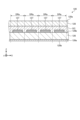
- FIG. 4 is a cross-sectional view of the pressure sensor shown in FIG.
- FIG. 5 is a diagram showing a circuit configuration of the pressure sensor shown in FIG.
- FIG. 6 is a plan view of the optical sensor shown in FIG.
- FIG. 7 is a cross-sectional view of the optical sensor shown in FIG.
- FIG. 8 is a diagram showing a circuit configuration of the optical sensor shown in FIG.
- FIG. 9 is a block diagram of the detection system.
- FIG. 10 is a diagram showing pressure distribution information when a predetermined portion is in contact with the contact area.
- FIG. 10 is a diagram showing pressure distribution information when a predetermined portion is in contact with the contact area.
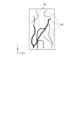
- FIG. 11A is a diagram showing a blood vessel pattern of a first biometric image.
- FIG. 11B is a diagram showing a blood vessel pattern of the second biometric image.
- FIG. 11C is a diagram showing a blood vessel pattern of the third biometric image.
- FIG. 11D is a diagram showing a blood vessel pattern of the fourth biometric information image.
- FIG. 11E is a diagram showing a blood vessel pattern of the fifth biometric image.
- FIG. 12 is a flow chart showing the process executed by the control device in the registration mode.
- FIG. 13 is a flowchart executed by the control device in the authentication mode.
- FIG. 14 is a side view of a detection device according to a modified embodiment of the present disclosure.
- FIG. 15 is a schematic diagram showing a configuration of a pressure sensor according to a modified example of the present disclosure.
- FIG. 16 is a cross-sectional view of the pressure sensor shown in FIG.
- the X and Y directions shown in the drawings correspond to directions parallel to the plate surface of the substrate included in the detection device 10.
- the +X and -X sides of the X direction and the +Y and -Y sides of the Y direction correspond to the sides of the detection device 10.
- the Z direction corresponds to the thickness direction of the detection device 10
- the +Z side of the Z direction corresponds to the front side of the detection device 10
- the -Z side of the Z direction corresponds to the rear side of the detection device 10.
- “planar view” refers to viewing the detection device 10 from the +Z side toward the -Z side along the Z direction. Note that the X, Y, and Z directions are merely examples, and the present disclosure is not limited to these directions.
- FIG. 1 is a diagram showing the configuration of a detection system 1 according to an embodiment of the present disclosure.
- the detection system 1 is a system that detects biometric information of a user and authenticates that the user is the user.
- the biometric information is a blood vessel pattern.
- the biometric information may also be a fingerprint pattern.
- the detection system 1 includes a detection device 10 and a control device 50. The detection device 10 and the control device 50 are electrically connected to each other.
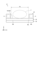
- FIG. 2 is a side view of the detection device 10.
- the detection device 10 has a contact area TR on its front surface (hereinafter referred to as contact surface 10a) that is in contact with a specific part F of the user.
- the specific part F is the user's finger.
- the specific part F contacts the contact area TR while extending along the Y direction.
- the specific part F may be the entire hand of the user or a part of the hand (e.g., the palm).
- the detection device 10 includes a pressure sensor 20, a light source device 30, and an optical sensor 40.
- the optical sensor 40 and the pressure sensor 20 are flat and rectangular in shape with the Y direction as the longitudinal direction in a plan view.
- the optical sensor 40 and the pressure sensor 20 overlap each other in the Z direction.
- FIG. 4 is a cross-sectional view of the pressure sensor 20 shown in FIG. 3.
- FIG. 5 is a diagram showing the circuit configuration of the pressure sensor 20 shown in FIG. 3.
- the array substrate 21 includes a first substrate 21a and an array layer 21b.
- the first substrate 21a is electrically insulating.
- the first substrate 21a has relatively high rigidity.
- the first substrate 21a is, for example, a glass substrate, a resin substrate, or a resin film.
- the rear surface of the first substrate 21a corresponds to the rear surface 20b of the pressure sensor 20.
- the array layer 21b is disposed on the front surface of the first substrate 21a.
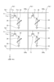
- the array layer 21b includes an insulating layer IL shown in FIG. 4, a first transistor T1 shown in FIG. 4 and FIG. 5, a first gate line GL1 and a first signal line SL1 shown in FIG. 5, and a first gate line driving circuit GC1 and a first signal line selection circuit SC1 shown in FIG. 3.
- the first gate line GL1, the first signal line SL1, the first transistor T1, the first gate line driving circuit GC1, and the first signal line selection circuit SC1 are disposed on the front surface of the first substrate 21a.
- the insulating layer IL shown in FIG. 4 has electrical insulation properties and covers the first gate line GL1, the first signal line SL1, the first transistor T1, the first gate line driving circuit GC1, and the first signal line selection circuit SC1.
- the front surface of the insulating layer IL is planar.
- the front surface of the insulating layer IL corresponds to the front surface 21c of the array substrate 21.
- the front surface 21c of the array substrate 21 corresponds to the "first surface.”
- the multiple first gate lines GL1 extend along the X direction and are arranged on the front surface of the first substrate 21a in a line-up along the Y direction.
- the multiple first gate lines GL1 are electrically connected to the first gate line driving circuit GC1.
- the multiple first signal lines SL1 extend along the Y direction and are arranged on the front surface of the first substrate 21a in a line-up along the X direction.
- the multiple first signal lines SL1 are electrically connected to the first signal line selection circuit SC1.
- the first signal line selection circuit SC1 is, for example, a multiplexer. An area surrounded by two adjacent first gate lines GL1 and two adjacent first signal lines SL1 corresponds to one individual detection area DRa.
- One array electrode 22 and one common electrode 23 are arranged in one individual detection region DRa.
- the array electrodes 22 and the common electrodes 23 are each arranged in a matrix in the detection region DR in a plan view.
- the first transistor T1 is disposed in each individual detection region DRa. As shown in FIG. 4, the first transistor T1 includes a semiconductor layer T1a, a gate insulating film T1b, a gate electrode T1c, a drain electrode T1d, and a source electrode T1e.
- the gate electrode T1c is electrically connected to the first gate line GL1.
- the drain electrode T1d is electrically connected to the array electrode 22.
- the source electrode T1e is electrically connected to the first signal line SL1.
- the array electrode 22 and the common electrode 23 are disposed on the front surface 21c of the array substrate 21.
- the array electrode 22 and the common electrode 23 are formed of a metal material such as ITO (Indium Tin Oxide).
- the array electrode 22 and the common electrode 23 may be formed of different metal materials.
- the first sensor layer 24 faces the front surface 21c of the array substrate 21 and is disposed at a distance from the array substrate 21 on the +Z side.
- the first sensor layer 24 is supported by a spacer (not shown) disposed on the array substrate 21.
- the first sensor layer 24 faces the array electrode 22 and the common electrode 23 at a distance.
- the first sensor layer 24 has the flexibility to deform when a specific portion F comes into contact with the detection region DR.
- the first sensor layer 24 contains multiple conductive microparticles and is formed from a resin material with relatively high electrical insulation. The multiple microparticles are dispersed inside the first sensor layer 24 and are separated from each other. The first sensor layer 24 is deformed when a specific part F of the user comes into contact with the detection region DR (contact region TR), and is compressed by contacting the array substrate 21.
- the spacing between the multiple microparticles becomes smaller, and the electrical resistance value of the first sensor layer 24 becomes smaller.
- the first protective layer 25 is disposed on the front surface of the first sensor layer 24.
- the first protective layer 25 has electrical insulation properties.
- the first protective layer 25 has flexibility such that it deforms together with the first sensor layer 24 when a specific portion F comes into contact with the detection region DR.
- the front surface of the first protective layer 25 corresponds to the detection surface 20a of the pressure sensor 20.
- the pressure sensor 20 is also translucent. Specifically, at least the material of the components that make up the pressure sensor 20 and that overlap the detection region DR in a plan view is translucent.
- a constant amount of current is supplied to the common electrode 23 from the control device 50 via a conductor (not shown) arranged on the array substrate 21.
- the first gate line driving circuit GC1 sequentially or simultaneously selects the multiple first gate lines GL1 based on a control signal output from the control device 50, and supplies a gate driving signal that drives the gate of the first transistor T1 to the selected first gate line GL1.
- the first signal line selection circuit SC1 selects the first signal line SL1 based on a control signal output from the control device 50, and electrically connects the selected first signal line SL1 to the control device 50.
- the current of the first gate line GL1 to which the gate driving signal is supplied and the array electrode 22 of the individual detection area DRa corresponding to the selected first signal line SL1 is supplied to the control device 50.
- the first sensor layer 24 When the user's specific part F is not in contact with the individual detection area DRa, the first sensor layer 24 is not deformed and the common electrode 23 and the array electrode 22 are not electrically connected. In this case, no current flows through the array electrode 22, and the current value of the array electrode 22 is zero.
- the first sensor layer 24 deforms and comes into contact with the array substrate 21, electrically connecting the common electrode 23 and the array electrode 22 via the first sensor layer 24. In this case, a current is supplied to the array electrode 22 from the common electrode 23 via the first sensor layer 24. Furthermore, the greater the pressure acting on the individual detection area DRa, the greater the compression amount of the first sensor layer 24, and the smaller the electrical resistance value of the first sensor layer 24. Therefore, the greater the pressure acting on the individual detection area DRa, the greater the current value of the array electrode 22.
- the current value of the array electrode 22 changes depending on the magnitude of the pressure acting on the individual detection area DRa.
- the current of the array electrode 22 is supplied to the control device 50.
- the control device 50 acquires the current value of the array electrode 22 as the magnitude of the pressure acting on the individual detection area DRa (pressure value). That is, the pressure sensor 20 detects the magnitude of the pressure acting on the individual detection area DRa and outputs it to the control device 50.
- multiple individual detection areas DRa are arranged in a matrix in the detection area DR. Therefore, the pressure sensor 20 supplies the current of the array electrode 22 for each of the multiple individual detection areas DRa to the control device 50.
- the control device 50 acquires the output of the pressure sensor 20 as pressure distribution information of the detection area DR. That is, the pressure sensor 20 detects the pressure acting on the detection area DR and outputs it to the control device 50 as pressure distribution information.
- the light source device 30 is disposed on the contact surface 10a side as shown in Figs. 1 and 2.
- the light source device 30 has a plurality of light sources 31.
- the light sources 31 are, for example, LEDs (Light Emitting Diodes).
- the plurality of light sources 31 are arranged side by side along the Y direction on both sides of the contact region TR (detection region DR) in the X direction.
- the light source 31 emits light toward a specific portion F that is in contact with the contact area TR.
- the light from the light source 31 is reflected inside the specific portion F and enters the pressure sensor 20 as reflected light.
- the pressure sensor 20 is translucent. Therefore, the reflected light passes through the pressure sensor 20 and enters the light sensor 40.
- FIG. 6 is a plan view of the optical sensor 40 shown in FIG. 2.
- the optical sensor 40 captures an image of the specific part F in contact with the contact area TR.
- the image of the specific part F captured by the optical sensor 40 includes the contact range of the specific part F in contact with the contact area TR.
- the optical sensor 40 is disposed on the opposite side (i.e., back surface 20b) of the pressure sensor 20 opposite the detection surface 20a. In other words, the specific part F of the user indirectly contacts the optical sensor 40 via the pressure sensor 20.
- the optical sensor 40 has an imaging area PR on its front surface (hereinafter referred to as the imaging surface 40a) that captures an image of a specific area F.
- the imaging area PR coincides with the detection area DR of the pressure sensor 20 in a plan view.
- the imaging region PR is divided into a number of individual imaging regions PRa.
- the individual imaging regions PRa are arranged in a matrix along the X and Y directions.
- the photosensor 40 also includes a second gate line driving circuit GC2 and a second signal line selection circuit SC2 at a position outside the imaging region PR in a plan view.
- FIG. 7 is a cross-sectional view of the optical sensor 40 shown in FIG. 6.
- FIG. 8 is a diagram showing the circuit configuration of the optical sensor 40 shown in FIG. 6.
- the optical sensor 40 includes a second substrate 41, a circuit formation layer 42, an organic insulating film 43, an inorganic insulating film 44, a second sensor layer 45, and a second protective layer 46.
- the second substrate 41 has electrical insulation properties.
- the second substrate 41 has relatively high rigidity.
- the second substrate 41 is, for example, a glass substrate, a resin substrate, or a resin film.
- the rear surface of the second substrate 41 corresponds to the rear surface 40b of the optical sensor 40.
- the circuit formation layer 42 is disposed on the front surface of the second substrate 41.
- the second gate line driving circuit GC2 and the second signal line selection circuit SC2 shown in FIG. 6, as well as the second gate line GL2, the second signal line SL2, and the second transistor T2 shown in FIG. 8 are disposed.
- the organic insulating film 43 is disposed on the front surface of the circuit formation layer 42.
- the organic insulating film 43 is formed of an organic insulating material having electrical insulation properties.
- the organic insulating film 43 covers the second gate line GL2, the second signal line SL2, the second transistor T2, the second gate line driving circuit GC2, and the second signal line selection circuit SC2.
- the inorganic insulating film 44 is disposed on the front surface of the organic insulating film 43.
- the inorganic insulating film 44 is formed from an inorganic insulating material that has electrical insulating properties.
- the second gate lines GL2 extend along the X direction and are arranged on the front surface of the second substrate 41 in a lined-up state along the Y direction.
- the second gate lines GL2 are electrically connected to the second gate line driving circuit GC2.
- the second signal lines SL2 extend along the Y direction and are arranged on the front surface of the second substrate 41 in a lined-up state along the X direction.
- the second signal lines SL2 are electrically connected to the second signal line selection circuit SC2.
- the second signal line selection circuit SC2 is, for example, a multiplexer. An area surrounded by two adjacent second gate lines GL2 and two adjacent second signal lines SL2 corresponds to one individual imaging area PRa.
- Each individual imaging region PRa includes a capacitive element Ca, a second transistor T2, and a photodiode PD.
- the photodiodes PD overlap the contact region TR (detection region DR) in a plan view, and are arranged in a matrix.
- the capacitance element Ca is a capacitance (sensor capacitance) formed in the photodiode PD, and is equivalently electrically connected in parallel with the photodiode PD.
- the gate of the second transistor T2 is electrically connected to the second gate line GL2.
- One of the source and drain of the second transistor T2 is electrically connected to the second signal line SL2.
- the other of the source and drain of the second transistor T2 is electrically connected to the anode of the photodiode PD and the capacitance element Ca.
- the second sensor layer 45 shown in FIG. 7 includes a lower electrode 45a, a lower buffer layer 45b, an active layer 45c, an upper buffer layer 45d, and an upper electrode 45e.
- the portion of the second sensor layer 45 that overlaps with the lower electrode 45a corresponds to the photodiode PD shown in FIG. 8.
- Multiple lower electrodes 45a are arranged on the front surface of the inorganic insulating film 44.
- One lower electrode 45a is arranged in one individual imaging region PRa.
- multiple lower electrodes 45a are arranged in a matrix in the imaging region PR in a plan view.
- the lower electrodes 45a correspond to the anode electrodes of the photodiodes PD.
- the lower electrodes 45a are formed of a metal material such as ITO (Indium Tin Oxide).
- the lower buffer layer 45b is disposed on the front surface of the inorganic insulating film 44 so as to cover the lower electrode 45a.
- the lower buffer layer 45b functions as a hole transport layer.
- the lower buffer layer 45b is made of, for example, tungsten oxide (WO 3 ), molybdenum oxide, or the like.
- the active layer 45c is disposed on the front surface of the lower buffer layer 45b.
- the electrical characteristics (e.g., electrical resistance value) of the active layer 45c change according to the light incident on the active layer 45c.
- An organic semiconductor is used for the active layer 45c.
- the photodiode PD is an OPD (Organic Photodiode).
- the active layer 45c is, for example, a bulk heterostructure in which a p-type organic semiconductor and an n-type fullerene derivative (PCBM), which is an n-type organic semiconductor, are mixed.
- PCBM Organic Photodiode
- the upper buffer layer 45d is disposed on the front surface of the active layer 45c.
- the upper buffer layer 45d functions as an electron transport layer.
- the upper buffer layer 45d is formed of, for example, ethoxylated polyethyleneimine (PEIE).
- the upper electrode 45e is disposed on the front surface of the upper buffer layer 45d.
- the upper electrode 45e is the cathode electrode of the photodiode PD.
- the upper electrode 45e is disposed continuously across the entire imaging region PR in a plan view.
- the upper electrode 45e faces multiple lower electrodes 45a, sandwiching the upper buffer layer 45d, the active layer 45c, and the lower buffer layer 45b between them.
- the upper electrode 45e is formed of a metal material such as ITO (Indium Tin Oxide).
- the configuration of the photodiode PD shown in Figures 7 and 8 is merely an example, and it goes without saying that the configuration is not limited to the above.
- the upper electrode 45e may correspond to the anode electrode
- the lower electrode 45a may correspond to the cathode electrode.
- the second protective layer 46 is disposed on the front surface of the second sensor layer 45.
- the second protective layer 46 has electrical insulation properties.
- the front surface of the second protective layer 46 corresponds to the imaging surface 40a of the optical sensor 40.
- a predetermined voltage is applied to the anode (lower electrode 45a) of the photodiode PD from the control device 50 via a conductor (not shown) arranged in the circuit formation layer 42.
- the second gate line driving circuit GC2 sequentially or simultaneously selects the second gate lines GL2 based on a control signal output from the control device 50, and supplies a gate driving signal that drives the gate of the second transistor T2 to the selected second gate line GL2.
- the second signal line selection circuit SC2 selects the second signal line SL2 based on a control signal output from the control device 50, and electrically connects the selected second signal line SL2 to the control device 50.
- reflected light When a specific part F of the user is in contact with the contact area TR, light from the light source 31 reflected by the specific part F (reflected light) is incident on the individual imaging area PRa.
- the amount of reflected light varies depending on the shape and internal structure of the specific part F (e.g., the position of blood vessels).
- the capacitance of the capacitive element Ca varies depending on the amount of reflected light.
- a current corresponding to the capacitance of the capacitive element Ca is supplied to the control device 50. Furthermore, as described above, a plurality of individual imaging areas PRa are arranged in a matrix in the imaging area PR. That is, the optical sensor 40 supplies a current corresponding to the capacitance of the capacitive element Ca for each of the plurality of individual imaging areas PRa to the control device 50.
- the control device 50 acquires a current corresponding to the capacitance of the plurality of capacitive elements Ca as an image of the specific part F in contact with the contact area TR. That is, when the specific part F of the user is in contact with the contact area TR, the optical sensor 40 outputs an image of the specific part F to the control device 50.
- the timing at which the pressure sensor 20 outputs the pressure distribution information and the timing at which the optical sensor 40 outputs the image of the specified area F are synchronized. Specifically, the interval at which the pressure sensor 20 outputs the pressure distribution information are equal to the interval at which the optical sensor 40 outputs the image of the specified area F. Furthermore, the timing at which the pressure sensor 20 outputs the pressure distribution information and the timing at which the optical sensor 40 outputs the image of the specified area F may be simultaneous. This allows the control device 50 to associate the pressure distribution information output by the pressure sensor 20 with the image of the specified area F output by the optical sensor 40. Furthermore, the pressure sensor 20 may continuously output the pressure distribution information, and the optical sensor 40 may continuously output the image of the specified area F.
- the optical sensor 40 captures an image of the specific part F including the contact range of the specific part F that contacts the contact area TR. Therefore, compared to a case in which the detection device 10 is equipped with a camera that captures an image of the specific part F and the camera captures an image of the specific part F while the camera and the specific part F are separated from each other, the detection device 10 does not need to be equipped with a support base that supports the specific part F. Therefore, the detection device 10 can be made smaller.
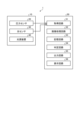
- FIG. 9 is a block diagram of the detection system 1.
- the control device 50 is a computer, and includes, for example, a CPU (Central Processing Unit), a ROM (Read Only Memory), a RAM (Random Access Memory), a memory circuit 53 (described below), an input interface, and an output interface.
- the CPU, ROM, RAM, and memory circuit 53 are connected by an internal bus. Programs such as the BIOS are stored in the ROM.
- the memory circuit 53 is, for example, a HDD (Hard Disk Drive) or flash memory, and stores an operating system program and application programs.
- the CPU realizes various functions by executing programs stored in the ROM or memory circuit 53 while using the RAM as a work area.
- the control device 50 includes an acquisition circuit 51, an image processing circuit 52, a memory circuit 53, a judgment circuit 54, an output circuit 55, and a display circuit 56.
- the acquisition circuit 51 acquires the pressure distribution information output by the pressure sensor 20 and the image of the specified area F output by the optical sensor 40.
- FIG. 10 is a diagram showing pressure distribution information PDI when a specific portion F is in contact with contact area TR.
- the pressure distribution information PDI is divided into four pressure ranges.
- the magnitude of pressure in the pressure distribution information PDI increases in the order of the first pressure range H1, the second pressure range H2, the third pressure range H3, and the fourth pressure range H4.
- the first pressure range H1 has a pressure value of zero.
- the pressure distribution information PDI shown in FIG. 10 is an example, and it goes without saying that the number and shape of the pressure ranges are not limited to the pressure distribution information PDI shown in FIG. 10.
- the acquisition circuit 51 shown in FIG. 9 also acquires an image of the specified area F captured by the optical sensor 40 in a state synchronized with the pressure distribution information output by the pressure sensor 20.
- the image processing circuit 52 generates a biometric image including the user's biometric information based on the image of the specific area F captured by the optical sensor 40.
- the biometric information is a blood vessel pattern (vein pattern).
- the image processing circuit 52 acquires the image of the specific area F captured by the optical sensor 40 from the acquisition circuit 51.
- the image processing circuit 52 adjusts the brightness and contrast of the image of the specific area F to extract the blood vessel pattern (vein pattern) of the specific area F and generate a biometric information image.
- FIG. 11A is a diagram showing the vascular pattern of a first biometric image G1.
- FIG. 11B is a diagram showing the vascular pattern of a second biometric image G2.
- FIG. 11C is a diagram showing the vascular pattern of a third biometric image G3.
- FIG. 11D is a diagram showing the vascular pattern of a fourth biometric image G4.
- FIG. 11E is a diagram showing the vascular pattern of a fifth biometric image G5.
- the first biometric image G1, the second biometric image G2, the third biometric image G3, the fourth biometric image G4, and the fifth biometric image G5 have the largest maximum pressure values in the pressure distribution information output by the pressure sensor 20 synchronized with the image of the original specified part F, in that order.
- the first biometric image G1 has the smallest maximum pressure value
- the fifth biometric image G5 has the largest maximum pressure value.
- the pressing force with which the specified part F is pressed against the contact region TR when the image of the original specified part F is captured is largest in the order of the first biometric image G1, the second biometric image G2, the third biometric image G3, the fourth biometric image G4, and the fifth biometric image G5.
- the blood vessel pattern disappears or becomes blurred on both sides in the X direction compared to the third biometric information image G3 shown in FIG. 11C.
- the blood vessel pattern disappears compared to the third biometric information image G3 shown in FIG. 11C.
- the blood vessel pattern disappears or becomes blurred on both sides in the X direction compared to the third biometric information image G3 shown in FIG. 11C.
- the blood vessel pattern has disappeared compared to the third biometric information image G3 shown in FIG. 11C.
- the X direction length of area A2 is shorter than the X direction length of area A1 in FIG. 11A.
- the vascular pattern has disappeared in the area A3 shown in Fig. 11D, compared to the third biometric image G3 shown in Fig. 11C. This occurs because the pressing force corresponding to the fourth biometric image G4 shown in Fig. 11D is greater than the pressing force corresponding to the third biometric image G3 shown in Fig. 11C, causing the blood flow condition at the specified site F to deteriorate.
- the vascular pattern has disappeared in the area A4 shown in Fig. 11E, compared to the third biometric image G3 shown in Fig. 11D. This occurs because the pressing force corresponding to the fifth biometric image G5 shown in Fig. 11E is greater than the pressing force corresponding to the fourth biometric image G4 shown in Fig. 11D, causing the blood flow condition at the specified site F to deteriorate.
- the vascular pattern changes according to the pressure corresponding to the biometric information image.
- the greater the pressure corresponding to the biometric information image the greater the pressure output by the pressure sensor 20.
- the vascular pattern changes according to the pressure output by the pressure sensor 20.
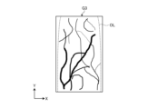
- the image processing circuit 52 may extract the contour of the specified part F in the bioinformation image. Specifically, the image processing circuit 52 first extracts the contour of the specified part F in the pressure distribution information synchronized with the original image of the specified part F in the bioinformation image. For example, the boundary RL between the first pressure range H1 and the second pressure range H2, where the pressure value is zero in the pressure distribution information PDI shown in FIG. 10, is extracted as the contour of the specified part F. Furthermore, the image processing circuit 52 extracts a line (for example, the dashed line OL shown in FIG.
- the image processing circuit 52 can clearly distinguish between the contour of the specific area F and the vascular pattern in the biometric information image. Furthermore, the vascular pattern is located inside the contour of the specific area F. Therefore, the image processing circuit 52 can appropriately extract the vascular pattern.
- the memory circuitry 53 stores the biometric information image and the pressure distribution information output by the pressure sensor 20 in association with each other (details will be described later).
- the determination circuit 54 uses the biometric information image to determine whether or not the user is the actual user (details will be described later). If the determination circuit 54 determines that the user is the actual user, it authenticates that the user is the actual user.
- the output circuit 55 outputs the judgment result of the judgment circuit 54.
- the output circuit 55 outputs the judgment result to the display circuit 56.
- the display circuit 56 displays the judgment result.
- the display circuit 56 is, for example, a display.
- the control device 50 also operates in either a registration mode or an authentication mode.
- the registration mode is a mode in which the user registers the detection system 1 so that the user can use the detection system 1.
- the authentication mode is a mode in which the detection system 1 authenticates that the user is the authentic user.
- Switching between registration mode and authentication mode is performed, for example, by the user inputting a selection instruction into an input device (e.g., a keyboard and a touch panel: not shown) provided in the control device 50.
- an input device e.g., a keyboard and a touch panel: not shown
- FIG. 12 is a flowchart executed by the control device 50 in the registration mode.
- the control device 50 executes the flowchart shown in FIG. 12 in response to the selection of the registration mode.
- step S1 the control device 50 (display circuit 56) displays that the specific part F is to be brought into contact with the contact area TR. At this time, the control device 50 also displays on the display circuit 56 that the pressure of the specific part F against the contact area TR is to be changed.
- the user brings the specific part F into contact with the contact area TR in accordance with the display of the display circuit 56, and changes the pressure.
- the optical sensor 40 captures multiple images of the specific part F and outputs them to the control device 50.
- the pressure sensor 20 detects multiple pressures acting on the detection area DR and outputs them to the control device 50.
- the images of the specific part F output from the optical sensor 40 and the pressures output from the pressure sensor 20 are synchronized.
- step S2 the control device 50 (acquisition circuit 51) acquires multiple images of the specific area F output by the optical sensor 40 and multiple pieces of pressure distribution information output by the pressure sensor 20.
- the control device 50 acquires multiple images of the specific area F output by the optical sensor 40 and multiple pieces of pressure distribution information output by the pressure sensor 20.
- the control device 50 selects multiple pieces of pressure distribution information from the multiple pieces of pressure distribution information acquired.
- the control device 50 image processing circuit 52 calculates the area occupied by a predetermined pressure range in the detection region DR for each of the multiple pieces of pressure distribution information acquired in step S2.
- the predetermined pressure range is a range of pressure values in which the blood flow state of the predetermined part F in contact with the contact region TR is appropriate and the image processing circuit 52 can appropriately extract a blood vessel pattern from the image of the predetermined part F.
- the control device 50 selects a predetermined number (an integer equal to or greater than 2: for example, 5) of pressure distribution information whose calculated areas are within a predetermined area range from the multiple pressure distribution information acquired in step S2.
- the predetermined area range is an area range in which the judgment circuit 54 can appropriately perform the judgment described below. Note that if the number of pieces of pressure distribution information whose calculated areas are within the predetermined area range exceeds the predetermined number, the control device 50 may select pressure distribution information in descending order of calculated area. Furthermore, if the number of pieces of pressure distribution information whose calculated areas are within the predetermined area range is one, or if the number of pieces of pressure distribution information selected does not reach the predetermined number, the control device 50 may return the program to step S1.
- step S4 the control device 50 selects images of the specified area F that are synchronized with the selected pressure distribution information from among the multiple images of the specified area F acquired in step S2.
- the number of selected images of the specified area F is equal to the number of selected pressure distribution information (predetermined number).
- step S6 the control device 50 (memory circuitry 53) stores the biometric image and pressure distribution information. Specifically, the control device 50 associates the biometric image generated in step S5 with the pressure distribution information corresponding to the biometric image (the pressure distribution information selected in step S3), and stores multiple copies of each.
- the control device 50 also stores the multiple biometric images and multiple pieces of pressure distribution information in association with identification information (e.g., an identification number) that identifies the user. This allows the control device 50 to identify that the user corresponding to the multiple biometric images and multiple pieces of pressure distribution information stored in the memory circuitry 53 is the user corresponding to the identification information.
- the control device 50 acquisition circuitry 51 acquires the identification information when the user inputs the identification information into the input device. When the control device 50 completes step S6, it terminates the program.
- the biometric information images and pressure distribution information stored in the memory circuit 53 are referred to as registered images and registered pressure information.
- the registered images and registered pressure information correspond to each other.
- the registered pressure information is pressure distribution information detected by the pressure sensor 20 when the image of the original specified part F of the registered image is captured by the optical sensor 40.
- the memory circuit 53 stores multiple registered images, multiple registered pressure information, and identification information corresponding to at least one user in a state in which they correspond to each other.
- FIG. 13 is a flowchart executed by the control device 50 in the authentication mode.
- the control device 50 executes the flowchart shown in FIG. 13 in response to the selection of the authentication mode.
- the control device 50 performs one-to-one authentication using a registered image and registered pressure information corresponding to the user.
- selecting the authentication mode the user inputs the above-mentioned identification information into the input device.
- step S11 the control device 50 (display circuit 56) displays a message indicating that the specified part F should be brought into contact with the contact area TR. The user brings the specified part F into contact with the contact area TR in accordance with the display of the display circuit 56.
- step S12 the control device 50 (acquisition circuit 51) acquires the image of the specified area F output by the optical sensor 40 and the pressure distribution information output by the pressure sensor 20.
- the control device 50 acquires the image of the specified area F and the pressure distribution information one by one.
- the acquired image of the specified area F and the pressure distribution information are synchronized with each other as described above and correspond to each other.
- step S13 the control device 50 determines whether the area occupied by the predetermined pressure range in the detection region DR for the acquired pressure distribution information is within a predetermined area range. Specifically, the control device 50 (image processing circuit 52) calculates the area occupied by the predetermined pressure range in the detection region DR for the pressure distribution information acquired in step S12, similar to step S3 above.
- step S13 If the calculated area is outside the predetermined area range (No in step S13), the control device 50 returns the program to step S11. As a result, if the calculated area is outside the predetermined area range, the control device 50 acquires again in step S12 the image of the predetermined part F output by the optical sensor 40 and the pressure distribution information output by the pressure sensor 20. In other words, if the area occupied by the predetermined pressure range in the detection region DR for the pressure distribution information acquired in step S12 is outside the predetermined area range, no judgment is made by the judgment circuit 54 described below.
- step S13 the control device 50 advances the program to step S14.
- the control device 50 acquires pressure distribution information in which the calculated area is within the predetermined area range, and an image of the specified part F corresponding to the pressure distribution information. If the calculated area is within the predetermined area range, the control device 50 can acquire an image of the specified part F in which the blood flow state of the specified part F is appropriate and the vascular pattern can be appropriately recognized in the bioinformation image. Therefore, the judgment circuit 54 can appropriately perform the judgment described below.
- step S15 the control device 50 selects one piece of registered pressure information from the multiple pieces of registered pressure information based on the acquired pressure information. Specifically, the control device 50 selects one piece of registered pressure information that is closest to the acquired pressure information from the multiple pieces of registered pressure information that correspond to the input identification information. For example, the control device 50 calculates the range in which the pressure values of the registered pressure information and the acquired pressure information overlap for each of the multiple pieces of registered pressure information, and selects the registered pressure information with the largest area of that range in the detection region DR from the multiple pieces of registered pressure information.
- step S16 the control device 50 selects one registered image (e.g., the biometric information image shown in FIG. 11C) that corresponds to one registered pressure information.
- one registered image e.g., the biometric information image shown in FIG. 11C
- the control device 50 determines whether the acquired image matches one registered image.
- the control device 50 compares the acquired image with one registered image and determines whether they match using a known method. For example, the control device 50 extracts multiple feature points of the vascular pattern of the acquired image and one registered image, and determines that the acquired image matches one registered image if the rate at which the feature points match is equal to or greater than a first predetermined rate.
- the first predetermined rate is the rate at which the vascular pattern of the acquired image and the vascular pattern of one registered image can be recognized as matching. If the acquired image matches one registered image, the control device 50 authenticates that the user is the authorized user.
- step S17 If the control device 50 determines that the acquired image matches one of the registered images (Yes in step S17), the program proceeds to step S18.
- step S18 the control device 50 (display circuit 56) displays that the user has been authenticated as the user.
- step S18 ends, the control device 50 ends the program.
- step S17 if the rate at which both feature points match is less than the first predetermined rate (No in step S17), the control device 50 determines that the acquired image does not match one registered image, and returns the program to step S11. Note that the control device 50 may end the program if the number of times it determines No in step S16 is equal to or greater than a predetermined number (e.g., five times).
- a predetermined number e.g., five times.
- the control device 50 selects one registered image from the multiple registered images taking into consideration the acquired pressure information and the registered pressure information, compares the acquired image with the one registered image, and authenticates that the user is the real person. If the control device 50 does not take into consideration the acquired pressure information and the registered pressure information, the pressure of the specific part F acting on the contact area TR may vary, which may cause the shape of the vascular pattern in the registered image to differ relatively greatly from the shape of the vascular pattern in the acquired image. For example, if one registered image corresponds to the biometric information image shown in FIG. 11A and the acquired image corresponds to the biometric information image shown in FIG. 11C, the rate at which the two feature points match will be smaller than a first predetermined rate. In this case, the user will not be authenticated as the real person, even though he or she is the real person.
- control device 50 can properly authenticate the user by selecting one registered image from multiple registered images while taking into account the acquired pressure information and registered pressure information as described above.
- the image processing circuit 52 in the registration mode and authentication mode, the image processing circuit 52 generates a biometric image including the user's biometric information based on the image of the specific part F captured by the optical sensor 40.
- the memory circuit 53 stores the biometric image generated by the image processing circuit 52 and the pressure detected by the pressure sensor 20 when the image of the specific part F corresponding to the biometric image is captured as a registered image and registered pressure information corresponding to the registered image.
- the determination circuit 54 acquires the biometric image generated by the image processing circuit 52 and the pressure detected by the pressure sensor 20 when the image of the specific part F corresponding to the biometric image is captured as an acquired image and acquired pressure information corresponding to the acquired image, and determines whether the acquired image and the registered image match in consideration of the acquired pressure information and the registered pressure information.
- the detection system 1 does not need to include the light source device 30.
- external light is reflected at the predetermined location F and enters the optical sensor 40 as reflected light.
- the control device 50 may also be able to register biometric images and pressure distribution information for multiple people (N people). In this case, when authenticating a user in authentication mode, the control device 50 may perform 1:N authentication using the registered images and registered pressure information of multiple people (N people) stored in the memory circuit 53. In other words, if the user is included in any of the multiple people (N people) registered, the user is identified as the user corresponding to the identification information.
- the control device 50 may also issue a warning if the calculated area is outside the specified area range in step S13 shown in FIG. 12 (No in step S13). Specifically, the control device 50 (display circuit 56) warns the user by displaying that the pressure of the specified area F against the contact area is not appropriate.
- the control device 50 may also be further provided with a speaker and may warn the user by outputting sound from the speaker.
- control device 50 may select pressure distribution information in which the proportion of the pressure value range of the pressure distribution information that is occupied by a predetermined pressure range is equal to or greater than a second predetermined proportion.
- the second predetermined proportion is a range of pressure values that corresponds to an area in the detection region DR where the determination circuit 54 can appropriately perform the above determination.
- control device 50 may select, from the multiple pieces of acquired pressure distribution information, pressure distribution information whose maximum pressure value (or median pressure value) is within a predetermined pressure range.
- the control device 50 may also select one piece of pressure distribution information from the multiple pieces of pressure distribution information acquired in step S3 of FIG. 12. For example, the control device 50 may select the pressure distribution information in which the area occupied by the specified pressure range in the detection region DR is the largest. In this case, the piece of pressure distribution information selected in step S13 corresponds to the piece of registered pressure information shown in step S15 of FIG. 13.
- the control device 50 may determine whether the proportion of the predetermined pressure range in the range of pressure values in the acquired pressure distribution information (acquired pressure information) is equal to or greater than the second predetermined proportion. If the proportion of the predetermined pressure range in the range of pressure values in the acquired pressure information is equal to or greater than the second predetermined proportion (Yes in step S13), the control device 50 advances the program to step S14. On the other hand, if the proportion of the predetermined pressure range in the range of pressure values in the acquired pressure information is smaller than the second predetermined proportion (No in step S13), the control device 50 returns the program to step S11.
- control device 50 may calculate the overlapping range of the pressure values of the registered pressure information and the acquired pressure distribution information (acquired pressure information) for each of the multiple registered pressure information, and select the one registered pressure information with the largest range.
- the control device 50 may compare the maximum pressure value of the multiple registered pressure information with the maximum pressure value of the acquired pressure information, and select the registered pressure information having the maximum pressure value closest to the maximum pressure value of the acquired pressure information.
- the control device 50 may also compare the median pressure value of the multiple registered pressure information with the median pressure value of the acquired pressure information, and select the registered pressure information having the median pressure value closest to the median pressure value of the acquired pressure information.
- control device 50 may correct the acquired image in step S17 of FIG. 13 and determine whether the corrected acquired image matches one registered image. Specifically, the control device 50 first extracts the contour of the specific part F in one registered image selected in step S16 as described above based on the registered pressure information corresponding to the one registered image. Next, the control device 50 extracts the contour of the specific part F in the acquired image as described above based on the acquired pressure information. Furthermore, the control device 50 corrects the position and orientation of the specific part F in the acquired image so that the position of the contour of the specific part F in the acquired image matches the contour of the specific part F in one registered image.
- the control device 50 may generate pressure distribution information having an intermediate pressure distribution between two pieces of pressure distribution information selected in step S3 of FIG. 12 based on two pieces of pressure distribution information.
- the control device 50 (image processing circuit 52) generates a biometric information image having intermediate biometric information between the two biometric information images based on two biometric information images corresponding to the two pieces of pressure distribution information. For example, when the control device 50 acquires the first biometric information image G1 shown in FIG. 11A and the third biometric information image G3 shown in FIG. 11C, but does not acquire the second biometric information image G2 shown in FIG. 11B, the control device 50 generates the second biometric information image G2 shown in FIG. 11B based on the first biometric information image G1 and the third biometric information image G3.
- the control device 50 (storage circuit 53) stores the intermediate biometric information image and the intermediate pressure distribution information in correspondence with each other.
- the pressure sensor 20 may also have the flexibility to deform when a specific portion F comes into contact with the contact area TR.
- the array substrate 21, array electrode 22, and common electrode 23 have the flexibility to deform when a specific portion F comes into contact with the contact area TR, and the pressure sensor 20 has this flexibility as a whole.
- the optical sensor 40 may have relatively high rigidity as a whole by, for example, the second substrate 41 having a relatively high rigidity, or the optical sensor 40 may have the flexibility as a whole by having all of the members constituting the optical sensor 40 have the flexibility to deform when a specific portion F comes into contact with the contact area TR.
- the pressure sensor 20 is disposed on the opposite side (i.e., the back surface 40b) of the optical sensor 40 opposite the imaging surface 40a.
- the imaging surface 40a of the optical sensor 40 corresponds to the contact surface 10a of the detection device 10
- the imaging region PR of the optical sensor 40 coincides with the contact region TR of the detection device 10.
- the optical sensor 40 may have a relatively high rigidity as a whole, for example, by having the second substrate 41 have a relatively high rigidity, or the entire member constituting the optical sensor 40 may have the flexibility to deform when a specific portion F comes into contact with the contact region TR, thereby having the flexibility as a whole.
- the light source device 30 is disposed on the imaging surface 40a of the optical sensor 40.
- the pressure sensor 20 does not need to be translucent.
- the pressure sensor 20 may have a relatively high rigidity as a whole, for example, by having the first substrate 21a have a relatively high rigidity, or the pressure sensor 20 may have a flexibility as a whole, by having all of the members constituting the pressure sensor 20 have the flexibility to deform when the specific portion F comes into contact with the contact area TR. In this way, one of the optical sensor 40 and the pressure sensor 20 may have the flexibility to deform when the specific portion F comes into contact with the contact area TR.
- FIG. 15 is a schematic diagram showing the configuration of a pressure sensor 120 according to a modified example of the present disclosure.
- FIG. 16 is a cross-sectional view of the pressure sensor 120 shown in FIG. 15.
- the pressure sensor 120 according to this modified example is a capacitance type pressure sensor.
- the pressure sensor 120 detects the presence or absence of pressure for each individual detection area DRa.
- the pressure sensor 120 includes a third substrate 126 (corresponding to "substrate”), a plurality of electrodes 127, and a third protective layer 128.
- the third substrate 126 is configured in the same manner as the first substrate 21a of the pressure sensor 20 of the above embodiment.
- a shield 126a is disposed on the rear surface of the third substrate 126.
- the shield 126a suppresses the effect on the capacitance of the electrode 127 from the rear surface side of the pressure sensor 120.
- the rear surface of the shield 126a corresponds to the rear surface 120b of the pressure sensor 120.
- the multiple electrodes 127 are arranged on the front surface 126b (corresponding to the "second surface") of the third substrate 126.
- One electrode 127 is arranged in one individual detection area DRa.
- the multiple electrodes 127 are arranged in a matrix in the detection area DR in a plan view.
- the multiple electrodes 127 are formed from a conductive material such as ITO.
- the third protective layer 128 is disposed on the front surface 126b side of the third substrate 126, sandwiching the adhesive layer OC.
- the third protective layer 128 is formed in the same manner as the first protective layer 25 of the pressure sensor 20 of the above embodiment.
- the front surface of the third protective layer 128 corresponds to the detection surface 120a having the detection region DR.
- the control device 50 can calculate and obtain the magnitude of the pressure acting on the detection area DR (i.e., pressure value: equivalent to the pressing force of the specific part F per unit area in the detection area DR) based on the number of individual detection areas DRa with which the specific part F comes into contact.
- the pressure sensor 120 detects the pressure acting on the detection area DR and outputs it to the control device 50 as pressure value information.
- step S3 of FIG. 12 the control device 50 selects, from the multiple pieces of acquired pressure value information, multiple pieces of pressure value information whose pressure values are within a predetermined pressure range. Furthermore, in step S6 of FIG. 12, the control device 50 stores the pressure value information selected in step S3 as registered pressure information.
- control device 50 selects one piece of registered pressure information from the multiple pieces of registered pressure information in step S15 of FIG. 13, it selects the registered pressure information having a pressure value closest to the pressure value indicated by the acquired pressure information.
- Detection system 10 Detection device 10a Contact surface 20 Pressure sensor 20a Detection surface 21 Array substrate 21c Front surface (first surface) 22 Array electrode 23 Common electrode 24 First sensor layer (sensor layer) 30 Light source device 40 Optical sensor 40a Imaging surface 50 Control device 52 Image processing circuit 53 Memory circuit 54 Determination circuit 120 Pressure sensor 126 Third substrate (substrate) 126b Front (second side) 127 Electrode DR Detection area F Predetermined area G1 First biometric information image G2 Second biometric information image G3 Third biometric information image G4 Fourth biometric information image G5 Fifth biometric information image PDI Pressure distribution information PR Imaging area TR Contact area
Landscapes
- Engineering & Computer Science (AREA)
- Physics & Mathematics (AREA)
- General Physics & Mathematics (AREA)
- Health & Medical Sciences (AREA)
- Theoretical Computer Science (AREA)
- Multimedia (AREA)
- Human Computer Interaction (AREA)
- Life Sciences & Earth Sciences (AREA)
- General Health & Medical Sciences (AREA)
- Vascular Medicine (AREA)
- Heart & Thoracic Surgery (AREA)
- Biophysics (AREA)
- Pathology (AREA)
- Biomedical Technology (AREA)
- Computer Vision & Pattern Recognition (AREA)
- Medical Informatics (AREA)
- Molecular Biology (AREA)
- Surgery (AREA)
- Animal Behavior & Ethology (AREA)
- Public Health (AREA)
- Veterinary Medicine (AREA)
- Image Input (AREA)
Abstract
検出システム1は、使用者の所定部位Fが接触する接触領域TRを有する検出装置10と、使用者を認証する認証モードで動作する制御装置50と、を備える。検出装置10は、接触領域TRに接触する所定部位Fの画像を撮像する光センサ40と、所定部位Fが接触領域TRに接触したことによって生じる圧力を検出する圧力センサ20と、を備える。制御装置50は、認証モードで光センサ40によって撮像された所定部位Fの画像に基づいて生体情報画像を生成し、予め格納されている生体情報画像である登録画像と、認証モードで生成された生体情報画像である取得画像とが一致するか否かを、登録画像に対応する圧力および取得画像に対応する圧力を考慮して判定する。
Description
本開示は、検出システムおよび検出装置に関する。
特許文献1には、検出システムの一例として、例えば利用者の指の血管パターンを撮像し、登録済みの血管パターンと照合することにより利用者を認証する静脈認証システムが開示されている。
特許文献1の検出システムにおいては、CMOS(Complementary Metal Oxide Semiconductor)カメラによって構成される撮像素子を用いて指などが撮像される。この場合、撮像素子の特性により撮像素子と指とは、離れていることが必要である。よって、システムの小型化が困難である。
本開示は、使用者を認証する検出システムにおいて、小型化を図ることを目的とする。
本開示の検出システムは、使用者の所定部位が接触する接触領域を有する検出装置と、前記使用者を認証する認証モードで動作する制御装置と、を備え、前記検出装置は、前記接触領域に接触する前記所定部位の接触範囲を含む前記所定部位の画像を撮像する光センサと、前記所定部位が前記接触領域に接触したことによって生じる圧力を検出する圧力センサと、を備え、前記制御装置は、前記光センサによって撮像された前記所定部位の画像に基づいて前記使用者の生体情報を含む生体情報画像を生成する画像処理回路と、前記生体情報画像、および、前記生体情報画像に対応する前記所定部位の画像が撮像されたときに前記圧力センサによって検出された圧力を、登録画像および前記登録画像に対応する登録圧力情報として格納する記憶回路と、前記認証モードで、前記画像処理回路によって生成される前記生体情報画像、および、前記生体情報画像に対応する前記所定部位の画像が撮像されたときに前記圧力センサによって検出された圧力を、取得画像および前記取得画像に対応する取得圧力情報として取得し、前記取得圧力情報および前記登録圧力情報を考慮して前記取得画像と前記登録画像とが一致するか否かの判定をする判定回路と、を備える。
また、本開示の検出装置は、使用者の所定部位が直接または間接に接触する光センサおよび圧力センサを備え、前記光センサは、前記所定部位の画像を撮像する撮像領域を有し、前記圧力センサは、前記所定部位が接触することによって生じる圧力を検出する検出領域を有し、前記撮像領域と前記検出領域とは、平面視で重なり、前記光センサが前記画像を出力するタイミングと、前記圧力センサが前記圧力を出力するタイミングとは、同期付けされている。
以下に、本開示の各実施の形態について、図面を参照しつつ説明する。以下の実施形態に記載した内容により本開示が限定されるものではない。また、以下に記載した構成要素には、当業者が容易に想定できるもの、実質的に同一のものが含まれる。さらに、以下に記載した構成要素は適宜組み合わせることが可能である。
なお、開示はあくまで一例にすぎず、当業者において、本開示の主旨を保っての適宜変更について容易に想到し得るものについては、当然に本開示の範囲に含有されるものである。また、図面は説明をより明確にするため、実際の態様に比べ、各部の幅、厚さ、形状等について模式的に表される場合があるが、あくまで一例であって、本開示の解釈を限定するものではない。また、本明細書と各図において、既出の図に関して前述したものと同様の要素には、同一の符号を付して、詳細な説明を適宜省略することがある。
図面で示すX方向およびY方向は、検出装置10に含まれる基板の板面に平行な方向に相当する。X方向の+X側、-X側、Y方向の+Y側、-Y側は、検出装置10の側方に相当する。Z方向は、検出装置10の厚み方向に相当し、Z方向の+Z側は、検出装置10の前面側に相当し、Z方向の-Z側は、検出装置10の背面側に相当する。また、本明細書において、「平面視」は、Z方向に沿って+Z側から-Z側に向かって検出装置10を見ることである。なお、X、Y、Zの方向は一例であって、本開示はこれらの方向に限定されない。
図1は、本開示の実施形態に係る検出システム1の構成を示す図である。検出システム1は、使用者の生体情報を検出し、使用者が本人であることを認証するシステムである。生体情報は、血管パターンである。なお、生体情報は、指紋パターンでもよい。検出システム1は、検出装置10、および、制御装置50を備える。検出装置10および制御装置50は、互いに電気的に接続されている。
図2は、検出装置10の側面図である。図1および図2に示すように、検出装置10は、使用者の所定部位Fが接触する接触領域TRを前面(以下、接触面10aと称する)に有する。所定部位Fは、使用者の指である。所定部位Fは、Y方向に沿って延びる状態で接触領域TRに接触する。なお、所定部位Fは、使用者の手の全体または手の一部(例えば手のひら)でもよい。
検出装置10は、圧力センサ20、光源装置30、および、光センサ40、を備える。光センサ40および圧力センサ20は、平板形状であり、平面視でY方向を長手方向とする長方形状である。光センサ40および圧力センサ20は、Z方向で互いに重なる。
図3は、図2に示す圧力センサ20の平面図である。圧力センサ20は、所定部位Fが接触領域TRに接触したことによって生じる圧力を検出する。圧力センサ20は、圧力を検出する検出領域DRを前面(以下、検出面20aと称する)に有する。圧力センサ20の検出面20aは、検出装置10の接触面10aに相当する。検出領域DRは、接触領域TRと一致する。圧力センサ20の検出領域DRには、使用者の所定部位Fが直接接触する。
検出領域DRは、複数の個別検出領域DRaに区分けされている。複数の個別検出領域DRaは、X方向およびY方向に沿って行列状に並ぶ。また、圧力センサ20は、平面視において検出領域DRから外れた位置に第1ゲート線駆動回路GC1、および、第1信号線選択回路SC1を備える。
図4は、図3に示す圧力センサ20の断面図である。図5は、図3に示す圧力センサ20の回路構成を示す図である。
図4に示すように、圧力センサ20は、アレイ基板21、アレイ電極22、共通電極23、第1センサ層24、および、第1保護層25を備える。第1センサ層24は、「センサ層」に相当する。
アレイ基板21は、第1基板21a、および、アレイ層21bを備える。第1基板21aは、電気絶縁性を有する。第1基板21aは、比較的高い剛性を有する。第1基板21aは、例えば、ガラス基板、樹脂基板、又は樹脂フィルムである。第1基板21aの背面は、圧力センサ20の背面20bに相当する。
アレイ層21bは、第1基板21aの前面に配置される。アレイ層21bは、図4に示す絶縁層IL、図4および図5に示す第1トランジスタT1、図5に示す第1ゲート線GL1、および、第1信号線SL1、ならびに、図3に示す第1ゲート線駆動回路GC1、および、第1信号線選択回路SC1を備える。第1ゲート線GL1、第1信号線SL1、第1トランジスタT1、第1ゲート線駆動回路GC1、および、第1信号線選択回路SC1は、第1基板21aの前面に配置される。
図4に示す絶縁層ILは、電気絶縁性を有し、第1ゲート線GL1、第1信号線SL1、第1トランジスタT1、第1ゲート線駆動回路GC1、および、第1信号線選択回路SC1を被覆する。絶縁層ILの前面は、平面状である。絶縁層ILの前面は、アレイ基板21の前面21cに相当する。アレイ基板21の前面21cは、「第1面」に相当する。
図5に示すように、複数の第1ゲート線GL1は、X方向に沿って延び、Y方向に沿って並ぶ状態で第1基板21aの前面に配置される。複数の第1ゲート線GL1は、第1ゲート線駆動回路GC1に電気的に接続される。複数の第1信号線SL1は、Y方向に沿って延び、X方向に沿って並ぶ状態で第1基板21aの前面に配置される。複数の第1信号線SL1は、第1信号線選択回路SC1に電気的に接続される。第1信号線選択回路SC1は、例えばマルチプレクサである。互いに隣り合う2つの第1ゲート線GL1および互いに隣り合う2つの第1信号線SL1に囲まれている領域が1つの個別検出領域DRaに相当する。
1つの個別検出領域DRaには、1つのアレイ電極22および1つの共通電極23が配置される。つまり、アレイ電極22および共通電極23は、それぞれ、平面視において検出領域DRに行列状に複数並ぶ。
第1トランジスタT1は、1つの個別検出領域DRaに1つ配置されている。第1トランジスタT1は、図4に示すように、半導体層T1a、ゲート絶縁膜T1b、ゲート電極T1c、ドレイン電極T1d、および、ソース電極T1eを備える。
図5に示すように、ゲート電極T1cは、第1ゲート線GL1と電気的に接続する。ドレイン電極T1dは、アレイ電極22と電気的に接続する。ソース電極T1eは、第1信号線SL1と電気的に接続する。
図4に示すように、アレイ電極22、および、共通電極23は、アレイ基板21の前面21cに配置されている。アレイ電極22および共通電極23は、例えばITO(Indium Tin Oxide)などの金属材料で形成されている。なお、アレイ電極22および共通電極23は、互いに異なる金属材料によって形成されてもよい。
第1センサ層24は、アレイ基板21の前面21cと対向し、アレイ基板21より+Z側にアレイ基板21から離れた状態で配置される。第1センサ層24は、アレイ基板21に配置されるスペーサ(不図示)によって支持される。第1センサ層24は、アレイ電極22および共通電極23と離間した状態で対向する。第1センサ層24は、検出領域DRに所定部位Fが接触することで変形する柔軟性を有する。
第1センサ層24は、導電性を有する複数の微粒子を含み、比較的高い電気絶縁性を有する樹脂材料で形成されている。複数の微粒子は、第1センサ層24の内部で分散しており、互いに離れている。第1センサ層24は、使用者の所定部位Fが検出領域DR(接触領域TR)に接触することで変形し、アレイ基板21に接触して圧縮される。
第1センサ層24が圧縮されると、複数の微粒子の間隔が小さくなり、第1センサ層24の電気抵抗値が小さくなる。第1センサ層24の圧縮量が大きくなるほど、第1センサ層24の電気抵抗値は小さくなる。このように、第1センサ層24は、所定部位Fが検出領域DR(接触領域TR)に接触することで電気抵抗値が変化する。
第1保護層25は、第1センサ層24の前面に配置される。第1保護層25は、電気絶縁性を有する。第1保護層25は、所定部位Fが検出領域DRに接触することで第1センサ層24とともに変形する柔軟性を有する。第1保護層25の前面は、圧力センサ20の検出面20aに相当する。
また、圧力センサ20は、透光性を有する。具体的には、圧力センサ20を構成部品のうち少なくとも平面視で検出領域DRと重なる構成部品の材料は、透光性を有する。
次に、圧力センサ20の動作について説明する。
共通電極23には、アレイ基板21に配置されている導線(不図示)を介して、制御装置50から一定量の電流が供給される。第1ゲート線駆動回路GC1は、制御装置50から出力される制御信号に基づいて、複数の第1ゲート線GL1を順次または同時に選択し、選択された第1ゲート線GL1に第1トランジスタT1のゲートを駆動するゲート駆動信号を供給する。第1信号線選択回路SC1は、制御装置50から出力される制御信号に基づいて第1信号線SL1を選択し、選択された第1信号線SL1と制御装置50とを電気的に接続する。これにより、ゲート駆動信号が供給された第1ゲート線GL1および選択された第1信号線SL1に対応する個別検出領域DRaのアレイ電極22の電流が制御装置50に供給される。
使用者の所定部位Fが個別検出領域DRaに接触していない場合、第1センサ層24は変形しておらず、共通電極23とアレイ電極22とは電気的に接続していない。この場合、アレイ電極22には電流が流れておらず、アレイ電極22の電流値はゼロである。
一方、使用者の所定部位Fが個別検出領域DRaに接触し、第1センサ層24が変形し、アレイ基板21に接触することで、共通電極23とアレイ電極22とが第1センサ層24を介して電気的に接続する。この場合、アレイ電極22には、第1センサ層24を介して共通電極23から電流が供給される。また、個別検出領域DRaに作用する圧力が大きくなるほど、第1センサ層24の圧縮量が大きくなり、第1センサ層24の電気抵抗値が小さくなる。よって、個別検出領域DRaに作用する圧力が大きくなるほど、アレイ電極22の電流値は大きくなる。
このように個別検出領域DRaに作用する圧力の大きさに応じてアレイ電極22の電流値が変化する。アレイ電極22の電流は、制御装置50に供給される。制御装置50は、アレイ電極22の電流値を個別検出領域DRaに作用する圧力の大きさ(圧力値)として取得する。つまり、圧力センサ20は、個別検出領域DRaに作用する圧力の大きさを検出し、制御装置50に出力する。また、上記のように検出領域DRには、複数の個別検出領域DRaが行列状に配置されている。よって、圧力センサ20は、複数の個別検出領域DRaそれぞれについてアレイ電極22の電流を制御装置50に供給する。これにより、制御装置50は、圧力センサ20の出力を、検出領域DRの圧力分布情報として取得する。つまり、圧力センサ20は、検出領域DRに作用する圧力を検出し、圧力分布情報として制御装置50に出力する。
光源装置30は、図1および2に示すように、接触面10a側に配置されている。光源装置30は、複数の光源31を有する。光源31は、例えばLED(Light Emitting Diode)である。複数の光源31は、接触領域TR(検出領域DR)のX方向両側にY方向に沿って並べて配置される。
光源31は、接触領域TRに接触する所定部位Fに向けて光を出射する。光源31の光は、所定部位Fの内部で反射し、反射光として圧力センサ20に入射する。上記のように圧力センサ20は透光性を有する。よって、反射光は、圧力センサ20を透過し、光センサ40に入射する。
図6は、図2に示す光センサ40の平面図である。光センサ40は、接触領域TRに接触する所定部位Fの画像を撮像する。光センサ40によって撮像される所定部位Fの画像は、接触領域TRに接触する所定部位Fの接触範囲を含む。光センサ40は、図2に示すように、圧力センサ20における検出面20aとは反対の反対面(つまり背面20b)に配置される。つまり、光センサ40には、使用者の所定部位Fが圧力センサ20を介して間接に接触する。
光センサ40は、図6に示すように、所定部位Fの画像を撮像する撮像領域PRを前面(以下、撮像面40aと称する)に有する。撮像領域PRは、圧力センサ20の検出領域DRと平面視で一致する。
撮像領域PRは、複数の個別撮像領域PRaに区分けされている。複数の個別撮像領域PRaは、X方向およびY方向に沿って行列状に並ぶ。また、光センサ40は、平面視において撮像領域PRから外れた位置に第2ゲート線駆動回路GC2、および、第2信号線選択回路SC2を備える。
図7は、図6に示す光センサ40の断面図である。図8は、図6に示す光センサ40の回路構成を示す図である。
図7に示すように、光センサ40は、第2基板41、回路形成層42、有機絶縁膜43、無機絶縁膜44、第2センサ層45、および、第2保護層46を備える。
第2基板41は、電気絶縁性を有する。第2基板41は、比較的高い剛性を有する。第2基板41は、例えば、ガラス基板、樹脂基板、又は樹脂フィルムである。第2基板41の背面は、光センサ40の背面40bに相当する。
回路形成層42は、第2基板41の前面に配置される。回路形成層42には、図6に示す第2ゲート線駆動回路GC2、および、第2信号線選択回路SC2、ならびに、図8に示す第2ゲート線GL2、第2信号線SL2、および、第2トランジスタT2が配置される。
有機絶縁膜43は、回路形成層42の前面に配置される。有機絶縁膜43は、電気絶縁性を有する有機絶縁材料で形成される。有機絶縁膜43は、第2ゲート線GL2、第2信号線SL2、第2トランジスタT2、第2ゲート線駆動回路GC2、および、第2信号線選択回路SC2を被覆する。
無機絶縁膜44は、有機絶縁膜43の前面に配置される。無機絶縁膜44は、電気絶縁性を有する無機絶縁材料で形成される。
図8に示すように、複数の第2ゲート線GL2は、X方向に沿って延び、Y方向に沿って並ぶ状態で第2基板41の前面に配置される。複数の第2ゲート線GL2は、第2ゲート線駆動回路GC2に電気的に接続される。複数の第2信号線SL2は、Y方向に沿って延び、X方向に沿って並ぶ状態で第2基板41の前面に配置される。複数の第2信号線SL2は、第2信号線選択回路SC2に電気的に接続される。第2信号線選択回路SC2は、例えばマルチプレクサである。互いに隣り合う2つの第2ゲート線GL2および互いに隣り合う2つの第2信号線SL2に囲まれている領域が1つの個別撮像領域PRaに相当する。
1つの個別撮像領域PRaは、容量素子Ca、第2トランジスタT2、および、フォトダイオードPDを備える。つまり、フォトダイオードPDは、平面視において接触領域TR(検出領域DR)と重なり、行列状に複数配置される。
容量素子Caは、フォトダイオードPDに形成される容量(センサ容量)であり、等価的にフォトダイオードPDと並列に電気的に接続される。
第2トランジスタT2のゲートは、第2ゲート線GL2に電気的に接続される。第2トランジスタT2のソースおよびドレインの一方は、第2信号線SL2に電気的に接続される。第2トランジスタT2のソースおよびドレインの他方は、フォトダイオードPDのアノードおよび容量素子Caに電気的に接続される。
図7に示す第2センサ層45は、下部電極45a、下部バッファ層45b、活性層45c、上部バッファ層45d、上部電極45eを備える。平面視において、下部電極45aと重なる第2センサ層45の部位が、図8に示すフォトダイオードPDに相当する。
下部電極45aは、無機絶縁膜44の前面に複数配置される。1つの個別撮像領域PRaには、1つの下部電極45aが配置される。つまり、下部電極45aは、平面視において撮像領域PRに行列状に複数並ぶ。下部電極45aは、フォトダイオードPDのアノード電極に相当する。下部電極45aは、例えばITO(Indium Tin Oxide)などの金属材料で形成されている。
下部バッファ層45bは、無機絶縁膜44の前面に、下部電極45aを覆う状態で配置される。下部バッファ層45bは、正孔輸送層として機能する。下部バッファ層45bは、例えば、酸化タングステン(WO3)、酸化モリブデン等で形成される。
活性層45cは、下部バッファ層45bの前面に配置される。活性層45cは、活性層45cに入射する光に応じて電気的特性(例えば電気抵抗値)が変化する。活性層45cには、有機半導体が用いられる。つまり、フォトダイオードPDは、OPD(Organic Photodiode)である。活性層45cは、例えば、p型有機半導体と、n型有機半導体であるn型フラーレン誘導体(PCBM)とが混在するバルクヘテロ構造である。
上部バッファ層45dは、活性層45cの前面に配置される。上部バッファ層45dは、電子輸送層として機能する。上部バッファ層45dは、例えば、エトキシ化ポリエチレンイミン(PEIE)で形成される。
上部電極45eは、上部バッファ層45dの前面に配置される。上部電極45eは、フォトダイオードPDのカソード電極である。上部電極45eは、平面視において撮像領域PRの全体に亘って連続して配置されている。上部電極45eは、上部バッファ層45d、活性層45c、および、下部バッファ層45bを挟んで、複数の下部電極45aと対向する。上部電極45eは、例えばITO(Indium Tin Oxide)などの金属材料で形成されている。
図7および図8に示すフォトダイオードPDの構成は、一例であり、上記の構成に限定されないことは言うまでもない。例えば、上部電極45eがアノード電極に相当し、下部電極45aがカソード電極に相当してもよい。
第2保護層46は、第2センサ層45の前面に配置される。第2保護層46は、電気絶縁性を有する。第2保護層46の前面は、光センサ40の撮像面40aに相当する。
次に、光センサ40の動作について説明する。
フォトダイオードPDのアノード(下部電極45a)には、回路形成層42に配置されている導線(不図示)を介して、制御装置50から所定の電圧が印加される。第2ゲート線駆動回路GC2は、制御装置50から出力される制御信号に基づいて、複数の第2ゲート線GL2を順次または同時に選択し、選択された第2ゲート線GL2に第2トランジスタT2のゲートを駆動するゲート駆動信号を供給する。第2信号線選択回路SC2は、制御装置50から出力される制御信号に基づいて第2信号線SL2を選択し、選択された第2信号線SL2と制御装置50とを電気的に接続する。これにより、ゲート駆動信号が供給された第2ゲート線GL2および選択された第2信号線SL2に対応する個別撮像領域PRaの容量素子Caに蓄積された容量に応じた電流が制御装置50に供給される。
使用者の所定部位Fが接触領域TRに接触している場合、個別撮像領域PRaには、所定部位Fで反射した光源31の光(反射光)が入射する。反射光の光量は、所定部位Fの形状および内部構造(例えば血管の位置)によって変化する。反射光の光量に応じて容量素子Caの容量が変化する。
また、上記のように容量素子Caの容量に応じた電流が制御装置50に供給される。さらに、上記のように撮像領域PRには、複数の個別撮像領域PRaが行列状に配置されている。つまり、光センサ40は、複数の個別撮像領域PRaそれぞれについて容量素子Caの容量に応じた電流を制御装置50に供給する。これにより、使用者の所定部位Fが接触領域TRに接触している場合、制御装置50は、複数の容量素子Caの容量に応じた電流を、接触領域TRに接触する所定部位Fの画像として取得する。つまり、使用者の所定部位Fが接触領域TRに接触している場合、光センサ40は、所定部位Fの画像を制御装置50に出力する。
また、圧力センサ20が圧力分布情報を出力するタイミングと光センサ40が所定部位Fの画像を出力するタイミングとは、同期付けされている。具体的には、圧力センサ20が圧力分布情報を出力する間隔と、光センサ40が所定部位Fの画像を出力する間隔とは等しい。また、圧力センサ20が圧力分布情報を出力するタイミングと光センサ40が所定部位Fの画像を出力するタイミングとは同時でもよい。これにより、制御装置50は、圧力センサ20が出力する圧力分布情報と、光センサ40が出力する所定部位Fの画像とを対応付けすることができる。なお、圧力センサ20が圧力分布情報を連続して出力し、かつ、光センサ40が所定部位Fの画像を連続して出力してもよい。
上記のように、光センサ40は、接触領域TRに接触する所定部位Fの接触範囲を含む所定部位Fの画像を撮像する。よって、検出装置10が所定部位Fを撮像するカメラを備え、カメラと所定部位Fとが離れた状態でカメラが所定部位Fを撮像する場合と比べて、検出装置10は、所定部位Fを支持する支持台を備えなくてもよい。したがって、検出装置10の小型化を図ることができる。
図9は、検出システム1のブロック図である。制御装置50は、コンピュータであり、例えば、CPU(Central Processing Unit)と、ROM(Read Only Memory)と、RAM(Random Access Memory)と、後述する記憶回路53と、入力インターフェースと、出力インターフェースと、を含んでいる。CPU、ROM、RAM及び記憶回路53は、内部バスで接続されている。ROMには、BIOS等のプログラムが記憶されている。記憶回路53は、例えばHDD(Hard disk drive)やフラッシュメモリ等であり、オペレーティングシステムプログラムやアプリケーションプログラムを記憶している。CPUは、RAMをワークエリアとして使用しながらROM又は記憶回路53に記憶されているプログラムを実行することにより、種々の機能を実現する。
制御装置50は、取得回路51、画像処理回路52、記憶回路53、判定回路54、出力回路55、および、表示回路56を備える。
取得回路51は、圧力センサ20が出力する圧力分布情報、および、光センサ40が出力する所定部位Fの画像を取得する。
図10は、接触領域TRに所定部位Fが接触しているときにおける圧力分布情報PDIを示す図である。圧力分布情報PDIは、4つの圧力範囲に区分けされている。圧力分布情報PDIの圧力の大きさは、第1圧力範囲H1、第2圧力範囲H2、第3圧力範囲H3、および、第4圧力範囲H4の順に大きい。第1圧力範囲H1は、圧力値がゼロである。なお、図10に示す圧力分布情報PDIは一例であり、圧力範囲の個数および形状が図10に示す圧力分布情報PDIに限定されないことは言うまでもない。
また、図9に示す取得回路51は、光センサ40によって撮像された所定部位Fの画像を、圧力センサ20が出力する圧力分布情報と同期付けされた状態で取得する。
画像処理回路52は、光センサ40によって撮像された所定部位Fの画像に基づいて使用者の生体情報を含む生体情報画像を生成する。生体情報は、血管パターン(静脈パターン)である。
画像処理回路52は、光センサ40によって撮像された所定部位Fの画像を取得回路51から取得する、画像処理回路52は、所定部位Fの画像の明るさおよびコントラスト等を調整することで、所定部位Fの血管パターン(静脈パターン)を抽出し、生体情報画像を生成する。
図11Aは、第1の生体情報画像G1の血管パターンを示す図である。図11Bは、第2の生体情報画像G2の血管パターンを示す図である。図11Cは、第3の生体情報画像G3の血管パターンを示す図である。図11Dは、第4の生体情報画像G4の血管パターンを示す図である。図11Eは、第5の生体情報画像G5の血管パターンを示す図である。
第1の生体情報画像G1、第2の生体情報画像G2、第3の生体情報画像G3、第4の生体情報画像G4、および、第5の生体情報画像G5は、この順に、元の所定部位Fの画像に同期付けされている圧力センサ20が出力する圧力分布情報が有する圧力の最大値が大きい。第1の生体情報画像G1、第2の生体情報画像G2、第3の生体情報画像G3、第4の生体情報画像G4、および、第5の生体情報画像G5のうち、第1の生体情報画像G1に対応する圧力の最大値が最も小さく、第5の生体情報画像G5に対応する圧力の最大値が最も大きい。つまり、元の所定部位Fの画像が撮像されるときにおける所定部位Fが接触領域TRに押し付けられる押圧力は、第1の生体情報画像G1、第2の生体情報画像G2、第3の生体情報画像G3、第4の生体情報画像G4、および、第5の生体情報画像G5の順に大きい。
よって、図11Aに示す第1の生体情報画像G1は、図11Cに示す第3の生体情報画像G3と比べて、X方向両側において血管パターンが消失したりぼやけたりする。図11Aに示す第1の生体情報画像G1のX方向両側にある領域A1では、図11Cに示す第3の生体情報画像G3と比べて、血管パターンが消失している。
また、図11Bに示す第2の生体情報画像G2は、図11Cに示す第3の生体情報画像G3と比べて、X方向両側において血管パターンが消失したり、ぼやけたりする。図11Bに示す第2の生体情報画像G2のX方向両側にある領域A2では、図11Cに示す第3の生体情報画像G3と比べて、血管パターンが消失している。領域A2のX方向長さは、図11Aの領域A1のX方向長さより短い。
さらに、図11Dに示す第4の生体情報画像G4は、図11Cに示す第3の生体情報画像G3と比べて、図11Dに示す領域A3において、血管パターンが消失している。このことは、図11Dに示す第4の生体情報画像G4に対応する押圧力が図11Cに示す第3の生体情報画像G3に対応する押圧力が大きいことで、所定部位Fの血流状態が悪化していることにより生じる。
また、図11Eに示す第5の生体情報画像G5は、図11Dに示す第3の生体情報画像G3と比べて、図11Eに示す領域A4において、血管パターンが消失している。このことは、図11Eに示す第5の生体情報画像G5に対応する押圧力が図11Dに示す第4の生体情報画像G4に対応する押圧力が大きいことで、所定部位Fの血流状態が悪化していることにより生じる。
このように、生体情報画像に対応する押圧力に応じて血管パターンが変化する。上記のように、生体情報画像に対応する押圧力が大きいほど、圧力センサ20が出力する圧力が大きい。つまり、圧力センサ20が出力する圧力に応じて血管パターンが変化する。
なお、画像処理回路52は、生体情報画像において所定部位Fの輪郭を抽出してもよい。具体的には、画像処理回路52は、まず、生体情報画像における元の所定部位Fの画像に同期付けされている圧力分布情報において所定部位Fの輪郭を抽出する。例えば、図10に示す圧力分布情報PDIにおいて圧力値がゼロである第1圧力範囲H1と第2圧力範囲H2の境界RLを所定部位Fの輪郭として抽出する。さらに、画像処理回路52は、所定部位Fの輪郭を抽出した圧力分布情報と同期付けされている所定部位Fの画像から生成した生体情報画像において、圧力分布情報における所定部位Fの輪郭(境界RL)に対応する線(例えば図11Cに示す破線OL)を、生体情報画像における所定部位Fの輪郭として抽出する。
画像処理回路52は、上記のように所定部位Fの輪郭を抽出することで、生体情報画像において所定部位Fの輪郭と血管パターンとを明確に区別することができる。また、血管パターンは、所定部位Fの輪郭の内側に位置する。よって、画像処理回路52は、血管パターンを適切に抽出することができる。
記憶回路53は、生体情報画像、および、圧力センサ20が出力する圧力分布情報を対応付けて記憶する(詳細は後述する)。
判定回路54は、生体情報画像を用いて使用者が本人であるか否かを判定する(詳細は後述する)。判定回路54は、使用者が本人であると判定した場合、使用者が本人であることを認証する。
出力回路55は、判定回路54の判定結果を出力する。出力回路55は、判定結果を表示回路56に出力する。表示回路56は、判定結果を表示する。表示回路56は、例えばディスプレイである。
また、制御装置50は、登録モード、および、認証モードの一方で動作する。登録モードは、使用者が検出システム1を利用可能にするために使用者を検出システム1に登録するモードである。認証モードは、使用者が本人であることを検出システム1が認証するモードである。
登録モードおよび認証モードの切り替えは、例えば、制御装置50が備える入力装置(例えばキーボードおよびタッチパネルなど:不図示)に使用者が選択指示を入力することで行われる。
図12は、制御装置50が登録モードで実行するフローチャートである。制御装置50は、登録モードが選択されたことに応じて図12に示すフローチャートを実行する。
制御装置50(表示回路56)は、ステップS1で、所定部位Fを接触領域TRに接触させる旨を表示する。このとき、制御装置50は、接触領域TRに対する所定部位Fの押圧力を変化させる旨を合わせて表示回路56に表示する。
使用者は、表示回路56の表示に応じて、所定部位Fを接触領域TRに接触させて、押圧力を変化させる。このとき、上記のように、光センサ40は、所定部位Fの画像を複数撮像し、制御装置50に出力する。また、圧力センサ20は、検出領域DRに作用する圧力を複数検出し、制御装置50に出力する。上記のように、光センサ40から出力される所定部位Fの画像と圧力センサ20から出力される圧力はと同期付けされている。
続けて、制御装置50(取得回路51)は、ステップS2で、光センサ40が出力する所定部位Fの画像、および、圧力センサ20が出力する圧力分布情報を複数取得する。上記のように使用者が接触領域TRに対する所定部位Fの押圧力を変化させることで、制御装置50が取得する複数の所定部位Fの画像は互いに異なり、制御装置50が取得する複数の圧力分布情報は互いに異なる。
さらに、制御装置50は、ステップS3で、取得した複数の圧力分布情報から圧力分布情報を複数選択する。まず、制御装置50(画像処理回路52)は、ステップS2で取得した複数の圧力分布情報それぞれについて、検出領域DRにおいて所定圧力範囲が占める面積を算出する。所定圧力範囲は、接触領域TRに接触する所定部位Fの血流状態が適切であり、画像処理回路52が所定部位Fの画像から血管パターンを適切に抽出可能な圧力値の範囲である。例えば、図10に示す圧力分布情報PDIにおいて、第1圧力範囲H1および第2圧力範囲H2が所定圧力範囲から外れており、第3圧力範囲H3および第4圧力範囲H4が所定圧力範囲内にある場合、制御装置50は、検出領域DRにおいて第3圧力範囲H3および第4圧力範囲H4を合わせた範囲が占める面積を算出する。
制御装置50は、ステップS2で取得した複数の圧力分布情報のうち、算出された面積が所定面積範囲内である圧力分布情報を所定数(2以上の整数:例えば5つ)選択する。所定面積範囲は、判定回路54が後述する判定を適切に行うことができる面積の範囲である。なお、制御装置50は、算出された面積が所定面積範囲内である圧力分布情報の個数が所定数を超える場合、算出された面積が大きい順に圧力分布情報を選択してもよい。また、制御装置50は、算出された面積が所定面積範囲内である圧力分布情報の個数が1つである場合、または、選択される圧力分布情報の個数が所定数に満たない場合、プログラムをステップS1に戻してもよい。
さらに、制御装置50は、ステップS4にて、ステップS2で取得した複数の所定部位Fの画像のうち、選択された圧力分布情報に同期付けされている所定部位Fの画像を選択する。選択された所定部位Fの画像の個数は、選択された圧力分布情報の個数(所定数)と等しい。
続けて、制御装置50(画像処理回路52)は、ステップS5で、ステップS4で選択された所定部位Fの画像に基づいて生体情報画像を生成する。制御装置50がステップS4で生成する生体情報画像は、例えば、図11A,11B,11C,11D,11Eに示す生体情報画像に相当する。複数の生体情報画像は、それぞれ、元の所定部位Fの画像に同期付けされている圧力分布情報に対応する。
さらに、制御装置50(記憶回路53)は、ステップS6で、生体情報画像および圧力分布情報を格納する。具体的には、制御装置50は、ステップS5で生成した生体情報画像、および、生体情報画像に対応する圧力分布情報(ステップS3で選択した圧力分布情報)を互いに対応付け、それぞれ複数格納する。
また、制御装置50は、複数の生体情報画像および複数の圧力分布情報と、使用者を識別する識別情報(例えば識別番号)とを対応付けて格納する。これにより、制御装置50は、記憶回路53に格納される複数の生体情報画像および複数の圧力分布情報に対応する使用者が識別情報に対応する使用者であることを特定することができる。制御装置50(取得回路51)は、使用者が識別情報を入力装置に入力することで識別情報を取得する。制御装置50は、ステップS6を終了すると、プログラムを終了する。
このように、登録モードでは、複数の生体情報画像、複数の圧力分布情報、および、識別情報が互いに対応する状態で記憶回路53に格納される。以下、記憶回路53に格納されている生体情報画像および圧力分布情報を、登録画像および登録圧力情報と称する。登録画像および登録圧力情報は互いに対応する。登録圧力情報は、登録画像の元の所定部位Fの画像が光センサ40によって撮像されたときに圧力センサ20によって検出された圧力分布情報である。なお、記憶回路53には、少なくとも1人の使用者に対応する複数の登録画像、複数の登録圧力情報、および、識別情報が互いに対応する状態で格納される。
図13は、制御装置50が認証モードで実行するフローチャートである。制御装置50は、認証モードが選択されたことに応じて図13に示すフローチャートを実行する。制御装置50は、使用者を認証する際に当該使用者に対応する登録画像および登録圧力情報を用いて認証を行う1対1認証を行う。使用者は、認証モードを選択する際に、上記の識別情報を入力装置に入力する。
制御装置50(表示回路56)は、ステップS11で、所定部位Fを接触領域TRに接触させる旨を表示する。使用者は、表示回路56の表示に応じて、所定部位Fを接触領域TRに接触させる。
続けて、制御装置50(取得回路51)は、ステップS12で、光センサ40が出力する所定部位Fの画像、および、圧力センサ20が出力する圧力分布情報を取得する。制御装置50は、所定部位Fの画像および圧力分布情報を1つずつ取得する。取得された所定部位Fの画像および圧力分布情報は上記のように互いに同期付けされており、互いに対応する。
さらに、制御装置50は、ステップS13で、取得した圧力分布情報について検出領域DRにおいて所定圧力範囲が占める面積が所定面積範囲内であるか否かを判定する。具体的には、制御装置50(画像処理回路52)は、上記のステップS3と同様に、ステップS12で取得した圧力分布情報について検出領域DRにおいて所定圧力範囲が占める面積を算出する。
制御装置50は、算出された面積が所定面積範囲から外れている場合(ステップS13でNo)、プログラムをステップS11に戻す。これにより、算出された面積が所定面積範囲から外れている場合、制御装置50は、光センサ40が出力する所定部位Fの画像、および、圧力センサ20が出力する圧力分布情報をステップS12で再度取得する。つまり、ステップS12で取得した圧力分布情報について検出領域DRにおいて所定圧力範囲が占める面積が所定面積範囲から外れている場合、後述する判定回路54による判定が行われない。
一方、制御装置50は、算出された面積が所定面積範囲内である場合(ステップS13でYes)、プログラムをステップS14に進める。このとき、制御装置50は、算出された面積が所定面積範囲内である圧力分布情報、および、当該圧力分布情報に対応する所定部位Fの画像を取得している。算出された面積が所定面積範囲内である場合、制御装置50は、所定部位Fの血流状態が適切であり、生体情報画像において血管パターンが適切に認識可能となる所定部位Fの画像を取得することができる。よって、判定回路54は、後述する判定を適切に行うことができる。
制御装置50(画像処理回路52)は、ステップS14で、取得した所定部位Fの画像に基づいて生体情報画像を生成する。以下、ステップS14で生成された生体情報画像を取得画像と称する。また、上記のステップS12で取得された圧力分布情報を取得圧力情報と称する。取得圧力情報は、取得画像の元の所定部位Fの画像が光センサ40によって撮像されたときに圧力センサ20によって検出された圧力分布情報である。つまり、取得画像および取得圧力情報は、互いに対応する。
続けて、制御装置50は、ステップS15で、複数の登録圧力情報のうち1つの登録圧力情報を取得圧力情報に基づいて選択する。具体的には、制御装置50は、入力された識別情報に対応する複数の登録圧力情報のうち、取得圧力情報に最も近い1つの登録圧力情報を選択する。例えば、制御装置50は、複数の登録圧力情報それぞれについて登録圧力情報の圧力値と取得圧力情報の圧力値とが重複する範囲を算出し、複数の登録圧力情報のうち、検出領域DRにおいて当該範囲の面積が最も大きい登録圧力情報を選択する。
さらに、制御装置50は、ステップS16で、1つの登録圧力情報に対応する1つの登録画像(例えば図11Cに示す生体情報画像)を選択する。
続けて、制御装置50(判定回路54)は、ステップS17で、取得画像と1つの登録画像とが一致するか否かを判定する。制御装置50は、取得画像と1つの登録画像とを照合し、公知の方法によって両者が一致するか否かを判定する。例えば、制御装置50は、取得画像の血管パターンの特徴点および1つの登録画像の血管パターンの特徴点をそれぞれ複数抽出し、両特徴点が一致する割合が第1所定割合以上である場合、取得画像と1つの登録画像とが一致すると判定する。第1所定割合は、取得画像の血管パターンと1つの登録画像の血管パターンとが一致すると認めることができる割合である。制御装置50は、取得画像と1つの登録画像とが一致する場合、使用者が本人であると認証する。
制御装置50は、取得画像と1つの登録画像とが一致すると判定した場合(ステップS17でYes)、プログラムをステップS18に進める。制御装置50(表示回路56)は、ステップS18で、使用者が本人であると認証された旨を表示する。制御装置50は、ステップS18が終了すると、プログラムを終了する。
一方、ステップS17において、両特徴点が一致する割合が第1所定割合より小さい場合(ステップS17でNo)、制御装置50は、取得画像と1つの登録画像とが一致しないと判定し、プログラムをステップS11に戻す。なお、制御装置50は、ステップS16でNoと判定する回数が所定回数(例えば5回)以上である場合、プログラムを終了してもよい。
このように、制御装置50は、取得圧力情報および登録圧力情報を考慮して複数の登録画像から1つの登録画像を選択し、取得画像と1つの登録画像を照合し、使用者が本人であることを認証する。仮に、制御装置50が取得圧力情報および登録圧力情報を考慮しない場合、接触領域TRに作用する所定部位Fの圧力がばらつくことで、登録画像の血管パターンの形状と、取得画像の血管パターンの形状とが比較的大きく異なる可能性がある。例えば、1つの登録画像が図11Aに示す生体情報画像に相当し、取得画像が図11Cに示す生体情報画像に相当する場合、両特徴点が一致する割合が第1所定割合より小さくなる。この場合、使用者は、本人であるにも関わらず、本人として認証されない。
つまり、接触領域TRに作用する所定部位Fの圧力がばらつく場合においても、制御装置50は、上記のように取得圧力情報および登録圧力情報を考慮して複数の登録画像から1つの登録画像を選択することで、使用者を本人として適切に認証することができる。
上記のように、画像処理回路52は、登録モードおよび認証モードで、光センサ40によって撮像された所定部位Fの画像に基づいて使用者の生体情報を含む生体情報画像を生成する。また、記憶回路53は、登録モードで、画像処理回路52によって生成される生体情報画像、および、生体情報画像に対応する所定部位Fの画像が撮像されたときに圧力センサ20によって検出された圧力を、登録画像および登録画像に対応する登録圧力情報として格納する。さらに、判定回路54は、認証モードで、画像処理回路52によって生成される生体情報画像、および、生体情報画像に対応する所定部位Fの画像が撮像されたときに圧力センサ20によって検出された圧力を、取得画像および取得画像に対応する取得圧力情報として取得し、取得圧力情報および登録圧力情報を考慮して取得画像と登録画像とが一致するか否かの判定を行う。
以上、本開示の好適な実施の形態を説明したが、本開示はこのような実施の形態に限定されるものではない。実施の形態で開示された内容はあくまで一例にすぎず、本開示の趣旨を逸脱しない範囲で種々の変更が可能である。本開示の趣旨を逸脱しない範囲で行われた適宜の変更についても、当然に本開示の技術的範囲に属する。
例えば、検出システム1は、光源装置30を備えなくてもよい。この場合、外光が所定部位Fで反射され、反射光として光センサ40に入射する。
また、圧力センサ20が検出する圧力は、所定部位Fが接触領域TRに接触したことによって生じる単位面積当たりの力ではなく、所定部位Fが接触領域TRに接触したことによって生じる荷重(押圧力)でもよい。
また、フォトダイオードPDは、PIN(Positive Intrinsic Negative)フォトダイオードでもよい。
また、制御装置50は、複数人(N人)の生体情報画像および圧力分布情報を登録できるようにしてもよい。この場合、制御装置50は、認証モードにおいて使用者を認証する際に、記憶回路53に格納されている複数人(N人)の登録画像および登録圧力情報を用いて認証を行う1対N認証を行ってもよい。すなわち、使用者が登録されている複数人(N人)のいずれかに含まれていれば、使用者が識別情報に対応する使用者であると特定される。
また、制御装置50は、図12に示すステップS13で、算出された面積が所定面積範囲から外れている場合(ステップS13でNo)、警告を行ってもよい。具体的には、制御装置50(表示回路56)は、接触部位に対する所定部位Fの押圧力が適切でない旨を表示することで、使用者に警告する。また、制御装置50は、スピーカをさらに備え、スピーカから音を出力することで、使用者に警告してもよい。
また、制御装置50は、図12のステップS3で、取得した複数の圧力分布情報から圧力分布情報を複数選択する際に、取得した複数の圧力分布情報について、圧力分布情報の圧力値の範囲のうち所定圧力範囲が占める割合が第2所定割合以上である圧力分布情報を選択してもよい。第2所定割合は、検出領域DRにおいて判定回路54が上記の判定を適切に行うことができる面積に対応する圧力値の範囲である。
また、制御装置50は、図12のステップS3で、取得した複数の圧力分布情報について、圧力分布情報の圧力値の最大値(または中央値)が所定圧力範囲内である圧力分布情報を選択してもよい。
また、制御装置50は、図12のステップS3で、取得した複数の圧力分布情報から圧力分布情報を1つ選択してもよい。制御装置50は、例えば、検出領域DRにおいて所定圧力範囲が占める面積が最大である圧力分布情報を選択してもよい。この場合、ステップS13で選択した1つの圧力分布情報は、図13のステップS15に示す1つの登録圧力情報に相当する。
また、制御装置50は、図13のステップS13で、取得した圧力分布情報(取得圧力情報)の圧力値の範囲のうち所定圧力範囲が占める割合が上記の第2所定割合以上であるか否かを判定してもよい。制御装置50は、取得圧力情報の圧力値の範囲のうち所定圧力範囲が占める割合が第2所定割合以上である場合(ステップS13でYes)、プログラムをステップS14に進める。一方、制御装置50は、取得圧力情報の圧力値の範囲のうち所定圧力範囲が占める割合が第2所定割合より小さい場合(ステップS13でNo)、プログラムをステップS11に戻す。
また、制御装置50は、図13のステップS15で、複数の登録圧力情報それぞれについて、登録圧力情報の圧力値と取得した圧力分布情報(取得圧力情報)の圧力値とが重複する範囲を算出し、当該範囲が最大である1つの登録圧力情報を選択してもよい。なお、制御装置50は、複数の登録圧力情報の圧力の最大値と取得圧力情報の圧力の最大値とを比較し、取得圧力情報の圧力の最大値に最も近い圧力の最大値を有する登録圧力情報を選択してもよい。また、制御装置50は、複数の登録圧力情報の圧力の中央値と取得圧力情報の圧力の中央値とを比較し、取得圧力情報の圧力の中央値に最も近い圧力の中央値を有する登録圧力情報を選択してもよい。
また、制御装置50(画像処理回路52)は、図13のステップS17で、取得画像を補正し、補正した取得画像と1つの登録画像とが一致するか否かを判定してもよい。具体的には、制御装置50は、まず、ステップS16で選択された1つの登録画像において所定部位Fの輪郭を、1つの登録画像に対応する登録圧力情報に基づいて上記のように抽出する。続けて、制御装置50は、取得画像において所定部位Fの輪郭を、取得圧力情報に基づいて上記のように抽出する。さらに、制御装置50は、取得画像における所定部位Fの輪郭の位置と1つの登録画像における所定部位Fの輪郭とが一致するように、取得画像における所定部位Fの位置および向きを補正する。これにより、取得画像における血管パターンの位置および向きが、1つの登録画像における血管パターンの位置および向きが一致する。よって、接触領域TRに対する所定部位Fの位置および向きにばらつきがあっても、制御装置50(判定回路54)は、取得画像と1つの登録画像とが一致するか否かを精度良く判定することができる。
また、制御装置50は、登録モードにおいて、図12のステップS3で選択した複数の圧力分布情報のうち2つの圧力分布情報に基づいて、当該2つの圧力分布情報の中間の圧力分布を有する圧力分布情報を生成してもよい。この場合、制御装置50(画像処理回路52)は、当該2つの圧力分布情報に対応する2つ生体情報画像に基づいて、当該2つの生体情報画像の中間の生体情報を有する生体情報画像を生成する。例えば、制御装置50は、図11Aに示す第1の生体情報画像G1および図11Cに示す第3の生体情報画像G3を取得し、かつ、図11Bに示す第2の生体情報画像G2を取得していない場合、第1の生体情報画像G1および第3の生体情報画像G3に基づいて図11Bに示す第2の生体情報画像G2を生成する。制御装置50(記憶回路53)は、当該中間の生体情報画像および当該中間の圧力分布情報を互いに対応させて格納する。
また、圧力センサ20は、接触領域TRに所定部位Fが接触することで変形する柔軟性を有してもよい。この場合、アレイ基板21、アレイ電極22および共通電極23が接触領域TRに所定部位Fが接触することで変形する柔軟性を有することで、圧力センサ20は、当該柔軟性を全体に有する。なお、この場合、光センサ40は、例えば第2基板41が比較的高い剛性を有することで比較的高い剛性を全体に有してもよいし、光センサ40を構成する部材の全部が接触領域TRに所定部位Fが接触することで変形する柔軟性を有することで、当該柔軟性を全体に有してもよい。
図14は、本開示の実施形態の変形例に係る検出装置10の側面図である。本変形例において、圧力センサ20は、光センサ40の撮像面40aとは反対の反対面(つまり背面40b)に配置される。この場合、光センサ40の撮像面40aは検出装置10の接触面10aに相当し、光センサ40の撮像領域PRは検出装置10の接触領域TRと一致する。また、この場合、光センサ40は、例えば第2基板41が比較的高い剛性を有することで比較的高い剛性を全体に有してもよいし、光センサ40を構成する部材の全部が接触領域TRに所定部位Fが接触することで変形する柔軟性を有することで当該柔軟性を全体に有してもよい。なお、この場合、光源装置30は、光センサ40の撮像面40aに配置される。また、この場合、圧力センサ20は、透光性を有さなくてもよい。さらに、この場合、圧力センサ20は、例えば第1基板21aが比較的高い剛性を有することで比較的高い剛性を全体に有してもよいし、圧力センサ20を構成する部材の全部が接触領域TRに所定部位Fが接触することで変形する柔軟性を有することで当該柔軟性を全体に有してもよい。このように、光センサ40および圧力センサ20の一方は、接触領域TRに所定部位Fが接触することで変形する柔軟性を有してもよい。
図15は、本開示の変形例に係る圧力センサ120の構成を示す模式図である。図16は、図15に示す圧力センサ120の断面図である。本変形例に係る圧力センサ120は、静電容量式の圧力センサである。圧力センサ120は、個別検出領域DRaごとに圧力の有無を検出する。圧力センサ120は、第3基板126(「基板」に相当)、複数の電極127、および、第3保護層128を備える。
第3基板126は、上記の実施形態の圧力センサ20の第1基板21aと同様に構成されている。第3基板126の背面には、シールド126aが配置されている。シールド126aは、圧力センサ120の背面側からの電極127の容量への影響を抑制する。シールド126aの背面は、圧力センサ120の背面120bに相当する。
複数の電極127は、第3基板126の前面126b(「第2面」に相当)に配置されている。1つの個別検出領域DRaには、1つの電極127が配置される。つまり、複数の電極127は、平面視において検出領域DRに行列状に並ぶ。複数の電極127は、ITOなどの導電性材料で形成される。
第3保護層128は、接着層OCを挟んで第3基板126の前面126b側に配置されている。第3保護層128は、上記の実施形態の圧力センサ20の第1保護層25と同様に形成されている。第3保護層128の前面は、検出領域DRを有する検出面120aに相当する。
また、複数の電極127は、それぞれ、信号線(不図示)を介して制御装置50に接続されている。制御装置50は、検出領域DRに所定部位Fが接触していない場合、複数の個別検出領域DRaそれぞれにおいて電極127の静電容量を検出する。一方、検出領域DRに所定部位Fが接触する場合、複数の個別検出領域DRaのうち所定部位Fが接触する個別検出領域DRaにおいて静電容量が増加する。圧力センサ120は、所定部位Fが検出領域DRに接触することによって生じる静電容量の変化を検出する。制御装置50は、この静電容量の変化に基づいて、所定部位Fが接触した個別検出領域DRaを特定する。
また、所定部位Fが検出領域DRに接触することで検出領域DRに作用する圧力が大きいほど、検出領域DRにおける所定部位Fが接触する面積が増加することで、所定部位Fが接触する個別検出領域DRaの個数が増加する。つまり、制御装置50は、所定部位Fが接触する個別検出領域DRaの個数に基づいて、検出領域DRに作用する圧力の大きさ(すなわち圧力値:検出領域DRにおける単位面積あたりの所定部位Fの押圧力に相当)を算出し、取得することができる。つまり、圧力センサ120は、検出領域DRに作用する圧力を検出し、圧力値情報として制御装置50に出力する。
また、本変形例において、制御装置50は、図12のステップS3で、取得した複数の圧力値情報について、圧力値情報が示す圧力値が所定圧力範囲内である圧力値情報を複数選択する。また、制御装置50は、図12のステップS6で、ステップS3で選択した圧力値情報を登録圧力情報として格納する。
また、本変形例において、制御装置50は、図13のステップS13で、取得した圧力値情報(取得圧力情報)が示す圧力値が所定圧力範囲内であるか否かを判定してもよい。制御装置50は、取得圧力情報が示す圧力値が所定圧力範囲内である場合(ステップS13でYes)、プログラムをステップS14に進める。一方、制御装置50は、取得圧力情報の圧力値が所定圧力範囲から外れる場合(ステップS13でNo)、プログラムをステップS11に戻す。
また、本変形例において、制御装置50は、図13のステップS15で、複数の登録圧力情報のうち1つの登録圧力情報を選択する際に、取得圧力情報が示す圧力値に最も近い圧力値を有する登録圧力情報を選択する。
また、上記の実施形態において述べた態様によりもたらされる他の作用効果について本明細書記載から明らかなもの、又は当業者において適宜想到し得るものについては、当然に本開示によりもたらされるものと解される。
1 検出システム
10 検出装置
10a 接触面
20 圧力センサ
20a 検出面
21 アレイ基板
21c 前面(第1面)
22 アレイ電極
23 共通電極
24 第1センサ層(センサ層)
30 光源装置
40 光センサ
40a 撮像面
50 制御装置
52 画像処理回路
53 記憶回路
54 判定回路
120 圧力センサ
126 第3基板(基板)
126b 前面(第2面)
127 電極
DR 検出領域
F 所定部位
G1 第1の生体情報画像
G2 第2の生体情報画像
G3 第3の生体情報画像
G4 第4の生体情報画像
G5 第5の生体情報画像
PDI 圧力分布情報
PR 撮像領域
TR 接触領域
10 検出装置
10a 接触面
20 圧力センサ
20a 検出面
21 アレイ基板
21c 前面(第1面)
22 アレイ電極
23 共通電極
24 第1センサ層(センサ層)
30 光源装置
40 光センサ
40a 撮像面
50 制御装置
52 画像処理回路
53 記憶回路
54 判定回路
120 圧力センサ
126 第3基板(基板)
126b 前面(第2面)
127 電極
DR 検出領域
F 所定部位
G1 第1の生体情報画像
G2 第2の生体情報画像
G3 第3の生体情報画像
G4 第4の生体情報画像
G5 第5の生体情報画像
PDI 圧力分布情報
PR 撮像領域
TR 接触領域
Claims (17)
- 使用者の所定部位が接触する接触領域を有する検出装置と、
前記使用者を認証する認証モードで動作する制御装置と、を備え、
前記検出装置は、
前記接触領域に接触する前記所定部位の接触範囲を含む前記所定部位の画像を撮像する光センサと、
前記所定部位が前記接触領域に接触したことによって生じる圧力を検出する圧力センサと、を備え、
前記制御装置は、
前記光センサによって撮像された前記所定部位の画像に基づいて前記使用者の生体情報を含む生体情報画像を生成する画像処理回路と、
前記生体情報画像、および、前記生体情報画像に対応する前記所定部位の画像が撮像されたときに前記圧力センサによって検出された圧力を、登録画像および前記登録画像に対応する登録圧力情報として予め格納する記憶回路と、
前記認証モードで、前記画像処理回路によって生成される前記生体情報画像、および、前記生体情報画像に対応する前記所定部位の画像が撮像されたときに前記圧力センサによって検出された圧力を、取得画像および前記取得画像に対応する取得圧力情報として取得し、前記取得圧力情報および前記登録圧力情報を考慮して前記取得画像と前記登録画像とが一致するか否かの判定をする判定回路と、を備える、
検出システム。 - 前記制御装置は、さらに、少なくとも1人の前記登録画像および前記登録圧力情報を前記記憶回路に格納する登録モードで動作する、
請求項1に記載の検出システム。 - 前記記憶回路には、前記登録画像および前記登録画像に対応する前記登録圧力情報が複数格納され、
前記判定回路は、複数の前記登録画像のうち1つの前記登録画像を前記取得圧力情報に基づいて選択し、前記取得画像と前記1つの前記登録画像とが一致するか否かを判定する、
請求項1に記載の検出システム。 - 前記生体情報は、血管パターンまたは指紋パターンである、
請求項1に記載の検出システム。 - 前記判定回路は、前記取得圧力情報について前記接触領域において所定圧力範囲が占める面積が所定面積範囲から外れている場合、前記判定を実行しない、
請求項1に記載の検出システム。 - 前記制御装置は、前記取得圧力情報について前記接触領域において所定圧力範囲が占める面積が所定面積範囲から外れている場合、警告を行う、
請求項1に記載の検出システム。 - 前記検出装置は、前記所定部位に向けて光を出射する光源装置をさらに備える、
請求項1に記載の検出システム。 - 前記画像処理回路は、前記認証モードにおいて、
前記登録画像において前記所定部位の輪郭を前記登録圧力情報に基づいて抽出し、
前記取得画像において前記所定部位の輪郭を前記取得圧力情報に基づいて抽出し、
前記取得画像における前記所定部位の輪郭の位置と前記登録画像における前記所定部位の輪郭とが一致するように、前記取得画像における前記所定部位の位置および向きを補正する、
請求項1に記載の検出システム。 - 前記圧力センサは、前記接触領域を含む接触面を有するとともに、透光性を有し、
前記光センサは、前記圧力センサにおける前記接触面とは反対の反対面に配置される、
請求項1に記載の検出システム。 - 前記光センサおよび前記圧力センサの一方は、前記接触領域に前記所定部位が接触することで変形する柔軟性を有する、
請求項1に記載の検出システム。 - 前記光センサは、平面視において、前記接触領域と重なり、行列状に配置されている複数のフォトダイオードを備える、
請求項1に記載の検出システム。 - 前記フォトダイオードは、OPD(Organic Photodiode)である、
請求項11に記載の検出システム。 - 前記圧力センサは、
アレイ基板と、
前記アレイ基板の第1面に行列状に配置される複数のアレイ電極と、
前記第1面に配置される共通電極と、
前記第1面と対向し、前記所定部位が前記接触領域に接触することで電気抵抗値が変化するセンサ層と、を備える、
請求項1に記載の検出システム。 - 前記圧力センサは、
基板と、
前記基板の第2面に行列状に配置される複数の電極と、を備え、
前記所定部位が前記接触領域に接触することによって生じる静電容量の変化を検出する、
請求項1に記載の検出システム。 - 使用者の所定部位が直接または間接に接触する光センサおよび圧力センサを備え、
前記光センサは、前記所定部位の画像を撮像する撮像領域を有し、
前記圧力センサは、前記所定部位が接触することによって生じる圧力を検出する検出領域を有し、
前記撮像領域と前記検出領域とは、平面視で重なり、
前記光センサが前記画像を出力するタイミングと、前記圧力センサが前記圧力を出力するタイミングとは、同期付けされている、
検出装置。 - 前記圧力センサは、前記検出領域を含む検出面を有するとともに、透光性を有し、
前記光センサは、前記圧力センサにおける前記検出面とは反対の反対面に配置される、
請求項15に記載の検出装置。 - 前記光センサおよび前記圧力センサの一方は、前記所定部位が接触することで変形する柔軟性を有する、
請求項15に記載の検出装置。
Applications Claiming Priority (2)
| Application Number | Priority Date | Filing Date | Title |
|---|---|---|---|
| JP2023-149613 | 2023-09-14 | ||
| JP2023149613 | 2023-09-14 |
Publications (1)
| Publication Number | Publication Date |
|---|---|
| WO2025057773A1 true WO2025057773A1 (ja) | 2025-03-20 |
Family
ID=95021245
Family Applications (1)
| Application Number | Title | Priority Date | Filing Date |
|---|---|---|---|
| PCT/JP2024/031166 Pending WO2025057773A1 (ja) | 2023-09-14 | 2024-08-30 | 検出システムおよび検出装置 |
Country Status (1)
| Country | Link |
|---|---|
| WO (1) | WO2025057773A1 (ja) |
Citations (3)
| Publication number | Priority date | Publication date | Assignee | Title |
|---|---|---|---|---|
| JP2003075135A (ja) * | 2001-08-31 | 2003-03-12 | Nec Corp | 指紋画像入力装置および指紋画像による生体識別方法 |
| JP2004199487A (ja) * | 2002-12-19 | 2004-07-15 | Casio Comput Co Ltd | 画像入力装置 |
| JP2015026228A (ja) * | 2013-07-26 | 2015-02-05 | 株式会社日立製作所 | 血管画像撮影装置及び端末 |
-
2024
- 2024-08-30 WO PCT/JP2024/031166 patent/WO2025057773A1/ja active Pending
Patent Citations (3)
| Publication number | Priority date | Publication date | Assignee | Title |
|---|---|---|---|---|
| JP2003075135A (ja) * | 2001-08-31 | 2003-03-12 | Nec Corp | 指紋画像入力装置および指紋画像による生体識別方法 |
| JP2004199487A (ja) * | 2002-12-19 | 2004-07-15 | Casio Comput Co Ltd | 画像入力装置 |
| JP2015026228A (ja) * | 2013-07-26 | 2015-02-05 | 株式会社日立製作所 | 血管画像撮影装置及び端末 |
Similar Documents
| Publication | Publication Date | Title |
|---|---|---|
| US10796123B2 (en) | Systems and methods for optical sensing using point-based illumination | |
| US10541280B1 (en) | OLED based touch sensing and user identification | |
| EP3400510B1 (en) | Multi-level command sensing apparatus | |
| US9542022B2 (en) | Touch sensor and method for driving the same and display device | |
| CN101320185B (zh) | 触控式液晶显示阵列基板及液晶显示装置 | |
| JP5770819B2 (ja) | タッチスクリーン一体型表示装置 | |
| KR102906050B1 (ko) | 인-셀(In-cell)터치 유기발광다이오드 표시 장치 및 그 검사 방법 | |
| US11676413B2 (en) | Display device and driving method thereof | |
| TWI559185B (zh) | 兼具指紋辨識與觸控偵測的顯示裝置 | |
| TWI252436B (en) | Image input apparatus | |
| US20210319197A1 (en) | Apparatus and method for optically capturing fingerprint or other images on display screen | |
| US20130234988A1 (en) | Touch-type inputting device and method for controlling the same | |
| EP2146270A2 (en) | Touch sensitive display apparatus | |
| CN108604296A (zh) | 能够适用隐藏式指纹识别的发光指纹识别面板及包括其的指纹识别显示装置 | |
| US20200387688A1 (en) | Method of setting light sources in display panel for optical fingerprint recognition and method of performing optical fingerprint recognition using the same | |
| CN108615033B (zh) | 一种支持全屏指纹识别的模组、终端设备及指纹识别方法 | |
| US11132527B2 (en) | Photo-sensing detection apparatus, display apparatus, method of fingerprint detection, and method of operating display apparatus | |
| CN101661371A (zh) | 信息输入设备、信息输入方法、信息输入/输出设备 | |
| TWM498326U (zh) | 兼具指紋辨識與觸控偵測的顯示裝置 | |
| JP2015194987A (ja) | 入力装置および表示装置 | |
| CN110941981A (zh) | 使用显示器的移动指纹识别方法和设备 | |
| US20150242048A1 (en) | Touch panel system, and electronic information device | |
| KR101137383B1 (ko) | 디스플레이 장치 | |
| US20220261586A1 (en) | Fingerprint authentication device, display device including the same, and method of authenticating fingerprint | |
| CN108960105B (zh) | 柔性电路板、终端设备及指纹识别方法 |
Legal Events
| Date | Code | Title | Description |
|---|---|---|---|
| 121 | Ep: the epo has been informed by wipo that ep was designated in this application |
Ref document number: 24865275 Country of ref document: EP Kind code of ref document: A1 |
|
| ENP | Entry into the national phase |
Ref document number: 2025545607 Country of ref document: JP Kind code of ref document: A |
|
| WWE | Wipo information: entry into national phase |
Ref document number: 2025545607 Country of ref document: JP |