WO2025057504A1 - Système de surveillance de la qualité de l'eau - Google Patents
Système de surveillance de la qualité de l'eau Download PDFInfo
- Publication number
- WO2025057504A1 WO2025057504A1 PCT/JP2024/020124 JP2024020124W WO2025057504A1 WO 2025057504 A1 WO2025057504 A1 WO 2025057504A1 JP 2024020124 W JP2024020124 W JP 2024020124W WO 2025057504 A1 WO2025057504 A1 WO 2025057504A1
- Authority
- WO
- WIPO (PCT)
- Prior art keywords
- water quality
- water
- monitoring system
- quality monitoring
- junction
- Prior art date
- Legal status (The legal status is an assumption and is not a legal conclusion. Google has not performed a legal analysis and makes no representation as to the accuracy of the status listed.)
- Pending
Links
Images


Classifications
-
- A—HUMAN NECESSITIES
- A01—AGRICULTURE; FORESTRY; ANIMAL HUSBANDRY; HUNTING; TRAPPING; FISHING
- A01K—ANIMAL HUSBANDRY; AVICULTURE; APICULTURE; PISCICULTURE; FISHING; REARING OR BREEDING ANIMALS, NOT OTHERWISE PROVIDED FOR; NEW BREEDS OF ANIMALS
- A01K63/00—Receptacles for live fish, e.g. aquaria; Terraria
- A01K63/04—Arrangements for treating water specially adapted to receptacles for live fish
-
- C—CHEMISTRY; METALLURGY
- C02—TREATMENT OF WATER, WASTE WATER, SEWAGE, OR SLUDGE
- C02F—TREATMENT OF WATER, WASTE WATER, SEWAGE, OR SLUDGE
- C02F1/00—Treatment of water, waste water, or sewage
-
- G—PHYSICS
- G01—MEASURING; TESTING
- G01N—INVESTIGATING OR ANALYSING MATERIALS BY DETERMINING THEIR CHEMICAL OR PHYSICAL PROPERTIES
- G01N1/00—Sampling; Preparing specimens for investigation
-
- G—PHYSICS
- G01—MEASURING; TESTING
- G01N—INVESTIGATING OR ANALYSING MATERIALS BY DETERMINING THEIR CHEMICAL OR PHYSICAL PROPERTIES
- G01N1/00—Sampling; Preparing specimens for investigation
- G01N1/02—Devices for withdrawing samples
- G01N1/10—Devices for withdrawing samples in the liquid or fluent state
- G01N1/20—Devices for withdrawing samples in the liquid or fluent state for flowing or falling materials
-
- G—PHYSICS
- G01—MEASURING; TESTING
- G01N—INVESTIGATING OR ANALYSING MATERIALS BY DETERMINING THEIR CHEMICAL OR PHYSICAL PROPERTIES
- G01N33/00—Investigating or analysing materials by specific methods not covered by groups G01N1/00 - G01N31/00
- G01N33/18—Water
Definitions
- Patent Document 1 discloses a water quality measurement system that measures the water quality of the breeding water in which aquatic organisms are kept.
- This water quality measurement system includes an introduction section for introducing the breeding water, an addition section for adding a base to the introduced breeding water, and a diaphragm-type ion sensor that measures the concentration of the measurement target contained in the breeding water after the base has been added.
- a water quality monitoring system is provided.
- This water quality monitoring system is a water quality monitoring system for land-based aquaculture, and includes pipes each connected to a plurality of aquariums, a first valve provided in the pipes, a junction section that joins the plurality of pipes downstream of the plurality of pipes, a second valve provided downstream of the junction section, a measurement section for measuring water quality, and a control section, characterized in that the control section controls the first valve and the second valve to store the breeding water in the aquariums in the junction section, and the measurement section measures the water quality of the breeding water stored in the junction section.
- the breeding water is stored in the junction section that joins the plurality of pipes downstream of the plurality of pipes, and the water quality is measured, so that the number of measurement sections to be installed can be reduced. As a result, the complexity of the system can be suppressed.
- the confluence may include a manhole into which the breeding water can overflow.
- the confluence since the confluence includes a manhole, water quality can be easily measured even in a mode in which breeding water is collected and the water quality is measured. As a result, the complexity of the system can be further reduced.
- the piping may be a drain pipe for draining the breeding water from the aquarium.
- the piping also serves as a drain pipe for draining the breeding water from the aquarium, so that excessive withdrawal of breeding water from the aquarium for measuring the water quality can be suppressed.
- the measurement unit may measure the ammonium ion concentration. According to this form of water quality monitoring system, the measurement unit measures the ammonium ion concentration, so that the degree of contamination of the breeding water for each aquarium can be managed.
- the breeding water may be seawater. According to this form of water quality monitoring system, the water quality can be monitored even in a case where the breeding water is seawater containing various ions.
- control unit may open the second valve, drain the stored breeding water from the junction, close the second valve, and then open the first valve provided in the piping communicating with the aquarium for which water quality measurement has not been completed, to store the breeding water in the junction.
- the control unit may open the second valve, drain the stored breeding water from the junction, close the second valve, and then open the first valve provided in the piping communicating with the aquarium for which water quality measurement has not been completed, to store the breeding water in the junction.
- control unit may open the first valve provided in the piping that communicates with the aquarium for which water quality measurement has not been completed, and allow the rearing water to overflow in the manhole for a certain period of time, and then store the rearing water in the junction.
- the inside of the manhole can be washed together with the rearing water to be measured, thereby preventing a decrease in the accuracy of water quality measurement.
- This type of water quality monitoring system is equipped with a first junction that stores the water from the tank where immature individuals are kept, and a second junction that stores the water from the tank where more mature individuals are kept, so that the water from the tank where immature individuals are kept and the water from the tank where more mature individuals are kept can be prevented from mixing and being discharged.
- the measurement unit may have a diaphragm-type electrode.
- the measurement unit that measures the ammonium ion concentration has a diaphragm-type electrode, so that the influence of substances other than ammonia can be reduced, and as a result, a decrease in the measurement accuracy of the water quality can be suppressed.
- the present disclosure can be realized in various forms, such as a land-based aquaculture system, a manufacturing method for a water quality monitoring system, a water quality monitoring method, a method for producing aquatic organisms, a method for cultivating aquatic organisms, etc.
- FIG. 1 is an explanatory diagram illustrating a schematic configuration of a water quality monitoring system.
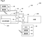
- FIG. 4 is an explanatory diagram for explaining the configuration of a junction section, a measurement section, and a control section. 4 is a flowchart showing an example of control of the water quality monitoring system.
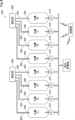
- FIG. 1 is an explanatory diagram showing a schematic configuration of a water quality monitoring system according to a comparative example.
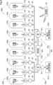
- FIG. 11 is an explanatory diagram showing a schematic configuration of a water quality monitoring system according to a second embodiment.
- FIG. 1 is an explanatory diagram showing a schematic configuration of a water quality monitoring system 100 according to an embodiment of the present disclosure.
- the water quality monitoring system 100 is a system for monitoring the water quality of aquatic organisms in a plurality of aquariums 200 in which aquatic organisms are cultured on land.
- the water quality monitoring system 100 constitutes a part of a land-based aquaculture system 300.
- the aquariums 200 included in the land-based aquaculture system 300 are shown by dashed lines.
- Target aquatic organisms in land-based aquaculture are not particularly limited, but include, for example, crustaceans such as shrimp and crabs, fish, shellfish, aquatic animals, marine mammals, and seaweed. Aquatic organisms may be immature individuals such as juvenile shrimp and juvenile fish, or may be mature individuals.
- the aquarium 200 is configured to store rearing water therein, and rears the aquatic organisms to be cultured.
- the rearing water is not particularly limited and is selected according to the aquatic organisms to be cultured.
- the rearing water is not particularly limited, but may be fresh water such as fresh water or well water, or salty water such as brackish water, seawater, or artificial seawater.
- the land-based aquaculture system 300 may be a closed circulation system in which all or almost all of the rearing water discharged from the aquarium 200 is circulated and returned to the aquarium 200, or may be a semi-closed circulation system in which a portion of the rearing water discharged from the aquarium 200 is circulated and returned to the aquarium 200. In FIG. 1, for convenience of illustration, the areas of eight aquariums 200 are shown out of the multiple aquariums 200 in the land-based aquaculture system 300.
- the water quality monitoring system 100 of this embodiment includes a pipe 20, a first valve 30, a junction 40, a second valve 50, a measurement unit 60, and a control unit 80.
- the pipes 20 are provided for each aquarium 200 and are connected to each of the aquariums 200.
- the first valve 30 is provided in the pipes 20.
- the first valve 30 is, for example, an electromagnetic valve, and the opening and closing state is controlled by the control unit 80.
- the control unit 80 controls the opening and closing state to control the control unit 80.
- the breeding water in the aquarium 200 is prevented from flowing out through the pipes 20.
- the first valve 30 is in the open state, the breeding water in the aquarium 200 is allowed to flow out through the pipes 20.
- a pump 210 for pumping the breeding water in the aquarium 200 is provided between the pipes 20 and the aquarium 200.
- the pipes 20 are drain pipes for draining the breeding water from the aquarium 200, and the pump 210 is a drain pump.
- the junction 40 joins the multiple pipes 20 downstream of the multiple pipes 20. A detailed description of the junction 40 will be given later.
- the second valve 50 is provided downstream of the junction 40.
- the second valve 50 is, for example, an electromagnetic valve, and the opening and closing state is controlled by the control unit 80.
- the control unit 80 controls the opening and closing state to the control unit 80.
- the second valve 50 is closed, the rearing water that flows in through the pipes 20 is stored in the junction 40.
- the second valve 50 is opened, the rearing water is discharged from the junction 40.
- the downstream side of the second valve 50 is connected to the wastewater storage unit 220.
- the wastewater storage unit 220 stores wastewater for a certain period of time.
- the wastewater storage unit 220 may be omitted, and the downstream side of the second valve 50 may be directly connected to the sewer system.
- FIG. 2 is an explanatory diagram for explaining the configuration of the junction 40, the measurement unit 60, and the control unit 80.
- FIG. 2 shows one of the multiple pipes 20 and one water tank 200 connected to it.
- the confluence 40 of this embodiment includes a manhole 44 through which the breeding water can overflow.
- the manhole 44 is formed with an opening at the vertical top, and a certain amount of breeding water can be stored inside. Since the manhole 44 through which the breeding water can overflow is included in the confluence 40, the water quality can be easily measured even in a mode in which the breeding water is collected and the water quality is measured. As a result, the system can be prevented from becoming complicated.
- the inside of the manhole 44 may be washed together by overflowing the breeding water of the aquarium 200 to be measured.
- the breeding water that overflows from the manhole 44 flows through the overflow line 46 to the drainage storage section 220.
- the second valve 50 provided downstream of the manhole 44 is closed, the breeding water is stored in the manhole 44, and when the second valve 50 is opened, the breeding water stored in the manhole 44 is drained into the drainage reservoir 220.
- the second valve 50 may be closed to fill the confluence 40 with breeding water from the aquarium 200 to be measured, and then the second valve 50 may be opened to drain the water, thereby washing the inside of the confluence 40 together.
- the measuring unit 60 measures the water quality of the rearing water stored in the junction 40.
- the measuring unit 60 measures the water quality of the rearing water by sampling and processing the rearing water stored in the junction 40.
- the measuring unit 60 measures the ammonium ion concentration.
- the measuring unit 60 in this embodiment includes a water sampling unit 62, a processing unit 64, and a communication unit 66.
- the water sampling unit 62 has a pump (not shown) and samples the rearing water stored in the junction 40 for measurement.
- the processing unit 64 has a sensor such as a diaphragm-type ion sensor (not shown) and adds a reagent such as a base to the sampled rearing water to measure the water quality.
- the processing unit 64 has a diaphragm-type electrode. Therefore, the measuring unit 60 has an ammonia sensor including a diaphragm-type electrode.
- the ammonia contained in the sampled rearing water is gasified and dissolved in the internal liquid after passing through a diaphragm (not shown), and its concentration is measured. Therefore, in the case of a diaphragm-type electrode, only ammonia contained in the rearing water is gasified and reaches the electrode, so that the influence of substances other than ammonia contained in the rearing water can be reduced, and the deterioration of the accuracy of the water quality measurement can be suppressed.
- the communication unit 66 is configured to be able to communicate with the communication unit 86 of the control unit 80 wirelessly or by wire.
- the communication unit 66 receives a water quality measurement instruction from the control unit 80, and outputs the water quality measurement result to the control unit 80.
- the control unit 80 is a computer equipped with a CPU (Central Processing Unit) 82, a memory unit 84, and a communication unit 86, and can perform various calculations, controls, and information processing.
- the CPU 82 controls various operations in the water quality monitoring system 100 by executing a program previously stored in the memory unit 84. More specifically, the control unit 80 (CPU 82) controls the first valve 30 and the second valve 50 provided for each aquarium 200, thereby storing and discharging the breeding water of a specific aquarium 200 in the confluence unit 40 (manhole 44).
- CPU Central Processing Unit
- the storage unit 84 stores identification information related to the aquarium 200, such as an aquarium number and type for identifying the aquarium 200.
- the type of the aquarium 200 is not particularly limited, but may be, for example, a juvenile shrimp aquarium in the early stage of aquaculture, an intermediate aquarium in the middle stage of aquaculture, a shipping aquarium in the final stage of aquaculture, etc.
- the storage unit 84 also stores the water quality measurement results acquired by the communication unit 86 in association with each aquarium 200.
- the communication unit 86 is configured to be able to communicate with an external device, such as the communication unit 66 of the measurement unit 60, by wireless or wired communication.
- FIG. 3 is a flow chart showing an example of the control of the water quality monitoring system 100.
- the control is started in a state in which the first valve 30 and the second valve 50 are closed.
- the control unit 80 determines whether or not it is a predetermined set time (step S110). If it is determined that it is not a predetermined set time (step S110: NO), step S110 is repeated. On the other hand, if it is determined that it is a predetermined set time (step S110: YES), the control unit 80 outputs a drain command to the PLC to drain the rearing water from the manhole 44 of the confluence unit 40 (step S115). When the drain command is output, the second valve 50 is opened and drainage is performed (step S120).
- the control unit 80 determines whether or not the drainage is complete (step S125). Whether or not the drainage is complete may be detected by, for example, a water level sensor or the like provided inside the manhole 44, or the manhole may be determined to be complete when a predetermined period of time has passed. If it is determined that the drainage is not complete (step S125: NO), the process returns to step S120 to continue the drainage operation. If it is determined that the drainage is complete (step S125: YES), the control unit 80 outputs a cleaning command to the PLC to clean the manhole 44 of the confluence 40 (step S130). When the cleaning command is output, cleaning is performed (step S135).
- the second valve 50 In cleaning, the second valve 50 is closed, and the first valve 30 provided in the piping 20 communicating with the aquarium 200 to be measured is opened, so that the manhole 44 of the confluence 40 is washed with the breeding water. After that, the second valve 50 is opened and the breeding water used for the co-washing is drained, completing the washing.
- the washing may be a co-washing performed by opening both the second valve 50 and the first valve 30, or may be performed by using fresh water or the like instead of the breeding water in the aquarium 200 to be measured.
- the control unit 80 determines whether or not the cleaning is complete (step S140). The cleaning may be completed when a predetermined period of time has elapsed. If the cleaning is not complete (step S140: NO), the process returns to step S135 and the cleaning operation continues. If the cleaning is complete (step S140: YES), the control unit 80 outputs a water injection command to the PLC to store the breeding water in the aquarium 200 to be measured in the manhole 44 of the junction 40 (step S145). When the water injection command is output, water is injected (step S150). In the water injection, the second valve 50 is closed and the first valve 30 provided in the piping 20 communicating with the aquarium 200 to be measured is opened.
- the control unit 80 determines whether or not the water injection is complete (step S155). Whether or not the water injection is complete may be detected, for example, by a water level sensor provided inside the manhole 44, or the water injection may be determined to be complete after a predetermined period of time has elapsed. If it is determined that the water injection is not complete (step S155: NO), the process returns to step S150 to continue the water injection operation. When the water injection is complete, the first valve 30, which was open until then, is closed.
- step S155 If it is determined that the water injection is complete (step S155: YES), the control unit 80 outputs a calibration, measurement, and cleaning instruction to the measurement unit 60 to measure the ammonium ion concentration (step S160).
- This calibration, measurement, and cleaning instruction causes the measurement unit 60 to perform calibration, measurement, and cleaning (step S165).
- step S165 the processing unit 64 calibrates the sensor, and then the water collected in the manhole 44 is collected by the water collection unit 62. The processing unit 64 then measures the water quality, and when the measurement is complete, the sensor is cleaned.
- the water quality measurement results are output to the control unit 80 via the communication units 66, 86, and the memory unit 84 stores the water quality measurement results together with the identification information of the aquarium 200.
- the control unit 80 determines whether the calibration, measurement, and cleaning are complete (step S170). Whether the calibration, measurement, and cleaning are complete may be determined, for example, by whether the communication unit 86 has received the water quality measurement results. If it is determined that the calibration, measurement, and cleaning are not complete (step S170: NO), the process returns to step S165 and continues.
- step S170 determines whether there is a water quality measurement instruction for the next aquarium 200 (step S175). Whether there is a water quality measurement instruction for the next aquarium 200 may be determined, for example, based on the aquarium number stored in the memory unit 84. For example, if the program is programmed to perform measurements in ascending order of aquarium numbers, it may be determined whether there is an aquarium 200 to be measured after the aquarium 200 after the water quality measurement is completed.
- step S175 If it is determined that there is a water quality measurement instruction for the next aquarium 200 (step S175: YES), the process proceeds to step S115, where the control unit 80 outputs a drainage instruction to the PLC to drain the breeding water from the manhole 44 of the confluence unit 40 (step S115). On the other hand, if it is determined that there is no water quality measurement instruction for the next aquarium 200 (step S175: NO), the process returns to step S110 and waits.
- the breeding water is collected at the junction 40 where the multiple pipes 20 join downstream of the multiple pipes 20, and the water quality is measured. Therefore, it is not necessary to install multiple measurement units 60, for example, for each aquarium 200. As a result, the number of measurement units 60 to be installed can be reduced, and the system can be prevented from becoming complicated.
- the pipe 20 also serves as a drain pipe for draining the breeding water from the aquarium 200, excessive intake of the breeding water in the aquarium 200 for measuring the water quality can be prevented.
- the water quality monitoring system 100 monitors the ammonium ion concentration, the degree of contamination of the breeding water can be managed for each aquarium 200.
- the water quality monitoring system 100 can monitor the water quality of the breeding water even in an embodiment in which the breeding water is seawater containing various ions.
- control unit 80 opens the second valve 50 (steps S115, S120), drains the rearing water stored in the junction 40 from the junction 40 (step S125: YES), and then closes the second valve 50. Thereafter, the control unit 80 opens the first valve 30 provided in the piping 20 communicating with the aquarium 200 for which water quality measurement has not been completed, which was identified in step S175 (steps S145, S150), to store the rearing water in the junction 40.
- the control unit 80 opens the first valve 30 provided in the piping 20 communicating with the aquarium 200 for which water quality measurement has not been completed, which was identified in step S175 (steps S145, S150), to store the rearing water in the junction 40.
- the control unit 80 drains the stored breeding water from the junction 40 (step S125: YES), and then cleans the junction 40 (steps S130, S135).
- This control flow can prevent a decrease in the accuracy of the water quality measurement and a decrease in the cleaning efficiency.
- the inside of the junction 40 is cleaned using the breeding water to be measured, so that the breeding water can be washed together with the breeding water to be measured, and the decrease in the accuracy of the water quality measurement can be further prevented.
- a drain command is output to the PLC (step S115), and the water is drained (step S120).
- the measurement can be performed even when the breeding water is accumulated in the junction 40 due to an unexpected error or the like. For example, even if the control unit 80 stops when the manhole 44 is filled with breeding water, the manhole 44 is first drained, so the state of the manhole 44 can be reset.
- FIG. 4 is an explanatory diagram showing a schematic configuration of a water quality monitoring system 500 of the comparative example.
- the confluence section is omitted.
- a water sampling section 562 of the measurement section 560 is provided for each aquarium 200, and the entire system has multiple measurement sections 560.
- the system since it has multiple measurement sections 560, the system becomes complicated. As a result, the initial cost and running cost of the system increase.
- breeding water is sampled separately from the wastewater.
- the measurement section 560 has four water sampling sections 562, and one measurement section 560 is provided for each of the four aquariums 200, so the length of the water sampling section 562 becomes redundant. As a result, an excessive amount of rearing water in the aquarium 200 is taken, exceeding the allowable water intake amount of the aquarium 200, resulting in a situation in which water quality measurement is not possible.
- the breeding water of the aquarium 200 to be measured is stored in the confluence 40 and the water quality is measured, so the number of measuring units 60 to be installed can be reduced, simplifying the system.
- Second embodiment: 5 is an explanatory diagram showing a schematic configuration of a water quality monitoring system 100a of the second embodiment.
- the water quality monitoring system 100a of the second embodiment differs from the water quality monitoring system 100 of the first embodiment in the configurations of the confluence section 40a and the measurement section 60a. Since the other configurations are the same as those of the water quality monitoring system 100 of the first embodiment, the same components are denoted by the same reference numerals and detailed descriptions thereof are omitted.
- the land-based aquaculture system 300a equipped with the water quality monitoring system 100a of the second embodiment is equipped with multiple tanks 200a of different types. More specifically, it is equipped with multiple baby shrimp tanks 250a, multiple intermediate tanks 260a, and multiple shipping tanks 270a.
- the baby shrimp tank 250a houses more immature individuals than those housed in the intermediate tanks 260a and the shipping tank 270a.
- the land-based aquaculture system 300a in the second embodiment is provided with a first wastewater storage section 221a that stores wastewater from the juvenile shrimp tank 250a, and a second wastewater storage section 222a that stores wastewater from the intermediate tank 260a and the shipping tank 270a.
- FIG. 5 shows the areas of nine tanks 200a out of the multiple tanks 200a in the land-based aquaculture system 300a.
- the confluence 40a in the second embodiment includes a first confluence 41a and a second confluence 42a.
- the first confluence 41a is connected to a pipe 20 that communicates with a juvenile shrimp tank 250a in which immature individuals are raised among the multiple tanks 200a. Therefore, the first confluence 41a stores the rearing water of the juvenile shrimp tank 250a.
- a second valve 51a is provided downstream of the first confluence 41a and is connected to a first drainage storage section 221a.
- the second confluence 42a is connected to a pipe 20 that communicates with an intermediate tank 260a and a shipping tank 270a in which more mature individuals are raised among the multiple tanks 200a. Therefore, the second confluence 42a stores the rearing water of the intermediate tank 260a and the shipping tank 270a.
- a second valve 52a is provided downstream of the second junction 42a and is connected to the second drainage reservoir 222a.
- the measuring unit 60a has two water sampling units 62a. One of the two water sampling units 62a samples the rearing water stored in the first junction 41a. The other of the two water sampling units 62a samples the rearing water stored in the second junction 42a. With this configuration, the measuring unit 60a measures the water quality of the rearing water stored in the first junction 41a and the water quality of the rearing water stored in the second junction 42a.
- the water quality monitoring system 100a of the second embodiment described above includes a first confluence section 41a for storing the rearing water of the tank 200a (baby shrimp tank 250a) in which immature individuals are reared, and a second confluence section 42a for storing the rearing water of the tank 200a (intermediate tank 260a, shipping tank 270a) in which more mature individuals are reared, so that the rearing water of the tank 200a in which immature individuals are reared and the rearing water of the tank 200a in which more mature individuals are reared are prevented from mixing and being discharged.
- the water quality monitoring system 100a may be provided with multiple confluence sections 40a depending on the purpose, etc.
- the configuration of the water quality monitoring system 100, 100a in the above embodiment is merely an example, and can be modified in various ways.
- the piping 20 in the above embodiment also serves as a drain pipe for draining rearing water from the aquarium 200, 200a, but is not limited to a drain pipe and may be any piping such as a water intake pipe provided for water quality measurement.
- the measurement unit 60, 60a in the above embodiment measures the ammonium ion concentration, but the present disclosure is not limited thereto.
- mineral concentrations such as calcium, magnesium, and sodium may be measured, and dissolved oxygen concentration, carbon dioxide concentration, nitrate concentration, oxidation-reduction potential, conductivity, pH, temperature, etc.
- the measurement unit 60, 60a may have a sensor according to the measurement item of water quality, and the water sampling unit 62, 62a may be omitted depending on the measurement method of water quality.
- the confluence unit 40, 40a has a manhole 44, but the manhole 44 may be omitted. In an embodiment in which the manhole 44 is omitted, any configuration capable of collecting the rearing water of the multiple aquariums 200, 200a in one place may be used, and for example, the confluence 40, 40a may be composed only of piping.
- the water quality monitoring system 100, 100a may include the aquariums 200, 200a.
- water quality monitoring is not limited to a preset time, but may be performed when any preset condition is met, such as every preset period of time or after the water in the aquariums 200, 200a has been replaced.
- water quality monitoring is not limited to sequentially measuring the water quality of the water in the aquariums 200, 200a where water quality measurement has not been completed, but may be performed according to a preset program.
- step S150 the breeding water may be allowed to overflow in the manhole 44 for a certain period of time to be washed together, and then stored in the confluence 40 (manhole 44). That is, the control unit 80 may close the first valve 30 after allowing the breeding water to overflow from the manhole 44 of the confluence 40, 40a for a certain period of time.
- This certain period may be, for example, a predetermined time, or a period during which a predetermined amount of breeding water overflows.
- the present invention is not limited to the above-described embodiments, and can be realized in various configurations without departing from the spirit of the present invention.
- the technical features in the embodiments and examples corresponding to the technical features in each aspect described in the Summary of the Invention column can be replaced or combined as appropriate to solve some or all of the above-described problems or to achieve some or all of the above-described effects.
- a technical feature is not described in this specification as essential, it can be deleted as appropriate.
Landscapes
- Life Sciences & Earth Sciences (AREA)
- Chemical & Material Sciences (AREA)
- Health & Medical Sciences (AREA)
- Physics & Mathematics (AREA)
- Analytical Chemistry (AREA)
- Biochemistry (AREA)
- General Health & Medical Sciences (AREA)
- General Physics & Mathematics (AREA)
- Immunology (AREA)
- Pathology (AREA)
- Engineering & Computer Science (AREA)
- Environmental Sciences (AREA)
- Hydrology & Water Resources (AREA)
- Animal Husbandry (AREA)
- Biodiversity & Conservation Biology (AREA)
- Marine Sciences & Fisheries (AREA)
- Environmental & Geological Engineering (AREA)
- Water Supply & Treatment (AREA)
- Organic Chemistry (AREA)
- Food Science & Technology (AREA)
- Medicinal Chemistry (AREA)
- Farming Of Fish And Shellfish (AREA)
Abstract
L'invention concerne une technologie qui peut supprimer une complexité dans un système de surveillance de la qualité de l'eau en agriculture terrestre. Le système de surveillance de la qualité de l'eau en agriculture terrestre est caractérisé par le fait qu'il comprend : des conduits communiquant respectivement avec une pluralité de réservoirs d'eau ; des premières vannes ménagées sur les conduits ; une unité de fusion qui fusionne une pluralité de conduits à un point en aval de la pluralité de conduits ; une seconde vanne ménagée en aval de l'unité de fusion ; une unité de mesure pour la mesure de la qualité de l'eau ; et une unité de commande, l'unité de commande commandant les premières vannes et la seconde vanne de telle sorte que de l'eau d'élevage dans le réservoir d'eau est stockée dans l'unité de fusion, et l'unité de mesure mesure la qualité de l'eau de l'eau d'élevage stockée dans l'unité de fusion.
Applications Claiming Priority (2)
| Application Number | Priority Date | Filing Date | Title |
|---|---|---|---|
| JP2023148792 | 2023-09-13 | ||
| JP2023-148792 | 2023-09-13 |
Publications (1)
| Publication Number | Publication Date |
|---|---|
| WO2025057504A1 true WO2025057504A1 (fr) | 2025-03-20 |
Family
ID=95021058
Family Applications (1)
| Application Number | Title | Priority Date | Filing Date |
|---|---|---|---|
| PCT/JP2024/020124 Pending WO2025057504A1 (fr) | 2023-09-13 | 2024-05-31 | Système de surveillance de la qualité de l'eau |
Country Status (1)
| Country | Link |
|---|---|
| WO (1) | WO2025057504A1 (fr) |
Citations (5)
| Publication number | Priority date | Publication date | Assignee | Title |
|---|---|---|---|---|
| JPH0489566A (ja) * | 1990-07-31 | 1992-03-23 | Furuno Electric Co Ltd | 水質環境監視装置 |
| JP2003052275A (ja) * | 2001-08-13 | 2003-02-25 | Eruson Kk | 魚介類の養殖方法および閉鎖循環式養殖システム |
| WO2009153979A1 (fr) * | 2008-06-16 | 2009-12-23 | シープラス株式会社 | Appareil piscicole en circuit fermé et procédé de pisciculture |
| JP2021013908A (ja) * | 2019-07-16 | 2021-02-12 | 日本特殊陶業株式会社 | 水質計測システム |
| KR20210050110A (ko) * | 2019-10-28 | 2021-05-07 | 주식회사 글로비트 | 수질 측정 방법 및 시스템 |
-
2024
- 2024-05-31 WO PCT/JP2024/020124 patent/WO2025057504A1/fr active Pending
Patent Citations (5)
| Publication number | Priority date | Publication date | Assignee | Title |
|---|---|---|---|---|
| JPH0489566A (ja) * | 1990-07-31 | 1992-03-23 | Furuno Electric Co Ltd | 水質環境監視装置 |
| JP2003052275A (ja) * | 2001-08-13 | 2003-02-25 | Eruson Kk | 魚介類の養殖方法および閉鎖循環式養殖システム |
| WO2009153979A1 (fr) * | 2008-06-16 | 2009-12-23 | シープラス株式会社 | Appareil piscicole en circuit fermé et procédé de pisciculture |
| JP2021013908A (ja) * | 2019-07-16 | 2021-02-12 | 日本特殊陶業株式会社 | 水質計測システム |
| KR20210050110A (ko) * | 2019-10-28 | 2021-05-07 | 주식회사 글로비트 | 수질 측정 방법 및 시스템 |
Similar Documents
| Publication | Publication Date | Title |
|---|---|---|
| US4300909A (en) | Process control | |
| KR100654105B1 (ko) | 밸러스트 워터의 유기물 제어 방법 및 장치 | |
| KR102386303B1 (ko) | 육상 양식장용 순환여과 양식 시스템 | |
| US5961831A (en) | Automated closed recirculating aquaculture filtration system and method | |
| US20040211731A1 (en) | Method for monitoring and controlling chlorine levels in an aqueous medium | |
| KR102150651B1 (ko) | 실시간 어장환경정보 획득시스템 | |
| US20230200318A1 (en) | Aqueous grow chamber recirculating nutrient control system and sensor calibration | |
| CN105067545A (zh) | 一种消毒液浓度检测方法及使用该方法的浓度监测装置 | |
| Shaidani et al. | Animal maintenance systems: Xenopus tropicalis | |
| JP5667106B2 (ja) | バラスト水の水質監視方法及び水質監視装置 | |
| KR102756723B1 (ko) | 센서 세척 장치 및 이를 이용한 양식 수조 관리 시스템 | |
| JP2024006494A (ja) | 塩素濃度の制御方法、水処理装置の洗浄システム、プログラム、及び水循環型水処理装置 | |
| JP2019047783A (ja) | 海水濾過装置と補水用海水の濾過方法 | |
| US20230054730A1 (en) | Water quality measurement device and storage method for water quality measurement device | |
| Garcia et al. | An automated power of hydrogen controlled filtration system for enhanced aquarium fish farming. | |
| Shaidani et al. | Animal maintenance systems: Xenopus laevis | |
| CN205367769U (zh) | 一种智能水循环系统 | |
| JP3212449B2 (ja) | 海苔網薬剤処理装置 | |
| JP2002336614A (ja) | 水族館等の水処理設備における海水濾過器の淡水・海水逆洗濾過システム | |
| JPH11289912A (ja) | 車えび養殖池の消毒再生方法 | |
| JPH0712802A (ja) | 水質モニタ装置および水質モニタ方法 | |
| JPH0489566A (ja) | 水質環境監視装置 | |
| KR101024036B1 (ko) | 질산화 박테리아를 이용한 생태 독성 감지 시스템 | |
| WO2025141906A1 (fr) | Système de gestion de la qualité de l'eau dans l'aquaculture terrestre de crustacé, et procédé de production de crustacé | |
| CN206033759U (zh) | 船舶压载水中10‑50um生物快速检测装置 |
Legal Events
| Date | Code | Title | Description |
|---|---|---|---|
| 121 | Ep: the epo has been informed by wipo that ep was designated in this application |
Ref document number: 24865012 Country of ref document: EP Kind code of ref document: A1 |